3-1, Shinchi, Fuchu-cho, Aki-gun Hiroshima , Japan TEL : 81(82) FAX : 81(82) Technical
|
|
|
- Edwin Cummings
- 6 years ago
- Views:
Transcription
1 Service Information 3-1, Shinchi, Fuchu-cho, Aki-gun Hiroshima , Japan TEL : 81(82) FAX : 81(82) Category Coverage S Distributor only Please inform your dealers Technical Please convey this information to your Director General Manager Warranty Dept. Parts Dept. Training Dept. Field Rep. Applicable Models Ref. No. E034/07B Date Issued Date Revised Applicable Countries or Specifications Page 1 of July 30, 2007 July 28, 2010 All model vehicles Europe Subject: Rust / Perforation Repair Procedure for Rear Fender Arch REVISED Revision Notes: Table with corrosion Level Criteria on page 3 has been changed to fit with new policy. P/N information has been modified. Guidelines for corrosion level assessment of corresponding components have been implemented as APPENDIX A displayed on pages The updated sections are highlighted. Note: This Service information supersedes E003/06 This service information provides you with the repair criteria and the repair procedure against the rust / perforation on the rear fender arch, in order to promote the proper repair. When you encounter a customer complaint on this concern, first check the level of rust / perforation, and then repair the rear fender arch according to the criteria and procedure mentioned in the following pages Shinji Kanai Manager, Technical Information Gr. Technical Service Dept. Mazda Motor Co.

2 Page 2 of 49 How to evaluate the Corrosion Level on a vehicle brought into your workshop? The following tables will show you sample pictures of different Corrosion Levels that can appear at the rear fender panel. Use these tables as a guideline and to judge the present Corrosion Level on vehicles brought into your dealership. If you will get into trouble with the judgment of corrosion Level with regards to make a clear statement if the corrosion visible on a car is Corrosion Level 1 or Corrosion Level 2, please contact your local Prior Approval Operator. To simplify the process of the judgment for your Prior Approval Operator, please provide meaningful pictures, which are representing the current situation on the component you need to judge. Deliver all known facts about warranty status and the history of previous measures that has been done to the vehicle and especially to the component you need to judge. Rear Fender Arch Corrosion Repair Why This Repair is Effective: The hardener has nature that absorbs the water then hardens, which shut off water supply and stop rust from spreading even if water has already entered. Vital Points of Repair: Apply the hardener from the top of the fender arch toward the lower part so that the hardener penetrates into all over the mating panels of arch flange. Apply hardener and allow it to penetrate into the mating panels.
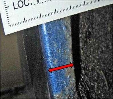
 1 Adhesive Sealer 2 Paint Sealer AND Level - 1 Visible blisters less than or equal to 10mm from the inner edge of the fender arch.")
 Less than or equal to 10mm 1 Adhesive Sealer 2 Paint Sealer OR Level-2 Visible blisters and corrosion in an area more than 10mm from the inner edge of the fender arch.")
3 Page 3 of 49 Corrosion Level Level - 0 No damage on the paint sealer.(*) AND Evaluation Criteria for Rear Fender Arch Flange No visible blisters/peeling/corrosion on the rear fender arch. Action Required - No damage on the Paint Sealer.(*) 1 Adhesive Sealer 2 Paint Sealer AND Level - 1 Visible blisters less than or equal to 10mm from the inner edge of the fender arch. (Even if corrosion appears in blisters.) Blister Repair Paint Sealer damages.(*) Less than or equal to 10mm 1 Adhesive Sealer 2 Paint Sealer OR Level-2 Visible blisters and corrosion in an area more than 10mm from the inner edge of the fender arch. Repair Blister More than 10mm 1 Adhesive Sealer 2 Paint Sealer Level-3 Perforation in outer panel. OR Perforation in inner panel. Replace Perforation (*): Mazda3, Mazda6, RX-8 only: Due to No sealer application(2), 323, MPV and Premacy are not affected this criteria NOTE: Find the detailed guidelines for corrosion level assessment explained in Appendix A at the end of this Service Information on pages
4 Material to be used No. Material Short Text Supplier Brand Brand Name Mazda Part No. E034/07B Page 4 of 49 Remark I II III IV V VI VII Corrosion Protection Primer Weld Primer Primer Surfacer Paint Sealer Anti-Corrosion W ax Stone Chip Protection Material Chipping primer DuPont PPG AKZO NOBEL BASF Foerch Standox Etching Adhesion Primer DuPont Refinish Etching Primer 635R Spies-Hecker Priomat Wash Primer 4075 NEXA Autocolor P PPG D831 Sikkens Lesonal R-M Glasurit Washprimer EM CF 2K Etch Primer Eurofill VOC L233 L208 To avoid any incompatibility, please apply a Primer Surfacer that is recommended to use with the paint material and already applied Corrosion Protection Primer used in your workshop (for details contact your local paint manufacture). Henkel Teroson Terostat 9120 WUERTH sabesto BOND+SEAL ALL-IN-ONE Clinched Flange Sealer DD10-FS Anti Corrosion Cavity Wax 0,5l Aerosol Anti Corrosion Cavity Wax 1l Can Stone Chipping Coating (grey)1l Can Stone Chipping Coating (black)1l Can Stone Chipping Coating (grey) 1l Can Stone Chipping Coating (black)1l Can DN05-BL-MLS-9A DN10-BL-MLB-9A DN10-GR-442-9A DN10-BL-442-9A DN10-GR-440-9A DN10-BL-445-9A unit per vehicles VIII Cleaning Agent To avoid any incompatibility, please use a cleaning agent that is recommended by the supplier of your paint materials used in your workshop. (for details contact your local supplier manufacture). IX Tin-Solder Bar To avoid any incompatibility, please use Tin-Solder Bars that are recommended by the supplier of your paint materials used in your workshop. (for details contact your local supplier manufacture). X Spatula Kit Contains different type of spatulas to smoothen the silicone sealant W3-101* Spatual Kit's are not available any longer. Please make use of those Spatula locally availble and applicable to be used for this operation. One spatula for many vehicles XI Hardener Hardener 1L Can R001-SL XII XIV Fender Sealant (Silicone sealant) (black) Vinyl Tape (black) Vinyl Tape (yellow) Black Half Transparent Thickness 0.15mm Length 33m Thickness 0.15mm Length 33m 310ml Cartridge 100ml Cartridge 11RT-V7-091 K100-W 0-590A HC R001-TE-100 R002-TE cartrige per 3 vehicles one color: 1 unit per 10 vehicles Other color: 1 unit per 20 vehicles
 Apply chipping primer (VII) to the joint area of rear fender and bumper.")
5 Level 1 Repair procedure for rear wheel fender arch flange Outline of Repair Procedure Page 5 of 49 Application of Chipping Primer (VII) Apply chipping primer (VII) all along the fender. (Application width: 2 mm) Apply chipping primer (VII) to the joint area of rear fender and bumper. MSP1_001 1 Grommet 2 Chipping primer (VII) 3 Application area

6 Application of Silicone Sealant to All Along the Rear Fender Arch Page 6 of 49 Apply silicone sealant to the inner area of flange edges. Apply silicone sealant to horizontal flange surface of rear wheel fender. MSP1_002 1 Application area 3 Flange surface 2 Inner area of flange edge

7 Repair Procedure E034/07B Page 7 of Jack up the vehicle and remove the tires and the mud guards. 2. Remove the screws from the front-side rear bumper installation location. 3. Pull the rear bumper toward you, and insert a piece of cloth between the rear bumper and the rear fender. NOTE: To avoid any contamination of the brake system with chipping primer (VII) or silicone sealant, cover the area 3 shown in the picture below with a suitable protection sheet or foil. NOTE: It is not necessary to fully remove the Mud Guard to proceed the prevention work. If the Mud Guard has already been removed for any other reason be careful not to damage the applied silicone sealant during reassembly MSP1_003 1 Cloth 3 Cover 2 Remove the screws 4 Rear bumper
8 Page 8 of Clean and degrease the fender arch flange at locations A and B by using a waste cloth. MSP1_004 NOTE: Use suitable brush to clean the area B carefully from dust and sand. Take care not to damage the original paint sealer. NOTE: In order to ensure a good adhesion of the silicone sealant, clean and degrease the surface A and B where the silicone sealant will be applied.

 does not have paint sealer, therefore it is not necessary to perform this step.")
, lightly sandpaper the coating surface so that the coating can affix well.")
9 Page 9 of Make sure there is no break or damage on the sealer. If you will find any damage on the paint sealer, corrosion possibly has already appeared inside of the panel joint and corrosion prevention cannot be effective. In such cases remove the paint sealer and perform repair regarding to the level 2 repair procedure.. NOTE: Some models(323, MPV and Premacy,etc) does not have paint sealer, therefore it is not necessary to perform this step. MSP1_005 1 Mirror Correct MSP1_006 Incorrect MSP1_007 1 Break in paint sealer 6. As a preparation for the application of chipping primer (VII), lightly sandpaper the coating surface so that the coating can affix well. NOTE: Using a sandpaper, lightly stroke the paint surface a couple of times. 7. Apply masking tape as specified in the following procedure.
 will be covered completely by the later applied black silicone sealant (XII).")
10 Areas To Be Covered By Masking Tape For Chipping Primer (VII) Application E034/07B Page 10 of 49 Black silicone sealant (XII) need to be used, install the masking tape to the joint of the fender and bumper only. NOTE: The installed chipping primer (VII) will be covered completely by the later applied black silicone sealant (XII). Therefore it is not necessary to apply masking tape to the flange surface. 1 Masking tape MSP1_ Apply the chipping primer (VII) according to the following application procedure.
 becomes approx. 0.5 mm. Make sure that the body colour cannot be seen anymore in this area. NOTE: Allow the chipping primer (VII) to dry for a few minutes before you will apply the next layer.")
 PURPOSE: The purpose of the applied chipping primer (VII) and the afterwards installed vinyl tape is to act as a guide way to ensure a specified material thickness of approx. 0,5mm.")
11 Chipping Primer(VII) Application Procedure E034/07B Page 11 of 49 Black silicone sealant (XII) is used, apply 3 layers of chipping primer (VII) with a brush until the thickness of the chipping primer (VII) becomes approx. 0.5 mm. Make sure that the body colour cannot be seen anymore in this area. NOTE: Allow the chipping primer (VII) to dry for a few minutes before you will apply the next layer. When application is finished, allow the chipping primer (VII) to dry for approx. 30 minutes. (Lightly touch the surface to check if it is dry.) PURPOSE: The purpose of the applied chipping primer (VII) and the afterwards installed vinyl tape is to act as a guide way to ensure a specified material thickness of approx. 0,5mm. Furthermore they will be used to guide the spatula during spreading the silicone sealant to the area between chipping primer (VII) and vinyl tape. So the finish of the silicone sealant surface is highly depending on the quality of the chipping primer (VII) and vinyl tape application. 9. Apply vinyl tape as shown in the following illustration. Apply approx. 3 plies of the vinyl tape until the thickness is approx. 0.5 mm. MSP1_016 1 Vinyl tape 2 Corner start NOTE: Using different colors of vinyl tape for each ply will simplify the application because you can align the edge of the tape exactly along the edge of the previously applied layer of tape. NOTE: Avoid breaks in the tape during application. Otherwise the edges caused by the brakes in the tape will be transferred to the surface of the silicone material


12 Page 12 of Prepare nozzle No. 1 for the application of the silicone sealant to the inner edge of the rear fender arch flange as shown on the following picture. 1 Close the whole by using a screw MSP1_080 WARNING: For the necessary protection measures please refer to the corresponding safety data sheet available at or contact your National Sales Company or Independent Distributor. CAUTION: Do not perform silicone sealant application in a paint workshop in order to ensure the quality of paint finish. 11. Position the nozzle to the inner edge of the flange and apply the silicone sealant all along the rear fender arch flange. MSP1_081


13 Page 13 of 49 NOTE: Do not guide the nozzle by pressing the V-shape onto the edge because the chipping primer will get damaged. Guide the nozzle gently along the edge of the flange by ensuring the edge runs in between the V-shape. 12. Close the V-shape of nozzle No. 1 by wrapping around vinyl tape. This will prevent the silicone sealer from drying. MSP1_083 1 Vinyl Tape 13. Arrange the applied silicone sealant onto the back of the flange by using your finger. Please ensure to wear protection gloves when spreading the material in this way. MSP1_015 1 Protection Glove
. So re-install nozzle No.")

14 Page 14 of 49 NOTE: Spread the material in a gentle way, otherwise you will wipe off the material from inner edge of the flange. Check the result by using a miror. NOTE: Please keep in mind that the delivered 310ml cartridges will last for about 3 vehicles (2 rear fenders per vehicle). So re-install nozzle No.1 onto the cartridges after complete application is finished and close the V-shape of the nozzle by wraping arround some vinyl tabe. This will avoid the remaining sealer from drying. You can leave nozzle No.2 unprotected because the dried sealer can be removed easily. MSP1_017 1 Vinyl tape 3 Chipping primer 2 Make sure the edge of the tape is aligned with the edge of the chipping primer. 14. Prepare nozzle No. 2 for the application of the silicone sealant as shown on the following pictures. MSP1_082


15 Page 15 of Apply the silicone sealant to all along the flange surface. MSP1_018 1 Silicone sealant 16. Spread the silicone sealant all along the flange surface by using a spatula. MSP1_019 1 Silicone sealant 2 Spatula


16 Page 16 of 49 Correct MSP1_020 Incorrect MSP1_021 NOTE: If the spatula is set vertically to the flange surface, streams will appear on the silicone sealant. Set the spatula at an angle of 45 degrees against the flange. Do NOT allow air bubbles to be trapped into the silicone sealant. NOTE: Because the spatulas can be used several times, ensure there are no grooves or scratches on the surface of the spatulas before smoothen out the Silicone material. NOTE: Smooth out the surface of the silicone sealant using a spatula IMMEDIATELY after the silicone selant is applied. Otherwise, the silicone sealant gets hardened and uneven coating (marks) will easily appaer. NOTE: Do finish of the silicone sealant with the spatula from the front side to the rear side of the tyre arch at a brush. (Don t stop in the middle, or a poor appearance may occur in the joint area.) 17. Remove the vinyl tape immediately after the spreading process of silicone sealant has finished.

17 How To Peel Off the Vinyl Tape E034/07B Page 17 of 49 Remove the vinyl tape immediately after the silicone sealant has been spread and smoothed. When removing, the vinyl tape should be pulled toward the applied silicone sealant. If it is pulled to the wrong side, the applied silicone sealant will be cling to the vinyl tape causing an unpleasant appearance at the visible corners of the silicone sealant. 18. Allow the silicone sealant to dry for approx. 30 minutes until skin formation has finished. MSP1_022 NOTE: If the vehicle will be kept at the dealership, allow the silicone sealant to dry for the whole day. (Because it will get completely dry.) 19. Reassemble the rear bumper with the screws. 20. Reassemble the mud guards and the tires. NOTE: Do not allow any damage to the applied silicone sealant. 21. Lower the vehicle. Before returning the vehicle to the customer, be sure to pay attention to the following: Do not drive in rain until the silicone sealant gets completely dry. If the customer is likely to drive on a rough road (where the vehicle is easily subject to stone chipping), return the vehicle after the silicone sealant is completely dry.


18 Page 18 of 49 Level 2 Repair procedure for rear wheel fender arch flange 22. Detach the tires, the mud guards and any other vehicle parts necessary to obtain clear access. Protect the other surrounding vehicle parts with suitable material such as masking paper or other protective materials which are usually employed in the body workshop. 23. Use an air tool with a wire brush or equivalent, to completely remove the paint sealer from the rear and inner area of the wheel arch. BL-1010_ Use a wire brush or equivalent tool, to clean the inside and outside of the rear fender arch from old paint and underbody protection material. Clean the entire surface from existing corrosion patterns. BL-1010_02025 NOTE: Remove the sealer from all the visible corroded areas. If necessary, also remove it from the rear side of the fender arch.


19 Page 19 of All areas which cannot be treated by the method described above must be sand blasted. This ensures that all traces of corrosion plus dirt and sealer or paint residues are removed completely. BL-1010_02026 NOTE: If you will discover black or grey spots on the bare sheet metal as shown on the picture below, remove them by grinding them off to the blank metal. Such spots are caused by a damaged phosphate coating and need to be removed accurate. Otherwise the corrosion protection measures are not sufficient. BL-1010_02104

 using abrasive paper.")
20 26. Remove any loose rust from the spaces between the panels using an oscillating tool. E034/07B Page 20 of 49 BL-1010_ Carefully deburr the cut edges of all the panels (rear quarter panel, wheelhouse on the inside) using abrasive paper. This will improve the adhesion when paint sealer (IV) and varnish are applied to the edges of the panels later. BL-1010_02028

 by using a suitable cleaning agent (VIII). 30.")
21 Page 21 of Apply pure hardener (XII) to the joined surface all along the rear fender panel. Allow the material to penetrate in between the panels. BL-1010_02029 NOTE: Allow the hardener (XI) to penetrate for at least 30 minutes. 29. Wipe off surplus hardener (XI) by using a suitable cleaning agent (VIII). 30. Clean and degrease those surfaces where the corrosion has been removed. 31. Apply corrosion protection primer (I) over the entire repair area and make sure that all the bare surfaces are treated. BL-1010_02030
 abrasive paper and then clean it to remove any surface irregularities. 33.")
22 Page 22 of Apply primer surfacer (III) over the repair area and let it dry. Lightly sand the surface with (500 grit) abrasive paper and then clean it to remove any surface irregularities. 33. Apply paint sealer (IV) over the entire inner edge of the fender arch (from the rocker panel to the mounting point of the bumper). BL-1010_02031 BL-1010_02067
 2 Wheelhouse 34.")
23 Page 23 of 49 NOTE: Make sure that paint sealer (IV) is applied exactly in the area of the junction between the outer panel and the inner panel as shown in the diagram on the left below. Correct BL-1010_02033 Incorrect BL-1010_ Rear quarter panel 3 Paint Sealer (IV) 2 Wheelhouse 34. In the same way, also apply additional paint sealer (IV) to the area where the rear bumper meets the outer panel and the inner panel (see illustration below) Area where the rear bumper meets the outer panel and the inner panel BL-1010_02102
24 Page 24 of Apply stone chip protection material (VI or VII) in the affected area as shown on the illustration below No Apply the stone chip protection material (VI or VII) to the flange arch that it covers the edge of the panels as illustrated below No.4. BL-1010_ Anti-corrosion wax (V) 4 Stone chip protection material (VI or VII) 2 Stone chip protection material (VI or VII) 5 Factory applied adhesive sealer 3 Paint sealer (IV) 6 Hardener 37. Apply the finishing paint.
25 38. Apply anti-corrosion wax (V) from the inside: E034/07B Page 25 of 49 Remove the trim. Treat the area between the inner wheelhouse and the rear quarter panel with anti-corrosion wax (V) from the inside. Guide a hose into the area between inner and outer panel. BL-1010_ Apply Anti-corrosion wax (V) 2 Rocker panel Guide a hose into the opening in the rocker panel for cavity sealing and apply anti-corrosion wax (V) to the junction between the inner and outer panels. Allow the anti-corrosion wax (V) to penetrate to the areas between inner and outer panel from the inside over the entire length of the wheel arch. 39. Refit the trims, mud guard, rear tire and the rear bumper. 40. Remove all visible material residues from the vehicle and handle the car back to the customer. BL-1010_02067

26 Page 26 of 49 Repair procedure for replacement of rear fender panel Repair procedure 41. Detach the rear bumper, rear tire and mud guard on the side to be repaired. 42. Detach all the attached parts and trim, e.g. rear scuff plate, wheelhouse trim, inner side luggage compartment trim, upper side luggage compartment trim, lower side luggage compartment trim, etc. on the side to be repaired. BL-1010_02075

27 Page 27 of For preparation of the repair panel first roughly mark out the area to be repaired and then cut out a matching section from the service part or a rear quarter panel using a suitable tool such as a pneumatic saw or similar. Also cut a suitable weld backing strip to size. NOTE: Service parts for the rear quarter panel are available for the 626 Wagon / Sedan / Hatchback, 323 Hatchback, NOTE: Part No. for Mazda3 Sedan / Hatchback and Mazda6 Wagon / Sedan / Hatchback repair panel can be found on SI E058/07 Picture shows service parts for Mazda 626 BL-1010_ Service part 4 After cutting to size 2 Section cut to size 5 Before cutting to size 3 Weld backing strip cut to size

28 44. Fit outer repair panel onto remaining outer panel and secure in place. E034/07B Page 28 of 49 BL-1010_ Mark cut line on remaining outer panel along repair panel. BL-1010_02077 NOTE: The cut line varies from model to model. Therefore please make the cut as specified for the particular model. As an example, the cut line on the rear quarter panel of the Mazda 626 (GF/GW) is shown in the following diagram.

29 Page 29 of 49 BL-1010_ Marked location on inner panel 3 Cut line 2 Factory applied adhesive sealer 4 Rear door NOTE: Starting from the marked location on the inner panel, cut mm off the rear quarter panel (outer panel).

30 Page 30 of Cut out the rear quarter panel along this line using a suitable tool such as a pneumatic saw, etc. Leave sufficient material for easy overlapping if not using a trimmed weld backing strip. 47. If necessary, mark the centre points of the spot welds (10 spot welds) on the flange with a centre punch and drill out using a spot weld drill (diameter: approx. 8.0 mm). NOTE: If necessary, remove the stone chip protection material applied in the area of the rocker panel using a wire brush to locate the spot welds more easily. 1 Before removing spot welds 3 Remove stone chip protection material 2 After removing spot welds 48. Remove the burrs from the drilled spot welds. 49. Correct any deformation of the fender arch when necessary. BL-1010_ Heat the area in which the factory applied adhesive sealer is applied using a hot air blower (650 W) and detach the panel.
31 Page 31 of Remove all rust and sealer between the inner and outer panels using a wire brush or a knife so that the Hardener will spread better later. 52. Then clean the area. Work along the dotted line with a wire brush. BL-1010_02087 NOTE: If corrosion and/or sealer cannot be removed with a wire brush or knife, use sand blasting equipment. NOTE: If you will discover black or grey spots on the bare sheet metal, remove them by grinding them off to the blank metal. Such spots are caused by a damaged phosphate coating and need to be removed accurate. Otherwise the corrosion protection measures are not sufficient.


32 Page 32 of If you discover perforation or severe corrosion on the inner panel which cannot be removed completely, a sectional replacement of the inner panel might be necessary. Otherwise continue with step Cut inner repair panel out out inner panel service part to a size that covers all the affected areas. 55. Fit the inner repair panel on top of the existing inner panel and secure it in place. BL-1010_02200 BL-1010_02172


33 Page 33 of Mark line on existing inner panel along edges of inner repair panel. 57. Drill out the spot welds from the inner panel which are necessary to remove the section to be replaced. BL-1010_02174 NOTE: Wherever possible it is recommended to use spot welding technique to fix the repair panels instead of MIG/MAG welding. 58. Cut out the section, but leave 10mm for overlapping in the spot welding areas. BL-1010_02175


34 59. Sand all welding areas down to bare metal. E034/07B Page 34 of 49 NOTE: Insure to remove the phosphate coating from all welding areas. 60. Prepare an joggled edge for the overlapping joint seam. 61. If you discover severe corrosion or perforation on the node plate renew also the node plate. BL-1010_02176 BL-1010_02178


35 Page 35 of Remove residues of paint, underbody protection, sealer and surface corrosion by grinding and apply corrosion protection primer (I) to the node plate 63. Apply weld primer (II) to all spot weld areas (on remaining and new parts). BL-1010_02179 NOTE: Leave MIG/MAG welding areas clean. These ares must be protected after welding. 64. Fit inner repair panel and secure in place. 65. Spot weld the inner repair panel. MIG/MAG weld all other locations. BL-1010_02186
36 66. Clean weld seams on inner repair panel using cleaning agent (VIII). E034/07B Page 36 of Aply corrosion protection primer (I) to all bare metal surfaces that are not used to weld the outer repair panel. 68. Cut out the flange and bumper areas of the weld backing strip. 69. Cut the weld backing strip into two parts (weld backing strip A and weld backing strip B in the picture). 70. Remove all paint from the backing strips A and B 71. Secure weld backing strip A using a screw clamp. BL-1010_ Weld backing strip A 2 Weld backing strip B

 to 34).")
37 72. Drill holes (diameter: 3 mm) for welding with a spacing of 10 cm. E034/07B Page 37 of Remove the burrs from the holes drilled for welding. 74. Weld backing strip A in place, ensuring that it is not distorted. 75. Attach weld backing plate B as described in steps 31) to 34). BL-1010_02083 BL-1010_02084

38 76. Attach the outer repair panel to the vehicle again. E034/07B Page 38 of 49 BL-1010_ Secure the outer repair panel in the correct position with screw clamps. BL-1010_ Rear quarter panel on outside 3 Inner panel 2 Weld backing strip 4 Outer repair panel


39 78. Degrease the welding area. E034/07B Page 39 of Tack weld the repair panel in the correct position. Remove the burrs from the tacking welds. BL-1010_02087 BL-1010_02088


40 80. Weld the repair panel to the rear quarter panel with a stepped MIG/MAG weld seam. E034/07B Page 40 of 49 NOTE: Make sure that the part is not distorted. If necessary, weld in a number of steps. BL-1010_ Spot weld the flange on the repair panel to the wheelhouse. NOTE: Calculate the required spacing between the individual spot welds for a total of 10 spot welds on the entire flange. BL-1010_02090


41 Page 41 of Restore the external contours in the repair area and if necessary remove the high points produced by the welding. Also dress the spot welds on the fender arch flange and when necessary remove burrs from the spot welds. BL-1010_ Tin the outer surface as shown in the following picture to prepare the repair area for the subsequent application of paint. BL-1010_02092
 from the inside. Guide a hose into the area between inner and outer panel.")
 to penetrate to the areas between inner and outer panel from the inside over the entire length of the wheel arch. 86.")
42 Page 42 of Arrange the top coat as per describtion of Level 2 Repair Procedure for Rear Fender Wheel Arch. 85. Apply anti-corrosion wax (V) from the inside: Remove the trim. Treat the area between the inner wheelhouse and the rear quarter panel with anti-corrosion wax (V) from the inside. Guide a hose into the area between inner and outer panel. BL-1010_ Apply Anti-corrosion wax (V) 2 Rocker panel Guide a hose into the opening in the rocker panel for cavity sealing and apply anti-corrosion wax (V) to the junction between the inner and outer panels. Allow the anti-corrosion wax (V) to penetrate to the areas between inner and outer panel from the inside over the entire length of the wheel arch. 86. Refit the trims, rear wheels and the rear bumper. 87. Remove all visible material residues from the vehicle and handle the car back to the customer. BL-1010_02067
, Mazda 6 (GG/GY) RX-8 (SE) only).")

43 APPENDIX A Guideline for Corrosion Level Assessment E034/07B Page 43 of 49 Definition of Corrosion Level - 1 No damage at Paint Sealer along the inner wheel arch flange. (*Mazda 3 (BK), Mazda 6 (GG/GY) RX-8 (SE) only). AND / OR Visible blister in an area less than or equal to 10mm from the inner edge of the wheel arch flange, even if blisters already burst open or red rust is already visible. Adhesive Sealer, Paint Sealer * Because no Paint Sealer has been applied to this area in production, 323, MPV and Premacy are not affected by these criteria. Photo #1 Photo #2 Small blisters can be detected at the flange area, but spread is less than or equal to 10mm from the inner edge of the flange. Small blisters can be detected at the flange area, but spread is less than or equal to 10mm from the inner edge of the flange.


44 Page 44 of 49 Photo #3 Photo #4 A single big blister can be detected on the flange but blister dimensions are within or equal to 10mm from inner edge of flange Gentle red rust appears starting from inner edge of flange, but spread is less than or equal to 10mm from the inner edge of wheel arch.


45 Definition of Corrosion Level 2 E034/07B Page 45 of 49 Paint Sealer broken or damaged. (*Mazda 3 (BK), Mazda 6 (GG/GY) RX-8 (SE) only). AND / OR Visible blister and/or red rust in an area more than 10mm from the inner edge of the wheel arch flange. (Please refer to below sample pictures) Adhesive Sealer, Paint Sealer * Because no Paint Sealer has been applied to this area in production, 323, MPV and Premacy are not affected by these criteria. Photo #1 Photo #2 Visible blisters in an area more than 10mm from the inner edge of the wheel arch. Visible blisters and red rust in an area more than 10mm from the inner edge of the wheel arch.


46 Photo #3 Photo #4 E034/07B Page 46 of 49 Visible blisters and red rust in an area more than 10mm Visible blisters and red rust in an area more than 10mm from the inner edge of the wheel arch. from the inner edge of the wheel arch. Photo #5 Photo #6 Single blister caused by chipping in an area more than 10mm from the inner edge of the wheel arch arch. Photo #7 Paint peeling and red rust in an area more than 10mm from the inner edge of the wheel arch. Red rust in an area more than 10mm from the inner edge of the wheel arch.


47 Page 47 of 49 Photo #8 Photo #9 Visible blisters and red rust at vertical surfaces of wheel arch or rear bumper attachement area will not lead to level-3 as long as no proof for perforation can be detected. Visible blisters and red rust at vertical surfaces of wheel arch or rear bumper attachment area will not lead to level-3 as long as no proof for perforation can be detected.


48 Definition of Corrosion Level 3 E034/07B Page 48 of 49 Perforation on outer rear fender panel. AND/OR Perforation on inner rear fender panel. AND/OR Severe corrosion in-between inner and outer panel which leads to a natural expansion of the metal sheets at the flange are. (Please refer to below sample photos) Adhesive Sealer, Paint Sealer * Because no Paint Sealer has been applied to this area in production, 323, MPV and Premacy are not affected by these criteria. Photo #1 Photo #2 Severe corrosion between metal sheets which leads to a natural expansion of the flange area. Visible blisters and red rust in an area more than 10mm from the inner edge of the wheel arch.


49 Photo #3 Page 49 of 49 Part of the inner wheel house is perforated by corrosion from the outside. Photo #4 Photo #5 <Before removing paint and corrosion> No visible perforation corrosion can be detected with the initial inspection, which leads to a level-2 assessment in the first step. <After removing paint> Perforation corrosion becomes visible under the blisters shown on photo #4. This perforation justifies the assessment for level-3.
3-1, Shinchi, Fuchu-cho, Aki-gun Hiroshima , Japan TEL : 81(82) FAX : 81(82) Technical
 FAX : 81(82) Technical") Service Information 3-1, Shinchi, Fuchu-cho, Aki-gun Hiroshima 730-8670, Japan TEL : 81(82)287-5323 FAX : 81(82)287-5220 Category Coverage S Distributor only Please inform your dealers Technical Ref. No.
Service Information 3-1, Shinchi, Fuchu-cho, Aki-gun Hiroshima 730-8670, Japan TEL : 81(82)287-5323 FAX : 81(82)287-5220 Category Coverage S Distributor only Please inform your dealers Technical Ref. No.
TECHNICAL BULLETIN Rear Wheel lip Corrosion Replace Damaged Section Repair Procedure SERVICE DATE MODEL MY.
 SERVICE Sedan Range DATE 7/98 TECHNICAL BULLETIN Rear Wheel lip Corrosion Replace Damaged Section Repair Procedure 13-38 MODEL 1995-97 MY Sedan Range VIN 720001-803216 ISSUE: A small number of early production
FOREWORD. Pub. No. RM029E RM427E
 FOREWORD This repair manual has been prepared as a supplement to TOYOTA SUPRA collision damaged repair manual to provide information on the repair methods (including cutting and welding operations, but
3-1, Shinchi, Fuchu-cho, Aki-gun Hiroshima , Japan TEL : 81(82) FAX : 81(82) Repair Guidance
 FAX : 81(82) Repair Guidance") Service Information 3-1, Shinchi, Fuchu-cho, Aki-gun Hiroshima 730-8670, Japan TEL : 81(82)287-5323 FAX : 81(82)287-5220 Category Coverage S Distributor only Please inform your dealers Repair Guidance
Service Information 3-1, Shinchi, Fuchu-cho, Aki-gun Hiroshima 730-8670, Japan TEL : 81(82)287-5323 FAX : 81(82)287-5220 Category Coverage S Distributor only Please inform your dealers Repair Guidance
8. Front Bumper. Front Bumper A: REMOVAL EI FRONT BUMPER FACE. 5) For OUTBACK model, remove the side garnish of the front fender.
 For OUTBACK model, remove the side garnish of the front fender.") 8. A: REMOVAL 1. FRONT BUMPER FACE 1) Disconnect the ground cable from the battery. 2) Turn over the front mud guard, and remove the clips connecting the fender and bumper. 5) For OUTBACK model, remove
8. A: REMOVAL 1. FRONT BUMPER FACE 1) Disconnect the ground cable from the battery. 2) Turn over the front mud guard, and remove the clips connecting the fender and bumper. 5) For OUTBACK model, remove
8. Front Bumper. Front Bumper A: REMOVAL EI FRONT BUMPER BEAM ASSEMBLY 1. FRONT BUMPER FACE
 8. A: REMOVAL 1. FRONT BUMPER FACE 1) Disconnect the ground cable from the battery. 2) Remove the front grille. 3) Turn over the front mud guard, and remove the
5. Front Bumper FRONT BUMPER
 5. Front Bumper A: REMOVAL 1) Disconnect the ground cable from battery. 2) Remove the front grille. 3) Remove the nine clips on the upper part of bumper. EXTERIOR/INTERIOR
3-1, Shinchi, Fuchu-cho, Aki-gun Hiroshima , Japan TEL : 81(82) FAX : 81(82) Repair Guidance
 FAX : 81(82) Repair Guidance") Service Information 3-1, Shinchi, Fuchu-cho, ki-gun Hiroshima 730-8670, Japan TEL : 81(82)287-5323 FX : 81(82)287-5220 Category Coverage S Distributor only Please inform your dealers Repair Guidance Please
Service Information 3-1, Shinchi, Fuchu-cho, ki-gun Hiroshima 730-8670, Japan TEL : 81(82)287-5323 FX : 81(82)287-5220 Category Coverage S Distributor only Please inform your dealers Repair Guidance Please
Sheet metal work. Mechanisms and accessories
 Sheet metal work GENERAL LOWER STRUCTURE UPPER SIDE STRUCTURE UPPER REAR STRUCTURE TOP OF BODY Mechanisms and accessories EXTERIOR PROTECTION JE0 AL - JE0 EL - JE0 HL 77 11 196 742 DECEMBER 1997 Edition
HOW - TO SCRATCH & DENT REPAIRS
 HOW - TO SCRATCH & DENT REPAIRS Tool And Material Checklist Wax and Grease Remover Sandpaper Assortment and Sanding Block Tack Cloth and Lint-free Cloths Glazing Putty Rubber Contour Squeegee Body Filler
Restoring Corrosion Protection Following Repair
 SECTION 501-35: Body Repairs 2009 Mustang Workshop Manual GENERAL PROCEDURES Procedure revision date: 09/05/2008 Restoring Corrosion Protection Following Repair Special Tool(s) Rust Inhibitor Installation
Copyright 1999 Inter-Industry Conference On Auto Collision Repair v.4.0
 Uniform Procedures For Collision Repair UPCR SP08A Rail, Rear 1. Description This procedure describes the repair and complete or partial replacement of an aluminum rear rail. Inspection and evaluation
Wheel Arch Trim Set. Installation Manual. This section covers installation of the wheel arch trim set.
 Wheel Arch Trim Set FORESTER Wheel Arch Trim Set EN PART # E20SSG000 This section covers installation of the wheel arch trim set. Installation Manual Note: Before performing installation, be sure to read
OEM APPROVED AND USED
 OEM APPROVED AND USED Pro Form's Pliogrip Truck Line epoxy and urethane adhesives are part of a complete system designed for the most demanding bonding applications in the truck refinish industry. www.proformproducts.com
CP01S Corrosion Protection
 Uniform Procedures For Collision Repair CP01S Corrosion Protection 1. Description This procedure describes repair methods and inspection requirements for the application of corrosion protection materials
3-1, Shinchi, Fuchu-cho, Aki-gun Hiroshima , Japan TEL : 81(82) FAX : 81(82) Repair Guidance
 FAX : 81(82) Repair Guidance") Service Information 3-1, Shinchi, Fuchu-cho, Aki-gun Hiroshima 730-8670, Japan TEL : 81(82)287-5323 FAX : 81(82)287-5220 Category Coverage S Distributor only Please inform your dealers Repair Guidance
Service Information 3-1, Shinchi, Fuchu-cho, Aki-gun Hiroshima 730-8670, Japan TEL : 81(82)287-5323 FAX : 81(82)287-5220 Category Coverage S Distributor only Please inform your dealers Repair Guidance
GENUINE REAR SPOILER
 GENUINE REAR SPOILER IMPORTANT POINTS IN PAINTING PART NAME: REAR SPOILER PART NUMBER: 0000-8Y-H50/GHK1 V4 920/G44B V4 920 VEHICLE: MAZDA6 1 PAINT AREAS SURFACE TREATMENT a : Paint same as body color b
2008 Crown Victoria/Grand Marquis Workshop Manual. REMOVAL AND INSTALLATION Procedure revision date: 01/25/2010
 SECTION 501-35: Body Repairs 2008 Crown Victoria/Grand Marquis Workshop Manual REMOVAL AND INSTALLATION Procedure revision date: 01/25/2010 Ballistic Door Panel Special Tool(s) Heavy Duty Riveter 501-D011
TOYOTA HIGHLANDER RUNNING BOARD HIGHLANDER HV Preparation
 Preparation Part Number: PT738-48080 Kit Contents Item # Quantity Reqd. Description 1 1 Driver Side Running Board 2 1 Passenger Side Running Board 3 4 /Middle Mount Bracket 4 2 Rear Mount Bracket 5 2 Rear
FR11A Fender, Welded-On
 Uniform Procedures For Collision Repair FR11A Fender, Welded-On 1. Description This procedure describes the repair and complete replacement of a welded-on aluminum fender. Inspection and evaluation requirements
Hem Flange Rust Repair
 Hem Flange Rust Repair 2016 and Prior GM Passenger Cars and Trucks This Bulletin also applies to any of the models that may be Export vehicles. This Bulletin has been revised to add the 2015-2016 Model
2001 FORESTER SERVICE MANUAL QUICK REFERENCE INDEX
 2001 FORESTER SERVICE MANUAL QUICK REFERENCE INDEX BODY SECTION This service manual has been prepared to provide SUBARU service personnel with the necessary information and data for the correct maintenance
Replacing roof page 1. c Carrera (996) Body centre, roof, frame
 Body centre, roof, frame") 911 Carrera (996) Body centre, roof, frame Replacing roof The following spare body parts are required for the repair "Replacing roof": A = Roof Printed in Germany -42,2000 51-15 page 1 Body centre, roof,
911 Carrera (996) Body centre, roof, frame Replacing roof The following spare body parts are required for the repair "Replacing roof": A = Roof Printed in Germany -42,2000 51-15 page 1 Body centre, roof,
SP06A Rail, Front Lower
 Uniform Procedures For Collision Repair SP06A Rail, Front Lower 1. Description This procedure describes the repair and complete or partial replacement of an aluminum front lower rail. Inspection and evaluation
SP01A Rail, Front Upper
 Uniform Procedures For Collision Repair UPCR SP01A Rail, Front Upper 1. Description This procedure describes the repair and complete or partial replacement of an aluminum front upper rail. Inspection and
General Service Bulletin (GSB): GSB Overview:
: GSB Overview:") General Service Bulletin (GSB): GSB Overview: This GSB is designed to provide pictorial examples of paint defects / damage to assist in the warrantable / non warrantable determination. Refer to the latest
General Service Bulletin (GSB): GSB Overview: This GSB is designed to provide pictorial examples of paint defects / damage to assist in the warrantable / non warrantable determination. Refer to the latest
2010+ Flush Mount Louver Installation Instructions
 P/N S297-300 Made in USA US Patent D551141 2010+ Flush Mount Louver Installation Instructions Thank you for your purchase of SilverHorse Racing products. Please read all directions before beginning the
Detroit Speed, Inc. Second Generation Camaro/Firebird Mini-Tub Kit Camaro/Firebird P/N: ,
 Detroit Speed, Inc. Second Generation Camaro/Firebird Mini-Tub Kit 1970-1981 Camaro/Firebird P/N: 041222, 041223 The Detroit Speed Second Generation Camaro/Firebird Rear Mini-Tub Kit is designed to accommodate
FR11S Fender, Welded-On
 Uniform Procedures For Collision Repair UPCR FR11S Fender, Welded-On 1. Description This procedure describes the repair and complete replacement of a welded-on steel fender. Inspection and evaluation requirements
SP41A B-Pillar. Copyright 1999 Inter-Industry Conference On Auto Collision Repair v.4.0
 Uniform Procedures For Collision Repair SP41A B-Pillar 1. Description This procedure describes the repair and complete or partial replacement of an aluminum B-pillar assembly. Inspection and evaluation
Model Year: 2008 Model: xb Doc ID: RM000000SUR00OX. (a) Using a scraper, remove the damaged stoppers, dam and adhesive from the windshield glass.
 Using a scraper, remove the damaged stoppers, dam and adhesive from the windshield glass.") WINDSHIELD / WINDOWGLASS: WINDSHIELD GLASS: INSTALLATION (2008 x... Page 1 of 10 Last Modified: 2-12-2007 Service Category: Vehicle Exterior 1.6 A Section: Window/Glass Model Year: 2008 Model: xb Doc ID:
WINDSHIELD / WINDOWGLASS: WINDSHIELD GLASS: INSTALLATION (2008 x... Page 1 of 10 Last Modified: 2-12-2007 Service Category: Vehicle Exterior 1.6 A Section: Window/Glass Model Year: 2008 Model: xb Doc ID:
Flight Compartment. 1. General
 CIRRUS AIRPLANE MAINTENANCE MANUAL Flight Compartment CHAPTER 56-10: FLIGHT COMPARTMENT GENERAL 56-10: FLIGHT COMPARTMENT 1. General The windshield is manufactured of acrylic and is adhesive bonded to
Toyota Hydrobase Application
 Toyota Hydrobase Application Basecoat and Fade-out process 1, CLEANING After sanding the surfacer clean the fade-out area with Toyota Hydro Cleaner Dry thoroughly. 2, SANDING The leading edge of the fade-out
REV READ BEFORE INSTALLATION OF KIT:
 REV. 05-08 QTY 3D PN. FCS PART NUMBER DESCRIPTION 1 691509 A7EDG-7820049-AAPLN EDGE BODY KIT- V6 B PCS & EXH TIPS 1 691256 A 7 E D G - 7 8 20049-BAPLN EDGE BODY KIT- V6 8PCS & EXH TIPS W/HITCH 1 691501
Ground Effects, P/N: (V6), (V8)
, (V8)") , P/N: 92248596 (V6), 92248560 (V8) 3. Open trunk and remove 3 scrivets per side. Retain. Remove LH and RH tail lamp access cover. Retain. Refer to Figure 1. NOTE: Installation is made easier with the
, P/N: 92248596 (V6), 92248560 (V8) 3. Open trunk and remove 3 scrivets per side. Retain. Remove LH and RH tail lamp access cover. Retain. Refer to Figure 1. NOTE: Installation is made easier with the
Service Bulletin No. 3063
 Service Bulletin No. 3063 MODEL TYPE SECTION/GROUP DATE J4500 Series Coaches Service Information 3--Body Aug. 03, 2011 SUBJECT CONDITIONS FENDER PANEL STUD ASSEMBLY Parts may be purchased from MCI Service
TOYOTA RAV DOOR SILL PROTECTORS Preparation
 Preparation Part Number: PT747-4230 Kit Contents 2 Front Door Sill Protector 2 2 Rear Door Sill Protector Hardware Bag Contents Additional Items Required For Installation Conflicts Recommended Tools Personal
General Motors. The Collision Repair Industry Leader.
 General Motors. The Collision Repair Industry Leader. This booklet provides you with detailed repair information. It is important to note that serviceability has been an integral part of the development
P Original Series Cargo Van Lift Mounting Instructions Fullsize Ford Van present. Preparing the Gate
 Fullsize Ford Van- 1992-present Preparing the Gate 1. Remove the mounting hardware which is banded to the liftgate. 2. Verify mounting kit (Figure 1 and Table 1). S-400-40 STRAP VAN MOUNTING EAR BENT BRACKET
FRP Ductwork Model. Installation and Maintenance for
 Installation and Maintenance for FRP Ductwork Model WARNING! These installation instructions are for qualified and experienced technicians in the H.V.A.C. and Fire Protection field only. Failure to follow
Individual Test Item Specifications Automotive Collision Repair & Refinishing
 Individual Test Item Specifications 8709020- Automotive Collision Repair & Refinishing 2 2015 The contents of this document were developed under a grant from the United States Department of Education.
TECHNICAL BULLETIN. Glass Bonding Procedures & Materials. MODEL MY Sedan Range DATE 10/98 XJS Coupe MY & all Conv.
 TECHNICAL BULLETIN Glass Bonding Procedures & Materials MODEL 1988-94 MY Sedan Range DATE 10/98 XJS Coupe 1992-96MY & all Conv. 76-126 ISSUE: A new glass bonding kit, JLM 20452, containing a high modulus,
SP91S Trunk Floor. Copyright 1999 Inter-Industry Conference On Auto Collision Repair v.4.0
 Uniform Procedures For Collision Repair SP91S Trunk Floor Copyright 1999 Inter-Industry Conference On Auto Collision Repair v.4.0 1. Description This procedure describes the repair and complete or partial
GENUINE REAR SPOILER
 GENUINE REAR SPOILER INSTALLATION INSTRUCTIONS Thank you for purchasing a genuine Mazda accessory. Before removal and installation, be sure to thoroughly read these instructions. Please read the contents
GENUINE Interior Lighting Kit
 GENUINE Interior Lighting Kit INSTALLATION INSTRUCTIONS Thank you for purchasing a genuine Mazda accessory. Before removal and installation, be sure to thoroughly read these instructions. Please read the
3-1, Shinchi, Fuchu-cho, Aki-gun Hiroshima , Japan TEL : 81(82) FAX : 81(82) Repair Guidance
 FAX : 81(82) Repair Guidance") Service Information 3-1, Shinchi, Fuchu-cho, ki-gun Hiroshima 730-8670, Japan TEL : 81(82)287-5323 FX : 81(82)287-5220 Category Coverage T Distributor only Please inform your dealers Repair Guidance Ref.
Service Information 3-1, Shinchi, Fuchu-cho, ki-gun Hiroshima 730-8670, Japan TEL : 81(82)287-5323 FX : 81(82)287-5220 Category Coverage T Distributor only Please inform your dealers Repair Guidance Ref.
1997/98 Corvette. Panel Identification Front Bumper Impact Bar Front Wheelhouse Rail - Underbody Side Assembly...
 1997/98 Corvette Panel Identification...3-1 Front Bumper Impact Bar...3-2 Front Wheelhouse...3-4 Rail - Underbody Side Assembly...3-6 Front Side Door Opening Assembly...3-17 Windshield Frame Assembly...3-19
DESCRIPTION AND OPERATION
 FLIGHT COMPARTMENT 1. DESCRIPTION AND OPERATION The windshield is manufactured of acrylic and is adhesive bonded to the fuselage. Replacement is accomplished by removing the interior trim around the windshield,
(Autobase Plus Metallic) 1x1 Increase distance and apply a metallic orientation coat if necessary.
 1x1 Increase distance and apply a metallic orientation coat if necessary.") Description Autobase Plus basecoat provides excellent coverage, metallic control and sprayability when used to duplicate OEM solid, metallic and pearl color effects. Autobase Plus must be used in conjunction
Description Autobase Plus basecoat provides excellent coverage, metallic control and sprayability when used to duplicate OEM solid, metallic and pearl color effects. Autobase Plus must be used in conjunction
Rust Bullet Automotive FAQ s
 Rust Bullet Automotive FAQ s 1. What is the difference between Rust Bullet Standard (Gold Label) and Rust Bullet Automotive (Silver Label)? Both Rust Bullet Standard and Rust Bullet Automotive are industrial
Instruction No Version Part. No , , , , , , , ,
 Instruction No Version Part. No. 30744180 1.2 30794160, 30794013, 30794026, 30794039, 31213192, 30794102, 30794138, 30794151, 30794075 Body kit IMG-256183 Page 1 / 13 Equipment A0000162 A0000163 IMG-239940
Windshields and Bonded Glass. WARNING: Use rubber gloves and any appropriate breathing apparatus as recommended by the manufacturer of the kit.
 Service Guide Windshields and Bonded Glass Windshield/Quarter Window Tools and Materials WARNING: Use rubber gloves and any appropriate breathing apparatus as recommended by the manufacturer of the kit.
GENUINE MUD FLAP (FRONT)
") GENUINE MUD FLAP (FRONT) INSTALLATION AND USER S INSTRUCTIONS Thank you for purchasing a Genuine Mazda Accessory. Before removal and installation, be sure to thoroughly read these instructions. Please
GENUINE MUD FLAP (FRONT) INSTALLATION AND USER S INSTRUCTIONS Thank you for purchasing a Genuine Mazda Accessory. Before removal and installation, be sure to thoroughly read these instructions. Please
GENERAL GUIDELINES FOR THE APPLICATION OF TECTYL AUTO/TRUCK/TRAILER RUSTPROOFING COMPOUNDS
 Number 17 GENERAL GUIDELINES FOR THE APPLICATION OF TECTYL AUTO/TRUCK/TRAILER RUSTPROOFING COMPOUNDS A. Equipment 1) Airless type spray equipment, designed for fluid pressure atomization. The spray gun
WORKSHOP, SERVICE AND SAFETY MAINTENANCE
 MAINTENANCE 1241 TECHNICAL SPRAYS TECHNICAL SPRAYS Personalized labels available from 1000 pieces! PENETRATING OIL CHAIN SPRAY BRAKE CLEANER CONTACT CLEANER REF 105TA4646 penetrating oil REF 105TA4644
Removing and installing front windscreen
 51 31 000 Removing and installing front windscreen To bond windshield: Adhesives for cold and hot working are permitted. Remove interior rearview mirror, refer to 51 16 060. If necessary, remove rain sensor,
Underbody Dimensions 4-Door 904
 Underbody Dimensions Wagon NOTE: Measurements are obtained on center, unless otherwise indicated. Underbody Dimensions 4-Door 904 SECTION 501-35: Body Repairs DESCRIPTION AND OPERATION Procedure revision
(a) Short-term storage of tubeless wheel assemblies may be stored with the wheel o- ring packing installed between the two halves.
 Short-term storage of tubeless wheel assemblies may be stored with the wheel o- ring packing installed between the two halves.") Manual AWBCMM0001-7.2/USA Section 300 External Design (2) Wheels Stored Without Tires Installed (a) Short-term storage of tubeless wheel assemblies may be stored with the wheel o- ring packing installed
Manual AWBCMM0001-7.2/USA Section 300 External Design (2) Wheels Stored Without Tires Installed (a) Short-term storage of tubeless wheel assemblies may be stored with the wheel o- ring packing installed
INSTALLATION INSTRUCTIONS
 Ultrasonic Rear Park Aid Kit (Kit # 9002-3000) INSTALLATION INSTRUCTIONS Please read thoroughly before starting installation and check that kit contents are complete. Items Included in the Kit: 4 Ultrasonic
2.- HANDLING OF VALVES BEFORE ASSEMBLY 3.- FITTING THE VALVE TO THE REST OF THE ASSEMBLY 5.- PERIODICAL INSPECTION OF THE VALVE AND MAINTENANCE
 Page 1 of 16 CONTENTS 1.- INTRODUCTION 2.- HANDLING OF VALVES BEFORE ASSEMBLY 3.- FITTING THE VALVE TO THE REST OF THE ASSEMBLY 4.- OPERATION OF A BALL VALVE 5.- PERIODICAL INSPECTION OF THE VALVE AND
BODY GROUP CONTENTS HOOD WINDOW GLASS FENDER FUEL FILLER LID STRUT TOWER BAR <3.8L ENGINE>...
 42-1 GROUP 42 CONTENTS HOOD..................... 42-4 DIAGNOSIS............ 42-4 INTRODUCTION TO HOOD DIAGNOSIS 42-4 HOOD DIAGNOSTIC TROUBLESHOOTING STRATEGY...................... 42-4 SYMPTOM CHART................
Part No. 8865, 8866, 8885, Rear Fender Flares Stepdown Design Jeep JK, 2/4 Dr.
 Part No. 8865, 8866, 8885, 8886 Rear Fender Flares Stepdown Design 2007-12 Jeep JK, 2/4 Dr. PLEASE READ INSTRUCTIONS THOROUGHLY BEFORE PR0CEEDING We have provided complete instructions and specific hardware,
Instructions to fit the Snorkel Kit S009 for the Chevrolet Silverado or GMC Sierra 1.0 Introduction
 Instructions to fit the Snorkel Kit S009 for the Chevrolet Silverado or GMC Sierra 1.0 Introduction Gibson RM Pty Ltd thanks you for your purchase and the trust you put in our products. We strive to supply
GENUINE Interior Lighting Kit
 GENUINE Interior Lighting Kit INSTALLATION INSTRUCTIONS Thank you for purchasing a genuine Mazda accessory. Before removal and installation, be sure to thoroughly read these instructions. Please read the
Automotive Refinishing Technology
 Automotive Refinishing Technology I. Prepare a panel surface for a basecoat blend in relationship to the tasks in the National Automotive Technicians Education Foundation (NATEF) Collision Repair and Refinishing
SCdefault. 900 Installation instructions. Accessories Part No. Group Date Instruction Part No. Replaces :84-35 Sep
 SCdefault 900 Installation instructions SITdefault Rear spoiler MONTERINGSANVISNING INSTALLATION INSTRUCTIONS MONTAGEANLEITUNG INSTRUCTIONS DE MONTAGE Accessories Part No. Group Date Instruction Part No.
SECTION 6 5 SERVICE PROCEDURES AND SPECIFICATIONS. Body
 SECTION 6 5 SERVICE PROCEDURES AND SPECIFICATIONS Body Specifications 236 Protecting your vehicle from corrosion 237 Washing and waxing 238 Cleaning the interior 239 235 SPECIFICATIONS DIMENSIONS AND WEIGHT
RF41 Finish Application
 Uniform Procedures For Collision Repair RF41 Finish Application 1. Description This procedure describes methods for applying paint finishes. Inspection and evaluation requirements are also included. 2.
January 2007 Product Information D8080
 GLOBAL REFINISH SYSTEM January 2007 Product Information D8080 D8080 UV Cured Primer Surfacer D8403 Surface Degreaser for UV Primer PRODUCT DESCRIPTION D8080 UV Cured Primer Surfacer is a unique UV cured
Exterior By Bev Gould
 Exterior By Bev Gould Coachwork: body panels and fit Judges may look for: Uniformity of gaps between body panels, Alignment between adjacent body panels and Dents and creases. Exterior paint Judges may
Detroit Speed, Inc Mustang Mini-Tubs P/N:
 Detroit Speed, Inc. 1964.5-1970 Mustang Mini-Tubs P/N: 040405 Item Component Quantity 1 DSE Mini-Tubs - Mustang 2 2 Frame Rail Sections 2 3 Doubler Plate 4" x 3.25" 4 4 Doubler Plate 4" x 2" 4 5 Installation
Application and Repair of Autobase Plus Red 3-Stage Colors
 Description Sikkens Autobase Plus Ready Mix (RM) Groundcoat and Midcoat are a unique color package that requires a specialized blend of pigments and toners designed to provide a color match for FA12:RR.
Service Bulletin INFORMATION
 Service Bulletin INFORMATION File in Section: 08 - Body and Accessories Bulletin No.: 12-08-51-002 Date: November, 2012 Subject: Spray-in Bed Liner General Information and Repair Procedures Models: 2013
GLASSES, WINDOW SYSTEM & MIRRORS
 I BODY A SECTION GLASSES, WINDOW SYSTEM & MIRRORS B C D CONTENTS E PRECAUTIONS... 2 Precautions for Supplemental Restraint System (SRS) AIR BAG and SEAT BELT PRE-TEN- SIONER... 2 WINDSHIELD AND WINDOWS...
Struc Week Sales Body Gear Steer Model Year Plant Chassis range Desc. Range
 Title Water intrusion into passenger compartment S40 / V50 Status Released Ref No US14545.1.3 en-gb Status Date 2012-04-05 Issuer - Issue Date 2012-04-05 Partner 3 US 7510 Volvo Cars North America Reference
TOYOTA YARIS XM SATELLITE RADIO Preparation (Sedan & Hatchback)
") Preparation (Sedan & Hatchback) Part Number: Mounting Kit PT546-52096 Tuner Assy 86180-0W031 Tuner Assy Kit Contents (86180-0W031) Item # Quantity Reqd. Description 1 1 Tuner Assy, Stereo Component Mounting
Preparation (Sedan & Hatchback) Part Number: Mounting Kit PT546-52096 Tuner Assy 86180-0W031 Tuner Assy Kit Contents (86180-0W031) Item # Quantity Reqd. Description 1 1 Tuner Assy, Stereo Component Mounting
Fitting Instructions
 Reverse Park Assist Suitable for: Isuzu MU-X Kit Part No: / 5466XX D-Max Tow-Pro Wiring Kit Fitting Instructions Suitable for: Isuzu MU-X / D-Max Accessory Kit Estimated Fitting Time: 0 Minutes FI967 Page
WINDSHIELD COMPONENTS WINDSHIELD REMOVAL
 BO41 COMPONENTS REMOVAL 1. REMOVE FRONT HOOD 2. REMOVE WIPER ARMS (a) Remove two caps. (b) Remove two nuts and two wiper arms. 3. REMOVE COWL LOUVER (a) Remove two covers. (b) Remove eleven screws and
3-1, Shinchi, Fuchu-cho, Aki-gun Hiroshima , Japan TEL : 81(82) FAX : 81(82) Repair Guidance
 FAX : 81(82) Repair Guidance") Service Information 3-1, Shinchi, Fuchu-cho, Aki-gun Hiroshima 730-8670, Japan TEL : 81(82)287-5323 FAX : 81(82)287-5220 Category Coverage BD Distributor only Please inform your dealers Repair Guidance
Service Information 3-1, Shinchi, Fuchu-cho, Aki-gun Hiroshima 730-8670, Japan TEL : 81(82)287-5323 FAX : 81(82)287-5220 Category Coverage BD Distributor only Please inform your dealers Repair Guidance
GENUINE PARKING SENSORS (Rear)
") GENUINE PARKING SENSORS (Rear) INSTALLATION INSTRUCTIONS Thank you for purchasing a genuine Mazda accessory. Before removal and installation, be sure to thoroughly read these instructions. Please read
GENUINE PARKING SENSORS (Rear) INSTALLATION INSTRUCTIONS Thank you for purchasing a genuine Mazda accessory. Before removal and installation, be sure to thoroughly read these instructions. Please read
Product Data Sheet June 2014
 Product Data Sheet June 2014 INTERNATIONAL MASTER FOR PROFESSIONAL USE ONLY UV Speedprime - UV Cured Primer P110-5001 Product Description P110-5001 UV Speedprime - UV Cured Primer P275-5002 UV Speedprime
CARE & PREVENTIVE MAINTENANCE GUIDE
 CARE & PREVENTIVE MAINTENANCE GUIDE FOR CADET TRUCK BODIES Model Year 2014 COMPOSITE MAINTENANCE AND REPAIR To keep the exterior of your fiberglass truck body in good condition, periodic preventative care
Standard Operating Procedures. for Collision Repair
 Standard Operating Procedures for Collision Repair M Automotive Aftermarket Division May 0 Process for Success Standard Operating Procedures From metal and plastic repair, to sanding, paint finishing and
* APPLICATION MODELS VARY. WE RECOMMEND TO VERIFY FITMENT BEFORE BEGINNING INSTALLATION PROCESS.
 Parts included (1) Main Grille Polished - Part #6214760 OR Black - Part #6214761 Hardware included (8) - #8 x 3/4 Black Screws (8) - #8 Flat Nuts (3) Push Nut Retainer Clips START HERE PLEASE READ AND
and Original Series Pickup Lift Mounting Instructions Fullsize Nissan Titan Trucks present T-420 BOLT-ON GUSSET PART#5257
 and Original Series Pickup Lift Mounting Instructions Fullsize Nissan Titan Trucks- 2004-present Preparing the Gate 1. Remove the mounting hardware which is banded to the liftgate. 2. Verify mounting bracket
INSTALLATION & MAINTENANCE MANUAL
 INSTALLATION & MAINTENANCE MANUAL 3-WAY/4-WAY/5-WAY MULTI-PORT BALL VALVES T TEFLON PARTS - 1. Seat x 5 pcs. 2. Joint Gasket x 5 pcs. 3. Retainer Seal x 5 pcs. 4. Thrust Washer x 1 pc. 5. O-Ring x 1 pc
3-1, Shinchi, Fuchu-cho, Aki-gun Hiroshima , Japan TEL : 81(82) FAX : 81(82) Repair Information
 FAX : 81(82) Repair Information") Service Information 3-1, Shinchi, Fuchu-cho, Aki-gun Hiroshima 730-8670, Japan TEL : 81(82)287-5323 FAX : 81(82)287-5220 Category Coverage D Distributor only Please inform your dealers Repair Information
Service Information 3-1, Shinchi, Fuchu-cho, Aki-gun Hiroshima 730-8670, Japan TEL : 81(82)287-5323 FAX : 81(82)287-5220 Category Coverage D Distributor only Please inform your dealers Repair Information
Instructions to fit the Snorkel Kit S014. for the Dodge Ram 2500 and Power Wagon (5.7L HEMI) 1.0 Introduction
 1.0 Introduction") Instructions to fit the Snorkel Kit S014 Airflow Vector Pty Ltd for the Dodge Ram 2500 and Power Wagon (5.7L HEMI) 1.0 Introduction Airflow Vector Pty Ltd thanks you for your purchase and the trust you
Instructions to fit the Snorkel Kit S014 Airflow Vector Pty Ltd for the Dodge Ram 2500 and Power Wagon (5.7L HEMI) 1.0 Introduction Airflow Vector Pty Ltd thanks you for your purchase and the trust you
3-1, Shinchi, Fuchu-cho, Aki-gun Hiroshima , Japan TEL : 81(82) FAX : 81(82) Repair Guidance
 FAX : 81(82) Repair Guidance") Service Information 3-1, Shinchi, Fuchu-cho, Aki-gun Hiroshima 730-8670, Japan TEL : 81(82)287-5323 FAX : 81(82)287-5220 Category Coverage T Distributor only Please inform your dealers Repair Guidance
Service Information 3-1, Shinchi, Fuchu-cho, Aki-gun Hiroshima 730-8670, Japan TEL : 81(82)287-5323 FAX : 81(82)287-5220 Category Coverage T Distributor only Please inform your dealers Repair Guidance
Application Guide for MasterSeal Sealants MasterSeal NP 430 MasterSeal CR 195
 Application Guide for MasterSeal Sealants MasterSeal NP 430 MasterSeal CR 195 April 2018 Page 1 of 11 JOINT DESIGN The number of joints and the joint width should be designed for a maximum of ±25% movement.
STAR Case. Case Number: S Release Date: 3/26/14. Symptom/Vehicle Issue: Diagnosis: Customer Complaint Of Damp Carpet And/Or Waterleak
 STAR Case Case Number: S1323000012 Release Date: 3/26/14 Symptom/Vehicle Issue: Customer Complaint Of Damp Carpet And/Or Waterleak Diagnosis: This case is broken out by possible leak location and provides
WARNING. ARB 4x4 ACCESSORIES. Corporate Head Office Garden St Tel: +61 (3) Kilsyth, Victoria Fax: +61 (3) AUSTRALIA 3137
 Kilsyth, Victoria Fax: +61 (3) AUSTRALIA 3137") Part Number: 3948020 Product Description: Suited to vehicle/s: Optional Fitting Kit: SAHARA BAR ISUZU DMAX 5148020 Sahara Top Tube Kit 3540050 Winch Install Kit 3500640 ARB AUX Fog Light Adaptor 3500530
Part Number: 3948020 Product Description: Suited to vehicle/s: Optional Fitting Kit: SAHARA BAR ISUZU DMAX 5148020 Sahara Top Tube Kit 3540050 Winch Install Kit 3500640 ARB AUX Fog Light Adaptor 3500530
and Original Series Pickup Lift Mounting Instructions Fleetside Chevy & GMC Trucks Fleetside 4-door Chevy & GMC Trucks T-100
 r ve and Original Series Pickup Lift Mounting Instructions Fleetside Chevy & GMC Trucks - 1960-1987 Fleetside 4-door Chevy & GMC Trucks - 1988-1991 Preparing the Gate 1. Remove the mounting hardware which
Remote engine start INSTALLATION INSTRUCTIONS
 GENUINE Remote engine start INSTALLATION INSTRUCTIONS Thank you for purchasing a genuine Mazda accessory. Before removal and installation, be sure to thoroughly read these instructions. Please read the
The correct position of the bonding surface is: In the middle of the tire inner layer. In the area of the DOT stamp.
 5.4.6 Bonding position in the tire The correct position of the bonding surface is: In the middle of the tire inner layer. In the area of the DOT stamp. Dimensions of the bonding surface: Dimensions of
GS-37 FLARE FLANGE SYSTEM
 FLARING AND INSTALLATION INSTRUCTIONS GS-37 FLARE FLANGE SYSTEM REVISION FEBRUARY 2016 GS-37 GS-37 FLARE FLANGE SYSTEM Flaring and Installation Instructions Table of contents Introduction 3 GS-37 Connection
PSI Anti-Corrosion Tape
 General information Technical specifications Requirement evaluation Application instructions Certificates PSI Anti-Corrosion Tape 8 Pipeline Accessories 85 The Systems PSI anti-corrosion tapes have been
AUSTIN HEALEY SPRITE MKI (FROG EYE) REBUILD CARRIED OUT DURING THE 1990s
 REBUILD CARRIED OUT DURING THE 1990s") AUSTIN HEALEY SPRITE MKI (FROG EYE) REBUILD CARRIED OUT DURING THE 1990s The car was owned by a friend who had it stored for a few years, when I first looked at it, the bonnet off and stored separate,
AUSTIN HEALEY SPRITE MKI (FROG EYE) REBUILD CARRIED OUT DURING THE 1990s The car was owned by a friend who had it stored for a few years, when I first looked at it, the bonnet off and stored separate,
MAXIMA WIND NOISE REPAIR
 Classification: Reference: Date: BT99-005 NTB99-024 April 15, 1999 APPLIED VEHICLES: 1995-99 MAXIMA WIND NOISE REPAIR 1995-99 Maxima (A32) SERVICE INFORMATION If a 1995-99 Maxima exhibits wind noise, use