ES 2832 WALK-BEHIND SCRUBBER OPERATION SERVICE PARTS CARE
|
|
|
- Shanna Shaw
- 6 years ago
- Views:
Transcription


1 ES 2832 WALK-BEHIND SCRUBBER OPERATION SERVICE PARTS CARE
2 This manual is furnished with each new MINUTEMAN ES TM This provides the necessary operating and preventive maintenance instructions. Operators must read and understand this manual before operating or servicing this machine. This machine was designed to give you excellent performance and efficiency. For best results and minimal cost, please follow the general guidelines below: Operate the machine with reasonable care. Follow the manufacturers suggested maintenance instructions as provided in this booklet. Use original Minuteman supplied parts. TECHNICAL SPECIFICATIONS Model ES TM 2832 Model No. ES28CQP / ES28DQP / ES32CQP / ES32DQP ES28C / ES28D / ES32C / ES32D / ES28CQPIW ES28DQPIW / ES32CQPIW / ES32DQPIW Current 70 Amps Voltage, Batteries 36 volts, 6-6volt Battery Capacity 275 AH Sound Level 72dB Dimensions (LxWxH) 66 x 44 x 47 (167.64cm x cm x cm) Gross Weight 1,020 lbs ( kg) with batteries 614 lbs ( kg) without batteries Working Grade Transport 16% (10 ) Inflate Wheel Pressure to 50 PSI (Front Wheel) 2
3 3
4 TABLE OF CONTENTS Operation, Illustration, Spare Parts, and Maintenance IMPORTANT SAFETY INSTRUCTIONS...3 INSPECTION & UNPACKING...5 MACHINE COMPONENTS, FRONT...5 MACHINE COMPONENTS, REAR...6 MACHINE COMPONENTS, CONTROL CONSOLE...6 THE CONTROL CONSOLE...7 Accelerator Lever...7 Speed Control...7 Directional Switch...7 Directional Indicator...7 Key switch...7 Emergency Belly Bar...7 Off-aisle wand switch...7 Battery Gauge...7 Solution Control...7 Mode Selector...7 CLEANING MODES REGULAR SCRUB MODE HEAVY SCRUB MODE DOUBLE SCRUB MODE VACUUM ONLY MODE TRANSPORT MODE WATER FLOW SPEED CONTROL...9 OPERATION OF CONTROLS...9 POWER SAVE MODE...9 EMERGENCY DISCONNECT HANDLE10 CIRCUIT BREAKER...10 BATTERY COMPARTMENT...10 SCRUB DECK...11 CYLINDRICAL SCRUB DECK...11 DISC SCRUB DECK...12 SCRUB DECK INSTALLATION...12 INSTALLATION INSTRUCTIONS...12 REAR SQUEEGEE...14 REAR SQUEEGEE COMPONENTS...14 REAR SQUEEGEE ADJUSTMENT...15 OFF-AISLE WAND (OPTIONAL)...16 THE ES MACHINE OPERATION...17 MAINTENANCE SCHEDULE...19 LUBRICATING THE MACHINE...19 GENERAL MACHINE TROUBLESHOOTING...20 ES 2832 FAULT / DIAGNOSTIC CODES
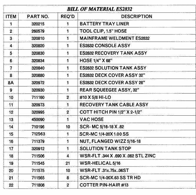
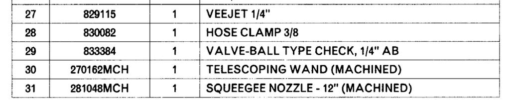
5 EXPLODED VIEWS...23 DRIVE ASSEMBLY...27 SQUEEGEE LIFT MECHINAISM ASSEMBLY 29 PUMP ASSEMBLY...30 IN-LINE FILTER ASSEMBLY...31 MAINFRAME ASSEMBLY...32 CONTROL CONSOLE ASSEMBLY...34 CONTROL BRACKET ASSEMBLY...36 ELECTRICAL BOX SUB-ASSEMBLY & DASHBOARD ASSEMBLY 37 SOLUTION TANK ASSEMBLY...38 RECOVERY TANK ASSEMBLY...39 FIXED LID ASSEMBLY CYLINDRICAL SCRUB DECK ASSEMBLY CYLINDRICAL SCRUB DECK ASSEMBLY DISC SCRUB DECK ASSEMBLY DISC SCRUB DECK ASSEMBLY...48 DECK COVER ASSEMBLY...50 REAR SQUEEGEE ASSEMBLY...51 OFF AISLE WAND ASSEMBLY (optional) 52 SCHEMATICS...55 LIMITED WARRANTY
6 IMPORTANT SAFETY INSTRUCTIONS Operators must read and understand this manual before operating or maintaining this machine. Do not operate this machine in flammable or explosive areas. This machine is designed solely for scrubbing dirt and dust in an indoor environment. Minuteman does not recommend using this machine in any other capacity. The following information below may cause a potential hazard to the operator and equipment. Read this manual carefully and be aware when these conditions can exist. Take necessary steps to locate all safety devices on the machine and train the personnel operating the machine. Report any machine damage or faulty operation immediately. Do not use machine if it is not in proper operating condition. FOR SAFETY DURING OPERATION: Keep hands and feet clear of moving parts while machine is in operation. Make sure all safety devices are in place and operate properly. All covers, doors and latches must be closed and fastened before use. During operation, attention should be paid to other persons in the work area and especially if small children are present. Electric motors and components can cause an explosion when operated near explosive materials or vapor. Do not operate this machine near flammable materials such as solvents, thinners, fuels, grain dust, etc. Store or park this machine on a level surface only, with parking brake engaged. To prevent unauthorized use, machine should be stored or parked with the key removed. This machine is designed for level operation only. Do not operate on ramps or inclines. This machine is not suitable for picking up hazardous dusts. Use caution when moving this machine into areas that are below freezing temperatures. Any water in the tanks or hoses can cause damage to the machine. FOR SAFETY WHEN SERVICING or MAINTAINING MACHINE: 3
7 Stop on level surface. Disconnect the power to the machine by pulling the large red handle (Anderson Plug) located in the back of the machine, mid-right, when charging batteries or during installation or removal of brushes. Avoid moving parts. Do not wear loose jackets, shirts, or sleeves when working on machine. Avoid contact with battery acid. Battery acid can cause burns. When working on or around batteries, wear protective clothing and safety glasses. Remove metal jewelry. Do not lay tools or metal objects on top of batteries. Charging batteries generates explosive gasses. Do not charge batteries when open flames or sparks are present. Do not smoke. Make sure the charger is turned off before disconnecting it from the machine. Charge the batteries in a well-ventilated area with the battery cover removed completely. Do not clean machine with a pressure washer. Authorized personnel must perform repairs and maintenance. Use Minuteman supplied replacement parts. SAVE THESE INSTRUCTIONS 4
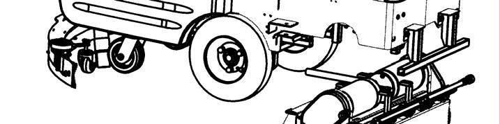
8 INSPECTION Carefully unpack and inspect your ES Walk-Behind Scrubber for shipping damage. Follow unpacking instructions on shipping pallet. Each unit has been tested and thoroughly inspected before shipment. Any damage is the responsibility of the delivery carrier who should be notified immediately. ELECTRICAL This machine is battery operated and designed to operate on 36 volts DC (6) 6-volt batteries. BATTERIES The recommended batteries are rated 275Ah (Minuteman P/N ). We do not recommend mixing AMP hour capacities. Any alternate battery sets can be used if they equal physical size and capacity. See page 13 for service and installation. OPERATOR RESPONSIBILITY Read this manual carefully before operating this machine. The operator is responsible in taking care of the daily maintenance and check ups of the machine to keep it in good working condition. The operator must inform the service mechanic or supervisor when the scheduled maintenance intervals are required as stated in the MAINTENANCE section of this manual. Before starting familiarize yourself with the machine and its controls (see Machine Overview, Front, Machine Overview, Rear, Operator Compartment, Control Console diagrams). MACHINE COMPONENTS FRONT A B C ROLLER BUMPERS RECOVERY TANK SOLUTION TANK I H G D FRONT WHEEL E REAR CASTER F G H REAR SQUEEGEE CONTROL CONSOLE CUP HOLDER J B I VACUUM COVER J TANK LID K DUMP CAP COVER C K F A E D 5


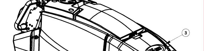
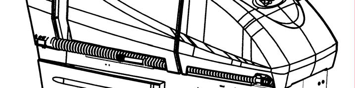
9 MACHINE COMPONENTS REAR A B C CONTROL CONSOLE REAR SQUEEGEE SCRUB DECK A G D SOLUTION DUMP HOSE E F RECOVERY DUMP HOSE ANDERSON PLUG I G H I DIRECTIONAL SWITCH HOUR METER EMERGENCY BELLY BAR F E D H B C MACHINE COMPONENTS CONTROL CONSOLE A ACCELERATION LEVER E D B C SPEED CONTROL KNOB DIRECTIONAL LEVER A C D E F G DIRECTIONAL INDICATOR KEY SWITCH EMERGENCY BELLY BAR OFF-AISLE WAND SWITCH I J B A H I J BATTERY GAUGE SOLUTION CONTROL MODE SELECTOR F H G 6
10 THE CONTROL CONSOLE For operator ergonomics, the control console houses all the primary function buttons are grouped in a central area. The key switch, main keyboard, directional switch and off-aisle wand switch are clustered in the back area. The directional switch (forward and reverse) is located in front of the console for easy fingertip operation. Accelerator Lever (A) Enables the machine to move forward or backwards once depressed. Speed Control (B) This knob controls the rate at which the machine moves. Turning the knob clockwise will increase the speed. Turning the knob counter-clockwise will decrease the machine speed. Directional Switch (C) When you flip the switch down, the machine moves backwards or flip the switch upward, the machine will go forward. Directional Indicator (D) This indicator displays which direction the ES 2832 will travel once the Accelerator Lever is depressed. A light is available for each direction. Amber when set to forward. Red when set to reverse. Key switch (E) Controls the machine s power (On/Off) with a key for safety. All operational settings are retained even when the power is turned off and on. This also serves as a reset switch when error or fault codes. Emergency Belly Bar (F) If this bar is to be depressed it will override the directional switch and force the ES 2832 to go forward. Most useful if backed into a corner or object to prevent from pinching the operator. Off-aisle wand switch (G) On/Off control for the water supply to the wand and vacuum motor. If the switch is in the On position it will force the battery gauge to blink 6 LEDs to signify the wand is currently on. Battery Gauge (H) This gauge displays the remaining battery life. The gauge has a readout of 10 LEDs. 3 Green, 4 Amber, 3 Red. This gauge will also display the fault code if the system has an error represented by the number illuminated flashing LEDs. See Fault/Diagnostics Codes below for specific code. If the battery life is low the battery gauge bar icon will be flashing to signal the operator that the machine is almost out of power. Once this signal is displayed to the operator, all functions will shut off including the transport mode. The operator has to turn the key switch OFF and then, ON to reset the machine. The machine then will only have a few minutes left of reserve power for a short Vacuum only mode to pick up remaining solution on the floor and Transport power. Solution Control (I) This knob controls the rate at which solution is put down. Turning the knob clockwise will increase the amount of solution put down. Turning the knob counter-clockwise will decrease the solution rate. The knob can be adjusted between 0.25 gpm up to 1.1 gpm. Mode Selector (J) This switch will toggle between one of the five cleaning modes available on the ES
11 CLEANING MODES 1. REGULAR SCRUB MODE When the machine is running in this mode, the machine will perform all operations. This mode can be used for day-to-day tasks under normal conditions. When the operator sets the directional switch to forward and activates the accelerator handle, the solution pump will turn on, the brushes will turn on and be lowered to the floor, as well as the rear squeegee. While operating in this mode, the solution will be dispersed into the brushes, which will scrub the floor allowing the chemical in the solution to break down the dirt on the floor. As the machine continues to move forward, the rear squeegee and vacuum system will recover the dirt and dispensed solution. If the operator stops moving, the machine will automatically raise the scrub deck and turn off the brushes. If the directional switch is changed to reverse the machine will continue to operate normally, only the rear squeegee will raise up. 2. HEAVY SCRUB MODE This mode is similar to Regular Scrub. The machine will continue to operate the same was as if it was in Regular Scrub Mode, only this mode applies more solution and brush pressure is increased. This mode is used for high traffic areas and areas that have been heavily soiled, but do not require time for the solution to soak. 3. DOUBLE SCRUB MODE When the machine is running in this mode, the machine will perform all operations except dirty solution recovery. This mode can be used if the floor is heavily soiled and the chemical will need additional time to emulsify grease and oils that are on the floor. When the operator sets the directional switch to either the forward or reverse position and activates the accelerator lever, the solution pump will turn on, the brushes will turn on and be lowered to the floor. While operating in this mode, the solution will be dispersed into the brushes, which will scrub the floor allowing the chemical in the solution to break down the dirt on the floor. As the machine continues to move forward or back, the rear squeegee and vacuum system are not on, which allows the solution to stay on the floor emulsifying the grease and oil. If the operator stops moving in either direction, the machine will automatically raise the scrub deck and turn off the brushes. After double scrubbing, the operator should use the vacuum only mode to recover the dirty solution water from the floor. 8
12 4. VACUUM ONLY MODE When the machine is running in this mode, the machine will only lower the rear squeegee and turn on the vacuum system to recover the dirty solution from the floor. This mode is usually chosen after double scrubbing to recover the dirty solution but it can also be used to pick up spills. When the operator sets the directional switch to forward, the rear squeegee will be lowered to the floor as the vacuum turns on, pulling the dirty solution water from the rear squeegee into the recovery tank. If the operator stops moving forward and sets the directional switch to reverse, the rear squeegee will retract (protecting it from damage) and the vacuum motor will turn off after a few seconds. If the operator quits moving in either direction, the machine will automatically raise the squeegee and turn off the vacuum motor after a few seconds. 5. TRANSPORT MODE When the machine is set in this mode, none of the cleaning functions of the machine will operate. This mode is only used to transport the machine from one location to another at a faster rate of speed. 6. WATER FLOW Located on the left side of the control console. This knob controls the rate at which water / solution is distributed to the scrub deck. The farther the knob is turned clockwise the more water will be distributed. 7. SPEED CONTROL Located on the right side of the control console. This knob controls the propelling speed of the machine. The farther the knob is turned clockwise the faster the machine will travel. As discussed earlier, the directional switch governs the direction of travel the machine will take. OPERATION OF CONTROLS POWER SAVE MODE The ES 2832 is equipped with a power save feature to conserve battery power. If the key switch power is left ON and none of the controls are activated for a period of fifteen minutes, the ES 2832 automatically goes into power down mode and turns OFF the power to conserve your batteries in case the operator forgets to turn the key switch off or leaves the machine unattended. 9

. Each main component is individually protected with an internal breaker built-in the controller.")

13 EMERGENCY DISCONNECT HANDLE This handle is located beneath the control console off center to the right. When the red emergency handle is pulled, power will be turned off. Use this button in case of a machine emergency. To reactivate, return the handle back to its original position, correctly seated in the receptacle. All operational settings are retained even when the power is turned off and on. CIRCUIT BREAKER The circuit breaker is located under the emergency belly bar. The 100-amp breaker protects the main system circuit (controller). Each main component is individually protected with an internal breaker built-in the controller. (See fault code table) and can be reset by turning the key switch off a few seconds and then on again. BATTERY COMPARTMENT The battery compartment is located on the rear of the machine under the recovery tank. Unlatching the two safety latches on the side of the machine enables the operator to tilt the recovery tank and access the batteries for servicing and maintenance (make sure recovery tank has been drained before tilting). The battery compartment contains six 6-volt batteries connected in series. Connect the batteries according to the battery connection diagram (see diagram). The recommended batteries are 275Ah (Minuteman P/N ). 10
.")
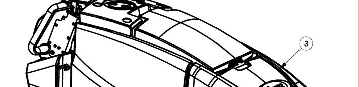
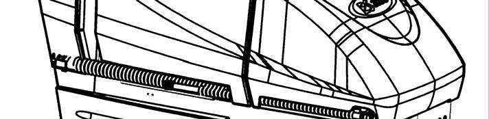
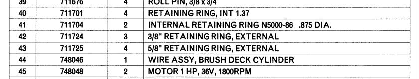
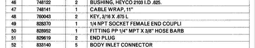
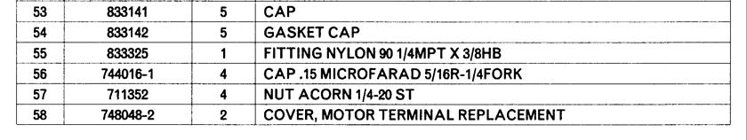
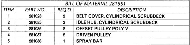
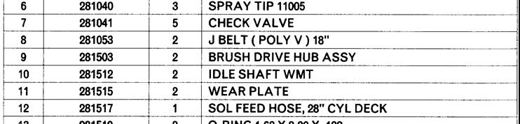
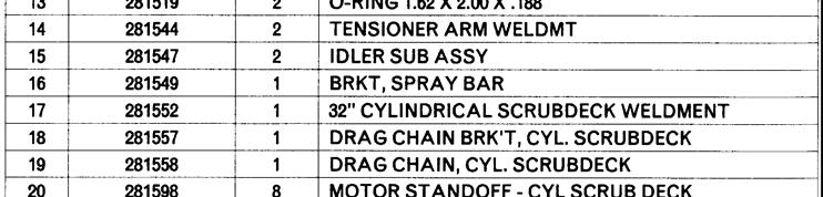
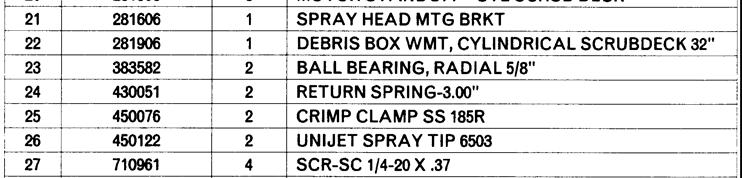
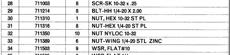
14 SCRUB DECK Minuteman offers two deck types (Cylindrical and Disc) to fit your specific needs. The ES2832 design is very dynamic wherein the decks are interchangeable in a matter of minutes whenever necessary (removal of four bolts, and two quick-connects). The cylindrical brush deck has five built-in spray jets to uniformly dispense cleaning solution on the floor and a wet sweeping debris tray to collect loose objects on the floor. The disc brush deck dispenses cleaning solution through the center hub and contained within the bristle area for efficient agitation of cleaning solution to the floor and channeled to the rear of the machine. The disc brushes are also easily removed and installed with the quick release clamp by using any of the three access doors. Another nice feature that these scrub decks have is the ability to have uniform brush pressure applied to the floor at all times. Since the scrub deck brush pressure is computer controlled, it will automatically adjust and compensate to uneven contours on the floor while maintaining brush pressure. CYLINDRICAL SCRUB DECK A B C D E F G H I J K L M Housing Spray jets (5) Access door (2) Nut, Access door Debris box Connector, water Mounting bracket Connector, power Brush motor (2) Pulley cover (2) Bolt (4) Lock washer (4) Flat washer (4) 11

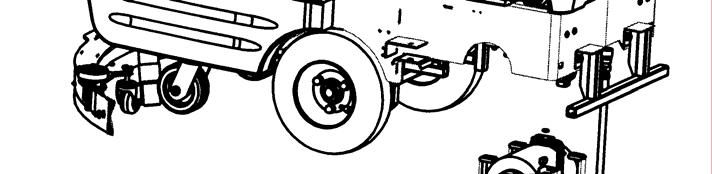
15 DISC SCRUB DECK A B C D E F G H I Housing Access door (6) Brush skirt Brush motor Mounting bracket Flat washer (4) Lock washer (4) Bolt (4) Connector, power Connector, water J SCRUB DECK INSTALLATION When installing a cylindrical scrub deck to a machine: Install brushes after the deck has been mounted to avoid flat spots on the brushes. Use a piece of cardboard underneath the deck to prevent scratches to the painted surface when sliding the deck under the machine. Make sure the scrub deck is oriented correctly with the spray jets towards the front of the machine. When installing a disc scrub deck to a machine: Install brushes on the scrub deck; this aids the installer in sliding the deck assembly into position. Make sure the scrub deck is oriented correctly with the solution hose tee fitting towards the front of the machine. INSTALLATION INSTRUCTIONS Park the machine on a flat or level surface. Remove the 2 pins that fasten the deck cover on the machine. Turn the key switch to the ON position and select the transport mode on the dashboard. Slide the scrub deck assembly underneath the machine (follow instructions as described above). Position the scrub deck to align the mounting brackets with the mounting lugs on the lift linkage. Lower the lift linkage to the floor by pressing the raise/lower deck button. Lower the lift linkage mounting lugs until they barely touch the scrub deck mounting brackets. Fasten with the four (4) bolts, flat washer and lock washer. For cylindrical scrub deck only: 12
16 Remove the two access doors (one each end) by removing the (3) nyloc nuts. Install the brushes by sliding through the access opening. Align the notches on the brush with the drive pins on the hub. Push brush all the way until it bottoms out. Insert access door hub to the other end of brush. Reinstall nuts and tighten. 13


 C. Swivel Caster (2) D. Lock Nut E. Turnbuckle F. Front squeegee blade G. Wing bolt (2) H. Toggle clamp I. Front strap (long) J.")
17 REAR SQUEEGEE The rear squeegee is the main element that acts as the conduit that transfers the spent solution into the recovery tank. A daily maintenance check of this component is essential to have optimum machine performance. The rear squeegee assembly is equipped with a universal front blade that allows the operator the option to use a slotted and a non-slotted side for specific applications. Each blade configuration has two usable edges. The rear blade however has four usable edges. The squeegee is pre-adjusted at the factory. Adjustments may be required to get optimum performance for different floors and conditions. G Q N E D I H J C P O B G A L M K REAR SQUEEGEE COMPONENTS A. Rear squeegee blade B. Wing jam nut (2) C. Swivel Caster (2) D. Lock Nut E. Turnbuckle F. Front squeegee blade G. Wing bolt (2) H. Toggle clamp I. Front strap (long) J. Front strap (short) K. Rear strap (latch side) L. Rear strap (catch side) M. Latch N. Guide wheels (2) O. Nylon wing bolt (2) P. Nylon bolt (2) Q. Recovery hose intake 14
18 REAR SQUEEGEE ADJUSTMENT Ensure that the scrubber is on a relatively flat surface. Turn on the key switch and select the Vacuum only mode. This lowers the squeegee to the floor and turns the vacuum motor on. Move the scrubber one or two feet forward slowly while someone behind the machine checks the rear squeegee blade (item A) for uniform deflection to the floor. If uneven deflection or lay is evident, minor adjustments may be necessary to avoid streaking and uneven wear on the blade. To correct this, loosen the wing jam nut (item B) in order to adjust the caster height. If the squeegee blade is deflecting too much, the casters (item C) need to be lowered to control the down pressure. Lower the caster by turning the exposed threaded stem on the caster clockwise. Make the adjustment a few turns at a time. Repeat step 2. If the blades are not deflecting enough, raise the caster by turning the stem counter-clockwise to adjust the caster height to allow more down pressure on the squeegee. Repeat step 2. Make sure there is even deflection on the entire length of the rear blade. Adjust the casters and retighten the wing jam nuts to lock the caster setting in place. Pitch adjustment is necessary if the outer ends on the squeegee blade do not contact the floor and there is too much deflection in the middle area or if the outer ends are over deflected and there is no contact in the middle. To adjust the pitch, repeat step 2. Loosen the lock nut (item D) in the turnbuckle assembly. Turning the turnbuckle (item E) clockwise or counter-clockwise controls the forward and backward pitch of the squeegee. Having the rear blades deflected uniformly along its entire length is the desired set-up. Repeat step 2 until desired set-up is achieved. In certain applications where a non-slotted front wiper blade (item F) is needed, detach the rear squeegee assembly by loosening the two wing bolts (item G). Unlock the toggle clamp (item H) on the front squeegee to release the front long strap (I) and slide the front short strap (item J). Flip the blade over to the non-slotted side. Reattach the straps and lock the clamp back in place. You can also easily replace the rear blade by unlatching the latch (item M) and removing the two rear straps (items K & L) by sliding them off the assembly. You can then flip the blade over in order to use a new edge for better wiping action. 15

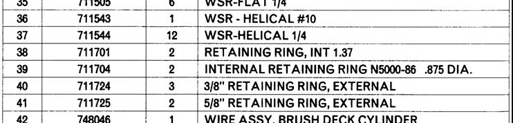
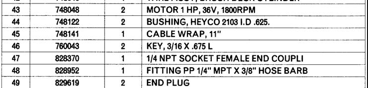
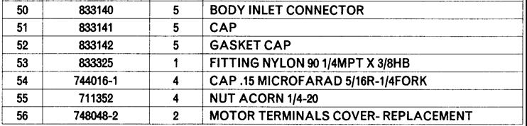
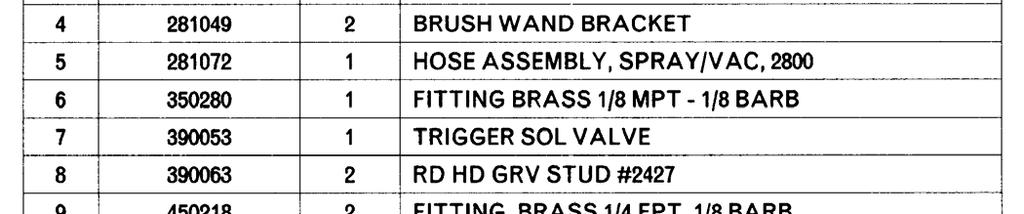
19 OFF-AISLE WAND (optional) The ES2832 is equipped with a ready-to-use built-in telescoping off-aisle wand system for use in hard to reach areas. This integrated system eliminates attaching hose for use and detaching hoses for storage. By turning the pump switch ON (located behind the right handle of the control console) the off-aisle wand is ready to use in seconds. After use, simply flip the switch OFF and return the wand to it s original storage location. The wand is also equipped with the patented flip-flop tool that allows the operator to switch from scrub brush to squeegee tool by just rotating the tool end. OFF-AISLE WAND TOOL The off-aisle wand tool as described in the previous page is composed of the following items: The recovery hose is connected to the end of the wand on one end and to the recovery tank hose on the other end. This hose has swivel cuffs on both ends that allow the operator a good range of motion and the solution hose to be inside the recovery hose. The trigger controls the solution flow to the spray jet. Squeezing the trigger opens an internal valve to dispense cleaning solution. The coiled solution hose acts as a conduit from the trigger to the spray jet, and allows hose to be extended along with the wand. The spray jet dispenses the cleaning solution to soak soiled areas that are not accessible to the main scrub deck. The telescoping wand allows the length to be adjusted for operator comfort and better storage when not in use. Sliding the wand extender forward (as shown above) extends the wand length during use and retracts the wand by pulling it back for the storage position. The flip-flop tool gives the operator complete flexibility when changing from the scrub brush mode to vacuum squeegee mode by simply rotating the end. When the off-aisle wand switch is turned ON, six LEDs on the battery gauge will flash to indicate that you are in the off-aisle tool mode. This switch turns on the pump to supply solution to the wand spray jet and the vacuum motor to recovery the dirty water. 16
20 THE ES2832 This machine was designed with total operator comfort and ease of use in mind. All machine components have been designed as a total system to efficiently clean dirty floors. The ES2832 has four available scrub head types and sizes to fit specific applications. Please contact your Minuteman representative for specific recommendations for the correct scrub head type, size, and brush type and chemical applications. Before using the machine, always perform the following steps to ensure proper machine operation. Check under the machine for leaks. Check the rear squeegee for wear and damage. Check the solution and recovery tank levels. After using the machine, always perform the following steps: Check the battery charge level. Charge batteries if necessary. When charging batteries, extra precaution is required: Battery acid can cause burns. When working on or around batteries, always wear protective clothing and safety glasses. Remove metal jewelry. Do not lay tools or metal objects on top of the batteries. Charging batteries generate explosive gasses. DO NOT CHARGE BATTERIES WHEN OPEN FLAMES OR SPARKS ARE PRESENT. DO NOT SMOKE. Make sure the charger is turned off before disconnecting it from the batteries. Charge the batteries in a well-ventilated area. Fluid levels should be checked before and after charging and maintained at the proper levels. If low, add distilled water until the metal plates are covered. If the machine is not used for an extended period of time, batteries should be kept fully charged with a boost charge once a week. Check for wire, string, or twine wrapped around the scrub brushes. Check the rear squeegee for wear and damage. Check the rear squeegee suction hose and off-aisle wand hose for obstructions. Empty and clean the debris box (cylindrical systems only). Drain and clean the recovery tank. Check under the machine for leaks. Check the service records to determine maintenance requirements. WARNING! Be sure you understand the machine controls and their functions. While on ramps or inclines, avoid sudden stops when tanks are filled. Avoid abrupt sharp turns. Slow down driving speed when going downhill. MACHINE OPERATION Follow the instructions in preparing the machine for use as described in this manual. Turn the Key switch ON (I). The Battery Gauge will light up for a few seconds then display the Battery Condition. Do NOT attempt to operate during this time. Select one of the five available Modes on the Control Console for the required task. Refer to the Main Keyboard section of this manual for a complete description of the functions. Determine the direction you need to travel by selecting forward or reverse on the Directional Switch. Vary the acceleration knob to propel the machine at the desired speed. Squeezing the Accelerator Handle turns on the Transport, Brushes, Water Flow, Vacuum and lowers the Rear Squeegee accordingly to the Mode selected. If the operator triggers the accelerator handle before, or turns the key switch ON at the same time, the machine will not move as a safety precaution. 17
21 Simply release the handle and squeeze the handle again to drive the machine. Please refer to the Main Keyboard section of this manual for a complete description of the functions. When Reverse is selected on the Directional Switch, the Rear Squeegee automatically is raised. However, the Scrub brushes will continue to rotate and solution will continue to flow. Start scrubbing by driving the machine forward in a straight line at 3/4 speed and overlap each path by 2 to 3 inches. Adjust your speed and solution flow according to the condition of the floor. When scrubbing, check behind the machine occasionally to see that all the dirty water is being picked up. If streaking occurs, your Water Flow setting may be too high, the Recovery Tank may be full, the Squeegee hose may be clogged, or the Rear Squeegee may require some adjustment or cleaning. Make the necessary adjustments on the Rear Squeegee if streaking occurs both in straight paths and in turns. Please refer to the Rear Squeegee section of this manual before making any adjustments. The recovery tank has an overflow protection to guard against water from entering the vacuum system when the recovery tank is full. A ball float shut-off system has been integrated into the Recovery Tank. When the dirty water reaches a certain level, the ball gets suctioned into the vacuum manifold and blocks the airflow thus, preventing the machine from picking up more liquid. When this happens, the operator is then required to stop scrubbing and empty the recovery tank. To stop scrubbing, select the Transport mode. This will automatically stop the Solution Flow, raise the Scrub deck, and raise the Rear squeegee (there is a 15 second delay for the vacuum motor and a 8 second delay on the rear squeegee). Drive the ES to a designated dirty water disposal area and empty the Recovery tank. To empty, remove the Drain hose from its storage hanger. Unscrew the plug and hold the hose end above the water level in the tank to avoid sudden, uncontrolled flow of dirty water. With the plug completely off, carefully direct the water flow to the desired drain. Reinsert the plug and tighten and return to its storage hanger. The recovery tank should be rinsed out to remove solids in the tank. Open the Cleanout cap to remove the Stopper plug. Tilt the recovery tank (similar to accessing the batteries) and clean the sludge that has settled in the sump area by either back flushing or by scraping it out. Be sure to tightly secure the Stopper plug and cleanout cap before continuing to operate the scrubber. Refill the solution tank and continue scrubbing until the job is done or when the machine runs out of power. The battery gauge bar icon will flash to signal the operator that the machine is almost out of power. Once this signal is displayed to the operator, all functions will shut off (brush will turn off and the scrub deck will raise up, water flow will cease, the rear squeegee will raise up and the vacuum motor will turn off) including the transport mode. The machine then will only have a few minutes left of reserve power for a short Vacuum only mode to pick up remaining solution on the floor and Transport power to drive to the battery recharging station. AFTER USE: When finished scrubbing, select the Transport mode, all functions will shut off (brush will turn off and the scrub deck will raise up, water flow will cease, the rear squeegee will raise up and the vacuum motor will turn off). Drive the machine to a service area for daily maintenance and review items that may need service. Empty the solution tank, by opening the solution hose valve into a drain. Rinse the tank with clean water to prevent any build-up of dried up chemicals that could cause clogging in the plumbing. Empty the recovery tank as described on line 11 and 12. Remove the brushes or pad holders and rinse them in warm water and hang to dry. Remove the rear squeegee, rinse with warm water and reinstall after cleaning. Check the maintenance schedule on the next page and perform any required maintenance before storing the machine. 18
22 Store the machine indoors in a clean dry place. Keep from freezing. Leave solution and recovery tank lids open for ventilation to prevent odor build-up. Turn Key switch OFF (O) and remove key. MAINTENANCE SCHEDULE Daily Weekly Monthly Yearly Charge Batteries Check Each Battery Cell(s) Water Level Lubrication Grease Fittings, chains, etc. Check Carbon Brushes Check/Clean Tanks & Hoses Inspect Scrub Housing Skirts Check/Clean/Rotate the Brushes/Pads Inspect and Clean Solution Filter Check/Clean the Squeegee Clean Spray jets on Cylindrical System Check/Clean Vacuum Shut-Off Float Check/Clean the Vacuum Motor Foam Filter Clean Hopper on Cylindrical System Have Minuteman check the vacuum motor carbon motor brushes once a year or after 300 operating hours. The brush motor carbon brushes should be checked every 500 hours or once a year. NOTE: Refer to the Service Manual for more detail on maintenance and service repairs. LUBRICATING THE MACHINE Regularly scheduled lubrication of certain machine parts should be performed to insure trouble-free operation of the machine. Apply a generous amount of grease into the fittings on the machine until grease seeps out around the bearings. The grease points are listed below: Rear squeegee caster wheel axle (2) Rear squeegee caster wheel stem (2) Apply lubricant or light machine oil to lubricate the: Rear squeegee general pivot points Scrub deck linkages Drive wheel assembly seals. 19
23 GENERAL MACHINE TROUBLESHOOTING Problem Possible Cause Remedy Worn or torn squeegee blades Rotate or replace blades Poor water pick-up Squeegee out of adjustment Adjust so blades touch floor evenly across entire width Recovery tank full Empty recovery tank Recovery tank drain hose leak Secure drain hose cap or replace Recovery tank lid gasket leak Replace gasket lid cover properly Debris caught in squeegee Clean squeegee Vacuum hose clogged Remove debris and flush hose Using too much solution Adjust solution control valves Vacuum hose to squeegee or recovery tank Reconnect or replace squeegee hose disconnected to squeegee or damaged Worn brushes Rotate or replace brushes Poor scrubbing performance Wrong brush or cleaning chemical Consult Minuteman Debris caught on scrub brushes Remove debris Moving machine too fast Slow down Not using enough solution Adjust solution flow setting Low battery charge Recharge batteries 3 Bars Flashing on Battery Indicator Reduce scrub brush pressure. Broken brush drive belts on cylindrical system, replace belt(s). Check power connection. Reconnect plugs. Reset machine: Turn key switch off and restart. Solution tank empty Fill solution tank Inadequate solution flow or no Recovery tank full Empty recovery tank solution to the floor Solution lines, valves, filter or spray jets Flush lines, and clean solution filter and clogged spray jets. Solution solenoid valve Clean or replace valve No solution to off-aisle wand Recovery tank full Empty recovery tank spray jet Solution tank empty Refill solution tank Main system controller Check error fault codes (See service manual) Machine does not run Tripped 100 amp circuit breaker Check for electrical short circuit Reset machine: Reset and turn key switch off and restart. No FWD/REV drive Drive system speed controller. 2 bars flashing on battery indicator. Check error fault codes (See service manual) Reset machine: Turn key switch off and restart. Emergency stop switch tripped Activate switch by turning as indicated by arrows. Recovery tank full Empty recovery tank Excessive foaming in recovery tank. Empty recovery tank. Vacuum motor does not turn on Use less or change chemical. Use defoaming agent. 5 bars flashing on battery indicator. Check for motor overload. Reset machine: Turn key switch off and restart. Debris box full Empty and clean debris box Poor sweeping performance Brushes worn Replace brushes (Cylindrical System) Bristles have taken a set Rotate brushes 20

24 ES 2832 FAULT / DIAGNOSTIC CODES Scrubber System Faults External to TRIO+ LED Readout Code Fault Description Corrective Action 1 2C00 LOW BATTERY ERROR Battery Charge to low. Recharge battery. 1 2C01 LOW BATTERY ERROR2 Battery Charge to low. Recharge battery. 1 2C02 SOFT BATTERY LOCKOUT OCCURRED Battery Charge to low. Recharge battery. 1 2C03 SOFT BATTERY LOCKOUT 2 OCCURRED Battery Charge to low. Recharge battery TRACTION MOTOR FAULT-1 Disconnect Battery for 60 seconds. Reconnect battery TRACTION MOTOR OVER CURRENT ERROR Disconnect Battery for 60 seconds. Reconnect battery SOFT TRACTION MOTOR IN Traction Motor being overloaded or Foldback FOLDBACK STATE parameters set too low MOTOR LINE VOLTAGES INSTABILITY Disconnect Battery for 60 seconds. Reconnect battery TIMEOUT TRACTION SPEED INPUT OUT OF RANGE SOFT BRUSH MOTOR DISCONNECTED ERROR SOFT BRUSH CURRENT FOLDBACK SOFT BRUSH CURRENT FOLDBACK SOFT BRUSH CURRENT FOLDBACK SOFT BRUSH INHIBIT BRUSH STARTUP OVERCURRENT DETECTION 21
25 SOFT VACUUM MOTOR DISCONNECTED ERROR SOFT VACUUM CURRENT FOLDBACK SOFT VACUUM CURRENT FOLDBACK SOFT VACUUM CURRENT FOLDBACK TILLER FAULT-1 For all Tiller Diagnostic Codes: TILLER MAX WIPER DIFFERENCE ERROR TILLER MAX PULL DOWN DIFFERENCE ERROR TILLER MAX PULL SAFE DIFFERENCE ERROR TILLER REFERENCE ERROR TILLER LO REFERENCE ERROR TILLER HI REFERENCE ISO ERROR TILLER LO REFERENCE ISO ERROR 1- Check throttle wiring for shorts or opens. Repair or replace as necessary. 2- If Diagnostic Code is not cleared, then replace throttle TILLER ERROR BOTH HAVE READINGS EXCESSIVE CURRENT TRIP Disconnect Battery for 60 seconds. Reconnect battery SOFT AUX1 OVERCURRENT Device connected to Aux-1 exceeded current limit. OCCURRED Check wiring or replace device SOFT AUX2 OVERCURRENT Device connected to Aux-2 exceeded current limit. OCCURRED Check wiring or replace device SOFT AUX3 OVERCURRENT Device connected to Aux-3 exceeded current limit. OCCURRED Check wiring or replace device SOFT AUX4 OVERCURRENT Device connected to Aux41 exceeded current limit. OCCURRED Check wiring or replace device SOFT BRAKE LIGHT OVERCURRENT Brake light circuit exceeded current limit. Check wiring OCCURRED or replace device C SOFT ALARM OVERCURRENT Alarm circuit exceeded current limit. Check wiring or OCCURRED replace device AUX1 OVERCURRENT 2 OCCURRED Device connected to Aux-1 exceeded current limit. Check wiring or replace device AUX2 OVERCURRENT 2 OCCURRED Device connected to Aux 2 exceeded current limit. Check wiring or replace device ERROR AUX 1 POSITIVE Check Aux-1 wiring and device connected to Aux-1. SHORTED_LOW Repair or replace as necessary ERROR AUX 1 NEGATIVE SHORTED Check Aux-1 wiring and device connected to Aux-1. LOW Repair or replace as necessary ERROR AUX 2 POSITIVE SHORTED Check Aux-2 wiring and device connected to Aux-2. LOW Repair or replace as necessary ERROR AUX 2 NEGATIVE SHORTED Check Aux-2 wiring and device connected to Aux-2. LOW Repair or replace as necessary EMERGENCY STOP ERROR Disconnect Battery for 60 seconds. Reconnect battery BRAKE FAULT 2 Check Brake circuit wiring and brake. Repair or replace as necessary BRAKE OVER CURRENT ERROR Check Brake circuit wiring and brake. Repair or replace as necessary HIGH BATTERY ERROR Battery is overcharged or damaged. Replace battery. Ripple 2F01 TILLER DISPLACED ERROR Throttle displaced on Power-up. Release throttle and then re-engage throttle. Ripple 7901 SOFT BELLY BUTTON ACTIVATED Disconnect Battery for 60 seconds. Reconnect battery 22


26 EXPLODED VIEWS 23

27 24
28 25
29 26
30 DRIVE ASSEMBLY 27
31 28
32 SQUEEGEE LIFT MECHANISM ASSEMBLY 29

33 PUMP ASSEMBLY 30


34 IN-LINE FILTER ASSEMBLY 31
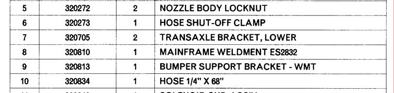
35 MAINFRAME ASSEMBLY 32
36 33
37 CONTROL CONSOLE ASSEMBLY 34

38 35


39 CONTROL BRACKET ASSEMBLY 36


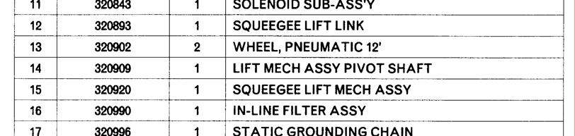
40 ELECTRICAL BOX SUB-ASSEMBLY & DASHBOARD ASSEMBLY 37
41 SOLUTION TANK ASSEMBLY 38
42 RECOVERY TANK ASSEMBLY 39
43 40
44 FIXED LID ASSEMBLY 41
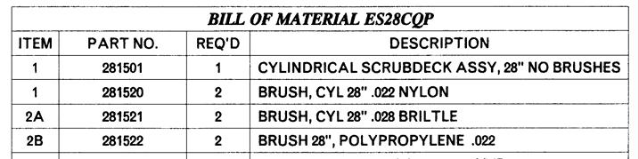
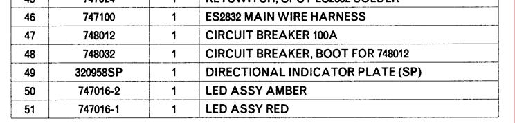
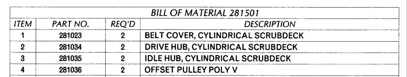
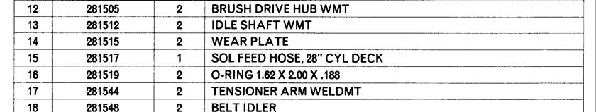
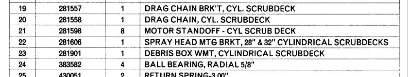
45 28 CYLINDRICAL SCRUB DECK ASSEMBLY 42
46 43
47 32 CYLINDRICAL SCRUB DECK ASSEMBLY 44
48 45
49 28 DISC SCRUB DECK ASSEMBLY 46
50 47
51 32 DISC SCRUB DECK ASSEMBLY 48
52 49


53 DECK COVER ASSEMBLY 50
54 REAR SQUEEGEE ASSEMBLY 51
55 OFF AISLE WAND ASSEMBLY (optional) 52
56 53
57 54
58 SCHEMATICS 55
59 56
60 57
61 58
62 59
63 LIMITED WARRANTY Minuteman International, Inc. warrants to the original purchaser/user that this product is free from defects in workmanship and materials under normal use and service for a period of three years from date of purchase. In addition, Minuteman International, Inc. will, at its option, honor labor warranty claims for the first 36 months from date of sale, provided such claims are submitted through and approved by factory authorized repair stations. Minuteman International, Inc. will, at its option, repair or replace without charge, except for transportation costs, parts that fail under normal use and service when operated and maintained in accordance with the applicable operation and instruction manuals. This warranty does not apply to normal wear, or to items whose life is dependent on their use and care, such as belts, cords, switches, hoses, rubber parts, electrical motor components or adjustments. Parts not manufactured by Minuteman International, Inc. such as engines, batteries, battery chargers, hydraulic pumps, and tires are covered by and subject to the warranties and/or guarantees of their manufacturers. Please contact Minuteman International, Inc. for procedures in warranty claims against these manufacturers. Special warning to purchaser -- Use of replacement filters and/or pre-filters not manufactured by Minuteman International, Inc. or its designated licensees, will void all warranties expressed or implied. A potential health hazard exists without exact original equipment replacement. All warranted items become the sole property of Minuteman International, Inc. or its original manufacturer, whichever the case may be. Minuteman International, Inc. disclaims any implied warranty, including the warranty of merchantability and the warranty of fitness for a particular purpose. Minuteman International, Inc. assumes no responsibility for any special, incidental or consequential damages. This limited warranty is applicable only in the U.S.A. and Canada, and is extended only to the original user/purchaser of this product. Customers outside the U.S.A. and Canada should contact their local distributor for export warranty policies. Minuteman International, Inc. is not responsible for costs or repairs performed by persons other than those specifically authorized by Minuteman International, Inc. This warranty does not apply to damage from transportation, alterations by unauthorized persons, misuse or abuse of the equipment, use of noncompatible chemicals, or damage to property, or loss of income due to malfunctions of the product. If a difficulty develops with this machine, you should contact the dealer from whom it was purchased. This warranty gives you specific legal rights, and you may have other rights which vary from state to state. Some states do not allow the exclusion or limitation of special, incidental or consequential damages, or limitations on how long an implied warranty lasts, so the above exclusions and limitations may not apply to you. World Headquarters Minuteman Canada, Inc. Minuteman International, Inc Drew Road 111 South Rohlwing Road Mississauga, Ontario Addison, Illinois L5S 1B1 (630) (905) Form FAX (630) FAX (905) Printed in U.S.A. 04/04 60
Electronic Service Manuals
 Electronic Service Manuals This electronic document is provided as a service to our customers. We do not create the contents of the information contained in this document. Should you have detailed questions
Model #: ES320 Floor Scrubber Traction Driven E320QP E320CE E320QPIW OPERATION SERVICE PARTS CARE
 ES320 Floor Scrubber Traction Driven Model #: E320QP E320CE E320QPIW OPERATION SERVICE PARTS CARE TABLE OF CONTENTS IMPORTANT SAFETY INSTRUCTIONS...1 FOR SAFETY DURING OPERATION:...1 FOR SAFETY WHEN SERVICING
Lumina 28 Traction Drive Model: Battery Burnisher M28036TDQP OPERATION SERVICE PARTS CARE
 Lumina 28 Traction Drive Model: Battery Burnisher M28036TDQP OPERATION SERVICE PARTS CARE Table of Contents IMPORTANT SAFETY INSTRUCTIONS...1 OPERATING INSTRUCTIONS...2 INSPECTION...2 ELECTRICAL...2 BATTERIES...2
SCV 24/26 RIDER SCRUBBER OPERATION SERVICE PARTS CARE
 SCV 24/26 RIDER SCRUBBER OPERATION SERVICE PARTS CARE This manual is furnished with each new MINUTEMAN SCV TM 24/26. This provides the necessary operating and preventive maintenance instructions. Operators
User Manual. H20 Walk-Behind Scrubber Disc Traction Drive
 User Manual H20 Walk-Behind Scrubber Disc Traction Drive This manual is furnished with each new MINUTEMAN H20. This provides the necessary operating and preventive maintenance instructions. Operators must
Electronic Service Manuals
 Electronic Service Manuals This electronic document is provided as a service to our customers. We do not create the contents of the information contained in this document. Should you have detailed questions
User Manual. Phoenix 20 Floor Scrubber Traction Drive
 User Manual Phoenix 20 Floor Scrubber Traction Drive This manual is furnished with each new PowerBoss Phoenix 20. This provides the necessary operating and preventive maintenance instructions. Operators
Parts and Instructions Manual SCV 28/32 Rider Scrubber
 Parts and Instructions Manual SCV 28/32 Rider Scrubber This manual is furnished with each new MINUTEMAN SCV TM 28/32. This provides the necessary operating and preventive maintenance instructions. Operators
User Manual. PHX26ECO Walk-Behind Scrubber Traction Drive Disc Deck
 User Manual PHX26ECO Walk-Behind Scrubber Traction Drive Disc Deck This manual is furnished with each new POWERBOSS PHX26ECO. This provides the necessary operating and preventive maintenance instructions.
User Manual. Max Ride 26 Rider Scrubber Disc Traction Drive
 User Manual Max Ride 26 Rider Scrubber Disc Traction Drive Preface Preface This manual is furnished with each new MINUTEMAN Max Ride 26. This provides the necessary operating and preventive maintenance
Lumina 20 Battery Burnisher. Model: M26036QP M26036CE OPERATION SERVICE PARTS CARE. Revised 8/04
 Lumina 20 Battery Burnisher Model: M26036QP M26036CE OPERATION SERVICE PARTS CARE Revised 8/04 Contents Illustration, Spare Parts, Operation, and Service Precautions... 1 Operating Instructions... 2 Inspection...
User Manual. E Ride 28/32 SPORT Rider Scrubber
 User Manual E Ride 28/32 SPORT Rider Scrubber Technical Specifications This manual is furnished with each new MINUTEMAN ERide 28/32 SPORT. This provides the necesary operating and preventive maintenance
Parts and Instruction Manual ES 2832 Walk-Behind Scrubber
 Parts and Instruction Manual ES 2832 Walk-Behind Scrubber This manual is furnished with each new MINUTEMAN ES TM 2832. This provides the necessary operating and preventive maintenance instructions. Operators
Electronic Service Manuals
 Electronic Service Manuals This electronic document is provided as a service to our customers. We do not create the contents of the information contained in this document. Should you have detailed questions
FLOORMASTER 18B OPERATING & MAINTENANCE READ THIS BOOK
 FLOORMASTER 18B INTRODUCTION OPERATING & MAINTENANCE INSTRUCTIONS This operator s book has important information for the use and safe operation of this machine. Read this book carefully before starting
User Manual. Admiral 28/32 Rider Scrubber
 User Manual Admiral 28/32 Rider Scrubber Technical Specifications This manual is furnished with each new POWERBOSS Admiral 28/32. This provides the necesary operating and preventive maintenance instructions.
Service Manual. For the SCV2832E, SCV2426, Automatic Scrubbers For: Training Troubleshooting
 Service Manual For the SCV2832E, SCV2426, SCV280000 & ES2832 Automatic Scrubbers For: Training Troubleshooting Adjustments Contents 1 Cautions ----------------------------------------------------------------------
AUTOMATIC BURNISHER MODEL FURY 21 HSB
 AUTOMATIC BURNISHER MODEL FURY 21 HSB INTRODUCTION OPERATING & MAINTENANCE INSTRUCTIONS This operator s book has important information for the use and safe operation of this machine. Read this book carefully
Parts Manual E 24 Walk-Behind Scrubber
 Parts Manual E 24 Walk-Behind Scrubber 2 Table Of Contents Chassis Part I...4 Lift Pedal Assembly...6 Chassis Part II...8 Traction Drive...10 Chassis Part III...12 Water Supply Part I...14 Recovery Tank
Model: HT9605H HT0165B. Hurricane Plus OPERATION SERVICE PARTS CARE. Revised 9/04
 Model: HT9605H HT0165B Hurricane Plus OPERATION SERVICE PARTS CARE Revised 9/04 TABLE OF CONTENTS General Safety Instructions 1 & 2 Warning Decal Placement 3 Assembly Instructions 4 Blower Assembly HT
Kleen Sweep 27. Model: C OPERATION SERVICE PARTS CARE. Revised 8/02
 Kleen Sweep 27 Model: C89000-00 OPERATION SERVICE PARTS CARE Revised 8/02 ASSEMBLY INSTRUCTIONS Unpacking Instructions This unit is packed with a sidearm assembly and sidebroom inside the hopper. Refer
747 Wide Area Carpet Vacuum
 747 Wide Area Carpet Vacuum Model: MC827968 (Canada) MC827969 115V MC828237 230V OPERATION SERVICE PARTS CARE Revised 6/02 FOR COMMERCIAL USE ONLY IMPORTANT SAFETY INSTRUCTIONS When using an electrical
170TD Automatic Scrubber. Model: MC MC17026QP OPERATION SERVICE PARTS CARE. Revised 6/02
 170TD Automatic Scrubber Model: MC17026-00 MC17026QP OPERATION SERVICE PARTS CARE Revised 6/02 TABLE OF CONTENTS Page Safety Instructions 1 Electrical Requirements 2 Control Panel Identification 3 Brush
Lumina 20 Battery Burnisher. Model: M26036QP M26036CE OPERATION SERVICE PARTS CARE. Revised 7/02
 Lumina 20 Battery Burnisher Model: M26036QP M26036CE OPERATION SERVICE PARTS CARE Revised 7/02 Contents Illustration, Spare Parts, Operation, and Service Precautions... 1 Operating Instructions... 2 Inspection...
5100 Automatic Battery Scrubber
 5100 Automatic Battery Scrubber This manual is furnished with each new model. It provides necessary operation and maintenance instructions. Read this manual completely and understand the machine before
NILFISK BA 500 Service Manual
 NILFISK BA 500 Service Manual Model 66324400 12/94 Form Number 043023 TABLE OF CONTENTS Batteries...21 Brush Drive Belt Adjustment Or Replacement...7 Brush Drive Motor - Carbon brush Inspection... 8 Brush
Sentry Carpet Maintainer. Operator and Parts Manual. Model No.: PAC Rev. 00 (09-99) Patent No.
 Patent No.") Sentry 2300 Patent No. : 5,611,106 Carpet Maintainer Model No.: 608660 608661 - PAC Operator and Parts Manual NOBLES 12875 RANSOM STREET HOLLAND MI 49424 U.S.A. CUSTOMER SERVICE: 1-800-365-6625 FAX: 1
Sentry 2300 Patent No. : 5,611,106 Carpet Maintainer Model No.: 608660 608661 - PAC Operator and Parts Manual NOBLES 12875 RANSOM STREET HOLLAND MI 49424 U.S.A. CUSTOMER SERVICE: 1-800-365-6625 FAX: 1
Operator Manual. Patents Pending. The safe scrubbing alternativet Rev. 05 *330690*
 7100 Patents Pending The safe scrubbing alternativet Operator Manual 330690 Rev. 05 *330690* This manual is furnished with each new TENNANT Model 7100. It provides necessary operating and preventive maintenance
Parts and Instruction Manual Lumina 20 Battery Burnisher
 Parts and Instruction Manual Lumina 20 Battery Burnisher This manual is furnished with each new MINUTEMAN Lumina 20. This provides the necessary operating and preventive maintenance instructions. Operators
Electronic Service Manuals
 Electronic Service Manuals This electronic document is provided as a service to our customers. We do not create the contents of the information contained in this document. Should you have detailed questions
OPERATION MANUAL CHAMP 3529 RB IMPORTANT SAFETY INSTRUCTIONS
 OPERATION MANUAL CHAMP 3529 RB IMPORTANT SAFETY INSTRUCTIONS WARNING: Failure to observe these instructions can cause personal injury to machine operator or bystanders. WARNING: Fire or explosion hazard.
Parts Catalog Nautilus & Nautilus CE Rider Scrubber/Sweeper Models: Diesel, Gasoline, & LPG
 Parts Catalog Nautilus & Nautilus CE Rider Scrubber/Sweeper Models: Diesel, Gasoline, & LPG PowerBoss, Minuteman International, Inc. A Member of the Hako Group #988749 Rev. C 08/15 PREFACE PREFACE Thank
MM185 Rev. 11 (9-94)
") 465 480 490 MM85 Rev. (9-94) This manual is furnished with each new TENNANT Model 465, 480, and 490. It provides necessary operating and preventive maintenance instructions. Read this manual completely
465 480 490 MM85 Rev. (9-94) This manual is furnished with each new TENNANT Model 465, 480, and 490. It provides necessary operating and preventive maintenance instructions. Read this manual completely
CAUTION: Read the Operator's Manual before using the appliance.
 Division of Operator's Manual ENCORE S30/L30 READ THIS BOOK U.S. Patent No. 6,557,207 CAUTION: Read the Operator's Manual before using the appliance. This book has important information for the use and
Retriever 4600 OPERATOR MANUAL Advance MODEL
 Retriever 4600 OPERATOR MANUAL Advance MODEL 56416000 9/97 revised 7/00 Form Number 56041389 TABLE OF CONTENTS Page Introduction...2 Parts and Service...2 Nameplate...2 Uncrating the Machine...2 Cautions
*330970* (Gas/LPG) ( ) (GM Engine) Rider Scrubber Operator Manual. North America / International Rev. 04 (3-2007)
 ( ) (GM Engine) Rider Scrubber Operator Manual. North America / International Rev. 04 (3-2007)") 7400 (Gas/LPG) (007000 - ) (GM Engine) Rider Scrubber Operator Manual The Safe Scrubbing Alternative R R ES Extended Scrub System North America / International www.tennantco.com 330970 Rev. 04 (3-2007)
7400 (Gas/LPG) (007000 - ) (GM Engine) Rider Scrubber Operator Manual The Safe Scrubbing Alternative R R ES Extended Scrub System North America / International www.tennantco.com 330970 Rev. 04 (3-2007)
Electronic Service Manuals
 Electronic Service Manuals This electronic document is provided as a service to our customers. We do not create the contents of the information contained in this document. Should you have detailed questions
SR5730. INSTRUCTIONS FOR USE Models , , /08 FORM NO
 SR5730 INSTRUCTIONS FOR USE Models 505-945, 505-946, 505-959 5/08 FORM NO. 56041764 TABLE OF CONTENTS Introduction... 4 Cautions and Warnings... 5 Symbols... 6 Specifications... 8-9 Machine Preparation...
FRS Dispenser (Foam-Rinse-Sanitize) Model # ol Systems. Dilution Control OPERATION SERVICE PARTS CARE
 Model # ol Systems. Dilution Control OPERATION SERVICE PARTS CARE") Dilution Control ol Systems FRS Dispenser (Foam-Rinse-Sanitize) Model #421330 OPERATION SERVICE PARTS CARE Revised 11/03 This dispesner is used with the Travel Station Model #421250 or the Sanitation Station
Dilution Control ol Systems FRS Dispenser (Foam-Rinse-Sanitize) Model #421330 OPERATION SERVICE PARTS CARE Revised 11/03 This dispesner is used with the Travel Station Model #421250 or the Sanitation Station
Parts Manual H26 WALK BEHIND SCRUBBER
 Parts Manual H26 WALK BEHIND SCRUBBER Introduction Preface Please be advised explicitly that we cannot accept any legal issues out of the contents of this manual. If repair work has to be performed make
SOLO VACUUM OPERATING & MAINTENANCE
 SOLO VACUUM INTRODUCTION OPERATING & MAINTENANCE INSTRUCTIONS This operator s book has important information for the use and safe operation of this machine. Read this book carefully before starting the
IMPORTANT SAFETY INSTRUCTIONS
 OPERATION MANUAL WRANGLER 2016 B, 2016 W/D IMPORTANT SAFETY INSTRUCTIONS WARNING: Failure to observe these instructions can cause personal injury to machine operator or bystanders. WARNING: Fire or explosion
Electronic Service Manuals
 Electronic Service Manuals This electronic document is provided as a service to our customers. We do not create the contents of the information contained in this document. Should you have detailed questions
CHARGER DB (Wheel Drive)
") OPERATION MANUAL CHARGER DB (Wheel Drive) IMPORTANT SAFETY INSTRUCTIONS WARNING: Failure to observe these instructions can cause personal injury to machine operator or bystanders. WARNING: Fire or explosion
OPERATION MANUAL CHARGER DB (Wheel Drive) IMPORTANT SAFETY INSTRUCTIONS WARNING: Failure to observe these instructions can cause personal injury to machine operator or bystanders. WARNING: Fire or explosion
1700 m 2 /h Upto 4 km/h mm of H 2. Avoid moving parts. Do not wear loose jackets, shirts or sleeves when working on machine.
 Technical Specifications Model E 7e Model No M 75 Length with squeegee Width without/with Squeegee Height Brush Head Squeegee Theoretical Performance Driving Speed Main wheel,dia/width Rear wheel,dia/width
iscrub 20 Operating instructions (ENG) MODELS: CS CSC CSX CSXC CS22SP CSC22SP
 MODELS: CS CSC CSX CSXC CS22SP CSC22SP") iscrub 0 Operating instructions (ENG) MODELS: CS0 00650 CSC0 006330 CSX0 006370 CSXC0 006380 CSSP 006300 CSCSP 006340 Read these instructions before using the machine. 863330-AM 0/0/ Machine Data Log/Overview
iscrub 0 Operating instructions (ENG) MODELS: CS0 00650 CSC0 006330 CSX0 006370 CSXC0 006380 CSSP 006300 CSCSP 006340 Read these instructions before using the machine. 863330-AM 0/0/ Machine Data Log/Overview
390 Vacuum Series 15, 30 & 55 Gallon Units Stainless Steel & Painted
 390 Vacuum Series 15, 30 & 55 Gallon Units Stainless Steel & Painted Model No: C39085-01,02,03,04 C39105-01,02,03,04 C39130-01,02,03,04 C39330-01,02,03,04,05,06 C39055-01,02,03,04,05,06 OPERATION SERVICE
170 Electric Floor Scrubber. Model: MC MC MC CE OPERATION SERVICE PARTS CARE. Revised 8/03
 170 Electric Floor Scrubber Model: MC17115-00 MC17230-00 MC17230-00CE OPERATION SERVICE PARTS CARE Revised 8/03 FOR COMMERCIAL USE ONLY IMPORTANT SAFETY INSTRUCTIONS When using an electrical appliance,
T3e Automatic Scrubber
 ENGLISH T3e Automatic Scrubber Operator Manual The Safe Scrubbing Alternativer International www.tennantco.com 1033579 Rev. 03 (11-2008) *1033579* This manual is furnished with each new model. It provides
USER MANUAL. Ride-on Scrubbers. Model # Serial No.# READ USER MANUAL CAREFULLY BEFORE USE. Please fill out & return your warranty card
 Ride-on Scrubbers USER MANUAL READ USER MANUAL CAREFULLY BEFORE USE Please fill out & return your warranty card Model # Serial No.# VIPER INDUSTRIAL ESTATE LIANG BIAN, LIAO BU DONGGUAN, GUANGDONG CHINA
OWNERS MANUAL IMPORTANT: READ OWNERS MANUAL CAREFULLY MODEL # SQUARE CAT XT OSCILLATING FLOOR MACHINE
 OWNERS MANUAL IMPORTANT: READ OWNERS MANUAL CAREFULLY MODEL # SQUARE CAT XT OSCILLATING FLOOR MACHINE FOR YOUR CONVENIENCE, RECORD THE FOLLOWING IMPORTANT INFORMATION MODEL: SERIAL NUMBER: DATE PURCHASED:
MACHINE DATA TABLE OF CONTENTS
 This manual is furnished with each new TENNANT Speedscrub Model. It provides necessary operation and machine care instructions. Read this manual completely and understand the machine before operating or
NSS HIGH-SPEED BATTERY BURNISHERS
 OPERATION MANUAL NSS HIGH-SPEED BATTERY BURNISHERS IMPORTANT SAFETY INSTRUCTIONS WARNING: Failure to observe these instructions can cause personal injury to machine operator or bystanders. WARNING: Fire
S INCH AUTO SCRUBBER PLEASE READ THIS BOOK
 PARTS & OPERATING MANUAL S-20 20-INCH AUTO SCRUBBER PLEASE READ THIS BOOK This operator s book has important information for the use and safe operation of this machine. Read this book carefully before
CLEAN ROOM DEVICES, LLC "WHERE TUBING AND FITTINGS COME TOGETHER"
 CLEAN ROOM DEVICES, LLC "WHERE TUBING AND FITTINGS COME TOGETHER" CRD600AF Automatic Fitting Inserter With Auto Feed OPERATIONS MANUAL (Shown with optional alcohol dispenser) 1 VERSION 1.1 LAST EDITED
CLEAN ROOM DEVICES, LLC "WHERE TUBING AND FITTINGS COME TOGETHER"
 CLEAN ROOM DEVICES, LLC "WHERE TUBING AND FITTINGS COME TOGETHER" CRD600 Automatic Fitting Inserter OPERATIONS MANUAL VERSION 2.1 LAST EDITED 7.25.14 DOCUMENT NUMBER 001 cleanroomdevices.com 1 Table of
CRD610 Automatic Fitting Inserter
 CRD610 Automatic Fitting Inserter OPERATIONS MANUAL VERSION 1.2 LAST EDITED 12.12.2018 cleanroomdevices.com 1 Table of Contents Title Page. 1 Table of Contents...2 1.0 General Product & Safety Information....3
Parts Manual Port A Scrub 14 with Power Pack MODEL M14BQP (Battery)
") Parts Manual Port A Scrub 14 with Power Pack MODEL M14BQP (Battery) Introduction Preface Please be advised explicitly that we cannot accept any legal issues out of the contents of this manual. If repair
Parts Manual Port A Scrub 14 with Power Pack MODEL M14BQP (Battery) Introduction Preface Please be advised explicitly that we cannot accept any legal issues out of the contents of this manual. If repair
T15 *331555* Service Information Manual. North America / International Rev. 00 ( ) The Safe Scrubbing Alternative R.
 The Safe Scrubbing Alternative R.") T15 Service Information anual The Safe Scrubbing Alternative R North America / International www.tennantco.com 331555 Rev. 00 (05-2007) *331555* A B FOR REPLACEENT PARTS Identify machine model and serial
T15 Service Information anual The Safe Scrubbing Alternative R North America / International www.tennantco.com 331555 Rev. 00 (05-2007) *331555* A B FOR REPLACEENT PARTS Identify machine model and serial
Z Automatic Scrubber Parts Manual
 Z210 20 Automatic Scrubber Parts Manual The contents of this manual are based on the latest product information available at the time of publication. Pacific reserves the right to make changes or improvements
5.5KVA GENERATOR MODEL NO: PG6500DVES OPERATION & MAINTENANCE INSTRUCTIONS PART NO: LS0616
 5.5KVA GENERATOR MODEL NO: PG6500DVES PART NO: 8857810 OPERATION & MAINTENANCE INSTRUCTIONS LS0616 INTRODUCTION Thank you for purchasing this CLARKE 5.5KVA Generator. Before attempting to use this product,
S10 PEDESTRIAN SWEEPER OPERATOR MANUAL
 S10 PEDESTRIAN SWEEPER OPERATOR MANUAL Clemas & Co. Unit 5 Ashchurch Business Centre, Alexandra Way, Tewkesbury, Gloucestershire, GL20 8NB. Tel: 01684 850777 Fax: 01684 850707 Email: info@clemas.co.uk
5500/5520 Automatic Scrubber Fregadora Automática
 5500/5520 Automatic Scrubber Fregadora Automática Model No.: 607550 5500 Pac 607549 5500 607563 5520 Pac 607562 5520 TENNANT COMPANY Commercial Products 12875 RANSOM STREET HOLLAND MI 49424 U.S.A. FAX:
Operator Manual MM311
 8400 Operator Manual MM311 This manual is furnished with each new TENNANT Model 8400. It provides necessary operating and preventive maintenance instructions. Read this manual completely and understand
SCRUBBER. Operating Instructions FLXSP3 FLXSP3T FLX3T. Read these instructions before using the machine IPX /19/03
 SCRUBBER Operating Instructions MODELS: FLX3 FLX3T FLXSP3 FLXSP3T IPX4 Read these instructions before using the machine D 980087 07/19/03 MACHINE DATA LOG/OVERVIEW MODEL DATE OF PURCHASE SERIAL NUMBER
AUTOMATIC SCRUBBER. Read these instructions before using the machine MODELS: SCC172 QSCC172 SCH
 AUTOMATIC SCRUBBER MODELS: SCC172 QSCC172 SCH172 10066320 10066300 86218900 SCHC172 HCC172 QSCC172IA 10066330 10066270 10066310 QSCC172IS AS17 AS17B 10066080 10066210 10066220 AS17T AS17TH AS17E 10066250
OPERATION MANUAL CHAMP 3329 RB IMPORTANT SAFETY INSTRUCTIONS
 OPERATION MANUAL CHAMP 3329 RB IMPORTANT SAFETY INSTRUCTIONS WARNING: Failure to observe these instructions can cause personal injury to machine operator or bystanders. WARNING: Fire or explosion hazard.
250 Portable Extractor/Spotter
 250 Portable Extractor/Spotter INTRODUCTION OPERATING & MAINTENANCE INSTRUCTIONS This operator s book has important information for the use and safe operation of this machine. Read this book carefully
CRD600 Automatic Fitting Inserter
 CRD600 Automatic Fitting Inserter OPERATIONS MANUAL VERSION 2.3 LAST EDITED 12.07.2018 cleanroomdevices.com 1 Table of Contents Title Page.. 1 Table of Contents. 2 1.0 General Product & Safety Information...3
To Order Parts Call SPEED SCRUB * * OPERATOR MANUAL
 ENGLISH The Safe Scrubbing Alternativer www.nobles.com SPEED SCRUB 17 in / 20 in / 24 in AUTOMATIC SCRUBBER OPERATOR MANUAL 1033583 Rev. 05 (05-2010) *1033583* This manual is furnished with each new model.
Dilution Control Systems. 2-Button Station Model OPERATION SERVICE PARTS CARE
 Dilution Control Systems 2-Button Station Model 421090 OPERATION SERVICE PARTS CARE Note: 2-Button Station comes in two separate cartons identified as Carton 1 and Carton 2. Revised 1/02 2-Button Station
SPEED SCRUB * * OPERATOR MANUAL. 17 in / 20 in / 24 in AUTOMATIC SCRUBBER Rev. 05 ( ) ENGLISH. The Safe Scrubbing Alternativer
 ENGLISH. The Safe Scrubbing Alternativer") ENGLISH SPEED SCRUB 17 in / 20 in / 24 in AUTOMATIC SCRUBBER The Safe Scrubbing Alternativer OPERATOR MANUAL www.nobles.com 1033583 Rev. 05 (05-2010) *1033583* This manual is furnished with each new model.
ENGLISH SPEED SCRUB 17 in / 20 in / 24 in AUTOMATIC SCRUBBER The Safe Scrubbing Alternativer OPERATOR MANUAL www.nobles.com 1033583 Rev. 05 (05-2010) *1033583* This manual is furnished with each new model.
CAUTION: Read the Operator's Manual before using the appliance.
 Operator's Manual ENCORE S2426/L2426 READ THIS BOOK CAUTION: Read the Operator's Manual before using the appliance. This book has important information for the use and safe operation of this machine. Failure
3KVA DUAL VOLTAGE GENERATOR MODEL NO: PG3800DV
 3KVA DUAL VOLTAGE GENERATOR MODEL NO: PG3800DV PART NO: 8857815 OPERATION & MAINTENANCE INSTRUCTIONS LS1016 INTRODUCTION Thank you for purchasing this CLARKE 3KVA Dual Voltage Generator. Before attempting
Service Manual. Extractor Model XR28QP. For The. For: Troubleshooting Adjustments
 Service Manual For The X Ride 28 Rider Extractor Model XR28QP For: Training Troubleshooting Adjustments Contents 1 Cautions ------------------------------------------------------------------------------
A+ Battery Backup Power Supply For use with Hydromatic model B-A1/BV-A1
 Unit Installation and Service Manual A+ Battery Backup Power Supply For use with Hydromatic model B-A1/BV-A1 NOTE! To the installer: Please make sure you provide this manual to the owner of the pumping
Model #: ES320 Floor Scrubber Traction Driven E320QP E320CE E320QPIW OPERATION SERVICE PARTS CARE
 ES320 Floor Scrubber Traction Driven Model #: E320QP E320CE E320QPIW OPERATION SERVICE PARTS CARE TABLE OF CONTENTS IMPORTANT SAFETY INSTRUCTIONS...1 FOR SAFETY DURING OPERATION:...1 FOR SAFETY WHEN SERVICING
16 Inch Surface Cleaner
 16 Inch Surface Cleaner Owner s Manual WARNING: Read and understand all instructions, warnings, and cautions before using this product. Failure to follow the instructions, warnings, and cautions may result
Maintenance and Repair
 Maintenance and Repair WARNING ALWAYS shut off the engine, remove key from ignition, make sure the engine is cool, and disconnect the spark plug and positive battery terminal from the battery before cleaning,
Model: HT0805H HT0806B. Hurricane Plus Blowers OPERATION SERVICE PARTS CARE
 Model: HT0805H HT0806B Hurricane Plus Blowers OPERATION SERVICE PARTS CARE WARNING IMPORTANT SAFETY INSTRUCTIONS READ ALL INSTRUCTIONS BEFORE USING To prevent personal injury or property damage, do not
T12. (Battery) Rider Scrubber Operator Manual. North America / International
 Rider Scrubber Operator Manual. North America / International") T12 (Battery) Rider Scrubber Operator Manual The Safe Scrubbing Alternative TennantTrue Parts IRIS a Tennant Technology Insta Fit Adapter North America / International For the latest parts manuals and
T12 (Battery) Rider Scrubber Operator Manual The Safe Scrubbing Alternative TennantTrue Parts IRIS a Tennant Technology Insta Fit Adapter North America / International For the latest parts manuals and
Parts and Instruction Manual Lumina 20 Traction Drive Battery Burnisher
 Parts and Instruction Manual Lumina 20 Traction Drive Battery Burnisher This manual is furnished with each new MINUTEMAN Lumina 20. This provides the necessary operating and preventive maintenance instructions.
Si Ud. o sus operadores no pueden leer el Inglés, se hagan explicar este manual completamente antes de tratar el manejo o servicio de esta máquina.
 Operator's Manual ENCORE S20/L20 READ THIS BOOK This book has important information for the use and safe operation of this machine. Failure to read this book prior to operating or attempting any service
MotorScrubber MS2000S/M/L Instruction Manual
 MotorScrubber MS2000S/M/L Instruction Manual PLEASE READ ALL INSTRUCTIONS When using electric products, basic safety precautions should always be followed to reduce the risk of electric shock and personal
Description of the Power Nozzle Accessory Kit 4
 Contents IMPORTANT SAFETY INSTRUCTIONS 2 Polarization Instructions 3 Description of the Power Nozzle Accessory Kit 4 Operating the Power Nozzle & Accessories 5 Inserting the hose Turning on the power nozzle
KENT/Euroclean MODELS: (2)
") Razor 17B - 20B - 20BT SERVICE MANUAL KENT/Euroclean MODELS: 908 7010 020-908 7011 020-908 7025 020 08603953(2)2003-09 INDEX GENERAL INFORMATION 3 MACHINE LIFTING 3 MACHINE TRANSPORTATION 3 OTHER AVAILABLE
Razor 17B - 20B - 20BT SERVICE MANUAL KENT/Euroclean MODELS: 908 7010 020-908 7011 020-908 7025 020 08603953(2)2003-09 INDEX GENERAL INFORMATION 3 MACHINE LIFTING 3 MACHINE TRANSPORTATION 3 OTHER AVAILABLE
MM159 Rev. 05 (12 95)
") 186 MM159 Rev. 05 (12 95) This manual is furnished with each new TENNANT Model 186. It provides necessary operating and preventive maintenance instructions. Read this manual completely and understand the
186 MM159 Rev. 05 (12 95) This manual is furnished with each new TENNANT Model 186. It provides necessary operating and preventive maintenance instructions. Read this manual completely and understand the
1500 & 2000 RPM BURNISHERS
 1500 & 2000 RPM BURNISHERS INTRODUCTION OPERATING & MAINTENANCE INSTRUCTIONS This operator s book has important information for the use and safe operation of this machine. Read this book carefully before
Installation, Operation & Maintenance Manual. For Pro-Fill kits with part numbers beginning in BG
 Installation, Operation & Maintenance Manual For Pro-Fill kits with part numbers beginning in BG BL-175 6/26/2009 General Information & Precautions This publication provides detailed instructions for installing
QuickBoost Instruction Manual
 Sheet 1 of 12 QuickBoost Instruction Manual MobilePower, LLC. Bluffton, SC 29910 www. Mobilepower-us.com Office: (800) 708-8550 support@mobilepower-us.com customerservice@mobilepower-us.com Sheet 2 of
D Instructions/Parts. Siphon Feed Detail Spray Gun D
 Instructions/Parts D-5-55 Siphon Feed Detail Spray Gun FOR PRODUCT INFORMATION CALL: 1-800-742-7731 309991D Important Safety Instructions Read all warnings and instructions in this manual. Save these instructions.
Operation Care Service
 HAWK ENTERPRISES OF ELKHART, INC Glide Floor Machine Owner s Manual Operation Care Service Hawk Enterprises 52744 Park Six Court Elkhart, IN 46514 Phone: 574-294-1910 Toll Free: 888-289-4295 Fax: 574-970-0289
Concorde HP Plus. Automatic Carpet Extractor. Operator and Parts Manual. Model No.: Pac Can. Pac Rev.
 Concorde HP Plus Automatic Carpet Extractor Model No.: 608349 60893 Pac 60926 Can. Pac Operator and Parts Manual NOBLES 1287 RANSOM STREET HOLLAND MI 49424 U.S.A. CUSTOMER SERVICE: 1-800-36-662 FAX: 1
HAWK. HAWK G2 Raptor Orbital Floor Machine Dry Stripping, Scrubbing, Stripping. Operation Care Service ENTERPRISES
 HAWK ENTERPRISES HAWK G2 Raptor Orbital Floor Machine Dry Stripping, Scrubbing, Stripping Operation Care Service Ÿ HAWK ENTERPRISES 2902 Park Six Court, Elkhart, IN 46514 (574) 294-1910 (888) 289-4295
200 Floor Scrubber Electric. Model: MC20115 MC20230 MC20230CE OPERATION SERVICE PARTS CARE. Revised 3/01
 200 Floor Scrubber Electric Model: MC20115 MC20230 MC20230CE OPERATION SERVICE PARTS CARE Revised 3/01 TABLE OF CONTENTS Page Safety Instructions... 1 Electrical Requirements... 2 Control Panel Identification...
EZ LINER EXPRESS USERS MANUAL
 EZ LINER EXPRESS 2013 Vehicle Service Group CHIEF'S LIMITED ONE-YEAR WARRANTY & LIABILITY Chief Automotive Technologies warrants for one year from date of installation and/or purchase any components of
MODEL MA4210 Installation and Operation Manual Important:
 MODEL MA4210 Installation and Operation Manual Important: This manual contains specific cautionary statements relative to worker safety. Read this manual thoroughly and follow as directed. It is impossible
OPERATORS MANUAL/INSTRUCTIONS/PARTS & SERVICE FOR MANUAL & ELECTRIC
 OPERATORS MANUAL/INSTRUCTIONS/PARTS & SERVICE FOR MANUAL & ELECTRIC TABLE OF CONTENTS SAFETY DELIVERY INSPECTION OPERATION 4 MAINTENANCE 5 TROUBLE SHOOTING 5 PARTS 6-15 Frame Scissor Assembly 6-7 Thrust
MGFHVLP. Instructions/Parts. Mini Gravity Feed System E. Part No Includes MGFHVLP Mini Gravity Feed Spray Gun and MGC 125 Gravity Cup.
 Instructions/Parts MGFHVLP Mini Gravity Feed System FOR PRODUCT INFORMATION CALL: 1-800-742-7731 309989E For gravity feed spraying of automotive colors and clears. Ideal for touch-up and detail work. Important