PLASTIC SPHERE DISPENSER USER MANUAL. Manufactured by PSDS, Inc. for sole distribution by:
|
|
|
- Marylou Fleming
- 6 years ago
- Views:
Transcription
1 PLASTIC SPHERE DISPENSER USER MANUAL Manufactured by PSDS, Inc. for sole distribution by: AEROSTAT, INC AIRPORT BLVD LEESBURG, FL WEBSITE: AEROSTATINC.COM TEL: FAX: MADE IN THE USA
2 WARNING! Please review the following before using your MARK V Dispenser. Keep all moving parts of the dispenser well lubricated (lubricant should be applied before each use). Bench test dispenser per instructions before use in the field. Do not leave balls in the dispenser when the machine is not in use. Clean glycol and water filler strainers often. Make sure safety harness strap is properly secured before using machine. Clean machine after using and before storing it for prolonged periods of time. Do not store or transport the dispenser without first draining all fluids If dispenser does not function properly contact Aerostat, Inc. for assistance (Telephone: ). Serial Number:
3 USING YOUR MARK V PLASTIC SPHERE DISPENSER Your MARK V plastic sphere dispenser (PSD) has been designed for longevity as well as for ease of operation. While similar in shape to some other dispensers the MARK V has a number of enhancements that will make the users life much easier while increasing the dependability of the machine over any other dispenser currently on the market. Your MARK V PSD comes with an unprecedented twenty-four month warranty from date of shipping to you. This warranty exceeds any other manufacturers warranty and provides you with the assurance that should you have any problems with your MARK V dispenser under normal use* it will be repaired at no cost to you for materials or labor. Users should familiarize themselves with the operating instruction contained in this manual before actually using the machine. Failure to do so could result in the improper use of the dispenser and thus void your warranty. *If the machine is damaged through improper use or abuse (i.e., failure to keep the machine properly lubricated or dropping the machine) it will void the warranty.
4 NDEX Removal of Dispenser from Transi Case Testing the Dispenser Priming and Adjusting the Manifo Bench Testing the Dispenser Using the MARK V Plastic Sphere Dispenser 14 Storing the Dispenser Troubleshooting the Dispenser Appendix 1 Dispenser Specificat ons Appendix 2 - Repairs, Updates ancparts Appendix 3 - User Maintenance o
5 REMOVAL OF DISPENSER FROM ITS TRANSIT CASE 1. Open the transit case for your MARK V PSD by lifting the latch located in the middle of the front of the transit case immediately below the lid. i 2. If this is the first time the PSD is being removed from the case carefully remove any packing around the dispense]]. i 3. There are six components of the PSD in the transit case. See figure 1 on the next 4. Remove the drop chute extension from the case and set it aside. 5. Remove the mainframe and attached water tank of the machine by slipping the fingers of one hand around the manifold and grasping the handle on the back of the mainframe with the other. Lift the machine straight up and out of the case and place it down carefully on a sturdy surface. i 6. Under the mainframe is a stabilization tray which can be used to stabilize the MARK V depending on the helicppter you will be using the machine in. 7. Remove the hopper from the case by grasping the handle on the top of the feeder chute and the handle on the back jof the hopper. Lift the hopper straight up and out of the transit case. Place the Copper on top of the mainframe. (The feeder chute should face the manifold.) [Be sure to align the slots in the side of the feeder chute with the guides sticking up [inside the mainframe. i 8. Remove the harness from inside the hopper. Secure the clips on the harness to the "D" rings located on each side of j the mainframe. The end of the harness will be fastened to the buckle on the shor^; strap which is mounted on the handle on the back of the mainframe when the dispenser is installed for use in the helicopter.
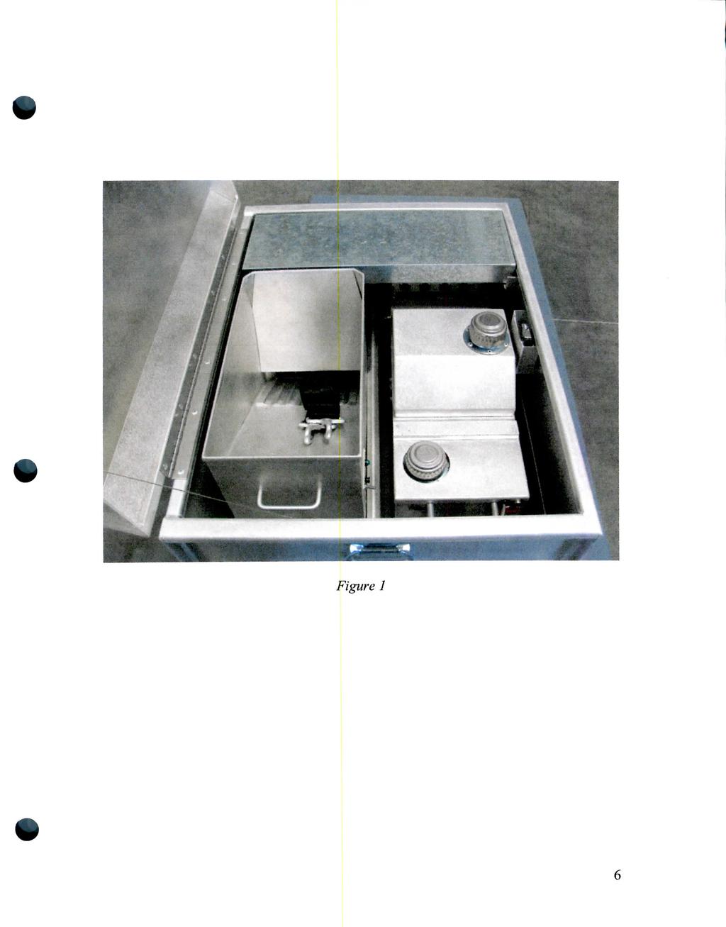
6 Figure 1
![Testing the Dispenser [NOTE: Refer to Figure 2 to identify the location of any component.] Figure 2 Initial Check of the Dispenser 1.](/docs-images/72/66296854/images/7-0.jpg "Remove the hopper from the top of the mainframe to expose the filler caps for both the water and glycol tanks. 2.")
7 Testing the Dispenser [NOTE: Refer to Figure 2 to identify the location of any component.] Figure 2 Initial Check of the Dispenser 1. Remove the hopper from the top of the mainframe to expose the filler caps for both the water and glycol tanks. 2. Lift water tank up from the mainframe (about 2 to 3 inches) and remove water line hose from brass fitting on the bottom of the tank. Set tank aside.
8 3. Unscrew the two wing nuts on the sides of the mainframe to remove mainframe cover. Visually check that all hoses are properly connected, 4. Insert water line through slot in the middle of the cover and then replace cover and retighten wing nuts. [NOTE:JBe sure washers are between the outside edge of the cover and the wing nuts.] 5. Open the water tank and check the strainer in the filler neck. Clean out any debris that may be in it i i 6. Push water line on to the brass fitting on the bottom of the water tank and set the water tank into the four guide holes on the top of the mainframe cover. i 7. Fill water tank with water and replace cap. 8. Open the cap on the glycol tank. Clean out any debris that may be in the strainer. 9. Fill glycol tank with clean ethylene-glycol (aka: antifreeze). Be careful not to overfill tank, hi the event of an oyerfill wipe up all excess glycol being careful not to push any dirt into the tank. 10. Replace the cap on the glycol tank. 11. Install hopper on to the top of the mainframe being careful to align the grooves in the hopper feeder chute with the guides inside the mainframe. [NOTE: When properly positioned the top of the hopper should be parallel with the top of the mainframe.] i 12. Connect the wire lead from the hopper to the "two prong" male plug on the back of the mainframe.! 13. Connect a 24-28vdc power source to the wire coming out of the back of the mainframe. [NOTE: The PSDS power supply can simply be plugged into the plug on the rear of the mainframe.] i 14. Turn on the motor switch (green LED should light) on the mainframe and observe the direction of rotation of the majnual assist wheel on the side of the mainframe. Rotation should be in the direction of the arrow on the wheel. If it is not the lines from the power source need to be: reversed. j 15. Turn on the hopper control panel Switch (the LED indicator should light) and observe that the shuffle plate in the hopper moves back and forth. i 16. Turn off the hopper control switch.
9 17. Move the speed control switch on the main electrical panel into its opposite position and observe a change in the speed of the slipper blocks. 18. Familiarize yourself with the next section of this manual, Priming and Adjusting the Manifold. 19. Turn on the glycol pump control switch on the side of the mainframe. The amber LED should illuminate and you should be able to hear the pump running. 20. Prime the manifold per the instructions in the Priming and Adjusting the Manifold section of the manual. 21. Turn off the glycol pump switch. 22. Depress the emergency water switch button. The red LED should illuminate and you should hear the pump run. Hold the switch button in until you see water coming from the four holes in the manifold. [NOTE: There is no need to prime the water pump.] 23. Release the emergency water switch button. 24. Disconnect the 24-28vdc power source from the dispenser. 9

10 Primins and Adjusting the Manifold Needle Valve Adjustment Manifold This manifold is similar to the manifolds used in older PSD machines. However, its advanced design allows for ease of both priming and adjusting the flow of glycol per the following directions. Lubricate all four plungers with a water proof lubricant where the plunger depresses into the manifold before use. Connect the PSD to a power source and turn on the glycol pump (NOTE: The motor must be in the on position for the glycol pump to work.) Open the bleeder screw (about one turn) located in the brass plug on the side of the manifold using a Phillips screw driver. When glycol starts to escape from the bleeder screw in a steady stream the manifold is primed and the screw should be retightened. (Note: See figure 3 - bleeder screw can be seen protruding from the brass fitting on the left.) Figure 3 10
11 The flow of glycol is adjusted as follows (the procedure must be followed for each of the four needles): Loosen the locking nut all the way. Turn the needle valve in a clockwise direction until it bottoms out. Turn the needle valve no more than ONE QUARTER TURN in a counterclockwise direction. There are orientation marks on both the manifold and the needle valve. The needle valve orientation mark should be located between the two marks on the manifold when properly adjusted (see Figure 4). Figure 4 Hold the needle valve to be sure it does not move while tightening down the locking nut securely. While holding out the manual assist wheel depress the plunger on the manifold for each needle to observe that the flow from each needle is the same. (Proper priming of a sphere requires about.75 cc of glycol.) 11
12 Bench Testing the Dispenser [NOTE: This test should not be done until having first performed the "Initial Check of the Dispenser " as described above. Before beginning this test make sure the machine is located in an area that is well vented. It is strongly recommended that this operation be performed outside any building.] 1. Carefully secure the PSD on a bench with the short chute extending over the edge. [NOTE: The machine must be secured to the bench in order to be certain that it does not tip forward and fall when you start testing.] 2. Place a metal container below the short chute to catch balls. [NOTE: Container should be tall enough so that the balls will not bounce out when dropped into it.] 3. Check the glycol and water tanks to make sure there is glycol and water in the respective tanks and that the glycol pump is primed. 4. Check that the hopper is securely mounted on the mainframe and that the electrical connection is properly secured. 5. Verify that the hopper control handles are in the down position to prevent any spheres from leaving the hopper. 6. Place some live aerial ignition spheres into the hopper and observe that the four chutes leading from the hopper fill with spheres. 7. Connect a vdc power source to the leads coming out of the back of the mainframe. 8. Turn on the motor switch on the mainframe electrical control box and observe the direction of rotation of the manual assist wheel. If the wheel is not rotating in the direction of the arrow shut off the motor and reverse the leads from the vdc power source from the way they are connected. Re-start the motor and verify that the manual assist wheel is turning in the direction of the arrow. 9. Depress the emergency water switch to make certain that the water pump is primed and water will be ejected from the four ports on the manifold. 10. Turn on the hopper control switch to activate the agitator in the hopper. 11. Turn on the pump switch located on the main electrical control box. 12. Raise the inside handle of the hopper control handle to open the two inside chutes and allow two or three spheres from each chute to drop into the container. 12
13 13. Close the hopper control handle and observe the balls in the container to see if they ignite. [NOTE: Should theyifail to ignite refer to the troubleshooting section of this manual.] i 14. Sphere fires inside of the container can be extinguished with a light spray of water. Make sure there is not an excessive amount of water in the bottom of the container before proceeding to the next step. 15. Check to be sure there are enouglj spheres in the hopper to fill the four chutes. Raise both the small and large hopper control chute handles and allow several spheres to drop from each chute. I 16. Close the hopper control handles and observe the spheres in the container. If spheres do not ignite refer to the trouble shooting section of this manual. 17. Extinguish any burning spheres with a light spray of water. 18. Turn off the pump and motor switches. Disconnect the 24-28vdc power source from the dispenser. ' 19. Remove any spheres remaining in the hopper. [NOTE: Be certain that the hopper chutes are all empty when you are done.] 20. Your dispenser is now ready for use. If it not going to be used for a significant amount of time after testing it is recommended that both the water and glycol tanks be drained. To aid in draining the glycol there is a drain valve installed at the bottom of the glycol tank. The water tank can be drained by lifting it from the PSD and removing the water hose or by simply turning the tank over with the cap removed. j 13
14 Using the MARK V Plastic Sphere Dispenser [NOTE: The dispenser should be tested as outlined above before being used to perform a burn.] 1. Make sure that the glycol and water tanks are full, the glycol pump is primed and the water pump is operational. 2. If not already attached to the dispenser attach the harness to the two "D" rings on the front of the machine (see Step 7 in the section entitled "Removal of Dispenser from Its Transit Case"). 3. Set the assembled dispenser inside the helicopter per instructions specific to the make and model being used. If you choose to use the stabilization tray set it in the helicopter first and then place the MARK V into it. 4. Run the harness strap under the helicopter and back in through the opposite side. 5. Attach the end of the harness strap to the buckle hanging from the back of the dispenser and loosely tighten it. 6. Carefully move the dispenser toward the outside of the helicopter until the short drop chute extends over the outside edge and clears any obstruction. Be sure to keep a firm hold on the handle at the back of the dispenser as the dispenser may tip forward. 7. Tighten the harness to hold the dispenser in place. 8. Carefully release your grip on the rear handle making sure the dispenser does not begin to shift. 9. Install the long chute over the short chute. Be sure to slide the long chute all the way up such that the cutouts pass the bolts which extend from each side of the long chute. Tighten the knurled nut on each side to hold it in place (Figures 5a/b). Figure 5a 14
15 Figure 5b 10. Connect the power cord to the plug on the back of the PSD and then connect the other end to the power outlet in the helicopter. 11. Once power is connected to the dispenser turn on the motor switch on the main control panel and verify the direction of rotation on the manual assist wheel is correct (in the direction of the arrow). 12. Be certain that the control handles on the hopper chute are in the down position to prevent balls from falling and then load the hopper with spheres. 13. When you are ready to begin dropping spheres, turn on the drive motor switch on the main control panel and select the speed you want the dispenser to run at (high or low) using the speed control switch. 14. Turn on the glycol pump switch and the hopper switch then lift the handles on the hopper chute to allow the balls to begin dropping. [NOTE: Lifting only the small inside handle will activate the middle two chutes, lifting both the small and large handle will activate all four chutes.] 15. When you wish to stop dropping spheres lower the chute handles to prevent balls from exiting the chute and then observe the drop chute to make certain no other primed spheres are dropping out. (CAUTION: Once the handles are lowered any spheres currently in the slipper block assembly must be allowed to exit from the dispenser as they will have been injected with glycol and therefore will ignite. This could involve about seven spheres depending on how full the hopper was.) 16. Once spheres are all cleared from the machine turn off the hopper motor switch, the glycol pump switch and the drive motor switch. 15
16 Storms the Dispenser 1. Carefully remove the dispenser from the helicopter and place it on a solid surface. 2. Empty any spheres that may be remaining in the hopper and inspect the four chutes to be certain no spheres are left in them. 3. Remove the hopper from the mainframe section of the dispenser. 4. Drain the water tank by removing the cap and then lifting it from the PSD and turning it over. 5. Drain the glycol by positioning the machine so that the drain valve located at the bottom of the glycol tank is accessible. Open the valve and allow the glycol to flow out into a container. 6. Place the stabilization tray into the transit case so that it will sit under the mainframe. 7. Place the mainframe and hopper in there respective places in the transit container. (NOTE: When properly placed in the container the tops of both the mainframe and hopper should be parallel to the upper edge of the case.) 8. Place the drop chute extension in the case making certain it is properly placed in the designated spot. 9. Close the transit case lid and make sure it latches. [NOTE: If the lid does not drop down easily and latch the machine is not properly positioned in the case.] 16
17 TROUBLESHOOTING THE DISPENSER Hopper Motor Fails to Run Make sure that the hopper electrical control wire is plugged into and secured in the mainframe. Verify that the mainframe is connected to a power source. Depress the circuit breaker on the hopper control panel to be sure it is not tripped. Mainframe Motor Fails to Run Make sure the mainframe is connected to a power source. Depress the 2 amp circuit breaker for the motor located on the main control panel next to the drive motor switch to be certain it is not tripped. Depress the 5 amp circuit breaker on the main control panel to be sure it is not tripped. Glycol is Not Pumping If pump can be heard running make sure there is glycol in the tank. If pump fails to operate make certain that mainframe is connected to a power source. Depress the 2 amp circuit breaker on the main control panel next to the glycol pump switch to be sure it is not tripped. Depress the 5 amp circuit breaker on the main control panel to be sure it is not tripped. Water is Not Pumping (NOTE: The water pump is designed to work whenever there is power to the dispenser regardless of what other components are or are not operating. Do not use the dispenser if the water pump is not operational!) If pump fails to operate make certain that mainframe is connected to a power source. Depress the 2 amp circuit breaker on the main control panel next to the red water pump button to be sure it is not tripped. Spheres Fail to Ignite (NOTE: For optimum ignition the spheres should be injected with about.75cc of glycol.) Check to see that the spheres have been punctured by the needles. If they have then: Check the glycol tank to be sure there is sufficient glycol in it. Verify that the glycol pump is functioning and that the manifold has been primed. Lubricate each of the four plungers on the manifold and depress them to be sure they are working properly. Check the needle valve adjustment on the manifold (see Figure 3) : o Rotate each of the needle valve locking nuts in a counterclockwise direction until they stop. 17
18 o Turn each of the needle valves in a clockwise direction until they seat at the bottom of the manifold. (NOTE: The mark on the top of the needle valve should be aligned with the mark on the outside edge of the manifold block.) o Turn the needle valve in a counter clockwise direction keeping the mark on the top of the valve between the two marks on the manifold. o Hold the needle valve in position and tighten the locking nut by turning it in a clockwise direction until it stops. o Repeat this procedure for each of the four needle valves. o Hold the manual assist wheel out to stop the movement of the slipper blocks and depress the plunger under each needle to see that the glycol flow is steady and even. (Proper priming of spheres requires the needle to inject about.75 cc's of glycol into each sphere.) If the dispenser will not operate correctly after performing the appropriate steps in the trouble shooting section contact Aerostat, Inc. ( ). 18
19 APPENDIX 1 Dispenser Specifications Dispenser weight fully assembled less glycol and water Power source 651bs 24-28VDC Dimensions folly assembled Hopper capacity (approx.) Glycol tank capacity Emergency water tank capacity Sphere Diameter length width height inches inches inches 450 spheres 2.4 gal..8 gal inches Sphere shell material High Impact Polystyrene 19
20 APPENDIX 2 Repairs, Updates and Parts for the MARK V dispenser Repairs/Updates to your MARK V can be made by contacting: Aerostat, Inc Airport Blvd. Leesburg, FL Telephone: Fax: custonierservice@aerostatinc.com Parts for your MARK V can also be obtained by contacting Aerostat, Inc. 20
21 APPENDIX 3 User Maintenance of the MARK V Machine Lubrication The most important thing the user can do to assure trouble free operation of the MARK V is to make sure it is kept well lubricated, A non-drying, oily film lubricant such as LPS 2 in aerosol form along with an extension tube that can be inserted into the nozzle is ideal for this. [NOTE: Lubricants such as WD 40 are not recommended!] Liberally apply the lubricant to the slipper block assembly then use the manual assist wheel to move the blocks several tunes to spread the lubricant around evenly.» Using an extension tube on the lubricant can spray each plunger ha the manifold block close to where the plunger < snters the block. Then depress each plunger several tunes to spread the lubricant * Insert the extension tube behind the manual assist wheel into the chain drive cover and spray. Turn the manual assist wheel about a half turn and spray again. This will get lubricant on to the drive chain and drive gears. Keep hi mind that a machine can never be over lubricated providing the right lubricant is used. Pump Maintenance The MARK V contains two identical _ pumps, one for pumping the glycol and the other for pumping water. However, should a pump need to be removed the following information should prove useful to the user: Remove the top of the mainframe and locate the pump housing (Figure A) Unplug the two electrical connections on the front of the housing (Figure A). The entire housing is held hi pi lace by two 7/16 inch head bolts located on the outside of the mainframe, Remove those two bolts and lift the pump housing straight up. [Note: Be careful that the flexible hoses do not snag on anything as you lift up the housing.] 21
. The two pumps will now be easily accessible (Figure B).")
22 , Figure A Lay the pump housing on its back and remove the two bolts holding the cover plate and electric brackets (7/16 inch heads). The two pumps will now be easily accessible (Figure B). Figure B 22

23 For reference purposes the glycol pump abuts the side of the pump housing. Either pump can now be lifted out of the housing. After lifting the pump carefully unplug the electrical connections from the top of the pump. [NOTE: The pumps are marked with a + and - sign by the electric contacts. When reconnecting a pump the red wire goes to the + and the black to the -. When the pump is removed from the housing you will see a cavity in the back of the housing which is critical in repositioning the pump securely. When the pump is placed back in the housing the pump head most be positioned such that the flat side of the head sits against the bottom edge of the cavity (see Figure C). Figure C Cleaning the MARK V To clean the MARK V it is recommended that the user purchase a bottle of white vinegar and a bottle of 3% hydrogen peroxide. Prepare a mixture containing: S 1 part water S 2 parts white vinegar S 1 part 3% hydrogen peroxide In a well ventilated area using rubber gloves and goggles apply the solution to the machine (i.e., use a spray bottle, a brush, cloth, etc.). 23
24 Work the solution into heavily soiled spots with a brush and then let it stand for no more than 15 minutes [Note: If left on more than 15 minutes the solution may begin to corrode some metal parts.] Spray the machine with a water hose to remove all of the solution. Once it is completely rinsed [Note: Don't forget the rinse the bottom of the machine.] move it to a dry location and allow it to air dry. SAFETY NOTE: Do not store the cleaning solution near aerial ignition spheres as contact between the two may result in ignition. 24
DESIGNED BY EXPERIENCE PLASTIC SPHERE DISPENSER USER MANUAL. Manufactured by PSDS, Inc. for sole distribution by:
 DESIGNED BY EXPERIENCE PLASTIC SPHERE DISPENSER USER MANUAL Manufactured by PSDS, Inc. for sole distribution by: AEROSTAT, INC. 8830 AIRPORT BLVD LEESBURG, FL 34788 WEBSITE: AEROSTATINC.COM TEL: 352 787-1348
CLEAN ROOM DEVICES, LLC "WHERE TUBING AND FITTINGS COME TOGETHER"
 CLEAN ROOM DEVICES, LLC "WHERE TUBING AND FITTINGS COME TOGETHER" CRD600AF Automatic Fitting Inserter With Auto Feed OPERATIONS MANUAL (Shown with optional alcohol dispenser) 1 VERSION 1.1 LAST EDITED
CLEAN ROOM DEVICES, LLC "WHERE TUBING AND FITTINGS COME TOGETHER"
 CLEAN ROOM DEVICES, LLC "WHERE TUBING AND FITTINGS COME TOGETHER" CRD600 Automatic Fitting Inserter OPERATIONS MANUAL VERSION 2.1 LAST EDITED 7.25.14 DOCUMENT NUMBER 001 cleanroomdevices.com 1 Table of
OWNER'S MANUAL WARNING DANGER. Propane cylinders sold separately. The propane cylinder must be disconnected when this firebowl is not use.
 OWNER'S MANUAL READ BEFORE USE! Model No.: BH5003-3 Style No.: 66646 For Outdoor Use Only! Use Propane Gas Only! Propane cylinders sold separately. USE PROPANE GAS ONLY! -Do not store or use gasoline or
User Manual GRX- 950 and GRX- 950 Li
 User Manual GRX- 950 and GRX- 950 Li Page 1 of 17 TABLE OF CONTENTS INTRODUCTION 3 BASIC SET- UP 4 TURNING ON YOUR GRX- 950 7 PRECAUTIONS 8 FREE WHEEL MODE 9 GENERAL BATTERY CARE 10 BATTERY INFORMATION
CRD610 Automatic Fitting Inserter
 CRD610 Automatic Fitting Inserter OPERATIONS MANUAL VERSION 1.2 LAST EDITED 12.12.2018 cleanroomdevices.com 1 Table of Contents Title Page. 1 Table of Contents...2 1.0 General Product & Safety Information....3
Backpack Sprayer. Use and Care Manual
 Backpack Sprayer Use and Care Manual BACKPACK SPRAYER CAUTION: Read and follow all instructions Do Not Return This Backpack To The Store For Help, Information or Parts, Call : 1-800-311-9903 The Fountainhead
PowerFlo 20 Parts List/Assembly Instructions/Users Guide ***PLEASE READ ALL INSTRUCTIONS CAREFULLY AND THOROUGHLY***
 PowerFlo 20 Parts List/Assembly Instructions/Users Guide ***PLEASE READ ALL INSTRUCTIONS CAREFULLY AND THOROUGHLY*** Owners Manual (Please check to make sure to locate all parts before assembly.) 11/12/2008
3 Scotch-Weld. User s Manual. Polyurethane Reactive Adhesive Applicator. Use only with 3M Scotch-Weld Polyurethane Reactive Adhesives
 3 Scotch-Weld Polyurethane Reactive Adhesive Applicator User s Manual 120V. USA 100V. JAPAN 120V. USA REFURB Use only with 3M Scotch-Weld Polyurethane Reactive Adhesives Please read all instructions before
Thermo-Bob 3 Installation on a 2015-and-newer Versys 650
 Thermo-Bob 3 Installation on a 2015-and-newer Versys 650 Thank you for purchasing the Thermo-Bob 3 radiator bypass system for the Kawasaki Versys 650. Proper installation is critical: if you are not familiar
RED DRAGON OPERATIONS MANUAL 2018 VERSION G
 RED DRAGON OPERATIONS MANUAL 2018 VERSION G RED DRAGON OPERATIONS MANUAL Version G Issue Date: January 2018 PLEASE READ BEFORE USING. This manual is applicable to the following models: DE002000 (#005851)
Service Manual Air Plus Second Stage
 Service Manual Air Plus Second Stage Includes XS Series Second Stage Copyright 2002, Cressi-sub Revised 3/2002 2 Air Plus Second Stage Service Manual Contents BEFORE STARTING... 3 DISASSEMBLY... 3 PARTS
The Chameleon Trac II Patent Pending M-Series User s Manual
 The Chameleon Trac II Patent Pending M-Series User s Manual YOU MAY ALSO VIEW OUR GENERAL OPERATION VIDEO ONLINE AT: www.marionbrush.com Please read entire manual prior to using this system. Page 1 The
Mitsubishi Lancer Oil Change (2.0L I4 DOHC)
") 2002-2007 Mitsubishi Lancer Oil Change (2.0L I4 DOHC) Change the oil in your '02-'07 Mitsubishi Lancer, with 2.0L I4 DOHC engine, to improve engine performance and longevity. Written By: Phillip Takahashi
2002-2007 Mitsubishi Lancer Oil Change (2.0L I4 DOHC) Change the oil in your '02-'07 Mitsubishi Lancer, with 2.0L I4 DOHC engine, to improve engine performance and longevity. Written By: Phillip Takahashi
Installation, Operation & Maintenance Manual for Flo-Max II Coupler Model FM126
 Installation, Operation & Maintenance Manual for Flo-Max II Coupler Model FM126 December 2015 Form FVC 073 - Rev 09 IMPORTANT: KEEP THIS DOCUMENT WITH THE PRODUCT UNTIL IT REACHES THE END USER. 1. Contact
Perfmaster Air V3. Serial Number. Date
 Perfmaster Air V3 12-2015 Serial Number Date TABLE OF CONTENTS SPECIFICATIONS.3 SAFETY PROCEDURES/CARE & MAINTENANCE..4 COMPONENT IDENTIFICATION 5 DELIVERY TRAY ASSEMBLY.6 PAPER STOP ASSEMBLIES..7 MACHINE
CRD600 Automatic Fitting Inserter
 CRD600 Automatic Fitting Inserter OPERATIONS MANUAL VERSION 2.3 LAST EDITED 12.07.2018 cleanroomdevices.com 1 Table of Contents Title Page.. 1 Table of Contents. 2 1.0 General Product & Safety Information...3
Installation, Operation & Maintenance Manual for Flo-Max II Coupler Model FM126
 IMPORTANT: The Flo-Max II coupler is designed to disconnect the nurse tank hose from a tool bar before the straight pull force on the hose exceeds 450 pounds. Upon disconnect, swing checks in both halves
4000 SYSTEM OPERATING MANUAL
 4000 SYSTEM OPERATING MANUAL REV 1.4 COPYRIGHT 1996 Xenotech, Inc. PAGE 1 INSTRUCTIONS FOR REMOVING AND INSTALLING A TYPE XT XENON BULB IN A BL4000 FIXTURE NOTE FAMILIARIZE YOURSELF WITH THE LOCATION AND
STEALTH BIG AIR KIT - Yamaha Roadliner/Stratoliner and Raider
 Page: 1 If you question your abilities it may be best for an experienced service technician perform this installation. A Yamaha Service Manual would be helpful to have on hand for reference. Revision:
OWNER S MANUAL. Model: FS-ATV-15 ( ) (15 Gallon Lawn & Garden/ATV Sprayer) Technical Specifications. Assembly Instructions. General Information
 (15 Gallon Lawn & Garden/ATV Sprayer) Technical Specifications. Assembly Instructions. General Information") OWNER S MANUAL Model: FS-ATV-15 (5301169) (15 Gallon Lawn & Garden/ATV Sprayer) Technical Specifications 15 Gal. Corrosion-Resistant Polyethylene Tank 12 Volt Diaphragm Pump, 1.8 g.p.m. 60 psi Spot Sprayer
OWNER S MANUAL Model: FS-ATV-15 (5301169) (15 Gallon Lawn & Garden/ATV Sprayer) Technical Specifications 15 Gal. Corrosion-Resistant Polyethylene Tank 12 Volt Diaphragm Pump, 1.8 g.p.m. 60 psi Spot Sprayer
M-3025CB-AV Fuel Pump
 SAVE THESE INSTRUCTIONS M-3025CB-AV Fuel Pump Owner s Manual TABLE OF CONTENTS General Information... 2 Safety Instructions... 2 Installation... 3 Operation... 4 Maintenance... 4 Repair... 5 Troubleshooting...
HYDRAULIC TROLLEY JACK K Distributed by Kincrome Tools and Equipment:
 HYDRAULIC TROLLEY JACK K12076 Distributed by Kincrome Tools and Equipment: www.kincrome.com.au Owner s Assembly and Operating Manual SPECIFICATIONS... 2 IMPORTANT SAFETY INFORMATION... 3 UNPACKING AND
BOLT-ON AND WELD-ON FLUSH FLOOR SLIDEOUT SYSTEMS OPERATION AND SERVICE MANUAL
 BOLT-ON AND WELD-ON FLUSH FLOOR SLIDEOUT SYSTEMS OPERATION AND SERVICE MANUAL TABLE OF CONTENTS SYSTEM...... Warning........ Description...... Prior to Operation OPERATION... Main Components... Mechanical...
6-12 WIDESPREAD 6-12 W. Cleopatra Series INSTRUCTION GUIDE SAVE THIS INSTRUCTION GUIDE
 INSTRUCTION GUIDE STEP-BY-STEP ILLUSTRATED INSTALLATION INSTRUCTIONS TROUBLE SHOOTING & REPAIR TIPS 20 YEAR LIMITED WARRANTY PROPER FINISH CARE Read these instructions carefully before installing your
COMPONENT WORK SAMPLE 8 Simulated Assembly MAINTENANCE MANUAL. From 1974 to March 15, 2003
 COMPONENT WORK SAMPLE 8 Simulated Assembly MAINTENANCE MANUAL From 1974 to March 15, 2003 Copyright 2008 VALPAR International Corporation P.O. Box 5767 Tucson, Arizona 85703-5767 All rights reserved. No
OWNER S MANUAL EVOLUTION 3500, 4500, 5500, & 8500 SERIES PUMPS
 OWNER S MANUAL EVOLUTION 3500, 4500, 5500, & 8500 SERIES PUMPS IMPORTANT SAFETY INSTRUCTIONS When installing and using this electrical equipment, basic safety precautions should always be followed, including
18V Cordless Chain Saw INSTRUCTION MANUAL
 18V Cordless Chain Saw INSTRUCTION MANUAL WARNING: Read and understand RULES FOR SAFE OPERATION and instructions carefully before operating. Failure to follow the safety rules and other basic safety precautions
Meinzer II TM. Testing Sieve Shaker
 Meinzer II TM Testing Sieve Shaker Operation & Set-up Manual Model: 18480100 CSC Scientific, Inc. 2799-C Merrilee Drive Fairfax, VA 22031 USA Telephone: (703) 876-4030 (800) 621-4778 Fax: 703-280-5142
Honda Civic Oil Change
 1988-1991 Honda Civic Oil Change Change the oil in your '88-'91 Honda Civic to improve engine performance and longevity. Written By: Phillip Takahashi ifixit CC BY-NC-SA www.ifixit.com Page 1 of 13 INTRODUCTION
Oreck Magnesium Series Service Manual. The Oreck Manufacturing Company
 Oreck Magnesium Series Service Manual The Oreck Manufacturing Company 08/2012 10/2011 The Oreck Manufacturing Company Contents Covering all Magnesium Upright Models Including: LW100, LW125, LW1000, AND
PowerFlo Parts List/Assembly Instructions/Users Guide ***PLEASE READ ALL INSTRUCTIONS CAREFULLY AND THOROUGHLY***
 PowerFlo Parts List/Assembly Instructions/Users Guide ***PLEASE READ ALL INSTRUCTIONS CAREFULLY AND THOROUGHLY*** Owners Manual (Please check to make sure to locate all parts before assembly.) 11/12/2008
Arch HTH Water Chemicals Commercial Equipment Trouble Shooting Guide
 Arch HTH Water Chemicals Commercial Equipment Trouble Shooting Guide 8/28/00 TROUBLESHOOTER S GUIDE PROBLEM CAUSE SOLUTION Insufficient water flow to chlorinator Check water flow through Flow Controller
WCI-20 Power-Pak Coldwork Hydraulic Power Supply Rev B
 WCI-20 Power-Pak Coldwork Hydraulic Power Supply Rev B OM-PS-9303-2 Seattle, Washington WCI-20 Power Pak Manual Table of Contents Section 1 Introduction 1.1 Introduction... 1 1.2 Safety Precautions...
MOTORVAC TECHNOLOGIES INC. TRANSTECH-1000 Transmission Service System
 MOTORVAC TECHNOLOGIES INC. TRANSTECH-1000 Transmission Service System OPERATOR MANUAL UNIT MODEL NUMBER 500-1101 TRANSTECH 1000 OPERATOR MANUAL - 100-1101 Rev. A, 2006 Table of Contents Introduction...3
Model Model (230V) High Speed Letter Opener
 High Speed Letter Opener") R Model 6200 Model 62002 (230V) High Speed Letter Opener Specifications Functional Speed..................................Up to 7,500 per Hour Maximum Envelope Thickness............................./4
R Model 6200 Model 62002 (230V) High Speed Letter Opener Specifications Functional Speed..................................Up to 7,500 per Hour Maximum Envelope Thickness............................./4
BL7000 SYSTEM OPERATING MANUAL
 BL7000 SYSTEM OPERATING MANUAL REV 2.0 208 / 230V COPYRIGHT 1995 Xenotech, Inc. PAGE 1 POWER INPUT CONNECTOR WIRING INSTRUCTIONS THE INPUT POWER REQUIREMENTS FOR A 7 KW POWER SUPPLY ARE AS FOLLOWS. VOLTAGE
Alliance Towel Dispensing System. Operation Manual
 Alliance Towel Dispensing System Operation Manual Alliance Towel Dispensing System Table of Contents Safety Information... page 2 Mounting Instructions... page 3 Towel Loading Instructions... page 7 Settings...
INSTALLATION MANUAL SPECTRUM BRAKE CONTROL
 INSTALLATION MANUAL 51170 SPECTRUM BRAKE CONTROL TABLE OF CONTENTS Controls & Components Tools List Before You Begin Wiring Wiring Diagram Mounting the LED Display Rotary Knob Wiring the Plug Connector
IMPORTANT! DO NOT THROW AWAY THE SHIPPING CARTON AND PACKING MATERIAL
 Operator s Manual IMPORTANT! DO NOT THROW AWAY THE SHIPPING CARTON AND PACKING MATERIAL ii Table of Contents Operator Safety... 1 Introduction... 2 Unpacking and Setup... 3 Unpacking... 3 Setup... 4 ROCKET
MODEL CJ-95 CoilJet Portable HVAC Coil Cleaning System
 MODEL CJ-95 CoilJet Portable HVAC Coil Cleaning System OPERATING AND MAINTENANCE INSTRUCTIONS CJ-95 Manual 2009 All Rights Reserved 07/2009 Table of Contents Warranty... 1 Important Safety Instructions...
255 Liter/Hr, In Tank Fuel Pump For Chrysler Front Wheel Drive Vehicles Catalog # INSTALLATION INSTRUCTIONS
 255 Liter/Hr, In Tank Fuel Pump For 1984-1990 Chrysler Front Wheel Drive Vehicles Catalog # 17934 INSTALLATION INSTRUCTIONS PLEASE study these instructions carefully before installing your new In-Tank
FPU SYSTEMS OPERATION MANUAL (INCLUDING REPAIR PARTS & SPECIAL TOOL LIST) BOH CONTAINERIZED LATRINES BOH FPU Field Pack-up Units
 BOH CONTAINERIZED LATRINES BOH FPU Field Pack-up Units") FPU SYSTEMS OPERATION MANUAL (INCLUDING REPAIR PARTS & SPECIAL TOOL LIST) BOH CONTAINERIZED LATRINES BOH FPU Field Pack-up Units CHAPTER 4 OPERATOR MAINTENANCE INSTRUCTIONS 2016 BOH Environmental LLC This
FPU SYSTEMS OPERATION MANUAL (INCLUDING REPAIR PARTS & SPECIAL TOOL LIST) BOH CONTAINERIZED LATRINES BOH FPU Field Pack-up Units CHAPTER 4 OPERATOR MAINTENANCE INSTRUCTIONS 2016 BOH Environmental LLC This
READ AND FOLLOW ALL SAFETY INSTRUCTIONS SAVE THESE INSTRUCTIONS
 7.5 Swift Lock Ready Shape Tree (Patent Pending) Instructions IMPORTANT SAFETY INSTRUCTIONS When using electrical products, basic precautions should always be followed including the following: READ AND
Service Manual Air Tech Second Stage
 Service Manual Air Tech Second Stage Copyright 2002, Cressi-sub Revised 3/2002 2 Air Tech Second Stage Service Manual Contents BEFORE STARTING... 3 DISASSEMBLY... 3 PARTS CLEANING AND LUBRICATION... 9
RENA AF371Feeder Operating Manual. Feeder. Operating Manual. Manual Part #: M AF371 Operations Rev
 Manual Part #: M-3022 Feeder AF371 Operations Rev. 3-16-04 1 RENA AF371 Feeder YOUR RENA AF371 IS DISTRIBUTED BY RENA SYSTEMS INC. SERVICE AND SUPPORT FOR THIS PRODUCT IS PROVIDED BY YOUR RENA DEALER.
Description of the Power Nozzle Accessory Kit 4
 Contents IMPORTANT SAFETY INSTRUCTIONS 2 Polarization Instructions 3 Description of the Power Nozzle Accessory Kit 4 Operating the Power Nozzle & Accessories 5 Inserting the hose Turning on the power nozzle
Maintenance Information
 16573370 Edition 2 February 2014 Air Grinder 99V Series Maintenance Information Save These Instructions Product Safety Information WARNING Failure to observe the following warnings, and to avoid these
Auto Sentry-eXP Maintenance. Revised 12/21/07
 Auto Sentry-eXP Maintenance Revised 12/21/07 Maintenance Procedures for Auto Sentry exp Bill Dispenser Credit Card Reader Bill Acceptor Bill Dispenser Maintenance Bill Dispenser Problem / Cause Bill Dispenser
This is the Unpacking Guide for the Optibike Pioneer Allroad electric bicycle. The Guide provides information required to remove the Allroad from the
 This is the Unpacking Guide for the Optibike Pioneer Allroad electric bicycle. The Guide provides information required to remove the Allroad from the box and assemble it. If you have not assembled a bicycle
Backpack Sprayer. CAUTION: Read and follow all instructions. Use and Care Manual NO LEAK BACKPACK SPRAYER
 Backpack Sprayer Use and Care Manual NO LEAK BACKPACK SPRAYER CAUTION: Read and follow all instructions Do Not Return This Sprayer To The Store For Help, Information or Parts, Call : 1-800-311-9903 The
Z-Truck (Vertical Moving) Z-truck Flag. Y-Truck (Horizontal Moving) FIGURE 1: VIEW OF THE Z-TRUCK. Flexshaft Assembly
 Z-truck Flag. Y-Truck (Horizontal Moving) FIGURE 1: VIEW OF THE Z-TRUCK. Flexshaft Assembly") Checking and Replacing the AC Motor To remove and replace the AC Motor you will need the following tools: #2 Phillips screwdriver (magnetic tip preferred) Removing the AC Motor 1. Ready the machine by
Checking and Replacing the AC Motor To remove and replace the AC Motor you will need the following tools: #2 Phillips screwdriver (magnetic tip preferred) Removing the AC Motor 1. Ready the machine by
FREE $15 Gift Card for every $100 spent on Ship To Home orders. Find Out How
 1 of 29 10/12/2011 5:05 PM FREE $15 Gift Card for every $100 spent on Ship To Home orders. Find Out How Ford Ranger/Explorer/Mountaineer 1991-1999 Intake Manifold REMOVAL & INSTALLATION Print The engines
Introduction. Installation. Maintenance. Bill of Materials
 Table of Contents Introduction Specitications... 3 Operation... 4 Installation New Installations... 6 Retrofit Installations... 6 Flow Control Switch... 7 Dimensions... 8 E-7 Valve... 28 E-7 Valve with
Owner and Operating Manual for
 Owner and Operating Manual for 120VAC Manual Control 12VDC Solar Battery Manual Control 120VAC Remote Control 12VDC Solar Battery Remote Control GEN2 Remote Versions Only Boat Lifts Please read this manual
Cummins 6.7 Litre 2500/3500 Diesel EGR System. Always wear gloves and safety glasses when performing this service
 Cummins 6.7 Litre 2500/3500 Diesel EGR System Always wear gloves and safety glasses when performing this service EGR System Consists of: Cold side EGR valve (after EGR cooler) controls exhaust gases for
PowerFlo 50 Parts List/Assembly Instructions/Users Guide ***PLEASE READ ALL INSTRUCTIONS CAREFULLY AND THOROUGHLY***
 PowerFlo 50 Parts List/Assembly Instructions/Users Guide ***PLEASE READ ALL INSTRUCTIONS CAREFULLY AND THOROUGHLY*** Owners Manual (Please check to make sure to locate all parts before assembly.) 11/12/2008
3 Scotch-Weld. User s Manual. Polyurethane Reactive (PUR) Easy Adhesive Applicator
 Easy Adhesive Applicator") 3 Scotch-Weld Polyurethane Reactive (PUR) Easy Adhesive Applicator 120V. USA 100V. JAPAN 120V. USA REFURB User s Manual Use only with 3M Scotch-Weld Polyurethane Reactive (PUR) Easy Adhesives Please read
3 Scotch-Weld Polyurethane Reactive (PUR) Easy Adhesive Applicator 120V. USA 100V. JAPAN 120V. USA REFURB User s Manual Use only with 3M Scotch-Weld Polyurethane Reactive (PUR) Easy Adhesives Please read
Owner smanual. Banks Ram-Air Intake System Chevrolet 6.6L (LML) Duramax Turbo-Diesel Pickups. with Installation Instructions
 Duramax Turbo-Diesel Pickups. with Installation Instructions") with Installation Instructions Owner smanual Banks Ram-Air Intake System 2013-2014 Chevrolet 6.6L (LML) Duramax Turbo-Diesel Pickups THIS MANUAL IS FOR USE WITH KIT 42230 & 42230-D Gale Banks Engineering
with Installation Instructions Owner smanual Banks Ram-Air Intake System 2013-2014 Chevrolet 6.6L (LML) Duramax Turbo-Diesel Pickups THIS MANUAL IS FOR USE WITH KIT 42230 & 42230-D Gale Banks Engineering
Electric Trolling Motor
 Electric Trolling Motor L Series User s Manual Please read and retain this manual before using product REACH RoHS TABLE OF CONTENTS Contents GENERAL INFORMATION 4 SPECIFICATIONS 4 WIRING AND BATTERY RECOMMENDATIONS
Injector. General Information CAUTION. Use only the specified injector for the engine.
 Page 1 of 32 006-026 Injector General Information CAUTION Use only the specified injector for the engine. All engines use closed nozzle, hole-type injectors. However, the injectors can have different part
Instruction Manual Recharging Aids and Dock
 Instruction Manual Recharging Aids and Dock Charge! We re thrilled to be on your hearing journey. You hold in your hands a guide to using and caring for your rechargeable hearing aid kit Congrats, your
Brushcutters. Bent Shaft Brushcutter. Straight Shaft Brushcutter BCS260 BCB260
 Brushcutters BCB260 Bent Shaft Brushcutter BCS260 Straight Shaft Brushcutter Please read this instruction manual carefully before operating your new Sanli Brushcutter. Congratulations on choosing a Sanli
Centrifuge Operator / Service Manual
 3000 Centrifuge Centrifuge Operator / Service Manual cat.# 26230 & 26231 The Q-sep 3000 centrifuge complies with all requirements of UL standard 3101 20, Can/CSA C22.2 No. 1010.1, and Can/CSA C22.2 No.
MODEL MA4210 Installation and Operation Manual Important:
 MODEL MA4210 Installation and Operation Manual Important: This manual contains specific cautionary statements relative to worker safety. Read this manual thoroughly and follow as directed. It is impossible
TBE-700. Operation, Safety and Maintenance Manual. Stainless Steel Weld Cleaning System. Ensitech Pty Ltd
 Stainless Steel Weld Cleaning System Operation, Safety and Maintenance Manual TBE-700 TBE-700 Instruction Manual Oct 2013 (USA) FOREWORD FOREWORD This manual is a very important tool! Keep it with the
Heavy Duty Engine Cranes
 Heavy Duty Engine Cranes Operating Instructions & Parts Manual Model Number Atd-7484 Atd-7485 (Foldable Legs) Capacity 2 Ton 2 Ton Model Atd-7484 Model Atd-7485 Atd Tools Inc. 160 Enterprise Drive, Wentzville,
OWNER S MANUAL. Model: UTL-60-12V ( ) (60 Gallon Lawn & Garden Utility Sprayer w/5-nozzle Boom)
 (60 Gallon Lawn & Garden Utility Sprayer w/5-nozzle Boom)") OWNER S MANUAL Model: UTL-60-12V (5301347) (60 Gallon Lawn & Garden Utility Sprayer w/5-nozzle Boom) Technical Specifications 60 Gal. Corrosion-Resistant Polyethylene Tank Deluxe Pistol-Grip Handgun w/25
OWNER S MANUAL Model: UTL-60-12V (5301347) (60 Gallon Lawn & Garden Utility Sprayer w/5-nozzle Boom) Technical Specifications 60 Gal. Corrosion-Resistant Polyethylene Tank Deluxe Pistol-Grip Handgun w/25
CALIFORNIA TRIMMER MOWER MAINTENANCE MANUAL
 CALIFORNIA TRIMMER MOWER MAINTENANCE MANUAL 2 Table of Contents Section 1: General Information Page Handle Assembly Instructions 4 Maintenance All Models 6 Oil Change Procedures All Models 9 Height Adjustment
OWNER S MANUAL. Model: UTV-65-BL ( ) (65 Gallon Lawn & Garden UTV Sprayer w/boomless Boom)
 (65 Gallon Lawn & Garden UTV Sprayer w/boomless Boom)") OWNER S MANUAL Model: UTV-65-BL (5302843) (65 Gallon Lawn & Garden UTV Sprayer w/boomless Boom) Technical Specifications 65 Gal. Corrosion-Resistant Polyethylene Tank Deluxe Pistol-Grip Handgun 25 Ft.
OWNER S MANUAL Model: UTV-65-BL (5302843) (65 Gallon Lawn & Garden UTV Sprayer w/boomless Boom) Technical Specifications 65 Gal. Corrosion-Resistant Polyethylene Tank Deluxe Pistol-Grip Handgun 25 Ft.
OWNER S MANUAL. Model: FSUTV-45-12V ( ) (45 Gallon Lawn & Garden UTV Sprayer, Boom Ready) Technical Specifications. Assembly Instructions
 (45 Gallon Lawn & Garden UTV Sprayer, Boom Ready) Technical Specifications. Assembly Instructions") OWNER S MANUAL Model: FSUTV-45-12V (5302903) (45 Gallon Lawn & Garden UTV Sprayer, Boom Ready) Technical Specifications 45 Gal. Corrosion-Resistant Polyethylene Tank Deluxe Pistol-Grip Handgun 25 Ft. Handgun
OWNER S MANUAL Model: FSUTV-45-12V (5302903) (45 Gallon Lawn & Garden UTV Sprayer, Boom Ready) Technical Specifications 45 Gal. Corrosion-Resistant Polyethylene Tank Deluxe Pistol-Grip Handgun 25 Ft. Handgun
GL Ludemann Y-Strainers
 GL Ludemann Y-Strainers Installation, Operation and Maintenance Manual English Issue 1-03/2014 - Page 1/7 GENERAL These instructions are for installing, operation and maintenance of Y-strainers fabricated
AEROMOTIVE Part # & Stealth Fuel Tank Sump INSTALLATION INSTRUCTIONS
 AEROMOTIVE Part # 18651 & 18652 Stealth Fuel Tank Sump INSTALLATION INSTRUCTIONS CAUTION: Installation of this product requires detailed knowledge of automotive systems and repair procedures. We recommend
OXYGEN GENERATING SYSTEMS INTL. Oxygen System Start-up, Overview and Maintenance Guide
 OXYGEN GENERATING SYSTEMS INTL. Oxygen System Start-up, Overview and Maintenance Guide OXYGEN GENERATOR SYSTEM START-UP STEP 1 Walk around the skid and inspect for damage. Then check that all electrical
1600 PSI ELECTRIC PRESSURE WASHER
 MODEL NO.: XE03 SKU: 39-8508-6 1600 PSI ELECTRIC PRESSURE WASHER Owner s Manual QUESTIONS, PROBLEMS, MISSING PARTS? Before returning to your retailer, visit our web site or call our customer service at
Blue Jay Rodless Cylinder BC MS. Track Repair Manual 1996 & 2012 THE EASTMAN EASTMAN. All End Caps Black for Models
 EASTMAN 1996 & 2012 THE EASTMAN Blue Jay Rodless Cylinder BC-40224-MS Track Repair Manual All End Caps Black for 1996-2012 Models IMPORTANT Disconnect this equipment from pneumatic pressure lines before
Written By: David Hodson
 2008-Present Scion xb Oil Change Second generation Scion xb oil change. Written By: David Hodson ifixit CC BY-NC-SA www.ifixit.com Page 1 of 19 INTRODUCTION Change the oil in your 2008 or newer Scion xb
Instruction & Owner s Manual
 Instruction & Owner s Manual Table of Contents Page Installation - Plumbing of Chamber 3 Installation - Electronic Control Box 3-4 Transformer Connection 115VDC or 230VDC 4-5 Instructions for use with
Remove 4 circled pins. Route wiring along dashed line. Remove the 2 9mm nuts and black retaining plate that secure extractor.
 2015 Ford Mustang Turn Signal Hood Kit Parts List: Quantity: Tool List: Bracket & pre-installed lamp 2 Flat head screwdriver Wiring harness 1 Phillips screwdriver PB-3660 Parts Bag 1 Ratchet & Socket set
EGR Adapter Ford 6.7 L
 EGR Adapter Ford 6.7 L Part No. 069-3390 CAUTION: Always wear gloves and safety glasses when performing this service EGR System Consists of: Hot side EGR valve (before EGR cooler) controls exhaust gases
M-1115S Series Fuel Pump
 SAVE THESE INSTRUCTIONS M-1115S Series Fuel Pump Owner s Manual TABLE OF CONTENTS General Information...2 Safety Instructions...2 Installation...3 Operation...4 Maintenance...5 Repair...5 Troubleshooting...9
TBV OPERATION AND MAINTENANCE MANUAL SERIES 1800: FLANGED BALL VALVE. For technical questions, please contact the following:
 TBV OPERATION AND MAINTENANCE MANUAL SERIES 1800: FLANGED BALL VALVE For technical questions, please contact the following: Engineering Department 1537 Grafton Road Millbury, MA 01527 Phone: (508) 887-9400
section-page Table 1. Transfer switching device ratings. Conditional short circuit current
 Operator s Manual 7000 Series ATS Automatic Transfer Switching Equipment D design 30 through 200 amperes TABLE OF CONTENTS section-page INSTALLATION... 1-1 Enclosures and Mounting... 1-1 Power Connections...
w w w. h d o n l i n e s h o p. d e SCREAMIN' EAGLE "HEAVY BREATHER" PERFORMANCE AIR CLEANER KIT GENERAL INSTALLATION -J04480 REV.
 -J080 REV. 2009-05-2 SCREAMIN' EAGLE "HEAVY BREATHER" PERFORMANCE AIR CLEANER KIT GENERAL Kit Numbers 292-08, 29080-09 Models For model fitment information, see the P&A Retail Catalog or the Parts and
SUPER PUMP OUT SYSTEM
 Congratulations on your purchase of the SUPER PUMP OUT SYSTEM. This instruction/parts manual is a guide for operating and servicing your BLUELINE SUPER PUMP OUT SYSTEM. Proper operation and service are
Lumina 28 Traction Drive Model: Battery Burnisher M28036TDQP OPERATION SERVICE PARTS CARE
 Lumina 28 Traction Drive Model: Battery Burnisher M28036TDQP OPERATION SERVICE PARTS CARE Table of Contents IMPORTANT SAFETY INSTRUCTIONS...1 OPERATING INSTRUCTIONS...2 INSPECTION...2 ELECTRICAL...2 BATTERIES...2
HYDRAULIC LEVELING SYSTEMS OPERATIONS MANUAL (For systems with touch pad part number , , , , or no number at all)
") HYDRAULIC LEVELING SYSTEMS OPERATIONS MANUAL (For systems with touch pad part number 500089, 500105, 500210, 500456, 500535 or no number at all) Visit us on the web at www.powergearus.com 82-L0040-01 Rev.
HYDRAULIC LEVELING SYSTEMS OPERATIONS MANUAL (For systems with touch pad part number 500089, 500105, 500210, 500456, 500535 or no number at all) Visit us on the web at www.powergearus.com 82-L0040-01 Rev.
SUREFIRE 512 STOVE SENTRY INSTRUCTION MANUAL
 SUREFIRE 512 STOVE SENTRY INSTRUCTION MANUAL Contents 1. WARNING................................. 1 2. Introduction................................2 3. Inspection.................................2 4. Heating
SSX-300ST SolarMaxx 300 Illuminator
 SSX-300ST SolarMaxx 300 Illuminator Service Manual 6018 Bowdendale Avenue Jacksonville, FL 32216 Customer Service: 904 731 5869 FAX 904 733 0012 Toll Free 800 684 6404 (English) TABLE OF CONTENTS Page
Remove the 3-11mm nuts holding mirror on. Don t drop the nuts!
 2005-2012 Ford Mustang Puddle Lamp Kit Parts List: Quantity: Tool List: LED Lamps 2 Flat head screwdriver Seals 2 Ratchet & Socket set OR Nuts 2 Adjustable Wrench Wiring harness 1 Drill & 11/16 th bit
SLP Camaro ZL1 STAGE 2 (625 HP)
") SLP - 2012 Camaro ZL1 STAGE 2 (625 HP) PART #26001 PACKING LIST Before installation, use this check list to make sure all necessary parts have been included. ITEM QTY CHECK PART NUMBER DESCRIPTION 1. 1
SLP - 2012 Camaro ZL1 STAGE 2 (625 HP) PART #26001 PACKING LIST Before installation, use this check list to make sure all necessary parts have been included. ITEM QTY CHECK PART NUMBER DESCRIPTION 1. 1
2013 IMPCO Technologies, Inc. Page 1 of 20 EPR Repair Kit Instructions (PPI-122, Rev-B)
") EPR Repair Kit Instructions PPI-122 (Rev-B) A. Introduction: This document covers the repair of the Electronic Pressure Regulator (EPR) used on Spectrum III series fuel systems. These instructions will
EPR Repair Kit Instructions PPI-122 (Rev-B) A. Introduction: This document covers the repair of the Electronic Pressure Regulator (EPR) used on Spectrum III series fuel systems. These instructions will
Pro Gun (Model: UCpro and UCPro Plus)
") Undercoating/Rustproofing Pro Gun (Model: UCpro and UCPro Plus) Professional Undercoating and Rustproofing gun designed to apply protective coatings such as waterborne and solvent based under coatings,
Undercoating/Rustproofing Pro Gun (Model: UCpro and UCPro Plus) Professional Undercoating and Rustproofing gun designed to apply protective coatings such as waterborne and solvent based under coatings,
INSTALLATION INSTRUCTIONS
 INSTALLATION INSTRUCTIONS PERFORMANCE AT THE WHEELS KITS W156-6 & W156-7 1965-74 MOPAR B & E BODY Thank you for choosing STAINLESS STEEL BRAKES CORPORATION for your braking needs. Pleases take the time
Air Actuated Hydraulic Bottle Jacks
 Air Actuated Hydraulic Bottle Jacks Operating Instructions & Parts Manual Model Number Atd-7412 Atd-7420 Capacity 12 Ton 20 Ton Atd Tools Inc. 160 Enterprise Drive, Wentzville MO 63385 Printed in China
Relius UV-Cure Adhesive Coating Dispenser Manual
 Relius UV-Cure Adhesive Coating Dispenser Manual User s Guide Electronic pdf files of EFD manuals are also available at www.efd-inc.com/manuals.html A NORDSON COMPANY Introduction You have selected a reliable,
THANK YOU FOR CHOOSING BATHERBOX GETTING STARTED WHAT S IN THE BOX? N. Northview Ave Sioux Falls, SD 57107
 INSTRUCTION MANUAL THANK YOU FOR CHOOSING BATHERBOX You are on your way to creating an unmatched bathing experience both for you and the lucky animal. The BatherBox is designed to save you hours of time
5.5KVA GENERATOR MODEL NO: PG6500DVES OPERATION & MAINTENANCE INSTRUCTIONS PART NO: LS0616
 5.5KVA GENERATOR MODEL NO: PG6500DVES PART NO: 8857810 OPERATION & MAINTENANCE INSTRUCTIONS LS0616 INTRODUCTION Thank you for purchasing this CLARKE 5.5KVA Generator. Before attempting to use this product,
INSTALLATION INSTRUCTIONS
 INSTALLATION INSTRUCTIONS DISC BRAKE CONVERSION KITS A120-4 & A120-5 1964-1/2-66 Ford & Mercury Thank you for choosing STAINLESS STEEL BRAKES CORPORATION for your braking needs. Pleases take the time to
L DODGE CUMMINS BD FLOWMAX LIFT PUMP KIT
 6/15/2016 #1050311D 2010-12 6.7 Dodge Cummins FlowMAX Lift Pump Kit (I-00329) - 1-2010-12 6.7L DODGE CUMMINS BD FLOWMAX LIFT PUMP KIT Installation Instructions P/N # 1050311D PLEASE READ ALL INSTRUCTIONS