Assembly and Operational Instructions Manual
|
|
|
- Drusilla Charles
- 6 years ago
- Views:
Transcription

1 Assembly and Operational Instructions Manual Manual by Morne Nortier Office Taiwan: No.9.39 Lane,Yuag-Chang 2nd Street, Ren-Wu Hsiang, Kaohsiung Hsien, 814, Taiwan, R.O.C. TEL: FAX: Tech support : likai701030@yahoo.com For any further information and updates please visit SM 2009
2 Index: INTRODUCTION... 3 DISCLAIMER...3 WARNING...3 ARF PAINT...4 FINISHING YOUR WHITE MIG29 ARF...4 HANDLING & TRANSPORTING...5 LIVE HINGE TOOL LIST... 6 HEALTH...7 GENERAL ASSEMBLY TECHNIQUES... 7 RADIO EQUIPMENT...8 COMPOSITE PARTS...9 OPTIONAL PARTS...10 CONTROL LINKAGES...11 WINGS...11 STABILIZERS...13 FIN & RUDDER LANDING GEARS & DOORS TAIL PIPE CONVENTIONAL TAILPIPE & VECTOR NOZZLES..20 FUEL CELLS FUEL DIAGRAM 23 TURBINE INSTALLATION AIR SYSTEM AIR DIAGRAM COCKPIT & CANOPY EQUIPMENT INSTALLATION INTO THE MIG29 ARF...28 BEFORE YOU FLY P-2
3 INTRODUCTION Assembly & Operation Manual Thank you for purchasing Skymaster MIG29! We have put a lot of effort and time into this model. We at Skymaster strive to be a market leader in the ARF jet market. We were the first company to produce ARF jets in the world and we would like to continue being amongst the best. Although we have made every effort that this model was fit for shipping, we would like you to inspect the contends and call your nearest dealer immediately if any defects or missing parts are spotted! This manual will allow you to duplicate the factory prototypes. LIABILITY You have acquired a kit, which can be assembled into a fully working R/C model when fitted out with suitable accessories, as described in the instruction manual with the kit. However, as manufacturers, we at Skymaster are not in a position to influence the way you build and operate your model, and we have no control over the methods you use to install, operate and maintain the radio control system components. For this reason we are obliged to deny all liability for loss, damage or costs which are incurred due to the incompetent or incorrect application and operation of our products, or which are connected with such operation in any way. Unless otherwise prescribed by binding law, the obligation of the Skymaster company to pay compensation is excluded, regardless of the legal argument employed. This applies to personal injury, death, damage to buildings, loss of turnover and business, interruption of business or other direct and indirect consequent damages. In all circumstances our total liability is limited to the amount which you actually paid for this model. BY OPERATING THIS MODEL YOU ASSUME FULL RESPONSIBILITY FOR YOUR ACTIONS. It is important to understand that Skymaster, is unable to monitor whether you follow the instructions contained in this instruction manual regarding the construction, operation and maintenance of the aircraft, nor whether you install and use the radio control system correctly. For this reason we at Skymaster are unable to guarantee, or provide, a contractual agreement with any individual or company that the model you have made will function correctly and safely. You, as operator of the model, must rely upon your own expertise and judgement in acquiring and operating this model. WARNING This jet aircraft is a high-end product and can create an enormous risk for both pilot and spectators, if not handled with care, and used according to the instructions. Make sure that you operate your MIG29 according to the AMA rules, or those laws and regulations governing model flying in the country of use. The engine, landing gear, servos, linkages and control surfaces have to be attached properly. Please use only the recommended servos and accessories. Make sure that the Centre of Gravity is located in the recommended place. Use the nose heavy end of the CG range for your first flights. A tail heavy plane can be an enormous danger for you and all spectators. Fix any weights, and heavy items like batteries, very securely into the plane. Make sure that the plane is secured properly when you start the engine. Have a helper hold your plane from the nose before you start the engine. Make sure that all spectators are far behind, or far in front, of the aircraft when running up the engine. Make sure that you range check your R/C system thoroughly before the 1st flight. It is absolutely necessary to range check your complete R/C installation first WITHOUT the engine running. Leave the transmitter antenna retracted, and check the distance you can walk before fail-safe occurs. Then start the engine, run at about half throttle and repeat this range check. Make sure that there is no range reduction before failsafe occurs. If the range with engine running is less then with the engine off, please DON T FLY at that time. Make sure that your wing spar tube is not damaged. Check that the anti-rotation dowels for the wings are not loose. Check that the wing, stab, fin and nose retaining bolts are tight. Please don t ignore our warnings, or those provided by other manufacturers. They refer to things and processes which, if ignored, could result in permanent damage or fatal injury. Secure the plane before starting engine. P-3
4 ARF Paint The color finish on your Skymaster MIG29 model was applied out of the mould. We have used only the highest standard automotive paints to finish your model. Should you damage the finish, Skymaster stock the color paint and hardener required for the repair. A good automotive spray painter should also be able to mix and supply the correct samples for repair. If you have no experience in the use of these paints, it will be best to seek assistance. Do not leave your model unprotected in the sun! always cover your model or park it in the shade. Extreme temperatures will damage the paint! Finishing Your All White MIG29 ARF It is always best to fully assemble the model before painting. By doing so no damage or glue prints will ruin the paint. The all white model will have some release agent on the surfaces. Use #1000 wet and dry paper to sand the entire model. Mould lines can be sanded and filled using normal automotive fillers. Please be extra careful when sanding near the hinge line! The hinges can easily be damaged. When masking and painting please make sure the control surfaces are not bend past degrees extensively. This will cause the hinges to crack and may cause flutter. P-4
5 HANDLING & TRANSPORTING Composite models are very light but strong. These characteristics do have a down side! It is brittle. Take care when handling your model. DO NOT ATTEMPT TO PICK UP AN FULLY FUELLED MODEL BY THE LEADING EDGE BY YOURSELF! The leading edges will crack and delaminate. Full size jets have specially marked access points for the hooks of cranes! Inspect your model before and after a rough landing. Make sure all parts are safe and sound. Inspect model before and after transport. A sudden stop can easily cause an unnoticed dent! The wings and tails are very flight worthy structures. They are light and extremely strong, however, they will dent if mishandled. Always support these structures on clean soft foam rubber. LIVE HINGE Skymaster utilize this system of hinging control surfaces because it is a very strong hinge system and is accomplished at the factory. Occasionally, because of climatic changes, the bottom surfaces may catch or interfere with control travel surface actuation. Should this happen, use a fine abrasive strip to further bevel the L.E. of the control surface. CAUTIONS: Do not apply any primer or paint to the underside of the main surface trailing edge. Prior to each flight, check that the ailerons and elevators actuate properly, up and down. P-5
6 TOOL LIST 1. Perma-Grit sanding blocks 2. Perma-Grit small files 3. X-Acto Razor Saw 4. X-Acto hobby knife 5. Carbide Cutters (5/pk) 6. Set of ball end hex wrenches 7. Dremel Drum Sander 8. Dremel cut-off discs and mandrel 9. Dremel tool 10. A good set of small Phillips and slot end screwdrivers 11. Steel ruler 12. Pin vise to hold 1/16 drill bit 13. Soldering Iron 14. Solder 15. Cable ties 16. ZAP CA, epoxy, Aeropoxy 17. Microballoons 18. Resin mix 19. Polyester putty 20. Aeropoxy P-6
7 HEALTH Use a mask (available at auto paint stores) to protect from inhaling the glass or carbon fiber dust. Use this mask whenever you are sanding or cutting fiberglass or carbon fiber materials. Use a charcoal filter paint mask (available at auto paint supply stores) when spraying any primer or paint. Spray out of doors or in a properly vented spray booth. Use safety glasses any time rotary tools, such as Dremel cut-off disc or Perma-Grit cutters, are being used. GENERAL ASSEMBLY TECHNIQUES We recommend to wax the model before assembling. This will help protect the finish from an epoxy finger print. Wax will not help for CA glues! Extra glue, extra paint, extra resin will add up to a heavy model. Plan before you glue! The glass cloth side of parts to glue, should be sanded with #80 grit paper for best glue adhesion. Support the fuselage on foam pads. Skymaster makes every attempt to insure that the parts fit. However, due to manufacturing tolerances, some parts may fit a little tight. Always trial fit parts and adjust if needed. Only use high quality adhesives such as the ZAP products from Pacer Technology. For extremely high stress areas we recommend Aeropoxy. It is the strongest and best gripping adhesive we have found. If fuel or grease are on the surface, first clean with acetone or thinners. Clean off all excess glue excess glue is excess weight. Always check the outside skin of the model to look for any glue residue and remove it with Acetone before it cures. Aeropoxy is tough to remove once it has thoroughly cured. P-7
8 Radio Equipment Failure to use the recommended servos, output arms, extensions, and hardware may result in a loss of control! Throughout this manual we make use of various types of servos and radio equipment! We have used JR equipment during the installation process. If you make use of another manufacturer, please use equipment with similar specifications! The MIG29 will require extension leads! Please use high quality extension leads. Make use of ceramic non ferrite cores if leads exceeds 1 meter. The trend nowadays is to use dual battery management systems and dual RX equipment. With the introduction of 2.4 Ghz even quad RX systems are considered as normal for a jet model. Always center and install the correct output arms while on the bench, once the servo is in the aircraft access to the servo arm screw is sometimes limited. The JR Matchbox makes this task very easy without using the complete radio system on the work bench. Do not save any money when buying radio equipment. The price of servo s are far from the price of replacing the entire model. REMEMBER: The best equipment is only as good as the weakest link. Ask yourself if this servo or link or lead etc is worthy of my trust to protect my very large investment... P-8
 Mig29 Left & Right Stabs Mig29 Left & Right Fins incl Rudders Mig29 Left & Right Wings incl Ailerons Mig29 Gear Door Set")
9 COMPOSITE PARTS Assembly & Operation Manual Photo 1 Mig29 Fuselage + Hatch + Canopy Mig29 Nose Cone (radar dome) Mig29 Nozzles (1pr) Mig29 Tail Feathers (1pr) Mig29 Left & Right Stabs Mig29 Left & Right Fins incl Rudders Mig29 Left & Right Wings incl Ailerons Mig29 Gear Door Set P-9


10 OPTIONAL PARTS Mig29 L/G feature oil damped oleos, self lock and unlocking cylinders, air inflatable tyres & Dual disc brakes. The L/G come factory assembled and oleo pressure is factory set. Photo 2 3 x Air Tanks 1 x Retract Valve 2 x Filler & 2 x Pressure Gauges 1 x Electronic Brake Valve 5 x Air Tubing, 10 x Quick Disconnect 8 x T-pieces, 2 x 4 way Photo 3 Fuel Tank (2) Fuel Accessories. Pushrod Set Mig29 Accessories Photo 4 Photo 5 Airpower Optional 5 in 1 Electronic Valve & Sequencer Control Brake, Gear and Doors Photo 6 Stainless Steel Tail Pipe & Vectoring (depend option) Cockpit (2) Photo 7 Photo 8 P-10

11 CONTROL LINKAGES Flaps : 75mm Aileron : 65mm Elevator : 65mm Rudder : 85mm Steering: 55mm Photo 9 WINGS NOTE: Make sure to have some sort of protective foam on the work bench. This will protect the paint surface from unwanted dents. Assemble both wings simultaneously. Mark each step. If you have chose to only use tailerons on your Mig29, Skip this section. Glue flaps and ailerons permanently using aeropoxy. Make sure the control surfaces are all lined up before glue set. Remove servo covers Inspect plywood mounts. Use CA to glue mounts if needed. Check operation of Flaps and Ailerons. Trim if needed. Make sure surfaces move freely. Check Kevlar hinges for any cracks. Trial fit wings to fuselage. Cut slot in root for servo wires. P-11


12 Fit 2 L-shape servo brackets to 2 x JR DS8511. The 2 servo s must be mounted back to front with servo horn closets to TE of wing. Secure servo horns and centre servo s with TX. Photo 10 Feed wire through ribs. Secure 2 x extension wires. Use safety clips on joint. Secure servo s to wing. Use 4 servo screws. Draw a line perpendicular to hinge line. Use masking tape to mask off area around control horns. This will help with inserting glue in slots. Photo 12 Cut slots in servo cover to clear servo horns. Secure servo covers with 4, 1mm set screws. Mark location of horns. Make sure pivot point is directly above hinge line. Use Dremel to cut slot for control horns. Use 30 minute epoxy to glue control horns After epoxy cured, insert pushrods. Photo 11 Photo 13 Photo 14 P-12


 Insert Stab.")
13 STABILIZERS NOTE: Make sure to have some sort of protective foam on the work bench. This will protect the paint surface from unwanted dents. Assemble both stabilizers simultaneously. If your stabs will act as elevons extra care should be taken when selecting servos and links. Make sure servos are not forced past its end points when max elevator and aileron are applied. Mark each step. Inspect the surface for any damage Locate 2 x DS8711 servos and secure long HD plastic servo horn to servo. Connect both servos to RX and set up TX for dual elevators or elevons. Centre both servos. Photo 15 Secure servos to plywood mounts. Mirror image. Run extension wires in harness and secure to formers. Note: It is very important that wires do not touch tail pipe. Use protective sleeve if you feel like it, although the prototype did not have. Photo 16 If using Sullivan clevises you need to drill servo horn. STD holes will be too big and flutter will occur. (Use bearing links for best results) Insert Stab. Note that notch on shaft face bottom and plastic bearing between stab and fuselage. Secure stabilizer horn to shaft. Use loctide on bolts. Fit Elevator pushrod, Use Sullivan safety clips. Play on linkages will cause flutter and destroy your Mig! We recommend to mass balance each elevator with 45 grams of lead. Check operation if elevators. P-13


14 FIN & RUDDER NOTE: Make sure you have some sort of protective foam on the work bench. This will protect the paint surface from unwanted dents. Complete both fins simultaneously. Mark each step. Fit L-brackets to DS8411 servos. Note servo horn face top and closets to trailing edge of fin. Installation of fins must be mirror image of each other. Remove servo cover. Inspect plywood mounts. Trial fit servo into fin & make sure horn clear skin. Drill 4 holes and secure servo to mounts. Mark location of rudder horn. Mask off area. Photo 17 Glue rudder horn in position. Check for free operation. Install long servo horn and centre servo. Cut slot in servo cover for horn. Photo 18 Fit rudder links. Use Sullivan secure clips. Make sure all angles are 90 degrees. Photo 19 Secure extension wires inside fuselage. Make sure no wires touch tail pipe. Trial fit fin to fuselage. Test rudders to make sure no binding on fuselage. Secure fin with bolts to fuselage. Photo 20 P-14


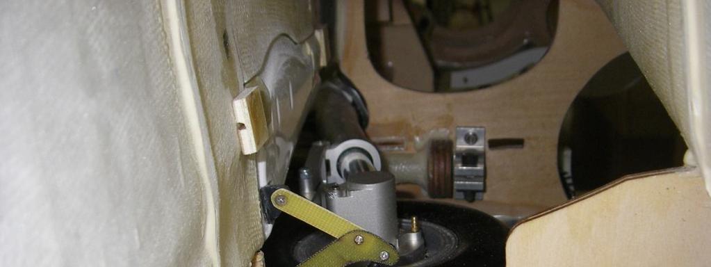
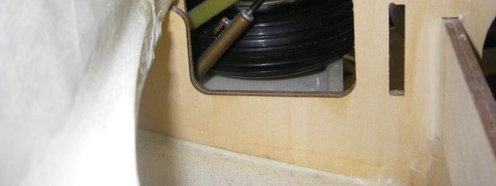
15 NOSE GEAR & DOORS Assembly & Operation Manual NOTE: If you have purchased the ARF PLUS PRO KIT proceed to page 19. On the pro kit all doors and LG already installed. Work on a secure and protective surface. This will protect the paint surface from unwanted dents. Mark each step. Photo 21 Photo 22 Photo 23 Landing gear blocks should have all have blind nuts installed already by factory. Trial fit nose leg to mount. Make sure actuator move gear fully up and down. Make sure no binding of gear to fuselage. Remove actuator from gear. Fit steering servo to. Centre servo and fit pushrod. Fit air tubing to nipples. Secure nose leg to mounts with 4 bolts. Locate 2 nose gear doors. Align and sand to fit. Glue hinges to doors. Trial fit and glue to fuselage. Make sure it operates correctly. Glue cylinder mounts to door. Trial fit cylinders and secure in position. Photo 24 Photo 25 Photo 26 P-15


16 Photo 27 Photo 28 Photo 29 Run all air tubing in harness. Make sure servo wires and air tubing do not interfere with operation. Refit actuator and secure with 4 screws. Locate front door. Make plywood brackets and secure to actuator. Glue door to plywood structure. Check operation. Make sure door is flush when gear is up. Photo 30 Photo 31 Photo 32 MAIN GEAR & DOORS Photo 33 Photo 34 P-16


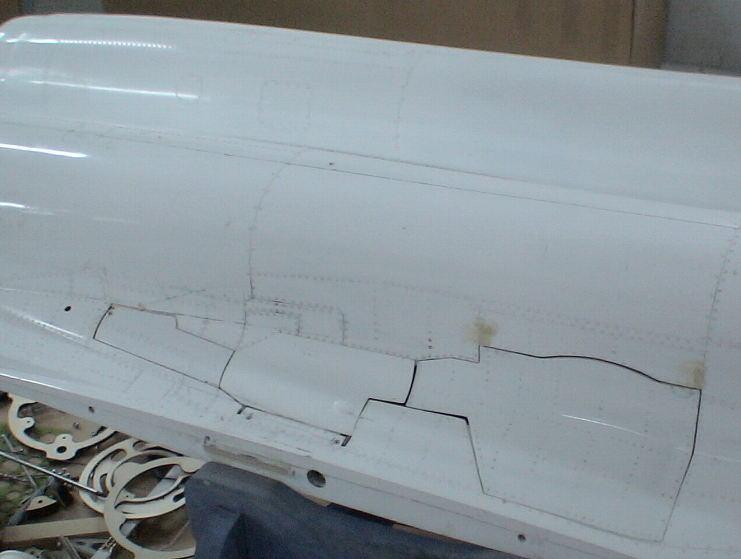
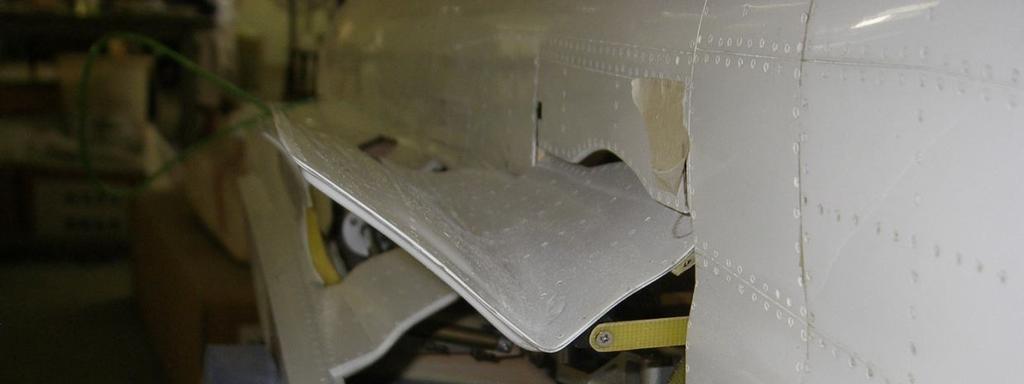
17 Photo 35 Photo 36 Photo 37 Holes should have factory installed blind nuts. Trail fit and sand fuselage if needed. Secure landing gear. Make sure gear can fully retract and lock in down position. Locate door 1. Trial fit and sand to shape. Manufacture hinge extensions from glass board and glue to door. Glue hinges to extensions. Trial fit door to fuselage and glue in position. Photo 38 Photo 39 Photo 40 Glue cylinder mount to wing tube insert and gear door. Fit cylinder. Photo 41 Photo 42 Photo 43 Locate door 2. Trial fit and sand to shape. Glue 2 steel pins as hinges. Glue cylinder mount to door. P-17


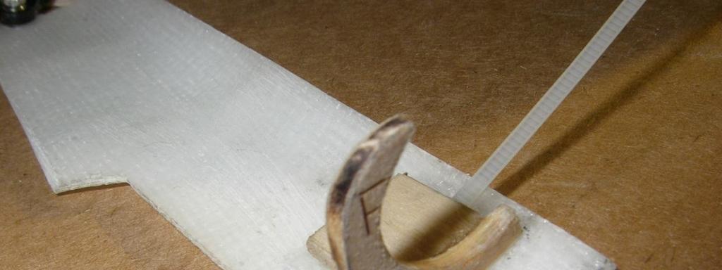
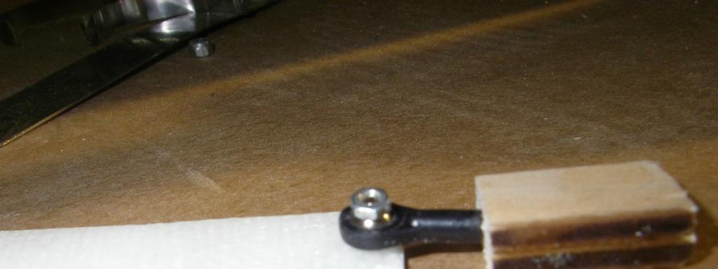

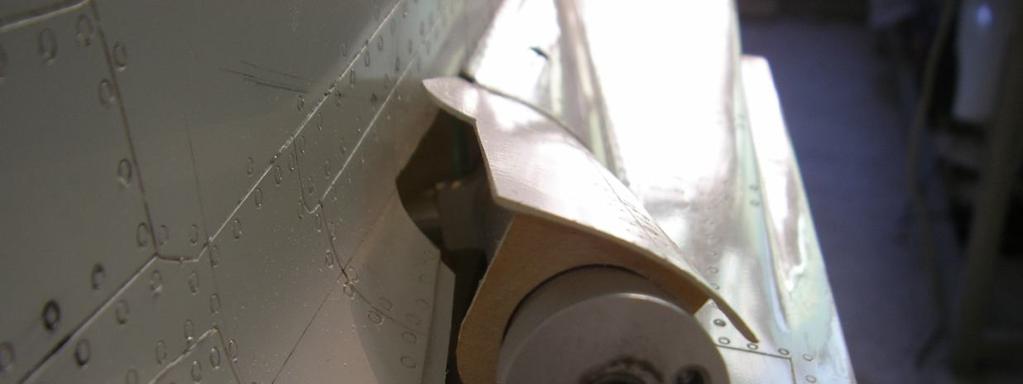
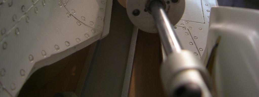
18 Photo 44 Photo 45 Photo 46 Tape door in position and glue 2 slotted plywood blocks to form hinge. When happy with fit manufacture collapsible hinge support. (page48) Fit cylinder and check operation. Photo 47 Photo 48 Photo 49 Photo 50 Photo 51 Photo 52 Photo 53 Photo 54 Photo 55 Locate door 3 and glue plywood former to door. Manufacture hinge from ball joint. Cable tie door to actuating arm. Close all doors and adjust correct fit. P-18


19 TAIL PIPE Assembly & Operation Manual This section is for conventional bifurcated tail pipe. If you are installing the thrust vectoring tail pipe, please skip to next page. Photo 56 Photo 57 Photo 58 Slide the tail pipe into the fuselage. Align tail pipe so that bellmouth sits just behind rear former. Secure tail pipe to rear former. Secure bellmouth with silicon to pipe. Photo 59 Photo 60 Photo 61 Slide nozzle over rear pipe and bolt to former. Glue former in tail feathers. Secure tail feather to pipe. Make sure all parts line up and are in straight line. The rear tailpipe must slide over tail pipe. Bolt rear nozzle to fuselage using 3 bolts. P-19


20 TAIL PIPE THRUST VECTORING Photo 62 Photo 63 Photo 64 Photo 65 Photo 66 Photo 67 Secure the 2 vectoring servos to mounts. Make sure servos are centered. Make up 2 pushrods for X and Y axis. Fit pushrods to servos. Slide rear tail pipe into nozze. Bolt rear pipe to nozzle. Bolt stand-offs to nozzle former. Bolt vector pipe to stand-offs. Photo 68 Photo 69 Photo 70 Slide nozzle over tail pipe and secure to fuselage with 3 bolts. Make sure pushrods move freely through nozzle section. Fit pushrods and use incidents meter to check 0 degree when servo horn is 90 degree. P-20


21 Photo 71 Photo 72 Photo 73 When happy with movement, remove vectoring pipe. Fit former to vectoring pipe Trail fit tail feather to former. Check clearance at nozzle. Tail feathers must be able to move 360 degrees. When happy glue with 30 minute epoxy. Refit vectoring pipe and check operation. Pipe should be able to move on X-Y axis. Photo 74 Photo 75 Photo 76 Repeat for other nozzle. P-21


22 FUEL CELLS Assembly & Operation Manual The fuel system is very important. A good installation will ensure trouble free operation and no flame outs due to air bubbles. Make use of an air trap. We recommend BVM UAT. Photo 78 Rinse tanks and make sure no foreign objects from manufacturing process stayed behind in tank. Do a pressure test and see if tank is secure no cracks on seam lines. Mark the top of tank. Also draw arrows to show direction of flow. Make up 3 x fuel fittings. Make sure clunk will reach all corners of tank. Photo 80 When you cut copper pipe, make sure to ream ends for better operation. Fit fitting to tank. Tighten bolt and do an air test. Make sure no leaks are present. Do not over tighten bolt. Silicon glue tank to bottom of fuselage and inlet duct. Install UAT in cockpit area of fuselage. Photo 79 Plumb tanks with tygon tubing. Photo 81 Fill and drain tanks! Check that no air are trapped in tanks. UAT must drain last and stay full of fuel all the time during draining. Paint bottom of fuselage and tank with heat resistant paint. Photo 83 Photo 82 P-22
23 FUEL CELL DIAGRAM Assembly & Operation Manual Photo 84 P-23


24 TURBINE INSTALLATION Photo 85 Please follow the instructions supplied with your turbine. Secure turbine to turbine rail via hatch on top of fuselage. Leave gap of 25mm between NGV and tailpipe. Run all turbine wires and power cables on opposite side of servo wires. Always secure all wires in harness. I would suggest you install a FOD. This will save you money in the long run. Install fuel pump close to UAT. We recommend to make use of a mechanical shut off valve as well. Secure all Festo pipes with cable ties. Make sure fuel filter and gas canister are mounted vertical. Install NiCad or LiPo battery in nose. I always put a fuse holder inline with power cable. Photo 86 Photo 87 P-24

25 AIR SYSTEM Photo 88 Glue the air tanks with silicon to fuselage. I have installed the 2 large tanks for operation of gears,doors and brakes. Fit the 2 filler valves and 2 pressure gauges onto accessory tray. Plumb the landing gear, door and brake system by using color air tubing. T all same color tubing together until a single pipe emerge. Route all 5 pipes to the accessory tray in front of fuselage. The air system will consist of : Air up, Air down retracts (2) Air up, Air down doors (2) Air out brakes (1) Total of 7 pipes There are 2 options available for the air system: Mechanical Valves or Electronic Valves For mechanical valves you will need 2 x 2 way valves and 1 x 1way valve with 3 servos and sequencer. Photo 89 The electronic EV5U will do all the above in a single unit. This will make installation much simpler and save space. Air leaks can damage your model! Please do a thorough check for air leaks. Make sure the system can hold pressure for at least an hour in the up and down position. Do not rush this installation. P-25
26 AIR DIAGRAM Photo 90 Diagram for retracts P-26

27 COCKPIT AND CANOPY Assembly & Operation Manual Slide cockpit in position. Use Dremel drum sander to sand fuselage canopy frame to clear cockpit. Cut cockpit to size. Photo 91 Use small 2mm self tap screws to secure cockpit in position. P-27


28 EQUIPMENT INSTALLATION INTO VIPERJET Equipment installation is a personal venture. There is one golden rule: Do it as neat and logical as possible! This will make faultfinding and service of components easier. The Viper basically consist of 6 circuits! 1. Servo wires 2. Power cables 3. Data cables 4. Pneumatic pipes 5. Fuel pipes 6. RX cable Please try and separate these circuits as far as possible. It is advisable not to run RX cables near any kind of electrical fields. Make all switches and filler valves and charging sockets easy accessible. Photo 92 Photo 93 Photo 95 Photo 94 P-28
29 BEFORE YOU FLY It is assumed that the builder of this kit has acquired the basic skills and knowledge necessary to make a safe and functional radio control installation into a model. Therefore, these notes are intended only to assist that experience. Travel adjust measured at root. 1. Elevator 40mm 2. Rudder 30mm 3. Aileron 25mm 4. Flaps take off 15 degrees 5. Flaps landing 45 degrees 6. VT 20 degrees each way NOTE : Make sure flaps travel same. Use Powerbox or Matchbox to match travel. Flaps should be deployed in landing circuit only below 90mph CG Weight PSI Power TX RX Speed Timer 220mm 230mm from leading edge at root. Empty tanks, UAT full and wheels down. Dry weight will be between 28 and 35 lbs depending equipment psi for pneumatic system JR equipment operates on 4.8V. If you use 5 cell packs please use a voltage regulator. I prefer 4 cell 2400mA RX packs. Lipo packs are standard with Powerbox installations Do a complete range check before flight. Do this with turbine running. Follow manufacturers instructions. Set the maximum speed to 180mph! The prototype were tested with Jetcat P-160 and P-180 turbines. More powerful turbines require extra care and extra reinforcing. A timer can safe your model. Get into the habit of programming the timer. P-29
30 Take-Off Do some taxi tests before your flight! Make sure you are familiar with all settings and make sure the model track straight on the ground without rudder input. Choose a fine day for the maiden flight. Do not force a maiden flight! Murphy will visit you! Select take off flap or flight mode 1 and open throttle. Gently pull back on stick 30m down the runway. The MIG will be in the air faster than you expect. Raise the flaps and gear at safe altitude and let the model sit on rails. Slow Flight Most of the first flight should be utilized to get familiar with the slow speed flight characteristics. Select the flaps to the takeoff position; there should be no pitch change. Extend the gear and select full landing flaps; adjust the power to maintain level flight and a speed of about 80 90mph. Climb to a safe altitude and slow the model to the edge of a stall to know where that edge is. Landing Fly a complete circuit before landing. Approach from the downwind side and lower the LG. Fly a complete circuit getting use to the power required. On the next circuit lower the flaps. If you have a headwind be very careful not to get below the power curve on the downwind side. Align the model and use throttle to control the descent! The elevators will stay very active even at low speed. Flare the model just before touch down. Let the model roll out and apply brakes. Taxi back and do necessary adjustments to customize MIG for your need! We at Skymaster wish you many happy flights with your MIG29! Regards, Anton Lin and Skymaster Team! P-30
XXL INSTRUCTIONS MANUAL. Spesifications Avanti S
 INSTRUCTIONS MANUAL XXL Spesifications Avanti S Type : T.A.V.S Airex Carbon Composite Length : 112 (2860mm) Span : 97.6 (2480mm) Weight : 38 44Lbs ( 18 20 Kg) Engine : 40 45 Lbs (18 21 Kg) trust Avanti
1/4 Scale Almost-Ready-To-Fly RC Model Assembly and operations manual
 1/4 Scale Almost-Ready-To-Fly RC Model Assembly and operations manual Spesifications Scale : 1/4 Length : 112.5 : (2850mm) Span : 90 : (2288mm) Weight : 18Kg Engine : Jetcat SPT5 Radio : 12 Ch (8 servos)
1/2.5 Scale Almost-Ready-To-Fly RC Jet Assembly and operations manual
 1/2.5 Scale Almost-Ready-To-Fly RC Jet Assembly and operations manual Spesifications Type : T.A.V.S ARF PRO Scale : 1/2.5 Length : 133 : (3380mm) Span : 140 : (3560mm) Weight : 25 30Kg Turbine: 1 x 21-31
1/7.75 Scale Almost-Ready-To-Fly RC Jet Assembly and operations manual
 1/7.75 Scale Almost-Ready-To-Fly RC Jet Assembly and operations manual Spesifications Type : T.A.V.S ARF PRO Scale : 1/7.75 Length : 80,3 : (2040mm) Span : 87,8 : (2230mm) Weight : 27-29 Lbs ( 13-14 Kg)
1/5 Scale Almost-Ready-To-Fly RC Jet Assembly and operations manual
 1/5 Scale Almost-Ready-To-Fly RC Jet Assembly and operations manual Spesifications Type : T.A.V.S ARF PRO Scale : 1/5th Length : 90.2 : (2230mm) Span : 91 : (2310mm) Weight : 42 46 Lbs ( 19 21 Kg) Engine
1/3.75 Scale Almost-Ready-To-Fly RC Jet Assembly and operations manual
 1/3.75 Scale Almost-Ready-To-Fly RC Jet Assembly and operations manual Spesifications Hawk 100 Type : T.A.V.S ARF PRO Scale : 1/3.75 Length : 131 : (3330mm) Span : 107 : (2700mm) no missiles Weight : 55
Dassault Aviation FALCON 7 X. for Jet CAT P160. Assembly Manual. AVIATION Design
 Dassault Aviation FALCON 7 X for Jet CAT P160 Assembly Manual AVIATION Design ZI le chenet, 91490 Milly La Foret, FRANCE Tel : 33 1 64 98 93 93 Fax : 33 1 64 98 93 88 E-mail : aviation.design@wanadoo.fr
VENTRIX. Dear Customer, Thank you for purchase our Ventrix Sport jet product
 VENTRIX Dear Customer, Thank you for purchase our Ventrix Sport jet product Following you can find greater information for build and fly this model. Before you get started building and setting-up your
Turbinator-2 Build Manual
 Turbinator-2 Build Manual Thank you for your purchase of the Turbinator-2 sport jet by Boomerang RC Jets. This RC Jet IS NOT A TOY and should only be flown and operated by experienced RC Turbine Pilots.
Assembly Manual. Version 01/01/2006
 Assembly Manual ZI le chenet, 91490 Milly La Foret, FRANCE Tel : 33 1 64 98 93 93 Fax : 33 1 64 98 93 88 E-mail : aviation.design@wanadoo.fr www.adjets.com Version 01/01/2006 INTRODUCTION is our new jet
Instruction Manual book
 Instruction Manual book Item code:bh133 SPECIFICATION Wingspan : 1,400 mm 55.12 in. Length : 1,350 mm 53.15 in. Weight : 3.7 kg 8.14 Lbs. Radio : 08-09 channels. Servo : 08-09 servos. EDF : Turingy SK3
Instruction Manual book
 Instruction Manual book ITEM CODE:BH118. SPECIFICATION Wingspan : 1,050 mm 41.34 inches. Length : 950mm 37.4 inches. Weight : 1 kg 2.2 lbs. Radio : 04 channels. Servo : 4 mini servos. Motor : KMS 2814/05
Assembly and Operating Manual. SPECIFICATION Length inch (640mm) Wing Span inch (705mm) Flying Weight oz (330g)
 Wing Span inch (705mm) Flying Weight oz (330g)") Assembly and Operating Manual SPECIFICATION Length 25.19 inch (640mm) Wing Span 27.76 inch (705mm) Flying Weight 11.64 oz (330g) Dear customer, Assembly and Operating manual VIPER The Radio Control System
Assembly and Operating Manual SPECIFICATION Length 25.19 inch (640mm) Wing Span 27.76 inch (705mm) Flying Weight 11.64 oz (330g) Dear customer, Assembly and Operating manual VIPER The Radio Control System
Instruction Manual book
 book ITEM CODE:BH 115. SPECIFICATION Wingspan : 6,000 mm 236,22 in. Length : 2,740 mm 107,87 in. Weight : 17.5kg 38.5Lbs. Radio : 08 channels. Servo : 07-08 HS-5685MH(HITEC) Battery : 2 Cells-Li-Po 7.4V
Assembly Manual. AVIATION Design
 SCORPION Assembly Manual AVIATION Design ZI le chenet, 91490 Milly La Foret, FRANCE Tel : 33 1 64 98 93 93 Fax : 33 1 64 98 93 88 E-mail : aviation.design@wanadoo.fr www.adjets.com Version 01/09/2009 AVIATION
Table of Contents. Tail Wheel Assembly Installation.. page 01. Stabilizer Installation.. page 02. Fin Installation.. page 03
 Table of Contents Tail Wheel Assembly Installation.. page 01 Stabilizer Installation.. page 02 Fin Installation.. page 03 Elevator and Rudder Hinge Installation.. page 04 Rudder Controls.. page 05 Elevator
F-84G ThunderJet Construction Manual. Introduction
 Introduction Thank you for purchasing the PST Jets F-84G ThunderJet kit. The PST F-84G is designed for use with 20 to 30 lb turbine engines. The PST F-84G is based on an accurate scale outline of the Republic
Instruction Manual book
 book Item code:bh131 SPECIFICATION Wingspan : 3,000 mm 118.1 in. Length : 1,600 mm 62.99 in. Weight : 2.2 kg 4.84 Lbs. Radio : 05 channels. Servo : 06 mini servos. Electric Motor: BOOST 40 Battery : 3celIs
MiG-29 Retract Kit (for the HET-RC Mini Air Retract System)
") MiG-29 Retract Kit (for the HET-RC Mini Air Retract System) The MiG-29 Retract Kit was designed to allow the easy installation of the HET-RC mini Air Retract system into the twin EDF MiG-29. We recommend
MiG-29 Retract Kit (for the HET-RC Mini Air Retract System) The MiG-29 Retract Kit was designed to allow the easy installation of the HET-RC mini Air Retract system into the twin EDF MiG-29. We recommend
I n s t r u c t i o n M a n u a l. Instruction Manual SPECIFICATION
 I n s t r u c t i o n M a n u a l Instruction Manual SPECIFICATION - Wingspan: 3200mm (125,9 in) - Length: 1650mm (64,9 in) - Flying weight: 3000gr 3200gr - Wing area: 64.5 dm2 - Wing loading: 46g/dm2
MS:159 ASSEMBLY MANUAL. Graphics and specifications may change without notice.
 ASSEMBLY MANUAL MS:159 Graphics and specifications may change without notice. Specifications: Wing span ----------------------------61.8in (157cm). Wing area -----------------1100.5sq.in (71.0sq dm). Weight
for AMT Pegasus jet engine or for Jet Cat P-120 / P-160 Assembly Manual AVIATION Design
 for AMT Pegasus jet engine or for Jet Cat P-120 / P-160 Assembly Manual AVIATION Design ZI le chenet, 91490 Milly La Foret, FRANCE Tel : 33 1 64 98 93 93 Fax : 33 1 64 98 93 88 E-mail : aviation.design@wanadoo.fr
PilotRC Trainer USER MANUAL
 PilotRC Trainer USER MANUAL Introduction Thank you for purchasing our Trainer plane. we strive to achieve a good quality quick build ARF aircraft. It requires the least amount of assembly of any ARF kit
F3D-30 ARF ASSEMBLY MANUAL
 F3D-30 ARF ASSEMBLY MANUAL This Manuel is the sole property of Kangke Industrial USA, Inc. Reproducing any part without the consent of Kangke Industrial USA, Inc. is a lawful violation. Kangke Industrial
96in Super Decathlon ARF
 96in Super Decathlon ARF Instruction Manual Specifications Wingspan: 96in (2438mm) Length: 63.5 in (1614mm) Weight: Approx. 13lbs (6.5kg) 1 Dear Customer, Congratulations on your purchase of Super Decathlon
51in Aerobatic Series Sukhoi SU-26M Almost-Ready-to-Fly. Instruction Manual. Specifications
 51in Aerobatic Series Sukhoi SU-26M Almost-Ready-to-Fly Instruction Manual Specifications Wingspan: 51.2 in (1300mm) Length: 51.2 in (1300mm) Wing Area: 581 sq in (37.5sq dm) Flying Weight: 3.5 lb (1600g)
Instruction Manual book
 book ITEM CODE:BH 145 SPECIFICATION Wingspan: 6,000mm 236.22 in. Length : 2,800 mm 110.24 in. Weight : 18.5 kg 40.7 Lbs. Parts listing required (not included). Radio : 07-08 channels. Servo : 09-10 standard
Instruction Manual. Specification:
 Instruction Manual L O W Specification: Wingspan: 133 cm (52.3 inches) Length : 104 cm (40.9 inches) Weight : 1790gr Engine : 25-32 two stroke Radio : 4 channel - 4 servo W I N G KIT CONTENTS: We have
RECOMMENDED MOTOR AND BATTERY SET UP
 SPECIFICATION - Wingspan: 6000mm (236.2 in) - Length: 2873mm (113.1 in) - Flying weight: 14-18 kg - Wing area: 219.4 dm2 - Wing loading: 64g/dm2 - Wing type: HQ airfoils - Covering type: Genuine ORACOVER
Instruction Manual book
 book ITEM CODE:BH 139 SPECIFICATION Wingspan : 1,450mm 57.09 in. Length : 1,140 mm 44.88 in. Weight : 3.3kg 7.26 Lbs. Radio : 05 channels. Servo : 07 mini servos+ 3servos Retracts (FUTABA S3170G) EDF:
Instruction Manual book
 Instruction Manual book ITEM CODE:BH135 SPECIFICATION Wingspan : 4,200mm. 163.35 in. Length : 2,100 mm. 82.68 in. Weight : 7,6 kg. 16.72lbs Radio : 07 channels. Servo : 05 06 standard high torque servos,
Assembly Manual For. Wingspan: 88 in Wing area: sp in Length: 78.8 in Engine: 50CC.
 Assembly Manual For Wingspan: 88 in Wing area: 1479.8 sp in Length: 78.8 in Engine: 50CC www.pilot-rc.com INTRODUCTION Thank you for purchasing our new 50 cc model. We strive to bring you the most complete
Instruction Manual book
 Instruction Manual book ITEM CODE:BH118. SPECIFICATION Wingspan : 1,050 mm 41.34 inches. Length : 950mm 37.4 inches. Weight : 1 kg 2.2 lbs. Radio : 04 channels. Servo : 4 mini servos. Motor : BL2215/20
Assembly and operating instructions. Assembly and Operating Manual
 Assembly and operating instructions Assembly and Operating Manual Dear customer, Assembly and Operating Manual The radio control system Glued joints, suitable adhesives Congratulations on your choice of
EXTRA 330LX. Specifications: Code: SEA274. Graphics and specifications may change without notice. ASSEMBLY MANUAL
 ASSEMBLY MANUAL EXTRA 330LX Code: SEA274 Graphics and specifications may change without notice. Specifications: Wingspan---------------82.0 in (208.2 cm). Wing area---------------1349.4 sq.in ( 87.1 sq.dm).
MARACANA ASSEMBLY INSTRUCTION .40 ARF LOW WING TRAINER RADIO CONTROL MODEL. Every body can fly
 RADIO CONTROL MODEL ASSEMBLY INSTRUCTION MARACANA.40 ARF LOW WING TRAINER Every body can fly VQA085 EP GP You can use both Gas or Electric power Wingspan: 59in.(1520mm) Fuselage length: 48in.(1220mm) Engine:
Assembly and operating instructions. Assembly and Operating Manual
 Assembly and operating instructions Assembly and Operating Manual Dear customer, Assembly and Operating Manual The radio control system Glued joints, suitable adhesives Congratulations on your choice of
Pitts Challenger m (100cc) MANUAL
 MANUAL") Pitts Challenger 87 2.20m (100cc) MANUAL 1- Introduction: WELCOME TO THE PILOT-RC TEAM! Thank you for choosing a Pilot-Rc plane as your next model. We hope that you enjoy many successful and exhilarating
Pitts Challenger 87 2.20m (100cc) MANUAL 1- Introduction: WELCOME TO THE PILOT-RC TEAM! Thank you for choosing a Pilot-Rc plane as your next model. We hope that you enjoy many successful and exhilarating
MS:176 ASSEMBLY MANUAL. Graphics and specifications may change without notice.
 ASSEMBLY MANUAL MS:176 Graphics and specifications may change without notice. Specifications: Wing span ------------------------------98.4in (250cm). Wing area ----------------1576.4sq.in (101.7sq dm).
RADIO CONTROL MODEL HURRICANE
 RADIO CONTROL MODEL VQAA040G VQAA040B HURRINE Almost ready to fly SPECIFITIONS Wingspan...63 in. / 161cm Length...50 in. / 129cm Engine...50~60 2T / 70~90 4T Or Electric equivalent. RC Functions: Motor
the leading edge of the wing, at the fuselage - Length: 1540mm (60.6 in) 10% expo; High: 15mm up/down, 10% expo - Wing area: 40dm2
 10% expo; High: 15mm up/down, 10% expo - Wing area: 40dm2") SPECIFICATION - Gravity CG: 165-170 mm (6.5-6.7 in) Back from - Wingspan: 1400mm (55.1 in) the leading edge of the wing, at the fuselage - Length: 1540mm (60.6 in) - Control throw Ailerons: Low: 12mm up/down,
SPECIFICATION - Gravity CG: 165-170 mm (6.5-6.7 in) Back from - Wingspan: 1400mm (55.1 in) the leading edge of the wing, at the fuselage - Length: 1540mm (60.6 in) - Control throw Ailerons: Low: 12mm up/down,
Instruction Manual book
 book SPECIFICATION Wingspan : 1,450 mm 57.09 in. Length : 1,200mm 47.24in. Weight : 3.1 kg 6.82 Lbs. Radio : 05 channels. Servo : 07 servos. Engine : 61-75 2 stroke. 91 4 stroke. Made in Vietnam. This
: 7 channel - 9 servo, Hi-Torque ( Minimum 6 kg ).
.") g Wingspan : 1820mm (71.65 inches) Length : 1625mm (63.98 inches) Weight : 6900gr Engine : 25cc - 35cc Radio : 7 channel - 9 servo, Hi-Torque ( Minimum 6 kg ). KIT CONTENTS: We have organized the parts
g Wingspan : 1820mm (71.65 inches) Length : 1625mm (63.98 inches) Weight : 6900gr Engine : 25cc - 35cc Radio : 7 channel - 9 servo, Hi-Torque ( Minimum 6 kg ). KIT CONTENTS: We have organized the parts
ALMOST READY TO FLY. Wing Span in cm. 2
 ASSEMBLY MANUAL ALMOST READY TO FLY MS:X9 Specifications Wing Span --------------------------61.4 in ---------------------------156cm. 2 Wing Area --------------------------606.1 sq.in ------------------
Assembly and Operating Manual
 Dear customer, Assembly and Operating Manual The radio control system Glued joints, suitable adhesives Congratulations on your choice of a factory-assembled model aircraft from the SKYANGEL Hummingbird
Fei Bau 1/6 th scale F 15-Eagle
 Fei Bau 1/6 th scale F 15-Eagle Developed and written by Luke Cullen The following instructions are developed based on using twin turbines. The ARF kit can be optioned from the factory for either twin
: 6 channel - 9 servo
 g Wingspan : 2005mm (78.94 inches) Length : 1640mm (64.57 inches) Weight : 6400g - 6600g Engine : 25cc - 35cc Radio : 6 channel - 9 servo KIT CONTENTS: We have organized the parts as they come out of
MS:183 ASSEMBLY MANUAL. Graphics and specifications may change without notice.
 MS:183 ASSEMBLY MANUAL Graphics and specifications may change without notice. Specifications: Wing span ------------------------------79.9in (203cm). Wing area -----------------1165.6sq.in (75.2sq dm).
I/C FLIGHT GUIDELINES
 SPECIFICATION - Wingspan: 3500mm (137.8 in) - Length: 1650mm (64.96 in) - Flying weight: 3700-4000 gr - Wing area: 75 dm2 - Wing loading: 49g/dm2 - Wing type: HQ profile - Covering type: Genuine ORACOVER
Assembly and Operating Manual
 Assembly and Operating Manual Dear customer, Congratulations on your choice of a factory-assembled model aircraft from the SKYANGEL Hummingbird range and thank you for placing your trust in us. Very little
Aviator Pro 120 ARF. Instruction Manual. Specifications
 Aviator Pro 120 ARF Instruction Manual Specifications Wingspan: 110 in (2800 mm) Length: 74 in (1870 mm) Wing Area: 1581sq in (102 sq dm) Weight: 11.4-13.4 lbs (5190-6100 g) Dear Customer, Congratulations
RECOMMENDED EDF AND BATTERY SET UP
 SPECIFICATION - Wingspan: 1150mm (45.3 in) - Length: 1587mm (62.5 in) - Flying weight: 5.0-5.3 kg - Wing area: 40dm2 - Wing loading: 125g/dm2 - Wing type: Naca airfoils - Covering type: Genuine ORACOVER
Instruction Manual book
 book SPECIFICATION Wingspan : 2,310 mm 90.94 in. Length : 1,750 mm 68.90 in. Weight : 8.4 kg 18.48 Lbs. Radio : 06 channels. Servo : 09 servos + 2 mini servos (elevator). Engine : 45-55CC gas. Made in
Instruction Manual book
 Instruction Manual book SPECIFICATION Wingspan : 1,800mm. 70.87 in. Length : 1,350 mm. 53.15in. Weight : 3.6kg. 7.92lbs. Parts Listing required (not included). Glow Engine : 55-61 2 stroke. 91 4 stroke.
Instruction Manual book
 Instruction Manual book Item code:bh117 SPECIFICATION Wingspan : 2,100 mm 82.68 in. Length : 1,875 mm 73.82 in. Weight : 7.5 kg 16.5 Lbs. Parts listing required (not included) Radio : 08 channels. Servo
(Glider) ASSEMBLY MANUAL
 ASSEMBLY MANUAL") (Glider) MS:132 ASSEMBLY MANUAL Graphics and specifications may change without notice. Specifications: Wing span ------------------------------118.1in (300cm). Wing area ---------------------902.1sq.in
(Glider) MS:132 ASSEMBLY MANUAL Graphics and specifications may change without notice. Specifications: Wing span ------------------------------118.1in (300cm). Wing area ---------------------902.1sq.in
Instruction Manual book
 book (pusher propeller) ITEM CODE:BH 142 SPECIFICATION Wingspan : 1,450mm 57.09 in. Length : 1,165 mm 45.87 in. Weight : 3.3kg 7.26 Lbs. Radio : 05 channels. Servo : 07 size (29 x 13 x 30) mm. Electric
SBACH SCALE 1:4 ½ ARF
 SPECIFICATION - Wingspan: 1663mm (65.5 in) - Length: 1638mm (64.5 in) - Flying weight: 4700-5200 gr - Wing area: 56 dm2 - Wing loading: 85g/dm2 - Wing type: Naca airfoils - Covering type: Genuine ORACOVER
Instruction Manual book
 Instruction Manual book Item code:bh144 SPECIFICATION Wingspan : 1,400 mm 55.12 in. Length : 1,350 mm 53.15 in. Weight : 4 kg 8.8 Lbs. Empty Weight: 1.9 kg 4.18 lbs Radio : 08 channels. Servo : 08 size
Instruction Manual book
 Instruction Manual book ITEM CODE: BH122. SPECIFICATION Wingspan : 2,200 mm 86.61 in. Length : 1,640 mm 64.57 in. Weight : 6.5 kg 14.3Lbs. Parts listing required (not included). Radio : 8 channels. Servo
RECOMMENDED MOTOR AND BATTERY SET UP
 SPECIFICATION - Wingspan: 1404mm (55.3in) - Length: 1134mm (44. 6 in) - Flying weight: 3.2-3.4 kg - Covering type: Genuine ORACOVER - Spinner size: scale type (not included) - Radio: 4 channel minimum
Instruction Manual book
 Instruction Manual book Item code:bh117 SPECIFICATION Wingspan : 2,100 mm 82.68 in. Length : 1,875 mm 73.82 in. Weight : 7.5 kg 16.5 Lbs. Radio : 08 channels. Servo : 09 servos. Engine : 33-45cc gas. Made
to fly. Most hardware included and all replacement parts are available.
 Instruction Manual The Thunderbolt P47 was perhaps the greatest of world war II in terms of all round performance and capability Phoenix Model has recreated a 2C - 60 class engine (or 4c 91 class) It was
29% KATANA ARF ASSEMBLY MANUAL
 29% KATANA ARF ASSEMBLY MANUAL Required but not included Aircraft Specifications: 4 channel radio and supporting equipment Wing Span 84 Engine 3.2-4.2 c.i. (50-60 c.c.) Wing Area 1270 Sq. in. Fuel Tank
Instruction Manual book
 Instruction Manual book ITEM CODE:BH 140 SPECIFICATION Wingspan : 2,050mm 80.71 in. Length : 1,840 mm 72.41 in. Weight : 6.8kg 14.96 Lbs. Radio : 07 channels. Servo : 09 servos. Engine: O.S GT 33 CC gas.
Instruction Manual book
 book ITEM CODE:BH 124 SPECIFICATION Wingspan : 2,240 mm 88.19 in. Length : 1,625 mm 63.98 in. Weight : 6,4 kg 14.08Lbs. Radio : 08 channels. Servo : 09 servos. Engine : 26-35cc Gas. Made in Vietnam. This
Instruction Manual book
 book SPECIFICATION Wingspan : 1,920 mm 75.59 in. Length : 1,560 mm 61.42 in. Weight : 5 kg 11.00Lbs. Radio : 06 channels. Servo : 09 servos. Engine : 120 4 stroke. Made in Vietnam. This instruction manual
RECOMMENDED MOTOR AND BATTERY SET UP
 SPECIFICATION - Wingspan: 1410mm (55.5 in) - Length: 1278mm (50.3 in) - Flying weight: 3.2-3.4 kg - Wing area: 41.3 dm2 - Wing loading: 75g/dm2 - Wing type: Naca airfoils - Covering type: Genuine ORACOVER
SIZE.120 OR 30CC SCALE 1:5 ARF
 PC21 PILATUS MK2 SIZE.120 OR 30CC SCALE 1:5 ARF SPECIFICATION - Wingspan: 1772mm (69.72in) - Length: 2019mm (79.5 in) - Flying weight: 6.4-7.2 kg - Wing area: 57.6 dm2 - Wing loading: 113g/dm2 - Wing type:
Instruction Manual. Wingspan : 2270mm (89.37 inches) : 1870mm (73.62 inches) : 7400gr gr. : 4 channel - 6 standard servo.
 : 1870mm (73.62 inches) : 7400gr gr. : 4 channel - 6 standard servo.") Wingspan : 2270mm (89.37 inches) g Length : 1870mm (73.62 inches) Weight : 7400gr - 7600gr Radio : 4 channel - 6 standard servo Engine : 25cc-35cc KIT CONTENTS: We have organized the parts as they come
Wingspan : 2270mm (89.37 inches) g Length : 1870mm (73.62 inches) Weight : 7400gr - 7600gr Radio : 4 channel - 6 standard servo Engine : 25cc-35cc KIT CONTENTS: We have organized the parts as they come
AVIATOR 25 ARF Almost Ready-to-Fly
 AVIATOR 25 ARF Almost Ready-to-Fly Instruction Manual Specifications Wingspan: 54.3 in (1380mm) Length: 45.2 in (1150mm) Wing Area: 438 sq in (34sq dm) Flying Weight: 3.8 b (1700g) Dear Customer, Congratulations
RADIO CONTROL MODEL ASSEMBLY INSTRUCTIONS. Wasp
 RADIO CONTROL MODEL ASSEMBLY INSTRUCTIONS Wasp TRAINER Almost ready-to-fly Wingspan 1520mm Fuselage length 1105mm Engine: 40-46 2T / 52-60 4T Electric Motor: 600-700W Radio: 5 channel / 4-5 servo RC Functions:
RECOMMENDED MOTOR AND BATTERY SET UP
 SPECIFICATION - Wingspan: 2190mm (86.2 in) - Length: 1907mm (75 in) - Flying weight: 9000-12000 gr - Wing area: 92 dm2 - Wing loading: 98g/dm2 - Wing type: Naca airfoils - Retract gear type: Air-retract
Assembly and Operating Manual
 Assembly and Operating Manual SCREAMER Specification: *Length: 20"(510 mm) *Wing span: 22 4/5"(580 mm) *Flying weight: 10 4/5 oz (305g) Dear customer, Congratulations on your choice of a factory-assembled
Instruction Manual book
 Instruction Manual book SPECIFICATION Wingspan : 2,170 mm 85.43 in. Length : 1,760 mm 69.29 in. Weight : 6.3 kg 13.86 Lbs. Radio : 06 channels. Servo : 08 servos. Engine : 45-50CC Gas. Made in Vietnam.
F3P Instruction Manual
 Before use, please read the explanations carefully! F3P Instruction Manual Specifications Fuselage length: 884mm ( 34. Bin ) Wingspan : 845mm ( 33. 2in) Flying Weight : 135-160g (with battery) Additional
MEMO. No.4341 Specification: Wing Span: 29.1 (740mm) Length: 36.6 (930mm) 2. Warranty
 Length: 36.6 (930mm) 2. Warranty") MEMO No.4341 Specification: Wing Span: 29.1 (740mm) Length: 36.6 (930mm) 2 Wing Area: 299 sq.in. (19.29 dm ) Weight: 18.9oz. (536.5g) 2 Wing loading: 0.58 oz./sq.ft (27.8g/dm ) Motor: OBL 29/27-07A Warranty
MEMO No.4341 Specification: Wing Span: 29.1 (740mm) Length: 36.6 (930mm) 2 Wing Area: 299 sq.in. (19.29 dm ) Weight: 18.9oz. (536.5g) 2 Wing loading: 0.58 oz./sq.ft (27.8g/dm ) Motor: OBL 29/27-07A Warranty
Instruction Manual book
 book ITEM CODE: BH109 SPECIFICATION Wingspan : 2,200mm. 86.61 in. Length : 1,976 mm. 77.80in. Weight : 8.3 kg. 18.26 lbs. Part listing required (not included) Glow Engine : 55 CC Gas Servo : 9 servos.
Instruction Manual book
 book ITEM CODE:BH 72 SPECIFICATION Wingspan : 2,350 mm 92.52 in. Length : 1,730 mm 68.11 in. Weight : 6.4 kg 14.08 Lbs. Radio : 06 channels. Servo : 08 servos. Engine : OS. GT22-26cc gas. Made in Vietnam.
YAK54 MK2. GP/EP size.120/20cc SCALE 1:4 ¾ ARF. Instruction Manual. version. version
 Instruction Manual GP EP version version GP/EP size.10/0cc SCALE 1:4 ¾ ARF SPECIFICATION - Wingspan: 168 (66.3 in) - Length: 1605mm (63.1 in) - Flying weight: 4700-500 gr - Wing area: 54.7 dm - Wing loading:
48in Sbach-342. Instruction Manual. Specifications
 48in Sbach-342 Instruction Manual Specifications Wingspan: 48in (1219mm) Length: 46in (1163mm) Wing Area: 471sq in (30.4sq dm) Flying Weight: 1.8-2.0lb (800-900g) Dear Customer, www.valuehobby.com/48in-s342-arf.html
35MM Series Nano F15. Assembly and Operating Manual
 35MM Series 2011 Assembly and Operating Manual SPECIFICATION: Length: 21-3/5"(550mm) Wing Span: 15-3/5"(395mm) Flying Weight: 5-4/5oz (165g.) Nano F15 Dear customer, Congratulations on your choice of a
Instruction Manual book
 Instruction Manual book SPECIFICATION Wingspan : 1,920 mm 75.59 in. Length : 1,560 mm 61.42 in. Weight : 5 kg 11.00Lbs. Radio : 06 channels. Servo : 09 servos. Engine : 120 4 stroke. Made in Vietnam. JU87-STUKA
Radio control model INSTRUCTION MANUAL PYLON RACING. Wingspan: 1148mm (45.2 ) Radio : 4 channels Engine : two-stroke
 Radio : 4 channels Engine : two-stroke") VQA038 VQA039 Radio control model INSTRUCTION MANUAL MAGIC PYLON RACING Wingspan: 1148mm (45.2 ) Radio : 4 channels Engine :.25 -.32 two-stroke WARNING! This radio control model is not a toy. If modified
VQA038 VQA039 Radio control model INSTRUCTION MANUAL MAGIC PYLON RACING Wingspan: 1148mm (45.2 ) Radio : 4 channels Engine :.25 -.32 two-stroke WARNING! This radio control model is not a toy. If modified
PITTS 12 R/C SPORT-SCALE AIRCRAFT ASSEMBLY AND INSTRUCTION MANUAL. Copyright Century UK Limited 2012
 PITTS 12 R/C SPORT-SCALE AIRCRAFT ASSEMBLY AND INSTRUCTION MANUAL 1 Warning: This radio controlled model is not a toy. It requires skill to fly and is not recommended for use by beginners. It should not
Instruction Manual book
 book ITEM CODE:BH 136 SPECIFICATION Wingspan : 2,000mm 78.74 in. Length : 1,760 mm 69.29 in. Weight : 6.8kg 14.96 Lbs. Parts listing required (not included). Engine : 0.S GT 33cc gas Radio : 07 channels.
Gent EPP. Before use please read the explanations carefully
 Before use please read the explanations carefully Gent EPP Instruction Manual Specifications Fuselage length 900mm 35in Wingspan 820mm 32in Flying Weight 210 240g with battery Additional Required Equipment
INSTRUCTION MANUAL BOOK
 INSTRUCTION MANUAL BOOK ITEM CODE BH57. SPECIFICATION Wingspan: 1,470 mm. 57.87 in. Length : 1,180 mm. 46.46 in. Weight : 2.7 Kg. 5.94 Lbs. Engine : 46 cu.in 2 stroke. 52 cu.in 4 stroke. Radio : 4 channels.
Instruction Manual book
 book SPECIFICATION Wingspan : 2,080 mm 81.89 in. Length : 1,680 mm 66.14 in. Weight : 6.2 kg 13.64 Lbs. Radio : 06 channels. Servo : 06 servos. Engine : 30-35 CC Gas(FUJI IMVAC). Made in Vietnam. This
Assembly and Operating Manual. 3D cap-232. Specification: *Length: 25-9/10"(655mm) *Wing Span: 29-3/5"(750mm) *Flying Weight: 15-9/10 oz (450g)
 *Wing Span: 29-3/5(750mm) *Flying Weight: 15-9/10 oz (450g)") Assembly and Operating Manual 3D cap-232 Specification: *Length: 25-9/10"(655mm) *Wing Span: 29-3/5"(750mm) *Flying Weight: 15-9/10 oz (450g) Dear customer, Congratulations on your choice of a factory-assembled
Assembly and Operating Manual 3D cap-232 Specification: *Length: 25-9/10"(655mm) *Wing Span: 29-3/5"(750mm) *Flying Weight: 15-9/10 oz (450g) Dear customer, Congratulations on your choice of a factory-assembled
Instruction Manual book
 Instruction Manual book SPECIFICATION Wingspan : 1,920 mm 75.59 in. Length : 1,560 mm 61.42 in. Weight : 5 kg 11.00Lbs. Radio : 06 channels. Servo : 09 servos. Engine : 120 4 stroke. Made in Vietnam. JU87-STUKA
Lanier R/C F-4 Phantom
 Lanier R/C.40-.46 F-4 Phantom Almost Ready to Fly WARNING! THIS IS NOT A TOY! THIS IS NOT A BEGINNERS AIRPLANE This R/C kit and the model you will build from it is not a toy! It is capable of serious bodily
ASSEMBLY MANUAL SIZE
 SIZE.75 -.91 ASSEMBLY MANUAL MS:123 Graphics and specifications may change without notice. Specifications: Wing span ----------------------------66.9in (170cm). Wing area -----------------761.1sq.in (49.1sq
WE GET PEOPLE FLYING T-34
 TM WE GET PEOPLE FLYING T-34 Mentor ASSEMBLY MANUAL Specifications Wingspan:... 57.25 in (1454 mm) Length:... 45 in (1146 mm) Wing Area:... 555 sq in (35.8 sq dm) Weight:... 6 7 lb (2.7 kg 3.2 kg) Radio:...
PilotRC EDGE USER MANUAL. WINGSPAN:1710mm LENGTH:1554mm
 PilotRC EDGE540 67 USER MANUAL WINGSPAN:1710mm LENGTH:1554mm Introduction Thank you for purchasing our Edge 540 plane. we strive to achieve a good quality quick build ARF aircraft. It requires the least
MS:136 ASSEMBLY MANUAL. Graphics and specifications may change without notice.
 ASSEMBLY MANUAL MS:136 Graphics and specifications may change without notice. Specifications: Wing span ----------------------------79.5in (202cm). Wing area -----------------965.7sq.in (62.3sq dm). Weight
RECOMMENDED MOTOR AND BATTERY SET UP
 SPECIFICATION - Wingspan: 2567mm (101in) - Length: 2190mm (86.2 in) - Flying weight: 11-13 kg - Wing area: 101 dm2 - Wing loading: 99g/dm2 - Wing type: Naca airfoils - Covering type: Genuine ORACOVER -
STORCH. Parts. Additional items needed to complete the Storch
 STORCH Parts Fuse with Greenhouse- (Attached) Left and right wing panel Horizontal and vertical stab 2 Wing center blocks 2 Carbon spares for wing 1 Undercarriage with wheels 2 Undercarriage shocks 2 Carbon
Assembly and Operating Manual HR-100. Specification: *Length: 41-7/10"(1060 mm) *Wing span: 49-1/5"(1250 mm) *Flying weight: 45.
 *Wing span: 49-1/5(1250 mm) *Flying weight: 45.") Assembly and Operating Manual HR-100 Specification: *Length: 41-7/10"(1060 mm) *Wing span: 49-1/5"(1250 mm) *Flying weight: 45.9 oz (1300g) Dear customer, Congratulations on your choice of a factory-assembled
Assembly and Operating Manual HR-100 Specification: *Length: 41-7/10"(1060 mm) *Wing span: 49-1/5"(1250 mm) *Flying weight: 45.9 oz (1300g) Dear customer, Congratulations on your choice of a factory-assembled
Instruction Manual book
 Instruction Manual book SPECIFICATION Wingspan : 1,780 mm 70.08 in. Length : 1,520 mm 59.84 in. Weight : 4.8 kg 10.56 Lbs. Radio : 06 channels. Servo : 09 servos. Engine : 120 4stroke Made in Vietnam.