OPERATOR S MANUAL. Auxiliary Engine Pallet. 40 Hp Engine-Driven Hydraulic Power Pack
|
|
|
- Lorena Greene
- 5 years ago
- Views:
Transcription


 898-4588")
1 OPERATOR S MANUAL Auxiliary Engine Pallet 40 Hp Engine-Driven Hydraulic Power Pack QUALITY YOU CAN SEE, PEOPLE YOU CAN TRUST TM M-B Companies, Inc Wisconsin Ave. P. O. Box 200 New Holstein, WI (920) or FAX: (920) Publication: AEP /31/12
2
3 TABLE OF CONTENTS INTRODUCTION...3 Operator s Manual...3 Identification Numbers...3 SAFETY...4 Safety Alerts...4 Safety Decals...5 Pre-Start Guidelines...4 Operation Guidelines...4 Maintenance Guidelines...5 ASSEMBLY...6 CONTROLS AND FEATURES...7 OPERATION...10 Pre-Start Checks...10 Remote Transmitter...10 Starting The Engine...10 Running The Broom...10 Shutting Off The Engine...10 Transporting...10 MAINTENANCE...11 Maintenance Schedule...11 Lubrication...11 Pressure Manifold...12 Installing a new Transmitter or Receiver...12 STORAGE...13 Storage...13 TROUBLESHOOTING...14 SERVICE PARTS...17 WARRANTY...18 Publication: AEP M-B Companies, Inc. 07/31/12
4 NOTES Publication: AEP M-B Companies, Inc. 07/31/12


5 INTRODUCTION OPERATOR S MANUAL You must read, understand and comply with all the safety and operating instructions in this manual before attempting to set-up and operate the Auxiliary Engine Pallet. Failure to comply with the safety and operating instructions can result in loss of machine control, serious personal injury to you and/or bystanders, and risk of equipment and property damage. IDENTIFICATION NUMBERS When contacting your authorized dealer for information, replacement parts or service, you MUST have the model and serial number of your unit. Record the serial number in the space provided. The serial number plate/decal can be found in the location shown in Figure 1. Model Name/Number: Date Purchased: Serial #: Serial number plate is located behind this panel. Figure 1 Publication: AEP M-B Companies, Inc. 07/31/12 3
6 SAFETY ALERTS Signal words and alert symbols notify of important safety precautions. SAFETY DANGER! Indicates a hazardous situation which, if not avoided, will result in serious injury or death. WARNING! CAUTION! Indicates a hazardous situation which, if not avoided, could result in serious injury or death. Indicates a hazardous situation or unsafe practice which, if not avoided, could result in minor or moderate injury or property damage. SAFETY DECALS Reading this manual and the safety instructions it contains will provide you with the necessary basic knowledge to operate this equipment safely and effectively. We have also placed several safety labels on the unit to remind you of this important information while you are operating your unit. All DANGER, WARNING, CAUTION, and instructional messages on your unit should be carefully read and obeyed. Bodily injury can result when these instructions are not followed. The information is for your safety and it is important. These labels will act as a constant visual reminder to you, and others who may use the equipment, to follow the safety instructions necessary for safe, effective operation. If any of these labels are lost or damaged, replace them at once. See you local dealer for replacements. PRE-START GUIDELINES Install any covers or guards which may have been removed for shipping purposes. Before starting equipment, walk around equipment, making a visual inspection that all safety devices are properly installed and secured. Check that all hardware, fasteners, hydraulic fittings, etc. are in good condition and properly fastened. Replace any fatigued or damaged items with proper replacements. Personnel who are not required to be in the work area should be kept away. Never start the equipment unless you are absolutely certain that everyone in the area is clear of the machine and aware it is being started. Follow the manufacturer s recommended start-up procedure. OPERATION GUIDELINES Read, understand and follow all instructions in the manual and on the unit before starting. To avoid serious injury or death, do not modify equipment. Any modifications made to equipment can be dangerous and can void equipment warranty. Never operate equipment with covers or guards removed. Rotating parts can cause severe injury. Keep hands, feet, hair, jewelry and clothing away from all moving parts. Never defeat a safety device to make a task easier. Always wear proper apparel when operating equipment; safety glasses, face shield or goggles, ear protection, and dust mask. Tie hair back. Never wear loose clothing or jewelry that could get caught in moving parts. Only allow responsible adults who are familiar with the instructions, to operate the unit (local regulations can restrict operator age). Clear the area of objects such as rocks, toys, wire, etc., which could be picked up and thrown. 4 Publication: AEP M-B Companies, Inc. 07/31/12
7 SAFETY Be aware of surroundings. Be sure the area is clear of other people, bystanders or pets. Stop unit if anyone enters the area. Always look down and behind before and while traveling in reverse. Be aware of discharge direction and do not point discharge at anyone. Do not point the discharge at glass enclosures, automobiles, or windows. Always stand clear of the discharge area when operating this unit. Disengage all clutches and PTO s before starting engine. Never leave a running machine unattended. Always disengage the attachment and traction controls, lower the attachment, set the park brake, stop the engine and remove the ignition key before leaving the machine. Operate only in daylight or good artificial light. Never carry passengers. Do not operate the unit while under the influence of drugs, alcohol or other medication. Watch for traffic when operating near or crossing roadways. Use extra care when loading or unloading the unit into a trailer or truck. Keep in mind the operator is responsible for accidents occurring to other people or property. Data indicates that operators, age 60 years and above, are involved in a large percentage of power equipment-related injuries. These operators should evaluate their ability to operate the unit safely enough to protect themselves and others from injury. All operators should seek and obtain professional and practical instruction. Protect eyes, face and head from objects that may be thrown from unit. Wear appropriate hearing protection. Always wear substantial footwear and appropriate clothing. Wear footwear that improves traction on slippery slopes. DO NOT wear long scarves or loose clothing that could become entangled in moving parts. Abnormal Vibrations are a warning of trouble. Striking a foreign object can damage unit. Stop unit and engine. Wait for all moving parts to stop. Inspect unit and make any necessary repairs before restart. Never place your hands or any part of your body or clothing inside or near any moving part while unit is running. Stop engine before: refueling, cleaning, making adjustments or removing the attachment assembly. Follow the drive unit manufacturer s recommendations for wheel weights or counter weights. Make any adjustments before operating unit. Do not touch parts which may be hot from operation. Allow such parts to cool before attempting to service the unit. Before using, always visually check that hardware is present, intact and secure. Replace worn or damaged parts. Never operate the machine with damaged guards, or without safety protective devices in place. Follow the manufacturer s recommendations for towing weight restrictions and procedures. Original purchaser of this unit was instructed by the seller on safe and proper operation. If unit is to be used by someone other than original purchaser; loaned, rented or sold, ALWAYS provide this manual and any needed safety training before operation. The Operator must understand the functions and parameters of all controls and how to operate, as well as how to STOP in an Emergency. NOTE: All reference to left, right, front, or rear are given from the operator position and facing forward. MAINTENANCE GUIDELINES Maintain or replace safety and instruction decals/labels as necessary. Never run a unit in an enclosed area. Keep nuts and bolts tight and keep equipment in good condition. Never tamper with safety devices. Check their proper operation regularly and make necessary repairs if they are not functioning properly. Keep unit free of debris and build-up. Clean up any oil spillage. Never make adjustments or repairs with the engine running unless specified otherwise in the engine manufacture s manual. Components are subject to wear, damage, and deterioration. Frequently check components and replace with the manufacturer s recommended parts, when necessary. Check control operation frequently. Adjust and service as necessary. Use only factory authorized parts when making repairs. Always comply with factory specifications on all settings and adjustments. Only authorized service locations should be utilized for major service and repair requirements. Never attempt to make your own repairs on this unit unless you have been properly trained. Improper service procedures can result in hazardous operation, equipment damage and voiding the manufacturer s warranty. Stop engine on tractor and set parking brake before performing any adjustments on the machinery. Do not disassemble a pressurized system unless properly trained and equipped with adequate tooling. Escaping hydraulic fluid under pressure can have sufficient force to penetrate the skin, causing serious injury. Before operation, be sure that all hydraulic connections are tight and hoses are not damaged. Relieve pressure in system before making adjustments. Oils and fluids can be very hot under pressure. Use caution and allow the system to cool before beginning maintenance work. Never operate or pressurize one of these systems with worn or damaged components. Replace hoses, fittings, valves or other components which appear defective. Never adjust pressurized systems beyond recommended levels to achieve higher operating pressures. NEVER search for hydraulic leaks with only your hands. Use cardboard or a piece of wood. For engine equipped models, follow specific engine manufacturer s recommended service intervals for dirty/dusty environments. Publication: AEP M-B Companies, Inc. 07/31/12 5

8 INTRODUCTION ASSEMBLY The auxiliary engine pallet is shipped fully assembled. The remote transmitter with batteries is secured to the top of the unit. 1. Remove packing materials. Inspect the unit for damage. If any damage is visible contact M-B Company before adding fluids or attempting to start the hydraulic power pack. 2. Insert the batteries into the remote transmitter. The green LED should blink two times per second when transmitter and receiver are communicating properly. Refer to the section on remote transmitter. 3. Fill hydraulic reservoir with ISO 32 or greater hydraulic fluid to the proper level. Fill to approximately 3/4 full on level/temp sight gauge. If operating in temps of 0-40 F (-17-4 C) use ISO 32 cold weather type fluid or Dextron III ATF. 4. Connect hydraulic hoses to attachment. Remove caps and store in safe location for future use or for servicing. Connect hydraulic lines for angle and raise functions as required for use with the specific attachment. Connect hydraulic motor hoses M for motor high pressure and MT for motor low pressure (return to tank). See Figure 2. Left 1/4 inch 3000 psi min hose. Used to raise broom head. Right Left Raise Lower/Float On/Off Figure 3 8. Once the engine pallet power pack has been properly set-up, refer to the OPERATION section within this manual to operate for a 15 minute break-in period. Cycle all the controls several times while running the broom to remove any air in the hydraulic system. 9. After this break-in period, check oil levels in the hydraulic reservoir and engine. Refer to the engine manufacturer s Owner/Operator Manual for specific guidelines. Right 1/4 inch 3000 psi min hose. Used to angle the broom head. 1 inch 2000 psi max hose. Used for motor return port. 1 inch 2000 psi min hose. Used for motor pressure port. Figure 2 5. Fill fuel tank with fuel. Refer to the engine owner/operator manual for the correct type and grade of fuel. 6. Check connections at battery posts. Black negative (-) cable to negative (-) posts. Red positive (+) cable to positive (+) post. Tighten connections. 7. Verify all other electrical connections have not come loose or detached during shipment (Figure 3). Publication: AEP M-B Companies, Inc. 07/31/12

9 CONTROLS INTRODUCTION AND FEATURES Hydraulic Fluid Sight Gauge 2. Fuel Cap 3. Hydraulic Fluid Cap 4. Engine Exhaust Outlet 5. Engine Access Panel 6. Electric/Hydraulic Valve Assembly 7. Fuel Sight Gauges 8. Main Power Switch Figure 4 Publication: AEP M-B Companies, Inc. 07/31/12 7
10 CONTROLS INTRODUCTION AND FEATURES Hydraulic Fluid Filter 2. Hydraulic Cooling Fan 3. Battery Access Panel Figure 5 Publication: AEP M-B Companies, Inc. 07/31/12

11 CONTROLS INTRODUCTION AND FEATURES Engine Throttle & Choke Solenoids (2) 2. Engine Oil Filter 3. Engine Oil Fill Cap 4. Engine Air Cleaner 5. Engine Oil Level Dipstick 6. Engine Exhaust Muffler Amp Control Harness Fuse Figure 6 Publication: AEP M-B Companies, Inc. 07/31/12 9

12 INTRODUCTION OPERATION PRE-START CHECKS 1. Visually inspect equipment and mounting hardware to ensure that all parts are secure and tightened properly. 2. Check fasteners that secure power pack to mobile equipment. 3. Check for oil leaks and loose hose connections. 4. Check electrical connections. 5. Check that filters are free of any dirt and debris that would restrict air flow. REMOTE TRANSMITTER The remote transmitter has buttons to run the engine and control broom functions. There are two LED s that blink to indicate communication status. Battery Compartment Engine Controls Broom Controls Figure 7 LED s Two AA Alkaline batteries will provide approximately 30 hours of continuous operation. Activate the remote by pressing and holding the POWER button for at least 2 seconds and release. To turn off the remote and turn off the engine, press and hold the POWER button for more than 3 seconds. The transmitter is designed with a power saving feature which turns the transmitter off after 4 hours if no buttons are pressed. There are red and green LED s both on the keypad of the transmitter and inside the receiver case. The green LED will blink 2 times per second when the transmitter and receiver are communicating. It will blink 1 time per second if there is no communication (i.e. - no power to the receiver). RUNNING THE BROOM 1. When the engine is warmed up, press the BROOM button to start the broom. CAUTION! Do not operate engine pallet product at temperatures above 80 F (26.6 C). Engine Warranty will be voided! NOTE: If the hydraulic fluid is cold, allow the broom to idle for 10 minutes. If the carrier vehicle is equipped with a lift cylinder, raise the broom off of the ground. 2. To change the angle of the broom head, press and hold the LEFT or RIGHT button. When the button is released the movement will stop. 3. If the carrier vehicle is equipped with a lift cylinder, the RAISE and LOWER buttons will lift the broom head and lower it. SHUTTING OFF THE ENGINE 1. Press the BROOM button to turn off the broom. 2. Lower the engine idle by pressing THROTTLE. 3. Let the engine idle for 5 minutes or until the hydraulic cooling fan turns off. 4. Press and hold the POWER button on the remote transmitter for more than 3 seconds to turn off the engine and transmitter. 5. Move the main power switch, on the top of the unit, to the OFF position. The switch will go from red to clear. TRANSPORTING Use the forklift openings on either end of the engine pallet for transporting. Use the lift hook holes for hoisting (Figure 8). DANGER! Do not lift the unit using the engine housing. This item could fail and the unit could drop. Lift Hook Openings STARTING THE ENGINE 1. Turn the remote transmitter on by pressing the POWER button. 2. Move the main power switch, on the top of the unit, to the ON position (switch will light up red). 3. Press START (and CHOKE if needed). Release buttons when engine starts. When the engine starts the speed will be at the high setting. 4. Use the THROTTLE button to toggle between high and low engine speed. Fork Lift Openings Fork Lift Openings Figure 8 Publication: AEP M-B Companies, Inc. 07/31/12
13 INTRODUCTION MAINTENANCE MAINTENANCE SCHEDULE DANGER! WARNING! Keep hands and clothing away from moving parts! Components may be hot from use! Oil cooler fan may turn ON even with engine OFF! Only perform Service with engine OFF, battery disconnected and after allowing hot parts to cool. Fluid escaping under pressure can puncture the skin and cause serious injury. Do not touch any hydraulic components until the engine has been turned off, hydraulic system depressurized and components disconnected. LUBRICATION NOTE: Grease points are noted with an applicable decal. Grease bearings and pivot points per the MAINTENANCE SCHEDULE using Chevron Ultra Duty II, Grade 2; or equivalent high-temp grease. Use an ISO 32 or greater hydraulic fluid. If operating in temps of 0-40 F (-17-4 C) use ISO 32 cold weather type fluid or Dextron III ATF. Service Performed Inspect all fasteners and mounting hardware and tighten as necessary. Check for loose hydraulic connections. Before Each Use Check engine oil level and fill as necessary. 1 Daily (8 Hrs) Every 25 Hours Every 50 Hours Every 250 Hours Annually Inspect engine air filter. 2 Check hydraulic oil level and fill as necessary. Check adjustments. Inspect and clean oil cooler of debris. Replace hydraulic oil filter. Replace hydraulic oil. 1 Replace per engine manufacturer s requirements. 2 Increase frequency to Daily (8 Hrs) if operating in dusty environment. NOTE: Maintenance pertaining to replacing oil and oil filter only refers to the independent hydraulic systems provided by M-B Co. Refer to the engine manufacturer s guidelines for maintenance intervals and proper care of engine. Publication: AEP M-B Companies, Inc. 07/31/12 11
14 PRESSURE MANIFOLD Broom performance is controlled by the hydraulic pressure. The valve assembly is preset at the factory. M-B Co recommends that this setting is not changed without consulting with M-B Customer Service. If the engine is stalling under load or overheating turn the unit off. Contact M-B Customer Service at Attachments Division. INSTALLING A NEW TRANSMITTER OR RECEIVER Each transmitter and receiver pair is synchronized together at the factory. If a new transmitter is needed, synchronizing is required. Refer to Figure 9 and use the following procedure: 1. Remove the cover of the receiver, making sure the power is applied. 2. Place the jumper across the address code jumper for >4 seconds. Both LED s will toggle at this point. Remove the jumper and store it on one pin. 3. On the transmitter, press and hold the POWER button, CHOKE button and RAISE button. Release all buttons. Both LEDs will blink together at this point. 4. Wait for a few seconds until the green LEDs begin to blink. 5. Synchronizing complete. 6. Replace the cover on the receiver. INTRODUCTION MAINTENANCE Figure 9 Publication: AEP M-B Companies, Inc. 07/31/12
15 STORAGE Store the unit in a location out of the sun and weather to prolong paint life. The hydraulic oil reservoir can become contaminated with moisture if the unit is not properly stored. Be sure oil reservoir cap is free from debris and accumulated snow before storing. The oil cooler fins should be inspected and cleaned if needed. INTRODUCTION STORAGE CAUTION! Do not use high pressure water or steam on the cooling fins. The fins will become damaged and reduce cooling capability. Disconnect the battery cables from the battery in the unit if it is going to be stored for more than a week. Properly clean the unit before storage and remove dirt, debris, salt, etc. to extend paint life. The engine has an oil cooler. See engine manual for recommended oil cooler cleaning intervals. If the unit is power-washed, all lubrication points should be greased before storage. Disconnect all electrical connections between the engine pallet and prime mover for extended storage to prevent battery drain. Prevent water from entering the filters and inspect them if contamination is suspected. Publication: AEP M-B Companies, Inc. 07/31/12 13
16 TROUBLESHOOTING INTRODUCTION Trouble Possible Cause Remedy Reduced or No hydraulic flow 1. Electric/manual valve not functioning or turned on. 2. No hydraulic pressure/flow. 3. ON/OFF Solenoid failed. 4. Engine Throttle switch at LOW RPM. 5. Throttle solenoid out of adjustment. No hydraulic pressure 1. Pump seal failure. 2. Pump drive coupler failing. 3. Hydraulic oil level low. Engine shuts down 1. Power demand overloading engine. 2. Low engine Oil. 3. Engine Overheating. 4. Engine Throttle switch at LOW RPM. Driven unit does not lift or angle. 1. Electric/manual valve not functioning. 2. No hydraulic pressure/flow to function. 3. Valve solenoids failed. Pump making noise or leaking fluid. 1. Pump intake blocked. 2. Shaft seal leaking 3. Pump suction pulling in air. Engine hesitating or stalling. 1. Hydraulic relief pressure too high. 2. Power demand overloading engine. 3. Engine fuel or air delivery problem. 4. Too cold to operate. Engine does not start. 1. Fuse blown (Figure 10 Fuse Location and Figure 11 Wiring Harness). 2. Battery low or disconnected. 3. Poor electrical ground. 4. Starter worn out. 5. Engine flooded with fuel. 6. Engine too hot. Remote control not functioning. 1. Batteries weak. LED blinks once per second. 2. Red LED blinks. 1. Check electrical connections. 2. Check hydraulic pump coupler. 3. Check solenoids. 4. Operate in HIGH Throttle. 5. Adjust to maintain throttle position. 1. Check pump operation. 2. Check pump coupler. 3. Check and fill reservoir to proper level. 1. Operate per instructions. Call M-B Customer Support 2. See Engine Manual. 3. See Engine Manual. 4. Operate per instructions. 1. Check electrical connections. 2. Check hydraulic circuit operation and fluid level. 3. Check solenoids. 1. Check inlet lines for obstructions. 2. Check and repair as necessary. 3. Check suction line and tighten clamps, check hydraulic oil level. 1. Adjust to factory setting. 2. Operate per instructions. 3. Consult engine manual. 4. Allow engine to warm-up. 1. Check fuses (Figure 10 Fuse Location and Figure 11 Wiring Harness) 2. Check battery voltage and connections. 3. Check ground wires, repair or clean as necessary. 4. Replace starter. 5. Choke solenoid out of adjustment. 6. See Engine Manual, wait to cool. 1. Replace Batteries. 2. Count light blinks between pauses. Check table below for faulty circuit. Then fix circuit 3. Receiver and transmitter not communicating. Error Code 1 Low battery Probable Cause 2 Faulty circuit to RUN 3 Faulty circuit to START 4 Faulty circuit to CHOKE 5 Faulty circuit to THROTTLE 6 Faulty circuit to RIGHT 7 Faulty circuit to LEFT 8 Faulty circuit to LOWER 9 Faulty circuit to RAISE 10 Faulty circuit to BROOM Error code number is the number of red light blinks between every pause. 3. If one component is new they may need to be synchronized. See section on Installing A New Transmitter Or Receiver. Publication: AEP M-B Companies, Inc. 07/31/12

17 TROUBLESHOOTING INTRODUCTION Throttle Relay Choke Relay 10 AMP Fuse Throttle 10 AMP Fuse Choke Figure 10 Fuse Location Publication: AEP M-B Companies, Inc. 07/31/12 15
18 TROUBLESHOOTING INTRODUCTION Figure 11 Wiring Harness Publication: AEP M-B Companies, Inc. 07/31/12
19 SERVICE INTRODUCTION PARTS Part Number Description Hydraulic Valve Assembly #20 Poppet, 2-Way, N.O #16 Pilot Spool Logic Element, 10 PSI #08 Needle Valve #08 Relief, Diff Area Poppet, 1200 PSI #08 Relief, Diff Area Poppet, 1400 PSI #08 Solenoid Valve, N.C #08 Check Valve, 25 PSI #08 Check Valve, 4 PSI #16 Vented, Spool Logic Element, 10 PSI #08 Solenoid, Spool, 5-Way, 3-Position #08 Coil, 12VDC, Metri-Pac, Zener Cap, Filler Neck Suction Strainer, Hydraulic Reservoir Repair Kit, Level/Temperature Sight Gauge, Hydraulic Reservoir Element, Hydraulic Filter Assembly Temperature Sensor, Hydraulic Oil Cooler Seal Kit, Hydraulic Pump Solenoids, Engine Throttle & Choke (2) Part Number Description Decal, Gasoline Decal, Hydraulic Oil Reservoir Decal Set (Contains decals below) Decal, Caution Hot Surface Decal, Caution Moving Parts No Reach Decal, Caution Read Manual Decal, Hydraulic Fluid Read Manual Please have your serial number (S/N) ready when contacting M-B Co. or an Authorized Dealer for replacement parts or service information. M-B Co. website: Wisconsin Ave. sales@m-bco.com P.O. Box 200 Phone: or New Holstein, WI FAX: Main Attachments Brush Dept Publication: AEP M-B Companies, Inc. 07/31/12 17
20 LIMITED WARRANTY Limited Warranty: Subject to the limitations set forth herein, M-B Companies, Inc. ( M -B ) warrants its products to be free from defects in material and workmanship for a period of twelve (12) months from the date of delivery of the product to its original owner, except that the warranty is twelve (12) months solely for the following products: Truck Mounted Pavement Marking Equipment, Airport Snow Removal Products, Attachment Products, Brushes, MSV Multi-Service Vehicles. Parts shall have a ninety (90) day warranty. This warranty is not transferable without the written consent of M-B. Notice: M-B s obligations under this Limite d Warranty are conditioned on M-B receiving, within the warranty period, written notice from Buyer specifying the nature of any alleged defect and requesting corrective action by Seller. Remedies: M-B, at its option, will repair or replace, or provide a credit to Buyer for, defective warranted items. If requested by M-B, products or parts for which a warranty claim is made shall be returned, transportation prepaid, to M-B s factory. Buyer shall not return any product for repair, replacement or credit without M-B s advance written consent. Other Manufacturer s Warran ty: On products furnished by M-B, but manufactured by any other manufacturer, the warranty of said manufacturer, if any, will be assigned to Buyer, if the said warranty is assignable. However, M-B does not represent or guarantee that such manufacturer will comply with any of the terms of the warranty of such manufacturer. Exclusions: Any improper use, operation beyond capacity, or substitution of parts not approved by M-B, or alteration or repair by others in such a manner as in M-B s judgment materially and/or adversely affects the product shall void this warranty. This warranty does not apply to defects caused by damage or unreasonable use while in the possession of the owner, including but not limited to: failure to provide reasonable and necessary maintenance, normal wear, routine tune ups or adjustments, improper handling or accidents, operation at speed or load conditions contrary to published specifications, improper or insufficient lubrication, or improper storage. Seller manufactures power brooms that mount to many makes and models of equipment. Seller attempts to ensure that the mounting frames fit correctly. However, the large number of tractor models, types and options currently available, compounded by frequent manufacturer design changes, may prevent Seller from supplying a frame that fits every unit correctly. Therefore, unless Buyer supplies drawing which detail the attachment points on the specific unit to which the broom will be mounted, Seller will not be responsible for the fit of the mounting frame. The batteries, tires, rubber material, brushes and material normally consumed in operation, and major components such as engines, air compressors, and hydraulic pumps and motors are excluded from this warranty but may be covered to the extent of any warranty received by M-B from its supplier if permitted by the terms of such warranty. Limitations of liability: M-B shall not be liable for any incidental, consequential, punitive or special damages of any kind, including, but not limited to, consequential labor costs or transportation charges in connection with the repair or replacement of defective parts, or lost time profits or expense which may have accrued because of said defect. M-B disclaims all other warranties, whether express or implied, including but not limited to any implied warranty of merchantability or fitness for a particular purpose. This warranty is exclusive remedy of buyer. This warranty cannot be extended, broadened or changed in any respect except in writing by an authorized officer of M-B. Notwithstanding anything in this warranty is to the contrary, in no event shall M-B s total liability hereunder exceed purchased price of the particular product. the M-B Companies, Inc. 07/31/12


21 OWNER'S MANUAL COMMAND PRO CH940-CH1000 HORIZONTAL CRANKSHAFT 1
22 Safety Precautions To ensure safe operations please read the following statements and understand their meaning. Also refer to your equipment owner's manual for other important safety information. This manual contains safety precautions which are explained below. Please read carefully. WARNING Warning is used to indicate the presence of a hazard that can cause severe personal injury,death, or substantial property damage if the warning is ignored. CAUTION Caution is used to indicate the presence of a hazard that will or can cause minor personal injury or property damage if the caution is ignored. NOTE Note is used to notify people of installation, operation, or maintenance information that is important but not hazard-related. For Your Safety! These precautions should be followed at all times. Failure to follow these precautions could result in injury to yourself and others. WARNING WARNING WARNING Explosive Fuel can cause fires and severe burns. Do not fill the fuel tank while the engine is hot or running. Explosive Fuel! Gasoline is extremely flammable and its vapors can explode if ignited. Store gasoline only in approved containers, in well ventilated, unoccupied buildings, away from sparks or flames. Do not fill the fuel tank while the engine is hot or running, since spilled fuel could ignite if it comes in contact with hot parts or sparks from ignition. Do not start the engine near spilled fuel. Never use gasoline as a cleaning agent. Rotating Parts can cause severe injury. Stay away while engine is in operation. Rotating Parts! Keep hands, feet, hair, and clothing away from all moving parts to prevent injury. Never operate the engine with covers, shrouds, or guards removed. CAUTION Electrical Shock can cause injury. Do not touch wires while engine is running. Hot Parts can cause severe burns. Do not touch engine while operating or just after stopping. Hot Parts! Engine components can get extremely hot from operation. To prevent severe burns, do not touch these areas while the engine is running, or immediately after it is turned off. Never operate the engine with heat shields or guards removed. California Proposition 65 Warning Engine exhaust from this product contains chemicals known to the State of California to cause cancer, birth defects, or other reproductive harm. Electrical Shock! Never touch electrical wires or components while the engine is running. They can be sources of electrical shock. 2
23 WARNING Safety Precautions (Cont.) WARNING WARNING Accidental Starts can cause severe injury or death. Disconnect and ground spark plug lead before servicing. Accidental Starts! Disabling engine. Accidental starting can cause severe injury or death. Before working on the engine or equipment, disable the engine as follows: 1) Disconnect the spark plug lead(s). 2) Disconnect negative (-) battery cable from battery. Carbon Monoxide can cause severe nausea, fainting or death. Avoid inhaling exhaust fumes, and never run the engine in a closed building or confined area. Lethal Exhaust Gases! Engine exhaust gases contain poisonous carbon monoxide. Carbon monoxide is odorless, colorless, and can cause death if inhaled. Avoid inhaling exhaust fumes, and never run the engine in a closed building or confined area. Explosive Gas can cause fires and severe acid burns. Charge battery only in a well ventilated area. Keep sources of ignition away. Explosive Gas! Batteries produce explosive hydrogen gas while being charged. To prevent a fire or explosion, charge batteries only in well ventilated areas. Keep sparks, open flames, and other sources of ignition away from the battery at all times. Keep batteries out of the reach of children. Remove all jewelry when servicing batteries. Before disconnecting the negative (-) ground cable, make sure all switches are OFF. If ON, a spark will occur at the ground cable terminal which could cause an explosion if hydrogen gas or gasoline vapors are present. Congratulations You have selected a fine four-cycle, twin cylinder, air-cooled engine. Kohler designs long life strength and on-the-job durability into each engine making a Kohler engine dependable dependability you can count on. Here are some reasons why: Efficient overhead valve design and full pressure lubrication provide maximum power, torque, and reliability under all operating conditions. Dependable, maintenance free electronic ignition ensures fast, easy starts time after time. Kohler engines are easy to service. All routine service areas (like the oil filter, dipstick, oil fill, air cleaner, spark plug, and carburetor) are easily and quickly accessible. Parts subject to the most wear and tear (like the cylinder liner and camshaft) are made from precision formulated cast iron. Every Kohler engine is backed by a worldwide network of over 10,000 distributors and dealers. Service support is just a phone call away. Call (U.S. & Canada) for Sales & Service assistance. Or visit To keep your engine in top operating condition, follow the maintenance procedures in this manual. 3

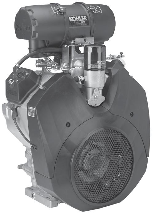
24 Air Cleaner Lifting Point Throttle Control Lever Oil Filter Choke Control Lever Carburetor Fuel Pump Oil Fill Lifting Strap Spark Plug Dipstick Cylinder Shrouds Blower Housing Screen Electric Starter Figure 1. Typical Command PRO Horizontal Shaft Engine. Oil Drain Plugs Oil Recommendations Using the proper type and weight of oil in the crankcase is extremely important. So is checking oil daily and changing oil regularly. It is also recommended that a consistent brand of oil be used. Failure to use the correct oil, or using dirty oil, causes premature engine wear and failure. Oil Type Use high quality detergent oil of API (American Petroleum Institute) service class SJ or higher. Select the viscosity based on the air temperature at the time of operation as shown in the following table. NOTE: Synthetic oils meeting the listed classifications may be used with oil changes performed at the recommended intervals. However to allow piston rings to properly seat, a new or rebuilt engine should be operated for at least 50 hours using standard petroleum based oil before switching to synthetic oil. A logo or symbol on oil containers identifies the API service class and SAE viscosity grade. See Figure 3. RECOMMENDED SAE VISCOSITY GRADES ** * 5W-20, 5W-30 10W-30 SAE 10W-30 API SERVICE SJ Kohler 10W-30 F C TEMPERATURE RANGE EXPECTED BEFORE NEXT OIL CHANGE * Use of synthetic oil having 5W-20 or 5W-30 rating is acceptable, up to 4 C (40 F) ** Synthetic oils will provide better starting in extreme cold below 23 C (-10 F) Figure 2. Viscosity Grades Table. Figure 3. Oil Container Logo. Refer to Maintenance Instructions beginning on page 8 for detailed oil check, oil change, and oil filter change procedures. NOTE: Using other than service class SJ or higher oil or extending oil change intervals longer than recommended can cause engine damage. 4
25 Fuel Recommendations WARNING: Explosive Fuel! Gasoline is extremely flammable and its vapors can explode if ignited. Store gasoline only in approved containers, in well ventilated, unoccupied buildings, away from sparks or flames. Do not fill the fuel tank while the engine is hot or running, since spilled fuel could ignite if it comes in contact with hot parts or sparks from ignition. Do not start the engine near spilled fuel. Never use gasoline as a cleaning agent. General Recommendations Purchase gasoline in small quantities that can be used within 30 days and store only in clean, approved containers. Do not use gasoline left over from the previous season unless treated with a fuel stabilizer (refer to Storage), to minimize gum deposits and ensure easy starting. Do not use gasoline containing Methanol, or add oil to the gasoline. Do not overfill the fuel tank. Leave room for the fuel to expand. Fuel Type For best results use only clean, fresh, unleaded gasoline with a pump sticker octane rating of 87 or higher. In countries using the Research method, it should be 90 octane minimum. Unleaded gasoline is recommended as it leaves less combustion chamber deposits and reduces harmful exhaust emissions. Leaded gasoline is not recommended and must not be used in any models where exhaust emissions are regulated. Gasoline/Alcohol blends Gasohol (up to 10% ethyl alcohol, 90% unleaded gasoline by volume) is approved as a fuel for Kohler engines. Other gasoline/alcohol blends including E20 and E85 are not to be used and not approved. Any failures resulting from use of these fuels will not be warranted. Gasoline/Ether blends Methyl Tertiary Butyl Ether (MTBE) and unleaded gasoline blends (up to a maximum of 15% MTBE by volume) are approved as a fuel for Kohler engines. Other gasoline/ether blends are not approved. Engine Identification Numbers When ordering parts, or in any communication involving an engine, always give the Model, Specification, and Serial Numbers of the engine. The engine identification numbers appear on a decal affixed to the engine shrouding. Include letter suffixes, if there are any. Record your engine identification numbers on the identification label below (Figure 4) for future reference. Figure 4. Engine Identification Label. The Emission Compliance Period referred to on the Emission Control or Air Index label indicates the number of operating hours for which the engine has been shown to meet Federal emission requirements. The following table provides the Engine Compliance Period (in hours) associated with the category descriptor found on the certification label. Emission Compliance Period (Hours) EPA Refer to certification label for engine displacement. Exhaust Emission Control System for models CH940- CH1000 is EM. Model Designation Model CH980 for example: C designates Command engine, H designates horizontal crankshaft, and 980 indicates the numerical model designation. A letter suffix designates a specific version as follows: Suffix S IMPORTANT ENGINE INFORMATION THIS ENGINE MEETS EMISSION REGS FOR U.S. EPA PH 2 SMALL OFF ROAD ENGINES AND CA 2006 AND LATER LSI ENGINES FAMILY DISPL. (CC) MODEL NO. SPEC. NO. SERIAL NO. BUILD DATE OEM PROD. NO. EMISSION COMPLIANCE PERIOD: EPA: CERTIFIED ON: REFER TO OWNER'S MANUAL FOR HP RATING, SAFETY, MAINTENANCE AND ADJUSTMENTS KOHLER CO. KOHLER, WISCONSIN USA IMPORTANT ENGINE INFORMATION THIS ENGINE MEETS EMISSION REGS FOR U.S. EPA 2006 AND LATER AND EC STAGE II (SN:4) SI SMALL OFF ROAD ENGINES AND CA 2006 AND LATER LSI ENGINES FAMILY TYPE APP DISPL. (CC) MODEL NO. SPEC. NO. SERIAL NO. BUILD DATE OEM PROD. NO. EMISSION COMPLIANCE PERIOD: EPA: CERTIFIED ON: REFER TO OWNER'S MANUAL FOR HP RATING, SAFETY, MAINTENANCE AND ADJUSTMENTS KohlerEngines.com KOHLER CO. KOHLER, WISCONSIN USA Category A 1000 hours Designates Electric Start 5


26 Pre-Start Checklist Check oil level. Add oil if low. Do not overfill. Check fuel level. Add fuel if low. Operating Instructions Also read the operating instructions of the equipment this engine powers. Check cooling air intake areas and external surfaces of engine. Make sure they are clean and unobstructed. (B) (B) Check that the air cleaner components and all shrouds, equipment covers, and guards are in place and securely fastened. Check that any clutches or transmissions are disengaged or placed in neutral. This is especially important on equipment with hydrostatic drive. The shift lever must be exactly in neutral to prevent resistance which could keep the engine from starting. Throttle and Choke Control Linkage Setup The throttle and choke levers on these engines allow remote mounted control operation from either side. The linkage for the throttle and choke is connected in one of the two available hole locations; A or B in the control levers. Hole location A in each lever is used for Outer Pull actuation. Hole Location B used for Inner Pull actuation. Most engines will have the control linkage connected in Location A, the primary location. If the application requires opposite side control direction or function, unhook the link(s) from the small clip and reconnect in the other hole location. See Figures 5 and 6. Linkages Connected Here Figure 6. Throttle and Choke Control Linkage in Inner Pull Configuration. WARNING: Lethal Exhaust Gases! Engine exhaust gases contain poisonous carbon monoxide. Carbon monoxide is odorless, colorless, and can cause death if inhaled. Avoid inhaling exhaust fumes, and never run the engine in a closed building or confined area. Cold Weather Starting Hints 1. Be sure to use the proper oil for the temperature expected. See Figure 2 on page Disengage all possible external loads. 3. Be sure the battery is in good condition. A warm battery has much more starting capacity than a cold battery. 4. Use fresh winter grade fuel. NOTE: Winter grade gasoline has higher volatility to improve starting. Do not use gasoline left over from summer. (A) (A) Starting 1. Place the throttle control midway between the SLOW and FAST positions. Place the choke control into the ON position. See Figures 7 and 8. Linkages Connected Here Figure 5. Throttle and Choke Control Linkage in Outer Pull Configuration. 6
. See your Kohler Engine Service Dealer for service assistance. Throttle Lever Figure 7. Location of Control Levers.")

27 If the starter does not turn the engine over, shut off starter immediately. Do not make further attempts to start the engine until the condition is corrected. Do not jump start using another battery (refer to Battery on this page). See your Kohler Engine Service Dealer for service assistance. Throttle Lever Figure 7. Location of Control Levers. Control Lever Knobs Choke Lever 3. For a Cold Engine Gradually return the choke control to the OFF position after the engine starts and warms up. The engine/equipment may be operated during the warm-up period, but it may be necessary to leave the choke partially on until the engine warms up. 4. For a Warm Engine Return choke to OFF position as soon as engine starts. Stopping 1. Remove the load by disengaging all PTO driven attachments. 2. Position the throttle control somewhere between half and full throttle; then stop the engine. Control Panel Figure 8. Optional Control Panel with Engine Mounted Controls. 2. Start the engine by activating the key switch. Release the switch as soon as the engine starts. NOTE: NOTE: Do not crank the engine continuously for more than 10 seconds at a time. If the engine does not start, allow a 60 second cool down period between starting attempts. Failure to follow these guidelines can burn out, or permanently damage, the starter motor. Upon start-up, a metallic ticking may occur. This is caused by hydraulic lifter leakdown during storage. Run the engine for 5 minutes. The noise will normally cease in the first minute. If noise continues, run the engine at mid-throttle for 20 minutes. If noise persists, take the engine to your local authorized Kohler Engine Service Dealer. Battery A 12 volt battery is normally used. Refer to the operating instructions of the equipment this engine powers for specific battery requirements. If the battery charge is not sufficient to crank the engine, recharge the battery (see page 14). Operating Angle of Operation This engine will operate continuously at angles up to 25. Check oil level to assure crankcase oil level is at the F mark on the dipstick. Refer to the operating instructions of the equipment this engine powers. Because of equipment design or application, there may be more stringent restrictions regarding the angle of operation. NOTE: Do not operate this engine continuously at angles exceeding 25 in any direction. Engine damage could result from insufficient lubrication. NOTE: If the engine develops sufficient speed to disengage the starter but does not keep running (a false start), engine rotation must be allowed to come to a complete stop before attempting to restart the engine. If the starter is engaged while the flywheel is rotating, the starter pinion and flywheel ring gear may clash resulting in damage to the starter. Cooling NOTE: If debris builds up on the grass screen or other cooling air intake areas, stop the engine immediately and clean. Operating the engine with blocked or dirty air intake and cooling areas can cause extensive damage due to overheating. 7
28 WARNING: Hot Parts! Engine components can get extremely hot from operation. To prevent severe burns, do not touch these areas while the engine is running, or immediately after it is turned off. Never operate the engine with heat shields or guards removed. Engine Speed NOTE: Do not tamper with the governor setting to increase the maximum engine speed. Overspeed is hazardous and will void the engine warranty. The maximum allowable high idle speed for these engines is 3900 RPM, no load. Maintenance Instructions Maintenance, repair, or replacement of the emission control devices and systems, which are being done at the customers expense, may be performed by any non-road engine repair establishment or individual. Warranty repairs must be performed by an authorized Kohler service outlet. WARNING: Accidental Starts! Disabling engine. Accidental starting can cause severe injury or death. Before working on the engine or equipment, disable the engine as follows: 1) Disconnect the spark plug lead(s). 2) Disconnect negative (-) battery cable from battery. Maintenance Schedule These required maintenance procedures should be performed at the frequency stated in the table. They should also be included as part of any seasonal tune-up. Frequency Daily or Before Starting Engine Weekly Every 25 Hours Seasonally or Every 150 Hours Every 200 Hours Seasonally or Every 300 Hours Yearly or Every 500 Hours Every 600 Hours Maintenance Fill fuel tank. Check oil level. Check air cleaner for dirty 1, loose, or damaged parts. Check air intake and cooling areas, clean as necessary. Check filter minder or heavy-duty air cleaner element. Service precleaner 1 (flat air cleaner). Replace air cleaner element 1 (flat air cleaner). Check heavy-duty air cleaner element. Replace fuel filter. Change oil. Oil filter is recommended. (More frequently under severe conditions.) Remove cooling shrouds and clean cooling areas 1. Check oil cooler fins, clean as necessary. Check spark plug condition and gap. Change oil filter. Replace heavy-duty air cleaner element. Have solenoid shift starter disassembled and cleaned. Have crankshaft splines lubricated 2. Replace heavy-duty inner air cleaner element. Replace spark plugs. 1 Perform these maintenance procedures more frequently under extremely dusty, dirty conditions. 2 Have a Kohler Engine Service Dealer perform this service. Check Oil Level The importance of checking and maintaining the proper oil level in the crankcase cannot be overemphasized. Check oil BEFORE EACH USE as follows: 1. Make sure the engine is stopped, level, and is cool so the oil has had time to drain into the sump. 2. To keep dirt, debris, etc., out of the engine, clean the area around the dipstick before removing it. 3. Remove the dipstick; wipe oil off. Reinsert the dipstick into the tube and press all the way down. 8


29 Oil Fill Pressure Switch Dipstick Figure 9. Dipstick and Oil Fill. Figure 11. Oil Sentry Pressure Switch. 4. Remove the dipstick and check the oil level. The oil level should be up to, but not over, the F mark on the dipstick. See Figure 10. NOTE: Make sure the oil level is checked BEFORE EACH USE and is maintained up to the F mark on the dipstick. This includes engines equipped with Oil Sentry systems. Change Oil and Filter, Service Oil Cooler Figure 10. Oil Level Marks on Dipstick. 5. If the level is low, remove the cap from the valve cover and add oil of the proper type, up to the F mark on the dipstick. (Refer to Oil Type on page 4.) Always check the level with the dipstick before adding more oil. NOTE: Operating Range To prevent extensive engine wear or damage, always maintain the proper oil level in the crankcase. Never operate the engine with the oil level below the L mark or over the F mark on the dipstick. Oil Sentry Most engines are equipped with an Oil Sentry oil pressure switch. On pressure switch equipped models, if the oil pressure decreases below an acceptable level, the Oil Sentry will either shut off the engine or activate a warning signal, depending on the application. See Figure 11. Change Oil Change oil seasonally or every 150 hours of operation, (more frequently under severe conditions). Refill with service class SJ or higher oil as specified in the Viscosity Grades table (Figure 2) on page 4. Change the oil while the engine is still warm. The oil will flow more freely and carry away more impurities. Make sure the engine is level when filling, checking, and changing the oil. Change the oil as follows (see Figures 12 and 13): 1. To keep dirt, debris, etc., out of the engine, clean the area around the oil fill cap, dipstick and one of the drain plugs. 2. Remove one of the oil drain plugs, oil fill cap, and dipstick. Be sure to allow ample time for complete drainage. 3. Reinstall the drain plug. Make sure it is tightened to 21.4 N m (15.7 ft. lb.) torque. 4. Fill the crankcase, with new oil of the proper type, to the F mark on the dipstick. Refer to Oil Type on page 4. Always check the level with the dipstick before adding more oil. 5. Reinstall the oil fill cap and tighten securely. Reinstall dipstick. 9
.")


. 5.")
30 NOTE: To prevent extensive engine wear or damage, always maintain the proper oil level in the crankcase. Never operate the engine with the oil level below the L mark or over the F mark on the dipstick. Figure 15. Optional Remote Mounted Oil Filter. Drain Plug Figure 12. Oil Drain Plug (Starter Side). Replace the oil filter as follows: 1. Before removing the oil filter, clean the area around the oil filter and housing to keep dirt and debris out of the engine. Remove the old filter. On crankcase mounted oil filter housings, a spring loaded inner cup allows automatic oil drainback into the crankcase as the oil filter is removed. Wipe off the surface where the oil filter mounts. 2. Drain the oil from the engine crankcase. 3. Allow ample time for the oil to drain from the crankcase. Figure 13. Oil Drain Plug (No. 2 Side). Change Oil Filter The oil filter on most engines is located on top of the crankcase between the cylinders. Some models use a remote mounted oil filter. See Figures 14 and 15. Replace the oil filter seasonally (150 hours), or at least every other oil change (every 300 hours of operation). Always use a genuine Kohler oil filter, Part No S. Oil Filter Housing Drain Plug Figure 14. Engine Mounted Oil Filter. Oil Filter 4. Reinstall the drain plug and torque to 21.4 N m (15.7 ft. lb.). 5. Apply a thin film of clean oil to the rubber gasket on the new filter. 6. Install the replacement oil filter. Turn the oil filter clockwise until the rubber gasket contacts the oil filter housing (not inner cup), then tighten the filter an additional 3/4 to 1 turn. 7. Fill the crankcase with new oil of the proper type to the F mark on the dipstick. 8. Start the engine and check for oil leaks. Correct any leaks before placing the engine into service. Check oil level to be sure it is up to but not over the F mark. Service Oil Cooler Engines are equipped with an oil cooler mounted under the No. 2 side cylinder shroud, separate from the oil filter (see Figure 16). Inspect and clean the oil cooler every 150 hours of operation (more frequently under severe conditions). Oil cooler must be kept free of debris. 10


, unhook the two retaining clips on each end and remove the end caps.")
31 To access and service the oil cooler, remove the top mounting screw and loosen the two side screws, then lift off the No. 2 side cylinder shroud. If required, remove the two screws holding the oil cooler to the blower housing. Pull the cooler away from the blower housing. Clean both sides of the cooler with a brush as shown in Figures 17 and 18, or with compressed air. After cleaning, reattach the oil cooler to the lower blower housing with the two mounting screws. Oil Cooler Air Cleaners These engines use a heavy-duty style air cleaner (see Figure 19) or a flat air cleaner (see Figure 23). These systems are CARB/EPA certified and the components should not be altered or modified in any way. NOTE: Lift or move this engine using the lifting strap and lifting point shown in Figure 1. DO NOT lift the engine by the air cleaner. Heavy-Duty Air Cleaner The heavy-duty air cleaner consists of a cylindrical housing mounted to the carburetor and intake manifold. The housing contains a paper element and inner element, designed for longer service intervals. Figure 16. Oil Cooler. Figure 19. Heavy-Duty Style Air Cleaner. Service Weekly and every 150 hours: Check filter minder (if equipped), unhook the two retaining clips on each end and remove the end caps. Perform inspection of the paper element and inlet screen area. Figure 17. Cleaning Top of Oil Cooler. Seasonally or every 300 hours of operation (more often under extremely dusty or dirty conditions), replace the paper element and check the inner element. Follow these steps. 1. Unhook the two retaining clips on each end and remove the end caps from the air cleaner housing. 2. Check and clean the screen area on the inlet side. Pull the air cleaner paper element out of the housing on opposite side. See Figures 20 and 21. Figure 18. Cleaning Underside of Oil Cooler. Inlet Screen Figure 20. Accessing Inlet Screen. 11


32 Paper Element Flat Air Cleaner The flat air cleaner has a replaceable, high density paper air cleaner element. Some engines are also equipped with an oiled, foam precleaner which surrounds the paper element. See Figure 23. Cover Knobs Air Cleaner Cover Inner Element Figure 21. Removing Elements. 3. After the paper element is removed, check the condition of the inner element. It should be replaced whenever it appears dirty, typically every other time the paper element is replaced or every 600 hours. Clean the area around the base of the inner element before removing it, so dirt does not get into the engine. Element Latch Precleaner Element 4. Do not wash the paper element and inner element or use compressed air, this will damage the elements. Replace dirty, bent or damaged elements with new genuine Kohler elements as required. Handle the new elements carefully; do not use if the sealing surfaces are bent or damaged. 5. Check all parts for wear, cracks, or damage, and make sure ejector area is clean. See Figure 22. Replace any damaged components. Figure 23. Flat Air Cleaner. Service Precleaner If so equipped, wash and reoil the precleaner every 25 hours of operation (more often under extremely dusty or dirty conditions). 1. Loosen the cover retaining knobs and remove the cover. 2. Remove the precleaner from the paper element. 3. Wash the precleaner in warm water with detergent. Rinse the precleaner thoroughly until all traces of detergent are eliminated. Squeeze out excess water (do not wring). Allow the precleaner to air dry. Ejector Area 4. Saturate the precleaner with new engine oil. Squeeze out all excess oil. 5. Reinstall the precleaner over the paper element. 6. Reinstall the air cleaner cover. Secure cover with the cover retaining knobs. Figure 22. Ejector Area. 6. Install the new inner element, Kohler Part No S followed by the paper element, Part No S. Slide each fully into place in the air cleaner housing. 7. When precleaner replacement is necessary, order genuine Kohler parts Reinstall the end caps and secure with the retaining clips. See Figure 19.
33 Service Paper Element Every 150 hours of operation (more often under extremely dusty or dirty conditions) replace the paper element. 1. Loosen the cover retaining knobs and remove the cover. 2. Rotate the element latch to release the element. 3. Remove the paper element with precleaner. 4. Remove the precleaner (if so equipped) from the paper element. Service the precleaner as described above. 5. Do not wash the paper element or use pressurized air, as this will damage the element. Replace a dirty, bent, or damaged element with a genuine Kohler element. Handle new elements carefully; do not use if the sealing surfaces are bent or damaged. 6. When servicing the air cleaner, check the air cleaner base. Make sure it is secured and not bent or damaged. Replace all damaged air cleaner components. NOTE: If any loose dirt or debris fell on the air cleaner base when the element was removed, carefully remove it and wipe the base clean. Be careful that none of it drops into the intake throat. 7. Reinstall the paper element with precleaner. Rotate the element latch to secure the element. Ignition System An electronic Capacitive Discharge (CD) ignition system is used. Other than periodically checking/ replacing the spark plugs, no maintenance, timing, or adjustments are necessary or possible with this system. Check Spark Plugs Every 200 hours of operation, remove the spark plugs, check condition, and reset the gap. Replace with new plugs every 600 hours, or as necessary. The standard spark plug is a Champion XC10YC (Kohler Part No S). Equivalent alternate brand plugs can also be used. 1. Before removing the spark plug, clean the area around the base of the plug to keep dirt and debris out of the engine. 2. Remove the plug and check its condition. Replace the plug if worn or reuse is questionable. NOTE: Do not clean the spark plug in a machine using abrasive grit. Some grit could remain in the spark plug and enter the engine causing extensive wear and damage. 3. Check the gap using a wire feeler gauge. Adjust the gap to 0.76 mm (0.030 in.) by carefully bending the ground electrode. See Figure 24. Wire Gauge Spark Plug 8. Reinstall the air cleaner cover. Secure cover with the cover retaining knobs. 9. When element replacement is necessary, order genuine Kohler parts. Clean Air Intake/Cooling Areas To ensure proper cooling, make sure the grass screen, cooling fins, and other external surfaces of the engine are kept clean at all times. NOTE: Operating the engine with a blocked grass screen, dirty or plugged cooling fins, and/or cooling shrouds removed, will cause engine damage due to overheating. Ground Electrode Figure 24. Servicing Spark Plug mm (0.030 in.) Gap 4. Reinstall the spark plug into the cylinder head. Torque the spark plug to N m (18-22 ft. lb.). 13

34 Battery Charging WARNING: Explosive Gas! Batteries produce explosive hydrogen gas while being charged. To prevent a fire or explosion, charge batteries only in well ventilated areas. Keep sparks, open flames, and other sources of ignition away from the battery at all times. Keep batteries out of the reach of children. Remove all jewelry when servicing batteries. Idle Fuel Adjustments Vacuum Port Before disconnecting the negative (-) ground cable, make sure all switches are OFF. If ON, a spark will occur at the ground cable terminal which could cause an explosion if hydrogen gas or gasoline vapors are present. NOTE: Fuel System Do not apply 12 volt DC to kill terminal of ignition module. Fuel Filter Most engines are equipped with an in-line fuel filter. Periodically inspect the filter and replace with a genuine Kohler filter seasonally or every 150 operating hours. Fuel Line These engines use Low Permeation SAE 30 R7 rated fuel line; certified to meet emission requirements. Standard fuel line may not be used. Order replacement hose by part number through a Kohler Engine Service Dealer. Drain Screw Figure 26. Keihin Two-Barrel Carburetor. NOTE: NOTE: Idle Speed (RPM) Adjustment Screw Carburetor adjustments should be made only after the engine has warmed up. To ensure correct engine operation at altitudes above 1525 meters (5000 ft.), it may be necessary to have an authorized Kohler dealer install a special high-altitude jet kit in the carburetor. If a high-altitude kit has been installed, the engine must be reconverted to the original jet size, before it is operated at lower altitudes, or overheating and engine damage can result. Troubleshooting If engine troubles are experienced that appear to be fuel system related, check the following areas before adjusting the carburetor. Make sure the fuel tank is filled with clean, fresh gasoline. Make sure the fuel tank cap vent is not blocked and that it is operating properly. Figure 25. Low Permeation Fuel Line. Carburetor Troubleshooting and Adjustments These engines use a Keihin BK two-barrel carburetor with fixed main jets, and fixed or limiter-equipped low idle fuel adjusting needles. See Figure 26. In compliance with government emission standards, the carburetor is calibrated to deliver the correct fuel-toair mixture to the engine under all operating conditions. Adjustments are made as follows. If the fuel tank is equipped with a shut-off valve, make sure it is open. If the engine is equipped with an in-line fuel filter, make sure it is clean and unobstructed. Replace the filter if necessary. Make sure fuel is reaching the carburetor. This includes checking the fuel lines and fuel pump for restrictions or faulty components, replace as necessary. Make sure the air cleaner element is clean and all air cleaner element components are fastened securely. If, after checking the items listed above, the engine is hard to start, runs roughly, or stalls at low idle speed, it may be necessary to adjust or service the carburetor. 14
 Adjustment Screw of carburetor. See Figure 26.")

 adjustment screw on main control bracket to obtain the equipment manufacturer's recommended idle speed (1400-1800 RPM). See Figure 27. Governed Idle Speed Screw 2.")
35 Adjust Carburetor Low Idle Speed (RPM) and Governed Idle Adjustment 1. Low Idle Speed (RPM) Setting: Place the throttle control into the idle or slow position. Hold the governor lever away from carburetor so the throttle lever is against the Idle Speed (RPM) Adjustment Screw of carburetor. See Figure 26. Set the low idle speed to 1200 RPM* (± 75 RPM) by turning the low idle speed adjusting screw on carburetor in or out. Check the speed using a tachometer. *NOTE: The actual low idle speed depends on the application. Refer to the equipment manufacturer s recommendations. The low idle speed for basic engines is 1200 RPM. To ensure best results when setting the low idle fuel needle, the low idle speed should be 1200 RPM (± 75 RPM). 2. Release the governor lever and check that the throttle lever is in the idle position. Turn the governed idle (outer) adjustment screw on main control bracket to obtain the equipment manufacturer's recommended idle speed ( RPM). See Figure 27. Governed Idle Speed Screw 2. Place the throttle control into the idle or slow position. Adjust the low idle speed to 1200 RPM*. Follow the Adjusting the Low Idle Speed (RPM) procedure. 3. Low Idle Fuel Needle(s) Setting: Place the throttle into the idle or slow position. a. Turn one of the low idle fuel adjusting needles out (counterclockwise) from the preliminary setting until the engine speed decreases (rich). Note the position of the needle. Now turn the adjusting needle in (clockwise). The engine speed may increase, then it will decrease as the needle is turned in (lean). Note the position of the needle. Set the adjusting needle midway between the rich and lean settings. See Figure 28. b. Repeat the procedure on the other low idle adjustment needle. 4. Recheck/adjust the Low Idle Speed (RPM), to the specified setting. Adjust to Midpoint Lean Adjust to Midpoint Lean Rich Rich High Speed Adjustment Screw Figure 27. Adjusting Governed Idle Speed Screw. Low Idle Fuel Adjustment NOTE: Engines will have fixed low idle or limiter caps on the two idle fuel adjusting needles. Step 3 can only be performed within the limits allowed by the cap. Do not attempt to remove the limiter caps. Left Side Right Side Figure 28. Optimum Low Idle Fuel Settings. High Speed (RPM) Adjustment The high speed RPM (inner) adjustment screw is preset at the factory and normally does not need readjustment. 1. Start the engine and run at half throttle for 5 to 10 minutes to warm up. The engine must be warm before doing steps 2, 3 and 4. 15
CH940-CH1000 CV940-CV1000 Owner's Manual
 CH940-CH1000 CV940-CV1000 Owner's Manual IMPORTANT: Read all safety precautions and instructions carefully before operating equipment. Refer to operating instruction of equipment that this engine powers.
CH682, CH732, CH742, CH752 CV682, CV732, CV742, CV752 Owner's Manual
 EN ESS CH682, CH732, CH742, CH752 CV682, CV732, CV742, CV752 Owner's Manual FRC IMPORTANT: Read all safety precautions and instructions carefully before operating equipment. Refer to operating instruction
EZT715-EZT750 Owner's Manual
 EN EZT715-EZT750 Owner's Manual ESS FRC IMPORTANT: Read all safety precautions and instructions carefully before operating equipment. Refer to operating instruction of equipment that this engine powers.
ECV850, ECV860, ECV870, ECV880 Owner's Manual
 EN ESS ECV850, ECV860, ECV870, ECV880 Owner's Manual FRC IMPORTANT: Read all safety precautions and instructions carefully before operating equipment. Refer to operating instruction of equipment that this
KS530-KS595 Owner's Manual
 EN ESS KS530-KS595 Owner's Manual FRC IMPORTANT: Read all safety precautions and instructions carefully before operating equipment. Refer to operating instruction of equipment that this engine powers.
SV471-SV601 Owner's Manual
 EN ESS SV471-SV601 Owner's Manual FRC IMPORTANT: Read all safety precautions and instructions carefully before operating equipment. Refer to operating instruction of equipment that this engine powers.
KT715-KT745 Owner's Manual
 EN KT715-KT745 Owner's Manual ESS FRC IMPORTANT: Read all safety precautions and instructions carefully before operating equipment. Refer to operating instruction of equipment that this engine powers.
ECH940 & ECH980, ECV940 & ECV980 Owner's Manual
 EN ESS FRC ECH940 & ECH980, ECV940 & ECV980 Owner's Manual IMPORTANT: Read all safety precautions and instructions carefully before operating equipment. Refer to operating instruction of equipment that
HD675, HD775 Owner's Manual
 EN ESS HD675, HD775 Owner's Manual FRC IMPORTANT: Read all safety precautions and instructions carefully before operating equipment. Refer to operating instruction of equipment that this engine powers.
CH23, CH620-CH740, CH750 CV23, CV620-CV740, CV750 Owner's Manual
 EN CH23, CH620-CH740, CH750 CV23, CV620-CV740, CV750 Owner's Manual ESS FRC IMPORTANT: Read all safety precautions and instructions carefully before operating equipment. Refer to operating instruction
ECH630-ECH749, CH735/CH26, CH745 ECV630-ECV749, CV735, CV745 Owner's Manual
 EN ESS ECH630-ECH749, CH735/CH26, CH745 ECV630-ECV749, CV735, CV745 Owner's Manual FRC IMPORTANT: Read all safety precautions and instructions carefully before operating equipment. Refer to operating instruction
ZT710-ZT740 Owner's Manual
 EN ZT710-ZT740 Owner's Manual ESS FRC IMPORTANT: Read all safety precautions and instructions carefully before operating equipment. Refer to operating instruction of equipment that this engine powers.
KT610-KT620, KT715-KT745 Owner's Manual
 EN ESS FRC KT610-KT620, KT715-KT745 Owner's Manual IMPORTANT: Read all safety precautions and instructions carefully before operating equipment. Refer to operating instruction of equipment that this engine
XTX650, XTX675, XTX775, XTX950, XTX1100 Owner's Manual
 EN ESS XTX650, XTX675, XTX775, XTX950, XTX1100 Owner's Manual FRC IMPORTANT: Read all safety precautions and instructions carefully before operating equipment. Refer to operating instruction of equipment
SERVICE MANUAL COMMAND CV11-16, CV , CV VERTICAL CRANKSHAFT
 COMMAND CV-6, CV460-465, CV490-495 SERVICE MANUAL VERTICAL CRANKSHAFT Section CV-6 Safety and CV460-465, General Information CV490-495 Section Safety Precautions To insure safe operations please read the
CH940-CH980 HORIZONTAL CRANKSHAFT
 OWNER'S MANUAL COMMAND PRO CH940-CH980 HORIZONTAL CRANKSHAFT 1 Safety Precautions To ensure safe operations please read the following statements and understand their meaning. Also refer to your equipment
SH255, SH265 Owner's Manual
 EN DE SH255, SH265 Owner's Manual ESE ESS FRC FRF HR ID IT PT RO RU SL TR ZH IMPORTANT: Read all safety precautions and instructions carefully before operating equipment. Refer to operating instruction
LH640, LH685, LH690 Owner's Manual
 LH640, LH685, LH690 Owner's Manual IMPORTANT: Read all safety precautions and instructions carefully before operating equipment. Refer to operating instruction of equipment that this engine powers. Ensure
OWNER'S MANUAL COMMAND PRO CH940-CH1000 HORIZONTAL CRANKSHAFT
 OWNER'S MANUAL COMMAND PRO CH940-CH1000 HORIZONTAL CRANKSHAFT 1 Safety Precautions To ensure safe operations please read the following statements and understand their meaning. Also refer to your equipment
EKT735-EKT750 Owner's Manual
 EN ESS FRC EKT735-EKT750 Owner's Manual IMPORTNT: Read all safety precautions and instructions carefully before operating equipment. Refer to operating instruction of equipment that this engine powers.
KOHLER TRIAD OHC TH520-TH650 HORIZONTAL CRANKSHAFT OWNER'S MANUAL
 KOHLER TRIAD OHC TH520-TH650 HORIZONTAL CRANKSHAFT OWNER'S MANUAL 1 Safety Precautions To ensure safe operations please read the following statements and understand their meaning. Also refer to your equipment
LH775 Owner's Manual. Record engine information to reference when ordering parts or obtaining warranty coverage.
 LH775 Owner's Manual IMPORTANT: Read all safety precautions and instructions carefully before operating equipment. Refer to operating instruction of equipment that this engine powers. Ensure engine is
MAGNUM 18 & 20 HP HORIZONTAL CRANKSHAFT
 MAGNUM 18 & 20 HP HORIZONTAL CRANKSHAFT OWNER'S MANUAL Safety Precautions To ensure safe operations please read the following statements and understand their meaning. Also refer to your equipment owner's
CH260, CH270, CH395, CH440 Owner's Manual
 EN DA CH260, CH270, CH395, CH440 Owner's Manual DE ESE ESS FRC FRF HR ID IT KO NL PL PT RO RU SL ZH IMPORTANT: Read all safety precautions and instructions carefully before operating equipment. Refer to
Safety Precautions To insure safe operations please read the following statements and understand their meaning Also refer to your equipment owner's ma
 MAGNUM 18 & 20 HP HORIZONTAL CRANKSHAFT OWNER'S MANUAL 1 Safety Precautions To insure safe operations please read the following statements and understand their meaning Also refer to your equipment owner's
Operator s Manual. Power V Plow Toro 7200/7210
 Operator s Manual Power V Plow Toro 7200/7210 M-B Companies, Inc.: 1615 Wisconsin Avenue, P.O. Box 200 New Holstein, WI 53061 Telephone: 800-558-5800 FAX: (920) 898-4588 CONTENTS: Table of Contents Safety...
LH775 Owner's Manual. Record engine information to reference when ordering parts or obtaining warranty coverage.
 EN ESS LH775 Owner's Manual FRC IMPORTANT: Read all safety precautions and instructions carefully before operating equipment. Refer to operating instruction of equipment that this engine powers. Ensure
Log Splitter. Owner/Operator Manual. Models HCWP1-26
 Log Splitter Owner/Operator Manual Models HCWP1-26 SAFETY..........................2 SAFETY WARNING SYMBOL.........3 SAFETY RULES.................. 4-5 SPECIFICATIONS................. 6 CONTROLS AND FEATURES.......
ECH440, ECH440LE Owner's Manual
 EN DA DE ECH440, ECH440LE Owner's Manual ESE ESS FRC FRF HR ID IT KO NL PL PT RO RU SL ZH IMPORTANT: Read all safety precautions and instructions carefully before operating equipment. Refer to operating
OWNER'S MANUAL COURAGE SERIES SV470, SV480, SV530, SV540, SV590, SV600 VERTICAL CRANKSHAFT
 OWNER'S MANUAL COURAGE SERIES SV470, SV480, SV530, SV540, SV590, SV600 VERTICAL CRANKSHAFT Safety Precautions To ensure safe operation please read the following statements and understand their meaning.
Draft. Proprietary Photo. Record Engine Information to reference when ordering parts or obtaining warranty coverage. Engine Model.
 Engine Model XXxxxx Liquefied Petroleum Gas (LPG) or LPG / Natural Gas (NG) Fueled Operation Manual TP-6901 Important: Proprietary Photo Read all safety precautions and instructions carefully before operating
Table of Contents. Safety symbols... 3 Assembly 6. Operation Maintenance Troubleshooting 11. Storage. 12. Notes. 13
 Table of Contents Safety symbols... 3 Assembly 6 Operation... 8 Maintenance... 10 Troubleshooting 11 Storage. 12 Notes. 13 2 Safety Information Attention; this machine can be dangerous! All operators should
KT610-KT620, KT715-KT745 Owner's Manual
 EN ESS FRC KT610-KT620, KT715-KT745 Owner's Manual IMPORTNT: Read all safety precautions and instructions carefully before operating equipment. Refer to operating instruction of equipment that this engine
PORTABLE TRASH PUMPS MDP200
 PORTABLE TRASH PUMPS MDP200 OPERATING & PARTS MANUAL INTRODUCTION This manual provides information and procedures to safely operate and maintain the engine and pump. For your own safety and protection
VERTICAL CRANKSHAFT OWNER'S MANUAL COURAGE SV
 VERTICAL CRANKSHAFT OWNER'S MANUAL COURAGE SV470-610 Safety Precautions To ensure safe operation please read the following statements and understand their meaning. Also refer to your equipment owner's
PORTABLE TRASH PUMPS MTP200 MTP300 MTP400
 PORTABLE TRASH PUMPS MTP200 MTP300 MTP400 OPERATING & PARTS MANUAL INTRODUCTION This manual provides information and procedures to safely operate and maintain the engine and pump. For your own safety and
TP300 INDUSTRIAL TRASH PUMP OPERATOR S MANUAL
 TP300 INDUSTRIAL TRASH PUMP OPERATOR S MANUAL IT IS EXTREMELY IMPORTANT TO READ AND UNDERSTAND THE ENTIRE CONTENTS OF THIS OPERATOR S MANUAL BEFORE ATTEMPTING TO OPERATE THE PRODUCT. THIS EQUIPMENT IS
SPECIFICATIONS Horsepower: 1.5 HP Running Maximum PSI: 125 PSI Tank Capacity: 15 Gallons CFM: 6 40 PSI 5 90 PSI
 15 GALLON AIR COMPRESSOR Model: 7678 DO NOT RETURN TO STORE Please call 800-348-5004 for parts and service CALIFORNIA PROPOSITION 65 WARNING: You can create dust when you cut, sand, drill or grind materials
Trench Filler for Compact Utility Loaders
 Form No. 3353-608 Rev A Trench Filler for Compact Utility Loaders Model No. 22472 260000001 and Up Operator s Manual Register your product at www.toro.com Original Instructions (EN) Contents Page Introduction................................
Read instructions carefully and follow rules for safe operation. Failure to do so could result in serious injury. Fradan Manufacturing Corp.
 OPERATOR MANUAL FRADAN POWER BLOWERS Part No. 888-011-222-0 Read instructions carefully and follow rules for safe operation. Failure to do so could result in serious injury. Fradan Manufacturing Corp.
Prime Attachments & Custom Fab Brush Mower Owners/Operators Manual
 Prime Attachments & Custom Fab Brush Mower Owners/Operators Manual The operator is responsible for the safe operation and maintenance of the machine. It is important that anyone who uses the machine is
Owner s Manual & Safety Instructions
 Owner s Manual & Safety Instructions Save This Manual Keep this manual for the safety warnings and precautions, assembly, operating, inspection, maintenance and cleaning procedures. Write the product s
IMPORTANT SAFETY INSTRUCTIONS
 Table of Contents Safety... 2 Specifications... 3 Functions... 4 Operation... 5 Maintenance... 7 Warranty... 7 SAFETY SPECIFICATIONS OPERATION MAINTENANCE WARNING SYMBOLS AND DEFINITIONS This is the safety
Air-Operated Waste Oil Drainer
 Air-Operated Waste Oil Drainer 20-Gallon Tank Owner s Manual WARNING: Read carefully and understand all ASSEMBLY AND OPERATION INSTRUCTIONS before operating. Failure to follow the safety rules and other
TurfMaker TAILGATE MULCHER
 TurfMaker TAILGATE MULCHER OPERATORS MANUAL AND PARTS LIST FOREWORD Congratulations on your purchase of a TurfMaker Tailgate Mulcher. You will find this to be one of the most versatile and work-saving
PCH680, PCH740 PCV680, PCV740
 PCH680, PCH740 PCV680, PCV740 Propane Electronic Fuel Injection (EFI) Owner's Manual IMPORTANT: Read all safety precautions and instructions carefully before operating equipment. Refer to operating instruction
VERTICAL CRANKSHAFT OWNER'S MANUAL COURAGE SV470-SV620
 VERTICAL CRANKSHAFT OWNER'S MANUAL COURAGE SV470-SV620 Safety Precautions To ensure safe operation please read the following statements and understand their meaning. Also refer to your equipment owner's
Table of Contents. Safety Assembly Pre-operation / Starting. 7. Operation.. 8. Maintenance. 9. Storage 10
 Table of Contents Safety... 3 Assembly... 6 Pre-operation / Starting. 7 Operation.. 8 Maintenance. 9 Storage 10 Parts drawings..11 Parts list by number..12 Notes.13 2 Safety Information Attention; this
OWNER'S MANUAL COMMAND HP HORIZONTAL CRANKSHAFT
 OWNER'S MANUAL COMMAND 11-16 HP HORIZONTAL CRANKSHAFT 1 Safety Precautions To insure safe operations please read the following statements and understand their meaning. Also refer to your equipment owner's
110 Volt/12 Volt Portable Inflator
 110 Volt/12 Volt Portable Inflator Owner s Manual WARNING: Read carefully and understand all ASSEMBLY AND OPERATION INSTRUCTIONS before operating. Failure to follow the safety rules and other basic safety
CH640, CH730, CH740. Liquefi ed Petroleum Gas (LPG) or LPG/Natural Gas (NG) Fueled Owner's Manual
 or LPG/Natural Gas (NG) Fueled Owner's Manual") CH640, CH730, CH740 Liquefi ed Petroleum Gas (LPG) or LPG/Natural Gas (NG) Fueled Owner's Manual IMPORTANT: Read all safety precautions and instructions carefully before operating equipment. Refer to operating
CH640, CH730, CH740 Liquefi ed Petroleum Gas (LPG) or LPG/Natural Gas (NG) Fueled Owner's Manual IMPORTANT: Read all safety precautions and instructions carefully before operating equipment. Refer to operating
OWNER'S MANUAL COMMAND PRO CS SERIES 4-12 HP HORIZONTAL CRANKSHAFT
 OWNER'S MANUAL COMMAND PRO CS SERIES 4-12 HP HORIZONTAL CRANKSHAFT 1 Safety Precautions To insure safe operations please read the following statements and understand their meaning. Also refer to your equipment
AIR COMPRESSOR OPERATING INSTRUCTION AND PARTS LIST
 AIR COMPRESSOR OPERATING INSTRUCTION AND PARTS LIST BELT TYPE IMPORTANT PLEASE MAKE CERTAIN THAT THE PERSON WHO IS TO USE THIS EQUIPMENT CAREFULLY READS AND UNDERSTANDS THESE INSTRUCTIONS BEFORE STARTING
OPERATOR S MANUAL. 20-bu 3-Point Hitch Material Collection System. LP65048 Supplier ST /07/2017 English. North American Edition Printed in USA
 OPERATOR S MANUAL 20-bu 3-Point Hitch Material Collection System LP65048 Supplier ST48289 11/07/2017 English North American Edition Printed in USA Introduction Using Your Operator s Manual Read this entire
OWNER'S MANUAL KOHLER AEGIS LV625, LV675, LV680 LIQUID-COOLED VERTICAL CRANKSHAFT
 OWNER'S MANUAL KOHLER AEGIS LV625, LV675, LV680 LIQUID-COOLED VERTICAL CRANKSHAFT Safety Precautions To ensure safe operations please read the following statements and understand their meaning. Also refer
DIRECT-DRIVE PRESSURE WASHERS
 DIRECT-DRIVE PRESSURE WASHERS PJG SERIES PRESSURE WASHER MANUFACTURED BY: PJG-2002B PJG-2502-6.5B PJG-3002B PJG-4002B INTRODUCTION Thank you for purchasing a Mancorp Pressure Washer. This manual covers
Pump Owner s Manual. PLEASE! Read All Instructions Carefully Before Installing Pump
 Pump Owner s Manual PLEASE! Read All Instructions Carefully Before Installing Pump Guarantee Associate Engineering Corporation warrants that pumps purchased from them will be free of defects in material
Hydraulic Immediate Need Power Pack
 Safety, Operation, and Maintenance Manual WARNING Improper use of this tool can result in serious bodily injury This manual contains important information about product function and safety. Please read
12 Volt Heavy-Duty Air Inflator
 12 Volt Heavy-Duty Air Inflator Owner s Manual WARNING: Read carefully and understand all ASSEMBLY AND OPERATION INSTRUCTIONS before operating. Failure to follow the safety rules and other basic safety
150-Lb. Drywall and Panel Hoist
 150-Lb. Drywall and Panel Hoist Owner s Manual WARNING: Read carefully and understand all ASSEMBLY AND OPERATION INSTRUCTIONS before operating. Failure to follow the safety rules and other basic safety
SAVE THESE INSTRUCTIONS
 12 Volt High-V Volume Air Inflator Owner s Manual WARNING: Read carefully and understand all ASSEMBLY AND A OPERATION INSTRUCTIONS before operating. Failure to follow the safety rules and other basic safety
ROTARY BRUSH CUTTERS THE LEADER OF THE PACK OWNER/OPERATOR SAFETY & INSTRUCTION MANUAL
 72 M-AX ROTARY BRUSH CUTTERS THE LEADER OF THE PACK OWNER/OPERATOR SAFETY & INSTRUCTION MANUAL CONTENTS Page 1. Introduction..................................2 2. Safety Instructions...........................3-4
Model: HT9605H HT0165B. Hurricane Plus OPERATION SERVICE PARTS CARE. Revised 9/04
 Model: HT9605H HT0165B Hurricane Plus OPERATION SERVICE PARTS CARE Revised 9/04 TABLE OF CONTENTS General Safety Instructions 1 & 2 Warning Decal Placement 3 Assembly Instructions 4 Blower Assembly HT
CH245, CH255, CH260, CH270, CH270TF, CH395, CH395TF, CH440, CH440TF Owner's Manual
 EN DA CH245, CH255, CH260, CH270, CH270TF, CH395, CH395TF, CH440, CH440TF Owner's anual DE ESE ESS FRC FRF HR ID IT KO NL PL PT RO RU SL ZH IPORTANT: Read all safety precautions and instructions carefully
GRAVELY CONVERTIBLE 10 CONVERTIBLE 12 OWNERS MANUAL
 A SAFETY MESSAGE The product for which you have requested information or replacement parts is not a current product. The replacement models incorporate product designs, safety features, safety instruction
12V Oil Extractor Pump
 12V Oil Extractor Pump Owner s Manual WARNING: Read carefully and understand all ASSEMBLY AND OPERATION INSTRUCTIONS before operating. Failure to follow the safety rules and other basic safety precautions
Part No FJ180V KAI. 4-stroke air-cooled gasoline engine OWNER, S MANUAL
 Part No. 99920-2280-02 FJ180V KAI 4-stroke air-cooled gasoline engine OWNER, S MANUAL SAFETY AWARENESS FOREWORD TABLE OF CONTENTS Whenever you see the symbols shown below, heed their instructions! Always
Mulcher Operators Manual
 Mulcher Operators Manual Skid Pro Attachments PO Box 982 Alexandria, MN 56308 October 2015 1 2 Contents 1. Introduction And Warranty... 4 1.1 Introduction... 4 1.2 Warranty... 4 2. Component Identification...
WARNING! Decals. IMPORTANT INFORMATION Xxxx xxx xxxx xx xxxx x xxxx. Xxxx xxx xxxx xx xxxx x xxxx.
 symbols and decals Xxxx xxx xxxx xx xxxx x xxxx. Used in this publication to notify the reader of a risk of personal injury, particularly if the reader DOES NOT follow the instructions given in the manual.
Owner s/operator s Manual
 Water Pump MP2533E2 Owner s/operator s Manual Completely read and understand this manual before using this product. Foreword This Owner s/ Operator s Manual is designed to familiarize the operator with
Portable Electric/Gas Compressor Operating Instructions
 Portable Electric/Gas Compressor Operating Instructions NOTICE Carefully read this instruction manual before attempting to operate this compressor. MODEL # SERIAL # 1-800-551-2406 TABLE OF CONTENTS Safety
RedGum GP160 Splitter. Owner s Manual
 RedGum GP160 Splitter Owner s Manual Product Description & Intended Purpose: This Log Splitter / Wood Splitter is an outdoor product that splits wood logs for use as fuel in a fireplace or a woodstove.
Sawhorse with Chainsaw Holder
 Sawhorse with Chainsaw Holder Owner s Manual Chainsaw not included. WARNING: Read carefully and understand all ASSEMBLY AND OPERATION INSTRUCTIONS before operating. Failure to follow the safety rules and
AC2T & AC2T-ES INDUSTRIAL GASOLINE AIR COMPRESSOR
 AC2T & AC2T-ES INDUSTRIAL GASOLINE AIR COMPRESSOR INDUSTRIAL GAS AIR COMPRESSOR OPERATOR S MANUAL IT IS ETREMELY IMPORTANT TO READ AND UNDERSTAND THE ENTIRE CONTENTS OF THIS OPERATOR S MANUAL BEFORE ATTEMPTING
3-Pt. Quick Hitch. Owner s Manual
 3-Pt. Quick Hitch Owner s Manual WARNING: Read carefully and understand all ASSEMBLY AND OPERATION INSTRUCTIONS before operating. Failure to follow the safety rules and other basic safety precautions may
SECTION 6 2 SERVICE PROCEDURES AND SPECIFICATIONS. Engine. Specifications
 SERVICE PROCEDURES AND SPECIFICATIONS Engine SECTION 6 2 Specifications........................................... 170 Fuel.................................................... 172 Facts about engine oil
AIR COMPRESSOR AC5161B AC5161BP. User Manual
 AIR COMPRESSOR AC5161B AC5161BP User Manual table of contents table of contents Safety 6 Safety Rules 7 Safety Warnings Overview 11 Basic Air Compressor Components Assembly 13 Assembling the Compressor
VERTICAL CRANKSHAFT OWNER'S MANUAL COURAGE SV COURAGE PRO SV
 VERTICAL CRANKSHAFT OWNER'S MANUAL COURAGE SV710-740 COURAGE PRO SV810-840 Safety Precautions To ensure safe operation please read the following statements and understand their meaning. Also refer to your
OPERATOR S MANUAL. Model TKH. Hydraulic Power Broom
 OPERATOR S MANUAL Model TKH Hydraulic Power Broom M-B Companies, Inc. 1615 Wisconsin Ave. P. O. Box 200 New Holstein, WI 53061-0200 (920) 898-1560 or 800-558-5800 FAX: (920) 898-4588 -050317 Copyright
Hydraulic Bead Breaker Kit
 Hydraulic Bead Breaker Kit Owner s Manual WARNING: Read carefully and understand all ASSEMBLY AND OPERATION INSTRUCTIONS before operating. Failure to follow the safety rules and other basic safety precautions
General Power Products
 Portable Electric Generator Owners Manual MODEL: APP 6000 General Power Products IMPORTANT Please make certain the person who uses this Generator thoroughly reads these instructions and all other instructions
SECTION 6 2 SERVICE PROCEDURES AND SPECIFICATIONS. Engine. Specifications
 SERVICE PROCEDURES AND SPECIFICATIONS Engine SECTION 6 2 Specifications........................................... 162 Fuel.................................................... 164 Facts about engine oil
Decals. IMPORTANT INFORMATION Xxxx xxx xxxx xx xxxx x xxxx. WARNING! Xxxx xxx xxxx xx xxxx x xxxx.
 symbols and decals Xxxx xxx xxxx xx xxxx x xxxx. IMPORTANT INFORMATION Xxxx xxx xxxx xx xxxx x xxxx. Used in this publication to notify the reader of a risk of personal injury, particularly if the reader
Manual Chain Hoist. Owner s Manual
 Manual Chain Hoist Owner s Manual WARNING: Read carefully and understand all ASSEMBLY AND OPERATION INSTRUCTIONS before operating. Failure to follow the safety rules and other basic safety precautions
Operating and Assembly Manual
 Model 455-IC/PRO/H Operating and Assembly Manual Midwest Equipment Manufacturing, Inc. 5225 Serum Plant Road Thorntown, IN 46071 03-08-12 SAFETY RULES Remember, any power equipment can cause injury if
Heavy-Duty Drywall Dolly Cart
 Heavy-Duty Drywall Dolly Cart Owner s Manual WARNING: Read carefully and understand all ASSEMBLY AND OPERATION INSTRUCTIONS before operating. Failure to follow the safety rules and other basic safety precautions
Operation Manual. 10 Mini-Cultivator MODEL #
 10 Mini-Cultivator MODEL # 103350 Operation Manual This safety alert symbol identifies important safety messages in this manual. Failure to follow this important safety information may result in serious
SIP Direct Drive Oil-Lube Air Compressors - Operating & Maintenance Instructions
 SIP Direct Drive Oil-Lube Air Compressors - Operating & Maintenance Instructions Please read and fully understand the instructions in this manual before operation. Keep this manual safe for future reference.
PRO6.4, PRO6.4E, PRO9.0, PRO9.0E Generator Service Manual
 PRO6.4, PRO6.4E, PRO9.0, PRO9.0E Generator Service Manual IMPORTANT: Read all safety precautions and instructions carefully before operating equipment. Ensure equipment is stopped and level before performing
Large Hydraulic Bead Breaker
 Large Hydraulic Bead Breaker Owner s Manual WARNING: Read carefully and understand all ASSEMBLY AND OPERATION INSTRUCTIONS before operating. Failure to follow the safety rules and other basic safety precautions
LDG6000SA DIESEL GENERATOR OWNERS MANUAL
 LDG6000SA DIESEL GENERATOR OWNERS MANUAL BEFORE OPERATING THIS EQUIPMENT PLEASE READ THESE INSTRUCTIONS CAREFULLY Preface Thank-you for purchasing this generator. This operation manual contains information
BATTERY & STARTER ANALYSER (BSA-12) User Manual
 User Manual") BATTERY & STARTER ANALYSER (BSA-12) User Manual Introduction BSA-12 Battery Starter Analyser does not carry internal batteries but is powered up from external DC source ranging from 9V to 15V DC. It is
BATTERY & STARTER ANALYSER (BSA-12) User Manual Introduction BSA-12 Battery Starter Analyser does not carry internal batteries but is powered up from external DC source ranging from 9V to 15V DC. It is
Operating and Assembly Manual
 Model 455-IC/PRO/H Operating and Assembly Manual Palmor Products Inc. 5225 Serum Plant Road Thorntown, IN 46071 03-08-12 SAFETY RULES Remember, any power equipment can cause injury if operated improperly
M-3025CB-AV Fuel Pump
 SAVE THESE INSTRUCTIONS M-3025CB-AV Fuel Pump Owner s Manual TABLE OF CONTENTS General Information... 2 Safety Instructions... 2 Installation... 3 Operation... 4 Maintenance... 4 Repair... 5 Troubleshooting...
AIR-COOLED DIESEL GENERATOR OWNERʼS MANUAL. This manual contains important safety information. TDG2500E TDGW7000E TDG7000SE TDG4500E
 AIR-COOLED DIESEL GENERATOR OWNERʼS MANUAL This manual contains important safety information. TDG2500E TDGW7000E TDG7000SE TDG4500E TDG8000-3 TDG7000SE-3 TDG7000E TDG8000E TDGW7000SE TDG7000E3 TDGW8000E
8500M INDUSTRIAL GASOLINE GENERATOR OPERATOR S MANUAL
 8500M INDUSTRIAL GASOLINE GENERATOR OPERATOR S MANUAL IT IS EXTREMELY IMPORTANT TO READ AND UNDERSTAND THE ENTIRE CONTENTS OF THIS OPERATOR S MANUAL BEFORE ATTEMPTING TO OPERATE THE PRODUCT. THIS EQUIPMENT
Adjustable Steel Welding Table
 Adjustable Steel Welding Table Owner s Manual WARNING: Read carefully and understand all ASSEMBLY AND OPERATION INSTRUCTIONS before operating. Failure to follow the safety rules and other basic safety
Electric Chainsaw Sharpener With Bar Mount
 Electric Chainsaw Sharpener With Bar Mount Owner s Manual WARNING: Read carefully and understand all ASSEMBLY AND OPERATION INSTRUCTIONS before operating. Failure to follow the safety rules and other basic
VICE MOUNTED BEAD ROLLER
 VICE MOUNTED BEAD ROLLER Owner s Manual WARNING: Read carefully and understand all ASSEMBLY AND OPERATION INSTRUCTIONS before operating. Failure to follow the safety rules and other basic safety precautions
Hydraulic PTO Flow Device
 Safety, Operation, and Maintenance Manual WARNING Improper use of this tool can result in serious bodily injury This manual contains important information about product function and safety. Please read