INSTALLATION, INSTRUCTION AND SERVICE MANUAL
|
|
|
- Abigail Stevens
- 5 years ago
- Views:
Transcription


1 INSTALLATION, INSTRUCTION AND SERVICE MANUAL Actuator/Trailer Dealer Please provide to consumer. Consumer Read and follow instructions. Keep with trailer for reference. Page 1 of 16
2 1. Introduction General Information Maintenance Safety Information System Overview Electrical Installation Operation Service & Maintenance Troubleshooting Warranty Drilling Diagram Page 2 of 16
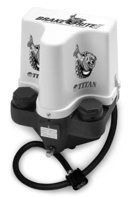
3 Thank you for purchasing a TITAN BrakeRite Actuator system. TITAN has been a pioneer in development of brake actuation and brakes. Titan s BrakeRite & BrakeRite II are state of the art ELECTRIC over HYDRAULIC BRAKE (EHB) systems. TITAN s BrakeRite systems use electric power from towing vehicle to drive hydraulic power source. In breakaway situations, electric power is supplied by a battery if trailer is completely separated from tow vehicle. This battery is charged by built in control circuitry in TITAN s BrakeRite. All BrakeRite systems are actuated one of three ways; by brake pedal of tow vehicle being depressed, manual over-ride switch on in-cab brake controller, or during breakaway situation when breakaway switch is activated. Both manual over-ride and breakaway systems are required by Federal Law. TITAN BrakeRite EHB & BrakeRite II SD systems require in-cab electric brake controller which is not provided by TITAN in these systems. These actuators will operate from most electric brake controllers WHEN PROPERLY INSTALLED. TITAN s BrakeRite II RF system has its own in-cab controller provided. WARNING -Verify wire connections are correct before energizing or powering BrakeRite system. Improper wiring can damage actuation system causing system failure. -Failure to use proper gauge wire can result in improper operation or failure of components and braking ability. For runs of wire more than twenty (20) feet, larger gauge wire should be used. -Proper grounding must be observed. Grounding to trailer frame is not acceptable. See provided diagrams for proper wiring. Proper electrical wiring is critical for performance of any BrakeRite system. Improper wiring can damage actuation system causing system failure. A pure ground and direct power (+12 VCD) with fuse or circuit breaker (30 amp) are necessary for proper performance. Adequate wire size, 12 Gauge Stranded Automotive or heavier, is required as long runs increase line loss. Line loss and poor grounding will result in poor performance or total loss of braking. Connection for BrakeRite II SD & RF systems are provided by Pre-wired harnesses and plug connectors are keyed so they cannot be connected wrong, however, if plug between tow vehicle and trailer is not wired properly, unit will not function properly, or at all. See proper wiring diagram for assistance. 1. Before each towing, perform these steps: - Check brake fluid reservoir is within 3/8 inch from filler opening of fresh, clean DOT3 or DOT4 brake fluid. Check for leaks. Service as required. - Examine actuator for wear, or other damage. Have affected components serviced. Verify actuator mounting bolts are tight. - Test actuator and brake function before transport. Failure to properly adjust brakes will result in loss of braking. 2. There are no adjustments on BrakeRite actuators. BrakeRites are shipped with tamper proof seals between cover and casting. Warranty is void if seals are broke. 3. Contact TITAN for information on where to obtain related service parts such as; breakaway switches, breakaway batteries, electrical plugs, filler caps. Page 3 of 16
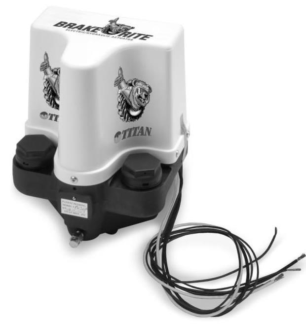
4 1) BrakeRite installation, maintenance, or repair should ONLY be performed by qualified persons who have training or knowledge of BrakeRite brake systems. 2) When installing, maintaining, or repairing TITAN equipment, wear eye protection as well as other necessary personal protective equipment. 3) TITAN equipment must be maintained in safe working order at all times. Trailer equipment should be inspected before, during, and after use for wear and damage. 4) Perform frequent and regular inspection of trailer and equipment. a. Brake Fluid Check for proper brake fluid level. Must be within 3/8 inch from filler opening. b. Breakaway Switch Verify breakaway protection is working properly. c. Breakaway Battery Confirm breakaway battery is charged properly. 5) Confirm brake actuator being used can supply enough hydraulic pressure and volume to actuate disc brakes. As a common rule, disc brakes require more pressure and larger volume of fluid than drum brakes of same size. 6) Use DOT3 or DOT4 brake fluid. Failure to use correct brake fluid may result in brake failure. 7) Be familiar with state laws in operation of towed vehicles, especially with regard to brake and braking requirements. Towing a trailer may require additional braking time and distance. Allow for this in driving habits while towing. 8) Make certain equipped trailer is safely supported at all times during installation, maintenance or repair. 9) After every hookup, test and confirm trailer brake system is operating correctly and adequately before transportation on roads. BrakeRite EHB & BrakeRite II units are similar, differences are with electronics. BrakeRite EHB has an ECB (electronic control board) built within unit and has five wires exiting. Termination of these five wires is performed by installer per wiring diagram. If not properly connected, unit will not perform properly or at all. BrakeRite II has no ECB and has a three-wire cable with Female Weather Pack plug; therefore it requires a control module. With BrakeRite II, either SD (Severe Duty) or RF (Radio Frequency) control modules are used. BrakeRite EHB & BrakeRite II use same electric motor driven piston pump and electronic controlled pressure relief valve. Exterior appearance between them is very similar, only wires exiting housing, control board, and distinct Model Markings are different. SD Control Kit for BrakeRite II is same control circuitry as BrakeRite EHB. However efforts to improve installation efficiencies and reliability SD Control kit consists of; one SD control module, one I/O harness with 7 pin RV plug 7 pin RV receptacle with three wiretap with Weather Pack plug, and one battery cable with Weather Pack plug. All electrical circuitry is plug-in, individual circuits are keyed so wires cannot be connected improperly. Great importance must be placed upon proper wiring in tow vehicle plug. RF Control Kit for BrakeRite II is designed to make BrakeRite II RF a stand-alone brake actuation system. System requires only a 4 pin flat connector between tow vehicle and trailer. Normal activation is achieved by brake/signal light circuit. Brake pressure is modulated by accelerometer output in control module. This system does not require a hard wired in-cab controller as it has its own controller. Page 4 of 16
5 RF in-cab controllers have a radio link between controller and control module. Each component has a programmable code so each controller will only communicate with intended control modules. This in-cab controller uses towing vehicles power source (cigarette lighter socket) and does not have to be hard wired into tow vehicle. Control module must be mounted facing forward and should not be totally surrounded in metal. RF Control Kit consists of; one I/O Cable, Control Module, Breakaway Switch, and Battery Cable. All cables and module leads have Weather Pack plugs to insure proper connection. Brake pressure for BrakeRite EHB & BrakeRite II SD is controlled by most in-cab electronic brake controllers. BrakeRite II RF has an in-cab controller provided. Brake performance is selected by driver. Manual override can also be applied if driver wishes to apply only trailer brakes. Federal law requires ALL trailers with brakes have ability to apply brakes in event trailer become uncoupled from tow vehicle. This requires a breakaway switch and power source (battery) on trailer. BrakeRite EHB & BrakeRite II control has circuitry for breakaway, however, breakaway switches are provided only with SD & RF control kits and no breakaway batteries is supplied with any kits. All BrakeRite models are 12 Volt DC with negative ground. Improper connections and grounding may result in system damage. For both BrakeRite EHB & BrakeRite II SD, 12 gauge or larger wire must be run from tow vehicle battery to BrakeRite with a fuse or circuit breaker for protection. Control leads for BrakeRite EHB & BrakeRite II SD and all leads for BrakeRite II RF require 16 gauge or larger wires be used. If undersized wiring is used for power leads, low voltages may occur with slow response times and poor performance of brake system. For both BrakeRite EHB & BrakeRite II SD a BREAKAWAY BATTERY OF AT LEAST 10 AMP HOURS must be used and for BrakeRite II RF AT LEAST 20 AMP HOUR BATTERY must be used. For RV applications, the house battery may be used as the breakaway battery as long as the above conditions are met at all times. Breakaway battery serves to operate both BrakeRite EHB & BrakeRite II SD as a peaking battery for applications and to supply power in a breakaway condition. While for BrakeRite II RF, battery does not only supply power for breakaway conditions but also supplies power to operate brake system. All three systems have internal chargers to maintain charge on battery from tow vehicle. Charger circuit for BrakeRite II RF requires that Running/Marker lights be on at ALL times during towing. Breakaway switch (circuit) is required by law. For standard BrakeRite EHB kits, neither switch nor batteries are included. For standard BrakeRite II kits, breakaway switch is included while batteries are not. Breakaway cables and batteries can be ordered separately if needed. When properly installed, breakaway switch applies trailer brakes in event trailer becomes un-coupled from tow vehicle. Closing of a circuit is required to activate breakaway function. Breakaway switch is normally close switch held OPEN by a plastic key. A cable is attached to key and to tow vehicle. If units become uncoupled, cable pulls key from switch closing circuit activating breakaway function and applying trailer brakes. ECB (electronic control board) has a battery protection circuit to assure breakaway (auxiliary) battery maintains a charge at all times and prevents a surge charge which could damage battery. Protection is also designed into board to prevent power draw from auxiliary battery to tow vehicles electrical system. FOLLOWING FIGURES 1-3 SHOW WIRING DIAGRAMS FOR BRAKERITE EHB, SD, AND RF. Page 5 of 16
6 Figure 1 BrakeRite EHB Wiring Diagram Figure 2 BrakeRite II SD Wiring Diagram Page 6 of 16
7 Figure 3 BrakeRite II RF Wiring Diagram Mounting location of any BrakeRite model is at discretion of installer, however accessibility for service, protection from damage, and ability to minimize length while protecting brake lines are factors to be considered. Approximate physical envelope for power unit is 6 inches front to back, 7 ¼ inches left to right, and 9 ⅛ inches high. Two sets of mounting holes are provided in power unit; one set of four located on bottom (¼-20 UNC x ⅝ deep) and one set of three located on back (5/16-18 UNC x ⅝ deep). Located on last page of this manual is a 1:1 scale drawing of power unit mounting holes. Drawing can be used as a marking and drilling diagram for custom bracketry and mounting hardware. Verify scale before use. All BrakeRites have a ⅛-27 NPTF port located on lower front of housing and a straight ⅛-27 NPTF Male by #3 Female Inverted Tube seat (¾-24 NPTF) adapter. When installing any adapter, DO NOT USE TEFLON PIPE TAPE as properly mated brass fitting joints DO NOT require a sealant. Route brake lines to axles per Brake Line Fitting Kit manufacturer s instructions. Use flexible tubing as required and secure all tubing for maximum protection from pinching, vibration, corrosion, or road hazards. When bending and flaring steel tubing, always use proper tools to assure sound connections and prevent kinked lines. Kinked and/or damaged brake lines can cause restriction in flow resulting in poor braking or no brakes at all. Page 7 of 16
8 Depending on brake system chosen, there are various approaches to be considered for electrical connections. Though TITAN produces BrakeRite systems, TITAN has NO control over how towing vehicle or trailer has been wired or its color coding. Therefore, when installing any BrakeRite system, it is important that all wiring is connected per these instructions. While it is desirable to establish a ground between frame, BrakeRite unit, and negative side of breakaway battery, NEVER RELY SOLELY ON FRAME GROUNDING. Always use good ground leads between ALL specified points. If rewiring from electric brakes, start wiring as close to front of trailer as possible. A junction box, pin box, or 7-way plug, are preferred starting locations. As electrical portion of installation is carried out, make certain wires are properly routed, wrapped, anchored, and protected to prevent damage, catching on road hazards, or rubbing on frame components. When making connections in circuits, other than plug-in connectors, desirable joint is a solder joint. If using crimp-type joints, always use manufacturers recommended crimping tools in accordance with manufacturer s directions and always properly wrap and protect all joints to prevent shorting and corrosion. Heat shrinking joints also help prevent water causing shorts or corrosion. BrakeRite EHB requires installer assure all wire are connected properly. See wiring diagram Figure 1 on page 6 for preferred method for electrical wiring. This method requires an independent battery solely for brake system. However, towed vehicle auxiliary batter can be used in place of breakaway battery if it is in good condition and fully charged. NOTE: If trailer has set for an extended period of time, auxiliary battery may have been discharged excessively resulting in poor or no braking. If system is being converted from electric brakes, remove as much old brake wiring as possible and run new wires. This will ensure wires used are of adequate size and give better operation of BrakeRite. Function and size of five (5) wires exiting BrakeRite EBH are as follows: White: 12 gauge, 12 VDC negative (-) system ground Black: 12 gauge, 12 VDC positive (+) system power in Blue: 16 gauge, Brake Control Input (from in cab electronic brake controller) Brown: 16 gauge, Breakaway Input (from one lead of breakaway switch) Violet (Mauve): 14 gauge, 12 VDC Input/Output between Unit and Breakaway battery. (2 nd lead of breakaway switch is also connected to 12 VDC positive of breakaway battery) BrakeRite II SD kits have a complete wiring harness as a plug-in system and all connections within have been preselected so that upon installation connections are simply plugged in. It is crucial that SEVEN PIN RV receptacle on tow vehicle is wired per Figure 4. Two basic options left are whether to use an auxiliary battery on trailer, if one is available, or to install a separate breakaway battery (preferred). No battery is supplied with standard kits. Figure 2 on page 6 illustrates preferred method (separate breakaway battery) however; trailer auxiliary battery can be used in place of breakaway battery if it is in good condition, fully charged, and Figure 4 Most Common Factory Installed Wiring Arrangement Page 8 of 16

9 BrakeRite II RF kits are supplied complete with wiring harness as a plug-in system so all connection within have been pre-selected from factory. Four Pin Flat Connector on tow vehicle must be wired as shown in Figure 5. Similar to SD kit, options that are left is whether to use an auxiliary battery on trailer, if one is available or to install a separate breakaway battery (preferred). No battery is supplied with standard kit. Figure 3 on page 7 illustrates preferred method (separate breakaway battery) however; trailer auxiliary battery can be used in place of breakaway battery if it is in good condition, fully charged, and meets amperage requirements. After unit has been mounted, brake lines installed, and electrical connection completed, system start-up can begin. Remove one filler cap and fill reservoir to within ⅜ inch of filler cap opening. (Either cap can be used as both fill same reservoir) Fill reservoir with NEW DOT3 or DOT4 BRAKE FLUID. Never reuse brake fluid that has been salvaged or removed from another system. Contaminated brake fluid may cause damage resulting in system failure. Figure 5 Industry Standard Four Pin Flat Configuration All air must be removed from brakes and brake lines prior to trailer operation. To bleed brakes, remove key from breakaway switch to start unit. Starting with brake furthest from actuator, open bleeder screw and allow it to remain open until brake fluid releases free of air bubbles. Close bleeder screw and move to next brake closer to BrakeRite until all brakes have been bled. While performing bleeding process, monitor fluid level in reservoir so air is not pumped into brake lines because of low fluid. Running BrakeRite pump dry can also cause damage to motor. To prevent spilling brake fluid on ground, place one end of length of plastic tubing over end of bleeder screw and other end should be placed into a container so that fluid flow can be monitored for bubbles. After all brakes have been bled, replace key in breakaway switch. WARNING -Use fresh DOT3 or DOT4 brake fluid from sealed container. DO NOT reuse brake fluid. Failure to use fresh brake fluid increases chance of brake failure. -Use care when handling brake fluid. DO NOT allow brake fluid to contact painted surfaces. It will damage surface finishes. Wipe up spills immediately and wash area with water. -This is a high pressure system. ALL air must be removed. Any air in brake lines will cause brakes not to function properly. Bleed brake system completely. Page 9 of 16
10 When coupling trailer to tow vehicle always assure that two vehicles are coupled in accordance with vehicle manufactures instructions and that all coupling devices and procedures conform to applicable state and federal regulations. After units are properly coupled, connect electrical plug. Assure that safety cable from breakaway switch on trailer is connected to tow vehicle. To assure proper connections have been made, most in-cab controllers have some type of indicator showing electrical connections are adequate. Consult in-cab controller manufacturers operator s manual for proper checking and setting procedures. Before moving vehicle depress tow vehicle brake pedal, BrakeRite unit should start (audibly hear unit). Release tow vehicle brake pedal and activate BrakeRite unit by operating manual override on in-cab controller. Again, unit will be heard running. With manual override, a tone change will occur as pressure builds relative to activation amount initiated from override switch. Do not attempt to move unit or trailer until brake system performs properly in described tests above. After system responds to tests previously described, proceed with moving vehicle to establish feel for brake system and also to calibrate brake response based upon instructions given in brake controller manual. This adjustment should be performed in a parking lot or low traffic area. Do not attempt to operate unit in congested traffic or on major though fares until familiarized with feel and performance of brake system. Every operator and every vehicle have unique requirements and characteristics. Take time to be familiar with how unit feels, performance, and proper operation and setting selections of brake controller. Trailer brakes are meant to assist tow vehicle in stopping of combined units and are not intended to stop entire combined unit. Two basic types of In-Cab Electronic Brake Controllers exist. Inertia based controllers create a small bias braking force when activated and modulates braking forces of trailer relative to braking reaction created by tow vehicle. Inertia controllers offer most desirable braking effect. Another type is time based controllers. Time based controllers turn on when tow vehicle s brake pedal is applied and braking for increases at a selected rate until it reaches a maximum set point. This does not produce as smooth of braking as inertia based controllers and is very speed sensitive. No matter type of controller used, thoroughly know controllers performance and feel before extensive travel is considered. Manual override is required by law and should be fully understood for proper and safe operation. This allows trailer brakes to be activated without depressing tow vehicles brake pedal. Page 10 of 16
11 Periodic inspection of electrical connectors, wiring, brake lines, and hose for entire brake system to insure no abraded or bare wires, damaged steel lines, or cracked and damaged hoses exist. During inspection assure there are no loose or hanging lines or wire that might drag or catch on object/debris during transport. EVERY time trailer is coupled to tow vehicle, check following items: 1. Check fluid level in reservoir. Fluid level must be maintained within 3/8 below filler opening. If brake fluid is required, add only new, clean DOT3 or DOT4 brake fluid. Use caution when removing reservoir cap to prevent admission of any contaminants into fluid reservoir. 2. Check breakaway battery is charged and breakaway system works. Test by pulling cable on breakaway switch. If vehicle has been parked for long periods, breakaway battery may be discharged. If this situation occurs, charge battery per manufacturers recommendations prior to using trailer. If battery is discharged in cold environments, freezing battery, damage may have occurred to battery. 3. Inspect coupler and safety chains to assure they are fully functional and for wear or damage. All equipment must meet manufacturer s specifications and recommendations and all applicable state and federal laws. BrakeRite EHB, BrakeRite II SD, and BrakeRite II RF are shipped from factory with tamper proof seals between cover and casting. Warranty is void if these seals have been broken. Contact TITAN Distribution, Inc. at 800-USA- BEAR ( ) for information where to obtain related service parts such as; breakaway switches, breakaway batteries, electrical plugs, and filler caps. Experience has shown that virtually all problems with BrakeRite unit are results of INCORRECT or FAILED WIRING. If problems arise, consult applicable wiring diagram (Pg. 6-7) and inspect all wiring and terminations. A bench test can be performed as follows. Connect Black wire to positive (+) and White to negative (-) power source. Proceed to momentarily tap Blue wire to positive (+) side of power source. Motor should switch on briefly. Next momentarily tap Brown wire to positive (+) side of power source. Motor should switch on briefly. If both tests work, problems are not in BrakeRite unit. Wiring and other components should be checked for problems. ISSUE Indicator on In Cab Controller shows no connection between tow vehicle and trailer Poor response time Inadequate or excessive trailer braking BrakeRite unit runs but does not build pressure BrakeRite unit does not run when breakaway is pulled BrakeRite unit does not run when vehicle brake pedal is depressed BrakeRite unit does not run when in-cab manual override is activated SOLUTION Inspect plug and wiring for open circuit. Consult applicable wiring diagram for proper connections Check and add brake fluid as required Bleed brake lines and devices Check input for adequate Charge (12 VDC) Adjust gain control on In-Cab Controller Assure proper brake fluid level, add fluid and bleed system as required Check breakaway battery charge and assure wires are properly connected Verify and connect wire connections in entire electrical circuit. Verify and connect wire connections in entire electrical circuit. Page 11 of 16
12 Page 12 of 16
13 Page 13 of 16
14 PAGE INTENTIONALLY LEFT BLANK Page 14 of 16
15 PAGE INTENTIONALLY LEFT BLANK Page 15 of 16
16 LIMITED WARRANTY Limited Warranty Titan Tire Corporation (TITAN) warrants its products to be free from defects in material and workmanship for 18 months from date of installation with proof of purchase, or 18 months from date of manufacture if proof cannot be presented. Warranty is valid if unit has only been used on vehicle which it was first installed by the original purchaser and has been properly installed, used, and maintained by the purchaser. This warranty does not apply to damage or loss caused by any or all of the following circumstances or conditions: Freight damage. Parts, accessories, materials or components not obtained former approved in writing by TITAN. Misapplication, misuse and failure to follow the directions or observe cautions and warnings on installation, operation, application, inspection or maintenance specified in any TITAN quotations, acknowledgements, sales literature, specification sheet or installation instructions and service manual ( applicable literature ) If any TITAN products are found upon TITAN s examination to have been defective when supplied, TITAN will either: credit the purchaser s account for the purchase price of the TITAN product; or repair the product. TITAN has sole discretion in choosing which option to provide. For this LIMITED WARRANTY to apply, TITAN must receive notice of the alleged defect within 30 days of either the discovery of the alleged defect or the expiration of the warranty period, whichever is earlier. Any claim not made within this period shall conclusively be deemed waived. If requested by TITAN, purchaser shall return the alleged defective product to TITAN for examination at TITANS s direction and expense. TITAN will not pay for expenses incurred in returning a product to TITAN without TITAN s prior written authority. TITAN shall not be liable for any other expenses purchaser incurs to remedy any defect. Purchasers waive subrogation on all claims under any insurance. Limitation of Liability It is expressly agreed that the liability of TITAN is limited and TITAN does not function as an insurer. THE REMEDIES SET FORTH IN THIS WARRANTY SHALL CONSTITUE THE EXCLUSIVE REMEDIES AVAILABLE TO THE PRUCHASER OR USER AND ARE IN LIEU OF ALL OTHER REMEDIES, EXPRESS OR IMPLIED. THE LIABILITY OF TITAN, WHEATHER IN CONTRACT, IN TORT, UNDER ANY WARRANTY OR OTHERWISE, SHALL NOT EXCEED THE PURCHASE PRICE OF THE PARTICULAR PRODUCT MANUFACTURED, SOLD OR SUPPLIED BY TITAN. To Obtain Technical Assistance To enable TITAN to respond to a request for assistance or evaluation of customer or user operation difficulty, please provide at a minimum the following information by calling or within Iowa : Model number, serial number and all other data on the specific component which appears to be involved in the difficulty. The date and from whom you purchased your TITAN product. State your difficulty, being sure to mention at least the following: Application, Nature of load involved, and Weight of the load. TITAN EXTENDS NO WARRANTY, EXPRESS OR IMPLIED, ON PRODUCTS NOT MANUFACTURED BY TITAN OR TO TITAN S DESIGN SPECIFICATION, INCLUDING BUT NOT LIMITED TO SUCH ITEMS AS NON-TITAN TIRES, BRAKES, ACTUATORS, BEARINGS, HOSE AND TUBING, PURCHASER S RECOURSE SHALL BE LIMITED TO ANY WARRANTY OF THE PERSPECTIVE MANUFACTURERS. THIS WARRANTY EXCLUDES ALL IMPLIED WARRANTIES OF MERCHANTABILITY OR FITNESS FOR A PARTICULAR PURPOSE OR ANY PURPOSE. THIS WARRANTY DOES NOT COVER NOR EXTEND TO INCIDENTAL OR CONSEQUENTIAL DAMAGE. Some states do not allow the exclusion or limitation of incidental or consequential damages, so the above limitation or exclusion may not apply to you. No representative has authority to make any representation, promise or agreement except as stated in this Limited Warranty. TITAN reserves the right to make design and other changes upon its products without any obligation to install the same on any previously sold or delivered products. THERE ARE NO WARRANTIES WHICH EXTEND BEYOND THOSE DESCRIBED ABOVE. EFFECTIVE JANUARY 1, 1998 THIS WARRANTY SUPERSEDEDS ALL PRIOR WARRANTIES, WIRTTEN OR IMPLIED. Page 16 of 16
INSTALLATION, INSTRUCTION AND SERVICE MANUAL
 INSTALLATION, INSTRUCTION AND SERVICE MANUAL Actuator/Brake/Trailer Dealer Please provide to consumer. Consumer Read and follow instructions. Keep with trailer for reference. Page 1 of 7 1. Introduction...
TITAN 13 x 2½ BRAKES DUO-SERVO AND FREE BACKING
 INSTALLATION INSTRUCTION AND SERVICE MANUAL Actuator/Trailer Dealer - Please provide these instructions to the consumer. Consumer - Read and follow these instructions. Keep them with the trailer for future
INSTALLATION INSTRUCTIONS
 INSTALLATION INSTRUCTION AND SERVICE MANUAL Actuator/Trailer Dealer - Please provide these instructions to the consumer. Consumer - Read and follow these instructions. Keep them with the trailer for future
PREMIER, MARINE, & STANDARD
 INSTA LLATION INSTRUCTION AND SERVICE MANUAL I TITAN 12" x 2" BRAKES FREE BACKING. UNI-SERVO. DUO-SERVO PREMIER, MARINE, & STANDARD Limited Warranty TITAN Inc. ("TITAN') warrants its products to be free
Installation Instructions and Service Manual
 Installation Instructions and Service Manual Model 80 Actuator* for Trailer Brakes 8,00 lbs Capacity Drum Brake Ready Disc Brake Ready US Patents: 6,37,2 and 8,342,9 *Model 80 - Manufactured after March
Installation Instructions and Service Manual
 Installation Instructions and Service Manual Model 700LP/750LP (Low Profile) Actuator* for Trailer Brakes 7,000/7,500 lbs. Capacity Drum Brake Ready/Disc Brake Ready *US Patent No. 6,375,211 MODEL 700LP/750LP
Installation Instructions and Service Manual
 Installation Instructions and Service Manual Model 66 Actuator* for Trailer Brakes 6600 lbs Capacity Part #47210/86167 - Drum Brake Ready Part #47211/86165 - Disc Brake Ready *US Patent No. 6,375,211 MODEL
TITAN MODEL 6 SURG-O-MATIC ACTUATOR FOR TRAILER BRAKES
 INSTALLATION INSTRUCTION AND SERVICE MANUAL Actuator/Trailer Dealer - Please provide these instructions to the consumer. Consumer - Read and follow these instructions. Keep them with the trailer for future
Model 66/660* Actuator for Trailer Brakes 6,600 lbs Capacity Drum Brake Ready or Disc Brake Ready US Patent No. 6,375,211
 Installation Instructions and Service Manual Model 66/660* Actuator for Trailer Brakes 6,600 lbs Capacity Drum Brake Ready or Disc Brake Ready US Patent No. 6,375,211 *Model 660 - Manufactured after March
Model 80 & 80E Actuator* for Trailer Brakes 8000 lbs Capacity Part #47206/ Drum Brake Ready Part #47208/ Disc Brake Ready
 Installation Instructions and Service Manual For Serial Numbers 6020 and above. Model 80 & 80E Actuator* for Trailer Brakes 8000 lbs Capacity Part #47206/47207 - Drum Brake Ready Part #47208/47209 - Disc
MANUAL SERVICE MANUAL FOR HYDRASTAR HYDRAULIC TRAILER BRAKE ACTUATORS
 MANUAL 440-1008 SERVICE MANUAL FOR HYDRASTAR HYDRAULIC TRAILER BRAKE ACTUATORS THIS DOCUMENT TO BE USED FOR HBA-10, HBA-12, HBA-16, MHBA-10, MHBA-12, MHBA-16 ACTUATORS ECN 04007 Manual 440-1008 Rev E Page
Model 660E Brake Actuator Owner s Manual
 Model 660E Brake Actuator Owner s Manual Installation Instructions and Service Manual Model 660E Actuator for Trailer Brakes 6,600 lbs. Capacity Drum or Disc Brakes Table of Contents Page Actuator Installation
ActuLink ABS Module - ABS-MOD-400
 Installation Instructions ActuLink ABS Module - ABS-MOD-400 For more information on the installation and operation of Tuson s towable ABS system, consult the installation and operations manuals for the
TITAN MODEL 60 SURG-O-MATIC ACTUATOR FOR TRAILER BRAKES
 INSTALLATION INSTRUCTION AND SERVICE MANUAL Actuator/Trailer Dealer - Please provide these instructions to the consumer. Consumer - Read and follow these instructions. Keep them with the trailer for future
TITAN MODEL 20 SURG-O-MATIC ACTUATOR FOR TRAILER BRAKES , , , INTRODUCTION TO SURGE BRAKING
 INSTALLATION INSTRUCTION AND SERVICE MANUAL Actuator/Trailer Dealer - Please provide these instructions to the consumer. Consumer - Read and follow these instructions. Keep them with the trailer for future
TITAN AERO 7500 ACTUATOR FOR TRAILER BRAKES INTRODUCTION TO SURGE BRAKING
 INSTALLATION INSTRUCTION AND SERVICE MANUAL Actuator/Trailer Dealer - Please provide these instructions to the consumer. Consumer - Read and follow these instructions. Keep them with the trailer for future
12 Volt Utility Controller for 4, 6, or 8 Brakes No
 12 Volt Utility Controller for 4, 6, or 8 Brakes No. 1300-76 P-1396-WE 819-0301 Installation Instructions An Altra Industrial Motion Company Contents Introduction... 2 Installation... 3 Mounting Under
Installation of Hydraulic Disc Brake System with the ActiBrake Actuator Sand Drive Fort Worth, Texas
 Installation of Hydraulic Disc Brake System with the ActiBrake Actuator 7600 Sand Drive Fort Worth, Texas 76118 800-756-3425 The Integrated Hydraulic Brake System page 1 ActiBrake - Part of a System ActiBrake
Utility Controller Hand Air Operated
 Utility Controller Hand Air Operated P-1395 819-0288 Installation Instructions Introduction The Warner Electric air/manual Utility Controller combines manual and automatic (air) actuation for the operation
Dodge Ram 5.9L Cummins LOW FUEL PRESSURE ALARM LIGHT - Installation Manual -
 29 September 2005 Dodge Cummins Low Fuel Pressure Alarm Light Kit 1081130-33 1 1999-2005 Dodge Ram 5.9L Cummins LOW FUEL PRESSURE ALARM LIGHT - Installation Manual - Part Number Sequence: 1081130 Red 1081133
V-Twin Forward Control Installation Instructions
 V-Twin Forward Control Installation Instructions Thank you for a choosing a Supreme Legends USA product. Supreme Legends forward controls are designed to add style and performance to your bike. Our extended
SOLAR DASH CHARGING SYSTEM USER GUIDE
 SOLAR DASH CHARGING SYSTEM Doc 1.01 INST049 INSTALLATION STEP 1 Place 20 watt solar panel in the dash of the vehicle facing up. Note: For ideal results position the vehicle in a manner in which the solar
½ DODGE CUMMINS OEM BYPASS LIFT PUMP KIT Installation Instructions Part #
 29 July 2005 2003-04.5 Dodge Cummins OEM Bypass Lift Pump Kit # 1050227-1 - 2003-04½ DODGE CUMMINS OEM BYPASS LIFT PUMP KIT Installation Instructions Part # 1050227 PLEASE READ ALL INSTRUCTIONS CAREFULLY
11202 INSTALLATION INSTRUCTIONS
 11202 INSTALLATION INSTRUCTIONS WARNING! The fuel system may be under pressure. Do not open the fuel system until any pressure has been relieved. The enclosed Aeromotive fuel pump utilizes an o-ring sealed
SELECT -24 INSTALLATION GUIDE. INST036 Doc 2.02
 SELECT -24 INSTALLATION GUIDE INST036 Doc 2.02 CONTENTS General Information...2 Select-24 Diagram...3 Mounting the Select Controller...4 Dual Pole Nosebox Installation...5 Aux Harness Installation...6
12 Volt Utility Controller for 4, 6 or 8 Brakes No P
 12 Volt Utility Controller for 4, 6 or 8 Brakes No. 1300-77 P-1379 819-0094 Installation Instructions Introduction The Warner Electric manually operated Utility Controller operates 4, 6, or 8 twelve-volt
DODGE CUMMINS Arctic-Heat Grid Relocation Kit
 Installation Manual P/N 07509-350-GRK 2007.5-09 DODGE CUMMINS Arctic-Heat Grid Relocation Kit Installation Instructions P/N 07509-350-GRK GDP Arctic-Heat Grid Heater Installation PLEASE READ ALL INSTRUCTIONS
INSTALLATION GUIDE. Universal System for Zero Turn Mowers
 INSTALLATION GUIDE Universal System for Zero Turn Mowers Table of Contents General Information 1 Important Notice to Purchaser 2 Specifications 2 Intended Usage 2 Important Information 3 General Safety
Safety Sentry Electronic Breakaway Switch
 Safety Sentry Electronic Breakaway Switch P-616-WE 819-0454 Installation Instructions An Altra Industrial Motion Company Parts List Mounting hardware included with the Safety Sentry Breakaway Switch kit:
AEROMOTIVE Part # L Mustang Digital FMU INSTALLATION INSTRUCTIONS
 AEROMOTIVE Part # 17113 4.6L Mustang Digital FMU INSTALLATION INSTRUCTIONS CAUTION: Installation of this product requires detailed knowledge of automotive systems and repair procedures. We recommend that
PVI 1800/PVI Residential/Commercial Grid-Tied Photovoltaic Inverter WARRANTY MANUAL. Subject to Change REV , Solectria Renewables
 PVI 1800/PVI 2500 WARRANTY MANUAL Residential/Commercial Grid-Tied Photovoltaic Inverter 2009, Solectria Renewables Subject to Change REV 10.09 1 Product Warranty & RMA Policy 1.1 Warranty Policy The Solectria
DODGE CUMMINS 24V ISB OEM BYPASS LIFT PUMP KIT Installation Instructions Part #
 2/15/2006 2000-2002 Dodge Cummins OEM Bypass Lift Pump Kit # 1050229-1 - 2000-02 DODGE CUMMINS 24V ISB OEM BYPASS LIFT PUMP KIT Installation Instructions Part # 1050229 PLEASE READ ALL INSTRUCTIONS CAREFULLY
Installation and Operation Instructions Safety Director Arrow
 Installation and Operation Instructions Safety Director Arrow! WARNING! Failure to install or use this product according to manufacturers recommendations may result in property damage, serious bodily/personal
SELECT DIAGNOSTIC GUIDE. INST028 Doc 3.02
 SELECT DIAGNOSTIC GUIDE INST028 Doc 3.02 CONTENTS General Information...2 Select Call-Outs...3 Wire Diagram and Legend...4 Diagnostics...6 Excessive Voltage Drop Diagnostics...6 Static Diagnostics...7
Model A Turn Signal Kit Installation Guide
 Model A Turn Signal Kit Installation Guide Creative Connections, Inc. Consumer Hot Line: 888-471-LOGO 770-476-7322 In Atlanta, GA http://www.logolites.com P/N: 100-005/K 2008 Creative Connections, Inc.
HOW TO INSTALL YOUR BOV
 Product Name: Product Description: Product Number: BMW Kompact BOV Kit Model specific BOV Kit TS-0203-1050/TS-0203-1250 ------------------------------------------------------------------------------------------------------------------------
INSTALLATION AND MAINTENANCE MANUAL FORM #PM-126 REV A 12/09
 HAND CRANK & MOTORIZED POWER CORD REELS: SERIES 1125PC SERIES: 1125PC HAND CRANK SERIES: 1125PC MOTORIZED COXREELS The technical data and images which appear in this manual are for informational purposes
REDI-LINE. Rugged, Reliable, DC to AC Power Conversion ELECTRIC GENERATORS USER'S GUIDE. KARAM A.L.
 REDI-LINE ELECTRIC GENERATORS USER'S GUIDE Rugged, Reliable, DC to AC Power Conversion KARAM A.L. www.alternatorstarter.com 1-888-515-2726 REDI-LINE ELECTRIC GENERATOR MODEL INPUT ACTUAL OUTPUT ACTUAL
CLASSIC II Portable Braking System
 39495 CLASSIC II Portable Braking System Inventor and Leader in Portable Technology! INSTRUCTIONS NEED HELP? CALL - 1-800-470-2287 (MONDAY - FRIDAY 8AM - 5PM CST) WARNING Read all instructions before installing
WARNINGS, CAUTIONS AND NOTES
 Welcome Please read this manual thoroughly before installing and operating your new Power Bright Power Inverter. This manual contains information you need to obtain the performance required for your application.
AEROMOTIVE Part # Mustang 5.0L Fuel System Kit INSTALLATION INSTRUCTIONS
 AEROMOTIVE Part # 17103 83-93 Mustang 5.0L Fuel System Kit INSTALLATION INSTRUCTIONS CAUTION: Installation of this product requires detailed knowledge of automotive systems and repair procedures. We recommend
II DISTRIBUTION & SUBSTATION TYPE C
 CapCheckIII DISTRIBUTION & SUBSTATION TYPE Ca p a c i t o r C h e c ke r Operating & Instruction Manual 1475 Lakeside Drive Waukegan, Illinois 60085 U.S.A. 847.473.4980 f a x 8 4 7. 4 7 3. 4 9 8 1 w e
TRAILER AUXILIARY POWER SYSTEM (TAPS) INSTALLATION GUIDE V1.10
 INSTALLATION GUIDE V1.10") TRAILER AUXILIARY POWER SYSTEM (TAPS) INSTALLATION GUIDE V1.10 TAPS INSTALLATION GUIDE V1.10 1 TRAILER AUXILIARY POWER SYSTEM CONTENTS General Information and System Logic... 2 Diagrams... 3 System Diagram
TRAILER AUXILIARY POWER SYSTEM (TAPS) INSTALLATION GUIDE V1.10 TAPS INSTALLATION GUIDE V1.10 1 TRAILER AUXILIARY POWER SYSTEM CONTENTS General Information and System Logic... 2 Diagrams... 3 System Diagram
Power. On Your Terms.
 Power. On Your Terms. 10 YEAR LIMITED WARRANTY PHI 1310 TM 1 SIMPLIPHI POWER, INC. REV102016 10 YEAR LIMITED WARRANTY: PHI 1310 TM LIMITED PRO-RATED WARRANTY COVERAGE The SimpliPhi Power PHI 1310 as supplied
Installation Power Management Unit Battery Cables and Battery Harness
 Installation Power Management Unit Battery Cables and Battery Harness Important Safety Messages SAVE THESE INSTRUCTIONS - This manual contains important instructions that should be followed during installation
18318 INSTALLATION INSTRUCTIONS CHEVROLET IMPALA
 18318 INSTALLATION INSTRUCTIONS 65-66 CHEVROLET IMPALA The enclosed Aeromotive fuel tank/pump assembly utilizes an o-ring sealed AN-06 style feed, return and vent ports. These ports seal with o-rings;
10 Year Limited Warranty
 Power. On Your Terms. 10 Year Limited Warranty PHI 2.7 TM PHI 3.5 TM 60A SIMPLIPHI POWER, INC. REV020618 10 Year Limited Warranty: PHI 2.7 TM PHI 3.5 TM 60A 24V 48V Limited Pro-Rated Warranty Coverage
AEROMOTIVE Part # L Ford F L Ford Expedition L Ford F-250 Super Duty INSTALLATION INSTRUCTIONS
 AEROMOTIVE Part # 14118 97-03 5.4L Ford F-150 97-02 5.4L Ford Expedition 98-03 5.4L Ford F-250 Super Duty INSTALLATION INSTRUCTIONS CAUTION: Installation of this product requires detailed knowledge of
A/C PRESSURE MONITOR INSTALLATION INSTRUCTIONS SYSTEM OPERATION GREEN INDICATOR LIGHT
 A/C PRESSURE MONITOR INSTALLATION INSTRUCTIONS Do not attempt to clean or inspect anything while the engine is running. Cleaning and inspection must be done by a certified mechanic. All A/C service must
OWNERS MANUAL JANUARY 2007 ISO
 Manufacturer of Dimensions TM Inverters 4467 White Bear Parkway St. Paul, MN 55110 Phone: 651-653-7000 Fax: 651-653-7600 E-mail: inverterinfo@sensata.com Web: www.dimensions.sensata.com 121231B OWNERS
AEROMOTIVE Part # Street Rod Fuel Pump System INSTALLATION INSTRUCTIONS
 AEROMOTIVE Part # 17201 Street Rod Fuel Pump System INSTALLATION INSTRUCTIONS CAUTION: Installation of this product requires detailed knowledge of automotive systems and repair procedures. We recommend
Installation & Operators Manual
 Installation & Operators Manual Model Serial Number Purchase Date 2007-2008 SegVator, LLC Patent Pending All Rights Reserved Important Safety Information Make sure the vehicle has a properly installed
ACTUATORS. Titan Moves the World
 VOLUME 1 ACTUATORS Titan Moves the World Shaded part # s ending in 10 have solenoid covers only. Shaded part # s ending in 20 have solenoids and covers. Unshaded part numbers do not have solenoids or covers.
AEROMOTIVE Part # and F-Body Fuel System Kit INSTALLATION INSTRUCTIONS
 AEROMOTIVE Part # 17101 and 17102 93-97 F-Body Fuel System Kit INSTALLATION INSTRUCTIONS CAUTION: Installation of this product requires detailed knowledge of automotive systems and repair procedures. We
7.3L POWERSTROKE BANJO BOLT KIT Fits L Powerstroke Diesel. Installation Guide
 7.3L POWERSTROKE BANJO BOLT KIT Fits 94-03 7.3L Powerstroke Diesel Installation Guide INSPECT CONTENTS OF THIS KIT THOROUGHLY BEFORE STARTING THE INSTALLATION PROCESS! IF YOU FIND A PROBLEM WITH YOUR PACKAGE:
Telescopic Transmission Jacks
 Telescopic Transmission Jacks Operating Instructions & Parts Manual Model Number BH7051 BH7055 (Air/Manual) Capacity 1/2 Ton 1/2 Ton SFA Companies 2006 10939 N. Pomona Ave. Kansas City, MO 64153 816-891-6390
ADI-125/750 ADI-125/1500 ADI-125/2500
 Manufacturer of Dimensions TM Inverters 4467 White Bear Parkway St. Paul, MN 55110 Phone: 651-653-7000 Fax: 651-653-7600 E-mail: inverterinfo@sensata.com Web: www.dimensions.sensata.com 121094B OWNERS
DC to AC Power Inverters
 Manufacturer of Dimensions TM Inverters 4467 White Bear Parkway St. Paul, MN 55110 Phone: 651-653-7000 Fax: 651-653-7600 E-mail: inverterinfo@sensata.com Web: www.dimensions.sensata.com ISO 9001:2000 Certified
AEROMOTIVE Part # L Ford F L Ford Expedition L Ford F-250 Super Duty INSTALLATION INSTRUCTIONS
 AEROMOTIVE Part # 14118 97-03 5.4L Ford F-150 97-02 5.4L Ford Expedition 98-03 5.4L Ford F-250 Super Duty INSTALLATION INSTRUCTIONS CAUTION: Installation of this product requires detailed knowledge of
TALCO FIRE SYSTEMS. LSF Start-Up Instructions. 1) IMPORTANT: Inspect the unit for damage. Report any damage to the freight carrier immediately.
 IMPORTANT: Inspect the unit for damage. Report any damage to the freight carrier immediately.") LSF Start-Up Instructions 1) IMPORTANT: Inspect the unit for damage. Report any damage to the freight carrier immediately. 2) PRE-START-UP: Be sure there is water in the pump. Bleed air at all high points
LSF Start-Up Instructions 1) IMPORTANT: Inspect the unit for damage. Report any damage to the freight carrier immediately. 2) PRE-START-UP: Be sure there is water in the pump. Bleed air at all high points
SOLAR BOLT CHARGING SYSTEM INSTALLATION GUIDE
 CHARGING SYSTEM Doc 1.00 INST052 1 SOLAR BOLT CHARGING SYSTEM CONTENTS General Information... 2 Solar Panel Installation... 3 Solar Bolt Main Harness and Indicate Installation... 4 Cable Routing... 9 Solar
Select II Portable Braking System
 39523 Select II Portable Braking System Inventor and Leader in Portable Technology! INSTRUCTIONS NEED HELP? CALL - 1-800-470-2287 (MONDAY - FRIDAY 8AM - 5PM CST) WARNING Read all instructions before installing
Air Curtain. Installation, Operating and Maintenance Instructions
 Installation, Operating and Maintenance Instructions Save this manual for future reference. Air Curtain Model Numbers: ES026, ES036, ES042, ES048, ES060, ES072 READ THIS OWNER S MANUAL CAREFULLY BEFORE
GORE TRAILER MANUFACTURING INCORPORATED 305 Gore Trailer Road Whiteville, North Carolina 28472
 (Revised September, 2005) GORE TRAILER MANUFACTURING INCORPORATED 305 Gore Trailer Road Whiteville, North Carolina 28472 WARRANTY TEN YEAR WARRANTY Subject to the requirements, exclusions and limitations
INSTALLATION MANUAL DURAMAX DIESEL POWERED PICKUP TRUCKS MODEL RP-100 & RP-150. With New Quick Connect Components!
 INSTALLATION MANUAL 2001-2009 DURAMAX DIESEL POWERED PICKUP TRUCKS MODEL RP-100 & RP-150 With New Quick Connect Components! PLEASE READ THESE INSTRUCTIONS THOROUGHLY BEFORE BEGINNING INSTALLATION! 705
HBC-20 - LED HIGH BAY
 To prevent death, injury or damage to property, this product must be installed in accordance to National Electrical Code (NFPA70) in the US or Canadian Electrical Code (CSA.) in Canada. Risk of fire or
DIRECT PLUS/FLEX/MAX INSTALLATION GUIDE. INST165 Doc 1.04
 DIRECT PLUS/FLEX/MAX INSTALLATION GUIDE INST165 Doc 1.04 CONTENTS General Information...2 Diagrams...3 Mounting the Direct Nosebox...5 Main Harness Installation...6 Interior Light Harness Installation...10
CAPACITOR ACTUATED PORTABLE STARTER CAPS USER GUIDE. INST048 Doc 3.01
 CAPACITOR ACTUATED PORTABLE STARTER CAPS USER GUIDE INST048 Doc 3.01 CONTENTS General Information...2 Charts...3 Before First Use...4 Safety Requirements...5 What to Expect from the CAPS...5 CAPS Diagram...6
AEROMOTIVE Part # A2000 Fuel Pump Kit INSTALLATION INSTRUCTIONS
 AEROMOTIVE Part # 17202 A2000 Fuel Pump Kit INSTALLATION INSTRUCTIONS CAUTION: Installation of this product requires detailed knowledge of automotive systems and repair procedures. We recommend that this
PVI 60KW, PVI 82KW, PVI 95KW
 PVI 60KW PVI 82KW PVI 95KW WARRANTY MANUAL Commercial, Grid-Tied Photovoltaic Inverters 2008, Solectria Renewables LLC Subject to Change DOC-020099 rev 024 1 1 Product Warranty & RMA Policy Warranty Policy
OWNER S MANUAL EVOLUTION 3500, 4500, 5500, & 8500 SERIES PUMPS
 OWNER S MANUAL EVOLUTION 3500, 4500, 5500, & 8500 SERIES PUMPS IMPORTANT SAFETY INSTRUCTIONS When installing and using this electrical equipment, basic safety precautions should always be followed, including
INVERTER HARNESS INSTALLATION FOR FREIGHTLINER CASCADIA
 FOR FREIGHTLINER CASCADIA Part #: P808 1004FC 08/05/2014 Doc 1.04 INST065 Page 1 Step 1: Unpack the plate assembly and both positive and negative cables. INSTALLATION INSTRUCTIONS Step 2: Insert the negative
 Product Name: Product Description: Product Number: Comp-Gate40 40mm External TS-0505-1XXX ------------------------------------------------------------------------------------------------------------------------
END USER TERMS OF USE
 END USER TERMS OF USE The following is the End Users Terms of Use as it currently appears in the Mobileye User Manual and Warranty information. This is here for your review and information; it is subject
AEROMOTIVE Part # /2 4.6L SOHC Ford Fuel Rail Kit INSTALLATION INSTRUCTIONS
 AEROMOTIVE Part # 14125 96-98 1/2 4.6L SOHC Ford Fuel Rail Kit INSTALLATION INSTRUCTIONS CAUTION: Installation of this product requires detailed knowledge of automotive systems and repair procedures. We
OPERATION MAINTENANCE SERVICE MANUAL
 OPERATION MAINTENANCE SERVICE MANUAL Electrically Controlled Hydraulic Brake Actuation Device E/H 1000 & 1600 BRAKE ACTUATORS www.dexteraxle.com Introduction This manual has been provided to guide you
AEROMOTIVE Part # C5 Corvette Fuel Rail Kit INSTALLATION INSTRUCTIONS
 AEROMOTIVE Part # 14128 99-04 C5 Corvette Fuel Rail Kit INSTALLATION INSTRUCTIONS CAUTION: Installation of this product requires detailed knowledge of automotive systems and repair procedures. We recommend
DC to AC Power Inverters
 Manufacturer of Dimensions TM Inverters 4467 White Bear Parkway St. Paul, MN 55110 Phone: 651-653-7000 Fax: 651-653-7600 E-mail: inverterinfo@sensata.com Web: www.dimensions.sensata.com 121114C OWNERS
BAK1500 INSTALLATION/OWNER'S MANUAL Compact Amplified Subwoofer
 BAK1500 INSTALLATION/OWNER'S MANUAL Compact Amplified Subwoofer PREPARATION Getting Started Thank you for purchasing the Dual BAK1500 compact amplified subwoofer. Although Dual has attempted to ensure
Hydraulic Air Pump. Operating Instructions & Parts Manual. Capacity 10,000 PSI. Model Number Atd-5812
 Hydraulic Air Pump Operating Instructions & Parts Manual Model Number Atd-5812 Capacity 10,000 PSI Atd Tools Inc. 2005 160 Enterprise Drive, Wentzville, MO 63385 Atd5812-M0 Printed in Taiwan Save these
Installation Instructions And Owner s Manual
 Installation Instructions And Owner s Manual ActuLink ACT1000: Drum Brake Model* ActuLink ACT1600: Disc Brake Model* ActuLink ACT-ABS-300: Anti-Lock Brake Model * The ActuLink ACT1000 and ACT1600 can both
24/3000H-3PH 24/4500H-3PH 24/6000H-3PH
 Manufacturer of Dimensions TM Inverters 4467 White Bear Parkway St. Paul, MN 55110 Phone: 651-653-7000 Fax: 651-653-7600 E-mail: inverterinfo@sensata.com Web: www.dimensions.sensata.com 120015D OWNERS
1. Contents 1. CONTENTS INTRODUCTION SAFETY WARNINGS POWER TILT STANDARD OPERATING INSTRUCTIONS... 5.
 1. Contents 1. CONTENTS..... 2. INTRODUCTION..... 3. SAFETY WARNINGS..... 4. POWER TILT STANDARD OPERATING INSTRUCTIONS....... 5. POWER SEAT LIFT STANDARD OPERATING INSTRUCTIONS...... 6. POWER TILT / SEAT
AEROMOTIVE Part # C5 Corvette Fuel Rail / Regulator Kit INSTALLATION INSTRUCTIONS
 AEROMOTIVE Part # 14129 99-04 C5 Corvette Fuel Rail / Regulator Kit INSTALLATION INSTRUCTIONS CAUTION: Installation of this product requires detailed knowledge of automotive systems and repair procedures.
FK75 / FK95 Quick Installation Guide
 FK75 / FK95 Quick Installation Guide Battery - Pin 1 2 3 4 5 6 7 Fan Potentiometer 9 10 11 Battery + Fan + Setting the Temperature The controller is set from the factory for use with a 10 degree thermostat,
Installation and Operation Guide October 2010
 1-800-846-9659 www.equalizersystems.com Hydraulic Trailer Jack Installation and Operation Guide October 2010 Hydraulic Trailer Jack AJ Dual Leg General Description Dual leg trailer jack Lifting capacity:
Dimensions 12/800N 12/1200N D. DC to AC Power Inverters. OWNERS MANUAL for Models: OWNERS MANUAL April ISO 9001:2000 Certified Company
 Manufacturer of Dimensions Inverters 4467 White Bear Parkway St. Paul, MN 55110 Phone: 651-653-7000 Fax: 651-653-7600 E-mail: inverterinfo@sensata.com Web: www.dimensions.sensata.com OWNERS MANUAL April
Single Leg AM / CM 20, 24 and 30. Installation
 1-800-846-9659 www.equalizersystems.com Installation and Operation Guide January 2011 Single Leg AM / CM 20, 24 and 30 Installation Tools Required for Installation Ratchet, Sockets and Wrench Set Wire
UniTorq UTQ Quarter-Turn Actuator Installation and Operation Manual
 UniTorq UTQ 1.5 6.4 Quarter-Turn Actuator Installation and Operation Manual Thank you for purchasing our UTQ 1.5-6.0 Electric Actuators Before installation or operation of the actuator carefully review
INSTALLATION AND MAINTENANCE MANUAL FORM #PM-122 REV A 12/09
 HAND CRANK WELDING CABLE REEL: SERIES 100WC COXREELS The technical data and images which appear in this manual are for informational purposes only. NO WARRANTIES, EXPRESS OR IMPLIED, INCLUDING WARRANTIES
INSTALLATION INSTRUCTIONS FOR MOUNTING HARDWARE KIT F-105K2.5
 MY SAFE T PLUS UNIT INSTALLATION INSTRUCTIONS FOR MOUNTING HARDWARE KIT F-105K2.5 This kit supports installation of SAFE T PLUS : MODEL # 41-140 (RED) MODEL # 41-180 (WHITE) MODEL #41-230 (BLUE) KEEP INSTRUCTIONS
GC-1. Roof and Gutter De-Icing Control Installation and Operating Instructions FOR EXTERIOR INSTALLATION ONLY
 GC-1 Roof and Gutter De-Icing Control Installation and Operating Instructions FOR EXTERIOR INSTALLATION ONLY GENERAL INFORMATION The GC-1 heating cable controller has been designed and manufactured for
This Manual Provides Installation and Operation Instructions for the following models:
 OWNER'S MANUAL Capstan Powered Lift Assist This Manual Provides Installation and Operation Instructions for the following models: CAPSTAN 1000 CAPSTAN 300 QUICK CATCH POT PULLER pwcs101 12 Volt Powered
Electric Pilot System
 Electric Pilot System Assembly, Operation & Maintenance Congratulations on your purchase, and thank you for selecting the Pro Pilot System from Blichmann Engineering. We are confident that it will provide
TERMS OF USE TERMS AND CONDITIONS. Plumbing and Heating Products (PL-WR)
") TERMS OF USE 1. Watts pricing and product data is subject to change without notice and such changes supersede all previous versions. 2. Watts data is to be used as provided. Watts is not responsible for
TERMS OF USE 1. Watts pricing and product data is subject to change without notice and such changes supersede all previous versions. 2. Watts data is to be used as provided. Watts is not responsible for
DWS404 DWS524 DWS654 DWS684 DWS694. DWS SERIES INSTALLATION/OWNER'S MANUAL Car Audio Speakers
 DWS404 DWS524 DWS654 DWS684 DWS694 DWS SERIES INSTALLATION/OWNER'S MANUAL Car Audio Speakers PREPARATION Safety Guidelines Thank you for purchasing the DWS Series car speakers. Although Dual has attempted
Dual Phase Extraction Inlet. Patent No Installation Manual. P/N Rev
 Patent No. 6520259 Installation Manual P/N 95232 Rev 6-16-11 Table of Contents ing Extraction Inlets track changing water levels to maintain optimum performance 1.Component Identification Page 1 2. How
AEROMOTIVE Part # & Mustang 5.0L Stealth Fuel System Kit INSTALLATION INSTRUCTIONS
 AEROMOTIVE Part # 18653 & 18654 86-93 Mustang 5.0L Stealth Fuel System Kit INSTALLATION INSTRUCTIONS CAUTION: Installation of this product requires detailed knowledge of automotive systems and repair procedures.
Gauge Adapter Instruction Manual
 Instruction Manual MODELS: CF3812, CF3812E, CF3814 & CF4514 CF3812-M1_092017! This is the safety alert symbol. It is used to alert you to potential personal injury hazards. Obey all safety messages that
Exterior Digital Load Scale 201-EDG-01(B) Installation and Operation Manual Please read carefully before installation
 Installation and Operation Manual Please read carefully before installation") Exterior Digital Load Scale 201-EDG-01(B) Installation and Operation Manual Please read carefully before installation 2 Exterior Digital Load Scale 201-EDG-01(B) Table of Contents Specifications & Overview
Exterior Digital Load Scale 201-EDG-01(B) Installation and Operation Manual Please read carefully before installation 2 Exterior Digital Load Scale 201-EDG-01(B) Table of Contents Specifications & Overview