Zoom and Print Options
|
|
|
- Blanche Russell
- 5 years ago
- Views:
Transcription
 Material Material http://repair.alldata.com/alldata/article/display.action?")
1 Vehicle» Engine, Cooling and Exhaust» Engine» Timing Components» Service and Repair» Procedures» Timing Drive Components Timing Drive Components Special Tools And Equipment Special Tool(s) Material Material 1/22


2 1. Remove the engine front cover. 2. Remove the camshaft roller followers. 3. Remove the parts in the order indicated in the illustrations and tables. 2/22
3 3/22
4 4/22
5 5/22
6 To remove individual parts, only carry out the listed steps: 4. To install, reverse the removal procedure. Items 1-16: Timing Drive Components Removal Note 6/22

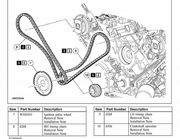
7 1. Position the crankshaft keyway at the 12 o'clock position. 2. Remove the bolts, the LH timing chain tensioner and tensioner arm. 7/22

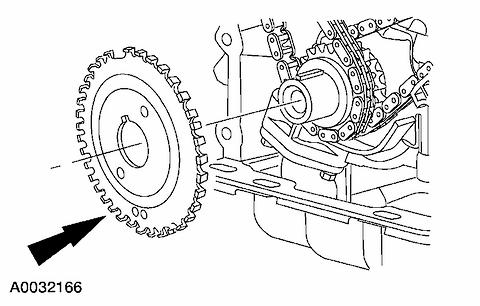
8 3. Remove the bolts, the RH timing chain tensioner and tensioner arm. 4. Remove the ignition pulse wheel from the crankshaft. 8/22

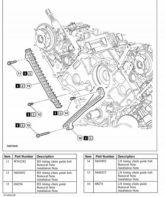
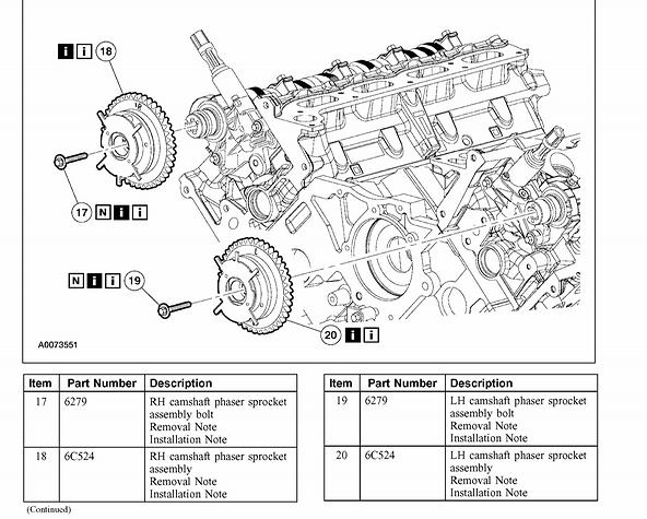
9 5. Remove the RH and LH timing chains and the crankshaft sprocket. - Remove the RH timing chain from the camshaft sprocket. - Remove the RH timing chain from the crankshaft sprocket. - Remove the LH timing chain from the camshaft sprocket. - Remove the LH timing chain and crankshaft sprocket. 6. Remove both timing chain guides. - Remove the bolts. - Remove both timing chain guides. Items 17-20: LH and RH Camshaft Phaser Sprocket Assembly and Bolt Removal Note 1. CAUTION: Only use hand tools to remove the camshaft phaser sprocket assembly or damage may occur to the camshaft or camshaft phaser unit. 9/22

10 CAUTION: Damage to the camshaft phaser sprocket assembly will occur if mishandled or used as a lifting or leveraging device. Using the special tool, remove the bolt and the RH camshaft phaser sprocket assembly. - Discard the bolt and washer. 2. CAUTION: Only use hand tools to remove the camshaft phaser sprocket assembly or damage may occur to the camshaft or camshaft phaser unit. CAUTION: Damage to the camshaft phaser sprocket assembly will occur if mishandled or used as a lifting or leveraging device. Using the special tool, remove the bolt and the LH camshaft phaser sprocket assembly. 10/22
11 - Discard the bolt and washer. 3. Inspect the front of the camshaft phaser and sprocket for missing or damaged roll pins. - If the roll pins are missing or damaged, a new camshaft phaser and sprocket must be installed. 4. Inspect the rear of the camshaft phaser and sprocket for a deformed or damaged location pin. - If the location pin is deformed or damaged a new camshaft phaser and sprocket must be installed. 11/22
12 5. Visually inspect the camshaft phaser and sprocket for squareness (A). If the trigger wheel or spring is deformed or damaged (B), install a new camshaft phaser and sprocket. Items 21-26: Variable Camshaft Timing (VCT) Housing and Bolts Removal Note 12/22
 Housing and Bolts Installation Note 1.")

13 1. Remove the bolts and the variable camshaft timing housing. - Discard the gasket. Items 21-26: Variable Camshaft Timing (VCT) Housing and Bolts Installation Note 1. Install a new gasket, the variable camshaft timing housing and the bolts. Items 17-20: RH and LH Camshaft Phaser Sprocket Assembly and Bolt Installation Note 13/22

14 1. Install the camshaft variable timing sprocket assembly and loosely install a new bolt and washer. 2. CAUTION: Only use hand tools to install the camshaft phaser sprocket assembly or damage may occur to the camshaft or camshaft phaser unit. CAUTION: Damage to the camshaft phaser sprocket assembly will occur if mishandled or used as a lifting or leveraging device. Using the special tool, tighten the bolt in two stages: - Stage 1: Tighten to 40 Nm (30 ft. lbs.). - Stage 2: Tighten an additional 90 degrees. 3. Repeat the previous steps for the LH camshaft phaser sprocket. Items 1-16: Timing Drive Components Installation Note 14/22
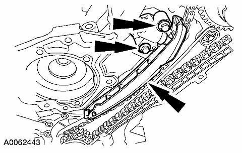
15 1. CAUTION: Timing chain procedures must be followed exactly or damage to valves and pistons will result. Compress the tensioner plunger, using a vice. 2. Install a retaining clip on the tensioner to hold the plunger in during installation. 3. Remove the tensioner from the vise. 15/22

16 4. If the copper links are not visible, mark two links on one end and one link on the other end, and use as timing marks. 5. NOTE: Crankshaft keyway must be positioned at the 12 o'clock position. Install the timing chain guides. 16/22
 timing chain on the crankshaft sprocket, aligning the timing mark on the outer flange of the crankshaft sprocket with the single copper (marked) link on the")
17 6. Install the crankshaft sprocket, making sure the flange faces forward. 7. Position the lower end of the LH (inner) timing chain on the crankshaft sprocket, aligning the timing mark on the outer flange of the crankshaft sprocket with the single copper (marked) link on the chain. 8. NOTE: Make sure the upper half of the timing chain is below the tensioner arm dowel. 17/22
 chain links. 9.")

18 Position the timing chain on the camshaft sprocket with the camshaft sprocket timing mark positioned between the two copper (marked) chain links. 9. NOTE: The LH timing chain tensioner arm has a bump near the dowel hole for identification. Position the LH timing chain tensioner arm on the dowel pin and install the LH timing chain tensioner. 18/22
 timing chain on the crankshaft sprocket, aligning the timing mark on the sprocket with the single copper (marked) chain link. 12.")
19 10. Remove the retaining clip from the LH timing chain tensioner. 11. Position the lower end of the RH (outer) timing chain on the crankshaft sprocket, aligning the timing mark on the sprocket with the single copper (marked) chain link. 12. NOTE: The lower half of the timing chain must be positioned above the tensioner arm dowel. 19/22
20 Position the RH timing chain on the camshaft sprocket. Make sure the camshaft sprocket timing mark is positioned between the two copper (marked) chain links. 20/22

21 13. Note: The camshaft phaser and sprocket will be stamped with one of the illustrated timing marks for the RH camshaft. Position the RH timing chain tensioner arm on the dowel pin and install the RH timing chain tensioner. 14. Remove the retaining clip from the RH timing chain tensioner. 15. NOTE: Both camshaft phaser sprockets are identical, refer to the R timing mark to identify the RH camshaft phaser sprocket and the L timing mark to identify the LH camshaft phaser sprocket. 21/22
22 As a post-check, verify correct alignment of all timing marks. Make sure the R and L timing marks on the sprockets correspond with the above note. 16. Install the crankshaft sensor ring on the crankshaft. 22/22
Timing Drive Components
 IN VEHICLE REPAIR: TIMING DRI... IN VEHICLE REPAIR: TIMING DRIVE COMPONENTS (ENGINE 5.4L (3V)) 303 01B Engine 5.4L (3V) 2004 F 150 IN VEHICLE REPAIR Procedure revision date: 03/14/2006 Timing Drive Components
Timing Drive Components
 1 of 27 3/9/2012 8:26 AM Timing Drive Components Special Tool(s) Material LLDATA Online - 2006 Ford Truck Expedition 4WD V8-5.4L VIN 5 -... 2 of 27 3/9/2012 8:26 AM Material Removal 1. Remove the engine
CAUTION: Do not compress the ratchet assembly. This will damage the ratchet assembly.
 Installation Engines with ratcheting timing chain tensioners 1. CAUTION: Timing chain procedure must be followed exactly or damage to valves and pistons will result. CAUTION: Do not compress the ratchet
IN-VEHICLE REPAIR. Timing Drive Components. Removal. 3. Position the crankshaft keyway at the 12 o clock position.
 303-01C-1 IN-VEHICLE REPAIR Timing Drive Components 303-01C-1 Special Tool(s) Compressor, Valve Spring 303-1039 Locking Tool, Camshaft Phaser Sprocket 303-1046 3. Position the crankshaft keyway at the
SECTION C Engine 5.4L (3V)
") 303-01C-i Engine 5.4L (3V) 303-01C-i SECTION 303-01C Engine 5.4L (3V) CONTENTS PAGE IN-VEHICLE REPAIR Timing Drive Components... 303-01C-2 303-01C-2 Engine 5.4L (3V) 303-01C-2 IN-VEHICLE REPAIR Timing
303-01C-i Engine 5.4L (3V) 303-01C-i SECTION 303-01C Engine 5.4L (3V) CONTENTS PAGE IN-VEHICLE REPAIR Timing Drive Components... 303-01C-2 303-01C-2 Engine 5.4L (3V) 303-01C-2 IN-VEHICLE REPAIR Timing
 Page 1 of 18 303-01C Engine 5.4L (3V) 2010 F-150 IN-VEHICLE REPAIR Procedure revision date: 07/01/2009 Timing Drive Components Special Tool(s) Compressor, Valve Spring 303-1039 Holding Tool, Crankshaft
IN-VEHICLE REPAIR. Timing Drive Components. Removal. 3. Position the crankshaft keyway at the 12 o clock position.
 303-01B-1 IN-VEHICLE REPAIR Timing Drive Components 303-01B-1 Special Tool(s) Compressor, Valve Spring 303-1039 Locking Tool, Camshaft Phaser Sprocket 303-1046 3. Position the crankshaft keyway at the
Timing Drive Components
 2006 Ford F 150 : Engine Mechanical > Engine, 5.4L (3V) > IN VEHICLE REPAIR > Timing Drive Components Timing Drive Components Listen SECTION 303 01C: Engine 5.4L (3V) 2006 F 150/Mark LT Workshop Manual
IN-VEHICLE REPAIR. Timing Drive Components. Removal. 3. Disconnect the eight ignition coil electrical connectors.
 303-01A-1 IN-VEHICLE REPAIR Timing Drive Components 303-01A-1 Special Tool(s) Compressor, Valve Spring 303-581 (T97T-6565-A) Holding Tool, Crankshaft 303-448 (T93P-6303-A) 3. Disconnect the eight ignition
SECTION C Engine 5.4L (4V)
") 303-01C-i Engine 5.4L (4V) 303-01C-i SECTION 303-01C Engine 5.4L (4V) CONTENTS PAGE IN-VEHICLE REPAIR Timing Drive Components... 303-01C-2 303-01C-2 Engine 5.4L (4V) 303-01C-2 IN-VEHICLE REPAIR Timing
303-01C-i Engine 5.4L (4V) 303-01C-i SECTION 303-01C Engine 5.4L (4V) CONTENTS PAGE IN-VEHICLE REPAIR Timing Drive Components... 303-01C-2 303-01C-2 Engine 5.4L (4V) 303-01C-2 IN-VEHICLE REPAIR Timing
2002 Escape Workshop Manual
 SECTION 303-01B: Engine 3.0L (4V) IN-VEHICLE REPAIR Procedure revision date: 10/09/2003 Timing Drive Components Removal CAUTION: Failure to verify correct timing drive component alignment will result in
2000 Lincoln LS Workshop Manual
 Page 1 of 10 SECTION 303-01B: Engine 3.9L 2000 Lincoln LS Workshop Manual IN-VEHICLE REPAIR Procedure revision date: 03/17/1999 Timing Drive Components Primary Special Tool(s) Camshaft Setting/Locking
Intake Components 1117
 Item Part Number Description 1 W705654 Bolt 2 N807309 Bolt (2 req'd) 3 9F460 Bracket 4 N807071 Bolt (5 req'd) 5 9A448 Intake manifold (upper) 6 9E498 Vacuum harness 7 9F792 Fuel injection supply manifold
Service and Repair. Material. Timing chain
 ALLDATA Online - 1999 Mercury Cougar V6-153 2.5L DOHC VIN L SFI - Service and... Page 1 of 16 Service and Repair Notes Material Timing chain 1. Remove and discard the camshaft seal. 2. Remove the engine
Zoom and Print Options
 Vehicle» Engine, Cooling and Exhaust» Engine» Cylinder Head Assembly» Rocker Arm Assembly» Service and Repair» Procedures» Cam, Valve Springs & Seals, Cam Roller Follower and Lifter Camshaft, Valve Springs,
Timing Drive Components ( )
") Page 1 of 14 (12.65.13) Removal 1. Remove the engine front cover. For additional information, refer to For additional information, refer to. 2. Remove the spark plugs. 3. Remove the crankshaft position
Page 1 of 14 (12.65.13) Removal 1. Remove the engine front cover. For additional information, refer to For additional information, refer to. 2. Remove the spark plugs. 3. Remove the crankshaft position
Zoom and Print Options
 Vehicle» Engine, Cooling and Exhaust» Engine» Cylinder Head Assembly» Service and Repair» Procedures» Removal Cylinder Heads http://repair.alldata.com/alldata/article/display.action?componentid=65&itypeid=376&nonstandardid=682956&vehicleid=45317&windowname=maina
CAMSHAFT TIMING CHAIN, SPROCKET, AND TENSIONER REPLACEMENT
 Page 1 of 45 CAMSHAFT TIMING CHAIN, SPROCKET, AND TENSIONER REPLACEMENT Special Tools J 45027 Tensioner Tool J 45059 Angle Meter Page 2 of 45 Removal Procedure Page 3 of 45 Page 4 of 45 Page 5 of 45 Fig.
Engine. Special Tool(s) Compressor, Valve Spring (T97P-6565-AH) Compressor Spacer, Valve Spring (T91P-6565-AH)
 Compressor, Valve Spring (T97P-6565-AH) Compressor Spacer, Valve Spring (T91P-6565-AH)") Page 1 of 41 SECTION 303-01A: Engine 5.4L (2V) 2000 F-Super Duty 250-550/Excursion/F-53 Motorhome Chassis Workshop Manual ASSEMBLY Procedure revision date: 04/04/2003 Engine Special Tool(s) Compressor,
Page 1 of 41 SECTION 303-01A: Engine 5.4L (2V) 2000 F-Super Duty 250-550/Excursion/F-53 Motorhome Chassis Workshop Manual ASSEMBLY Procedure revision date: 04/04/2003 Engine Special Tool(s) Compressor,
2002 Crown Victoria/Grand Marquis Workshop Manual
 Page 1 of 24 SECTION 303-01: Engine 2002 Crown Victoria/Grand Marquis Workshop Manual INSTALLATION Procedure revision date: 01/02/2003 Cylinder Heads Special Tool(s) Installer, Crankshaft Vibration Damper
file://c:\program Files\tsocache\OFFICE_5416\SY1~us~en~file=SY131B46.htm~gen~ref...
 Page 1 of 41 SECTION 303-01B: Engine 4.6L and 5.4L 2000 F-150 Workshop Manual ASSEMBLY Procedure revision date: 01/27/2004 Engine 4.6L Special Tool(s) Compressor, Valve Spring 303-567 (T97P-6565-AH) Compressor
2007 Ford Freestyle SEL
 Fig. 279: Exploded View Of Engine Heads, Intake & Exhaust Components Item Part Number Description 1 9D475 Exhaust gas recirculation (EGR) system module 2 9D477 EGR module tube 3 9F485 RH exhaust manifold
 Page 1 of 21 303-01C Engine 5.4L (3V) 2009 F-150 REMOVAL Procedure revision date: 03/26/2009 Cylinder Head Special Tool(s) 3 Jaw Puller 303-D121 or equivalent Compressor, Valve Spring 303-1039 Holding
11/29/2017 Engine Cooling - Coolant Pump - Removal and Installation 2010 Ford Edge MotoLogic Engine Cooling 2010 Edge, MKX
 2010 Edge Report a problem with this article 303-03 Engine Cooling 2010 Edge, MKX REMOVAL AND INSTALLATION Procedure revision date: 10/04/2010 Coolant Pump Special Tool(s) Camshaft Holding Tool 303-1248
Cylinder Head. Special Tool(s) 3-Jaw Puller 303-D121 or equivalent. Compressor, Valve Spring
 3-Jaw Puller 303-D121 or equivalent. Compressor, Valve Spring") SECTION 303-01B: Engine 4.6L (3V) 2009 Mustang Workshop Manual REMOVAL Procedure revision date: 03/15/2009 Cylinder Head Special Tool(s) 3-Jaw Puller 303-D121 or equivalent Compressor, Valve Spring 303-1039
SECTION 303-01B: Engine 4.6L (3V) 2009 Mustang Workshop Manual REMOVAL Procedure revision date: 03/15/2009 Cylinder Head Special Tool(s) 3-Jaw Puller 303-D121 or equivalent Compressor, Valve Spring 303-1039
Camshaft Timing Chain, Sprocket, And Tensioner Replacement
 2007 Pontiac Solstice - Engine Mechanical > Engine Mechanical - 2.0L > Repair Instructi... Page 1 of 29 2007 Pontiac Solstice : Engine Mechanical > Engine Mechanical - 2.0L > Repair Instructions - On Vehicle
2/22/2018 Camshaft Timing Drive Components Cleaning and Inspection 2007 Saturn Aura MotoLogic
 2007 Aura Applies to: 3.6L Report a problem with this article Cleaning Procedure Important: Some models use a second design inverted tooth timing drive system on the secondary drive components. Refer to
IN-VEHICLE REPAIR. Camshaft RH. Removal. 2. Remove the RH valve cover. For additional information, refer to Valve Cover RH in this section.
 303-01C-1 IN-VEHICLE REPAIR Camshaft RH Special Tool(s) 303-01C-1 2. Remove the RH valve cover. For additional information, refer to Valve Cover RH in this section. Compressor, Valve Spring 3. NOTICE:
REMOVAL. Cylinder Head. All cylinder heads. 1. Remove the engine. For additional information, refer to Engine in this section.
 303-01B-1 303-01B-1 REMOVAL Cylinder Head Material Item Specification Special Tool(s) Motorcraft Metal Surface Prep Modular Engine Lift Bracket ZC-31 303-F047 (014-00073) or equivalent Silicone Gasket
DISASSEMBLY. Engine. Special Tool(s) Locking Tool, Camshaft Phaser Sprocket Special Tool(s)
 Locking Tool, Camshaft Phaser Sprocket Special Tool(s)") 303-01B-1 DISASSEMBLY Engine Special Tool(s) Remover, Crankshaft Rear Slinger 303-514 (T95P-6701-AH) Special Tool(s) 303-01B-1 Locking Tool, Camshaft Phaser Sprocket 303-1046 Remover, Crankshaft Rear Seal
303-01B-1 DISASSEMBLY Engine Special Tool(s) Remover, Crankshaft Rear Slinger 303-514 (T95P-6701-AH) Special Tool(s) 303-01B-1 Locking Tool, Camshaft Phaser Sprocket 303-1046 Remover, Crankshaft Rear Seal
6.0 Liter Timing Chain, Crankshaft Sprocket, Camshaft Position Actuator, and Solenoid Valve Replacement
 Special Tools EN 46330 Timing Belt Tensioner Retaining Pin J 8433 Two Jaw Puller J 41478 Crankshaft Front Oil Seal Installer J 41558 Crankshaft Sprocket Remover J 41665 Crankshaft Balancer and Sprocket
IN-VEHICLE REPAIR. Timing Drive Components Camshaft Drive Cassette, LH. Special Tool(s) Holding Tool, Camshaft Sprocket (T97T-6256)
 Holding Tool, Camshaft Sprocket (T97T-6256)") 303-01A-1 IN-VEHICLE REPAIR Timing Drive Components Camshaft Drive Cassette, LH 303-01A-1 Special Tool(s) Holding Tool, Camshaft Sprocket 303-564 (T97T-6256) Adapter for 303-564 303-578 (T97T-6256-A) Holding
303-01A-1 IN-VEHICLE REPAIR Timing Drive Components Camshaft Drive Cassette, LH 303-01A-1 Special Tool(s) Holding Tool, Camshaft Sprocket 303-564 (T97T-6256) Adapter for 303-564 303-578 (T97T-6256-A) Holding
Removal Procedure. Remove the timing chain tensioner. 1 of 32 12/17/ :42 AM
 1 of 32 12/17/2011 11:42 AM Removal Procedure 1. 2. 3. 4. 5. 6. Remove the camshaft cover. Raise and support the vehicle. Remove the No. 1 cylinder spark plug. Rotate the crankshaft in the engine rotational
IN-VEHICLE REPAIR. Camshaft RH. Removal. 2. Remove the RH valve cover. For additional information, refer to Valve Cover RH in this section.
 303-01B-1 IN-VEHICLE REPAIR Camshaft RH Special Tool(s) Compressor, Valve Spring 303-1039 Wedge, Timing Chain 303-1175 303-01B-1 2. Remove the RH valve cover. For additional information, refer to Valve
CAUTION: When aligning timing marks, always rotate engine by turning the crankshaft. Failure to do so will result in valve and/or piston damage.
 REMOVAL Timing Chain 1. Disconnect negative battery cable. 2. Drain cooling system. 3. Remove upper intake manifold. 4. Remove cylinder head covers, crankshaft vibration damper, and timing chain cover.
2003 Hyundai Sonata LX
 TIMING & COUNTERBALANCE SHAFT BELTS Removal CAUTION: DO NOT rotate engine counterclockwise (as viewed from timing belt end of engine). If reusing timing belt, place reference mark on timing belt to indicate
Timing Drive Components Camshaft Timing
 SECTION 303-01B: Engine 4.0L SOHC 1998 Explorer/Mountaineer Workshop Manual IN-VEHICLE REPAIR Procedure revision date: 10/17/2002 Timing Drive Components Camshaft Timing Special Tool(s) Timing Chain Tensioner
Cylinder Head. Special Tool(s) Compressor, Valve Spring (T93P-6565-AR) Heavy Duty Floor Crane or equivalent
 Compressor, Valve Spring (T93P-6565-AR) Heavy Duty Floor Crane or equivalent") SECTION 303-01C: Engine 5.4L (4V) 2009 Mustang Workshop Manual INSTALLATION Procedure revision date: 04/03/2009 Cylinder Head Special Tool(s) Compressor, Valve Spring 303-452 (T93P-6565-AR) Heavy Duty
SECTION 303-01C: Engine 5.4L (4V) 2009 Mustang Workshop Manual INSTALLATION Procedure revision date: 04/03/2009 Cylinder Head Special Tool(s) Compressor, Valve Spring 303-452 (T93P-6565-AR) Heavy Duty
2002 Explorer Sport/Sport Trac Workshop Manual
 Page 1 of 17 SECTION 303-01: Engine 4.0L Single Overhead Camshaft (SOHC) IN-VEHICLE REPAIR Procedure revision date: 07/13/2005 Cylinder Head Special Tool(s) Spark Plug Wire Remover 303-106 (T74P-6666-A)
CAMSHAFT TIMING CHAIN, SPROCK... CAMSHAFT TIMING CHAIN, SPROCKET, AND TENSIONER REPLACEMENT (LE5 OR LE9) (ENGINE MECHANICAL - 2.2L OR 2.
 (ENGINE MECHANICAL - 2.2L OR 2.") CAMSHAFT TIMING CHAIN, SPROCK... CAMSHAFT TIMING CHAIN, SPROCKET, AND TENSIONER REPLACEMENT (LE5 OR LE9) (ENGINE MECHANICAL - 2.2L OR 2.4L) Document ID# 2133175 Camshaft Timing Chain, Sprocket, and Tensioner
CAMSHAFT TIMING CHAIN, SPROCK... CAMSHAFT TIMING CHAIN, SPROCKET, AND TENSIONER REPLACEMENT (LE5 OR LE9) (ENGINE MECHANICAL - 2.2L OR 2.4L) Document ID# 2133175 Camshaft Timing Chain, Sprocket, and Tensioner
TIMING CHAIN. TIMING CHAIN Removal and Installation EM-35 PFP:13028 EBS00I2X KBIA2511E
 TIMING CHAIN Removal and Installation PFP:13028 EBS00I2X A EM C D E F G H I J K L M KBIA2511E EM-35 1. Camshaft sprocket (left bank EXH) 2. Camshaft sprocket (left bank INT) 3. Camshaft sprocket (right
 Page 1 of 75 303-01D Engine - 5.2L 32V Ti-VCT 2016 Mustang Assembly Procedure revision date: 12/15/2016 Special Tool(s) / General Equipment Engine Base Part Number: 6L084 205-142 (T80T-4000-J) Installer,
Crankshaft, Remove and Install (Engine Removed) (Z 22 SE)
 (Z 22 SE)") Page 1 of 36 Crankshaft, Remove and Install (Engine Removed) (Z 22 SE) Remove 1. Remove the engine Note: See operation "Engine, Remove and Install". 2. Separate the manual transmission from the engine.
Page 1 of 36 Crankshaft, Remove and Install (Engine Removed) (Z 22 SE) Remove 1. Remove the engine Note: See operation "Engine, Remove and Install". 2. Separate the manual transmission from the engine.
Classification: Reference: Date: VE30DE CAM TIMING
 Classification: Reference: Date: EM93-002 NTB93-126 September 2, 1993 VE30DE CAM TIMING APPLIED VEHICLE(S): All equipped with VE30DE Engine SERVICE INFORMATION When servicing VE30DE engine cylinder heads,
Engine. Special Tool(s) Compressor, Piston Ring 303-D032 (D81L-6002-C) or equivalent. Compressor, Valve Spring (T93P-6565-AR)
 Compressor, Piston Ring 303-D032 (D81L-6002-C) or equivalent. Compressor, Valve Spring (T93P-6565-AR)") SECTION 303-01C: Engine 5.4L (4V) 2009 Mustang Workshop Manual ASSEMBLY Procedure revision date: 12/12/2008 Engine Special Tool(s) Compressor, Piston Ring 303-D032 (D81L-6002-C) or equivalent Compressor,
SECTION 303-01C: Engine 5.4L (4V) 2009 Mustang Workshop Manual ASSEMBLY Procedure revision date: 12/12/2008 Engine Special Tool(s) Compressor, Piston Ring 303-D032 (D81L-6002-C) or equivalent Compressor,
REMOVAL & INSTALLATION
 REMOVAL & INSTALLATION CAUTION: This application is an interference engine. Do not rotate camshaft or crankshaft when timing belt is removed, or engine damage may occur. TIMING & COUNTERBALANCE SHAFT BELTS
3/6/2017 Timing Chain Service and Repair, Removal and Replacement: Valve Timing, Installing and Adjusting
 Valve timing, adjusting Special tools and equipment - T10068 Camshaft bar - T10069 Counter support - VAG 1331 Torque wrench (5-50 Nm) - VAG 1332 Torque wrench (40-200 Nm) - AMV 174 004 01 Sealing compound
9/24/2017 Camshaft Timing Chain Removal and Installation Engine Mechanical 2002 Audi A6/S6/Quattro/Allroad MotoLogic
 2002 A6/S6/Quattro/Allroad The information in this article comes from a service manual containing information that applies to the following engine code: BAS. Section Info: Report a problem with this article
3/15/2015 1:10 PM TIMING CHAIN REMOVAL/INSTALLATION [L3 WITH TC]
![3/15/2015 1:10 PM TIMING CHAIN REMOVAL/INSTALLATION [L3 WITH TC]](/thumbs/93/113245190.jpg "3/15/2015 1:10 PM TIMING CHAIN REMOVAL/INSTALLATION [L3 WITH TC]") 1 of 17 TIMING CHAIN REMOVAL/INSTALLATION [L3 WITH TC] 1. Disconnect the negative battery cable. 2. Remove the under cover. 3. Remove the front wheels and tires (RH). 4. Remove the splash shield. 5. Remove
1 of 17 TIMING CHAIN REMOVAL/INSTALLATION [L3 WITH TC] 1. Disconnect the negative battery cable. 2. Remove the under cover. 3. Remove the front wheels and tires (RH). 4. Remove the splash shield. 5. Remove
1 of 10 2/10/2017 5:20 PM
 1 of 10 2/10/2017 5:20 PM Crankshaft Pulley Removal NOTICE: Do not loosen or remove the crankshaft pulley bolt without first installing the special tools as instructed in this procedure. The crankshaft
2010 Transit Connect Workshop Manual. 31. Remove the 3 bolts, thermostat housing and thermostat.
 31. Remove the 3 bolts, thermostat housing and thermostat. 32. Remove the 2 bolts, stud bolt and the A/C compressor. 33. Remove the bolt and the KS. 34. Remove the 8 bolts and the crankcase vent oil separator.
MECHANICAL(H4DOTC DIESEL) > Cylinder Block INSTALLATION 1. After setting the cylinder block to ST, install the crankshaft bearing.
 > Cylinder Block INSTALLATION 1. After setting the cylinder block to ST, install the crankshaft bearing.") MECHANICAL(H4DOTC DIESEL) > Cylinder Block INSTALLATION 1. After setting the cylinder block to ST, install the crankshaft bearing. ST 499817100 ENGINE STAND Apply a coat of engine oil to the bearing and
MECHANICAL(H4DOTC DIESEL) > Cylinder Block INSTALLATION 1. After setting the cylinder block to ST, install the crankshaft bearing. ST 499817100 ENGINE STAND Apply a coat of engine oil to the bearing and
2005 Chrysler 300 C ENGINE Mechanical - 3.5L - Service Information & Magnum
 1. Install camshaft sprockets onto the camshafts. Install NEW sprocket attaching bolts into place. The 255 mm (10 in.) bolt is to be installed in the left camshaft and the 213 mm (8 3/8 in.) bolt is to
ASSEMBLY Procedure revision date: 11/22/2001
 Page 1 of 39 Evan Groenke From: Daniel Lelovic [dlelovic@rogers.com] Sent: May 8, 2005 12:08 PM To: 'Evan Groenke' Subject: 2.5L Engine Re-assembly SECTION 303-01B: Engine 2.5L 2000 Contour/Mystique Workshop
1 of 12 11/20/2016 9:32 PM
 1 of 12 11/20/2016 9:32 PM Caution: After removing timing chain, do not turn crankshaft and camshaft separately, or valves will strike piston heads. Apply new engine oil to the sliding surfaces when Installing
Testing and Inspection. Diagnostic Procedure Step 1-2
 1 of 4 5/22/2008 7:54 AM Home Account Contact ALLDATA Log Out Help Select Vehicle New TSBs Technician's Reference Component Search: METRO TOYOTA OK 2002 Nissan-Datsun Altima 2.5 S L4-2.5L (QR25DE) Vehicle
DESCRIPTION AND OPERATION
 303-01B-10 Engine 3.0L 303-01B-10 DESCRIPTION AND OPERATION Upper Engine Components G72932 en 303-01B-11 Engine 3.0L 303-01B-11 DESCRIPTION AND OPERATION (Continued) Item Part Number Description 1 9H589
1999 Nissan Altima GLE
 TIMING CHAIN CAUTION: If cylinder head is installed and timing chain is disconnected, DO NOT rotate camshaft or crankshaft; valves will contact pistons, resulting in bent valves. NOTE: Following procedure
1991 Nissan 240SX. 2.4L 4-CYL - VINS [F,M,S] 1991 ENGINES Nissan 2.4L 4-Cylinder
![1991 Nissan 240SX. 2.4L 4-CYL - VINS [F,M,S] 1991 ENGINES Nissan 2.4L 4-Cylinder](/thumbs/95/123571962.jpg "1991 Nissan 240SX. 2.4L 4-CYL - VINS [F,M,S] 1991 ENGINES Nissan 2.4L 4-Cylinder") NOTE: Use illustration for component reference. See Fig. 7. 1. Remove spark plug wires. Set No. 1 piston at TDC on its compression stroke. Remove vacuum hoses, electrical harnesses, connectors, and harness
NOTE: Use illustration for component reference. See Fig. 7. 1. Remove spark plug wires. Set No. 1 piston at TDC on its compression stroke. Remove vacuum hoses, electrical harnesses, connectors, and harness
E03 CYLINDER HEAD ASSY 1 BN0030 Dowel Pin 4
 E01 FAN COVER ASSY 1 BN0061-1 Clip 1 2 150ZT-E01.02 BN0064 Fan Cover 1 3 BN0061-2 Bracket 1 4 150ZT-E01.04 BN0064-4 Carburetor Cooling Duct 1 5 150ZT-E01.05 BN0064-3 Decorative Cover 1 6 150ZT-E01.06 BN0063-2
Zoom and Print Options
 Vehicle» Engine, Cooling and Exhaust» Engine» Timing Components» Timing Chain» Service and Repair» Procedures» Timing Chain and Sprockets Replacement Timing Chain and Sprockets Replacement Tools Required
Mazda3 - Workshop Manual - Engine
 Page 1 of 18 2005 - Mazda3 - Workshop Manual - Engine TIMING CHAIN REMOVAL/INSTALLATION WARNING: Fuel vapor is hazardous. It can very easily ignite, causing serious injury and damage. Always keep sparks
2001 Dodge Dakota ENGINES 4.7L V8
 FRONT COVER Removal & Installation 1. Disconnect negative battery cable. Remove drive belt. Remove A/C compressor mounting bolts, and position compressor aside. Drain cooling system. Remove radiator hoses.
Toyota Truck Pickup 2WD L4-2.4L SOHC (22R) 1987
 1987") Timing Chain: Service and Repair Toyota Truck Pickup 2WD L4-2.4L SOHC (22R) 1987 PREPARATION FOR REMOVAL OF TIMING CHAIN 1. REMOVE CYLINDER HEAD 2. REMOVE RADIATOR 3. REMOVE OIL PAN (a) Remove the engine
Timing Chain: Service and Repair Toyota Truck Pickup 2WD L4-2.4L SOHC (22R) 1987 PREPARATION FOR REMOVAL OF TIMING CHAIN 1. REMOVE CYLINDER HEAD 2. REMOVE RADIATOR 3. REMOVE OIL PAN (a) Remove the engine
E02 CYLINDER HEAD COVER ASSY
 TNG 150cc ZT E01 FAN COVER ASSY 1 BN0061-1 Clip 1 2 150ZT-E01.02 BN0064 Fan Cover 1 3 BN0061-2 Bracket 1 4 150ZT-E01.04 BN0064-4 Carburetor Cooling Duct 1 5 150ZT-E01.05 BN0064-3 Decorative Cover 1 6 150ZT-E01.06
2007 Explorer/Mountaineer/Explorer Sport Trac Workshop Manual SECTION A: Engine 4.0L SOHC. IN-VEHICLE REPAIR Procedure revision date: 04/20/2006
 SECTION 303-01A: Engine 4.0L SOHC 2007 Explorer/Mountaineer/Explorer Sport Trac Workshop Manual IN-VEHICLE REPAIR Procedure revision date: 04/20/2006 Camshaft Drive Cassette LH Printable View (577 KB)
DISASSEMBLY. Engine. CAUTION: Remove the cylinder heads before removing the crankshaft. Failure to do so can result in engine damage.
 303-01A-1 DISASSEMBLY Engine Special Tool(s) Remover, Crankshaft Vibration Damper 303-101 (T74P-3616-A) Special Tool(s) Crankshaft Socket 303-674 303-01A-1 Remover, Crankshaft Vibration Damper 303-773
IN-VEHICLE REPAIR. Engine Front Cover
 303-01B-1 IN-VEHICLE REPAIR Engine Front Cover Material Item Specification 303-01B-1 Special Tool(s) Motorcraft SAE 5W-20 WSS-M2C930-A Premium Synthetic Blend 3-Jaw Puller Motor Oil 303-D121 XO-5W20-QSP
Tech Talk. Timing Belt 6VD1/6VE1
 Holden DOHC V6 Frontera 6VD1 3.2L 1999 2004 Jackaroo 6VE1 3.5L 1998 2004 Rodeo TF 6VD1 3.2L 1998 2003 Rodeo RA 6VE1 3.5L 2003 2005 Important: Read through all the instructions before proceeding with the
DISASSEMBLY Procedure revision date: 11/22/2001
 Page 1 of 31 Evan Groenke From: Daniel Lelovic [dlelovic@rogers.com] Sent: May 8, 2005 12:06 PM To: 'Evan Groenke' Subject: 2.5 L Engine Disassembly SECTION 303-01B: Engine 2.5L 2000 Contour/Mystique Workshop
15.Timing Chain Assembly
 15. A: REMOVAL 1. TIMING CHAIN RH When replacing a single part, perform the work with the engine assembly installed to body. 1) Remove the chain cover. 2) Using
TIMING BELT REMOVAL - TIMING BELT
 2004 Chrysler Concorde V6-3.5L VIN M Vehicle > Engine, Cooling and Exhaust > Engine > Timing Components > Timing Belt > Service and Repair > Procedures TIMING BELT REMOVAL - TIMING BELT CAUTION: The following
4. Remove the charge air cooler. (See INTAKE AIR SYSTEM REMOVAL/INSTALLATION [L3 WITH TC].)
![4. Remove the charge air cooler. (See INTAKE AIR SYSTEM REMOVAL/INSTALLATION [L3 WITH TC].)](/thumbs/96/128786582.jpg "4. Remove the charge air cooler. (See INTAKE AIR SYSTEM REMOVAL/INSTALLATION [L3 WITH TC].)") TIMING CHAIN REMOVAL/INSTALLA... < Previous Next > 2007 Mazda3 Engine TIMING CHAIN REMOVAL/INSTALLATION [L3 WITH TC] 1. Remove the battery cover. 2. Disconnect the negative battery cable. 3. Remove the
TIMING CHAIN REMOVAL/INSTALLA... < Previous Next > 2007 Mazda3 Engine TIMING CHAIN REMOVAL/INSTALLATION [L3 WITH TC] 1. Remove the battery cover. 2. Disconnect the negative battery cable. 3. Remove the
TECHNICAL SERVICE BULLETIN
 TECHNICAL SERVICE BULLETIN SUBJECT: NO.: 09-15-93 Camshaft Timing Belt Replacement/Adjustment GROUP: Engine Service Procedure DATE: Sep.17, 1993 This Bulletin Is Supplied As Technical Information Only
Valve Timing, Adjust (Z 22 SE)
") Page 1 of 15 Valve Timing, Adjust (Z 22 SE) Remove 1. Open the bonnet. 2. Disconnect the battery. 3. Open the engine cover (1). 4. Detach the engine cover. 6 bolts (2) and (3) 5. Release the fuel pressure.
Page 1 of 15 Valve Timing, Adjust (Z 22 SE) Remove 1. Open the bonnet. 2. Disconnect the battery. 3. Open the engine cover (1). 4. Detach the engine cover. 6 bolts (2) and (3) 5. Release the fuel pressure.
2003 Nissan-Datsun Truck Frontier 4WD V6-3.3L (VG33E)
") 1 of 15 8/7/2016 2:34 PM 2003 Nissan-Datsun Truck Frontier 4WD V6-3.3L (VG33E) Vehicle» Engine, Cooling and Exhaust» Engine» Cylinder Head Assembly» Service and Repair» Removal and Installation 2 of 15
1 of 15 8/7/2016 2:34 PM 2003 Nissan-Datsun Truck Frontier 4WD V6-3.3L (VG33E) Vehicle» Engine, Cooling and Exhaust» Engine» Cylinder Head Assembly» Service and Repair» Removal and Installation 2 of 15
Timing Chain: Service and Repair With 2 Piece Tensioner (TSB A) Precaution. Removal This article has been updated with bulletin No A.
 Precaution. Removal This article has been updated with bulletin No A.") 1997 Chevrolet Cavalier L4-144 2.4L DOHC VIN T SFI Page 1 Timing Chain: Service and Repair With 2 Piece Tensioner (TSB 67-61-22A) Precaution Bulletin No.: 67-61-22A Date: July, 1998 TIMING CHAIN TENSIONER
1997 Chevrolet Cavalier L4-144 2.4L DOHC VIN T SFI Page 1 Timing Chain: Service and Repair With 2 Piece Tensioner (TSB 67-61-22A) Precaution Bulletin No.: 67-61-22A Date: July, 1998 TIMING CHAIN TENSIONER
SECTION C Engine 6.0L Diesel
 303-01C-i Engine 6.0L Diesel 303-01C-i SECTION 303-01C Engine 6.0L Diesel CONTENTS PAGE IN-VEHICLE REPAIR Cylinder Head RH... 303-01C-2 303-01C-2 Engine 6.0L Diesel 303-01C-2 IN-VEHICLE REPAIR Cylinder
LIFAN 125cc K-START ENGINE CATALOGUE
 REF # PART # LIFAN 125cc K-START ENGINE CATALOGUE DESCRI PTI ON 1.Cylinder Head Cover qty per bike 1 12311/1P50FMG Cover, cylinder head 1 2 12240/1P50FMG Cover comp., cylinder head, RH 1 3 12242/1P50FMG-3
Chrysler 2.0L DOHC timing belt procedure REMOVAL
 Chrysler 2.0L DOHC timing belt procedure REMOVAL CAUTION: Camshaft or crankshaft should not be rotated after timing belt is removed. Damage to valve components may occur. Always align timing marks before
3. Using the ST, align the Top mark on crank sprocket to nine o clock position as shown in the figure
 2008 Tribeca (3.6L) MECHANICAL(H6DO) > Timing Chain Assembly Report a problem with this article INSTALLATION Be careful that the foreign matter is not into or onto assembled component during installation.
1. Disconnect negative battery cable. 2. Remove upper and lower front timing belt covers..
 BELT AND SPROCKETS-TIMING REMOVAL TIMING BELT Zoom 1. Disconnect negative battery cable. 2. Remove upper and lower front timing belt covers.. CAUTION: When aligning crankshaft and camshaft timing marks
2000 Nissan Altima SE
 Removal 1. Release fuel pressure. See FUEL PRESSURE RELEASE. Drain coolant from radiator and cylinder block. Drain engine oil. Disconnect all necessary coolant hoses, electrical connectors, vacuum hoses,
8/28/2018 Engine 6.0L Diesel - Cylinder Head RH - in Vehicle Repair 2006 Ford F-550 MotoLogic. Specification
 2006 F-550 Applies to: 6.0L Diesel Report a problem with this article SECTION 303-01C: Engine 6.0L Diesel 2006 F-Super Duty 250-550 Workshop Manual IN-VEHICLE REPAIR Procedure revision date: 05/03/2006
TIMING CHAIN COMPONENTS
 Page 1 of 30 TIMING CHAIN COMPONENTS Fig. 46: Identifying Camshaft Timing Oil Control Valve Assembly Components With Torque Page 2 of 30 Specifications (1 Of 3) Fig. 47: Identifying Camshaft Timing Oil
GM 6-Cylinder Cam Tool Set 3.0L and 3.2L Operating Instructions
 GM 6-Cylinder Cam Tool Set 3.0L and 3.2L Operating Instructions Set Includes: Locking Tool... 536594 Locking Tool... 536595 Crankshaft Holding Tool... 536596 Alignment Gauge... 536608 Belt Installation
Mazda North American Operations Irvine, CA
 Service Bulletin Mazda North American Operations Irvine, CA 92618-2922 Subject: VARIABLE VALVE TIMING (VVT) NOISE AND/OR TIMING CHAIN NOISE Bulletin No: 01-012/12 MULTI-MODEL (L3 TURBO) - VARIABLE VALVE
PEUGEOT / 206 CC 1.6i 16V / 09/ /2007 / Cabriolet Country of manufacture EU Cubic capacity/power 1.6 / 80 kw Motor tag RB key PEU 814
 1 Vehicle PEUGEOT / 206 CC 1.6i 16V / 09/2000-03/2007 / Cabriolet Country of manufacture EU Cubic capacity/power 1.6 / 80 kw Motor tag NFU RB key PEU 814 Replacement Interval Guide Peugeot recommend: 206:
3/13/ :32 AM. NOTICE: Do not disconnect the hose.
 1 of 25 REPLACEMENT 1. REMOVE HOOD SUB-ASSEMBLY 2. REMOVE FRONT WHEEL RH 3. REMOVE ENGINE UNDER COVER LH 4. REMOVE ENGINE UNDER COVER RH 5. REMOVE FRONT FENDER APRON SEAL RH 6. DRAIN ENGINE OIL a. Install
2/18/2017 Cylinder Head Assembly Service and Repair, Removal and Replacement: Cylinder Head
 Cylinder Head http://repair.alldata.com/alldata/article/display.action?componentid=65&itypeid=401&nonstandardid=2762152&vehicleid=47645&miles=&printfriendl 1/17 RH Splash Shield Accessory Drive Belt, Thermostat
Replacement Parts & Accessories Price List
 Replacement Parts & Accessories Price List 680GC Petrol Concrete Saw Serial numbers starting with 967 & 977 Effective January 1, 2011 TABLE OF CONTENTS 680GC Petrol Concrete Saw ITEM DESCRIPTION KEY PAGE
Timing Chain Replacement and Riveting. Numbers in parentheses ( ) indicate a component or tool in the associated illustration.
 indicate a component or tool in the associated illustration.") 1 of 5 4/9/2008 6:41 PM Home Account Contact ALLDATA Log Out Help Select Vehicle New TSBs Technician's Reference Component Search: METRO TOYOTA OK 1995 Mercedes Benz E 320 Cabriolet (124 Chassis) L6-3199cc
1 of 5 4/9/2008 6:41 PM Home Account Contact ALLDATA Log Out Help Select Vehicle New TSBs Technician's Reference Component Search: METRO TOYOTA OK 1995 Mercedes Benz E 320 Cabriolet (124 Chassis) L6-3199cc
VALVE TIMING CHECK-TIMING BELT COVER INSTALLED
 TIMING BELT SERVICE VALVE TIMING CHECK-TIMING BELT COVER INSTALLED 1. Remove number one spark plug. 2. Using a dial indicator; set number one cylinder to TDC on the compression stroke. 3. Remove the access
 Page 1 of 5 Service Manual: TIMING BELT REPLACEMENT - 3.2L & 3.5L REMOVAL & INSTALLATION 1999 Chrysler 300M 3.5L Eng Question: Is a 3.5 a valve bender? - My Autodata book says every car is bender REMOVAL
2002 Dodge Pickup R1500
 CAUTION: Overtightening the tensioner arm torx bolt can cause severe damage to the cylinder head. Tighten torx bolt to specified torque only. Install left side chain tensioner arm. Apply Mopar Lock N,
Removal. All vehicles. Published: 11-Mar-2014 Engine - TDV6 2.7L Diesel - Timing Belt In-vehicle Repair. Special Tool(s) Check Pin - Camshaft Pulleys
 Check Pin - Camshaft Pulleys") Published: 11-Mar-2014 Engine - TDV6 2.7L Diesel - Timing Belt In-vehicle Repair Special Tool(s) Check Pin - Camshaft Pulleys 303-1132 Timing Pin - Camshaft Pulleys 303-1126 Timing Pin - Automatic Transmission
Published: 11-Mar-2014 Engine - TDV6 2.7L Diesel - Timing Belt In-vehicle Repair Special Tool(s) Check Pin - Camshaft Pulleys 303-1132 Timing Pin - Camshaft Pulleys 303-1126 Timing Pin - Automatic Transmission
TORQUE SPECIFICATIONS
 2000 Suzuki Truck Grand Vitara LTD JLS 2WD V6-2.5L Vehicle > Engine, Cooling and Exhaust > Engine > Specifications > Mechanical TORQUE SPECIFICATIONS Engine Torque Specifications TORQUE COMPONENT TIGHTENING
2012 Kia Soul L4 2.0L
 2012 Kia Soul L4 2.0L Vehicle» Engine, Cooling and Exhaust» Engine» Timing Chain» Service and Repair» Repair Procedures» Part 2 Installation 1. The TDC marks of the intake and exhaust CVVT sprockets are
TECHNICAL BULLETIN Engine Vibration/Noise Above 1000 RPM Oil Pump Resonance Install Revised Oil Pump SERVICE DATE MODEL 2002 MY.
 SERVICE V8 XJ Series DATE 12/02 TECHNICAL BULLETIN Engine Vibration/Noise Above 1000 RPM Oil Pump Resonance Install Revised Oil Pump 100-21 MODEL 2002 MY V8 XJ Series VIN F44114 - F55936 Issue: Some 2002
 Page 1 of 15 2011 Glass, Frames and Mechanisms - Rear Quarter Window Regulator Motor Removal and Installation Removal 1. Remove the rear quarter trim panels. For additional information, refer to: Rear