Phone: +61 (0)
|
|
|
- Magnus Mosley
- 5 years ago
- Views:
Transcription

1
2 INSTALLATION, OPERATING AND MAINTENANCE MANUAL TABLE OF CONTENTS OVERVIEW BASIC SYSTEM COMPONENTS...6 GENERAL SPECIFICATIONS...7 SYSTEM COMPONENTS...7 PRIMARY INSPECTION...8 INSTALLATION...9 Mounting...9 Electrical...9 Plumbing Typical plumbing / Above ground tank installation (schematically) IMPORTANT INSTALLATION PRECAUTIONS PRIMING THE SYSTEM SMART FILTRATION CONTROLLER - ALARM FEATURES INITIAL START-UP / COMMISSIONING CHECKLIST Flow switch setting / adjustment ( No Flow Alarm ) Gauge venting / accuracy Initial test procedure OPERATION Emergency Stop Pump Operation Programming the Timer Fuel Line Leak Stabilizing and Optimizing Fuel Quality MAINTENANCE Preventative Maintenance Servicing primary filter Servicing water separator Servicing secondary filters TROUBLESHOOTING AUTOMATIC FUEL FILTRATION SYSTEMS WARRANTY TECHNICAL ASSISTANCE AND ORDERING Replacement filter elements STS 6000 SYSTEM IDENTIFICATION APPENDIX A - ABBREVIATIONS USED IN THIS MANUAL APPENDIX B DRAWINGS
3 3


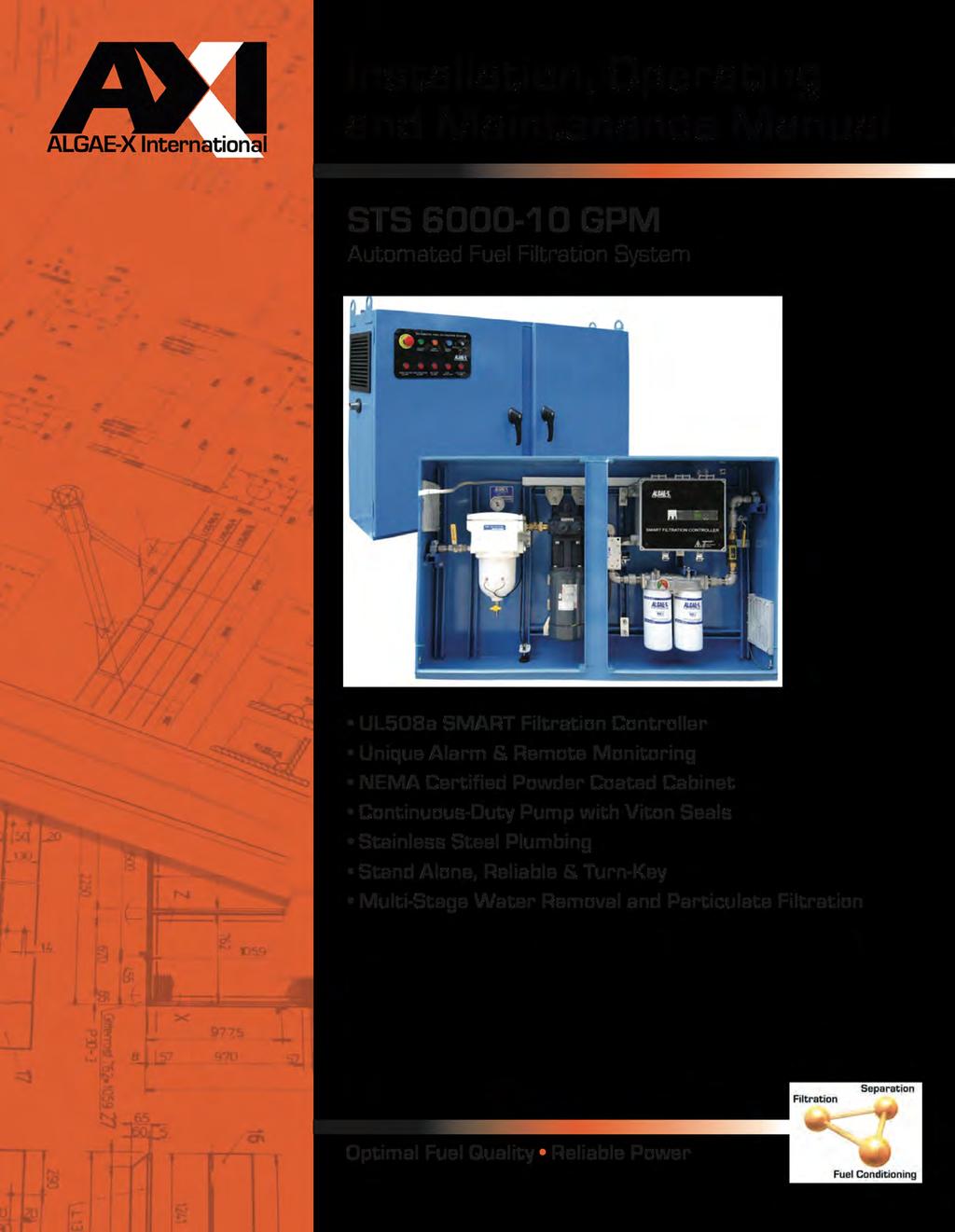
4 Programmable Automated Fuel Filtration System STS GPM Programmable Automated Fuel Filtration Systems are self-contained, stand-alone systems that remove and prevent the buildup of water, sludge and contaminants in tanks. They stabilize diesel and bio-fuels, eliminate microbial contamination to optimize and maintain fuel quality. STS systems guarantee Optimal Fuel Quality for Reliable Power at All Times. The STS 6000 Series feature: Multi-stage water removal and particulate filtration NEMA 12, 13, 4 Powder Coated or Stainless UL508A SMART Filtration Controller Unique Alarm Functions and Remote Monitoring Integrates with Building Management Systems Stainless Steel Plumbing Stand-Alone, Reliable & Turn-Key For safe operation, the STS GPM triggers automatic alarms and shuts down the pump when filters need service; a leak is detected; high separator water level, high filter vacuum, or high pump pressure occurs; or when the fuel flow is out of range. Preventive Maintenance Plans for mission-critical power are essential. However, most service agreements do not cover fuel-related engine failures. Fuel has a limited shelflife and even fresh fuel could contain water, sediment, microbes and bio-fuel components upon delivery. Periodic generator tests-runs are too short to determine if fuel quality is adequate for the demands of continuous, full-load operation. In fact, generator test runs significantly accelerate the fuel polymerization and degradation process by returning fuel that has been compromised by heat and pressure back to the tank. Potential liabilities can easily be avoided by implementing an AXI Fuel Quality Maintenance Program as part of every disaster recovery plan. An STS GPM automatically maintains fuel quality and guarantees reliable emergency power whenever it is needed. STS GPM SPECIFICATIONS Flow Rate Primary Filter/Water Separator/Coalescer Secondary Filter/ Water Block 10 GPM 10 or 30 µ Fine Filter or 60 µ SS Screen 10 µ Fine Filter 3 µ Water Block Fuel Conditioner LG-X 3000 Smart Filtration SFC-10G Controller Pump Power Plumbing Ports Weatherproof Cabinet Internal Gear Pump 110V 60Hz 20A or 230V 50Hz 15A Stainless Steel In 1 NPT Out 1 NPT NEMA 12, 13, 4 Powder Coat or Stainless Dimensions 37 x 60 x 12 (94 x 152 x 30 cm) Weight 400 lbs Not for use with fluids that have a flash point below 100 F. Wherever fuel is being used or stored Toll Free vernon@dieselfueltech.com Phone: +61 (0) STS GPM (11/11)


5 The system is automatically operated by the programmable UL508A SMART Filtration Controller. All components and control devices are contained within a fully enclosed, lockable, weatherproof, NEMA-rated cabinet. The principal components are a continuous-duty motor with coupled gear pump, a strainer/primary coalescing filter with vacuum sensor and gauge, an ALGAE-X Fuel Conditioner and a secondary water block fine filter with pressure gauge and sensor. The SEPAR primary filter protects the pump, coalesces and removes water and particulate. The patented ALGAE-X Fuel Conditioner prevents and reverses fuel degradation, agglomerization and microbial contamination. The secondary filter is a quick-change spin-on filter designed to remove dissolved and emulsified water and contaminants down to 1 µ. Implementing STS Fuel Quality Optimization & Maintenance Systems guarantee Optimal Fuel Quality for Reliable Power At All Times. STS GPM System prevents downtime, periodic tank cleaning, replacing out-of-spec fuel and fuelquality related injection system repairs. Typical installation of the STS Automatic Filtration System From Tank (Suction) Inside the STS GPM 1. Fuel Inlet (From Tank) 2. Inlet Ball Valve 3. Separ Primary Filter / Water Separator 4. Vacuum Gauge 5. Drain Valve (push and turn open) 6. Man. Air Vent / Bleed Screw 7. Vacuum Switch 8. ALGAE-X Smart Filtration Controller 9. Pressure Relief Valve 10. Gear Pump 11. Motor 12. ALGAE-X Magnetic Fuel Conditioner 13. Secondary Filter 14. Pressure Switch 15. Pressure Gauge 16. Outlet Ball Valve 17. Fuel Outlet (To Tank) 18. Mechanical Flow Meter with Flow Switch 19. Leak Detector (Float Switch) in Spill Tray STS GPM Accessories: Multiple tank functions AFC-705 Fuel Catalyst Digital Flow Meter Foot Valve Wide range of filter elements To Tank (Discharge) Wherever fuel is being used or stored 5
 4) Vacuum Gauge 14) Pressure Switch (behind post) 5) Drain Valve (push and turn open) 15) Pressure Gauge 6) Man.")
6 OVERVIEW BASIC SYSTEM COMPONENTS 1) Fuel Inlet (From Tank) 11) Motor 2) Inlet Ball Valve 12) ALGAE-X Magnetic Fuel Conditioner 3) Separ Primary Filter / Water Separator 13) Secondary Filters (two in parallel) 4) Vacuum Gauge 14) Pressure Switch (behind post) 5) Drain Valve (push and turn open) 15) Pressure Gauge 6) Man. Air Vent / Bleed Screw 16) Outlet Ball Valve 7) Vacuum Switch 17) Fuel Outlet (To Tank) 8) ALGAE-X Smart Filtration Controller 18) Mechanical Flow Meter with Flow Switch 9) Pressure Relief Valve 19) Leak Detector (Float Switch) in Spill Tray 10) Gear Pump 6
7 GENERAL SPECIFICATIONS STS GPM Flow Rate gpm / 600 gph 4,800 Gallons per 8 hour shift 14,400 Gallons per 24 hours Outline Dimensions (Enclosure) x 60 x 12 (H x W x D) System Weight... approx. 400 lbs Operating Temperature to 104 F; 5 to 40 C Electrical V / 60 Hz / single phase (standard) V / 50 Hz also available Pump... Gear Pump Suction capability (primed) ft vertical or 100 ft. horizontal lift (lines >1, primed) Motor... 1 hp single phase, continuous duty Timer... Programmable Digital Timer Inlet... 1 NPT male port Outlet... 1 NPT male port Max. Fluid Viscosity... 5 cst Note: The STS 6000 is designed to meet environmental standards for safe operation. (NOT for use with fluids that have a flash point below 100 F (38 C), e.g.: gasoline, alcohol, ) SYSTEM COMPONENTS CONTROL AND SAFETY DEVICES Algae-X Smart Filtration Controller in electrical sub enclosure UL 508A listed Industrial Control Panel Programmable Digital Timer Memory backup to retain program memory during power outages Pump control switch (Auto-Off-Manual), weatherproof, key operated Alarm Reset - weatherproof push button Power available indicator Pump running indicator External remote shut-down feature Inlet and outlet shut off ball valves Emergency stop button Pressure relieve valve Leak sensor and alarm indicator (system shutdown) Primary filter / water separator high vacuum alarm indicator and system shutdown (vacuum sensor) Primary filter / water separator high water alarm indicator and system shutdown (water sensor) Secondary filter high pressure alarm indicator and system shutdown (pressure sensor) Flow meter with no flow alarm indicator and system shutdown (flow switch) Pump motor starter with single-pole circuit breaker, contactor and overload relay PUMP / MOTOR: Positive displacement gear pump Relief valve Motor UL listed TEFC (Totally enclosed fan cooled) 7
8 PRIMARY FILTER / WATER SEPARATOR SEPAR fuel filter with water separator Drain valve on the bottom Analog vacuum gauge Back flushable 30-micron filter cartridge (other filter elements available) FUEL CONDITIONER Inline Algae-X Fuel Conditioner eliminates and prevents microbial contamination and the formation of sediments that naturally occur in diesel fuel. SECONDARY FILTER Two 3 Micron water blocking spin on filter (other filter elements available) Pressure gauge (stainless steel, liquid filled) WEATHERPROOF DOUBLE DOOR WALL-MOUNTED ENCLOSURE WITH LOCKABLE HANDLES / LATCHES 14-gauge steel construction with continuously welded seams Concealed hinges Finished in polyester powder coat inside and out over phosphatized surfaces Spill tray with leak detection Louvered side panels Brackets for wall mounting Literature pocket STAINLESS STEEL PLUMBING PRIMARY INSPECTION Upon arrival, the STS GPM Automatic Fuel Filtration System and accessories must be visually inspected before installation. Improper handling during shipping may cause physical or electrical problems. Immediately report or note any damages (also concealed ones) to the shipper. CHECKLIST: If the packing crate shows signs of damage inspect the STS-6000 cabinet for damage. Check the entire outside of the cabinet for damage that could indicate internal mechanical or electrical problems. Check locking handles, door and hinge operation. Check pump/motor hardware and all plumbing connections for tightness. Check all electrical terminals and connections for tightness. 8
9 INSTALLATION! IMPORTANT! It is recommended that only qualified, experienced personnel, familiar with this type of equipment, who have read and understood all the instructions in this manual should install, operate and maintain the system. MOUNTING The STS-6000 is a totally enclosed system and should be permanently wall mounted on a hard, level surface. Use provided mounting feet for proper fastening. This weatherproof unit is designed for wellventilated indoor or outdoor use within specified temperature range and should be located as close to the tank as possible. Please allow about 1 ft of space between the side louvers of the enclosure and nearby objects. This space is necessary to ensure sufficient ventilation of cooling air for the system and motor. ELECTRICAL! WARNING! To avoid the risk of electric shock make sure that the power supply to the system is disconnected and ensure that the system is at zero volts, before working on any of the system s electrical parts. Make sure that the systems power requirements and rated voltage / frequency match your electrical system (See wiring diagram). The STS 6000 may only be connected to properly grounded power sources for operator safety. Connect all components to the ground studs provided as shown on the electrical drawings.! WARNING! The whole system (Enclosure, doors, plumbing, motor, electric sub panel) must be properly grounded for operator safety. Depending on length of run, use copper wiring according to specification in wiring diagram and connect system to a separate UL listed breaker (not included) appropriate for branch circuit protection. Note: Wiring and electrical installation must be in accordance with all applicable Federal, State and Local rules, laws, standards and regulations. Remote Pump Shut-Down Feature: If required, connect the external pump shut down input terminal (see wiring diagram) and follow the specifications provided in the electrical wiring diagram to disable pump (e.g.: remote shut down, remote pump control, ). Please note that the contact needs to be supplied with +24V DC from the power supply of the STS 6000 Algae-X Smart Filtration Controller. Remote Monitoring - Dry Contacts: The STS provides two NO (normally open) dry contacts for remote alarm monitoring. Please see wiring diagram for contact rating, connection and location. 1) Summary Alarm dry alarm contact for high vacuum, high pressure or water detection (as well as Emergency stop and overload relay triggered) 2) Leak Detection dry alarm contact for leak detection 9
10 PLUMBING Use proper quality approved fuel line materials with at least 1 inner diameter on the suction side from the tank and at least 1 inner diameter on the return / discharge side back to the tank. Note: Do not put any stress on plumbing of STS 6000 and use a backing wrench when connecting the external plumbing. Where possible, use FLEXIBLE CONNECTIONS TO PREVENT STRESS caused by thermal expansion or plumbing misalignment. The pick-up tube/line(s) should originate from the lowest point of the tank (to remove all water), should be connected directly to the system s PUMP INLET SUPPLY FROM TANK port located on the left hand side of the enclosure and kept as short as possible. It is recommended to install an oversized, low restriction foot valve to keep the system primed, especially if the PUMP INLET SUPPLY FROM TANK port of the system is located above the lowest possible fuel level in the tank. A priming tee should be installed on the highest point of the suction line to be able to easily prime the lines and system. The return line(s) should be plumbed to the PUMP OUTLET RETURN TO TANK port (on the right side of the system) and enter the tank as far as possible from the pick up tube close to the tank bottom. A (swing) check valve may be required on the return line(s) on some installations to prevent back flow pressure. Multiple suction and/or return lines may be connected to a manifold outside the STS-6000 (see options list). Anti-Siphon or other external plumbing devices may be required please check local regulations code. The system capabilities are 15 ft suction (vertical) or 100 ft horizontal lift, when connected to piping of 1 ID or more with no additional flow restrictions such as valves, 90-degree connectors or other plumbing accessories. For continuous optimal performance, make sure suction and discharge lines are free and that nothing is blocking the flow of fuel and that the suction line always stays primed. Note: Plumbing and Installation must be in accordance with all applicable Federal, State and Local rules, laws, standards and regulations.
11 TYPICAL PLUMBING / ABOVE GROUND TANK INSTALLATION (SCHEMATICALLY) IMPORTANT INSTALLATION PRECAUTIONS The suction line of the system should be independent and separate from the suction line of the engine. If that is not possible, appropriate valves must be installed to completely separate the STS-6000 from the engine fuel system to prevent any possible interference with safe engine operation. It is highly recommended to plumb the discharge line independent and separate of the engine s fuel return line back to the tank. If the return line from the engine and the discharge of the STS 6000 have to be combined in any way, adequate valves should be installed to prevent any possible interference with safe engine operation. Note: If any of the STS 6000 system s fuel lines are used in combination with the engine s fuel system, the STS 6000 should be disabled during engine operation (use the provided remote pump shut down feature as shown in the electrical drawing and described above).
12 PRIMING THE SYSTEM The pump supplied with the STS 6000 is NOT automatically self-priming and must not be run dry.! WARNING! If the pump is allowed to run without fuel, pump damage will occur. The pump head of the STS 6000 unit is shipped from the factory filled with Diesel #2 to facilitate initial lubrication. This will not eliminate the necessity to prime the complete system. The STS 6000 is primed by using the externally installed priming tee (not provided) on the suction side of the system. Also the primary filter as well as the suction line has to be completely filled with fuel prior to the initial system start-up. PRIMING PROCEDURE: 1. Ensure the pump is filled with #2 Diesel fuel. 2. Ensure that the inlet ball valve is in the open and the outlet ball valve is in the closed position. 3. Slightly open the manual air vent valve (bleed screw) located inside the STS 6000 (position #6 page 5). 4. Open the externally installed priming tee (located at the highest point of the suction plumbing), fill the line with fuel until fuel escapes from bleed screw (manual air vent), close the manual air vent, continue filling until all air is bled from the plumbing lines and system, close the priming tee. (for tanks situated on a lower level than the STS 6000, it is recommended that a foot valve is installed at the fuel tank to hold the fuel column). 5. Make sure to completely fill suction line to its highest point with fuel (no trapped air), in particular when the suction line exits the tank top and the STS 6000 is located below that level. 6. Open the outlet ball valve and ensure the inlet ball valve is also in open position. 7. Switch on the pump and observe fuel flow. The system is equipped with a vacuum gauge on the input side of the pump. The gauge should read 0 to 11" HG vacuum maximum under normal conditions. Vacuum gauge readings reaching 12" HG vacuum indicate excessive debris in the primary filter/ water separator (or a flow restriction or too high suction height and therefore pressure drop in the suction line) and will result in pump shutdown and activate the alarm HIGH VACUUM ALARM. Note: 12" HG vacuum = clogged primary filter or suction line flow restriction / excessive lift. The system s pressure gauge on the secondary filter should show 25 PSI maximum pressure under normal conditions (.433 PSI = 1' vertical head pressure). Pressure gauge readings in excess of 25 PSI pressure indicate excessive filter, or fuel line restrictions and/or friction. System pressure over 25 PSI indicates a high-pressure failure ( HIGH PRESSURE ALARM indicator) and will automatically shut down the pump. The pressure relief valve has a PSI set point. System pressure in excess of PSI will cause the pressure relief valve to open and vent fuel back to the fuel transfer pump inlet side. 12
13 SMART FILTRATION CONTROLLER - ALARM FEATURES The STS 6000 is equipped with an Algae-X Smart Filtration Controller. System and alarm status are displayed on the industrial control panel (on the door) via indicator lights and on the text display directly on the controller. If all red indicator alarm lights are illuminated please see the text display for further info. One of the two situations will be present: 1) Emergency stop button depressed (Unlock E-Stop button by turning and push ALARM RESET button to return to normal operation. 2) Motor overload relay (OLR) tripped. Remove front panel of Smart Filtration Controller and push reset button on OLR relay, close panel again and push ALARM RESET button on door panel to return to resume operation. Note: All red indicator lights on the control panel illuminated at the same time indicates that either the Emergency stop button has been pressed or that the motor overload relay has been tripped. INITIAL START-UP / COMMISSIONING CHECKLIST FLOW SWITCH SETTING / ADJUSTMENT ( NO FLOW ALARM ) Note: Flow switch needs to be adjusted to actual flow rate for proper system operation. Please make sure system is properly primed and check when pump running for a steady stream of fuel without air bubbles in the mechanical flow meter (indicator) inside the STS 6000 enclosure. If the NO FLOW ALARM alarm light is blinking (and after 10 seconds illuminate continuously as the pump is turned off) the flow switch located on the side of the mechanical flow meter needs to be adjusted to the actual flow rate. This can be easily done by sliding the black switch (with the wires attached) located on the side of the sight glass carefully up or down (while pump is running) and lining up the flow switch with the indicator ring inside the sight tube of the flow meter showing the actual flow rate. For further information please see enclosed instruction sheet. You can reset the alarm by pushing the ALARM RESET button located on the control panel. GAUGE VENTING / ACCURACY After shipment, pointer of gauges may not rest at zero due to internal case pressure buildup caused by temperature variations. Accuracy may be significantly reduced. To restore gauge to operating condition, move yellow lever of fill plug to the open position or remove small plug from top of gauge and leave open. 13
14 INITIAL TEST PROCEDURE With breakers and power turned on and pump running check all alarms for proper operation: 1. Manually raise float switch located in drip/spill tray. Pump should immediately turn off and LEAK DETECTION should illuminate. Reset alarm by pushing the RESET ALARM button on the control panel. 2. Slowly partially close inlet ball valve. At 12 HG pump should turn off and HIGH VACUUM ALARM should illuminate. Open inlet ball valve again. Reset alarm by pushing the RESET ALARM button. 3. Slowly partially close outlet ball valve. At 25 PSI pump should turn off (after a delay of about 1 second) and HIGH PRESSURE ALARM should illuminate. Open outlet ball valve again reset alarm by pushing the RESET ALARM button. 4. Slide the flow switch located on the side of the mechanical flow meter slightly upwards away from the flow indicator inside the sight tube (mark original position before doing so). The NO FLOW ALARM indicator should start blinking for 10 seconds and then illuminate constantly as the pump is turned off. Slide flow switch back into original position and reset alarm by pushing the RESET ALARM button. Note: If any of the above described alarm test procedures fail or if any alarm trip value deviates immediately contact Algae-X International. OPERATION! WARNING! Do not use with gasoline. This System is not meant for use with gasoline nor with other flammable liquids having a flash point less than 100 F. Use with gasoline or use with any flammable liquids at a temperature exceeding their flash point, presents an immediate explosion and fire hazard.! WARNING! Never use the STS 6000 at a temperature exceeding the flash point of its contents. EMERGENCY STOP Note: In case of an emergency the pump can be turned off and disabled by depressing the red EMERGENCY STOP button on the control panel. To release the EMERGENCY STOP button located on the control panel turn the red knob in the direction indicated by the arrows on the mushroom button and push the ALARM RESET button to acknowledge. PUMP OPERATION Apply control power to unit. Place breakers in the Algae-X Smart Filtration Controller in the ON position. Automatic: Place the key switch in the AUTO position. When the timer contacts close, the pump will start and run until the timer setting has expired. Manual (Override): Place the key switch in the RUN position. The pump motor will run until the switch is returned to the OFF or AUTO mode positions or till an alarm or overload has been tripped.
15 PROGRAMMING THE TIMER The programmable timer is part of the Micro PLC settings of the Algae-X Smart Filtration Controller located inside the STS 6000 system. Note: The PLC uses military time all times programmed must be in that format. 1. Please make sure the Emergency Stop button is not engaged, the key switch set to OFF and push the ALARM RESET button on the control panel. 2. When power is first applied to the system the display of the PLC will show (blinking) date and time. 3. We will now set current date and time (must be in military format): 4. Hit the ESC button 5. Select Stop and press OK 6. Select Yes (use down arrow key) and press OK 7. Select Setup (use down arrow key)and press OK 8. Select Clock and press OK 9. Select Set Clock and press OK 10. Using the arrow keys set current day of the week, time and date as indicated in the display and press OK ( or to change value, or to change between week day, time and date). 11. When finished entering press OK to confirm 12. Press ESC 13. Select Start and press OK correct time and date should be displayed 14. We are now ready to program the timer (military time format must be used): 15. Hit the ESC button 16. Select Set Param (use down arrow key) and press OK 17. Push down arrow key till Timer 1 is displayed 18. Press OK 19. Use left and right arrow keys to select the day/days of the week the system should automatically turn on and the up or down arrow key to activate the selected day. 20. Use arrow keys in same manner to program the On time when the system will switch on (on the selected day/days) 21. Use arrow keys in same manner to program the Off time when the system will switch off (on the selected day/days) 22. Press OK to confirm entry when finished 23. If required you can set up to 3 Timers by using the up and down arrow key 24. Press ESC twice to return back to the time and date display Please call Algae-X International with any questions. FUEL LINE LEAK If fuel is detected in the spill / drip tray, the float switch will activate the fuel leak alarm illuminating the LEAK DETECTION indicator. The pump motor will shut off and remain locked out of operation until the leak has been corrected and the ALARM RESET button has been pushed. Before removing the spilled fuel from the basin, turn the key switch to the OFF position. Always make sure to find the cause of the leakage and correct it. After removing the spilled fuel, allowing the leak switch to return to its normal position, the key switch can be returned to the AUTO or RUN mode. 15
16 Note: Disposal of fuel and associated waste should be done in accordance with Federal, State and Local regulations. STABILIZING AND OPTIMIZING FUEL QUALITY We recommend treating the fuel with the ALGAE-X Fuel Catalyst (AFC-705). This will enhance and accelerate the tank cleaning process by breaking down and dissolving existing tank sludge. AFC-705 will decontaminate compartments of the tank that are out of reach of the suction line. Depending on the condition of the fuel and the amount of sludge build-up, it is recommended to initially use a double dose of one to twenty-five hundred (1:2500) instead of one to five thousand (1:5000) This has proven to be essential in accelerating the tank cleaning process. AFC-705 contains detergent, surfactant, dispersant, corrosion inhibitor, lubricity enhancer and combustion catalyst. It does not contain biocides. AFC-705 should always be used periodically in particular to stabilize fuel that is stored for longer periods of time. Note: In cases of severe tank contaminant build-up (sludge) and high water level in bottom, it is recommended to clean the tank (vacuum bottom) and polish the fuel before initial use of an STS system. MAINTENANCE! IMPORTANT! It is recommended that only qualified, experienced personnel, familiar with this equipment, who have read and understood all the instructions in this manual should install, operate and maintain the system.! IMPORTANT! Always disconnect the system from the electric power supply before working or servicing it. Do not proceed with any maintenance unless the pressure or vacuum has been released, the system has been allowed to reach ambient temperature and all fluids have been drained. PREVENTATIVE MAINTENANCE The STS-6000 Automatic Fuel Filtration System should be visually inspected and tested a minimum of every six months according to the procedure below during light duty cycles. Monthly inspections are recommended for systems that are being used in excess of an average of 8 hours day and five days a week. Prior to performing the maintenance procedure ensure that: 1. The electrical sub-panel mounted main disconnect switch is operating properly, 2. the user supplied remote circuit breaker is in the Off position, and 3. that all sources of power are isolated from the unit. 4. Proceed only after this has been verified and properly tagged. Drain visible water and sediment from primary filter / water separator (see Servicing Primary Filter / Water Separator below). Check enclosure and all parts for corrosion and rust. Check locking latches, door and hinge operation. Check cabinet mounting hardware. Tighten as necessary. Check pump/motor hardware for tightness. Pump/motor hardware will loosen after normal operation due to vibration. This hardware is lock nutted, check all bolts for secure nuts. Check all electrical terminals and connections for tightness. 16
17 All motors are permanently lubricated and do not require any lubrication. All pumps are self-lubricating and do not require any maintenance. Check all plumbing joints for leaks. Tighten fittings and joints as necessary. Remove accumulated fuel in drip tray as necessary. Inspect all filters and separators. See section below on filter inspection and service. With breakers and power turned on again and pump running check all alarms for proper operation: 1. Manually raise float switch located in drip/spill tray. Pump should immediately turn off and LEAK DETECTION should illuminate. Reset alarm by pushing the RESET ALARM button on the control panel. 2. Slowly partially close inlet ball valve. At 12 HG pump should turn off and HIGH VACUUM ALARM should illuminate. Open inlet ball valve again. Reset alarm by pushing the RESET ALARM button. 3. Slowly partially close outlet ball valve. At 25 PSI pump should turn off (after a delay of about 1 second) and HIGH PRESSURE ALARM should illuminate. Open outlet ball valve again Reset alarm by pushing the RESET ALARM button. 4. Slide the flow switch located on the side of the mechanical flow meter slightly upwards away from the flow indicator inside the sight tube (mark original position before doing so). The NO FLOW ALARM indicator should start blinking for 10 seconds and then illuminate constantly as the pump is turned off. Slide flow switch back into original position and reset alarm by pushing the RESET ALARM button. Note: If any of the above described alarm test procedures fail or if any alarm trip value deviates immediately contact Algae-X International. Note: All filter elements should be replaced at least every six months. SERVICING PRIMARY FILTER Set the telltale gauge pressure indicator (red pointer) to slightly above the black needle prior to operation. The gauge will indicate maximum vacuum pressure during system operation. Clogging filter elements restrict the flow of fuel and the system s vacuum gauge will indicate a pressure drop. The gauge is mounted on top of the primary filter. At a pressure drop of 12 HG, the pump will automatically shut off and activate the HIGH VACUUM ALARM indicator light. The signal indicates that it is time to either back-flush or change the filter element. Servicing and back-flushing primary filter: 1. Turn key switch to the OFF position make sure pump will not turn on 2. Close the inlet and outlet ball valve 3. Open the brass colored bleed screw at the top of the filter cover 4. Place a fuel waste container below the yellow safety drain valve on the bottom of the filter bowl 5. Open the yellow safety drain valve (push & turn counter clockwise) 6. Close after approximately 2 seconds 7. After approximately 10 seconds reopen the drain valve 8. Close after visible sediment, particles and water have been drained from the bowl 9. Prime the filter by removing the cover (4 wing bolts) and pouring clean diesel fuel into the filter body until the fuel level reaches the top of the filter body 17
18 10. Replace the lid. Note: Evenly tighten the wing bolts to ensure a good seal 11. Close bleed screw on top of the lid 12. Open the inlet and outlet ball valve 13. Push the ALARM RESET button on the control panel to acknowledge the alarm and reset it 14. Return the pump selector key switch to AUTO or RUN 15. Check for leaks when re-starting and pressurizing the system. Your system is now ready to resume normal operation Note: Elements can be back-flushed up to 5 times before replacement is required SERVICING WATER SEPARATOR If the water level in the primary filter/water separator reaches a certain level in the bowl, the water sensor will trigger the alarm HIGH WATER ALARM and shut off the pump. The signal indicates that it is time to drain the bowl on the water separator. Draining water from the primary filter/water separator: 1. Turn key switch to the OFF position make sure pump will not turn on 2. Close the inlet and outlet ball valve 3. Open the brass colored bleed screw on the top of the filter cover 4. Place a fuel waste container below the yellow safety drain valve on the bottom of the filter bowl 5. Open the yellow safety drain valve (push & turn counter clockwise) 6. Close after approximately 2 seconds 7. After approximately 10 seconds, reopen the drain valve 8. Close after visible sediment, particles and water have been drained from the separator 9. Prime the filter by removing the cover (4 wing bolts) and pouring clean diesel fuel into the filter body until the fuel level reaches the top of the filter body 10. Replace the lid. Note: Evenly tighten the wing bolts to ensure a good seal 11. Close bleed screw on top of the lid 12. Open the inlet and outlet ball valve 13. Push the ALARM RESET button on the control panel to acknowledge the alarm and reset it 14. Return the pump selector key switch to AUTO or RUN 15. Check for leaks when re-starting and pressurizing the system. Your system is now ready to resume normal operation SERVICING SECONDARY FILTERS Clogging filter elements and saturation of the water block filters restrict the flow of fuel and the system s pressure gauge will indicate a pressure drop. The gauge and differential pressure indicator are mounted on top of the secondary filter head. At a pressure drop of 25 PSI (red dial area of the gauge) the pump will automatically shut off and activate the HIGH PRESSURE ALARM indicator light. The signal indicates that it is time to change the filter elements. There are several types of Algae-X spin on fine filters available; we recommend using the WB-3 (3 micron water block fine filter). The Algae-X Water Block incorporates polymer technology to remove emulsified water from fuel. Changing the secondary filters: 18
19 Note: Both secondary spin on filters need to be replaced at the same time. Always use two of same type filter elements never mix two different kinds or micron ratings. 1. Turn key switch to the OFF position make sure pump will not turn on 2. Close the inlet and outlet ball valve 3. Place an appropriate container underneath the filters 4. Remove both old spin on filters with the provided filter wrench by turning the cartridge counter clock wise seen from the bottom of the cartridge 5. Apply a film of lubricating oil to the gasket of the new filters. Screw the new filter canisters to the filter head until the gasket is tight and secure (an additional ½ to one turn after the filter makes contact with the gasket) 6. Open the inlet and outlet ball valve 7. Push the ALARM RESET button on the control panel to acknowledge the alarm and reset it 8. Return the pump selector key switch to AUTO or RUN 9. Check for leaks when re-starting and pressurizing the system 10. Your system is now ready to resume normal operation Note: Disposal of fuel, associated waste and filters should be done in accordance with Federal, State and Local regulations.! WARNING! Some fuels may have been treated with biocides. Biocides are extremely toxic and may enter the body through the skin. It is recommended to use adequate protection and proper precautions if fuel contains biocide type products.
20 TROUBLESHOOTING No fuel delivery 1. Pump does not run 2. Pump is not primed 3. Fuel supply line blocked 4. Excessive lift 5. Air leak in fuel supply to pump 6. Pump rotation direction incorrect 7. Intake or outlet valve closed 8. Check valve installed backwards Insufficient fuel delivered 1. Air leak at inlet 2. Defective pressure relief valve or check valve 3. Excessive lift 4. Pump worn 5. Inoperative foot valve 6. Piping improperly installed or dimensioned 7. Primary filter/water separator plugged Rapid pump wear 1. Pipe strain on pump causing bind 2. Worn pump/motor coupler 3. Pump has been run dry or with insufficient fuel 4. Plumbing on inlet side not appropriately dimensioned Alarm HIGH VACUUM ALARM comes on with clean or new filter element installed 1. Heavily contaminated fuel / excessive water in tank 2. Restriction in plumbing on inlet side too high 3. Excessive lift 4. Inoperative foot valve 5. Inlet ball valve not fully open 6. Suction line clogged Alarm HIGH PRESSURE ALARM comes on with clean or new filter elements installed 1. Heavily contaminated fuel / excessive water in tank 2. Restriction in plumbing on discharge side too high 3. Head (lift) on discharge side too high 4. Check valve stuck or defective 5. Outlet ball valve not fully open 6. Discharge line clogged Pump requires too much power 1. Air in plumbing lines 2. Liquid too viscous 3. Bent pump shaft, binding rotor 20
21 Noisy operation 1. Insufficient fuel supply 2. Air leaks in the inlet pipe 3. Air or gas in fuel on the suction side 4. Worn out spider coupling 5. Pump coupler out of balance Pump requires frequent re-priming 1. Inoperative foot valve 2. Inoperative check valve 3. Inoperative solenoid valve (optional) 4. Pump cavitations 5. Plumbing air leaks 6. Lift too high 7. Leaking pump seal Motor does not turn or turns intermittently 1. Control power not available 2. Motor thermal overload condition 3. Pump failed and seized 4. Motor failure 5. Emergency Button depressed Pump leaks fuel 1. Loose pump plumbing fittings 2. Worn pump shaft seal 3. Pump pressure relief valve failure 4. Fuel leak elsewhere and fuel dripping or running towards the pump 5. Excessive head from overhead storage tank 6. Worn pump O-rings or seals 21
22 AUTOMATIC FUEL FILTRATION SYSTEMS WARRANTY LIMITED WARRANTY ALGAE-X International makes every effort to assure that its products meet high quality and durability standards and expressly warrants the products described herein, against defects in material and workmanship for a period of one (1) year from the date of purchase. This warranty is not intended to supplant normal inspection, care and service of the products covered by the user, and shall not obligate ALGAE-X to provide free service during the warranty period to correct breakage, maladjustment or other difficulties arising out of abuse, misuse, or improper care and maintenance of such products. Our express warranty is subject to the following terms and conditions: 1. This warranty shall only extend to and is only for the benefit of original purchasers who use the products covered hereby 2. Any warranty claim received by ALGAE-X after one (1) year from the date of purchase will not be honored even if it is claimed that the defect occurred prior to one (1) year from the date of purchase. 3. This warranty shall not apply to products (1) which have been tampered with, altered or repaired by anyone other than ALGAE-X without the express prior written consent of ALGAE-X (2) which have been installed improperly or subject to misuse, abuse, accident, negligence of others, improper operation or maintenance, neglect or modification, or (3) which have had the serial number altered, defaced or removed. 4. The liability of ALGAE-X under this warranty is limited to the repair or replacement of the defective product. ALGAE-X assumes NO LIABILITY for labor charges or other costs incurred by any purchaser incidental to the service, adjustment, repair, return, removal or replacement of products. ALGAE-X ASSUMES NO LIABILITY FOR ANY GENERAL, SPECIAL, INCIDENTAL, CONSEQUENTIAL, CONTINGENT OR OTHER DAMAGES UNDER ANY WARRANTY, EXPRESS OR IMPLIED, AND ALL SUCH LIABILITY IS HEREBY EXPRESSLY EXCLUDED. 5. ALGAE-X MAKES NO WARRANTIES, EXPRESS OR IMPLIED, OF MERCHANTABILITY, FITNESS FOR A PARTICULAR PURPOSE OR OTHERWISE, WITH RESPECT TO THE PRODUCTS COVERED BY THIS WARRANTY POLICY, EXCEPT AS EXPRESSLY PROVIDED FOR HEREIN. NO EMPLOYEE, AGENT, REPRESENTATIVE OR DISTRIBUTOR IS AUTHORIZED TO MAKE ANY WARRANTY ON BEHALF OF ALGAE-X OTHER THAN THE EXPRESS WARRANTY PROVIDED FOR HEREIN. 6. ALGAE-X reserves the right at any time to make changes in the design, material, function and specifications of its products. Any such changes shall not obligate ALGAE-X to make similar changes in such products that were previously manufactured. WARRANTY CLAIM PROCEDURE To make a claim under this warranty, please call our ALGAE-X at (239) or (877) , and provide: Name and location where unit was purchased, the date and receipt of purchase, model number, serial number, and a detailed explanation of the problem you are experiencing. The Customer Service Representative may, at the discretion of ALGAE-X, arrange for a Field Engineer to inspect your system. If the inspection discloses a defect covered by its limited warranty, ALGAE- X will either repair or replace the defective parts or products. ALGAE-X assumes no liability, if upon inspection, ALGAE-X or its representative determines that there is no defect or that the damage to the system resulted from causes not within the scope of this limited warranty. For service and sales, please contact ALGAE-X : 24
23 APPENDIX A - ABBREVIATIONS USED IN THIS MANUAL Abbreviations of terms used with STS 6000 Automatic Fuel Filtration Systems. When following a drawing utilize this guide to define abbreviated system and component names. This is a master list. The drawings and text pertaining to your equipment may not contain all these terms. AC Alternating Current AHR Alarm Horn Relay AH Alarm Horn BPRV Back Pressure Regulating Valve BRK Motor/Pump Bracket BV Ball Valve C Contactor CB Circuit Breaker CSR Check Strainer Relay CV Check Valve DC Direct Current DPDT Double Pole Double Throw F Fuse FLWS Flow switch FS Float switch GA Gauge GAL Gallons GPM Gallons Per Minute HFL High Fuel Level Relay HG Mercury HP Horsepower HZ Hertz I.D. Inside Diameter JB Junction Box HG Inches of Mercury L Lamp L.E.D. Light Emitting Diode LFF Loss of Flow Relay LFL Low Fuel Level Relay LPR Low Pressure Relay MDB Main Distribution Block MDS Main Disconnect Switch MOT Motor N.C. Normally Closed NEC National Electric Code NEMA National Electric Manufacturers Assoc. N.O. Normally Open NP Nameplate NPT National Pipe Thread O.D. Outside Diameter OLR Over Load Relay OPT Option PCB Printed Circuit Board PCRX Pump Control Relays PG Pressure Gauge PLR Pipe Leak Relay PRV Pressure Relief Valve PRS Pressure Switch PS Power Supply PSI Pounds Per Square Inch PSR Pressure Switch Relay PRR Pump Running Relay SC Swing Check Valve SOL Solenoid TB Terminal Block T Control Transformer TDR Time Delay Relay TEFC Totally Enclosed, Fan Cooled THR Tank Heater Control Relay TS Transducer Pressure Switch V Voltage VAC Voltage, Alternating Current VDC Voltage, Direct Current VG Vacuum Gauge
24 APPENDIX B DRAWINGS 26
25
Phone: +61 (0)
") www.dieselfueltech.com Email: vernon@dieselfueltech.com Phone: +61 (0) 419 795 676 INSTALLATION, OPERATING AND MAINTENANCE MANUAL TABLE OF CONTENTS OVERVIEW BASIC SYSTEM COMPONENTS... 6 GENERAL SPECIFICATIONS...
www.dieselfueltech.com Email: vernon@dieselfueltech.com Phone: +61 (0) 419 795 676 INSTALLATION, OPERATING AND MAINTENANCE MANUAL TABLE OF CONTENTS OVERVIEW BASIC SYSTEM COMPONENTS... 6 GENERAL SPECIFICATIONS...
FPS-500 / FPS 750. Fuel Polishing System. Installation and Operating Manual
 FPS-500 / FPS 750 Fuel Polishing System Eliminates Microbial Contamination Installation and Operating Manual Stabilizes Fuel Removes Water & Sludge Prevents Tank Sediments Improves Engine Reliability Optimizes
Installation, Operating and Maintenance Manual
 . Installation, Operating and Maintenance Manual TK 240 Tank Cleaning and Fuel Restoration System www.dieselfueltech.com Email: vernon@dieselfueltech.com Phone: +61 (0) 419 795 676 1 www.dieselfueltech.com
FPS-500. Fuel Polishing System Eliminates Microbial Contamination. Operating Manual
 FPS-500 Fuel Polishing System Eliminates Microbial Contamination Operating Manual Stabilizes Fuel Removes Water & Sludge Prevents Tank Sediments Improves Engine Reliability Optimizes Fuel Quality Optimal
INSTALLATION, OPERATING AND MAINTENANCE MANUAL
 2 INSTALLATION, OPERATING AND MAINTENANCE MANUAL TABLE OF CONTENTS OVERVIEW BASIC SYSTEM COMPONENTS... 6 GENERAL SPECIFICATIONS... 7 system components... 7 PRIMARY INSPECTION...8 Installation... 8 Mounting...8
STS GPM. Fuel Conditioning and Filtration System. Installation, Operating and Maintenance Manual
 STS 5000-10GPM Fuel Conditioning and Filtration System Installation, Operating and Maintenance Manual Improves Engine Reliability Removes Water & Sludge Prevents Tank Sediments Optimizes Fuel Quality Stabilizes
Installation, Operating and Maintenance Manual
 Installation, Operating and Maintenance Manual STS 7030 Automated Fuel Filtration System INSTALLATION, OPERATING AND MAINTENANCE MANUAL TABLE OF CONTENTS GENERAL SPECIFICATIONS... 8 STS 7030...8 SYSTEM
Phone: +61 (0)
") .. 2 OPERATING AND MAINTENANCE MANUAL TABLE OF CONTENTS OPERATING AND MAINTENANCE MANUAL... 3 TABLE OF CONTENTS... 3 INITIAL INSPECTION... 7 OVERVIEW - Mobile Tank Cleaning System... 7 TANK CLEANING -
.. 2 OPERATING AND MAINTENANCE MANUAL TABLE OF CONTENTS OPERATING AND MAINTENANCE MANUAL... 3 TABLE OF CONTENTS... 3 INITIAL INSPECTION... 7 OVERVIEW - Mobile Tank Cleaning System... 7 TANK CLEANING -
Phone: +61 (0)
") . 2 INSTALLATION, OPERATING AND MAINTENANCE MANUAL TABLE OF CONTENTS INITIAL INSPECTION... 6 OVERVIEW - MOBILE TANK CLEANING SYSTEM... 6 TANK CLEANING - WHY, WHERE AND HOW... 7 GENERAL TANK CLEANING PROCEDURE...
. 2 INSTALLATION, OPERATING AND MAINTENANCE MANUAL TABLE OF CONTENTS INITIAL INSPECTION... 6 OVERVIEW - MOBILE TANK CLEANING SYSTEM... 6 TANK CLEANING - WHY, WHERE AND HOW... 7 GENERAL TANK CLEANING PROCEDURE...
FPS- 80. Manual. Reverso Pumps, Inc. Ph: (954)
") FPS- 80 Manual Table of Contents System Overview... 1 Control Panel Overview... 2 Technical Specifications... 3 Electrical and Installation... Tank Diagrams... 5 Initial Setup... 6 Digital Timer Instructions:
FPS- 80 Manual Table of Contents System Overview... 1 Control Panel Overview... 2 Technical Specifications... 3 Electrical and Installation... Tank Diagrams... 5 Initial Setup... 6 Digital Timer Instructions:
MTC- INSTRUCTION, OPERATING, AND MAINTENANCE MANUAL Tank Cleaning and Fuel Restoration System
 MTC- INSTRUCTION, OPERATING, AND MAINTENANCE MANUAL Tank Cleaning and Fuel Restoration System 1.239.690.9589 1.877.425.4239 Toll Free www.axi-international.com AXI.International AXInternational AXIFuel
Installation and Operations Manual
 Installation and Operations Manual Automated Fuel Maintenance System MODEL FTI-2.8 FUEL TECHNOLOGIES INTERNATIONAL 03/01/2011 Rev B - Fuel Technologies - FTI-2.8 OPERATIONS & MAINTENANCE CONTENTS Installation
Installation and Maintenance Manual
 Installation and Maintenance Manual Automated Fuel Maintenance System FTI-2.8 FUEL TECHNOLOGIES INTERNATIONAL 01/01/2014 Rev A - Fuel Technologies - FTI-2.8 with ModBus OPERATIONS & MAINTENANCE CONTENTS
MTC-500/1000/3000. Mobile Tank Cleaning System. Operating & Maintenance Manual. Optimal Fuel Quality Provides Peak Engine Performance
 MTC-500/1000/3000 Mobile Tank Cleaning System Removes Water & Sludge Optimizes Fuel Quality Improves Engine Reliability Operating & Maintenance Manual MTC-1000 MTC-3000 Optimal Fuel Quality Provides Peak
STS SERIES. Enclosed Automated Fuel Maintenance Systems (STS)
") STS SERIES Enclosed Automated Fuel Maintenance Systems (STS) AXI s Enclosed Automated Fuel Maintenance Systems are programmable and automated self-contained, stand-alone fuel filtration, separation, and
STS SERIES Enclosed Automated Fuel Maintenance Systems (STS) AXI s Enclosed Automated Fuel Maintenance Systems are programmable and automated self-contained, stand-alone fuel filtration, separation, and
SPS PACKAGED PUMPSET WITH PLC DAY TANK CONTROL PANEL September 2011
 SPS PACKAGED PUMPSET WITH PLC DAY TANK CONTROL PANEL September 2011 SPS Packaged Pumpset with PLC Day Tank Control Panel page 1 of 12 Contents DESCRIPTION... 2 PRIMARY INSPECTION... 2 INSTALLATION... 2
Maintenance Manual. Automated Fuel Maintenance System FTI-5A SINGLE TANK FUEL TECHNOLOGIES INTERNATIONAL
 Maintenance Manual Automated Fuel Maintenance System FTI-5A SINGLE TANK FUEL TECHNOLOGIES INTERNATIONAL 05/01/2016 Rev A Fuel Technologies FTI-5A Single Tank Maintenance Section FTI - Fuel Maintenance
MTC HC-50 INSTALLATION, OPERATING, AND MAINTENANCE MANUAL
 MTC HC-50 INSTALLATION, OPERATING, AND MAINTENANCE MANUAL High Capacity Mobile Tank Cleaning, Fuel Optimization, and Transfer System 1.239.690.9589 1.877.425.4239 Toll Free www.axi-international.com AXI.International
Maintenance Manual WITH ONE SUBMERSIBLE PUMP. Automated Fuel Maintenance System FTI-5A FUEL TECHNOLOGIES INTERNATIONAL LLC
 Maintenance Manual WITH ONE SUBMERSIBLE PUMP Automated Fuel Maintenance System FTI-5A FUEL TECHNOLOGIES INTERNATIONAL LLC Replacement Manuals Available on Website: www.fueltechnologiesinternational.com
SMARTPUMP MANUAL. with Touchscreen - April 2012
 SMARTPUMP MANUAL with Touchscreen - April 2012 FUEL SUPPLY SYSTEM MANUAL with Touchscreen SmartPump page 1 of 21 Contents DESCRIPTION... 2 INSTALLATION... 2 INITIAL START-UP TEST PROCEDURES... 4 OPERATION...
PACKAGED PUMP SET & SKID PUMP SET MANUAL
 ON PUMP 1 LEAD BOTH PUMP 2 LEAD DUPLEX MODE FUEL TRANSFER SYSTEM PUMP 1 RUNNING FUEL LINE LEAK WARNING: PUMP 2 RUNNING BOTH PUMP 1 LEAD PUMP 2 LEAD DUPLEX MODE FUEL LINE LEAK FUEL TRANSFER SYSTEM PUMP
MTC HC-90 INSTALLATION, OPERATING, AND MAINTENANCE MANUAL
 MTC HC-90 INSTALLATION, OPERATING, AND MAINTENANCE MANUAL High Capacity Mobile Tank Cleaning, Fuel Optimization, and Transfer System 1.239.690.9589 1.877.425.4239 Toll Free www.axi-international.com AXI.International
Maintenance Manual. Automated. Fuel Maintenance System FTI-5A. FUEL TECHNOLOGIES INTERNATIONAL LLC
 Maintenance Manual Automated Fuel Maintenance System FTI-5A FUEL TECHNOLOGIES INTERNATIONAL LLC www.fueltechnologiesinternational.com 03/01/2011 - Fuel Technologies FTI-5A Maintenance Section FTI - Fuel
TC-9 FUEL FILL COMMANDER & TC-25 TANK COMMANDER March 2012
 TC-9 FUEL FILL COMMANDER & TC-25 TANK COMMANDER March 2012 TC-9 Fuel Fill Commander page 1 of 22 Contents TC-9 FUEL FILL COMMANDER... 2 Description... 2 Installation... 3 Sequence Of Operation... 6 TC-25
Fuel Catalyst AFC-705 / AFC-805
 Fuel Catalyst AFC-705 / AFC-805 ALGAE-X Fuel Catalyst is a powerful full spectrum additive and tank cleaning agent. It provides superior fuel quality for engines and storage tanks, lowering operating cost,
Installation Manual FTI-10A & FTI-20A SINGLE TANK. Automated Fuel Maintenance System FUEL TECHNOLOGIES INTERNATIONAL
 Installation Manual Automated Fuel Maintenance System FTI-10A & FTI-20A SINGLE TANK FUEL TECHNOLOGIES INTERNATIONAL 05/01/2016 Rev A Fuel Technologies FTI-10A & FTI-20A Single Tank Installation Manual
Packaged Design Day Tank Systems
 Fuel Supply Systems Packaged Design Day Tank Systems for diesel/fuel oil application providing a reliable fuel source for diesel and turbine engine driven equipment and oil fired boilers model & accessory
AFP Manual. Automatic Fuel Polishing System, 600 GPH. Shown with optional enclosure and stand
 AFP- 600 Manual Automatic Fuel Polishing System, 600 GPH Shown with optional enclosure and stand Table of Contents Description... 3 5-Stage Primary Filtration... 4 System Overview... 5 Control Panel Overview...
CLEAN ROOM DEVICES, LLC "WHERE TUBING AND FITTINGS COME TOGETHER"
 CLEAN ROOM DEVICES, LLC "WHERE TUBING AND FITTINGS COME TOGETHER" CRD600AF Automatic Fitting Inserter With Auto Feed OPERATIONS MANUAL (Shown with optional alcohol dispenser) 1 VERSION 1.1 LAST EDITED
Installation Manual. Automated Fuel Maintenance System FTI-5A FUEL TECHNOLOGIES INTERNATIONAL
 Installation Manual Automated Fuel Maintenance System FTI-5A FUEL TECHNOLOGIES INTERNATIONAL Replacement Manuals Available on Website: www.fueltechnologiesinternational.com 07/15/2015 Rev E Fuel Technologies
ESE Series Cast Iron Sewage Pumps
 Owner s Manual ESE Series Cast Iron Sewage Pumps TABLE OF CONTENTS General Safety.................... 2 Specifications..................... 3 Installation.................... 4 & 5 Troubleshooting...................
CLEAN ROOM DEVICES, LLC "WHERE TUBING AND FITTINGS COME TOGETHER"
 CLEAN ROOM DEVICES, LLC "WHERE TUBING AND FITTINGS COME TOGETHER" CRD600 Automatic Fitting Inserter OPERATIONS MANUAL VERSION 2.1 LAST EDITED 7.25.14 DOCUMENT NUMBER 001 cleanroomdevices.com 1 Table of
GENERAL SPECIFICATIONS FOR:
 GENERAL SPECIFICATIONS FOR: FUEL FILTRATION SYSTEMS 5A, 8A, 10A, 15A, 20A, 30A, &40A Equipment manufactured in the U.S.A. All specifications subject to change. Version 3.1 5A MODEL GENERAL SPECIFICATIONS
PRYCO, INC. P. O. BOX 108 Mechanicsburg, IL OPERATIONS AND MAINTENANCE MANUAL For PUMP SETS
 PRYCO, INC. P. O. BOX 108 Mechanicsburg, IL 62545 Telephone: 217 / 364-4467 Fax: 217 / 364-4494 OPERATIONS AND MAINTENANCE MANUAL For PUMP SETS WHAT TO DO FIRST Upon receiving your new pump set system
Advantage-D. Operating Instructions and Maintenance Manual. Central Vacuum Systems (Expandable/Modular Models) (Ver.
 (Ver.") Advantage-D Series 3 Central Vacuum Systems (Expandable/Modular Models) (Ver. 8/05) Operating Instructions and Maintenance Manual DESCRIPTION The Becker Advantage-D and Advantage-L central vacuum systems
Advantage-D Series 3 Central Vacuum Systems (Expandable/Modular Models) (Ver. 8/05) Operating Instructions and Maintenance Manual DESCRIPTION The Becker Advantage-D and Advantage-L central vacuum systems
Updated: October 2012
 T: (630) 794-5100 EMERGENCY POWER FUEL SYSTEMS Earthsafe Systems, Inc. 7320 S. Madison Willowbrook, IL 60527 F: (630) 794-5106 info@earthsafe.com www.earthsafe.com Updated: October 2012 The information
Val-Matic Air / Oil Hydraulic Panel Pump Control System. Operation, Maintenance and Installation Manual
 Manual No. 5AOP-OM1-2 Val-Matic Air / Oil Hydraulic Panel Pump Control System Operation, Maintenance and Installation Manual INTRODUCTION... 1 RECEIVING AND STORAGE... 1 DESCRIPTION OF OPERATION... 1 INSTALLATION...
TECHNICAL PAPER 1002 FT. WORTH, TEXAS REPORT X ORDER
 I. REFERENCE: 1 30 [1] Snow Engineering Co. Drawing 80504 Sheet 21, Hydraulic Schematic [2] Snow Engineering Co. Drawing 60445, Sheet 21 Control Logic Flow Chart [3] Snow Engineering Co. Drawing 80577,
NECO Pumping Systems
 INSTALLATION OPERATION & MAINTENANCE INSTRUCTIONS For Your NECO Pumping Systems PACKAGED CIRCULATING SYSTEM THIS COMPLETELY ASSEMBLED, TESTED, PACKAGED CIRCULATING SYSTEM IS OF THE HIGHEST QUALITY AND
SST & SRS DAY TANK MANUAL. July 2014
 SST & SRS DAY TANK MANUAL July 2014 SST & SRS DAY TANK MANUAL page 1 of 25 Contents INSTALLATION... 2 Vent Openings... 5 Siphon-Drain... 7 Day Tank Pump Priming Procedure (Required)... 8 DAY TANK OPERATION...
Low Profile J Series Power Unit with Vane Pump
 Low Profile J Series Power Unit with Vane Pump READ ALL INSTRUCTIONS CAREFULLY BEFORE ATTEMPTING TO ASSEMBLE, INSTALL, OPERATE OR MAINTAIN THE PRODUCT DESCRIBED. PROTECT YOURSELF AND OTHERS BY OBSERVING
Model and Series 115 VAC INDUSTRIAL DIAPHRAGM PUMPS. PumpAgents.com - buy pumps and parts online INDUSTRIAL DIAPHRAGM PUMPS
 Model 31801 and 31800 Series 115 VAC INDUSTRIAL DIAPHRAGM PUMPS INDUSTRIAL DIAPHRAGM PUMPS FEATURES Run Dry Ability Self-Priming Thermal Overload Protected Motor Easy Installation Low Amp Draw Compact
Self Cleaning Hood System Installation, Operation, and Maintenance Manual
 Self Cleaning Hood System Installation, Operation, and Maintenance Manual RECEIVING AND INSPECTION Upon receiving unit, check for any interior and exterior damage, and if found, report it immediately to
CRD600 Automatic Fitting Inserter
 CRD600 Automatic Fitting Inserter OPERATIONS MANUAL VERSION 2.3 LAST EDITED 12.07.2018 cleanroomdevices.com 1 Table of Contents Title Page.. 1 Table of Contents. 2 1.0 General Product & Safety Information...3
PENBERTHY MODELS GL AND GH GAS OPERATED JET PUMPS INSTALLATION, OPERATION AND MAINTENANCE INSTRUCTIONS
 Before installation, these instructions must be read carefully and understood. PRODUCT WARRANTY Emerson warrants its Penberthy products as designed and manufactured to be free of defects in the material
DODGE COOL LUBE 2 for Sleevoil Pillow Blocks Part Numbers , , ,
 DODGE COOL LUBE for Sleevoil Pillow Blocks Part s 063487, 063488, 07889, 07890 These instructions must be read thoroughly before installing or operating this product. WARNING: To ensure the drive is not
CRD610 Automatic Fitting Inserter
 CRD610 Automatic Fitting Inserter OPERATIONS MANUAL VERSION 1.2 LAST EDITED 12.12.2018 cleanroomdevices.com 1 Table of Contents Title Page. 1 Table of Contents...2 1.0 General Product & Safety Information....3
QUALITY MISTING PUMPS
 DIRECT DRIVE TOTALLY ENCLOSED FAN COOLED 60200KH, 60201KH MISTING PUMP MANUAL INCLUDING: SPECIFICATION DATA, GENERAL SAFETY PRECAUTIONS, OPERATION, INSTALLATION, PARTS, MAINTENANCE & WARRANTY QUALITY MISTING
PowerFLO 7800 Series 12 Volt DC Motor-Driven Diaphragm Pumps
 Installation Operation Repair Parts PowerFLO 7800 Series 12 Volt DC Motor-Driven Diaphragm Pumps Specifications Motor Type: 12 VDC, permanent magnet, totally enclosed, non-ventilated Leads: 14 AWG, 12
ValveMate 7000 Controller Operating Manual
 A NORDSON COMPANY ValveMate 7000 Controller Operating Manual Steady Test Clear Time Set Fast Slow POWER RUN SETUP CYCLE A NORDSON COMPANY VALVEMATE 7000 Run Setup Purge Program Fast Slow Time Set Pressure
NECO Pumping Systems
 INSTALLATION OPERATION & MAINTENANCE INSTRUCTIONS For Your NECO Pumping Systems Fuel Oil Transfer System THIS COMPLETELY ASSEMBLED, TESTED, PACKAGED SYSTEM IS OF THE HIGHEST QUALITY AND DESIGN. TO OBTAIN
INSTRUCTION MANUAL INSTALLATION, OPERATION, AND MAINTENANCE ACTUATOR MANIFOLD
 INSTRUCTION MANUAL INSTALLATION, OPERATION, AND MAINTENANCE B-3724M ACTUATOR MANIFOLD MIDLAND MANUFACTURING CORP. 7733 Gross Point Road Skokie, Illinois 60077 Phone (847) 677-0333 FAX (847) 677-0138 WEBSITE
Model AM2 M40 Panel Installation, Operation, and Maintenance Manual
 Model AM2 M40 Panel Installation, Operation, and Maintenance Manual RECEIVING AND INSPECTION Upon receiving unit, check for any interior and exterior damage, and if found, report it immediately to the
Operation & Service Manual
 Operation & Service Manual Model: 5010 Hydraulic Power Unit 05/2004 - Rev. 01 Includes Illustrated Parts Lists 1740 Eber Rd Tronair, Inc. Phone: (419) 866-6301 Holland, OH 43528-9794 www.tronair.com 800-426-6301
Compact LTC Oil Filtration System Manual
 INSTRUCTION MANUAL Compact LTC Oil Filtration System Manual COMPACT LTC OFS-MANUAL 1.4 READ AND UNDERSTAND THIS MANUAL PRIOR TO OPERATING OR SERVICING THIS PRODUCT. TABLE OF CONTENTS General System Description
OFX7 Operating Maintenance and Troubleshooting Manual L-4219
 OFX7 Operating Maintenance and Troubleshooting Manual L-4219 L-2999 Created 9.2012 User Manual OFX7 L-4219 - Table of Contents - Preface. 4 Customer Service. 4 Modifications to the Product 4 Warranty.
Operating and Installation Instructions
 Model Number 40401-c (-sp) Electronic Fuel Pump Operating and Installation Instructions This Product is Patent Pending. Application available upon request CAUTION! This product is to be installed only
Operator's Manual. Storage System. Ultrasound Probe Cabinet. Manufactured by:
 Storage System Ultrasound Probe Cabinet Operator's Manual Manufactured by: CIVCO Medical Solutions 102 First Street South Kalona, IA 52247 USA 319.248.6757 / 800.445.6741 WWW.CIVCO.COM Copyright 2018 All
2009 PRICE LIST. Prices FOB Ft. Myers, FL. Effective May 15, Subject to change without notice Suggested MODEL PORT SIZE HP RANGE
 2009 PRICE LIST Prices FOB Ft. Myers, FL. Effective May 15, 2009. Subject to change without notice. INLINE FUEL CONDITIONER 2009 Suggested MODEL PORT SIZE HP RANGE US Retail Price LG-X 200 1/4" NPT or
Automated Fuel Maintenance Systems (FPS)
") FPS SERIES Automatic Alerts Pump Shut Down When Filters Need Service Leak Detection Water Detection High Pump Vacuum High Pump Pressure Compact Design Modular Controls Racor Filters Multi-stage Water Removal
FPS SERIES Automatic Alerts Pump Shut Down When Filters Need Service Leak Detection Water Detection High Pump Vacuum High Pump Pressure Compact Design Modular Controls Racor Filters Multi-stage Water Removal
Operator s Safety and Service Manual
 !! Operator s Safety and Service Manual Cordless Sprayer Model: C100WO SMK Industries Inc 12839 Carpenter Trail Carlisle. IA 50047 Phone: 515-202-0052 Email: john@smksprayers.com Web: www.smksprayers.com
Model &
 PumpAgents.com - Click here for Pricing/Ordering Model 31765-0092 & 31765-0094 Dual Sensor Max VSD WATER PRESSURE SYSTEM AUTOMATIC TWO STAGE WATER SYSTEM WITH PUMPGARD STRAINERS IDEAL FOR PLEASURE AND
007 Tank Monitor. WARNING Never use with gasoline or highly flammable liquids.
 Model #7575 Recommended Installation, Maintenance and Inspection Instructions 007 Tank Monitor 7575 Important safety instructions - save these instructions in a readily accessible location. WARNING Never
APCO ASR-400/450 SEWAGE AIR RELEASE VALVES
 APCO ASR-400/450 SEWAGE AIR RELEASE VALVES Instruction D12005 December 2012 Instructions These instructions provide installation, operation and maintenance information for the APCO ASR- 400/450 Sewage
QUALITY MISTING PUMPS
 TOTALLY ENCLOSED DIRECT DRIVE 60030KH, 60031KH, 60050KH, 60051KH 60100KH, 60101KH, 60150KH, 60151KH MISTING PUMP MANUAL INCLUDING: SPECIFICATION DATA, GENERAL SAFETY PRECAUTIONS, OPERATION, INSTALLATION,
Positive Displacement Pump
 www.conairgroup.com U S E R G U I D E UGC028-1105 Positive Displacement Pump Models PD 3. 5, 7.5, 10, 15 and 25 Corporate Office: 724.584.5500 l Instant Access 24/7 (Parts and Service): 800.458.1960 l
Installation Operation & Maintenance Manual. Oil-Free (Dry) Rotary Vane Vacuum Pump Systems
 Rotary Vane Vacuum Pump Systems") Installation Operation & Maintenance Manual Oil-Free (Dry) Rotary Vane Vacuum Pump Systems Part No. 9983-0000-S07 / November 2018 OIL-FREE (DRY) ROTARY VANE VACUUM PUMP SYSTEMS TABLE OF CONTENTS CUSTOMER
Installation Operation & Maintenance Manual Oil-Free (Dry) Rotary Vane Vacuum Pump Systems Part No. 9983-0000-S07 / November 2018 OIL-FREE (DRY) ROTARY VANE VACUUM PUMP SYSTEMS TABLE OF CONTENTS CUSTOMER
WARCO CHEMAG SERIES GH FILTERS
 WARCO CHEMAG SERIES GH FILTERS High Performance Pleated & Bag Type Filtration Systems INSTALLATION, OPERATION, AND MAINTENANCE INSTRUCTIONS Thank you for your purchase of a WARCO Series GH Filtration System.
Matala. VersiFlow Series. Instruction and Maintenance Manual
 VersiFlow Series High Flow Multi-Purpose "Versatile " Pump V-3200 1/5HP 150W / Discharge 2 V-3900 1/3HP 250W / Discharge 2 V-4700 1/2HP 400W / Discharge 2 V-5600 1HP 750W / Discharge 2 Instruction and
25 GALLON PORTABLE OIL LIFT
 25 GALLON PORTABLE OIL LIFT Model 92859 SET UP AND OPERATING INSTRUCTIONS Diagrams within this manual may not be drawn proportionally. Due to continuing improvements, actual product may differ slightly
Warning and Safety Precautions
 EXPRESS WARRANTY AND DISCLAIMER OF IMPLIED WARRANTIES Lily Corporation unconditionally guarantees its products to be free of defects in material or workmanship and further warrants that, for a period of
Installation & Operation Manual. IMPORTANT: This manual contains important information. READ AND KEEP FOR REFERENCE.
 Elecronic Preset Meter 2 Industrial Handheld Series Model EPM2-IND Standard Series IMPORTANT: This manual contains important information. READ AND KEEP FOR REFERENCE. IOM-139-02-EN (1-12) 53400-139 Rev.
Motorized Stainless 2-Way Valves
 Installation and Operation Manual Motorized Stainless 2-Way Valves Safety Valve ETV Applications WARNING This Heat-Timer valve is strictly an operating valve; it should never be used as a primary limit
Operators Manual. Recirculating Chiller /06/08
 Operators Manual Recirculating Chiller 110-197 11/06/08 Table of Contents Section 1. General Information 1.1 Warranty 1.2 Unpacking 1.3 Package Contents 1.4 Description of the Recirculating Chiller 1.5
READ THIS MANUAL CAREFULLY BEFORE USING THE PUMP
 OWNER S MANUAL Pond Pump READ THIS MANUAL CAREFULLY BEFORE USING THE PUMP Important Notice: This manual contains important information about the installation, operation and safe use of this product. This
HALLMARK INDUSTRIES INC
 Performance Part No. HP. CONVERTIBLE JET PUMP USER S MANUAL GPH of Water @ Total Discharge Pressure of 40 psi Max. Pressure Max suction (shallow well) Max Suction (deep well) Max GPM (@0 head) Max Discharge
MODEL 10LH SPECIFICATION
 MODEL 10LH SPECIFICATION 1.0 General Specifications There will be furnished one (1) only Grind Hog TM Model 10LH Comminutor as manufactured by G.E.T. Industries, Inc. Rotation shall be in a clockwise (standard)
PowerFLO 5800/5900 Series
 PowerFLO 5800/5900 Series 5830/5930: 3.0 GPM 5836/5936: 3.6 GPM Inches (mm) Bypass Models Demand Models Switch 1.87 (47.5) 7.58 (192.5) 7.58 (192.5) 9.08 (230.6) 5840/5940: 4.0 GPM 5850/5950: 5.0 GPM Inches
Installation Manual. Automated Fuel. Maintenance. System FUEL TECHNOLOGIES INTERNATIONAL LLC
 Installation Manual Automated Fuel Maintenance System FTI-10A & FTI-20A FUEL TECHNOLOGIES INTERNATIONAL LLC Replacement Manuals Available on Website: www.fueltechnologiesinternational.com 03/01/2011 -
TP300 INDUSTRIAL TRASH PUMP OPERATOR S MANUAL
 TP300 INDUSTRIAL TRASH PUMP OPERATOR S MANUAL IT IS EXTREMELY IMPORTANT TO READ AND UNDERSTAND THE ENTIRE CONTENTS OF THIS OPERATOR S MANUAL BEFORE ATTEMPTING TO OPERATE THE PRODUCT. THIS EQUIPMENT IS
GLYCOL FEED SYSTEMS OPERATION & MAINTENANCE MANUAL
 GLYCOL FEED SYSTEMS OPERATION & MAINTENANCE MANUAL PLEASE RECORD THE FOLLOWING DATA (Information is located on the product label or packing slip) Model Number: Date Code: Installation Date: Installation
Variable Speed Misting Pump Totally Enclosed Direct Drive MODEL HDE-1PH-230VFD
 Variable Speed Misting Pump Totally Enclosed Direct Drive MODEL 60100-HDE-1PH-230VFD SAFETY, GENERAL INFORMATION, ELECTRICAL DEFINITIONS WARNING CAN cause DEATH, SEVERE INJURY or substantial property damage.
PT-516 Pumping Trap Installation and Maintenance
 PT-516 Pumping Trap Installation and Maintenance IB-104-B This bulletin should be used by experienced personnel as a guide to the installation and maintenance of the PT-516 Pumping Trap or Pumping Trap
END SUCTION CENTRIFUGAL PUMPS
 OWNERS GUIDE TO INSTALLATION AND OPERATION FW000 009 Supersedes 07 END SUCTION CENTRIFUGAL PUMPS READ THESE INSTRUCTIONS CAREFULLY Read these installation instructions in detail before installing your
ARKAL SCREEN LINE H - SERIES Hydraulically Operated Self-Cleaning Screen Filter SERVICE & MAINTENANCE MANUAL
 ARKAL SCREEN LINE H - SERIES Hydraulically Operated Self-Cleaning Screen Filter SERVICE & MAINTENANCE MANUAL Table of Contents Subject Page No. Introduction... 2 Safety Instructions... 3 Description &
Instruction Bulletin. Jockey Pump Controller
 Instruction Bulletin Jockey Pump Controller Installation Start Up Service This instruction bulletin is a guide for personnel involved with maintenance, engineering and approval of Fire Pump equipment and
OPERATING INSTRUCTIONS PLEASE READ CAREFULLY
 OPERATING INSTRUCTIONS PLEASE READ CAREFULLY 925-0330 Rev 0 0416 TABLE OF CONTENTS SAFETY SUMMARY... 3 SPECIFICATIONS... 4 1.0 INTRODUCTION/DESCRIPTION.... 5 2.0 LOCATION AND MOUNTING... 5 3.0 CONNECTIONS
MicroCoat System Operating Manual MC4000 Series MC785M, MC785M-WF Spray Valves
 MicroCoat System Operating Manual MC Series MC785M, MC785M-WF Spray Valves A NORDSON COMPANY Introduction The MicroCoat System provides precise lubrication control for metal stamping operations. The MC
Packaged Pump Sets FOR DIESEL FUEL OIL APPLICATION. Packaged Pump Sets for Diesel/Fuel Oil Application Page 1
 Packaged Pump Sets for Diesel/Fuel Oil Application Page 1 Packaged Pump Sets FOR DIESEL FUEL OIL APPLICATION Packaged Pump Sets for Diesel/Fuel Oil Application Page 2 Description Simplex SPS Series Packaged
Manual Concentrate Management System
 Form 887 05/15 Manual Concentrate Management System with Automatic Flush INSTALLATION AND OPERATION MANUAL Unit Serial Number All quality FoamPro products are ruggedly designed, accurately machined, carefully
Dodge Cool Lube 2 for Sleevoil Pillow Blocks Part Numbers , , ,
 Dodge Cool Lube for Sleevoil Pillow Blocks Part Numbers 063487, 063488, 07889, 07890 These instructions must be read thoroughly before installation or operation. This instruction manual was accurate at
A2P Single Phase Automatic Industrial Battery Charger
 A2P Single Phase Automatic Industrial Battery Charger Featuring 205B Konrad Cres., Markham, ON, L3R 8T9 www.chargers.ca Building Canada s toughest battery chargers for over a century. Congratulations on
GARDEN HOSE UTILITY PUMP
 GARDEN HOSE UTILITY PUMP MODEL #HPP360, HPP12V, 473707 MODEL #HPP360, 473707 MODEL #HPP12V ATTACH YOUR RECEIPT HERE Purchase Date SAFETY INFORMATION Please read and understand this entire manual before
XCITE Owner s Manual. Reso-not TM Damping System XCITE 1502C HYDRAULIC POWER SUPPLY
 Reso-not TM Damping System XCITE Owner s Manual 1502C HYDRAULIC POWER SUPPLY Xcite Systems Corporation 675 Cincinnati RDS Batavia - 1 Pike Cincinnati, Ohio 45245 Tel: (239) 980-9093 Fax: (239) 985-0074
PARTS AND INSTALLATION MANUAL
 PSP-3240 POLYPROPYLENE SELF-PRIMING 2 CENTRIFUGAL PUMP PARTS AND INSTALLATION MANUAL PSP-3240 Shown with GX-160 Honda CDS-JOHN BLUE COMPANY DIVISION OF ADVANCED SYSTEMS TECHNOLOGY, INC. 165 Electronics
ACC Series Power Conditioner OPERATION & INSTALLATION MANUAL
 ACC Series Power Conditioner OPERATION & INSTALLATION MANUAL PHASETEC digital power conditioners are designed to safely operate electrical equipment in the harshest power quality environments. With a wide
GeyserMax-Flow Series
 GeyserMax-Flow Series 115V/60Hz Waterfall Pump GM-3900 1/5HP 150W / Discharge 1-1/2 GM-4700 1/3HP 250W / Discharge 2 GM-5400 1/2HP 400W / Discharge 2 GM-6200 3/4HP 750W / Discharge 2 230V/50Hz GM-3800
Pump Installation and Service Manual HRS Hydromatic Retractable System
 Pump Installation and Service Manual HRS Hydromatic Retractable System NOTE! To the installer: Please make sure you provide this manual to the owner of the pumping equipment or to the responsible party
Eurovacuum Installations and Operating manual EV Series Vacuum pumps Models
 Eurovacuum Installations and Operating manual EV Series Vacuum pumps Models 0010-0630 Single Stage Oil Sealed Rotary Vane Pump Eurovacuum EV Series Single Stage Oil Sealed Rotary Vane Pumps Eurovacuum
ProFlo FatBoy
 The Standard For Professional Grade Diaphragm Pumps. ProFlo 3300 5500 FatBoy Operational and Installation Guidelines, Repair & Parts Contents 3300 5500 Fatboy Operational and Installation Guidelines...2