Phone: +61 (0)
|
|
|
- Eugene Bennett
- 5 years ago
- Views:
Transcription


1 .
2 2
3 INSTALLATION, OPERATING AND MAINTENANCE MANUAL TABLE OF CONTENTS INITIAL INSPECTION... 6 OVERVIEW - MOBILE TANK CLEANING SYSTEM... 6 TANK CLEANING - WHY, WHERE AND HOW... 7 GENERAL TANK CLEANING PROCEDURE... 7 AFC-705 FUEL CATALYST... 8 AFTER CLEANING THE TANKS... 8 TANK CLEANING PREPARATIONS... 9 START UP PROCEDURE... 9 Priming the System...9 OPERATING PROCEDURE STEP BY STEP WE ARE NOW READY FOR FILTERS MTC 500 / 1000 / Changing Filters FILTERS MTC Servicing and Back-flushing the MTC-350 filter: MTC MAINTENANCE...14 Draining and Storing the System Pump Strainer / Y-Strainer (MTC-500) Fuel / Oil Separator / Coalescer Pump LG-X Fuel Conditioner Suction and Discharge hoses SAFETY NOTES TROUBLESHOOTING...16 TANK CLEANING SYSTEMS WARRANTY TECHNICAL ASSISTANCE AND ORDERING Replacement filter elements MTC-350 / 500 / 1000 / 3000 SYSTEM IDENTIFICATION
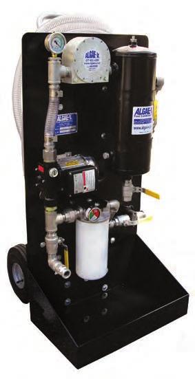
4 MTC 1000 LX Mobile Tank Cleaning System Mobile Tank Cleaning and Fuel Restoration Systems clean tanks while reconditioning, stabilizing and decontaminating diesel, biofuels, light oils and hydraulic fl uids. MTC systems remove water, sediment and sludge that naturally form and accumulate in tanks. They are compact, heavy-duty, multi-stage industrial systems for long-term reliable service. MTC systems clean tanks and restore fuel to its Clear & Bright pristine condition without the need for anyone to enter the tank. Mobile Tank Cleaning Systems feature: AXI s MTC Systems offer Three Stages of Fuel Conditioning Stage 1: Stage 2: Stage 3: The separator/coalescer removes water and particulate that clog fi lters and harm injectors. reversing the process of fuel deterioration and buildup of tank sludge. The industrial type water block fi ne fi lter removes emulsifi ed water and very fi ne solids down to 3 microns. duty aluminum cart. A clear suction hose and optional rotor sight glass show fuel fl ow and clarity. The large drip tray is designed to prevent spillage. Fuel can be polished without using any consumables by connecting the discharge hose MTC 1000 LX SPECIFICATIONS Flow Rate 900 GPH Separator Maintenance Free Centrifugal Water Separator/Coalescer Spin-on Final Filter 1, 3, 10 or 25 µ Fine Filter 3 or 10 µ Water Block Fuel Conditioner LG-X 3000 Pump Self priming rotary vane pump with integrated bypass valve & strainer Power 115V 60Hz 20A or 230V 50Hz 20A Ports 1 Cam & Groove Clear Suction Hose 1, 25 ft Discharge Hose 1, 25 ft Dimensions 48 x 22.5 x 25 (122 x 57 x 63 cm) Weight 160 lbs Not for use with fluids that have a flash point below 100 F. MTC 1000 LX Principal Components The principal components are a self-priming vane pump with integrated bypass valve and strainer, maintenance free centrifugal water separator/coalescer, spin-on fine filter and water block filters, MTC Options holding capacity to save time and accelerate the cleaning of tanks with large amounts of sludge, rust, scale and sediments. transportation. AFC-705 Fuel Catalyst is a broad-spectrum fuel additive concentrate that enhances the breakdown and removal of sludge, slime and bio-fouling from tank walls and baffles. Wherever fuel is being used or stored Toll Free vernon@dieselfueltech.com Phone: +61 (0) ALGAE-X International MTC 1000 LX (12/11)

5 INITIAL INSPECTION Congratulations on your purchase of an Algae-X MTC Mobile Tank Cleaning System! Upon delivery, the MTC System and accessories must be visually inspected. Shipping and handling may cause physical or electrical problems. Note any damages with the shipping company or refuse shipment in cases of severe damage. OVERVIEW - MOBILE TANK CLEANING SYSTEM The MTC is a three-stage mobile fuel conditioning and tank cleaning system. It efficiently removes sludge and water from fuel and oil tanks, restoring & optimizing fuel quality in the same operation. The system is designed as a fuel/oil dialysis system that circulates and cleans fuel/oil by pumping it from the tank, processing it through the MTC and back into the tank. The system can also be used to clean fuel or oil by pumping it from one tank through the MTC into another tank and / or suitable container. The MTC System processes fuel or oil by pumping it from the tank through the clear intake hose on Port 1, through the oil-water-sludge separator and then the Algae-X Fuel Conditioner. The discharge hose can be connected to either Port 2 or Port 3. Port 2 sends the fuel directly back to the tank, bypassing the filter. Port 3 sends the fuel through the water block / fine filter and then back to the tank. Ports 1, 2 and 3 are equipped with Quick Disconnect Couplings that easily connect to the matching couplings on suction and discharge hoses.
6 TANK CLEANING - WHY, WHERE AND HOW All storage tanks naturally accumulate water, solids and sludge resulting from condensation and the degradation of fuel and oil. The more fuel we turn over through a tank, the more debris and water will accumulate in the bottom. Algae-X Fuel Conditioning and Filtration Systems eliminate the need for costly, periodic manual tank cleaning, while stabilizing and extending the shelf life of fuel. This is extremely important for all applications of long-term fuel storage, especially emergency power generators. The Algae-X Mobile Tank Cleaning System is compact, easy to operate and extremely versatile. It is ideal for use: in marinas, to clean tanks on board of all types of vessels at construction sites in remote areas with on-site fuel storage for heavy equipment in service trucks maintaining standby generators in truck/vehicle depots in hydraulic oil tanks GENERAL TANK CLEANING PROCEDURE The MTC has three different operating modes providing the operator flexibility and efficiency. In Phase One, bulk water and sludge are removed from the tank into a separate container for disposal. In Phase One the fuel bypasses the filter. The Separator/ Coalescer and Algae-X Fuel Conditioner work in conjunction removing free water, sludge, and particulate, as small as 5 micron, from the tank. The system is not in a re-circulating mode. The fuel enters through Port 1 and exits through Port 2 into a separate waste container. Water and sludge are directly removed from the tank and collected in an appropriate container for disposal. In Phase Two, the MTC system is in recirculating mode, continuously restoring, reconditioning and returning the fuel back to the tank. Phase Two will continuously remove free water and particles as small as 5 micron using only the water separator and Algae-X Fuel Conditioner. The fuel enters in Port 1 and returns back to the tank from Port 2. The fuel bypasses the filter, which will economize on consumable filter elements. Phase two will restore the fuel to a clear and bright condition. In Phase Three, the MTC system is still in a recirculating mode. The fuel enters through Port 1 and exits through Port 3 back to the tank. In addition to the water separator and Algae-X Fuel Conditioner, this phase incorporates the water block / fine filter removing even invisible particles down to 3 micron, as well as entrained and emulsified water. Phase Three will restore the fuel to its optimal clear and bright condition. We always recommend keeping a before and after bottom tank sample for show & tell purposes and to demonstrate the improvement of fuel color, clarity and opacity. 7
7 AFC-705 FUEL CATALYST The use of Algae-X AFC-705 Fuel Catalyst is an essential part of any tank cleaning procedure, to more rapidly and efficiently decontaminate and clean the entire fuel system. The catalyst is best introduced into the process during Phase Two. Before dosing the tank with AFC- 705, remove as much of the sludge and free water as possible. Adding the Algae-X Fuel Catalyst (AFC-705) to the tank will speed up the cleaning process by breaking down and dissolving the sludge covering the tank walls and baffles. AFC-705 will decontaminate areas and sections of the tank that are out of reach of the suction hose. Using a higher concentration of one to twenty five hundred (1:2500) instead of one to five thousand (1:5000) has proven to be very helpful in accelerating the rate of dissolving the sludge. Even higher doses of AFC-705 may be necessary depending on contamination level of fuel. AFC-705 is a full spectrum fuel additive containing combustion catalyst, surfactant, detergent, dispersant, corrosion inhibitor, lubricity enhancers and fuel stabilizer that eliminates the need for expensive toxic biocides. AFTER CLEANING THE TANKS 1. Stabilize the Fuel AFC-705 should always be used to stabilize the fuel in tanks used for long-term fuel storage. When no Algae-X re-circulating system or STS Automatic Filtration System is in place, AFC-705 will maintain fuel quality and prevent formation of solids for six to twelve months. Added during the tank cleaning phase it is not necessary to use AFC-705 again for 6 months or more. 2. Prevent Water from Accumulating The use of Algae-X Water Eliminators will prevent water from accumulating in the tank. The water eliminators will absorb and remove any future water from condensation or other sources. Preventing water accumulation eliminates microbial growth and the need for toxic biocides. 3. Monitor Fuel Quality Liqui-Cult Fuel Test Kits are ideal to monitor your fuel supply for microbial contamination. The tests quantify bacterial and fungal activity. Algae-X Tank Cleaning Systems significantly lower operating costs, save fuel, eliminate periodic tank cleaning and the build up of solids, sludge and acids. Algae-X Technology enhances personnel safety and addresses environmental concerns by preventing the need for costly toxic biocides. Larger capacity Mobile and Stationary Tank Cleaning Systems are available. 8
8 TANK CLEANING 101! IMPORTANT! It is recommended that only qualified, experienced personnel, familiar with this equipment, who have read and understood all the instructions in this manual should operate and maintain the system.! WARNING! Do not use with gasoline, solvents, corrosive liquids, food liquids or other liquids having a flash point less than 100 F. Use with gasoline or use with any flammable liquids at a temperature exceeding their flash point, presents an immediate explosion and fire hazard! IMPORTANT! All safety measures and practices involving fuel / oil handling should be observed and followed at all times.! WARNING! For operator safety the MTC system needs to be connected to a properly grounded power source protected by a breaker and matching the electrical requirements of the pump (see pump label). NOTE: Contact factory for use of MTC with biodiesel, vegetable oil or other liquid compatibility. PREPARATIONS Before operating the MTC, we recommend you first determine the amount of contaminants, free water and sludge in the tank. Algae-X provides a variety of tank sampling equipment including Sampling Pumps, tubing and bottles as well as Sampling Thieves ( Bacon Bomb ) please see our FS Fluid Sampling line of products. Please make sure the samples are taken from the bottom of the tank (in the deepest spot). An old and tried method is also sticking the tank. This means using a stick with Kolor Kut paste on the end that reaches through the top all the way to the bottom of the tank. Kolor Kut paste will show the water level in the tank and indicate how much water and sludge will have to be removed. Call Algae-X for further information on other fuel sampling equipment. START UP PROCEDURE Note: The MTC System is equipped with a positive displacement vane pump. It should never be run dry and started without the hoses attached and/or valves in the closed position. Failure to do so may damage the bypass valve and / or pump. PRIMING THE SYSTEM Before turning on the pump make sure the entire suction side of the MTC system (suction hose, separator, plumbing, pump, strainer ) is primed and filled with oil / diesel fuel. Running the pump dry could cause pump damage and pump to not operate properly. Note: The separator/coalescer has to be full at all time to perform properly! IMPORTANT! Never exceed 15 HG on vacuum gauge located before of pump. 9
9 OPERATING PROCEDURE STEP BY STEP Hoses: The intake/suction hose is a clear, see-through reinforced vacuum hose. The return hose is black or blue/black, non-marking, high quality, discharge fuel hose. Both hoses are equipped with quick disconnects or Cam & Groove couplings. 1. Attach quick disconnect end of clear suction hose to the quick disconnect Port 1 of the MTC. 2. We highly recommend attaching a straight wand or pipe (cut at an angle at the end that goes into the tank) with minimum the same inner diameter as the suction hose to the suction hose to reach the lowest part of the tank bottom. 3. Attach quick disconnect end of blue/black discharge hose to quick disconnect Port 2 of MTC. 4. Place the end of the discharge hose in an appropriate-size container (Phase One only). Try to not agitate the fuel in the tank and stir up and disperse water and sediment throughout the fuel this will make it more difficult to remove later on. 5. For Phases Two and Three, place the end of the discharge hose back in the tank as far away as possible from the suction hose. Ensure that the hose is secured and will not vibrate out of the container when the system is operating. 6. Verify that both drain valves are closed and the system is set up in a stable and safe position. Note: Never restrict the flow on the suction side of an MTC; e.g. by using a smaller ID hose or pipe or attaching the suction hose to a fitting on the tank that has a smaller ID than the hose. This will lead to excessive pump load, noise and ultimately damage the pump. WE ARE NOW READY FOR PHASE ONE removing of bulk water and sludge from the tank into a separate disposal container. Phase one bypasses the filter. 1. Start the pump motor and be ready to immediately stop it. The vane pump will start pumping as long as the system is primed and the suction lift is not excessive. The flow of fuel can be observed in the see-through suction hose. Watch for a steady flow of fuel into the container. 2. Once the fluid begins to fill the discharge container, immediately switch off the motor and inspect the discharged fluid. Resume pumping and continue the above procedure until water and sludge have been removed from tank bottom and primarily fuel is discharged from the return hose. 3. To remove as much of the free water and sludge as possible, the suction hose with a straight wand or pipe attached should be placed at the deepest part of the tank. If possible, move the suction hose / pipe to different areas of the tank to more efficiently vacuum the sludge off the bottom. 4. After removing the bulk water and sludge from the tank, switch off the pump. Then, drain all water and debris from the hose and the water separator into an appropriate bucket placed under the drain valve. PHASE TWO. After removing the bulk of the sludge and water from the tank into a separate container for disposal and draining the separator, the return hose is now inserted into the tank. 1. Insert blue/black discharge hose into tank as far away from the suction hose as possible. In some cases, it is recommended to remove the sending unit cover to gain sufficient access to the tank. In many cases, both hoses will have to be inserted through the same tank fill opening. 1. After verifying that both hoses are properly placed in the fuel tank and that the valves on the MTC system are in the correct position, switch on the pump and watch the clear suction hose for fuel flow.
10 Depending on the amount of contaminant in the tank, we recommend you stop the pump shortly after priming and check for free water and sludge by draining the water separator. It may be necessary to depress the air purge valve on top of the separator after opening the drain valve. Repeating this process and observing the fuel flow will indicate how long the pump should run before it is necessary to drain the separator. 1. The MTC should be kept running in the Phase Two recirculating mode until clean fuel samples can be drained from the separator. Then, switch off the pump for final polishing. 2. Now is the time to add Algae-X AFC-705 Fuel Catalyst in a dose of 1 : 2500 or 1 gal of AFC-705 for 2500 gallons of fuel. Higher doses of AFC-705 may be necessary depending on condition of fuel. PHASE THREE is the final fine filtration cycle. The fuel now enters in Port 1 and returns back to the tank through the discharge hose connected to Port 3. The fuel now also flows through the water block / fine filter (WB-3 or WB-10) that removes even the finest invisible particles down to 3 micron as well as entrained and emulsified water. 1. Connect the return hose to Port Start the pump and the system will run in the re-circulating mode restoring the fuel to its optimal pristine and sparkling condition. 3. Monitor the pressure gauge on the filter head. When the pressure reaches PSI, or reaches the red area it is time to change the filter. The MTC-3000 is equipped with a differential pressure indicator that will pop up when the filter needs to be changed. Note: FF-3, FF-10 and FF-25 filers are only for particulate removal and will allow water to pass through for complete water elimination we highly recommend to finish a tank cleaning job with a WB-3 or WB-10 filter.! WARNING! Never run an MTC system unattended. Note: The built in bypass-valve on the MTC-500 pump can be adjusted for your requirements. If the adjustment screw is all the way out, the valve is set to the lowest possible pressure. Turn screw on bypass valve clockwise to increase by-pass pressure if necessary (see also pump instructions). 11
11 FILTERS MTC 500 / 1000 / 3000 Always have an adequate supply of filter elements. There are two types of Algae-X spin-on fine filters available. 1.The standard 3 or 10 or 25 micron fine filter (FF-3, FF-10, FF-25). 2. The special 3 or 10 micron water block fine filter. (WB-3, WB-10) The Algae-X Water Block removes entrained and emulsified water from fuel and oil. CHANGING FILTERS The pressure gauge on the filter head shows the pressure drop over the filter. Red or PSI indicates when the spin-on filter element should be replaced. On the MTC-3000 the pop up indicator measures the differential pressure over the filter head and will indicate when it is time to change the filter. 1. Before replacing the filter element, place an appropriate container under the drain valves. 2. Open both the drain valve on the separator and the drain valve under the pump. Use the air purge valve on top of the separator to make sure all fluid has been drained from the system before changing the filter. 3. The water block filters are used to remove entrained and emulsified water from the fuel/oil stream. Saturation of water block filter will cause the pressure drop over the filter to increase. 4. When the pressure drop over the filter blocks the fuel flow and the filter element is not changed, the bypass valve in the pump may open and the system will idle. This should only be allowed to happen for no more than 30 seconds. 5. Apply a film of lubricating oil to the gasket of the new filter. Screw filter on to the flow adaptor until the gasket is tight and secure (an additional 1/2 to one turn after the filter makes contact with the gasket). 6. Check for leaks when re-starting and pressurizing the system. The material trapped inside the filter can be inspected to better understand the types of contaminants that have been removed from the tank.! IMPORTANT! The internal by-pass valve of the pump can only be operated for less than 30 seconds. Longer periods can lead to overheating the fuel in the pump head, cause fire and explosion hazard as well as damage the pump. Note: Disposal of tank sludge, water and filter elements should be done in accordance with Federal, State and Local regulations. 12
12 FILTERS MTC 350 It is necessary to prime the filter before initial use. Remove the top filter cover by removing the four wing nuts. Fill the bowl and filter body, as well as the suction line with diesel fuel and replace the cover. The timer can now be set to the desired run time. The pump will automatically shut off after this pre-set time. Set the tell-tale gauge indicator (red pointer) slightly above the black needle prior to operation. The gauge will indicate the maximum vacuum pressure during system operation. When the indicator reaches 15 HG, it is time to back-flush or change the element. The same procedure is necessary if the water level reaches 30% of the clear bowl. SERVICING AND BACK-FLUSHING THE MTC-350 FILTER: 1. Turn off the MTC-350 pump motor 2. Open the brass colored bleed screw on the top of the filter cover 3. Place a fuel waste container below the yellow safety drain valve at the bottom of the filter bowl 4. Open the yellow safety drain valve (push & turn counter clockwise) 5. Close after approximately 2 seconds 6. After approximately 10 seconds reopen the drain valve 7. Close after visible sediment, particles and water are drained from the bowl 8. Prime the filter by removing the cover (4 wing bolts) and pouring clean diesel fuel into the filter body until the fuel level reaches the top of the filter body 9. Replace the lid. Note: evenly tighten the wing bolts to ensure a good seal 10. Close bleed screw on top of the lid 11. The MTC-350 is ready for operation Note: Elements can be back-flushed up to 5 times before replacement is required Note: Disposal of tank sludge, water and filter elements should be done in accordance with Federal, State and Local regulations. 13
13 MTC MAINTENANCE! IMPORTANT! It is recommended that only qualified, experienced personnel, familiar with this equipment, who have read and understood all the instructions in this manual should install, operate and maintain the system.! IMPORTANT! Always disconnect the system from the electric power supply before working or servicing it. Do not proceed with any maintenance unless the pressure or vacuum has been released, the system has been allowed to reach ambient temperature and all fluids have been drained. DRAINING AND STORING THE SYSTEM 1. Before releasing the quick disconnect couplings, allow all fuel to flow out of the hoses by draining the system or take the suction hose out of the tank while the pump is still running and wait till system is purged and empty. 2. Place an appropriate container under each drain valve. Open both the valve on the separator and the valve under the pump. Use the air purge valve on top of the separator to make sure all of the fluid can be drained from the system. Opening the valves and the air purge valve will allow fuel to flow down and out of both hoses into the tank. PUMP STRAINER / Y-STRAINER (MTC-500) Check the pump strainer (located on pump head of MTC-1000 / 3000) or Y-Strainer (MTC-500) frequently for debris and clean as necessary. FUEL / OIL SEPARATOR / COALESCER The separator is a closed dynamic separator / coalescer that does not require any consumables. When draining water and sludge from the separator: 1. Place an appropriate container under the drain valve 2. Open the drain valve and close when observing clean fuel 3. Push the air-purge valve to allow air in and fuel to flow out The Separator needs to be serviced and flushed from time to time. This can be done by removing the top plug, opening the drain valve on the bottom and flushing the separator to make sure no debris and contaminants restrict the flow. PUMP Check pump for leaks, worn vanes and if bypass valve operates correctly. We highly recommend carrying a spare pump. The MTC pump can be easily changed in a matter of minutes by opening the unions and/or short hose connections. Spare part kits are also available for all MTC pumps. Keep the pump lubricated and pour some oil into pump head for storage. LG-X FUEL CONDITIONER Ferrous particles and rust can collect inside the LG-X unit and over time cause a flow restriction and/or diminish its effectiveness. Open the lid of the LG-X Fuel Conditioner by unscrewing the lid screws and clean the magnet and fuel chamber. Inspect O-rings prior to reassembly. 14
14 SUCTION AND DISCHARGE HOSES We recommend replacing the suction hose every year and the discharge hose every two years. Heavy use, visual deterioration, damage or poor condition and excessive wear can require an even earlier change. SAFETY NOTES The MTC Pump is designed to be used with diesel fuel and oils only. The pump is NOT designed for gasoline, alcohol or other explosive or corrosive liquids. Please contact us if you are not sure if the liquid you are intending to polish and clean is compatible with the MTC system. Biocides are extremely toxic and may enter the body through the skin. It is recommended to use adequate protection and avoid skin contact with biocide-treated fuels and oil. Disposal of tank sludge, water and filter elements should be done in accordance with Federal, State and Local regulations. These materials need to be treated as chemical waste.! WARNING! DO NOT USE WITH GASOLINE. This System is not meant for use with gasoline nor with other flammable liquids having a flash point less than 100 F (38 C). Use with gasoline or any flammable liquids at a temperature exceeding their flash point, presents explosion and fire hazards.! WARNING! Care must be taken not to operate the pump with either the suction (inlet) or discharge (outlet) lines closed or obstructed. If the pump is allowed to run without fuel serious damage may occur. Only run the system when you are able to supervise it. Unattended Operating of the MTC is NOT recommended.! WARNING! Some fuels may have been treated with biocides. Biocides are extremely toxic and may enter the body through the skin. Use adequate protection and avoid contact. Note: Disposal of tank sludge, water and filter elements should be done in accordance with Federal, State and Local regulations. 15
15 TROUBLESHOOTING No fuel delivery 1. Pump does not run 2. Pump / MTC is not primed or looses prime 3. Fuel supply or return blocked 4. Separator / LG-X Fuel Conditioner / Pump or Y-Strainer clogged 5. Lift is too high 6. Air leak in fuel supply to pump 7. Intake or outlet valve closed 8. Liquid too viscous (thick) 9. Foot valve clogged / inoperative Insufficient fuel delivered 1. Air leak at inlet 2. Defective pressure relief valve 3. Lift too high 4. Pump worn 5. Inoperative / too small foot valve 6. Flow restriction in hose / plumbing / Coalescer / Strainer / LG-X Fuel Conditioner 7. Liquid too viscous 8. Filter plugged Rapid pump wear 1. Pump has been run dry or with insufficient fuel / lubrication 2. Restriction on inlet side of pump (e.g. ID too small on suction pipe, excessive hose length, too small fitting on tank, ) Vacuum gauge shows more than 15 HG: 1. Restriction on inlet side too high 2. Lift too high 3. Inoperative foot valve 4. Inlet ball valve not fully open 5. Suction line / Coalescer / Strainer / LG-X Fuel Conditioner clogged Pressure gauge in red area or more than PSI with clean or new filter element installed 1. Restriction on discharge side too high 2. Head (lift) on discharge side too high 3. Check filter for water saturation (WB only) 4. Outlet ball valve not fully open 5. Discharge line clogged Noisy operation 1. Insufficient fuel supply 2. Air leaks in the inlet pipe 3. Excessive pump load (vacuum > 15 HG) 4. Air or gas on the suction side
16 Pump requires frequent re-priming 1. Inoperative foot valve 2. Pump cavitations 3. Plumbing air leaks 4. Lift too high 5. Leaking pump seal Motor does not turn or turns intermittently 1. Control power not available 2. Motor thermal overload condition 3. Pump failed and seized 4. Motor failure Pump leaks fuel 1. Loose pump plumbing fittings 2. Worn pump shaft seal 3. Pump pressure relief valve failure 4. Fuel leak elsewhere and fuel dripping or running towards the pump 5. Excessive head from overhead storage tank 6. Worn pump O-rings or seals\ Note: We highly recommend installing the optional Digital Flow Meter in the discharge hose of the MTC (can also be factory equipped if requested). The Digital Flow Meter is an excellent tool to monitor the performance of the equipment and will measure how much fuel has been processed through the MTC.
17 TANK CLEANING SYSTEMS WARRANTY LIMITED WARRANTY ALGAE-X International makes every effort to assure that its products meet high quality and durability standards and expressly warrants the products described herein, against defects in material and workmanship for a period of one (1) year from the date of purchase. This warranty is not intended to supplant normal inspection, care and service of the products covered by the user, and shall not obligate ALGAE-X to provide free service during the warranty period to correct breakage, maladjustment or other difficulties arising out of abuse, misuse, or improper care and maintenance of such products. Our express warranty is subject to the following terms and conditions: This warranty shall only extend to and is only for the benefit of original purchasers who use the products covered hereby Any warranty claim received by ALGAE-X after one (1) year from the date of purchase will not be honored even if it is claimed that the defect occurred prior to one (1) year from the date of purchase. This warranty shall not apply to products (1) which have been tampered with, altered or repaired by anyone other than ALGAE-X without the express prior written consent of ALGAE-X (2) which have been installed improperly or subject to misuse, abuse, accident, negligence of others, improper operation or maintenance, neglect or modification, or (3) which have had the serial number altered, defaced or removed. The liability of ALGAE-X under this warranty is limited to the repair or replacement of the defective product. ALGAE-X assumes NO LIABILITY for labor charges or other costs incurred by any purchaser incidental to the service, adjustment, repair, return, removal or replacement of products. ALGAE-X ASSUMES NO LIABILITY FOR ANY GENERAL, SPECIAL, INCIDENTAL, CONSEQUENTIAL, CONTINGENT OR OTHER DAMAGES UNDER ANY WARRANTY, EXPRESS OR IMPLIED, AND ALL SUCH LIABILITY IS HEREBY EXPRESSLY EXCLUDED. ALGAE-X MAKES NO WARRANTIES, EXPRESS OR IMPLIED, OF MERCHANTABILITY, FITNESS FOR A PARTICULAR PURPOSE OR OTHERWISE, WITH RESPECT TO THE PRODUCTS COVERED BY THIS WARRANTY POLICY, EXCEPT AS EXPRESSLY PROVIDED FOR HEREIN. NO EMPLOYEE, AGENT, REPRESENTATIVE OR DISTRIBUTOR IS AUTHORIZED TO MAKE ANY WARRANTY ON BEHALF OF ALGAE-X OTHER THAN THE EXPRESS WARRANTY PROVIDED FOR HEREIN. ALGAE-X reserves the right at any time to make changes in the design, material, function and specifications of its products. Any such changes shall not obligate ALGAE-X to make similar changes in such products that were previously manufactured. WARRANTY CLAIM PROCEDURE To make a claim under this warranty, please call our ALGAE-X at (239) or (877) , and provide: Name and location where unit was purchased, the date and receipt of purchase, model number, serial number, and a detailed explanation of the problem you are experiencing. The Customer Service Representative may, at the discretion of ALGAE-X, arrange for a Field Engineer to inspect your system. If the inspection discloses a defect covered by its limited warranty, ALGAE-X will either repair or replace the defective parts or products. ALGAE-X assumes no liability, if upon inspection, ALGAE-X or its representative determines that there is no defect or that the damage to the system resulted from causes not within the scope of this limited warranty. For service and sales, please contact ALGAE-X : 18
Phone: +61 (0)
") .. 2 OPERATING AND MAINTENANCE MANUAL TABLE OF CONTENTS OPERATING AND MAINTENANCE MANUAL... 3 TABLE OF CONTENTS... 3 INITIAL INSPECTION... 7 OVERVIEW - Mobile Tank Cleaning System... 7 TANK CLEANING -
.. 2 OPERATING AND MAINTENANCE MANUAL TABLE OF CONTENTS OPERATING AND MAINTENANCE MANUAL... 3 TABLE OF CONTENTS... 3 INITIAL INSPECTION... 7 OVERVIEW - Mobile Tank Cleaning System... 7 TANK CLEANING -
Installation, Operating and Maintenance Manual
 . Installation, Operating and Maintenance Manual TK 240 Tank Cleaning and Fuel Restoration System www.dieselfueltech.com Email: vernon@dieselfueltech.com Phone: +61 (0) 419 795 676 1 www.dieselfueltech.com
FPS-500. Fuel Polishing System Eliminates Microbial Contamination. Operating Manual
 FPS-500 Fuel Polishing System Eliminates Microbial Contamination Operating Manual Stabilizes Fuel Removes Water & Sludge Prevents Tank Sediments Improves Engine Reliability Optimizes Fuel Quality Optimal
MTC-500/1000/3000. Mobile Tank Cleaning System. Operating & Maintenance Manual. Optimal Fuel Quality Provides Peak Engine Performance
 MTC-500/1000/3000 Mobile Tank Cleaning System Removes Water & Sludge Optimizes Fuel Quality Improves Engine Reliability Operating & Maintenance Manual MTC-1000 MTC-3000 Optimal Fuel Quality Provides Peak
FPS-500 / FPS 750. Fuel Polishing System. Installation and Operating Manual
 FPS-500 / FPS 750 Fuel Polishing System Eliminates Microbial Contamination Installation and Operating Manual Stabilizes Fuel Removes Water & Sludge Prevents Tank Sediments Improves Engine Reliability Optimizes
MTC- INSTRUCTION, OPERATING, AND MAINTENANCE MANUAL Tank Cleaning and Fuel Restoration System
 MTC- INSTRUCTION, OPERATING, AND MAINTENANCE MANUAL Tank Cleaning and Fuel Restoration System 1.239.690.9589 1.877.425.4239 Toll Free www.axi-international.com AXI.International AXInternational AXIFuel
MTC HC-50 INSTALLATION, OPERATING, AND MAINTENANCE MANUAL
 MTC HC-50 INSTALLATION, OPERATING, AND MAINTENANCE MANUAL High Capacity Mobile Tank Cleaning, Fuel Optimization, and Transfer System 1.239.690.9589 1.877.425.4239 Toll Free www.axi-international.com AXI.International
MTC HC-90 INSTALLATION, OPERATING, AND MAINTENANCE MANUAL
 MTC HC-90 INSTALLATION, OPERATING, AND MAINTENANCE MANUAL High Capacity Mobile Tank Cleaning, Fuel Optimization, and Transfer System 1.239.690.9589 1.877.425.4239 Toll Free www.axi-international.com AXI.International
Fuel Catalyst AFC-705 / AFC-805
 Fuel Catalyst AFC-705 / AFC-805 ALGAE-X Fuel Catalyst is a powerful full spectrum additive and tank cleaning agent. It provides superior fuel quality for engines and storage tanks, lowering operating cost,
STS GPM. Fuel Conditioning and Filtration System. Installation, Operating and Maintenance Manual
 STS 5000-10GPM Fuel Conditioning and Filtration System Installation, Operating and Maintenance Manual Improves Engine Reliability Removes Water & Sludge Prevents Tank Sediments Optimizes Fuel Quality Stabilizes
Phone: +61 (0)
") www.dieselfueltech.com Email: vernon@dieselfueltech.com Phone: +61 (0) 419 795 676 INSTALLATION, OPERATING AND MAINTENANCE MANUAL TABLE OF CONTENTS OVERVIEW BASIC SYSTEM COMPONENTS... 6 GENERAL SPECIFICATIONS...
www.dieselfueltech.com Email: vernon@dieselfueltech.com Phone: +61 (0) 419 795 676 INSTALLATION, OPERATING AND MAINTENANCE MANUAL TABLE OF CONTENTS OVERVIEW BASIC SYSTEM COMPONENTS... 6 GENERAL SPECIFICATIONS...
Maintenance Manual. Automated. Fuel Maintenance System FTI-5A. FUEL TECHNOLOGIES INTERNATIONAL LLC
 Maintenance Manual Automated Fuel Maintenance System FTI-5A FUEL TECHNOLOGIES INTERNATIONAL LLC www.fueltechnologiesinternational.com 03/01/2011 - Fuel Technologies FTI-5A Maintenance Section FTI - Fuel
Maintenance Manual. Automated Fuel Maintenance System FTI-5A SINGLE TANK FUEL TECHNOLOGIES INTERNATIONAL
 Maintenance Manual Automated Fuel Maintenance System FTI-5A SINGLE TANK FUEL TECHNOLOGIES INTERNATIONAL 05/01/2016 Rev A Fuel Technologies FTI-5A Single Tank Maintenance Section FTI - Fuel Maintenance
Maintenance Manual WITH ONE SUBMERSIBLE PUMP. Automated Fuel Maintenance System FTI-5A FUEL TECHNOLOGIES INTERNATIONAL LLC
 Maintenance Manual WITH ONE SUBMERSIBLE PUMP Automated Fuel Maintenance System FTI-5A FUEL TECHNOLOGIES INTERNATIONAL LLC Replacement Manuals Available on Website: www.fueltechnologiesinternational.com
Installation and Maintenance Manual
 Installation and Maintenance Manual Automated Fuel Maintenance System FTI-2.8 FUEL TECHNOLOGIES INTERNATIONAL 01/01/2014 Rev A - Fuel Technologies - FTI-2.8 with ModBus OPERATIONS & MAINTENANCE CONTENTS
Pressurized Bead Filters
 Pressurized Bead Filters Installation Instructions Table of Contents Safety Information Installation Assembly Start Up Maintenance Troubleshooting Warranty Safety Information: 1. Installation should be
Phone: +61 (0)
") INSTALLATION, OPERATING AND MAINTENANCE MANUAL TABLE OF CONTENTS OVERVIEW BASIC SYSTEM COMPONENTS...6 GENERAL SPECIFICATIONS...7 SYSTEM COMPONENTS...7 PRIMARY INSPECTION...8 INSTALLATION...9 Mounting...9
INSTALLATION, OPERATING AND MAINTENANCE MANUAL TABLE OF CONTENTS OVERVIEW BASIC SYSTEM COMPONENTS...6 GENERAL SPECIFICATIONS...7 SYSTEM COMPONENTS...7 PRIMARY INSPECTION...8 INSTALLATION...9 Mounting...9
FPS- 80. Manual. Reverso Pumps, Inc. Ph: (954)
") FPS- 80 Manual Table of Contents System Overview... 1 Control Panel Overview... 2 Technical Specifications... 3 Electrical and Installation... Tank Diagrams... 5 Initial Setup... 6 Digital Timer Instructions:
FPS- 80 Manual Table of Contents System Overview... 1 Control Panel Overview... 2 Technical Specifications... 3 Electrical and Installation... Tank Diagrams... 5 Initial Setup... 6 Digital Timer Instructions:
2009 PRICE LIST. Prices FOB Ft. Myers, FL. Effective May 15, Subject to change without notice Suggested MODEL PORT SIZE HP RANGE
 2009 PRICE LIST Prices FOB Ft. Myers, FL. Effective May 15, 2009. Subject to change without notice. INLINE FUEL CONDITIONER 2009 Suggested MODEL PORT SIZE HP RANGE US Retail Price LG-X 200 1/4" NPT or
QUICK START GUIDE OWNER S MANUAL AL50 SERIES SAND FILTRATION TECHNOLOGY PLEASE CALL DO NOT RETURN TO STORE
 QUICK START GUIDE OWNER S MANUAL SAFETY, INSTALLATION, OPERATION & PARTS AL50 SERIES SAND FILTRATION TECHNOLOGY PLEASE CALL 877-278-2797 DO NOT RETURN TO STORE! WARNING This equipment must be installed
PENBERTHY MODELS GL AND GH GAS OPERATED JET PUMPS INSTALLATION, OPERATION AND MAINTENANCE INSTRUCTIONS
 Before installation, these instructions must be read carefully and understood. PRODUCT WARRANTY Emerson warrants its Penberthy products as designed and manufactured to be free of defects in the material
Installation and Operations Manual
 Installation and Operations Manual Automated Fuel Maintenance System MODEL FTI-2.8 FUEL TECHNOLOGIES INTERNATIONAL 03/01/2011 Rev B - Fuel Technologies - FTI-2.8 OPERATIONS & MAINTENANCE CONTENTS Installation
PowerFLO 7800 Series 12 Volt DC Motor-Driven Diaphragm Pumps
 Installation Operation Repair Parts PowerFLO 7800 Series 12 Volt DC Motor-Driven Diaphragm Pumps Specifications Motor Type: 12 VDC, permanent magnet, totally enclosed, non-ventilated Leads: 14 AWG, 12
INSTALLATION, OPERATING AND MAINTENANCE MANUAL
 2 INSTALLATION, OPERATING AND MAINTENANCE MANUAL TABLE OF CONTENTS OVERVIEW BASIC SYSTEM COMPONENTS... 6 GENERAL SPECIFICATIONS... 7 system components... 7 PRIMARY INSPECTION...8 Installation... 8 Mounting...8
Spin Klin 3"-4" Apollo Angle
 Spin Klin 3"-4" Apollo Angle w w w. a r k a l - f i l t e r s. c o m 3"-4" Spin Klin Angle Apollo Battery Service & Maintenance Manual Table of Contents Subject Page No. 1. Introduction... 3 2. Safety
Nelsen Filtration Cartridge Systems
 Nelsen Filtration Cartridge Systems NFS-HF Residential/Light Commercial Cartridge Tank System NFS-HF-PLUS Commercial Cartridge Tank System Installation & Maintenance Manual ! Important Dealer/Homeowner
PowerFLO 5800/5900 Series
 PowerFLO 5800/5900 Series 5830/5930: 3.0 GPM 5836/5936: 3.6 GPM Inches (mm) Bypass Models Demand Models Switch 1.87 (47.5) 7.58 (192.5) 7.58 (192.5) 9.08 (230.6) 5840/5940: 4.0 GPM 5850/5950: 5.0 GPM Inches
Fueltec Models 950AW & 955SS Mobile Fuel Tank Cleaning Systems
 Fueltec Models 950AW & 955SS Mobile Fuel Tank Cleaning Systems Operation Manual Fueltec Systems LLC 828-212-1141 www.fueltecsystems.com FEATURES Stainless steel filter housings to resist the acids found
4" Spin Klin Twin Apollo Battery. Service & Maintenance Manual
 4" Spin Klin Twin Apollo Battery Service & Maintenance Manual Table of Contents Subject Page No. 1. Introduction... 3 2. Safety Instructions... 3 3. Description and Operation... 4 4. Technical Data...
Spin Klin 4" Apollo Twin
 Spin Klin 4" Apollo Twin w w w. a r k a l - f i l t e r s. c o m 4" Spin Klin Twin Apollo Battery Service & Maintenance Manual Table of Contents Subject Page No. 1. Introduction... 3 2. Safety Instructions...
25 GALLON PORTABLE OIL LIFT
 25 GALLON PORTABLE OIL LIFT Model 92859 SET UP AND OPERATING INSTRUCTIONS Diagrams within this manual may not be drawn proportionally. Due to continuing improvements, actual product may differ slightly
Portable Liquid Pump and Filter Systems Compressed Air-Powered Pump and Filter System
 Portable Liquid Pump and Filter Systems Compressed Air-Powered Pump and Filter System Technical Bulletin C PORTABLE LIQUID PUMP AND FILTER SYSTEMS DESCRIPTION Filtration Systems Portable Liquid Pump &
Agxcel GX12i Chemical Injection System
 Agxcel GX12i Chemical Injection System Table of Contents System Contents... 3 Specifications... 4 Safety Precautions and Tips... 5 Operations... 6 Installation... 7 Maintenance... 8-9 Troubleshooting...
Operators Manual. Model 3370 Air Cooled Recirculator rev.8/98
 Operators Manual Model 3370 Air Cooled Recirculator 110-080 rev.8/98 Table of contents Section 1. General Information 1.1 Warranty 1.2 Unpacking Section 2. Product Information 2.1 Description 2.2 Specification
ProFlo FatBoy
 The Standard For Professional Grade Diaphragm Pumps. ProFlo 3300 5500 FatBoy Operational and Installation Guidelines, Repair & Parts Contents 3300 5500 Fatboy Operational and Installation Guidelines...2
Installation, Operation, Repair and Parts Manual
 Self-Priming Adaptor Form L-1516 (3-08) Installation, Operation, Repair and Parts Manual Description Self-priming adaptor (SPA) is a low pressure tank that provides air separation from the liquid being
CLEAN ROOM DEVICES, LLC "WHERE TUBING AND FITTINGS COME TOGETHER"
 CLEAN ROOM DEVICES, LLC "WHERE TUBING AND FITTINGS COME TOGETHER" CRD600AF Automatic Fitting Inserter With Auto Feed OPERATIONS MANUAL (Shown with optional alcohol dispenser) 1 VERSION 1.1 LAST EDITED
OFX7 Operating Maintenance and Troubleshooting Manual L-4219
 OFX7 Operating Maintenance and Troubleshooting Manual L-4219 L-2999 Created 9.2012 User Manual OFX7 L-4219 - Table of Contents - Preface. 4 Customer Service. 4 Modifications to the Product 4 Warranty.
Air Operated Double Diaphragm Pump. M-Pump ½ Metallic Non Metallic Pump INSTALLATION, OPERATION & MAINTENANCE MANUAL
 Air Operated Double Diaphragm Pump M-Pump ½ Metallic Non Metallic Pump INSTALLATION, OPERATION & MAINTENANCE MANUAL 0.5 I.O.M rev 05. 12/2015 INDEX Title Section Introduction.1 Safety.2 Warranty, General
HALLMARK INDUSTRIES INC
 Performance Part No. HP. CONVERTIBLE JET PUMP USER S MANUAL GPH of Water @ Total Discharge Pressure of 40 psi Max. Pressure Max suction (shallow well) Max Suction (deep well) Max GPM (@0 head) Max Discharge
GARDEN HOSE UTILITY PUMP
 GARDEN HOSE UTILITY PUMP MODEL #HPP360, HPP12V, 473707 MODEL #HPP360, 473707 MODEL #HPP12V ATTACH YOUR RECEIPT HERE Purchase Date SAFETY INFORMATION Please read and understand this entire manual before
Installation, Operating and Maintenance Manual
 Installation, Operating and Maintenance Manual STS 7030 Automated Fuel Filtration System INSTALLATION, OPERATING AND MAINTENANCE MANUAL TABLE OF CONTENTS GENERAL SPECIFICATIONS... 8 STS 7030...8 SYSTEM
MODEL 900 IMPELLER-TYPE FLOW METER
 MODEL 900 IMPELLER-TYPE FLOW METER - For Water Applications - INSTALLATION & INSTRUCTION MANUAL 8635 Washington Avenue Racine, Wisconsin 53406 Toll Free: 800.235.1638 Phone: 262.639.6770 Fax: 262.417.1155
OPERATIONS MANUAL MODEL MT-500
 OPERATIONS MANUAL MODEL MT-500 Machine Serial Number: Specification Number: Engine Serial Number: SOLD & SERVICED BY SAFETY PRECAUTIONS AS STATED IN OSHA, THE EMPLOYER SHALL PERMIT ONLY THOSE EMPLOYEES
Fueltec Models 908 & 919 Mobile Fuel Tank Cleaning Systems
 Fueltec Models 908 & 919 Mobile Fuel Tank Cleaning Systems Operation Manual Fueltec Systems LLC 828-212-1141 www.fueltecsystems.com CONTAMINATED DIESEL FUEL Off road Diesel dyed red Bacteria & Fungus Water
Typical Machine Tool Coolant Purification Unit Installation and Operating Manual Note: MSR provides a custom manual for every application
 Typical Machine Tool Coolant Purification Unit Installation and Operating Manual Note: MSR provides a custom manual for every application Mohr Separations Research Model MSR-33 S Separator Customer: Background
CLEAN ROOM DEVICES, LLC "WHERE TUBING AND FITTINGS COME TOGETHER"
 CLEAN ROOM DEVICES, LLC "WHERE TUBING AND FITTINGS COME TOGETHER" CRD600 Automatic Fitting Inserter OPERATIONS MANUAL VERSION 2.1 LAST EDITED 7.25.14 DOCUMENT NUMBER 001 cleanroomdevices.com 1 Table of
WARNING: Do not use pumps for gasoline or highly flammable products! Do not use pumps for water based fluids, solvents or chemicals!
 50:1 Value Line Pneumatic Grease Pump Technical Brief 07/01/2010 No. 18710 201 Fits 35 lb. Pail Premium quality pneumatic pump used for 35 lb. Pail 1.Recommended Usage Grease pumps with a ratio of 50:1
Model and Series 115 VAC INDUSTRIAL DIAPHRAGM PUMPS. PumpAgents.com - buy pumps and parts online INDUSTRIAL DIAPHRAGM PUMPS
 Model 31801 and 31800 Series 115 VAC INDUSTRIAL DIAPHRAGM PUMPS INDUSTRIAL DIAPHRAGM PUMPS FEATURES Run Dry Ability Self-Priming Thermal Overload Protected Motor Easy Installation Low Amp Draw Compact
Operator s Safety and Service Manual
 Operator s Safety and Service Manual Cordless Sprayer Model: H100AC ALL CHEMICALS SMK Industries, Inc. 12839 Carpenter Trail Carlisle, IA 50047 Phone: 515-202-0052 Copyright 2014, SMK Industries Inc Email:john@smksprayers.comWeb:
SUBMERSIBLE MINI-PUMP
 SUBMERSIBLE MINI-PUMP Model 41287 Set up And Operating Instructions Diagrams within this manual may not be drawn proportionally. Due to continuing improvements, actual product may differ slightly from
Model 1100 Turbine Flow Meter
 Model 1100 Turbine Flow Meter INSTALLATION & INSTRUCTION MANUAL 8635 Washington Avenue Racine, Wisconsin 53406 Tel: 800-433-5263 or 262-639-6770 Fax: 800-245-3569 or 262-639-2267 www.hedland.com TABLE
PARTS AND INSTALLATION MANUAL
 PSP-3240 POLYPROPYLENE SELF-PRIMING 2 CENTRIFUGAL PUMP PARTS AND INSTALLATION MANUAL PSP-3240 Shown with GX-160 Honda CDS-JOHN BLUE COMPANY DIVISION OF ADVANCED SYSTEMS TECHNOLOGY, INC. 165 Electronics
MODEL 200 MULTI-JET FLOW METER
 MODEL 200 MULTI-JET FLOW METER - For Water Applications - INSTALLATION & INSTRUCTION MANUAL 8635 Washington Avenue Racine, Wisconsin 53406 Technical Toll-Free: 877.722.4631 Sales Toll-Free: 800.235.1638
Operator s Safety and Service Manual
 !! Operator s Safety and Service Manual Cordless Sprayer Model: C100WO SMK Industries Inc 12839 Carpenter Trail Carlisle. IA 50047 Phone: 515-202-0052 Email: john@smksprayers.com Web: www.smksprayers.com
1600 PSI ELECTRIC PRESSURE WASHER
 MODEL NO.: XE03 SKU: 39-8508-6 1600 PSI ELECTRIC PRESSURE WASHER Owner s Manual QUESTIONS, PROBLEMS, MISSING PARTS? Before returning to your retailer, visit our web site or call our customer service at
ESE Series Cast Iron Sewage Pumps
 Owner s Manual ESE Series Cast Iron Sewage Pumps TABLE OF CONTENTS General Safety.................... 2 Specifications..................... 3 Installation.................... 4 & 5 Troubleshooting...................
OWNER S MANUAL EVOLUTION 3500, 4500, 5500, & 8500 SERIES PUMPS
 OWNER S MANUAL EVOLUTION 3500, 4500, 5500, & 8500 SERIES PUMPS IMPORTANT SAFETY INSTRUCTIONS When installing and using this electrical equipment, basic safety precautions should always be followed, including
75500MAX Series and 75500MAXM Series
 75500MAX Series and 75500MAXM Series Marine Fuel Filter/Water Separators Instruction Part Number 15349 Rev E Racor Turbine Series fuel filter/ water separators protect the precision components of your
MODEL 200 MULTI-JET FLOW METER
 MODEL 200 MULTI-JET FLOW METER - For Water Applications - INSTALLATION & INSTRUCTION MANUAL 8635 Washington Avenue Racine, Wisconsin 53406 Toll Free: 800.235.1638 Phone: 262.639.6770 Fax: 262.417.1155
Series: PFUEG 1/12HP, 5000 RPM, 60 Hz Utility Pumps
 INSTALLATION MANUAL Series: 1/12HP, 5000 RPM, 60 Hz ISP No: - 6/09 General Safety Information Before installation, read the following instructions carefully. Failure to follow instruction and Safety information
ACF Operation Manual
 ACF-3000 Operation Manual MAHLE Aftermarket Inc., RTI Division 10 Innovation Drive York, Pennsylvania 17402 USA Phone: 717-840-0678 Toll Free: 800-468-2321 Web-site: www.rtitech.com Manual P/N: 035 81825
OWNER/OPERATOR MANUAL. Airmotor effective dia. in. 2.5
 MODELS 282050, 282716 & 283513 AIR OPERATED CHASSIS PUMP SERIES A OWNER/OPERATOR MANUAL SPECIFICATIONS Airmotor effective dia. in. 2.5 Airinlet Material outlet 1/4 NPTF 1/4 NPTF Liquid to Air Pressure
Raydot LLC 24 Actuator (115 VOLT)
") Installation, Operation & Parts Manual Read carefully the information provided. Retain manual for future reference. Raydot LLC 24 Actuator (115 VOLT) 145 Jackson Ave. S. Cokato, MN 55321-USA (320) 286-2103
Installation, Operation & Parts Manual Read carefully the information provided. Retain manual for future reference. Raydot LLC 24 Actuator (115 VOLT) 145 Jackson Ave. S. Cokato, MN 55321-USA (320) 286-2103
SERVICE PARTS LIST SPECIFY CATALOG NO. AND SERIAL NO. WHEN ORDERING PARTS 13 HP DIRECT DRIVE PRESSURE WASHER CATALOG NO
 SPECIFY CATALOG NO. AND SERIAL NO. WHEN ORDERING PARTS HP DIRECT DRIVE PRESSURE WASHER CATALOG NO. 555-22 SERVICE PARTS LIST STARTING SERIAL NUMBER B06A REVISED BULLETIN PAGE OF BULLETIN NO. 5-20-000 DATE
660R-RAC Series. Gasoline Fuel Filter/Water Separators. Overview: Contact Information: Product Features: Instruction Part Number Rev F
 660R-RAC Series Gasoline Fuel Filter/Water Separators Instruction Part Number 1385 Rev F Overview: Don t be caught in the water without one of these Racor gasoline spin on series filters. These filters
#9040 FUEL TANK SWEEPER
 #9040 FUEL TANK SWEEPER INSTRUCTION MANUAL FILTERS AND REMOVES FINE BIO-CONTAMINANTS, ALGAE, ETC. SWEEPING PROCESS REMOVES LARGE CONTAMINANTS FROM OIL TANKS SUCH AS RUST, WATER, CRUDE AND DIRT CIRCULATES
Fuel Tank Sweeper #9049 OPERATOR S MANUAL
 Fuel Tank Sweeper #9049 OPERATOR S MANUAL Innovative Products of America Incorporated 888-786-7899 www.ipatools.com 234 Tinker Street, Woodstock, NY 12498 DO NOT USE WITH GASOLINE! Transfers, filters and
Installation and Service Manual for SRC25, SRC252, SRC50, SRC502, SRC75, SRC752
 Rocking Piston Compressors Installation and Service Manual for SRC25, SRC252, SRC50, SRC502, SRC75, SRC752 Thank you for purchasing the Stratus SRC series rocking piston compressor. This instruction manual
SHOP PRO ST TECHNICAL MANUAL. FOR ADDITIONAL INFORMATION, VISIT TABLE OF CONTENTS
 SHOP PRO ST TABLE OF CONTENTS Applications and Features...1 Shop Pro ST Components...2 EEImportant Safety Precautions.... 3 Set-up and Maintenance...4 Hoses and Adapters....5 Hose Connections for Priming...6
Nilfisk-CFM SS Vapor Vacuum Instructions for Use and Spare Parts Manual
 Nilfisk-CFM SS Vapor Vacuum Instructions for Use and Spare Parts Manual Caution: This Nilfisk-CFM vacuum cleaner is not to be used in explosion hazardous areas as serious injury could result. Your new
Mudhen Portable Slurry System Owners Manual
 Mudhen Portable Slurry System Owners Manual Industrial Contractors Supplies, Inc. 412. 824. 6933 www.icscompany.net Mudhen Manual Page 1 MUDHEN MANUAL 1 Disclaimer & Safety Notice 2 2 Safety Notice 3 3
NECO Pumping Systems
 INSTALLATION OPERATION & MAINTENANCE INSTRUCTIONS For Your NECO Pumping Systems Fuel Oil Transfer System THIS COMPLETELY ASSEMBLED, TESTED, PACKAGED SYSTEM IS OF THE HIGHEST QUALITY AND DESIGN. TO OBTAIN
Product Features: Removes 99% of free water. Available with 2, 10, or 30 micron Aquabloc II media
 120A and 120B Series Fuel Filter/Water Separators Instruction Part Number 10219 Rev B Overview: 120A and 120B fuel filter/water separators are designed to be installed on the suction side of the fuel system
Model &
 PumpAgents.com - Click here for Pricing/Ordering Model 31765-0092 & 31765-0094 Dual Sensor Max VSD WATER PRESSURE SYSTEM AUTOMATIC TWO STAGE WATER SYSTEM WITH PUMPGARD STRAINERS IDEAL FOR PLEASURE AND
AFP Manual. Automatic Fuel Polishing System, 600 GPH. Shown with optional enclosure and stand
 AFP- 600 Manual Automatic Fuel Polishing System, 600 GPH Shown with optional enclosure and stand Table of Contents Description... 3 5-Stage Primary Filtration... 4 System Overview... 5 Control Panel Overview...
SHOP PRO FXP 95 TECHNICAL MANUAL
 SHOP PRO FXP 95 TABLE OF CONTENTS Applications and Features... 1 Shop Pro FXP 95 Components... 2 Important Safety Precautions.... 3 Set-up and Maintenance... 4 Prevent Fuel Spillage... 5 Hoses and Adapters...
50 Gallon Skid Sprayer
 50 Gallon Skid Sprayer Model #: KS50P5 User Manual Read this manual for complete instructions Model #: KS50P5 Table of Contents Warranty... 3 General Safety Information... 3 Hazardous Substance Alert...
SHOP PRO FXP TECHNICAL MANUAL. FOR ADDITIONAL INFORMATION, VISIT TABLE OF CONTENTS
 SHOP PRO FXP TABLE OF CONTENTS Applications and Features...1 Shop Pro FXP Components...2 EEImportant Safety Precautions.... 3 Set-up and Maintenance...4 Hoses and Adapters....5 Hose Connections for Priming...6
READ THIS MANUAL CAREFULLY BEFORE USING THE PUMP
 OWNER S MANUAL Pond Pump READ THIS MANUAL CAREFULLY BEFORE USING THE PUMP Important Notice: This manual contains important information about the installation, operation and safe use of this product. This
24 Linear Actuator 115 Volts A.C. (Cat. # C430A)
") Installation, Operation & Parts Manual Read carefully the information provided. Retain manual for future reference. 24 Linear Actuator 115 Volts A.C. (Cat. # C430A) Page 1 of 8 IS10007.doc 11/15/06 IMPORTANT!
Installation, Operation & Parts Manual Read carefully the information provided. Retain manual for future reference. 24 Linear Actuator 115 Volts A.C. (Cat. # C430A) Page 1 of 8 IS10007.doc 11/15/06 IMPORTANT!
MK Rittenhouse & Sons Ltd. 115 Litre/30 US Gallon Greenhouse Sprayer Manual
 MK Rittenhouse & Sons Ltd. 115 Litre/30 US Gallon Greenhouse Sprayer Manual TABLE OF CONTENTS Introduction 3 Precautions & Maintenance 4-5 Piston pump Care & Maintenance 5-6 Shut Down & Winterizing 6 Troubleshooting
Table of Contents WARRANTY
 a division of Middlefield Bancorp Limited 2719 Lake City Way, Burnaby, B.C., Canada Phone: ( 604 ) 420-6543 Fax: ( 604 ) 420-8725 Toll Free: 1-800-494-4376 E-mail: sales@hero.ca Website: //www.hero.ca
Techcon Systems TS5000 Series Rotary Valve
 10. SPARE PARTS AND ACCESSORIES 10.1 SPARE PARTS: The only spare parts available are: Fluid inlet fitting, O- ring and clean out screw. These items are included in the Valve cleaning kit part number: 5000-013-000
Manual for 12 Sand Filter/ Pump Combo Unit.
 Manual for 12 Sand Filter/ Pump Combo Unit. MODELS: CC2013/CC2015 SAFETY INFORMATION 1. The sand filters are designed to work with water at temperature>than 0 and
HYDRAULIC POWER PACK
 HYDRAULIC POWER PACK OPERATION & MAINTENANCE MANUAL Model 34484 Copyright 2012 by All rights reserved. No part of this publication may be copied, reproduced or transmitted in any form whatsoever without
Operators Manual. Recirculating Chiller /06/08
 Operators Manual Recirculating Chiller 110-197 11/06/08 Table of Contents Section 1. General Information 1.1 Warranty 1.2 Unpacking 1.3 Package Contents 1.4 Description of the Recirculating Chiller 1.5
G8 Portable Fuel Transfer Pump Owner s Manual
 G8 Portable Fuel Transfer Pump Owner s Manual GENERAL INFORMATION This pump is designed for use only with gasoline (up to 15% alcohol blends such as E15), diesel fuel (up to 20% biodiesel blends such as
C.I.Agent HFF Oil Stop Valve
 Manufacturer's Recommended Installation and Maintenance for C.I.Agent HFF Oil Stop Valve Manufactured by: C.I.Agent Solutions, LLC 11760 Commonwealth Drive Louisville, KY 40299 866-242-4368 502-267-0101
300 Series INSTRUCTION MANUAL. Compressed Air Filters Models 302 (grade) through 317 (grade)
 through 317 (grade)") INSTRUCTION MANUAL 300 Series Compressed Air Filters Models 302 (grade) through 317 (grade) FORM NO.: 3259480 REVISION: 01/2014 READ AND UNDERSTAND THIS MANUAL PRIOR TO OPERATING OR SERVICING THIS PRODUCT.
INSTRUCTION MANUAL 300 Series Compressed Air Filters Models 302 (grade) through 317 (grade) FORM NO.: 3259480 REVISION: 01/2014 READ AND UNDERSTAND THIS MANUAL PRIOR TO OPERATING OR SERVICING THIS PRODUCT.
Customer Support
 Portable auxiliary air tanks owner's Manual aux05 aux05a aux10 WWW.CALIFORNIAAIRTOOLS.COM Customer Support 1-866-409-4581 TAbLe OF CONTeNTS INTROduCTION IntroductIon Important Safety InStructIonS components
Spray Nozzle Adapters
 INSTRUCTIONS-PARTS LIST 306 788 INSTRUCTIONS This manual contains important warnings and information. READ AND KEEP FOR REFERENCE. First choice when quality counts. Rev. G Supersedes Rev. F DIRECTIONAL
Models P, P, P, , DANGER
 Installation and maintenance guide Air filter Models 600104P, 600106P, 600108P, 600112, 600116 Date of issue January 2015 Form number 404646B Section G10 Page 31B DANGER Read manual prior to installation
GENERAL SPECIFICATIONS FOR:
 GENERAL SPECIFICATIONS FOR: FUEL FILTRATION SYSTEMS 5A, 8A, 10A, 15A, 20A, 30A, &40A Equipment manufactured in the U.S.A. All specifications subject to change. Version 3.1 5A MODEL GENERAL SPECIFICATIONS
Section 3.2. Machine Maintenance - Hydraulic Oil and Tank Information
 Section 3.2 Machine Maintenance - Hydraulic Oil and Tank Information Hydraulic Oil Tank: Hydraulic Tank Oil Level... 3.2.2 Sight Gauge... 3.2.2 Warning Lights... 3.2.2 Hydraulic Oil Tank Pressurizing System...
SELF PRIMING CHEMICAL SERVICE PUMPS
 SELF PRIMING CHEMICAL SERVICE PUMPS INSTALLATION AND OPERATING INSTRUCTIONS This Manual covers: SELF PRIMING MODEL RANGE J50ECX TO J250ECX STAINLESS STEEL*, and NON METALLIC SEAL PUMP MODEL: SERIAL NO:
DMV 2D Self Rotating Nozzle
 DMV 2D Self Rotating Nozzle for Downhole Applications W A T E R J E T T O O L S Hydropulsion Ltd. www.hydropulsion.com Phone +44 (0)1224 200125, Fax +44 (0)1224 515010 email orders: sales@hydropulsion.com
As diesel fuel ages it degrades in 2 ways: particulate formation, and biological growth.
 ESS.WP.534.YQA Fuel Quality and Polishing Your Questions Answered (20) Fuel Quality and Polishing earth safe Fuel Systems for Critical Power 18.1 Why is filtration / polishing needed? Filtration / Polishing
Air Operated Diaphragm Pumps Operating and Maintenance Instructions
 Product & Chemical Disclaimer The user must take responsibility in the selection of the products materials of construction. Empire Pumps Ltd will act in an advisory role and offer recommendations; however,
Operating Manual. High Performance Vacuum Pump Models and 15600
 Operating Manual High Performance Vacuum Pump Models 15400 and 15600 CoolTech High Performance Vacuum Pumps Congratulations on purchasing one of Robinair s top quality CoolTech vacuum pumps. Your pump