Mobile Diesel Heaters TOR / MIR Technical Training Course
|
|
|
- Owen Goodman
- 5 years ago
- Views:
Transcription

1 Mobile Diesel Heaters TOR / MIR Technical Training Course 1 Rev. No. 0 March 3 rd, 2010
2 MIR Indirect-fired Diesel Heaters MIR 37 WE MIRAGE 37 H MIR 55 WE MIRAGE 55 H (EURO MODELS) MIR 85 WE MIRAGE 85 H MIR 37 WU MIRAGE 125 H MIR 55 WU MIRAGE 180 H (USA MODELS) MIR 85 WU MIRAGE 290 H 2
3 TOR Direct-fired Diesel Heaters TOR 67 WE TORNADO 67 TOR 115 WE TORNADO 115 (EURO MODELS) TOR 67 WU TORNADO 230 TOR 115 WU TORNADO 400 (USA MODELS) TOR 175 WU TORNADO 610 3
 Fuel Tank Motor Fan")
4 MIR General Assembly Exhaust Duct Burner Head Fuel Pump Combustion Chamber (closed) Fuel Tank Motor Fan 4

 Fuel Tank")
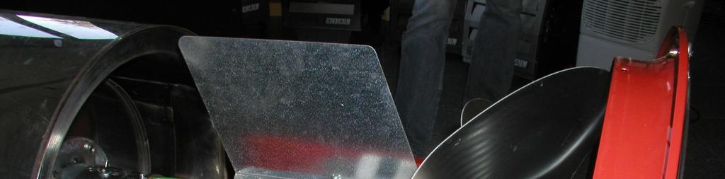
5 TOR General Assembly Front Flame Shield Burner Head Fuel Pump Combustion Chamber (open) Fuel Tank Motor Fan 5
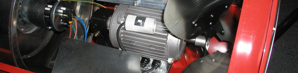
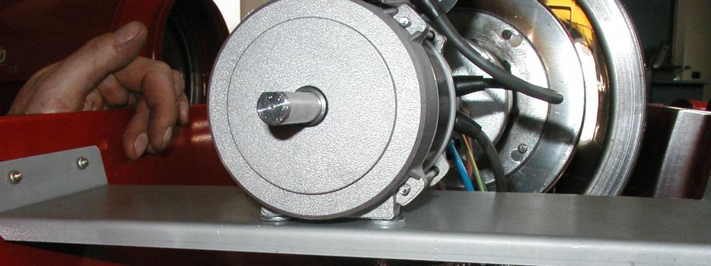
6 FAN MOTOR ASSEMBLY EU Motors 430W 2700 rpm 2 poles 16 µf MIR 37 WE - MIR 55 WE - TOR 67 WE 750W 1400 rpm 4 poles 20 µf MIR 85 WE - TOR 115 WE US Motors 430W 3300 rpm 2 poles 50 µf MIR 37 WU - MIR 55 WU - TOR 67 WU 750W 1650 rpm 4 poles 80 µf MIR 85 WU - TOR 115 WU 1100W 1650 rpm 4 poles 100 µf TOR 175 WU 6
7 FUEL CIRCUIT The fuel circuit is basically composed of : fuel tank suction and return hoses fuel filter (normal or heated) fuel pump fuel solenoid valve high pressure microhose burner head nozzle 7
 MIR 37 WE/WU - MIR 55 WE/WU -")
 MIR 85 WE/WU - TOR 115 WE 139 l")
8 Fuel Tank Available Tank Capacities 51 l (13.5 US gal) MIR 37 WE/WU - MIR 55 WE/WU - TOR 67 WE/WU 100 l (26.5 US gal) MIR 85 WE/WU - TOR 115 WE 139 l (36.7 US gal) TOR 175 WU 8
9 Fuel Filter Standard Filter Heated Filter 9
 Fuel pump filter")

10 Fuel Pump Danfoss BFPC fuel pump (front view) Fuel pump filter BFPC 21R3 MIR 37 MIR 55 TOR 67 BFPC 21R5 MIR 85 TOR 115 TOR

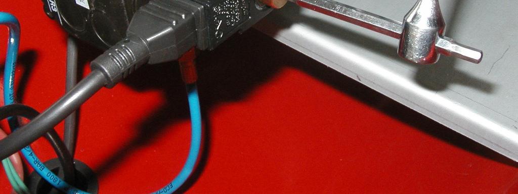

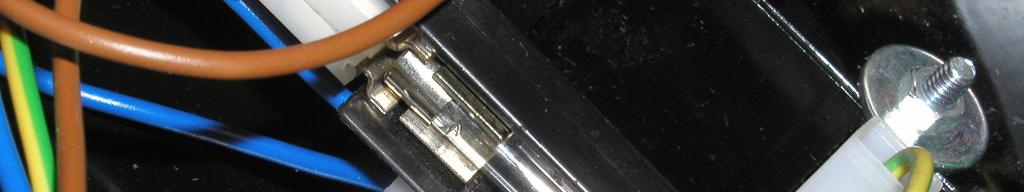
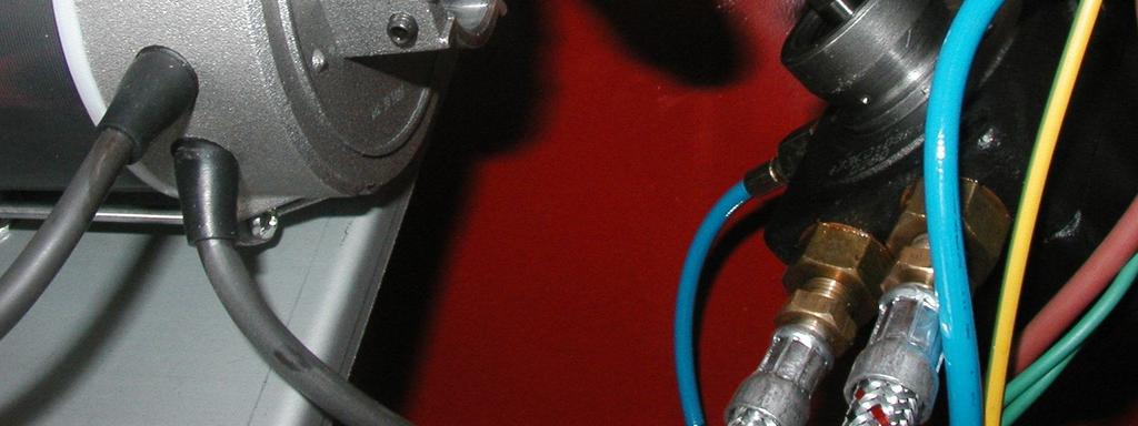
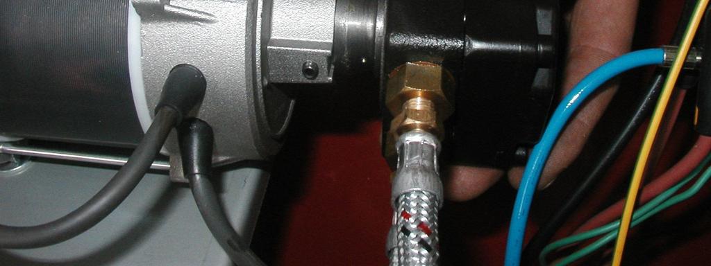
11 Fuel Cutoff Valve 11


12 BURNER ASSEMBLY Swirl disc Ignition electrodes Fuel Nozzle Air Shutter Nozzle Holder Flame Sensor 12
13 BURNER ASSEMBLY The burner assembly includes : nozzle holder air shutter swirl disc fuel nozzle 13
14 BURNER ASSEMBLY ignition electrode air shutter 14


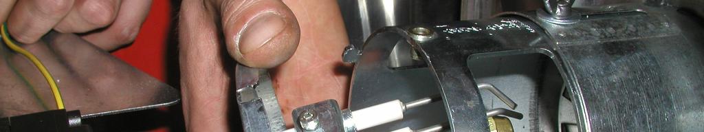
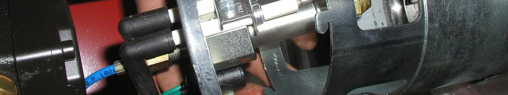
15 BURNER ASSEMBLY Removing burner head for maintenance and service 15


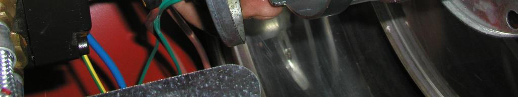
16 CHAMBER INLET Removing chamber inlet for maintenance/cleaning 16


 17")
17 COMBUSTION CHAMBER Combustion chamber (MIR) Combustion chamber inside (MIR) TOR Combustion Chamber Protection Shield (TOR) 17


18 TOR 175 WU Special Features Special swirl disc Special BCU with shortened safety time: 5 s 18


19 TOR 175 WU Special features 19
20 WIRING DIAGRAM (TOR/MIR EU) 20
21 WIRING DIAGRAM (TOR 67/MIR 37/MIR55) 21
22 WIRING DIAGRAM (TOR 115/TOR 175/MIR 85) 22
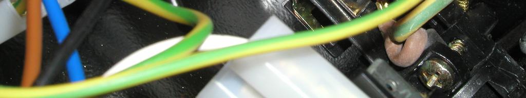
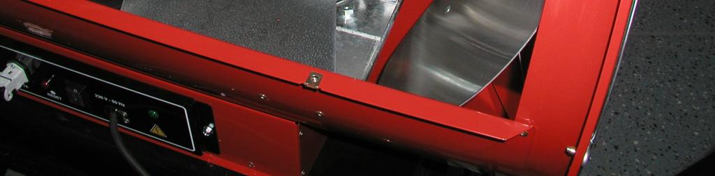
23 ELECTRICAL BOARD The electrical board consists of: Control panel Protection casing (against water/dust) Power cable with strain relief and plug ON/OFF switch Room thermostat receptacle and cap with inner jumper (to close circuit for operation without thermostat) Reset pushbutton with built-in warning lamp High voltage ignition transformer Fuse with fuseholder Electronic burner (flame) control unit (BCU) Power Lamp 23


24 Control Panel and Protecting Cover Room Thermostat Socket Power Cable ON-OFF Switch Reset Pushbutton Power Lamp Protection Cover (IPX4) 24
25 Electronic Burner Control Unit Solenoid Valve (line) Motor (line) Transformer (line) Neutral Wires Photocell Contacts Switch Contacts 25
26 SAFETY DEVICES Flame Sensor (photoresistor) Detects false flame signal or anticipated ignition Monitors flame at ignition Monitors flame failure during operation Safety Thermostat (limit control, EU models only) Prevents unit overheating Requires manual reset Line Fuse Protects unit from overcurrents 26
 Monitors")

27 SAFETY DEVICES Air Pressure Switch (US models only) Monitors fan pressure Shuts burner off in case of reduced pressure/airflow 27
28 TOR-MIR OPERATIONAL SEQUENCE 28
29 BASIC SERVICE PROCEDURES 29


30 Line Fuse Check 30


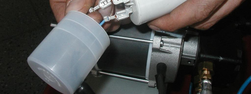
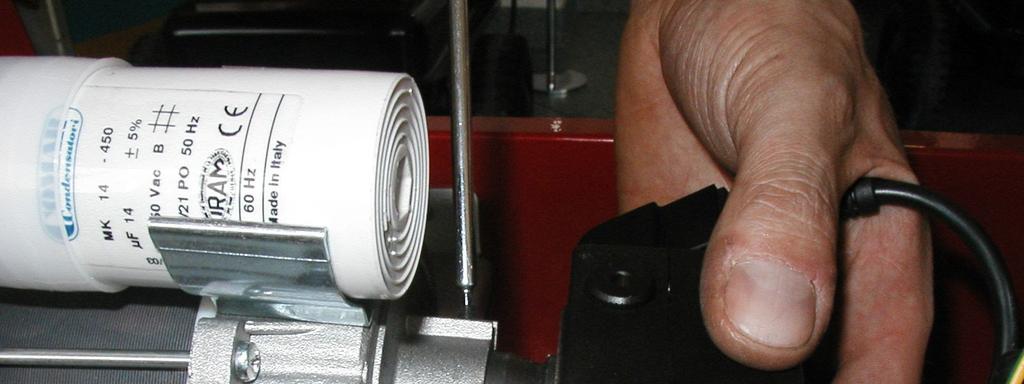
31 Fan motor/capacitor check 31

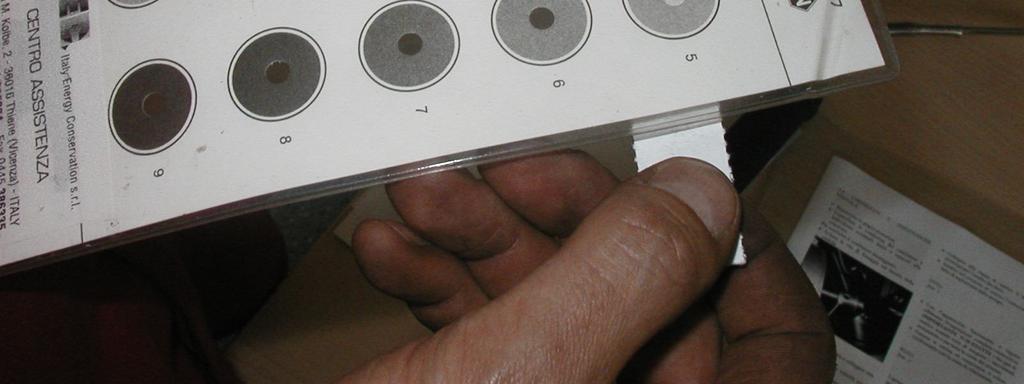


32 Smoke Index Test (Bacharach-Shell, indirect only) 1 IMPORTANT : 10 TIMES EXACTLY 32


33 Air Shutter Adjustment 33


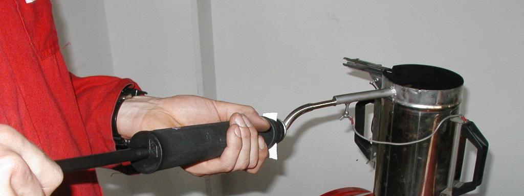
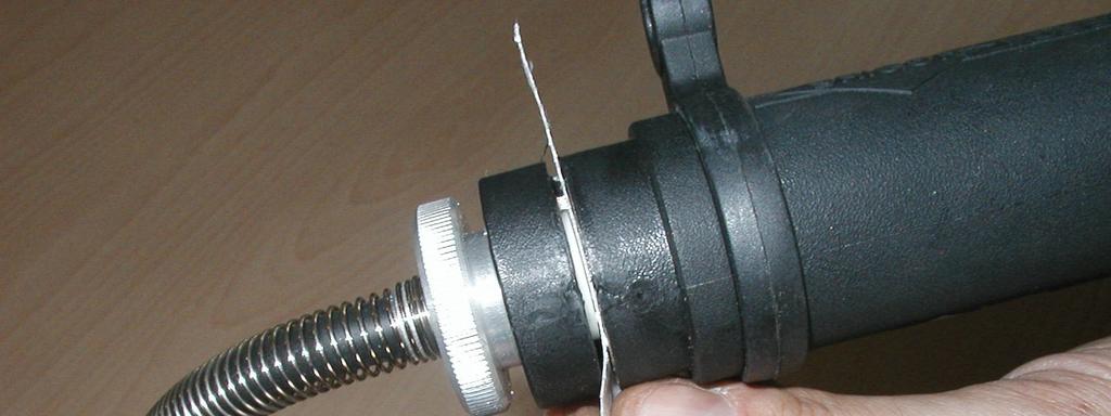
34 Fuel Filter Maintenance 34

35 Burner Nozzle Maintenance 35


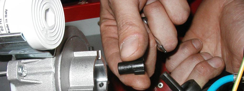
36 Burner Head Maintenance 36
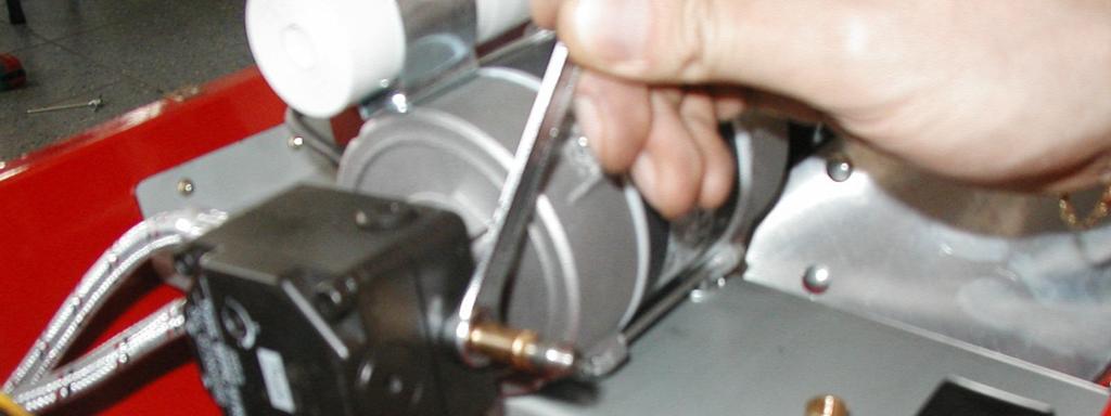
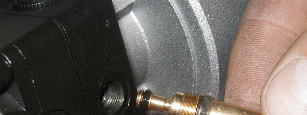
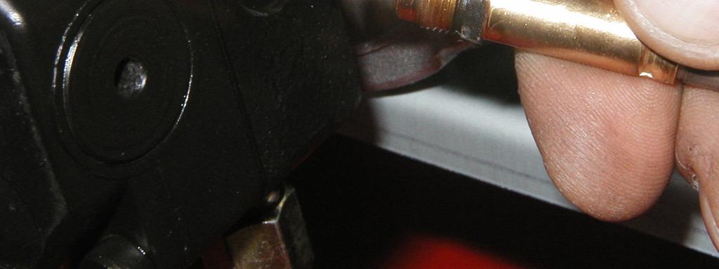
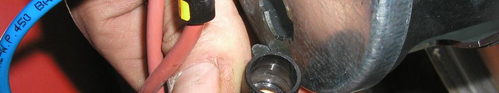
37 Fuel Pump Replacement 37


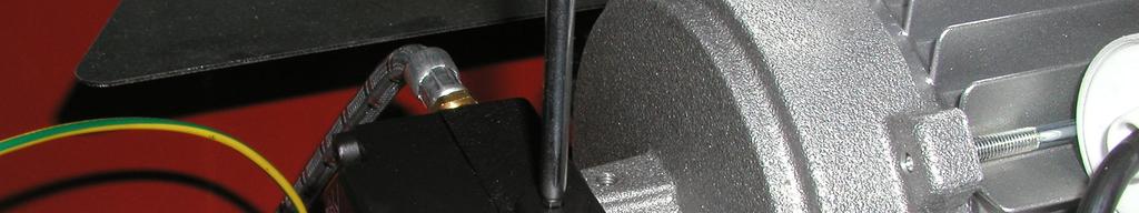

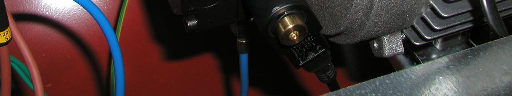
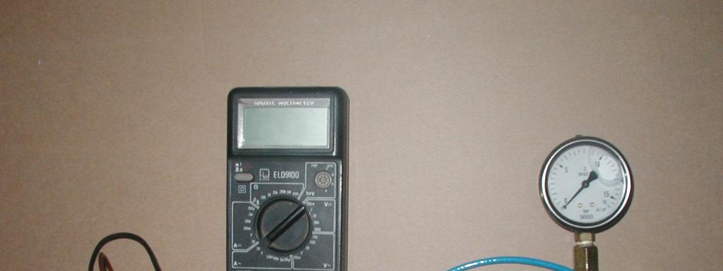
38 Fuel Pressure Adjustment Pump pressure setting for all TOR/MIR: 12 bar (175 psi) 38

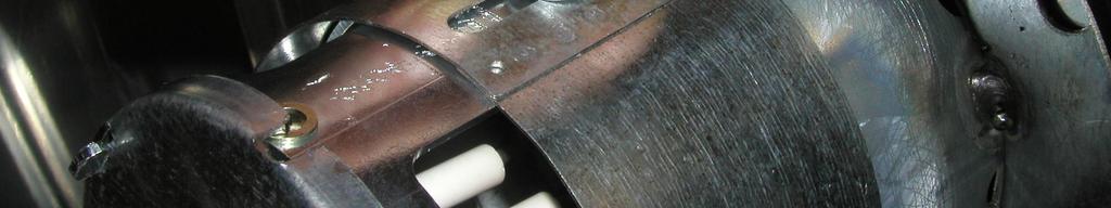
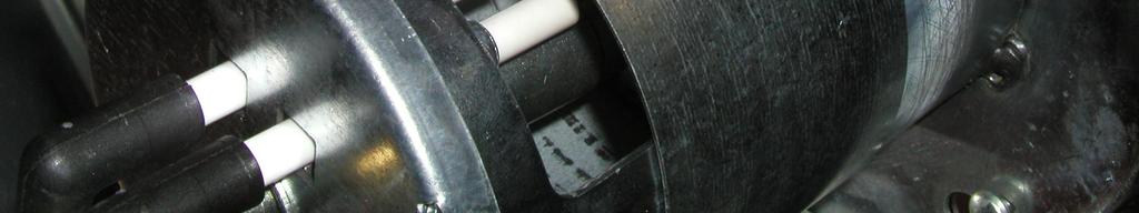
39 Ignition Electrode Service 39


40 Flame Sensor Service Typical sensor resistance values Light Dark ~ 100 ~ 100 k or more, tending to 40
41 Limit Control Reset Thermostat Settings Indirect Heaters: 170 C (338 F) Direct Heaters: 100 C (212 F) 41
42 Installation Guidelines Exhaust Pipe Design CORRECT INCORRECT 42
43 Installation Guidelines Air Ducting 43


44 Installation Guidelines Air Ducting Accessories MIR 37/55 MIR 85 max duct length: 40 ft max duct length: 60 ft 44
45 TROUBLESHOOTING SWITCH ON Check mains voltage (see data plate) Check that the green warning lamp on control panel is alight If heater is not powered: Check all electrical connections Check warning lamp Check fuse (burn-outs, damages, etc.) If fuse is burnt: Replace, use same type/rating THE HEATER STARTS no Check burner control unit See Service Manual Replace burner control unit yes 45
46 Check that lock-out warning lamp (red) is not alight Lock-out from previous operation: Wait 30 seconds and press reset button Check that overheat thermostat has not been activated Safety thermostat action from previous operation: Open inspection cover and push thermostat reset button Check that room thermostat is properly connected and adjusted Check connections Set on a temperature higher than room temperature For operation without remote thermostat: check that thermostat socket cap is correctly inserted Check electric jumper inside cap Reinsert and lock cap 46
47 Check that fuel tank is full Fill tank with proper clean fuel Check for air bubbles or leaks in fuel lines Tighten fuel line fittings Check for damages/cracks in fuel hoses THE HEATER STARTS, THE PREPURGE SEQUENCE STARTS BUT THEN THE HEATER STOPS WITHOUT IGNITION no yes Check that nozzle is clean Check that swirl disc is clean Check that flame sensor is not damaged, clean and properly fixed in its seat See Service Manual Cleaning the combustion head See Service Manual Cleaning the combustion head Clean flame sensor with a soft cloth and ethylic alcohol Replace flame sensor if damaged or burnt Check air shutter adjustment See Setting Chart Check presence of external false flame signals (sunlight, lamps, etc.) during prepurge time Check - and remove - light reflections due to sunrays, lamps etc. that could reach and disturb the flame sensor Look for flames inside chamber 47
48 Check nozzle size Check for correct nozzle size on setting chart. Replace nozzle if necessary Check air shutter adjustment See setting chart HEATER STARTS, FLAME IGNITES BUT COMBUSTION IS NOT GOOD yes Check that nozzle is clean Check that fuel filter is clean Clean or Replace nozzle See Service Manual chapter 3.8 See Service Manual chapter 3.7 no Check that pump filter is clean See Service Manual chapter
49 Check that there are no air bubbles in the fuel lines Tighten fittings Replace faulty pipes/hoses Incorrect fuel pressure Measure and adjust fuel pressure Replace pump (see Service Manual chapter 3.12) Fuel of incorrect type, dirty, polluted or containing water Empty tank and refill with clean fuel of proper type 49
50 THE BURNER SHUTS OFF DURING OPERATION AND THE FAN CONTINUES TO ROTATE (US MODELS ONLY!) yes Trip of air pressure switch Check air inlet/outlet for blockage, restrictions, etc. Check supply voltage, motor fan rpm, fan blades, fan/shaft coupling no 50
51 Excessive overheating of combustion chamber (overheat thermostat correctly activated) Wrong (too large) nozzle size Wrong (too high) fuel pressure Insufficient ventilation air due to motor fault Insufficient ventilation air due to fan failure Blockage of air inlet/outlet due to dirt or foreign objects Exhaust pipe obstruction Combustion chamber clogged by soot. (see chapter.3.10) THE HEATER SUDDENLY STOPS yes no Overheat thermostat incorrectly activated Wrong location of overheat thermostat (after incorrect service, repairs etc.) Wrong thermostat setting/type Faulty thermostat OK 51
52 MIR WE (EU) - SETTING CHART CHAMBER INLET FAN SWIRL DISC FUEL PUMP FUEL PRESSURE BURNER NOZZLE AIR LOCK OPENING OVERHEAT THERMOSTAT MIR 37 WE (EU) # 8 holes 6 mm dia. dia.=350mm 3 blades 22 out. dia.=76mm in. dia.=27mm 10 blades DANFOSS R3 12 bar DANFOSS H 3 mm lock position C (red markings) MIR 55 WE (EU) # 8 holes 6 mm dia. dia.=350mm 4 blades 18 out. dia.=76mm in. dia.=27mm 10 blades DANFOSS R3 12 bar DANFOSS H 6 mm lock position C (red markings) MIR 85 WE (EU) # 8 holes 10 mm dia. dia.=500mm 4 blades 33 out. dia.=76mm in. dia.=22mm 10 blades DANFOSS R5 12 bar DELAVAN W 20 mm lock position C (red markings) 52
53 TOR WE (EU) - SETTING CHART CHAMBER INLET FAN SWIRL DISC FUEL PUMP FUEL PRESSURE BURNER NOZZLE AIR LOCK OPENING OVERHEAT THERMOSTAT TOR 67 WE (EU) # 8 holes dia. 6 mm dia.=350mm 4 blades 18 out. dia.=76mm in. dia.=27mm 10 blades DANFOSS R3 12 bar DANFOSS H 10 mm lock position C (black markings) TOR 115 WE (EU) # 8 holes dia. 10 mm dia.=500mm 4 blades 33 out. dia.=76mm in. dia.=27mm 10 blades DANFOSS R5 12 bar DELAVAN W 28 mm lock position C (black markings) 53
54 MIR WU (USA) - SETTING CHART CHAMBER INLET FAN SWIRL DISC FUEL PUMP FUEL PRESSURE BURNER NOZZLE AIR SHUTTER SETTING OVERHEAT THERMOSTAT MIR 37 WU USA # 8 holes 6 mm dia. dia.=350mm 3 blades 18 out. dia.=76mm in. dia.=27mm 10 blades DANFOSS R3 12 bar 175 psi DANFOSS H 3 mm lock position C (red markings) MIR 55 WU USA # 8 holes 6 mm dia. dia.=350mm 3 blades 18 out. dia.=76mm in. dia.=27mm 10 blades DANFOSS R3 12 bar 175 psi DANFOSS H 7 mm lock position C (red markings) MIRAGE 85 WU USA # 8 holes 10 mm dia. dia.=500mm 4 blades 33 out. dia.=76mm in. dia.=22mm 10 blades DANFOSS R5 12 bar 175 psi DELAVAN W 14 mm lock position C (red markings) 54
55 TOR WU (USA) - SETTING CHART CHAMBER INLET FAN SWIRL DISC FUEL PUMP FUEL PRESSURE BURNER NOZZLE AIR SHUTTER SETTING OVERHEAT THERMOSTAT TOR 67 WU USA # 8 holes dia. 6 mm dia.=350mm 3 blades 18 out. dia.=76mm in. dia.=27mm 10 blades DANFOSS R3 12 bar 175 psi DANFOSS H 4 mm lock position C (black markings) TOR 115 WU USA # 8 holes dia. 10 mm dia.=500mm 4 blades 33 out. dia.=76mm in. dia.=27mm 10 blades DANFOSS R5 12 bar 175 psi DELAVAN W 13 mm lock position C (black markings) 55
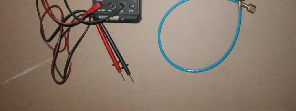
56 SERVICE & MAINTENANCE TOOLS 56
Mobile Diesel Heaters GRY-D / GRY-I Service Training Course
 Mobile Diesel Heaters GRY-D / GRY-I Service Training Course 1 Rev. No. 3 January 24, 2011 GRY-I Indirect-fired Diesel Heaters GRY-I 15 WU GRYP 50 AP GRY-I 25 WU GRYP 90 AP GRY-I 40 WU GRYP 135 AP 2 GRY-D
EC 200 EC 300 GE 360 GE 400 GE 600 L-S BM
 DIESEL SPACE HEATER - SERVICE MANUAL INDEX 1. CONTROLS AND COMPONENTS 2. FLAME CONTROL CYCLES 3. MAINTENANCE SCHEDULE 4. REPAIR PROCEDURES 1. FAN MOTOR ASSEMBLY 2. FUEL FILTER ASSEMBLY 3. FUEL PUMP ASSEMBLY
HVF110, 210, 310, 410HD
 342 N. Co. Rd. 400 East Valparaiso, IN 46383 219-464-8818 Fax 219-462-7985 www.heatwagon.com Installation and Maintenance Manual Please retain this manual for future reference. HVF110, 210, 310, 410HD
VAL6 KBE5S. Service Manual
 VAL6 KBE5S Service Manual 1 2 Specifications Type VAL6 KBE5S Heat Output 111,000BTU/h Fuel Kerosene, Diesel Tank Capacity 9 gallons Fuel Consumption 0.85gallon/h Power Source 120V, 60Hz single phase Power
PAGE 1. TES Operation & Testing Guidelines: Tes Trouble shooting
 PAGE 1 This document outlines questions to ask and components to check during TES troubleshooting. More detailed troubleshooting procedures are available in the TES Troubleshooting Guide. 1. Flow Light
Kerosene - oil burner
 Installation, use and maintenance instructions Kerosene - oil burner Two stage operation CODE MODEL TYPE 3746686 G0D 76T8 90 (0) TECHNICAL FEATURES Thermal power output 44 / 54 0 kw 3.7 / 4.5 0 kg/h Fuel
CODE MODEL TYPE G3BF 490T G5BF 492T G5BF 489T53
 Installation, use and maintenance instructions Kerosene burners One stage operation CODE MODEL TYPE 3749053 G3BF 490T53 374957 G5BF 49T57 3748953 G5BF 489T53 9036 (6) TECHNICAL FEATURES TYPE - Boiler
Service Manual. Contents. Names of components. 3. Specifications Wiring Diagam Sequence Time Chart
 Service Manual Contents 1. Names of components 2 2. Safety Devices 3 3. Specifications 4 4. Wiring Diagam 4 5. Sequence Time Chart 5 6. 7. 8. Troubleshooting 6 Standard resistance & Voltage 13 Check &
Light oil - kerosene burner
 Installation, use and maintenance instructions Light oil - kerosene burner One stage operation CODE MODEL TYPE 3747455 G0KI 474T5 90403 (4) - 0/008 TECHNICAL DATA Thermal power output 95 3 kw 8 8 kg/h
XL9 E-S Serial number N for XL9 E Edition 2005
 XL9 E-S MODEL MAIN UNIT 1 ILLUSTRATED PARTS BREAKDOWN Serial number N.25600202 for XL9 E Edition 2005 1-10 1-10 1-1 1-9 1-8 1-2 1-3 1-7 1-11 1-4 1-5 1-12 1-6 XL9 E-S MODEL MAIN UNIT 2 ILLUSTRATED PARTS
HVF110, 210, 310, 410HD
 342 N. Co. Rd. 400 East Valparaiso, IN 46383 219-464-8818 Fax 219-462-7985 www.heatwagon.com Installation and Maintenance Manual Please retain this manual for future reference. HVF110, 210, 310, 410HD
Oil - kerosene burner
 Installation, use and maintenance instructions Oil - kerosene burner One stage operation CODE MODEL TYPE 374445 G5 444T50 9038 () TECHNICAL FEATURES Thermal power output 8 0 kw.3 5 kg/h Fuel Gas oil 35s,
Trouble Shooting Guide EWA, 3-phase (D2422)
") Trouble Shooting Guide EWA, 3-phase (D2422) Trouble Shooting Guide Problem Possible Cause Possible Remedy Unit does not start Breaker tripped, no power to unit Loose wire Defective contactor or coil Close
Trouble Shooting Guide EWA, 3-phase (D2422) Trouble Shooting Guide Problem Possible Cause Possible Remedy Unit does not start Breaker tripped, no power to unit Loose wire Defective contactor or coil Close
XL9E-S Edition2005. Serial numbern forxl9e
 XL9E-S MODEL MAIN UNIT 1 Serial numbern.25600202 forxl9e ILLUSTRATED PARTS BREAKDOWN Edition2005 1-10 1-10 1-1 1-9 1-8 1-2 1-3 1-7 1-11 1-4 1-5 1-12 1-6 XL9E-S MODEL MAIN UNIT 2 Serial numbern.25600202
CODE MODEL TYPE PRESS GW 605 T80
 Installation, use and maintenance instructions Pressure jet burner CODE MODEL TYPE 3473784 PRESS GW 605 T80 291 (2) - 08/2012 Thermal power 107 / 178-350 kw - 92.000 / 153.000-301.000 kcal/h Output 9/15-30
VAL6 Infrared Heater KBE5S & KBE5L. (2-step) Maintenance Manual
 Maintenance Manual") VAL6 Infrared Heater KBE5S & KBE5L (2-step) Maintenance Manual Wiring Diagram of Burner Control KBE5S KBE5L 2-step Sequence Time Chart Operation Switch ON ignition OFF Fan Igniter Solenoid Pump 5 sec.
VAL6 Infrared Heater KBE5S & KBE5L (2-step) Maintenance Manual Wiring Diagram of Burner Control KBE5S KBE5L 2-step Sequence Time Chart Operation Switch ON ignition OFF Fan Igniter Solenoid Pump 5 sec.
HOT WASHER MODEL NO: KING 125 OPERATION & MAINTENANCE INSTRUCTIONS PART NO: LS1009
 HOT WASHER MODEL NO: KING 125 PART NO: 7320170 OPERATION & MAINTENANCE INSTRUCTIONS LS1009 INTRODUCTION Thank you for purchasing this Hot Washer. This machine is a portable, high pressure power washer,
Installation and Maintenance Manual Please retain this manual for future reference.
 342 N. Co. Rd. 400 East Valparaiso, IN 46383 219-464-8818 Fax 219-462-7985 www.heatwagon.com Installation and Maintenance Manual Please retain this manual for future reference. DG250/DG400 Ductable Construction
SERVICE MANUAL (INTERNATIONAL)
") SERVICE MANUAL (INTERNATIONAL) IMPINGER CONVEYOR OVENS MODEL 1433-000-E, 1434-000-E, 1456, 1457 WITH PUSH BUTTON CONTROLS Lincoln Foodservice Products, LLC 1111 North Hadley Road Fort Wayne, Indiana 46804
SERVICE MANUAL (INTERNATIONAL) IMPINGER CONVEYOR OVENS MODEL 1433-000-E, 1434-000-E, 1456, 1457 WITH PUSH BUTTON CONTROLS Lincoln Foodservice Products, LLC 1111 North Hadley Road Fort Wayne, Indiana 46804
AHE S - 12 VDC AHE X - 12 VDC AHE X - 12 VDC
 Shop Manual Model Numbers AHE-100-04S - 12 VDC AHE-120-04X - 12 VDC AHE-130-04X - 12 VDC TABLE OF CONTENTS Section 1 Section 2 Section 3 Section 4 General Heater Information 1.1 Component Overview 1.2
Troubleshooting Manual
 Troubleshooting Manual NOTICE: DO NOT DISCARD THIS MANUAL Models: LEGACY42-IFT PHOENIX42-IFT 1 TABLE OF CONTENTS A. Normal Operation...3 B. Wiring Diagram...4 C. Troubleshooting IntelliFire Touch...5 D.
Modulating Furnace Information. Warning on Meter Setting - Read First!
 Modulating Furnace Information Pressure Transducer Pressure DC Volts 0.00" 0.25 0.20" 0.63 0.25" 0.72 0.30" 0.82 0.35" 0.91 0.40" 1.00 0.45" 1.09 0.50" 1.19 0.55" 1.28 0.60" 1.38 0.65" 1.47 0.70" 1.56
Installation- and maintenance instruction B80-2/3
 Installation- and maintenance instruction B80-2/3 1 171 625 22 05-01 178 002 64 DESCRIPTION COMPONENTS 1. Flame cone 2. Shrouded disc 3. Nozzle 4. Nozzle assembly 5. Ignition electrodes 6. Ignition cable
E Series CE Approved Intermittent Pilot Ignition Control
 Installation Instructions Issue Date January 11, 2013 E Series CE Approved Intermittent Pilot Ignition Control Application The E Series CE Approved Intermittent Pilot Ignition Control is a safety control
DIAGNOSIS AND TESTING
 412-00-1 Climate Control System - General Information 412-00-1 DIAGNOSIS AND TESTING Climate Control System Refer to Wiring Diagrams Cell 54, Air Conditioning/Heater for schematic and connector information.
TECHNICAL SERVICE DEPARTMENT Technical Service Bulletin LowNOx Commercial Gas Electronic Spark Ignition Sequence
 The Universal TM gas LowNOx series water heaters contain an electronic spark ignition system. The heater is connected to a 120VAC power source required by the transformer. The transformer steps down the
Installation- and maintenance instruction BENTOFLEX ST 108 PL
 Installation- and maintenance instruction BENTOFLEX ST 108 PL 1 171 625 30 03-01 178 001 13 DESCRIPTION COMPONENTS 1. Reset button 2. Control box 3. Ignition transformer 4. Ignition cables 5. Nozzle assembly
SYMPTOM POSSIBLE CAUSES CORRECTIVE ACTION
 Troubleshooting SYMPTOM POSSIBLE CAUSES CORRECTIVE ACTION WILL NOT RUN RUNS BUT WON'T SPRAY LOW SPRAY AT NOZZLE UNEVEN SPRAY PATTERN WILL NOT PRODUCE HOT WATER Pump switch in OFF position Place switch
Hayward error codes and troubleshooting
 http://waterheatertimer.org/intermatic-trippers-and-parts.html#pool 50 Hayward error codes and troubleshooting Section V. TROUBLESHOOTING http://www.hayward-pool.com/prd/in-ground-pool-manuals_10201_10551_14502_-1
Installation- and maintenance instruction BENTOFLEX ST120KAV
 Installation- and maintenance instruction BENTOFLEX ST120KAV 1 171 625 61 05-01 178 001 16 DESCRIPTION COMPONENTS 1. Reset button 2. Control box 3. Ignition transformer 4. Ignition cables 5. Nozzle assembly
MODEL B360 E ILLUSTRATED PARTS BREAKDOWN UNIT 1. From Serial Number: Untill Serial Number: Edizione 2010 Rev. A. Cod
 UNIT 1 From Serial Number: 30200001 Untill Serial Number: 31200284 1 ILLUSTRATED PARTS BREAKDOWN Edizione 2010 Rev. A 2 11 10 9 7 3 12 14 30 8 6 5 4 13 15 17 16 18 19 20 28 21 22 27 29 25 24 23 26 Cod.
G600 Series Replacement Intermittent Pilot Ignition Controls
 Installation Instructions G600 Issue Date 0601 G600 Series ment Intermittent Pilot Ignition Controls Installation IMPORTANT: These instructions are intended as a guide for qualified personnel installing
MAINTENANCE CHECKLIST & SCHEDULE FOR THE IDH RANGE
 MAINTENANCE CHECKLIST & SCHEDULE FOR THE IDH RANGE INDUSTRIAL DIESEL HEATERS Details about recommended maintenance checks, components brief and how to check and replace parts as part of the maintenance
BLOWER VACUUM SWITCH FAILED OPEN
 F1 F1 AC BLOWER VACUUM SWITCH FAILED CLOSED AC BLOWER VACUUM SWITCH FAILED CLOSED UHS If the blower vacuum switch is closed before blower start-up, the control module will not start the blower. Pre-check
Installation- and maintenance instruction BENTOFLEX ST133KA/K
 Installation- and maintenance instruction BENTOFLEX ST133KA/K 178 007 17 DESCRIPTION Components 1. Reset button 2. Control box 3. Ignition transformer 4. Ignition cables 5. Nozzle assembly 6. Nozzle 7.
SECTION AIR INTAKE SYSTEM
 09-500.295/ 1 2007AL05 SECTION 09-500.295 AIR INTAKE Air for the engine is taken in through a grille located on the upper-rear, left-hand side of the vehicle. See Figure 1. Air passes through a chamber,
Heating and Gas Installations - December 2014
 This is an example of good practice maintenance specifications. It is not exhaustive and should only be used to assist with facilities management or specification of a maintenance contract. Emergency Gas
MASTER DIRECT OIL HEATERS. MODEL 35 CED 10 kw Model ILLUSTRATED PARTS BREAKDOWN. Motor and Pump Assembly
 MODEL 35 CED 10 kw Model ILLUSTRATED PARTS BREAKDOWN 3 1 2 4 5 11-5 11-1 11-2 6 7 8 11 15 11-4 23 13 41 16 17 11-3 18 1 24 20 33 34 27 3 43 25 31 37 2 30 28 26 42 35 12 32 18-1 18-2 18-18 36 18-4 18-5
RAYPAK ILLUSTRATED PARTS LIST
 COMMERCIAL MODELS: MVB 503A THRU 2003A CATALOG NO. 9300.744 Effective: 12-01-17 Replaces: 03-01-17 RAYPAK ILLUSTRATED PARTS LIST MODEL SIZES: 503A, 753A, 1003A, 1253A, 1503A, 1753A & 2003A MODEL TYPES:
SER'IICING. CORlJAIR HEATER. the
 SER'IICING the CORlJAIR HEATER COPYRIGHT 1959 CHEVROLET MOTOR DIVISION GENERAL MOTORS CORPORA lion PRIMARY IGNITION UNIT: The primary ignition unit can be serviced without removing the combustion blower
Installation- and maintenance instruction ST120 S75/21
 Installation- and maintenance instruction ST120 S75/21 1 171 615 30 05-01 178 058 15 DESCRIPTION Components 1. Reset button 2. Control box 3. Ignition transformer 4. Ignition cables 5. Nozzle assembly
Installation- and maintenance instruction B20KAV/KV
 Installation- and maintenance instruction B20KAV/KV 1 171 615 33 05-01 178 035 08 DESCRIPTION COMPONENTS 1. Air intake 2. Scale, nozzle assembly 3. Nozzle assembly adjustment 4. Test nipple 5. Ignition
RAYPAK ILLUSTRATED PARTS LIST
 COMMERCIAL/POOL MODELS: MVB 504A THRU 2004A CATALOG NO. 9300.745 Effective: 11-01-18 Replaces: 12-01-17 RAYPAK ILLUSTRATED PARTS LIST MODEL SIZES: 504A, 754A, 1104A, 1504A & 2004A MODEL TYPES: MODULATING
COMMERCIAL MODELS: XTHERM 1005A THROUGH 2005A
 COMMERCIAL MODELS: XTHERM 1005A THROUGH 2005A CATALOG NO. 9300.90 Effective: 12-13-13 Replaces: NEW RAYPAK ILLUSTRATED PARTS LIST MODEL SIZES: 1005A, 1505A & 2005A MODEL TYPES: MODULATING VERTICAL BOILER
CREATIVE EQUIPMENT CC 18 Main Road, Fishers Hill, Germiston, 1401 Tel: Fax:
 Page 1 of 6 FROM SERIAL NR 7213200000 TO 7213205371 21 4201.079 POWER CORD 1 4201.000 TANK COMPLETE 22 4290.047 LOCKNUT NYLON 2 4260.006 FUEL GAUGE 23 4290.046 STRAIN RELIEF BUSHING 3 4290.026 TANK FILTER
Installation- and maintenance instruction B20KA/K
 Installation- and maintenance instruction B20KA/K 178 091 07 DISCRIPTION Components 1. Air intake 2. Scale, nozzle assembly 3. Nozzle assembly adjustment 4. Test nipple 5. Ignition cables 6. Schrouded
Installation- and maintenance instruction B20K-2
 Installation- and maintenance instruction B20K-2 1 171 615 51 05-01 178 017 09 DESCRIPTION COMPONENTS 1. Damper motor 2. Air damper 3. Photocell 4. Scale, nozzle assembly 5. Test nipple 6. Nozzle assembly
TWO STAGE GAS BURNER GULLIVER RSD SERIES RS5D 160/ kw
 TWO STAGE GAS BURNER GULLIVER RSD SERIES 160/208 345 kw The Riello Gulliver is a new model of the series of two stage gas burners, characterized for its small dimensions in spite of its high combustion
ENGINE COOLING SYSTEM
 B ENGINE A SECTION ENGINE COOLING SYSTEM CO C D CONTENTS E PRECAUTIONS... 2 Precautions for Supplemental Restraint System (SRS) AIR BAG and SEAT BELT PRE-TEN- SIONER... 2 Precautions for Liquid Gasket...
KEY. Gas. Air. Aspiration. High Voltage. Low Voltage. Data. Light. BWB-1 Parts Interconnect. Mixing Chamber. Nebuliser. Ignitor. Pump.
 BWB-1 Parts Interconnect Mixing Chamber Burner OTA Gas Adjustment Nebuliser Ignitor Pump Ignition Module 110VAC 9V DC Inverter OTA Cable 12V DC Main Board Solenoid USB/ RS232 24V DC 15V DC -15V DC 5V DC
Single Stage Rotary Vane Vacuum Pump Installation and Operation Manual RX-10 RX-21 RX-25
 V acuum Pumps Single Stage Rotary Vane Vacuum Pump Installation and Operation Manual RX-10 RX-21 RX-25 www.republicsales.com Revised 10.14 2014 Republic Sales & Manufacturing Single Stage Rotary Vane Vacuum
Installation- and maintenance instruction B20KA/K
 Installation- and maintenance instruction B20KA/K 1 171 615 27 05-01 178 091 07 DESCRIPTION COMPONENTS 1. Air intake 2. Scale, nozzle assembly 3. Nozzle assembly adjustment 4. Test nipple 5. Ignition cables
Installation- and maintenance instruction B45A2.2
 Installation- and maintenance instruction B45A2.2 160 012 85 DESCRIPTION Components 1. Flame cone 2. Fan housing 3. Fan wheel 4. Damper motor 5. Motor 6. Pump 7. Shrouded disc 8. Nozzle 9. Ignition transformer
13. FUEL SYSTEM/CARBURETOR/
 13 FUEL SYSTEM/CARBURETOR/FUEL PUMP FUEL SYSTEM --------------------------------------------------------- 13-1 SCHEMATIC DRAWING ---------------------------------------------- 13-2 OPERATION OF CARBURETOR
NSGV PT-1000 PORTABLE WELDING STATION I, O & M MANUAL
 APPLICATION OF DUST CONTROL EQUIPMENT: CAUTION - Warning Improper operation of dust control system may contribute to conditions in the work area or facility that could result in severe personal injury
k. Components not properly adjusted. Refer to machine technical manual for proper adjustment of components.
 General Troubleshooting Charts General Troubleshooting Charts Use the charts on the following pages to help in listing all the possible causes of trouble when you begin diagnosing and testing of a machine.
TECHNICAL INFORMATION S2 Canister Vacuums
 TECHNICAL INFORMATION S2 Canister Vacuums 2012 Miele USA Table of Contents A Warning and Safety Instructions... 4 1 General Information... 4 2 Cleaning and Care... 4 2.1 Vacuums and Accessories... 4 2.2
Fig Blast tube 2.Asbestos gasket 3.Flange 4.Body gasket 5. Brake plate. 6. Oil n ozzle 7.Heater 8.Rubber block 9. Transformer 10.
 DESCRIPTION Fig. 1 1.Blast tube 2.Asbestos gasket 3.Flange 4.Body gasket 5. Brake plate 6. Oil n ozzle 7.Heater 8.Rubber block 9. Transformer 10. Controller base 11.Motor 2.Photocell 13. Controller 14.
Single Stage Rotary Vane Vacuum Pump Installation and Operation Manual RX-40 RX-63 RX-100
 V acuum Pumps Single Stage Rotary Vane Vacuum Pump Installation and Operation Manual RX-40 RX-63 RX-100 www.republicsales.com Revised 02.15 2015 Republic Sales & Manufacturing Single Stage Rotary Vane
SERVICE MANUAL (INTERNATIONAL)
") SERVICE MANUAL (INTERNATIONAL) IMPINGER CONVEYOR OVENS MODEL 1421-000-E, 1454, 1455 WITH PUSH BUTTON CONTROLS Lincoln Foodservice Products, LLC 1111 North Hadley Road Fort Wayne, Indiana 46804 United States
SERVICE MANUAL (INTERNATIONAL) IMPINGER CONVEYOR OVENS MODEL 1421-000-E, 1454, 1455 WITH PUSH BUTTON CONTROLS Lincoln Foodservice Products, LLC 1111 North Hadley Road Fort Wayne, Indiana 46804 United States
Installation- and maintenance instruction BENTOFLEX ST133K
 Installation- and maintenance instruction BENTOFLEX ST133K 171 625 37 07-01 178 004 17 TECHNICAL DATA Type designation ST133K Dimensions B 200 258 ø89 54 237 158 295 Burner tube Length of burner tube Incl.
Parts & Accessories INDEX
 342 N. Co. Rd. 400 East Valparaiso, IN 46383 888-432-8924 Fax 219-462-7985 www.heatwagon.com Parts & Accessories INDEX 1800....................2-3 1800B...................4-5 950H...................6-7
MODEL MC1500 Installation and Operation Manual Important:
 MODEL MC1500 Installation and Operation Manual Important: This manual contains specific cautionary statements relative to worker safety. Read this manual thoroughly and follow as directed. It is impossible
Parts & Accessories INDEX
 342 N. Co. Rd. 400 East Valparaiso, IN 46383 888-432-8924 Fax 219-462-7985 www.heatwagon.com Parts & Accessories INDEX 1800....................2-3 1800B...................4-5 950H...................6-7
ONE STAGE GAS BURNER GULLIVER RSF SERIES RS5F kw
 ONE STAGE GAS BURNER GULLIVER RSF SERIES 160 330 kw The Riello Gulliver, is a new model of the series of one stage gas burners, developed to respond to any request for light industrial processes like bakery
PumpAgents.com - Click here for Pricing/Ordering Fuse Size (A) Open Flow GPM (LPM)
 Open Flow GPM (LPM)") PumpAgents.com - Click here for Pricing/Ordering Models 41700 / 51700 - Series Washdown Pump WASHDOWN PUMP 0 PSI (5.5 BAR) 7.5 GPM (29 LPM) 6.0 GPM (23 LPM) FEATURES High Pressure / High capacity Pumpgard
PumpAgents.com - Click here for Pricing/Ordering Models 41700 / 51700 - Series Washdown Pump WASHDOWN PUMP 0 PSI (5.5 BAR) 7.5 GPM (29 LPM) 6.0 GPM (23 LPM) FEATURES High Pressure / High capacity Pumpgard
PARTS & SERVICE MANUAL
 PARTS & SERVICE MANUAL Impinger Low Profile Advantage Digital Series (Electric) International Models MODELS: Please note that the model numbering system changed March 2007. The chart below shows the old
Heater Troubleshooting Guides
 Heater Troubleshooting Guides Table Of Contents LRZE, 3 LRZM.. 4, 5 LXi.. 6, 7 LITE LD.. 8, 9 LITE LJ.. 10, 11 LITE LG. 1, 13 LX or LT STANDARD BURNERS 14, 15 LX or LT LOW x BURNERS. 16, 17 HiE 18, 19
SPARE PARTS MANUAL VAL HEATERS
 SPARE PARTS MANUAL VAL HEATERS 2012-2013 VAL 6 SPARES 2012-11-27 1 SPARE PARTS MANUAL VAL HEATERS CONTENTS:...2 VAL 6 1-STEP/2 STEP---main unit 3 VAL 6 KB---main unit..4 VAL 6 MIDI---main unit 5 Parts
Routine Burner Service
 Routine Burner Service WARNING Rural Energy Enterprises, Inc. does not accept liability for the improper use of this information. Installation, service, and maintenance of heating equipment should be performed
SERVICE INSTRUCTIONS,HOOVER - BAGLESS CLEANERS
 SERVICE INSTRUCTIONS,HOOVER - BAGLESS CLEANERS o41oo 149 E -1 Upper Handle Handle Cap Handle Cover Rear Di_ Cup_ HEPA Front Cover pport Latch Shaft Spring Pre-Filter Rear Filter Grille Dirt Cup _,_ Front
Portable Oil Free Silent Series Compressor Operating Instructions
 Portable Oil Free Silent Series Compressor Operating Instructions NOTICE Carefully read this instruction manual before attempting to operate this compressor. MODEL # SERIAL # 1-800-551-2406 www.eaglecompressor.com
RAYPAK ILLUSTRATED PARTS LIST
 RAYPAK ILLUSTRATED PARTS LIST The parts listed are for standard equipment for this model type. Raypak reserves the right to substitute, delete or change any part without notification. The addition of options
en Hydronic Surface Heater S 3000 REPAIR MANUAL
 0178388en 002 0209 Hydronic Surface Heater S 3000 REPAIR MANUAL 0 1 7 8 3 8 8 E N S 3000 Repair Foreword Foreword Machines covered by this manual Machine Item Number S 3000 0620182 S 3000 0620218 Machine
Troubleshooting:Passenger Car
 Troubleshooting:Passenger Car Troubleshooting If the engine or other parts has the problem, it is possible to break the exchange turbocharger again. Please confirm the notes below and inspect each part
G72x Series Direct Spark Ignition Controls
 Installation Sheets Manual 121 Gas Combustion Combination Controls and Systems Section G Technical Bulletin G72x Issue Date 1299 G72x Series Direct Spark Ignition Controls Figure 1: G72x Direct Spark Ignition
COMMERCIAL and POOL MODELS: 302C THROUGH 902C
 COMMERCIAL and POOL MODELS: 302C THROUGH 902C CATALOG NO. 9300.753 Effective: 12-01-17 Replaces: 12-01-16 RAYPAK REPLACEMENT PARTS MODEL SIZES: 302C, 402C, 502C, 652C, 752C & 902C MODEL TYPES: HI DELTA
LOW NOx TWO STAGE GAS BURNERS GULLIVER BSD SERIES BS1D 16/19 52 kw BS2D 35/40 91 kw BS3D 65/ kw BS4D 110/ kw
 LOW NOx TWO STAGE GAS BURNERS GULLIVER BSD SERIES 1/19 5 kw 35/4 91 kw 5/75 19 kw 11/14 4 kw The Riello Gulliver BSD series of two stage gas burners, is a complete range of Low NOx emission products, developed
PRESS G SERIES. Two Stage Light Oil Burners FIRING RATES
 The PRESS G series of burners covers a firing range from 107 to 1660 kw and they have been designed for use in civil installations of average dimensions, like building areas and large apartment groups
PARTS LIST FOR SH-100LP, SH-155LP AND SH-375LP
 PARTS LIST FOR SH-100LP, SH-155LP AND SH-375LP Space Heaters This Parts Listing has been compiled for your benefit. You can be assured your space heater was constructed and designed with quality and performance
Updated technical data can be found in this document, supplemented by the Riello BX Burner Manual regarding commissioning checks and adjustments.
 Riello BX Low NOx Manual Addendum Introduction To ensure compliance with commission Regulation (EU) No 813/2013, implementing Directive 2009/125/EC of the European Parliament and of the Council with regard
Section 3 Technical Information
 Section 3 Technical Information In this Module: Engine identification Modes of operation Battery charging and heat manage operation Service and repair procedures Maintenance requirements Engine Identification
M-3025CB-AV Fuel Pump
 SAVE THESE INSTRUCTIONS M-3025CB-AV Fuel Pump Owner s Manual TABLE OF CONTENTS General Information... 2 Safety Instructions... 2 Installation... 3 Operation... 4 Maintenance... 4 Repair... 5 Troubleshooting...
Maintenance of Pleasureboat Diesel Engine GM Series
 Maintenance of Pleasureboat Diesel Engine GM Series.Safety Precaution for Inspection )Battery Fluid Battery fluid is diluted sulfuric acid. It can blind you if it gets in your eyes, or burn your skin.
SERVICE MANUAL. K Series Gas Kettles 2/3 Jacketed Stationary and Tilting - NOTICE - K40GL Shown
 SERVICE MANUAL K Series Gas Kettles 2/3 Jacketed Stationary and Tilting K20GL K40GL K60GL K20GLT K40GLT K60GLT ML-136090 ML-136091 ML-136092 ML-136094 ML-136095 ML-136096 K40GL Shown - NOTICE - This Manual
by TELEFLEX SERVICE MANUAL M50/M80/M105
 by TELEFLEX SERVICE MANUAL M50/M80/M105 CONTENTS A. SAFETY...A-1 SAFETY CONSIDERATIONS...A-2 B. INTRODUCTION...B-1 1.0 TECHNICAL SPECIFICATIONS...1-1 1.1 PHYSICAL...1-2 1.2 ELECTRICAL...1-3 2.0 PRINCIPLES
RAYPAK ILLUSTRATED PARTS LIST
 RAYPAK ILLUSTRATED PARTS LIST The parts listed are for standard equipment for this model type. Raypak reserves the right to substitute, delete or change any part without notification. The addition of options
ONE STAGE GAS BURNERS RDBS SERIES
 ONE STAGE GAS BURNERS RDBS SERIES 16 47 kw RDBS.1 16 47 kw The Riello RDBS is a new series of one stage gas burners with integrated gas train, characterised by its small dimensions in spite of its high
2.0 Burner Operating Parameters and Requirements
 ECLIPSE INFORMATION GUIDE Silicon Carbide Radiant Auto-Recupes Info 322 2/99 WARNING Handle silicon carbide tubes carefully. Do not drop them or hammer on them. Although they feature excellent mechanical
LDG6000SA DIESEL GENERATOR OWNERS MANUAL
 LDG6000SA DIESEL GENERATOR OWNERS MANUAL BEFORE OPERATING THIS EQUIPMENT PLEASE READ THESE INSTRUCTIONS CAREFULLY Preface Thank-you for purchasing this generator. This operation manual contains information
Training Bulletin New Model Introduction
 GE Monogram GE Consumer Service Training Training Bulletin New Model Introduction October 2001/ TB-14-01 ZV950SDSS Wall-Mount Euro-Style High Performance Vent Hood Purpose To introduce the new wall-mount
Troubleshooting the Transmission Hydraulic System
 Testing and Adjusting IT28F INTEGRATED TOOLCARRIER POWER TRAIN Testing And Adjusting Introduction Reference: For Specifications with illustrations, refer to SENR5974, IT28F Integrated Toolcarrier Power
TFL Gas Log Lighter (TFLGLL)
") TFL Gas Log Lighter (TFLGLL) For Jetmaster Metal Fireboxes and Logpans CONTENTS Description Page No. Important information 2 Operation and Design 3 Controller Solenoid Cavity 4 Contents of a Kit 5 To install
TFL Gas Log Lighter (TFLGLL) For Jetmaster Metal Fireboxes and Logpans CONTENTS Description Page No. Important information 2 Operation and Design 3 Controller Solenoid Cavity 4 Contents of a Kit 5 To install
BIGLA30-T/BIELA14-T Event Codes Quick Reference EXPLANATION CORRECTIVE ACTION PARTS TO CARRY ON SERVICE CALL
 E13 TEMPERATURE PROBE FAILURE E16 HIGH LIMIT 1 EXCEEDED A. TEMP Probe reading out of range. B. Bad Connection. C. Problem with the temperatur e measuring circuitry including the probe. High limit temperature
INSTALLATION OPERATION/ MAINTENANCE INSTRUCTIONS AND PARTS LIST
 BT400-NEX-D5 INSTALLATION OPERATION/ MAINTENANCE INSTRUCTIONS AND PARTS LIST Report No. 459-D-01-2 Table of Contents SECTION 1 INTRODUCTION PAGE 1.1 General 4 1.2 Scope 4 1.4 Safety Precautions 4 SECTION
RS SERIES. Two Stage Progressive Gas Burners FIRING RATES
 The RS burners series covers a firing range from 44 to 2290 kw, and it has been designed for use in low or medium temperature hot water boilers, hot air or steam boilers, diathermic oil boilers. Operation
RS/M SERIES. Modulating Gas Burners FIRING RATES
 The RS/M burners series covers a firing range from 45 to 2650 kw, and it has been designed for use in low or medium temperature hot water boilers, hot air or steam boilers, diathermic oil boilers. Operation
TC Series Cooling Systems
 TC Series Cooling Systems Table of Contents Table of Contents...1 List of Figures...1 Safety...2 Introduction...2 General Specifications...2 Types of Coolant...2 Routine Maintenance...2 Surge Tank Coolant
PRECISION UK Ltd DUPLEX AGSS PLANT
 DUPLEX AGSS PLANT Contents Page Section Page Product Description General 3 AGSS Plant 3 AGSS Remote Switch 3 Operation General 4 Safety General 5 Installation General 5 Mechanical 5 Electrical 7 Wiring
Medium and high pressure pumps
 Screw pumps Medium and high pressure pumps Installation and Start-up Instruction This instruction is valid for all standard high pressure pumps: E4, D4 and D6 Contents Page Pump identification 2 Installation