Model 990DS INSTALLATIONS AND OPERATING INSTRUCTIONS
|
|
|
- Darcy Simpson
- 5 years ago
- Views:
Transcription


1 Model 990DS Advanced Marine Technologies, Inc. 212 Yacht Club Drive Saint Augustine FL FAX INSTALLATIONS AND OPERATING INSTRUCTIONS
2 2 1.0 DESCRIPTION The Model 990DS was designed specifically for larger diesel vessels with multiple engines. Particularly, the 9990DS was designed to service a vessel s two main diesel engines, each transmission or gear and one or two generators. However, the system is capable of servicing any combination six engines. The oil flow from each main engine is controlled by a separate manifold which designates the flow from the engine, its transmission and a designated generator(s). 2.0 CONSTRUCTION The 990DS is constructed with the highest quality materials selected for both wear and resistance and service life. The 990DS utilizes a heavy-duty reversible bronze body motor and rotary gear pump which has self-lubricating carbon bearings and drip-proof lip seals. Powered by a single phase, 1/3 HP 115V/60(Hz) or 230v/60(Hz) corrosion resistant motor which is overload protected, the pump is driven directly from the motor shaft by means of a flexible coupling. The motor is controlled by a three pole, double throw switch with FILL-OFF-DRAIN positions. Housed in a heavy duty, 16 gauge steel, Polane coated enclosure, the 990DS rigid construction will withstand the harshest of marine environments. 3.0 SPECIFICATIONS Phase HP Voltage Length Width Height Weight GPM 1 1/3 115V lb. 4* 1 1/3 230V lb. 4* *Flow rates are approximate and may vary due to the temperature and/or viscosity of the oil. 4.0 LOCATION AND INSTALLATION This is a permanent system for mounting on a horizontal surface in the engine room. The system should be located in a readily accessible location to allow easy operation and service. The Model 990DS has excellent priming characteristics and is capable of lifting liquids on the suction side as high as 15 feet. However, as a general rule, the suction lift should be kept as limited as possible by placing the system as central as central to all engine sources as possible. Installing the unit requires general knowledge of engine service and electrical wiring skills. If you are not familiar with these techniques, it is recommended an experienced marine mechanic be engaged to install the X-Change-R. The Model 9990DS is delivered with the enclosure unattached to allow access to the four mounting holes. Secure the system to a flat surface through the mounting holes which accommodate ¼ X 20 mechanical screws. 5.0 ELECTRICAL WIRING REQUIREMENTS
3 3 The Model 990DS is designed for use with an 115V/60(Hz) or 230v/60(Hz) power source. The system is supplied with a 6 three conductor cord which allows for easy plug-in convenience to an engine room outlet. However, if preferred, the cord can be cut and hard wired to a panel breaker. When wiring the system, choose UL approved marine-grade wire and connectors. 6.0 INSTALLATION OF THE HOSES Because oil is a viscous fluid (particularly when cool) every attempt should be made to keep the length of the hose runs at a minimum. When changing engine oil or transmission oil, a small amount of waste oil will return to the system along with the fresh oil. This is acceptable for hose runs of 15 feet or less. Hose runs of 20 feet or more should be avoided, especially when connected to transmissions or small engines. Care should also be taken to avoid sharp bends in the hose and direct exposure to hot surface. When installing the hoses, design the layout symmetrically. It is easier to determine the location of the lines and presents a neat appearance. 6.1 Connecting Engine Oil Pan Hoses 1. Drain oil from each engine 2. If the engines are not equipped with a factory installed oil pan drain hose, replace each oil pan drain plug with a drain hose assembly supplied by the engine manufacturer, or install a compatible fitting that will accommodate a ½ ID oil drain hose, an adapter may be required. 3. Connect properly measured lengths of approved ½ ID hose from each engine s oil pan drain to the appropriate manifold on the X-Change-R. 4. After completing the hose installation, carefully inspect the hose to insure 6.2 Connecting Transmission Hoses 1. Drain oil from each engine 2. If the transmissions are not equipped with a factory installed drain hose, replace each oil pan drain plug with a drain hose assembly supplied by the engine manufacturer, or install a compatible fitting that will accommodate a ½ ID oil drain hose, An adapter may be required. 3. Connect properly measured lengths of approved ½ ID hose from each transmission s oil pan drain to the appropriate manifold on the X-Change- R. 4. After completing the hose installation, carefully inspect the hose to insure 6.3 Connecting Generator Hose 1. Drain oil from each generator(s).
4 4 2. If the generator(s) is not equipped with a factory installed drain hose, replace the oil pan drain plug with a drain hose assembly supplied by the engine manufacturer, or install a compatible fitting that will accommodate a ½ ID oil drain hose, an adapter may be required. 3. Connect properly measured lengths of approved ½ ID hose from each engine s oil pan drain to the appropriate manifold on the X-Change-R. 4. After completing the hose installation, carefully inspect the hose to insure 6.4 Connecting Input/Output Valves 950GV 1. Connect the Input/Output Valves to either New/Used Oil Reservoirs or Cockpit (external connection) and Engine Room access. 2. If the Reservoirs are not equipped with a factory installed drain hose, replace the oil pan drain plug with a drain hose assembly supplied by the manufacturer, or install a compatible fitting that will accommodate a ½ ID oil drain hose, an adapter may be required. 3. Cockpit (external connection) is best connected to a quick disconnect and used for main oil change. Engine Room access is best used to top off. 4. Connect properly measured lengths of approved ½ ID hose from each connection to the appropriate manifold on the X-Change-R. 5. After completing the hose installation, carefully inspect the hose to insure 7.0 DRAINING USED OIL FROM THE ENGINES / TRANSMISSIONS / GENERATOR(S) To insure the oil maintains proper viscosity during the removal process, it is recommended the operator run the engines long enough to permit the engine block to become warm at least 140. Shut the engines down and allow ample time for the circulated oil to return to the oil pan. 7.1 Draining the Engine, Transmission or Generator 1. Warm engine to at least 140 F, then turn engine off. 2. Insert the PVC wand of the Drain/Fill hose into a container suitable for waste oil collection. (Remember, it is a legal requirement to dispose of waste oil in a responsible manner. 3. Loosen the oil filler cap on the engine or remove the dip stick to allow air to enter the crankcase. 4. Release the safe lock devise on the toggle switch. Do not turn. 5. Select the individual engine, transmission or generator on the top of the system using the BLACK HANDLE. Select the output port on the side of the system using the SILVER HANDLE (SPECIAL NOTE: Open only one valve at a time with other engine valves closed tight to prevent accidental draining or other engines.)
5 5 6. Flip the motor control switch to the DRAIN position. The pump will start immediately. You should hear a noticeable change in the sound (speed) of the pump motor when the used oil enters the pump. 7. Continue to operate the pump until there is a noticeable change in the sound (speed) of the pump motor, which is an indication air is being drawn into the crankcase oil hose and that the specified crankcase is now empty. Oil is drained at the rate of about a gallon each 15 seconds (4 gallons a minute). 8. Return the pump motor control switch to the OFF position when the crankcase is empty and shut the individual valve to OFF with BLACK HANDLE. 9. When you have completed the service, be sure to cover the safe lock handle over the toggle switch. 8.0 FILLING THE ENGINES Before attempting to fill an engine, make certain the engine has been completely drained or is in need of a measured amount of additional oil. DO NOT OVER FILL! Next, determine the type and the amount of oil recommended by the manufacturer for each engine. Remember, FOUR QUARTS = ONE GALLON. There are two commonly used methods to determine when the proper amount of oil has been delivered to the engine. Pre-measured Method this method requires the operator to set aside a known quantity of oil prior to filling. For example, if the engine requires 22 quarts of oil, the operator may want to pump from a 5-gallon container, adding 2 additional, quarts as the container empties. Timed Method the timed method is used when pumping from a container of unknown capacity or a reservoir. The flow of the oil through the system varies primarily with the viscosity and temperature of the oil. Under normal conditions (75-85 ), the system pumps approximately 4 gallons per 60 seconds. Filling time is a function of several factors, including oil temperature and weight. 8.1 Filling the Engine 1. Insert the PVC wand of the Drain/Fill hose into a container suitable for waste oil collection. (Remember, it is a legal requirement to dispose of waste oil in a responsible manner.) 2. Loosen the oil filler cap on the engine or remove the dip stick to allow air to vacate the crankcase. 3. Release safe lock devise on the toggle switch. Do not turn. 4. Select the individual engine, transmission or generator on the top of the system using the BLACK HANDLE. Select the output port on the side of the system using the SILVER HANDLE (SPECIAL NOTE: Open only one valve at a time with other engine valves closed tight to prevent accidental draining or other engines.)
6 6 5. Flip the motor control switch to the Fill position. The pump will start immediately. You should hear a noticeable change in the sound (speed) of the pump motor when the used oil enters the pump. 6. Continue to operate the pump until a measured amount of oil has been pumped into the engine s crankcase. Fresh oil is pumped at the rate of approximately 4* gallons per minute. If you do over fill an engine, you may simply flip the motor control switch to the DRAIN position for a few seconds to remove the overage. 7. Once filled, return the pump motor control switch to the OFF position when the crankcase is empty and shut the individual valve to OFF with BLACK HANDLE. When you have completed the service, be sure to cover the safe lock handle over the toggle switch. 9.0 TROUBLESHOOTING SYMPTOM POSSIBLE CAUSE(S) CORRECTIVE ACTION No Liquid Delivery 1) Closed valves 1) Open valves 2) Plugged suction 2) Eliminate restriction 3) Air leak at suction 3) Locate and repair leak 4) Suction lift too high 4) Do not exceed vapor pressure of liquid 5) Motor wired incorrectly 5) Check wiring instructions Low Liquid Delivery 1) Pump shaft speed incorrect 1) Check driver speed 2) Discharge pressure too high 2) Reduce downstream pressure 3) Air leak at suction 3) Locate and repair leak 4) Worn or damaged pump 4) Inspect and repair as required 5) Low viscosity 5) Verify original application conditions Gradually Losses Prime 1) Suction lift too high 1) Improve suction pressure 2) Air or gas in fluid 2) Eliminate air or gas from fluid 3) Air leak at suction 3) Locate and repair leak 4) Worn or damaged pump 4) Inspect and repair as required Noisy 1) Cavitating 1) Improve system suction pressure 2) Solid particles in fluid 2) Install suction strainer 3) Air or gas in Fluid 3) Eliminate air or gas in fluid 4) Worn or damaged pump 4) Inspect and repair as required Motor Runs Hot or Overloads 1) Discharge pressure too high 1) Reduce downstream pressure 2) Shaft speed too fast 2) Reduce speed 3) Fluid viscosity higher than expected 3) Change to larger horsepower 4) Incorrectly wired motor 4) Check wiring instructions 5) Binding internal pump parts 5) Inspect and correct condition 6) Motors normally feel hot 6) Verify if actual amperage draw is within range Seal Leaks 1) Dry running 1) Open valves, prime pump 2) Solids in fluids 2) Add suction strainer 3) Seal material incompatible with fluid 3) Verify original application conditions

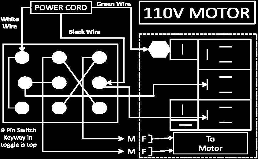
7 WIRING DIAGRAM
Model 990 & 990V INSTALLATIONS AND OPERATING INSTRUCTIONS
 Model 990 & 990V Advanced Marine Technologies, Inc. 212 Yacht Club Drive Saint Augustine FL 32084 866-922-4804 904-829-1800 FAX 904-829-2800 pumps@x-change-r.com www.x-change-r.com INSTALLATIONS AND OPERATING
LIQUIDYNAMICS Light Viscosity Bulk Transfer Cart
 This manual contains important warnings and information. READ AND KEEP FOR REFERENCE. LIQUIDYNAMICS Light Viscosity Bulk Transfer Cart Instruction & Parts Manual This Manual Covers P/N 33271 P/N 33271
Installation, Operation, and Maintenance Manual Outdoor Glycol Feed System JWOP /055/100
 Installation, Operation, and Maintenance Manual Outdoor Glycol Feed System JWOP-53-030/055/100 Rev. 1 3/21/11 K.G. Type - John Wood #JWOP-53-030/055/100, Outdoor Glycol Feed System Capacity 30/55/100 Gallons
END SUCTION CENTRIFUGAL PUMPS
 OWNERS GUIDE TO INSTALLATION AND OPERATION END SUCTION CENTRIFUGAL PUMPS FW000 0 Supersedes 009 READ THESE INSTRUCTIONS CAREFULLY Read these installation instructions in detail before installing your pump.
IMPORTANT OPERATING CONDITIONS. Failure to comply with any of these conditions invalidates the warranty. STANDARD CONFIGURATIONS
 X-SERIES TRIPLEX CERAMIC PLUNGER PUMPS OPERATING MANUAL MODELS X8 X10 X20 IMPORTANT OPERATING CONDITIONS Failure to comply with any of these conditions invalidates the warranty. Lubrication - Prior to
END SUCTION CENTRIFUGAL PUMPS
 OWNERS GUIDE TO INSTALLATION AND OPERATION FW000 009 Supersedes 07 END SUCTION CENTRIFUGAL PUMPS READ THESE INSTRUCTIONS CAREFULLY Read these installation instructions in detail before installing your
07 Oil Change & Diesel Transfer Pumps
 064 07 Oil Change & Diesel Transfer Pumps OIL CHAngE PuMPS Porta-Quick The Porta-Quick Portable Oil Changer makes quick, clean and easy oil changes onboard any boat, because it uses the vessel s own power
PRODUCT: 1500 SERIES MOBILE EXPLOSION PROOF PAGE 1 REV "BLADE MASTER" AC-EP-SINGLE PHASE-1.5 HP OPERATING AND MAINTENANCE INSTRUCTIONS
 PRODUCT: 1500 SERIES MOBILE EXPLOSION PROOF PAGE 1 REV.020112 "BLADE MASTER" AC-EP-SINGLE PHASE-1.5 HP OPERATING AND MAINTENANCE INSTRUCTIONS The "Blade Master is a high-volume, low-energy, (U.L. /C.S.A.,
NECO Pumping Systems
 INSTALLATION OPERATION & MAINTENANCE INSTRUCTIONS For Your NECO Pumping Systems Fuel Oil Transfer System THIS COMPLETELY ASSEMBLED, TESTED, PACKAGED SYSTEM IS OF THE HIGHEST QUALITY AND DESIGN. TO OBTAIN
Model &
 PumpAgents.com - Click here for Pricing/Ordering Model 31765-0092 & 31765-0094 Dual Sensor Max VSD WATER PRESSURE SYSTEM AUTOMATIC TWO STAGE WATER SYSTEM WITH PUMPGARD STRAINERS IDEAL FOR PLEASURE AND
07 Oil Change & Diesel Transfer Pumps
 64 07 Oil Change & Diesel Transfer Pumps OIL CHANGE PUMPS Porta-Quick The Porta-Quick Portable Oil Changer makes quick, clean and easy oil changes onboard any boat because it uses the vessel s own power
Centrifugal Pumps (Part Nos. PS2SS PS73SS) PS2SS
 PS2SS") Centrifugal Pumps (Part Nos. PS2SS PS73SS) PS2SS Part No. Serial Number Date Purchased Table of Contents Page Safety Messages...2 Pump Curves...2 Pump End Assembly...3 Disassembly...3 Installation...4
Centrifugal Pumps (Part Nos. PS2SS PS73SS) PS2SS Part No. Serial Number Date Purchased Table of Contents Page Safety Messages...2 Pump Curves...2 Pump End Assembly...3 Disassembly...3 Installation...4
Model and Series 115 VAC INDUSTRIAL DIAPHRAGM PUMPS. PumpAgents.com - buy pumps and parts online INDUSTRIAL DIAPHRAGM PUMPS
 Model 31801 and 31800 Series 115 VAC INDUSTRIAL DIAPHRAGM PUMPS INDUSTRIAL DIAPHRAGM PUMPS FEATURES Run Dry Ability Self-Priming Thermal Overload Protected Motor Easy Installation Low Amp Draw Compact
Hydraulic Pump Troubleshooting P & BDP Series Models
 Hydraulic Pump Troubleshooting P & BDP Series Models Hydraulic Pump damage can cause traction circuit failures and problematic hydraulic system contamination. Performance problems such as weak traction
100 Gallon Skid Sprayer
 100 Gallon Skid Sprayer Model #: KS100P17 User Manual Read this manual for complete instructions Model #: KS100P17 Table of Contents Warranty... 3 General Safety Information... 3 Hazardous Substance Alert...
Operating Manual for Rotary Gear Pumps CMI, S.A. (Mendaro, Guipuzkoa, Spain)
") Operating Manual for Rotary Gear Pumps CMI, S.A. (Mendaro, Guipuzkoa, Spain) Pre-Installation 1. Choose a location that is easily accessible for pump servicing. Ensure adequate electrical service is available.
Operating Manual for Rotary Gear Pumps CMI, S.A. (Mendaro, Guipuzkoa, Spain) Pre-Installation 1. Choose a location that is easily accessible for pump servicing. Ensure adequate electrical service is available.
Models
 Models 15300 15301 15500 15501 SAFETY PRECAUTIONS WARNING! To prevent personal injury, Wear goggles when working with refrigerants. Contact with refrigerants may cause injury. Incorrect use or connections
Pump Operating and Maintenance Manual - Models
 Pump Operating and Maintenance Manual - Models 78-00111 - 78-0057 Thank you for purchasing the SDI Diaphragm Pump manufactured by Comet Pump. Comet produces quality products which are safe, efficient and
OWNER S MANUAL EVOLUTION 3500, 4500, 5500, & 8500 SERIES PUMPS
 OWNER S MANUAL EVOLUTION 3500, 4500, 5500, & 8500 SERIES PUMPS IMPORTANT SAFETY INSTRUCTIONS When installing and using this electrical equipment, basic safety precautions should always be followed, including
Operating and Installation Instructions
 Model Number 40401-c (-sp) Electronic Fuel Pump Operating and Installation Instructions This Product is Patent Pending. Application available upon request CAUTION! This product is to be installed only
HIGH VISCOSITY FILTER SYSTEMS
 HIGH VISCOSITY FILTER SYSTEMS High Viscosity Filter Cart P/N 36970 High Viscosity Hand Held P/N 36971 Owner's Manual Table of Contents Customer Satisfaction...2 Introduction...3 Typical Applications...3
Operation and Maintenance. S100 Series Centrifugal Fire Pumps. Table of Contents. Visit us at F /22/02 6/21/18
 S100 Series Centrifugal Fire Pumps Operation and Maintenance Form No. F-1031 Section 2117 Issue Date 02/22/02 Rev. Date 6/21/18 Table of Contents Safety Information-----------------------------------------------
Installation & Operating Manual
 Installation & Operating Manual 25IPCC-M 7/08 Edition PC Series C E N T R I F U G A L Congratulations On Your Choice In Purchasing This Webtrol Pump Its Quality is unsurpassed in material and workmanship
Operating Instructions & Parts Manual
 Operating Instructions & Parts Manual Grainger Model No. 36NE14 Bucher Hydraulics Model No. M-4509-0217 Please read the instructions carefully and always operate this equipment in a safe manner. Unit Description:
Portable Filter Carts Models 5MF and 10MF
 s Models 5MF and 10MF 161 Applications for Parker Filter Carts Filtering new fluid before putting into service Transferring fluid from drums or storage tanks to system reservoirs Conditioning fluid that
Table 6-1. Problems and solutions with pump operations. No Fluid Delivery
 Table 6-1. and solutions with pump operations No Fluid Delivery Fluid level in the reservoir is low. Oil intake pipe or inlet filter is plugged. Air leak in the inlet line prevents priming or causes noise
Regenerative Turbine Pumps
 Bulletin E4 November 009 E4 T4 Series Regenerative Turbine Pumps Capacities to GPM Heads to 600 Feet Temperatures to 00 F MTH PUMPS MTH E4 T4 Series Close-coupled and pedestal mounted regenerative turbine
Installation, Operating, Maintenance and Safety Instructions for CW332 Pressurised water system for boats 24 volt d.c.
 24V DC-CW332 DOC531/11 Installation, Operating, Maintenance and Safety Instructions for CW332 Pressurised water system for boats 24 volt d.c. To obtain the best performance from your Pressurised water
Self-Priming Close-Coupled Centrifugal Pumps In 316 Stainless Steel, Bronze and Cast Iron
 Please read and save this Repair Parts Manual. Read this manual and the General Operating Instructions carefully before attempting to assemble, install, operate or maintain the product described. Protect
Operating instructions Form no safety definitions
 Operating instructions Form no. 1000437 safety definitions safety symbols are used to identify any action or lack of action that can cause personal injury. Your reading and understanding of these safety
SHURflo Pedestal-Mount Centrifugal Pumps
 316 Stainless Steel, Bronze and Cast Iron Models Please read and save this Repair Parts Manual. Read this manual and the General Operating Instructions carefully before attempting to assemble, install,
Voltmaster Centrifugal Trash Pumps
 Voltmaster Centrifugal Trash Pumps Model TSP2, TSP3 and TSP4 Owner s Manual February 2011 Table of Contents 1 Introduction............................ 1 1.1 Read before using..................... 1 1.2
Tank Sealcoating Spray Systems
 Tank Sealcoating Spray Systems Operator s Manual RA-SSY-0008 RA-SSY-0002 RA-SSY-0007 RA-SSY-0009 RA-SSY-0006 RA-SSY-0010 * RA-SSY-00008 Pictured Above 1 SAFETY WARNING Read all instructions and warnings
ESCONDIDO FIRE DEPT TRAINING MANUAL Section DRIVER OPERATOR Page 1 of 10 Apparatus Service Tests Revised
 DRIVER OPERATOR Page 1 of 10 APPARATUS SERVICE TESTING Pump Testing Pumps test are generally classified into two types based on when they are performed. The first is the Acceptance Test. The Acceptance
30,000 lb. HEAVY DUTY PPF 195 POST PULLER
 OPERATION, MAINTENANCE AND PARTS MANUAL 30,000 lb. HEAVY DUTY PPF 195 POST PULLER Read and understand all of the instructions and safety information in this manual before operating or servicing this piece
G E N E S I S S T O R M SPECIALIZED TOP OFF AND REPLENISHMENT MODULE
 G E N E S I S S T O R M SPECIALIZED TOP OFF AND REPLENISHMENT MODULE INSTALLATION AND USE Congratulations on your purchase of the GENESIS STORM Specialized Top Off and Replenishment Module! Please take
UNPACKING SAFETY GUIDELINES GENERAL SAFETY INFORMATION. Operating Instructions & Maintenance Manual
 Please read and save this Repair Parts Manual. Read this manual and the General Operating Instructions carefully before attempting to assemble, install, operate or maintain the product described. Protect
S200-P Series Centrifugal Fire Pumps Operation and Maintenance Instructions
 S200-P Series Centrifugal Fire Pumps Operation and Maintenance Instructions Table of Contents Read through the safety information and operating instructions carefully before using your S200-P Series Fire
08 general Purpose Pumps
 070 08 general Purpose Pumps InTRODuCTIOn Ballast Pumps Today s Wakeboard and Ski tow boats need to be able to take on water ballast to modify their wake formation. A development of our tried and tested
Installation, Operation, Repair and Parts Manual
 Self-Priming Adaptor Form L-1516 (3-08) Installation, Operation, Repair and Parts Manual Description Self-priming adaptor (SPA) is a low pressure tank that provides air separation from the liquid being
SHURflo Self-Priming Close-Coupled Centrifugal Pumps In 316 Stainless Steel, Bronze and Cast Iron
 Please read and save this Repair Parts Manual. Read this manual and the General Operating Instructions carefully before attempting to assemble, install, operate or maintain the product described. Protect
F PRO. 12 Volt Electric Sprayer. Part #AS76 Copyright 2014 by Hydro-Force Rev. 1/14
 F PRO SPRAYER by 12 Volt Electric Sprayer Part #AS76 Copyright 2014 by Hydro-Force Rev. 1/14 Table of Contents Feature and Benefits... 3 Specifications... 3 Complete Sprayer Diagram... 4 Complete Sprayer
Low Profile J Series Power Unit with Vane Pump
 Low Profile J Series Power Unit with Vane Pump READ ALL INSTRUCTIONS CAREFULLY BEFORE ATTEMPTING TO ASSEMBLE, INSTALL, OPERATE OR MAINTAIN THE PRODUCT DESCRIBED. PROTECT YOURSELF AND OTHERS BY OBSERVING
PROMAG SR SERIES SEAL-LESS CENTRIFUGAL PUMPS
 PROMAG SR SERIES SEAL-LESS CENTRIFUGAL PUMPS INSTALLATION, OPERATION, AND MAINTENANCE INSTRUCTIONS TO OBTAIN THE BEST PERFORMANCE FROM YOUR PROMAG SR PUMP, PLEASE READ THE MANUAL CAREFULLY. Failure to
100 Gallon 4- Wheel Sprayer
 100 Gallon 4- Wheel Sprayer Model #: K4C100P7027 User Manual Read this manual for complete instructions Need help? Call Kings Sprayers if you have any questions with this product. Technical service hours:
8000 / 10,000 / 12,000
 INSTALLATION AND SERVICE MANUAL Please fill in for future reference: MODEL: SERIAL NUMBER: DATE PURCHASED: EUROXXXXXX-SW S/N: XXXX-XXXXXX WARNING: PLEASE READ COMPLETELY BEFORE YOU INSTALL OR OPERATE YOUR
BSM ROTARY GEAR PUMPS
 FT. MTD. PUMP BSM bronze pumps are ideal for use where corrosion resistant materials are required such as providing circulation on water-jacketed engines, pumping saline solutions as well as a variety
3" & 4" Cast Iron Self-Priming Centrifugal Pump Instruction Manual
 12 3" & 4" Cast Iron Self-Priming Centrifugal Pump Instruction Manual 333 & 444 Series Read these instructions and the instructions covering operation of the pump drive unit. Do not operate the gas engine
Wilfley. Model. Technical Handbook. Centrifugal Slurry Pump
 Wilfley Technical Handbook Centrifugal Slurry Pump Model K Wilfley Model K Pumps A Slurry Pump for the Most Abrasive Slurries Single stage Side suction Horizontal To " discharge Sealess Design The Wilfley
MASTER COALESCER JR & PORTABLE MASTER COALESCER JR AIR PUMP MODEL INSTALLATION MANUAL
 MASTER COALESCER JR & PORTABLE MASTER COALESCER JR AIR PUMP MODEL INSTALLATION MANUAL INSTALLATION: CHOOSING THE LOCATION: Locate the coalescer as near to the intended point of use as possible. Avoid high
SHURflo Close-Coupled Centrifugal Pumps
 Please read and save this Repair Parts Manual. Read this manual and the General Operating Instructions carefully before attempting to assemble, install, operate or maintain the product described. Protect
Troubleshooting WARNING
 Troubleshooting WARNING Before troubleshooting or attempting to service, read the following safety rules to avoid accidental exposure to chemical and also risk of electric shock. Note: A reserve, clean
Operating Instructions & Parts Manual
 Operating Instructions & Parts Manual Grainger Part No. 36NE08 Bucher Hydraulics Part No. M-3504-0239 Please read the instructions carefully and always operate this equipment in a safe manner. Unit Description:
Close-Coupled Centrifugal Pumps 316 Stainless Steel, Bronze and Cast Iron Models
 316 Stainless Steel, Bronze Please read and save this Repair Parts Manual. Read this manual and the General Operating Instructions carefully before attempting to assemble, install, operate or maintain
Installation Operation and Maintenance Manual
 Installation Operation and Maintenance Manual Lubricated high vacuum rotary vane pumps SERIAL NO.: June 2006/5 LUBRICATED HIGH VACUUM ROTARY VANE PUMPS TABLE OF CONTENTS INTRODUCTION 3 Safety 3 STORAGE
SHURFLO HIGH FLOW SYSTEM II 10.0 GPM MARINE FRESH WATER SYSTEM PRODUCT TECHNICAL DATA SHEET
 SHURFLO HIGH FLOW SYSTEM II 10.0 GPM MARINE FRESH WATER SYSTEM PRODUCT TECHNICAL DATA SHEET OEM: AFTERMARKET: 4558-153-E75 4558-153-E75 APPLICATION: Multi-fixture Marine fresh water system installation.
Guardian Portable Filtration System
 Guardian Portable Filtration System 173 Ground Support Hydraulic Service Mining The Guardian portable fi ltration system is a unique pump/motor/ fi lter combination designed for conditioning and transferring
Bronze Plate-Mount Rotary Close-Coupled External Gear Pumps
 Please read and save this Repair Parts Manual. Read this manual and the General Operating Instructions carefully before attempting to assemble, install, operate or maintain the product described. Protect
1600 PSI ELECTRIC PRESSURE WASHER
 MODEL NO.: XE03 SKU: 39-8508-6 1600 PSI ELECTRIC PRESSURE WASHER Owner s Manual QUESTIONS, PROBLEMS, MISSING PARTS? Before returning to your retailer, visit our web site or call our customer service at
GROUP 3B CLEANER AIR SYSTEM CONTENTS
 3B-0 GROUP 3B CLEANER AIR SYSTEM CONTENTS SECTION 0 GENERAL 1 2. Removal and Installation 3 3 SECTION 1 SUB TANK 2 2-2 Installation 3 2 2-3 Inspection and Maintenance 3 2. Removal and Installation 2 9
OWNER S MANUAL WARNING
 FLUID EVACUATOR Item Number W54171 OWNER S MANUAL WARNING It is the owner and/or operators responsibility to study all WARNINGS, operating, and maintenance instructions contained on the product label and
100 Gallon Skid Sprayer
 100 Gallon Skid Sprayer Model #: KS100P7027 User Manual Read this manual for complete instructions Model #: KS100P7027 Table of Contents Warranty... 3 General Safety Information... 3 Hazardous Substance
BOILER FEED SYSTEM OPERATION AND MAINTENANCE MANUAL
 BOILER FEED SYSTEM OPERATION AND MAINTENANCE MANUAL IMPORTANT These instructions are intended as a guide for the Installing Contractor and as a reference for the Operator, Owner and Serviceman. RETAIN
OWNER S MANUAL STOP. Models: Blade Master 1.5 HP 1500 Series Stationary Transfer Pump 1.5 Pump, Single Phase AC 110/220V, Non-Explosion proof
 SAVE THESE INSTRUCTIONS Models: 02-1514-GII, 02-1520-GII, 02-1521-GII, 02-1522-GII Blade Master 1.5 HP 1500 Series Stationary Transfer Pump 1.5 Pump, Single Phase AC 110/220V, Non-Explosion proof OWNER
REPAIR SEALS AND OPTIONS
 Please read and save this Repair Parts Manual. Read this manual and the General Operating Instructions carefully before attempting to assemble, install, operate or maintain the product described. Protect
PACKING, HANDLING, TRANSPORTING AND STORING MOTORS
 PACKING, HANDLING, TRANSPORTING AND STORING MOTORS Make sure that the shaft of the motor is not loaded in any way and is protected from knocks. Axial loads or shocks may easily damage the bearings inside
HL Series Centrifugal Fire Pumps Operation and Maintenance Instructions
 HL Series Centrifugal Fire Pumps Operation and Maintenance Instructions Table of Contents Read through the safety information and operating instructions carefully before using your Waterous HL Series Fire
1/2 HP SUMP PUMP OWNER'S MANUAL
 TM 1/2 HP SUMP PUMP OWNER'S MANUAL WARNING: Read carefully and understand all INSTRUCTIONS before operating. Failure to follow the safety rules and other basic safety precautions may result in serious
Water Treatment Plant Maintenance Considerations. Operation and Maintenance. Types of Maintenance 5/1/15
 Water Treatment Plant Maintenance 1 Operation and Maintenance Purpose of O&M maintain design functionality (capacity) restore the system components to their original condition and thus functionality. Effective
General Purpose Pumps - Introduction
 6 www.jabsco.com Introduction It probably goes without saying that many Jabsco pumps have more than one possible application. Sometimes it is a simple matter of installing the standard product in the different
Principals of Operation... 1 Rotary Vane Priming Pump VPE and VPES... 2 Rotary Vane Priming Pump VPO and VPOS Priming Valve...
 Priming Systems Installation Priming Systems Operation & Maintenance Form No. F 1031 Section 2312 Issue Date 10/07/94 Rev. Date 02/27/06 Table of Contents Illustrations Principals of Operation...........................
CIRRUS AIRPLANE MAINTENANCE MANUAL MODELS SR22 AND SR22T CHAPTER 28-00: FUEL GENERAL. Fuel 28-00: FUEL. 1. General
 CIRRUS AIRPLANE MAINTENANCE MANUAL Fuel CHAPTER 28-00: GENERAL 28-00: 1. General This chapter contains information on the storage, distribution, and indicating components of the fuel system. The engine
Hydraulic PTO Flow Device
 Safety, Operation, and Maintenance Manual WARNING Improper use of this tool can result in serious bodily injury This manual contains important information about product function and safety. Please read
Portable Sealcoating Spray Systems
 Portable Sealcoating Spray Systems Operator s Manual RA-SSY-0005 RA-SSY-0004 RA-SSY-0013 RA-SSY-0011 RA-SSY-0003 RA-SSY-0012 * RA-SSY-0005 Pictured Above 1 SAFETY WARNING Read all instructions and warnings
Users Manual Professional Series Direct Drive Pump.25-2 GPM Series Safety, Operating, Installation, and Maintenance Instructions
 Users Manual Professional Series Direct Drive Pump.25-2 GPM Series Safety, Operating, Installation, and Maintenance Instructions 600 S 56 th Street #9 Chandler, AZ 85226 Phone: 480-507-6478 Fax: 480-838-2232
User and maintenance instructions. Fluid evacuator plus. Model MV7201. Date of issue November Form number Version 2
 User and maintenance instructions Fluid evacuator plus Model MV7201 Date of issue November 2017 Form number 801672 Version 2 Contents Safety........................... 2 Explanation of signal words for
P300 Metering Pump. Installation & Service P A WANNER ENGINEERING, INC.
 P300 Metering Pump Installation & Service P300-991-2400A WANNER ENGINEERING, INC. 1204 Chestnut Avenue, Minneapolis, MN 55403 TEL: (612) 332-5681 FAX: (612) 332-6937 TOLL-FREE FAX [US only]: (800) 332-6812
PW-E1S 5,000 psi 5HP ELECTRIC POWER UNIT OPERATION MANUAL
 PW-E1S 5,000 psi 5HP ELECTRIC POWER UNIT OPERATION MANUAL ON/OFF Switch High Pressure Supply Hydraulic Power Unit Shutoff Valves Low Pressure Return Breather Cap 5 HP Motor Optional Pump Hydraulic Fluid
The TR-Series are large volume,
 HYDROSTATIC TEST PUMPS Model TR-Series U p to 5.5GPM 5000PSI HYDRO INC. 3500 Arrowhead Drive Carson City Nevada 89706 web site: www.ricehydro.com e-mail: ricehydro@ricehydro.com Phone: (775) 885-1280 Fax:
Portable Filter Carts 10MFP with Moduflow
 Portable Filter Carts 10MFP with Moduflow Applications for Portable Filter Carts Parker portable filter carts are the ideal way to prefilter and transfer fluids into reservoirs or to clean up existing
READ AND SAVE THESE INSTRUCTIONS. High Velocity Restaurant-Duty Utility Set Belt Driven for Roof Mounting
 READ AND SAVE THESE INSTRUCTIONS INSTALLATION, OPERATING INSTRUCTIONS & PARTS MANUAL High Velocity Restaurant-Duty Utility Set Belt Driven for Roof Mounting Electrical wiring and connections should be
UNIMIX EM. Operations Manual. Supplied by:
 UNIMIX EM Operations Manual Supplied by: UNIMIX OPERATING MANUAL The UNIMIX was developed to meet the needs of all metalworking shops for accurate, automatic coolant metering and mixing: a need not met
GARDEN HOSE UTILITY PUMP
 GARDEN HOSE UTILITY PUMP MODEL #HPP360, HPP12V, 473707 MODEL #HPP360, 473707 MODEL #HPP12V ATTACH YOUR RECEIPT HERE Purchase Date SAFETY INFORMATION Please read and understand this entire manual before
LAWN SPRINKLER, IRRIGATION PUMP
 LAWN SPRINKLER, IRRIGATION PUMP MODEL #, SP0P, SP5P, SP20P, EL0P, EL5P, EL20P SAFETY INFORMATION Please read and understand this entire manual before attempting to assemble, operate or install the product.
Regenerative Turbine Pumps
 Bulletin E4 July E4/T4 Series Regenerative Turbine Pumps Capacities to GPM Heads to 6 Feet Temperatures to F MTH E4/T4 Series Close-coupled and pedestal mounted regenerative turbine pumps represent the
IMPORTANT SAFETY INSTRUCTIONS
 OWNER S MANUAL FLO-MASTER XP2 SERIES PUMPS IMPORTANT SAFETY INSTRUCTIONS When installing and using this electrical equipment, basic safety precautions should always be followed, including the following:
k. Components not properly adjusted. Refer to machine technical manual for proper adjustment of components.
 General Troubleshooting Charts General Troubleshooting Charts Use the charts on the following pages to help in listing all the possible causes of trouble when you begin diagnosing and testing of a machine.
Cast Iron Rotary Drum Pump
 Please read and save this Repair Parts Manual. Read this manual and the General Operating Instructions carefully before attempting to assemble, install, operate or maintain the product described. Protect
Regenerative Turbine Pumps
 Bulletin T June 04 T E Series Regenerative Turbine Pumps Capacities to 40 GPM Heads to 700 Feet Temperatures to 00 F MTH PUMPS MTH T E Series Close-coupled and pedestal mounted regenerative turbine pumps
AIR/HYDRAULIC INJECTION GUN MODEL INSTRUCTIONS
 I. OPERATION & DESCRIPTION The Air / Hydraulic Injection Gun is a high-pressure tool that should be used with caution and according to these instructions. IMPORTANT: The Gun is 0,000 psi rated. Do not
OWNER`S MANUAL BLAZEMASTER. B & BM Series. Engine Drive Pumps for Fire Fighting & Water Transfer
 OWNER`S MANUAL BLAZEMASTER B & BM Series Engine Drive Pumps for Fire Fighting & Water Transfer Should the installer or owner be unfamiliar with the correct installation or operation of this type of equipment,
Owner s Manual Pressure Washer Pump: For high pressure cleaning machines.
 MA578F.2 TM ITEM NUMBERS: A57370, A57398, A57754, A578, A5787, A5783, A5788, A5785, A57820 A578203, A57873 Owner s Manual Pressure Washer Pump: For high pressure cleaning machines. WARNING Read this manual.
Rancher Hydraulic Chute Owner s Manual.
 Rancher Hydraulic Chute Owner s Manual www.powderriver.com Since 1938, we at Powder River have dedicated ourselves to making America s best livestock handling equipment. You have purchased just one of
DP3 Pump. 3:1, Air-operated, Oil. General. Operation. Technical Data. Installation R0 10/09. 35a 35b 35c
 DP3 Pump 3:1, Air-operated, Oil General The DP3 Pump is a compressed air-operated piston reciprocating medium pressure pump. Suitable for medium flow transfer of high viscosity lubricants and for oil delivery
D-04/G-04 Maintenance
 D-04/G-04 Maintenance NOTE: The numbers in parentheses are the Ref. Nos. on the illustrations in the Parts Manual. Daily Check the oil level and the condition of the oil. The oil level should be 1/4 in.
Ford Racing BOSS 302 Engine Oil Cooler (11-14 GT)
") Tools needed: 14mm hex socket 7mm socket/wrench 8mm socket/wrench Ford Racing BOSS 302 Engine Oil Cooler (11-14 GT) 10mm socket (for airbox removal) ¾ inch or 19mm wrench Torque wrench Appropriate ratchets
Tools needed: 14mm hex socket 7mm socket/wrench 8mm socket/wrench Ford Racing BOSS 302 Engine Oil Cooler (11-14 GT) 10mm socket (for airbox removal) ¾ inch or 19mm wrench Torque wrench Appropriate ratchets
Installation, Operating and Maintenance Manual
 . Installation, Operating and Maintenance Manual TK 240 Tank Cleaning and Fuel Restoration System www.dieselfueltech.com Email: vernon@dieselfueltech.com Phone: +61 (0) 419 795 676 1 www.dieselfueltech.com
05 Water Pressure Systems INTRODUCTION
 52 05 Water Pressure Systems INTRODUCTION Pressure Controlled Diaphragm Pumps Pressure controlled diaphragm pumps provide boat owners with a fresh water system that is as easy to use as their domestic
Model Series. PumpAgents.com - buy pumps and parts online ELECTRIC BILGE PUMPS. Model Series FEATURES SPECIFICATIONS STANDARD MODELS
 PumpAgents.com - Click here for Pricing/Ordering Model 36600-Series ELECTRIC BILGE PUMPS FEATURES Self-Priming Diaphragm Design Allows Dry Running Quiet Operation Built-in Hydraulic Pulsation Dampener
REVIEWED BY CAPITAL PROJECTS MANAGER (DAN REDDY) GENERAL MANAGER EQUIPMENT ENGINEERING & ASSET MANAGEMENT (HAMILTON NXUMALO)
 GENERAL MANAGER EQUIPMENT ENGINEERING & ASSET MANAGEMENT (HAMILTON NXUMALO)") REVISION 1 REFERENCE EEAM-Q-002 (ORIGINAL SPECIFICATION HE9.2.2 Ver6) DOCUMENT TYPE: SPECIFICATION TITLE: SPECIFICATION FOR HYDRAULIC EQUIPMENT PAGE 0 of 09 COMPILED BY REVIEWED BY REVIEWED BY PROJECT
REVISION 1 REFERENCE EEAM-Q-002 (ORIGINAL SPECIFICATION HE9.2.2 Ver6) DOCUMENT TYPE: SPECIFICATION TITLE: SPECIFICATION FOR HYDRAULIC EQUIPMENT PAGE 0 of 09 COMPILED BY REVIEWED BY REVIEWED BY PROJECT