CH940-CH980 HORIZONTAL CRANKSHAFT
|
|
|
- Heather Willis
- 5 years ago
- Views:
Transcription


1 OWNER'S MANUAL COMMAND PRO CH940-CH980 HORIZONTAL CRANKSHAFT 1
2 Safety Precautions To ensure safe operations please read the following statements and understand their meaning. Also refer to your equipment owner's manual for other important safety information. This manual contains safety precautions which are explained below. Please read carefully. WARNING Warning is used to indicate the presence of a hazard that can cause severe personal injury,death, or substantial property damage if the warning is ignored. CAUTION Caution is used to indicate the presence of a hazard that will or can cause minor personal injury or property damage if the caution is ignored. NOTE Note is used to notify people of installation, operation, or maintenance information that is important but not hazard-related. For Your Safety! These precautions should be followed at all times. Failure to follow these precautions could result in injury to yourself and others. WARNING WARNING WARNING Explosive Fuel can cause fires and severe burns. Do not fill the fuel tank while the engine is hot or running. Explosive Fuel! Gasoline is extremely flammable and its vapors can explode if ignited. Store gasoline only in approved containers, in well ventilated, unoccupied buildings, away from sparks or flames. Do not fill the fuel tank while the engine is hot or running, since spilled fuel could ignite if it comes in contact with hot parts or sparks from ignition. Do not start the engine near spilled fuel. Never use gasoline as a cleaning agent. Rotating Parts can cause severe injury. Stay away while engine is in operation. Rotating Parts! Keep hands, feet, hair, and clothing away from all moving parts to prevent injury. Never operate the engine with covers, shrouds, or guards removed. CAUTION Electrical Shock can cause injury. Do not touch wires while engine is running. Hot Parts can cause severe burns. Do not touch engine while operating or just after stopping. Hot Parts! Engine components can get extremely hot from operation. To prevent severe burns, do not touch these areas while the engine is running, or immediately after it is turned off. Never operate the engine with heat shields or guards removed. California Proposition 65 Warning Engine exhaust from this product contains chemicals known to the State of California to cause cancer, birth defects, or other reproductive harm. Electrical Shock! Never touch electrical wires or components while the engine is running. They can be sources of electrical shock. 2
3 WARNING Safety Precautions (Cont.) WARNING WARNING Accidental Starts can cause severe injury or death. Disconnect and ground spark plug lead before servicing. Accidental Starts! Disabling engine. Accidental starting can cause severe injury or death. Before working on the engine or equipment, disable the engine as follows: 1) Disconnect the spark plug lead(s). 2) Disconnect negative (-) battery cable from battery. Carbon Monoxide can cause severe nausea, fainting or death. Avoid inhaling exhaust fumes, and never run the engine in a closed building or confined area. Lethal Exhaust Gases! Engine exhaust gases contain poisonous carbon monoxide. Carbon monoxide is odorless, colorless, and can cause death if inhaled. Avoid inhaling exhaust fumes, and never run the engine in a closed building or confined area. Explosive Gas can cause fires and severe acid burns. Charge battery only in a well ventilated area. Keep sources of ignition away. Explosive Gas! Batteries produce explosive hydrogen gas while being charged. To prevent a fire or explosion, charge batteries only in well ventilated areas. Keep sparks, open flames, and other sources of ignition away from the battery at all times. Keep batteries out of the reach of children. Remove all jewelry when servicing batteries. Before disconnecting the negative (-) ground cable, make sure all switches are OFF. If ON, a spark will occur at the ground cable terminal which could cause an explosion if hydrogen gas or gasoline vapors are present. Congratulations You have selected a fine four-cycle, twin cylinder, air-cooled engine. Kohler designs long life strength and on-the-job durability into each engine making a Kohler engine dependable dependability you can count on. Here are some reasons why: Efficient overhead valve design and full pressure lubrication provide maximum power, torque, and reliability under all operating conditions. Dependable, maintenance free electronic ignition ensures fast, easy starts time after time. Kohler engines are easy to service. All routine service areas (like the oil filter, dipstick, oil fill, air cleaner, spark plug, and carburetor) are easily and quickly accessible. Parts subject to the most wear and tear (like the cylinder liner and camshaft) are made from precision formulated cast iron. Every Kohler engine is backed by a worldwide network of over 10,000 distributors and dealers. Service support is just a phone call away. Call (U.S. & Canada) for Sales & Service assistance. To keep your engine in top operating condition, follow the maintenance procedures in this manual. 3


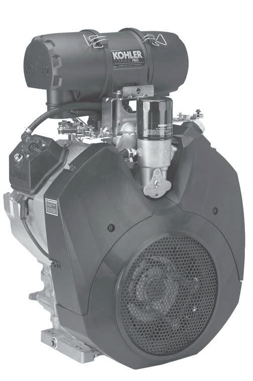
4 Air Cleaner Throttle Control Lever Oil Filter Choke Control Lever Carburetor Fuel Pump Oil Fill Spark Plug Dipstick Cylinder Shrouds Blower Housing Screen Electric Starter Figure 1. Typical Command PRO Horizontal Shaft Engine. Oil Drain Plugs Oil Recommendations Using the proper type and weight of oil in the crankcase is extremely important. So is checking oil daily and changing oil regularly. It is also recommended that a consistent brand of oil be used. Failure to use the correct oil, or using dirty oil, causes premature engine wear and failure. Oil Type Use high quality detergent oil of API (American Petroleum Institute) service class SG, SH, SJ or higher. Select the viscosity based on the air temperature at the time of operation as shown in the following table. Synthetic oils meeting the listed classifications may be used with oil changes performed at the recommended intervals. However to allow piston rings to properly seat, a new or rebuilt engine should be operated for at least 50 hours using standard petroleum based oil before switching to synthetic oil. A logo or symbol on oil containers identifies the API service class and SAE viscosity grade. See Figure 3. RECOMMENDED SAE VISCOSITY GRADES ** * 5W-20, 5W-30 10W-30 Kohler 10W-30 F C TEMPERATURE RANGE EXPECTED BEFORE NEXT OIL CHANGE * Use of synthetic oil having 5W-20 or 5W-30 rating is acceptable, up to 4 C (40 F) ** Synthetic oils will provide better starting in extreme cold below 23 C (-10 F) Figure 2. Viscosity Grades Table. Figure 3. Oil Container Logo. Refer to Maintenance Instructions beginning on page 8 for detailed oil check, oil change, and oil filter change procedures. Using other than service class SG, SH, SJ or higher oil or extending oil change intervals longer than recommended can cause engine damage. 4
5 Fuel Recommendations WARNING: Explosive Fuel! Gasoline is extremely flammable and its vapors can explode if ignited. Store gasoline only in approved containers, in well ventilated, unoccupied buildings, away from sparks or flames. Do not fill the fuel tank while the engine is hot or running, since spilled fuel could ignite if it comes in contact with hot parts or sparks from ignition. Do not start the engine near spilled fuel. Never use gasoline as a cleaning agent. General Recommendations Purchase gasoline in small quantities that can be used within 30 days and store only in clean, approved containers. Do not use gasoline left over from the previous season unless treated with a fuel stabilizer (see Storage), to minimize gum deposits and ensure easy starting. Do not use gasoline containing Methanol, or add oil to the gasoline. Do not overfill the fuel tank. Leave room for the fuel to expand. Fuel Type For best results use only clean, fresh, unleaded gasoline with a pump sticker octane rating of 87 or higher. In countries using the Research method, it should be 90 octane minimum. Unleaded gasoline is recommended as it leaves less combustion chamber deposits and reduces harmful exhaust emissions. Leaded gasoline is not recommended and must not be used in any models where exhaust emissions are regulated. Gasoline/Alcohol blends Gasohol (up to 10% ethyl alcohol, 90% unleaded gasoline by volume) is approved as a fuel for Kohler engines. Other gasoline/alcohol blends including E20 and E85 are not to be used and not approved. Any failures resulting from use of these fuels will not be warranted. Gasoline/Ether blends Methyl Tertiary Butyl Ether (MTBE) and unleaded gasoline blends (up to a maximum of 15% MTBE by volume) are approved as a fuel for Kohler engines. Other gasoline/ether blends are not approved. Engine Identification Numbers When ordering parts, or in any communication involving an engine, always give the Model, Specification, and Serial Numbers of the engine. Record your engine identification numbers on the identification label below (Figure 4) for future reference. Figure 4. Engine Identification Label. The Emission Compliance Period referred to on the Emission Control or Air Index label indicates the number of operating hours for which the engine has been shown to meet Federal emission requirements. The following table provides the Engine Compliance Period (in hours) associated with the category descriptor found on the certification label. Emission Compliance Period (Hours) Refer to certification label for engine displacement. Exhaust Emission Control System for models CH940- CH980 is EM. Model Designation Model CH980 for example: C designates Command engine, H designates horizontal crankshaft, and 980 indicates the numerical model designation. A letter suffix designates a specific version as follows: Suffix S IMPORTANT ENGINE INFORMATION THIS ENGINE MEETS EMISSION REGS FOR U.S. EPA PH 2 SMALL OFF ROAD ENGINES AND CA 2006 AND LATER LSI ENGINES FAMILY DISPL. (CC) MODEL NO. SPEC. NO. SERIAL NO. BUILD DATE OEM PROD. NO. EPA EMISSION COMPLIANCE PERIOD: EPA: CERTIFIED ON: REFER TO OWNER'S MANUAL FOR HP RATING, SAFETY, MAINTENANCE AND ADJUSTMENTS KOHLER CO. KOHLER, WISCONSIN USA Category A 1000 hours Designates Electric Start The engine identification numbers appear on a decal affixed to the engine shrouding. Include letter suffixes, if there are any. 5


6 Pre-Start Checklist Check oil level. Add oil if low. Do not overfill. Check fuel level. Add fuel if low. Operating Instructions Also read the operating instructions of the equipment this engine powers. Check cooling air intake areas and external surfaces of engine. Make sure they are clean and unobstructed. (B) (B) Check that the air cleaner components and all shrouds, equipment covers, and guards are in place and securely fastened. Check that any clutches or transmissions are disengaged or placed in neutral. This is especially important on equipment with hydrostatic drive. The shift lever must be exactly in neutral to prevent resistance which could keep the engine from starting. Throttle and Choke Control Linkage Setup The throttle and choke levers on these engines allow remote mounted control operation from either side. The linkage for the throttle and choke is connected in one of the two available hole locations; A or B in the control levers. Hole location A in each lever is used for Outer Pull actuation. Hole Location B used for Inner Pull actuation. Most engines will have the control linkage connected in Location A, the primary location. If the application requires opposite side control direction or function, unhook the link(s) from the small clip and reconnect in the other hole location. See Figures 5 and 6. Linkages Connected Here Figure 6. Throttle and Choke Control Linkage in "Inner Pull" Configuration. WARNING: Lethal Exhaust Gases! Engine exhaust gases contain poisonous carbon monoxide. Carbon monoxide is odorless, colorless, and can cause death if inhaled. Avoid inhaling exhaust fumes, and never run the engine in a closed building or confined area. Cold Weather Starting Hints 1. Be sure to use the proper oil for the temperature expected. See Figure 2 on page Disengage all possible external loads. 3. Be sure the battery is in good condition. A warm battery has much more starting capacity than a cold battery. 4. Use fresh winter grade fuel. Winter grade gasoline has higher volatility to improve starting. Do not use gasoline left over from summer. (A) (A) Starting 1. Place the throttle control midway between the slow and fast positions. Place the choke control into the on position. See Figures 7 and 8. Linkages Connected Here Figure 5. Throttle and Choke Control Linkage in "Outer Pull" Configuration. 6
. See your Kohler Engine Service Dealer for service assistance. Throttle Lever Figure 7. Location of Control Levers.")

7 If the starter does not turn the engine over, shut off starter immediately. Do not make further attempts to start the engine until the condition is corrected. Do not jump start using another battery (refer to Battery on this page). See your Kohler Engine Service Dealer for service assistance. Throttle Lever Figure 7. Location of Control Levers. Control Lever Knobs Choke Lever 3. For a Cold Engine Gradually return the choke control to the off position after the engine starts and warms up. The engine/equipment may be operated during the warm-up period, but it may be necessary to leave the choke partially on until the engine warms up. 4. For a Warm Engine Return choke to off position as soon as engine starts. Stopping 1. Remove the load by disengaging all PTO driven attachments. 2. Position the throttle control somewhere between half and full throttle; then stop the engine. Control Panel Figure 8. Optional Control Panel with Engine Mounted Controls. 2. Start the engine by activating the key switch. Release the switch as soon as the engine starts. Do not crank the engine continuously for more than 10 seconds at a time. If the engine does not start, allow a 60 second cool down period between starting attempts. Failure to follow these guidelines can burn out, or permanently damage, the starter motor. Upon start-up, a metallic ticking may occur. This is caused by hydraulic lifter leakdown during storage. Run the engine for 5 minutes. The noise will normally cease in the first minute. If noise continues, run the engine at mid-throttle for 20 minutes. If noise persists, take the engine to your local authorized Kohler Engine Service Dealer. Battery A 12 volt battery is normally used. Refer to the operating instructions of the equipment this engine powers for specific battery requirements. If the battery charge is not sufficient to crank the engine, recharge the battery (see page 13). Operating Angle of Operation This engine will operate continuously at angles up to 25. Check oil level to assure crankcase oil level is at the F mark on the dipstick. Refer to the operating instructions of the equipment this engine powers. Because of equipment design or application, there may be more stringent restrictions regarding the angle of operation. Do not operate this engine continuously at angles exceeding 25 in any direction. Engine damage could result from insufficient lubrication. If the engine develops sufficient speed to disengage the starter but does not keep running (a false start), engine rotation must be allowed to come to a complete stop before attempting to restart the engine. If the starter is engaged while the flywheel is rotating, the starter pinion and flywheel ring gear may clash resulting in damage to the starter. Cooling If debris builds up on the grass screen or other cooling air intake areas, stop the engine immediately and clean. Operating the engine with blocked or dirty air intake and cooling areas can cause extensive damage due to overheating. 7
8 WARNING: Hot Parts! Engine components can get extremely hot from operation. To prevent severe burns, do not touch these areas while the engine is running, or immediately after it is turned off. Never operate the engine with heat shields or guards removed. Engine Speed Do not tamper with the governor setting to increase the maximum engine speed. Overspeed is hazardous and will void the engine warranty. The maximum allowable high idle speed for these engines is 3900 RPM, no load. Maintenance Instructions Maintenance, repair, or replacement of the emission control devices and systems, which are being done at the customers expense, may be performed by any non-road engine repair establishment or individual. Warranty repairs must be performed by an authorized Kohler service outlet. WARNING: Accidental Starts! Disabling engine. Accidental starting can cause severe injury or death. Before working on the engine or equipment, disable the engine as follows: 1) Disconnect the spark plug lead(s). 2) Disconnect negative (-) battery cable from battery. Maintenance Schedule These required maintenance procedures should be performed at the frequency stated in the table. They should also be included as part of any seasonal tune-up. Frequency Daily or Before Starting Engine Weekly Seasonally or Every 150 Hours Every 200 Hours Seasonally or Every 300 Hours Yearly or Every 500 Hours Maintenance Fill fuel tank. Check oil level. Check air cleaner for dirty 1, loose, or damaged parts. Check air intake and cooling areas, clean as necessary. Check filter minder or air cleaner element. Check air cleaner element. Replace fuel filter. Change oil. Oil filter is recommended. (More frequently under severe conditions.) Remove cooling shrouds and clean cooling areas 1. Check oil cooler fins, clean as necessary. Check spark plug condition and gap. Change oil filter. Replace air cleaner element. Have solenoid shift starter disassembled and cleaned. Have crankshaft splines lubricated 2. Replace inner air cleaner element. Every 600 Hours Replace spark plugs. 1 Perform these maintenance procedures more frequently under extremely dusty, dirty conditions. 2 Have a Kohler Engine Service Dealer perform this service. Check Oil Level The importance of checking and maintaining the proper oil level in the crankcase cannot be overemphasized. Check oil BEFORE EACH USE as follows: 1. Make sure the engine is stopped, level, and is cool so the oil has had time to drain into the sump. 2. To keep dirt, debris, etc., out of the engine, clean the area around the dipstick before removing it. 3. Remove the dipstick; wipe oil off. Reinsert the dipstick into the tube and press all the way down. 8


9 Oil Fill Pressure Switch Dipstick Figure 9. Dipstick and Oil Fill. Figure 11. Oil Sentry Pressure Switch. 4. Remove the dipstick and check the oil level. The oil level should be up to, but not over, the F mark on the dipstick. See Figure 10. Make sure the oil level is checked BEFORE EACH USE and is maintained up to the F mark on the dipstick. This includes engines equipped with Oil Sentry systems. Change Oil and Filter, Service Oil Cooler Figure 10. Oil Level Marks on Dipstick. 5. If the level is low, remove the cap from the valve cover and add oil of the proper type, up to the F mark on the dipstick. (Refer to Oil Type on page 4.) Always check the level with the dipstick before adding more oil. Operating Range To prevent extensive engine wear or damage, always maintain the proper oil level in the crankcase. Never operate the engine with the oil level below the L mark or over the F mark on the dipstick. Oil Sentry Most engines are equipped with an Oil Sentry oil pressure switch. On pressure switch equipped models, if the oil pressure decreases below an acceptable level, the Oil Sentry will either shut off the engine or activate a warning signal, depending on the application. See Figure 11. Change Oil Change oil seasonally or every 150 hours of operation, (more frequently under severe conditions). Refill with service class SG, SH, SJ or higher oil as specified in the Viscosity Grades table (Figure 2) on page 4. Change the oil while the engine is still warm. The oil will flow more freely and carry away more impurities. Make sure the engine is level when filling, checking, and changing the oil. Change the oil as follows (see Figures 12 and 13): 1. To keep dirt, debris, etc., out of the engine, clean the area around the oil fill cap, dipstick and one of the drain plugs. 2. Remove one of the oil drain plugs, oil fill cap, and dipstick. Be sure to allow ample time for complete drainage. 3. Reinstall the drain plug. Make sure it is tightened to 21.4 N m (15.7 ft. lb.) torque. 4. Fill the crankcase, with new oil of the proper type, to the F mark on the dipstick. Refer to Oil Type on page 4. Always check the level with the dipstick before adding more oil. 5. Reinstall the oil fill cap and tighten securely. Reinstall dipstick. 9
. Replace the oil filter as follows: 1.")


. 5. Apply a thin film of clean oil to the rubber gasket on the new filter. 6. Install the replacement oil filter.")
10 To prevent extensive engine wear or damage, always maintain the proper oil level in the crankcase. Never operate the engine with the oil level below the L mark or over the F mark on the dipstick. Figure 15. Optional Remote Mounted Oil Filter. Drain Plug Figure 12. Oil Drain Plug (Starter Side). Replace the oil filter as follows: 1. Before removing the oil filter, clean the area around the oil filter and housing to keep dirt and debris out of the engine. Remove the old filter. On crankcase mounted oil filter housings, a spring loaded inner cup allows automatic oil drainback into the crankcase as the oil filter is removed. Wipe off the surface where the oil filter mounts. 2. Drain the oil from the engine crankcase. 3. Allow ample time for the oil to drain from the crankcase. Drain Plug Figure 13. Oil Drain Plug (No. 2 Side). Change Oil Filter The oil filter on most engines is located on top of the crankcase between the cylinders. Some models use a remote mounted oil filter. See Figures 14 and 15. Replace the oil filter seasonally (150 hours), or at least every other oil change (every 300 hours of operation). Always use a genuine Kohler oil filter, Part No S. Oil Filter 4. Reinstall the drain plug and torque to 21.4 N m (15.7 ft. lb.). 5. Apply a thin film of clean oil to the rubber gasket on the new filter. 6. Install the replacement oil filter. Turn the oil filter clockwise until the rubber gasket contacts the oil filter housing (not inner cup), then tighten the filter an additional 3/4 to 1 turn. 7. Fill the crankcase with new oil of the proper type to the F mark on the dipstick. 8. Start the engine and check for oil leaks. Correct any leaks before placing the engine into service. Check oil level to be sure it is up to but not over the F mark. Service Oil Cooler Engines are equipped with an oil cooler mounted under the No. 2 side cylinder shroud, separate from the oil filter (see Figure 16). Figure 14. Engine Mounted Oil Filter. 10 Oil Filter Housing


, unhook the two retaining clips on each end and remove the end caps.")
11 Inspect and clean the oil cooler every 150 hours of operation (more frequently under severe conditions). Oil cooler must be kept free of debris. To access and service the oil cooler, remove the top mounting screw and loosen the two side screws, then lift off the No. 2 side cylinder shroud. If required, remove the two screws holding the oil cooler to the blower housing. Pull the cooler away from the blower housing. Clean both sides of the cooler with a brush as shown in Figures 17 and 18, or with compressed air. After cleaning, reattach the oil cooler to the lower blower housing with the two mounting screws. Air Cleaners General These engines use a heavy-duty style air cleaner shown in Figure 19, consisting of a cylindrical housing mounted to the carburetor and intake manifold. The air cleaner housing contains a paper element and inner element, designed for longer service intervals. The system is CARB/EPA certified and the components should not be altered or modified in any way. Oil Cooler Figure 19. Heavy-Duty Style Air Cleaner. Figure 16. Oil Cooler. Service Weekly and every 150 hours: Check filter minder (if equipped), unhook the two retaining clips on each end and remove the end caps. Perform inspection of the paper element and inlet screen area. Seasonally or every 300 hours of operation (more often under extremely dusty or dirty conditions), replace the paper element and check the inner element. Follow these steps. 1. Unhook the two retaining clips on each end and remove the end caps from the air cleaner housing. Figure 17. Cleaning Top of Oil Cooler. 2. Check and clean the screen area on the inlet side. Pull the air cleaner paper element out of the housing on opposite side. See Figures 20 and 21. Figure 18. Cleaning Underside of Oil Cooler. Inlet Screen Figure 20. Accessing Inlet Screen. 11


12 Paper Element Clean Air Intake/Cooling Areas To ensure proper cooling, make sure the grass screen, cooling fins, and other external surfaces of the engine are kept clean at all times. Operating the engine with a blocked grass screen, dirty or plugged cooling fins, and/or cooling shrouds removed, will cause engine damage due to overheating. Figure 21. Removing Elements. Inner Element 3. After the paper element is removed, check the condition of the inner element. It should be replaced whenever it appears dirty, typically every other time the paper element is replaced or every 600 hours. Clean the area around the base of the inner element before removing it, so dirt does not get into the engine. 4. Do not wash the paper element and inner element or use compressed air, this will damage the elements. Replace dirty, bent or damaged elements with new genuine Kohler elements as required. Handle the new elements carefully; do not use if the sealing surfaces are bent or damaged. 5. Check all parts for wear, cracks, or damage, and make sure ejector area is clean. See Figure 22. Replace any damaged components. Ignition System An electronic Capacitive Discharge (CD) ignition system is used. Other than periodically checking/ replacing the spark plugs, no maintenance, timing, or adjustments are necessary or possible with this system. Check Spark Plugs Every 200 hours of operation, remove the spark plugs, check condition, and reset the gap. Replace with new plugs every 600 hours, or as necessary. The standard spark plug is a Champion XC10YC (Kohler Part No S). Equivalent alternate brand plugs can also be used. 1. Before removing the spark plug, clean the area around the base of the plug to keep dirt and debris out of the engine. 2. Remove the plug and check its condition. Replace the plug if worn or reuse is questionable. Do not clean the spark plug in a machine using abrasive grit. Some grit could remain in the spark plug and enter the engine causing extensive wear and damage. 3. Check the gap using a wire feeler gauge. Adjust the gap to 0.76 mm (0.030 in.) by carefully bending the ground electrode. See Figure 23. Ejector Area Wire Gauge Spark Plug Figure 22. Ejector Area Install the new inner element, Kohler Part No S followed by the paper element, Part No S. Slide each fully into place in the air cleaner housing. 7. Reinstall the end caps and secure with the retaining clips. See Figure 19. Ground Electrode Figure 23. Servicing Spark Plug mm (0.030 in.) Gap

13 4. Reinstall the spark plug into the cylinder head. Torque the spark plug to N m (18-22 ft. lb.). Battery Charging WARNING: Explosive Gas! Batteries produce explosive hydrogen gas while being charged. To prevent a fire or explosion, charge batteries only in well ventilated areas. Keep sparks, open flames, and other sources of ignition away from the battery at all times. Keep batteries out of the reach of children. Remove all jewelry when servicing batteries. Before disconnecting the negative (-) ground cable, make sure all switches are OFF. If ON, a spark will occur at the ground cable terminal which could cause an explosion if hydrogen gas or gasoline vapors are present. Fuel System Do not apply 12 volt DC to kill terminal of ignition module. Fuel Filter Most engines are equipped with an in-line fuel filter. Periodically inspect the filter and replace with a genuine Kohler filter seasonally or every 150 operating hours. Carburetor Troubleshooting and Adjustments These engines use a Keihin BK two-barrel carburetor with fixed main jets, and fixed or limiter-equipped low idle fuel adjusting needles. See Figure 25. In compliance with government emission standards, the carburetor is calibrated to deliver the correct fuel-toair mixture to the engine under all operating conditions. Adjustments are made as follows. Idle Fuel Adjustments Drain Screw Figure 25. Keihin Two-Barrel Carburetor. Vacuum Port Idle Speed (RPM) Adjustment Screw Carburetor adjustments should be made only after the engine has warmed up. Fuel Line These engines use Low Permeation SAE 30 R7 rated fuel line; certified to meet emission requirements. Standard fuel line may not be used. Order replacement hose by part number through a Kohler Engine Service Dealer. To ensure correct engine operation at altitudes above 1525 meters (5000 ft.), it may be necessary to have an authorized Kohler dealer install a special high-altitude jet kit in the carburetor. If a high-altitude kit has been installed, the engine must be reconverted to the original jet size, before it is operated at lower altitudes, or overheating and engine damage can result. Troubleshooting If engine troubles are experienced that appear to be fuel system related, check the following areas before adjusting the carburetor. Make sure the fuel tank is filled with clean, fresh gasoline. Make sure the fuel tank cap vent is not blocked and that it is operating properly. Figure 24. Low Permeation Fuel Line. If the fuel tank is equipped with a shut-off valve, make sure it is open. If the engine is equipped with an in-line fuel filter, make sure it is clean and unobstructed. Replace the filter if necessary. 13

 and Governed Idle Adjustment 1. Low Idle Speed (RPM) Setting: Place the throttle control into the idle or slow position.")
 by turning the low idle speed adjusting screw on carburetor in or out. Check the speed using a tachometer.")
14 Make sure fuel is reaching the carburetor. This includes checking the fuel lines and fuel pump for restrictions or faulty components, replace as necessary. Make sure the air cleaner element is clean and all air cleaner element components are fastened securely. If, after checking the items listed above, the engine is hard to start, runs roughly, or stalls at low idle speed, it may be necessary to adjust or service the carburetor. Adjust Carburetor Low Idle Speed (RPM) and Governed Idle Adjustment 1. Low Idle Speed (RPM) Setting: Place the throttle control into the idle or slow position. Hold the governor lever away from carburetor so the throttle lever is against the Idle Speed (RPM) Adjustment Screw of carburetor. See Figure 25. Set the low idle speed to 1200 RPM* (± 75 RPM) by turning the low idle speed adjusting screw on carburetor in or out. Check the speed using a tachometer. * The actual low idle speed depends on the application. Refer to the equipment manufacturer s recommendations. The low idle speed for basic engines is 1200 RPM. To ensure best results when setting the low idle fuel needle, the low idle speed should be 1200 RPM (± 75 RPM). 2. Release the governor lever and check that the throttle lever is in the idle position. Turn the governed idle (outer) adjustment screw on main control bracket to obtain the equipment manufacturer's recommended idle speed ( RPM). See Figure 26. Low Idle Fuel Adjustment Engines will have fixed low idle or limiter caps on the two idle fuel adjusting needles. Step 3 can only be performed within the limits allowed by the cap. Do not attempt to remove the limiter caps. 1. Start the engine and run at half throttle for 5 to 10 minutes to warm up. The engine must be warm before doing steps 2, 3 and Place the throttle control into the idle or slow position. Adjust the low idle speed to 1200 RPM*. Follow the Adjusting the Low Idle Speed (RPM) procedure. 3. Low Idle Fuel Needle(s) Setting: Place the throttle into the idle or slow position. a. Turn one of the low idle fuel adjusting needles out (counterclockwise) from the preliminary setting until the engine speed decreases (rich). Note the position of the needle. Now turn the adjusting needle in (clockwise). The engine speed may increase, then it will decrease as the needle is turned in (lean). Note the position of the needle. Set the adjusting needle midway between the rich and lean settings. See Figure 27. b. Repeat the procedure on the other low idle adjustment needle. 4. Recheck/adjust the Low Idle Speed (RPM), to the specified setting. Adjust to Midpoint Lean Adjust to Midpoint Lean Governed Idle Speed Screw Rich Rich Left Side Right Side Figure 27. Optimum Low Idle Fuel Settings. High Speed Adjustment Screw Figure 26. Adjusting Governed Idle Speed Screw. High Speed (RPM) Adjustment The high speed RPM (inner) adjustment screw is preset at the factory and normally does not need readjustment. 14
15 Troubleshooting When troubles occur, be sure to check the simple causes which, at first, may seem too obvious to be considered. For example, a starting problem could be caused by an empty fuel tank. Some common causes of engine troubles are listed in the following table. Do not attempt to service or replace major engine components, or any items that require special timing or adjustment procedures. Have your Kohler Engine Service Dealer do this work. Possible Cause No Improper Dirt In Dirty Incorrect Engine Dirty Air Faulty Problem Fuel Fuel Fuel Line/System Grass Screen Oil Level Overloaded Cleaner Spark Plug Will Not Start Hard Starting Stops Suddenly Lacks Power Operates Erratically Knocks or Pings Skips or Misfires Backfires Overheats High Fuel Consumption Storage If the engine will be out of service for 30 days or more, use the following storage procedure: 1. Clean the exterior surfaces of the engine. Avoid spraying water at the wiring harness or any of the electrical components. 2. Change the oil and filter while the engine is still warm from operation. See Change Oil and Change Oil Filter on pages 9 and The fuel system must be completely emptied, or the gasoline must be treated with a stabilizer to prevent deterioration. If you choose to use a stabilizer, follow the manufacturer s recommendations, and add the correct amount for the capacity of the fuel system. Fill the fuel tank with clean, fresh gasoline. Run the engine for 2-3 minutes to get stabilized fuel into the rest of the system. Close fuel shut-off valve when unit is being stored or transported. To empty the system, run the engine until the tank and fuel system are empty. 4. Remove the spark plugs. Add one tablespoon of engine oil into each spark plug hole. Install the plugs, but do not connect the plug leads. Crank the engine two or three revolutions. Parts Ordering The engine Specification, Model, and Serial Numbers are required when ordering replacement parts from your Kohler Engine Service Dealer. These numbers are found on the identification plate which is affixed to the engine shrouding. Include letter suffixes if there are any. See Engine Identification Numbers on page 5. Always insist on genuine Kohler parts. All genuine Kohler parts meet strict standards for fit, reliability, and performance. Major Repair Major repair information is available in Kohler Engine Service Manuals. This type of repair generally requires the services of a trained mechanic and the use of special tools and equipment. Kohler Engine Service Dealers have the facilities, training, and genuine Kohler replacement parts necessary to perform this service. For the nearest Sales & Service location: visit our website call (U.S. & Canada) look in the yellow pages under Engines-Gasoline 5. Store the engine in a clean, dry place. 15
16 Specifications Model:... CH CH CH980 Bore:... mm (in.) (3.54) (3.54) (3.54) Stroke:... mm (in.) (3.1) (3.1) (3.1) Displacement:... cm 3 (in 3 ) (61) (61) (61) Power (@3600 RPM):... kw (HP) (34*) (36*) (38*) Compression Ratio: : : :1 Weight:... kg (lb.) (132) (132) (132) Oil Capacity (w/filter) - approximate, determined by oil filter used: 2.7 L (2.9 U.S. qt.) Lubrication: Full Pressure w/full Flow Filter Exhaust Emission Control System for models CH940-CH980 is EM. *Horsepower ratings exceed Society of Automotive Engineers Small Engine Test Code J1940. Actual engine horsepower is lower and affected by, but not limited to, accessories (air cleaner, exhaust, charging, cooling, fuel pump, etc.), application, engine speed and ambient operating conditions (temperature, humidity, and altitude). Kohler reserves the right to change product specifications, designs and equipment without notice and without incurring obligation. LIMITED 2 YEAR COMMAND PRO ENGINE WARRANTY Kohler Co. warrants to the original consumer that each new COMMAND PRO engine sold by Kohler Co. will be free from manufacturing defects in materials or workmanship in normal service for a period of two (2) years from date of purchase, provided it is operated and maintained in accordance with Kohler Co. s instructions and manuals. Our obligation under this warranty is expressly limited, at our option, to the replacement or repair at Kohler Co., Kohler, Wisconsin 53044, or at a service facility designated by us of such parts as inspection shall disclose to have been defective. EXCLUSIONS Mufflers on engines used commercially (non-residential) are warranted for one (1) year from date of purchase, except catalytic mufflers, which are warranted for two (2) years. This warranty does not apply to defects caused by casualty or unreasonable use, including faulty repairs by others and failure to provide reasonable and necessary maintenance. The following items are not covered by this warranty: Engine accessories such as fuel tanks, clutches, transmissions, power-drive assemblies, and batteries, unless supplied or installed by Kohler Co. These are subject to the warranties, if any, of their manufacturers. KOHLER CO. AND/OR THE SELLER SHALL NOT BE LIABLE FOR SPECIAL, INDIRECT, INCIDENTAL, OR CONSEQUENTIAL DAMAGES OF ANY KIND, including but not limited to labor costs or transportation charges in connection with the repair or replacement of defective parts. IMPLIED OR STATUTORY WARRANTIES, INCLUDING WARRANTIES OF MERCHANTABILITY OR FITNESS FOR A PARTICULAR PURPOSE, ARE EXPRESSLY LIMITED TO THE DURATION OF THIS WRITTEN WARRANTY. We make no other express warranty, nor is any one authorized to make any on our behalf. Some states do not allow limitations on how long an implied warranty lasts, or the exclusion or limitation of incidental or consequential damages, so the above limitation or exclusion may not apply to you. This warranty gives you specific legal rights, and you may also have other rights which vary from state to state. TO OBTAIN WARRANTY SERVICE Purchaser must bring the engine to an authorized Kohler service facility. To locate the nearest facility, visit our website, and click on SALES AND SERVICES to use the locator function, consult your Yellow Pages or telephone ENGINE DIVISION, KOHLER CO., KOHLER, WISCONSIN
17 KOHLER CO. FEDERAL AND CALIFORNIA EMISSION CONTROL SYSTEMS LIMITED WARRANTY SMALL OFF-ROAD AND CLASS 1 LSI ENGINES The U.S. Environmental Protection Agency (EPA), the California Air Resources Board (CARB), and Kohler Co. are pleased to explain the Federal and California Emission Control Systems Warranty on your off-road equipment engine. For California, small off-road engines produced in 1995 and later, and Class 1 LSI (Large Spark Ignited engines at or below 1.0 liter) produced in 2002 and later, must be designed, built and equipped to meet the state s stringent anti-smog standards. In other states, 1997 and later model year engines must be designed, built and equipped, to meet the U.S. EPA regulations for small non-road engines. The engine must be free from defects in materials and workmanship, which cause it to fail to conform with U.S. EPA standards for the first two years of engine use from the date of sale to the ultimate purchaser. Kohler Co. must warrant the emission control system on the engine for the period of time listed above, provided there has been no abuse, neglect or improper maintenance. The emission control system may include parts such as the carburetor or fuel injection system, the ignition system, and catalytic converter. Also included are the hoses, belts and connectors and other emission related assemblies. Where a warrantable condition exists, Kohler Co. will repair the engine at no cost, including diagnosis (if the diagnostic work is performed at an authorized dealer), parts and labor. MANUFACTURER S WARRANTY COVERAGE Small off-road engines produced in 1995 or later, and Class 1 LSI engines produced in 2002 and later, are warranted for two years in California. In other states, 1997 and later model year engines are warranted for two years. If any emission related part on the engine is defective, the part will be repaired or replaced by Kohler Co. free of charge. OWNER S WARRANTY RESPONSIBILITIES (a) The engine owner is responsible for the performance of the required maintenance listed in the owner s manual. Kohler Co. recommends that you retain all receipts covering maintenance on the engine, but Kohler Co. cannot deny warranty solely for the lack of receipts or for your failure to assure that all scheduled maintenance was performed. (b) (c) Be aware, however, that Kohler Co. may deny warranty coverage if the engine or a part has failed due to abuse, neglect, improper maintenance or unapproved modifications. For warranty repairs, the engine must be presented to a Kohler Co. service center as soon as a problem exists. Call or access our website at: for the names of the nearest service centers. The warranty repairs should be completed in a reasonable amount of time, not to exceed 30 days. If you have any questions regarding warranty rights and responsibilities, you should contact Kohler Co. at and ask for an Engine Service representative. COVERAGE Kohler Co. warrants to the ultimate purchaser and each subsequent purchaser that the engine will be designed, built and equipped, at the time of sale, to meet all applicable regulations. Kohler Co. also warrants to the initial purchaser and each subsequent purchaser, that the engine is free from defects in materials and workmanship which cause the engine to fail to conform with applicable regulations for a period of two years. Small off-road engines produced in 1995 or later, and Class 1 LSI engines produced in 2002 and later, are warranted for two years in California. For 1997 and later model years, EPA requires manufacturers to warrant engines for two years in all other states. These warranty periods will begin on the date the engine is purchased by the initial purchaser. If any emission related part on the engine is defective, Kohler Co. will replace the part at no cost to the owner. Kohler Co. is liable for damages to other engine components caused by the failure of a warranted part still under warranty. Kohler Co. shall remedy warranty defects at any authorized Kohler Co. engine dealer or warranty station. Warranty repair work done at an authorized dealer or warranty station shall be free of charge to the owner if such work determines that a warranted part is defective. Listed below are the parts covered by the Federal and California Emission Control Systems Warranty. Some parts listed below may require scheduled maintenance and are warranted up to the first scheduled replacement point for that part. The warranted parts are: Carburetor assembly Throttle body (EFI Systems) Catalytic muffler (if equipped) Fuel metering valve (if equipped) Crankcase breather Fuel pressure regulator (EFI Systems) Ignition module(s) with high tension lead Spark advance module (if equipped) Oxygen, speed, throttle position, and temperature sensors (if equipped) Electronic control unit (if equipped) Fuel injectors (EFI Systems) Air filter, fuel filter, and spark plugs (only to first scheduled replacement point) Continued on next page. 17
18 LIMITATIONS This Emission Control Systems Warranty shall not cover any of the following: (a) (b) (c) (d) (e) repair or replacement required because of misuse or neglect, improper maintenance, repairs improperly performed or replacements not conforming to Kohler Co. specifications that adversely affect performance and/or durability and alterations or modifications not recommended or approved in writing by Kohler Co., replacement of parts and other services and adjustments necessary for required maintenance at and after the first scheduled replacement point, consequential damages such as loss of time, inconvenience, loss of use of the engine or equipment, etc., diagnosis and inspection fees that do not result in eligible warranty service being performed, and any add-on or modified part, or malfunction of authorized parts due to the use of add-on or modified parts. MAINTENANCE AND REPAIR REQUIREMENTS The owner is responsible for the proper use and maintenance of the engine. Kohler Co. recommends that all receipts and records covering the performance of regular maintenance be retained in case questions arise. If the engine is resold during the warranty period, the maintenance records should be transferred to each subsequent owner. Kohler Co. reserves the right to deny warranty coverage if the engine has not been properly maintained; however, Kohler Co. may not deny warranty repairs solely because of the lack of repair maintenance or failure to keep maintenance records. Normal maintenance, replacement or repair of emission control devices and systems may be performed by any repair establishment or individual; however, warranty repairs must be performed by a Kohler authorized service center. Any replacement part or service that is equivalent in performance and durability may be used in non-warranty maintenance or repairs, and shall not reduce the warranty obligations of the engine manufacturer. 18
19 19
20 FORM NO.: ISSUED: 1/07 REVISED: 8/07 LITHO IN U.S.A. FOR SALES AND SERVICE INFORMATION IN U.S. AND CANADA, CALL KohlerEngines.com ENGINE DIVISION, KOHLER CO., KOHLER, WISCONSIN 53044
CH940-CH1000 CV940-CV1000 Owner's Manual
 CH940-CH1000 CV940-CV1000 Owner's Manual IMPORTANT: Read all safety precautions and instructions carefully before operating equipment. Refer to operating instruction of equipment that this engine powers.
CH682, CH732, CH742, CH752 CV682, CV732, CV742, CV752 Owner's Manual
 EN ESS CH682, CH732, CH742, CH752 CV682, CV732, CV742, CV752 Owner's Manual FRC IMPORTANT: Read all safety precautions and instructions carefully before operating equipment. Refer to operating instruction
OWNER'S MANUAL COMMAND PRO CH940-CH1000 HORIZONTAL CRANKSHAFT
 OWNER'S MANUAL COMMAND PRO CH940-CH1000 HORIZONTAL CRANKSHAFT 1 Safety Precautions To ensure safe operations please read the following statements and understand their meaning. Also refer to your equipment
SV471-SV601 Owner's Manual
 EN ESS SV471-SV601 Owner's Manual FRC IMPORTANT: Read all safety precautions and instructions carefully before operating equipment. Refer to operating instruction of equipment that this engine powers.
KT715-KT745 Owner's Manual
 EN KT715-KT745 Owner's Manual ESS FRC IMPORTANT: Read all safety precautions and instructions carefully before operating equipment. Refer to operating instruction of equipment that this engine powers.
EZT715-EZT750 Owner's Manual
 EN EZT715-EZT750 Owner's Manual ESS FRC IMPORTANT: Read all safety precautions and instructions carefully before operating equipment. Refer to operating instruction of equipment that this engine powers.
ZT710-ZT740 Owner's Manual
 EN ZT710-ZT740 Owner's Manual ESS FRC IMPORTANT: Read all safety precautions and instructions carefully before operating equipment. Refer to operating instruction of equipment that this engine powers.
ECV850, ECV860, ECV870, ECV880 Owner's Manual
 EN ESS ECV850, ECV860, ECV870, ECV880 Owner's Manual FRC IMPORTANT: Read all safety precautions and instructions carefully before operating equipment. Refer to operating instruction of equipment that this
KS530-KS595 Owner's Manual
 EN ESS KS530-KS595 Owner's Manual FRC IMPORTANT: Read all safety precautions and instructions carefully before operating equipment. Refer to operating instruction of equipment that this engine powers.
KOHLER TRIAD OHC TH520-TH650 HORIZONTAL CRANKSHAFT OWNER'S MANUAL
 KOHLER TRIAD OHC TH520-TH650 HORIZONTAL CRANKSHAFT OWNER'S MANUAL 1 Safety Precautions To ensure safe operations please read the following statements and understand their meaning. Also refer to your equipment
CH23, CH620-CH740, CH750 CV23, CV620-CV740, CV750 Owner's Manual
 EN CH23, CH620-CH740, CH750 CV23, CV620-CV740, CV750 Owner's Manual ESS FRC IMPORTANT: Read all safety precautions and instructions carefully before operating equipment. Refer to operating instruction
HD675, HD775 Owner's Manual
 EN ESS HD675, HD775 Owner's Manual FRC IMPORTANT: Read all safety precautions and instructions carefully before operating equipment. Refer to operating instruction of equipment that this engine powers.
MAGNUM 18 & 20 HP HORIZONTAL CRANKSHAFT
 MAGNUM 18 & 20 HP HORIZONTAL CRANKSHAFT OWNER'S MANUAL Safety Precautions To ensure safe operations please read the following statements and understand their meaning. Also refer to your equipment owner's
OWNER'S MANUAL COURAGE SERIES SV470, SV480, SV530, SV540, SV590, SV600 VERTICAL CRANKSHAFT
 OWNER'S MANUAL COURAGE SERIES SV470, SV480, SV530, SV540, SV590, SV600 VERTICAL CRANKSHAFT Safety Precautions To ensure safe operation please read the following statements and understand their meaning.
Safety Precautions To insure safe operations please read the following statements and understand their meaning Also refer to your equipment owner's ma
 MAGNUM 18 & 20 HP HORIZONTAL CRANKSHAFT OWNER'S MANUAL 1 Safety Precautions To insure safe operations please read the following statements and understand their meaning Also refer to your equipment owner's
ECH940 & ECH980, ECV940 & ECV980 Owner's Manual
 EN ESS FRC ECH940 & ECH980, ECV940 & ECV980 Owner's Manual IMPORTANT: Read all safety precautions and instructions carefully before operating equipment. Refer to operating instruction of equipment that
VERTICAL CRANKSHAFT OWNER'S MANUAL COURAGE SV
 VERTICAL CRANKSHAFT OWNER'S MANUAL COURAGE SV470-610 Safety Precautions To ensure safe operation please read the following statements and understand their meaning. Also refer to your equipment owner's
KT610-KT620, KT715-KT745 Owner's Manual
 EN ESS FRC KT610-KT620, KT715-KT745 Owner's Manual IMPORTANT: Read all safety precautions and instructions carefully before operating equipment. Refer to operating instruction of equipment that this engine
XTX650, XTX675, XTX775, XTX950, XTX1100 Owner's Manual
 EN ESS XTX650, XTX675, XTX775, XTX950, XTX1100 Owner's Manual FRC IMPORTANT: Read all safety precautions and instructions carefully before operating equipment. Refer to operating instruction of equipment
ECH630-ECH749, CH735/CH26, CH745 ECV630-ECV749, CV735, CV745 Owner's Manual
 EN ESS ECH630-ECH749, CH735/CH26, CH745 ECV630-ECV749, CV735, CV745 Owner's Manual FRC IMPORTANT: Read all safety precautions and instructions carefully before operating equipment. Refer to operating instruction
SH255, SH265 Owner's Manual
 EN DE SH255, SH265 Owner's Manual ESE ESS FRC FRF HR ID IT PT RO RU SL TR ZH IMPORTANT: Read all safety precautions and instructions carefully before operating equipment. Refer to operating instruction
LH640, LH685, LH690 Owner's Manual
 LH640, LH685, LH690 Owner's Manual IMPORTANT: Read all safety precautions and instructions carefully before operating equipment. Refer to operating instruction of equipment that this engine powers. Ensure
SERVICE MANUAL COMMAND CV11-16, CV , CV VERTICAL CRANKSHAFT
 COMMAND CV-6, CV460-465, CV490-495 SERVICE MANUAL VERTICAL CRANKSHAFT Section CV-6 Safety and CV460-465, General Information CV490-495 Section Safety Precautions To insure safe operations please read the
OWNER'S MANUAL COMMAND HP HORIZONTAL CRANKSHAFT
 OWNER'S MANUAL COMMAND 11-16 HP HORIZONTAL CRANKSHAFT 1 Safety Precautions To insure safe operations please read the following statements and understand their meaning. Also refer to your equipment owner's
VERTICAL CRANKSHAFT OWNER'S MANUAL COURAGE SV470-SV620
 VERTICAL CRANKSHAFT OWNER'S MANUAL COURAGE SV470-SV620 Safety Precautions To ensure safe operation please read the following statements and understand their meaning. Also refer to your equipment owner's
OWNER'S MANUAL KOHLER AEGIS LV625, LV675, LV680 LIQUID-COOLED VERTICAL CRANKSHAFT
 OWNER'S MANUAL KOHLER AEGIS LV625, LV675, LV680 LIQUID-COOLED VERTICAL CRANKSHAFT Safety Precautions To ensure safe operations please read the following statements and understand their meaning. Also refer
WARRANTY LIMITED WARRANTY, COMMAND PRO. . Print
 WARRANTY Command PRO LIMITED WARRANTY, COMMAND PRO Email Print Kohler Co. warrants to the original retail consumer that each new engine will be free from manufacturing defects in materials or workmanship
Draft. Proprietary Photo. Record Engine Information to reference when ordering parts or obtaining warranty coverage. Engine Model.
 Engine Model XXxxxx Liquefied Petroleum Gas (LPG) or LPG / Natural Gas (NG) Fueled Operation Manual TP-6901 Important: Proprietary Photo Read all safety precautions and instructions carefully before operating
CH260, CH270, CH395, CH440 Owner's Manual
 EN DA CH260, CH270, CH395, CH440 Owner's Manual DE ESE ESS FRC FRF HR ID IT KO NL PL PT RO RU SL ZH IMPORTANT: Read all safety precautions and instructions carefully before operating equipment. Refer to
LH775 Owner's Manual. Record engine information to reference when ordering parts or obtaining warranty coverage.
 LH775 Owner's Manual IMPORTANT: Read all safety precautions and instructions carefully before operating equipment. Refer to operating instruction of equipment that this engine powers. Ensure engine is
OWNER'S MANUAL COMMAND PRO CS SERIES 4-12 HP HORIZONTAL CRANKSHAFT
 OWNER'S MANUAL COMMAND PRO CS SERIES 4-12 HP HORIZONTAL CRANKSHAFT 1 Safety Precautions To insure safe operations please read the following statements and understand their meaning. Also refer to your equipment
EKT735-EKT750 Owner's Manual
 EN ESS FRC EKT735-EKT750 Owner's Manual IMPORTNT: Read all safety precautions and instructions carefully before operating equipment. Refer to operating instruction of equipment that this engine powers.
LH775 Owner's Manual. Record engine information to reference when ordering parts or obtaining warranty coverage.
 EN ESS LH775 Owner's Manual FRC IMPORTANT: Read all safety precautions and instructions carefully before operating equipment. Refer to operating instruction of equipment that this engine powers. Ensure
VERTICAL CRANKSHAFT OWNER'S MANUAL COURAGE SV COURAGE PRO SV
 VERTICAL CRANKSHAFT OWNER'S MANUAL COURAGE SV710-740 COURAGE PRO SV810-840 Safety Precautions To ensure safe operation please read the following statements and understand their meaning. Also refer to your
ECH440, ECH440LE Owner's Manual
 EN DA DE ECH440, ECH440LE Owner's Manual ESE ESS FRC FRF HR ID IT KO NL PL PT RO RU SL ZH IMPORTANT: Read all safety precautions and instructions carefully before operating equipment. Refer to operating
PCH680, PCH740 PCV680, PCV740
 PCH680, PCH740 PCV680, PCV740 Propane Electronic Fuel Injection (EFI) Owner's Manual IMPORTANT: Read all safety precautions and instructions carefully before operating equipment. Refer to operating instruction
CH640, CH730, CH740. Liquefi ed Petroleum Gas (LPG) or LPG/Natural Gas (NG) Fueled Owner's Manual
 or LPG/Natural Gas (NG) Fueled Owner's Manual") CH640, CH730, CH740 Liquefi ed Petroleum Gas (LPG) or LPG/Natural Gas (NG) Fueled Owner's Manual IMPORTANT: Read all safety precautions and instructions carefully before operating equipment. Refer to operating
CH640, CH730, CH740 Liquefi ed Petroleum Gas (LPG) or LPG/Natural Gas (NG) Fueled Owner's Manual IMPORTANT: Read all safety precautions and instructions carefully before operating equipment. Refer to operating
KT610-KT620, KT715-KT745 Owner's Manual
 EN ESS FRC KT610-KT620, KT715-KT745 Owner's Manual IMPORTNT: Read all safety precautions and instructions carefully before operating equipment. Refer to operating instruction of equipment that this engine
PF-4000, PF-4010, PF-4210 MULTI-PURPOSE ENGINE
 PF-4000, PF-4010, PF-4210 MULTI-PURPOSE ENGINE Date 09-26-01 Supplier To The Outdoor Power Equipment Industry ISM, Inc. 1028 4 th Street SW Auburn, WA 98001 Phone: (253) 333-1200 Fax: (253) 333-1212 WWW.TANAKA-USA.COM
SV470, SV480, SV530, SV540, SV590, SV600
 OWNER'S MANUAL COURAGE_ SERIES SV470, SV480, SV530, SV540, SV590, SV600 VERTICAL CRANKSHAFT Safety Precautions To ensure safe operation please read the following statements and understand their meaning.
CH245, CH255, CH260, CH270, CH270TF, CH395, CH395TF, CH440, CH440TF Owner's Manual
 EN DA CH245, CH255, CH260, CH270, CH270TF, CH395, CH395TF, CH440, CH440TF Owner's anual DE ESE ESS FRC FRF HR ID IT KO NL PL PT RO RU SL ZH IPORTANT: Read all safety precautions and instructions carefully
Part No FJ180V KAI. 4-stroke air-cooled gasoline engine OWNER, S MANUAL
 Part No. 99920-2280-02 FJ180V KAI 4-stroke air-cooled gasoline engine OWNER, S MANUAL SAFETY AWARENESS FOREWORD TABLE OF CONTENTS Whenever you see the symbols shown below, heed their instructions! Always
General Power Products
 Portable Electric Generator Owners Manual MODEL: APP 6000 General Power Products IMPORTANT Please make certain the person who uses this Generator thoroughly reads these instructions and all other instructions
OPERATOR S MANUAL. Auxiliary Engine Pallet. 40 Hp Engine-Driven Hydraulic Power Pack
 OPERATOR S MANUAL Auxiliary Engine Pallet 40 Hp Engine-Driven Hydraulic Power Pack QUALITY YOU CAN SEE, PEOPLE YOU CAN TRUST TM M-B Companies, Inc. 1615 Wisconsin Ave. P. O. Box 200 New Holstein, WI 53061-0200
PERFORMANCE ENGINEERING
 PERFORMANCE ENGINEERING Every part, every component, every system on our engines is guided by Kohler s exclusive Performance Engineering. It s your assurance that every engine we produce will live up to
SECTION 6 2 SERVICE PROCEDURES AND SPECIFICATIONS. Engine. Specifications
 SERVICE PROCEDURES AND SPECIFICATIONS Engine SECTION 6 2 Specifications........................................... 170 Fuel.................................................... 172 Facts about engine oil
SECTION 6 2 SERVICE PROCEDURES AND SPECIFICATIONS. Engine. Specifications
 SERVICE PROCEDURES AND SPECIFICATIONS Engine SECTION 6 2 Specifications........................................... 162 Fuel.................................................... 164 Facts about engine oil
VERTICAL CRANKSHAFT SERVICE MANUAL COURAGE SV COURAGE PRO SV
 VERTICAL CRANKSHAFT SERVICE MANUAL COURAGE SV710-740 COURAGE PRO SV810-840 Contents Section 1. Safety and General Information... Section 2. Tools & Aids... Section 3. Troubleshooting... Section 4. Air
OWNER'S MANUAL. K241/K301 (14 hp) MODELS KOHLER ~ operating & maintenance instructions HAUSE E UI ~. E, T.. I ~. (16 hp)
 MODELS KOHLER ~ operating & maintenance instructions HAUSE E UI ~. E, T.. I ~. (16 hp)") KOHLER ~ OWNER'S MANUAL MODELS K241/K301 (10 hp) (14 hp) (12 hp) (16 hp) HAUSE E UI ~. E, T.. I ~. 4444 Morrison Road Denver, CO 80219 Between Federal and She rid n Colorado Toll Free 1 - SOO - 7a2-8000
KOHLER ~ OWNER'S MANUAL MODELS K241/K301 (10 hp) (14 hp) (12 hp) (16 hp) HAUSE E UI ~. E, T.. I ~. 4444 Morrison Road Denver, CO 80219 Between Federal and She rid n Colorado Toll Free 1 - SOO - 7a2-8000
PERFORMANCE ENGINEERING
 PERFORMANCE ENGINEERING Every part, every component, every system on our engines is guided by Kohler s exclusive Performance Engineering. It s your assurance that every engine we produce will live up to
Owner s Manual Supplement. Liquefied Petroleum Gas (LPG) Fuel System for 1998 GM Medium Duty Chassis (C-60/C-70) with 6.0L and 7.
 Fuel System for 1998 GM Medium Duty Chassis (C-60/C-70) with 6.0L and 7.") Owner s Manual Supplement Liquefied Petroleum Gas (LPG) Fuel System for 1998 GM Medium Duty Chassis (C-60/C-70) with 6.0L and 7.0L V8 OWNERS MANUAL SUPPLEMENT Table of Contents Refueling Your Vehicle...1
Owner s Manual Supplement Liquefied Petroleum Gas (LPG) Fuel System for 1998 GM Medium Duty Chassis (C-60/C-70) with 6.0L and 7.0L V8 OWNERS MANUAL SUPPLEMENT Table of Contents Refueling Your Vehicle...1
GASEOUS FUEL 14, 20 AND 25HP OHV VERTICAL/HORIZONTAL COMMAND PRO
 GASEOUS FUEL 14, 20 AND 2HP OHV VERTICAL/HORIZONTAL COMMAND PRO COMMAND PRO GASEOUS FUEL ENGINES Ideal for industrial, construction, rental, commercial and other outdoor power equipment LPG, LPG/NG, LPG/Gasoline
No part of this publication may be reproduced without written permission.
 Thank you for purchasing a Honda generator. This manual covers operation and maintenance of the EB3000 and EB4000 generators. All information in this publication is based on the latest product information
KING CANADA 950W PORTABLE GENERATOR MODEL: KCG-951G INSTRUCTION MANUAL COPYRIGHT 2011 ALL RIGHTS RESERVED BY KING CANADA TOOLS INC.
 KING CANADA 950W PORTABLE GENERATOR MODEL: KCG-951G INSTRUCTION MANUAL COPYRIGHT 2011 ALL RIGHTS RESERVED BY KING CANADA TOOLS INC. WARRANTY & SERVICE INFORMATION 1-YEAR LIMITED WARRANTY FOR THIS 950W
Emission Control Warranty Statement
 Emission Control Warranty Statement Gas engine-generator sets MTU 10V0068 GS75 MTU 10V0068 GS100 MTU 10V0068 GS125 Built in North America MS65038/00E Table of Contents Table of Contents 1 Federal Emission
EMISSION CONTROL WARRANTY STATEMENT
 EMISSION CONTROL WARRANTY STATEMENT YOUR WARRANTY RIGHTS AND OBLIGATIONS The California Air Resources Board, U.S. EPA and Zenith Power Products LLC (ZPP) are pleased to explain the emission control system
Where to Find Us. Pressure Washer. Model Number Revision Serial Number. Engine. Model Number Type Number Code Number.
 Thank you for purchasing this quality-built Troy-Bilt pressure washer. We are pleased that you ve placed your confidence in the Troy-Bilt brand. When operated and maintained according to the instructions
SAVE THESE INSTRUCTIONS
 OPERATION MANUAL WARHORSE IMPORTANT SAFETY INSTRUCTIONS WARNING: Failure to observe these instructions can cause personal injury to machine operator or bystanders. WARNING: Asphyxiation Hazard. An improperly
Section 5 Fuel System and Governor
 Section Description The Command horizontal twins use three different types of fuel systems; carbureted, electronic fuel injection (EFI), or gaseous. Gaseous fuel systems can be either liquefied petroleum
TP300 INDUSTRIAL TRASH PUMP OPERATOR S MANUAL
 TP300 INDUSTRIAL TRASH PUMP OPERATOR S MANUAL IT IS EXTREMELY IMPORTANT TO READ AND UNDERSTAND THE ENTIRE CONTENTS OF THIS OPERATOR S MANUAL BEFORE ATTEMPTING TO OPERATE THE PRODUCT. THIS EQUIPMENT IS
142F 144F GASOLINE ENGINE SM-142F-01A INSTRUCTION MANUAL
 142F 144F GASOLINE ENGINE SM-142F-01A INSTRUCTION MANUAL Thank you for purchasing our engine. This manual covers the operation and maintenance of your engine. All information in this publication is base
SERVICE MANUAL COURAGE XT-6, XT-7
 SERVICE MANUAL COURAGE XT-6, XT-7 VERTICAL CRANKSHAFT Contents Section 1. Safety and General Information... Section 2. Tools and Aids... Section 3. Troubleshooting... Section 4. Air Cleaner and Air Intake
Table of Contents. 3 Engine Overview 4-5 KOHLER Aegis 6-23 KOHLER Command PRO KOHLER Command PRO CS KOHLER Courage KOHLER Diesel
 PERFORMANCE ENGINEERING Every part, every component and every system on our engines is guided by Kohler s exclusive Performance Engineering. It s your assurance that every engine we produce will live up
COLT 2310, 2510, AND 2712 COM PACT TRACTORS CHAPTER 9 TROUBLESHOOTING AND ANALYSIS
 COLT 2310, 2510, AND 2712 COM PACT TRACTORS CHAPTER 9 TROUBLESHOOTING AND ANALYSIS 9-A-1 UPON RECEIVING ANENGINE FORRE- PAIR. Learn the history of the unit from the customer. While the customer is present
Pump Owner s Manual. PLEASE! Read All Instructions Carefully Before Installing Pump
 Pump Owner s Manual PLEASE! Read All Instructions Carefully Before Installing Pump Guarantee Associate Engineering Corporation warrants that pumps purchased from them will be free of defects in material
FX850V. 4 stroke air-cooled V-twin gasoline engine OWNER S MANUAL
 FX850V 4 stroke air-cooled V-twin gasoline engine OWNER S MANUAL SAFETY AWARENESS Whenever you see the symbols shown below, heed their instructions! Always follow safe operating and maintenance practices.
PORTABLE TRASH PUMPS MDP200
 PORTABLE TRASH PUMPS MDP200 OPERATING & PARTS MANUAL INTRODUCTION This manual provides information and procedures to safely operate and maintain the engine and pump. For your own safety and protection
PERFORMANCE ENGINEERING
 PERFORMANCE ENGINEERING Every part, every component, every system on our engines is guided by Kohler s exclusive Performance Engineering. It s your assurance that every engine we produce will live up to
PERFORMANCE ENGINEERING
 PERFORMANCE ENGINEERING Every part, every component, every system on our engines is guided by Kohler s exclusive Performance Engineering. It s your assurance that every engine we produce will live up to
AC2T & AC2T-ES INDUSTRIAL GASOLINE AIR COMPRESSOR
 AC2T & AC2T-ES INDUSTRIAL GASOLINE AIR COMPRESSOR INDUSTRIAL GAS AIR COMPRESSOR OPERATOR S MANUAL IT IS ETREMELY IMPORTANT TO READ AND UNDERSTAND THE ENTIRE CONTENTS OF THIS OPERATOR S MANUAL BEFORE ATTEMPTING
GENERAL SERVICE INFORMATION 1 HUSTLER-Z & SUPER-Z (Kohler Engines) 10/11/2007
 10/11/2007") GENERAL SERVICE INFORMATION 1 HUSTLER TURF EQUIPMENT GENERAL SERVICE INFORMATION DAILY SERVICE & PREVENTIVE MAINTENANCE HUSTLER-Z & SUPER-Z Kohler Engines 27HP, 30HP & 28HP EFI with Donaldson Heavy Duty
GENERAL SERVICE INFORMATION 1 HUSTLER TURF EQUIPMENT GENERAL SERVICE INFORMATION DAILY SERVICE & PREVENTIVE MAINTENANCE HUSTLER-Z & SUPER-Z Kohler Engines 27HP, 30HP & 28HP EFI with Donaldson Heavy Duty
EMISSION COMPONENT DEFECT WARRANTY PERIOD
 FEDERAL EMISSIONS COMPONENT DEFECT EMISSIONS COMPONENT DEFECT COVERAGE - This emission warranty is applicable in all States, except the State of California. Fuji Heavy Industries Ltd. and Robin America
PORTABLE TRASH PUMPS MTP200 MTP300 MTP400
 PORTABLE TRASH PUMPS MTP200 MTP300 MTP400 OPERATING & PARTS MANUAL INTRODUCTION This manual provides information and procedures to safely operate and maintain the engine and pump. For your own safety and
Owner s Manual ELECTRIC GENERADORS R7100DP / G7100G
 Owner s Manual ELECTRIC GENERADORS R7100DP / G7100G Thank you for choosing a generator set of our company. This manual contains the information on how to do that. Please read it carefully before operating.
IMPORTANT SAFETY INSTRUCTIONS
 Table of Contents Safety... 2 Specifications... 3 Functions... 4 Operation... 5 Maintenance... 7 Warranty... 7 SAFETY SPECIFICATIONS OPERATION MAINTENANCE WARNING SYMBOLS AND DEFINITIONS This is the safety
KOHLER COMMAND PRO HP Engines
 KOHLER COMMAND PRO 19 27 HP Engines THE COMMERCIAL ENGINES THAT BUILT A REPUTATION ON RELIABILITY. For 20 years, landscape professionals have counted on KOHLER Command PRO engines to power their equipment
EMISSION WARRANTIES MS65022/02E
 EMISSION WARRANTIES MS65022/02E Printed in Germany 2015 Copyright MTU Friedrichshafen GmbH This Publication is protected by copyright and may not be used in any way whether in whole or in part without
HUSTLER TURF EQUIPMENT GENERAL SERVICE INFORMATION DAILY SERVICE & PREVENTIVE MAINTENANCE HUSTLER MINI FASTRAK MODEL # , , ,
 General Service Information 1 HUSTLER TURF EQUIPMENT GENERAL SERVICE INFORMATION DAILY SERVICE & PREVENTIVE MAINTENANCE HUSTLER MINI FASTRAK MODEL # 927343, 927350, 927376, 927368 GENERAL ENGINE SPECIFICATION
en 002 Engine WM 130 WM 170 WM 270 OPERATOR S MANUAL
 www.wackergroup.com 0156647en 002 0405 Engine WM 130 WM 170 WM 270 OPERATOR S MANUAL 0 1 5 6 6 4 7 E N WM 130/170/270 Table of Contents 1. Foreword 2 2. Emission Control System Information 3 3. Safety
1-1/2 DIAMETER WATER PUMP
 1-1/2 DIAMETER WATER PUMP 2.2HP/79.8cc Engine MODEL # 101099 Operation Manual This safety alert symbol identifies important safety messages in this manual. Failure to follow this important safety information
KOHLER COMMAND PRO EFI HP Engines
 KOHLER COMMAND PRO EFI 19 26.5 HP Engines SAVES YOU CASH. AND LOTS OF IT. Reducing operating costs on a single engine is good. Saving on an entire fleet? Now that could mean big changes for your business.
PERFORMANCE ENGINEERING
 PERFORMANCE ENGINEERING It s true. Not all equipment is created equally. Equipment powered by a KOHLER Courage XT engine is going to perform better. That s because every part and every component on a Courage
Owner s Manual & Safety Instructions
 Owner s Manual & Safety Instructions Save This Manual Keep this manual for the safety warnings and precautions, assembly, operating, inspection, maintenance and cleaning procedures. Write the product s
8500M INDUSTRIAL GASOLINE GENERATOR OPERATOR S MANUAL
 8500M INDUSTRIAL GASOLINE GENERATOR OPERATOR S MANUAL IT IS EXTREMELY IMPORTANT TO READ AND UNDERSTAND THE ENTIRE CONTENTS OF THIS OPERATOR S MANUAL BEFORE ATTEMPTING TO OPERATE THE PRODUCT. THIS EQUIPMENT
PERFORMANCE ENGINEERING
 PERFORMANCE ENGINEERING Every part, every component, every system on a KOHLER engine is guided by our exclusive Performance Engineering standards standards that drive us to operate on the leading edge
Portable Electric/Gas Compressor Operating Instructions
 Portable Electric/Gas Compressor Operating Instructions NOTICE Carefully read this instruction manual before attempting to operate this compressor. MODEL # SERIAL # 1-800-551-2406 TABLE OF CONTENTS Safety
AIR COMPRESSOR OPERATING INSTRUCTION AND PARTS LIST
 AIR COMPRESSOR OPERATING INSTRUCTION AND PARTS LIST BELT TYPE IMPORTANT PLEASE MAKE CERTAIN THAT THE PERSON WHO IS TO USE THIS EQUIPMENT CAREFULLY READS AND UNDERSTANDS THESE INSTRUCTIONS BEFORE STARTING
5. FUEL SYSTEM 5-0 FUEL SYSTEM UXV 500
 5 FUEL SYSTEM 5 SERVICE INFORMATION------------------------------------------------ 5-02 TROUBLESHOOTING----------------------------------------------------- 5-03 FUEL TANK -----------------------------------------------------------------
Section 5 Fuel System and Governor
 Governor General The engine is equipped with a centrifugal flyweight mechanical governor. It is designed to hold the engine speed constant under changing load conditions. The governor gear/flyweight mechanism
MODELS OHH45, OHH50, OHH55, OHH60, OHH65
 OPERATOR'S MANUAL and MAINTENANCE INSTRUCTIONS for TECUMSEH MODELS OHH45, OHH50, OHH55, OHH60, OHH65 HORIZONTAL CRANKSHAFT AIR COOLED FOUR-CYCLE ENGINE THIS SYMBOL POINTS OUT IMPORTANT SAFETY INSTRUCTIONS
5. FUEL SYSTEM 5-0 FUEL SYSTEM MXU 250R/300R
 5 FUEL SYSTEM 5 SERVICE INFORMATION------------------------------------------------ 5-2 TROUBLESHOOTING----------------------------------------------------- 5-3 FUEL TANK -----------------------------------------------------------------
3. INSPECTION/ADJUSTMENT
 3 SERVICE INFORMATION...3-0 FINAL REDUCTION GEAR OIL...3-7 MAINTENANCE SCHEDULE...3-2 DRIVE BELT...3-7 FUEL FILTER...3-3 BRAKE SHOE...3-8 THROTTLE OPERATION...3-3 BRAKE ADJUSTING NUT...3-8 AIR CLEANER...3-4
YK1900i DIGITAL INVERTER GASOLINE GENERATOR OWNER S MANUAL PLEASE READ THIS MANUAL CAREFULLY. IT CONTAINS IMPORTANT SAFETY INFORMATION.
 YK1900i DIGITAL INVERTER GASOLINE GENERATOR OWNER S MANUAL PLEASE READ THIS MANUAL CAREFULLY. IT CONTAINS IMPORTANT SAFETY INFORMATION. PREFACE Thank you for purchasing YANGKE generator. This manual covers
KOHLER COMMAND PRO HP Engines
 KOHLER COMMAND PRO 19 26.5 HP Engines THE COMMERCIAL ENGINES THAT BUILT A REPUTATION ON RELIABILITY. For 20 years, landscape professionals have counted on KOHLER Command PRO engines to power their equipment
MODEL NO & UP SAFETY INSTRUCTIONS. Keep this Operator s Manual in the plastic tube behind the operator seat.
 FORM NO. 94-7276 MODEL NO. 41026-60101 & UP OPERATOR S INSTRUCTIONS HOSE REEL KIT To assure maximum safety, optimum performance, and to gain knowledge of the product, it is essential that you or any other
TurfMaker TAILGATE MULCHER
 TurfMaker TAILGATE MULCHER OPERATORS MANUAL AND PARTS LIST FOREWORD Congratulations on your purchase of a TurfMaker Tailgate Mulcher. You will find this to be one of the most versatile and work-saving
OPERATOR S MANUAL GENERAC R100 ENGINE
 OPERATOR S MANUAL GENERAC R100 ENGINE Original Language Generac Power Systems Toll-free phone: 1-888-545-6576 Read and understand this manual and all instructions before operating the GENERAC R100 ENGINE.
SPECIFICATIONS Horsepower: 1.5 HP Running Maximum PSI: 125 PSI Tank Capacity: 15 Gallons CFM: 6 40 PSI 5 90 PSI
 15 GALLON AIR COMPRESSOR Model: 7678 DO NOT RETURN TO STORE Please call 800-348-5004 for parts and service CALIFORNIA PROPOSITION 65 WARNING: You can create dust when you cut, sand, drill or grind materials
SERVICE MANUAL COMMAND CV11-16, CV , CV VERTICAL CRANKSHAFT.
 COMMAND CV11-16, CV460-465, CV490-495 SERVICE MANUAL VERTICAL CRANKSHAFT www.mymowerparts.com 1 www.mymowerparts.com Contents Section 1. Safety and General Information... Section 2. Special Tools... Section
OPERATOR S MANUAL AV 520 AV600 MODEL
 OPERATOR S MANUAL and MAINTENANCE INSTRUCTIONS for TECUMSEH MODEL AV 50 AV600 INDUSTRIAL ENGINE VERTICAL CRANKSHAFT AIR COOLED TWO-CYCLE ENGINE THIS SYMBOL POINTS OUT IMPORTANT SAFETY INSTRUCTIONS WHICH