able of Contents Sr. No: Content Page No: 1. A: Apply Safety Precautions and Guidelines at Workplace 5 2. B:Repair Lighting System of Vehicle 6
|
|
|
- Eunice Short
- 5 years ago
- Views:
Transcription
1
2
3 able of Contents Sr. No: Content Page No: 1. A: Apply Safety Precautions and Guidelines at Workplace 5 2. B:Repair Lighting System of Vehicle 6 3. C:TestBattery Performance 9 4. D: Install and Repair Starting System of Vehicle E: Install and Repair Charging System of Vehicle F : Repair Electrical Accessories of Vehicle List of Tools, Equipment & Machinery 17
4 A: Apply Safety Precautions and Guidelines at Workplace Overview: This Standard identifies the competencies required to apply occupational health and safety procedures at workplace by Auto Electrician in accordance with the organization s approved guidelines and procedures. Trainee will be expected to identify hazards in workplace, comply health and safety precautions, use of personal protective equipment and practicing safe work habits at workplace at all times. Your underpinning knowledge regarding occupational health and safety procedures will be sufficient to provide Trainee the basis for his/her work. Unit of A1. Identify hazards in workplace environment Traineemust be able to: Performance Criteria Knowledge and Understanding Tools & Equipment P1. Read and interpret work processes and procedures correctly to identify risk of hazards at workplace. P2. Recognize processes, tools, equipment and consumable materials that have the potential to cause harm. P3. Identify any potential hazards and take appropriate action to minimize the risk. Traineemust know and understand: K1. Health and safety precautions of the company. K2. Techniques and methods to identify the risks of hazards at workplace. K3. Dealing with hazards to avoid any accident or injury. K4. Safety reporting procedures and documentation. Health and safety manual. A2. Comply with Occupational Health and Safety Precautions Traineemust be able to: P1. Work safely at all times, complying with health and safety precautions, regulations and other relevant guidelines. P2. Identify health and safety hazards in the workplace, so that the potential for personal injury, damage to equipment or the workplace is prevented, and corrective action is taken. P3. Deal with problems which are within control, and report those to safety officer that cannot be resolved. Traineemust know and understand: K1. Organizational health and safety procedures. K2. Health and safety risks that can arise as a result of accidents. K3. Types of hazards that are most likely to cause harm to health and safety. Safety shoes, Safety gloves, Safety goggles, Safety helmet, Fire extinguisher, Smoke alarm, First aid box
5 Unit of A3. Apply Personal Protective and Safety Equipment Traineemust be able to: Performance Criteria Knowledge and Understanding Tools & Equipment P1. Select personal protective equipment in terms of type and quantity according to work orders. P2. Wear, adjust, and maintain personal protective equipment to ensure correct fitness and optimum protection in compliance with company procedures. P3. Ensure personal protective equipment is cleaned and stored in proper place. Traineemust know and understand: K1. Importance of using Personal Protective Equipment. K2. Types of PPE. K3. Protective clothing and equipment (PPE) to be worn and where it can be obtained. K4. Safely maintaining the PPEs. Safety shoes, Safety gloves, Safety goggles, Safety helmet A4. Practice safe work habits to ensure safety at workplace Traineemust be able to: P1. Wear required clothing (not loose or torn), confine long hair, and remove jewelry in accordance with company procedures. P2. Apply work procedures and approaches that ensure personal safety as well as others safety. P3. Demonstrate good housekeeping in the workplace by cleaning up spills or leaks. P4. Keep work area clean and clear of obstructions, and storing tools or equipment, so that the potential for accident or injury is prevented. P5. Ensure tools or equipment are in place and available in proper place as per company procedures. Traineemust know and understand: K1. Importance of safety at work and its implications. K2. Work safety procedures and guidelines. K3. Specific company procedures regarding workplace safety. K4. Recommended procedure for cleaning and storing of tools and equipment at workplace. Fire extinguisher, Tool box/bins, Safety covers, First aid box, Safety equipment 4
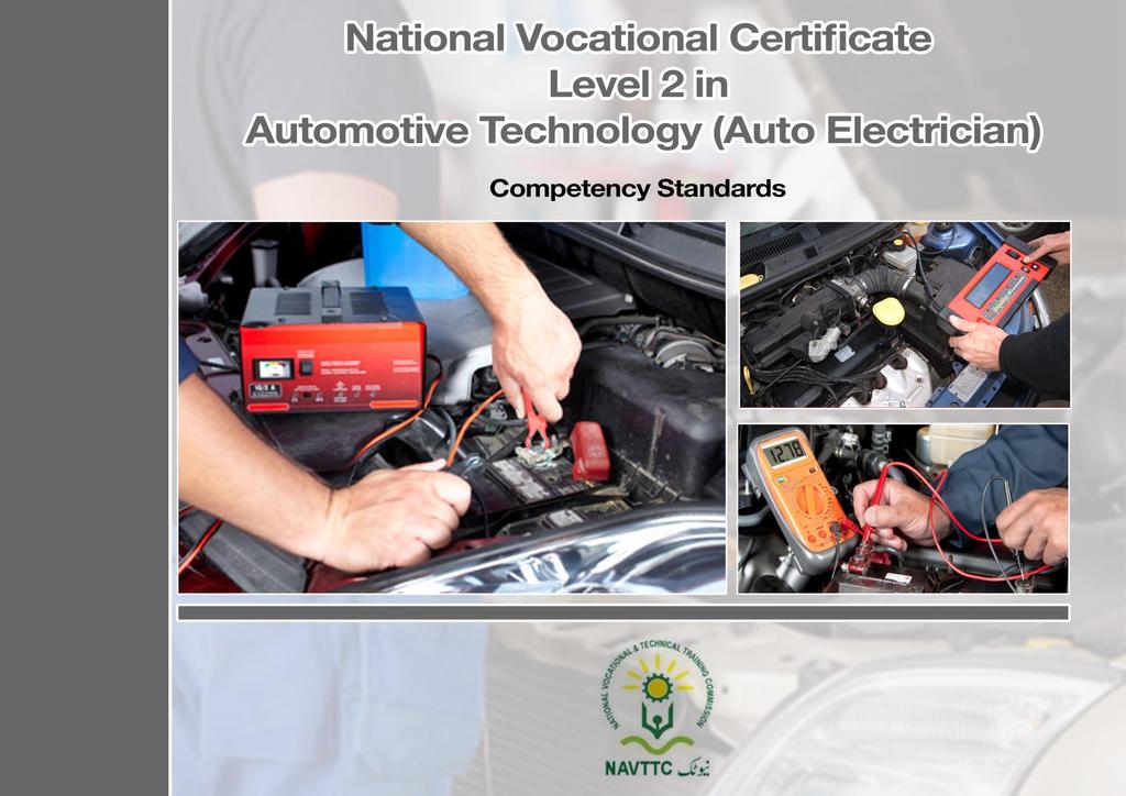
6 B:Repair Lighting System of Vehicle Overview: This Standard identifies the competencies required to repair lighting system of a vehicle by Auto Electrician in accordance with the organization s approved guidelines and procedures. Trainee will be expected to identify faults in different parts of the lighting system of a vehicle and fixing the problems by repairing or replacing the faulted parts. Trainee s underpinning knowledge regarding tools, techniques, methods and procedures for repairing/replacing auto-lighting parts will be sufficient to provide Trainee the basis for his/her work. Unit of B1: Diagnose Fault in Lighting System of the Vehicle. B2: Repair lighting system of the Vehicle. 5 P1. Carry out tests to determine faults using proper tooling and techniques. P2. Adopt a method for testing systems and components without causing damage to them. P3. Identify faults and determine repair actions to client. P4. Carry out tests according to guidelines and organization s procedures/policies. P5. Follow Repair manual for diagnosing fault in lighting system P1. Select tools and equipment according to job requirement. P2. Repair faults in the components as diagnosed according to procedures. P3. Adopt a method for repairing systems and components without causing damage to them P4. inspect and verify the fault is removed P5. Observe occupational health and safety precautions at all times. K1. Using multi-meter and test lamp. K2. Components and functions of lighting system. K3. Different types faults in lighting system of vehicles. K4. Techniques and procedures of diagnosing faults in lighting system. K5. Specific safety precautions and guidelines. K6. Reporting procedures of faults and possible repair actions. K7. Guidelines, procedures and policies of the organization. K8. Read and interpret repair manual. K1. Use of multi-meter, test lamp and toolkit K2. methods and procedures of repairing faults in the components ( harness, switch) K3.Techniques for inspecting and verifying the repair of lighting system. K4.Specific safety precautions and guidelines. K5. Guidelines, procedures and policies of the organization. K6. Read and interpret repair manual. Multi-meter, Test lamp Cutter Pliers, repair manuals Multi-meter, Test Lamp, Wire Insulating Tape, Cutter Pliers, screw drivers, spanners.
7 Unit of P6. Follow Repair manual for repairing lighting system of the vehicle B3: Replace Fuses/Connectors of Lighting System. P1. Select proper tools and equipment according to the job requirement P2. Follow the instructions of repair manual for the replacement of faulty fuses/connectors P3. Communicate to the client if the replacement of fuses/connectors is required P4. Follow Repair manual for replacement of fuses/connectors P5.Observe occupational health and safety precautions at all times. K1. Use of multi-meter, test lamp, fuse puller and cutter pliers K2. functions of fuses and connectors K3. classification of fuses (e.g. 10 Amp, 20 Amp, 30 Amp etc) K3. Read and interpret repair manual. K4. specific safety precautions and guidelines K5. Organizational standard operating procedures (SOPs) Multi-meter, Test Lamp, fuse puller, screw driver, cutter pliers, insulation tape B4: Repair Indicator Light Unit. B5: Replace Light Bulbs of the Vehicle. P1. Select tools and equipment according to job requirement. P2. Repair faults in the components as diagnosed according to procedures. P3. Adopt a method for repairing indicator light unit without causing damage to it. P4. inspect and verify the fault is removed P5. Observe occupational health and safety precautions at all times. P6. Follow Repair manual for repairing indicator light unit of the vehicle P1. Select proper tools and equipment according to the job requirement P2. Follow the instructions of repair manual for K1. Use of multi-meter, Flats & Phillips Screw Drivers, Test Lamp, Amery Paper, spanner K2. methods and procedures of repairing faults in indicator light unit K3. techniques for inspecting and verifying the repair of indicator light unit K4. Specific safety precautions and guidelines. K5. Guidelines, procedures and policies of the organization. K6. Read and interpret repair manual.. K1. Use of Phillips Type Screw Driver, Flat Type Screw Driver, spanner K2. Classification of bulbs (Volts and Watts) Multi-meter, Flats & Phillips Screw Drivers, Test Lamp, spanner, Amery Paper (for cleaning rusted points). Phillips Type Screw Driver, Flat Type Screw Driver, spanner 6
8 Unit of the replacement of faulted light bulbs P3. Communicate to the client if the replacement of light bulbs is required P4. Follow Repair manual for replacement of light bulbs P5. Observe occupational health and safety precautions at all times. K3. Read and interpret repair manual. K4. specific safety precautions and guidelines K5. Organizational standard operating procedures (SOPs). B6: Allign the Head Lights of the Vehicle. P1. Select proper tools and equipment according to the repair manual P2.adopt a method for adjusting head lights without causing damage to them P3. Inspect and verify the focus of head lights according to the repair manual P4. Observe occupational and machine safety at all times K1. Use of Phillips screw Driver, Head light Aligner ( Special Service Tools SST) K2. Read and interpret repair manual. K3. Techniques and procedure of using headlight aligner (SST) K4. specific safety precautions and guidelines K5. Organizational standard operating procedures (SOPs) Phillips screw Driver, Head light Aligner (SST), measuring tape 7
9 C:TestBattery Performance Overview: This Standard identifies the competencies required to test the battery performance of a vehicle by Auto Electrician in accordance with the organization s approved guidelines and procedures. Trainee will be expected to apply different tests including inspection of electrolyte and terminals, measuring the specific gravity, checking the level of distilled water and recharging the battery in order to enhance the performance of the battery of the vehicle.trainee sunderpinning knowledge regarding tools, techniques, methods and procedures for testing battery performance will be sufficient to provide Trainee the basis for his / her work. Unit of C1: Remove Battery from the Vehicle P1. Select proper tools and equipment according to the repair manual P2. Adopt a proper method for removing battery from the vehicle using repair manual P3. Disconnect terminals of the battery carefully. P4. Observe occupational health and safety precautions at all the times. K1. Use of Pliers and Ring Spanner K2. Read and interpret repair manual K3. Techniques for removing battery K4. Specific safety precautions and guidelines Pliers, Ring Spanner, and Silicon Gloves. C2:Inspect Electrolyte and Terminals of Battery P1. Select proper tools and equipment according to the repair manual P2. Adopt a proper method for inspecting battery electrolyte and terminals using repair manual P3. Report faults and possible solutions to client. P4. Observe occupational health and safety precautions at all the times. K1. Use of Hydro meter and Battery Tester K2. Read and interpret repair manual K3. Techniques for inspecting and verifying faults in the battery K4. Standard gravity of electrolytes K5. Specific safety precautions and guidelines K6. organizational reporting procedures Hydro meter, Battery Tester, Amery paper, Goggles and Silicon Gloves. 8
10 Unit of C3:Check the Specific Gravity of the electrolytes P1. Select proper tools and equipment according to the repair manual P2. Adopt a proper method for checking specific gravity of battery using repair manual P3. Observe occupational health and safety precautions at all the times. K1. Use of Hydrometer K2. Standard gravity of electrolytes K3. read and interpret repair manual K4. personal health and safety measures Hydrometer, Silicon Gloves. C4:Clean Terminals of the Battery P1.Select proper tools according to the repair manual P2. adopt a proper technique for cleaning terminals P3: Observe personal health and safety at all times K1. Use of contact Spray and Amery paper for cleaning K2. Read and interpret repair manual K3. Personal health and safety measures. Contact spray(wd40), Amery paper, spanner C5: Top up battery cells with distilled water P1. Adopt a proper method for topping up the battery cells with distilled water P2. carry out top up according to the repair manual s guidelines P3. Observe personal health and safety at all times K1. Use of hydrometer K2. Upper and lower levels of battery electrolytes. K3. Personal health and safety measures Hydro meter, Silicon Gloves C6: Recharge the Battery P1. Select proper tools and equipment according to the job requirement P2.select a proper method for recharging from the repair manual K1. Techniques and procedures to usebattery charger K2.Read and interpret repair manual K3. Personal and machine safety Battery charger, Multimeter, Silicon Gloves 9
11 Unit of P3. Observe personal health and safety at all times P4. set the amperes of tanger ( Battery Charger) according to battery specifications P5. connect battery terminals with the battery tanger/charger according to the procedure K4. procedures for setting the amperes of tanger K5. method of connecting battery terminals with the tanger C7: Test load of the battery P1. Select proper tools and methods for calculated load of the battery P2. Test battery performance through battery analyzer. P3. Measure battery charging with the help of multi-meter to analyze the volts. K1. Use of Battery analyzer and multi-meter K2.method of calculating Battery load. K3. Values of Charge, recharge and discharge. K4: Personal health and safety measures Battery Analyzer, multimeter, Silicon Gloves C8: Install Battery in the Vehicle P1. Wash Battery bracket and terminals to remove sulphur and rust P2. Re-assemble battery in bracket. P3. Install the positive (+) and negative (-) terminals and tight the lead. P4: follow repair manual s instructions for installation of battery P5. Start the car and check the performance. K1. Purpose of washing battery bracket and terminals K2: procedure of installation of battery K3: read and interpret repair manual Pliers, Ring spanner, Silicon Gloves. 10
12 D: Install and Repair Starting System of Vehicle Overview:This Standard identifies the competencies required toinstall and Repair Starting System of Vehicle byauto Electrician in accordance with the organization s approved guidelines and procedures. Trainee will be expected to identify starting system s common problems and to figure out possible solutions, either by repairing or replacing the parts of the starting system of the vehicle. Trainee sunderpinning knowledge regarding tools, techniques, methods and procedures for installation and repairing starting system of a vehicle will be sufficient to provide you the basis for his / her work. Unit of D1: Diagnose faults in Starting system of vehicle 11 P1. Carry out tests on following to determine faults: Glow Plug for diesel engine Spark Plug for petrol engine Ignition coil Injection pump solenoid valve for diesel engine Fuel pump and regulator valve Contact and Breaker Point (CB) and Condenser P2. Using proper tooling and techniques for performing diagnostic tests. P3. Adopt a method for diagnosing faults in starting system without causing damage to them. P4. Identify faults and determine repair actions to client. P5. Carry out tests according to guidelines and organization s procedures/policies. P6. Follow Repair manual for diagnosing fault in K1. Using multi-meter and test lamp. K2. Components and functions of lighting system. K3. Different types faults in lighting system of vehicles. K4. Techniques and procedures of diagnosing faults in lighting system. K5. Specific safety precautions and guidelines. K6. Reporting procedures of faults and possible repair actions. K7. Guidelines, procedures and policies of the organization. K8. Read and interpret repair manual. Multi-meter, scanner,tool kit (Spanner set, Screw driver, Pliers), Tester, Fuel pressure gauge.
13 Unit of starting system Check the cranking /self P7. Report the diagnose fault to the concerned department. D2: Repair Starter Motorof Vehicle D3: Install the starter motor in the Vehicle P1. Select tools and equipment according to job requirement. P2. Repair faults in the starter motor,as diagnosed, according to procedures. P3. Adopt a method for repairing starter motor without causing damage P4. inspect and verify the fault is removed P5. Observe occupational health and safety precautions at all times. P6. Follow Repair manual for repairing starter motor of the vehicle P1. Select relevant tools and methods for installation of starter motor in the vehicle. P2. Reconnect the wiring and connectors according to repair manual. P3. Tighten the bolts of starter motor to specified torque. P4. Ensure the fault is removed and starter motor is functioning properly. K1. use of toolkit and repair manual K2. procedure of repairing faults in starter motor K3. safety precautions for dismantling and assembling starter motor K4. method of measuring resistance of starter motor components. K1. Procedure for installation of starter motor in the vehicle. K2. Guidelines and procedures of repair manual of vehicles. K3. Importance of tightening the bolts at specified torque. K4. Method of connecting wires carefully. Screw driver and pliers Spanner Set, Socket SetRepair manual, soldering iron, Star Allen Key, Allan Key, Jumper Wire, Soldering wire, paste,multi-meter and Vernier caliper, Screw Drivers Set, Pliers Set, Test Lamp Screw driver and pliers Spanner Set, Socket Set Repair manual, soldering iron, Star Allen Key, Allan Key, Jumper Wire, Soldering wire, paste,multimeter and Vernier caliper, Screw Drivers Set, Pliers Set, Test Lamp 12
14 E: Install and Repair Charging System of Vehicle Overview:This Standard identifies the competencies required toinstall and Repair Charging System of Vehicle byauto Electrician in accordance with the organization s approved guidelines and procedures. Trainee will be expected toidentify chargingsystem s common problems and to figure out possible solutions, either by repairing or replacing the parts of the charging system of the vehicle. Trainee sunderpinning knowledge regarding tools, techniques, methods and procedures for installation and repairing charging system of a vehicle will be sufficient to provide Trainee the basis for his / her work. Unit of E1: Diagnose faults in Charging system of vehicle P1. Carry out tests on following to determine faults: Check battery warning light Alternator output voltage and ampere Check tension of belt P2. Use proper tooling and techniques to perform diagnostic tests. P3. Adopt a method for diagnosing faults in charging system without causing damage. P4. Identify faults and determine repair actions to relevant person. P5. Carry out tests according to guidelines and organization s procedures/policies. P6. Follow Repair manual for diagnosing fault in charging system P7. Report the diagnose fault to the concerned department. K1. Method of using multi-meter. K2. Components and functions of charging system of vehicle. K3. Different types faults in charging system of vehicles. K4. Techniques and procedures of diagnosing faults in charging system. K5. Specific safety precautions and guidelines. K6. Reporting procedures of faults and possible repair actions. K7. Guidelines, procedures and policies of the organization. K8. Read and interpret repair manual. Multi-meter, Scanner Tool kit,spanner set, Screw driver, Pliers,Tester. 13
15 Unit of E2. Replace Faulty Components of Alternator P1. Select relevant tools and method for the job. P2. Follow repair manual in replacing the faulty components of alternator. P3. Dismantle components of alternator according to repair manual. P4. Check resistance of Integrated Circuit (IC) with multi-meter. P5. Replace faulty components (bearings, stator, carbon brushes, rotor, rectifier, compotator, IC regulator, alternator shaft gear etc) according to procedure. P6. Assemble components of alternator according to repair manual. K1. Method of using tools and equipment for replacing components of alternator. K2. Procedure of dismantling and assembling the components of alternator. K3. Procedure and methods for replacing different components of alternator according to repair manual. K4. Method of checking resistance of IC with multi-meter. K5. Safety precautions and guidelines. Multi-meter, Vernier caliper, spanners, sockets. E3. Adjust Tension of Fan Belt P1. Select Special Service Tool (SST) for adjusting tension of fan belt. P2. Inspect fan belt to identify cracks and replace it. P3. Adopt method for adjusting tension of fan belt according to repair manual. P4. Observe safety precautions and guidelines at all times. P5. Check tension of fan belt using SST and verify the tension of belt with specifications mentioned in repair manual. K1. Functions and method of using special services tools. K2. Procedure of replacing fan belt safely. K3. Method and techniques for adjusting tension of fan belt. K4. Safety precautions and guidelines. K5. Procedure of checking tension of fan belt using SST. K6. Specifications for tension of fan belts according to repair manual. Special Services Tools (SST), Spanners, Socket Set, Hammer. 14
16 F : Repair Electrical Accessories of Vehicle Overview: This Standard identifies the competencies required to Repair Electrical Accessories of Vehicle by Auto Electrician in accordance with the organization s approved guidelines and procedures. Trainee will be expected toidentify faults in the electrical accessories of vehicle and figure out possible solutions, either by repairing or replacing the parts according to the requirement. Trainee s underpinning knowledge regarding tools, techniques, methods and procedures for installation and repairing/replacing electrical accessories of a vehicle will be sufficient to provide Trainee the basis for his / her work. Unit of F1: Diagnose faults in ElectricalAccessories of Vehicle P1. Carry out tests on following to determine faults: Power Windows Radio Antenna Cigarette Lighter Air Conditioner Fog Lights Defogger Centre Door Locking System Sun Roof Wiper Motor Horn Navigation/stereo System K1. Method of using multi-meter. K2. Components and functions of different electrical accessories in vehicle. K3. Types of faults in different electricalaccessories in vehicle. K4. Techniques and procedures of diagnosing faults in electrical accessories. K5. Safety precautions and guidelines. K6. Reporting procedures of faults and possible repair actions. K7. Guidelines, procedures and policies of the organization. K8. Read and interpret repair manual. Multi-meter, scanner, Tool kit (Spanner set, Screw driver, Pliers), Socket Set, Tester, Repair Manual. P2. Use proper tooling and techniques to perform diagnostic tests. P3. Adopt a method for diagnosing faults in electrical accessories without causing damage. 15
17 Unit of P4. Identify faults and determine repair actions to relevant person. P5. Carry out tests according to guidelines and organization s procedures / policies. P6. Follow Repair manual for diagnosing fault in accessories. P7. Report the diagnosed fault to the concerned department. F2. Repair or Replace Electrical Accessories in Vehicle P1. Select relevant tools and method for the job. P2. Follow repair manual in replacing or repairing the faulty electricalaccessories in vehicle. P3. Dismantle electrical accessories from vehicle according to manufacturer s manual. P4. Replace faulty electrical accessories(defogger, wiper motor, radio antenna, motor of sun-roof, horn etc) according to procedure. P5. Repair faulty electrical accessories (air conditioner, power window, cigarette lighter, center door locking system, navigation system etc.) according to procedure. P6. Check and verify the electrical accessory installed, after repairing or replacing, is functioning properly. K1. Read and interpret repair manual and manufacturer s instructions. K2. Procedure of dismantling and assembling of electrical accessories from vehicle. K3. Procedures for replacing accessories (defogger, wiper motor, radio antenna, motor of sun-roof, horn etc.). K4. Procedure for repairing of accessories (air conditioner, power window, cigarette lighter, center door locking system, navigation system etc.). K5. Safety precautions and guidelines. Multi-meter, scanner, Tool kit (Spanner set, Screw driver, Pliers), Socket Set, Tester, Repair Manual 16
18 List of tools, Equipment& Machinery Sr. No. Items 1. Ring spanner set 2. Philips Screwdrivers set 3. Test lamp 4. Head light alignment equipment 5. Hammer 6. Wire stripper 7. Soldering iron 8. Soldering lead 9. Flux 10. Multimeter 11. Cells tester 12. Hydrometer 13. Battery charger. 14. Battery cleaning kit 15. Thermometer, 16. Specific gravity chart 17. Dwell angle Meter 18. Spark plug cleaner Condenser tester Distributor tester 19. Spring tension checking meter 20. Bearing puller 21. Torque wrench 22. Tachometer 23. Armature glower 24. Mini hydraulic press machine. 25. Ammeter 26. Voltmeter 27. Filler gauge 28. Rectifier end 17
19 Frame 30. Puller 31. Vernier caliper 32. Repair Manual 33. Pliers 34. Socket Set 35. Scanner 38. Fuel pressure gauge 39. Paste 40. Battery Analyzer 41. Amery Paper 42. Head Light Aligner (SST) 43. Safety goggles 44. Safety Shoes 45. Safety Helmet 46. Silicon Gloves 47. Safety Covers 48. Fire Extinguisher 49. First Aid Box
20 19
Table of Contents. 4. Assessment Template List of Tools, Machinery & Equipment List of Consumable Supplies
 Page 1 Page 2 Table of Contents 1. Introduction... 4 2. Overview of the Program... 7 3. Curriculum Contents (Teaching and Learning Guide)... 11 Module 3.1: Apply saftey precautions & guidelines at workplace...
Unit AE01K Knowledge of Locating and Correcting Simple Electrical Faults in the Automotive Workplace
 Assessment Requirements Unit AE01K Knowledge of Locating and Correcting Simple Electrical Faults in the Automotive Workplace Content: Basic electrical principles a. Explain the direction of current flow
AUTO ELECTRICAL WORK
 1. PREAMBLE AUTO ELECTRICAL WORK This examination syllabus has been evolved from the Senior Secondary School Trade Curriculum. The examination syllabus does not replace the curriculum. The syllabus has
CHARGING SYSTEM PRECAUTION CH 1
 1NZ-FE ARGING ARGING SYSTEM ARGING SYSTEM PRECAUTION 1 1. Check that the battery cables are connected to the correct terminals. 2. Disconnect the battery cables when the battery is given a quick charge.
Curriculum. For. Auto-Service Mechanic
 Curriculum For Auto-Service Mechanic (6 Months) Code: VJ90S002 1 Scheme of Studies Auto Service Mechanic Sr Modules Theory Practical Total Hours # Hours Hours 1 Follow Safety Rules 13 30 43 2 Lubricating
2008 Toyota RAV ELECTRICAL Charging (2AZ-FE) - RAV4
 - RAV4") 2008 ELECTRICAL Charging (2AZ-FE) - RAV4 CHARGING SYSTEM PRECAUTION 1. Check that the battery cables are connected to the correct terminals. 2. Disconnect the battery cables if a quick charge is given
2008 ELECTRICAL Charging (2AZ-FE) - RAV4 CHARGING SYSTEM PRECAUTION 1. Check that the battery cables are connected to the correct terminals. 2. Disconnect the battery cables if a quick charge is given
2005 DVP Licensing Pty Ltd page 1
 C302 Perform battery state-of-charge test; determine C303 C587 C286 C287 Perform battery capacity test; confirm proper battery capacity for vehicle application; determine Perform battery capacity test(or
ACCREDITATION FACILITY AUDIT CHECKLIST
 ACCREDITATION FACILITY AUDIT CHECKLIST Institution Name: Date: Designated Trade: Marine and Outdoor Power Equipment Technician AC #: Contact: Location: Course Duration: of weeks: of hours total: of hours
CHARGING SYSTEM CHARGING SYSTEM CH 1
 CH1 CH2 Precautions PRECAUTIONS 1. Check that the battery cables are connected to the correct terminals. 2. Disconnect the battery cables when the battery is given a quick charge. 3. Do not perform tests
CHARGING SYSTEM. Page PRECAUTIONS... CH-2 TROUBLESHOOTING... CH-2 ON-VEHICLE INSPECTION... CH-2 ALTERNATOR... CH-6
 CHARGING SYSTEM Page PRECAUTIONS... CH-2 TROUBLESHOOTING... CH-2 ON-VEHICLE INSPECTION... CH-2 ALTERNATOR... CH-6 CH-2 CHARGING SYSTEM - Precautions, Troubleshooting,On-Vehicle Inspection PRECAUTIONS 1.
SECTION 1E ENGINE ELECTRICAL
 SECTION 1E ENGINE ELECTRICAL CAUTION: Disconnect the negative battery cable before removing or installing any electrical unit or when a tool or equipment could easily come in contact with exposed electrical
Competency Standards. For. Automotive Technician
 National Vocational and Technical Training Commission (NAVTTC) Competency Standards For Automotive Technician 1 Table of Contents S. No Content Page No. 1 Structural information 23 2 Competency Map. 4
STARTING & CHARGING SYSTEM SECTIONSC CONTENTS IDX
 STARTING & CHARGING SYSTEM SECTIONSC GI MA EM LC EC CONTENTS FE PRECAUTIONS...2 Supplemental Restraint System (SRS) AIR BAG and SEAT BELT PRE-TENSIONER...2 Wiring Diagrams and Trouble Diagnosis...2 BATTERY...3
STARTING & CHARGING SYSTEM
 K ELECTRICAL SECTION SC A STARTING & CHARGING SYSTEM B C D CONTENTS E PRECAUTIONS... 2 Precautions for Supplemental Restraint System (SRS) AIR BAG and SEAT BELT PRE-TEN- SIONER... 2 Precautions for Power
Automotive Electrical Systems
 Automotive Electrical Systems 1 Electrical Circuits Contain 4 main parts 1. Power source battery alternator 2. Load 3. Control 4. Path 2 3 Batteries What is a Battery? An electrochemical device which stores
030 AUTOMOBILE ELECTRICAL WORKS
 EXAMINATION STRUCTURE The trade consists of the following related courses: 191 Metal Work 193 Building/Engineering Drawing. 194 Basic Electricity 030 AUTOMOBILE ELECTRICAL WORKS The trade shall also be
STARTING SYSTEM (1ZZ FE) (April, 2003)
 (April, 2003)") STARTING & CHARGING STARTING SYSTEM (1ZZ FE) (April, 2003) STARTING SYSTEM (1ZZ FE) (April, 2003) INSPECTION 19 1 190QO 02 1. INSPECT STARTER ASSY NOTICE: These tests must be performed within 3 to 5 seconds
STARTING & CHARGING STARTING SYSTEM (1ZZ FE) (April, 2003) STARTING SYSTEM (1ZZ FE) (April, 2003) INSPECTION 19 1 190QO 02 1. INSPECT STARTER ASSY NOTICE: These tests must be performed within 3 to 5 seconds
ELECTRICAL BATTERY/STARTING/CHARGING SYSTEMS DIAGNOSTICS
 Z ELECTRICAL 8A - 1 ELECTRICAL GROUP INDEX page AUDIO SYSTEMS... 8F BATTERY/STARTER/GENERATOR SERVICE... 8B BATTERY/STARTING/CHARGING SYSTEMS DIAGNOSTICS... 8A CHIME WARNING/REMINDER SYSTEM... 8U HORNS...
Page 1 of 1 ALTERNATORS. Overview. Intek TM V-Twin Cylinder OHV Engine Service Manual Version 1.0. Copyright 1999 by Briggs and Stratton Corporation
 Overview Alternator Identification Page 1 of 3 The alternator systems installed on Briggs & Stratton Intek V-Twin Cylinder OHV Engines can easily be identified by the color of the stator output wires and
Battery Operation. Battery Construction. Battery State Of Charge. Battery Load Test. Battery Rating Systems 2/14/12
 Battery Operation Batteries, Charging and Donald Jones Brookhaven College Batteries convert chemical energy into electrical energy During discharge the battery s plate composition is changed During charging
Table No. 1 provides a means of identifying the various alternator systems. Note: All output figures are rated at 3600 RPM. TABLE NO.
 The alternator systems installed on Briggs & Stratton Intek OHV-Twin Cylinder Engines can easily be identified by the color of the stator output wires and the connector. Table No. 1 provides a means of
CHARGING SYSTEM PRECAUTION CH 1
 1GR-FE ARGING ARGING SYSTEM ARGING SYSTEM PRECAUTION 1 1. PRECAUTION (a) Check that the battery cables are connected to the correct terminals. (b) Disconnect the battery cables if the battery is charged
CHARGING SYSTEM ON-VEHICLE INSPECTION
 CHARGING (2UZFE) CHARGING SYSTEM CHARGING SYSTEM ONVEHICLE INSPECTION CH1 CH0J603 CAUTION: Check that the battery cables are connected to the correct terminals. Disconnect the battery cables when the battery
AUTOMOTIVE TECHNOLOGY Electricity and Electronics
 AUTOMOTIVE TECHNOLOGY Electricity and Electronics Al Santini Retired, College of DuPage Glen Ellyn, Illinois Jack Erjavec, Series Editor Professor Emeritus, Columbus State Community College Columbus, Ohio
ALTERNATOR - BOSCH 35/75-AMP & 40/90-AMP
 ALTERNATOR - BOSCH 35/75-AMP & 40/90-AMP 1988 Chrysler LeBaron Convert/Coupe 1988 ALTERNATORS & REGULATORS Chrysler Motors - Bosch 35/75 & 40/90 Amp Alternator All Models DESCRIPTION The charging system
THE ALT AL ERNA RN T A OR
 THE ALTERNATOR Initial Voltage of the Battery (Engine Not Running) Charging Voltage for the Battery (Engine Running) Testing for Maximum Output of the Alternator Inspecting the Regulator Positive Side
Engine Electrical System
 Engine Electrical System 3 Foreword This manual has been prepared by experts and specialists of,engineering Department of Saipa Yadak Company to be used as a guide by the repairers of electrical systems.we
1. SPECIFICATION Typ. HPS EPS Capacity 120 A 140 A. 76/140 A at 1,800/6,500 rpm. 70/120 A at 1,800/6,500 rpm. Normal output.
 145300 093 1. SPECIFICATION Typ. HPS EPS Capacity 120 A 140 A Alternator Battery Normal output 70/120 A at 1,800/6,500 rpm 76/140 A at 1,800/6,500 rpm Regulator voltage 14.6 V Brush Length 12.5 mm Wear
Lab Specifications. Automotive 2 Wheeler Repair
 Lab Specifications Automotive 2 Wheeler Repair An initiative of Ministry of Skill Development & Entrepreneurship, Govt. of India and National Skill Development Corporation 02 If we have to promote the
1. SPECIFICATION
 000000 093 1. SPECIFICATION Specification HPS EPS Alternator Crankshaft pulley : Alternator Pulley 1 : 2.94 Normal output (idling/2200 rpm) 70/120 A 70/140A Regulator voltage 14.6 V Brush Length 12.5 mm
IMPORTANT SAFETY INSTRUCTIONS
 ASSOCIATED Model 6039 Battery Tester Operator's Manual IMPORTANT SAFETY INSTRUCTIONS 1. SAVE THESE INSTRUCTIONS This manual contains important safety and operating instructions for the battery tester you
STARTING/CHARGING SYSTEMS Brought to you by Eris Studios NOT FOR RESALE
 STARTING/CHARGING SYSTEMS General Description 1. General Description A: SPECIFICATION Vehicle model Starter Generator Item Specification Type Reduction type Model 428000-5760 Manufacturer DENSO Voltage
Lab Specifications. Automotive 4 Wheeler Repair
 Lab Specifications Automotive 4 Wheeler Repair An initiative of Ministry of Skill Development & Entrepreneurship, Govt. of India and National Skill Development Corporation 02 If we have to promote the
Motor Cycle Mechanic 1
 Motor Cycle Mechanic 1 Training Objective: Motor Cycle is a popular use in urban as well as rural areas throughout the country. This course aims at producing semi skilled workers who can carryout minor
IMILV01 Carry out routine light vehicle maintenance
 IMILV01 Carry out routine light vehicle maintenance Overview This NOS is about conducting routine maintenance, adjustment and replacement activities as part of the periodic servicing of light vehicles.
ALTERNATOR - CHRYSLER 40/90-AMP & 50/120 AMP
 ALTERNATOR - CHRYSLER 40/90-AMP & 50/120 AMP 1988 Chrysler LeBaron Convert/Coupe 1988 ELECTRICAL Chrysler Motors 40/90 & 50/120 Amp Alternators FWD Models DESCRIPTION The charging system consists of an
BATTERY 8A - 1 BATTERY CONTENTS
 TJ BATTERY 8A - 1 BATTERY CONTENTS page DESCRIPTION AND OPERATION BATTERY... 1 DIAGNOSIS AND TESTING BATTERY... 3 SERVICE PROCEDURES BATTERY CHARGING... 13 DESCRIPTION AND OPERATION BATTERY DESCRIPTION
REMOVAL OF ALTERNATOR
 CH6 CHARGING SYSTEM ALTERNATOR REMOVAL OF ALTERNATOR 1. DISCONNECT CABLE FROM NEGATIVE TERMINAL OF BATTERY CAUTION: Work must be started after approx. 20 seconds or longer from the time the ignition switch
ALTERNATOR - HITACHI
 ALTERNATOR - HITACHI 1986 Isuzu Trooper II 1986 Alternators & Regulators HITACHI ALTERNATORS Isuzu DESCRIPTION Hitachi alternators are conventional 3-phase, self-rectifying alternators. Three positive
SERVICE INFORMATION BATTERY/CHARGING SYSTEM XL CHARGING SYSTEM INSPECTION 15-5 REGULATOR/RECTIFIER 15-6 ALTERNATOR 15-7
 15. BATTERY/CHARGING SYSTEM SERVICE INFORMATION 15-1 TROUBLESHOOTING 15-2 BATTERY 15-3 CHARGING SYSTEM INSPECTION 15-5 REGULATOR/RECTIFIER 15-6 ALTERNATOR 15-7 SERVICE INFORMATION GENERAL t The battery
Course Information Course Number: AMT 1003 Course Name: Automotive Foundations
 Course Information Course Number: AMT 1003 Course Name: Automotive Foundations Credit-By-Assessment (CBA) Competency List Written Assessment Competency List Electrical Describe the effects of temperature,
AT2403 VEHICLE MAINTENANCE
 AT2403 VEHICLE MAINTENANCE UNIT I MAINTENANCE OF RECORDS AND SCHEDULES 1. Why daily maintenance is required for a vehicle? (Nov 2012) 2. State the importance of Job card. (Nov 2012) 3. What are the safety
AUTOMOTIVE SERVICE INTRODUCTION (505)
") DESCRIPTION This is an entry-level course in Automotive Service. Through demonstrations, lectures, research and practical experiences is designed to introduce the student to abroad experience in the use
DESCRIPTION This is an entry-level course in Automotive Service. Through demonstrations, lectures, research and practical experiences is designed to introduce the student to abroad experience in the use
SECTION 6 4 SERVICE PROCEDURES AND SPECIFICATIONS. Electrical components
 SERVICE PROCEDURES AND SPECIFICATIONS Electrical components SECTION 6 4 Specifications........................................... 206 Checking battery condition................................ 210 Battery
SECTION 6 4 SERVICE PROCEDURES AND SPECIFICATIONS. Electrical components
 SERVICE PROCEDURES AND SPECIFICATIONS Electrical components SECTION 6 4 Specifications........................................... 190 Checking battery condition and fluid level................... 194 Battery
STARTING SYSTEMS 8B - 1 STARTING SYSTEMS CONTENTS
 TJ STARTING SYSTEMS 8B - 1 STARTING SYSTEMS CONTENTS page DESCRIPTION AND OPERATION STARTER MOTOR... 2 STARTER RELAY... 3 STARTING SYSTEM... 1 DIAGNOSIS AND TESTING STARTER MOTOR... 8 STARTER MOTOR NOISE
AER Introduction to Automotive Services
 2013 NATEF JOB TASKS COMPLETION REQUIREMENT: P1-95% P2-80% P3-50% Student Name: DETAILED COURSE CONTENT LIGHT VEHICLE MAINTENANCE AND INSPECTION TASK LIST Version 1.0 1) PREPARATION AND DOCUMENTATION SHOP
Problems with your 12V Booster?
 Problems with your 12V Booster? Check this Trouble Shooting Manual for your answer 1. Tools Required 2. First Tests to conduct 2.1 Measure the Voltage at the Clamps 2.2 Testing the power (Amps) 3. Testing
A/C Generator Systems
 A/C Generator Systems What is the function of the charging system? Provide power for all electrical loads Recharge the starting battery What happens if the charging systems puts out too much power? Voltage
SECTION 6 4 SERVICE PROCEDURES AND SPECIFICATIONS. Electrical components
 SERVICE PROCEDURES AND SPECIFICATIONS Electrical components SECTION 6 4 Specifications........................................... 214 Checking battery condition and fluid level................... 218 Battery
BATTERY 8A - 1 BATTERY CONTENTS
 ZJ BATTERY 8A - 1 BATTERY CONTENTS page GENERAL INFORMATION INTRODUCTION... 1 OVERVIEW... 1 DESCRIPTION AND OPERATION BATTERY MOUNTING... 3 BATTERY SIZE AND RATINGS... 2 BATTERY... 2 DIAGNOSIS AND TESTING
16. CHARGING SYSTEM 16-0 CHARGING SYSTEM NEXXON 50
 16 16 CHARGING SYSTEM SERVICE INFORMATION------------------------------------------------ 16-2 TROUBLESHOOTING----------------------------------------------------- 16-3 BATTERY --------------------------------------------------------------------
jegs.com
 Contents Wiring Harness w/ Fuse Panel Installation Instructions Turn Signal Plug w/ Terminals 2 Headlight Plugs 3/4 Grommet 10 ¼ Terminals 4 Ring Terminals 10 Wire Ties Fusible Link 2 Screws & Nuts 2 Plastic
CHAPTER 10 ELECTRIC SYSTEM
 CHAPTER 10 ELECTRIC SYSTEM 1. ELECTRIC SYSTEM ELECTRIC SYSTEM 1.1 WIRING DIAGRAM CK20-USA 196WA00A S196-WOO Jul. 2003 10-3 CK20(M) CHAPTER 10 CK20-EU 196WA51A 10-4 S196-WOO Jul. 2003 ELECTRIC SYSTEM 1.2
ON-VEHICLE INSPECTION
 CH2 P11586 CHARGING CHARGING SYSTEM ONVEHICLE INSPECTION 1. CHECK BATTERY ELECTROLYTE LEVEL Check the electrolyte quantity of each cell. MaintenanceFree Battery: CH03L01 If under the lower level, replace
ALTERNATOR PRECAUTIONS. Some precautions should be taken when working on this, or any other, AC charging system.
 The alternator charging system is a negative (-) ground system which consists of an alternator, a regulator, a charge indicator, a storage battery and wiring connecting the components, and fuse link wire.
Problems with your 12/24V Booster?
 Problems with your 12/24V Booster? Check this Trouble Shooting Manual for your answer 1. Tools Required 2. First Tests to conduct 2.1 Measure the Voltage at the Clamps 2.2 Testing the power (Amps) 3. Testing
STARTER CIRCUIT TROUBLESHOOTING
 2000 Honda Accord EX Sedan V6-3.0L Vehicle > Starting and Charging > Starting System > Starter Motor > Testing and Inspection > Component Tests and General Diagnostics STARTER CIRCUIT TROUBLESHOOTING Starter
Inspecting and Cleaning the Battery Cables and Connections
 JOB SHEET 42 Inspecting and Cleaning the Battery Cables and Connections Name: -------------------------- Station: --------------------- Date: NATEF Correlation This Job Sheet addresses the following NATEF
ARTICLE BEGINNING SERVICE PRECAUTIONS
 Page 1 of 96 ARTICLE BEGINNING SERVICE PRECAUTIONS WARNING: WARNING: CAUTION: When performing any inspection or service procedure on this vehicle, ensure following service precautions are followed to prevent
Practical Workbook. Vehicle Systems Maintenance. Assessment Recording Forms Level SCQF Level 4
 Practical Workbook Vehicle Systems Maintenance Assessment Recording Forms 3902-11 Level 1 3902-74 SCQF Level 4 3902 - Level 1/SCQF Level 4 Candidate s unit tracking assessment and verification page Candidate
1984 Jeep CJ7. IGNITION SYSTEM - SOLID STATE' 'Distributors & Ignition Systems MOTORCRAFT SOLID STATE IGNITION (SSI)
") TESTING SECONDARY CIRCUIT CHECK CAUTION: When checking secondary voltage, do not remove spark plug wires from spark plugs No. 3 on 4-cylinder, No. 1 or 5 on 6-cylinder and No. 3 or 4 on V8 Engines. 1.
TESTING SECONDARY CIRCUIT CHECK CAUTION: When checking secondary voltage, do not remove spark plug wires from spark plugs No. 3 on 4-cylinder, No. 1 or 5 on 6-cylinder and No. 3 or 4 on V8 Engines. 1.
Diesel Technology: Electrical and Electronic Systems
 Diesel Technology: Electrical and Electronic Systems NATEF Crosswalk The following NATEF Electrical/Electronic Systems tasks (rev. 2001) are covered in this publication. The chart shows where each task
STARTING & CHARGING SYSTEM
 K ELECTRICAL SECTION SC A STARTING & CHARGING SYSTEM B C D CONTENTS E PRECAUTIONS... 2 Precautions for Supplemental Restraint System (SRS) AIR BAG and SEAT BELT PRE-TEN- SIONER... 2 Precautions for Power
SECTION M. ELECTRICAL. Section Description Page No.
 SECTION M. ELECTRICAL. Section Description Page No. M.1 General Page 2 M.2 Alternator Page 2 M.3 Battery Page 7 M.4 Hazard Warning System Page 7 M.5 Brake Fail Warning System Page 8 M.6 Seat Belt Warning
PHILIPS TECHNICAL LIBRARY ELECTRICITY IN CARS R. H. BACON. Second Edition
 PHILIPS TECHNICAL LIBRARY ELECTRICITY IN CARS R. H. BACON Second Edition M N. V. Philips' Gloeilampenfabrieken, Eindhoven, 1967, 1975, 1976 A II rights reserved. No part of this publication may be reproduced
SEMPEO SQA Unit Code H Carrying out routine servicing of mechanical equipment
 Carrying out routine servicing of mechanical equipment Overview This standard covers a range of basic mechanical equipment servicing/scheduled maintenance competences, that will prepare you for entry into
GROUP CONTENTS CHARGING SYSTEM IGNITION SYSTEM SPECIAL TOOL GENERAL DESCRIPTION
 16-1 GROUP 16 CONTENTS CHARGING SYSTEM 16-3 GENERAL DESCRIPTION 16-3 SPECIAL TOOL 16-4 CHARGING SYSTEM DIAGNOSIS 16-4 ON-VEHICLE SERVICE 16-6 GENERATOR OUTPUT LINE VOLTAGE DROP TEST 16-6 OUTPUT CURRENT
1NZ-FE ENGINE CONTROL SYSTEM
 PREPARATION 1NZ-FE ENGINE CONTROL SYSTEM 1NZ-FE ENGINE CONTROL SYSTEM PREPARATION SST 1 09817-33190 Sensor Socket Wrench 2 PREPARATION 1NZ-FE ENGINE CONTROL SYSTEM RECOMMENDED TOOLS 09082-00040 TOYOTA
COURSE DESIGN COURSE TITLE : AUTOMOTIVE SERVICING NC I
 COURSE DESIGN COURSE TITLE : AUTOMOTIVE SERVICING NC I NOMINAL DURATION : 1200 HOURS QUALIFICATION LEVEL : NC I COURSE DESCRIPTION : This course is designed to enhance the knowledge, skills, and attitudes
Simplified Check Program for Charging Systems
 SB-3 Battery Load Tester Instruction Manual Simplified Check Program for Charging Systems The SB-3 is a variable load battery tester that provides a simplified check for the alternator and starter. CONGRATULATIONS
DESCRIPTION & OPERATION
 DESCRIPTION & OPERATION 1999-2000 STARTING & CHARGING SYSTEMS Generators & Regulators NOTE: This article also applies to Lexus LX470. For Lexus LX470, refer to Land Cruiser, unless otherwise indicated.
STARTING & CHARGING SYSTEM
 K ELECTRICAL SECTION SC A STARTING & CHARGING SYSTEM B C D CONTENTS E PRECAUTIONS... 2 Precautions for Supplemental Restraint System (SRS) AIR BAG and SEAT BELT PRE-TEN- SIONER... 2 Wiring Diagrams and
Deep Cycle Battery Safety. First. Battery Handling, Maintenance & Test Procedures
 Deep Cycle Battery Safety. First. Battery Handling, Maintenance & Test Procedures Crown deep cycle batteries employ a low-maintenance design. They do require periodic maintenance and effective charging
Battery. Student booklet
 Battery Student booklet Battery - INDEX - 2006-04-07-12:51 Battery Batteries are all over the place, in our cars, our PCs, laptops, portable MP3 players and cell phones. A battery is essentially a can
OPERATION & MAINTENANCE INSTRUCTIONS
 AUTOMATIC BATTERY CHARGER / MAINTAINER MODEL NO: CBO9-12 PART NO: 6267025 OPERATION & MAINTENANCE INSTRUCTIONS ORIGINAL INSTRUCTIONS LS0118 - ISS 3 INTRODUCTION Thank you for purchasing this CLARKE product.
ELECTRIC VEHICLE DISMANTLING MANUAL
 RAV4 EV Electric Vehicle ELECTRIC VEHICLE DISMANTLING MANUAL QEA38 Series Foreword This guide was developed to educate and assist dismantlers in the safe handling of Toyota RAV4 EV electric vehicles. RAV4
Minuteman International s Trouble Shooting the Kawasaki 17 HP Engine Engine Will Not Start.
 Minuteman International s Trouble Shooting the Kawasaki 17 HP Engine Instructions: Follow these steps until the problem is resolved Engine Will Not Start. (Battery is good and engine is cranking) 1. Do
2000 F-150 Workshop Manual
 Page 1 of 14 SECTION 303-06: Starting System 2000 F-150 Workshop Manual DIAGNOSIS AND TESTING Procedure revision date: 06/17/1999 Starting System Refer to Wiring Diagrams Cell 20, Starting System for schematic
STARTING & CHARGING SYSTEM
 K ELECTRICAL A SECTION STARTING & CHARGING SYSTEM B C D CONTENTS E PRECAUTIONS... 2 Precautions for Supplemental Restraint System (SRS) AIR BAG and SEAT BELT PRE-TEN- SIONER... 2 Wiring Diagrams and Trouble
Automotive Parts. Charging & Starting Systems
 Automotive Parts Charging & Starting Systems Charging Systems Output voltage kept to about 2 volts higher than battery voltage Controlled by varying current into rotor field winding (voltage regulator
ELECTRICAL SYSTEM CONTENTS ELECTRICAL PARTS 5-1 IGNITION/CHARGING SYSTEM 5-2 IGNITION COIL 5-2 STATOR COILS 5-3 REGULATOR/RECTIFIER 5-3
 ELECTRICAL SYSTEM CONTENTS ELECTRICAL PARTS 5-1 IGNITION/CHARGING SYSTEM 5-2 IGNITION COIL 5-2 STATOR COILS 5-3 REGULATOR/RECTIFIER 5-3 STARTER SYSTEM 5-4 STARTER MOTOR INSPECTION 5-5 STARTER RELAY INSPECTION
Diesel Technology: Electrical and Electronic Systems
 Diesel Technology: Electrical and Electronic Systems Instructional/Task Analysis 2. Composition of atoms Unit 1: Introduction to Diesel Electrical and Electronic Systems 3. Electrical charges in atoms
OPERATION & MAINTENANCE INSTRUCTIONS
 AUTOMATIC BATTERY CHARGER / MAINTAINER MODEL NO: CBO9-12 PART NO: 6267025 OPERATION & MAINTENANCE INSTRUCTIONS LS0315 INTRODUCTION Thank you for purchasing this CLARKE product. Before attempting to use
OWNER S MANUAL PORTABLE POWER COMPACT & ROBUST
 52731 18 AMP-HOUR 12 VOLT OVERHEAT PROTECTION JUMP START OWNER S MANUAL PORTABLE POWER COMPACT & ROBUST 18 Amp-Hour, 12 Volt Wall charger 6-gauge booster cable Built in ultra-bright LED work light Safety
Diagnose and rectify faults in a motorcycle electronic ignition system
 Page 1 of 5 Diagnose and rectify faults in a motorcycle electronic ignition system Level 4 Credits 4 Purpose This unit standard is for people in the motorcycle and automotive electrical repair industries.
System Description. Diagnostic Aids. Enhanced Ignition System Diagnosis
 Enhanced Ignition System Diagnosis System Description This system includes the distributor, the CAM position sensor ignition coil with the ignition coil driver, the secondary wires, spark plugs, the knock
STARTING & CHARGING SYSTEM
 K ELECTRICAL A SECTION STARTING & CHARGING SYSTEM B C D CONTENTS E PRECAUTIONS... 2 Precautions for Supplemental Restraint System (SRS) AIR BAG and SEAT BELT PRE-TEN- SIONER... 2 Precautions for Power
2003 Explorer/Mountaineer Workshop Manual
 Page 1 of 11 SECTION 414-00: Battery and Charging System 2003 Explorer/Mountaineer Workshop Manual DIAGNOSIS AND TESTING Procedure revision date: 06/18/2002 Charging System Printable View (257 KB) Refer
Chapter 5 Part A: Starting and charging systems
 Chapter 5 Part A: Starting and charging systems Contents Alternator drivebelt - removal, refitting and tensioning............6 Alternator -.............................7 Alternator - testing and overhaul.............................8
ENGINE DISPLACEMENT 2000 NUMBER OF VALVES 16 ENGINE SET NUMBER
 MANUFACTURER Subaru TYPE Forester ENGINE DISPLACEMENT 2000 NUMBER OF VALVES 16 ENGINE CODE / NUMBER FA20 DIT VEHICLE CATEGORIES M TRANSMISSION AT VERSION Direct LiquiMax-2.1 PETROL ECU MANUFACTURER / CODE
ELECTRICAL SYSTEM CONTENTS ELECTRICAL PARTS 5-1 IGNITION/CHARGING SYSTEM 5-2 IGNITION COIL 5-2 STATOR COILS 5-3 REGULATOR/RECTIFIER 5-4
 ELECTRICAL SYSTEM CONTENTS ELECTRICAL PARTS 5-1 IGNITION/CHARGING SYSTEM 5-2 IGNITION COIL 5-2 STATOR COILS 5-3 5 REGULATOR/RECTIFIER 5-4 STARTER SYSTEM 5-4 STARTING MOTOR INSPECTION 5-5 STARTER RELAY
TECHNICIAN SAFETY INFORMATION
 2009 Honda Accord L4-2.4L Vehicle > Restraints and Safety Systems > Air Bag Systems > Service Precautions TECHNICIAN SAFETY INFORMATION SRS Precautions and Procedures General Precautions NOTE: Some systems
FACILITY ACCREDITATION CHECKLIST R: 04/27/06 APPRENTICESHIP Designated Trade: Motor Vehicle Mechanic Level (circle one)
") FACILITY ACCREDITATION CHECKLIST R: 04/27/06 APPRENTICESHIP Designated Trade: Level 1 2 3 (circle one) Institution: Evaluator(s) / / Rating Code: Y = Yes* N = No* R = Required * * Please use a CHECKMARK
FACILITY ACCREDITATION CHECKLIST R: 04/27/06 APPRENTICESHIP Designated Trade: Level 1 2 3 (circle one) Institution: Evaluator(s) / / Rating Code: Y = Yes* N = No* R = Required * * Please use a CHECKMARK
OPERATION & MAINTENANCE INSTRUCTIONS
 AUTOMATIC BATTERY CHARGER / MAINTAINER MODEL NO: CBO9-6/12 PART NO: 6267020 OPERATION & MAINTENANCE INSTRUCTIONS LS0615 INTRODUCTION Thank you for purchasing this CLARKE product. Before attempting to use
C802/C802D/C802TD/C820 Alternators Troubleshooting Guide
 C802/C802D/C802TD/C820 Alternators Troubleshooting Guide Hazard Definitions These terms are used to bring attention to presence of hazards of various risk levels or to important information concerning
NATEF Task List A6: ELECTRICAL/ELECTRONIC SYSTEMS
 NATEF Task List A6: ELECTRICAL/ELECTRONIC SYSTEMS For every task in Electrical/Electronic Systems, the following safety requirement must be strictly enforced: Comply with personal and environmental safety
SCION tc SECURITY (V5) Preparation
 Preparation") Preparation Part Number: PT398-21070 Kit Contents Item # Quantity Reqd. Description 1 1 2 1 GBS ECU Hardware Bag Contents Item # Quantity Reqd. Description 1 1 V5 Security ECU 2 1 ECU Mounting Bracket
Preparation Part Number: PT398-21070 Kit Contents Item # Quantity Reqd. Description 1 1 2 1 GBS ECU Hardware Bag Contents Item # Quantity Reqd. Description 1 1 V5 Security ECU 2 1 ECU Mounting Bracket
MODEL 6010A 6 12 VOLT BATTERY CHARGER ASSOCIATE
 MODEL 600A 6 VOLT BATTERY CHARGER ASSOCIATE IMPORTANT SAFETY INSTRUCTIONS. SAVE THESE INSTRUCTIONS. This manual contains important safety and operating instructions for the battery charger you have purchased.
SECTION 6 4 SERVICE PROCEDURES AND SPECIFICATIONS. Electrical components
 SERVICE PROCEDURES AND SPECIFICATIONS Electrical components SECTION 6 4 Specifications........................................... 194 Checking battery condition and fluid level................... 198 Battery