Power Factor Correction Equipment
|
|
|
- Martha Leonard
- 5 years ago
- Views:
Transcription

1 Power Factor Correction Equipment
2
3 Content KNK Power Capacitors for Low Voltage GENERAL 4 KNK Cylindrical Aluminium Housing 6 KNK Cylindrical Aluminium Housing (delta connection) 8 KNK Cylindrical Aluminium Housing 9 KNK Cylindrical Aluminium Housing (delta connection) 11 KNK Cylindrical Aluminium Housing 12 KNK Cylindrical Aluminium Housing (delta connection) 13 KNK Three-phase Capacitors KNK9103, KNK Prismatic 15 KLV High Voltage Power Capacitors GENERAL 19 KLV 1xx1, KLV3xx1, KLV3xx0 - Single-phase 20 KLV 1xx3, KLV3xx3 - Three-phase 21 KLV 1xx4, KLV3xx4 - Single-phase with Two Outputs (Twin) 22 KLS Induction Heating Capacitors GENERAL 23 KLS x0xx, KLSx1xx - Air Cooled 24 KLS x2xx, KLSx3xx, KLSx4xx - Water Cooled 25 Capacitor Duty Contactors KC12, KC16, KC20, KC25, KC33, KC40, KC60 29 Power Factor Control Relay PFCmax 6, PFCmax PFC-CX 32 3
4 KNK Power Capacitors for Low Voltage KNK5015, KNK5065, KNK1053, KNK2053, KNK9053, KNK9101, KNK9103, KNK9141, KNK9143 Applications The KNK capacitors are used for power factor correction of inductive consumers (transformers, electric motors, rectifi in industrial networks for voltages of up to 660 V. Design Cylindrical aluminium housing with metallized three-layer polypropylene film dielectric, especially treated for better contact. the capacitors are: impregnated with polymerized a vegetable oil which is PCB-free and biologically degradable, DRY type - patented Self-Healing Capacity Damage may occur on the dielectric due to fatigue which results in local breakdowns on certain points. the resultant electric current devaporises the thin metallized layer and isolates the damaged spot from the rest of the capacitor. Capacitance loss is almost negligible (some pf) during this process. this self-healing property guarantees operating reliability and long life expectancy of the capacitor. Self-healing of KNK capacitors 1. metallized layer 2. polypropylene film 3. breakdown point 4. devaporised metallized layer
5 KNK Power Capacitors for Low Voltage KNK5015, KNK5065, KNK1053, KNK2053, KNK9053, KNK9101, KNK9103, KNK9141, KNK9143 Discharge Resistor Every capacitor incorporates a resistor which serves for capacitor discharging after network disconnection to 75 V in 3 minutes. Over-Pressure Disconnector Every capacitor incorporates a mechanical over-pressure disconnector which disconnects the capacitor in case of overloading or other internal damages. Routine Testing of Capacitors Capacitors are subjected to the following tests during the production process: - sealing test (70 C, 6 hrs) - voltage tests between layers with AC voltage equal to 2.15 Un, 2 s - voltage test between layers and the housing with AC voltage 3600 V, 2 s - measurement of loss angle tanδ at a rated voltage, frequency of 100 Hz, and room temperature - measurement of capacitance at a rated voltage, frequency of 100 Hz, and room temperature Available Versions of KNK Capacitors Indoor mounting: KNK single-phase in cylindrical housing KNK three-phase in cylindrical housing KNK three-phase in cylindrical housing - DRY type KNK three-phase in cylindrical housing - DRY type KNK three-phase in cylindrical housing KNK single-phase in a prism shaped housing KNK three-phase in a prism shaped housing KNK single-phase with cap in a prism shaped housing (IP 55) KNK three-phase with cap in a prism shaped housing (IP 55) 5
6 KNK Power Capacitors for Low Voltage KNK5015, KNK5065, KNK1053, KNK2053, KNK9053, KNK9101, KNK9103, KNK9141, KNK9143 Technical data Type KNK5015 KNK5065 KNK1053 KNK2053 KNK9053 KNK9101 KNK9103 KNK9141 KNK9143 Standards IEC Publ /2 Rated voltage U n V see table Rated frequency f Hz 50 or 60 Max. allowable operating voltage Max. allowable operating current 1.1 x Un (8 h per day) 1.5 x In (including combined effects of overvoltages, harmonics and capacitance tolerance) 1.3 x In (effects of overvoltages, harmonics and capacitance tolerance) only for KNK2053 In-rush current (max.) 150 x 200 x 100 x 150 x 200 x Protection degree IP00 IP20 IP00 IP55 Losses dielectric 0.2 W/ total max kvar Capacitance tolerance -5 % to +10 % Temperature class/ temperature limits Permitted ambient temperature C -25/D -25 to +55 other on request Permitted storage temperature Discharge time Safety Dielectric C -40 to min. to 75 V or less by discharge resistors, other on request self-healing, overpressure disconnector metallized polypropylene film Filling Sealed with plant oil; PCB-free Dry sealed with plant oil; (PCB-free) Test conditions Expected life time between layers 2.15 x Un AC 2 s ; layers-housing 3.6 kv AC 2 s > hours class D > hours class C Notes: On request, capacitors with other power and voltage ratings, shapes, and connections are available. - all rights reserved for any possible changes. - In-rush current must be limited to maximal permitted value. Ordering: - capacitor type - capacitor power - rated voltage - rated frequency - quantity and delivery terms Ordering example for three-phase 25 kvar capacitor of 400 V: KNK1053, 25 kvar, 400 V, 50 Hz. 6


7 Single-phase Capacitors KNK cylindrical aluminium housing V, kvar f n = 50 Hz Resin filled Un (V) f n = 60 Hz Qn Cn (μf) In H (kg) Packing unit (pcs) Un (V) Qn Cn (μf) In H (kg) Resin filled Packing unit (pcs)
 Rated current H (kg) Packing unit (pcs) 2.5 3 x 16.6 3.6 145 0.45 36 3 3 x 19.9 4.3 145 0.45 36 4 3 x 26.5 5.")
 Rated current (μf) H (kg) Packing unit (pcs) 2.")
8 Three-phase Capacitors KNK cylindrical aluminium housing, delta connection V, kvar Rated voltage 400 V, f n = 50 Hz Resin filled Rated power Rated capacitance (μf) Rated current H (kg) Packing unit (pcs) x x x x x Rated voltage 440 V, 50 Hz Rated power Rated capacitance (μf) Rated current H (kg) Packing unit (pcs) x x x x Rated voltage 480 V, 50 Hz Rated power Rated capacitance (μf) Rated current (μf) H (kg) Packing unit (pcs) Rated voltage 525 V, 50 Hz Rated power Rated capacitance (μf) Rated current H (kg) Packing unit (pcs) x x x x x
9 Three-phase Capacitors KNK cylindrical aluminium housing V, kvar f n = 50 Hz - Delta Connection Dry C n (μf) Qn U n = 400 V U n = 400 V U n = 380 V U n = 440 V Un = 440 V U n = 420 V U n = 400 V U n = 480 V Un = 480 V U n = 440 V U n = 400 V U n = 525 V Un = 525 V U n = 460 V U n = 440 V H FI (kg) Packing unit (pcs) 9
10 Three-phase Capacitors KNK cylindrical aluminium housing V, kvar C n (μf) U n = 690 V Qn H FI (kg) Packing unit (pcs) f n = 60 Hz Dry C n (μf) U n = 400 V U n = 400 V U n = 380 V U n = 440 V U n = 440 V U n = 420 V U n = 400 V U n = 480 V U n = 480 V U n = 440 V U n = 400 V U n = 525 V U n = 525 V U n = 460 V U n = 440 V H FI (kg) Packing unit (pcs) 10
11 Three-phase Capacitors KNK Cylindrical Aluminium Housing, Delta Connection V, kvar f n = 50 Hz Dry C n (μf) U n = 400 V U n = 400 V U n = 380 V U n = 440 V U n = 440 V U n = 420 V U n = 400 V U n = 480 V U n = 480 V U n = 440 V U n = 400 V U n = 480 V U n = 480 V U n = 440 V U n = 400 V H FI (kg) Packing unit (pcs) 11


12 Three-phase Capacitors KNK Cylindrical Aluminium Housing V, kvar f n = 50 Hz Resin filled C n (μf) U n = 400 V U n = 400 V U n = 380 V U n = 440 V U n = 440 V U n = 420 V U n = 400 V U n = 480 V U n = 440 V U n = 400 V U n = 525V U n = 525 V U n = 460 V U n = 400 V U n = 690 V H FI (kg) Packing unit (pcs) 12
13 Three-phase Capacitors KNK Cylindrical Aluminium Housing, DELTA CONNECTION V, kvar f n = 60 Hz Resin filled C n (μf) U n = 400 V Un = 400 V Un = 380 V Un = 440 V Un = 440 V Un = 420 V Un = 400 V Un = 480 V Un = 440 V Un = 400 V Un = 525 V Un = 525 V Un = 460 V Un = 440 V Un = 690 V H FI (kg) Packing unit (pcs) 13

")
14 Three-phase Capacitors KNK9103, KNK Prismatic V, kvar KNK9103 KNK9143 The cap for KNK9103 (type KNK9153) 14
15 Three-phase Capacitors KNK9103, KNK Prismatic V, kvar f n = 50 Hz Resin filled U n (V) C n (μf) A A B D KNK9103 (kg) KNK9143 (kg) x M x M x M x M x M x M x M x M x M x M x M x M x M x M x M x M x M x M x M x M x M x M x M x M x M x M x M x M x M x M x M x M x M x M x M x M x M x M x M x M x M x M x M x M x M x M x M x M x M x M x M x M x M
16 Three-phase Capacitors KNK9103, KNK Prismatic V, kvar f n = 60 Hz Resin filled U n (V) C n (μf) A A B D KNK9103 (kg) KNK9143 (kg) x M x M x M x M x M x M x M x M x M x M x M x M x M x M x M x M x M x M x M x M x M x M x M x M x M x M x M x M x M x M x M x M x M


17 Three-phase Capacitors KNK9101, KNK Prismatic V, 5 60 kvar KNK9101 KNK9141 The cap for KNK9101 (type KNK9151) 17
18 Three-phase Capacitors KNK9101, KNK Prismatic V, 5 60 kvar f n = 50 Hz Resin filled U n (V) C n (μf) A A B D KNK9101 (kg) KNK9141 (kg) M M M M M M M M M M M M M M M M M M M M M M M M M M M M M M M M M M M M M M M M M M M M M M M M M M

. Capacitors are supplied in sets of three to provide an economical unbalance detection scheme.")
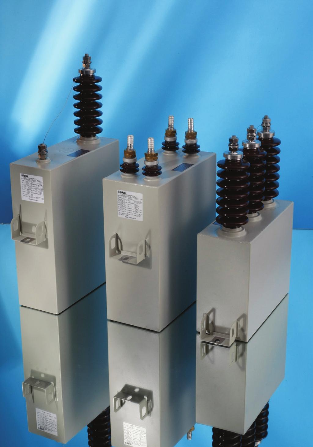
19 High Voltage Power Capacitors Single phase Capacitors Three-phase capacitors Single phase with two outputs - twin capacitors General Advanced technology of KLV capacitors is based on construction of all-film capacitor sections, folding foil edge design, improved electrical and mechanical connections between sections and impregnation with environmentally compatible insulating oil. KLV capacitors have very low dielectric losses and are designed for long service life. KLV 3xxx Internally fused capacitors. Each capacitor element has a separate internal fuse. KLV1xxx Capacitors without internal fuses KLVxxx4 Single phase capacitors with two outputs (twin). Capacitors are supplied in sets of three to provide an economical unbalance detection scheme. This is particularly advantageous in low output capacitor banks. Technical data Rated power (max.) 600 kvar, 50 Hz 720 kvar, 60 Hz Rated voltage 1,0-20 kv Rated frequency 50 or 60 Hz Losses Total losses lower than 0,15 W/kvar Dielectric losses 0,07 W/kvar Dielectric All-film (hazy polypropylene) Impregnating fluid Environmentally compatible impregnating oil based on M/DBT (NON - PCB) Discharge resistor Built in discharge resistor reduces the voltage on a de-energised capacitor from the crest of rated voltage to 75V in 10 minutes or less (discharge to 50V in 5 minutes on demand). Permissible overloads Maximum permissible current 1,3 x In continuously Maximum permissible voltage 1,1 x Un continuously, 12h per day Routine tests Sealing test Voltage test between terminals 2,15 x rated voltage AC, 10 s or 4,3 x rated voltage DC, 10 s AC voltage test between terminals and container According to IEC , Table 3, 10 s Discharge resistor test Measurement of losses (tan δ) Service conditions Temperature categories up to -40 /D Upper temperature category limit C D Maximum Highest mean over 24 h Highest mean over 1 year Low temperature limit during oparation Installation Outdoor or indoor -25 C or -40 C Installation altitude (above sea level) 1000 m standard, up to 4000m on demand Case material: Stainless steel plate 1,5 mm thick Finish / Colour Two-component durable painting RAL 7032 (light grey) on treated surfaces. Fixing Depending on the height of capacitor, container is equiped with one or two mounting brackets on the narower sides. Brackets have mounting slots 11 x 20 mm. Terminals and connections Bushings Brown or gray porcelain bushings, welded to the container. Thread of terminal stud M14 Current 110A max. Connections Terminal clamps with provision to accommodate any combination of 2 conductors from 4 mm 2 solid to 50 mm 2 stranded wire are available on demand. The capacitor unit grounding is provided by unpainted surface of mounting brackets. Pressure switch with terminal cap Supplied on demand. Nameplate Durable plastic label with permanent printing Quality Iskra MIS is certified according to ISO 9001(quality) and ISO (environment) Standards IEC ANSI / IEEE 18 NEMA CP 1 19
20 High Voltage Power Capacitors KLV 1xx1 (1xx0) and 3xx1 (3xx0), single-phase capacitors, typical dimensions at 50 Hz U n KLV 1xxx (without internal fuses) U n KLV 3xxx (internally fused) Dimensions (kv) (kv) A B B* C BIL kv BIL 125 kv (kg) (kg) 100 2,00-16,5 (20) 2,00-2, R ,00-16,5 (20) 2,00-4, R ,00-16,5 (20) 2,00-4, R ,27-16,5 (20) 2,27-7, R ,72-16,5 (20) 2,72-7, R ,18-16,5 (20) 3,18-9, R ,64-16,5 (20) 3,64-9, R ,1-16,5 (20) 4, R ,56-16,5 (20) 4,56-14, R ,00-16,5 (20) 5,00-14, R ,46-16,5 (20) 5,46-14, R D * Notes: * Dimensions with an asterisk (*) refer to internally fused capacitors 1) Voltage in parenthesis ( ) refer to one-bushing capacitors only 2) For output and voltage outside this range, please contact factory 3) Case sizes are typical and actual sizes will be confirmed at the time of order 4) Capacitor container could have 2 or 4 brackets (1 or 2 brackets on narrower side) Dimension C - 2R means 1 bracket from each side (capacitor type KLVxx1x); 4R means 2 brackets on each side, one on the top and one on the bottom, except where the height is 310mm or below, where brackets are on the bottom only (type KLVxx2x). 5) Dim A may expand up to 115% due to thermal flexure 6) Power at 60Hz = 1,2 x power at 50Hz Picture 1: Two - bushing capacitor KLVxxx1 (insulated container) Picture 2: Single - bushing capacitor KLVxxx0 (voltage on the container) WHUPLQDOFODPSV PPPP RQGHPDQG 0 ' % & [ $ While every care has been taken to ensure that the information contained in this document is correct, no responsibility can be accepted for any inaccuracy. We reserve the right to alter or modify the information contained herein at any time in the light of technical or other developments. Technical specifications are valid under normal operating conditions only. We do not accept any responsibility for any misuse of the product and cannot be held liable for indirect or consequential damages. Technical data and design can be subject to change and should be confirmed prior to ordering. 20
21 High Voltage Power Capacitors KLV 1xx3 and 3xx3, three-phase capacitors, BIL 20/60 kv, typical dimensions (Picture 3) U n Dimensions at 50 Hz A B B* D E (kv) (kg) (kg) 3,3-7, KLV 1xx3 and 3xx3, three-phase capacitors, BIL 28/75 kv, typical dimensions (Picture 4) * U n Dimensions at 50 Hz A B B* D E (kv) (kg) (kg) up to Notes: * Dimensions with an asterisk (*) refer to internally fused capacitors 1) For output and voltage outside this range, please contact factory 2) Case sizes are typical and actual sizes will be confirmed at the time of order 3) Pressure switch on demand 4) Either 2 or 4 fixing brackets are used, depending on the height of the unit. Special bracket positions can be provided if required. Please specify at the enquiry stage. 5) Dim A may expand up to 115% due to thermal flexure 6) Power at 60Hz = 1,2 x power at 50Hz Three - Phase capacitors Picture 3 Picture 4 * While every care has been taken to ensure that the information contained in this document is correct, no responsibility can be accepted for any inaccuracy. We reserve the right to alter or modify the information contained herein at any time in the light of technical or other developments. Technical specifications are valid under normal operating conditions only. We do not accept any responsibility for any misuse of the product and cannot be held liable for indirect or consequential damages. Technical data and design can be subject to change and should be confirmed prior to ordering. 21
 135 200 220 250 240 22 23 100 (2x50) 135 310 340 250 240 28 29 150 (2x75) 135 400 430 250 240 35 37 2,0-4,16 200 (2x100) 135 520 560 250 240 42 44 250 (2x125) 135 640 680 250 240 49 51 300")
 (kg) (kg) 50 (2x25) 135 200 220 300 510 22 23 100 (2x50) 135 310 340 300 510 28 29 150 (2x75) 135 400 430 300 510 35 37 up to 6,93 200 (2x100) 135 520 560 300")
22 High Voltage Power Capacitors KLV 1xx4 and 3xx4, single-phase capacitors with two outputs (twin), BIL 20/60 kv, typical dimensions (Picture 5) U n Dimensions at 50 Hz A B B* D E * (kv) (kg) (kg) 50 (2x25) (2x50) (2x75) ,0-4, (2x100) (2x125) (2x150) (2x200) KLV 1xx4 and 3xx4, single-phase capacitors with two outputs (twin), BIL 28/75 kv, typical dimensions (Picture 6) U n Dimensions at 50 Hz A B B* D E * (kv) (kg) (kg) 50 (2x25) (2x50) (2x75) up to 6, (2x100) (2x125) (2x150) (2x200) Picture 5 Picture 6 Connection Notes: * Dimensions with an asterisk (*) refer to internally fused capacitors 1) For output and voltage outside this range, please contact factory 2) Case sizes are typical and actual sizes will be confirmed at the time of order 3) Either 2 or 4 fixing brackets are used, depending on the height of the unit. Special bracket positions can be provided if required. Please specify at the enquiry stage. 4) Dim A may expand up to 115% due to thermal flexure 5) Power at 60Hz = 1,2 x power at 50Hz While every care has been taken to ensure that the information contained in this document is correct, no responsibility can be accepted for any inaccuracy. We reserve the right to alter or modify the information contained herein at any time in the light of technical or other developments. Technical specifications are valid under normal operating conditions only. We do not accept any responsibility for any misuse of the product and cannot be held liable for indirect or consequential damages. Technical data and design can be subject to change and should be confirmed prior to ordering. 22
.Applications Applications KLS capacitors are especially designed for inductive heat generating plants operating at frequencies between 50 and 10000 Hz.")

23 Induction Heating Capacitors KLS Advanced technology of low loss KLS capacitor units is based on construction of ALL-FILM capacitor sections and impregnation with environmentally compatible insulating oil (NON-PCB).Applications Applications KLS capacitors are especially designed for inductive heat generating plants operating at frequencies between 50 and Hz. Manufactured by request, these capacitors are designed to comply with the specific requirements of each customer. Most of these capacitors provide for step changes in kvar by virtue of terminated sections within each unit. This allows for the tuning of the circuit for changing inductive loads. Construction KLS capacitors utilize a polypropylene film and aluminum foil construction with NON-PCB liquid impregnant. The impregnating fluid M/DBT and textured polypropylene film have exceptional dielectric properties over the entire operating temperature range of induction heating capacitors. The extended foil design of capacitor elements makes nearly continuous connection to the foils, so capacitor overcurrent and cooling capabilities are increased. KLS capacitors designed for operating at lower frequencies are air cooled. Medium frequency capacitors utilize internal tubes for cooling. Bushings and connection for cooling water are placed on capacitor case cover. Safety Requirements The standard capacitor does not have internal discharge devices - all capacitor units should be connected directly with a discharge device, this may be other electrical equipment connected directly across the capacitor (i.e. furnace coil). The discharge path must not have a disconnecting switch or fuses. When the capacitors is switched off and re-energized at short intervals, arrangements should be made so that, at the time of re-application of the voltage, the capacitor terminal voltage shall not be more than 10% of the rated voltage of the capacitor. Before working on a capacitor ensure that the capacitor bank is properly isolated, wait to ensure the capacitor is discharged and short circuit the capacitor terminals before handling. Quality Assurances All capacitors are subjected to the following routine tests: Sealing test on container short circuit discharge test 1.7 rated voltage DC, one discharge, for internally fused capacitors Capacitance measurements Loss measurements at 50 Hz Voltage test between terminals at 2.0 rated voltage AC, 10 sec or 4.0 rated voltage DC, 10 sec. Voltage test terminals to container where applicable Capacitors comply with IEC and VDE 0560 Part 9. 23
24 Induction Heating Capacitors KLS x0xx, KLS x1xx, air-cooled 50 / 60 Hz TECHNICAL DATA Voltage range U n V Output range kvar up to 600 Rated frequency f n Hz 50 / 60 Tolerance of capacity -5% % (narrower tolerances on request) Losses (typical) W/kvar Temperature category (ambient temperature) C -25 / +45% (air-cooled capacitors) Impregnating fluid Discharge resistors Internal fuses Temperature monitoring Pressure monitoring Case material Biodegradable NON-PCB dielectric oil based on M/DBT On demand Built in, without fuses on demand Temperature sensors can be built-in upon request Pressure switches can be built-in upon request Mild steel or stainless steel Case finish One layer of top coat on one layer of primer. Standard colour RAL Dimensions Dim A : mm, dim B : up to 1000 mm Actual sizes will be confirmed at the time of order. KLS x0xx, KLS x1xx - AIR COOLED CAPACITORS 50/60 Hz Picture 1 - KLS x12x Air Cooled Capacitors 50/60 Hz 0 0XSWR$ 0$$ % $ [ 24
 Losses (typical) W/kvar 0.2-0.")

25 Induction Heating Capacitors KLS x2xx, x3xx, x4xx, water cooled Hz TECHNICAL DATA Voltage range U n V Output range (fn > 60 Hz) kvar up to 3000 Rated frequency f n Hz Tolerance of capacity -10% % (narrower tolerances on request) Losses (typical) W/kvar Temperature category (ambient temperature) C +1 / +45% (water cooled capacitors) Outlet water temperature C 45 max Max. pressure of incoming cooling water bar 8 Cooling water flow l/min Impregnating fluid Biodegradable NON-PCB dielectric oil based on M/DBT Discharge resistors NO Internal fuses NO Temperature monitoring Temperature sensors can be built-in upon request Pressure monitoring Pressure switches can be built-in upon request Case material Brass or aluminium containers for medium frequency capacitors Case finish One layer of top coat on one layer of primer. Standard colour RAL Dimensions Dim A : mm, dim B : up to 1000 mm Actual sizes will be confirmed at the time of order. Number of taps up to 8 25
26 Induction Heating Capacitors KLS x2xx, x3xx, x4xx, water cooled Hz Picture 2 - KLS x3xx Single Cooling Coil Capacitor (Insulated Poles, Dead Case) &RROLQJFRLO 0XSWR$ 0$ 0; Picture 3 - KLS x2xx Single Cooling Coil Capacitor ( Live Case)Hz :DWHUFRQQHFWLRQ $ & % & % FRPPRQ WHUPLQDO &RPPRQWHUPLQDOVZLWK UHPRYDEOHFRSSHUEXV ZLWK0EROW [ $ $ ; SUHVVXUHVZLWFKRU WKHUPRVWDWRQGHPDQG &20021 Picture 4 - KLS x400 Double Cooling Coils Capacitor - dead Picture 5 -KLS x200 Double Cooling Coils Capacitor - live case 26
27 Induction Heating Capacitors KLS Type designation data: K DIELECTRIC APPLICATION INTERNAL DEVICES CONSTRUCTION CONTAINER NUMBER OF TERMINALS, CONNNECTION A1 K capacitor A2 L dielectric polypropylene (all-film) A3 S induction heating capacitor 1 discharge resistors built in 2 without discharge resistors 3 internal fuses and discharge resistors built in A4 4 internal fuses built in 5 discharge resistors and thermostat or pressure switch built-in 6 thermostat or pressure switch built-in 7 internal fuses, discharge resistors and thermostat or pressure switch built-in 8 internal fuses, and thermostat or pressure switch built-in 0 air cooled, common terminal on the case (»live case«) 1 air cooled, isolated terminals A5 2 water cooled, common terminal on the case (»live case«) 3 water cooled, isolated terminals 4 water cooled, two cooling coils, isolated terminals A6 0 case side mounting 2 case bottom mounting A7 0 number of terminals 27
28 Induction Heating Capacitors KLS Ordering data: When ordering, please state: Rated output Rated voltage Rated frequency Tolerance of capacitance -...% / +...% Cooling Terminal connection Number of bushings Internal fuses Discharge resistors Thermostat Pressure switch Special conditions Standards and regulations kvar V Hz air / water one terminal connected to the case ( live ) / isolated ( dead ) While every care is taken to ensure that the information contained in this publication is correct, no legal responsibility can be accepted for any inaccuracy. The Company reserves the right to alter or modify the information contained herein at any time in the light of technical or other developments. Yes/No Yes/No Yes/No Yes/No 28

 Power dissipation per pole Mechanical life 50 or 60 Hz 50 / 60 Hz Electrical life 240 V 480 V 600 V W")
29 Capacitor Duty Contactors KC12, KC16, KC20, KC25, KC33, KC40, KC60 USE Switching of capacitors in systems for compensation of reactive energy (classic automation devices). Features: Conforms to utilization category AC-6b Saves costs of expensive replacement Long electrical life Reduces watt losses during ON condition, saves energy High safety No risk of dangerous voltage Switching of capacitor bank in parallel without de-rating Less maintenance and downtime Approvals: CSA TECHNICAL DATA Type Rating at 50/60 Hz < 55 C * kvar V V Current at 230 V Current carrying capacity kvar Current at 400 V kvar / current rating as per UL (kvar/a) Power dissipation per pole Mechanical life 50 or 60 Hz 50 / 60 Hz Electrical life 240 V 480 V 600 V W million operations KC / / / KC / / / KC / / / KC / / / KC / / / KC / / / KC / / / Note: * Average ambient temperature should not exceed 45 C within the 24-hour period in KC12 to KC25; clip-on mounting on 35 mm wide rail acc. with IEC and IEC KC33 to KC60; clip-on mounting on 75 mm wide rail 29
30 Capacitor Duty Contactors KC12, KC16, KC20, KC25, KC33, KC40, KC60 TECHNICAL DATA Type Rating at 50/60 Hz < 55 C Time lag between make contacts of Aux. block and contactor Upper block Wire details Coil consumption Holding time of main contacts of Aux. block Lugs - at Crosssectional area Lenght Material contactor end Lugs at Aux. block end Tightening torque 50 Hz 60 Hz 50 / 60 Hz ms ms mm 2 mm Nmm 2 VA VA VA KC PTFE coated Resistance wire Ring type lug Pin type lug KC KC KC KC KC KC Dimension: KC12, KC16, KC20, KC25 KC33, KC40, KC60 KC20/KC25 KC12 KC16 KC12 c=117 KC16 c=122 KC20 c=130 KC25 c=135 KC12, KC16 KC20, KC25 KC12, KC16 KC20, KC25 KC60 KC33 KC40 KC33 KC40 KC60 KC12 KC16 KC20 KC25 KC33 KC40 KC60 Ordering data: The type designation and control voltage are stated when ordering the contactors. KC /60 Frequency Control voltage Version of contacts Type 30

31 Power Factor Control Relay PFCmax 6 & PFCmax 12 USE Power factor regulators PFCmax6 (6 steps) and PFCmax12 (12 steps) measure cos ϕ of a supply system and control the automatic connection and disconnection of compensation capacitors according to desired cos ϕ. Features: FCP (Fast Computerized Program) System minimizing the number of capacitor connections and disconnections 6 and 12 relay regulators according to the type Connected step display, a digital display for cos ϕ and differentiation of a sign for reactive power L (inductive) and C (capacitive) Three-digit LCD with seven segments Setting of parameters without the need for disconnecting the regulator power supply Option to configure the regulator even when it is still in the process of regulating the capacitors Option for using 50 or 60 Hz frequencies All measurements displayed on one single display Easy to mount with no need for tools Programming from keypad on the front: (3 keys) Size 144 x 144 mm according to DIN Measurement and power supply in one single input Connection Diagrams: PFC MAX6 PFC MAX9 Dimension: 31

32 Power Factor Control Relay PFC-CX USE Power factor control relay PFC-CX measure cos ϕ of a supply system and control the automatic connection and disconnection of compensation capacitors according to desired cos ϕ. Microprocessor controlled power factor controller with 1-phase measurement system. Features: Start menu for easy commissioning Automatic detection and correction of the phase of current and voltage connection Fully-automatic c/k-value setting, self adapting, connection of different capacitor step sizes possible Automatic detection and usage of the optimum capacitor step Switching programs: Best Fit, LIFO, manual mode, combifilter, progressive Capable for 4-quadrant operation 1-phase measurement system also suitable for non-sinusodial currents and voltages Supply voltage taken from measuring voltage Voltage measuring V, Hz Current measuring 15 ma - 5 A, suitable for CT x/1 A und x/5 A Connection with plugable screw terminals LCD with backlit Display of all important grid and system parameters Display of THD U and voltage harmonics from 3rd to 15th order Input for temperature sensor or thermostate (n/o) (this input can be used to switch-over the tarif by n/o contact) Alarm relay with voltfree n/o contact (operated at normal function) TTL-interface on rear Instrument casing for cutout 144 x 144 mm, depth 49 mm Protection class IP20 (casing), IP50 (front) 32
33 Power Factor Control Relay PFC-CX Connection Diagrams: Dimension: 33
34 34 Notes
35
36 Ljubljanska c. 24a, SI Kranj, Slovenia Tel.: , Fax: info@iskra-mis.si, Published by Iskra MIS, d. d. Version 1.0, April 2012 design Nimbus d.o.o.
Three Phase Capacitors KNK
 Three Phase Capacitors KNK Features Connection profile Φ 90 and 116 mm 2-16 mm 2, Φ 136 mm 2-25 mm 2 *Use of flexible conductors only with ferrules Capacitors equipped with discharge resistors Rated power
Trifazni kondenzatorji KNK
 Trifazni kondenzatorji KNK Features Vezava profile Φ 90 and 116 mm 2-16 mm 2, Φ 136 mm 2-25 mm 2 *Use of flexible conductors only with ferrules Capacitors equipped with discharge resistors Nazivna moč
1 Low-voltage Power-factor Correction capacitors KNK APPLICATION DESIGN
 APPLICATION The KNK capacitors are used for power - factor correction of inductive consumers (transformers, electric motors, rectifiers) in industrial networks for voltages of up to 660 V. DESIGN Cylindrical
Low Voltage Power Factor Corrections
 Low Voltage Power Factor Corrections Capacitors Contents General information on Iskra Capacitors Type Page Introduction 4 1. Single-phase capacitor type KNK5015 230 550 V, 1,67.5 kvar 2. Three-phase capacitors
LV Capacitor Bank APC
 LV Capacitor Bank APC The ABB comprehensive solution for automatic power factor correction: APC standard, reinforced and de-tuned automatic capacitor banks The ABB comprehensive solution for automatic
PhiCap Capacitors for Power Factor Correction
 PhiCap Capacitors for Power Factor Correction Product Profile 2000 http://www.epcos.com PhiCap AC Capacitors for Power Factor Correction General The PhiCap series, is a well approved and reliable EPCOS
EMPAC Metal enclosed capacitor bank for wind applications
 EMPAC Metal enclosed capacitor bank for wind applications Introduction The EMPAC is a Metal Enclosed Capacitor Bank suitable for voltages between 1 kv and 36 kv for reactive compensation in MV networks
LV Capacitor CLMD Reliability for Power Factor Correction
 LV Capacitor CLMD Reliability for Power Factor Correction Reliability for power factor correction CLMD construction The CLMD capacitor consists of a number of wound elements made with a dielectric of metallized
CP Automatic capacitor bank
 CP 254 - Automatic capacitor bank STE-CP254_V2_général.doc Page 1 CP 254 - General presentation CP 254 is a range of MV capacitor banks designed to be used in electrical networks up to 36kV. The capacitor
POWER CAPACITORS. Cylindrical capacitor standard duty
 Construction Dielectric: Polypropylene film Non PCB, Soft Polyurethane resin Extruded round aluminium can with stud Provided with discharge resistors Overpressure disconnector Features Three phase, delta
High Reliable Components for Power Factor Correction and Power Quality
 High Reliable Components for Power Factor Correction and Power Quality It's all about saving your money! Contents Power Factor Correction Capacitors Page 3 Basic Harmonic Filter Reactors Page 11 Standard
LV Capacitor Bank APC
 LV Capacitor Bank APC The ABB comprehensive solution for automatic power factor correction: APC standard, reinforced and de-tuned automatic capacitor banks The ABB comprehensive solution for automatic
Technical brochure. The Vector series The ABB comprehensive solution for automatic power factor correction
 Technical brochure The Vector series The ABB comprehensive solution for automatic power factor correction 2 Applications The Vector series The Vector series The Vector series is a powerful and compact
PhaseCap Premium PFC Capacitors Gas-impregnated n Dry type n Concentric winding n Wavy cut n Triple safety system
 Premium PFC Capacitors General capacitors in cylindrical aluminum cases have been designed for power factor correction in low-voltage plant. Loads like motors and transformers consume active power as well
LV Capacitors QCap-L series Capacitors for power factor correction
 LV Capacitors QCap-L series Capacitors for power factor correction ABB and power quality ABB is a leader in power and automation technologies that enable utility and industry customers to improve their
Visual comparison of Plain & Hazy PP Film
 ECOVAR High Voltage Power Capacitors are manufactured at our Sinnar Plant in India which is an ISO 9001 accredited facility & houses a computer aided design manufacturing processing and testing infrastructure
C1000 Series Automatic Cap Bank
 C1000 Series Automatic Cap Bank Metal Enclosed - Medium Voltage Capacitors Assemblies Fixed / Auto Medium Voltage 5, 15, 25 and 35 kv Class Customized to your specifications The Reactive Power Solution
multicond Power capacitors Data sheet: multicond
 Power capacitors multicond Monitoring Optimizing Recording multicond are one-phase and three-phase power capacitors for reactive current compensation, developed for networks with many harmonics. Apart
High Reliable Components for Power Factor Correction and Power Quality
 High Reliable Components for Power Factor Correction and Power Quality It's all about saving your money! Power Factor Correction Capacitors Type LKT Features that matter: Overcurrent up to 2.2 times rated
Automatic COSYS PFC. Automatic power factor correction system NEW
 Automatic COSYS PFC Automatic power factor correction system NEW cosys_178_a_1_x_cat cosys_178_a_1_x_cat appli_xxx_a  Function Your reactive energy consumption vary depending on the type and using conditions
Power Factor Correction
 Power Factor Correction It's all about saving your money! Features that matter n Overcurrent up to 2.2 times rated current n Inrush current up to 300 times rated current n Self-healing type, segmented
Technical Specification For Outdoor Substation Harmonic Filter Banks
 Technical Specification For Outdoor Substation Harmonic Filter Banks One of Three 5th, 11th & 23rd, 34.5 kv, Rated Harmonic Filter Assemblies Provided for a Central Venezuela Heavy Oil Production Field
NEW. Heavy Duty Capacitors. Power Factor Correction Capacitors Type LKT. It s all about saving your money! Features that matter:
 LKT Heavy Duty s NEW Overcurrent up to 2.7 times rated current Inrush current up to 450 times rated current Mean Life expectancy: 200,000 h. Up to 100,000 annual switching operations Features that matter:
FIXED POWER FACTOR CORRECTION EQUIPMENT 5KV CLASS MEDIUM VOLTAGE SECTION Z
 PART 1 GENERAL 1.01 1.02 1.03 1.04 1.05 SCOPE The Contractor shall furnish and install fixed power factor correction equipment as specified herein and as shown on the contract drawings. This specification
43-SDMS-04 REV. 00 SPECIFICATIONS FOR
 43-SDMS-04 REV. 00 SPECIFICATIONS FOR SHUNT CAPACITOR BANK 13.8 kv THROUGH 69 kv FOR PRIMARY DISTRIBUTION SUBSTATIONS This specification is property of SEC and subject to change or modification without
Power Factor Correction Capacitors in sheet steel cases
 Power Factor Correction Capacitors in sheet steel cases Power Capacitors type LKN and LKSLT for fixed compensation of, for example, motors and transformers LKN LKSLT Sheet steel case With terminal block
APC03 capacitor bank series The ABB comprehensive solution for automatic power factor correction
 APC03 capacitor bank series The ABB comprehensive solution for automatic power factor correction APC03 series provides the ideal power factor correction solution for industrial and commercial applications.
LV Capacitor CLMD03 Power Module Instruction manual
 LV Capacitor CLMD03 Power Module Instruction manual Table of Contents 1 Safety... 3 2 Upon reception... 3 2.1 Inspection on reception... 3 2.2 Storage- transportation handling... 3 3 Hardware Description...
Motor Running & Motor Starting Lamp Power Factor
 Motor Running & Motor Starting Lamp Power Factor Capacitors 2 Contents General information on Iskra Capacitors Type Construction of capacitors Page KNM 70xx 80xx 90xx KNM 12xx 22xx 32xx KNM31xx metallized
MODVAR Low voltage reactive power compensation modules Installation manual
 MODVAR Low voltage reactive power compensation modules Installation manual MODVAR Low voltage reactive power compensation modules Before installation, read this manual carefully and keep at the disposal
Medium Voltage Capacitors
 Type MSCE and MSCD Features that matter: Single and Three-Phase Capacitors Up to 22 kv (50 / 60 Hz) Up to 1000 kvar For indoor and outdoor installation 1 Type MSCE and MSCD Application Product Scope The
Power Factor Correction Capacitors Type LKT
 Power Factor Correction s LKT E337088 Features that matter: Handles continuous current up to 2.25 / 2.7 times rated current Withstands inrush current up to 375 / 450 times rated current Self-healing type,
Sr. No. Details Page No. 1 MV Capacitor Unit Drawings 3. 2 Technical Perticular for Capacitor Unit 4. 3 MV Surge Capacitor Unit Drawings 6
 INDEX : Sr. No. Details Page No. 1 MV Capacitor Unit Drawings 3 2 Technical Perticular for Capacitor Unit 4 3 MV Surge Capacitor Unit Drawings 6 4 Technical Perticular for Surge Capacitor Unit 7 5 MV Energy
LCL FILTERS INSTRUCTIONS MANUAL (M A) (c) CIRCUTOR S.A.
 (c) CIRCUTOR S.A.") LCL FILTERS INSTRUCTIONS MANUAL (M98121701-03-09A) (c) CIRCUTOR S.A. ------ LCL filters: Instructions Manual ----- Page 2 TABLE OF CONTENTS TABLE OF CONTENTS 2 1 CHECKS ON RECEIPT OF THE EQUIPMENT. 3 2
LCL FILTERS INSTRUCTIONS MANUAL (M98121701-03-09A) (c) CIRCUTOR S.A. ------ LCL filters: Instructions Manual ----- Page 2 TABLE OF CONTENTS TABLE OF CONTENTS 2 1 CHECKS ON RECEIPT OF THE EQUIPMENT. 3 2
Chapter 08 Dynamic power factor correction systems (real time PFC) Dynamic power factor correction systems (real time PFC) Optimised, thermal design
 Dynamic power factor correction systems (real time PFC) Optimised, thermal design") Dynamic power factor correction systems (real time PFC) Optimised, thermal design Long service life De-tuned version Minimised grid distortion Dynamic power factor correction systems (real time PFC) Hardly
Dynamic power factor correction systems (real time PFC) Optimised, thermal design Long service life De-tuned version Minimised grid distortion Dynamic power factor correction systems (real time PFC) Hardly
CLMD Low-voltage capacitors for reliable power factor correction
 CLMD Low-voltage capacitors for reliable power factor correction Reliability for power factor correction CLMD construction The CLMD capacitor consists of a number of wound elements made with a dielectric
Capacitors. Individual & fixed bank. Individual & fixed capacitor banks. Low Voltage Network Quality
 Individual & fixed capacitor banks Low Voltage L O W V O L T A G E N E T W O R K Q U A L I T Y Individual & fixed bank Capacitors Description High reliability Well proven features of ABB dry type power
Q pole Pole Mounted Capacitor System
 Q pole Pole Mounted Capacitor System Introduction The ABB Qpole pole mount capacitor system is an economical solution for shunt reactive compensation on overhead distribution networks. The Qpole is suitable
Energy sector DC LINK CAPACITORS AND SNUBBERS
 Energy sector DC LINK CAPACITORS AND SNUBBERS DC link APPLICATIONS Hybrid vehicles Wind plants Solar power plants Electric energy generation from sea waves Medical equipment Industrial equipment Car electronics
Power Factor Correction Capacitors Type LKT
 LKT Features that matter: Overcurrent up to 2.2 times rated current Inrush current up to 300 times rated current Self-healing type plus over-pressure disconnector Environmental friendly, dry type, CO2
Power Factor Correction - UPS - Stabilizers - AC / DC Power Supply Units
 Power Factor Correction - UPS - Stabilizers - AC / DC Power Supply Units TELEGROUP QUALITY From birth, Telegroup, has made the solution of problems related to energy, its core business, differentiating
Capacitor Switching Contactors Type K3...-A, K3...-K
 Type K3...-A, K3...-K Features that matter: Patented design with significant damping on inrush-current Long-life contactors tested by FRAKO up to 100,000 switching operations Suitable for unchoked and
TECHNICAL SPECIFICATIONS for LOW VOLTAGE CAPACITOR BANKS 140 Kvar
 SYRIAN ARAB REPUBLIC MINISTRY OF ELECTRICITY PUBLIC ESTABLISHMENT FOR DISTRIBUTION OF ELECTRICITY PEDE TECHNICAL SPECIFICATIONS for LOW VOLTAGE CAPACITOR BANKS 140 Kvar Eng. Kazem Abd Al-Hamid Eng. Ali
LOW VOLTAGE CAPACITORS AND CAPACITOR BANKS. Capacitors department
 LOW VOLTAGE CAPACITORS AND CAPACITOR BANKS Capacitors department I Selecting the reactive energy compensation system 3 II Selecting the capacitor type 4 III ALPIVAR 6 IV V VI VII VIII SPECIAL RANGES 25
Low voltage capacitors CLMD Improving power factor and enhancing power quality of your network
 PRODUCT BROCHURE Low voltage capacitors CLMD Improving power factor and enhancing power quality of your network s.a. ABB n.v. Power Quality Products Allée Centrale 10 Z.I. Jumet B-6040 Charleroi (Jumet)
ARTECHE LOW VOLTAGE CAPACITOR BANKS. smartbat LV.
 ARTECHE LOW VOLTAGE CAPACITOR BANKS. smartbat LV. This document may be subject to changes. Contact ARTECHE to confirm the characteristics and availability of the products described here. Moving together
INSTRUCTION MANUAL. Type SWF. Sine Wave Filters 480 Volts, 60Hz. Page 1 of 14. April 15, 2010: updated capacitor UL File number)
") POWER QUALITY INSTRUCTION MANUAL Type SWF Sine Wave Filters 480 Volts, 60Hz April 15, 2010: updated capacitor UL File number) Page 1 of 14 Contents 1. Introduction & SAFETY 2. Theory of operation 3. Advantage
POWER QUALITY INSTRUCTION MANUAL Type SWF Sine Wave Filters 480 Volts, 60Hz April 15, 2010: updated capacitor UL File number) Page 1 of 14 Contents 1. Introduction & SAFETY 2. Theory of operation 3. Advantage
Power Factor Correction Capacitors Type LKT
 Power Factor Correction s LKT E337088 Features that matter: Handles continuous current up to 2.25 / 2.7 times rated current Withstands inrush current up to 375 / 450 times rated current Environment-friendly,
Transformer bushings, type GOH. Technical guide
 Transformer bushings, type GOH Technical guide This Technical Guide has been produced to allow transformer manufacturers, and their designers and engineers, access to all the technical information required
CONTROLLIX CORPORATION CONTROLLIX.COM LOW VOLTAGE AUTOMATIC SWITCH CAPACITOR BANK SPECIFICATIONS
 LOW VOLTAGE AUTOMATIC SWITCH CAPACITOR BANK SPECIFICATIONS I. SCOPE a. This specification describes the necessary requirements for the design, fabrication, and operation of automatically switched, low
DYNACOMP. The top-class reactive power compensator
 DYNACOMP The top-class reactive power compensator Dynacomp vs Electromechanical switching of capacitors Electromechanical switching of capacitors The Dynacomp : the top-class dynamic compensator Transients
- Soft resin impregnated Stacked winding Tripple Safety System
 TORRENT Reactive Power Solutions - Soft resin impregnated Stacked winding Tripple Safety System Parameter Unit Hercules Reference Standard IS 13340 / IEC 60831 Power (Rated Capacitance) Qn 1 30 Tolerance
AF series contactors (9 2650)
") R E32527 R E39322 contactors General purpose and motor applications AF series contactors (9 2650) 3- & 4-pole contactors General purpose up to 2700 A Motor applications up to 50 hp, 900 kw NEMA Sizes 00
R E32527 R E39322 contactors General purpose and motor applications AF series contactors (9 2650) 3- & 4-pole contactors General purpose up to 2700 A Motor applications up to 50 hp, 900 kw NEMA Sizes 00
AIR CORE REACTORS. Phoenix Electric Corporation
 AIR CORE REACTORS Phoenix Electric Corporation PHOENIX ELECTRIC CORPORATION designs and manufactures Dry Type Air Core Reactors for operation on systems rated through 800 kv. All reactors are custom designed
Power Factor Correction Capacitors Type LKT
 Power Factor Correction s LKT E337088 Features that matter: Handles continuous current up to 2.25 / 2.7 times rated current Withstands inrush current up to 375 / 450 times rated current Self-healing type,
AF40... AF96 3-pole contactors Technical data
 Main pole - Utilization characteristics according to IEC Standards IEC 60947- / 60947-4- and EN 60947- / 60947-4- Rated operational voltage Ue max. 690 V Rated frequency (without derating) 50 / 60 Hz Conventional
Low Voltage Products. Low Voltage Capacitors Power Factor Correction Solutions
 Low Voltage Products Low Voltage Capacitors Power Factor Correction Solutions Low Voltage Capacitors Reliability for Power Factor Correction Dry type design The ABB Low Voltage Capacitors, called CLMD,
AF series contactors (9 2650)
") R E32527 R E39322 contactors General purpose and motor applications AF series contactors (9 2650) 3- & 4-pole contactors General purpose up to 2700 A Motor applications up to 50 hp, 900 kw NEMA Sizes 00
R E32527 R E39322 contactors General purpose and motor applications AF series contactors (9 2650) 3- & 4-pole contactors General purpose up to 2700 A Motor applications up to 50 hp, 900 kw NEMA Sizes 00
Resin Impregnated Paper Bushing, Oil to SF 6. , Type GSBK
 1ZSC563-AAA en, Rev. 2 Resin Impregnated Paper Bushing, Oil to SF 6, Type GSBK Technical guide This Technical Guide has been produced to allow transformer manufacturers, and their designers and engineers,
Power factor correction Harmonic filtering Dynamic flicker compensation
 Power factor correction Harmonic filtering Dynamic flicker compensation Products & Systems.1 1SXU 000 023 C01 General information General description & capacitor construction Large terminals for easy cable
Medium Voltage. Power Factor Correction Reactive Compensation Harmonic Filters. Electrical Power Quality Management at its best.
 Medium Voltage Power Factor Correction Reactive Compensation Harmonic Filters POWER QUALITY Electrical Power Quality Management at its best. From electricity generation, transmission, thru its distribution
Moulded case circuit breakers
 Moulded case circuit breakers CONTENT Range 4 Protection Releases 5 Salient Features 8 Accessories, 4 Technical data 2 Time Current Characteristics 5 Overall Dimensions 7 SN4 SN3 SN2 SN 3 RANGE Moulded
Index Low Voltage Network Quality. Low Voltage Network Quality
 Index Low Voltage - Low Voltage General information...1 -.6 Description & capacitor construction...2,.3 Options for correcting power factor...4 Sizing capacitors at the motor load...5 Sizing capacitors
Sharda Electronics & Co. An ISO 9001:2015 Certified Company
 Sharda Electronics & Co. An ISO 9001:2015 Certified Company Business Profile We have been witnessing to change all our life and change continues to happen all around us every moment. Change is happening
Technical Specification for Pole Mounted Capacitor Rack
 Technical Specification for Pole Mounted Rack Page 1 1. Scope and Function a) Pole mounted capacitor racks shall be installed on a distribution feed as an economical means of applying capacitor units to
R.4. Automatic capacitor banks with static system. Power factor correction and harmonic filtering. Homepage :
 R.4 Power factor correction and harmonic filtering Automatic capacitor banks with static system Mail: Hberk@circutor-nrw.de Homepage : www.berk-iv.de Kontakt: Berk Industrievertretung 51103 Köln Erna Schaeffler
Resin Impregnated Paper Bushing, Oil to Air, Type GSB Technical guide
 1ZSC000563-AAC en, Rev. 2 Resin Impregnated Paper Bushing, Oil to Air, Type GSB Technical guide This Technical Guide has been produced to allow transformer manufacturers, and their designers and engineers,
AUTOMATIC CAPACITOR BANK WITH CONTACTOR OPERATIONS
 AUTOMATIC CAPACITOR BANK WITH CONTACTOR OPERATIONS INSTRUCTION MANUAL (M98125401-03 / 03A) (c) CIRCUTOR S.A. ------Automatic capacitor bank with contactor operations ----- Page 2 TABLE OF CONTENTS 1. Introduction.
1ZSE EN, REV. 7. Oil SF 6. bushings type GOEK Technical guide
 1ZSE 2750-106 EN, REV. 7 Oil SF 6 bushings type GOEK Technical guide Original instruction The information provided in this document is intended to be general and does not cover all possible applications.
MADE IN GERMANY. Components for reactive power compensation. Components for reactive power compensation. Power Quality. Reactive power controllers
 Product English Power Quality Components for reactive power compensation MADE IN GERMANY Components for reactive power compensation. Reactive power controllers Filter circuit reactors Capacitor contactors
Power Factor Correction
 Power Factor Correction Medium Voltage Automatic Capacitor Bank Save energy and reduce Carbon dioxide emission! FRANKE GMKP LTD. Http://www.frankegmkp.com 17015 Berlin,Germany Email:info@frankegmkp.com
CI-TI Contactors and Motor Starters Type CI 6-50
 Data sheet CI-TI Contactors and Motor Starters CI 6-50 CI-TI contactors and motor starters provide trouble-free switching and maximum protection for costly motors and other electrical equipment. The components
Individual & fixed bank capacitors
 Individual & fixed bank capacitors L O W V O L T A G E N E T W O R K Q U A L I T Y Description High reliability Well proven features of ABB dry type power factor cor rection capacitor tech nology are incorporated
Power capacitors Low Voltage
 NEW ZEALAND WWW.LPINZ.CO.NZ Unit 6/22 Moselle Ave, Henderson, Auckland, New Zealand PO Box 21-872, Henderson, Auckland, New Zealand Phone:+64 9 833 5749 Email:info@LPINZ.co.nz Web: www.lpinz.co.nz Power
Power Factor Correction Capacitors Harmonic Filter Reactors
 CONSISTENT QUALITY SUPERIOR TECHNOLOGY ENERGY EFFICIENT Harmonic Filter Reactors Tibrewala Electronics Limited About Us As one of the most renowned manufacturers of Capacitors and MPP Film in India, Tibrewala
Automatic capacitor banks
 NEW ZEALAND WWW.LPINZ.CO.NZ Unit 6/22 Moselle Ave, Henderson, Auckland, New Zealand PO Box 21-872, Henderson, Auckland, New Zealand Phone:+64 9 833 5749 Email:info@LPINZ.co.nz Web: www.lpinz.co.nz Automatic
TECHNICAL SPECIFICATIONS for LOW VOLTAGE CAPACITOR BANKS 240 Kvar
 SYRIAN ARAB REPUBLIC MINISTRY OF ELECTRICITY PUBLIC ESTABLISHMENT FOR DISTRIBUTION OF ELECTRICITY PEDE TECHNICAL SPECIFICATIONS for LOW VOLTAGE CAPACITOR BANKS 240 Kvar Eng. Kazem Abd Al-Hamid Eng. Ali
Power Factor Correction
 Motors Automation Energy Transmission & Distribution Coatings USA3846PF 08/12 WEG www.weg.net Electric Improving Plant Life with Capacitors Reduce Utility Costs - improved Power Factor can reduce or eliminate
OTCF. Grid Solutions. Capacitor Voltage Transformers 72.5 kv to 800 kv. Quality Product Design. Seismic Withstand Capability.
 GE Grid Solutions OTCF Capacitor Voltage Transformers 72.5 kv to 800 kv In high and extra high voltage transmission systems, capacitor voltage transformers (CVTs) are used to provide potential outputs
Essential equipment for all your requirements
 NEW CTX CONTACTORS Essential equipment for all your requirements 9 A TO 310 A THREE-POLE INDUSTRIAL CONTACTORS CTX three-pole industrial contactors, a sense of family The new range of CTX contactors provides
Contactor Catalogue. According to CE, IEC 947, EN Pole & 4 Pole Contactors 4kW - 160kW Thermal Overload
 According to CE, IEC 947, EN 60947 Contactor Catalogue 3 Pole & 4 Pole Contactors 4kW - 160kW Thermal Overload Mini-Contactors 4kW - 5.5kW DC Contactors Mini-Relays 10A Motor Starter DOL, Star-Delta Capacitor
43-SDMS-01 SPECIFICATIONS FOR
 SPECIFICATIONS FOR MV SHUNT POWER CAPACITOR BANK UP TO 36 KV This specification is property of SEC and subject to change or modification without any notice CONTENTS Clause Description Page 1.0 SCOPE 3
Let's conserve energy for nation's progress. An ISO 9001: Co. IS: Manufacturers of :CAPACITOR GRADE METALLISED
 An ISO 9001: 8 Co. Manufacturers of :CAPACITOR RADE METALLISED PLASTIC FILM AC CAPACITORS MFD START CAPACITORS DUAL RATIN CAPACITORS BURST PROOF CAPACITORS FLUORESCENT & DISCHARE LAMP CAPACITORS U V LAMP
Power factor correction and harmonic filtering. Power capacitors Low Voltage
 Power factor correction and harmonic filtering Power capacitors Low Voltage R.2 - Low voltage power capacitors CLZ-FPT Tubular capacitor, Faston terminal R2-7 CLZ-FP Tubular capacitor with terminal connection
AF09... AF30 3-pole Contactors up to 20 HP / 480 VAC
 AF0... AF0 -pole Contactors up to 20 HP / 480 VAC Contactors and Overload Relays Overview...2 AF0... AF0 -pole Contactors Ordering Details...4 Main Technical Data...20 DC Circuit switching...2 Main Accessory
MV capacitors banks and accessories
 Power factor correction and harmonic filtering 8 R. /9 MV capacitors banks and accessories R. 8 /9 MV capacitors banks and accessories Introduction R8/9-3 R.8 - MV capacitors and accessories CHV-M Single-phase
1ZSC AAA en, Rev. 6. Resin impregnated paper bushing, oil to SF 6., type GSBK Technical guide
 1ZSC563-AAA en, Rev. 6 Resin impregnated paper bushing, oil to SF 6, type GSBK Technical guide Original instruction The information provided in this document is intended to be general and does not cover
POWER FACTOR CORRECTION Three phase Power Factor Correction Capacitors, Accessories and Trays
 POWER FACTOR CORRECTION Three phase Power Factor Correction Capacitors, Accessories and Trays 1. COMPANY PROFILE Founded in 1946, ICAR has rapidly reached and constantly maintained a position that is in
1ZSE en, Rev. 7. Transformer bushings, type GOB Technical guide
 1ZSE 2750-102 en, Rev. 7 Transformer bushings, type GOB Technical guide This Technical Guide has been produced to allow transformer manufacturers, and their designers and engineers, access to all the technical
Approved Standards. Motor Contactor. Main contactor. Accessoires. 21 Motor Contactor J7KN
 Motor Contactor Main contactor AC & DC operated Integrated auxiliary contacts Screw fixing and snap fitting (35 mm DIN rail) up to 45 kw Range from 4 to 110 kw (AC 3, 380/415V) Finger proof ( VBG 4) Accessoires
AF09... AF38 4-pole Contactors AC / DC Operated - with Screw Terminals
 AF09... AF38 4-pole Contactors AC / DC Operated - with Screw Terminals 25 to 55 A culus CE Application AF09... AF38 4-pole contactors are used for controlling power circuits up to 600 V AC and 240 V DC.
SafeGear Motor Control Center Arc Resistant Metal-Clad Construction Descriptive Bulletin
 2017 SafeGear Motor Control Center Arc Resistant Metal-Clad Construction Descriptive Bulletin SafeGear Motor Control Center Arc resistant Metal-Clad construction Descriptive Bulletin Table of Contents
Film Capacitors Power Factor Correction
 Film Capacitors Power Factor Correction Series/Type : DWJ-series Ordering code : DWJxx-xx-x(eg. DWJ0.45-15-3) Date : Jan, 2016 LIJIU JAN 2016. Reproduction, publication and dissemination of this publication,
Power Factor Correction
 Power Factor Correction Product Profile 2004 www.epcos.com L 1 L 2 L 3 U I Preview General Awareness of the necessity of power quality is increasing, and power factor correction (PFC) will be implemented
PhaseCap HD Capacitors for Power Factor Correction
 Series/Type: Ordering code: Date: 2005-12-14 Version: 3 Content of inside pages of data sheet. Data will be automatically entered into frontpage headlines, headers and footers. Please fill in the table
Film Capacitors Power Factor Correction
 Series/Type : DWJ-series Ordering code : DWJxx-xx-x(eg. DWJ0.25-15-3) Date : May, 2013 WASVAR. Reproduction, publication and dissemination of this publication, enclosures hereto and the information contained
FRANKE. Power Factor Correction GMKP ENERGY. GMKPg Low Voltage Capacitors by Gas Technology Save energy and reduce carbon dioxide emission!
 for a better power! Power Factor Correction Low & Medium Voltage System by Gas Technology Save energy and reduce carbon dioxide emission! LTD. Http://frankegmkp.com Email:info@frankegmkp.com German Brand
1ZSC AAA EN, REV. 7. Transformer bushings type GSBK Technical guide
 1ZSC563-AAA EN, REV. 7 Transformer bushings type GSBK Technical guide Original instruction The information provided in this document is intended to be general and does not cover all possible applications.
1ZSE EN, REV. 4. Wall bushings type GSA-AA Technical guide
 1ZSE 2750-112 EN, REV. 4 Wall bushings type GSA-AA Technical guide Original instruction The information provided in this document is intended to be general and does not cover all possible applications.
High Density DC Film Capacitors
 Product Selector Guide September 2013 Issue 1 CUENT AND CAPACITANCE AS YOU NEED IT The IXYS UK E50 PK16 range of capacitors can be used for the assembly of low inductance DC buffer circuits and DC filters;