Grooved Fire Protection. Installation Handbook
|
|
|
- Garey Dorsey
- 5 years ago
- Views:
Transcription


1 Grooved Fire Protection Installation Handbook October 2016
2
3 Grooved Fire Protection Installation Handbook OCTOBER 2016 IH-1000FP Worldwide Contacts GLOBAL HEADQUARTERS 1400 Pennbrook Parkway, Lansdale, PA Telephone
4 ii TABLE OF CONTENTS GENERAL INFORMATION Disclaimer Standard Warnings...6 Care and Maintenance...6 Pipe Support...6 Finishes...6 Housing / Fitting Specifications...7 Table Specifications Guidelines...7 Ordering Information...7 Availability and Service...7 Limited Warranty...7 Coupling Nut / Bolt Specifications...8 Agencies Listings and Approvals...11 Government Agencies...12 UL ISO 9001:2000 Certified...13 Grinnell Grooved Fittings - Pressure Loss Gasket Specifications...15 Groove Specifications...18 INSTALLATION INSTRUCTIONS Figure 577 Rigid Coupling...27 Figure 705 & 707 Flexible Coupling...29 Figure 716 Flexible Reducing Coupling...31 Figure 702 Mechanical Outlet Coupling...33 Figure 71 Flange Adapter...35 Figure 730 Mechanical Outlet...37 Figure 40-5 Strap Outlet...40 GROOVED COUPLINGS Figure 577 Rigid Coupling...44 Figure 705 Flexible Coupling...46 Figure 707 Heavy-Duty Flexible Coupling...50 Figure 716 Flexible Reducing Coupling...52 Figure 702 Outlet Coupling...54 FLANGE ADAPTERS Figure 71 Flange Adapter...60 GROOVED FITTINGS Figure End Cap...66 Figure Elbow...67 Figure Elbow...68 Figure 510S 90 Elbow & 519S Tee...69 Figure 510DE 90 Drain Elbow...70 Figure Cast Tee...71 Figures 211, 311, & /4º Elbow...72 Figures 212, 312, & /2º Elbow...72 Figure 221 Cast Reducing Tee - Grooved...73 Figure 320 Fabricated Thread Tees Groove x Grooved x Male Thread
5 TABLE OF CONTENTS Figure 321 Fabricated Reducing Tee - Grooved Figure 323 Fabricated Reducing Tee - Grooved x Grooved x Male Thread...81 Figure 327 Fabricated Cross (Segment Welded)...85 Figure Cast Concentric Reducers...86 Figure 350 & 550 Concentric Reducers...89 Figure 372 Concentric Reducers Groove X Male Thread (MPT)...94 Figure 391, 392 & 393 Adapter Nipples...97 ADACAP...98 Figure 507/50L Bullhead Tee Figure 328 Standpipe Tee...99 OUTLET FITTINGS Figure 522 Sprinkler Outlet Figure 730 Threaded Mechanical Tees & Crosses Figure 730 Grooved Mechanical Tees & Crosses Figure 40-5 Strap (Pipe Outlet) VALVES Model BFV-N Grooved End Butterfly Valve Resilient-Seated Gate Valve Outside Screw and Yoke Resilient-Seated Post Indicator Gate Valve Model CV-1F Check Valve APPROVED PRESSURE RATINGS Pipe Schedule Key Figure 577 Rigid Coupling Figure 705 Flexible Coupling Figure 707 Heavy-Duty Flexible Coupling Figure 716 Flexible Reducing Coupling Figure 71 Flange Adapter Figure 702 Male Threaded Outlet Coupling Figure 702 Female Threaded Outlet Coupling... Figure 702 Grooved Outlet Coupling Figure 730 Threaded Outlet Figure 730 Grooved Outlet Figure 40-5 Strap Outlet ADACAP Figure 260 End Cap Figure 550 Reducer Figure Elbow Figure Elbow Figure 519 Tee Figure 510S 90 Elbow Figure 519S Tee Figure 510DE Drain Elbow Figure 391 GRV x Male Thread Adapter Nipples Figure 392 GRV x GRV Adapter Nipples Figure 393 GRV x Bevel Adapter Nipples Figure 341 GRV x Flange Adapter Lbs iii
6 iv TABLE OF CONTENTS Figure 327 Cross Figure /2 Elbow Figure 321 Reducing Tee Figure 350 Fabricated GRV x GRV Reducer SYSTEM DESIGN Rigid Couplings Flexible Couplings Rotational Movement Linear Movement Linear Movement (Flexible Couplings) Angular Movement Angular Deflection Expansion / Contraction Thermal Movement Misalignment and Deflection ENGINEERING REFERENCE Decimal Equivalents of Fractions Standard Conversion Factors Minutes Converted To Decimals Of A Degree Water Feet Head Conversion Pipe Thickness And Weight Per Line Foot...194
7 GENERAL INFORMATION 5 TYCO Fire Protection Products is ISO 9001 Certified with products manufactured in our state of the art ductile iron foundry and manufacturing facilities. We are committed to maintaining our role in the fire protection industry through aggressive research and development. The products that will improve our industry are being designed today. With this level of investment and commitment, TYCO Fire Protection Products i prepared top become the industry standard. TYCO Fire Protection Products is the world leader in the manufacture and distribution of fire protection products. Years of development, engineering, pattern and tooling manufacturing, and the acquisition of the necessary resources has provided the finest products available on the market today. TYCO Fire Protection Products manufactured domestically or world-wide are offered to scrutinizing quality standards as set forth by independent testing laboratories. Our Global Technology Center located in Cranston, RI, directs product development form concept through design, testing and manufacturing, then forwards all aspects of application engineering and quality assurance. Owners, architects, consulting engineers, contractors, and tenants demand the most dependable quality mechanical products for the piping systems - the Global Technology Center enure their demands are met each and every time. Disclaimer The products and specifications published herein are for general evaluation and reference purposes only and are subject to change by TYCO Fire Protection Products without notice. For the most up-to-date information, visit Information provided in this installation handbook should not be relied on as s substitute for professional advice concerning specific applications. ALTHOUGH TYCO FIRE PRO- TECTION PRODUCTS HAS ENDEAVORED TO ENSURE ITS ACCU- RACY, ALL INFORMATION HEREIN IS PROVIDED ON AN AS IS BASIS, WITHOUT WARRANTY OF ANY KIND, EITHER EXPRESS OR IMPLIED. Without limiting the foregoing, TYCO Fire Protection Products does not warrant the accuracy, adequacy, or completeness of ay such information. All users of the information provided herein assume the risk of use or reliance on such information and TYCO Fire Protection Products shall not be liable for any damages for such use including, but not limited to, indirect, special, incidental, or consequential damages. *As used in this Table of Contents and Installation handbook, the designation domestic identifies the last point of manufacture or assembly for a product. However, this designation does not represent compliance with any government regulatory standards or contract specification and should not be relied upon for such purposes. Contact TYCO Trade Compliance to request separate certifications or other representations concerning the specific regulatory standards or contract specifications which apply to and specific regulatory standards or contact specifications.
8 6 GENERAL INFORMATION Standard Warnings WARNING Never remove any piping component nor correct or modify any piping deficiencies without first de-pressurizing and draining the system. Failure to do so may result in serious personal injury, property damage, and/or impaired device performance. It is the designer s responsibility to select products suitable for the intended service and to ensure that pressure ratings and performance data are not exceeded. Material and gasket selection should be verified to be compatible for the specific application. Always read and understand the installation instructions. GRINNELL Mechanical Products described herein must be installed and maintained in compliance with this document, as well as with the applicable standards of the Approval agency, in addition to the standards of any other authorities having jurisdiction. Failure to do so may result in serious personal injury or impair the performance of these devices. The owner is responsible for maintaining their mechanical system and devices in proper operating condition. Contact the installing contractor or product manufacturer with any questions. 1. Read and understand all instructions before installing any GRINNELL Mechanical Products. 2. Be sure to wear appropriate safety equipment. 3. Verify that the system is de-pressurized and drained before starting any installation, repair, or modification. Care and Maintenance The owner is responsible for the inspection, testing, and maintenance of their fire protection system and devices in accordance with the applicable standards of the National Fire Protection Association (e.g., NFPA 25), in addition to the standards of any authority having jurisdiction. Contact the installing contractor or product manufacturer with any questions. Any impairment must be immediately corrected. It is recommended that automatic sprinkler systems be inspected, tested, and maintained by a qualified Inspection Service. Pipe Support Hanging, bracing, and restraint of fire protection system piping must be performed in accordance with NFPA 13, and, as applicable, in accordance with the installation rules recognized by the applicable approval agency (e.g., VdS). Finishes Orange - non lead (standard) Fire Brigade Red - non lead (optional) Hot Dipped Galvanized conforming to ASTM A-153
9 GENERAL INFORMATION 7 Housing / Fitting Specifications The applicable material specifications for ductile iron, galvanizing and rubber apply: ASTM A (Cast Products) Standard Specification for Ductile Iron Castings Grade , Tensile Strength, minimum psi:,000 Yield Strength, minimum psi: 45,000 Elongated in 2 or 50 mm, minimum 12% ASTM A53 - Schedule 40 Steel Pipe - Series fittings ASTM A Standard Specification for Hot Dip Galvanizing Table Specifications Guidelines Throughout this handbook, nominal pipe sizes are referred to in and. is a nominal pipe size derived from the older IPS (Iron Pipe Size) in inches. Sizes offered in directly correlate to nominal pipe sizes recognized in (American National Standard Institute) pipe standards. refers to nominal pipe sizes in diameter nominal and is a dimensionless designator for nominal pipe sizes in metric. Certain sizes (for example,, 125, and ) are offered in multiple actual outside diameters. Consequently, when specifying by pipe size, the (outside diameter) must be specified as well. Ordering Information When placing an order, indicate the full product name. When applicable, specify the figure number and size, type of gasket, material, and quantity. Availability and Service GRINNELL Mechanical Products are available globally through a network of distribution centers. Visit or call for the nearest distributor. Limited Warranty For warranty terms and conditions, visit
10 8 GENERAL INFORMATION Coupling Nut / Bolt Specifications 1 of 3 Bolts and Nuts: Coupling bolts and nuts are heat treated carbon steel, oval-neck track head bolts and heavy hex nuts, conforming to ASTM A-183 minimum tensile strength of 110,000 psi. Bolts and nuts are Zinc electroplated. Metric bolts are gold color coded. Nominal Pipe Size Figure 577 Figure / / / (42,4) (48,3) (60,3) (73,0) (76,2) (88,9) 4. (108,0) (114,3) 5. (133,0) (139,7) (141,3) 6. (159,0) (1,1) (168,3) (216,3) (219,1) (273,1) (323,4) Bolt Socket Size Size 3/8 x 2-1/4 11/16 (M10 x 57) (16 mm) 3/8 x 2-1/4 (M10 x 57) 3/8 x 2-1/4 (M10 x 57) 3/8 x 2-1/4 (M10 x 57) 3/8 x 2-1/4 (M10 x 57) 3/8 x 2-1/4 (M10 x 57) 11/16 (16 mm) 11/16 (16 mm) 11/16 (16 mm) 11/16 (16 mm) 11/16 (16 mm) 3/8 x 2-1/4 (M10 x 57) 11/16 (16 mm) 1/2 x 3 (M12 x 76) 1/2 x 3 (M12 x 76) 7/8 (18 mm) 7/8 (18 mm) 1/2 x 3 (M12 x 76) 1/2 x 3 (M12 x 76) 7/8 (18 mm) 7/8 (18 mm) 5/8 x 3-1/4 (M16 x 83) 1-1/16 (24 mm) Bolt Socket Size Size 3/8 x 2-1/4 11/16 (M10 x 57) (16 mm) 3/8 x 2-1/4 (M10 x 57) 3/8 x 2-1/4 (M10 x 57) 3/8 x 2-1/4 (M10 x 57) (M12 x 76) 1/2 x 3 (M12 x 76) (M12 x 76) 1/2 x 3 (M12 x 76) (M16 x 83) (M16 x 83) 5/8 x 3-1/4 (M16 x 83) (M16 x 83) (M16 x 83) 5/8 x 3-1/4 (M16 x 83) (M20 x 121) 3/4 x 4-3/4 (M20 x 121) 1 x 6-1/2 (M24 x 1) 1 x 6-1/2 (M24 x 1) 11/16 (16 mm) 11/16 (16 mm) 11/16 (16 mm) (18 mm) 7/8 (18 mm) (18 mm) 7/8 (18 mm) (24 mm) (24 mm) 1-1/16 (24 mm) (24 mm) (24 mm) 1-1/16 (24 mm) (30 mm) 1-1/4 (30 mm) 1-5/8 (41 mm) 1-5/8 (41 mm)
11 GENERAL INFORMATION 9 Coupling Nut / Bolt Specifications 2 of 3 Nominal Pipe Size Figure 707 Figure 71* 1-1/ / /2 76,1mm ,1mm (42,4) (48,3) (60,3) (73,0) (76,1) (88,9) (114,3) (139,7) (141,3) (1,1) (168,3) (219,1) (273,1) (323,4) Bolt Socket Size Size 1/2 x 3 7/8 (M12 x 76) (18 mm) 1/2 x 3 (M12 x 76) 1/2 x 3 (M12 x 76) 1/2 x 3 (M12 x 76) (M12 x 76) 1/2 x 3 (M12 x 76) 5/8 x 3-1/4 (M16 x 83) 7/8 (18 mm) 7/8 (18 mm) 7/8 (18 mm) (18 mm) 7/8 (18 mm) 1-1/16 (24 mm) 3/4 x 4-3/4 (M20 x 121) (M20 x 121) 3/4 x 4-3/4 (M20 x 121) 7/8 x 6-1/2 (M22 x 1) 1 x 6-1/2 (M24 x 1) 1 x 6-1/2 (M24 x 1) * Class 125/ Flange Bolts and Nuts are not supplied. 1-1/4 (30 mm) (30 mm) 1-1/4 (30 mm) 1-7/16 (36 mm) 1-5/8 (41 mm) 1-5/8 (41 mm) Bolt Size Socket Size 5/8 x 3 (M16 x 76) 5/8 x 3 (M16 x 76) 1-1/16 (24 mm) 1-1/16 (24 mm) 5/8 x 3 (M16 x 76) 5/8 x 3 (M16 x 76) 3/4 x 3-1/2 (M20 x 89) 3/4 x 3-1/2 (M20 x 89) 1-1/16 (24 mm) 1-1/16 (24 mm) 1-1/4 (30 mm) 1-1/4 (30 mm) 3/4 x 3-1/2 (M20 x 89) 3/4 x 3-1/2 (M20 x 89) 7/8 x 4 (M22 x 102) 7/8 x 4 (M22 x 102) 1-1/4 (30 mm) 1-1/4 (30 mm) 1-7/16 (36 mm) 1-7/16 (36 mm)
12 10 GENERAL INFORMATION Coupling Nut / Bolt Specifications 3 of 3 Nominal Pipe Size Figure 716 Figure / (60,3) (73,0) (76,1) (88,9) (114,3) (114,3) (139,7) (141,3) (1,1) (168,3) (216,3) (219,1) Bolt Socket Size Size 3/8 x 2-1/4 11/16 (M10 x 57) (16 mm) 3/8 x 2-1/4 (M10 x 57) (M12 x 76) 1/2 x 3 (M12 x 76) (M16 x 83) 5/8 x 3-1/4 (M16 x 83) (M20 x 121) 3/4 x 4-3/4 (M20 x 121) (M20 x 121) 3/4 x 4-3/4 (M20 x 121) 11/16 (16 mm) (18 mm) 7/8 (18 mm) (24 mm) 1-1/16 (24 mm) (30 mm) 1-1/4 (30 mm) (30 mm) 1-1/4 (30 mm) 7/8 x 6-1/2 (M22 x 1) 1-7/16 (36 mm) Bolt Socket Size Size 3/8 x 2-1/4 11/16 (M10 x 57) (16 mm) 3/8 x 2-1/4 (M10 x 57) (M10 x 57) 1/2 x 3 (M12 x 76) (M12 x 76) 1/2 x 3 (M12 x 76) (M16 x 121) 5/8 x 4-3/4 (M16 x 121) (M16 x 121) 5/8 x 4-3/4 (M16 x 121) (M20 x 121) 3/4 x 4-3/4 (M20 x 121) 11/16 (16 mm) (16 mm) 7/8 (18 mm) (18 mm) 7/8 (18 mm) (24 mm) 1-1/16 (24 mm) (24 mm) 1-1/16 (24 mm) (30 mm) 1-5/8 (41 mm)
13 GENERAL INFORMATION 11 Agencies Listings and Approvals ACTIVFIRE: Active Fire Protection Product Certification American Bureau of Shipping (ABS) American National Standards Institute / American Water Works Association ( / AWWA) American Petroleum Institute (API) - API Std. 5L, Sect. 7.5 American Society of Heating, Refrigerating and Air Conditioning Engineers (ASHRAE) American Society of Mechanical Engineers (ASME) Power Piping, B-31.1; Chemical Plant and Petroleum Refinery Piping, B-31.3; Refrigeration Piping, B-31.5; Building Services Piping, B Building Officials and Code Administrators (BOCA) Bureau Veritas (BV) CNBOP: Centrum Naukowo-Badawcze Ochrony Przeciwpozarowe Factory Mutual Engineering Corp. (FM) - Approved for Fire Protection Services Federal Aviation Administration (FAA): - HVAC, Plumbing and Fire Protection International Association of Plumbing and Mechanical Officers (IAPMO) Loss Prevention Certification Board (LPCB) - Approved for Fire Protection Services Material Equipment and Acceptance (MEA) National Fire Protection Association (NFPA) National Sanitation Foundation (NSF) - The Public Health and Safety Company New York Board of Standards and Appeals (NY-BSA) Southern Building Code Congress International (SBCCI) - Standard Plumbing Underwriter s Laboratories, Inc. (UL) - Listed for Fire Protection Services Underwriters Laboratories of Canada (ULC) - Listed for Fire Protection Services Uniform Plumbing Code (UPC) Verband der Sachversicherer e.v. (VdS) Approved for Fire Protection Services
14 12 GENERAL INFORMATION Government Agencies Coast Guard - Approved each vessel individually Corps of Engineers (COE) - GEGS 00 Federal Aviation Administration (FAA) - HVAC, Plumbing and Fire Protection Federal Housing Administration (FHA) General Services Administration (GSA) - 00 Series Military Specifications (MIL) - MILP Fittings; MIL - C Couplings; MIL - P A (CE) Steel Pipe, Grooved MIL - I Inspection Procedure National Aeronautics and Space Administration (NASA) Naval Facilities Engineering Command (NAVFAC)- NFGS 00 Series National Institute of Health (NIH) - Dept. of Health - 00 Series Veterans Affairs (VA) - 00 Series UL 213 NOTICE Bolt torque information for couplings is provided as required by UL 213, Section 18. UL 213 Standard For Safety Rubber Gasketed Fittings For Fire-Protection Service Fourth Edition April 27, 2015 INSTRUCTIONS 18 Installation Instructions 18.1 Installation and design instructions shall be provided with each shipment of fittings, and shall include at least the following items: a) Assembly procedure for installation of fittings with pipe; b) Pipe end specifications, when required, with which fitting is intended to be used including the groove designation as Standard Groove or Proprietary Groove; c) Required torque value or tightening specifications for bolts (if bolts are used), when not marked on the fitting; d) Maximum allowable deflection for flexible fittings; and e) Equivalent Length value, in feet of pipe, for fittings intended for connection to sprinkler pipe as described in UL 213 Section 16, Pipe Outlet Flow Characteristics Test, when not marked on the fitting.

15 GENERAL INFORMATION 13 ISO 9001:2000 Certified Tyco Fire Protection Products are manufactured according to ISO 9001:2008 quality assurance standards.
16 14 GENERAL INFORMATION Grinnell Grooved Fittings - Pressure Loss Friction Resistance a (Expressed as Equivalent Straight Pipe) Nominal Size 1-1/ / / (42,4) 1.90 (48,3) 2.38 (60,3) 2.88 (73,0) 3.00 (76,1) 3.50 (88,9) 4.25 (108,0) 4.50 (114,3) 5.25 (133,0) 5.50 (139,7) 5.56 (141,3) 6.25 (159,0) 6.50 (1,1) 6.63 (168,3) 8.50 (216,3) 8.63 (219,1) (273,0) (323,9) 90 Feet (Meters) 1.9 (0,6) 2.3 (0,7) 3.2 (1,0) 3.9 (1,2) 4.1 (1,2) 4.9 (1,5) 6.5 (2,0) 6.5 (2,0) 8.0 (2,4) 8.0 (2,4) 8.2 (2,5) 9.5 (2,9) 9.5 (2,9) 9.9 (3,0) 13.1 (4,0) 13.1 (4,0) 16.5 (5,0) 19.9 (6,1) Elbow 45 Feet (Meters) 1.0 (0,3) 1.2 (0,4) 1.6 (0,5) 2.0 (0,6) 2.1 (0,6) 2.4 (0,7) 3.3 (1,0) 3.3 (1,0) 4.0 (1,2) 4.1 (1,3) 4.1 (1,3) 4.8 (1,4) 4.8 (1,4) 5.0 (1,5) 6.6 (2,0) 6.6 (2,0) 8.3 (2,5) 9.9 (3,0) Branch Feet (Meters) 4.8 (1,5) 5.8 (1,8) 8.0 (2,5) 9.8 (3,0) 10.3 (3,1) 12.2 (3,7) 16.3 (5,0) 16.3 (5,0) 20.0 (6,1) 20.0 (6,1) 20.5 (6,3) 23.8 (7,2) 23.8 (7,2) 24.8 (7,6) 32.8 (10,0) 32.8 (10,0) 41.3 (12,6) 49.7 (15,1) Tee a. Friction resistance for all elbows and tees except Figures 510S and 519S. For reducing tees and branches, use the value that is corresponding to the branch size. Example: for 8 x 8 x 2 tee, the branch value 2 is 8.0 feet. Run Feet (Meters) 1.9 (0,6) 2.3 (0,7) 3.2 (1,0) 3.9 (1,2) 4.1 (1,2) 4.9 (1,5) 6.5 (2,0) 6.5 (2,0) 8.0 (2,4) 8.0 (2,4) 8.2 (2,5) 9.5 (2,9) 9.5 (2,9) 9.9 (3,0) 13.1 (4,0) 13.1 (4,0) 16.5 (5,0) 19.9 (6,1)
17 GENERAL INFORMATION 15 Gasket Specifications 1 of 2 Styles Standard: The standard style gasket, with a C shape configuration, is the most commonly used. It is provided as the standard in the Figure 705 and 577 Grinnell Couplings. The gasket is available in Grade A Pre-Lubricated EPDMA and Grade E EPDM. Tri-Seal: The Tri-Seal gasket is designed to close off the gap or gasket cavity. This is accomplished by positioning the center rib of the gasket over the gap between the pipes. The Tri-Seal gasket has two tapered sealing edges in addition to the center rib for additional strength and sealing. The Tri-Seal gasket can be used with the Figure 705 and 577 Grinnell Couplings. It is recommended for use in low temperature and vacuum services (greater than 10 Hg) applications. The gasket is available in Grade E EPDM. Reducing Coupling: The gasket is provided with ribs used to position the larger pipe so that the sealing lip is located on the sealing surface of the pipe. This gasket is used only with the Figure 716 Grinnell Reducing Coupling and is available in Grade E EPDM. Reducing couplings are not recommended for low temperature applications. Flange Adapter: This gasket is specifically designed for use with the Figure 71 Flange Adapter. The gasket has an optimum amount of rubber to provide a dependable seal between both the pipe and mating surface, and to avoid overfilling of the gasket pocket, which causes assembly difficulties. The gaskets are available in Grade E EPDM. Mechanical Tee: The gasket provides a compression type seal, which is designed to conform to the exterior curve (O. D.) of the pipe. This design is unique to the Figure 730 Mechanical Tee (threaded and grooved) and the 40-5 Strap Outlet. The gaskets are available in Grade E EPDM.
18 16 GENERAL INFORMATION Gasket Specifications 2 of 3 Plain End: This gasket is designed for use on Plain End fittings and used with the GRINNELL 909 Plain End Couplings. Outlet: The Outlet Coupling gasket is designed to fit into the coupling housing and, once the outlet locating collar is in place, forms a protective seal around the cut opening of the pipe. This gasket is specifically used with Figure 522 Sprinkler Outlet coupling. The gasket is available in Grade E EPDM.
19 GENERAL INFORMATION 17 Gasket Specifications 3 of 3 Grade Temp. Range Compound & Color Code General Service Application A Pre-Lubricated -30 F (-34 C) to + F (+66 C) EPDM Violet Fire protection systems. Not recommended for hot water systems. For dry pipe or freezer systems use Tri-Seal Grade E Gaskets. E -30 F (-34 C) to +230 F (+110 C) EPDM Green Fire protection systems. For dry pipe or freezer systems use Tri-Seal Grade E Gaskets. E Tri- Seal -30 F (-34 C) to +230 F (+110 C) EPDM Green Fire protection systems. For dry pipe or freezer systems. NOTE Refer to Technical Data Sheet TFP1895 for additional information
20 18 GENERAL INFORMATION Groove Specifications 1 of 8 Roll Groove A C MAX. FLARE D 1. The maximum allowable tolerances for IPS pipe from square cut ends are: in. (0,76 mm) for sizes 1 to 3 inch (32 to 80); in. (1,14 mm) for sizes 4 to 6 inch (100 to ); and in. (1,52 mm) for sizes 8 to 12 inch (200 to ). 2. Gasket Seating Surface A must be free from score marks, ridges, indentations, projections, loose paint, scale, dirt chips, grease, and rust that would prevent a positive seal. 3. Groove Diameter C must be of uniform depth around the circumference of the pipe. 4. Groove Depth D is a reference dimension of the distance form the pipe outer surface to the groove bottom, with regards to groove concentricity about the pipe. This dimension is a reference only. The actual dimension C must be maintained. 5. Minimum Wall Thickness T is the minimum wall thickness that should be cut grooved. 6. Maximum allowable pipe end flare diameter is measured at the pipe end diameter. NOTE Refer to Technical Data Sheet TFP1898 for more information. B T OD Roll Groove Standard Specification For Steel And Other IPS Pipe Nominal Pipe Size / / /2 76,1mm ,0mm ,4mm ,7mm ,0mm 1,1mm (33,7) (42,4) (48,3) (60,3) (73,0) (76,1) (88,9) 4. (108,0) (114,3) 5. (133,4) (139,7) (141,3) 6. (159,0) (1,1) (168,3) Pipe Tolerance (0,71) (0,74) (0,48) (0,61) (0,74) (0,76) (0,89) (1,09) (1,14) (1,35) (1,42) (1,42) (1,60) (1,60) (1,60) (0,38) (0,41) (0,48) (0,61) (0,74) (0,76) (0,79) (0, (0,79) (0,79) (0,79) (0,79) (0,79) (0,79) (0,79)
21 19 GENERAL INFORMATION Roll Groove Standard Specification For Steel And Other IPS Pipe Nominal Size A ±0.030 in. ±0,76 mm B ±0.030 in. ±0,76 mm C Groove Dia. D Groove Depth T Min. Wall Max. Allow. Flare Diameter Actual Tol (15,88) (7,14) (30,23) (-0,38) (1,60) 0.0 (1,) 1.43 (36,32) 1-1/ (15,88) (7,14) (38,99) (-0,38) (1,60) 0.0 (1,) 1.77 (44,96) 1-1/ (15,88) (7,14) (45,09) (-0,38) (1,60) 0.0 (1,) 2.01 (51,05) (15,88) (8,74) 2. (57,15) (-0,38) (1,60) 0.0 (1,) 2.48 (62,99) 2-1/ (15,88) (8,74) (69,09) (-0,46) (1,98) (2,11) 2.98 (75,69) 76,1mm (15,88) (8,74) (72,26) (-0,46) (1,93) (2,11) 3.10 (78,74) (15,88) (8,74) (84,94) (-0,46) (1,98) (2,11) 3.60 (91,44) 108,0mm (15,88) (8,74) (103,73) (-0,51) (2,11) (2,11) 4.35 (110,49) (15,88) (8,74) (110,08) (-0,51) (2,11) (2,11) 4.60 (116,84) 133,4mm (15,88) (8,74) (129,13) (-0,56) (2,11) (2,77) 5.35 (135,89) 139,7mm (15,88) (8,74) (135,48) (-0,56) (2,11) (2,77) 5.60 (142,24) (15,88) (8,74) (137,03) (-0,56) (2,13) (2,77) 5.66 (143,76) 159,0mm (15,88) (8,74) (154,53) (-0,76) (2,11) (2,77) 6.35 (161,29) 1,1mm (15,88) (8,74) (160,78) (-0,56) (2,16) (2,77) 6.60 (167,64) (15,88) (8,74) (163,96) (-0,56) (2,16) (2,77) 6.73 (170,94) Groove Specifications 2 of 8
22 20 GENERAL INFORMATION Groove Specifications Roll Groove A B T C MAX. FLARE D OD 1. The maximum allowable tolerances for IPS pipe from square cut ends are: in. (0,76 mm) for sizes 1 to 3 inch (32 to 80); in. (1,14 mm) for sizes 4 to 6 inch (100 to ); and in. (1,52 mm) for sizes 8 to 12 inch (200 to ). 2. Gasket Seating Surface A must be free from score marks, ridges, indentations, projections, loose paint, scale, dirt chips, grease, and rust that would prevent a positive seal. 3. Groove Diameter C must be of uniform depth around the circumference of the pipe. 4. Groove Depth D is a reference dimension of the distance form the pipe outer surface to the groove bottom, with regards to groove concentricity about the pipe. This dimension is a reference only. The actual dimension C must be maintained. 5. Minimum Wall Thickness T is the minimum wall thickness that should be cut grooved. 6. Maximum allowable pipe end flare diameter is measured at the pipe end diameter. NOTE Refer to Technical Data Sheet TFP1898 for more information. Roll Groove Standard Specification For Steel And Other IPS Pipe Nominal Pipe Size 216,3mm (216,3) (219,1) (273,0) (323,9) Pipe Tolerance (1,60) (1,60) (1,60) (1,60) 3 of (0,79) (0,79) (0,79) (0,79)
23 GENERAL INFORMATION 21 Groove Specifications 4 of 8 Roll Groove Standard Specification For Steel And Other IPS Pipe Nominal Size 216,3mm A B ±0.030 in. ±0.030 in. ±0,76 mm ±0,76 mm (19,05) (19,05) (19,05) (19,05) (11,91) (11,91) (11,91) (11,91) C Groove Dia. Actual (211,61) (214,40) (268,27) (318,29) Tol (-0,64) (-0,64) (-0,69) (-0,76) D Groove Depth (2,34) (2,34) (2,39) (2,77) T Min. Wall (2,77) (2,77) (3,40) (3,96) Max. Allow. Flare Diameter 8.69 (220,73) 8.80 (223,52) (277,37) (328,17)
24 22 GENERAL INFORMATION Groove Specifications Cut Groove OD C A D 1. The maximum allowable tolerances for IPS pipe from square cut ends is in. (0,76 mm) for sizes 1 to 3 inch (32 to 80); in. (1,14 mm) for sizes 4 to 6 inch (100 to ); and in. (1,52 mm) for sizes 8 to 12 inch (200 to ). 2. Gasket Seating Surface A must be free from score marks, ridges, indentations, projections, loose paint, scale, dirt chips, grease, and rust that would prevent a positive seal. 3. Groove Diameter C must be of uniform depth around the circumference of the pipe. 4. Groove Depth D is a reference dimension of the distance form the pipe outer surface to the groove bottom, with regards to groove concentricity about the pipe. This dimension is a reference only. The actual dimension C must be maintained. 5. Minimum Wall Thickness T is the minimum wall thickness that should be cut grooved. NOTE Refer to Technical Data Sheet TFP1898 for more information. B T Cut Groove Standard Specification For Steel And Other IPS Pipe Nominal Pipe Size / / /2 76,1mm ,0mm ,4mm ,7mm ,0mm 1,1mm (33,7) (42,4) (48,3) (60,3) (73,0) (76,1) (88,9) 4. (108,0) (114,3) 5. (133,4) (139,7) (141,3) 6. (159,0) (1,1) (168,3) 5 of 8 Pipe Tolerance (0,71) (0,74) (0,48) (0,61) (0,74) (0,76) (0,89) (1,07) (1,14) (1,35) (1,42) (1,42) (1,60) (1,60) (1,60) (0,38) (0,41) (0,48) (0,61) (0,74) (0,76) (0,79) (0,79) (0,79) (0,79) (0,79) (0,79) (0,79) (0,79) (0,79)
25 23 GENERAL INFORMATION Cut Groove Standard Specification For Steel And Other IPS Pipe Nominal Size A ±0.030 in. ±0,76 mm B ±0.030 in. ±0,76 mm C Groove Dia. D Groove Depth T Min. Wall Actual Tol (15,88) (7,95) (30,23) (-0,38) (1,60) (3,38) 1-1/ (15,88) (7,95) (38,99) (-0,38) (1,60) (3,56) 1-1/ (15,88) (7,95) (45,09) (-0,38) (1,60) (3,68) (15,88) (7,95) 2. (57,15) (-0,38) (1,60) (3,91) 2-1/ (15,88) (7,95) (69,09) (-0,46) (1,98) (4,78) 76,1mm (15,88) (7,95) (72,26) (-0,46) (1,93) (4,78) (15,88) (7,95)) (84,94) (-0,46) (1,98) (4,78) 108,0mm (15,88) (9,53) (103,73) (-0,51) (2,11) (5,16) (15,88) (9,53) (110,08) (-0,51) (2,11) (5,16) 133,4mm (15,88) (9,53) (129,13) (-0,51) (2,11) (5,16) 139,7mm (15,88) (9,53) (135,48) (-0,56) (2,11) (5,16) (15,88) (9,53) (137,03) (-0,56) (2,13) (5,16) 159,0mm (15,88) (9,53) (154,53) (-0,56) (2,11) (5,56) 1,1mm (15,88) (9,53) (160,78) (-0,56) (2,16) (5,56) (15,88) (9,53) (163,96) (-0,56) (2,16) (5,56) Groove Specifications 6 of 8
26 24 GENERAL INFORMATION Groove Specifications 7 of 8 Cut Groove OD C A D 1. The maximum allowable tolerances for IPS pipe from square cut ends is in. (0,76 mm) for sizes 1 to 3 inch (32 to 80); in. (1,14 mm) for sizes 4 to 6 inch (100 to ); and in. (1,52 mm) for sizes 8 to 12 inch (200 to ). 2. Gasket Seating Surface A must be free from score marks, ridges, indentations, projections, loose paint, scale, dirt chips, grease, and rust that would prevent a positive seal. 3. Groove Diameter C must be of uniform depth around the circumference of the pipe. 4. Groove Depth D is a reference dimension of the distance form the pipe outer surface to the groove bottom, with regards to groove concentricity about the pipe. This dimension is a reference only. The actual dimension C must be maintained. 5. Minimum Wall Thickness T is the minimum wall thickness that should be cut grooved. NOTE Refer to Technical Data Sheet TFP1898 for more information. B T Cut Groove Standard Specification For Steel And Other IPS Pipe Nominal Pipe Size 216,3mm (216,3) (219,1) (273,0) (323,9) Pipe Tolerance (1,60) (1,60) (1,60) (1,60) (0,79) (0,79) (0,79) (0,79)
27 GENERAL INFORMATION 25 Groove Specifications 8 of 8 Cut Groove Standard Specification For Steel And Other IPS Pipe Nominal Size A B ±0.030 in. ±0.030 in. ±0,76 mm ±0,76 mm C Groove Dia. Actual Tol.+0 D Groove Depth T Min. Wall 216,3mm (19,05) (19,05) (19,05) (19,05) (11,13) (11,13) (12,70) (12,70) (211,61) (214,40) (268,27) (318,29) (-0,64) (-0,64) (-0,69) (-0,76) (2,34) (2,34) (2,39) (2,77) (6,05) (6,05) 0. (6,35) (7,09)
28 26 GENERAL INFORMATION THIS PAGE INTENTIONALLY LEFT BLANK
29 INSTALLATION INSTRUCTIONS 27 Figure 577 Rigid Coupling NOTICE Always read and understand the instructions. Never remove any piping component without verifying that the system is depressurized and drained. Rigid Couplings with Tri-Seal gaskets are recommended for applications below 40 F (4 C). Installation / Assembly Instructions The following instructions apply to Figure 577 Rigid Couplings. The installation is based on pipe grooved in accordance with Standard Cut Groove or Roll Groove Specifications. Refer to Technical Data Sheet TFP1898 for more information. 1 of 2 Step 1. Inspect exterior groove and ends of the pipe to verify all burrs, loose debris, dirt, chips, paint and any other foreign material such as grease are removed. Pipe end sealing surfaces of the pipe ends must be free from sharp edges, projections, indentations, and/or other defects. Step 2. Verify that the coupling and gasket grade are correct for the application intended. Refer to Technical Data Sheet TFP1895 for additional gasket information. Grade A gaskets are supplied as standard with a pre-lubricant and do not require additional lubrication. Grade E Tri-Seal gaskets are recommended for freezer applications. NOTE Silicone lubricant must be used in dry pipe and freezer applications. If the gasket does not have a pre-lubricant, the edges and outer surfaces of the gasket should be covered with a fine layer of petroleum-free lubricant or equivalent. To prevent deterioration of the gasket material a petroleum lubricant should not be used on Grade A EPDM or Grade E EPDM gaskets. Step 3. Install the gasket by placing the gasket over the pipe, which is to be fastened by the rigid coupling, and ensure that the gasket lip does not extend beyond the end of the pipe.

30 28 INSTALLATION INSTRUCTIONS Figure 577 Rigid Coupling 2 of 2 Step 4. Bring both pipe ends together, ensure proper alignment and slide the gasket into position, properly centering it between the grooved portions of each pipe. NOTE The gasket should not protrude into the grooves on either pipe segment or extend between the pipe ends. Step 5. With one nut and bolt removed from the coupling housings, swing the coupling housing over the gasket. Verify that the housings are over the gasket and that the housing keys are fully engaged into the pipe grooves. Step 6. Insert the other bolt and nut into the coupling and rotate both nuts until finger tight. Verify that the bolt heads are fully recessed in the housing. Step 7. Tighten nuts uniformly to the recommended bolt torque. NOTES Uneven tightening can cause the gasket to pinch or bind. For proper bolt torques refer to Page 43 for Figure 577. Bolt torque information has been provided in accordance with the UL 213 Standard For Rubber Gasketed Fittings For Fire Protection Service (Refer to Page 12). Refer to Technical Data Sheet TFP1854 for more information. The 1-1/4-8 couplings have an intended gap of up to 1/16 inch at each pad to allow for positive rigid gripping onto the pipe.
.")


31 INSTALLATION INSTRUCTIONS 29 Figure 705 & 707 Flexible Coupling NOTICE Always read and understand the instructions. Never remove any piping component without verifying that the system is depressurized and drained. Rigid Couplings with Tri-Seal gaskets are recommended for applications below 40 F (4 C). Installation/Assembly Instructions The following instructions apply to Figure 705 and 707 Flexible Couplings. The installation is based on pipe grooved in accordance with Standard Cut Groove or Roll Groove Specifications. Refer to Technical Data Sheet TFP1898 for more information. 1 of 2 Step 1. Inspect exterior groove and ends of the pipe to verify all burrs, loose debris, dirt, chips, paint and any other foreign material such as grease are removed. Pipe end sealing surfaces of the pipe ends must be free from sharp edges, projections, indentations, and/or other defects. Step 2. Verify that the coupling and gasket grade are correct for the application intended. Refer to Technical Data Sheet TFP1895 for additional gasket information. Grade A gaskets are supplied as standard with a pre-lubricant and do not require additional lubrication. Grade E Tri-Seal gaskets are recommended for freezer applications. NOTE Silicone lubricant must be used in dry pipe and freezer applications. If the gasket does not have a pre-lubricant, the edges and outer surfaces of the gasket should be covered with a fine layer of petroleum-free lubricant or equivalent. To prevent deterioration of the gasket material a petroleum lubricant should not be used on Grade A EPDM or Grade E EPDM gaskets. Step 3. Install the gasket by placing the gasket over the pipe, which is to be fastened by the flexible coupling and ensure that the gasket lip does not extend beyond the end of the pipe.
32 30 INSTALLATION INSTRUCTIONS Figure 705 & 707 Flexible Coupling 2 of 2 Step 4. Bring both pipe ends together, ensure proper vertical and horizontal alignment, and slide the gasket into position. Center gasket between the grooved portions of each pipe. NOTE The gasket should not protrude into the grooves on either pipe segment or extend between the pipe ends. Step 5. With one nut and bolt removed swing the coupling housing over the gasket. Verify that the housings are over the gasket and that the housing keys are fully engaged into the pipe grooves. Step 6. Insert the other bolt into the coupling and rotate the nuts until finger tight. Verify that the bolt heads are fully recessed in the housing. Step 7. Tighten nuts uniformly to the recommended bolt torque. NOTE Uneven tightening can cause the gasket to pinch or bind. For proper bolt torques refer to Pages 45 and 49. Bolt torque information has been provided in accordance with the UL 213 Standard for Rubber Gasketed Fittings for Fire Protection Service (Refer to Page 12). Refer to Technical Data Sheets TFP1820 (Figure 705) or TFP1840 (Figure 707) for more information.
.")
33 INSTALLATION INSTRUCTIONS 31 Figure 716 Flexible Reducing Coupling 1 of 2 NOTICE Always read and understand the instructions. Never remove any piping component without verifying that the system is depressurized and drained. Reducing Couplings are not recommended for applications below 40 F (4 C). Installation/Assembly Instructions The following instructions apply to Figure 716 Flexible Reducing Couplings. The installation is based on pipe grooved in accordance with Standard Cut Groove or Roll Groove Specifications. Refer to Technical Data Sheet TFP1898 for more information. Step 1. Inspect exterior groove and ends of the pipe to verify all burrs, loose debris, dirt, chips, paint and any other foreign material such as grease are removed. Pipe end sealing surfaces of the pipe ends must be free from sharp edges, projections, indentations, and/or other defects. Step 2. Verify that the coupling and gasket grade are correct for the application intended. Refer to Technical Data Sheet TFP1895 for additional gasket information. The sealing edges and outer surfaces of the gasket should be covered with a fine layer of petroleum-free lubricant or equivalent. To prevent deterioration of the gasket material a petroleum lubricant should not be used on Grade E EPDM gaskets. For assembly below 40 F (4 C) a petroleum-free silicone lubricant must be used to prevent freezing of the lubricant. Step 3. Install the gasket by placing the gasket over the pipe which has the larger diameter. Bring the smaller pipe end into alignment and slide the pipe into position. Slide the gasket into position, properly centering it between the grooved portions of each pipe. NOTE The gasket should not protrude into the grooves on either pipe segment.


34 32 INSTALLATION INSTRUCTIONS Figure 716 Flexible Reducing Couplings 2 of 2 Step 4. With both bolts removed, place the coupling housings over the gasket. Verify that the housings are over the gasket and that the housing keys are fully engaged into the pipe grooves. Step 5. Insert the bolts into the coupling and rotate the nuts until finger tight. Verify that the bolt heads are fully recessed in the housing. Step 6. Tighten nuts uniformly to the recommended bolt torque. NOTES Uneven tightening can cause the gasket to pinch or bind. For proper bolt torques refer to Page 51. Bolt torque information has been provided in accordance with the UL 213 Standard For Rubber Gasketed Fittings For Fire Protection Service (Refer to Page 12). Figure 716 Coupling Housings bolt pads must be in metal to metal contact. Use an optional Type 304 stainless steel metal insert to prevent pipe telescoping when installed in the vertical position. Place the insert inside the gasket, align the insert slots with the ribs on the gasket. Refer to Technical Data Sheet TFP1830 for more information.
.")

35 INSTALLATION INSTRUCTIONS 33 Figure 702 Mechanical Outlet Coupling 1 of 2 NOTICE Always read and understand the instructions. Never remove any piping component without verifying that the system is depressurized and drained. Reducing Couplings are not recommended for applications below 40 F (4 C). Installation/Assembly Instructions The following instructions apply to Figure 702 Mechanical Outlet Couplings. The installation is based on pipe grooved in accordance with Standard Cut Groove or Roll Groove Specifications. Refer to Technical Data Sheet TFP1898 for more information. Step 1. Inspect exterior groove and ends of the pipe to verify all burrs, loose debris, dirt, chips, paint and any other foreign material such as grease are removed. The sealing surfaces of the pipe ends must be free from projections, indentations, or other markings. Step 2. Verify that the coupling and gasket grade are correct for the application intended. Refer to data sheet G610 for additional gasket information. Note: The Figure 702 gasket contains a plated steel ring inside the outlet neck to aid sealing. Do not remove this steel ring. The sealing edges and outer surfaces of the gasket should be covered with a fine layer of petroleum-free lubricant or equivalent. To prevent deterioration of the gasket material a petroleum lubricant should not be used on Grade E EPDM gaskets. For assembly below 40 F (4 C) a petroleum-free silicone lubricant must be used to prevent freezing of the lubricant. Step 3. Mount the gasket over one end of the pipe so that the gasket lip covers the area between the pipe end and the groove.


36 34 INSTALLATION INSTRUCTIONS Figure 702 Mechanical Outlet Coupling 2 of 2 Step 4. Insert the mating pipe into the other end of the gasket. Install both pipes until their ends touch the built-in internal rib of the gasket, which works as a pipe stop. No part of the gasket should protrude into the groove of either pipe. Step 5. Place lower coupling housing over the gasket around the bottom side of the gasket. Step 6. Place upper coupling housing over the gasket so that the outlet opening of the housing properly fits on the gasket outlet opening. Make sure the housing keys engage the pipe grooves. Step 7. Insert bolts and apply nuts hand tight. Make sure that the oval neck of the bolt engages into the bolt hole of the housing. Step 8. Tighten nuts uniformly to the recommended bolt torque and bolt pads meet and make metal-to-metal contact. NOTES Uneven tightening may cause the gasket to pinch resulting in an immediate or delayed leak. Excessive tightening of nuts may cause a bolt or joint failure. The recommended bolt torque for 3/8 inch bolt is 30 to 40 ft.lbs, 1/2 inch bolts is 80 to 100 ft.lbs. Bolt torque information has been provided in accordance with the UL 213 Standard For Rubber Gasketed Fittings For Fire Protection Service (Refer to Page 12).


 in hinge section of the Flange Adapter.")
37 INSTALLATION INSTRUCTIONS Figure 71 Flange Adapter 35 1 of 2 NOTE Always read and understand the instructions. Never remove any piping component without verifying that the system is depressurized and drained. Installation/Assembly Instructions The following instructions apply to Figure 71 Flange Adapter. The installation is based on pipe grooved in accordance with Standard Cut Groove or Roll Groove Specifications. Refer to Technical Data Sheet TFP1898 for more information. Step 1. Inspect exterior groove and ends of the pipe to verify all burrs, loose debris, dirt, chips, paint and any other foreign material such as grease are removed. Pipe end sealing surfaces must be free from sharp edges, projections, indentations, or other markings. Step 2. Verify that the gasket selection is correct for the application intended. Refer to Technical Data Sheet TFP1895 for additional gasket information. Insert one flange bolt (not supplied) in hinge section of the Flange Adapter. Place the hinged assembly into the groove on the pipe. Step 3. Close the flange with another bolt. To ease in the closure of the flange, two tabs are provided. Take an adjustable wrench and place it over the two tabs as shown. Move the wrench parallel to the pipe until the holes align. Once the holes align, insert a bolt. Verify that the housing keys are fully engaged into the groove.


38 36 INSTALLATION INSTRUCTIONS Figure 71 Flange Adapter 2 of 2 Step 4. The sealing edges and outer surfaces of the gasket should be covered with a fine layer of petroleum-free lubricant. To prevent deterioration of the gasket material a petroleum lubricant should not be used on Grade E EPDM gaskets. For assembly below 40 F (4 C) a petroleum-free silicone lubricant must be used to prevent freezing of the lubricant. Step 5. Place the gasket into the gasket pocket with the gasket marking side in first. Step 6. Bring both the Flange Adapter and the opposite Flange together. Ensure proper alignment and slide each of the remaining flange bolts (not supplied) in the remaining bolt holes. Tighten all nuts uniformly in an alternating pattern to bring the flange faces firmly together and check that the nuts are sufficiently torqued. NOTES For proper bolt torques refer to Pages 58 and 60. Bolt torque information has been provided in accordance with the UL 213 Standard for Rubber Gasketed Fittings for Fire Protection Service (Refer to Page 12). Flange Washer Adapters are required when the Figure 71 Flange Adapter is used against surfaces such as: 1. Rubber surfaces 2. Adapting to AWWA cast flanges 3. Rubber faced wafer valves 4. Serrated flange surfaces Figure 71 Flange Adapters are not recommended for applications that incorporate tie rods for anchoring, or on standard fittings within 90 of each other. Refer to Technical Data Sheet TFP1880 for more information.

39 INSTALLATION INSTRUCTIONS 37 Figure 730 Mechanical Outlet 1 of 3 NOTE Always read and understand the instructions. Never remove any piping component without verifying that the system is depressurized and drained. Refer to Technical Data Sheet TFP1860 for more information. Nominal Size Run x Branch 2, 2-1/2, 3, 4 x 1/2, 3/4, 1 50,, 80, 100 x 15, 20, 25 2 x 1-1/4, 1-1/2 50 x 32, /2 x 1-1/4, 1-1/2 x 32, 40 3, 4 x 1-1/4 80, 100 x 32 3, 4, 5, 6 x 1-1/2 80, 100, 125, x 40 3, 4, 5, 6 x 2 80, 100, 125, x 50 4, 5, 6, 8 x 2-1/2, 100, 125,, 200 x, 4, 5, 6, 8 x 3 100, 125,, 200 x 80 6, 8, x 4, 200 x 100 Pipe Preparation Step 1. Verify hole size from the table below. Step 2. Hole must be drilled on the pipe centerline. For crosses, ensure double outlet holes are aligned. Step 3. Remove any sharp or rough edges from the hole or upper housing contact area. The gasket-seating surface on the pipe should be examined to verify all loose debris, dirt, chips, paint and any other foreign material such as grease are removed. Min. 1.5 (38,1) 1.75 (44,5) 2 (50,8) 1.75 (44,5) 2 (50,8) 2.5 (63,5) 2.75 (69,9) 3.5 (88,9) 4.5 (114,3) Hole Diameter a Max (41,3) (47,6) (54,0) (47,6) (54,0) (66,7) (73,0) (92,1) (117,5) a. Proper hole preparation is required for effective sealing and performance. Check the pipe seal surface within 5/8 of the hole to be certain it is free from conditions which would affect proper gasket sealing. Remove any sharp or rough edges from the hole or upper housing contact area that might affect assembly, proper seating of the locating collar or flow from the outlet. Check gasket grade to be certain it is suitable for the service. For crosses, ensure double outlet holes are aligned on opposite sides of the pipe. The use of threaded products other than steel pipe, such as dry pendants, etc. may not be compatible with the female threaded outlet on the Mechanical Tee. Always confirm compatibility by contacting Tyco Fire Protection Products.


40 38 INSTALLATION INSTRUCTIONS Figure 730 Mechanical Outlet 2 of 3 Installation/Assembly Instructions The following instructions apply to Figure 730 Mechanical Outlet Tee and Cross with threaded or grooved outlets. If a cross configuration is desired, the lower housing is replaced with an upper outlet housing. Verify that the gasket grade is correct for the application intended. Refer to Technical Data Sheet TFP1895 for more information. Step 1. Check for proper gasket positioning in housing. The alignment tabs on the gasket should fit into the recesses of the housing. Gasket lubrication is not required on this product for applications above 40 F (4 C). For assembly or application below 40 F (4 C) a petroleum-free lubricant is recommended. Step 2. With one nut and bolt removed, swing the coupling around the pipe as shown. Step 3. Verify that the housing outlet spike is positioned in the hole. Insert the other bolt into the housing and rotate the nuts clockwise until finger tight. Verify that the bolt heads are fully recessed in the housing.

41 INSTALLATION INSTRUCTIONS 39 Figure 730 Mechanical Outlet 3 of 3 Nominal Pipe Size / 2-2-1/ Step 4. Tighten nuts uniformly to the recommended bolt torque with even gaps between the bolts pads. NOTE Uneven tightening can cause the gasket to pinch or bind. For proper bolt torques refer to the table below. Bolt torque information has been provided in accordance with the UL 213 Standard for Rubber Gasketed Fittings for Fire Protection Service (Refer to Page 12). Figure 730 Outlet Bolt Torque Specifications Bolt Size / 3/8 (M10) 1/2 (M12) 5/8 (M16) 5/8 (M16) 3/4 (M20) Bolt Torque Lbs. - ft. / (Nm) 30 (40,7) 50 (67,8) 50 (67,8) 70 (94,9) 70 (94,9)


42 40 INSTALLATION INSTRUCTIONS Figure 40-5 Strap Outlet 1 of 2 NOTE Always read and understand the instructions. Never remove any piping component without verifying that the system is depressurized and drained. Refer to Technical Data Sheet TFP1720 for more information. Pipe Preparation Step 1. The hole size for all Figure 40-5 Strap Outlets shall be 1-3/16 (30,2 mm). Step 2. Hole must be drilled on the pipe centerline. Step 3. Remove any sharp or rough edges from the hole or upper housing contact area. The gasket-seating surface on the pipe should be examined to verify all loose debris, dirt, chips, paint and any other foreign material such as grease are removed. Installation/Assembly Instructions Verify that the gasket grade is correct for the application intended. Refer to Technical Data Sheet TFP1895 for additional gasket information. Step 1. Check for proper gasket positioning in housing. The alignment tabs on the gasket should fit into the recesses of the housing. Gasket lubrication is not required on this product for applications above 40º F (4º C). For assembly or applications below 40º F (4º C), a petroleum-free lubricant is recommended. Step 2. To assemble the strap on the pipe, remove the U bolt. Place the outlet housing over the hole in the pipe. Verify that the housing spike is positioned in the hole.
 NOTE Over-torqueing can damage thin wall pipe and will not increase sealing efficiency.")
.")
43 INSTALLATION INSTRUCTIONS 41 Figure 40-5 Strap Outlet 2 of 2 Step 3. Insert the U bolt into the coupling and finger tighten the nuts. Step 4. Tighten nuts uniformly to the recommended bolt torque. (See table below) NOTE Over-torqueing can damage thin wall pipe and will not increase sealing efficiency. For proper bolt torques refer to the table below. Bolt torque information has been provided in accordance with the UL 213 Standard for Rubber Gasketed Fittings for Fire Protection Service (Refer to Page 12). Figure 40-5 Strap Outlet Bolt Torque Specifications Pipe Schedule Schedule 10 Schedule 30 Schedule 40 Bolt Torque Lbs. - ft. (Nm) (34) 25 (34)
44 42 NOTES

45 GROOVED COUPLINGS 43 Grooved Couplings
46 44 GROOVED COUPLINGS Figure 577 Rigid Coupling 1 of 2 B C A Nominal Pipe Size Max b End Load psi (bar) Max. a, d End Gap / / / e 12 e (33,7) (42,4) (48,3) (60,3) (73,0) (76,1) (88,9) (114,3) (139,7) (141,3) (1,1) (168,3) (219,1) (273,0) (323,9) 475 (2,11) 757 (3,37) 992 (4,41) 1,551 (6,90) 2,272 (10,11) 2,474 (11,01) 3,367 (14,98) 4,771 (21,22) 7,127 (31,71) 7,290 (32,43) 9,955 (44,28) 10,341 (46,00) 17,528 (77,97) 27,229 (121,0) 38,303 (170,0) 0.06 (1,5) 0.06 (1,5) 0.06 (1,5) 0.06 (1,5) 0.06 (1,5) 0.06 (1,5) 0.06 (1,5) 0.06 (1,5) (3,2) (3,2) (3,2) (3,2) (3,2) 0.25 (6,4) 0.25 (6,4) a. Maximum available gap between pipe ends. Minimum gap = 0. b. Maximum End Load are total from all loads based on standard weight steel pipe. End loads may differ for other pipe materials and/or wall thickness. Contact your GRINNELL Representative. c. Gold color coded metric bolts and nuts are available upon request. d. Max End Gap is for cut grooved standard weight pipe. e. For 10 inch and 12 inch sizes where VdS Approval is required, refer to Figure 772, Technical Data Sheet G140. See Approved Pressure Ratings starting on page 125. Refer to Technical Data Sheet TFP1854 for more information.
47 GROOVED COUPLINGS Figure 577 Rigid Coupling 45 2 of 2 B C A Nominal Pipe Size (33,7) 1-1/ (42,4) 1-1/ (48,3) (60,3) 2-1/ (73,0) (76,1) (88,9) (114,3) (139,7) (141,3) (1,1) (168,3) (219,1) 10 e (273,0) e (323,9) A 1.63 (41) 2.66 (68) 2.90 (74) 3.38 (86) 3.88 (99) 4.00 (102) 4.50 (114) 5.70 (145) 6.80 (173) 6.86 (174) 7.80 (198) 8.47 (215) (260) (318) (368) Dimensions B 3.92 (100) 4.40 (112) 4.66 (118) 5.20 (132) 5.64 (143) 5.78 (147) 6.33 (161) 7.50 (191) 8.75 (222) 8.82 (224) 9.75 (248) 9.88 (251) (325) (419) (470) C Qty. 1. (42) 1.64 (42) 1.66 (42) 1.70 (43) 1.75 (44) 1.75 (44) 1.75 (44) 1.83 (46) 1.91 (49) 1.91 (49) 1.91 (49) 1.91 (49) 2.40 (61) 2.56 () 2.56 () Coupling Bolts Bolt c Size / 3/8 x 2-1/4 M10 x 57 3/8 x 2-1/4 M10 x 57 3/8 x 2-1/4 M10 x 57 3/8 x 2-1/4 M10 x 57 3/8 x 2-1/4 M10 x 57 M10 x 57 3/8 x 2-1/4 M10 x 57 3/8 x 2-1/4 M10 x 57 M12 x 76 1/2 x 3 M12 x 76 M12 x 76 1/2 x 3 M12 x 76 5/8 x 3-1/4 M16 x 83 3/4 x 4-3/4 M20 x 121 3/4 x 4-3/4 M20 x 121 Bolt Torque Ft. - Lbs. (Nm) 30 (41) 30 (41) 30 (41) 30 (41) 30 (41) 30 (41) 30 (41) 90 (122) 90 (122) 90 (122) 90 (122) (203) Net Weight Lbs. kg. 1.2 (0,55) 1.3 (0,59) 1.5 (0,68) 1.8 (0,82) 2.0 (0,91) 2.0 (0,91) 2.7 (1,22) 3.3 (1,50) 5.3 (2,41) 5.3 (2,41) 5.7 (2,59) 5.9 (2,68) 11.7 (5,32) 19.5 (8,86) 22.0 (10,00) a. Maximum available gap between pipe ends. Minimum gap = 0. b. Maximum End Load are total from all loads based on standard weight steel pipe. End loads may differ for other pipe materials and/or wall thickness. Contact your GRINNELL Representative. c. Gold color coded metric bolts and nuts are available upon request. d. Max End Gap is for cut grooved standard weight pipe. e. For 10 inch and 12 inch sizes where VdS Approval is required, refer to Figure 772, Technical Data Sheet G140. See Approved Pressure Ratings starting on page 125. Refer to Technical Data Sheet TFP1854 for more information.
48 46 GROOVED COUPLINGS Figure 705 Flexible Coupling 1 of 4 B C A Nominal Pipe Size / / /2 76, , , , , (33,7) (42,4) (48,3) (60,3) (73,0) (76,1) (88,9) 4. (108,0) (114,3) 5. (133,0) (139,7) (141,3) 6. (159,0) Max End d Load Lbs (kn) 407 (1,81) 649 (2,88) 850 (3,78) 1,328 (5,90) 1,947 (8,66) 2,120 (9,43) 2,885 (12,83) 4,256 (18,93) 4,769 (21,21) 6,494 (28,88) 7,127 (31,70) 7,288 (32,41) 9,204 (40,93) Max. a,b End Gap 0.13 (3,3) 0.13 (3,3)) 0.13 (3,3) 0.13 (3,3) 0.13 (3,3) 0.13 (3,3) 0.13 (3,3) 0.25 (6,4) 0.25 (6,4) 0.25 (6,4) 0.25 (6,4) 0.25 (6,4) 0.25 (6,4) Deflection b Per Coupling 5 30' 4 19' 3 46' 3 1' 2 29' 2 23' 2 3' 3 22' 3 11' 2 44' 2 36' 2 35' 2 17' / Foot (mm/m) 1.16 (96,7) 0.90 (75,0) 0.79 (,8) 0.63 (52,5) 0.52 (43,3) 0.50 (41,7) 0.43 (35,8) 0.70 (58,3) 0.67 (55,8) 0.56 (46,7) 0.55 (45,5) 0.54 (45,0) 0.48 (40,0) a. Maximum available gap between pipe ends. Minimum gap = 0 b. Max end gap and deflection are for cut grooved standard weight pipe. Values for roll grooved pipe are reduced by 50%. c. Maximum end load are total from all loads based on standard weight steel pipe. End loads may differ for other pipe materials and/or wall thickness. Contact your TYCO Representative for details. See Approved Pressure Ratings starting on page 128. Refer to Technical Data Sheet TFP1820 for more information.
49 GROOVED COUPLINGS Figure 705 Flexible Coupling 47 2 of 4 B C A Nominal Pipe Size / / /2 76, , , , , (33,7) (42,4) (48,3) (60,3) (73,0) (76,1) (88,9) 4. (108,0) (114,3) 5. (133,0) (139,7) (141,3) 6. (159,0) A 2.24 (56,9) 2.56 (,0) 2.75 (69,9) 3.25 (82,6) 3.69 (93,7) 4.00 (101,6) 4.38 (111,3) 5.50 (139,7) 5.69 (144,5) 6.56 (166,6) 6.81 (173,0) 6.88 (174,8) 7.56 (192,0) Dimensions B 3.94 (100,1) 4.19 (106,4) 4.44 (112,8) 4.88 (124,0) 5.50 (139,7) 5.75 (146,1) 6.50 (1,1) 7.50 (190,5) 7.75 (196,9) 9.50 (241,3) 9.75 (247,7) 9.75 (247,7) (261,9) C 1.81 (46,0) 1.81 (46,0) 1.81 (46,0) 1.88 (47,8) 1.88 (47,8) 1.88 (47,8) 1.88 (47,8) 2.06 (52,3) 2.06 (52,3) 2.06 (52,3) 2.06 (52,3) 2.06 (52,3) 2.06 (52,3) c. Gold color coded metric bolts sizes available upon request. See Approved Pressure Ratings starting on page 128. Refer to Technical Data Sheet TFP1820 for more information. Bolt c Size / 3/8 x 2-1/4 (M10 x 57) 3/8 x 2-1/4 (M10 x 57) 3/8 x 2-1/4 (M10 x 57) 3/8 x 2-1/4 (M10 x 57) 3/8 x 2-1/4 (M10 x 57) - (M12 x 76) 1/2 x 3 (M12 x 76) - (M12 x 76) 1/2 x 3 (M12 x 76) - (M16 x 83) - (M16 x 83) 5/8 x 3-1/4 (M16 x 83) (M16 x 83) Bolt Torque Lbs. - ft. (Nm) 30 (41) 30 (41) 30 (41) 30 (41) 50 (68) 50 (68) 50 (68) 50 (68) 90 (122) 90 (122) 90 (122) 90 (122) Net Weight Lbs. (kg) 1.3 (0,6) 1.5 (0,7) 1.6 (0,7) 1.7 (0,8) 2.0 (0,9) 3.1 (1,4) 3.1 (1,4) 4.2 (1,9) 4.0 (1,8) 7.2 (3,3) 7.2 (3,3) 7.1 (3,2) 7.4 (3,4)
50 48 GROOVED COUPLINGS Figure 705 Flexible Coupling 3 of 4 B C A Nominal Pipe Size 1, e 12 e (1,1) (168,3) (219,1) (273,0) (323,9) Max End d Load Lbs kn 9,950 (44,25) 10,336 (45,97) 17,519 (77,92) 22,679 (100,8) 31,903 (141,9) Max. a, b End Gap 0.25 (6,4) 0.25 (6,4) 0.25 (6,4) 0.25 (6,4) 0.25 (6,4) Deflection b Per Coupling 2 12' 2 10' 1 40' 1 20' 1 7' / Foot (mm/m) 0.46 (38,3) 0.45 (37,5) 0.35 (29,2) 0.28 (23,3) 0.23 (19,2) a. Maximum available gap between pipe ends. Minimum gap = 0 b. Max end gap and deflection are for cut grooved standard weight pipe. Values for roll grooved pipe are reduced by 50%. d. Maximum end load are total from all loads based on standard weight steel pipe. End loads may differ for other pipe materials and/or wall thickness. Contact your TYCO Representative for details. e. For 10 and 12 inch sizes where VdS Approval or LPCB Certification is required, refer to Figure 707, Technical data Sheet TFP1840. See Approved Pressure Ratings starting on page 128. Refer to Technical Data Sheet TFP1820 for more information.
51 GROOVED COUPLINGS 49 Figure 705 Flexible Coupling 4 of 4 B C A Nominal Pipe Size Dimensions Bolt c Size A B C / 1, e 12 e (1,1) (168,3) (219,1) (273,0) (323,4) 7.75 (196,9) 7.94 (201,7) (258,8) (322,3) (379,5) (271,5) (271,5) (344,4) (416,1) (479,6) 2.06 (52,3) 2.06 (52,3) 2.50 (63,5) 2.63 (66,8) 2.63 (66,8) c. Gold color coded metric bolts sizes available upon request. See Approved Pressure Ratings starting on page 128. Refer to Technical Data Sheet TFP1820 for more information. (M16 x 83) 5/8 x 3-1/4 (M16 x 83) 3/4 x 4-3/4 (M20 x 121) 1 x 6-1/2 (M24 x 1) 1 x 6-1/2 (M24 x 1) Bolt Torque Lbs. - ft. (Nm) 90 (122) 90 (122) (203) 200 (271) 200 (271) Net Weight Lbs. (kg) 7.1 (3,2) 7.1 (3,2) 14.5 (6,6) 28.0 (12,7) 36.5 (16,6)
52 50 GROOVED COUPLINGS Figure 707 Heavy-Duty Flexible Coupling 1 of 2 B C A Nominal Pipe Size 1-1/ / /2 76,1mm ,1mm (42,4) (48,3) (60,3) (73,0) (76,1) (88,9) (114,3) (141,3) (1,1) (168,3) (219,1) (273,0) (323,9) Max End d Load Lbs (kn) 649 (2,88) 1,418 (6,31) 2,215 (9,85) 3,246 (14,4) 2,121 (9,44) 4,811 (21,4) 7,952 (35,4) 12,153 (54,1) 9,955 (44,3) 17,236 (76,7) 29,213 (130,0) 45,381 (202,0) 63,838 (284,0) Max. a,b End Gap 0.13 (3,3) 0.13 (3,3) 0.13 (3,3) 0.13 (3,3) 0.13 (3,3) 0.13 (3,3) 0.25 (6,4) 0.25 (6,4) 0.25 (6,4) 0.25 (6,4) 0.25 (6,4) 0.25 (6,4) 0.25 (6,4) Deflection b Per Coupling 4 19' 3 46' 3 1' 2 29' 2 23' 2 3' 3 11' 2 35' 2 12' 2 10' 1 40' 1 20' 1 7' / Foot (mm/m) 0.90 (75,0) 0.79 (,8) 0.63 (52,5) 0.52 (43,3) 0.50 (41,7) 0.43 (35,8) 0.67 (55,8) 0.54 (45,0) 0.46 (38,3) 0.45 (37,5) 0.35 (29,2) 0.28 (23,3) 0.23 (19,2) a. Maximum available gap between pipe ends. Minimum gap = 0 b. Max end gap and deflection are for cut grooved standard weight pipe. Values for roll grooved pipe are reduced by 50%. d Maximum end load are total from all loads based on standard weight steel pipe. End loads may differ for other pipe materials and/or wall thickness. Contact your TYCO Representative for details. See Approved Pressure Ratings starting on page 131. Refer to Technical Data Sheet TFP1840 for more information.
53 GROOVED COUPLINGS Figure 707 Heavy-Duty Flexible Coupling 51 2 of 2 B C A 1-1/ / /2 76,1mm ,1mm Nominal Pipe Size (42,4) (48,3) (60,3) (73,0) (76,1) (88,9) (114,3) (141,3) (1,1) (168,3) (219,1) (273,0) (323,9) A 2.76 (70,0) 2.97 (75,4) 3.54 (89,9) 4.06 (103,1) 4.19 (106,4) 4.69 (119,1) 5.95 (151,1) 7.08 (179,8) 8.19 (208,0) 8.30 (210,8) (271,3) (331,7) (390,9) Dimensions B 4.37 (111,0) 4.63 (117,6) 5.25 (133,4) 5.75 (146,1) 5.75 (146,1) 6.38 (162,1) 8.25 (209,6) (254,0) (285,8) (285,8) (355,6) (417,6) (478,5) C 1.81 (46,0) 1.81 (46,0) 1.88 (47,8) 1.88 (47,8) 1.88 (47,8) 1.88 (47,8) 2.06 (52,3) 2.06 (52,3) 2.06 (52,3) 2.06 (52,3) 2.47 (62,7) 2.63 (66,8) 2.63 (66,8) Bolt c Size / 1/2 x 3 (M12 x 76) 1/2 x 3 (M12 x 76) 1/2 x 3 (M12 x 76) 1/2 x 3 (M12 x 76) (M12 x 76) 1/2 x 3 (M12 x 76) 5/8 x 3-1/4 (M16 x 83) Bolt Torque ft.-lbs. (Nm) (120 - ) (120 - ) (120 - ) (120 - ) (120 - ) (120 - ) ( ) 3/4 x 4-3/4-200 M20 x 121) ( ) (M20 x 121) ( ) 3/4 x 4-3/4-200 M20 x 121) ( ) 7/8 x 6-1/ M22 x 1) (245 - ) 1 X 6-1/2 M24 X ( ) 1 x 6-1/ M24 x 1) ( ) Net Weight Lbs. (kg) 2.2 (1,0) 2.5 (1,1) 3.0 (1,4) 3.5 (1,6) 4.0 (1,8) 4.0 (1,8) 7.0 (3,2) 10.0 (4,5) 12.0 (5,0) 11.1 (5,0) 21.4 (9,7) 29.0 (13,2) 37.0 (16,8) c. Gold color coded metric bolts sizes available upon request. See Approved Pressure Ratings starting on page 131. Refer to Technical Data Sheet TFP1840 for more information.
54 52 GROOVED COUPLINGS Figure 716 Flexible Reducing Coupling 1 of 2 B C A Nominal Pipe Size 2 x 1-1/2 50 x /2 x 2 x mm x 2 x 50 3 x 2 80 x 50 3 x 2-1/2 80 x 3 x 76.1mm 80 x 4 x x 50 4 x 2-1/2 100 x 4 x 76.1mm 100 x 4 x x mm x x x x mm x 4 x x 4 x x 5 x x x x (60,3 x 48,8) x (73,0 x 60,3) x (76,1 x 60,3) x (88,9 x 60,3) x (88,9 x 73,0) x (88,9 x 76,1) x (114,3 x 60,3) x (114,3 x 73,0) x (114,3 x 76,1) x (114,3 x 88,9) x (139,7 x 114,3) x (141,3 x 114,3) x (1,1 x 114,3) x (168,3 x 114,3) x (168,3 x 141,3) x (219,1 x 168,3) Max. b End Load Lbs. (kn) 992 (4,412) 1,550 (6,894) 1,550 (6,894) 1,550 (6,894) 2,272 (10,106) 2,474 (11,004) 1,550 (6,894) (10,101) 2,474 (11,004) 3,367 (14,977) 5,564 (24,749) 5,566 (24,759) 4,771 (21,222) 4,771 (21,222) 7,292 (32,436) 10,341 (45,999) Max. a, c End Gap 0.13 (3,3) 0.13 (3,3) 0.13 (3,3) 0.13 (3,3) 0.13 (3,3) 0.13 (3,3) 0.19 (4,8) 0.19 (4,8) 0.19 (4,8) 0.19 (4,8) 0.25 (6,4) 0.25 (6,4) 0.25 (6,4) 0.25 (6,4) 0.25 (6,4) 0.25 (6,4) Deflection c ºPer Coupling / Foot (mm/m) 0.39 (32,5) 0.32 (26,7) 0.32 (26,7) 0.27 (22,5) 0.27 (22,5) 0.27 (22,5) 0.55 (45,8) 0.55 (45,8) 0.55 (45,8) 0.55 (45,8) 0.55 (45,8) 0.44 (36,7) 0.38 (31,7) 0.36 (30,0) 0.36 (30,0) 0.26 (21,7) a. Maximum available gap between pipe ends. Minimum gap = 0 b. Maximum pressure and end load are total from all loads based on standard weight steel pipe. Pressure ratings and end loads may differ on other pipe materials and/or wall thickness. Contact your Tyco representative for details. c. Max end gap and deflection is for cut grooved standard weight pipe. See Approved Pressure Ratings starting on page 134. Refer to Technical Data Sheet TFP1820 for more information.
55 GROOVED COUPLINGS Figure 716 Flexible Reducing Coupling 53 2 of 2 B C A Nominal Size 2 x 1-1/2 50 x /2 x 2 x mm x 2 x 50 3 x 2 80 x 50 3 x 2-1/2 80 x 3 x 76.1mm 80 x 4 x x 50 4 x 2-1/2 100 x 4 x 76.1mm 100 x 4 x x mm x x x x mm x 4 x x 4 x x 5 x x x A 3.50 (88,9) 4.00 (101,6) 4.19 (106,4) 4.69 (119,1) 4.69 (119,1) 4.69 (119,1) 6.00 (152,4) 6.00 (152,4) 6.00 (152,4) 6.00 (152,4) 7.06 (179,3) 7.13 (181,1) 8.18 (207,8) 8.38 (212,9) 8.38 (212,9) (271,5) Dimensions B 5.06 (128,5) 5.50 (139,7) 5.88 (149,4) 6.50 (1,1) 6.50 (1,1) 6.50 (1,1) 8.13 (206,5) 8.13 (206,5) 8.13 (206,5) 8.13 (206,5) 9.50 (241,3) 9.56 (242,8) (274,4) (276,4) (276,4) (349,3) C 1.88 (47,8) 1.88 (47,8) 1.88 (47,8) 1.88 (47,8) 1.88 (47,8) 1.88 (47,8) 2.00 (50,8) 2.00 (50,8) 2.00 (50,8) 2.00 (50,8) 2.06 (52,3) 2.06 (52,3) 2.06 (52,3) 2.06 (52,3) 2.06 (52,3) 2.25 (57,2) Bolt d Size / 3/8 x 2-1/4 (M10 x 57) 3/8 x 2-1/4 (M10 x 57) (M12 x 76) 1/2 x 3 (M12 x 76) 1/2 x 3 (M12 x 76) (M12 x 76) 5/8 x 3-1/4 (M16 x 83) 5/8 x 3-1/4 (M16 x 83) (M16 x 83) 5/8 x 3-1/4 (M16 x 83) (M20 x 121) 3/4 x 4-3/4 (M20 x 121) (M20 x 121) 3/4 x 4-3/4 (M20 x 121) 3/4 x 4-3/4 (M20 x 121) 7/8 x 6-1/2 (M22 x 1) Bolt Torque Lbs. - ft. (Nm) 30 (41) 30 (41) 50 (68) 50 (68) 50 (68) 50 (68) 50 (68) 90 (122) 90 (122) 90 (122) (203) (203) (203) (203) (203) 200 (271) Net Weight Lbs. (kg) 2.0 (0,9) 2.5 (1,1) 3.1 (1.4) 4.1 (1,9) 4.3 (2,0) 4.2 (1,9) 5.5 (2,5) 6.4 (2,9) 6.3 (2,9) 6.2 (2,8) 9.6 (4,3) 9.8 (4,4) 12.5 (5,7) 12.5 (5,7) 11.5 (5,2) 20.7 (9,4) d. Gold color coded metric bolts available upon request. e. Pressure ratings are based on pipe schedule, size and approval agency. Refer to page for pressure ratings. See Approved Pressure Ratings starting on page 134. Refer to Technical Data Sheet TFP1820 for more information.
56 54 GROOVED COUPLINGS Figure 702 Outlet Coupling 1 of 4 B C B C B C T A FIGURE 702 OUTLET COUPLING WITH FEMALE NPT OUTLET Nominal Run Size 1-1/ / (48,3) (60,3) (73,0) (88,9) Female NPT 1/2 (21,3) 3/4 (26,7) 1 (33,7) 1/2 (21,3) 3/4 (26,7) 1 (33,7) 1/2 (21,3) 3/4 (26,7) 1 (33,7) 3/4 (26,7) 1 (33,7) FIGURE 702 OUTLET COUPLING WITH MALE NPT OUTLET Nominal Branch Size Male NPT () Grooved 1 (33,7) 1 (25) (33,7) 1-1/4 (42,4) 1-1/2 (48,3) 1-1/4 (32) 1-1/2 (40) (42,4) (48,3) 1 (33,4) 1-1/2 (48,3) 1 (25) 1-1/2 (40) See Approved Pressure Ratings starting on page 139. Refer to Technical Data Sheet G220 for more information. A FIGURE 702 OUTLET COUPLING WITH GROOVED OUTLET (33,7) (48,3) End Gap Range (20-22) (20-22) (20-22) (20-22) (20-22) (20-22) (32-38) (32-38) (32-38) (32-38) (32-38) (32-38) (32-38) (32-38) Max. Run End Load LBS. (kn) 1418 (6,3) 2215 (9,9) 3246 (14,4) 4811 (21,4)
57 GROOVED COUPLINGS Figure 702 Outlet Coupling 55 2 of 4 B C B C B C T A FIGURE 702 OUTLET COUPLING WITH FEMALE NPT OUTLET Nominal Run Size 1-1/ / (48,3) (60,3) (73,0) (88,9) Nominal Branch Size A B C T a 3.50 (89,0) 3.70 (94,0) 3.70 (94,0) 4.00 (102,0) 4.00 (102,0) FIGURE 702 OUTLET COUPLING WITH MALE NPT OUTLET 4.50 (114,3) 4.50 (114,3) 4.50 (114,3) 5.00 (127,0) 5.00 (127,0) 5.00 (127,0) 6.33 (161,0) 6.33 (161,0) 6.33 (161,0) 6.33 (161,0) 6.33 (161,0) 6.87 (175,0) 6.87 (175,0) 6.87 (175,0) 2.75 (70,0) 2.75 (70,0) 2.75 (70,0) 2.75 (70,0) 2.75 (70,0) 2.75 (70,0) 3.25 (83,0) 3.25 (83,0) 3.25 (83,0) 3.25 (83,0) 3.25 (83,0) 3.25 (83,0) 3.25 (83,0) 3.25 (83,0) 2.06 (52,0) 2.06 (52,0) 1.94 (49,0) 2.32 (59,0) 2.32 (59,0) 2.20 (56,0) 2.20 (56,0) 2.56 (,0) 2.44 (62,0) 2.83 (72,0) 2.75 (70,0) FIGURE 702 OUTLET COUPLING WITH GROOVED OUTLET Coupling Bolt Size 3/8 x 2-1/8 3/8 x 2-1/8 1/2 x 2-3/8 1/2 x 3 Approx. Weight Lbs. (kg) 2.6 (1,2) 2.6 (1,2) 2.9 (1,3) 3.1 (1,4) 3.1 (1,4) 3.3 (1,5) 4.8 (2,2) 4.6 (2,1) 2.2 (4,4) 5.1 (2,3) 2.4 (5,9) 5.9 (2,7) 6.2 (2,8) 6.4 (2,9) a. Center of run pipe to end of outlet pipe (dimensions approximate). Female threaded outlet only. See Approved Pressure Ratings starting on page 139. Refer to Technical Data Sheet G220 for more information. A
58 56 GROOVED COUPLINGS Figure 702 Outlet Coupling 3 of 4 B C B C B C T A FIGURE 702 OUTLET COUPLING WITH FEMALE NPT OUTLET Nominal Run Size (114,3) (168,3) Female NPT 3/4 (26,7) 1 (33,7) Nominal Branch size Male NPT () Grooved 1 (33,4) 1-1/2 (48,3) 2 (60,3) 1-1/2 (40) 2 (50) (48,3) (60,3) 1 (33,7) 1-1/2 (48,3) FIGURE 702 OUTLET COUPLING WITH MALE NPT OUTLET 1-1/2 (48,3) 2 (60,3) 1-1/2 (40) 2 (50) See Approved Pressure Ratings starting on page 139. Refer to Technical Data Sheet G220 for more information. A FIGURE 702 OUTLET COUPLING WITH GROOVED OUTLET (48,3) (60,3) End Gap Range (41-46) (41-46) (41-46) (41-46) (41-46) (41-46) (41-46) (41-46) Max. Run End Load LBS. (kn) 7952 (35,4) 17,235 (76,7)
59 GROOVED COUPLINGS Figure 702 Outlet Coupling 57 4 of 4 B C B C B C T A FIGURE 702 OUTLET COUPLING WITH FEMALE NPT OUTLET Nominal Run Size (114,3) (168,3) Nominal Branch size A B C T a 4.88 (124,0) 4.88 (124,0) 6.06 (154,0) 6.06 (154,0) FIGURE 702 OUTLET COUPLING WITH MALE NPT OUTLET 8.31 (211,0) 8.31 (211,0) 8.31 (211,0) 8.31 (211,0) (276,0) (276,0) (276,0) (276,0) 3.66 (93,0) 3.66 (93,0) 3.66 (93,0) 3.66 (93,0) 3.70 (94,0) 3.70 (94,0) 3.70 (94,0) 3.70 (94,0) 3.70 (94,0) 3.58 (91,0) 3.31 (84,0) 4.76 (121,0) 4.76 (121,0) FIGURE 702 OUTLET COUPLING WITH GROOVED OUTLET Coupling Bolt Size 5/8 x 3-1/2 5/8 x 3-1/2 Approx. Weight Lbs. (kg) 9.2 (4,2) 9.5 (4,3) 9.5 (4,3) 9.9 (4,5) 13.2 (6,0) 13.2 (6,0) 13.6 (6,2) 14.3 (6,5) a. Center of run pipe to end of outlet pipe (dimensions approximate). Female threaded outlet only. See Approved Pressure Ratings starting on page 139.Refer to Technical Data Sheet G220 for more information. A
60 58 NOTES

61 FLANGE ADAPTERS 59 Flange Adapters
62 60 FLANGE ADAPTERS Figure 71 Flange Adapter 1 of 4 A C F B E D FIGURE 71 CLASS 125 AND Nominal Pipe Size / (60,3) (73,0) (88,9) (114,3) (141,3) (168,3) (219,1) (273,0) (323,9) Max End Load a Lbs. (kn) 1108 (4,93) 1623 (7,22) 2405 (10,70) 3976 (17,69) 6076 (27,03) 8618 (38,33) 14,607 (64,97) 22,691 (100,93) 31,919 (141,98) Size 2" (50) - 12" () Size Dia. x Lg. 5/8 x 3 (M16 x 76) 5/8 x 3 (M16 x 76) 5/8 x 3 (M16 x 76) 5/8 x 3 (M16 x 76) 3/4 x 3-1/2 (M20 x 89) 3/4 x 3-1/2 (M20 x 89) 3/4 x 3-1/2 (M20 x 89) 7/8 x 4 (M22 x 102) 7/8 x 4 (M22 x 102) Bolt b Qty Torque Lbs.-ft. (Nm) ( ) ( ) ( ) ( ) ( ) ( ) ( ) ( ) ( ) Net Weight. Lbs. (kg) 3.0 (1,4) 5.0 (2,3) 5.6 (2,5) 7.0 (3,2) 9.2 (4,2) 10.0 (4,5) 16.6 (7,5) 21.8 (9,9) 24.2 (11,0) a. Maximum end load are total form all loads based on standard weight steel pipe. End loads may differ on other pipe materials and/or wall thickness. Contact your TYCO Representative for details. b. Bolts and nuts are not supplied. Flange Mating Bolts must be at least SAE J429 Grade 5 or stronger. Bolt lengths are standard; it is the responsibility of the purchaser to verify correct length for the intended application. Pressure ratings are based on pipe schedule, pipe size, and approval agency. Approved pressure ratings start on page 137. Refer to Technical Data Sheet TFP1880 for more information.
63 FLANGE ADAPTERS Figure 71 Flange Adapter 61 2 of 4 A C F B E D FIGURE 71 CLASS 125 AND Nominal Pipe Size Size 2" (50) - 12" () Dimensions- A B C D c E c F (60,3) 6.38 (162,1) 4.75 (120,7) 0.75 (19,1) 2.38 (60,5) 3.41 (86,6) 7.25 (184,2) 2-1/ (73,0) 7.00 (178,0) 5.50 (140,0) 0.88 (22,0) 2.88 (73,0) 3.91 (99,0) 7.88 (200,0) (88,9) 7.50 (190,5) 6.00 (152,4) 0.94 (23,9) 3.50 (88,9) 4.53 (115,1) 9.88 (251,0) (114,3) 9.00 (228,6) 7.50 (190,5) 0.94 (23,9) 4.50 (114,3) 5.53 (140,5) 9.90 (251,5) (141,3) (254,0) 8.50 (215,9) 1.00 (25,4) 5.56 (141,2) 6.72 (170,7) (289,1) (168,3) (279,4) 9.50 (241,3) 1.00 (25,4) 6.62 (168,1) 7.78 (197,6) (301,8) (219,1) (342,9) (298,5) 1.13 (28,7) 8.62 (218,9) 9.94 (252,5) (3,3) (273,0) (406,4) (362,0) 1.19 (30,2) (273,1) (312,7) (428,8) (323,9) (482,6) (431,8) 1.25 (31,8) (323,9) (363,5) (508,0) c. Dimensions D and E represent minimum and maximum sealing surfaces. Pressure ratings are based on pipe schedule, pipe size, and approval agency. Approved pressure ratings start on page 137. Refer to Technical Data Sheet TFP1880 for more information.
64 62 FLANGE ADAPTERS Figure 71 Flange Adapter 3 of 4 A C F B E D FIGURE 71 PN10 AND PN16 (METRIC) Nominal Pipe Size a a a a 12 60,3 76,1 Flange Bolt Pattern PN10/ PN16 PN10/ PN16 88,9 PN10 88,9 PN16 114,3 139,7 1,1 168,3 PN10/ PN16 PN10/ PN16 PN10/ PN16 PN10/ PN16 219,1 PN10 219,1 PN16 273,0 PN10 273,0 PN16 323,9 PN10 323,9 PN16 Size 2" (50) - 12" () Max End Load b Lbs. (kn) 1108 (4,93) 1767 (7,86) 2405 (10,70) 2405 (10,70) 3976 (17,69) 5940 (26,42) 8296 (36,90) 8618 (38,33) (64,97) (64,97) (100,93) (100,93) (141,98) (141,98) Size Dia. x Lg. Bolt c Qty. Torque Nm Net Weight. Lbs. (kg) M16 x (1,4) M16 x (2,3) M16 x (2,5) M16 x (2,5) M16 x (3,2) M16 x (4,2) M20 x (4,5) M20 x (7,5) M20 x (9,9) M20 x (9,9) M22 x (10,2) M22 x (11,0) M20 x (12,5) M22 x (12,7) a. For noted sizes, PN10 and PN16 dimensional values differ. b. Maximum pressure and end load are total from all loads based on standard weight steel pipe. Pressure ratings and end loads may differ on other pipe materials and/or wall thickness. Contact your TYCO representative for details. c. Mating Bolts and Nuts are not supplied. Flange Mating Bolts must be at least SAE J429 Grade 5 or stronger. Bolt lengths are standard; it is the responsibility of the purchaser to verify correct length for the intended application. Pressure ratings are based on pipe schedule, pipe size, and approval agency. Approved pressure ratings start on page 137. Refer to Technical data Sheet TFP1880 for more information.
65 FLANGE ADAPTERS 63 Figure 71 Flange Adapter 4 of 4 A C F B E D FIGURE 71 PN10 AND PN16 (METRIC) Nominal Pipe Size b a a a 12 60,3 76,1 88,9 88,9 114,3 139,7 1,1 168,3 219,1 219,1 273,0 273,0 323,9 323,9 Dimensions- A B C D d E d F 6.38 (162,1) 7.28 (184,9) 7.88 (200,2) 7.88 (200,2) 9.00 (228,6) 9.84 (249,9) (285,8) (279,4) (339,9) (339,9) (395,2) (406,4) (445,0) (460,2) Size 2" (50) - 12" () 4.92 (125,0) 5.71 (145,0) 6.30 (160,0) 6.30 (160,0) 7.09 (180,1) 8.27 (210,1) 9.45 (240,0) 9.49 (241,1) (294,9) (294,9) (350,0) (355,1) (445,0) (460,2) 0.75 (19,1) 0.88 (22,4) 0.94 (23,9) 0.94 (23,9) 0.94 (23,9) 1.00 (25,4) 1.00 (25,4) 1.00 (25,4) 1.13 (28,7) 1.13 (28,7) 1.19 (30,2) 1.19 (30,2) 1.25 (31,8) 1.25 (31,8) 2.38 (60,5) 3.00 (76,1) 3.50 (88,9) 3.50 (88,9) 4.50 (114,3) 5.50 (139,7) 6.50 (1,1) 6.62 (168,1) 8.62 (218,9) 8.62 (218,9) (273,1) (273,1) (323,9) (323,9) 3.41 (86,6) 4.03 (102,4) 4.53 (115,1) 4.53 (115,1) 5.53 (140,5) 6.53 (1,9) 7.53 (191,3) 7.78 (197,6) 9.94 (252,5) 9.94 (252,5) (312,7) (312,7) (363,9) (363,9) 7.25 (184,2) 8.09 (205,5) 8.75 (222,3) 8.75 (222,3) 9.90 (251,5) (271,5) (307,8) (301,8) (363,5) (363,5) (419,1) (428,8) (420,6) (486,2) a. Dimensions D and E represent minimum and maximum sealing surfaces. d. For noted sizes, PN10 and PN16 dimensional values differ. Pressure ratings are based on pipe schedule, pipe size, and approval agency. Approved pressure ratings start on page 137. Refer to Technical data Sheet TFP1880 for more information.
66 64 NOTES

67 GROOVED FITTINGS Grooved Fittings
68 66 GROOVED FITTINGS Figure End Cap E to E Nominal Pipe Size Figure 260 a E to E Approx. Weight Lbs. (kg) (33.4) 0.8 (21,1) 0.2 (0,1) 1-1/ (48,3) 0.8 (21,1) 0.3 (0,1) 1-1/ (60,3) 0.8 (21,1) 0.4 (0,2) (73,0) 0.9 (22,9) 0.7 (0,3) 2-1/ (76,1) 0.9 (22,9) 1.0 (0,5) 76,1mm (88,9) 0.9 (22,9) 1.3 (0,6) (114,3) 0.9 (22,9) 1.4 (0,6) (139,7) 1.0 (25,4) 2.6 (1,2) 139,1mm (141,3) 0.9 (22,9) 4.7 (2,1) (1,1) 1.0 (25,4) 5.0 (2,3) 1,1mm (168,3) 0.9 (23,4) 6.4 (2,9) (219,1) 1.0 (25,4) 6.2 (2,8) (273,0) 1.1 (27,0) 7.1 (3,2) (323,9) 1.0 (25,4) 24.5 (11,1) (323,9) 1.0 (25,4) 31.0 (14,1) a. Available with tapped plugs, contact Tyco Fire Protection Products. Pressure ratings are based on pipe schedule, pipe size, and approval agency. Approved pressure ratings start on page 161. Refer to Technical Data Sheet TFP1815 for more information.
69 GROOVED FITTINGS 67 Figure Elbow Nominal Pipe Size Figure / / /2 76,1mm ,1mm 125 1,1mm * 12* 1.0 (33,7) 1.7 (42,4) 1.9 (48,3) 2.4 (60,3) 2.9 (73,0) 3.0 (76,1) 3.5 (88,9) 4.5 (114,3) 5.5 (139,7) 6.5 (1,1) 6.6 (168,3) 8.6 (219,1) (273,0) (323,9) C to E C to E 2.25 (57,2) 2.8 (69,9) 2.8 (69,9) 3.3 (82,6) 3.8 (95,3) 3.8 (95,3) 4.3 (108,0) ,0 5.5 (139,7) 6.5 (1,1) 6.5 (1,1) 7.8 (196,9) 9.00 (228,6) (254,0) Approx. Weight Lbs. (kg) 0.8 (0,4) 1.1 (0,5) 1.4 (0,6) 2.0 (0,9) 2.8 (1,3) 3.0 (1,3) 4.1 (1,9) 7.0 (3,2) 10.3 (4,7) 13.9 (6,3) 15.2 (6,9) 29.6 (13,4) 52.0 (23,6) 66.4 (30,1) * Cast product is a Figure 210 Pressure ratings are based on pipe schedule, pipe size, and approval agency. Approved pressure ratings start on page 1. Refer to Technical Data Sheet TFP1815 for more information.
70 68 GROOVED FITTINGS Figure Elbow C to E Nominal Pipe Size Figure / / /2 76,1mm ,1mm 125 1,1mm * 12* 1.0 (33,7) 1.7 (42,4) 1.9 (48,3) 2.4 (60,3) 2.9 (73,0) 3.0 (76,1) 3.5 (88,9) 4.5 (114,3) 5.5 (139,7) 6.5 (1,1) 6.6 (168,3) 8.6 (219,1) (273,0) (323,9) C to E 1.7 (43,2) 1.8 (44,5) 1.8 (44,5) 2.0 (50,8) 2.3 (57,2) 2.3 (57,2) 2.5 (63,5) 3.0 (76,2) 3.3 (82,6) 3.5 (88,9) 3.5 (88,9) 4.5 (108,0) 4.75 (120,7) 5.25 (133,4) Approx. Weight Lbs. (kg) 0.6 (0,3) 0.8 (0,4) 1.0 (0,5) 1.3 (0,6) 2.1 (1,0) 2.2 (1,0) 3.4 (1,5) 5.5 (2,5) 7.2 (3,3) 9.2 (4,2) 11.2 (5,1) 20.6 (9,3) 30.1 (13,7) 48.0 (22,0) * Cast product is a Figure 201 Pressure ratings are based on pipe schedule, pipe size, and approval agency. Approved pressure ratings start on page 164. Refer to Technical Data Sheet TFP1815 for more information.
71 GROOVED FITTINGS 69 Figure 510S 90 Elbow & 519S Tee C to E C to E FIGURE 510S 90 ELBOW C to E FIGURE 519S TEE Nominal Pipe Size Figure 510S Figure 519S /2 76,1mm mm ,1mm (60,3) 2.9 (73,0) 3.0 (76,1) 3.5 (88,9) 4.5 (114,3) 5.5 (139,7) 5.6 (141,3) 6.5 (1,1) 6.6 (168,3) 8.6 (219,1) C to E 2.8 (69,9) 3.0 (76,2) 3.0 (76,2) 3.4 (85,9) , (124,0) 4.8 (124,0) 5.5 (139,7) 5.5 (139,7) 6.9 (174,8) Approx. Weight Lbs. (kg) 1.5 (0,7) 2.1 (1,0) 2.3 (1,0) 3.0 (1,4) 5.0 (2,3) 8.7 (3,9) 9.4 (4,3) 11.4 (5,2) 12.1 (5,5) 22.2 (10,1) C to E 2.8 (69,9) 3.0 (76,2) 3.0 (76,2) 3.4 (85,9) 4.0 (101,6) 4.9 (124,0) 4.9 (124,0) 5.5 (139,7) 5.5 (139,7) 6.9 (174,8) Approx. Weight Lbs. (kg) 2.6 (1,2) 4.4 (2,0) 3.1 (1,4) 6.5 (3,0) 10.7 (4,9) 10.9 (5,0) 11.6 (5,3) 14.8 (6,7) 15.0 (6,8) 39.8 (18,1) Pressure ratings are based on pipe schedule, pipe size, and approval agency. Approved pressure ratings start on page 167. Refer to Technical Data Sheet TFP1815 for more information.
72 70 GROOVED FITTINGS Figure 510DE 90 Drain Elbow 1" NPT B A C to E Nominal Pipe Size Figure 510DE / (60,3) 2.9 (73,0) 3.5 (88,9) 4.5 (114,3) 6.6 (168,3) 8.6 (219,1) A 2.0 (50,8) 2.0 (50,8) 2.3 (59,4) 2.9 (72,4) 3.9 (99,6) 5.0 (125,7) B 2.8 (69,9) 2.8 (69,9) 2.8 (69,9) 2.8 (69,9) 2.8 (69,9) 2.8 (69,9) C to E 3.8 (95,3) 3.8 (95,3) 4.3 (108,0) 5.0 (127,0) 6.5 (1,1) 7.8 (196,9) Approx. Weight Lbs. (kg) 3.1 (1,4) 2.2 (1,0) 6.0 (2,7) 8.6 (3,9) 18.0 (8,2) 31.0 (14,1) Pressure ratings are based on pipe schedule, pipe size, and approval agency. Approved pressure ratings start on page 167. Refer to Technical Data Sheet TFP1815 for more information.
73 GROOVED FITTINGS 71 Figure Cast Tee C to E Nominal Size / / /2 76,1mm ,1mm ,1mm Pipe (33.4) (48,3) (60,3) (73,0) (76,1) (88,9) (114,3) (139,7) (141,3) (1,1) (168,3) (219,1) (273,0) (323,9) 12.8 (323,9) C to E Nominal C to E 2.25 (57,2) 2.8 (69,9) 2.8 (69,9) 3.3 (82,6) 3.8 (95,3) 3.8 (95,3) 4.3 (108,0) 5.0 (127,0) 5.5 (139,7) 5.0 (127,0) 6.5 (1,1) 6.5 (1,1) 7.8 (196,9) 9.00 (228,6) (254,0) Figure 519 Approx. Weight Lbs. (kg) 1.1 (0,5) 1.7 (0,8) 2.1 (1,0) 2.8 (1,3) 4.4 (2,0) 4.5 (2,0) 6.5 (3,0) 9.5 (4,3) 13.9 (6,3) 14.2 (6,4) 19.7 (8,9) 22.4 (10,2) 39.8 (18,1) 64.2 (29,1) (49,9) Pressure ratings are based on pipe schedule, pipe size, and approval agency. Approved pressure ratings start on page 166. Refer to Technical Data Sheet TFP1815 for more information.
74 72 GROOVED FITTINGS Figures 211, 311, & /4º Elbow Figures 212, 312, & /2º Elbow C to E C to E FIGURE 211, 311, & 511 FABRICATED 11-1/4 ELBOW (SEGMENT WELDED) FIGURES 212, 312, & 512 FABRICATED 22-1/2 ELBOW (SEGMENT WELDED) Nominal Pipe Size Figure 211, 311, &511 Figures 212, 312 & / / /2 76,1mm ,7mm ,1mm (42,4) (48,3) (60,3) (73,0) (76,1) (88,9) (114,3) (139,7) (141,3) (1,1) (168,3) (219,1) (273,0) (323,9) C to E 1.38 (35,1) 1.38 (35,1) 1.38 (35,1) 1.50 (38,1) 1.50 (38,1) 1.50 (38,1) 1.75 (44,5) 2.00 (50,8) 2.00 (50,8) 2.00 (50,8) 2.00 (50.8) 2.00 (50,8) 2.13 (54,1) 2.25 (57,2) Approx. Weight Lbs. (kg) 0.4 (0,2) 0.5 (0,2) 0.6 (0,3) 1.1 (0,5) 1.1 (0,5) 1.2 (0,5) 2.2 (1,0) 2.3 (1,0) 3.3 (1,5) 3.5 (1,6) 4.6 (2,1) 8.7 (3,9) 9.1 (4,1) 16.7 (7,6) C to E 1.75 (44,5) 1.75 (44,5) 1.88 (47,8) 2.00 (50,8) 2.00 (50,8) 2.25 (57,2) 2.63 (66,8) 2.88 (73,2) 2.88 (73,2) 3.13 (79,5) 3.13 (79,5) 3.88 (98,6) 4.38 (111,3) 4.88 (124,0) Approx. Weight Lbs. (kg) 0.4 (0,2) 0.5 (0,2) 0.6 (0,3) 0.7 (0.3) 1.2 (0,5) 1.4 (0,6) 2.4 (1,1) 2.5 (1,1) 4.1 (1,9) 4.3 (2,0) 5.6 (2,5) 11.1 (5,0) 14.0 (6,4) 22.0 (10,0) Refer to Technical Data Sheet TFP1815 for more information.
75 GROOVED FITTINGS 73 Figure 221 Cast Reducing Tee - Grooved 1 of 2 C to E C to E 2 x 2 x 1-1/2 50 x 50 x /2 x 2-1/2 x 2 x x 50 76,1mm x 76,1mm x 1-1/2 x x 40 76,1mm x 76,1mm x 2 x x 50 3 x 3 x 1 80 x 80 x 25 3 x 3 x 1-1/2 80 x 80 x 40 3 x 3 x 2 80 x 80 x 50 3 x 3 x 2-1/2 80 x 80 x 3 x 3 x 76,1mm 80 x 80 x 4 x 4 x x 100 x 50 4 x 4 x 2-1/2 100 x 100 x 4 x 4 x 76,1mm 100 x 100 x 4 x 4 x x 100 x ,7mm x 139,7mm x x 125 x ,7mm x 139,7mm x x 125 x x 5 x 2-1/2 125 x 125 x Nominal Pipe Size 2.37 x 2.37 x 1.90 (60,3 x 60,3 x 48,3) 2.87 x 2.87 x 2.37 (73,0 x 73,0 x 60,3) 3.00 x 3.00 x 1.90 (76,1 x 76,1 x 48,3) 3.00 x 3.00 x 2.37 (76,1 x 76,1 x 60,3) 3.50 x 3.50 x 1.31 (88,9 x 88,9 x 33,4) 3.50 x 3.50 x 1.90 (88,9 x 88,9 x 48,3) 3.50 x 3.50 x 2.37 (88,9 x 88,9 x 60,3) 3.50 x 3.50 x 2.87 (88,9 x 88,9 x 73,0) 3.50 x 3.50 x 3.00 (88,9 x 88,9 x 76,1) 4.50 x 4.50 x 2.37 (114,3 x 114,3 x 60,3) 4.50 x 4.50 x 2.87 (114,3 x 114,3 x 73,0) 4.50 x 4.50 x 3.00 (114,3 x 114,3 x 76,1) 4.50 x 4.50 x 3.50 (114,3 x 114,3 x 88,9) 5.50 x 5.50 x 3.50 (139,7 x 139,7 x 88,9) 5.50 x 5.50 x 4.50 (139,7 x 139,7 x 114,3) 5.56 x 5.56 x 2.87 (141,3 x 141,3 x 73,0) Refer to Technical Data Sheet TFP1815 for more information. C to E 3.25 (82,6) 3.75 (95,3) 3.75 (95,3) 3.75 (95,3) 4.25 (108,0) 4.25 (108,0) 4.25 (108,0) 4.25 (108,0) 4.25 (108,0) 5.00 (127,0) 5.00 (127,0) 5.00 (127,0) 5.00 (127,0) 5.50 (139,7) 5.50 (139,7) 5.50 (139,7) Approx. Weight Lbs. (kg) 2.7 (1,2) 4.2 (1,9) 4.5 (2,0) 4.3 (2,0).6 (2,5) 5.9 (2,7) 6.40 (2,7) 6.2 (2,8) 6.0 (2,7) 9.1 (4,1) 9.5 (4,3) 9.5 (4,3) 9.7 (4,4) 12.7 (5,8) 13.4 (6,1) 18.0 (8,2)
76 74 GROOVED FITTINGS Figure 221 Cast Reducing Tee - Grooved 2 of 2 C to E C to E 5 x 5 x x 125 x 80 5 x 5 x x 125 x 100 1,1mm x 1,1mm x 3 x x 80 1,1mm x 1,1mm x 4 x x x 6 x 2 x x 50 6 x 6 x 2-1/2 x x 6 x 6 x 76,1mm x x 6 x 6 x 3 x x 80 6 x 6 x 4 x x x 6 x 139,7mm x x x 8 x x 200 x x 8 x 139,7mm 200 x 200 x x 8 x 1,1mm 200 x 200 x Nominal Pipe Size 5.56 x 5.56 x 3.50 (141,3 x 141,3 x 88,9) 5.56 x 5.56 x 4.50 (141,3 x 141,3 x 114,3) 6.50 x 6.50 x 3.50 (1,1 x 1,1 x 88,9) 6.50 x 6.50 x 4.50 (1,1 x 1,1 x 114,3) 6.63 x 6.63 x 2.37 (168,3 x 168,3 x 60,3) 6.63 x 6.63 x 2.87 (168,3 x 168,3 x 73,0) 6.63 x 6.63 x 3.00 (168,3 x 168,3 x 76,1) 6.63 x 6.63 x 3.50 (168,3 x 168,3 x 88,9) 6.63 x 6.63 x 4.50 (168,3 x 168,3 x 114,3) 6.63 x 6.63 x 5.50 (168,3 x 168,3 x 139,7) 8.63 x 8.63 x 4.50 (219,1 x 219,1 x 114,1) 8.63 x 8.63 x 5.50 (219,1 x 219,1 x 141,3) 8.63 x 8.63 x 6.50 (219,1 x 219,1 x 1,1) Refer to Technical Data Sheet TFP1815 for more information. C to E 5.50 (139,7) 5.50 (139,7) 6.50 (1,1) 6.50 (1,1) 6.50 (1,1) 6.50 (1,1) 6.50 (1,1) 6.50 (1,1) 6.50 (1,1) 6.50 (1,1) 7.75 (196,9) 7.75 (196,9) 7.75 (196,9) Approx. Weight Lbs. (kg) 14.0 (6,4) 13.9 (6,3) 18.0 (8,2) 19.5 (8,9) 19.4 (8,8) 21.2 (9,8) 21.2 (9,8) 21.0 (9,5) 21.8 (9,9) 23.0 (10,4) 37.2 (16,9) 37.7 (17,1) 37.7 (17,1)
77 GROOVED FITTINGS 75 Figure 320 Fabricated Thread Tees Groove x Grooved x Male Thread C to TE C to GE Nominal Size Pipe Nominal C to GE Figure 519 Nominal C to TE Approx. Weight Lbs. (kg) / / /2 76,1mm ,1mm ,1mm (33.4) 1.66 (42,4) 1.90 (48,3) 2.37 (60,3) 2.87 (73,0) 3.00 (76,1) 3.50 (88,9) 4.50 (114,3) 5.50 (139,7) 5.56 (141,3) 6.50 (1,1) 6.63 (168,3) 8.63 (219,1) (273,0) (323,9) 2.25 (57,2) 2.75 (69,9) 2.75 (69,9) 3.25 (82,6) 3.75 (95,3) 3.75 (95,3) 4.25 (108,0) 5.00 (127,0) 5.50 (139,7) 5.50 (127,0) 6.50 (1,1) 6.50 (1,1) 7.75 (196,9) 9.00 (228,6) (254,0) 2.25 (57,2) 2.75 (69,9) 2.75 (69,9) 4.25 (108,0) 3.75 (95,3) 3.75 (95,3) 6.00 (152,4) 7.25 (184,2) 5.50 (139,7) 5.50 (139,7) 6.50 (1,1) 6.50 (1,1) 7.75 (196,9) 9.00 (228,6) (254,0) 1.3 (0,6) 1.5 (0,7) 1.9 (0,9) 3.2 (1,5) 4.0 (1,8) 4.5 (2,0) 6.0 (2,7) 11.0 (5,0) 21.0 (9,5) 23.0 (10,5) 25.0 (11,3) 28.0 (12,7) 38.7 (17,6) 72.1 (32,8) 92.5 (42,0) Refer to Technical Data Sheet TFP1815 for more information.
78 76 GROOVED FITTINGS Figure 321 Fabricated Reducing Tee - Grooved 1 of 5 C to E 1-1/4 x 1-1/4 x 1 32 x 32 x /2 x 1-1/2 x 1 40 x 40 x /2 x 1-1/2 x 1-1/4 40 x 40 x 32 2 x 2 x 1 50 x 50 x 25 2 x 2 x 1-1/2 50 x 50 x /2 x 2-1/2 x 1 x x /2 x 2-1/2 x 1-1/4 x x /2 x 2-1/2 x 1-1/2 x x /2 x 2-1/2 x 2 x x 50 76,1mm x 76,1mm x 1 x x 25 76,1mm x 76,1mm x 1-1/4 x x 32 76,1mm x 76,1mm x 1-1/2 x x 40 76,1mm x 76,1mm x 2 x x 50 3 x 3 x 1 80 x 80 x 25 3 x 3 x 1-1/4 80 x 80 x 32 3 x 3 x 1-1/2 80 x 80 x 40 Nominal Pipe Size C to E 1.66 x 1.66 x 1.31 (42,4 x 42,4 x 33,4) 1.90 x 1.90 x 1.31 (48,3 x 48,3 x 33,4) 1.90 x 1.90 x 1.66 (48,3 x 48,3 x 42,4) 2.37 x 2.37 x 1.31 (60,3 x 60,3 x 33,4) 2.37 x 2.37 x 1.90 (60,3 x 60,3 x 48,3) 2.87 x 2.87 x 1.31 (73,0 x 73,0 x 33,4) 2.87 x 2.87 x 1.66 (73,0 x 73,0 x 42,4) 2.87 x 2.87 x 1.90 (73,0 x 73,0 x 48,3) 2.87 x 2.87 x 2.37 (73,0 x 73,0 x 60,3) 3.00 x 3.00 x 1.31 (76,1 x 76,1 x 33,4) 3.00 x 3.00 x 1.66 (76,1 x 76,1 x 42,4) 3.00 x 3.00 x 1.90 (76,1 x 76,1 x 48,3) 3.00 x 3.00 x 2.37 (76,1 x 76,1 x 60,3) 3.50 x 3.50 x 1.31 (88,9 x 88,9 x 33,4) 3.50 x 3.50 x 1.66 (88,9 x 88,9 x 42,4) 3.50 x 3.50 x 1.90 (88,9 x 88,9 x 48,3) C to E 2.75 (69,9) 2.75 (69,9) 2.75 (69,9) 3.25 (82,6) 3.25 (82,6) 3.75 (95,3) 3.75 (95,3) 3.75 (95,3) 3.75 (95,3) 3.75 (95,3) 3.75 (95,3) 3.75 (95,3) 3.75 (95,3) 4.25 (108,0) 4.25 (108,0) 4.25 (108,0) Approx. Weight Lbs. (kg) 1.3 (0,6) 1.4 (0,6) 1.5 (0,7) 1.6 (0,7) 2.0 (0.9) 2.3 (1,1) 4.2 (1,9) 4.2 (1,9) 4.5 (2,0) 2.4 (1,1) 4.3 (2,0) 4.2 (1,9) 4.6 (2,1) 6.0 (2,7) 6.1 (2,8) 6.2 (2,8) Pressure ratings are based on pipe schedule, pipe size, and approval agency. Approved pressure ratings start on page 169. Refer to Technical Data Sheet TFP1815 for more information.
79 GROOVED FITTINGS Figure 321 Fabricated Reducing Tee - Grooved 77 2 of 5 C to E 3 x 3 x 2 80 x 80 x 50 3 x 3 x 2-1/2 80 x 80 x 3 x 3 x 76,1mm 80 x 80 x 4 x 4 x x 100 x 25 4 x 4 x 1-1/4 100 x 100 x 32 4 x 4 x 1-1/2 100 x 100 x 40 4 x 4 x x 100 x 50 4 x 4 x 2-1/2 100 x 100 x 4 x 4 x 76,1mm 100 x 100 x 4 x 4 x x 100 x ,7mm x 139,7mm x x 125 x ,7mm x 139,7mm x x 125 x x 5 x x 125 x 25 5 x 5 x 1-1/2 125 x 125 x 40 5 x 5 x x 125 x 50 5 x 5 x 2-1/2 125 x 125 x Nominal Pipe Size C to E 3.50 x 3.50 x 2.37 (88,9 x 88,9 x 60,3) 3.50 x 3.50 x 2.87 (88,9 x 88,9 x 73,0) 3.50 x 3.50 x 3.00 (88,9 x 88,9 x 76,1) 4.50 x 4.50 x 1.31 (114,3 x 114,3 x 33,4) 4.50 x 4.50 x 1.66 (114,3 x 114,3 x 42,4) 4.50 x 4.50 x 1.90 (114,3 x 114,3 x 48,3) 4.50 x 4.50 x 2.37 (114,3 x 114,3 x 60,3) 4.50 x 4.50 x 2.87 (114,3 x 114,3 x 73,0) 4.50 x 4.50 x 3.00 (114,3 x 114,3 x 76,1) 4.50 x 4.50 x 3.50 (114,3 x 114,3 x 88,9) 5.50 x 5.50 x 3.50 (139,7 x 139,7 x 88,9) 5.50 x 5.50 x 4.50 (139,7 x 139,7 x 114,3) 5.56 x 5.56 x 1.31 (141,3 x 141,3 x 33,4) 5.56 x 5.56 x 1.90 (141,3 x 141,3 x 48,3) 5.56 x 5.56 x 2.37 (141,3 x 141,3 x 60,3) 5.56 x 5.56 x 2.87 (141,3 x 141,3 x 73,0) C to E 4.25 (108,0) 4.25 (108,0) 4.25 (108,0) 5.00 (127,0) 5.00 (127,0) 5.00 (127,0) 5.00 (127,0) 5.00 (127,0) 5.00 (127,0) 5.00 (127,0) 5.50 (139,7) 5.50 (139,7) 5.50 (139,7) 5.50 (139,7) 5.50 (139,7) 5.50 (139,7) Approx. Weight Lbs. (kg) 6.4 (2,9) 6.5 (2,9) 6.7 (3,0) 8.0 (3,7) 9.8 (4,4) 9.9 (4,5) 11.0 (5,0) 11.2 (5,1) 11.4 (5,2) 11.6 (5,3) 12.2 (5,5) 12.5 (5,7) 13.0 (5,9) 13.4 (6,1) 14.1 (6,4) 15.3 (6,9) Pressure ratings are based on pipe schedule, pipe size, and approval agency. Approved pressure ratings start on page 169. Refer to Technical Data Sheet TFP1815 for more information.
80 78 GROOVED FITTINGS Figure 321 Fabricated Reducing Tee - Grooved 3 of 5 C to E Nominal Pipe Size 5 x 5 x 76,1mm 125 x 125 x 5 x 5 x x 125 x 80 5 x 5 x x 125 x 100 1,1mm x 1,1mm x 3 x x 80 1,1mm x 1,1mm x 4 x x 100 1,1mm x 1,1mm x 5 x x 125 1,1mm x 1,1mm x 139,7mm x x x 6 x 1 x x 25 6 x 6 x 1-1/2 x x 40 6 x 6 x 2 x x 50 6 x 6 x 2-1/2 x x 6 x 6 x 76,1mm x x 6 x 6 x 3 x x 80 6 x 6 x 4 x x x 6 x 139,7mm x x 125 C to E 5.56 x 5.56 x 3.00 (141,3 x 141,3 x 76,1) 5.56 x 5.56 x 3.50 (141,3 x 141,3 x 88,9) 5.56 x 5.56 x 4.50 (141,3 x 141,3 x 114,3) 6.50 x 6.50 x 3.50 (1,1 x 1,1 x 88,9) 6.50 x 6.50 x 4.50 (1,1 x 1,1 x 114,3) 6.50 x 6.50 x 5.56 (1,1 x 1,1 x 139,7) 6.50 x 6.50 x 5.50 (1,1 x 1,1 x 141,3) 6.63 x 6.63 x 1.31 (168,3 x 168,3 x 33,4) 6.63 x 6.63 x 1.90 (168,3 x 168,3 x 48,3) 6.63 x 6.63 x 2.37 (168,3 x 168,3 x 60,3) 6.63 x 6.63 x 2.87 (168,3 x 168,3 x 73,0) 6.63 x 6.63 x 3.00 (168,3 x 168,3 x 76,1) 6.63 x 6.63 x 3.50 (168,3 x 168,3 x 88,9) 6.63 x 6.63 x 4.50 (168,3 x 168,3 x 114,3) 6.63 x 6.63 x 5.50 (168,3 x 168,3 x 139,7) C to E 5.50 (139,7) 5.50 (139,7) 5.50 (139,7) 6.50 (1,1) 6.50 (1,1) 6.50 (1,1) 6.50 (1,1) 6.50 (1,1) 6.50 (1,1) 6.50 (1,1) 6.50 (1,1) 6.50 (1,1) 6.50 (1,1) 6.50 (1,1) 6.50 (1,1) Approx. Weight Lbs. (kg) 15.3 (6,9) 16.0 (7,3) 16.4 (7,4) 22.0 (10,0) 22.6 (10,3) 23.2 (10,5) 22.9 (10,4) 22.8 (10,3) 22.9 (10,4) 23.0 (10,4) 23.4 (10,6) 23.5 (10,7) 23.7 (10,7) 23.9 (10,8) 24.0 (10,9) Pressure ratings are based on pipe schedule, pipe size, and approval agency. Approved pressure ratings start on page 169. Refer to Technical Data Sheet TFP1815 for more information.
81 GROOVED FITTINGS Figure 321 Fabricated Reducing Tee - Grooved 79 4 of 5 C to E Nominal Pipe Size 6 x 6 x 5 x x x 8 x 1-1/2 200 x 200 x 40 8 x 8 x x 200 x 50 8 x 8 x 2-1/2 200 x 200 x 8 x 8 x 76,1mm 200 x 200 x 8 x 8 x x 200 x 80 8 x 8 x x 200 x x 8 x 139,7mm 200 x 200 x x 8 x x 200 x ,3mm x 216,3mm x 1,1mm 200 x 200 x 8 x 8 x 1,1mm 200 x 200 x 10 x 10 x 1-1/2 x x x 10 x 2 x x x 10 x 2-1/2 x x 10 x 10 x 3 x x x 10 x 4 x x 100 C to E 6.63 x 6.63 x 5.56 (168,3 x 168,3 x 141,3) 8.63 x 8.63 x 1.9 (219,1 x 219,1 x 48,3) 8.63 x 8.63 x 2.37 (219,1 x 219,1 x 60,3) 8.63 x 8.63 x 2.88 (219,1 x 219,1 x 73,0) 8.63 x 8.63 x (219,1 x 219,1 x 76,1) 8.63 x 8.63 x 3.50 (219,1 x 219,1 x 88,9) 8.63 x 8.63 x 4.50 (219,1 x 219,1 x 114,1) 8.63 x 8.63 x 5.50 (219,1 x 219,1 x 141,3) 8.63 x 8.63 x 5.56 (219,1 x 219,1 x 141,3) 8.52 x 8.52 x 6.50 (216,3 x 216,3 x 1,1) 8.63 x 8.63 x 6.50 (219,1 x 219,1 x 1,1) x x 1.90 (273,0 x 273,0 x 48,3) x x 2.37 (273,0 x 273,0 x 60,3) x x 2.87 (273,0 x 273,0 x 73,0) x x 3.50 (273,0 x 273,0 x 88,9) x x 4.50 (273,0 x 273,0 x 114,3) C to E 6.50 (1,1) 7.75 (196,9) 7.75 (196,9) 7.75 (196,9) 7.75 (196,9) 7.75 (196,9) 7.75 (196,9) 7.75 (196,9) 7.75 (196,9) 7.75 (196,9) 7.75 (196,9) 9.00 (228,6) 9.00 (228,6) 9.00 (228,6) 9.00 (228,6) 9.00 (228,6) Approx. Weight Lbs. (kg) , (16,3) 36.2 (16,4) 36.4 (16,5) 36.4 (16,5) 36.5 (16,6) 36.4 (16,5) 36.7 (16,6) 36.8 (16,7) 37.9 (17,2) 39.0 (17,7) 57.0 (25,8) 57.1 (25,9) 57.3 (26,0) 57.4 (26,0) 57.8 (26,2) Pressure ratings are based on pipe schedule, pipe size, and approval agency. Approved pressure ratings start on page 169. Refer to Technical Data Sheet TFP1815 for more information.
82 80 GROOVED FITTINGS Figure 321 Fabricated Reducing Tee - Grooved 5 of 5 C to E 10 x 10 x 5 x x x 10 x 6 x x 10 x 10 x 8 x x x 12 x 1 x x x 12 x 2 x x x 12 x 2-1/2 x x 12 x 12 x 3 x x x 12 x 4 x x x 12 x 5 x x x 12 x 6 x x 12 x 12 x 1,1mm x x 12 x 12 x 8 x x x 12 x 10 x x Nominal Pipe Size C to E x x 5.56 (273,0 x 273,0 x 141,3) x x 6.63 (273,0 x 273,0 x 168,3) x x 8.63 (273,0 x 273,0 x 219,1) x x 1.31 (323,9 x 323,9 x 33,4) x x 2.37 (323,9 x 323,9 x 60,3) x x 2.87 (323,9 x 323,9 x 73,0) x x 3.50 (323,9 x 323,9 x 88,9) x x 4.50 (323,9 x 323,9 x 114,3) x x 5.56 (323,9 x 323,9 x 141,3) x x 6.63 (323,9 x 323,9 x 168,3) x x 6.50 (323,9 x 323,9 x 1,1) x x 8.63 (323,9 x 323,9 x 219,1) x x (323,9 x 323,9 x 273,0) C to E 9.00 (228,6) 9.00 (228,6) 9.00 (228,6) (254,0) (254,0) (254,0) (254,0) (254,0) (254,0) (254,0) (254,0) (254,0) (254,0) Approx. Weight Lbs. (kg) 58.0 (26,3) 62.0 (28,1) 63.0 (28,6) 64.0 (29,0) 69.5 (31,5) 75.6 (34,3) 80.2 (36,4) 80.5 (36,5) 80.7 (36,6) 80.9 (36,7) 79.9 (36,2) 76.3 (34,6) 77.6 (35,2) Pressure ratings are based on pipe schedule, pipe size, and approval agency. Approved pressure ratings start on page 169. Refer to Technical Data Sheet TFP1815 for more information.
83 GROOVED FITTINGS Figure 323 Fabricated Reducing Tee - Grooved x Grooved x Male Thread 81 1 of 4 C to E Nominal Pipe Size C to E C to E Approx. Weight Lbs. (kg) 2 x 2 x 3/4 50 x 50 x x 2.37 x 1.05 (60,3 x 60,3 x 26,7) 3.25 (82,6) 2.0 (0,9) 2 x 2 x 1 50 x 50 x x 2.37 x 1.31 (60,3 x 60,3 x 33,4) 3.25 (82,6) 2.2 (1,0) 2 x 2 x 1-1/4 50 x 50 x x 2.37 x 1.66 (60,3 x 60,3 x 42,4) 3.25 (82,6) 2.3 (1,0) 2 x 2 x 1-1/2 50 x 50 x x 2.37 x 1.90 (60,3 x 60,3 x 48,3) 3.25 (82,6) 2.4 (1,1) 2-1/2 x 2-1/2 x 1 x x x 2.87 x 1.31 (73,0 x 73,0 x 33,4) 3.75 (95,3) 3.6 (1,6) 2-1/2 x 2-1/2 x 1-1/4 x x x 2.87 x 1.66 (73,0 x 73,0 x 42,4) 3.75 (95,3) 3.8 (1,7) 2-1/2 x 2-1/2 x 1-1/2 x x x 2.87 x 1.90 (73,0 x 73,0 x 48,3) 3.75 (95,3) 4.0 (1,8) 2-1/2 x 2-1/2 x 2 x x x 2.87 x 2.37 (73,0 x 73,0 x 60,3) 3.75 (95,3) 4.2 (1,9) 76,1mm x 76,1mm x 1 x x x 3.00 x 1.31 (76,1 x 76,1 x 33,4) 3.75 (95,3) 3.8 (1,7) 76,1mm x 76,1mm x 1-1/4 x x x 3.00 x 1.66 (76,1 x 76,1 x 42,4) 3.75 (95,3) 4.0 (1,8) 76,1mm x 76,1mm x 1-1/2 x x x 3.00 x 1.90 (76,1 x 76,1 x 48,3) 3.75 (95,3) 4.2 (1,9) 3 x 3 x 3/4 80 x 80 x x 3.50 x 1.05 (88,9 x 88,9 x 26,7) 4.25 (108,0) 5.2 (2,4) 3 x 3 x 1 80 x 80 x x 3.50 x 1.31 (88,9 x 88,9 x 33,4) 4.25 (108,0) 5.7 (2,6) 3 x 3 x 1-1/2 80 x 80 x x 3.50 x 1.90 (88,9 x 88,9 x 48,3) 4.25 (108,0) 5.8 (2,6) 3 x 3 x 2 80 x 80 x x 3.50 x 2.37 (88,9 x 88,9 x 60,3) 4.25 (108,0) 5.9 (2,7) 3 x 3 x 2-1/2 80 x 80 x 3.50 x 3.50 x 2.87 (88,9 x 88,9 x 73,0) 4.25 (108,0) 6.3 (2,9) 3 x 3 x 76,1mm 80 x 80 x 3.50 x 3.50 x 3.00 (88,9 x 88,9 x 76,1) 4.25 (108,0) 6.5 (2,9) Figure 323 not available for the EMEA market. Refer to Technical Data Sheet TFP1815 for more information.
84 82 GROOVED FITTINGS Figure 323 Fabricated Reducing Tee - Grooved x Grooved x Male Thread 2 of 4 C to E 4 x 4 x 3/4 100 x 100 x 20 4 x 4 x x 100 x 25 4 x 4 x 1-1/4 100 x 100 x 32 4 x 4 x 1-1/2 100 x 100 x 40 4 x 4 x x 100 x 50 4 x 4 x 2-1/2 100 x 100 x 4 x 4 x 76,1mm 100 x 100 x 4 x 4 x x 100 x 80 5 x 5 x x 125 x 50 5 x 5 x 2-1/2 125 x 125 x 5 x 5 x 76,1mm 125 x 125 x 5 x 5 x x 125 x 80 5 x 5 x x 125 x 100 1,1mm x 1,1mm x 2 x x 50 Nominal Pipe Size C to E 4.50 x 4.50 x 1.05 (114,3 x 114,3 x 26,7) 4.50 x 4.50 x 1.31 (114,3 x 114,3 x 33,4) 4.50 x 4.50 x 1.66 (114,3 x 114,3 x 42,4) 4.50 x 4.50 x 1.90 (114,3 x 114,3 x 48,3) 4.50 x 4.50 x 2.37 (114,3 x 114,3 x 60,3) 4.50 x 4.50 x 2.87 (114,3 x 114,3 x 73,0) 4.50 x 4.50 x 3.00 (114,3 x 114,3 x 76,1) 4.50 x 4.50 x 3.50 (114,3 x 114,3 x 88,9) 5.56 x 5.56 x 2.37 (141,3 x 141,3 x 60,3) 5.56 x 5.56 x 2.87 (141,3 x 141,3 x 73,0) 5.56 x 5.56 x 3.00 (141,3 x 141,3 x 76,1) 5.56 x 5.56 x 3.50 (141,3 x 141,3 x 88,9) 5.56 x 5.56 x 4.50 (141,3 x 141,3 x 114,3) 6.50 x 6.50 x 2.37 (1,1 x 1,1 x 60,3) C to E 3.75 (95,3) 5.00 (127,0) 5.00 (127,0) 5.00 (127,0) 5.00 (127,0) 5.00 (127,0) 5.00 (127,0) 5.00 (127,0) 5.50 (139,7) 5.50 (139,7) 5.50 (139,7) 5.50 (139,7) 5.50 (139,7) 6.50 (1,1) Approx. Weight Lbs. (kg) 6.4 (2,9) 6.9 (3,1) 7.6 (3,4) 8.3 (3,8) 9.6 (4,4) 10.0 (4,5) 10.5 (4,8) 10.3 (4,7) 14.0 (6,4) 14.3 (6,5) 14.3 (6,5) 14.6 (6,6) 15.1 (6,8) 9.5 (4,3) 1,1mm x 1,1mm x 2-1/2 x x 6.50 x 6.50 x 2.87 (1,1 x 1,1 x 73,0) 6.50 (1,1) 9.7 (4,4) 1,1mm x 1,1mm x 76,1mm x x 6.50 x 6.50 x 3.00 (1,1 x 1,1 x 76,1) 6.50 (1,1) 9.7 (4,4) Figure 323 not available for the EMEA market. Refer to Technical Data Sheet TFP1815 for more information.
85 GROOVED FITTINGS Figure 323 Fabricated Reducing Tee - Grooved x Grooved x Male Thread 83 3 of 4 C to E Nominal Pipe Size C to E C to E Approx. Weight Lbs. (kg) 1,1mm x 1,1mm x 3 x x x 6.50 x 3.50 (1,1 x 1,1 x 88,9) 6.50 (1,1) 9.8 (4,4) 1,1mm x 1,1mm x 4 x x x 6.50 x 4.50 (1,1 x 1,1 x 114,3) 6.50 (1,1) 10.0 (4,5) 1,1mm x 1,1mm x 5 x x x 6.50 x 5.56 (1,1 x 1,1 x 141,3) 6.50 (1,1) 23.2 (10,5) 6 x 6 x 1-1/2 x x x 6.63 x 1.90 (168,3 x 168,3 x 48,3) 6.50 (1,1) 19.0 (8,6) 6 x 6 x 2 x x x 6.63 x 2.37 (168,3 x 168,3 x 60,3) 6.50 (1,1) 21.3 (9,7) 6 x 6 x 2-1/2 x x 6.63 x 6.63 x 2.87 (168,3 x 168,3 x 73,0) 6.50 (1,1) 21.7 (9,8) 6 x 6 x 76,1mm x x 6.63 x 6.63 x 3.00 (168,3 x 168,3 x 76,1) 6.50 (1,1) 23.5 (10,7) 6 x 6 x 3 x x x 6.63 x 3.50 (168,3 x 168,3 x 88,9) 6.50 (1,1) 23.7 (10,7) 6 x 6 x 4 x x x 6.63 x 4.50 (168,3 x 168,3 x 114,3) 6.50 (1,1) 23.9 (10,8) 6 x 6 x 76,1mm x x 6.63 x 6.63 x 3.00 (168,3 x 168,3 x 76,1) 6.50 (1,1) 14.5 (6,6) 6 x 6 x 3 x x x 6.63 x 3.50 (168,3 x 168,3 x 88,9) 6.50 (1,1) 22.0 (10,0) 6 x 6 x 4 x x x 6.63 x 4.50 (168,3 x 168,3 x 114,3) 6.50 (1,1) 22.5 (10,2) 6 x 6 x 5 x x x 6.63 x 5.56 (168,3 x 168,3 x 141,3) 6.50 (1,1) ,5 8 x 8 x x 200 x x 8.63 x 2.37 (219,1 x 219,1 x 60,3) 7.75 (196,9) 32.7 (14,8) 8 x 8 x x 200 x x 8.63 x 3.50 (219,1 x 219,1 x 88,9) 7.75 (196,9) 33.5 (15,2) 8 x 8 x x 200 x x 8.63 x 4.50 (219,1 x 219,1 x 114,1) 7.75 (196,9) 34.5 (15,6) Figure 323 not available for the EMEA market. Refer to Technical Data Sheet TFP1815 for more information.
86 84 GROOVED FITTINGS Figure 323 Fabricated Reducing Tee - Grooved x Grooved x Male Thread 4 of 4 C to E 8 x 8 x x 200 x x 8 x 1,1mm 200 x 200 x 8 x 8 x x 200 x 10 x 10 x 2 x x x 10 x 3 x x x 10 x 4 x x x 10 x 5 x x x 10 x 1,1mm x x 10 x 10 x 6 x x 10 x 10 x 8 x x x 12 x 3 x x x 12 x 4 x x x 12 x 5 x x x 12 x 1,1mm x x 12 x 12 x 6 x x 12 x 12 x 8 x x x 12 x 10 x x Nominal Pipe Size C to E 8.63 x 8.63 x 5.56 (219,1 x 219,1 x 141,3) 8.63 x 8.63 x 6.50 (219,1 x 219,1 x 1,1) 8.63 x 8.63 x 6.63 (219,1 x 219,1 x 168,3) x x 2.37 (273,0 x 273,0 x 60,3) x x 3.50 (273,0 x 273,0 x 88,9) x x 4.50 (273,0 x 273,0 x 114,3) x x 5.56 (273,0 x 273,0 x 141,3) x x 6.50 (273,0 x 273,0 x 1,1) x x 6.63 (273,0 x 273,0 x 168,3) x x 8.63 (273,0 x 273,0 x 219,1) x x 3.50 (323,9 x 323,9 x 88,9) x x 4.50 (323,9 x 323,9 x 114,3) x x 5.56 (323,9 x 323,9 x 141,3) x x 6.50 (323,9 x 323,9 x 1,1) x x 6.63 (323,9 x 323,9 x 168,3) x x 8.63 (323,9 x 323,9 x 219,1) x x (323,9 x 323,9 x 273,0) Figure 323 not available for the EMEA market. Refer to Technical Data Sheet TFP1815 for more information. C to E 7.75 (196,9) 7.75 (196,9) 7.75 (196,9) 9.00 (228,6) 9.00 (228,6) 9.00 (228,6) 9.00 (228,6) 9.00 (228,6) 9.00 (228,6) 9.00 (228,6) (254,0) (254,0) (254,0) (254,0) (254,0) (254,0) (254,0) Approx. Weight Lbs. (kg) 34.7 (15,7) 35.0 (15,9) 35.6 (16,1) 52.2 (23,7) 53.0 (24,0) 53.6 (24,3) 54.2 (24,6) 55.5 (25,2) 54.9 (24,9) 55.3 (25,1) 74.6 (33,8) 75.1 (34,1) 75.6 (34,3) 76.2 (34,6) 76.2 (34,6) 76.3 (34,6) 77.6 (35,2)
87 GROOVED FITTINGS 85 Figure 327 Fabricated Cross (Segment Welded) C to E C to E Nominal Pipe Size Figure 327 a / / /2 76,1mm ,7mm ,1mm 6 216,3mm (33,4) 1.66 (42,4) 1.90 (48,3) 2.37 (60,3) 2.87 (73,0) 3.00 (76,1) 3.50 (88,9) (114,3) 5.50 (139,7) 5.56 (141,3) 6.50 (1,1) 6.63 (168,3) 8.52 (216,3) 8.63 (219,1) (273,0) (323,9) C to E 2.25 (57,2) 2.75 (69,9) 2.75 (69,9) 3.25 (82,6) 3.75 (95,3) 3.75 (95,3) 4.25 (108,0) 5.00 (127,0) 5.50 (139,7) 5.50 (139,7) 6.50 (1,1) 6.50 (1,1) 7.75 (196,9) 7.75 (196,9) 9.00 (228,6) (254,0) Approx. Weight Lbs. (kg) 2.2 (1,0) 2.2 (1,0) 2.5 (1,1) 3.7 (1,7) 5.8 (2,6) 6.0 (2,7) 8.6 (3,9) 20.7 (9,4) 18.3 (8,3) 18.5 (8,4) 26.2 (11,9) 27.3 (12,4) 44.0 (20,0) 48.0 (21,7) 75.0 (34,0) 95.8 (43,4) Figure 323 not available for the EMEA market. Pressure ratings are based on pipe schedule, pipe size, and approval agency. Approved pressure ratings start on page 168. Refer to Technical Data Sheet TFP1815 for more information.
88 86 GROOVED FITTINGS Figure Cast Concentric Reducers 1 of 3 E to E Nominal Pipe Size Pipe E to E Approx. Weight Lbs. (kg). 1-1/4 x 1 32 x x 1.31 (42,4 x 33,4) 2.50 (63,5) 0.7 (0,3) 1-1/2 x 1-1/4 40 x x 1.66 (48,3 x 42,4) 2.50 (63,5) 0.8 (0,3) 2-1/2 x 1-1/4 x /2 x 1-1/2 x /2 x 2 x x 1.66 (73,0 x 42,4) 2.87 x 1.90 (73,0 x 48,3) 2.87 x 2.37 (73,0 x 60,3) 2.50 (63,5) 2.50 (63,5) 2.50 (63,5) 1.4 (0,6) 1.4 (0,6) 1.3 (0,6) 76,1mm x 1-1/4 x x 1.66 (76,1 x 42,4) 2.50 (63,5) 1.4 (0,6) 76,1mm x 1-1/2 x x 1.90 (76,1 x 48,3) 2.50 (63,5) 1.4 (0,6) 76,1mm x 2 x x 2.37 (76,1 x 60,3) 2.50 (63,5) 1.5 (0,7) 3 x 1-1/2 80 x 40 3 x 2 80 x 50 3 x 2-1/2 80 x 3.50 x 1.90 (88,9 x 48,3) 3.50 x 2.37 (88,9 x 60,3) 3.50 x 2.87 (88,9 x 73,0) 2.50 (63,5) 2.50 (63,5) 2.50 (63,5) 1.8 (0,8) 1.7 (0,8) 1.7 (0,8) 3 x 76,1mm 80 x 3.50 x 3.00 (88,9 x 76,1) 2.50 (63,5) 2.0 (0,9) 4 x x 50 4 x 2-1/2 100 x 4.50 x 2.37 (114,3 x 60,3) 4.50 x 2.87 (114,3 x 73,0) 3.00 (76,2) 3.00 (76,2) 2.4 (1,1) 2.7 (1,2) 4 x 76,1mm 100 x 4.50 x 3.00 (114,3 x 76,1) 3.00 (76,2) 3.2 (1,5) 4 x x x 3.50 (114,3 x 88,9) 3.00 (76,2) 2.8 (1,3) Refer to Technical Data Sheet TFP1815 for more information.
89 GROOVED FITTINGS 87 Figure Cast Concentric Reducers 2 of 3 E to E Nominal Pipe Size Pipe E to E Approx. Weight Lbs. (kg). 139,7mm x x x 3.50 (139,7 x 88,9) 3.50 (88,9) 4.2 (1,9) 139,7mm x x x 4.50 (139,7 x 114,3) 3.50 (88,9) 4.4 (2,0) 5 x x 80 5 x x x 3.50 (141,3 x 88,9) 5.56 x 4.50 (141,3 x 114,3) 3.50 (88,9) 3.50 (88,9) 4.2 (1,9) 4.4 (2,0) 1,1mm x 3 x x 3.50 (1,1 x 88,9) 4.00 (101,6) 5.5 (2,5) 1,1mm x 4 x x 4.50 (1,1 x 114,3) 4.00 (101,6) 6.0 (2,7) 1,1mm x 139,7mm x x 5.50 (1,1 x 139,7) 4.00 (101,6) 5.6 (2,5) 6 x 1 x x 1.31 (168,3 x 33,7) 4.00 (101,6) 4.7 (2,1) 6 x 1-1/2 x x 1.90 (168,3 x48,3) 4.00 (101,6) 5.0 (2,3) 6 x 2 x 50 6 x 2-1/2 x 6 x 76,1mm x 6 x 3 x 80 6 x 4 x x 139,7mm x x 5 x x 2.37 (168,3 x 60,3) 6.63 x 2.87 (168,3 x 73,0) 6.63 x 3.00 (168,3 x 76,1) 6.63 x 3.50 (168,3 x 88,9) 6.63 x 4.50 (168,3 x 114,3) 6.63 x 5.50 (168,3 x 139,7) 6.63 x 5.56 (168,3 x 141,3) 4.00 (101,6) 4.00 (101,6) 4.00 (101,6) 4.00 (101,6) 4.00 (101,6) 4.00 (101,6) 4.00 (101,6) 5.3 (2,4) 5.7 (2,6) 6.1 (2,7) 5.8 (2,6) 6.0 (2,7) 6.3 (2,9) 6.2 (2,8) Refer to Technical Data Sheet TFP1815 for more information.
90 88 GROOVED FITTINGS Figure Cast Concentric Reducers 3 of 3 E to E 8 x x 80 8 x x x 139,7mm 200 x x x x 1,1mm 200 x 8 x x 10 x 1,1mm x 10 x 6 x 10 x 8 x x 4 x x 6 x 12 x 8 x x 10 x Nominal Pipe Size Pipe 8.63 x 3.50 (219,1 x 88,9) 8.63 x 4.50 (219,1 x 114,3) 8.63 x 5.50 (219,1 x 139,7) 8.63 x 5.56 (219,1 x 141,3) 8.63 x 6.50 (219,1 x 1,1) 8.63 x 6.63 (219,1 x 168,3) x 6.50 (273,0 x 1,1) x 6.63 (273,0 x 168,3) x 8.63 (273,0 x 219,1) x 4.50 (323,9 x 114,3) x 6.63 (323,9 x 168,3) x 8.63 (323,9 x 219,1) x (323,9 x 273,0) E to E 5.00 (127,0) 5.00 (127,0) 5.00 (127,0) 5.00 (127,0) 5.00 (127,0) 5.00 (127,0) 6.00 (152,4) 6.00 (152,4) 6.00 (152,4) 7.00 (177,8) 7.00 (177,8) 7.00 (177,8) 7.00 (177,8) Approx. Weight Lbs. (kg) (5,2) 10.7 (4,9) 10.0 (4,5) 10.8 (4,9) 11.0 (5,0) 11.3 (5,1) 17.8 (8,0) 16.3 (7,4) 18.3 (8,3) 22.7 (10,3) 23.6 (10,7) 25.2 (11,4) 28.2 (12,8) Refer to Technical Data Sheet TFP1815 for more information.
91 GROOVED FITTINGS Figure 350 & 550 Concentric Reducers 89 1 of 5 E to E E to E FIGURE 350 FABRICATED CONCENTRIC REDUCER Nominal Pipe Size 1-1/4 x 1 32 x /2 x 1 (40 x 25) 1-1/2 x 1-1/4 40 x 32 2 x 1 50 x 25 2 x 1-1/4 50 x 32 2 x 1-1/2 50 x /2 x 1 x /2 x 1-1/4 x /2 x 1-1/2 x /2 x 2 x 50 76,1mm x 1-1/4 x 32 76,1mm x 1-1/2 x 40 76,1mm x 2 x 50 3 x 1 80 x 32 Pipe 1.66 x 1.31 (42,4 x 33,4) 1.90 x 1.31 (48,3 x 33,4) 1.90 x 1.66 (48,3 x 42,4) 2.37 x 1.31 (60,3 x 33,4) 2.37 x 1.66 (60,3 x 42,4) 2.37 x 1.90 (60,3 x 48,3) 2.87 x 1.31 (73,0 x 33,4) 2.87 x 1.66 (73,0 x 42,4) 2.87 x 1.90 (73,0 x 48,3) 2.87 x 2.37 (73,0 x 60,3) 3.00 x 1.66 (76,1 x 42,4) 3.00 x 1.90 (76,1 x 48,3) 3.00 x 2.37 (76,1 x 60,3) 3.50 x 1.31 (88,9 x 33,4) FIGURE 550 CAST CONCENTRIC REDUCER Figure 350 Fabricated E to E Approx. Weight Lbs. (kg) (63,5) 0.7 (0,3) 2.50 (63,5) 2.50 (63,5) 2.50 (63,5) 2.50 (63,5) 0.9 (0,4) 0.9 (0,4) 1.0 (0,5) 1.2 (0,5) 2.50 (63,5) 1.3 (0,6) Figure 550 Cast E to E 2.50 (63,5) Approx. Weight Lbs. (kg). 0.7 (0,3) 2.50 (63,5) 0.8 (0,3) 2.50 (63,5) 2.50 (63,5) 2.50 (63,5) 2.50 (63,5) 2.50 (63,5) 2.50 (63,5) 1.4 (0,6) 1.4 (0,6) 1.3 (0,6) 1.4 (0,6) 1.4 (0,6) 1.5 (0,7) Pressure ratings are based on pipe schedule, pipe size, and approval agency. Approved pressure ratings for Figure 350 start on page 169. Refer to Technical Data Sheet TFP1815 for more information.
92 90 GROOVED FITTINGS Figure 350 & 550 Concentric Reducers 2 of 5 E to E E to E FIGURE 350 FABRICATED CONCENTRIC REDUCER Nominal Pipe Size 3 x 1-1/4 80 x 32 3 x 1-1/2 80 x 40 3 x 2 80 x 50 3 x 2-1/2 80 x 3 x 76,1mm 80 x 4 x x 25 4 x 1-1/4 100 x 32 4 x 1-1/2 100 x 40 4 x x 50 4 x 2-1/2 100 x 4 x 76,1mm 100 x 4 x x ,7mm x 3 (125 x 80) 139,7mm x 4 (125 x 100) Pipe 3.50 x 1.66 (88,9 x 42,4) 3.50 x 1.90 (88,9 x 48,3) 3.50 x 2.37 (88,9 x 60,3) 3.50 x 2.87 (88,9 x 73,0) 3.50 x 3.00 (88,9 x 76,1) 4.50 x 1.31 (114,3 x 33,4) 4.50 x 1.66 (114,3 x 42,4) 4.50 x 1.90 (114,3 x 48,3) 4.50 x 2.37 (114,3 x 60,3) 4.50 x 2.87 (114,3 x 73,0) 4.50 x 3.00 (114,3 x 76,1) 4.50 x 3.50 (114,3 x 88,9) 5.50 x 3.50 (139,7 x 88,9) 5.50 x 4.50 (139,7 x 114,3) Figure 350 Fabricated E to E 2.50 (63,5) Approx. Weight Lbs. (kg). 1.3 (0,6) 3.00 (76,2) 3.00 (76,2) 3.00 (76,2) FIGURE 550 CAST CONCENTRIC REDUCER 2.9 (1,1) 2.2 (1,0) 2.3 (1,0) Figure 550 Cast E to E Approx. Weight Lbs. (kg) (63,5) 2.50 (63,5) 2.50 (63,5) 2.50 (63,5) 1.8 (0,8) 1.7 (0,8) 1.7 (0,8) 2.0 (0,9) 3.00 (76,2) 3.00 (76,2) 3.00 (76,2) 3.00 (76,2) 3.50 (88,9) 3.50 (88,9) 2.4 (1,1) 2.7 (1,2) 3.2 (1,5) 2.8 (1,3) 4.2 (1,9) 4.4 (2,0) Pressure ratings are based on pipe schedule, pipe size, and approval agency. Approved pressure ratings for Figure 350 start on page 169. Refer to Technical Data Sheet TFP1815 for more information.
93 GROOVED FITTINGS 91 Figure 350 & 550 Concentric Reducers 3 of 5 E to E E to E FIGURE 350 FABRICATED CONCENTRIC REDUCER Nominal Pipe Size 5 x x50 5 x 2-1/2 125 x 5 x x 80 5 x x 100 1,1mm x 3 x 80 1,1mm x 4 x 100 1,1mm x 139,7mm x x 1 x 25 6 x 1-1/2 x 40 6 x 2 x 50 6 x 2-1/2 x 6 x 76,1mm x 6 x 3 x 80 6 x 108mm x 100 Pipe 5.56 x 2.37 (141,3 x 60,3) 5.56 x 2.87 (141,3 x 73,0) 5.56 x 3.50 (141,3 x 88,9) 5.56 x 4.50 (141,3 x 114,3) 6.50 x 3.50 (1,1 x 88,9) 6.50 x 4.50 (1,1 x 114,3) 6.50 x 5.50 (1,1 x 139,7) 6.63 x 1.31 (168,3 x 33,7) 6.63 x 1.90 (168,3 x48,3) 6.63 x 2.37 (168,3 x 60,3) 6.63 x 2.87 (168,3 x 73,0) 6.63 x 3.00 (168,3 x 76,1) 6.63 x 3.50 (168,3 x 88,9) 6.63 x 4.25 (168,3 x 108,0) Figure 350 Fabricated E to E 3.50 (88,9) 3.50 (88,9) Approx. Weight Lbs. (kg). 4.6 (2,1) 4.5 (2,0) 4.00 (101,6) FIGURE 550 CAST CONCENTRIC REDUCER 6.0 (2,7) Figure 550 Cast E to E Approx. Weight Lbs. (kg) (88,9) 3.50 (88,9) 4.00 (101,6) 4.00 (101,6) 4.00 (101,6) 4.00 (101,6) 4.00 (101,6) 4.00 (101,6) 4.00 (101,6) 4.00 (101,6) 4.00 (101,6) 4.2 (1,9) 4.4 (2,0) 5.5 (2,5) 6.0 (2,7) 5.6 (2,5) 4.7 (2,1) 5.0 (2,3) 5.3 (2,4) 5.7 (2,6) 6.1 (2,7) 5.8 (2,6) Pressure ratings are based on pipe schedule, pipe size, and approval agency. Approved pressure ratings for Figure 350 start on page 169. Refer to Technical Data Sheet TFP1815 for more information.
94 92 GROOVED FITTINGS Figure 350 & 550 Concentric Reducers 4 of 5 E to E E to E FIGURE 350 FABRICATED CONCENTRIC REDUCER Nominal Pipe Size 6 x 4 x x 139,7mm x x 5 x ,3mm x 2-1/2 200 x 8 x x 80 8 x x x 139,7mm 200 x x x x 1,1mm 200 x 8 x x 10 x 4 x x 5 x x 1,1mm x 10 x 6 x Pipe 6.63 x 4.50 (168,3 x 114,3) 6.63 x 5.50 (168,3 x 139,7) 6.63 x 5.56 (168,3 x 141,3) 8.52 x 2.87 (216,3 x 73,0) 8.63 x 3.50 (219,1 x 88,9) 8.63 x 4.50 (219,1 x 114,3) 8.63 x 5.50 (219,1 x 139,7) 8.63 x 5.56 (219,1 x 141,3) 8.63 x 6.50 (219,1 x 1,1) 8.63 x 6.63 (219,1 x 168,3) x 4.50 (273,0 x 114,3) x 5.56 (273,0 x 141,3) x 6.50 (273,0 x 1,1) x 6.63 (273,0 x 168,3) Figure 350 Fabricated E to E Approx. Weight Lbs. (kg) (127,0) 12.1 (5,5) 6.00 (152,4) 6.00 (152,4) FIGURE 550 CAST CONCENTRIC REDUCER 20.5 (9,3) 20.1 (9,1) Figure 550 Cast E to E 4.00 (101,6) 4.00 (101,6) 4.00 (101,6) Approx. Weight Lbs. (kg). 6.0 (2,7) 6.3 (2,3) 6.2 (2,8) 5.00 (127,0) 5.00 (127,0) 5.00 (127,0) 5.00 (127,0) 5.00 (127,0) 5.00 (127,0) 11.5 (5,2) 10.7 (4,9) 10.0 (4,5) 10.8 (4,9) 11.0 (5,0) 11.3 (5,1) 6.00 (152,4) 6.00 (152,4) 17.8 (8,0) 16.3 (7,4) Pressure ratings are based on pipe schedule, pipe size, and approval agency. Approved pressure ratings for Figure 350 start on page 169. Refer to Technical Data Sheet TFP1815 for more information.
95 GROOVED FITTINGS 93 Figure 350 & 550 Concentric Reducers 5 of 5 E to E E to E FIGURE 350 FABRICATED CONCENTRIC REDUCER Nominal Pipe Size 10 x 8 x x 4 x x 6 x 12 x 8 x x 10 x Pipe x 8.63 (273,0 x 219,1) x 4.50 (323,9 x 114,3) x 6.63 (323,9 x 168,3) x 8.63 (323,9 x 219,1) x (323,9 x 273,0) Figure 350 Fabricated E to E Approx. Weight Lbs. (kg) (177,8) FIGURE 550 CAST CONCENTRIC REDUCER 28.2 (12,8) Figure 550 Cast E to E 6.00 (152,4) 7.00 (177,8) 7.00 (177,8) 7.00 (177,8) 7.00 (177,8) Approx. Weight Lbs. (kg) (8,3) 22.7 (10,3) 24.2 (11,0) 25.8 (11,7) 28.2 (12,8) Pressure ratings are based on pipe schedule, pipe size, and approval agency. Approved pressure ratings for Figure 350 start on page 169. Refer to Technical Data Sheet TFP1815 for more information.
96 94 GROOVED FITTINGS Figure 372 Concentric Reducers Groove X Male Thread (MPT) 1 of 3 E to E 1-1/2 x 1 40 x 25 2 x 3/4 50 x 20 2 x 1 50 x 25 2 x 1-1/4 50 x 32 2 x 1-1/2 50 x /2 x 1 x /2 x 1-1/4 x /2 x 1-1/2 x /2 x 2 x 50 76,1mm x 1-1/4 x 32 76,1mm x 1-1/2 x 40 76,1mm x 2 x 50 3 x 3/4 80 x 20 3 x 1 80 x 25 3 x 1-1/4 80 x 32 3 x 1-1/2 80 x 40 3 x 2 80 x 50 Nominal Pipe Size Pipe 1.90 x 1.31 (48,3 x 33,7) 2.37 x 1.05 (60,3 x 26,7) 2.37 x 1.31 (60,3 x 33,4) 2.37 x 1.66 (60,3 x 42,4) 2.37 x 1.90 (60,3 x 48,3) 2.87 x 1.31 (73,0 x 33,4) 2.87 x 1.66 (73,0 x 42,4) 2.87 x 1.90 (73,0 x 48,3) 2.87 x 2.37 (73,0 x 60,3) 3.00 x 1.66 (76,1 x 42,4) 3.00 x 1.90 (76,1 x 48,3) 3.00 x 2.37 (76,1 x 60,3) 3.50 x 1.05 (88,9 x 26,7) 3.50 x 1.31 (88,9 x 33,4) 3.50 x 1.66 (88,9 x 42,4) 3.50 x 1.90 (88,9 x 48,3) 3.50 x 2.37 (88,9 x 60,3) E to E 2.50 (63,5) 2.50 (63,5) 2.50 (63,5) 2.50 (63,5) 2.50 (63,5) 2.50 (63,5) 2.50 (63,5) 2.50 (63,5) 2.50 (63,5) 2.50 (63,5) 2.50 (63,5) 2.50 (63,5) 2.50 (63,5) 2.50 (63,5) 2.5 (63,5) 2.50 (63.5) 2.50 (63.5) Approx. Weight Lbs. (kg) 0.6 (0,3) 1.0 (0,5) 0.8 (0,4) 0.8 (0,4) 0.8 (0,4) 0.9 (0,4) 1.0 (0,5) 1.3 (0,6) 1.2 (0,5) 1.0 (0,5) 1.1 (0,5) 1.2 (0,5) 1.1 (0,5) 1.3 (0,6) 1.3 (0,6) 1.3 (0,6) 1.3 (0,6) Refer to Technical Data Sheet TFP1815 for more information.
97 GROOVED FITTINGS Figure 372 Concentric Reducers Groove X Male Thread (MPT) 95 2 of 3 E to E 3 x 2-1/2 80 x 3 x 76,1mm 80 x 4 x x 25 4 x 1-1/4 100 x 32 4 x 1-1/2 100 x 40 4 x x 50 4 x 2-1/2 100 x 4 x x 80 5 x x 100 1,1mm x 1 x 25 1,1mm x 2 x 50 1,1mm x 76,1mm x 1,1mm x 3 x 50 1,1mm x 4 x 50 1,1mm x 5 x 50 6 x 1 x 25 6 x 2 x 50 Nominal Pipe Size Pipe 3.50 x 2.87 (88,9 x 73,0) 3.50 x 3.00 (88,9 x 76,1) 4.50 x 1.31 (114,3 x 33,4) 4.50 x 1.66 (114,3 x 42,4) 4.50 x 1.90 (114,3 x 48,3) 4.50 x 2.37 (114,3 x 60,3) 4.50 x 2.87 (114,3 x 73,0) 4.50 x 3.50 (114,3 x 88,9) 5.56 x 4.50 (141,3 x 114,3) 6.50 x 1.31 (1,1 x 33,4) 6.50 x 2.37 (1,1 x 60,3) 6.50 x 3.00 (1,1 x 76,1) 6.50 x 3.50 (1,1 x 88,9) 6.50 x 4.50 (1,1 x 114,3) 6.50 x (1,1 x 141,3) 6.63 x 1.31 (168,3 x 33,4) 6.63 x 2.37 (168,3 x 60,3) E to E 2.50 (63.5) 2.50 (63.5) 3.00 (76,2) 3.00 (76,2) 3.00 (76,2) 3.00 (76,2) 3.00 (76,2) 3.00 (76,2) 3.50 (88,9) 4.00 (101,6) 4.00 (101,6) 4.00 (101,6) 4.00 (101,6) 4.00 (101,6) 4.00 (101,6) 4.00 (101,6) 4.00 (101,6) Approx. Weight Lbs. (kg) 1.5 (0,7) 1.5 (0,7) 1.8 (0,8) 2.0 (0,9) 2.3 (1,0) 2.3 (1,0) 2.3 (1,0) 2.6 (1,2) 4.5 (2,0) 1.2 (0,5) 5.5 (2,5) 5.7 (2,6) 5.8 (2,6) 5.8 (2,6) 5.8 (2,6) 5.2 (2,4) 5.4 (2,4) Refer to Technical Data Sheet TFP1815 for more information.
98 96 GROOVED FITTINGS Figure 372 Concentric Reducers Groove X Male Thread (MPT) 3 of 3 E to E 6 x 2-1/2 x 6 x 76,1mm x 6 x 3 x 80 6 x 4 x x 5 x 125 Nominal Pipe Size Pipe 6.63 x 2.87 (168,3 x 73,0) 6.63 x 3.00 (168,3 x 76,1) 6.63 x 3.50 (168,3 x 88,9) 6.63 x 4.50 (168,3 x 114,3) 6.63 x 5.56 (168,3 x 141,3) E to E 4.00 (101,6) 4.00 (101,6) 4.00 (101,6) 4.00 (101,6) 4.00 (101,6) Approx. Weight Lbs. (kg) 5.6 (2,5) 5.8 (2,6) 6.0 (2,7) 6.2 (2,8) 6.7 (3,0) Refer to Technical Data Sheet TFP1815 for more information.
99 GROOVED FITTINGS 97 Figure 391, 392 & 393 Adapter Nipples E to E E to E E to E FIGURE 393 FABRICATED GROOVE X PLAIN FIGURE 392 FABRICATED GROOVE X GROOVE FIGURE 391 FABRICATED GROOVE X MALE THREAD 1-1/ / /2 76,1mm ,7mm (125) ,1mm Nominal Pipe Size Figure 391, 392 & (42,4) 1.90 (48,3) 2.37 (60,3) 2.87 (73,0) 3.00 (76,1) 3.50 (88,9) 4.50 (114,3) 5.50 (139,7) 5.56 (141,3) 6.50 (1,1) 6.63 (168,3) 8.63 (219,1) (273,0) (323,9) E to E 4.00 (101,6) 4.00 (101,6) 4.00 (101,6) 4.00 (101,6) 4.00 (101,6) 4.00 (101,6) 6.00 (152,4) 6.00 (152,4) 6.00 (152,4) 6.00 (152,4) 6.00 (152,4) 6.00 (152,4) 8.00 (203,2) 8.00 (203,2) Approx. Weight Lbs. (kg) 0.8 (0.4) 0.9 (0.4) 1.2 (0,5) 1.9 (0,9) 1.9 (0,9) 2.5 (1,1) 5.5 (2,5) 5.6 (2,5) 7.4 (3,4) 7.6 (3,4) 9.5 (4,3) 14.2 (6,4) 27.0 (12,2) 33.0 (15,0) Pressure ratings are based on pipe schedule, pipe size, and approval agency. Approved Pressure ratings start on page 168. Refer to Technical Data Sheet TFP1815 for more information.
100 98 GROOVED FITTINGS ADACAP D NPT C A B Nominal Pipe Size Dimensions- Approx. Weight Lbs. Outlet A B (kg) NPT a Takeout C D 1-1/ /2 1/2 3/4 1 1/2 3/4 1 1/2 3/ (48,3) 2.4 (60,3) 2.9 (73,0) 1.3 (31,8) 1.3 (31,8) 1.4 (34,8) 1.3 (31,8) 1.3 (31,8) 1.4 (34,8) 1.5 (37,3) 1.5 (37,3) 1.4 (34,8) 1.8 (44,5) 1.8 (44,5) 2.0 (50,8) 1.8 (44,5) 1.8 (44,5) 2.0 (50,8) 2.0 (50,0) 2.0 (50,0) 2.0 (50,8) 1.9 (48,0) 1.9 (48,0) 2.0 (51,3) 1.9 (48,0) 1.9 (48,0) 2.0 (51,3) 1.9 (48,0) 1.9 (48,0) 2.0 (51,3) 0.8 (0,4) 0.8 (0,4) 0.9 (0,4) 0.9 (0,4) 0.8 (0,4) 1.1 (0,5) 1.8 (0,8) 1.1 (0,5) 1.1 (0,5) a. ISO threaded outlets are available upon request. b. ADACAP is not available for the EMEA market. Pressure ratings are based on pipe schedule, pipe size, and approval agency. Approved pressure ratings start on page 160. Refer to Technical Data Sheet TFP1815 for more information.
101 GROOVED FITTINGS 99 Figure 507/50L Bullhead Tee C to TE 5 x 5 x X 125 X x 6 x 8 X X 200 C to GE x x 8.63 (141,3 x 141,3 x 219,1) x x 8.63 (168,3 x 168,3 x 219,1) Figure 507/50L not available for the EMEA market. Refer to Technical Data Sheet TFP1815 for more information. Nominal C to GE (388,14) (388,14) Nominal C to TE (236,55) (222,25) Approx. Weight Lbs. (kg 27.8 (12,6) 36.7 (16,4) Figure 328 Standpipe Tee C to TE 4 x 4 x 2-1/2 100 X 100 X 6 x 6 x 2-1/2 X 50 X x x 8.63 (141,3 x 141,3 x 219,1) x x 8.63 (168,3 x 168,3 x 219,1) C to GE Figure 328 not available for the EMEA and APAC market. Refer to Technical Data Sheet TFP1815 for more information. Nominal C to GE (388,14) (388,14) Nominal C to TE (236,55) (222,25) Approx. Weight Lbs. (kg) 8.7 (3,9) 13.7 (6,2)
102 100 NOTES


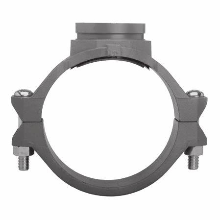
103 OUTLET FITTINGS 101 Outlet Fittings
104 102 OUTLET FITTINGS Figure 522 Sprinkler Outlet 1 of 2 B C D A Nominal Pipe Size Nominal Run Size / / (33,7) (42,4) (48,3) (60,3) Outlet Size NPT or ISO 7-1 Pipe Threads 1/2 3/4 1 3/8 1/2 3/4 1 1/2 3/4 1 1/2 3/4 1 Max. a Outlet End Load Lbs. (kn) 1.9 (0,738) (1,156) (1,156) 1.9 (0,738) 1.9 (0,738) (1,156) (1,81) 1.9 (0,738) (1,156) (1,81) 1.9 (0,738) (1,156) (1,81) Nominal Dimensions A B C D E 1.00 (25,4) 1.64 (41,7) 1.83 (46,5) 1.22 (31,0) 1.22 (31,0) 1.83 (46,5) 2.00 (50,8) 1.32 (33,5) 1.93 (49,0) 2.11 (53,6) 1.56 (39,6) 2.17 (55,1) 2.35 (60,0) 3.40 (86,4) 3.40 (86,4) 3.40 (86,4) 3.78 (96,0) 3.78 (96,0) 3.78 (96,0) 3.78 (96,0) 4.00 (101,6) 4.00 (101,6) 4.00 (101,6) 4.46 (113,3) 4.46 (113,3) 4.46 (113,3) 1.94 (49,3) 1.94 (49,3) 2.25 (57,2) 2.25 (57,2) 2.25 (57,2) 2.25 (57,2) 2.25 (57,2) 2.25 (57,2) 2.25 (57,2) 2.25 (57,2) 2.25 (57,2) 2.25 (57,2) 2.50 (63,5) 0.56 (14,3) 1.14 (29,0) 1.26 (32,0) 0.91 (23,1) 0.78 (19,8) 1.33 (33,8) 1.44 (36,6) 0.88 (22,4) 1.00 (25,4) 1.00 (25.4) 1.00 (25,4) 1.06 (26,9) 1.06 (26,9) 1.06 (26,9) 1.06 (26,9) 1.25 (31,8) 1.43 (36,3 (31,8) (39,4) 1.12 (28,4) 1.67 (42,4) 1.79 (45,5) 1.25 (31,8) 1.50 (38,1) 1.50 (38,1) 1.50 (38,1) a. Maximum pressure and end load are total from all loads based on standard weight steel pipe. Pressure ratings and end loads may differ on other pipe materials and/or wall thickness. Always confirm compatibility by contacting TYCO Fire Protection Products for details. Refer to Technical Data Sheet TFP18 for more information. E Approx. Wgt. Lbs (kg) 0.9 (0,4) 1.1 (0,5) 1.1 (0,5) 0.9 (0,4) 0.9 (0,4) 1.1 (0,5) 1.3 (0,6) 1.1 (0,5) 3.1 (0,5) 1.3 (0,6) 1.3 (0,6) 1.5 (0,7) 1.5 (0,7)
105 OUTLET FITTINGS 103 Figure 522 Sprinkler Outlet 2 of 2 B C D A Nominal Pipe Size Nominal Run Size () 2-1/2 76.1mm (73,0) (76,1) Outlet Size NPT or ISO 7-1 Pipe Threads 1/2 3/4 1 1/2 3/4 1 Max. a Outlet End Load Lbs. (kn) 1.9 (0,738) (1,156) (1,81) 1.9 (0,738) (1,156) (1,81) Nominal Dimensions A B C D E 2.00 (50,8) 5.12 (130,0) (63,5) (130,0) 2.70 (68,6) 2.00 (50,8) 2.25 (57,2) 2.25 (57,2) (130,0) (63,5) 5.12 (130,0) (63,5) (130,0) 2.75 (69,9) 2.25 (57,2) 2.25 (57,2) (130,0) (63,5) 1.56 (39,6) 2.00 (50,8) 2.14 (54,4) 1.56 (39,6) 2.00 (50,8) 2.19 (55,6) 1.69 (42,9) 1.69 (42,9) 1.69 (42,9) 1.82 (46,2) 1.82 (46,2) 1.82 (46,2) a. Maximum pressure and end load are total from all loads based on standard weight steel pipe. Pressure ratings and end loads may differ on other pipe materials and/or wall thickness. Always confirm compatibility by contacting TYCO Fire Protection Products for details. Refer to Technical Data Sheet TFP18 for more information. E Approx. Wgt. Lbs (kg) 1.5 (0,7) 1.8 (0,8) 1.8 (0,8) 1.5 (0,7) 1.8 (0,8) 1.8 (0,8)
106 104 OUTLET FITTINGS Figure 730 Threaded Mechanical Tees & Crosses D B C B C 1 of 10 A E D D A A FIGURE 730 TEE THREADED OUTLET Nominal Run x Branch FIGURE 730 CROSS THREADED OUTLET Nominal Dimensions- A B C D E 2 x 1/2 50 x 15 2 x 3/4 50 x 20 2 x 1 50 x 25 2 x 1-1/4 50 x 32 2 x 1-1/2 50 x /2 x 1/2 x /2 x 3/4 x /2 x 1 x /2 x 1-1/4 x /2 x 1-1/2 x /2 x 2 x 50 76,1mm x 1/2 x 15 76,1mm x 3/4 x 20 76,1mm x 1 x x (60,3 x 21,3) x (60,3 x 26,7) x (60,3 x 33,7) x (60,3 x 42,2) x (60,3 x 48,3) x (73,0 x 21,3) x (73,0 x 26,7) x (73,0 x 33,7) x (73,0 x 42,2) x (73,0 x 48,3) x (73,0 x 60,3) x (76,1 x 21,3) x (76,1 x 26,7) x (76,1 x 33,7) 2.62 (66,5) 2.62 (66,5) 2.62 (66,5) 2.78 (70,6) 2.75 (69,9) 2.88 (73,2) 2.88 (73,2) 2.88 (73,2) 3.00 (76,2) 3.07 (78,0) 3.19 (81,0) 2.94 (74,5) 2.94 (74,5) 2.94 (74,5) 4.88 (124,0) 4.88 (124,0) 4.88 (124,0) 4.88 (124,0) 4.88 (124,0) 5.25 (133,4) 5.25 (133,4) 5.25 (133,4) 5.25 (133,4) 5.25 (133,4) 5.25 (133,4) 5.62 (142,7) 5.62 (142,7) 5.62 (142,7) 3.07 (78,0) 3.07 (78,0) 3.07 (78,0) 3.32 (84,3) 3.32 (84,3) 3.07 (78,0) 3.07 (78,0) 3.07 (78,0) 3.56 (90,4) 3.59 (91,2) 4.00 (101,6) 3.07 (78,0) 3.07 (78,0) 3.07 (78,0) 2.12 (53,8) 2.12 (53,8) 2.12 (53,8) 1.93 (49,0) 1.93 (49,0) 2.38 (60,5) 2.38 (60,5) 2.38 (60,5) 2.19 (55,6) 2.17 (55,1) 2.44 (62,0) 2.44 (62,0) 2.44 (62,0) 2.44 (62,0) 1.59 (40,4) 1.59 (40,4) 1.59 (40,4) 1.59 (40,4) 1.59 (40,4) 1.81 (46,0) 1.81 (46,0) 1.81 (46,0) 1.81 (46,0) 1.81 (46,0) 1.81 (46,0) 1.87 (47,5) 1.87 (47,5) 1.87 (47,5) a. Pressure ratings are based on pipe schedule, pipe size, and approval agency. Approved pressure ratings start on page 142. Refer to Technical Data Sheet TFP1860 for more information.
107 OUTLET FITTINGS Figure 730 Threaded Mechanical Tees & Crosses D B C B C of 10 A E D D A A FIGURE 730 TEE THREADED OUTLET Nominal Run x Branch 2 x 1/2 50 x 15 2 x 3/4 50 x 20 2 x 1 50 x 25 2 x 1-1/4 50 x 32 2 x 1-1/2 50 x /2 x 1/2 x /2 x 3/4 x /2 x 1 x /2 x 1-1/4 x /2 x 1-1/2 x /2 x 2 x 50 76,1mm x 1/2 x 15 76,1mm x 3/4 x 20 76,1mm x 1 x x (60,3 x 21,3) x (60,3 x 26,7) x (60,3 x 33,7) x (60,3 x 42,2) x (60,3 x 48,3) x (73,0 x 21,3) x (73,0 x 26,7) x (73,0 x 33,7) x (73,0 x 42,2) x (73,0 x 48,3) x (73,0 x 60,3) x (76,1 x 21,3) x (76,1 x 26,7) x (76,1 x 33,7) Hole Diameter b Min. Max (44,5) (47,6) (38,1) (41,3) (38,1) (41,3) (44,5) (47,6) (44,5) (47,6) (38,1) (41,3) (38,1) (41,3) (38,1) (41,3) (50,8) (54,0) (50,8) (54,0) (50,8) (54,0) (38,1) (41,3) (38,1) (41,3) 1.50 (38,1) FIGURE 730 CROSS THREADED OUTLET 1.63 (41,3) Bolt c Size 3/8 x 2-1/4 (M10 x 57) 3/8 x 2-1/4 (M10 x 57) 3/8 x 2-1/4 (M10 x 57) 3/8 x 2-1/4 (M10 x 57) 3/8 x 2-1/4 (M10 x 57) 3/8 x 2-1/4 (M10 x 57) 3/8 x 2-1/4 (M10 x 57) 3/8 x 2-1/4 (M10 x 57) 3/8 x 2-1/4 (M10 x 57) 3/8 x 2-1/4 (M10 x 57) 3/8 x 2-1/4 (M10 x 57) (M10 x 57) (M10 x 57) (M10 x 57) Approx. Weight Lbs. (kg) b. Proper outlet hole preparation is required for effective sealing and performance. Inspect the pipe seal surface within 5/8 inch (15,9 mm) of the hole to ensure it is free from conditions that would adversely affect proper gasket sealing. Remove any sharp or rough edges from the hole or upper housing contact area that might affect assembly, proper seating of the locating collar or flow from the outlet. For Mechanical Crosses, ensure double outlet holes are aligned on opposite sides of the pipe. The use of threaded components other than steel pipe, such as dry type sprinklers, etc., may not be compatible with the female threaded outlets of Mechanical Tees and Crosses. Always confirm compatibility by contacting your TYCO Fire Protection Products Technical Services representative. c. Gold color coded metric bolt sizes are available upon request. Tee 2.5 (1,1) 2.3 (1,0) 2.2 (1,0) 2.4 (1,1) 2.5 (1,1) 2.4 (1,1) 2.4 (1,1) 2.4 (1,1) 2.5 (1,1) 2.6 (1,2) 2.7 (1,2) 2.5 (1,1) 2.5 (1,1) 2.5 (1,1) Cross 3.4 (1,5) 3.0 (1,4) 3.2 (1,5) 3.4 (1,5) 3.9 (1,8) 3.4 (1,5) 3.4 (1,5) 3.4 (1,5) 3.8 (1,7) 4.1 (1,9) 4.1 (1,9) 3.5 (1,6) 3.5 (1,6) 3.5 (1,6)
108 106 OUTLET FITTINGS Figure 730 Threaded Mechanical Tees & Crosses D B C B C 3 of 10 A E D D A A FIGURE 730 TEE THREADED OUTLET Nominal Run x Branch FIGURE 730 CROSS THREADED OUTLET Nominal Dimensions- A B C D E 76,1mm x 1-1/4 x 32 76,1mm x 1-1/2 x 40 76,1mm x 2 x 50 3 x 1/2 80 x 15 3 x 3/4 80 x 20 3 x 1 80 x 25 3 x 1-1/4 80 x 32 3 x 1-1/2 80 x 40 3 x 2 80 x 50 4 x 1/2 100 x 15 4 x 3/4 100 x 20 4 x x 25 4 x 1-1/4 100 x 32 4 x 1-1/2 100 x x (76,1 x 42,2) x (76,1 x 48,3) x (76,1 x 60,3) x (88,9 x 21,3) x (88,9 x 26,7) x (88,9 x 33,7) x (88,9 x 42,2) x (88,9 x 48,3) x (88,9 x 60,3) x (114,3 x 21,3) x (114,3 x 26,7) x (114,3 x 33,7) x (114,3 x 42,2) x (114,3 x 48,3) 3.06 (77,7) 3.13 (79,5) 3.25 (82,6) 3.19 (81,0) 3.19 (81,0) 3.19 (81,0) 3.34 (84,8) 3.38 (85.9) 3.50 (88,9) 3.69 (93,7) 3.69 (93,7) 3.69 (93,7) 3.92 (99,6) 4.00 (101,6) 5.62 (142,7) 5.62 (142,7) 5.62 (142,7) 6.13 (155,7) 6.13 (155,7) 6.13 (155,7) 6.13 (155,7) 6.13 (155,7) 6.13 (155,7) 7.13 (181,1) 7.13 (181,1) 7.13 (181,1) 7.13 (181,1) 7.13 (181,1) 3.56 (90,4) 3.56 (90,4) 4.00 (101,6) 3.07 (78,0) 3.07 (78,0) 3.07 (78,0) 3.32 (84,3) 3.56 (90,4) 4.09 (103,9) 3.07 (78,0) 3.07 (78,0) 3.07 (78,0) 3.32 (84,3) 3.56 (90,4) 2.25 (57,2) 2.25 (57,2) 2.50 (63,5) 2.56 (,0) 2.56 (,0) 2.56 (,0) 2.50 (63,5) 2.48 (63,0) 2.75 (69,9) 3.06 (77,7) 3.06 (77,7) 3.06 (77,7) 3.00 (76,2) 2.98 (75,7) 1.87 (47,5) 1.87 (47,5) 1.87 (47,5) 2.21 (56,1) 2.21 (56,1) 2.21 (56,1) 2.21 (56,1) 2.21 (56,1) 2.21 (56,1) 2.78 (70,6) 2.78 (70,6) 2.78 (70,6) 2.78 (70,6) 2.78 (70,6) a. Pressure ratings are based on pipe schedule, pipe size, and approval agency. Approved pressure ratings start on page 142. Refer to Technical Data Sheet TFP1860 for more information.
109 OUTLET FITTINGS Figure 730 Threaded Mechanical Tees & Crosses D B C B C of 10 A E D D A A FIGURE 730 TEE THREADED OUTLET Nominal Run x Branch 76,1mm x 1-1/4 x x (76,1 x 42,2) 76,1mm x 1-1/ x x 40 (76,1 x 48,3) 76,1mm x x x 50 (76,1 x 60,3) 3 x 1/ x x 15 (88,9 x 21,3) 3 x 3/ x x 20 (88,9 x 26,7) 3 x x x 25 (88,9 x 33,7) 3 x 1-1/ x x 32 (88,9 x 42,2) 3 x 1-1/ x x 40 (88,9 x 48,3) 3 x x x 50 (88,9 x 60,3) 4 x 1/ x x 15 (114,3 x 21,3) 4 x 3/ x x 20 (114,3 x 26,7) 4 x x x 25 (114,3 x 33,7) 4 x 1-1/ x x 32 (114,3 x 42,2) 4 x 1-1/ x x 40 (114,3 x 48,3) Hole Diameter b Min. Max (50,8) (54,0) (50,8) (54,0) (50,8) (54,0) (38,1) (41,3) (38,1) (41,3) (38,1) (41,3) (44,5) (47,6) (50,8) (54,0) (44,5) (47,6) (38,1) (41,3) (38,1) (41,3) (38,1) (41,3) (44,5) (47,6) 2.00 (50,8) FIGURE 730 CROSS THREADED OUTLET 2.13 (54,0) Bolt c Size (M10 x 57) (M10 x 57) (M10 x 57) 1/2 x 3 (M12 x 76) 1/2 x 3 (M12 x 76) 1/2 x 3 (M12 x 76) 1/2 x 3 (M12 x 76) 1/2 x 3 (M12 x 76) 1/2 x 3 (M12 x 76) 1/2 x 3 (M12 x 76) 1/2 x 3 (M12 x 76) 1/2 x 3 (M12 x 76) 1/2 x 3 (M12 x 76) 1/2 x 3 (M12 x 76) Approx. Weight Lbs. (kg) b. Proper outlet hole preparation is required for effective sealing and performance. Inspect the pipe seal surface within 5/8 inch (15,9 mm) of the hole to ensure it is free from conditions that would adversely affect proper gasket sealing. Remove any sharp or rough edges from the hole or upper housing contact area that might affect assembly, proper seating of the locating collar or flow from the outlet. For Mechanical Crosses, ensure double outlet holes are aligned on opposite sides of the pipe. The use of threaded components other than steel pipe, such as dry type sprinklers, etc., may not be compatible with the female threaded outlets of Mechanical Tees and Crosses. Always confirm compatibility by contacting your TYCO Fire Protection Products Technical Services representative. c. Gold color coded metric bolt sizes are available upon request. Tee 3.3 (1,5) 3.6 (1,6) 3.7 (1,7) 3.7 (1,7) 3.7 (1,7) 3.7 (1,7) 3.5 (1,6) 3.7 (1,7) 4.7 (2,1) 4.8 (2,2) 4.8 (2,2) 4.8 (2,2) 4.8 (2,2) 5.1 (2,3) Cross 5.1 (2,3) 5.7 (2,6) 5.8 (2,6) 5.2 (2,4) 5.2 (2,4) 5.2 (2,4) 4.6 (2,1) 5.2 (2,4) 6.8 (3,1) 5.6 (2,5) 5.6 (2,5) 5.6 (2,5) 5.6 (2,5) 6.4 (2,5)
110 108 OUTLET FITTINGS Figure 730 Threaded Mechanical Tees & Crosses D B C B C 5 of 10 A E D D A A FIGURE 730 TEE THREADED OUTLET Nominal Run x Branch FIGURE 730 CROSS THREADED OUTLET Nominal Dimensions- A B C D E 4 x x x (114,3 x 60,3) 4 x 2-1/ x x (114,3 x 73,0) 4 x 76,1mm x x (114,3 x 76,1) 4 x x x 80 (114,3 x 88,9) 5 x 1-1/ x x 40 (141,3 x 48,3) 5 x x x 50 (141,3 x 60,3) 5 x 2-1/ x x (141,3 x 73,0) 5 x 76,1mm x x (141,3 x 76,1) 5 x x x 80 (141,3 x 88,9) 139,7mm x 1-1/ x x 40 (139,7 x 48,3) 139,7mm x x x 50 (139,7 x 60,3) 139,7mm x 2-1/ x x (139,7 x 73,0) 139,7mm x 76,1mm x x (139,7 x 76,1) 139,7mm x x x 80 (139,7 x 88,9) 4.00 (101,6) 4.00 (101,6) 4.00 (101,6) 4.13 (104,9) 4.63 (117,6) 4.63 (117,6) 4.75 (120,7) 4.75 (120,7) 5.00 (127,0) 4.63 (117,6) 4.63 (117,6) 4.75 (120,7) 4.75 (120,7) 5.00 (127,0) 7.13 (181,1) 7.13 (181,1) 7.13 (181,1) 7.13 (181,1) 8.13 (206,5) 8.13 (206,5) 8.13 (206,5) 8.13 (206,5) 8.13 (206,5) 8.13 (206,5) 8.13 (206,5) 8.13 (206,5) 8.13 (206,5) 8.13 (206,5) 4.06 (103,1) 4.38 (111,3) 4.38 (111,3) 5.13 (130,3) 3.56 (90,4) 4.06 (103,1) 4.38 (111,3) 4.38 (111,3) 5.13 (130,3) 3.56 (90,4) 4.06 (103,1) 4.38 (111,3) 4.38 (111,3) 5.13 (130,3) 3.25 (82,6) 3.12 (79,2) 3.12 (79,2) 3.31 (84,1) 4.00 (101,6) 3.88 (98,6) 3.88 (98,6) 3.88 (98,6) 4.06 (103,1) 4.00 (101,6) 3.88 (98,6) 3.88 (98,6) 3.88 (98,6) 4.06 (103,1) 2.78 (70,6) 2.78 (70,6) 2.78 (70,6) 2.78 (70,6) 3.37 (85,6) 3.37 (85,6) 3.37 (85,6) 3.37 (85,6) 3.37 (85,6) 3.37 (85,6) 3.37 (85,6) 3.37 (85,6) 3.37 (85,6) 3.37 (85,6) a. Pressure ratings are based on pipe schedule, pipe size, and approval agency. Approved pressure ratings start on page 142. Refer to Technical Data Sheet TFP1860 for more information.
111 OUTLET FITTINGS Figure 730 Threaded Mechanical Tees & Crosses D B C B C of 10 A E D D A A FIGURE 730 TEE THREADED OUTLET Nominal Run x Branch 4 x x x (114,3 x 60,3) 4 x 2-1/ x x (114,3 x 73,0) 4 x 76,1mm x x (114,3 x 76,1) 4 x x x 80 (114,3 x 88,9) 5 x 1-1/ x x 40 (141,3 x 48,3) 5 x x x 50 (141,3 x 60,3) 5 x 2-1/ x x (141,3 x 73,0) 5 x 76,1mm x x (139,7 x 76,1) 5 x x x 80 (141,3 x 88,9) 139,7mm x 1-1/ x x 40 (139,7 x 48,3) 139,7mm x x x 50 (139,7 x 60,3) 139,7mm x 2-1/ x x (139,7 x 73,0) 139,7mm x 76,1mm x x (139,7 x 76,1) 139,7mm x x x 80 (139,7 x 88,9) Hole Diameter b Min. Max (63,5) (66,7) (69,9) (73,0) (69,9) (73,0) (88,9) (92,1) (50,8) (54,0) (63,5) (66,7) (69,9) (73,0) (69,9) (73,0) (88,9) (92,1) (50,8) (54,0) (63,5) (66,7) (69,9) (73,0) (69,9) (73,0) 3.50 (88,9) FIGURE 730 CROSS THREADED OUTLET 3.63 (92,1) Bolt c Size 1/2 x 3 (M12 x 76) 1/2 x 3 (M12 x 76) (M12 x 76) 1/2 x 3 (M12 x 76) 5/8 x 4-3/4 (M16 x 121) 5/8 x 4-3/4 (M16 x 121) 5/8 x 4-3/4 (M16 x 121) (M16 x 121) 5/8 x 4-3/4 (M16 x 121) (M16 x 121) (M16 x 121) (M16 x 121) (M16 x 121) (M16 x 121) Approx. Weight Lbs. (kg) Tee 5.5 (2,5) 6.2 (2,8) 6.2 (2,8) 7.8 (3,5) 7.8 (3,5) 7.8 (3,5) 8.9 (4,0) 8.9 (4,0) 12.7 (5,8) 7.8 (3,5) 7.8 (3,5) 8.9 (4,0) 8.9 (4,0) 12.7 (5,8) Cross 7.3 (3,3) 8.7 (3,9) 8.7 (3,9) 11.9 (5,4) 9.4 (4,3) 9.4 (4,3) 11.5 (5,2) 11.5 (5,2) 13.3 (6,0) 9.4 (4,3) 9.4 (4,3) 11.5 (5,2) 11.5 (5,2) 13.3 (6,0) b. Proper outlet hole preparation is required for effective sealing and performance. Inspect the pipe seal surface within 5/8 inch (15,9 mm) of the hole to ensure it is free from conditions that would adversely affect proper gasket sealing. Remove any sharp or rough edges from the hole or upper housing contact area that might affect assembly, proper seating of the locating collar or flow from the outlet. For Mechanical Crosses, ensure double outlet holes are aligned on opposite sides of the pipe. The use of threaded components other than steel pipe, such as dry type sprinklers, etc., may not be compatible with the female threaded outlets of Mechanical Tees and Crosses. Always confirm compatibility by contacting your TYCO Fire Protection Products Technical Services representative. c. Gold color coded metric bolt sizes are available upon request.
112 110 OUTLET FITTINGS Figure 730 Threaded Mechanical Tees & Crosses D B C B C 7 of 10 A E D D A A FIGURE 730 TEE THREADED OUTLET Nominal Run x Branch FIGURE 730 CROSS THREADED OUTLET Nominal Dimensions- A B C D E 6 x 1-1/4 x x (168,3 x 42,2) 6 x 1-1/ x x 40 (168,3 x 48,3) 6 x x x 50 (168,3 x 60,3) 6 x 2-1/ x x (168,3 x 73,0) 6 x 76,1mm x x (168,3 x 76,1) 6 x x x 80 (168,3 x 88,9) 6 x x x 100 (168,3 x 114,3) 1,1mm x 1-1/ x x 32 (1,1 x 42,2) 1,1mm x 1-1/ x x 40 (1,1 x 48,3) 1,1mm x x x 50 (1,1 x 60,3) 1,1mm x 2-1/ x x (1,1 x 73,0) 1,1mm x 76,1mm x x (1,1 x 76,1) 1,1mm x x x 80 (1,1 x 88,9) 8 x x x 50 (219,1 x 60,3) 5.13 (130,3) 5.13 (130,3) 5.13 (130,3) 5.13 (130,3) 5.13 (130,3) 5.50 (139,7) 5.38 (136,7) 5.13 (130,3) 5.13 (130,3) 5.13 (130,3) 5.13 (130,3) 5.13 (130,3) 5.50 (139,7) 6.25 (158,8) 9.25 (235,0) 9.25 (235,0) 9.25 (235,0) 9.25 (235,0) 9.25 (235,0) 9.25 (235,0) 9.25 (235,0) 9.25 (235,0) 9.25 (235,0) 9.25 (235,0) 9.25 (235,0) 9.25 (235,0) 9.25 (235,0) (317,5) 3.56 (90,4) 3.56 (90,4) 4.06 (103,1) 4.38 (111,3) 4.38 (111,3) 5.13 (130,3) 6.13 (155,7) 3.56 (90,4) 3.56 (90,4) 4.06 (103,1) 4.38 (111,3) 4.38 (111,3) 5.13 (130,3) 4.06 (103,1) 4.25 (108,0) 4.04 (102,6) 4.31 (109,5) 4.18 (106,2) 4.18 (106,2) 4.37 (111,0) 4.56 (115,8) 4.25 (108,0) 4.04 (102,6) 4.31 (109,5) 4.18 (106,2) 4.18 (106,2) 4.37 (111,0) 5.50 (139,7) 3.90 (99,1) 3.90 (99,1) 3.90 (99,1) 3.90 (99,1) 3.90 (99,1) 3.90 (99,1) 3.90 (99,1) 3.90 (99,1) 3.90 (99,1) 3.90 (99,1) 3.90 (99,1) 3.90 (99,1) 3.90 (99,1) 4.90 (124,5) a. Pressure ratings are based on pipe schedule, pipe size, and approval agency. Approved pressure ratings start on page 142. Refer to Technical Data Sheet TFP1860 for more information.
113 OUTLET FITTINGS Figure 730 Threaded Mechanical Tees & Crosses D B C B C of 10 A E D D A A FIGURE 730 TEE THREADED OUTLET Nominal Run x Branch 6 x 1-1/4 x x (168,3 x 42,2) 6 x 1-1/ x x 40 (168,3 x 48,3) 6 x x x 50 (168,3 x 60,3) 6 x 2-1/ x x (168,3 x 73,0) 6 x 76,1mm x x (168,3 x 76,1) 6 x x x 80 (168,3 x 88,9) 6 x x x 100 (168,3 x 114,3) 1,1 mmx 1-1/ x x 32 (1,1 x 42,2) 1,1 mmx 1-1/ x x 40 (1,1 x 48,3) 1,1mm x x x 50 (1,1 x 60,3) 1,1mm x 2-1/ x x (1,1 x 73,0) 1,1mm x 76, x x (1,1 x 76,1) 1,1mm x x x 80 (1,1 x 88,9) 8 x x x 50 (219,1 x 60,3) Hole Diameter b Min. Max (50,8) (54,0) (50,8) (54,0) (63,5) (66,7) (69,9) (73,0) (69,9) (73,0) (88,9) (92,1) (114,3) (117,5) (50,8) (54,0) (50,8) (54,0) (63,5) (66,7) (69,9) (73,0) (69,9) (73,0) (88,9) (92,1) 2.50 (63,5) FIGURE 730 CROSS THREADED OUTLET 2.63 (66,7) Bolt c Size 5/8 x 4-3/4 (M16 x 121) 5/8 x 4-3/4 (M16 x 121) 5/8 x 4-3/4 (M16 x 121) 5/8 x 4-3/4 (M16 x 121) 5/8 x 4-3/4 (M16 x 121) 5/8 x 4-3/4 (M16 x 121) 5/8 x 4-3/4 (M16 x 121) (M16 x 121) (M16 x 121) (M16 x 121) (M16 x 121) (M16 x 121) (M16 x 121) 3/4 x 4-3/4 (M20 x 121) Approx. Weight Lbs. (kg) b. Proper outlet hole preparation is required for effective sealing and performance. Inspect the pipe seal surface within 5/8 inch (15,9 mm) of the hole to ensure it is free from conditions that would adversely affect proper gasket sealing. Remove any sharp or rough edges from the hole or upper housing contact area that might affect assembly, proper seating of the locating collar or flow from the outlet. For Mechanical Crosses, ensure double outlet holes are aligned on opposite sides of the pipe. The use of threaded components other than steel pipe, such as dry type sprinklers, etc., may not be compatible with the female threaded outlets of Mechanical Tees and Crosses. Always confirm compatibility by contacting your TYCO Fire Protection Products Technical Services representative. c. Gold color coded metric bolt sizes are available upon request. Tee 7.5 (3,4) 7.5 (3,4) 7.7 (3,5) 8.9 (4,0) 8.9 (4,0) 10.3 (4,7) 11.9 (5,4) 7.7 (3,5) 7.7 (3,5) 8.2 (3,7) 9.0 (4,1) 9.0 (4,1) 10.5 (4,8) 12.1 (5,5) Cross 8.7 (3,9) 8.7 (3,9) 9.5 (4,3) 11.3 (5,1) 11.3 (5,1) 14.1 (6,4) 17.3 (9,1) 9.5 (4,3) 9.5 (4,3) 9.5 (4,3) 11.3 (5,1) 11.3 (5,1) 14.1 (6,4) 14.1 (6,4)
114 112 OUTLET FITTINGS Figure 730 Threaded Mechanical Tees & Crosses 9 of 10 D B C B C A D A E D A FIGURE 730 TEE THREADED OUTLET Nominal Run x Branch FIGURE 730 CROSS THREADED OUTLET Nominal Dimensions- A B C D E 8 x 2-1/2 200 x 8 x 76,1mm 200 x 8 x x 80 8 x x x (219,1 x 73,0) x (219,1 x 76,1) x (219,1 x 88,9) x (219,1 x 114,3) 6.25 (158,8) 6.25 (158,8) 6.50 (1,1) 6.38 (162,1) (317,5) (317,5) (317,5) (317,5) 4.38 (111,3) 4.38 (111,3) 5.13 (130,3) 6.13 (155,7) 5.12 (130,0) 5.12 (130,0) 5.37 (136,4) 5.56 (141,2) 4.90 (124,5) 4.90 (124,5) 4.90 (124,5) 4.90 (124,5) a. Pressure ratings are based on pipe schedule, pipe size, and approval agency. Approved pressure ratings start on page 142. Refer to Technical Data Sheet TFP1860 for more information.
115 OUTLET FITTINGS 113 Figure 730 Threaded Mechanical Tees & Crosses D B C B C 10 of 10 A E D D A A FIGURE 730 TEE THREADED OUTLET Nominal Run x Branch 8 x 2-1/2 200 x 8 x 76,1mm 200 x 8 x x 80 8 x x x (219,1 x 73,0) x (219,1 x 76,1) x (219,1 x 88,9) x (219,1 x 114,3) Hole Diameter b Min. Max (69,9) 2.75 (69,9) 3.50 (88,9) 4.50 (114,3) FIGURE 730 CROSS THREADED OUTLET 2.88 (73,0) 2.88 (73,0) 3.63 (92,1) 4.63 (117,5) Bolt c Size 3/4 x 4-3/4 (M20 x 121) (M20 x 121) 3/4 x 4-3/4 (M20 x 121) 3/4 x 4-3/4 (M20 x 121) Approx. Weight Lbs. (kg) b. Proper outlet hole preparation is required for effective sealing and performance. Inspect the pipe seal surface within 5/8 inch (15,9 mm) of the hole to ensure it is free from conditions that would adversely affect proper gasket sealing. Remove any sharp or rough edges from the hole or upper housing contact area that might affect assembly, proper seating of the locating collar or flow from the outlet. For Mechanical Crosses, ensure double outlet holes are aligned on opposite sides of the pipe. The use of threaded components other than steel pipe, such as dry type sprinklers, etc., may not be compatible with the female threaded outlets of Mechanical Tees and Crosses. Always confirm compatibility by contacting your TYCO Fire Protection Products Technical Services representative. c. Gold color coded metric bolt sizes are available upon request. Tee 12.6 (5,7) 12.6 (5,7) 13.6 (6,1) 15.2 (6,9) Cross 15.0 (6,8) 15.0 (6,8) 16.9 (7,7) 20.0 (9,1)
116 114 OUTLET FITTINGS Figure 730 Grooved Mechanical Tees & Crosses 1 of 8 B C B C A A E A FIGURE 730 TEE GROOVED OUTLET Nominal Run x Branch FIGURE 730 CROSS GROOVED OUTLET Nominal Dimensions- A B C E 2 x 1-1/4 50 x 32 2 x 1-1/2 50 x /2 x 1-1/4 x /2 x 1-1/2 x /2 x 2 x 50 76,1mm x 1 x 32 76,1mm x 1-1/4 x 32 76,1mm x 1-1/2 x 40 76,1mm x 2 x 50 3 x 1-1/4 80 x 32 3 x 1-1/2 80 x 40 3 x 2 80 x 50 4 x 1-1/4 100 x 32 4 x 1-1/2 100 x x (60,3 x 42,2) x (60,3 x 48,3) x (73,0 x 42,2) x (73,0 x 48,3) x (73,0 x 60,3) x (76,1 x 33,7) x (76,1 x 42,4) x (76,1 x 48,3) x (76,1 x 60,3) x (88,9 x 42,2) x (88,9 x 48,3) x (88,9 x 60,3) x (114,3 x 42,2) x (114,3 x 48,3) 2.78 (70,6) 2.62 (66,5) 3.00 (76,2) 3.07 (78,0) 3.19 (81,0) 2.94 (74,5) 3.06 (77,7) 3.13 (79,5) 3.25 (82,6) 3.34 (84,8) 3.38 (85,9) 3.50 (88,9) 3.92 (99,6) 4.00 (101,6) 4.88 (124,0) 4.88 (124,0) 5.25 (133,4) 5.25 (133,4) 5.25 (133,4) 5.62 (142,7) 5.62 (142,7) 5.62 (142,7) 5.62 (142,7) 6.13 (155,7) 6.13 (155,7) 6.13 (155,7) 7.13 (181,1) 7.13 (181,1) 3.32 (84,3) 3.32 (84,3) 3.56 (90,4) 3.59 (91,2) 4.00 (101,6) 3.07 (78,0) 3.56 (90,4) 3.56 (90,4) 4.00 (101,6) 3.32 (84,3) 3.56 (90,4) 4.09 (103,9) 3.32 (84,3) 3.56 (90,4) 1.59 (40,4) 1.59 (40,4) 1.81 (46,0) 1.81 (46,0) 1.81 (46,0) 1.87 (47,5) 1.87 (47,5) 1.87 (47,5) 1.87 (47,5) 2.21 (56,1) 2.21 (56,1) 2.21 (56,1) 2.78 (70,6) 2.78 (70,6) Pressure ratings are based on pipe schedule, pipe size, and approval agency. Approved pressure ratings start on page 152. Refer to Technical Data Sheet TFP1860 for more information.
117 OUTLET FITTINGS 115 Figure 730 Grooved Mechanical Tees & Crosses 2 of 8 B C B C A A E A FIGURE 730 TEE GROOVED OUTLET Nominal Run x Branch 2 x 1-1/4 50 x 32 2 x 1-1/2 50 x /2 x 1-1/4 x /2 x 1-1/2 x /2 x 2 x 50 76,1mm x 1 x 32 76,1mm x 1-1/4 x 32 76,1mm x 1-1/2 x 40 76,1mm x 2 x 50 3 x 1-1/4 80 x 32 3 x 1-1/2 80 x 40 3 x 2 80 x 50 4 x 1-1/4 100 x 32 4 x 1-1/2 100 x x (60,3 x 42,2) x (60,3 x 48,3) x (73,0 x 42,2) x (73,0 x 48,3) x (73,0 x 60,3) x (76,1 x 33,7) x (76,1 x 42,4) x (76,1 x 48,3) x (76,1 x 60,3) x (88,9 x 42,2) x (88,9 x 48,3) x (88,9 x 60,3) x (114,3 x 42,2) x (114,3 x 48,3) Hole Diameter a Min. Max (44,5) (47,6) (44,5) (47,6) (50,8) (54,0) (50,8) (54,0) (50,8) (54,0) (38,1) (41,3) (50,8) (54,0) (50,8) (54,0) (50,8) (54,0) (44,5) (47,6) (50,8) (54,0) (63,5) (66,7) (44,5) (47,6) 2.00 (50,8) 2.13 (54,0) FIGURE 730 CROSS GROOVED OUTLET Bolt b Size 3/8 x 2-1/4 (M10 x 57) 3/8 x 2-1/4 (M10 x 57) 3/8 x 2-1/4 (M10 x 57) 3/8 x 2-1/4 (M10 x 57) 3/8 x 2-1/4 (M10 x 57) (M10 x 57) (M10 x 57) (M10 x 57) (M10 x 57) 1/2 x 3 (M12 x 76) 1/2 x 3 (M12 x 76) 1/2 x 3 (M12 x 76) 1/2 x 3 (M12 x 76) 1/2 x 3 (M12 x 76) Approx. Weight Lbs. (kg) a. Proper outlet hole preparation is required for effective sealing and performance. Inspect the pipe seal surface within 5/8 inch (15,9 mm) of the hole to ensure it is free from conditions that would adversely affect proper gasket sealing. Remove any sharp or rough edges from the hole or upper housing contact area that might affect assembly, proper seating of the locating collar or flow from the outlet. For Mechanical Crosses, ensure double outlet holes are aligned on opposite sides of the pipe. b. Gold color coded metric bolt sizes are available upon request. Tee 2.5 (1,1) 2.4 (1,1) 2.5 (1,1) 2.5 (1,1) 2.5 (1,1) 2.5 (1,1) 2.5 (1,1) 2.5 (1,1) 2.5 (1,1) 3.5 (1,6) 3.6 (1,6) 4.5 (2,0) 4.8 (2,2) 5.0 (2,3) Cross 3.3 (1,5) 3.7 (1,7) 3.8 (1,7) 3.9 (1,8) 3.8 (1,7) 3.5 (1,6) 3.8 (1,7) 3.9 (1,8) 3.8 (1,7) 4.6 (2,1) 5.0 (2,3) 6.4 (2,9) 5.6 (2,5) 6.2 (2,8)
118 116 OUTLET FITTINGS Figure 730 Grooved Mechanical Tees & Crosses 3 of 8 B C B C A A E A FIGURE 730 TEE GROOVED OUTLET Nominal Run x Branch FIGURE 730 CROSS GROOVED OUTLET Nominal Dimensions- A B C E 4 x x x (114,3 x 60,3) 4 x 2-1/ x x (114,3 x 73,0) 4 x 76,1mm x x (114,3 x 76,1) 4 x x x 80 (114,3 x 88,9) 5 x 1-1/ x x 40 (141,3 x 48,3) 5 x x x 50 (141,3 x 60,3) 5 x 2-1/ x x (141,3 x 73,0) 5 x 76,1mm x x (141,3 x 76,1) 5 x x x 80 (141,3 x 88,9) 139,7mm x 1-1/ x x 40 (139,7 x 48,3) 139,7mm x x x 50 (139,7 x 60,3) 139,7mm x 2-1/ x x (139,7 x 73,0) 139,7mm x 76,1mm x x (139,7 x 76,1) 139,7mm x x x 80 (139,7 x 88,9) 4.00 (101,6) 4.00 (101,6) 4.00 (101,6) 4.13 (104,9) 4.63 (117,6) 4.63 (117,6) 4.75 (120,7) 4.75 (120,7) 5.00 (127,0) 4.63 (117,6) 4.63 (117,6) 4.75 (120,7) 4.75 (120,7) 5.00 (127,0) 7.13 (181,1) 7.13 (181,1) 7.13 (181,1) 7.13 (181,1) 8.13 (206,5) 8.13 (206,5) 8.13 (206,5) 8.13 (206,5) 8.13 (206,5) 8.13 (206,5) 8.13 (206,5) 8.13 (206,5) 8.13 (206,5) 8.13 (206,5) 4.06 (103,1) 4.38 (111,3) 4.38 (111,3) 5.13 (130,3) 3.56 (90,4) 4.06 (103,1) 4.38 (111,3) 4.38 (111,3) 5.13 (130,3) 3.56 (90,4) 4.06 (103,1) 4.38 (111,3) 4.38 (111,3) 5.13 (130,3) 2.78 (70,6) 2.78 (70,6) 2.78 (70,6) 2.78 (70,6) 3.37 (85,6) 3.37 (85,6) 3.37 (85,6) 3.37 (85,6) 3.37 (85,6) 3.37 (85,6) 3.37 (85,6) 3.37 (85,6) 3.37 (85,6) 3.37 (85,6) Pressure ratings are based on pipe schedule, pipe size, and approval agency. Approved pressure ratings start on page 152. Refer to Technical Data Sheet TFP1860 for more information.
119 OUTLET FITTINGS 117 Figure 730 Grooved Mechanical Tees & Crosses 4 of 8 B C B C A A E A FIGURE 730 TEE GROOVED OUTLET Nominal Run x Branch 4 x x x (114,3 x 60,3) 4 x 2-1/ x x (114,3 x 73,0) 4 x 76,1mm x x (114,3 x 76,1) 4 x x x 80 (114,3 x 88,9) 5 x 1-1/ x x 40 (141,3 x 48,3) 5 x x x 50 (141,3 x 60,3) 5 x 2-1/ x x (141,3 x 73,0) 5 x 76,1mm x x (141,3 x 76,1) 5 x x x 80 (141,3 x 88,9) 139,7mm x 1-1/ x x 40 (139,7 x 48,3) 139,7mm x x x 50 (139,7 x 60,3) 139,7mm x 2-1/ x x (139,7 x 73,0) 139,7mm x 76,1mm x x (139,7 x 76,1) 139,7mm x x x 80 (139,7 x 88,9) Hole Diameter a Min. Max (63,5) (66,7) (69,9) (73,0) (69,9) (73,0) (88,9) (92,1) (50,8) (54,0) (63,5) (66,7) (69,9) (73,0) (69,9) (73,0) (88,9) (92,1) (50,8) (54,0) (63,5) (66,7) (69,9) (73,0) (69,9) (73,0) 3.50 (88,9) 3.63 (92,1) FIGURE 730 CROSS GROOVED OUTLET Bolt b Size 1/2 x 3 (M12 x 76) 1/2 x 3 (M12 x 76) (M12 x 76) 1/2 x 3 (M12 x 76) 5/8 x 4-3/4 (M16 x 121) 5/8 x 4-3/4 (M16 x 121) 5/8 x 4-3/4 (M16 x 121) (M16 x 121) 5/8 x 4-3/4 (M16 x 121) (M16 x 121) (M16 x 121) (M16 x 121) (M16 x 121) (M16 x 121) Approx. Weight Lbs. (kg) a. Proper outlet hole preparation is required for effective sealing and performance. Inspect the pipe seal surface within 5/8 inch (15,9 mm) of the hole to ensure it is free from conditions that would adversely affect proper gasket sealing. Remove any sharp or rough edges from the hole or upper housing contact area that might affect assembly, proper seating of the locating collar or flow from the outlet. For Mechanical Crosses, ensure double outlet holes are aligned on opposite sides of the pipe. b. Gold color coded metric bolt sizes are available upon request. Tee 5.3 (2,4) 5.9 (2,7) 5.9 (2,7) 7.4 (3,4) 7.7 (3,5) 7.6 (3,4) 8.6 (3,9) 8.6 (3,9) 12.3 (5,6) 7.7 (3,5) 7.6 (3,4) 8.6 (3,9) 8.6 (3,9) 12.3 (5,6) Cross 6.9 (3,1) 8.2 (3,7) 8.2 (3,7) 11.1 (5,0) 9.2 (4,2) 9.0 (4,1) 11.0 (5,0) 11.0 (5,0) 12.5 (5,7) 9.2 (4,2) 9.0 (4,1) 11.0 (5,0) 11.0 (5,0) 12.5 (5,7)
120 118 OUTLET FITTINGS Figure 730 Grooved Mechanical Tees & Crosses 5 of 8 B C B C A A E A FIGURE 730 TEE GROOVED OUTLET Nominal Run x Branch FIGURE 730 CROSS GROOVED OUTLET Nominal Dimensions- A B C E 6 x 1-1/4 x x (168,3 x 42,2) 6 x 1-1/ x x 40 (168,3 x 48,3) 6 x x x 50 (168,3 x 60,3) 6 x 2-1/ x x (168,3 x 73,0) 6 x 76,1mm x x (168,3 x 76,1) 6 x x x 80 (168,3 x 88,9) 6 x x x 100 (168,3 x 114,3) 1,1mm x 1-1/ x x 32 (1,1 x 42,2) 1,1mm x 1-1/ x x 40 (1,1 x 48,3) 1,1mm x x x 50 (1,1 x 60,3) 1,1mm x 2-1/ x x (1,1 x 73,0) 1,1mm x 76,1mm x x (1,1 x 76,1) 1,1mm x x x 80 (1,1 x 88,9) 1,mm x x x 100 (1,1 x 114,1) 5.13 (130,3) 5.13 (130,3) 5.13 (130,3) 5.13 (130,3) 5.13 (130,3) 5.50 (139,7) 5.38 (136,7) 5.13 (130,3) 5.13 (130,3) 5.13 (130,3) 5.13 (130,3) 5.13 (130,3) 5.50 (139,7) 5.38 (136,7) 9.25 (235,0) 9.25 (235,0) 9.25 (235,0) 9.25 (235,0) 9.25 (235,0) 9.25 (235,0) 9.25 (235,0) 9.25 (235,0) 9.25 (235,0) 9.25 (235,0) 9.25 (235,0) 9.25 (235,0) 9.25 (235,0) 9.25 (235,0) 3.56 (90.4) 3.56 (90,4) 4.06 (103,1) 4.38 (111,3) 4.38 (111,3) 5.13 (130,3) 6.13 (155,7) 3.56 (90,4) 3.56 (90,4) 4.06 (103,1) 4.38 (111,3) 4.38 (111,3) 5.13 (130,3) 6.13 (155,7) 3.90 (99,1) 3.90 (99,1) 3.90 (99,1) 3.90 (99,1) 3.90 (99,1) 3.90 (99,1) 3.90 (99,1) 3.90 (99,1) 3.90 (99,1) 3.90 (99,1) 3.90 (99,1) 3.90 (99,1) 3.90 (99,1) 3.90 (99,1) Pressure ratings are based on pipe schedule, pipe size, and approval agency. Approved pressure ratings start on page 152. Refer to Technical Data Sheet TFP1860 for more information.
121 OUTLET FITTINGS 119 Figure 730 Grooved Mechanical Tees & Crosses 6 of 8 B C B C A A E A FIGURE 730 TEE GROOVED OUTLET Nominal Run x Branch 6 x 1-1/4 x x (168,3 x 42,2) 6 x 1-1/ x x 40 (168,3 x 48,3) 6 x x x 50 (168,3 x 60,3) 6 x 2-1/ x x (168,3 x 73,0) 6 x 76,1mm x x (168,3 x 76,1) 6 x x x 80 (168,3 x 88,9) 6 x x x 100 (168,3 x 114,3) 1,1mm x 1-1/ x x 32 (1,1 x 42,2) 1,1mm x 1-1/ x x 40 (1,1 x 48,3) 1,1mm x x x 50 (1,1 x 60,3) 1,1mm x 2-1/ x x (1,1 x 73,0) 1,1mm x 76,1mm x x (1,1 x 76,1) 1,1mm x x x 80 (1,1 x 88,9) 1,1mm x x x 100 (1,1 x 114,1) Hole Diameter a Min. Max (50,8) (54,0) (50,8) (54,0) (63,5) (66,7) (69,9) (73,0) (69,9) (73,0) (88,9) (92,1) (114,3) (117,5) (50,8) (54,0) (50,8) (54,0) (63,5) (66,7) (69,9) (73,0) (69,9) (73,0) (88,9) (92,1) 4.50 (114,3) 4.63 (117,5) FIGURE 730 CROSS GROOVED OUTLET Bolt b Size 5/8 x 4-3/4 (M16 x 121) 5/8 x 4-3/4 (M16 x 121) 5/8 x 4-3/4 (M16 x 121) 5/8 x 4-3/4 (M16 x 121) 5/8 x 4-3/4 (M16 x 121) 5/8 x 4-3/4 (M16 x 121) 5/8 x 4-3/4 (M16 x 121) (M16 x 121) (M16 x 121) (M16 x 121) (M16 x 121) (M16 x 121) (M16 x 121) (M16 x 121) Approx. Weight Lbs. (kg) a. Proper outlet hole preparation is required for effective sealing and performance. Inspect the pipe seal surface within 5/8 inch (15,9 mm) of the hole to ensure it is free from conditions that would adversely affect proper gasket sealing. Remove any sharp or rough edges from the hole or upper housing contact area that might affect assembly, proper seating of the locating collar or flow from the outlet. For Mechanical Crosses, ensure double outlet holes are aligned on opposite sides of the pipe. b. Gold color coded metric bolt sizes are available upon request. Tee 7.7 (3,5) 7.6 (3,4) 8.0 (3,6) 8.8 (4,0) 8.8 (4,0) 10.1 (4,6) 11.6 (5,3) 7.7 (3,5) 7.6 (3,4) 8.0 (3,6) 8.8 (4,0) 8.8 (4,0) 10.1 (4,6) 11.6 (5,3) Cross 9.5 (4,3) 9.3 (4,2) 9.1 (4,1) 10.8 (4,9) 10.8 (4,9) 13.3 (6,0) 16.3 (7,4) 9.5 (4,3) 9.3 (4,2) 9.1 (4,1) 10.8 (4,9) 10.8 (4,9) 13.3 (6,0) 16.3 (7,4)
122 120 OUTLET FITTINGS Figure 730 Grooved Mechanical Tees & Crosses 7 of 8 B C B C A A E A FIGURE 730 TEE GROOVED OUTLET Nominal Run x Branch FIGURE 730 CROSS GROOVED OUTLET Nominal Dimensions- A B C E 8 x x 50 8 x 2-1/2 200 x 8 x 76,1mm 200 x 8 x x 80 8 x x x (219,1 x 60,3) x (219,1 x 73,0) x (219,1 x 76,1) x (219,1 x 88,9) x (219,1 x 114,3) 6.25 (158,8) 6.25 (158,8) 6.25 (158,8) 6.50 (1,1) 6.38 (162,1) (317,5) (317,5) (317,5) (317,5) (317,5) 4.06 (103,1) 4.38 (111,3) 4.38 (111,3) 5.13 (130,3) 6.13 (155,7) 4.90 (124,5) 4.90 (124,5) 4.90 (124,5) 4.90 (124,5) 4.90 (124,5) Pressure ratings are based on pipe schedule, pipe size, and approval agency. Approved pressure ratings start on page 152. Refer to Technical Data Sheet TFP1860 for more information.
123 OUTLET FITTINGS 121 Figure 730 Grooved Mechanical Tees & Crosses 8 of 8 B C B C A A E A FIGURE 730 TEE GROOVED OUTLET Nominal Run x Branch 8 x x 50 8 x 2-1/2 200 x 8 x 76,1 200 x 8 x x 80 8 x x x (219,1 x 60,3) x (219,1 x 73,0) x (219,1 x 76,1) x (219,1 x 88,9) x (219,1 x 114,3) Hole Diameter a Min. Max (63,5) (66,7) (69,9) (73,0) (69,9) (73,0) (88,9) (92,1) 4.50 (114,3) 4.63 (117,5) FIGURE 730 CROSS GROOVED OUTLET Bolt b Size 3/4 x 4-3/4 (M20 x 121) 3/4 x 4-3/4 (M20 x 121) (M20 x 121) 3/4 x 4-3/4 (M20 x 121) 3/4 x 4-3/4 (M20 x 121) Approx. Weight Lbs. (kg) a. Proper outlet hole preparation is required for effective sealing and performance. Inspect the pipe seal surface within 5/8 inch (15,9 mm) of the hole to ensure it is free from conditions that would adversely affect proper gasket sealing. Remove any sharp or rough edges from the hole or upper housing contact area that might affect assembly, proper seating of the locating collar or flow from the outlet. For Mechanical Crosses, ensure double outlet holes are aligned on opposite sides of the pipe. b. Gold color coded metric bolt sizes are available upon request. Tee 12.1 (5,5) 12.3 (5,6) 12.3 (5,6) 13.2 (6,0) 14.7 (6,7) Cross 14.1 (6,4) 14.5 (6,6) 14.5 (6,6) 16.1 (7,3) 19.0 (8,6)
124 122 OUTLET FITTINGS Figure 40-5 Strap (Pipe Outlet) C A B D Nominal Run Size Outlet Size NPT Nominal Dimensions A B C D Approx. Weight Lbs. (kg) 1/ (50,8) 1.50 (38,1) 3.50 (88,9) 1.20 (30,5) 0.84 (0,4) 1-1/ (42,4) 3/ (50,8) 1.50 (38,1) 3.50 (88,9) 1.20 (30,5) 0.88 (0,4) (58,7) 1.68 (42,7) 3.50 (88,9) 1.20 (30,5) 1.13 (0,5) 1/ (53,8) 1.62 (41,1) 3.50 (88,9) 1.32 (33,5) 0.84 (0,4) 1-1/ (48,3) 3/ (53,8) 1.62 (41,1) 3.50 (88,9) 1.32 (33,5) 0.88 (0,4) (61,7) 1.80 (45,7) 3.50 (88,9) 1.32 (33,5) 1.13 (0,5) 1/ (59,9) 1.86 (47,2) 3.74 (95,0) 1.55 (39,4) 0.88 (0,4) (60,3) 3/ (59,9) 1.86 (47,2) 3.74 (95,0) 1.55 (39,4) 0.95 (0,4) (67,8) 2.04 (51,8) 3.74 (95,0) 1.55 (39,4) 1.16 (0,5) 1/ (66,3) 2.11 (53,6) 4.25 (108,0) 1.80 (45,7) 0.90 (0,4) 2-1/ (73,0) 3/ (66,3) 2.11 (53,6) 4.25 (108,0) 1.80 (45,7) 0.99 (0,5) (74,2) 2.29 (58,2) 4.25 (108,0) 1.80 (45,7) 1.21 (0,5) Outlet hole size in pipe is 1-3/16 inch (30,2 mm) diameter. Pressure ratings are based on pipe schedule, pipe size, and approval agency. Approved pressure ratings start on page 159. Refer to Technical Data Sheet TFP1720 for more information.

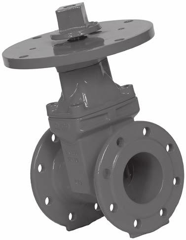
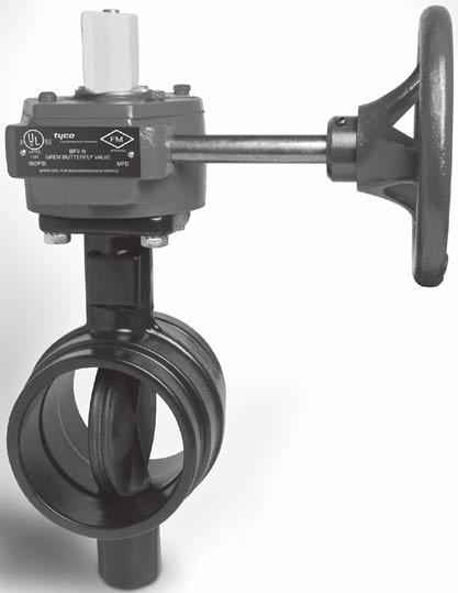
125 VALVES 123 Valves
Grooved Piping Products
 2 Grooved Piping Products Tyco Fire Products is ISO 9001 Certified with products manufactured in our newly constructed state of the art domestic ductile iron foundry and manufacturing facilities. We are
Grinnell Grooved Fire Protection Products Grooved Fittings
 Technical Services: Tel: (800) 38-932 / Fax: (800) 79-5500 www.tyco-fire.com Grinnell Grooved Fire Protection Products Grooved Fittings General Description LPCB Vd S The grooved fittings provide an economical
Technical Data. Sizes 2 in. to 24 in. (DN50 to DN600) Approvals UL and ULC Listed FM Approved
 Approvals UL and ULC Listed FM Approved") Worldwide Contacts www.tyco-fire.com Model TJP Resilient-Seated Gate Valves with Vertical or Cross Wall Post Indicator General Description TYCO Model TJP Resilient-Seated Gate Valves with Vertical and
Worldwide Contacts www.tyco-fire.com Model TJP Resilient-Seated Gate Valves with Vertical or Cross Wall Post Indicator General Description TYCO Model TJP Resilient-Seated Gate Valves with Vertical and
Product Submittals for Project
 Product Submittals for Project May 011-1 Couplings Figure 577 Light Weight Rigid Coupling For Fire Protection Pressure Rating and Listing / Approval information contact Tyco Fire Suppression & Building
Model CV-1FR Grooved-End Riser Check Valves 2 Inch to 12 Inch (DN50 to DN300) General Description. Installation. Technical Data
 General Description. Installation. Technical Data") Worldwide Contacts www.tyco-fire.com Model CV-FR Grooved-End Riser Check Valves Inch to Inch (DN0 to DN00) General Description The TYCO Model CV-FR Grooved- End Riser Check Valve is a compact and rugged
Worldwide Contacts www.tyco-fire.com Model CV-FR Grooved-End Riser Check Valves Inch to Inch (DN0 to DN00) General Description The TYCO Model CV-FR Grooved- End Riser Check Valve is a compact and rugged
B U I L D I N G C O N N E C T I O N S T H AT L A S T
 B U I L D I N G C O N N E C T I O N S T H AT L A S T pipe to pipe and people to people. We pride ourselves in providing the finest-quality pipe products and services with integrity and dedication to superior
Couplings. Ductile Iron Housing Specifications. Coatings. Gasket Specifications. Bolt/Nut Specifications
 Figure 71 Flange Adapters (ANSI Class 5/150) The Figure 71 Flange Adapter is capable of pressures up to 300 psi (20,7 bar) depending on pipe size and wall thickness. It provides a direct transition from
with the specific application. Always read and understand the installation
 Worldwide Contacts www.tyco-fire.com Resilient-Seated Gate Valves Outside Screw and Yoke General Description TYCO Resilient-Seated Gate Valves are used in Fire Protection Systems for on/off operation.
GRINNELL Model B302 and Model BN302 Grooved End Butterfly Valves with Gear Operators or Lever-Lock Operators General Description
 Worldwide Contacts www.grinnell.com GRINNELL Model B0 and Model BN0 Grooved End Butterfly Valves with Gear Operators or Lever-Lock Operators General Description The GRINNELL Model B0 and Model BN0 Butterfly
FIRE SPRINKLER EQUIPMENT SUBMITTAL
 Fire Systems West, Inc. 206 FRONTAGE ROAD NORTH, SUITE C PACIFIC, WA 98047 (253) 833-1248 FIRE SPRINKLER EQUIPMENT SUBMITTAL FOR Being 4-20-21 VPAL MAINTENANCE SHED AND SUBSTATION FSW JOB NO. 02-11-11013
GROOVED COUPLINGS - STANDARD FLEXIBLE Model 101
 GROOVED COUPLINGS - STANDARD FLEXIBLE Model 101 Available Sizes 1" through 12" (25 through ) Pipe Material Carbon steel, Schedule 10, Schedule 40. For use with alternative materials and wall thicknesses
The applicable material specifications for ductile iron and rubber gaskets apply:
 72 COUPLINGS - Grinnell Copper Grooved System is designed for joining copper tube size components 2" to 8" (54,0mm to 206,4mm) type K, L, M and DWV. All couplings and fittings are rated for working pressures
INTEGRATED PIPING SYSTEMS. Technical manual. Fire Protection
 INTEGRATED PIPING SYSTEMS Technical manual Fire Protection Disclaimer: This technical data is non-binding and may not reflect the guaranteed characteristics of the products, which are subject to change.
GRINNELL Model B303 Grooved End Butterfly Valves with Gear Operators or Lever-Lock Operators General Description
 Worldwide Contacts www.grinnell.com GRINNELL Model B Grooved End Butterfly Valves with Gear Operators or Lever-Lock Operators General Description The GRINNELL Model B Butterfly Valves provide for efficient
Advantages of Grooved Fittings
 Grooved Fittings Advantages of Grooved Fittings Comparative Advantages Allows angular deflection-misalignment Expansion, contraction or, no need for expansion joint Reclaimable, no need for union Allows
GRINNELL Model B302 and Model BN302 Grooved End Butterfly Valves with Gear Operators or Lever-Lock Operators General Description
 Technical Services -00- +-0--0 www.grinnell.com GRINNELL Model B0 and Model BN0 Grooved End Butterfly Valves with Gear Operators or Lever-Lock Operators General Description The GRINNELL Models B0 and BN0
FIG Gruvlok Flanges
 Gruvlok Flanges The Gruvlok Fig. 7012 Flange allows direct connection of Class 125 or Class 150 flanged components to a grooved piping system. The two interlocking halves of the 2" thru 12" sizes of the
Hole-cutting. cutting a hole. After the hole has been cut all rough edges must be removed and the area within 5/8 (16mm) of the hole
 of the hole") Mechanical Tees Hole-cutting Shurjoint mechanical tees provide a fast and easy mid-point branch outlet, eliminating the need for welding or the use of multiple fittings. The Model M21 features a female
Mechanical Tees Hole-cutting Shurjoint mechanical tees provide a fast and easy mid-point branch outlet, eliminating the need for welding or the use of multiple fittings. The Model M21 features a female
INTRODUCTION. General Notes
 INTRODUCTION Thank you for selecting a Shurjoint product. This manual covers the proper installation and assembly procedures for your product. To ensure the proper installation, assembly and performance
030/TL 03/01 50M, Copyright 2001, Anvil International $3. 50
 030/TL 03/01 50M, Copyright 2001, Anvil International $3. 50 Pipe Fitter Handbook Another Anvil Advantage Mini-catalog Installation Procedures Technical Data Copyright 2001 by Anvil International, Inc.
STAINLESS STEEL SYSTEMS
 STAINLESS STEEL SYSTEMS 139 Systems Table of Contents Figure 472 Rigid Couplings Page 142 Figure 401 45 Elbows Page 149 Figure SS-7X Rigid Couplings (Large Diameter) Page 143 Figure 405 Flexible Couplings
Mechanical MATERIAL SPECIFICATIONS. Stainless Steel Housing Specifications. Gasket Specifications. Bolt / Nut Specifications
 82 COUPLINGS SYSTEM The Grinnell Stainless Steel System is designed for joining 2" to 12" (54,0mm to 206,4mm) stainless steel piping, schedules 5, 10, and 40. The Figure 472 coupling patented Universal
Grooved End Fittings. System No. Submitted By Spec Sect Para Location Date Approved Date CARBON STEEL PIPE - GROOVED FITTINGS
 SEE VICTAULIC PUBLICATION 10.01 FOR DETAILS Victaulic offers a broad line of fittings in sizes through 60"/1500 in a variety of straight and reducing styles. Most standard fittings are cast of durable
TRUSTED FOR 150 YEARS
 G-2005 Today Anvil International is the largest and most complete fitting and hanger manufacturer in the world. 2004 Anvil International acquires Star Pipe Products, Building and Construction Divisions
GRINNELL MODEL CB800 CIRCUIT BALANCING VALVE INSTALLATION & SETTING HANDBOOK
 Technical Services 866-500-4768 +-40-78-8220 GRINNELL MODEL CB800 CIRCUIT BALANCING VALVE INSTALLATION & SETTING HANDBOOK AUGUST 20 IH-4500 Table of Contents Contents General Description.... 3 Dimensional
Style 234 Restrained Flexible Single-Gasket Coupling. System No. Submitted By Spec Sect Para Location Date Approved Date
 Victaulic Bolted Split-Sleeve Products (VBSP) Style 234 carbon steel couplings (formerly Depend-O-Lok Air/FluidMaster) are single-arch couplings that are commonly used in buried or exposed steel pipe applications
SECTION COMMON WORK RESULTS FOR FIRE SUPPRESSION. A. Pipe, fittings, valves, and connections for sprinkler systems.
 SECTION 210500 - COMMON WORK RESULTS FOR FIRE SUPPRESSION PART 1 GENERAL 1.1 SECTION INCLUDES A. Pipe, fittings, valves, and connections for sprinkler systems. 1.2 RELATED REQUIREMENTS A. Section 099000
FIG Gruvlok Flange Adapter
 FIG. 88 Gruvlok Adapter The Gruvlok Fig. 88 Adapter allows for direct connection of Class 125 or Class 150 flanged components to a grooved piping system. The Gruvlok Adapter provides an alternative method
Mechanical Piping Products
 October 202 For the most current product/pricing information on Anvil products, please visit our website at www.anvilintl.com. Mechanical Piping Products b u i l d i n g c o n n e c t i o n s t h a t l
Section 2. Shurjoint Grooved Fittings Flow Data / Friction Resistance Ductile Iron Grooved Fittings. Wrought Grooved Fittings
 Section 2 Cast & Wrought Grooved Fittings Shurjoint Grooved Fittings... 56 Flow Data / Friction Resistance... 56 Ductile Iron Grooved Fittings 7110 / 7111 / 7112 / 7113 Elbows... 57 7120 / 7135 / 7130
Grooved End Fittings. System No. Submitted By Spec Sect Para Location Date Approved Date CARBON STEEL PIPE - GROOVED FITTINGS
 SEE VICTAULIC PUBLICATION 10.01 FOR DETAILS Victaulic offers a broad line of fittings in sizes through 48 /1200 in a variety of straight and reducing styles. Most standard fittings are cast of durable
Model RM-1 Riser Manifold Commercial and Residential General Description
 Worldwide Contacts www.tyco-fire.com Model RM- Riser Manifold Commercial and Residential General Description The TYCO commercial and residential Model RM- Riser Manifold provide the necessary waterflow
Technical Data. Sizes 2 12 Inch (DN50 DN300)
") Worldwide Contacts www.tyco-fire.com Model BFV-/BFV-C Butterfly Valve Grooved End General Description The TYCO Models BFV- and BFV- C Grooved End Butterfly Valves are indicating type valves designed for
Worldwide Contacts www.tyco-fire.com Model BFV-/BFV-C Butterfly Valve Grooved End General Description The TYCO Models BFV- and BFV- C Grooved End Butterfly Valves are indicating type valves designed for
Worldwide Contacts. Technical Data
 Worldwide Contacts www.tyco-fire.com Model BFV-/BFV-C Butterfly Valve Grooved End General Description The TYCO Models BFV- and BFV- C Grooved End Butterfly Valves are indicating type valves designed for
Model 7706 Reducing Coupling. Deg. Axial Displacement
 MODEL 7706 REDUCING COUPLING The Model 7706 Reducing allows direct reduction on a piping run and eliminates the need for a concentric reducer and couplings. The specially designed rubber gasket prevents
Easy Riser swing check valve Models E-1 & F-1
 Page 1 of 7 1. DESCRIPTION The Viking Easy Riser Swing Check Valve is a general purpose rubber-faced approved for use in fire service systems. The valve is for use in wet system risers, preaction system
I-795/906. Series 795 and 906 Installation-Ready Knife Gate Valves WARNING INSTALLATION AND MAINTENANCE INSTRUCTIONS
 INSTALLATION AND MAINTENANCE INSTRUCTIONS I-795/906 Series 795 and 906 Installation-Ready Knife Gate Valves HANDWHEEL OPERATOR PNEUMATIC OPERATOR HYDRAULIC OPERATOR WARNING Read and understand all instructions
REQUEST PUBLICATION 18.11
 * SEE VICTALIC PBLICATION 10.01 FOR DETAILS The Victaulic Pressfit 316 System for joining approved Type 316/316L stainless steel pipe provides a fast, easy, clean, reliable means for joining ½"/15, ¾"/
TECHNICAL DATA OBSOLETE
 August 31, 2006 Check Valve 815a 1. PRODUCT NAME Viking Easy Riser Swing Check Valve Model E-1: Available since 1992 Model F-1: Available since 1994 2. MANUFACTURER The Viking Corporation 210 N. Industrial
Size Inches UL ULC FM. Pipe Sch.
 IPS CARBON STEEL PIPE - FIRE PROTECTION PRODUCTS FireLock Rigid Coupling STYLE 005 WITH VIC-PLUS GASKET SYSTEM (NORTH AMERICA ONLY) FireLock Style 005 rigid coupling has a unique, patented angle-pad design
1-1/2 Inch (DN40) 9 lb (4,1 kg) Groove Groove 1 8 lb (3,6 kg) Flange Groove 1 N/A N/A. Flange Flange N/A N/A
 9 lb (4,1 kg) Groove Groove 1 8 lb (3,6 kg) Flange Groove 1 N/A N/A. Flange Flange N/A N/A") Worldwide Contacts www.tyco-fire.com DV-5 Deluge Valve Diaphragm Style General Description The TYCO 1-1/2 inch to inch (DN40 to DN200), DV-5 Deluge Valves are diaphragm type valves designed for vertical
Worldwide Contacts www.tyco-fire.com DV-5 Deluge Valve Diaphragm Style General Description The TYCO 1-1/2 inch to inch (DN40 to DN200), DV-5 Deluge Valves are diaphragm type valves designed for vertical
Stainless Steel Pipe System. System No. Submitted By Spec Sect Para Location Date Approved Date TEMPERATURE ( F/ C)
") The Victaulic Vic-Press 304 System for joining approved Type 304/304L stainless steel pipe provides a fast, easy, clean, reliable means for joining 1/2"/15, 3/4"/20, 1"/25, 1 1/2"/40, and 2"/50 stainless
The Victaulic Vic-Press 304 System for joining approved Type 304/304L stainless steel pipe provides a fast, easy, clean, reliable means for joining 1/2"/15, 3/4"/20, 1"/25, 1 1/2"/40, and 2"/50 stainless
Typical Properties. Technical Data
 Worldwide Contacts www.tyco-fire.com LFP Antifreeze Agency Listed Solution for Fire Sprinkler Systems General Description LFP antifreeze is a pre-mixed freeze protection solution designed and listed for
I-232.T3S2 Victaulic Style 232 Restrained, Flexible High-Pressure Coupling
 WARNING Read and understand all instructions before attempting to install any Victaulic piping products. Depressurize and drain the piping system before attempting to install, remove, or adjust any Victaulic
September 2012 / M&H C502 / Model 129
 GENERAL FEATURES / GENERAL SPEC M&H AWWA C502 FIRE HYDRANTS Model 129 Traffic Model 250 PSI Working Pressure 500 PSI Hydrostatic Test AWWA UL / FM Approved Type: Compression type, opening against line
DV-5A Automatic Water Control Valve Remote-Resetting Deluge Fire Protection Systems 1-1/2 Inch to 8 Inch (DN40 to DN200) General Description
 General Description") Worldwide Contacts www.tyco-fire.com DV-5A Automatic Water Control Valve Remote-Resetting Deluge Fire Protection Systems 1-1/2 Inch to Inch (DN40 to DN200) General Description The TYCO DV-5A Automatic
Worldwide Contacts www.tyco-fire.com DV-5A Automatic Water Control Valve Remote-Resetting Deluge Fire Protection Systems 1-1/2 Inch to Inch (DN40 to DN200) General Description The TYCO DV-5A Automatic
Pellicon 2 and 3 Mini Holder. User Guide
 Pellicon 2 and 3 Mini Holder User Guide Notice The information in this document is subject to change without notice and should not be construed as a commitment by Millipore Corporation. Millipore Corporation
SEE VICTAULIC PUBLICATION FOR DETAILS
 dapters SEE VICTULIC PULICTION 10.01 FOR DETILS Style 741 Style 741 adapter is designed for directly incorporating flanged components with NSI CL. 125 or CL. 150/PN10 and PN16 or ustralian Standard Table
I-VICFLEX.AB11. Victaulic VicFlex Style AB11 Low-Profile Sprinkler Fitting for Suspended Ceiling Systems WARNING INSTALLATION INSTRUCTIONS
 INSTALLATION INSTRUCTIONS I-VICFLEX.AB11 Victaulic VicFlex Style AB11 Low-Profile Sprinkler Fitting for Suspended Ceiling Systems Read and understand all instructions before attempting to install any Victaulic
I-VICFLEX.AB5. Victaulic VicFlex Style AB5 Sprinkler Fitting for Wood or Metal Joists/Studs and CD Profile (60 mm) Channel Ceiling Systems WARNING
 Channel Ceiling Systems WARNING") INSTALLATION INSTRUCTIONS I-VICFLEX.AB5 Victaulic VicFlex Style AB5 Sprinkler Fitting for Wood or Metal Joists/Studs and CD Profile ( mm) Channel Ceiling Systems WARNING Read and understand all instructions
INSTALLATION INSTRUCTIONS I-VICFLEX.AB5 Victaulic VicFlex Style AB5 Sprinkler Fitting for Wood or Metal Joists/Studs and CD Profile ( mm) Channel Ceiling Systems WARNING Read and understand all instructions
IROn PIPe. McWane DUcTILe
 McWane DUcTILe IROn PIPe nsf 61 ISO 9001 DIPRa Boltless restrained joint systems Multiple design options available from 3 36 Fast and easy installation 350 pressure rating Independently tested www.mcwane.com
Section 3. Stainless Steel Series. Shurjoint Stainless Steel Piping Series Grooved Mechanical Couplings. Cast Grooved Fittings.
 Section 3 Stainless Steel Series Shurjoint Stainless Steel Piping Series... 84 Grooved Mechanical ouplings SS-5 Rigid oupling... 85 SS-7 Rigid oupling... 86 SS-7X Rigid oupling... 87 SS-8 Flexible oupling...
Instructions for Installation, Operation, Care and Maintenance
 Model D Dry Pipe Valve Bulletin 350 Rev. S Bulletin 350 Rev. S Instructions for Installation, Operation, Care and Maintenance 4 (100mm) 6 (150mm) Valve With Model D Trimmings Listed by Underwriters Laboratories,
DV-5 Deluge Valve Aluminium Bronze Diaphragm Style General Description
 Worldwide Contacts www.tyco-fire.com DV-5 Deluge Valve Aluminium Bronze Diaphragm Style General Description The TYCO Aluminum Bronze DV-5 Deluge Valves are available to provide an alternative material
I-234. Victaulic Styles 234/234S Restrained, Flexible Single-Gasket Couplings WARNING IMPORTANT INFORMATION ITEMS PROVIDED WITH SHIPMENT:
 WARNING Read and understand all instructions before attempting to install any Victaulic piping products. Depressurize and drain the piping system before attempting to install, remove, or adjust any Victaulic
GBV-G Balancing Valves
 Ductile Iron ASTM A6, Grade 6-4-2 The Series GBV is a multi-turn, Y-style globe valve designed for accurate determination and control of fluid flow to circuits requiring precise balancing. Max. Working
Ford Fabricated Steel Products
 Ford Fabricated Steel Products Section N2 12/2000 The Ford Meter Box Co., Inc. 775 Manchester Avenue, P.O. Box 443, Wabash, Indiana, USA 46992-0443 Telephone: 219/563-3171 FAX: 1-800-826-3487 Overseas
A. American National Standards Institute: 1. ANSI Z Relief Valves for Hot Water Supply Systems.
 SECTION 220523 - PLUMBING VALVES PART 1 - GENERAL 1.1 SUMMARY A. Section Includes: 1. Ball valves. 2. Butterfly valves. 3. Swing check valves. 4. Spring loaded check valves. 5. Water pressure reducing
QuickVic Rigid Coupling for Steel. System No. Submitted By Spec Sect Para Location Date Approved Date CARBON STEEL PIPE GROOVED COUPLINGS
 H ONL. SEE PAGE 4 FOR DETAILS. The patented Style 107 rigid coupling joins 12"/50 300 standard roll grooved and cut grooved steel pipe. The joint is assembled without disassembling the bolts, nuts, gasket
Victaulic Suction Vibration Isolation Pump Drop Series 337 Korea Only
 Victaulic Suction Vibration Isolation Pump Drop Series 337 Korea Only 2.37 1.0 PRODUCT DESCRIPTION Available Sizes 3 12"/DN80 DN300 Maimum Working Pressure Rated to the working pressure of the PN/PN16
Engineering Data. Assembly Length. How to Determine Correct Assembly Length
 Assembly Length How to Determine Correct Assembly Length For most assemblies, the correct assembly length may be determined by direct measurement of the equipment or a drawing. Minimum bend radii as shown
Directional Spray Nozzles, Open, with Strainers High Velocity General Description
 Worldwide Contacts www.tyco-fire.com Model FS Through F3S Mulsifyre Directional Spray Nozzles, Open, with Strainers High Velocity General Description The Model FS through F3S Mulsifyre Nozzles are open
TECHNICAL DATA. Q= C v P Cv = Flow Factor (GPM/1 PSI P)
") 1 of 9 1. DESCRIPTION The Viking 2 (DN50) is a quick-opening, differential diaphragm, flood valve with one moving part. The deluge valve is used to control water flow in deluge and preaction sprinkler
1 of 9 1. DESCRIPTION The Viking 2 (DN50) is a quick-opening, differential diaphragm, flood valve with one moving part. The deluge valve is used to control water flow in deluge and preaction sprinkler
TECHNICAL DATA. Q= C v P S
 1 of 9 1. DESCRIPTION The Viking Model E-1 Deluge Valve is a quick-opening, differential diaphragm, flood valve with one moving part. The deluge valve is used to control water flow in deluge and preaction
 18. KSP 18. KSP 18.1 1200016 1200016 18.2 18.3 1200016 1200016 18.4 18.5 1200016 1200016 18.6 18.7 1200016 1200016 18.8 18.9 1200016 DARLEY BASIC ASSEMBLING TECHNIQUES Work with clean tools in clean surroundings
INSTALLATION & MAINTENANCE GUIDE
 BUTTERFLY VALVES INSTALLATION & MAINTENANCE GUIDE L-1 GLOBE BUTTERFLY VALVE INSTALLATION AND MAINTENANCE GUIDE Table of Contents Page Design Requirements and Installation Care and Maintenance GL175T GL175G
Section 8 AMERICAN. Flanged Pipe
 Section 8 AMERICAN Flanged Pipe The principal standards covering Flanged Pipe are ANSI/AWWA C115/A21.15 and ANSI/AWWA C110/A21.10. These and other standards are referenced throughout this Section either
GRUVLOK FITTINGS FOR GROOVED-END PIPE
 GRUVLOK FITTINGS FOR GROOVED-END PIPE Gruvlok fittings are available through 24" nominal pipe size in a variety of styles. Use the Fitting Table to convert nominal pipe size to corresponding pipe These
4077 AIRPARK DRIVE STANDISH, MICHIGAN PHONE FAX
 Butterfly Valves 4077 AIRPARK DRIVE STANDISH, MICHIGAN 48658 PHONE 989-846-4583 FAX 989-846-9231 www.globesprinkler.com FEBRUARY 2010 L-1 BULLETIN BUTTERFLY REV# 4 GLOBE BUTTERFLY VALVE INSTALLATION AND
Pipe hanger solutions
 Product catalog Middle East offering Pipe hanger solutions for commercial and industrial applications B00 series B00 - Standard clevis hanger Pipe will not pinch when installing. 5 swing in either direction
I-VICFLEX.AB1/AB2/AB10
 INSTALLATION INSTRUCTIONS I-VICFLEX.AB1/AB/AB10 Victaulic VicFlex Flexible Hose with Fittings for Fire Protection Service Styles AB1, AB, and AB10 Brackets Flexible Hose Listing and Approval Information
SWING CHECK VALVES SERIES 52-SC SERIES 600
 SWING CHECK VALVES SERIES 52-SC SERIES 600 FEATURES/BENEFITS/SPECIFICATIONS AMERICAN Flow Control Series 52-SC Swing Check Valves incorporate design features to help increase service life for water and
contents MALLEABLE PIPE FITTINGS BUsHEs NiPPlEs PlUgs caps BENds BackNUTs UNioNs TEEs 171 cross PN25 p socket PN25 p socket PN25 p.
 contents BUsHEs 140 Hexagon Bush p.5 NiPPlEs 144 octagon Nipple p.6 145 Hexagon Nipple p.6 PlUgs 146 Beaded Plug - solid p.7 147 Plain Plug - Hollow p.7 148 Plain Plug - solid p.7 149 countersunk Plug
Instructions for Installation, Operation, Care and Maintenance
 Bulletin 407 Rev. T Model E Alarm Check Valve Bulletin 407 Rev. T Instructions for Installation, Operation, Care and Maintenance 4 (100 mm), 6 (150 mm), 8 (200 mm) Sizes With Model E3 Trim Listed by Underwriters
Model F822 thru F834 Mulsifyre Directional Spray Nozzles, Open, High Velocity General Description
 Technical Services: Tel: () 31-931 / Fax: () 791-55 Model F thru F3 Mulsifyre Directional Spray Nozzles, Open, High Velocity General Description The Mulsifyre Nozzles are open (nonautomatic) nozzles and
Flow Control. Before installation or maintenance, these instructions must be fully read and understood.
 Before installation or maintenance, these instructions must be fully read and understood. Please read these instructions carefully. This symbol indicates important messages and safety instructions. Potentially
KENNEDY VALVE RESILIENT WEDGE GATE VALVE MAINTENANCE MANUAL
 KENNEDY VALVE Division of McWane, Inc. 1021 East Water Street P.O. Box 931 Elmira, New York 14902-0931 Telephone (607) 734-2211 Fax (607) 734-1003 KENNEDY VALVE RESILIENT WEDGE GATE VALVE MAINTENANCE MANUAL
mh-valve.com 129 HYDRANT AWWA C502 NSF 61/372 CERTIFIED UL LISTED FM APPROVED 250 PSI WORKING PRESSURE 10-YEAR LIMITED WARRANTY
 mh-valve.com 129 HYDRANT AWWA C502 NSF 61/372 CERTIFIED UL LISTED FM APPROVED 250 PSI WORKING PRESSURE 10-YEAR LIMITED WARRANTY 129 HYDRANT YESTERDAY, TODAY, & TOMORROW For more than 85 years, the M&H
Piranha Restraint Gasket
 Document # 02-9-0005 07.23.2013 Piranha Restraint Gasket Joint Restraint for Tyton Ductile Iron Bell and Spigot Push-On Joints. occurred during transit and that no teeth are missing. Also check the diameter
Type D3S PROTECTOSPRAY Directional Spray Nozzles, Open, Medium Velocity General Description. Technical Data. Page 1 of 6 AUGUST 2018 TFP804
 Worldwide Contacts www.tyco-fire.com Type D3S PROTECTOSPRAY Directional Spray Nozzles, Open, Medium Velocity General Description The Type D3S Protectospray Nozzles are open (non-automatic) directional
SECTION VALVES
 PART 1 GENERAL 1.1 RELATED DOCUMENTS A. Drawings and general provisions of the Contract, including General and Supplementary Conditions Specification Sections, apply to this Section. B. Related Sections:
Instructions for Installation, Operation Care and Maintenance
 Model A Dry Pipe Valve Bulletin 353 Rev.K Bulletin 353 Rev.K Instructions for Installation, Operation Care and Maintenance 2 1 2 (65mm) Valve With Model A Trim Listed by Underwriters Laboratories, Inc.
Worldwide Contacts.
 Worldwide Contacts www.tyco-fire.com DV-5 Remote-Resetting, Pressure-Reducing Deluge Valve, Limited Space Valve Cabinet General Description The TYCO DV-5 Remote-Resetting, Pressure-Reducing Deluge Valve,
I-231.T2S1/CLAD. Victaulic Style 231 Non-Restrained, Flexible Expansion Coupling with Cladding on Expansion Side of Pipe WARNING IMPORTANT INFORMATION
 WARNING Read and understand all instructions before attempting to install any Victaulic piping products. Depressurize and drain the piping system before attempting to install, remove, or adjust any Victaulic
Section 7. Socket Weld and Threaded Fittings. Socket Weld and Threaded Fittings 7-1
 Section 7 Socket Weld and Threaded Fittings This Section contains dimension and tolerance information extracted from American and British specifications applicable to socket weld and threaded fittings.
Valve Selection. 1. Function and service considerations
 1. Function and service considerations Valve Selection Selection Valves serve the purpose of controlling the fluids in building services piping. Valves are produced in a variety of design types and materials.
GT-200 GATE VALVES PN16, Screwed end
 Document No. : MD-QO-04-281 Date : 2009/07 /17 Version : 1.0 GT-200 GATE VALVES PN16, Screwed end USER MANUAL Modentic Industrial Corporation 14F-1,No.57Taya Rd.,Taichung,Taiwan,R.O.C. Email:modentic@ms9.hinet.net
Herpteraium SECTION VALVES GENERAL
 SECTION 22 05 23 VALVES GENERAL 1.01 RELATED DOCUMENTS A. Drawings and general provisions of the Contract, including General and Supplementary Conditions and Division 01 Specification Sections, apply to
TECHNICAL DATA. Inlet Type Outlet Type OBSOLETE 6 (DN150)
") January 13, 2006 Deluge Valves 211 a 1. PRODUCT NAME Viking Model E-1 Deluge Valve 3 (DN80) Available since 1985 4 (DN100) Available since 1985 6 (DN150) Available since 1984 2. MANUFACTURER THE VIKING
January 13, 2006 Deluge Valves 211 a 1. PRODUCT NAME Viking Model E-1 Deluge Valve 3 (DN80) Available since 1985 4 (DN100) Available since 1985 6 (DN150) Available since 1984 2. MANUFACTURER THE VIKING
Housing Coating: Orange enamel. Hot dipped galvanized. Optional Bolts/Nuts: (Available in imperial size bolts and nuts only.)
") SEE VICTAULIC PUBLICATION 10.01 FOR DETAILS The patented Style 107H rigid coupling joins 8"/50 200 standard roll grooved and cut grooved steel pipe.* The joint is assembled without disassembling the bolts,
SEE VICTAULIC PUBLICATION 10.01 FOR DETAILS The patented Style 107H rigid coupling joins 8"/50 200 standard roll grooved and cut grooved steel pipe.* The joint is assembled without disassembling the bolts,
Victaulic Standard Grooved and Advanced Grooved (AGS) Piping System for IPS Steel 2 (DN 50) through 60 (DN1500)
 Piping System for IPS Steel 2 (DN 50) through 60 (DN1500)") Victaulic Standard Grooved and Advanced Grooved (AGS) Piping System for IPS Steel 2 (DN 50) through 60 (DN1500) 1.01 General: A. Section Includes: 1. General 2. Materials: a. Pipe b. Victaulic Couplings
Victaulic Standard Grooved and Advanced Grooved (AGS) Piping System for IPS Steel 2 (DN 50) through 60 (DN1500) 1.01 General: A. Section Includes: 1. General 2. Materials: a. Pipe b. Victaulic Couplings
SECTION GENERAL-DUTY VALVES FOR PLUMBING PIPING
 SECTION 220523 - GENERAL-DUTY VALVES FOR PLUMBING PIPING PART 1 - GENERAL 1.1 RELATED DOCUMENTS A. Drawings and general provisions of the Contract, including General and Supplementary Conditions and Division
Resilient-Seated Gate Valves with Vertical or Cross Wall Post Indicator
 Worldwide ontacts www.tyco-fire.com Resilient-Seated Gate Valves with Vertical or ross Wall Post Indicator General Description TYO Resilient-Seated Gate Valves with Vertical and ross Wall Indicators are
Resilient-Seated Gate Valves with Vertical or Cross Wall Post Indicator
 Worldwide ontacts www.tyco-fire.com Resilient-Seated Gate Valves with Vertical or ross Wall Post Indicator General Description TYO Resilient-Seated Gate Valves with Vertical and ross Wall Indicators are
K81-D FIRE HYDRANT GUARDIAN AWWA C502 NSF YEARS. For Generations CERTIFICATIONS ISO 9001 ISO BS OHSAS
 GUARDIAN K81-D FIRE HYDRANT CERTIFICATIONS ISO 9001 ISO 14001 BS OHSAS 18001 AWWA C502 NSF 61 140 YEARS WWW.KENNEDYVALVE.COM C For Generations COMPONENTS AND FEATURES A B C E D F G H J L M K N P Q S R
PROJ. NO SECTION HYDRONIC PUMPS
 SECTION 23 21 23 HYDRONIC PUMPS PART 1 - GENERAL 1.1 RELATED DOCUMENTS A. Drawings and general provisions of the Contract, including General and Supplementary Conditions and Division 01 Specification Sections,
AVK SERIES 41 SWING CHECK VALVE FIELD MAINTENANCE AND INSTRUCTION MANUAL FOR SWING CHECK VALVES 3" - 12"
 AMERICAN AVK COMPANY AVK SERIES 41 SWING CHECK VALVE FIELD MAINTENANCE AND INSTRUCTION MANUAL FOR SWING CHECK VALVES 3" - 12" TABLE OF CONTENTS EXPLODED ASSEMBLY / PARTS LIST INTRODUCTION / DESCRIPTION
Standard Specification for Threaded Couplings, Steel, Black or Zinc-Coated (Galvanized) Welded or Seamless, for Use in Steel Pipe Joints 1
 Welded or Seamless, for Use in Steel Pipe Joints 1") Designation: A 865 97 AMERICAN SOCIETY FOR TESTING AND MATERIALS 00 Barr Harbor Dr., est Conshohocken, PA 9428 Reprinted from the Annual Book of ASTM Standards. Copyright ASTM Standard Specification for
Designation: A 865 97 AMERICAN SOCIETY FOR TESTING AND MATERIALS 00 Barr Harbor Dr., est Conshohocken, PA 9428 Reprinted from the Annual Book of ASTM Standards. Copyright ASTM Standard Specification for