Couplings. Resilient and Soft Start Couplings. 4th Edition
|
|
|
- Darlene Dennis
- 6 years ago
- Views:
Transcription

1 Couplings Resilient and Soft Start Couplings 4th Edition
2 Clutches & Couplings Wentloog Corporate Park, Newlands Road, Cardiff CF3 2EU Wales Tel: +44 (0) Fax: +44 (0) (Sales): +44 (0) E-ail: Web: Products: Resilient Shaft Couplings, Gear and Fluid Soft-Start Couplings, Clutches: Sprag, Slipping and Air Types. Hi-Tec Couplings 112 Parkinson Lane, Halifax, West Yorkshire, HX1 3QH Tel: +44 (0) Fax: +44 (0) E-ail: Web: Products: Flexible and Resilient Shaft Couplings, Shaft to Shaft and Flywheel to Shaft, arine, Generator sets, Industrial Gears Holroyd Gears Works, ilnrow, Rochdale OL16 3LS England Tel: +44 (0) Fax: +44 (0) E-ail: Web: Products: Worm, Helical and Bevel-Helical Speed Reducer Gear Units, Geared otor Unit, Hydrostatic, echanical and Electronic Variable Speed Drives and Fully Engineered Package Drives. RENOLD Clutches and Couplings. Tel: + 44 (0) Fax: + 44 (0) E-ail: couplings@cc.renold.com
3 Contents Page No Company Profile 5 Typical Applications 6-7 Pictorial Contents 8-9 Gear Division Product Range 10 Coupling Selection Guide 11 Selections Taper Bushes 16 Spiderflex Spider 20 Pinflex Crownpin Tyreflex Discflex Chainflex Rigid 38 Gearflex Hydrastart Electric otor Shaft Dimensions 55 Renold Hi-Tec Coupling Range Renold Worldwide Sales & Services RENOLD Clutches and Couplings. Tel: + 44 (0) Fax: + 44 (0) E-ail: couplings@cc.renold.com 3

4


 became a member of Renold plc in 1996.")


5 Renold Clutches & Couplings Renold have been manufacturing flexible and rigid couplings, sprag and air clutches for over 50 years. The Renold Couplings factories are based in two UK locations, Cardiff and Halifax. Clutches & Couplings - Cardiff In 1991 the company moved to a purpose-built factory in Wentloog, Cardiff, in which state-of-the-art machining and inspection facilities are to be found, all supporting a high level of personal customer care. Special Solutions and Innovations Renold is recognised throughout the industry for its capability to create specific solutions to customers unique requirements. International companies and industries, from steel to food processing to escalators to textile machinery, have chosen Renold to solve their problems. Leading Edge Technology Renold provides practical cost effective solutions with a commitment to value through quality. This is achieved by the continuous investment in people, process technology and manufacturing. Service Excellence & Care Hi-Tec Couplings - Halifax The Halifax factory (formally Holset Engineering Ltd.) became a member of Renold plc in The operation also includes the latest machining and tooling technology with integrated cellular manufacturing and complete testing and balancing capabilities. All Renold Couplings are manufactured in the UK to Renold exacting standards. Renold offers a unique level of service excellence and customer care. Our experienced applications engineers will select the optimum solution, with the aid of the latest computer and design technology. Consistent Reliability Renold s 100 years of experience in the design and manufacturing of power transmission products to the highest specifications, with proven performance in diverse industries world-wide, underwrites the guaranteed quality and the assurance of reliability. Renold Clutches & Couplings is BS EN ISO 9001 approved. All products are designed and manufactured to this Quality Assurance System. Testing LRQA/ Certificate 9079 The organisation stretches worldwide Although each of our factories manufacturing and testing demands vary, the following capabilities are available if the application demands it: Full scale radial and axial stiffness measurement. Torsional vibration analysis. isalignment testing of couplings up to 2 metres diameter. easurements of torsional stiffness up to 220 KN Static and dynamic balancing capabilities. Noise attenuation testing. 16 National Sales Companies Transient and finite element analysis. Over 70 Overseas Distributors Offering the comprehensive range of power transmission products directly or through local distributor networks RENOLD Clutches and Couplings. Tel: + 44 (0) Fax: + 44 (0) E-ail: couplings@cc.renold.com 5


6 Flexible and Soft Start Couplings - Typical Applications Hydrastart A flexible coupling suitable for soft starting, high inertia machinery with reduced current demand, controlled acceleration, torque and motor overload protection. Ball ills Rotary Kilns Conveyors Fans Centrifuges Pinflex A robust general purpose pin/buffer coupling, providing reliable fail safe transmission of torque and misalignment capability. Pumps Compressors Conveyors Crown Pin An established pin/buffer coupling offering extended power capacity where the demand for long life and simplicity of construction make it suitable for working in arduous conditions. Conveyors Washers Pumps Screens Cranes General Industrial Application Spider Couplings Relatively low power but highly flexible coupling with halfbodies in either cast iron or bronze, making suitable for use in the food or chemical/pharmaceutical industries. Pumps ixers Lube Systems Gearflex Heavy duty all metal couplings giving maximum power capacity within minimum space envelope and excellent misalignment capacity. Steelworks Quarries ining RENOLD Clutches and Couplings. Tel: + 44 (0) Fax: + 44 (0) E-ail: couplings@cc.renold.com 6


7 Flexible and Soft Start Couplings - Typical Applications Discflex A general purpose, fail safe, torsionally flexible coupling offering the option of either urethane or reinforced rubber disc. Pumps Compressors Conveyors ixers Spiderflex A medium powered, torsionally flexible coupling, combining shock absorbing and misalignment. Used in the widest range of industries and applications. Tyreflex A range of highly flexible couplings offering excellent misalignment capacity and suitable to absorb both shock loads and vibrations. Pumps Compressors Diesel Engines Roller Tables RB 0.24 RB flywheel mounted coupling on a Deutz TD diesel generator set in Spain. Generator Sets Pump Sets Compressors Bulk Handling P 2 off P600 on a nickel grinding mill at Leinster in Western Australia. etal anufacturing Pumps Fans Compressors Pulp and Paper Cranes and hoists RENOLD Clutches and Couplings. Tel: + 44 (0) Fax: + 44 (0) E-ail: couplings@cc.renold.com 7

8 Pictorial Contents Spiderflex Coupling Spider Coupling The Interchangeable & Cost Effective Solution A medium powered torsionally flexible coupling, combining shock absorbing and misalignment capacity. Used in the widest range of industries and applications. ax 100 rpm: 35 ax Torque: 3308 Nm Page No 17 Pinflex Coupling The Cost Effective Solution Small powered, torsionally flexible coupling with shock absorbing and misalignment capacity. ax 100 rpm: 1.12 ax Torque: 107 Nm Page No 20 Crownpin Flexible Coupling The Popular Choice A robust general purpose pin/buffer coupling, providing reliable fail safe transmission of torque and misalignment capability. ax 100 rpm: 340 ax Torque: Nm Page No 21 Tyreflex Coupling The Reliable Solution An established pin/buffer coupling, offering extended power capacity where the demand for long life and simplicity of construction make it suitable for working in arduous conditions. ax 100 rpm: 2611 ax Torque: Nm Page No 26 Discflex Coupling The Interchangeable Resilient Solution A range of highly flexible couplings offering excellent misalignment capacity and suitable to absorb both shock loads and vibrations. ax 100 rpm: 65.8 ax Torque: 6270 Nm Page No 29 The Positive Solution A general purpose, fail safe, torsionally flexible coupling offering the option of either urethane or reinforced rubber disc as the flexible element. ax 100 rpm: 45 ax Torque: 4298 Nm Page No 33 RENOLD Clutches and Couplings. Tel: + 44 (0) Fax: + 44 (0) E-ail: couplings@cc.renold.com 8


9 Pictorial Contents Chainflex Coupling Rigid Coupling The Flexible Solution An all metal flexible yet torsionally stiff coupling, suitable for use in arduous working conditions. ax 100 rpm: 90 ax Torque: 8595 Nm Page No 36 Taper Bushes The Rigid Solution Rigid all metal medium/high power coupling for a non-flexible, positive connection. ax Bore Size: 290 mm Page No 38 Gearflex Coupling - Double Engagement The Easy aintenance Solution ax Bore Size: 125mm Page No 16 Hydrastart Standard Fill The High Torque Solution Heavy duty all metal couplings giving maximum power capacity within minimum space envelope and excellent misalignment capacity. ax 100 rpm: ax Torque: Nm Page No 39 RB & P Couplings The Soft Start Solution A flexible coupling suitable for soft starting high inertia machinery with reduced current demand, controlled acceleration, torque and motor overload protection. ax 1500 rpm: 600 ax Speed: 3,500 rpm Page No 49 The Heavy Duty Solution ax Torque 6000KNm Page No s 64 and 76 RENOLD Clutches and Couplings. Tel: + 44 (0) Fax: + 44 (0) E-ail: couplings@cc.renold.com 9
10 Gears and Variable Speed Product Range e.p Series PW Type Wormgear unit in 6 sizes with powers up to 45Kw capacity. Available as speed reducer or motorised versions. Ratios from 5:1 to 70:1 Unique Holroyd tooth form profile for high efficiency and long life. e.j Series JW Type Wormgear unit in sizes 30 to 86mm centre distance, up to 4kW capacity. otorised and speed reducer types available Suitable for standard IEC, NEA and high efficiency EFF motors. Wide ratio range up to 100:1 single reduction and 4000:1 double reduction. Aluminium gear case up to size JW60 and fine grain cast iron to size 86. e.j Series P Type Wormgear units with sizes from to 3.0 centre distance, up to 4kW capacity. Available as worm or helical/worm options up to 300:1 ratio. otorised and speed reducer types available. Variable mounting options allow design flexibility. Unique Holroyd tooth form profile for high efficiency and long life. Long life synthetic lubricant. e.p Series PH Type Helical wormgear unit offering 6 sizes with ratios up to 300:1 Available as speed reducer or motorised versions. Heavy duty unit for demanding applications. Unique Holroyd tooth form profile for high efficiency and long life. Variable mounting allows total design flexibility. e.p Series PB Type Helical/Bevel/Helical unit with high gear ratio and large torque range up to Nm. Available as speed reducer or motorised versions. Ratios from 16:1 to 160:1 Robust case and gear construction allowing use in heavy duty applications. W Series W Series is available with 4-9 centres and ratios of 5:1 to 70:1 as a single reduction unit and 75:1 to 4900:1 as a double reduction. Foot, flange and shaft mounted types available. Heavy-duty version for demanding applications. Unique Holroyd tooth form for high efficiency and product life. Integral sprag clutch holdback for safe running. TW Series Heavy duty worm units with centres from 10 to 28 in single and reduction types. Ratios available from 5:1 to 4900:1 with input powers from 16 to 506kW. Heavy duty design for high torque applications. Unique Holroyd tooth form for high efficiency and product life. Optional protection for use in hostile and arduous environments. RP Series In-line helical speed reducers and geared motor units available in single, double and triple reduction types from 0.25kW to 45kW with ratios from 1:5:1 to 100:1. Designed to European standard therefore interchangeable without re-engineering. Foot and flange mounting for flexibility in applications. Standard heavy-duty version for higher load characteristics. S Series Shaft mounted speed reducers available as single reduction units with 5:1 ratios and double units with ratios of 13:1, 20:1, 25:1 metric and 15:1 North American. Interchangeable to allow fast and easy replacement. Robust construction ideal for heavy-duty applications. Wide ratio range gives competitive size selections. Parallel and taper bore options allow easy removal for repair. Sprag clutch backstop available to prevent drive reversal. Carter AC Inverter - Optidrive Available as digital control and as a multi parameter facility covering most of the control requirements, with a power range of 0.37kW to 55kW. Carter Variator Hydrostatic variable speed drives with a 27:1 speed range and capacities up to 22kW. Proven reliability in hazardous environments. Accurate speed holding. High starting torque (200% FLT). Built in overload protection. Carter Belt Variator Variable speed range of up to 8.75:1 and a power capacity up to 110kW. Suitable for operating in most hostile and explosion proof areas. Available with universal mounting to allow design flexibility. Carter Disc Variator Disc variable speed drive unit with 5:1 speed range and up to 4kW power capacity. Excellent speed holding characteristics under full load conditions. Variable mounting options allow design flexibility HC Series Helical and bevel/helical units available in 14 sizes up to 1000kW. Heavy duty design for high torque applications. Gear case hardened and ground for high efficiency and quiet running. Hollow and solid shaft variants allow design options. RENOLD Clutches and Couplings. Tel: + 44 (0) Fax: + 44 (0) E-ail: couplings@cc.renold.com 10
11 Coupling Selection Guide Drive Power Low up to 10kW YES High Speed (otor Speeds) NO Torsionally Flexible NO Gearflex Chainflex YES YES Torsionally Flexible NO Gearflex Chainflex Spider Discflex Spiderflex Tyreflex Pinflex Crownpin YES Spider Spiderflex Discflex Tyreflex Pinflex Crownpin edium Power up to 50kW YES High Speed (otor Speeds) NO Torsionally Flexible NO Gearflex Chainflex YES YES Torsionally Flexible NO Gearflex Chainflex Spider Discflex Pinflex Spiderflex Tyreflex Crownpin YES RB P Spider Spiderflex Discflex Tyreflex Pinflex Crownpin RB P High Power over 50kW YES High Speed (otor Speeds) NO Torsionally Flexible NO Gearflex Chainflex YES YES Torsionally Flexible NO Gearflex Chainflex Pinflex Crownpin YES RB P Gearflex Chainflex RB P RENOLD Clutches and Couplings. Tel: + 44 (0) Fax: + 44 (0) E-ail: couplings@cc.renold.com 11
12 Selection of Couplings Flexible Couplings should be used to accommodate any combination of misalignment conditions described below. At installation all couplings should be aligned as near to perfect as possible. 1. Angular Ø Angular misalignment is present when the shaft axes are inclined one to the other. Its magnitude can be measured at the coupling faces. 2. Parallel Offset O Selection In order to select the correct type and size of coupling, the following basic information should be known: Power to be transmitted (a) Normal. (b) aximum. (c) Whether continuous or intermittent. Characteristics of the drive (a) Type of prime mover and associated equipment. (b) Degree of impulsiveness of driven load. Speed in revolutions per minute (a) At which normal power is transmitted. (b) At which maximum power is transmitted. (c) aximum speed. Dimensions of shafts to be connected (a) Actual diameter. (b) Length of shaft extension. (c) Full keyway particulars. Axial misalignment is present when the axes of the driving and driven shafts are parallel but laterally displaced. 3. End float (axial) Selection When the input drive is not steady (i.e. not from an electric motor), and/or the driven load is impulsive, the actual power is multiplied by a Service Factor from the Table 2 (page 14). Selection Procedure 1. Nominal power in kw to be transmitted = K. ƒ End float is the ability to accommodate a relative axial displacement of the connected shafts; achieved by sliding members or flexing of resilient components. 2. Select appropriate load classification from Table 1, denoted as either S, or H. 3. From Table 2, establish Service Factor(s) to be applied, taking into account hours of operation/day and prime mover = fd. 4. Torsional flexibility Ø 4. From Table 3 select factor for the required frequency of starts/hr = fs. 5. Selection Power Ks = K x fd x fs 6. Equivalent power at 100 RP = Ks x 100 RP Torsional flexibility is a design feature necessary to permit shock and impulsive loadings to be suitably dampened. It is achieved by the provision of a flexible medium such as rubber, springs, etc., between the two halves of the coupling. 7. Check that coupling selected will accept the required shaft diameters. Should shaft diameter exceed maximum permissible, then re-select using next larger size of coupling. RENOLD Clutches and Couplings. Tel: + 44 (0) Fax: + 44 (0) E-ail: couplings@cc.renold.com 12
13 Load Classification by Application Table 1 Agitators Pure liquids S Liquids and solids Liquids-variable density Blowers Centrifugal S Lobe Vane S Brewing and Distilling Bottling machinery S Brew kettles-continuous duty S Cookers-continuous duty S ash tubs-continuous duty S Scale hopper-frequent starts Can filling machines S Cane knives (1) Car dumpers H Car pullers Clarifiers S Classifiers Clay working machinery Brick press H Briquette machine H Clay working machinery Pug mill Compressors Centrifugal S Lobe Reciprocating - multi-cylinder Reciprocating - single cylinder H Conveyors - uniformly loaded or fed Apron S Assembly S Belt S Bucket S Chain S Flight S Oven S Screw S Conveyors - heavy duty not uniformly fed Apron Assembly Belt Bucket Chain Flight Live roll * Oven Reciprocating H Screw Shaker H Crane Drives - not dry dock ain hoists S Bridge travel * Trolley travel * Crushers Ore H Stone H Sugar (1) Dredges Cable reels Conveyors Cutter head drives H Jig drives H anoeuvring winches Pumps Screen drive H Stackers Utility winches Dry dock cranes ain hoist (2) Auxiliary hoist (2) Boom, luffing (2) Rotating, swing or slew (3) Tracking, drive wheels (4) Elevators Bucket - uniform load S Bucket - heavy load Bucket - continuous S Centrifugal discharge S Escalators S Freight Gravity discharge S an lifts * Passenger * Extruders (plastic) Film S Sheet S Coating S Rods S Tubing S Blow moulders Pre-plasticiers Fans Centrifugal S Cooling towers Induced draft * Forced draft * Induced draft Large, mine etc. Large, industrial Light, small diameter S Feeders Apron Belt Disc S Reciprocating H Screw Food industry Beef slicer Cereal cooker S Dough mixer eat grinder Generators - not welding S Hammer mills H Hoists Heavy duty H edium duty Skip hoist Laundry Washers - reversing Tumblers Line shafts Driving processing equipment Light S Other line shafts S Lumber industry Barkers, hydraulic, mechanical Burner conveyor Chain saw and drag saw H Chain transfer H Craneway transfer H De-barking drum H Edger feed Gang feed Green chain Live rolls H Log deck H Log haul-incline H Log haul-well type H Log turning device H ain log conveyor H Off bearing rolls Planer feed chains Planer floor chains Planer tilting hoist Re-saw merry-go-round conveyor Roll cases H Slab conveyor H Small waste conveyor-belt S Small waste conveyor-chain Sorting table Tipple hoist conveyor Tipple hoist drive Transfer conveyors Transfer rolls Tray drive Trimmer feed Waste conveyor achine tools Bending roll Punch press-gear driven H Notching press-belt drive * Plate planners H Tapping machine H Other machine tools ain drives Auxiliary drives S etal mills Drawn bench carriage and main drive Pinch, dryer and scrubber rolls, reversing * Slitters Table conveyors nonreversing group drives Individual drives H Reversing * Wire drawing and flattening machine Wire winding machine ills, rotary type Ball (1) Cement kilns (1) Dryers and coolers (1) Kilns other than cement Pebble (1) Rod, plain & wedge bar (1) Tumbling barrels H ixers Concrete mixers continuous Concrete mixers intermittent Constant density S Variable density Oil industry Chillers Oil well pumping * Paraffin filter press Rotary kilns Paper mills Agitators (mixers) Barker-auxiliaries hydraulic Barker-mechanical H Barking drum H Beater and pulper Bleacher S Calenders Calenders-super H Converting machine except cutters, platers Conveyors S Couch Cutters, platers H Cylinders Dryers Fell stretcher Fell whipper H Jordans Log haul H Presses Pulp machine reel Stock chest Suction roll Washers and thickeners Winders Printing presses * Pullers Barge haul H Pumps Centrifugal S Proportioning Reciprocating single acting: 3 or more cylinders double acting: 2 or more cylinders single acting: 1 or 2 cylinders * double acting: single cylinder * Rotary - gear type S Rotary - lobe, vane S Rubber and plastics industries Crackers (1) H Laboratory equipment ixed mills (1) H Refiners (1) Rubber calenders (1) Rubber mill, 2 on line (1) Rubber mill, 3 on line (1) S Sheeter (1) Tyre building machines * Tyre and tube press openers * Tubers and strainers (1) Warming mills (1) Sand muller Screens Air washing S Rotary, stone or gravel Travelling water intake S Sewage disposal equipment Bar screens S Chemical feeders S Collectors S Dewatering screws Scum breakers Slow or rapid mixers Thickeners Vacuum filters Slab pushers Steering gear * Stokers S Sugar industry Cane knives (1) Crushers (1) ills (1) Textile industry Batchers Calenders Cards Dry cans Dryers Dyeing machinery Looms angles Nappers Pads Range drives * Slashers Soapers Spinners Tenter frames Washers Winders Windlass * S = Steady = edium Impulsive H = Highly Impulsive * = Refer to Renold Note achinery characteristics and service factors listed in this catalogue are a guide only. Some applications (e.g. constant power) may require special considerations. Consult Renold. (1) = Select on 24 hours per day service factor only. (2) = Use service factor of 1.00 for any duration of service. (3) = Use service factor of 1.25 for any duration of service. (4) = Use service factor of 1.50 for any duration of service. RENOLD Clutches and Couplings. Tel: + 44 (0) Fax: + 44 (0) E-ail: couplings@cc.renold.com 13
14 Service Factors and Selection Service Factors Table 2 Service Factor (f D ) Table 3 Factor for Starts/hour (f S ) Driven machinery characteristics Prime mover Duration Steady edium Highly (Drive input) Service load impulsive impulsive hours/day Electric, Air & Intermittent- Hydraulic otors 3hrs/day max or Steam Turbine (Steady input) over ulti-cylinder I.C. Intermittentengine (edium 3hrs/day max impulsive input) over No of Starts Per Hour Factor 1,0 1,2 1,3 1,5 Note For applications with excessive vibration, contact Renold Technical Department. Single-cylinder Intermittent- I.C. engine 3hrs/day max (Highly impulsive input) over Example Of Selection Coupling is required to transmit 7.5kW at 1440 RP to connect an electric motor to a gear box driving a chain conveyor running for 18 hours/day and starting 15 times/hour. Shaft diameters /55mm respectively. K = 7.5kW From Table 1 Load Classification = (medium impulsive) From Table 2 Service Factor f D = 1.5 From Table 3 f S = 1.2 Therefore selection kw is:- Ks = K x f D x f S = 7.5 x 1.5 x 1.2 = 13.5 kw Equivalent power at 100RP = = Ks x 100 RP 13.5 x = 100RP From page 16 selection is RSC110 (644911) (maximum bore 55 mm). Key Stress 1. Permissible key stress = 70N/mm 2 2. Nominal torque TK = k x 9550 / RP Nm 3. Force at key F = TK /r 4. Shaft Rad r. metres 5. Key area A = J x HUB length mm (Obtain from relevant catalogue page). 6. Key stress fk = F/A N/mm 2 7. If resultant stress is less than 70 N/mm 2 Key stress is acceptable. If resultant fk is greater than 70, consider either two keyways or extending hub length. 8. Example: TK = 7.5 x 9550/1440 = 49.7Nm r = 55/2 = 27.5mm 1000 = F = 49.7/ = 1741N A = 16 x 45 = 720mm 2 fk = 1741/720 = 2.4/mm 2 Selection is therefore good. For operation above 80% of the declared maximum coupling speed it is recommended that the coupling is dynamically balanced. It is the responsibility of the system designer to ensure that the application of the coupling does not endanger the other constituent components in the system. Service factors given are an initial selection guide. Rotating equipment must be provided with a suitable guard before operating or injury may result. RENOLD Clutches and Couplings. Tel: + 44 (0) Fax: + 44 (0) E-ail: couplings@cc.renold.com 14
15 Key and Keyway Dimensions L etric (mm) Keyways comply with BS4235: Part 1: 1972 Keyway dimensions J K Parallel keyways are supplied unless customer states otherwise. Over Shaft dia Key & Keyway Incl. J K L Imperial (inches) Keyways comply with BS46: Part 1: 1958 Over Shaft dia Key & Keyway Incl. J K L RENOLD Clutches and Couplings. Tel: + 44 (0) Fax: + 44 (0) E-ail: couplings@cc.renold.com 15
 TB 1008 9 10-12 14 16 18 19 20 22 24* 25* TB 1108 9 10 11 12 14 15 16 18 19 20 22 24 25 28* TB 1210 11 12 14 16 18 19 20 22 24 25 28* 30* 32* TB 1215 11 12 14 16 18 19 20 22 24 25")
16 Range of Taper Bushes etric Range Bush No. Range of Bores (mm) TB * 25* TB * TB * 30* 32* TB * TB TB * 42* TB TB * TB TB TB TB TB * TB TB TB TB TB Imperial Range Bush No. Range of Bores (inches) TB * TB * TB TB TB TB * TB TB TB * 2.50 TB * 2.50* TB TB TB * 4.00* TB TB TB * 4.00 TB * TB *Shallow key Depth. N.B.When ordering specify both bush number and bore size required. RENOLD Clutches and Couplings. Tel: + 44 (0) Fax: + 44 (0) E-ail: couplings@cc.renold.com 16

17 Spiderflex A medium power torsionally flexible coupling combining shock absorbing and misalignment capacity, used in the widest range of industries and applications. Coupling Capacity: aximum 100RP 33kW aximum torque 3150Nm Features & Benefits: Torsionally flexible - shock absorbing, extending machine life. aintenance free - minimum number of wearing parts. isalignment capabilities allowing flexibility in installation. Cost effective - offering a low cost product with high quality design. Dimensionally similar to other spider couplings - interchangeable. Optional fire retardent anti-static elements for use in flameproof environment. Taper bush bores available for ease of maintenance. Compact design - small, with high torque capacity. Standard Range Comprise: Shaft to Shaft Flywheel to Shaft Taper Bush or Parallel Bore Applications: Bulk Handling Compressors Generator Sets etal anufacture Pumps General Industrial Applications Construction Details: Cast Iron Half Bodies Grade G220 Standard Element Shore Harness A90 Temp Range ºC F.R.A.S. Element Shore Harness A78 Temp Range ºC Spiderflex - The Interchangeable Cost Effective Solution RENOLD Clutches and Couplings. Tel: + 44 (0) Fax: + 44 (0) E-ail: couplings@cc.renold.com 17
18 Spiderflex G H1 H2 H2 Assembled length D B D B D B E C1 C2 C2 F L Type B Type F Type H Assembled overall length Coupling Power Torque Speed Type B Type F & H ax. isalignment End Size /100rpm Nominal ax Bore Dia Bush Bore Offset Angular Float Kw Nm rpm ax in Size ax in mm deg mm RSC70 # # # TB RSC90 # # # TB RSC110 # # # TB RSC130 # # # TB RSC150 # # # TB RSC180 # # # TB RSC230 # # # TB RSC280 # # # TB Coupling Dimensions Assembled Overall Length L Size B C1 C2 D E F G H1 H2 With Half Body Combinations:- mm mm mm mm mm mm mm mm mm BB FF, FH, HH FB, HB RSC70 # # # RSC90 # # # RSC110 # # # RSC130 # # # RSC150 # # # RSC180 # # # RSC230 # # # RSC280 # # # At speeds exceeding allowable maximum speed, consult Renold. 2. Both moment of inertia and coupling weight have been calculated assuming fitting of taper bush of medium bore size. 3. For information on torsional stiffness, consult Renold. RENOLD Clutches and Couplings. Tel: + 44 (0) Fax: + 44 (0) E-ail: couplings@cc.renold.com 18
19 Spiderflex Coupling Coupling Coupling Inertia WR 2 Size ass Type B Type F&H Kg Kg m 2 Kg m 2 RSC RSC RSC RSC RSC RSC RSC RSC Ordering Code Spiderflex Size Half Body Type B - Plain Bore F - Taper Bush H - Taper Bush RSC 70 # # # Element aterial S - Standard X - F.R.A.S. Half Body Type B - Plain Bore F - Taper Bush H - Taper Bush Specials available, e.g. Shear Pin, Extended Boss, Flywheel Flange, Spacer. Contact Renold for details. Component Spares Spider Half Body Half Body Half Body Flexible Unbored Taper Bored Taper Bored Element Type B Type F Type H RSC70 EL RSC70 B RSC70 F RSC70 H RSC90 EL RSC90 B RSC90 F RSC90 H RSC110 EL RSC110 B RSC110 F RSC110 H RSC130 EL RSC130 B RSC130 F RSC130 H RSC150 EL RSC150 B RSC150 F RSC150 H RSC180 EL RSC180 B RSC180 F RSC180 H RSC230 EL RSC230 B RSC230 F RSC230 H RSC280 EL RSC280 B RSC280 F RSC280 H RENOLD Clutches and Couplings. Tel: + 44 (0) Fax: + 44 (0) E-ail: couplings@cc.renold.com 19
20 Spider F D A B C C Coupling Power Torque Speed Bore A Stock Dimensions isalignment End Number /100rpm Nominal ax ax in Bore B C* D F ass Angular Offset Float ax ax Kw Nm rpm mm mm mm mm mm mm mm kg degrees mm mm S11C º S11B º S15C º S15B º S21C º S21B N/A º S30C º S30B N/A º S37C º S37B N/A º Component Spares Coupling Spider Half Body Half Body Number Flexible Pilot Solid Boss Element Bored Unbored S11C S S11B S S15C S S15B S S21C S S21B S21 N/A N/A S30C S S30B S30 N/A N/A S37C S S37B S37 N/A N/A Ordering Code Spider Size S 15 # Half Body aterial C - Cast Iron B - Aluminium Bronze * To avoid fouling spider, shaft length inside coupling half-body must not exceed this dimension RENOLD Clutches and Couplings. Tel: + 44 (0) Fax: + 44 (0) E-ail: couplings@cc.renold.com 20

21 Pinflex A robust, general purpose pin/buffer coupling providing reliable fail safe transmission of torque and misalignment capability. Coupling Capacity: aximum 100RP 340kW aximum torque 32500Nm Features & Benefits: Steel half bodies, strong yet compact. Heavy duty pin and buffer coupling - for heavy shock load conditions. Torsionally flexible - shock absorbing, extending machine life. aintenance free - minimum number of wearing parts. isalignment capabilities allowing flexibility in installation. Steel Half Bodies. Polyureathane buffers, reliable/flexible and temperature resistant. Standard Range Comprise: Shaft to Shaft Shear Pin Brake Drum/Disc Applications: Conveyors Escalators ixers Pumps General Industrial Applications Construction Details: Steel Half Bodies Urethane Buffer: Temp Range - 40ºC to + 80ºC odular construction - available as coupling, brakedrum and shear pin designs. Taper bores available for ease of maintenance. Pinflex - The Popular Choice RENOLD Clutches and Couplings. Tel: + 44 (0) Fax: + 44 (0) E-ail: couplings@cc.renold.com 21
22 Pinflex E F D B C1 C2 C2 Type B Type F Type H Assembled Pinflex Coupling Catalogue Power Torque Speed Type B Type F & H Dimensions Type B Type F & H Number /100rpm Nominal ax Bore Bush Bore B C1 C2 D E F ass* WR 2 * ass* WR 2 * Kw Nm rpm ax in Size ax in mm mm mm mm mm mm kg kg m 2 kg kg m 2 PF1# # PF1# # TB PF1BB PF1BB PF2# # PF2# # TB PF2BB PF2BB PF3# # PF3# # TB PF3BB PF3BB PF4# # PF4# # TB PF4BB PF4BB PF5# # PF5# # TB PF5# # PF5BB PF6# # PF6# # TB PF6# # PF6BB PF7# # PF7# # TB PF7# # PF7BB PF8# # PF8# # TB PF8# # PF8BB PF9BB PF9BB N/A N/A N/A N/A N/A PF9BB PF9BB NOTE: aximum power and torques for taper bore options are limited by the taper bush capacity. * Values are for couplings with no bore and a full set of pin assemblies. ax angular misalignment 0.25º Disc Brake Drum version also available - consult Renold for details. ax axial misalignment 0.13mm RENOLD Clutches and Couplings. Tel: + 44 (0) Fax: + 44 (0) E-ail: couplings@cc.renold.com 22
23 Pinflex Ordering Code PF 3 # # 9 Pinflex Size Half Body Type B - Plain Bore F - Taper Bush H - Taper Bush No of Pins Half Body Type B - Plain Bore F - Taper Bush H - Taper Bush Component Spares Coupling Half Body Half Body Half Body Pin and Buffer Set Coupling Size Pilot Taper Bored Taper Bored Part Number Size Bored Type F Type H Number Per Set PF1 PF1 B PF1 F PF1 H PF A 3 PF1 PF2 PF2 B PF2 F PF2 H PF B 3 PF2 PF3 PF3 B PF3 F PF3 H PF B 3 PF3 PF4 PF4 B PF4 F PF4 H PF C 1 PF4 PF5 PF5 B PF5 F PF5 H PF C 1 PF5 PF6 PF6 B PF6 F PF6 H PF D 1 PF6 PF7 PF7 B PF7 F PF7 H PF D 1 PF7 PF8 PF8 B PF8 F PF8 H PF E 1 PF8 PF9 PF9 B N/A N/A PF E 1 PF9 RENOLD Clutches and Couplings. Tel: + 44 (0) Fax: + 44 (0) E-ail: couplings@cc.renold.com 23
24 Pinflex Brakedrum Couplings G H D B1 A1 A2 B2 E C1 C2 F Coupling Power Torque Speed Bore Drum Dimensions Size /100rpm Nominal ax A1 ax A2 ax Dia E Width G Dia E Kw Nm rpm mm mm mm mm inch PFBD1 # PFBD2 # PFBD3 # PFBD4 # PFBD5 # PFBD6 # PFBD7 # PFBD8 # Coupling Dimensions No. of Pin & Buffer Set Size B1 B2 C1 C2 D F H WR 2 ass Pins Part No. mm mm mm mm mm mm mm kg m 2 kg per cplg. No. Per Set PFBD1 # PFA 3 PFBD2 # PFB 3 PFBD3 # PFB 3 PFBD4 # PFC 1 PFBD5 # PFC 1 PFBD6 # PFD 1 PFBD7 # PFD 1 PFBD8 # PFE 1 Ordering Code PF BD 5 # Pinflex Brake Drum - etric Drum Dia B - Inch Drum Dia Size Disc Brake version also available - consult Renold for details. RENOLD Clutches and Couplings. Tel: + 44 (0) Fax: + 44 (0) E-ail: couplings@cc.renold.com 24
25 Pinflex Shearpin Couplings C E C D A2 A1 B F Coupling Nominal Shear Torque Speed Bore A1 Bore A2 Dimensions No. Size Torque in ax ax ax in ax in B C D E F ass of Nm Nm Nm rpm mm mm mm mm mm mm mm mm mm kg Pins PFS1 # PFS2 # PFS3 # PFS4 # PFS5 # PFS6 # PFS7 # PFS8 # PFS9 # Ordering Code PF S 5 # Pinflex Shear Pin Size Shear Torque Between ax and in Shown in Nm Select coupling based on nominal torque using service factors from page 14. Then select required shear torque from table above. RENOLD Clutches and Couplings. Tel: + 44 (0) Fax: + 44 (0) E-ail: couplings@cc.renold.com 25

26 Crownpin An established pin/buffer coupling, offering extended power capacity where the demand for long life and simplicity of construction make it suitable for working in arduous conditions. Coupling Capacity: aximum 100RP 2611kW aximum torque Nm Features & Benefits: Heavy duty coupling suitable for shock load conditions. Neoprene rubber buffers for robust flexibility. Torsionally flexible - shock absorbing, extending machine life. aintenance free - minimum number of wearing parts. isalignment capabilities allowing flexibility installation. Standard Range Comprise: Shaft to Shaft Shear Pin Brake Drum Applications: Conveyors Cranes Fans Leisure Rides Lifts Pumps Screens Washers General Industrial Applications Construction Details: Cast Iron Half Bodies Neoprene Buffers: Temp range - 30 to + 95 c Crownpin - The Reliable Solution RENOLD Clutches and Couplings. Tel: + 44 (0) Fax: + 44 (0) E-ail: couplings@cc.renold.com 26
27 Crownpin E F G PIN HALF BUFFER HALF D A B Type B C1 C1 Type F C2 Coupling Power Torque Speed Type B Type F Dimensions No Spare Number /100rpm Nominal ax Bore A Bush Bore B C1 C2 D E F G ass of Parts Kw Nm rpm ax in Size ax in mm mm mm mm mm mm mm kg Pins Code CP36BB N/A A CP48BB N/A A CP48BB N/A A CP57# # TB B CP57# # TB B CP65# # TB C CP77# # TB D CP91# # TB E CP91# # TB E CP106# # TB E CP120# # TB F CP135# # TB F CP150BB N/A G CP165BB N/A G CP180BB N/A H CP210BB N/A H CP240BB N/A K CP270BB N/A K CP300BB N/A L CP360BB N/A L CP420BB N/A CP480BB N/A Ordering Code CP 77 # # 8 Crownpin Size Pin Half Type B - Plain Bore F - Taper Bush No of Pins Buffer Half Type B - Plain Bore F - Taper Bush ax angular misalignment 0.15º ax axial misalignment:- CP36 to CP mm CP150 to CP mm Other pin configurations are available - consult Renold. RENOLD Clutches and Couplings. Tel: + 44 (0) Fax: + 44 (0) E-ail: couplings@cc.renold.com 27
28 Crownpin (continued) Component Spares Coupling Product Pin Half Body Buffer Half Body Pin & Neoprene Number Number Pilot Bored Taper Bored Pilot Bored Taper Bored Nut Buffer CP36BB /1 N/A /2 N/A / /3 CP48BB /1 N/A /2 N/A / /3 CP48BB /1 N/A /2 N/A / /3 CP57## / / / / / /3 CP57## / / / / / /3 CP65## / / / / / /3 CP77## / / / / / /3 CP91## / / / / / /3 CP91## / / / / / /3 CP106## / / / / / /3 CP120## / / / / / /3 CP135## / / / / / /3 CP150BB /1 N/A /2 N/A / /3 CP165BB /1 N/A /2 N/A / /3 CP180BB /1 N/A /2 N/A / /3 CP210BB /1 N/A /2 N/A / /3 CP240BB /1 N/A /2 N/A / /3 CP270BB /1 N/A /2 N/A / /3 CP300BB /1 N/A /2 N/A / /3 CP360BB /1 N/A /2 N/A / /3 CP420BB /1 N/A /2 N/A / /3 CP480BB /1 N/A /2 N/A / /3 RENOLD Clutches and Couplings. Tel: + 44 (0) Fax: + 44 (0) E-ail: couplings@cc.renold.com 28

29 Tyreflex Resilient Shaft Couplings A range of highly flexible couplings offering excellent misalignment capacity and suitable to absorb both shock loads and vibrations. Coupling Capacity: aximum 100RP 65.8 kw aximum torque 6270 Nm Features & Benefits: High misalignment capabilities - high flexibility. Shock absorbing - extending machine life. aintenance free - minimum number of wearing parts. Standard fire retardent, anti-static elements up to size TY100 for use in flameproof environment. Interchangeability means no re-engineering. Pump spacer option for easy pump maintenance. Taper bush bores available for ease of replacement. Standard Range Comprise: Shaft to Shaft Pump Spacer Type Applications: Compressors Generator Sets Pumps Roller Table Drives General Industrial Applications Construction Details: Steel or S.G. Iron Half Bodies Urethane Tyres: Temp Range - 40ºC to + 80ºC Rubber Tyres: Temp Range -50ºC to + 50ºC Chloroprene Tyres: Temp Range -15ºC to + 70ºC Tyreflex - The Interchangeable Resilient Solution. RENOLD Clutches and Couplings. Tel: + 44 (0) Fax: + 44 (0) E-ail: couplings@cc.renold.com 29
30 Tyreflex Sizes TY40 to TY60 Sizes TY70 to TY180 F L1 C1 F L2 C2 F L3 C3 P F L1 C1 F L2 C2 F L3 C3 P D D D D D D Type B Type F Type H Type B Type F Type H Coupling Power Torque Speed Type B Type F Type H ax. isalignment End Torsional Size /100rpm Nominal ax Bore Bush Bore Bush Bore Offset Angular Float Stiffness Kw Nm rpm ax in Size ax in Size ax in mm deg mm Nm/º TY40 # # TB TB ±1.3 6 TY50 # # TB TB ± TY60 # # TB TB ± TY70 # # TB TB ± TY80 # # TB TB ± TY90 # # TB TB ± TY100 # # TB TB ± TY110 # # TB TB ± TY120 # # TB TB ± TY140 # # TB TB ± TY160 # # TB TB ± TY180 # # TB TB ± Coupling Dimensions Type B Type F Type H Size C1 C2 C3 D F L1 L2 L3 P ass ass ass mm mm mm mm mm mm mm mm mm mm kg kg kg TY40 # # N/A TY50 # # N/A TY60 # # N/A TY70 # # TY80 # # TY90 # # TY100 # # TY110 # # TY120 # # TY140 # # TY160 # # TY180 # # NOTE: is distance by which clamping screws need to be withdrawn to release tyres. P is wrench clearance for taper bush screws when large end is outboard Type H. See Page 32 for ordering code. RENOLD Clutches and Couplings. Tel: + 44 (0) Fax: + 44 (0) E-ail: couplings@cc.renold.com 30
31 Tyreflex Spacer Coupling L X W V F x 2 T R P D N 4 S DBSE Y Spacer DBSE Tyreflex Spacer Shaft Assy. Tyreflex Cplg. Dimensions Shaft Nominal Coupling DBSE Range Bush Bore Bush Bore L N P R S T V W X Y Size Nm Size in ax Size ax in Size ax in mm mm mm mm mm mm mm mm mm mm mm RSS12 80 TY RSS TY RSS TY RSS TY RSS TY RSS TY RSS TY RSS TY RSS TY RSS TY RSS TY RSS TY RSS TY RSS TY RSS TY RSS TY RSS TY RSS TY RSS TY RSS TY RSS TY RSS TY RSS TY RSS TY For Tyreflex dimensions and performance see Page 30. See Page 32 for ordering code. RENOLD Clutches and Couplings. Tel: + 44 (0) Fax: + 44 (0) E-ail: couplings@cc.renold.com 31
32 Tyreflex (continued) Ordering Code - Tyreflex TY 100 # # Tyreflex Size Half Body Type B - Plain Bore F - Taper Bush H - Taper Bush Half Body Type B - Plain Bore F - Taper Bush H - Taper Bush Ordering Code - Tyreflex Spacer Coupling RSS 25 # TY 70 # # Tyreflex Spacer Series Size Spacer Length eg : Half Body Type B - Plain Bore F - Taper Bush H - Taper Bush Half Body Type on Spacer Shaft, Usually H Taper Bush Except: RSS16...TY40 Use B Type RSS25...TY70 Use B Type or RSS25...TY70 Use F Type Size Tyreflex Component Spares Coupling Tyre Half Body Half Body Half Body Size Flexible Unbored Taper Bored Taper Bored Element Type B Type F Type H TY40 # # TY40 TY40 B TY40 F TY40 H TY50 # # TY50 TY50 B TY50 F TY50 H TY60 # # TY60 TY60 B TY60 F TY60 H TY70 # # TY70 TY70 B TY70 F TY70 H TY80 # # TY80 TY80 B TY80 F TY80 H TY90 # # TY90 TY90 B TY90 F TY90 H TY100 # # TY100 TY100 B TY100 F TY100 H TY110 # # TY110 TY110 B TY110 F TY110 H TY120 # # TY120 TY120 B TY120 F TY120 H TY140 # # TY140 TY140 B TY140 F TY140 H TY160 # # TY160 TY160 B TY160 F TY160 H TY180 # # TY180 TY180 B TY180 F TY180 H RENOLD Clutches and Couplings. Tel: + 44 (0) Fax: + 44 (0) E-ail: couplings@cc.renold.com 32


33 Discflex A general purpose fail safe, torsionally flexible coupling, offering the option of either urethane or reinforced rubber disc, as the flexible element. Coupling Capacity: aximum 100RP 45kW aximum torque 4298Nm Features & Benefits: Compact design, dimensionally small yet high power capacity. Torsionally flexible - shock absorbing, extending machine life. aintenance free - minimum number of wearing parts. isalignment capabilities allowing flexibility installation. Alternative flexible elements available for wide design choice. Optional fire retardent anti-static elements for use in flameproof environment. Standard Range Comprise: Shaft to Shaft Applications: Bottling achines Compressors ixers Pumps Screens General Industrial Applications Construction Details: Cast Iron Half Bodies Urethane Disc - Temp Range ºC Rubber Reinforced Disc - Temp Range ºC Taper bush bores available for ease of maintenance. Discflex - The Positive Choice RENOLD Clutches and Couplings. Tel: + 44 (0) Fax: + 44 (0) E-ail: couplings@cc.renold.com 33
34 Discflex E E D A B Type B C F C Type F Coupling Power Torque Speed Type B Type F Dimensions End Number /100rpm Nominal ax* Bore Bush Bore B C D E F ass Float Kw Nm rpm ax in Size ax in mm mm mm mm mm kg mm D41# # N # TB D52# # N # D52# # S # TB D52# # W # D71# # N # D71# # S # TB D71# # W # D89# # N # D89# # S # TB D89# # W # D108# # NR D108# # SR TB D108# # WR D127# # NR D127# # SR TB D127# # WR * Normal maximum speeds with 1º max. angular malalignment, above these speeds consult our Sales Technical Staff. ax angular misalignment 1º ax axial misalignment 0.5mm RENOLD Clutches and Couplings. Tel: + 44 (0) Fax: + 44 (0) E-ail: couplings@cc.renold.com 34
35 Discflex Ordering Code D 52 # # # # Discflex Size Half Body Type B - Plain Bore F - Taper Bush Disc aterial P - Polyurethane R - Rubber/Fabric Disc Size* N - Narrow S - Standard W - Wide Half Body Type B - Plain Bore F - Taper Bush * Disc size depending on torque transmitted. Component Spares Coupling Product No. Product No. Polyurethane Rubber/Fabric Pin Half Body Half Body Number BB Type FF Type Disc Disc Assembly Pilot Bored Taper Bored D41 ## NP / /77 D41 ## NR / /77 D52 ## NP / /77 D52 ## NR / /77 D52 ## SP / /77 D52 ## SR / /77 D52 ## WP / /77 D52 ## WR / /77 D71 ## NP / /77 D71 ## NR / /77 D71 ## SP / /77 D71 ## SR / /77 D71 ## WP / /77 D71 ## WR / /77 D89 ## NP / /77 D89 ## NR / /77 D89 ## SP / /77 D89 ## SR / /77 D89 ## WP / /77 D89 ## WR / /77 D108 ## NR / /77 D108 ## SR / /77 D108 ## WR / /77 D127 ## NR / /77 D127 ## SR / /77 D127 ## WR / /77 RENOLD Clutches and Couplings. Tel: + 44 (0) Fax: + 44 (0) E-ail: couplings@cc.renold.com 35
36 Chainflex An all metal flexible yet torsionally stiff coupling, suitable for use in arduous working conditions. Coupling Capacity: aximum 100RP 90kW aximum torque 8595Nm Features & Benefits: Torsionally stiff for use as a positive drive connection. Easy installation for ease of maintenance isalignment capabilities allowing flexibility in installation. Hardened teeth giving long life with high torque capacity. All metal coupling for use in hostile environments. Taper bush bores available for ease of maintenance. Standard Range Comprise: Taper Bush or Parallel Bored Applications: Fans Feeders Kiln Dryers Line Shafts Pump Drives Construction Details: Hardened Steel Sprockets Renold Duplex Chain oulded Cover Chainflex - The Flexible Solution RENOLD Clutches and Couplings. Tel: + 44 (0) Fax: + 44 (0) E-ail: couplings@cc.renold.com 36
37 Chainflex Flexible Coupling F D A B E TYPE B TYPE F TYPE H C C Coupling Power Torque Speed Type B Type F & H Dimensions Offset End Size /100rpm Nominal ax Bore Bush Bore B C D E F ass ax Float With Cover Kw Nm rpm ax in Size ax in mm mm mm mm mm kg mm mm C28BB K N/A C33BB K N/A C43 # # K TB C63 # # K TB C81 # # K TB C101BB K N/A C122BB K N/A C140BB K N/A Ordering Code C 63 # # # Component Spares Chainflex Size Half Body Type B - Plain Bore F - Taper Bush H - Taper Bush Supplied With or Without Cover K - With Cover Half Body Type B - Plain Bore F - Taper Bush H - Taper Bush ax angular misalignment 1º With Cover Without Cover Half Body Half Body Half Body Chain Coupling Number Product Number Coupling Number Product Number Cover Pilot Bored Taper Bored F Type Taper Bored H Type With Connectors C28BBK C28BB /96620 C33BBK C33BB /96620 C43BBK C43BB /96620 C43FFK /77 C43FF / / / /96620 C63BBK C63BB /96620 C63FFK /77 C63FF / / / /96620 C81BBK C81BB /96620 C81FFK /77 C81FF / / / /96620 C101BBK C101BB /96620 C122BBK C122BB /96620 C140BBK C140BB /96620 RENOLD Clutches and Couplings. Tel: + 44 (0) Fax: + 44 (0) E-ail: couplings@cc.renold.com 37
38 Rigid C1 E C2 E C2 E D B A D B D B F F F Type BB Type FF Type HF Coupling B Type F & H Type Dimensions B Type F & H Type Size Bore Dia. A Bush Bore B C1 C2 D E F Weight Weight ax in Size ax in mm mm mm mm mm mm kg kg RC10 # # TB RC15 # # TB RC20 # # TB RC25 # # TB RC30 # # TB RC35 # # TB RC40 # # TB RC45 # # TB RC50BB N/A RC55BB N/A RC60BB N/A RC70BB N/A Ordering Code RC 30 # # Rigid Size Half Body Type B - Plain Bore F - Taper Bush H - Taper Bush Half Body Type B - Plain Bore F - Taper Bush H - Taper Bush Larger sizes are available. RENOLD Clutches and Couplings. Tel: + 44 (0) Fax: + 44 (0) E-ail: couplings@cc.renold.com 38

39 Gearflex Flexible Coupling Heavy duty all metal couplings, giving maximum power capacity within minimum space envelope and excellent misalignment capacity. Coupling Capacity: aximum 100RP 50485kW aximum torque Nm Features & Benefits: Heavy duty gear coupling for strength in application, combined with long life - strength and long life. AGA standard - interchangeable and cost effective. Single and double engagement types available, suiting all applicational requirements. Crowned and barrelled teeth for optimum contact and long life. ill motor, shear pin and telescopic designs to give design suitability for demanding applications. Construction Details: Steel half bodies and inner hubs. Range Options: Brake Disc/Drum Dis-engaging High isalignment Up To 6º Long Hub B Series ill otor Shear Pin Spindles Telescopic Torque Tube Applications: Crane drives ining Steelworks General heavy industrial applications O Ring sealing Gearflex - The High Torque Solution RENOLD Clutches and Couplings. Tel: + 44 (0) Fax: + 44 (0) E-ail: couplings@cc.renold.com 39


40 Gearflex - Introduction Piloted Crown Designed to meet the demands of today s wide ranging applications and manufactured to Renolds high standards. Renold Gearflex Couplings feature an increased tooth capacity from optimised design, providing maximised power capacity within a given space envelope. Contact us for more information on how we can deliver a cost effective solution to your application. Barreled Flank Clutches & Couplings have the design and manufacturing capability to engineer a shaft coupling to suit customers special design application requirements. isalignment Capabilities: Double Engagement Parallel Offset Angular Axial (End Float) Single Engagement Angular Axial (End Float) Note: B series are also readily available in all variants. For details contact Renold. When used in conjunction with a cardan shaft, two single engagement couplings will accept offset misalignment. The amount will be dependant upon the cardan shaft length. RENOLD Clutches and Couplings. Tel: + 44 (0) Fax: + 44 (0) E-ail: couplings@cc.renold.com 40
41 Adapted and Bespoke Gear Couplings ill otor Gear Couplings Vertical Series Disc Brake Gear Coupling Shear Pin Gear Coupling Disengaging Type Gear Coupling - Standard Series Telescopic Type Gear Coupling - Standard Series RENOLD Clutches and Couplings. Tel: + 44 (0) Fax: + 44 (0) E-ail: couplings@cc.renold.com 41
42 Gearflex DA L1 L2 F1 NORAL F2 POSITION INVERSE A C C B D L3 STOP PLATE POSITION INVERSE F3 POSITION INVERSE Coupling Power Torque Speed Bore A Dimensions Offset Size /100rpm Nominal ax** ax* in B C D F1 F2 F3 L1 L2 L3 ass WR 2 ax Kw Nm rpm mm mm mm mm mm mm mm mm mm mm mm kg kg m 2 mm GF10DA GF15DA GF20DA GF25DA GF30DA GF35DA GF40DA GF45DA GF50DA GF55DA GF60DA GF70DA isalignment Rating Angle (degrees) Factor Catalogue ratings shown are nominal values at 1.50 degrees. For values at misalignments less than 1.50 degrees:- ultiply nominal catalogue values by factor in table left. e.g. GF6DA at 1.50 = Nm at 0.75% = x 1.30:- GF6DA at 0.75% = Nm Ordering Code GF 20 DA Gearflex Double Engagement Size Long hub versions available.contact Renold for details. See key stress calculations on Page 14. * aximum Bore - The maximum bores shown are absolute maximums. Under normal circumstances the boss to bore ratio should not be less than 1.5 for standard applications. Consult Renold for overbore approval. ** Speed in excess of these shown may require additional balancing. *** Hubs may be reversed to increase DBSE (F2 + F3 above). If axial movement is allowed with both hubs reversed, a stop plate should be fitted to prevent hubs disengaging from outers. RENOLD Clutches and Couplings. Tel: + 44 (0) Fax: + 44 (0) E-ail: couplings@cc.renold.com 42
43 Gearflex HDB L Options 1. Loose Spigot Ring 2. Bolt on End Plates 2 1 D A B E C C F Coupling Power Torque Speed Bore A Dimensions ax isalignment End Size /100rpm Nominal ax** ax* in B C D E F L ass Offset Angular Float Kw Nm rpm mm mm mm mm mm mm mm mm mm kg mm deg mm GF8HDB GF9HDB GF10HDB GF11HDB GF12HDB GF14HDB GF16HDB GF18HDB GF20HDB GF22HDB GF24HDB GF26HDB isalignment Rating Angle (degrees) Factor Catalogue ratings shown are nominal values at 0.75 degrees. For values at misalignments less than 0.75 degrees:- ultiply nominal catalogue values by factor in table left. Ordering Code GF 16 H DB Gearflex Double Engagement Size Heavy Duty Series Long hub versions available contact Renold for details. See key stress calculations on page 14. * aximum Bore - The maximum bores shown are absolute maximums. Under normal circumstances the boss to bore ratio should not be less than 1.5 for standard applications. Consult Renold for overbore approval. ** Speed in excess of these shown may require additional balancing. RENOLD Clutches and Couplings. Tel: + 44 (0) Fax: + 44 (0) E-ail: couplings@cc.renold.com 43
44 Gearflex SA L F B1 A1 C1 C2 A2 B2 D Coupling Power Torque Speed Bore A1 Bore A2 Dimensions Size /100rpm Nominal ax** ax* in ax in B1 B2 C1 C2 D F L ass WR 2 Kw Nm rpm mm mm mm mm mm mm mm mm mm mm mm kg kg m 2 GF10SA GF15SA GF20SA GF25SA GF30SA GF35SA GF40SA GF45SA GF50SA GF55SA GF60SA GF70SA Ordering Code isalignment Rating Angle (degrees) Factor Gearflex Size GF 40 SA Catalogue ratings shown are nominal values at 1.50 degrees. For values at misalignments less than 1.50 degrees:- ultiply nominal catalogue values by factor in table left. Single Engagement Long hub versions available. Contact Renold for details. See key stress calculations on Page 14. Renold can supply cardan shaft or torque tube assemblies. Critical speeds must be checked, please contact Renold. * aximum Bore - The maximum bores shown are absolute maximums. Under normal circumstances the boss to bore ratio should not be less than 1.5 for standard applications. Consult Renold for overbore approval. ** Speed in excess of these shown may require additional balancing. RENOLD Clutches and Couplings. Tel: + 44 (0) Fax: + 44 (0) E-ail: couplings@cc.renold.com 44
45 Gearflex HSB L Options 1. Loose Spigot Ring 2. Bolt on End Plates 2 1 E B1 A1 A2 B2 D C1 C2 F Coupling Power Torque Speed Bore A1 Bore A2 Dimensions ax Angular End Size /100rpm Nominal ax** ax* in ax in B1 B2 C1 C2 D E F L ass isalignment Float Kw Nm rpm mm mm mm mm mm mm mm mm mm mm mm mm mm kg deg mm GF8HSB GF9HSB GF10HSB GF11HSB GF12HSB GF14HSB GF16HSB GF18HSB GF20HSB GF22HSB GF24HSB GF26HSB Ordering Code isalignment Angle (degrees) Rating Factor GF 20 H SB Gearflex Size Heavy Duty Series Long hub versions available. Contact Renold for details. See key stress calculations on Page 14. Renold can supply cardan shaft or torque tube assemblies. Catalogue ratings shown are nominal values at 0.75 degrees. For values at misalignments less than 0.75 degrees:- ultiply nominal catalogue values by factor in table left. Single Engagement Critical speeds must be checked, please contact Renold. * aximum Bore - The maximum bores shown are absolute maximums. Under normal circumstances the boss to bore ratio should not be less than 1.5 for standard applications. Consult Renold for overbore approval. ** Speed in excess of these shown may require additional balancing. RENOLD Clutches and Couplings. Tel: + 44 (0) Fax: + 44 (0) E-ail: couplings@cc.renold.com 45
46 Gearflex GFV B1 A1 C1 F L C2 A2 B2 D Coupling Power Torque Speed Bore A1 Bore A2 Dimensions Offset Size /100rpm Nominal ax** ax* in ax in B1 B2 C1 C2 D F L ass WR 2 ax Kw Nm rpm mm mm mm mm mm mm mm mm mm mm mm kg kg m 2 mm GFV15DA GFV20DA GFV25DA GFV30DA GFV35DA GFV40DA GFV45DA GFV50DA GFV55DA GFV60DA GFV70DA Ordering Code Gearflex Vertical Series Size GF V 25 DA Double Engagement * aximum Bore - The maximum bores shown are absolute maximums. Under normal circumstances the boss to bore ratio should not be less than 1.5 for standard applications. Consult Renold for overbore approval. ** Speed in excess of these shown may require additional balancing. RENOLD Clutches and Couplings. Tel: + 44 (0) Fax: + 44 (0) E-ail: couplings@cc.renold.com 46
47 Gearflex NTS H G B A E C A E B D H G F L C F L C D Coupling Power Torque Speed Bore A Dimensions End Size /100rpm Nominal ax** ax* in B C D E F G H L ass Offset Float ax Kw Nm rpm mm mm mm mm mm mm mm mm mm mm kg mm mm GF10NTS # GF11NTS # GF12NTS # GF15NTS # GF20NTS # GF25NTS # GF30NTS # GF35NTS # GF40NTS # GF45NTS # GF50NTS # GF60NTS # GF65NTS # GF70NTS # isalignment Rating Angle (degrees) Factor Catalogue ratings shown are nominal values at 1.50 degrees. For values at misalignments less than 1.50 degrees:- ultiply nominal catalogue values by factor in table left. Ordering Code GF 60 NTS # Gearflex Size H - Horizontal Type V - Vertical Type NTS Series * aximum Bore - The maximum bores shown are absolute maximums. Under normal circumstances the boss to bore ratio should not be less than 1.5 for standard applications. Consult Renold for overbore approval. ** Speed in excess of these shown may require additional balancing. RENOLD Clutches and Couplings. Tel: + 44 (0) Fax: + 44 (0) E-ail: couplings@cc.renold.com 47

48 Hydrastart Soft Start - Fluid Couplings


49 Hydrastart - Fluid Coupling A flexible coupling suitable for soft starting high inertia machinery with reduced current demand, controlled acceleration, torque and motor overload protection. Coupling Capacity: aximum 1500RP 600kW aximum speed 3500RP Features & Benefits: High inertia controlled torque to 700 kw. Soft start - motor accelerates unloaded. Reduced motor size - lower cost drive package. Overload protection - safeguards costly equipment. Dampens vibration, reducing mechanical stress - extends machine life. Delay fill version - extends acceleration time and further reduces start-up torque. Automatically matches load and speed on multi drives. Energy saving through reduced current demand at start-up. Coupling and V pulley types - design flexibility. Hydrastart - The Soft Start Solution RENOLD Clutches and Couplings. Tel: + 44 (0) Fax: + 44 (0) E-ail: couplings@cc.renold.com 49
50 Operating Principles OUTER COVERS DRIVEN IPELLER (A) (OR PUP) DRIVEN IPELLER (B) (OR TURBINE) INPUT OUTPUT The Renold HydraStart constant fill coupling (Type HS) comprises three major components: The coupling is filled with hydraulic oil to a predetermined level. This quantity is dependent upon the power/acceleration characteristics of the driven machinery. Power is supplied to the input side of the coupling by either an electric motor or diesel engine. This causes the driving impeller (A) to be rotated at motor speed, oil is thrown outwards by centrifugal force. The flow of oil is directed across the blades of the impeller towards the opposing turbine (B). Kinetic energy is absorbed by the turbine and translated into torque, which is always equal to the input torque and produces rotation of the output member (in the same direction as the driver). The low resistance of the impeller at start up allows the motor to quickly accelerate to full speed, before starting to smoothly accelerate the driven load to within a small percentage of the motor speed. This speed difference is referred to as slip and must always be present for the successful operation of a fluid coupling. The input and output positions shown are standard, but the input can be from either side of the coupling. The standard drive arrangement allows the outer cover to be rotated whilst at rest to facilitate oil filling. The optimum oil fill is that which just allows the driven machine to accelerate from rest, thus providing the best motor/drive overload protection. However, if a brake drum or disc brake is fitted, the brake should be at the coupling output. See page 59. TO CALCULATE SLIP % (INPUT SPEED - OUTPUT SPEED) X 100 INPUT SPEED Typical values of slip will vary between 2% (large power) and 6% (small power). All hydraulic Couplings can be driven in both directions of rotation. RENOLD Clutches and Couplings. Tel: + 44 (0) Fax: + 44 (0) E-ail: couplings@cc.renold.com 50
51 Delayed Fill Hydrastart Delayed Fill Chamber (Type HS R) HydraStart (constant fill) hydraulic couplings having a maximum oil fill will limit the starting torque to 200% of nominal torque. It is possible to reduce this figure to 140% by reducing the quantity of oil in the circuit. The disadvantage of this method is that it produces increased slip and higher operating temperatures. To overcome these problems a delay fill chamber is available on sizes HS8 and above. This chamber is a modular option and allows a calibrated oil feed into the working circuit. In this way, starting torque can be reduced to 140% or less of nominal torque whilst minimising slip. At rest Accelerating Running With the drive at rest, oil drains from the working circuit into the delay chamber. At start up the coupling will transmit limited torque, allowing the motor to reach rated speed quickly. Oil flows from the chamber to the working circuit proportionally to the speed. When the coupling achieves its rated speed, almost all of the oil is in the working circuit and the torque is transmitted at the minimum slip value. For details of extended delay fill options, please contact CAUTION The outer case of the Hydrastart coupling can become hot during operation. Do not touch the coupling or a burn may result. CAUTION Do not attempt to change the coupling oil during or soon after operation has ceased, as the oil may be hot and could cause burns. RENOLD Clutches and Couplings. Tel: + 44 (0) Fax: + 44 (0) E-ail: couplings@cc.renold.com 51
52 Soft Starting 600 Fig Asorbed Current % A B C Torque % Input Speed % 100 Effect of starting on electric motors If a machine is driven by a squirrel cage motor without the use of a HydraStart fluid coupling, the following conditions arise (see Fig. 3). 1. otor will pull out 250/280% FLT. 2. otor will consume 6 times FL amps. 3. Increase in motor temperature. Star-delta starting reduces overheating. However, the starting torque in star is only 30% that in delta and it is often necessary to use larger or more complicated wound motors, particularly with high inertia machinery. A = Locked rotor torque B = Stall torque 250/280% C = Normal torque 100% I = Amperage Asorbed Current % Fig. 4A Without Coupling Starting Torque % Fig. 4B Slip 100% Slip 2-6% Time % Output Speed % 100 Effect of starting of electric motors when fitted with HydraStart Couplings When a drive includes a HydraStart coupling the motor starts on very low load, with only an instantaneous current peak at switch on (Fig. 4A). At start up all the motor torque is available to accelerate the motor rotor and coupling impeller (pump). The driven impeller (turbine) increases speed smoothly from zero rpm until the 100% slip curve intersects the motor torque curve at approximately 85% motor speed (Fig. 4B). When the torque developed by the HydraStart coupling matches the resisting torque of the driven machine, acceleration of the load commences and continues up to running speed which will be between 94% and 98% of the driving speed depending on the coupling size. RENOLD Clutches and Couplings. Tel: + 44 (0) Fax: + 44 (0) E-ail: couplings@cc.renold.com 52
53 Soft Starting 100 Fig % Slip Engine Torque % Input Speed % HydraStart couplings fitted on diesel engines HydraStart fluid couplings can be used with all types of industrial machinery driven by internal combustion engines. Fig. 5 shows typical engine and coupling performance curves. The horizontal curve represents the engine s torque curve whilst the vertical shows the torque capacity of the coupling for different slip values and speeds. As load on the driven shaft increases it demands torque, causing the coupling to slip at higher level. If still greater loads are demanded then the coupling will eventually slip at 100%. Note this does not happen until the engine has developed peak torque. Thus by using a fluid coupling, it permits an engine to develop maximum torque without stalling under load and promotes rapid acceleration to normal load speed. RENOLD Clutches and Couplings. Tel: + 44 (0) Fax: + 44 (0) E-ail: couplings@cc.renold.com 53
54 Hydrastart Selection Chart HS13 HS12 HS11 HS HS8 HS6 20 HS4 kw HS t/mn Larger coupling sizes are available up to 2000kW at 1400 R.P.. This chart may be used for the selection of coupling size. If your selection falls on a dividing line, always select the next largest size and use reduced oil fill. NOTE: Hydraulic couplings will not compensate for an under-sized electric motor. Applications requiring more than five starts an hour should always be referred to Renold. Rotating equipment must be provided with a suitable guard before operating or injury may result. It is the responsibility of the system designer to ensure that the application of the coupling does not endanger the other constituent components in the system. Service factors given are an initial selection guide. RENOLD Clutches and Couplings. Tel: + 44 (0) Fax: + 44 (0) E-ail: couplings@cc.renold.com 54
55 Coupling Rating Tables Selection Table for Standard otors otor 750 rpm 1000 rpm 1500rpm 3000 rpm Frame Shaft Details Power Hydrastart Power Hydrastart Power Hydrastart Power Hydrastart Size D (mm) L (mm) kw HP Size kw HP Size kw HP Size kw HP Size HS HS S HS HS2 90L L HS L HS HS S S HS HS6 HS HS L L HS L HS HS6 200L HS S HS S S HS HS HS HS S S S HS HS HS L L HS L S HS12 355S L L L aximum Rating Table Coupling otor Speed / KW L Ref HS HS HS HS HS HS HS HS otor Shaft Detail D For selection requiring larger powers contact Renold. RENOLD Clutches and Couplings. Tel: + 44 (0) Fax: + 44 (0) E-ail: couplings@cc.renold.com 55
56 Standard Available Options Non Delay Fill Description Page Delay Fill TYPE: HS..PF Basic coupling Sleeve bored to suit motor shaft and incorporating Pinflex output coupling. Capable of accepting some misalignment. Flexible buffers can be replaced in situ. 58 TYPE: HS..RPF TYPE: HS..B Brake Drum options Basic Pinflex coupling with the addition of a brake drum, metric or inch sizes. 59 TYPE: HS..RB TYPE: HS..K Brake Disc options Basic Pinflex coupling with the addition of a brake disc, metric or inch sizes. 59 TYPE: HS..RK TYPE: HS..GF Basic coupling incorporating two Flexible Gear half couplings 60 TYPE: HS..RGF Capable of accepting some misalignment and allowing removal of HydraStart coupling without displacing either motor or driven shaft. Brake drum or disc options available. TYPE: HS..VP Vee Pulley ounting Sleeve bored to suit motor shaft. Pulley is attached using external bolts and may easily be replaced. 61 TYPE: HS..RVP Type HSPF, HSB, HSK and HSVP may be used for vertical applications. Please contact Renold for details. RENOLD Clutches and Couplings. Tel: + 44 (0) Fax: + 44 (0) E-ail: couplings@cc.renold.com 56
57 Overload Protection When a hydraulic coupling experiences overload there is a correspondingly high slip value accompanied by a rise in the oil temperature. To prevent damage to the oil seals and subsequent oil leakage etc, there are three options available. 1. Fusible plug This is fitted as standard on all HydraStart couplings sizes 4 and above. The standard plug is set to fuse at 138 C. Another option available allows fusing at 183 C but this requires the fitting of special seals. Because oil is discharged when the plug fuses it is advisable to correctly guard couplings using this type of device. 2. Thermal trigger Fitted as an option on HydraStart couplings sizes 6 and above, this device prevents oil being discharged from the coupling at overload. As with the fusible plug, two melt temperatures are offered. When melt point is reached a pin is released which engages with a limit switch, thus shutting down the motor and protecting the drive. After the cause of the overload has been removed the drive can be restarted simply by replacing the thermal trigger. 3. Non-contact sensor Non-contact speed and heat sensors can be supplied which shut down the drive in the event of overload. Please contact Renold for more information L1 8 L HydraStart Thermal Trigger Size A L Li HS HS HS HS HS Operating principles This device will trigger the limit switch if the oil temperature reaches a predetermined level without loss of oil from the coupling. Fusible trigger plug 117 C alternatively 138 C. Electrical characteristics 2-Pole 1N/C + 1N/O, conforms to IEC 529 IP 66, contact type XCK rating 500V AC mm ISO Cable Entries. RENOLD Clutches and Couplings. Tel: + 44 (0) Fax: + 44 (0) E-ail: couplings@cc.renold.com 57
58 Hydrastart Pinflex Coupling - Dimensions (mm) C F L B C F Li Bi H H Di G D A Di G D A J J HS..PF Standard Type Size 2-13 E HS..RPF Delay Fill Type Size 8-13 HydraStart Pinflex Coupling (HS..PF & HS..RPF) Delay fill option available on size 8 and larger Size A B Bi C D Di E F G* H J L Li Pinflex Weight WR 2 ax ax Cplg. kgs kgm 2 Size HS UNC HS UNC HS UNC HS UNC HS UNC HS UNC HS UNC HS UNC Figures in bold type relate to delay fill coupling only (sizes 8 and above). * It may be necessary to use a spacer (not supplied by Renold) if shaft length is less than dimension G. RENOLD Clutches and Couplings. Tel: + 44 (0) Fax: + 44 (0) E-ail: couplings@cc.renold.com 58
59 Hydrastart Pulley - Dimensions (mm) OUTPUT INPUT OUTPUT INPUT HS..B Standard Type Size 2-13 HS..RB Delay Fill Type Size 8-13 Hydrastart Pinflex Coupling and Disc Brake OUTPUT INPUT OUTPUT INPUT HS..K Standard Type Size 2-13 HS..RK Delay Fill Type Size 8-13 Hydrastart Pinflex/Rigid & Brake Drum/Disc INPUT OUTPUT INPUT OUTPUT RENOLD Clutches and Couplings. Tel: + 44 (0) Fax: + 44 (0) E-ail: couplings@cc.renold.com 59
60 Hydrastart Gearflex Coupling - Dimensions (mm) C B C C Bi C F K K F F F D D A D D A HS..GF Standard Type Size 2-13 G E DISTANCE BETWEEN SHAFT ENDS HydraStart Gearflex Coupling (HS..GF & HS..RGF) Delay fill option available on size 8 and larger Gearflex Couplings are AGA standard exposed bolt type G HS..RGF Delay Fill Type Size 8-13 G Ei DISTANCE BETWEEN SHAFT ENDS G Size A B Bi C D E Ei F G K Gearflex Weight WR 2 ax Cplg. kgs kgm 2 Size HS HS HS HS HS HS HS HS13 Details on request Figures in bold type relate to delay fill option only (sizes 8 and over). WR 2 value does not include gear coupling halves. RENOLD Clutches and Couplings. Tel: + 44 (0) Fax: + 44 (0) E-ail: couplings@cc.renold.com 60
61 Hydrastart Pulley - Dimensions (mm) E B C Bi C A H G D A H G D HS..VP Standard Type Size 2-12 HS..RVP Delay Fill Type Size 8-12 Hydrastart Pulley (HS..VP & HS..RVP) Delay Fill Option Available on Size 8 And Larger. Size A B Bi C D E G* H Weight WR 2 # Hydrastart Groove ax No PCD ax kgs. kg.m 2 Size Profile Grooves in HS2VP SPZ SPA HS UNC SPB HS4VP SPZ SPA HS UNC SPB HS6VP SPZ SPA SPB HS UNC SPC HS8VP SPZ SPA SPB HS UNC SPC HS10VP SPZ SPA SPB HS UNC SPC HS11VP SPZ SPA SPB HS UNC SPC HS12VP SPZ SPA SPB HS UNC SPC Figures in bold type refer to delay fill coupling option only (sizes 8 and over). *It may be necessary to use a spacer (not supplied by Renold) if the shaft length is less than dimension G. *WR 2 value does not include the pulley. Pulley details shown are limitations. For alternative options contact Renold. RENOLD Clutches and Couplings. Tel: + 44 (0) Fax: + 44 (0) E-ail: couplings@cc.renold.com 61

62 Renold Hi-Tec Couplings Hi-Tec Couplings have been world leaders in the design and manufacture of flexible couplings for over 40 years. In June 1996 the coupling business of Holset Engineering Company Limited was acquired by RENOLD Plc, the acquisition included all intellectual property rights, manufacturing facilities and all relevant personnel. Initially the company was renamed RENOLD Holset Couplings and now trades as RENOLD Hi-Tec Couplings with the following capabilities: BS EN ISO 9001 Certificate 9079 Approved to ISO 9001 World class manufacturing Total quality system Latest machining and tooling technology Static and dynamic balance capability Integrated cellular manufacturing Synchronised work flow easurement of torsional stiffness up to 220 knm Full scale radial and axial stiffness measurement isalignment testing of couplings up to 2 metres in diameter Noise attenuation testing Latest CAD technology Torsional vibration analysis Transient and finite element analysis RENOLD Hi-Tec Couplings. Tel: + 44 (0) Fax: + 44 (0) E-ail: sales@hitec.renold.com 62
63 RB and P Flexible Couplings Page No Renold Hi-Tec Couplings Company Profile 62 RB Coupling Features 64 RB Coupling Typical Applications 65 RB Coupling - Shaft to Shaft 66 RB Coupling - Flywheel ounted 67 RB Coupling - Technical Data 72 RB Coupling - Design Variations 75 P Coupling - Features 76 P Coupling - Typical Applications 77 P Coupling - Shaft to Shaft 78 P Coupling - ill otor 80 P Coupling - Technical Data 82 P Coupling - Technical Data Standard Blocks 83 P Coupling - Technical Data Special Round Blocks 85 P Coupling - Design Variations 86 Selection 88 Prime over Service Factors 88 Driven Equipment Service Factors 89 Selection Examples 90 Calculation Service 90 Transient Analysis 91 Rubber Information 92 Damping Characteristics 93 Renold Hi-Tec Couplings Product Range 94 Renold Worldwide Sales & Service RENOLD Hi-Tec Couplings. Tel: + 44 (0) Fax: + 44 (0) E-ail: sales@hitec.renold.com 63

64 RB Flexible Coupling General purpose, cost effective range which is manufactured in SG iron for torques up to 41kNm. Features & Benefits Applications Intrinsically fail safe ensuring continuous Generator sets operation of the driveline in the unlikely event Pump sets of rubber damage. Compressors Control of resonant torsional vibration achieving low vibratory loads in the driveline components Wind turbines by selection of optimum stiffness characteristics. etal manufacture aintenance free with no lubrication or Bulk handling adjustment required resulting in low running costs. Pulp and paper industry Severe shock load protection avoiding failure of General purpose industrial applications the driveline under short circuit and other transient conditions. isalignment capability allows axial and radial misalignment between the driving and driven machines. Zero backlash eliminating torque amplifications through pre -compression of the rubber elements. The Standard range comprises Shaft to shaft Shaft to shaft with increased shaft engagement Flywheel to shaft Flywheel to shaft with increased shaft engagement Construction details Spheroidal graphite to BS 2789 Grade 420/12 Separate rubber elements with a choice of grade and hardness with S70 shore hardness being the standard. Rubber elements which are totally enclosed and loaded in compression. RENOLD Hi-Tec Couplings. Tel: + 44 (0) Fax: + 44 (0) E-ail: sales@hitec.renold.com 64


65 RB Typical Applications 0.24 RB flywheel mounted coupling on a Deutz TD diesel generator set in Spain RB flywheel mounted coupling on an ADE - HL ground power unit RB flywheel mounted coupling on a Detroit Diesel driven Peerless pump RB flywheel mounted coupling on a diesel driven Weir pump RB shaft to shaft coupling on a Howden Donkin blower cardan shaft and 0.73 RB shaft to shaft couplings with long boss inner members on wind turbines in the Netherlands RB flywheel mounted coupling on a FG Wilson diesel generator set RB flywheel mounted coupling on an Aggreko hire diesel generator set. RENOLD Hi-Tec Couplings. Tel: + 44 (0) Fax: + 44 (0) E-ail: sales@hitec.renold.com 65
66 RB Shaft to Shaft Rigid half / Flex half W3 J3 B J J S x T W2 J2 Features Can accommodate a wide range of shaft diameters Benefits Allows the optimum coupling to be selected A F E X D C D1 Y G Q x R W1 J1 Easy disconnection of the outer member and driving flange Coupling available with limited end float Allows the driving and driven machines to be disconnected Provides axial location for armatures with axial float Coupling Size A B C D D1 E F G J Q R S T U AX.X AX.Y IN.X&Y mm mm mm mm mm mm mm mm mm mm mm mm mm mm mm mm mm Coupling Size Rubber Elements ax. Speed (rpm) Weight (3)Kg Inertia (3)Kgm 2 Allowable isalignment (2) Per Cavity Per Coupling (1) W1 W2 W3 J1 J2 J3 Radial (mm) Axial (mm) Conical (degree) (1) For operation above 80% of the declared maximum coupling speed it is recommended that the coupling is dynamically balanced. (2) Installations should be initially aligned as accurately as possible. In order to allow for deterioration in alignment over time it is recommended that initial alignment should not exceed 25% of the above noted data. The forces on the driving and driven machinery should be calculated to ensure that these do not exceed the manufacturers allowables. (3) Weights and inertias are based on the minimum bore size. RENOLD Hi-Tec Couplings. Tel: + 44 (0) Fax: + 44 (0) E-ail: sales@hitec.renold.com 66
67 RB Shaft to Shaft with Increased Shaft Engagement Rigid half / Flex half W3 J3 JJ B1 B2 S x T W2 J2 Q x R Features Long Boss Inner member Benefits Allows small diameter long length shafts to be used Reduces key stress A F E X D C D2 Y G W1 J1 Allows increased distances between shaft ends Full shaft engagement avoids the need for spacer collars Coupling Size A B1 B2 C D D2 E F G J Q R S T U AX.X AX.Y IN.X&Y mm mm mm mm mm mm mm mm mm mm mm mm mm mm mm mm mm mm Coupling Rubber Elements ax. Speed (rpm) Weight (3)Kg Inertia (3)Kgm 2 Allowable isalignment (2) Size Per Cavity Per Coupling (1) W1 W2 W3 J1 J2 J3 Radial (mm) Axial (mm) Conical (degree) (1) For operation above 80% of the declared maximum coupling speed it is recommended that the coupling is dynamically balanced. (2) Installations should be initially aligned as accurately as possible. In order to allow for deterioration in alignment over time it is recommended that initial alignment should not exceed 25% of the above noted data. The forces on the driving and driven machinery should be calculated to ensure that these do not exceed the manufacturers allowables. (3) Weights and inertias are based on the minimum bore size. RENOLD Hi-Tec Couplings. Tel: + 44 (0) Fax: + 44 (0) E-ail: sales@hitec.renold.com 67
68 RB Standard SAE Flywheel to Shaft 0.24 to 1.15 J L S x U W2 Features Wide range of adaptor plates Benefits Allows the coupling to be adapted to suit most engine flywheels A F C D1 Y G J2 Q x R W1 J1 Choice of rubber compound and hardness Short axial length Allows control of the torsional vibration system Allows the coupling to fit in bell housed applications Coupling Size SAE A C D1 F G J L Q R S U AX.Y IN.Y No. mm mm mm mm mm mm mm mm mm mm mm mm mm Coupling Size SAE No. Rubber Elements ax. Speed (rpm) Weight (3)Kg Inertia (3)Kgm 2 Allowable isalignment (2) Per Cavity Per Coupling (1) W1 W2 J1 J2 Radial (mm) Axial (mm) Conical (degree) (1) For operation above 80% of the declared maximum coupling speed it is recommended that the coupling is dynamically balanced. (2) Installations should be initially aligned as accurately as possible. In order to allow for deterioration in alignment over time it is recommended that initial alignment should not exceed 25% of the above noted data. The forces on the driving and driven machinery should be calculated to ensure that these do not exceed the manufacturers allowables. (3) Weights and inertias are based on the minimum bore size. RENOLD Hi-Tec Couplings. Tel: + 44 (0) Fax: + 44 (0) E-ail: sales@hitec.renold.com 68
69 J RB Standard SAE Flywheel to Shaft Keep Plate (2.15 SAE 14 and 5.5 SAE 18) L S x U W2 J2 J L S x U W2 J2 Q x R Q x R A F C D1 Y G W1 J1 A F C D1 Y G W1 J1 Coupling Size SAE A C D1 F G J L Q R S U AX.Y IN.Y No. mm mm mm mm mm mm mm mm mm mm mm mm mm Coupling Size SAE No. Rubber Elements ax. Speed (rpm) Weight (3)Kg Inertia (3)Kgm 2 Allowable isalignment (2) Per Cavity Per Coupling (1) W1 W2 J1 J2 Radial (mm) Axial (mm) Conical (degree) (1) For operation above 80% of the declared maximum coupling speed it is recommended that the coupling is dynamically balanced. (2) Installations should be initially aligned as accurately as possible. In order to allow for deterioration in alignment over time it is recommended that initial alignment should not exceed 25% of the above noted data. The forces on the driving and driven machinery should be calculated to ensure that these do not exceed the manufacturers allowables. (3) Weights and inertias are based on the minimum bore size. RENOLD Hi-Tec Couplings. Tel: + 44 (0) Fax: + 44 (0) E-ail: sales@hitec.renold.com 69
70 RB Standard SAE Flywheel to Shaft with Increased Shaft Engagement J C A F L L1 D2 S x U W2 J2 Y G Q x R W1 J1 Features Long Boss Inner members Benefits Allows small diameter long length shafts to be used Reduces key stress Allows increased distance between shaft end and flywheel Full shaft engagement avoids the need for spacer collars Coupling Size SAE A C D2 F G J L L1 Q R S U AX.Y IN.Y No. mm mm mm mm mm mm mm mm mm mm mm mm mm mm Coupling Size SAE No. Rubber Elements ax. Speed (rpm) Weight (3)Kg Inertia (3)Kgm 2 Allowable isalignment (2) Per Cavity Per Coupling (1) W1 W2 J1 J2 Radial (mm) Axial (mm) Conical (degree) (1) For operation above 80% of the declared maximum coupling speed it is recommended that the coupling is dynamically balanced. (2) Installations should be initially aligned as accurately as possible. In order to allow for deterioration in alignment over time it is recommended that initial alignment should not exceed 25% of the above noted data. The forces on the driving and driven machinery should be calculated to ensure that these do not exceed the manufacturers allowables. (3) Weights and inertias are based on the minimum bore size. RENOLD Hi-Tec Couplings. Tel: + 44 (0) Fax: + 44 (0) E-ail: sales@hitec.renold.com 70
71 RB Standard SAE Flywheel to Shaft with Increased Shaft Engagement J L L1 S x U W2 J2 Keep Plate (2.15 SAE 14 and 5.5 SAE 18) J L L1 S x U W2 J2 Q x R Q x R A F C D2 Y G W1 J1 A F C D2 Y G W1 J1 Coupling Size SAE A C D2 F G J L L1 Q R S U AX.Y IN.Y No. mm mm mm mm mm mm mm mm mm mm mm mm mm Coupling Size SAE No. Rubber Elements ax. Speed (rpm) Weight (3)Kg Inertia (3)Kgm 2 Allowable isalignment (2) Per Cavity Per Coupling (1) W1 W2 J1 J2 Radial (mm) Axial (mm) Conical (degree) (1) For operation above 80% of the declared maximum coupling speed it is recommended that the coupling is dynamically balanced. (2) Installations should be initially aligned as accurately as possible. In order to allow for deterioration in alignment over time it is recommended that initial alignment should not exceed 25% of the above noted data. The forces on the driving and driven machinery should be calculated to ensure that these do not exceed the manufacturers allowables. (3) Weights and inertias are based on the minimum bore size. RENOLD Hi-Tec Couplings. Tel: + 44 (0) Fax: + 44 (0) E-ail: sales@hitec.renold.com 71
72 RB Technical Data 1.1 Diesel Engine Drives The RB Coupling is selected on the nominal torque T KN without service factors for Diesel Drive applications. The full torque capacity of the coupling for transient vibration whilst passing through major criticals on run up is published as the maximum torque. (TKmax = 3 x T KN ). There is an additional torque capacity built into the coupling for short circuit and shock torques, which is 3 x T kmax. The published Vibratory torque T kw, is a fatigue function according to DIN740 and not significant in diesel engine drives, the vibratory torque values shown in the Technical Data are at the frequency of 10Hz. The measure used for acceptability of the coupling under vibratory torque is heat dissipation of the rubber elements. The maximum allowable heat dissipation shown in the technical data is at a 30 C ambient temperature. 1.2 Industrial Drives For industrial Electrical otor Applications refer to the Selection Procedures and base the selection on T kmax with the appropriate service factors. The service factors used in the Selection Procedures are based upon 40 years experience of drives and their shock frequency/amplitude. The stated TKmax quoted should not be exceeded by design, without reference to Renold Hi-Tec Couplings. Care needs to be taken in the design of couplings with shaft brakes to ensure the coupling torques are not increased by severe deceleration. 2.0 Stiffness Properties Given sufficient axial force as shown in the catalogue, the coupling will slip to its new position immediately. 2.2 Radial Stiffness The radial stiffness of the coupling is torque dependent, and is as shown in the Technical Data. 2.3 Torsional Stiffness The torsional stiffness of the coupling is dependent upon applied torque (see Technical Data) and temperature. 2.4 Prediction of the system torsional vibration characteristics. An adequate prediction of the system torsional vibration characteristics can be made by the following method Use the torsional stiffness as published in the catalogue which is based upon data measured at a 30 C ambient temperature (C T30 ) Repeat the calculation made as but using the maximum temperature correction factor St 100 and 100 for the rubber selected for both torsional stiffness and dynamic magnifier from the table on page 73. C T100 = C T30 x St Review the calculations and and if the speed range is clear of criticals which do not exceed the allowable heat dissipation value as published in the catalogue, the coupling is then considered suitable for the application with respect to the torsional vibration characteristics. If there is a critical in the speed range the actual temperature of the coupling will need to be calculated at this speed. The Renold Hi-Tec Coupling remains fully flexible under all torque conditions. The RB series is a non-bonded type operating with the Rubber-in-Compression principle. 2.1 Axial Stiffness When subject to misalignment forces in the axial direction, the coupling will have an axial resistance which gradually reduces due to the effect of vibratory torques. RENOLD Hi-Tec Couplings. Tel: + 44 (0) Fax: + 44 (0) E-ail: sales@hitec.renold.com 72
73 RB Technical Data Rubber Grade S 60 S 70 S 80 Rubber Grade S 60 S 70 S 80 Temp max S 70 is considered standard Dynamic agnifier at 30ºC ( 30 ) S 70 is considered standard 2.5 Prediction of the actual coupling temperature and torsional stiffness Use the torsional stiffness as published in the catalogue, which is based upon data measured at 30 C and the dynamic magnifier at 30 C. (30) Compare the synthesis value of the calculated heat load in the coupling (P k ) at the speed of interest to the Allowable Heat Dissipation (P kw ). The coupling temperature rise C = Temp coup = PK x 70 PKW ( ) The coupling temperature = ϑ S t St100 = 0.75 St100 = 0.63 St100 = 0.58 Dynamic agnifier at 100ºC ( 100 ) Temperature Correction Factor Temperature Correction Factor St RUBBER TEPERATURE C 2.7 Dynamic agnifier Correction Factor The Dynamic agnifier of the rubber is subject to temperature variation in the same way as the torsional stiffness. T = 30 S t Rubber Grade S 60 S 70 S 80 S60 S70 S80 Dynamic agnifier ( 30 ) ϕ T = ϕ 30 x S t S 70 is considered standard Relative Damping ϕ ϑ = Temp coup + Ambient Temp Calculate the temperature correction factor S t from 2.6 (if the coupling temperature > 100 C, then use S t100 ). Calculate the dynamic agnifier as per 2.7. Repeat the calculation with the new value of coupling stiffness and dynamic magnifier 2.4 Calculate the coupling temperature as per 2.5. Repeat calculation until the coupling temperature agrees with the correction factors for torsional stiffness and dynamic magnifier used in the calculation. RENOLD Hi-Tec Couplings. Tel: + 44 (0) Fax: + 44 (0) E-ail: sales@hitec.renold.com 73
74 RB Technical Data Coupling Nominal Torque aximum Torque Vibratory Torque Allowable Dissipated Heat TKN Size (knm) Tkmax (knm) TKW (knm) at Amb. Temp. 30 C Pkw (W) S60 S70 S Coupling Dynamic Torsional Stiffness (Nm/rad) TKN S60 S70 S80 S60 S70 S80 S60 S70 S80 S60 S70 S Coupling Radial Stiffness Radial Stiffness Axial Stiffness ax. Axial Force (1) Size No Load (N/mm) No Load (N/mm) S60 S70 S80 S60 S70 S80 S60 S70 S80 S60 S70 S NB. S70 is supplied as standard rubber grade with options of rubber grades S60 or S80 if these are considered a better solution to a dynamic application problem. It should be noted that for operation above 80% of the declared maximum coupling speed the coupling should be dynamically balanced. (1) The Renold Hi-Tec Coupling will slip axially when the maximum axial force is reached. RENOLD Hi-Tec Couplings. Tel: + 44 (0) Fax: + 44 (0) E-ail: sales@hitec.renold.com 74
75 RB Design Variations The RB coupling range can be adapted to meet customer needs. Below are some of the arrangements that have been produced. For more comprehensive list contact Renold Hi-Tec Couplings. Coupling with large boss driving flange and long boss inner member for vertical applications. Coupling with brake drum for use on cranes, fans and conveyor drives. Cardan shaft coupling used to increase the misalignment capability and half the torsional stiffness. Spacer coupling used to increase the distance between shaft ends and allow easy access to driven and driving machine. RENOLD Hi-Tec Couplings. Tel: + 44 (0) Fax: + 44 (0) E-ail: sales@hitec.renold.com 75


76 P Flexible Coupling Heavy duty steel coupling for torques up to 6000KNm Features & Benefits Severe shock load protection avoiding failure of the driveline under high transient torques. Intrinsically fail safe ensuring continuous operation of the driveline in the unlikely event of rubber failure or damage. aintenance free with no lubrication or adjustment required resulting in low running costs. Vibration control achieving low vibratory loads in the driveline components by selection of optimum stiffness characteristics. Zero backlash eliminating torque amplifications through pre -compression of the rubber elements. isalignment capability allows axial and radial misalignment between the driving and driven machines. Construction details P Couplings up to and including P600 are manufactured in steel. Driving flanges up to and including P60 are steel forgings to BS970 grade Driving flanges P90 to P600 and all inner and outer members up to P600 are steel casting to BS 3100 grade A4. P Couplings above P900 are supplied in spheroidal graphite to BS2789 grade 420/12 unless otherwise specified. The Standard range comprises Shaft to shaft Flange to shaft ill motor coupling Brake drum coupling Applications etal manufacture ining and mineral processing Pumps Fans Compressors Cranes and hoists Pulp and paper industry General heavy duty industrial applications Separate rubber elements with a choice of grade and hardness, styrene butadiene with 60 shore hardness (S60) being the standard. Rubber elements loaded in compression. Rubber elements are totally enclosed. RENOLD Hi-Tec Couplings. Tel: + 44 (0) Fax: + 44 (0) E-ail: sales@hitec.renold.com 76


77 P Typical Applications P130 Spacer coupling on an IHI turbo compressor in Japan P40 coupling on a Peter Brotherhood steam turbine generator. 47 P0.7 brake drum coupling and a P0.7 spacer coupling on a John Henderson coal charging car at BSC Dawes Lane P18 and P27 coupling on a Hallden-Robertson type 56 flying sheer in Portugal. P40 spacer coupling, P40 LEF coupling and P40 cardan shaft couplings on electric motor driven Sulzer pumps in Egypt. 2 off P600 on a nickel grinding mill at Leinster in Western Australia. RENOLD Hi-Tec Couplings. Tel: + 44 (0) Fax: + 44 (0) E-ail: sales@hitec.renold.com 77
78 P Shaft to Shaft P 0.4 to P 130 Data W J3 B JJ W S x T W2 J2 W3 B JJ W S x T W2 J2 Q x R Q x R AF E X D C D1 Y G W1 J1 AF EX D C D1 Y G W1 J1 Coupling Size A B C D D1 E F G J Q R S T W AX.X&Y IN.X IN.Y mm mm mm mm mm mm mm mm mm mm mm mm mm mm mm mm mm Coupling Size Rubber Elements ax. Speed (rpm) Weight (3)Kg Inertia (3)Kgm 2 Allowable isalignment (2) Per Cavity Per Coupling (1) W1 W2 W3 Total J1 J2 J3 Radial (mm) Axial (mm) Conical (degree) (1) For operation above 80% of the declared maximum coupling speed it is recommended that the coupling is dynamically balanced. (2) Installations should be initially aligned as accurately as possible. In order to allow for deterioration in alignment over time it is recommended that initial alignment should not exceed 25% of the above noted data. The forces on the driving and driven machinery should be calculated to ensure that these do not exceed the manufacturers allowables. (3) Weights and inertias are calculated with mean bore for couplings up to and including P600 and with maximum bore for P900 and above. (4) Oversize shafts can be accommodated in large boss driving flanges, manufactured to customer s requirements. (5) P0.4 - P3 driving flanges are available with solid bores on request. RENOLD Hi-Tec Couplings. Tel: + 44 (0) Fax: + 44 (0) E-ail: sales@hitec.renold.com 78
79 P Shaft to Shaft P 180 to P 6000 Data W3 J3 B J J W S x T Q x R W3 J3 JJ B S x T W2 J2 Q x R A F E X D C D1 Y W2 J2 W1 J1 A F E X D C D1 Y W1 J1 Coupling Size A B C D D1 E F J Q R S T W AX.X&Y IN.X IN.Y mm mm mm mm mm mm mm mm mm mm mm mm mm mm mm mm Coupling Rubber Elements ax. Speed (rpm) Weight (3)Kg Inertia (3)Kgm 2 Allowable isalignment (2) Size Per Cavity Per Coupling (1) W1 W2 W3 Total J1 J2 J3 Radial (mm) Axial (mm) Conical (degree) (1) For operation above 80% of the declared maximum coupling speed it is recommended that the coupling is dynamically balanced. (2) Installations should be initially aligned as accurately as possible. In order to allow for deterioration in alignment over time it is recommended that initial alignment should not exceed 25% of the above noted data. The forces on the driving and driven machinery should be calculated to ensure that these do not exceed the manufacturers allowables. (3) Weights and inertias are calculated with mean bore for couplings up to and including P600 and with maximum bore for P900 and above. (4) Oversize shafts can be accommodated in large boss driving flanges, manufactured to customer s requirements. RENOLD Hi-Tec Couplings. Tel: + 44 (0) Fax: + 44 (0) E-ail: sales@hitec.renold.com 79
80 P ill otor Couplings ill motor coupling Brakedrum W J J B P K1 = H = GAUGE POINT Z A F G C L1 Y L K D1 N V A F Brakedrums may be used in conjunction with the whole range of P couplings and may be bolted on either the driving flange or flexible half side of the coupling, the recess - ŅA - locating on the outside diameter of the coupling. Recommended brake drums for each size of coupling are shown in the table, but ŅV is adjustable to suit Non-standard applications. Type P-SDW dimensions table (Ingot otor) Coupling Dimensions Size otor A B C D1 F G H K K1 L L1 N P V W IN.Y AX.Y Z Frame hp rpm mm mm mm mm mm mm mm mm mm mm mm mm mm mm mm mm mm mm mm Size L L L L L L LX L The motor ratings are taken for Periodic Duty Classes S4 and S5, 150 starts per hour with a cyclic duration factor at 40%. For motors operating outside these ratings, consult Renold Hi-Tec Couplings RENOLD Hi-Tec Couplings. Tel: + 44 (0) Fax: + 44 (0) E-ail: sales@hitec.renold.com 80
81 Type P-S dimensions table (AISE otor) P ill otor Couplings Series 6 mill motors Coupling Dimensions Size otor Frame hp rpm A B C D1 F G H K K1 L L1 N P V W IN.Y AX.Y Z Size mm mm mm mm mm mm mm mm mm mm mm mm mm mm mm mm mm mm mm Series 8 mill motors Coupling Dimensions Size otor Frame hp rpm A B C D1 F G H K K1 L L1 N P V W IN.Y AX.Y Z Size mm mm mm mm mm mm mm mm mm mm mm mm mm mm mm mm mm mm mm RENOLD Hi-Tec Couplings. Tel: + 44 (0) Fax: + 44 (0) E-ail: sales@hitec.renold.com 81
82 P Technical Data 1.1 Prediction of the system torsional vibration characteristics. An adequate prediction of the system torsional vibration characteristics can be made by the following method Use the torsional stiffness as published in the catalogue which is based upon data measured at a 30 C ambient temperature Repeat the calculation made as but using the maximum temperature correction factor St 100 and 100 for the rubber selected for both torsional stiffness and dynamic magnifier from the table below. C T100 = C T30 x St Rubber Grade S 60 S 70 S 80 Rubber Grade S 60 S 70 S 80 Temp max S 60 is considered standard Dynamic agnifier at 30ºC ( 30 ) S 60 is considered standard Review the calculations and and if the speed range is clear of criticals which do not exceed the allowable heat dissipation value as published in the catalogue, the coupling is then considered suitable for the application with respect to the torsional vibration characteristics. If there is a critical in the speed range the actual temperature of the coupling will need to be calculated. S t St100 = 0.60 S t100 = 0.44 S t100 = 0.37 Dynamic agnifier at 100ºC ( 100 ) Compare the synthesis value of the calculated heat load in the coupling (PK) at the speed of interest to the Allowable Heat Dissipation (PKW). The coupling temperature rise ľc = Temp coup = PK x 70 PKW The coupling temperature = J J = Temp coup + Ambient Temp Calculate the temperature correction factor St from 1.3 (if the coupling temperature > 100ľC, then use St100). Calculate the dynamic agnifier as per 1.4. Repeat the calculation with the new value of coupling stiffness and dynamic magnifier Calculate the coupling temperature as per 1.2. Repeat calculation until the coupling temperature agrees with the correction factors for torsional stiffness and dynamic magnifier used in the calculation. 1.3 Temperature Correction Factor 1.4 Dynamic agnifier Correction Temperature Correction Factor St RUBBER TEPERATURE C Factor ( ) S60 S70 S80 The Dynamic agnifier of the rubber is subject to temperature variation in the same way as the torsional stiffness. 1.2 Prediction of the actual coupling temperature and torsional stiffness Use the torsional stiffness as published in the catalogue, which is based upon data measured at 30 C and the dynamic magnifier at 30 C. ( 30 ) T = 30 S t Rubber Grade S 60 S 70 S 80 Dynamic agnifier ( 30 ) ϕ T =ϕ 30 x S t S 60 is considered standard Relative Damping ϕ RENOLD Hi-Tec Couplings. Tel: + 44 (0) Fax: + 44 (0) E-ail: sales@hitec.renold.com 82
83 P P 130 P Technical Data - Standard Blocks Coupling kw/rpm ax. Torque Vibratory Torque Allowable Dissipated Heat ax. Speed Size Tkmax (knm) TKW (knm) (2) at Amb. Temp. 30 C Pkw (W) (rpm) Coupling Dynamic Torsional (3) Stiffness (Nm/rad) TKN S60 S70 S80 S60 S70 S80 S60 S70 S80 S60 S70 S Coupling Radial Stiffness (N/mm) Axial Stiffness (N/mm) ax. Axial Force (N) No 50% No 50% 50% Tkmax (1) S60 S70 S80 S60 S70 S80 S60 S70 S80 S60 S70 S80 S60 S70 S (1 The couplings will slip axially when the maximum axial force is reached. (2) At 10Hz only, allowable vibratory torque at higher or lower frequencies fe = Vib. Torque (3) These values should be corrected for rubber temperature as shown in the design information section 10Hz fe TKN = TKAX 3 RENOLD Hi-Tec Couplings. Tel: + 44 (0) Fax: + 44 (0) E-ail: sales@hitec.renold.com 83
84 P P 6000 P Technical Data - Standard Blocks Coupling kw/rpm ax. Torque Vibratory Torque Allowable Dissipated Heat ax. Speed Size Tkmax (knm) TKW (knm) (2) at Amb. Temp. 30 C Pkw (W) (rpm) Coupling Dynamic Torsional (3) Stiffness (Nm/rad) TKN S60 S70 S80 S60 S70 S80 S60 S70 S80 S60 S70 S Coupling Radial Stiffness (N/mm) Axial Stiffness (N/mm) ax. Axial Force (N) No 50% No 50% 50% Tkmax (1) S60 S70 S80 S60 S70 S80 S60 S70 S80 S60 S70 S80 S60 S70 S (1) The couplings will slip axially when the maximum axial force is reached. (2) At 10Hz only, allowable vibratory torque at higher or lower frequencies fe = Vib. Torque (3) These values should be corrected for rubber temperature as shown in the design information section 10Hz fe TKN = TKAX 3 RENOLD Hi-Tec Couplings. Tel: + 44 (0) Fax: + 44 (0) E-ail: sales@hitec.renold.com 84
85 P 12 - P 600 P Technical Data - Special Round Blocks Coupling kw/rpm Nominal Torque ax. Torque Vibratory Torque Allowable Dissipated Heat ax. Speed Size TkN (knm) Tkmax (knm) TKW (knm) (2) at Amb. Temp. 30 C Pkw (W) (rpm) Coupling Dynamic Torsional (3) Stiffness (Nm/rad) TKN S60 S70 S80 S60 S70 S80 S60 S70 S80 S60 S70 S Coupling Radial Stiffness (N/mm) Axial Stiffness (N/mm) ax. Axial Force (N) No No Tkn (1) S60 S70 S80 S60 S70 S80 S60 S70 S80 S60 S70 S80 S (1) The couplings will slip axially when the maximum axial force is reached for S60, S70 and S80 grades of rubber. (2) At 10Hz only, allowable vibratory torque at higher or lower frequencies fe = Vib. Torque 10Hz fe (3) These values should be corrected for rubber temperature as shown in the design information section RENOLD Hi-Tec Couplings. Tel: + 44 (0) Fax: + 44 (0) E-ail: sales@hitec.renold.com 85
86 P Design Variations The P coupling range can be adapted to meet customer needs. Below are some of the arrangements that have been produced. For a more comprehensive list contact Renold Hi-Tec Couplings. Cardan shaft coupling used to increase the distance between shaft ends and give a higher misalignment capability. Cardan shaft coupling with thrust bearings to support the drive line on vertical applications. Combination with a torque limiting device to prevent damage to driving and driven machine under shock loads. Coupling with a brake disc for use on cranes, fans and conveyor drives. RENOLD Hi-Tec Couplings. Tel: + 44 (0) Fax: + 44 (0) E-ail: sales@hitec.renold.com 86
87 Coupling Selection Checklist Photocopy this page and complete the following check list to ensure the correct coupling selection is achieved, then fax it to the Renold Hi-Tec Couplings Sales Fax Line below for a speedy response. Customer: Project: Prime mover: (see page 86) Service factor: Driven equipment: (see page 87) Service factor: Continuous power: aximum power: Operating speed: Overspeed: Driving shaft diameter: Driven shaft diameter: Driving shaft length: Driven shaft length: Flywheel location diameter: Hole size and PCD: Continuous misalignment: Transient misalignment: Diameter constraints: Length constraints: Distance between shaft ends: If you require help with coupling selections contact Renold Hi-Tec Couplings: Tel: +44 (0) Fax: +44 (0) RENOLD Hi-Tec Couplings. Tel: + 44 (0) Fax: + 44 (0) E-ail: sales@hitec.renold.com 87
88 Selection Procedure From the continuous Power (P) and operating Speed (n) calculate the Application Torque T norm from the formula: T NOR = Application Torque (Nm) T AX = Peak Application Torque (Nm) T NOR = 9549 x (P/n) Nm T KN = Nominal Coupling Rating according to DIN 740 (knm) Select Prime over Service Factor (Fp) from section 3.0. Select Driven Equipment Service Factor (Fm) from section 4. The minimum Service Factor has been set at 1.5. Calculate T AX from the formula: T AX =T NOR (Fp + Fm) Select Coupling such that T AX < T KAX Check n < Coupling aximum Speed (from catalogue data). (with service factor = 3 according to Renold Hi-Tec Couplings standard) T Kmax = aximum Coupling Rating according to DIN 740 (knm) P = Continuous Power to be transmitted by coupling (kw) n = Speed of coupling application (rpm) Fp = Prime over Service Factor Fm = Driven Equipment Service Factor dmax = Coupling maximum bore (mm) dmin = Coupling minimum bore (mm) Check Coupling Bore Capacity such that dmin < d < dmax. Consult the factory for alternatives if catalogue limits are exceeded. N.B. If you are within 80% of maximum speed, dynamic balancing is required. It is the responsibility of the system designer to ensure that the application of the coupling does not endanger the other constituent components in the system. Service factors given are an initial selection guide. Prime mover service factors Prime over Factors Fp Diesel Engine 1 Cylinder * 2 Cylinder * 3 Cylinder Cylinder Cylinder Cylinder 1.7 ore than 6 Cylinder 1.5 Vee Engine 1.5 Petrol Engine 1.5 Turbine 0 Electric otor 0 Induction otor 0 Synchronous otor 1.5 Variable Speed* Synchronous Converter (LCI) - 6 pulse pulse 0.5 PW/Quasi Square 0.5 Cyclo Converter 0.5 Cascade Recovery (Kramer, Scherbius) 1.5 * The application of these drive types is highly specialised and it is recommended that Renold Hi-Tec Couplings is consulted for further advice. The final selection should be made by Renold Hi-Tec Couplings. For confirmation of coupling selection complete the check list on page 87 and fax to Renold Hi-Tec Couplings. Fax: +44 (0) RENOLD Hi-Tec Couplings. Tel: + 44 (0) Fax: + 44 (0) E-ail: sales@hitec.renold.com 88
89 Driven Equipment Service Factors Application Typical Driven Equipment Factor(Fm) Application Typical Driven Equipment Factor(Fm) Application Typical Driven Equipment Factor(Fm) Agitators Pure liquids 1.5 Liquids and solids 2.0 Liquids-variable density 2.0 Blowers Centrifugal 1.5 Lobe (Rootes type) 2.5 Vane 2.0 Brewing and Distilling Bottling machinery 1.5 Lauter Tub 1.75 Briquetter achines 3.0 Can filling machines 1.5 Cane knives 3.0 Car dumpers 3.0 Car pullers - Intermittent Duty 2.5 Clay working machinery 2.5 Compressors Axial Screw 1.5 Centrifugal 1.5 Lobe 2.5 Reciprocating - multi-cylinder 3.0 Rotary 2.0 Conveyors - uniformly loaded or fed Apron 2.0 Assembly 1.5 Belt 1.5 Bucket 2.0 Chain 2.0 Flight 2.0 Oven 2.5 Screw 2.0 Conveyors - heavy duty not uniformly fed Apron 2.0 Assembly 2.0 Belt 2.0 Bucket 2.5 Chain 2.5 Flight 2.5 Oven 2.5 Reciprocating 3.0 Screw 3.0 Shaker 4.0 Crane & hoists All motions 3.0 Crushers Ore 3.0 Stone 3.5 Sugar (1) 3.5 Dredgers Cable reels 2.5 Conveyors 2.0 Cutter head drives 3.5 Jig drives 3.5 anoeuvering winches 3.0 Pumps 3.0 Screen drive 3.0 Stackers 3.0 Utility winches 2.0 Dynamometer 1.5 Elevators Bucket 3.0 Centrifugal discharge 2.0 Escalators 1.5 Freight 2.0 Gravity discharge 2.0 Fans Centrifugal 1.5 Cooling towers 2.0 Forced draft 2.0 Induced draft (without damper control) 2.0 Feeders Apron 2.0 Belt 2.0 Disc 2.0 Reciprocating 3.0 Screw 2.0 Generators Alternating 1.5 Not welding 1.5 Welding 2.2 Hammer mills 4.0 Lumber industry Barkers - drum type 3.0 Edger feed 2.5 Live rolls 2.5 Log haul-incline 2.5 Log haul-well type 2.5 Off bearing rolls 2.5 Planer feed chains 2.0 Planer floor chains 2.0 Planer tilting hoist 2.0 Sawing machine 2.0 Slab conveyor 2.0 Sorting table 2.0 Trimmer feed 2.0 etal anufacture Bar reeling machine 2.5 Crusher-ore 4.0 Feed rolls * Forging machine 2.0 Rolling machine * Roller table * Shears 3.0 Tube mill (pilger) * Wire ill 2.0 etal mills Drawn bench - carriage 2.5 Drawn bench - main drive 2.5 Forming machines 2.5 Slitters 2.0 Table conveyors - non-reversing * - reversing * Wire drawing and flattening machine 2.0 Wire winding machine 2.0 etal rolling mills Blooming mills * Coilers - hot mill & cold mill 2.5 Cold mills * Cooling mills * Door openers 2.0 Draw benches 2.5 Edger drives 2.5 Feed rolls, reversing mills * Furnace pushers 2.5 Hot mills * Ingot cars 2.0 anipulators 3.0 erchant mills * Piercers 3.0 Pushers rams 2.5 Reel drives 2.0 Reel drums 2.0 Bar mills * Roughing mill delivery table * Runout table * Saws - hot, cold 2.0 Screwdown drives 2.5 Skelp mills * Slitters 2.0 Slabbing mills * Soaking pit cover drives 2.5 Straighteners 3.0 Table transfer & runabout 2.5 Thrust block 3.0 Traction drive 2.0 Tube conveyor rolls 2.0 Unscramblers 2.5 Wire drawing 2.0 ills, rotary type Ball 2.5 Cement kilns 2.5 Dryers and coolers 2.5 Kilns 2.5 Hammer 3.5 Pebble 2.5 Pug 3.0 Rod 2.5 Tumbling barrels 2.5 ining Conveyor - armoured face belt bucket chain screw 1.5 Dintheader 3.0 Fan - ventilation 2.0 Haulages 2.0 Lump breakers 1.5 Pulverisor 2.0 Pump - rotary ram reciprocating centrifugal 1.5 Roadheader 2.0 Shearer - Longwall 2.0 Winder Colliery 2.5 ixers Concrete mixers 2.0 Drum type 2.0 Oil industry Chillers 2.0 Oil well pumping 3.0 Paraffin filter press 2.0 Rotary kilns 2.5 Paper mills Barker-auxiliaries hydraulic 3.0 Barker-mechanical 3.5 Barking drum (Spur Gear only) 3.5 Beater and pulper 3.5 Bleacher 2.0 Calenders 2.0 Chippers 2.5 Coaters 2.0 Converting machine (not cutters, platers) 2.0 Couch 2.0 Cutters, platers 3.0 Cylinders 2.0 Dryers 2.0 Felt stretcher 2.0 Felt whipper 2.0 Jordans 2.25 Line shaft 2.0 Log haul 2.5 Presses 2.5 Pulp grinder 3.5 Reel 2.0 Stock chests 2.0 Suction roll 2.0 Washers and thickeners 2.0 Winders 2.0 Printing presses 2.0 Propellors arine - fixed pitch controllable pitch 2.0 Pullers Barge haul 2.5 Pumps Centrifugal 1.5 Reciprocating - double acting 3.0 single acting - 1 or 2 cylinders or more cylinders 3.0 Rotary - gear, lobe, vane 2.0 Rubber industry ixed - banbury 3.0 Rubber calender 2.0 Rubber mill (2 or more) 2.5 Sheeter 2.5 Tyre building machines 2.5 Tyre and tube press openers 2.0 Tubers and strainer 2.5 Screens Air washing 1.5 Grizzly 2.5 Rotary, stone or gravel 2.0 Travelling water intake 1.5 Vibrating 2.5 Sewage disposal equipment 2.0 Textile industry 2.0 Windless 2.5 * Use 1.75 with motor cut-out power rating RENOLD Hi-Tec Couplings. Tel: + 44 (0) Fax: + 44 (0) E-ail: sales@hitec.renold.com 89
 x 9549 Nm = (750/900) x 9549 Nm = 7.")
90 Selection Examples Example 1 Example 2 Selection of 6 Cylinder Diesel Engine 750 kw at 900 rpm driving a Centrifugal Pump. The coupling is flywheel mounted Pump shaft diameter = dm P = 750 kw n = 900 rpm dm = 95 mm temp = 30 C Fp = 1.7 Fm = 1.5 T NOR = (P/n) x 9549 Nm = (750/900) x 9549 Nm = knm T AX = T NOR (Fp + Fm) = ( ) = knm The application is considered light industrial and RB type coupling should be selected. Examination of RB catalogue shows RB 3.86 as: T Kmax = 27.4 knm T KN = knm which satisfies the condition T AX < T Kmax ( < 27.4) knm T NOR <T KN (7.859 < 9.159) knm n < Coupling aximum Speed (900 < 2500) rpm dmin < dm < dmax (80 < 95 < 170) mm Selection of Induction otor 800 kw at 1498 rpm driving a Rotary Pump. otor shaft = dp Pump shaft = dm P = 800 kw n = 1498 rpm dp = 95 mm dm = 85 mm temp = 30 C Fp = 0 Fm = 2 T NOR = (P/n) x 9549 Nm = (800/1498) x 9549 Nm = 5.1 knm T AX = T NOR (Fp + Fm) = 5.1 (0 + 2) knm = 10.2 knm The application requires a steel coupling (by customer specification) and P type coupling should be selected. Examination of P catalogue shows P12 as: T Kmax = 12 knm which satisfies the condition T AX < T Kmax (10.2 < 12.0) knm n < Coupling aximum Speed (1498 < 3450) rpm dmin < dp < dmax (72 < 95 < 109) mm dmin < dm < dmax (72 < 85 < 109) mm Calculation Service For over 40 years we have been the world leader in torsional vibration analysis for all types of machinery and have developed sophisticated in-house computer programmes specifically for this purpose. A consultancy service is also available to customers in the selection of the correct product for their specific application. Renold Hi-Tec Couplings is well known in the diesel engine industry for its analysis techniques. In the heavy industrial sector, Renold Hi-Tec Couplings engineers have made many torsional vibration analyses. For example, steady state transient and Torque Amplification Factors (TAF) on electric motor drivelines in cement mills, rolling mills, compressor drive trains, synchronous motor start ups and variable frequency (LCI, Kramer/Scherbius/PW) applications. On page 91, two examples of torsional vibration analysis that are produced by Renold Hi-Tec Couplings engineers are shown. RENOLD Hi-Tec Couplings. Tel: + 44 (0) Fax: + 44 (0) E-ail: sales@hitec.renold.com 90
91 Transient Analysis Calculated Examples Example 2 Illustrated below are two different types of transient torsional vibrations analysis that can be produced by Renold Hi-Tec Couplings engineers. This ensures optimum solutions are reached by the correct selection of torsional stiffness and damping characteristics of the coupling. Whilst the synchronous resonance and synchronous convertor (LCI) examples are shown, other applications Renold Hi-Tec Couplings has experience of include Torque Amplification, electrical speed control devices, PW, Scherbius/Kramer, short-circuit and any reconnection of electrical circuits on the mechanical systems. Example 1 Since June 1962 we have engineered flexible couplings for Synchronous otor applications to reduce by damping, the damaging vibratory torques imposed into the system when accelerating through the first resonant frequency. Table A Speed - RP Coupling Torque KNm Table A shows vibrating torque experienced in the motor shaft when the system is connected rigidly (or by a gear or membrane coupling) to the driven system. Table B Acceleration time in seconds From 1981 we have been engineering flexible couplings for Synchronous Convertor (LCI) drives to control the forced mode conditions through the first natural frequency by judicial selection of torsional stiffness and damping. Table C Speed - RP Coupling Torque Nm *10**2 Table C shows a typical motor/fan system connected rigidly (or through a gear or membrane coupling) when damaging torques would have been experienced in the motor shaft. Table D Speed - RP Coupling Torque Nm *10** Acceleration time in seconds Acceleration time in seconds Table D shows the equivalent Renold Hi-Tec Couplings engineered solution using a P coupling. Speed - RP Coupling Torque KNm Acceleration time in seconds Table B shows the same system connected by a DCB coupling. A P type coupling is also used in such applications. RENOLD Hi-Tec Couplings. Tel: + 44 (0) Fax: + 44 (0) E-ail: sales@hitec.renold.com 91
92 Rubber Information The rubber blocks and elements used in Renold Hi-Tec Couplings are key elements in the coupling design. Strict quality control is applied in the manufacture, and frequent testing is part of the production process. Rubber-in-Compression These designs use non-bonded components, which allows for many synthetic elastomers to be employed. These elastomers offer considerable advantages over others for specific applications, giving Renold Hi-Tec Couplings a distinctive lead in application engineering in specialised areas. Rubber in Shear These designs use high tear strength, low creep natural rubber developed for diesel engine drives. All rubber in shear couplings are 100% tested to ensure bond/moulding integrity. Rubber Compound Natural Styrene- Neoprene Nitrile Stryene- Butadiene Butadiene Identification label Red Green Yellow White Blue* (F, N) (S) (C) (A) (S) Resistance to Compression Set Good Good Fair Good Fair Resistance to Flexing Excellent Good Good Good Good Resistance to Cutting Excellent Good Good Good Fair Resistance to Abrasion Excellent Good Good Good Good Resistance to Oxidation Fair Fair Very Good Good Fair Resistance to Oil & Gasoline Poor Poor Good Good Poor Resistance to Acids Good Good Fair Fair Good Resistance to Water Swelling Good Good Good Good Good Service Temp. aximum; Continuous 80ºC 100ºC 100ºC 120ºC 100ºC Service Temperature inimum -50ºC -40ºC -30ºC -40ºC -40ºC * High Damping Rubber Block Types DCB P N S C A S Renold 40 Renold 40 RB S/SB Renold 45 Renold 50 Renold 60 Renold 45 Renold 50 Renold 60 Renold 45 Renold 50 NCB Renold A1976/7 A833/7 Renold 60 Renold 50 Renold 60 Renold 50 Renold 60 S12 S19 SPECIAL WB Renold 70 Renold 70 Renold 70 Renold 70 Renold 70 S28 Renold 80 Renold 80 Renold 80 Renold 80 Renold 80 S33 Renold 90 Renold 90 Renold 90 RENOLD Hi-Tec Couplings. Tel: + 44 (0) Fax: + 44 (0) E-ail: sales@hitec.renold.com 92
93 Damping Characteristics Coupling damping varies directly with torsional stiffness and inversely with frequency for a given rubber grade. This relationship is conventionally described by the dynamic magnifier, varying with hardness for the various rubber types. = K Cω Torque = (k + icω) aeiωt + δ δ Deflection = aeiωt This property may also be expressed as the Damping Energy Ratio or Relative Damping, which is the ratio of the damping energy, AD, produced mechanically by the coupling during a vibration cycle and converted into heat energy, to the flexible strain energy Af with respect to the mean position. Where C = Specific Damping (Nms/rad) K = Torsional Stiffness (Nm/rad) ω = Frequency (Rad/s) tan δ = Cω = I K δ ψ = Dynamic agnifier = Phase Angle Rad = Damping Energy Ratio The rubber compound dynamic magnifier values are shown in the table below. Torque id Torque dm id Deflection Af AD Rubber grade N S S60 8 S70 6 S 80 4 Deflection ψ = AD = 2π Af RENOLD Hi-Tec Couplings. Tel: + 44 (0) Fax: + 44 (0) E-ail: sales@hitec.renold.com 93


94 Product Range The products comprise of rubber in compression and rubber in shear couplings, developed over 40 years for the complete range of diesel and industrial applications. customising couplings to meetexacting requirements. RENOLD Hi-Tec Couplings is the complete solution. RENOLD Hi-Tec Couplings deliver the durability, reliability and long life that customers demand. In particular our design capability and innovation is recognised in RB Range General purpose, cost effective range available in either shaft to shaft or flywheel to shaft configurations with a maximum torque of 41 knm. Applications Generator and Pump Sets Compressors etal manufacture Bulk Handling Pulp and Paper Industry General Industrial Applications Benefits Control of Resonant Torsional Vibration Intrinsically Fail Safe Operation aintenance Free Zero Backlash Lowest Lifetime Cost isalignment Capability P Range This range of couplings is specially designed for heavy industrial applications providing exceptional protection against severe shock loads and vibration. aximum torque 6000 knm. Applications etal manufacture ining Pumps, Fans and Compressors Cranes and Hoists Power Generation Pulp and Paper Industry General Heavy Duty Industrial Applications Benefits Severe Shock Load Protection Intrinsically Fail Safe Operation aintenance Free Vibration Control Zero Backlash isalignment Capability Lowest Lifetime Cost DCB Range The unrivalled quality and endurance capability designed into every DCB coupling make it ideally suited for marine propulsion, power generation and reciprocating compressor applications where long life, fail safe operation and control of resonant torsional vibrations are essential. aximum torque range 5520 knm. Applications arine Propulsion High Power Generator Sets Reciprocating Compressors Benefits Control of Resonant Torsional Vibration Intrinsically Fail Safe Operation Long Life isalignment Capability Zero Backlash Severe Shock Load Protection SC Range This innovative coupling has been designed to satisfy a vast spectrum of diesel drive and compressor applications providing low linear stiffness and control of resonant torsional vibration with intrinsically fail safe operation. aximum torque 375 knm. Applications arine Propulsion High Power Generator Sets Compressors Benefits Low Linear Stiffness Intrinsically Fail Safe Operation Control of Resonant Torsional Vibration High Heat Capacity Large isalignment Capability Noise Attenuation Radial Removal of Rubber Elements RENOLD Hi-Tec Couplings. Tel: + 44 (0) Fax: + 44 (0) E-ail: sales@hitec.renold.com 94


95 Product Range LKB Range The LKB coupling has been designed as a low stiffness, blind assembly coupling for connecting diesel engines to driven equipment in a broad range of applications. aximum torque 30 knm. Applications arine Propulsion High Power Compressors Pumps Benefits Unique Blind Assembly Control of Resonant Torsional Vibration Low Linear Stiffness Noise Attenuation Zero Backlash HTB Range The HTB Coupling is a high temperature, blind assembly coupling designed for mounting inside bell housings. aximum torque 60 knm Applications arine Propulsion Compressors Generators and pump sets Rail Traction Benefits Unique blind assembly High temperature capacity (up to 200 C) Severe shock load protection Intrinsically fail safe Noise attenuation Special Couplings Renold Hi-Tec Couplings has a unique capability to design and manufacture special couplings. Finite element analysis, computer modelling and extensive testing facilities can be used to design and manufacture couplings to suit all applications. Extensive rubber manufacturing expertise allows couplings with special properties to be made, from fire resistant materials to highly elastic noise attenuating compounds. Coupling type Universal joint shaft coupling Limited end float coupling Torque limiting couplings Clutch couplings Disc and drum brakes Benefits Introduces torsional flexibility while accepting the sinusoidal loads from the UJ shaft Limits the axial movement on machines without axial location Protects driving and drive machines from shock and overload torques Allows the drive to be engaged and disengaged easily Allows the drive to be slowed, stopped or held in position Aluminium coupling Cardan shaft coupling Anti-magnetic and lightweight Gives high misalignment capability and gives increased distance between shaft ends RENOLD Hi-Tec Couplings. Tel: + 44 (0) Fax: + 44 (0) E-ail: sales@hitec.renold.com 95
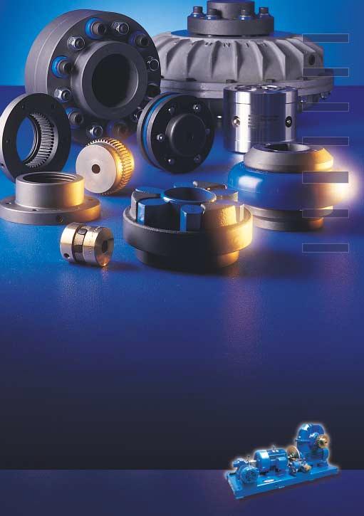
96
97 Notes RENOLD Hi-Tec Couplings. Tel: + 44 (0) Fax: + 44 (0) E-ail: sales@hitec.renold.com 97
98 Worldwide Sales and Services ARGENTINA Bennett Anderson, Gonzales Y Cia SA, J.Aguero 1817 (1605) unro Buenos Aires Tel: / 3531 Fax: Los Ases Ketten SA, Avda Gaona 4046, 1407 Buenos Aires Tel: Fax: AUSTRALIA Renold Australia Proprietary Ltd Wellington Road, ulgrave, Victoria 3170, ulgrave North Tel: +61 (0) Fax: +61 (0) Branch Tel: +61 (0) melcag@renold.com.au Unit 1, Victoria Street, Lidcombe, Sydney, NSW Tel: +61 (0) Fax: +61 (0) nswsales@renold.com.au Unit 10, 31 Boyland Avenue, Coopers Plains, Brisbane, Queensland Tel: +61 (0) Fax: +61 (0) Corner Orsmond & George Sts. Hindmarsh, Adelaide, South Australia Tel: +61 (0) Fax: +61 (0) Unit 2, 127 Grandstand Street, Belmont, Perth, West Australia Tel: +61 (0) Fax: +61 (0) Unit Industrial Drive, ayfield, NSW 2304 Tel: +61 (0) Fax: +61 (0) PO Box 159, Unanderra, Wollongong, NSW Tel: +61 (0) Fax: +61 (0) Shop B, 247 Ingham Road, Garbutt, Townsville, QLD Tel: +61 (0) Fax: +61 (0) AUSTRIA Renold GmbH Obere Donaustrasse 43, Postfach 60, A-1021 Wien. Tel: +43 (0) Fax: +43 (0) BANGLADESH Brady & Co (Bangladesh) Ltd, 31, Bangabandhu Avenue, Dhaka-1000 Tel: Fax: BELGIU Renold Continental Ltd Allée Verte 1,1000 Brussel. Tel: +32 (0) Fax: +32 (0) info@renold.be CANADA Renold Canada Ltd 121 Roy Boulevard, Brantford, Ontario, N3T 5N4 Toll Free: Tel: Fax: inquiry@renoldcanada.com 622 rue De Hull, Ville La Salle, Quebec, H8R 1V9. Toll Free: Tel: Fax: CHILE Sargent S.A., Avda. Presidente Bulnes No 205, Casilla 166-D, Santiago - Chile. Tel: (56 2) Fax: (56 2) secventas@sargentagricola.cl COLOBIA Transmission de Potencia SA Carrera 68B No10-98 Apartado Aereo 6794 Santafe de Bogato DC Tel: Fax: Importadora Casa Sueca Ltda., Calle 52, No. 1N-74, Apartado Aereo 1208, Cali. Tel: Fax: CZECH REPUBLIC Renold GesmbH Technical Office, Dipl. Ing. R. Badura, Jaroslavice 129, CZ Zlin. Tel: Fax: DENARK Renold A/S, Skelmarksvej 6, Postboks 90, 2605 Brøndby. Tel: Fax: renold@post9.tele.dk EGYPT Itaco, Int l for Trading & Agency, P.O. Box 7550, Nasr City, Cairo. Tel: Fax: EL SALVADOR VA & Cia Residencial San Luis, Avenida 4 #45 Block 2, San Salvador, El-Salvador, Central America Tel: FINLAND Kraftmek Oy, Hitsaajankatu 9, P.O. Box 36, FIN Helsinki Tel: Fax: FRANCE Renold Reducteurs, Zone Industrielle A, Rue de la Pointe, BP 359, Seclin Cedex. Tel: +33 (0) Fax: +33 (0) Renold Automotive (Chain only) Brampton Renold S/A, 188 Boulevard Lafayette BP 99, Calais Cedex Tel: +33 (0) Fax: +33 (0) GERANY Arnold & Stolzenberg, Postfach , Einbeck Juliusmühle Tel: +49 (0) Fax: +49 (0) GREECE Provatas Engineering 53/47 Dragatsaniou St, Piraeus. Tel: Fax HOLLAND Renold Continental Ltd, Jarmuiden 30c, 1046 AD Amsterdam. Tel: +31 (0) Fax: +31 (0) info@renold.nl HUNGARY Renold GesmbH Technical Office, Ing. Havasi Janos, Ret Utca 25, H-6200 Kiskörös. Tel: +36 (0) Fax: +36 (0) INDIA Voltas Limited., achine Tool Division, NK International House, 178 Backbay Reclamation, umbai, India. Tel: Fax: NORTHERN IRELAND Henry R. Ayton Ltd, Derriaghy, Dunmurry, Belfast. Tel: Fax: SOUTHERN IRELAND Henry R. Ayton Ltd., Broomhill Drive, Tallagh, Dublin 24 Tel: (0) Fax: (0) ISRAEL Technica J. Bokstein Co. Ltd, 3 Hatrupa Street, Netanya Tel: Fax: ITALY Bianchi Cuscinetti SpA Via Zuretti, 102, ilano, Tel: Fax: JAAICA asterton Ltd, Hanover Street, P.O. Box 73 Kingston. Tel: Fax: KOREA S.S. Corporation, Yeouido, P.O. Box 60, Seoul. Tel: Fax: ALAYSIA Renold (alaysia) SDN BHD, 39 Jalan TP 7/7, Sime UEP Industrial Park, Section 26, Shah Alam, Selangor. Tel: Fax: (General) Fax: (Sales) malaysia@renold.com 201, Jalan Simbang, Taman Perling, Joho Bharu, Johor, alaysia. Tel: + 60 (0) Fax: + 60 (0) malaysia@renold.com 452, Jalan Kuala Kangsar, Loke Lim Garden, Ipoh, Perak, alaysia. Tel: + 60 (0) Fax: + 60 (0) malaysia@renold.com 28B Jalan Perai Jaya 3, Bandar Perai Jaya,13600 Perai, Penang, alaysia Tel: Tel: Fax: malaysia@renold.com AURITIUS Dynamotors Ltd, P.O. Box 733, Bell Village, Tel: /8/9 Fax: EXICO Accessorios Automotrices y Rodamientos Industriales, S.A. de C.V., Calz Legaria 833-A Col Irigacion, exico DF Tel: Fax: NEW ZEALAND Renold New Zealand, 594 Rossbank Road, Avondale, Auckland. Postal Address: PO Box 19460, Avondale, Auckland. Tel: + 64 (0) Fax: + 64 (0) aksales@renold.co.nz Christchurch Branch Office, 32 Birmingham Drive, Christchurch, PO Box 9006, Christchurch, Tel: Fax: RENOLD Hi-Tec Couplings. Tel: + 44 (0) Fax: + 44 (0) E-ail: sales@hitec.renold.com 98
99 Worldwide Sales and Services NORWAY G. Heier A/S, Postal Address: Postboks 6615, Rodelokka, 0502 Oslo, Norway. Office Address: Thv, eyersgt. 7, Oslo. Tel: Fax: PAKISTAN Brady & Co. of Pakistan Ltd, Shernaz House, P.O. Box 4453, West Wharf Road, Karachi 2. Tel: / Fax: / PERU Corporacion Basco S.A.C. Av. Argentina 1165, Lima 1, RUC Tel: Fax: PORTUGAL Harker, Sumner & Cia Lda, 38 Rue De Cueta 48, P.O. Box 75, 4001-Oporto Codex. Tel: Fax: SINGAPORE Renold Transmission Limited 63 Hillview Avenue, #07-13, Lam Soon Industrial Building, Singapore Tel: Fax: renold@mbox5.singnet.com.sg SOUTH AFRICA Renold Croft (Pty) Limited, Corner Liverpool and Bolton Streets, Nestadt Industrial Sites, Benoni, 1501 Postal Address: Private Bag x 030, Benoni, Tel: + 27 (0) Fax: + 27 (0) renold@iafrica.com 89 Berea Road, Dalbridge, Durban, 4000, Postal Address: PO Box 18137, Dalbridge, Durban, Tel: + 27 (0) Fax: + 27 (0) Voortrekker Road, aitland, Cape Town, 7405 Postal Address: PO Box 211, aitland, Tel: + 27 (0) Fax: + 27 (0) Kempston Road, Port Elizabeth, Postal Address : PO Box 4080, Korsten, Tel: + 27 (0) Fax: + 27 (0) c van Bruggen St.Ext 25 Witbank, 1035, Postal Address: PO Box 2661, Witbank, Tel: + 27 (0) Fax: + 27 (0) acgra Industrial Park, Cnr. Alumina Allee & Bronze Bar, Altron, Richards Bay, 3900, Postal Address: PO Box 21247, Arboretum, Tel: + 27 (0) Fax: + 27 (0) SPAIN Brown Pestell, Ctra N-11 Lm Nave 5, Palleja, Barcelona. Tel: Fax: SWEDEN Renold Transmission AB, c/o omentum IS AB Hemvärnsgatan Solna Tel: + 46 (0) Fax: + 46 (0) info@renold.se SWITZERLAND Renold (Switzerland) Gmbh, Ringstrasse 16, Postfach 1115 CH-8600 Dübendorf 1. Tel: + 41 (0) Fax: + 41 (0) info@renold-gmbh.ch Route De Prilly 25, CH-1023 Crissier. Tel: + 41 (0) Fax: + 41 (0) crissier@renold-gmbh.ch THAILAND TES (Transmission Equipment Supply) Ltd 44/12 Ladprao 88 Road, Bangkapi, Bangkok Tel: Fax: TRINIDAD Tracmac Engineering Ltd, P.O. Box 945, Port of Spain, Trinidad, West Indies. Tel: Fax: TURKEY Glengo Ithalat lhracat umessillik AS, Gungoren Cad. No. 35 Bagcilar, Bakirkoy, Istanbul. Tel: Fax: UNITED KINGDO Renold Engineering Products Station Road, ilnrow, Rochdale OL16 3LS Tel: + 44 (0) Fax: + 44 (0) Web: Renold Gears Holroyd Gears Works, ilnrow, Rochdale OL16 3LS Tel: +44 (0) Fax: +44 (0) sales@gears.renold.com Web: Renold Clutches & Couplings Wentloog Corporate Park, Newlands Road, Cardiff CF3 2EU, Wales Tel: + 44 (0) Fax: + 44 (0) (Sales):+ 44 (0) couplings@cc.renold.com Web: Renold Hi-Tec Couplings 112 Parkinson Road Halifax HX1 3QH Tel: +44 (0) Fax: +44 (0) sales@hitec.renold.com Web: Holroyd Harbour Lane North, ilnrow, Rochdale, OL16 3LQ. Tel: +44 (0) Fax: +44 (0) info@holroyd.com Web: Renold Chain UK Sales, Horninglow Road, Burton upon Trent, Staffordshire, DE14 2PS. Tel: +44 (0) Fax: +44 (0) enquiry@renold.com USA Renold Power Transmission Corporation PO Box 46646, 8750 Global Way, West Chester, Ohio Tel: Fax: rptc@fuse.net Renold Inc Bourne Street, PO Box A, Westfield, New York, Tel: Fax: renold@cecomet.net VENEZUELA Equipos Y Acessorios Astral CA, Apartado 1651 Valencia. Tel: Fax: WEB Terms and Conditions In the interests of safety, customers are reminded that when purchasing any technical product for use at work (or otherwise), any additional or up-to-date information and guidance, which it has not been possible to include in the publication, should be obtained by you from your local sales office in relation to the suitability and the safe and proper use of the product. All relevant information and guidance must be passed on by you to the person engaged in, or likely to be affected by or responsible for the use of the product The performance levels and tolerances of our product stated in this catalogue (including without limitation, serviceability, wearlife, resistance to fatigue, corrosion protection) have been verified in a programme of testing and quality control in accordance with Renold, independent and/or international standard recommendations. No representations or warranties are given that our product shall meet the stated performance levels or tolerances for any given application outside the performance levels and tolerances for the product s own specific application and environment. Whilst all reasonable care in compiling the information contained in this catalogue is taken, no responsibility is accepted for errors. All information contained in this catalogue is subject to change without notice. The illustrations used in this catalogue represent the type of product described but the goods supplied may vary in some detail from those illustrated. The right is reserved to make modifications to the product to meet manufacturing conditions and/or developments (for example in design or materials). Product can be supplied by Renold companies or representatives around the world on the standard terms and conditions of sale of the company or representative from which the product is purchased. Copyright Renold Power Transmission Limited All rights reserved. Nothing contained in this publication shall constitute a part of any contract, express or implied. RENOLD Hi-Tec Couplings. Tel: + 44 (0) Fax: + 44 (0) E-ail: sales@hitec.renold.com 99
 13303484 Fax + 43 (0) 13303484-5 also at: Kiskörös (Hungary), Jaroslavice (Czech Republic). BELGIU Brussels.")
, Tel + 45 43 45 26 11 Fax + 45 43 45 65 92 FRANCE Seclin, Tel + 33 (0) 320 16 29 29 Fax + 33 (0) 320 16 29 00 Calais (Chain only), Tel + 33 (0) 321 97 99 45 Fax + 33 (0)")
100 RENOLD WORLDWIDE AUSTRALIA elbourne (Victoria), Tel + 61 (03) Fax + 61 (03) also at: Sydney, Brisbane, Adelaide, Perth, ayfield, Wollongong, Townsville. AUSTRIA Vienna, Tel + 43 (0) Fax + 43 (0) also at: Kiskörös (Hungary), Jaroslavice (Czech Republic). BELGIU Brussels. Tel + 32 (0) Fax + 32 (0) CANADA Brantford (Ontario), Tel Fax also at: ontreal. DENARK Bröndby (Copenhagen), Tel Fax FRANCE Seclin, Tel + 33 (0) Fax + 33 (0) Calais (Chain only), Tel + 33 (0) Fax + 33 (0) GERANY Einbeck, Tel + 49 (0) Fax + 49 (0) also at: Hamburg, Bielefeld, Düsseldorf, Frankfurt, Kornwestheim, Berlin. ALAYSIA Petaling Jaya, Tel Fax also at: Johor Bharu, Ipoh, Butterworth. NETHERLANDS Amsterdam, Tel Fax NEW ZEALAND Auckland, Tel Fax also at: Christchurch. SINGAPORE Singapore, Tel Fax SOUTH AFRICA Benoni, Tel Fax also at: Durban, Cape Town, Port Elizabeth, Witbank. SWEDEN Sollentuna (Stockholm), Tel + 46 (0) Fax + 46 (0) SWITZERLAND Dübendorf (Zürich), Tel Fax also at: Crissier (Lausanne). UK Renold Clutches & Couplings, Wales Tel + 44 (0) Fax + 44 (0) (Sales): +44 (0) couplings@cc.renold.com Renold Gears, Rochdale Tel + 44 (0) Fax + 44 (0) sales@gears.renold.com Renold Hydraulics & Variators, Bradford Tel + 44 (0) Fax + 44 (0) carter@renold.com Renold Hi-Tec Couplings, Halifax Tel + 44 (0) Fax + 44 (0) couplings@hitec.renold.com USA Chester, Ohio Tel Fax WEB E-AIL enquiry@renold.com For other country distributors please contact Renold UK. Whilst all reasonable care in compiling the information contained in this brochure is taken, no responsibility is accepted for printing errors. All information contained in this brochure is subject to change after the date of publication. Renold Power Transmission Ltd Ref: 2000 / ENG / 02.02
Couplings. Resilient and Soft Start Couplings. Superior Coupling Technology
 Couplings Resilient and Soft Start Couplings Superior Coupling Technology www.renold.com Clutches & Couplings Wentloog Corporate Park, Newlands Road, Cardiff CF3 2EU Wales Tel: +44 (0) 29 20792737 Fax:
Speed Reducers and Gearmotors
 and Gearmotors Table of Contents 1. General Information 2. How to Select...2.2 Configure a Model Number (Nomenclature)...2.4 AGMA Load Classifications...2.6...2.8 Single Reduction,,, Y3, Y5,...2.8 Single
Size 1120, Bore Ø0.75" Size 1320, Bore Ø1.25" Size 1420, Bore Ø1.375" 3/4HP. Size 1320, Bore Ø1.25" Size 1320, Bore Ø1.25" Size 1633, Bore Ø2.
 Product Range Hollow Shaft Type Selections shaded in blue offer an increased service factor. Please refer to the gearmotor selection tables for specific unit service factor details. Nominal Ratio (:1)
Series C Helical Worm
 Series C Helical Worm Technical p to - 45 Kw / 10,000 Nm Geared otors CC-2.01GB0914 PRODCTS IN THE RANGE Series A Worm Gear units and geared motors in single & double reduction types Series BD Screwjack
Couplings. Resilient and Soft Start Couplings. 7th Edition
 Couplings Resilient and oft tart Couplings 7th Edition Clutches & Couplings Wentloog Corporate Park, Newlands Road, Cardiff CF3 2EU Wales Tel: +44 (0) 29 20792737 Fax: +44 (0) 29 20793004 (ales): +44 (0)
Power Transmission Products. Maurey Couplings. Hi-Flex Tire Couplings Hi-Q Jaw Couplings Finished Bore Sleeve Couplings Rigid Bushed Sleeve Couplings
 Power Transmission Products Maurey Couplings Hi-Flex Tire Couplings Hi-Q Jaw Couplings Finished Bore Sleeve Couplings Rigid Bushed Sleeve Couplings Hi-Q Flexible Couplings R to enable full power transmission
Series P Planetary. Technical Up to - 90kW / 65000Nm. Planetary CP-2.00GB0 1
 VARIMAX AG, Antriebstechnik, Normannenstrasse 14, Postfach 762, CH-3018 Bern Tel. +41 (0)31 990 00 70 e-mail info@varimax.ch Fax +41 (0)31 990 00 71 web www.varimax.ch Series P Planetary Technical Up to
Series F Shaft Mounted Helical
 Series F Shaft ounted Helical Technical Up to - 110 kw / 16,500 Nm Geared otors CF-2.01GB1 ATEX Compliance Assured Total compliance with the ATEX Directive safeguarding the use of industrial equipment
Gear Coupling. Applications
 Gear Coupling Applications Power Transformation Print & Paper Industries Gear Boxes Textile Industries Conveyors Pumps Compressors Process, Chemical & Pharmaceutical Industries Nylon Gear Couplings Nylon
SPIDERFLEX SPIDERJAW/WRAP PINFLEX CROWNPIN TYREFLEX DISCFLEX CHAINFLEX RBI GEARFLEX HYDRASTART FREEWHEELS. Industrial Couplings & Freewheel Clutches
 SPIDERFLEX SPIDERJAW/WRAP PINFLEX CROWNPIN TYREFLEX DISCFLEX CHAINFLEX RBI GEARFLEX HYDRASTART FREEWHEELS Industrial Couplings & Freewheel Clutches Couplings Crownpin Heavy duty pin and buffer 249 kn.m
Tyreflex Couplings.
 Tyreflex Couplings trength through ervice Renold Gears has been manufacturing high quality, high specification gear units for over 100 years and has always been at the leading edge of gear technology with
Cyclo Speed Reducers CATALOG
 Cyclo 6000 CATALOG 03.601.50.005 Cyclo 6000 Superior design, powerful performance The Cyclo 6000 is also available as an inline Gearmotor To request a catalog, or for more information on any of our high
Catalog April Metric Motorized Torque-Arm II Technical catalog
 Catalog April 2015 Metric Motorized Torque-Arm II Technical catalog With expertise, and a comprehensive portfolio of products and life-cycle services, we help value-minded industrial customers improve
CYCLO 6000 Gearmotors. How to Select. How to. Select. Cyclo 6000 Series. How to Select 2.1
 2 How to Select How to Select Cyclo 6000 Series How to Select 2.1 How to Select a Gearmotor Step 1: Step 2: Collect data about your application Before starting you need to know the: (e.g. Conveyor, Mixer,
Specialty Couplings. Overview. Deltaflex Coupling Design Lovejoy offers maximum misalignment capacity with the Deltaflex coupling! SP-3.
 Overview Deltaflex Coupling Design Lovejoy offers maximum misalignment capacity with the Deltaflex coupling! The Deltaflex coupling is the real solution to installation, misalignment, and performance problems.
Couplings. Resilient and Soft Start Couplings.
 Couplings Resilient and oft tart Couplings Page 01 Contents Page No Renold Gears 02 Renold Couplings 03 Typical Applications 04 The Renold Collection 06 Coupling Comparison Chart 08 Coupling election
Universal Joints. In This Section: D Type HD Type D Type Stainless NB (Needle Bearing) Type LOJ Type DD and DDX Type Universal Joint Boots
 Type LOJ Type DD and DDX Type Universal Joint Boots") JW Universal Joints In This Section: D Type HD Type D Type Stainless NB (Needle Bearing) Type LOJ Type DD and DDX Type Universal Joint Boots www.lovejoy-inc.com 329-1 JW Universal Joints Safety Warning
JW Universal Joints In This Section: D Type HD Type D Type Stainless NB (Needle Bearing) Type LOJ Type DD and DDX Type Universal Joint Boots www.lovejoy-inc.com 329-1 JW Universal Joints Safety Warning
Hyponic. Hypoid Right Angle Gearmotor and Reducer CATALOG
 Hypoid Right Angle Gearmotor and Reducer CATALOG 12.001.50.005 Hypoid Right Angle Patented, High-Performance Gearmotors and Reducers Featuring All-Steel Hypoid Gearing U. S. PAT. NO. 5,203,231; U.S. PAT.
Speed Reducers. Speed Reducers. Speed Reducers. How to. Select. Cyclo HBB. Speed Reducers 2.1
 2 How to Select 2.1 How to select a Reducer Step 1: Step 2: Step 3: Collect data about your application Before starting you need to know the: Application (e.g. Conveyor, Mixer, etc.) Hours of Operation
General Description 2. Unit Designations 3. Explanation and use of Ratings and Service Factors 4. Load Classification by Applications 5
 CONTENTS General Description 2 nit Designations 3 Explanation and use of Ratings and Service Factors 4 Load Classification by Applications 5 Selection Procedure 6-7 Options 8-9 otor Adaptors 10-12 Lubrication
CONTENTS MAXUM Concentric Reducers
 CONTENTS s Features/Benefits.............................................. G3-2 Specifications................................................. G3-4 How to Order.................................................
FLEXIBLE JAW COUPLINGS
 To order this part, call Lifco Hydraulics USA Toll Free at -800-92-849 Jaw Type Couplings USA Standard The Jaw Type Couplings from Vescor are offered in the industry s largest variety of stock bore/keyway
Flange Flexible Couplings.
 Flange Flexible Couplings Coupling Selection Coupling Selection How to Select Standard Selection The Standard Selection may be used for engine driven, motor, or turbine applications. The following information
RXC. traction drives. When an ordinary drive falls short... Featuring an all metal power train and optional advanced electronic control capabilities
 RXC traction drives Featuring an all metal power train and optional advanced electronic control capabilities When an ordinary drive falls short... Ring Cone Adjustable Speed Traction Drives Control Ring
Speed Reducers and Gearmotors featuring Keyless Taper-Grip Bushing
 Cyclo BBB BEVEL BUDDYBOX Speed Reducers and Gearmotors featuring Keyless Taper-Grip Bushing CATALOG 13.601.50.006 Cyclo BBB Bevel Buddybox Rugged Spiral Bevel Output Modular Cyclo Input Compact Size Ring
Catalog. MagnaGear XTR gear reducers Gearing
 Catalog MagnaGear XTR gear reducers Gearing We provide motors, generators and mechanical power transmission products, services and expertise to improve customers' processes and optimize the total cost
SURE-FLEX ELASTOMERIC COUPLINGS
 SECTION F1 SURE-FLEX ELASTOMERIC COUPLINGS Need No Lubrication, No Maintenance Quick, Easy Installation Clean, Quiet Performance TB WOOD S INCORPORATED Chambersburg, Pennsylvania 17201 T.B. WOOD S CANADA
Maxum XTR Concentric reducers catalog
 MECHANICAL POWER TRANSMISSION Maxum XTR Concentric reducers catalog Maxum XTR Concentric reducers catalog To receive a copy of the Dodge Maxum XTR Catalog, Dodge Bearing Engineering Catalog, Dodge Gearing
LMI Product Catalog. Premium Shaft Mount Gear Reducers Built For The Long Haul
 LMI Product Catalog Premium Shaft Mount Gear Reducers Built For The Long Haul Featuring Shaft Mount Models DIR1 through DIR10, Accessories, and Rebuild Kits The Better Alternative! January 2004 LMI Shaft
Hyponic. Hypoid Right Angle Gearmotor and Reducer CATALOG
 Hypoid Right Angle Gearmotor and Reducer CATALOG 12.001.50.007 Hypoid Right Angle Patented, High-Performance Gearmotors and Reducers Featuring All-Steel Hypoid Gearing U. S. PAT. NO. 5,203,231; U.S. PAT.
SURE-FLEX ELASTOMERIC COUPLINGS
 SECTION F1 SURE-FLEX ELASTOMERIC COUPLINGS Need No Lubrication, No Maintenance Quick, Easy Installation Clean, Quiet Performance TB WOOD S INCORPORATED Chambersburg, Pennsylvania 17201 T.B. WOOD S CANADA
SPECIFICATION HOW TO ORDER QUANTIS QUANTIS
 The DODGE speed reducer is suitable for c-face, separate, or integral gearmotor construction in either foot or output flange mountings, and available in single, double or triple ratios. The DODGE RHB and
Mechanical. Flexible Couplings. Lowest Cost TOTAL Solution
 Mechanical FC Flexible Couplings Lowest Cost TOTAL Solution SECTION F1 SURE-FLEX ELASTOMERIC COUPLINGS Need No Lubrication, No Maintenance Quick, Easy Installation Clean, Quiet Performance TB WOOD S INCORPORATED
Thomas Flexible Disc Couplings (Inch)
") Disc Catalog Download the most up-to-date version at www.rexnord.com/documentation Thomas Flexible Disc s (Inch) Table Of Contents DESCRIPTION PAGE Application Guide................................................................................................................
Disc Catalog Download the most up-to-date version at www.rexnord.com/documentation Thomas Flexible Disc s (Inch) Table Of Contents DESCRIPTION PAGE Application Guide................................................................................................................
(d) Bore Size Check from Dimensions table (page 112) that chosen flanges can accommodate required bores.
 Bore Size Check from Dimensions table (page 112) that chosen flanges can accommodate required bores.") Fenaflex Couplings The Fenaflex coupling is a highly flexible, torsionally elastic coupling offering versatility to designers and engineers with a choice of flange combinations to suit most applications.
Fenaflex Couplings The Fenaflex coupling is a highly flexible, torsionally elastic coupling offering versatility to designers and engineers with a choice of flange combinations to suit most applications.
Falk Type YB & GHB Horizontal Right Angle Gear Drives
 Falk Series YB & GHB Gear Drives Proven Performance for Thermal Capacity Applications (English Inch) Falk Type YB & GHB Horizontal Right Angle Gear Drives Since 1897, Falk gear drives have benefitted from
Falk Ultramite UC Helical Concentric Gear Drives
 Gear Catalog Download the most up-to-date versions at www.rexnord.com Falk Ultramite UC Helical Concentric Gear s (Inch) Falk Ultramite UC Helical Concentric Gear To learn more about the Falk Ultramite
Thomas Flexible Disc Couplings (Metric)
") Disc Catalog Download most up-to-date versions at www.rexnord.com Thomas Flexible Disc s (Metric) Table Of Contents DESCRIPTION PAGE Application Guide................................................................................................................
Disc Catalog Download most up-to-date versions at www.rexnord.com Thomas Flexible Disc s (Metric) Table Of Contents DESCRIPTION PAGE Application Guide................................................................................................................
Cyclo BBBBEVEL BUDDYBOX
 Cyclo BBBBEVEL BUDDYBOX Speed Reducers and Gearmotors featuring Keyless Taper-Grip Bushing CATALOG 13.601.50.003 Cyclo BBB BEVEL BUDDYBOX Speed Reducers and Gearmotors featuring Keyless Taper-Grip Bushing
Jaw Type JW JW-1. Polígono Indutrial O Rebullón s/n Mos - España -
 -1 Overview Couplings USA Standard Elastomer-in-Compression The couplings from Lovejoy are offered in the industry s largest variety of stock bore/keyway combinations. These couplings require no lubrication
Jaw Type. Overview. Jaw Type Couplings USA Standard Elastomer-in-Compression
 -1 Overview Jaw Type Couplings USA Standard Elastomer-in-Compression The Jaw Type couplings from Lovejoy are offered in the industry s largest variety of stock bore/keyway combinations. These couplings
L-Jaw Elastomeric Couplings
 L-Jaw Elastomeric Couplings F3 100% interchangeable with industry standard 3 Insert materials available 3 Hub materials available Large selection of sizes P-1686-TBW 4/16... TB Wood s 888-829-6637 F3-1
Thomas Flexible Disc Couplings (Metric)
") Disc Catalog Download the most up-to-date version at www.rexnord.com/documentation Thomas Flexible Disc s (Metric) Table Of Contents DESCRIPTION PAGE Application Guide................................................................................................................
Disc Catalog Download the most up-to-date version at www.rexnord.com/documentation Thomas Flexible Disc s (Metric) Table Of Contents DESCRIPTION PAGE Application Guide................................................................................................................
Crownpin Couplings.
 Crownpin Couplings trength through ervice Renold Gears has been manufacturing high quality, high specification gear units for over 100 years and has always been at the leading edge of gear technology with
Falk Series Y & YF Gear Drives. Proven Performance for High Thermal Capacity Applications (English Inch)
") Falk Series Y & YF Gear Drives Proven Performance for High Thermal Capacity Applications (English Inch) Falk Series Y&YFParallel Gear Drives Since 1897, Falk gear drives have benefitted from specialized
Falk Series Y & YF Gear Drives Proven Performance for High Thermal Capacity Applications (English Inch) Falk Series Y&YFParallel Gear Drives Since 1897, Falk gear drives have benefitted from specialized
Jaw. In This Section:
 Jaw In This Section: L Type LC Type Al Type - Aluminum SS Type - Stainless RRS and RRSC Types - Spacer C and H Type - Medium / Heavy Duty RRC Type - Spacer www.lovejoy-inc.com 13-1 Jaw Safety Warning When
XL Right Angle and Parallel Reducers and Gearmotors
 CONTENTS XL Right Angle and Parallel Reducers and Gearmotors Contents Updated 11-7-2016 Features / Benefits XL Right Angle Reducers and Gearmotors...XL-2 XL Parallel Reducers and Gearmotors...XL-3 Specification
PRODUCT MANUAL TYRE-FLEX COUPLING (T,TO & RST)
") RATHI TRANSPOWER PVT. LTD. PUNE - INDIA PRODUCT MANUAL TYRE-FLEX COUPLING (T,TO & RST) R-PM-T-1/3-1/14 Page 1 INDEX CONTENTS PAGE Standard Features 3 At a Glance 3 TYRE-FLEX Family 3 Elastomer Information
RATHI TRANSPOWER PVT. LTD. PUNE - INDIA PRODUCT MANUAL TYRE-FLEX COUPLING (T,TO & RST) R-PM-T-1/3-1/14 Page 1 INDEX CONTENTS PAGE Standard Features 3 At a Glance 3 TYRE-FLEX Family 3 Elastomer Information
POWER TRANSMISSION FLEXIBLE COUPLINGS FLEX FLEX
 POWER TRANIION IBLE COUPLIN 2 IBLE COUPLIN IBLE COUPLIN The Flex coupling combines all the advantages which can be expected of an ideal flexible coupling. It is a torsional flexible coupling which offers
Sure-Flex Plus couplings are selected as component parts. 1. Determine SLEEVE material and type. Refer to pages 4 & 5
 Sure-Flex Plus 4-Way flexing action absorbs all types of shock, vibration and misalignment Torsional Sure-Flex Plus coupling sleeves have an exceptional ability to absorb torsional shock and dampen torsional
POWER TRANSMISSION FLEXIBLE COUPLINGS HADEFLEX X / TX / F HADEFLEX
 POWER TRANIION FLEXIBLE COUPLIN X / TX / F 2 FLEXIBLE COUPLIN The flexible Hadeflex couplings are claw couplings with a flexible element to provide a torsionally flexible connection for shafts. The flexible
Unique Tyre Type Flexible Cushion Couplings
 Unique Tyre Type lexible Cushion Couplings Highly flexible & resilient Absorbs arge isalignment ow Torsional Stiffness Dampens shock & Vibration lexible element easily replaceable insitu Ideally suitable
QUADRA-FLEX 4-Way Flexing
 QUADRA-FLEX 4-Way Flexing Quadra-flex FLEXIBLE COUPLINGS Stocked Nationwide In Sizes 3 Through 16 Styles J, S, B, and SC Spacers C-4 QUADRA-FLEX 4-Way Flexing Martin QUADRA-FLEX Couplings, Non Lubricated,
MASTER ENGINEERING/ TECHNICAL. XL Reducers And Gearmotors INSTALLATION
 INSTALLATION Proper installation of MASTER speed reducers will ensure reliable service and maximum life. Key items to minimize possible failures include: Gear Case Mounting To insure uniform pressure mount
Tyreflex Couplings.
 Tyreflex Couplings trength through ervice Renold Gears has been manufacturing high quality, high specification gear units for over 100 years and has always been at the leading edge of gear technology with
Section 9: Gearboxes: Series K
 GEARBOXES Section : 9 Section 9: Gearboxes: Series K The Fenner Series K incorporates all the core design features in a highly efficient yet flexible bevel helical drive. Drives up to 90 Highly efficient
Eflex and Powerpin Flexible Couplings
 Eflex and Powerpin Flexible s Accepts parallel, angular and axial misalignment Torsionally flexible Simple assembly Wide range of standard designs No lubrication 80 or 90 shore hardness close fitting elements
A L T R A I N D U S T R I A L M O T I O N Flexible Couplings
 A L T R A I N D U S T R I A L M O T I O N Flexible Couplings SECTION F1 SURE-FLEX ELASTOMERIC COUPLINGS Need No Lubrication, No Maintenance Quick, Easy Installation Clean, Quiet Performance TB WOOD S
M.H INDUSTRIAL EQUIPMENTS
 M.H INDUSTRIAL EQUIPMENTS Tyre Flexible Cushion Coupling Highly flexible & resilient Absorbs Large Misalignment Low Torsional Stiffness Dampens shock & Vibration Flexible element easily replaceable insitu
A SERIES ELASTOMER COUPLINGS
 A Retaining ring with locking feature B Wrap-around elastomeric insert C Hubs (blank or bored) D Anti-corrosion treatment A B C C D Spacer Arrangement Shown Product Description A Series elastomer couplings
Series 54 and S54 Resilient Couplings
 Series 54 and S54 Resilient s Bibby Transmissions Resilient s Bibby are the world originator of the resilient grid type shaft coupling, which is universally accepted by engineers to be one of the most
Disclosure to Promote the Right To Information
 इ टरन ट म नक Disclosure to Promote the Right To Information Whereas the Parliament of India has set out to provide a practical regime of right to information for citizens to secure access to information
Series F Shaft Mounted Helical
 Series F Shaft ounted elical Technical p to - 150 P / 146,000 lb.in Geared otors CF- S 11 PRODCTS IN TE RANGE Serving an entire spectrum of mechanical drive applications from food, energy, mining and metal;
Section 9: Gearboxes: Series F
 GEARBOXES Section 9: Gearboxes: Series F The new Fenner Series F geared motor range is primarily designed as a compact shaft mounted unit incorporating an integral torque reaction bracket. ew range now
FALK ULTRAMITE Delivers Local Availability, NEMA/IEC Compatibility Plus Drop-in Replacement
 Falk Ultramite UB Right-Angle Gear Drive Delivering The Right Punch for Productivity (English-Inch) FALK ULTRAMITE Delivers Local Availability, NEMA/IEC Compatibility Plus Drop-in Replacement It s a winning
PRODUCT MANUAL B-FLEX COUPLING
 RATHI TRANSPOWER PVT. LTD. PUNE - INDIA PRODUCT MANUAL B-FLEX COUPLING R-PM-B-01/02-01/14 Page 1 INDEX CONTENTS PAGE Features of B-FLEX Coupling 3 At a glance 3 Components of B-FLEX Coupling 3 How B-FLEX
Discflex Couplings.
 Discflex Couplings trength through ervice Renold Gears has been manufacturing high quality, high specification gear units for over 100 years and has always been at the leading edge of gear technology with
S-Flex. Overview. Elastomer in Shear Type Couplings
 -1 Elastomer in Shear Type Couplings Protection from misalignment, shock, and vibration: Overview The simple design of the S Flex coupling ensures ease of assembly and reliable performance. No special
V ariodrive units are available with standard NEMA motor flange as well as optional IEC motor flanges to fit your needs.
 Features and Benefits Ribbed aluminum housing* provides expanded surface area and greater heat dissipation than traditional cast iron housings. This allows for higher thermal capacity and reduced internal
U-DISC 6-BOLT UNITIZED SPACER DISC COUPLING
 U-DISC 6-BOLT UNITIZED SPACER DISC COUPLING THE U-DISC 6-BOLT UNITIZED SPACER DISC COUPLING Same Day Shipping Stocked in Two Convenient Locations Simple 3-Piece Spacer Disc Coupling Factory Pre-Assembled
INDEX SECTION : M GRID COUPLING SECTION : N GEAR COUPLING SECTION :OJAWCOUPLING
 INDEX PAGE # SECTION : M GRID COUPLING GRID COUPLING Selection Procedure M 1 Coupling Selection based on Equivalent hp Ratings M 2-3 Service Factor M 4 Grid Coupling Type T-10 M 5 Grid Coupling Type T-20
HELICAL AND BEVEL-HELICAL UNITS
 I V-I IS S I W I QS I IS ISI V-I IS ISI II SII, KY SYS IIY I SVI SSIII IY SI S I SIS I SIS I SIS I SIS /V V-I SIS /V V-I SIS /V V-I SIS SIS /V SIS SIS SIS SIS SIS SIS V SIS SIS V SIS SIS V SIS S S I SIIS
QUADRA-FLEX. Quadra-Flex FLEXIBLE COUPLINGS. Stocked Nationwide In Sizes 3 Through 16. Styles J, S, B, and SC Spacers C-4
 QUADRA-FLEX 4-Way Flexing Quadra-Flex FLEXIBLE Stocked Nationwide In Sizes Through 6 Styles J, S, B, and SC Spacers C-4 QUADRA-FLEX 4-Way Flexing Martin QUADRA-FLEX Couplings, Non Lubricated, Maintenance
METALDRIVE Disc Couplings
 ETADRIVE Disc Couplings ETADRIVE ETADRIVE disc couplings ETADRIVE couplings are fully made of steel and are used in all applications where high reliability, precision, and no maintenance are required.
Jaw. In This Section:
 Jaw In This Section: L Type LC Type Al Type - Aluminum SS Type - Stainless RRS and RRSC Types - Spacer C and H Type - Medium / Heavy Duty RRC Type - Spacer www.lovejoy-inc.com 13-1 Jaw Safety Warning When
TW Series Heavy Duty Worm Gear Units
 TW eries eavy Duty Worm Gear Units uperior Gear Technology TW eries - Product Features Wide range of gear unit type single and double reduction options for complete design flexibility. Unique olroyd tooth
Hydrastart Couplings.
 ydrastart Couplings trength through ervice Renold Gears has been manufacturing high quality, high specification gear units for over 100 years and has always been at the leading edge of gear technology
SHAFT MOUNTED HELICAL GEAR REDUCER
 Shaft Mounted Helical Gear Assembly INTRODUCTION The VIGNESSH Shaft Mounted Helical Gear Units are the result of experience in design and production, taking advantage of the most recent relevent research
DRIVE COUPLINGS DRIVE COUPLINGS
 DRIVE COUPLINGS Fenner shaft couplings range from highly resilient to totally rigid and are all precision manufactured using high quality ferrous materials and the latest polymer technology. Fenaflex tyre
Shaft Mounted Speed Reducer. Technical Catalogue
 Shaft Mounted Speed Reducer Technical Catalogue Where others fit, We perform Contents The Challenge SMSR stands tall amongst the crowd. Packed full of attention to detail, the Challenge SMSR delivers performance
Series F Shaft Mounted Geared Motor- Version 3
 Series F Shaft ounted Geared otor- Version 3 Technical p to - 45kW/ 8000 Nm Geared otor CF3.01-GBD-0 18 PRODCTS IN TE RANGE Series A Worm Gear units and geared motors in single & double reduction types
FALK ULTRAMITE Delivers Local Availability, NEMA/IEC Compatibility Plus Drop-in Replacement
 Falk Ultramite UJ Shaft-Mounted Offset Helical Gear Drive Delivering The Right Punch for Productivity (English-Inch) FALK ULTRAMITE Delivers Local Availability, NEMA/IEC Compatibility Plus Drop-in Replacement
METALDRIVE Disc couplings
 ETADRIVE Disc couplings ETADRIVE couplings are fully made of steel and are used in all applications where high reliability, precision and no maintenance are required. Features All steel made Superior disc
HELIMAX. Parallel/Orthogonal Gear Units with Ground Helical Gear. Bipartite housing. Monobloc housing. 1 Stage
 HELIAX Parallel/Orthogonal Gear Units with Ground Helical Gear Bipartite housing onobloc housing 1 Stage www.wegcestari.com Index Description Page General characteristics 2 Product designation 3-5 Selection
Flexible Jaw Couplings
 Flexible Jaw Martin Offers The Martin Universal Completely Interchangeable No Lubrication asy Installation No Metal to Metal Contact asy inspection of load carrying Spider Flexibility of angular or parallel
Section 9: Gearboxes: Series W
 GEARBOXES Section : 9 Section 9: Gearboxes: Series W A modular designed aluminium worm box available in a vast range of sizes and ratios for cost effective solutions. 9 s with ratings from 0.09 to 7.5kW
Falk Steelflex Grid Couplings (Metric)
") Grid Coupling Catalog Download the most up-to-date versions at www.rexnord.com Falk Steelflex Grid Couplings (Metric) Table Of Contents DESCRIPTION PAGE Falk Steelflex Grid Coupling Application Guide...3
Grid Coupling Catalog Download the most up-to-date versions at www.rexnord.com Falk Steelflex Grid Couplings (Metric) Table Of Contents DESCRIPTION PAGE Falk Steelflex Grid Coupling Application Guide...3
POWER TRANSMISSION RIGID COUPLINGS
 POWER TRANIION RIID COUPLIN C C-ECO C 2 EAR COUPLIN C / C-ECO RIID COUPLIN C ear couplings C are flexible shaft connections suitable for a positive torque transmission. They ensure to compensate radial,
Advantages of Delroyd Worm Gearing
 Advantages of Delroyd Worm Gearing Compactness and High Ratio Reduction Single reduction worm gearing offers high ratio reduction with few moving parts in a close-coupled compact drive. The right angle
Freewheels Sprag and Trapped Roller Clutches
 Freewheels Sprag and Trapped Roller Clutches Overrunning Indexing Backstopping Superior Freewheel Technology Strength through Service Renold Gears has been manufacturing high quality, high specification
Description. General characteristics 2. Product Code 3-5. Selection of gear-unit 6-7. Service factors 8-9
 www.wegcestari.com Index Description Page General characteristics 2 Product Code 3-5 Selection of gear-unit 6-7 Service factors 8-9 Radial forces / Permissible Radial orce -12 Output- torque 13 echanical
COUPLINGS HRC FLEXIBLE COUPLINGS CHAIN SHAFT COUPLINGS SPLINE CLUTCHES TORQUE LIMITERS TORQUE LIMITER COUPLINGS
 COUPLINGS HRC FLEXIBLE COUPLINGS CHAIN SHAFT COUPLINGS SPLINE CLUTCHES TORQUE LIMITERS TORQUE LIMITER COUPLINGS FLEXIBLE COUPLINGS HRC TYPE Hercus HRC Couplings are designed for general-purpose applications
Gearbox standard series Your industrial Gearboxes. Standard Industrial NH/NHK
 www.gamesagearbox.com Standard Industrial 1 Contents Gear Design and Construction 3 Service Factors 5 Example of Selection 7 Spur Gearboxes NH I 8 NH II, NHS II, NHZ I2 NH III, NHS III, NHZ II7 NH IV,
METALDRIVE Disc Couplings METALDRIVE
 ETADRIVE Disc Couplings ETADRIVE Contents ETADRIVE Disc Couplings age Features 83 ETADRIVE disc coupling executions 84 Technical characteristics 85 GD type S 86 GD type DC 87 GD type SA1 - SA2 88 GD type
A L T R A I N D U S T R I A L M O T I O N. Flexible Couplings
 A L T R A I N D U S T R I A L M O T I O N Flexible Couplings DURA-FLEX METRIC COUPLINGS Patent No. 5,611,732 FEATURES Metric Hardware Designed from the ground up using finite element analysis to maximize
Clutch Couplings FW/FWW. Overrunning Ball Bearing Supported, Sprag Clutch Couplings. FW Series. FWW Series. Typical Applications
 s Overrunning Ball Bearing Supported, Sprag s Series For in-line shaft applications Outer race overrunning intermediate speed Inner race overrunning high speed clutch couplings are comprised of an FSO
4 Fenner Torque Drive Plus 3
 Fenner Torque Drive Plus 3 offers; State of the art power ratings. Compact drive package - reduced weight. Quiet operation. Accuracy of positioning. Anti-static as standard. Runs on standard HTD pulleys.
RESILIENT COUPLINGS. Non-Lubricated - Maintenance-Free - High Torque Capacity - Absorbs Shock Loads
 RESILIENT COUPLINGS Non-Lubricated - Maintenance-Free - High Torque Capacity - Absorbs Shock Loads MAX-C K MAX-C MAX-C UB MAX-C K and UB are typically used on: Overhead cranes Runout/entry/exit tables
The Strong Silent Type
 The Strong Silent Type Shaft Mount Speed Reducers SMR-15 Vortex Shaft Mount Reducers Engineering Guide VORTEX www.vortexreducer.com 2 Shaft Mount Speed Reducers What do you want to do? Understand an Engineering
INDEX 1.0 GENERAL INFORMATION 3.0 ELECTRIC MOTORS 2.0 SHAFT MOUNTED GEARMOTORS 2.11 GEARMOTOR RATING CHARTS SPEED REDUCERS RATING CHARTS...
 INDEX 1.0 GENERAL INFORMATION 2.11 GEARMOTOR RATING CHARTS 25 2.12 SPEED REDUCERS RATING CHARTS... 64 2.13 MOTOR AVAILABILITY... 84 2.14 MASS MOMENT OF INERTIA... 88 1.1 SYMBOLS AND UNITS... 2 1.2 TORQUE...