AP312HP Gear Pumps. Single and multiple cast iron gear pumps. Reference: 200-P EN-01 1/54. Issue:
|
|
|
- Leona Arnold
- 6 years ago
- Views:
Transcription


1 Gear Pumps Single and multiple cast iron gear pumps Reference: 200-P EN-01 Issue: /54
2 Contents Page 1 General information External gear pumps components and construction / benefits Technical data Pressure Suction General precaution Identifying the rotation direction Formulas to determinate main gear pump operate parameters Overview standard pump configurations Standard components configuration Single pump customised versions Single pump customised versions order example Shaft end code Front cover/mounting flange Single pump dimensions Multiple gear pumps Multiple gear pumps: + standard cast iron versions Multiple gear pumps: +AP212HP standard cast iron versions Multiple gear pumps: +AP212 cast iron + aluminium versions Multiple gear pumps: ++AP212HP cast iron versions Multiple gear pumps: ++AP212 cast iron + aluminium versions Product identification plate Application form /54
 and several combinations of double pumps, triple pumps, and so on, that can be assembled together according to versions of displacement, flanging, and auxiliary valves.")

 cast iron pump and motor series, ucher Hydraulics has completed its product range introducing the new cast iron pump group 3.")

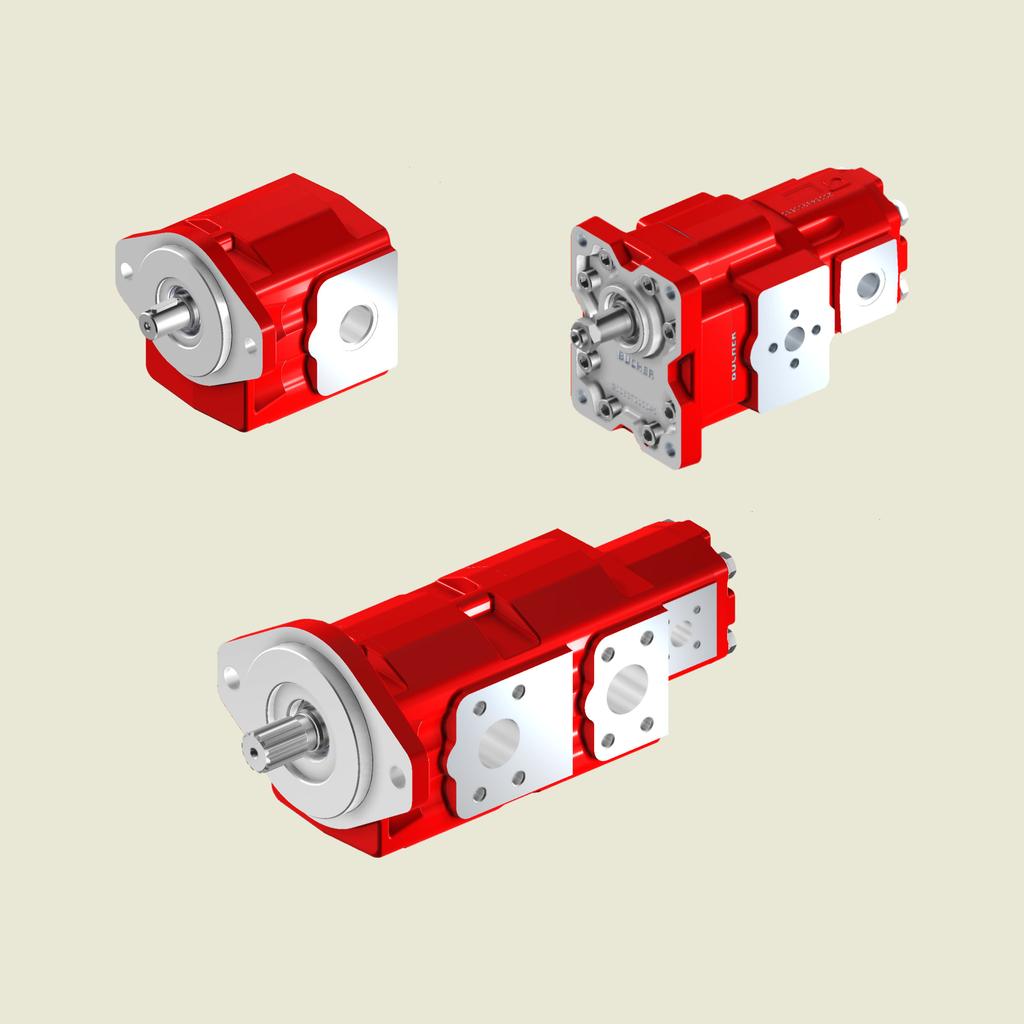
3 1 General information The product range of ucher Hydraulics SpA includes single pumps HP-250HP HP (corresponding with the common group denominations: ) and several combinations of double pumps, triple pumps, and so on, that can be assembled together according to versions of displacement, flanging, and auxiliary valves. ucher Hydraulics SpA has supplied a wide range of external gear pumps and motors to industrial and mobile applications since many years. ucher s external gear pumps are widely used in modern hydraulic system to obtain high performances, long life service and low purchase and maintenance costs. Thanks to the positive field experiences recorded on the group 2 (AP212HP) and group 2.5 (AP250HP) cast iron pump and motor series, ucher Hydraulics has completed its product range introducing the new cast iron pump group 3. The new pump has been developed with modern and robust design concepts. Strong 2 pieces structure, big shafts diameter as well as high quality materials, allows to the to reach very high quality and performance levels, in order to fulfill the most innovative types of machines and applications. ucher designed this new pump with support bearings mounted in the cast iron body and covers. Tandem and triple pumps are also available with direct connections between the shafts. is specifically developed for wheel loaders, excavators and telehandlers applications. ucher Hydraulics has so achieved this state of the art by constantly improving its design, control and manufacturing techniques aligned with the latest technological developments, while simultaneously enhancing its Quality System ensuring that every single product offers the same high standards. Main applications and benefits Wheel loader Excavator Telehandler Robust design in compact dimensions Teeth design optimisation oriented to reduce pressure pulsation Reduced noise and vibration Reduced number of components - reduced weight ouble shaft seals - More shaft protection and long life without external leakage HNR seals Wide fluid temperature range admitted High volumetric and mechanical efficiencies Single or multistage possible configurations Strong splined shaft multistage connections AP212 aluminium / AP212HP cast iron rear interface ucher validation method: long life expectancy. 3/54
4 1.1 External gear pumps components and construction / benefits A C E F G F E A Cast iron front cover: the standard front cover design can be fitted to two different pump interfaces Cast iron main pump body: wide range of displacements obtainable with two different basic bodies both with back cover integrated. Rear ports on request. C HNR seal material instead of NR ouble HNR shaft seals E Strong pressure balance plate instead of aluminium. alancing area and intermediate notches optimised ENEFITS F Large diameter bearings, fitted both in front cover and body G Large number of teeth, tooth profile optimised, larger shaft diameter A Flexibility/smaller number of components A Reduced risk of external leakage A E High efficiencies/pressure limits A E Long life expectancy C Wider temperature range E E G G Lower pressure ripple Noise/vibration reduction E F G Higher load capacity and transmissible torque E F G Low friction and high mechanical efficiency E F G Higher max. pressure limit. The front mounting flange and the body/backcover are made of high strength cast iron to gives thermal stability, resistance to contamination and the strength necessary for persistently high levels of performance and life, needed in demanding heavy duty applications. ody/back cover integrated, larger shaft diameter, large-diameter bearing and bronze trust plate have been optimized to provide heavy duty, high pressure limits, high efficiencies and long life expectancy. Noise and vibration reduction due to the large number of teeth. The bearings are located in the front mounting flange, in the body/back cover and, for multiple pumps, in the body pumps. 4/54
5 1.2 Technical data Operating fluid temperature range (mineral oil): Recommended fluids Features NR HNR FPM (VITON) -15 / +80 C (peak: -20 / +90 C) -20 / +90 C (peak: -30 / +110 C) -5 / +100 C (peak: -10 / +110 C) hydraulic mineral oil-based Viscosity range: Cleanliness: Recommended Permitted Permitted for starting recommended for operating pressure > 170 bar recommended for operating pressure < 170 bar mm 2 /s (cst) up to 700 mm 2 /s (cst) 2000 mm 2 /s (cst) 21/18/15 ISO /19/16 ISO 4406 Standard seals material (valves not included) NR + HNR standard ( ISO1629) Extreme working limit values can not be combined Type isplacement P1 Pressure P3 Min speed Max speed** cm 3 /rev Cu.In.P.R. bar P.S.I. bar P.S.I. rpm rpm **: The max admitted speed is referred to single pump/single inlet configuration. In case of multiple pumps with common suction line, a speed reduction must be considered. IMPORTANT!: The pressure values are referred to unidirectional pumps, single versions only. Please consult ucher Hydraulics if even one of the operating limits indicated in the table (temperature, pressure, rpm) is exceeded, as well as in the case of two or more maximum values at the same time, or for applications with particularly heavy-duty cycles 5/54
6 1.3 Pressure Pressure levels: P1 = continuous pressure P3 = peak pressure The recommended oil speed in the pressure pipes is: v = 2 to 5 m/s 1.4 Suction The absolute suction pressure must be P in 0.75 bar (11 PSI); therefore, the following must be avoided: - large height differences between pump and tank - long stretches of piping - special features such as: - bends - reductions in diameter - quick couplings - etc. p (bar) 0.05 s P3 P1 t (s) It is also advisable to choose a filter of a suitable size to minimise any pressure drop and to take measures to prevent gradual clogging over time. P out P in (Example 1) (Example 2) M P in P out M 1.5 General precaution In addition to the recommendations regarding fluids, filtration, coupling, etc., we suggest the following: - Always check the rotation direction of the pump's drive shaft; it must be compatible with the rotation direction of the pump itself. - e particularly careful in cleaning and make sure, when connecting the suction and pressure piping, that no chips, rag threads, teflon tape, etc. get into the pump circulation system. - Check the tightness of the suction and pressure fittings, the correct positioning of the O-Ring, and make sure there is no dirt between the flange and the pump body. - The first pump start-up can be facilitated by manually filling the suction piping and the pump itself with oil. To facilitate air bleeding, start the pump with the circuit not pressurised. - To ensure the best heat distribution inside the tank, make sure the return pipe is not too close to the pump's suction piping. The pipings themselves should be below oil tank level to prevent the formation of foam. - o not subject the pumps to operating conditions different from those indicated on section 1.2 ; for extreme operations, always contact our Sales epartment. - In the event of pump painting, do not use solvents or paints that are incompatible with the material of the seals. o not bake paint with excessively high temperatures. o not paint over the product identification plate Hydraulic fluid The main function of the fluid used in hydraulic systems is to transfer energy but it performs also other important functions: protect the components from corrosion, lubricate the pump moving parts, remove particles and heat from the system. In order to ensure proper operation and long life of the system it is important to choose the correct hydraulic fluid with proper additives. ucher Hydraulics recommends to use a mineral based oil responding to ISO 6743/4 requirements, only. The system should be operated only with hydraulic oil containing anti-foaming and antioxidant additives. efore using other types of fluid, please contact our Sales ept, since they can cause serious damage to the directional valve components and jeopardize the correct function of the system. Never use fluids different from those indicated in section 1.2 and do not use fluids incompatible with the pump seals (i.e. HNR) 6/54
7 1.5.2 Filtration In order to ensure proper operation and long life of the pump components it is extremely important to provide a proper and effective filtration of the hydraulic fluid. It is advisable to follow filter manufacturers instruction and recommendations. The fineness of the filter should be selected in order to guarantee that a contamination levels indicated on section 1.2. When the high reliability of the system is an important requirement, a pressure filter must be used. In these cases it is also advisable to use a pressure filter with by-pass and indicator. The size of the return filters must suit the maximum return irectives and standards Atex Attention: The equipment and protective systems of this catalogue ARE NOT intended for use in potentially explosive atmospheres. Ref: irective 99/92/EC and irective 2014/34/EU. 1.6 Identifying the rotation direction The rotation direction of a gear pump is identified by looking at the pump from the front and with the drive gear turned upwards (see figures below). Pumps with clockwise rotation () have a drive gear which turns clockwise, with the suction port on the left and the pressure port on the right. Pumps with counterclockwise rotation (S) have a drive gear which turns counterclockwise, with the suction port on the flow whereas the size of the pressure filters must suit the maximum pump flow. It is advisable to fit filters with pressure gauge or dirt indicator in order to make it possible to verify the filter condition. Particular attention has to be paid to the cleaning of the machine hydraulic circuit and its components before the first run-in, since the presence of foreign materials could cause damages even if a proper filtration is provided. In order to obtain the best performance of the system we recommend to strictly follow the conditions advised here above, failing which warranty shall be void. - ISO 9001: 2015 / ISO 14001:2015 ucher Hydraulics S.p.A. is certified for research, development and production of directional control valves, gear pumps and motors, power units, electro pumps, cartridge valves and integrated manifolds for hydraulic applications. right and the pressure port on the left. The figure also shows the pressure flow inside the pumps as the oil is transferred from the suction port to the pressure port. Pumps with a unidirectional rotation ( or S) have the denomination AP. Right-hand rotation Left-hand rotation S Suction Pressure Pressure Suction 7/54
8 1.7 Formulas to determinate main gear pump operate parameters The following parameters are defined: Vc = (cm 3 /rev) pump displacement; n = (rev/min) no. of rpms of the drive shaft; Q = (l/min) flow rate; p = (bar) operating pressure; T = (Nm) drive torque; N = (kw) Absorbed power; p Vc Q T n M N (T, n) v = (%) volumetric efficiency; m = (%) mechanical efficiency; t = (%) total efficiency Q = Vc n η p Vc N = Q p v T = 1.59 η m 6 η t Example /15 Vc= 40 cm 3 /r n= 1500 r/min p=200 bar η v = 94% η m = 90% η t = 84.6% Q = = 56.4 l/min. T = =141.3 Nm N = = kw 2 Overview standard pump configurations This pumps configuration are considered as standard. 13 teeth S382S S388G S388S 15 teeth S582S S588G S588S 14 teeth S48C2S S48C8G S48C8S Straight keyed Ø 25.4 mm C182S C188G C188S Straight keyed Ø mm C282S C288G C288S Tapered 1:8 C81P2P C81P8G Example 13 teeth external spline SAE J T 16/32 P S3 SAE- 8 SAE FLANGE PORTS J518 (3000 PSI series) 2S S382S In the next pages, front, body/rear cover, and seals materials are listed for each pump series. For ordering purposes, it is enough to outline the complete pump description (for example: /40 S382S). In case of a different configuration request (or a combination of different features, such as port threads, front flange materials, etc.), the description configurator shown in section 3.1 can be easily used. 8/54
9 2.1 Standard components configuration rive shaft Cast iron flange Cast iron body/back cover Port type 13 teeth external spline SAE J T 16/32 P Tmax= 270 Nm 15 teeth external spline SAE J T 16/32 P T max = 460 Nm " S3 S5 SAE- 8 SAE FLANGE PORTS J518 (3000 PSI series) 2S 14 teeth external spline SAE J T 12/24 P T max = 950 Nm " S4 SP Ports 8G " Straight keyed Ø 25.4 mm C1 SAE-C 8C " SAE threaded ports UNF 8S Straight keyed Ø mm C " European 4 bolts flanged 2P Tapered 1:8 C8 European rectangular 1P SP Ports 8G 9/54
10 Serie page Serie page Serie page S382S-S582S S388G-S588G S388S-S588S S48C2S S48C8G S48C8S C182S C188G C188S C282S C288G C288S C81P2P C81P8G Unpainted pumps are ucher Hydraulics standard; should a painted component be required, this feature must be specified in its purchase order. 10/54
11 AP S382S S582S A S3: 41.2 (1.62 ) S5: 46 (1.81 ) " Ø ".37".56" IA 5.75" Ø " IA E " " " " " * S3: 13 teeth S5: 15 teeth H F Type A Suction Pressure H E F H E F mm inch mm inch mm inch mm inch mm inch mm mm inch mm inch mm inch mm M10x M12x M10x 1.5 Pump description example: /40_S_S382S Pump size isplacement Series Rotation (S= Left-hand rotation, = Right-hand rotation) * For S3- S5 dimensions see /54
12 AP S388G S588G A S3: 41.2 (1.62 ) 13.5 S5: 46 (1.81 ).53" Ø " IA 6.85".37" 5.75" Ø " IA " " " " " * S3: 13 teeth S5: 15 teeth Suction - Pressure Type A Suction Pressure mm inch mm inch SPP SPP /4 SP 1 SP Pump description example: /63 S388G Pump size isplacement Series Rotation (S= Left-hand rotation, = Right-hand rotation) * For S3- S5 dimensions see /54
13 AP S388S S588S A " S3: 41.2 (1.62 ) S5: 46 (1.81 ) " " Ø " IA " Ø " IA " " " " " * S3: 13 teeth S5: 15 teeth Suction - Pressure Type A Suction Pressure mm inch mm inch UNF UNF /8-12 UNF-2 (SAE20) 1 5/16-12 UNF-2 (SAE16) Pump description example: /63 S388S Pump size isplacement Series Rotation (S= Left-hand rotation, = Right-hand rotation) * For S3- S5 dimensions see /54
14 AP S48C2S A " S4: (2.19") " " Ø " IA " Ø127 5" IA E " " " " " * S4: 14 teeth H F Type A Suction Pressure H E F H E F mm inch mm inch mm inch mm inch mm inch mm mm inch mm inch mm inc mm M10x M12x M10x 1.5 Pump description example: /40_S_S48C2S Pump size isplacement Series Rotation (S= Left-hand rotation, = Right-hand rotation) * For S4 dimensions see /54
15 AP S48C8G A " S4: (2.19") " " Ø " IA " " Ø " IA " " " " * S4: 14 teeth Suction - Pressure Type A Suction Pressure mm inch mm inch SPP SPP /4 SP 1 SP Pump description example: /63 S48C8G Pump size isplacement Series Rotation (S= Left-hand rotation, = Right-hand rotation) For S4 dimensions see /54
16 AP S48C8S A " S4: (2.19") " " Ø " IA " " 0 Ø " IA " " " " * S4: 14 teeth Suction - Pressure Type A Suction Pressure mm inch mm inch UNF UNF /8-12 UNF-2 (SAE20) 1 5/16-12 UNF-2 (SAE16) Pump description example: /63 S48C8S Pump size isplacement Series Rotation (S= Left-hand rotation, = Right-hand rotation) For S4 dimensions see /54

17 AP A C182S C282S " C1: 46 (1.81") C2: 41.2 (1.62") " Ø " IA " Ø " IA C1: Ø 25.4 (1"IA) C2: Ø (.875"IA) " " H 5.31" 2.2" E F " " * 1"-.998" ±0.1 C1 1.10" C " M8 T max= 280 Nm T max= 185 Nm 1/4-28 UNF Type A Suction Pressure H E F H E F mm inch mm inch mm inch mm inch mm inch mm mm inch mm inch mm inch mm M10x M12x M10x 1.5 Pump description example: /40_S_C182S Pump size isplacement Series Rotation (S= Left-hand rotation, = Right-hand rotation) * For C1- C2 dimensions see /54
18 AP C188G C288G A " C1: 46 (1.81") Ø C2: 41.2 (1.62") " IA 6.85" 5.75" " Ø " IA C1: Ø 25.4 (1"IA) * " C2: Ø (.875"IA) " " 28.1±0.1 C1 1.10" " Suction - Pressure "-.998" C " " M8 T max= 280 Nm T max= 185 Nm 1/4-28 UNF Type A Suction Pressure mm inch mm inch SPP SPP /4 SP 1 SP Pump description example: /63 C288G Pump size isplacement Series Rotation (S= Left-hand rotation, = Right-hand rotation) * For C1- C2 dimensions see /54
19 AP C188S C288S A " C1: 46 (1.81") C2: 41.2 (1.62") " Ø " IA 5.75" " Ø " IA C1: Ø 25.4 (1"IA) " C2: Ø (.875"IA) * " " 28.1±0.1 C1 1.10" " Suction - Pressure "-.998" C " " M8 T max= 280 Nm T max= 185 Nm 1/4-28 UNF Type A Suction Pressure mm inch mm inch UNF UNF /8-12 UNF-2 (SAE20) 1 5/16-12 UNF-2 (SAE16) Pump description example: /63 C288S Pump size isplacement Series Rotation (S= Left-hand rotation, = Right-hand rotation) * For C1- C2 dimensions see /54
20 AP C81P2P " Nm " " " 5.197" A Ø11.43" IA " " Ø 50.8 f "IA M14x " " " " " 4h Ø " IA Taper 1:8 * see " 18.71" d F T max= 230 Nm A Suction Pressure Type mm inch mm inch d F d F M10x M8x M12x M10x 1.5 Pump description example: /63 C81P2P Pump size isplacement Series Rotation (S= Left-hand rotation, = Right-hand rotation) 20/54

21 AP C81P8G " Nm " " 5.197" A Ø11.43" IA " " Ø 50.8 f "IA M14x " " " " 4h * see 3.2 Ø " IA Taper 1: " " 18.71" Suction-Pressure T max= 230 Nm Type A Suction Pressure mm inch mm inch SPP SPP /4 SP 1 SP Pump description example: /63 C81P8G Pump size isplacement Series Rotation (S= Left-hand rotation, = Right-hand rotation) 21/54


22 3 Single pump customised versions HNR seal earings alancing plate 2x HNR shaft seal Cast iron front cover alancing plate External gears earings ody/back cover integrated In this section, a single pump can be configured and customized. wide availability of covers, bodies and gears provides great flexibility to pump range and allows several different pump configurations. In order to simplify the selection of the desired pump combination, a 'configurator form' is available and, by filling it out, it will guide you in the pump creation process. 22/54
23 3.1 Single pump customised versions order example A P H P / S - S G A - * Function AP= single gear pump - unidirectional Series 312HP isplacement 40= 40.2 cm 3 /rev 45= 45 cm 3 /rev 54= 54.4 cm 3 /rev 63= 63.1 cm 3 /rev 75= 75.3 cm 3 /rev Rotation S = Left-hand rotation = Right-hand rotation Shaft end code see section 3.2 Front cover type see section Type of ports code see section Inlet/outlet port size code combination see section E H F HRE section : Version - Progressive number (omitted) Unpainted pumps are ucher Hydraulics standard; should a painted component be required, this feature must be specified in its purchase order. 23/54


24 3.2 Shaft end code A P H P / S - S Shaft end shape Shaft end ordering code Max torque 13 teeth external spline SAE J T 16/32 P S3 T max = 270 Nm " 15 teeth external spline SAE J T 16/32 P S5 T max = 460 Nm " 14 teeth external spline SAE J T 12/24 P S4 T max = 950 Nm " Ø25.4 1"IA Straight keyed Ø 25.4 mm - 1 inches C1 T max = 280 Nm 24/54
25 Shaft end shape Shaft end ordering code Max torque " Ø "IA Straight keyed Ø mm inches C2 T max = 185 Nm " M14x1.5 1:8 Tapered shaft 1:8 C8 T max = 230 Nm 25/54
 with HNR seals (shaft seals and O-ring) 8 SAE-C (Ø 127 mm - 5 inches) with HNR seals (shaft seals and O-ring) 8C European rectangular (Ø 50.")

26 3.3 Front cover/mounting flange Front cover type A P H P / S - S 3 8 Type Shape Cast iron Ordering code SAE- (Ø mm - 4 inches) with HNR seals (shaft seals and O-ring) 8 SAE-C (Ø 127 mm - 5 inches) with HNR seals (shaft seals and O-ring) 8C European rectangular (Ø 50.8 mm - 2 inches) with HNR seals (shaft seals and O-ring) 1P SAE " " " " SAE-C " " " " " Ø " IA " " Ø127 5" IA " European Ø11.43" IA " " 5.20" " " 1.65" Ø50.8 2" IA " " 26/54

. Fittings with TAPERE THREA ENS (e.g. IN 3852 form C) should never be used, as they can cause deformation and cracks in the valve body.")
27 3.3.2 Port types A P H P / S - S G A Port type (SAE-, SAE-C, EU) Ordering code isplacement imension (mm - inches) Suction Pressure code SP ports 8G /4 SP 1 SP A 1 1/4 SP 1 SP 20.78" " Nm 18.71" " Nm Ø " IA 1 1/4 SP Ø " Ø " IA 1 SP Ø " IA SECTION - SECTION - IMPORTANT!: Tightening torques depends on several different factors including lubrication, coating and surfaces finish. The fitting manufacturer shall be consulted. In the interest of safety, only fittings with STRAIGHT THREA ENS should be used (e.g. IN3852). Fittings with TAPERE THREA ENS (e.g. IN 3852 form C) should never be used, as they can cause deformation and cracks in the valve body. Our warranty conditions will not be valid in case tapered fittings are used. The work port adaptors have to be fastened respecting the tightening torque values indicated. 27/54
28 Port type (SAE-, SAE-C, EU) Ordering code isplacement imension (mm - inches) Suction Pressure code SAE threaded ports UNF 8S /8-12 UNF-2 (SAE20) 1 5/16-12 UNF-2 (SAE16) A 1 5/8-12 UNF-2 (SAE20) Nm 24.94" 20.79" " 1 5/8-12 UNF-2 (SAE 20) 1 5/16 12 UNF-2 (SAE16) Nm 24.94" 20.79" " Ø "IA Ø "IA Ø "IA Ø "IA 1 5/16-12 UNF-2 (SAE 16) SECTION - SECTION - Port type (SAE-, SAE-C, EU) Ordering code isplacement imension (mm - inches) Suction Pressure code d F European 4 bolts flanged 2P (d) () M10x1.5 (F) (d) () M12x1.75 (F) (d) () M8x1.25 (F) (d) () M10x1.5 (F) A 33/62 27/51 19/40 Ø62 2.4" IA E 25+5 Nm " 22.87" 18.71" M12x1.75-6H n 4 bolts Ø " IA E 37 69" 22.87" 18.71" Ø " IA E Ø " IA Ø " IA 20+5 Nm M10X1.5-6H n 4 bolts 37.69" 21.83" 17.67" Ø19 75" IA 20+5 Nm M8X1.5-6H n 4 bolts E SECTION E-E E SECTION E-E E SECTION E-E IMPORTANT!: Tightening torques depends on several different factors including lubrication, coating and surfaces finish. The fitting manufacturer shall be consulted. 28/54
29 Port type These flanges are available for SAE- and SAE-C body type, only. NOT available for European version Ordering code isplacement imension (mm - inches) Suction Pressure H E F H E F code H E F SAE FLANGE PORTS J518 (3000 PSI series) 2S M10 x M12 x M10 x1.5 A C 58.72± ±0.004 G G ` 1.19 ±0.15 Ø IA 1 1/4 1 SECTION G-G 18.71" 22.87" M10x1.5-6H n 4 fori 52.37± ± Nm 20+5 Nm F F Ø25.4 ± IA SECTION F-F 18.71" 22.87" M10x1.5-6H n 4 fori /2 SECTION V-V 69.85± ±0.004 V V Ø IA 25+5 Nm " " M12 x1.75-6h n 4 fori Other ports Single pump dimensions If the requested port type is not included in the previous versions, please indicate number 9 and specify the details in the request note 29/54
30 Pump with SAE- front cover A S3: 41.2 (1.62 ) S5: 46 (1.81 ) " " Ø " IA " " Ø " IA " " " S3: 13 teeth S5: 15 teeth " " Pump size A mm inch mm inch / / / / / Pump with SAE-C front cover A S4: (2.19") " " Ø " IA " " Ø127 5" IA " " " S4: 14 teeth " " Pump size A mm inch mm inch / / / / / /54
31 Pump with European body and front cover Nm " " " 5.197" A Ø11.43" IA " " Ø 50.8 f8 2"IA M14x " " " " " Ø " IA Taper 1: " 18.71" Type A mm inch mm inch / / / / / /54
 Standard versions means separated inlet/outlet side ports, without shaft seal between pump stages 4.1.1 rive torque calculation example T max = T1 + T2 <see section 3.")

32 4 Multiple gear pumps 4.1 Multiple gear pumps: + standard cast iron versions (SAE- and SAE-C versions only) Standard versions means separated inlet/outlet side ports, without shaft seal between pump stages rive torque calculation example T max = T1 + T2 <see section 3.2> rive gear 1st pump 1st body edicated to tandem version T imax = 200 Nm rive gear 2nd pump 2nd body with back cover integrated p 1 V c1 T max = 1.59 η m p 2 V c2 η m2 Example: /75 + /54 Common suction versions available on request. Please contact our Sales epartment. p1= 200 bar p2= 100 bar M rive gear 1st pump rive gear 2nd pump T max = = = Nm T max = Nm (splined 15T) T 2 = 95.4 T imax 200 Nm 32/54
33 4.1.2 Tandem pumps dimensions M Z C E " " Pump size C E mm inch mm inch mm inch / / SAE- SAE-C Front cover dimensions mm inch mm inch Z For other covers dimensions see /54
34 4.1.3 imensions example " " " " " " " Ø " " " " " Example /75+/54 (SAE- front cover): " Total lenght: 271.4=(Z++C++E)= Port position: 227.2= (Z++C+) = = (Z+) How to order tandem pumps + standard cast iron versions 1st PUMP 2nd PUMP 1st OY 2nd OY A P H P / S - S S C - 2 S - 1 Function AP= single gear pump - unidirectional 6 Front cover type see section Series HP isplacement 40= 40.2 cm 3 /rev 45= 45 cm 3 /rev 54= 54.4 cm 3 /rev 63= 63.1 cm 3 /rev 75= 75.3 cm 3 /rev Rotation 7 8 Type of ports code see section Inlet/outlet port size code combination see section E S = left-hand rotation = Right-hand rotation 5 Shaft end code H F see section HRE section : Version - Progressive number (omitted) Unpainted pumps are ucher Hydraulics standard; should a painted component be required, this feature must be specified in its purchase order. 34/54

35 4.2 Multiple gear pumps: +AP212HP standard cast iron versions (Tandem pumps combination of group 3 with group 2 are possible for SAE-, SAE-C and European versions, too) Standard versions means separated inlet/outlet side ports, without shaft seal between pump stages rive torque calculation example T max = T1 + T2 <see section 3.2> rive gear 1st pump 1st body T imax = 200 Nm rive gear 2nd pump 2nd body pump AP212HP (Cast Iron) p 1 V c1 T max = 1.59 η m p 2 V c2 η m2 Example: /45 + AP212HP/15 p1= 200 bar p2= 100 bar M rive gear 1st pump rive gear 2nd pump Further information regarding group 2 pumps: see dedicated AP212HP Cast Iron Gear Pumps catalogue T max = = = Nm T max = Nm (splined 13T) T 2 = 26.5 T imax 200 Nm 35/54
36 4.2.2 Tandem pumps dimensions M AP212HP Z F G " " Pump size SAE-, SAE-C Pump size European version mm inch mm inch mm inch mm inch / / / / / / / / SAE- SAE-C European Front cover dimensions mm inch mm inch mm inch Z For other covers dimensions see Pump size AP212HP F G mm inch mm inch AP212HP/ AP212HP/ AP212HP/ AP212HP/ AP212HP/ AP212HP/ /54
37 4.2.3 imensions example " " " " " " " Ø " " " " " Example /45+AP212HP/15 (SAE- front cover): " Total lenght: =(Z+++F+G) = Port position: = (Z+++F) = = (Z+) = /54
38 4.2.4 How to order tandem pumps +AP212HP standard cast iron versions 1st PUMP 2nd PUMP 1st OY 2nd OY A P H P / H P / S - S S - 2 N - 1 Function 6 Front cover type AP= single gear pump - unidirectional see section Series 3 312HP isplacement 7 Type of ports code see section = 40.2 cm 3 /rev 45= 45 cm 3 /rev 54= 54.4 cm 3 /rev 63= 63.1 cm 3 /rev 75= 75.3 cm 3 /rev Rotation 8 Inlet/outlet port size code combination see section E S = left-hand rotation = Right-hand rotation 5 Shaft end code H F see section HRE section : Version - Progressive number (omitted) AP212HP 22 Series 27 Type of ports code 212HP 212HP (Cast iron) see section 3.5 AP212HP Catalogue 23 isplacement 212HP 15= 15.1 cm 3 /rev 19= 19.2 cm 3 /rev 22= 22.2 cm 3 /rev 26= 26.2 cm 3 /rev 29= 28.9 cm 3 /rev 33= 33 cm 3 /rev Inlet/outlet port size code combination see section 3.5 AP212HP Catalogue ody material + seal material code see section AP212HP Catalogue 212HP d 24 Version Omitted if 12 teeth standard LN= 12 teeth Low Noise version 30 ack cover type / Valve setting value see section 3.6 AP212HP Catalogue Unpainted pumps are ucher Hydraulics standard; should a painted component be required, this feature must be specified in its purchase order. 38/54

39 4.3 Multiple gear pumps: +AP212 cast iron + aluminium versions (Tandem pumps combination of group 3 with group 2 are possible for SAE-, SAE-C and European versions, too) Standard versions means separated inlet/outlet side ports, without shaft seal between pump stages rive torque calculation example T max = T1 + T2 <see section 3.2> rive gear 1st pump 1st body T imax = 200 Nm rive gear 2nd pump 2nd body pump AP212 (aluminium) p 1 V c1 T max = 1.59 η m p 2 V c2 η m2 Example: /45 + AP212/15 p1= 200 bar p2= 100 bar M rive gear 1st pump rive gear 2nd pump Further information regarding group 2 pumps: see dedicated AP212 Gear Pumps catalogue T max = = = Nm T max = Nm (splined 13T) T 2 = 26.5 T imax 200 Nm 39/54

40 4.3.2 Tandem pumps dimensions M AP212HP Z F G " " Pump size Pump size SAE-, SAE-C mm inch mm inch European version mm inch mm inch / / / / / / / / SAE- SAE-C European Front cover dimensions mm inch mm inch mm inch Z For other covers dimensions see Pump size AP212 aluminium F G mm inch mm inch AP212/ AP212/ AP212/ AP212/ AP212/ AP212/ AP212/ AP212/ /54
41 4.3.3 imensions example " " " " " " " Ø " " " " " Example /45+AP212/15 SAE-: " Total lenght: = (Z+++F+G) = Port position: = (Z+++F)= = (Z+) = /54
42 4.3.4 How to order triple pumps +AP212 cast iron + aluminium versions 1st PUMP 2nd PUMP AP212 Aluminium 1st OY 2nd OY A P H P / / S - S S - 2 N 1 Function AP= single gear pump - unidirectional 6 Front cover type see section Series HP isplacement 40= 40.2 cm 3 /rev 45= 45 cm 3 /rev 54= 54.4 cm 3 /rev 63= 63.1 cm 3 /rev 75= 75.3 cm 3 /rev Rotation 7 8 Type of ports code see section Inlet/outlet port size code combination see section E S = left-hand rotation = Right-hand rotation 5 Shaft end code H F see section HRE section : Version - Progressive number (omitted) AP Series 27 Type of ports code (Aluminium) see section 3.5 AP212 Catalogue 23 isplacement = 4.4 cm 3 /rev 6.5= 6.4 cm 3 /rev 8.5= 8.4 cm 3 /rev 11= 11.1 cm 3 /rev 15= 15.1 cm 3 /rev 19= 19.2 cm 3 /rev 22= 22.2 cm 3 /rev 26= 26.2 cm 3 /rev Inlet/outlet port size code combination see section 3.5 AP212 Catalogue ody material + seal material code see section AP212 Catalogue 212 d 24 Version Omitted if 12 teeth standard LN= 12 teeth Low Noise version 30 ack cover type / Valve setting value see section 3.6 AP212 Catalogue Unpainted pumps are ucher Hydraulics standard; should a painted component be required, this feature must be specified in its purchase order. 42/54
 p 1 V c1 p 2 V c2 T max = 1.59 + 1.")
43 4.4 Multiple gear pumps: ++AP212HP cast iron versions (: SAE- and SAE-C versions only) Standard versions means separated inlet/outlet side ports, without shaft seal among pump stages rive torque calculation example T max = T1 + T2 + T3 <see section 3.2> rive gear 1st pump 1st body T imax = 200 Nm rive gear 2nd pump 2nd body T imax = 200 Nm rive gear 3rd pump 3rd body pump AP212HP (cast iron) p 1 V c1 p 2 V c2 T max = η m1 η m2 p3 V c3 η m3 Example: /75 + /54 + AP212HP/15 p1= 210 bar p2= 150 bar p3= 120 bar Further information regarding group 2 pumps: see dedicated AP212HP Cast Iron Gear Pumps catalogue M rive gear 1st pump Intermediate drive gears T max = = = Nm T max = Nm (splined 14T) T 2 = T imax 200 Nm T 3 = 31.8 T imax 200 Nm Common suction versions available on request. Please contact our Sales epartment. 43/54
44 4.4.2 Triple/multiple pumps dimensions M AP212HP Z C F G " " Pump size C mm inch mm inch mm inch / / / / / SAE- SAE-C Front cover dimensions mm inch mm inch Z For other covers dimensions see Pump size AP212HP F G mm inch mm inch AP212HP/ AP212HP/ AP212HP/ AP212HP/ AP212HP/ AP212HP/ /54
45 4.4.3 imensions example " " " " " " " " Ø127-5" IA " " Ø " " Example /75+/54+AP212HP/15 SAE-C: " Total lenght: = (Z++C+++F+G) = Port position: 306 = (Z++C+++F)= = (Z++C+) = = (Z+) /54

46 4.4.4 How to order triple pumps ++AP212HP cast iron versions 1st PUMP 2nd PUMP 3rd PUMP AP212 Aluminium 1st OY 2nd OY 3rd OY A P H P / / S - S 4 8 C 2 S C - 2 S - 2 N 1 Function 6 Front cover type AP= single gear pump - unidirectional see section Series HP isplacement 40= 40.2 cm 3 /rev 45= 45 cm 3 /rev 54= 54.4 cm 3 /rev 63= 63.1 cm 3 /rev 75= 75.3 cm 3 /rev Rotation 7 8 Type of ports code see section Inlet/outlet port size code combination see section E S = left-hand rotation = Right-hand rotation 5 Shaft end code H F see section HRE section : Version - Progressive number (omitted) AP212HP 22 Series 27 Type of ports code 212HP 212HP (Cast iron) see section 3.5 AP212HP Catalogue 23 isplacement 212HP 15= 15.1 cm 3 /rev 19= 19.2 cm 3 /rev 22= 22.2 cm 3 /rev 26= 26.2 cm 3 /rev 29= 28.9 cm 3 /rev 33= 33 cm 3 /rev Inlet/outlet port size code combination see section 3.5 AP212HP Catalogue ody material + seal material code see section AP212HP Catalogue 212HP d 24 Version Omitted if 12 teeth standard LN= 12 teeth Low Noise version 30 ack cover type / Valve setting value see section 3.6 AP212HP Catalogue Unpainted pumps are ucher Hydraulics standard; should a painted component be required, this feature must be specified in its purchase order. 46/54
 p 1 V c1 p 2 V c2 T max = 1.59 + 1.")
47 4.5 Multiple gear pumps: ++AP212 cast iron + aluminium versions (: SAE- and SAE-C versions only) Standard versions means separated inlet/outlet side ports, without shaft seal among pump stages rive torque calculation example T max = T1 + T2 + T3 <see section 3.2> rive gear 1st pump 1st body T imax = 200 Nm rive gear 2nd pump 2nd body T imax = 200 Nm rive gear 3rd pump 3rd body pump AP212 (aluminium) p 1 V c1 p 2 V c2 T max = η m1 η m2 p3 V c3 η m3 Example: /75 + /54 + AP212/15 p1= 210 bar p2= 150 bar p3= 120 bar Further information regarding group 2 pumps: see dedicated AP212 Gear Pumps catalogue M rive gear 1st pump Intermediate drive gears T max = = = Nm T max = Nm (splined 14T) T 2 = T imax 200 Nm T 3 = 31.8 T imax 200 Nm Common suction versions available on request. Please contact our Sales epartment. 47/54
48 4.5.2 Triple/multiple pumps dimensions M AP212 Z C F G " " Pump size C mm inch mm inch mm inch / / / / / SAE- SAE-C Front cover dimensions mm inch mm inch Z For other covers dimensions see Pump size AP212 aluminium F G mm inch mm inch AP212/ AP212/ AP212/ AP212/ AP212/ AP212/ AP212/ AP212/ /54
49 4.5.3 imensions example " " " " " " " " Ø127-5" IA " " Ø " " Example /75+/54+AP212/15 SAE-C: " Total lenght: = (Z++C+++F+G) = Port position: 300 = (Z++C+++F)= = (Z++C+) = = (Z+) /54

50 4.5.4 How to order triple pumps ++AP212 cast iron + aluminium versions 1st PUMP 2nd PUMP 3rd PUMP AP212 Aluminium 1st OY 2nd OY 3rd OY A P H P / / S - S 4 8 C 2 S C - 2 S - 2 N 1 Function 6 Front cover type AP= single gear pump - unidirectional see section Series HP isplacement 40= 40.2 cm 3 /rev 45= 45 cm 3 /rev 54= 54.4 cm 3 /rev 63= 63.1 cm 3 /rev 75= 75.3 cm 3 /rev Rotation 7 8 Type of ports code see section Inlet/outlet port size code combination see section E S = left-hand rotation = Right-hand rotation 5 Shaft end code H F see section HRE section : Version - Progressive number (omitted) AP Series 27 Type of ports code (Aluminium) see section 3.5 AP212 Catalogue 23 isplacement = 4.4 cm 3 /rev 6.5= 6.4 cm 3 /rev 8.5= 8.4 cm 3 /rev 11= 11.1 cm 3 /rev 15= 15.1 cm 3 /rev 19= 19.2 cm 3 /rev 22= 22.2 cm 3 /rev 26= 26.2 cm 3 /rev Inlet/outlet port size code combination see section 3.5 AP212 Catalogue ody material + seal material code see section AP212 Catalogue 212 d 24 Version Omitted if 12 teeth standard LN= 12 teeth Low Noise version 30 ack cover type / Valve setting value see section 3.6 AP212 Catalogue Unpainted pumps are ucher Hydraulics standard; should a painted component be required, this feature must be specified in its purchase order. 50/54
51 5 Product identification plate 2 1 : Rotation (= Clockwise rotation - S= Counterclockwise rotation) 1 S 7A/**** /45 S382S : Manufacturing year and month 3 : Progressive identification no. (optional) 4 : ucher Hydraulics S.p.A. product code 5 : escription MAE IN ITALY Manufacturing month Manufacturing year January 7A 8M 9M 0M 1M February 7 8N 9N 0N 1N March 7C 8P 9P 0P 1P April 7 8Q 9Q 0Q 1Q May 7E 8R 9R 0R 1R June 7F 8S 9S 0S 1S July 7G 8T 9T 0T 1T August 7H 8U 9U 0U 1U September 7I 8V 9V 0V 1V October 7J 8Z 9Z 0Z 1Z November 7K 8X 9X 0X 1X ecember 7L 8Y 9Y 0Y 1Y 51/54
52 6 Application form ate: Contact: Customer: Location: Overall quantity per year: Minimum batch size: elivery time requested: Feasibility: Prototypes: Series: Target price: Type of application: Rotation S External gear pump general data R Speed range isplacement: Single pump (cm 3 /rev) ouble pump (cm 3 /rev) 1st 2nd Continuous work pressure (bar) Peak work pressure (bar) 1st 1st 2nd 2nd 3rd 3rd Multiple pump (cm 3 /rev) 1st 2nd 3rd Oil type rive shaft Oil temperature ( C) min max Port type Oil viscosity (cst) min max Front cover type Suction line pressure earing support Voltage Front cover material rain case pressure Intermediate cover (with or without shaft seal) with without Radial load (N) ack cover type/circuit Axial load (N) ack cover material aluminium cast iron Working hours per year Valves Cycles per year Additional notes: 52/54
53 53/54
54 by ucher Hydraulics S.p.A, I Reggio Emilia All rights reserved. ata is provided for the purpose of product description only, and must not be construed as warranted characteristics in the legal sense. The information does not relieve users from the duty of conducting their own evaluations and tests. ecause the products are subject to continual improvement, we reserve the right to amend the product specifications contained in this catalogue. Classification: /54
AP250HP Gear Pumps. Single and multiple cast iron gear pumps. Reference: 200-P EN-01 1/46. Issue:
 Gear Pumps Single and multiple cast iron gear pumps Reference: 200-P-991234-EN-01 Issue: 05.2016 1/46 Contents Page 1 General information... 3 1.1 External gear pumps components and construction / benefits...
AP212HP Cast Iron Gear Pumps
 Cast Iron Gear Pumps Standard and Low Noise series Reference: 200-P-991236-EN-01 Issue: 09.2016 1/56 Contents Page 1 General information... 5 1.1 External gear pumps components... 6 1.2 Technical data...
AP212 Gear Pumps. Standard and Low Noise series. Reference: 200-P EN-03 1/60. Issue:
 Gear Pumps Standard and Low Noise series Reference: 2-P-99123-EN-3 Issue: 9.215 1/6 Contents Page 1 General information... 4 1.1 External gear pumps components... 5 1.2 Example of typical sound pressure
Gear Pumps - AP05. Reference: 200-P EN-05 1/26. Issue:
 Gear Pumps - Reference: 200-P-991218-EN-05 Issue: 09.2015 1/26 Contents Page 1 General information... 3 1.1 Introduction to the product... 3 1.2 Non-standard symbols used in the text... 4 2 Technical information...
APM212 Gear Motors, including Fan Drive Gear Motors
 Gear Motors, including Fan Drive Gear Motors Standard and Low Noise series Reference: 2-P-991231-EN-3 Issue: 11.217 1/56 Contents Page 1 General information... 3 1.1 External gear motors for general use...
Monoblock Directional Control Valve HDM11S/3PQ
 Monoblock Directional Control Valve djustable priority flow to the first section (for agricultural applications) Reference: 200--991229-EN-00 Issue: 09.2015 1/24 Contents age 1 General information... 3
External Gear Pumps Series F
 External Gear Pumps Series F AZPF-... Fixed pumps V = 4.0...28 cm 3 /rev Overview of contents ontents Page General 2 Product overview 3 single pumps 4 multiple pumps 5 rive shaft 6 Front cover 7 Line ports
External Gear Pumps Series F
 External Gear Pumps Series F RE 10 089/02.07 Replaces: Series F Issue 04.04 AZPF-... Fixed pumps V = 4.0...28 cm 3 /rev Overview of contents ontents Page General 2 Product overview 3 single pumps 4 multiple
RV1P /118 ED VARIABLE DISPLACEMENT VANE PUMPS SERIES 10 OPERATING PRINCIPLE TECHNICAL SPECIFICATIONS HYDRAULIC SYMBOL
 14 201/118 ED RV1P VARIABLE DISPLACEMENT VANE PUMPS OPERATING PRINCIPLE TECHNICAL SPECIFICATIONS (measured with mineral oil with viscosity of 46 cst at 40 C) RV1P are variable displacement vane pumps with
PVE /117 ED VARIABLE DISPLACEMENT VANE PUMPS WITH DIRECT PRESSURE ADJUSTMENT SERIES 30 OPERATING PRINCIPLE TECHNICAL SPECIFICATIONS
 14 110/117 ED PVE VARIABLE DISPLACEMENT VANE PUMPS WITH DIRECT PRESSURE ADJUSTMENT OPERATING PRINCIPLE The PVE pumps are variable displacement vane pumps with direct pressure regulator. The pump group
3.3 VARIABLE DISPLACEMENT MECHANICAL COMPENSATION
 . VRIBL ISPLMNT MHNIL OMPNSTION ONTNTS PVV101 Ordering ode..1 Mechanical compensation Technical Information..2 Specifications.. Hydraulic fluids..4 Viscosity range..5 Temperature range..6 Seals..7 Filtration..8
GP PUMP SIZE GP1 GP2 GP3 Displacement range cm 3 /rev clockwise, anticlockwise or reversible (seen from the shaft side)
") 11 1/117 ED GP EXTERNA GEAR PUPS OPERATING PRINCIPE The GP pumps are fixed displacement external gear pumps with axial clearance compensation. They give high volumetric efficiency even with high operating
11 1/117 ED GP EXTERNA GEAR PUPS OPERATING PRINCIPE The GP pumps are fixed displacement external gear pumps with axial clearance compensation. They give high volumetric efficiency even with high operating
IGP /117 ED INTERNAL GEAR PUMPS SERIES 10 OPERATING PRINCIPLE TECHNICAL SPECIFICATIONS HYDRAULIC SYMBOL
 00/7 ED IGP INTERNAL GEAR PUMPS OPERATING PRINCIPLE IGP pumps are volumetric displacement pumps with internal gears, available in five sizes, each divided into a range of different displacement. The pumps
Gear Pumps / Motors. Series PGP / PGM Fixed Displacement Pumps, Cast-Iron and Aluminium Designs
 Gear Pumps / Motors Series PGP / PGM Fixed Displacement Pumps, Cast-Iron and Aluminium Designs Table of contents Heavy-duty Pumps and Motors Series PGP, PGM Contents Page Series 500 Aluminium Table of
The new Marzocchi Low noise and Low ripple gear pump
 The new Marzocchi Low noise and Low ripple gear pump ELIKA, Marzocchi's new proposal for the gear pumps market, is a perfect fit for all those applications that require low noise levels. The use of ELIKA
External gear pump Series G
 External gear pump Series G RE 10 093/04.14 Replace RE 10 093/06.13 AZPG-22 Fixed pumps V = 22.5...100 cm 3 / rev Overview of contents Contents Page General 2 Product overview 3 Ordering code single pumps
INTRODUCTION XV-0P XV-1P XV-2P XV-3P. Summary: Displacements - Pressures - Speeds XV-0P XV-1P XV-2P XV-3P
 TROUTION XV-0P XV-1P XV-2P Summary: isplacements - Pressures - Speeds XV-2P XV-1P XV-0P Type isplacement Max. Pressure Min speed Max speed XV-0P/0.17 0.16 cm 3 /rev 260 bar 700 rpm 9000 rpm XV-0P/0.25
Variable displacement axial piston pumps,
 Variable displacement axial piston pumps, Edition: 04/04.2000 Replaces: 04/10.99 DISPLACEMENTS From To PRESSURE Max. continuous Max. intermittent Max. peak 29 cm 3 /rev 73 cm 3 /rev 280 bar 315 bar 350
Internal Gear Unit. for motor/pump function Series QXM. Reference: 100-P US-10 1/18. Issue:
 Internal Gear Unit for motor/pump function Series QXM Reference: 1-P-63-US-1 Issue: 1.218 1/18 2/18 1-P-63-US-1/1.218 Contents Page 1 General... 5 1.1 Product description... 5 1.2 Advantages... 5 1.3 Application...
Internal Gear Unit. for motor/pump function Series QXM. Reference: 100-P EN-10 1/16. Issue:
 Internal Gear Unit for motor/pump function Series QXM Reference: -P-63-EN-1 Issue: 1.218 1/16 2/16 -P-63-EN-1/1.218 Contents Page 1 General... 5 1.1 Product description... 5 1.2 Advantages... 5 1.3 Application...
PVD /117 ED VARIABLE DISPLACEMENT VANE PUMPS WITH DIRECT PRESSURE ADJUSTER OPERATING PRINCIPLE
 14 100/117 ED PVD VARIABLE DISPLACEMENT VANE PUMPS WITH DIRECT PRESSURE ADJUSTER OPERATING PRINCIPLE The PVD pumps are variable displacement vane pumps with mechanical pressure compensator. The pressure
External gear pump Series G
 External gear pump Series G RE 1 93/8.7 AZPG-22 Fixed pumps V = 22.5...63 cm 3 /rev Overview of contents Contents Page General 2 Product overview 3 Ordering code single pumps 4 Ordering code multiple pumps
External Gear Pumps Series F
 External Gear Pumps Series F RA 10089/08.11 Replaces: RA 10097 1/60 AZPF-... Fixed pumps Size 4.0...28 cm 3 /rev (.25-1.71 in 3 /rev) Overview of contents Contents Page General 2 Product overview 3 single
The new Marzocchi Low - noise and Low - ripple gear pump ELI2 series up to 35 cm 3 /rev
 The new Marzocchi Low - noise and Low - ripple gear pump ELI2 series up to 35 cm 3 /rev ELIKA, Marzocchi's new proposal for the gear pump market, is a perfect fit for all those applications that require
Variable displacement axial piston pumps,
 LVP 04 T E Variable displacement axial piston pumps, Edition: 04/04.2000 Replaces: 04/10.99 DISPLACEMENTS From To PRESSURE Max. continuous Max. intermittent Max. peak 29 cm 3 /rev 73 cm 3 /rev 280 bar
MOTOR SCM M2
 MOTOR SCM 025 108 M2 Sunfab SCM M2 is a range of robust axial piston motors especially suitable for winch-, slewing-, wheeland track drives. Sunfab SCM M2 is of the bent-axis type with spherical pistons.
Group 1 Gear Pumps Technical Information General Information
 General Information OVERVIEW The Sauer-Danfoss Group is a range of peak performance fixed-displacement gear pumps. Constructed of a high-strength extruded aluminum body with aluminum cover and flange,
SCM M2. Other advantages:
 Sunfab s SCM 025-108 M2 is a range of robust axial piston motors with cartridge flange especially suitable for winch-, slewing-, wheel- and track drives. SCM 025-108 M2 is of the bent-axis type with spherical
5.2 MEDIUM HEAVY DUTY SERIES SIZE 3
 .2 MEDIUM HEAVY DUTY SERIES SIZE 3 CONTENTS PGI101 Ordering Code.2.1 Medium Heavy Duty Series Technical Information.2.2 Specifications.2.3 Hydraulic fluids.2.4 Viscosity range.2. Temperature range.2.6
1.3 HIGH PRESSURE SERIES
 1.3 HIGH PRESSURE SERIES content Ordering Code 1.3.1 High Pressure Series Technical Information 1.3.2 Specifications 1.3.3 Hydraulic Fluids 1.3.4 Viscosity Range 1.3.5 Temperature Range 1.3.6 Seals 1.3.7
VPPM /110 ED VARIABLE DISPLACEMENT AXIAL-PISTON PUMPS OPERATING PRINCIPLE TECHNICAL SPECIFICATIONS HYDRAULIC SYMBOL
 16 100/110 ED VPPM VARIABLE DISPLACEMENT AXIAL-PISTON PUMPS OPERATING PRINCIPLE The VPPM pumps are variable displacement axial-piston pumps with variable swash plate, suitable for applications with open
6.3 SIZE 2. Ordering Code External Gear Pump
 6.3 SIZE 2 CONTENTS PGE12 Ordering Code 6.3.1 External Gear Pump Technical Information 6.3.2 Specifications 6.3.3 Hydraulic fluids 6.3.4 Viscosity range 6.3.5 Temperature range 6.3.6 Seals 6.3.7 Filtration
Internal Gear Unit. for motor/pump service Series QXM. Reference: 100-P EN-07 1/16. Issue:
 Internal Gear Unit for motor/pump service Series QXM Reference: -P-63-EN-7 Issue: 8.215 1/16 Contents Page 1 General... 3 1.1 Product description... 3 1.2 Advantages... 3 1.3 Application... 3 1.4 ATEX
Hydraulic gear pumps and motors
 PL 01 T E DISPLACEMENTS From To Hydraulic gear pumps and motors 0.07 in 3 /rev (1.07 cm 3 /rev) 5.56 in 3 /rev (91.10 cm 3 /rev) through bore aluminum body PRESSURE Max. Continuous Max. Intermittent Max.
Flow Control Valve. 1 Descriptions. 2 Symbols. Series SRCB Generals. 1.2 Application examples way flow control way flow control
 Flow Control Valve Series SRC.. plug-in solenoid for easy coil change flow rates are unaffected by temperature change or when the higher load pressure alternates between the outlet ports energy - optimised
5.1 MEDIUM HEAVY DUTY SERIES SIZE 2
 .1 MEDIUM HEAVY DUTY SERIES SIZE 2 CONTENTS PGI100 Ordering Code.1.1 Medium Heavy Duty Series Technical Information.1.2 Specifications.1.3 Hydraulic fluids.1.4 Viscosity range.1. Temperature range.1.6
Hydraulics. Axial Piston Pumps Series PVP. Introduction. With thru shaft option for multiple pump options Swash plate type for open circuit
 Introduction *not included Pump with standard compensator, code: "omit" With thru shaft option for multiple pump options Swash plate type for open circuit Pump with load sensing, code: "A" Mounting style
Vane Pumps. VMQ Series Vane Pumps For Industrial and Mobile Applications Displacements to 215 cm 3/ r (13.12 in 3 /r) Pressures to 260 bar (3800 psi)
 Pressures to 260 bar (3800 psi)") Vickers Vane Pumps VMQ Series Vane Pumps For Industrial and Mobile Applications Displacements to 215 cm 3/ r (13.12 in 3 /r) Pressures to 260 bar (3800 psi) 5008.00/EN/0596/A A.25 Introduction From the
Vickers Vane Pumps VMQ Series Vane Pumps For Industrial and Mobile Applications Displacements to 215 cm 3/ r (13.12 in 3 /r) Pressures to 260 bar (3800 psi) 5008.00/EN/0596/A A.25 Introduction From the
MOTOR SCM ISO
 MOTOR SCM 012-130 ISO SCM 012-130 ISO is a range of robust axial piston motors especially suitable for mobile hydraulics. SCM 012-130 ISO is of the bent-axis type with spherical pistons. The design results
TPV Variable Displacement Closed Loop System Axial Piston Pump THE PRODUCTION LINE OF HANSA-TMP HT 16 / M / 851 / 0813 / E
 HYDRAULIC COMPONENTS HYDROSTATIC TRANSMISSIONS GEARBOXES - ACCESSORIES THE PRODUCTION LINE OF HANSA-TMP Variable Displacement Closed Loop System CONTENTS General Information... Order Code... Manual Control
Veljan Gear Pumps. 'B' Series Features:
 '' Series Features: Self-priming pumps Heavy duty sleeve bushing design in a small frame size Displacements from 9.8cc/rev to 39.9cc/rev Working pressures up to bar Speeds up to rpm Flows up to 10.5gpm
3PE. Aluminium gear pumps. Technical Catalogue E IM03
 3PE Aluminium gear pumps Technical Catalogue GEAR PUMPS E - B - C SERIES General Features GEAR PUMPS SALAMI gear pumps are available with displacements from 1.4 cm 3 /rev to 99 cm 3 /rev (from 0.09 cu.in/rev
Truck Hydraulics. Series F1, F2, T1 Fixed Displacement Pumps
 Series F1, F2, T1 Fixed Displacement Pumps aerospace climate control electromechanical filtration fluid & gas handling hydraulics pneumatics process control sealing & shielding Contents Hydraulic Pumps,
INDEX Page 1 - GENERAL INDEX Page 2 - Features - Quick guide Page 3 - Features - General - Working conditions - Fire resistent fluid Page 4 - Features
 PRODUCT CARD ORS GROUP 3.5 E0.18.0703.02.01 TM INDEX Page 1 - GENERAL INDEX Page 2 - Features - Quick guide Page 3 - Features - General - Working conditions - Fire resistent fluid Page 4 - Features - Drive
SCM ISO. SCM ISO is a range of robust axial piston motors especially suitable for mobile hydraulics.
 SCM 010-130 ISO is a range of robust axial piston motors especially suitable for mobile hydraulics. SCM 010-130 ISO is of the bent-axis type with spherical pistons. The design results in a compact motor
Petrone Oleodinamica s.r.l.
 Petrone Oleodinamica s.r.l. The Company was set up by Vito Petrone in Gravina in Puglia in 1953 as a workshop to repair farming and industrial vehicles. In 1968, the Company began to develop an interest
High Pressure Internal Gear Pumps Series QX
 High Pressure Internal Gear Pumps Series QX motion and progress 1 / 32 Classification: 410.10..00 Reference: -P -000021 -E -06 / 05.05 Contents 1 General 1.1 Product description 3 1.2 Advantages 3 2 Technical
Internal Gear Pumps. Series QX. Reference: 100-P E-10 1/32. Issue:
 Internal Gear Pumps eries QX Reference: -P-000021-E-10 Issue: 11.2011 1/32 2/32 Contents Page 1 General... 5 1.1 Product description... 5 1.2 Advantages... 5 2 Technical data... 5 2.1 General (deviating
External Gear Pumps Series N
 External Gear Pumps Series N RE 1 91/2.7 AZPN-... Fixed pumps V =...36 cm 3 /rev Overview of contents Contents Page General 2 Product overview 3 Ordering code single pumps 4 Ordering code multiple pumps
SCM SAE. Other advantages: Sunfab s SCM SAE is a range of robust axial piston motors especially suitable for mobile hydraulics.
 Sunfab s SCM 010-130 SAE is a range of robust axial piston motors especially suitable for mobile hydraulics. SCM 010-130 SAE is of the bent-axis type with spherical pistons. The design results in a compact
GEAR PUMPS DIMENSIONAL DETAILS
 DIMENSIONAL DETAILS OUTLET INLET TYPE DISPLACEMENT CM 3 /REV FLOW AT 1500 REV/MIN MAX. WORKING PRESSURE MAX. SPEED DIMENSIONS MM P1 P2 P3 RPM L M D2 1.4 2.0 270 290 310 6000 40 79 D3 2.1 2.9 270 290 310
US version. Drain connection
 Versions OMT Versions Mounting flange Standard flange Shaft Port size Europea n version US version Drain connection Check valve Low pressure release High pressure release Cyl. 4 mm G 3/4 X Yes Yes OMT
Series
 Series 1600 01.1600-002 GEAR PUMPS OPERATING PARAMETERS Maximum outlet pressure: Inlet pressure: Speed range: See on the following pages See below* See on the following pages Fluid temperature: Minimum
TABLE OF CONTENTS INTRODUCTION GROUP OP GROUP 1P GROUP 2P GROUP 3P GROUP OP GROUP 1P GROUP 2P...
 TABLE OF CONTENTS PAGE INTRODUCTION... 02-03 PERFORMANCE & INSTALLATION GROUP OP... 04 GROUP 1P... 06 GROUP 2P... 08 GROUP 3P... 10 SPECIFICATION DATA GROUP OP... 05 GROUP 1P... 07 GROUP 2P... 09 GROUP
Vickers 45. VMQ Series 30 Vane Pumps. Fixed Displacement, For Industrial and Mobile Applications (4.188)
") [ (4.188) 49,4 (1.94) /21,8 /.86) 174,7/172,3 (6.88/6.78) 332,9/33,5 (13.11/13.1) "M" is marked if metric port threads No marking if inch port threads AS-568-152 O-ring Vickers 45 65,3 (2.57) 13 (5.1 VMQ
[ (4.188) 49,4 (1.94) /21,8 /.86) 174,7/172,3 (6.88/6.78) 332,9/33,5 (13.11/13.1) "M" is marked if metric port threads No marking if inch port threads AS-568-152 O-ring Vickers 45 65,3 (2.57) 13 (5.1 VMQ
Gerotor pump, fixed displacement volume
 Gerotor pump, fixed displacement volume RE 10545/12.11 1/12 Type GZ Component series 1X Maximum operating pressure 15 bar Maximum displacement 140 cm³ H7572_d Table of contents Contents age eatures 1 Ordering
Catalog PowrFlowTM PVX Vane Pumps
 Catalog PowrFlowTM PVX Vane Pumps Your source for vane pumps for the most demanding applications. What Makes PowrFlow PVX Vane Pumps Your Best Buy? Continental Hydraulics PowrFlow PVX Vane Pumps deliver
2.4 HEAVY DUTY SERIES
 2 2.4 HEAVY DUTY SERIES CONTENTS PPV102 Ordering Code 2.4.1 Heavy Duty Series 2.4.2 Heavy Duty Series compensator 2.4.3 Standard gear pump models Technical Information 2.4.4 Specifications 2.4.5 Hydraulic
3.5PC. Aluminium gear pumps. Technical Catalogue E IM04
 3.5PC Aluminium gear pumps Technical Catalogue GEAR PUMPS E - B - C SERIES General Features GEAR PUMPS SALAMI gear pumps are available with displacements from 1.4 cm 3 /rev to 99 cm 3 /rev (from 0.09
RA / Internal Gear Pump Model GP3, Series 3X Fixed Displacement. Typical application:
 Sizes 20 to 32 Internal Gear Pump Model GP3, Series 3X Fixed Displacement up to 5076 PSI 1.25 to 1.98 in 3 (350 bar) (20.6 to 32.5 cm 3 ) RA 10 234/07.97 Characteristics: Peak pressure of up to 5.076 PSI
Hydraulic Pump Series VP1 Variable Displacement
 Variable Displacement Catalog 9129 8222-02 February 1999, GB Content Page General information 3 Design 3 Specifications 4 Ordering information 4 VP1 cross section 4 Installation dimensions 5 Line dimensioning
CAST IRON GEAR PUMPS AND MOTORS Cascade Group 3 l Technical Information
 CAST IRON GEAR PUMPS AND MOTORS Cascade Group 3 l Technical Information 2 CASCADE GROUP 3 I TECHNICAL INFORMATION History of revisions Date Page Changed Rev. March 2015 - First edition - September 2016
Gear Pumps. Series PGP Fixed Displacement Pumps, Cast-Iron Designs
 Gear Pumps Series PGP Fixed Displacement Pumps, Cast-Iron Designs aerospace climate control electromechanical filtration fluid & gas handling hydraulics pneumatics process control sealing & shielding Table
Gear Pumps / Motors. Series PGP / PGM Fixed Displacement Pumps, Cast-Iron and Aluminium Designs
 Gear Pumps / Motors Series PGP / PGM Fixed Displacement Pumps, Cast-Iron and Aluminium Designs Contents Contents Page PGP/PGM500 Characteristics... 3 PGP502 Ordering... 4 PGP502 Performance curves... 5
PowrFlow PVX Vane Pumps
 PowrFlow PVX Vane Pumps POWRFLOW PVX VANE PUMPS YOUR SOURCE FOR VANE PUMPS FOR THE MOST DEMANDING APPLICATIONS What Makes PowrFlow PVX Vane Pumps Your Best Buy? Continental Hydraulics PowrFlow PVX Vane
Variable displacement axial piston pumps,
 ariable displacement axial piston pumps, for open circuit DISPLACEMENTS From To 2.75 in 3 /rev (45 cm 3 /rev) 5.12 in 3 /rev (84 cm 3 /rev) MAX SPEED 3000 min -1 PRESSURE Max. continuous Max. intermittent
TPV Variable Displacement Closed Loop System Axial Piston Pump THE PRODUCTION LINE OF HANSA-TMP HT 16 / M / 852 / 0815 / E
 HYDRAULIC COMPONENTS HYDROSTATIC TRANSMISSIONS GEARBOXES - ACCESSORIES Certified Company ISO 9001-14001 ISO 9001 Via M. L. King, 6-41122 MODENA (ITALY) Tel: +39 059 415 711 Fax: +39 059 415 729 / 059 415
Gear Motors. Series PGM Fixed Displacement Motors, Aluminium Designs
 Gear Motors Series PGM Fixed Displacement Motors, Aluminium Designs aerospace climate control electromechanical filtration fluid & gas handling hydraulics pneumatics process control sealing & shielding
FIXED DISPLACEMENT HYDRAULIC VANE PUMPS SERIE BQ
 FIXED DISPLACEMENT HYDRAULIC VANE PUMPS SERIE BQ BQ FIXED DISPLACEMENT HYDRAULIC VANE PUMPS BQ SERIES Versatility, power, compactness and low running costs are the main characteristics of B&C vane pumps.
Axial Piston Pump Series PV Design 45 Variable Displacement. Catalogue HY /UK February 2007
 Design 45 Variable Displacement February 2007 Introduction With thru drive for single and multiple pumps Swash plate type for open circuit Technical Features Low noise level Fast response (eg. PV046: upstroke
FIXED DISPLACEMENT HYDRAULIC VANE PUMPS SERIE BQ
 FIXED DISPLACEMENT HYDRAULIC VANE PUMPS SERIE BQ BQ FIXED DISPLACEMENT HYDRAULIC VANE PUMPS BQ SERIES Versatility, power, compactness and low running costs are the main characteristics of B&C vane pumps.
Fixed Displacement Bent Axis Axial Piston Motors TMB 700
 HYDRAULIC COMPONENTS HYDROSTATIC TRANSMISSIONS GEARBOXES - ACCESSORIES Certified Company ISO 9001:2015-14001:2015 ISO 9001:2015 Certificate N 12-Q-0200545-TIC ISO 14001:2015 Certificate N 12-E-0200545-TIC
Radial piston hydraulic motor Hägglunds CAb
 Radial piston hydraulic motor Hägglunds CAb RE 15354 Edition: 12.2016 Replace: 01.2015 Frame Size: CAb 10, 20, 30, 40 Displacement: 503 2 513 cm 3 /rev [31-153 in 3 /rev] Specific torque: 8 40 Nm/bar [407
Vickers. Vane Pumps. Double Thru-drive Vane Pumps. High speed, high pressure VQT Series for mobile equipment. Released 7/93
 Vickers Vane Pumps Double Thru-drive Vane Pumps High speed, high pressure VQT Series for mobile equipment Released 7/93 612 Introduction Double VQT high performance pumps are fixed displacement units that
QHD1 TABLE OF CONTENTS. Gear Pump Catalogue Table of Contents
 TABE OF CONTENTS Table of Contents DESCIPTION... 2 BASIC PATS OF PUMP... 2 PAAMETE TABE... 3 FOMUAS USED FO CACUATION... 4 PUMP EFFICIENCIES... 4 WOKING IQUID... 5 PESSUE OAD... 5 OTHE EQUIEMENTS... 6
PVX-11 VANE PUMPS. See pages 12 thru 14 for PVX-11 dimensions. VARIABLE DISPLACEMENT, PRESSURE COMPENSATED PERFORMANCE SPECIFICATIONS
 PVX-11 VANE PUMPS VARIABLE DISPLACEMENT, COMPENSATED NOTE: See pages thru 14 for PVX-11 dimensions. PERFORMANCE SPECIFICATIONS Displacement (Nominal) 1.5 in 3 /rev. (25 cm 3 /rev.) Displacement (Actual)
High Pressure Gear Pumps KP 5
 High Pressure Gear Pumps KP 5 Construction 1 6 2 9 8 4 5 7 3 1 Housing 2 Gearing 3 Drive shaft end 4 Flange cover 5 Roller bearing 6 Sliding plates 7 Lip-type shaft seal 8 Plain bearing 9 Housing gasket
FIXED DISPLACEMENT HYDRAULIC VANE PUMPS SERIE BV
 FIXED DISPLACEMENT HYDRAULIC VANE PUMPS SERIE BV BV FIXED DISPLACEMENT HYDRAULIC VANE PUMPS BV SERIES Versatility, power, compactness and low running costs are the main characteristics of B&C vane pumps.
FIXED DISPLACEMENT HYDRAULIC VANE PUMPS BV SERIES
 BV FIXED DISPLACEMENT HYDRAULIC VANE PUMPS BV SERIES Versatility, power, compactness and low running costs are the main characteristics of B&C vane pumps. All the components subject to wear are contained
Displacements cm 3 /r [in 3 /r] Design code [21.0] 400 [24.4] 434 [26.5] 480 [29.3] 677 [41.3] HP30 Motor
![Displacements cm 3 /r [in 3 /r] Design code [21.0] 400 [24.4] 434 [26.5] 480 [29.3] 677 [41.3] HP30 Motor](/thumbs/78/77251657.jpg "Displacements cm 3 /r [in 3 /r] Design code [21.0] 400 [24.4] 434 [26.5] 480 [29.3] 677 [41.3] HP30 Motor") HP30 Motor Design code -003 Displacements cm 3 /r [in 3 /r] 344 [21.0] 400 [24.4] 434 [26.5] 480 [29.3] 677 [41.3] Engineered for performance For the past 55 years, Char-Lynn has been recognized as the
HP30 Motor Design code -003 Displacements cm 3 /r [in 3 /r] 344 [21.0] 400 [24.4] 434 [26.5] 480 [29.3] 677 [41.3] Engineered for performance For the past 55 years, Char-Lynn has been recognized as the
TMF 500. Fixed Displacement Axial Piston Motor for Open and Closed Loop System MANUFACTURING THE PRODUCTION LINE OF HANSA-TMP
 HYDRAULIC COMPONENTS HYDROSTATIC TRANSMISSIONS GEARBOXES - ACCESSORIES MANUFACTURING THE PRODUCTION LINE OF HANSA-TMP Via M. L. King, 6-41122 MODENA (ITALY) Tel: +39 059 415 711 Fax: +39 059 415 729 /
Output flow In l/min at 1500 min
 Introduction With thru drive For single and multiple pumps Swash plate type for open circuit 1. New type of swash plate and large servo piston with strong bias spring achieves fast response, reduce the
Differential Lock Valve
 Differential Lock Valve Series M..DV (for 2 motors) robust and reliable energy-optimised over the whole flow range simple control compact design offers space-saving installation reliable, uniform motion
TPVT 1200 BTB. Variable Displacement Axial Piston Pumps CONTENTS. General Information. Installation Instructions. Technical Specifications 6-7
 CONTENTS General Information Installation Instructions Technical Specifications Tandem Pump Installation Drawings Hydraulic Diagrams Rear Pump Mounting Flanges Mounting Shaft and Shaft Details Control
Group 1. Gear Pumps Technical Information
 Group Gear Pumps Technical Information Group Family of Gear Pumps SAUER-SUNDSTRAND High performance gear pumps are fixed displacement pumps which consist of the pump housing, drive gear, driven gear, DU
PLP Pump (up to 16 cm 3 /r max. 120 bar) PHV Pump (up to 32 cm 3 /r max. 250 bar) PVS Pump (up to 100 cm 3 /r max. 100 bar)
 PHV Pump (up to 32 cm 3 /r max. 250 bar) PVS Pump (up to 100 cm 3 /r max. 100 bar)") General Catalogue MODEL PLP Pump (up to 16 cm 3 /r max. 120 bar) PHV Pump (up to 32 cm 3 /r max. 250 bar) PVS Pump (up to 100 cm 3 /r max. 100 bar) PSP Pump (up to 100 cm 3 /r max. 160 bar) PSPK Pump (up
General Catalogue MODEL PLP Pump (up to 16 cm 3 /r max. 120 bar) PHV Pump (up to 32 cm 3 /r max. 250 bar) PVS Pump (up to 100 cm 3 /r max. 100 bar) PSP Pump (up to 100 cm 3 /r max. 160 bar) PSPK Pump (up
HYDRAULIC OIL PUMPS AND MOTORS PRODUCT CATALOG. Hybel - Hydraulic Oil Pumps and Motors
 HYDRAULIC OIL PUMPS AND MOTORS PRODUCT CATALOG Hybel Hydraulic Oil Pumps and Motors HYDRAULIC OIL PUMPS AND MOTORS Contents CONTENTS About us.... 04 Products Line.... 06 Configure your product.... 08 Aluminibeta
VARIABLE DISPLACEMENT AXIAL PISTON PUMPS
 VARIABLE DISPLACEMENT AXIAL PISTON PUMPS FEATURES Variable displacement axial piston pumps swash plate design ideally suited for medium and high pressure open circuit applications. The compact design allows
RA / Internal Gear Pump Model GP2, Series 2X Fixed Displacement. Typical application:
 Sizes 6.3 to 16 Internal Gear Pump Model GP2, Series 2X Fixed Displacement up to 576 PSI.397 to.98 in 3 (35 bar) (6.5 to 16 cm 3 ) RA 1 23/6.97 RA 1 23/6.97 Characteristics: Peak pressure of up to 576
TPV Variable Displacement Closed Loop System Axial Piston Pump THE PRODUCTION LINE OF HANSA-TMP HT 16 / M / 114 / 0814 / E
 HYDRAULIC COMPONENTS HYDROSTATIC TRANSMISSIONS GEARBOXES - ACCESSORIES Certified Company ISO 9001-14001 ISO 9001 Via M. L. King, 6-41122 MODENA (ITALY) Tel: +39 059 415 711 Fax: +39 059 415 729 / 059 415
TMF 600 ( cm³/rev.)
") HYDRAULIC COMPONENTS HYDROSTATIC TRANSMISSIONS GEARBOXES - ACCESSORIES Certified Company ISO 9001-14001 ISO 9001 Via M. L. King, 6-41122 MODENA (ITALY) Tel: +39 059 415 711 Fax: +39 059 415 729 / 059 415
HYDRAULIC COMPONENTS HYDROSTATIC TRANSMISSIONS GEARBOXES - ACCESSORIES Certified Company ISO 9001-14001 ISO 9001 Via M. L. King, 6-41122 MODENA (ITALY) Tel: +39 059 415 711 Fax: +39 059 415 729 / 059 415
High Pressure Gear Motors KM 5
 High Pressure Gear Motors KM 5 2 KRACHT GmbH Gewerbestr. 20 58791 Werdohl, Germany fon +49(0)2392/935-0 fax +49(0)2392/935 209 mail info@kracht.eu web www.kracht.eu Construction 1 Housing 2 Gearing 3 Drive
D SERIES HYDRAULIC PUMP
 uk distributor for D SERIES HYDRAULIC PUMP quality products for mechanical & fluid power jbj Techniques Limited, www.jbj.co.uk Introduction to Concentric D Series Hydraulic Pumps Concentric offers one
HYDRAULIC GEAR PUMP JP 10/20/30 SERIES
 www.joyang.net CE Certified KSA 9001 ISO 9001 Certified www.joyang.net JP 10/20/30 SERIES We will do our best to meet customers need through higher technology and excellent quality. JOYANG HYDROTECH CO.,
Flow Control Valve. 1 Description. 2 Symbols. Series SRCA General. 1.2 Application examples way flow control way flow control
 Flow Control Valve Series SRC.. plug-in coil for easy coil change flow rates are unaffected by changes in temperature or load compact design reduced p ZnNi coating (>70h DIN EN ISO 97 NSS) Description.
Variable Displacement Open Loop Circuit Axial Piston Pumps AR Series
 HYDRAULIC COMPONENTS HYDROSTATIC TRANSMISSIONS GEARBOXES - ACCESSORIES Via M.L. King, 6-41122 MODENA (ITALY) Tel: +39 59 415 711 Fax: +39 59 415 729 / 59 415 73 INTERNET: http://www.hansatmp.it E-MAIL:
Hydraulic Pump Series F1plus Fixed Displacement
 Fixed Displacement Catalog 9129 8218-02 February 1999, GB Content General information, design 3 Specifications 4 Pump cross section 4 Pump and line selection 5 Ordering code 6 Standard versions 6 Installation
ISO Certificate N 12-E TIC. ISO 9001 Certificate N 12-Q TIC
 HYDRAULIC COMPONENTS HYDROSTATIC TRANSMISSIONS GEARBOXES - ACCESSORIES Certified Company ISO 9001-14001 ISO 9001 Certificate N 12-Q-0200545-TIC ISO 14001 Certificate N 12-E-0200545-TIC Via M. L. King,
Catalog HY /NA. Catalog HY /NA. Parker Hannifin Corporation Hydraulic Pump Division Marysville, Ohio USA
 Catalog HY28-6/NA PV, PVT Series Piston Pumps Variable Volume Catalog HY28-6/NA 1 Catalog HY28-6/NA Notes Series PV 2 Catalog HY28-6/NA Introduction Series PV Quick Reference Data Chart Pump Delivery Approx.
4.2 FIXED DISPLACEMENT DOUBLE PUMP
 4.2 FIXED DISPLACEMENT DOUBLE PUMP CONTENTS PVF101 Ordering Code 4.2.1 Fixed Displacement Technical Information 4.2.2 Specifications 4.2.3 Hydraulic fluids 4.2.4 Viscosity range 4.2.5 Temperature range