GIFLEX FLEXIBLE COUPLINGS
|
|
|
- Dustin Warren
- 6 years ago
- Views:
Transcription

1 GIFLEX FLEXIBLE COUPLINGS SERIES GE-T page 2 SERIES GE-T SG 16 SERIES GF 22 SERIES GFA 26 SERIES GFAS 34 SERIES FBX 40 TORQUE LIMITERS TORQUE LIMITERS 46 TORQUE LIMITERS WITH CHAIN COUPLING LCG 51 CHAIN COUPLING WITH KC COVER 52 12


2 GIFLEX GE-T COUPLINGS with FLEXIBLE SPIDER GE-T COUPLING STANDARD SERIES GE-T GE-T COUPLING ALUMINIUM GE-T COUPLING TAPER LOCK GE-T COUPLING SG


3 3TIPOLOGY of HUBS and SPIDERS for couplinngs SERIES GE-T CHIARAVALLI GROUP BRAND GIFLEX TIPOLOGY of HUBS and SPIDERS for SERIES GE-T HUB A HUB B HUB I internal bushes HUB E external bushes YELLOW POLYURETHANE SPIDER RED ELASTOMER SPIDER 12 BLACK ELASTOMER SPIDER


4 4 CHIARAVALLI GROUP BRAND GIFLEX SERIES GE-T with FLEXIBLE SPIDER GIFLEX GE-T COUPLINGS with FLEXIBLE SPIDER ACCURATE EXECUTION INTRODUCTION Flexible torsion couplings, which are connecting devices between rotating shafts, are designed to ensure shock-free torque transmission and to compensate minor alignment deviations in operation between the shafts in industrial use. The GE-T range of flexible couplings ensures this level of performance and also provides excellent quality thanks to the machining accuracy and the choice of materials used. The general level of reliability provided by the GE-T couplings is ensured by a satisfactory useful working life of the couplings. GENERAL The GE-T range of flexible couplings represents torsionally flexible mechanical couplings capable of transmitting a twisting moment proportional to the flexible yield of the intermediate component. The couplings must be capable of effectively absorbing possible torsional vibrations due to the load or self-induced, to attenuate impacts and torque peaks during the start-up phase and to compensate minor angular and parallel misalignments between the shafts, however ensuring an acceptable useful working life. These features and more in general the performance required from the coupling depend almost exclusively on the quality intermediate component. The choice of the material used to manufacture the coupling is therefore fundamental. The curve that expresses the flexible characteristic of the intermediate component must have a progressive trend (yielding at low torque values and remaining rigid at higher torque values) to ensure operation without jerks at start-up and with a limited torsional yield at steady state conditions. It is essential for the intermediate component to have a certain flexible hysteresis, proportional to the required absorbing effect that ensures the coupling can efficiently absorb possible torsional oscillations. Furthermore, the useful working life of the coupling depends on the flexible yield of the material comprising the intermediary component. The physical characteristics has described above are frequently in contrast with each other and compared with other basic mechanical and technological parameters. The performance of the intermediary component therefore cannot be adapted to the variety of operating conditions when only one type of material is used and therefore the materials adopted for the flexible ring gear must be differentiated. A selected thermoplastic elastomer is selected to meet medium level needs in the basic execution. This refers to an elastomer with medium rigidity, characterised by an optimum internal dampening effect, resistant to ageing, to fatigue, to abrasion, as well as hydrolysis and to the principle chemical agents with special reference to oils and ozone. Operating temperatures lying between -40 C and C with brief peaks of up to 150 C are permitted in the case of couplings in the base execution. Alternative mixes capable of meeting every practical need have been designed and are available on request for use in extremely demanding operating conditions, or for needs that exceed average requirements. OPERATING AND ASSEMBLY CONDITIONS Operation of the flexible torsion couplings, such as the GE-T type or similar couplings is characterized by a proportional feature between the twisting torque and the torsion angle and by the ability to compensate limited angular and radial misalignments. Key features of equal importance, but which are more difficult to interpret are represented by the absorbing factor and natural frequency or resonance. To qualify its couplings, Chiaravalli Trasmissioni SpA declares permitted twisting torque values correlated to well defined torsion angle values, which has the limiting value of 5 C corresponding to the maximum torque value. This provides a valid guide for the progressive characteristic of the flexible curve. The maximum permitted values are shown in the case of the angular and radial misalignments, with the warning that these refer to extreme values that cannot be added together (only angular compensation or only radial compensation) and apply to standard operating conditions characterised by the following: operating torque not exceeding the nominal torque, a rotating speed of less than 1,450 r.p.m and coupling temperature not exceeding 40 C. The maximum rotating speed expressed in r.p.m that corresponds to maximum peripheral speed of 30 m/sec. is indicated for each coupling of the GE-T range. This speed can be achieved with a sufficient safety margin compared to the danger of failure due to centrifugal force stress thanks to the characteristics of the material used. Class G 2.5 dynamic balancing in compliance with ISO 1940 is recommended despite the fact that the half-couplings are fully machined on both external surfaces, if the actual operating speed exceeds r.p.m
5 CHIARAVALLI GROUP BRAND GIFLEX SERIES GE-T with FLEXIBLE SPIDER 5 COUPLING SELECTION AND SIZING CRITERION Couplings are sized on the basis of the physical laws of mechanics and the resistance of the materials and also complies on the provisions established in the DIN 740 standards Sheet 2. the coupling is selected on the basis of the criterion, which establishes that the maximum permitted stress is never exceeded even in the most demanding operating conditions. It follows that the nominal torque declared for the coupling must be compared with a reference torque that takes into account the overloads due to the way the load is exerted and the operating conditions.the reference torque is obtained by multiplying the operating torque by a series of multiplying factors depending on the nature of the load or on the ambient temperature conditions. LOAD DUE TO NOMINAL TORQUE The permitted nominal coupling torque TKN nust apply for any operating temperature value equal to or greater than the driven side operating torque TLN. ( PLn ) [Nm] TLN = 9549 nln The following condition must be satisfied, where St represents the temperature factor, to take into account overloads due to the operating temperature for the coupling Tk n = > TLN * St START UP LOAD The drive motor delivers a drive torque during the start-up transient period which is a multiple of the nominal torque and depends on the way the masses are distributed. A similar situation occurs in the braking phase therefore, this two phases are characterised by torque impacts that have an intensitive which depends on the distribution of the masses on the drive side MA and on the driven side ML, as well as the frequency of the number of start ups on which the start up factor Sz depends. The static torques for the drive side and the driven side are expressed by the following relationships: SYMBOLS Tk n = coupling maximum torque (Nm) Tk max = coupling maximum torque (Nm) Tk w = torque with coupling inversion (Nm) TLN = driven side operating torque (Nm) TLs = driven side static torque (Nm) TAs = motor side static torque (Nm) Ts = plant static torque (Nm) PLn = driven side operating power (Nm) nln = driven side rotating speed (r.p.m) St = temperature factor JA = inertia moment drive site JL = exit side SA = motor side impact factor SL = driven side impact factor Sz = start-up factor JL MA = control side mass factor JA+JL ML = driven side mass factor JA JA+JL INDICATIVE VALUES FOR ADJUSTMENT FACTORS: Name Symbol Definition Temperature St. St ,4 1,8 factor C Start-up Sz. Number of start-ups per hour Factor Start-up/hr Sz. 1 1,2 1,4 1,6 Impact factor SA/SL SA/SL SERVICE FACTORS: minor start-up impacts 1,5 medium start-up impacts 1,8 major start-up impacts 2,2 GIFLEX GE-T COUPLINGS with FLEXIBLE SPIDER ACCURATE EXECUTION - drive side TS = TAS *MA *SA - driven side TS = TLS * ML * SL MA and ML are assumed to be equal to 1, to first approximation, and if the distribution of the masses is unknown. The SA factor can be assumed as being equal to the relationship between the start up torque and the nominal torque in the case of drives based on an electric motor. LOAD CAUSED BY TORQUE IMPACTS The permitted nominal coupling torque TKN max must be equal to or greater than the start-up torque increased by the temperature factor and by St and by the start-up factor Sz for any operating temperature value. Tk n max > TS * St * Sz Consult the CHIARAVALLI Trasmissioni Technical Department for operating conditions that foresee periodic variation or torque inversions, as well as alternate tortional stresses. Load condition Operating conditions Type of Drive Electric motor Diesel engine UNIFORM LIGHT MEDIUM HEAVY Regular operation without impacts or overloads 1,25 1,5 Regular operations with minor and infrequent impacts and overloads 1,50 2,0 Irregular operation with medium overloads for a short duration and frequent but moderate impacts 2,0 2,5 Markedly irregular operation with very frequent impacts and overloads and of major intensity 2,5 3,0 12
6 6AXIS MISALIGNMENTS COMPENSATED with GE-T COUPLING CHIARAVALLI GROUP BRAND GIFLEX AXIS MISALIGNMENTS COMPENSATED with COUPLING GE-T TECHNICAL DATA with a BLACK SPIDER ELASTOMERIC 92/94 shore A EMPLOYMENT TEMPERATURE USING IN AMBIENT THAT CAN BE CONTAMINATED COUPLING GE-T in ALUMINIUM ALLOY or CAST-IRON with a YELLOW SPIDER POLYURETHAN 92/94 shore A EMPLOYMENT TEMPERATURE RADIALLY displaced shaft ANGULARLY displaced shaft AXIALLY displaced shaft a γ b TECHNICAL DATA MAX Torsion Spider Twisting moment Torsional rigidity maximum misalignment TYPE R.p.m. angle (Nm) (knm/rad) radial angular n. Tk n Tk max Norm. Max with inversion 1,0 0,75 0,5 0,25 b a γ min. 1 shore A Tk n Tk max Tk w Tk n Tk n Tk n Tk n mm mm GE-T ,6 0,68 0,57 0,44 0,28 1,2 0,2 1,2 axial displacement GE-T ,19 1,82 1,40 0,90 1,4 0,2 0,9 GE-T ,20 4,31 3,32 2,12 1,5 0,25 0,9 GE-T ,00 8,30 6,39 4,08 1,8 0,28 1,0 GE-T ,00 14,11 10,86 6,94 2,0 0,32 1,0 3 5 GE-T ,00 16,59 12,77 8,16 2,1 0,36 1,1 GE-T ,99 18,25 14,05 8,98 2,2 0,38 1,1 GE-T ,20 23,39 18,01 11,51 2,6 0,42 1,2 GE-T ,99 56,41 43,44 27,75 3,0 0,48 1,2 GE-T ,00 91,26 70,27 44,89 3,4 0,50 1,2 CAD drawings available on our site Quantity, availability and prices on B2B Chiaravalli
7 CHIARAVALLI GROUP BRAND GIFLEX AXIS MISALIGNMENTS COMPENSATED with COUPLING GE-T 7 TECHNICAL DATA With RED SPIDER THERMOPLASTIC RUBBER 96/98 shore A EMPLOYMENT TEMPERATURE RADIALLY displaced shaft ANGULARLY displaced shaft AXIALLY displaced shaft a COUPLING GE-T in ALUMINIUM ALLOY or CAST-IRON TECHNICAL DATA MAX Torsion Spider Twisting moment Torsional rigidity maximum misalignment TYPE R.p.m. angle (Nm) (knm/rad) radial angular n. Tk n Tk max Norm. Max with inversion 1,0 0,75 0,5 0,25 b a min. 1 shore A Tk n Tk max Tk w Tk n Tk n Tk n Tk n mm mm γ GE-T ,4 1,09 0,90 0,68 0,42 1,2 0,2 1,2 γ axial displacement axial displacement b AXIS MISALIGNMENTS COMPENSATED with GE-T COUPLING GE-T ,70 3,04 2,31 1,44 1,4 0,2 0,9 GE-T ,5 7,80 5,92 3,68 1,5 0,25 0,9 GE-T ,0 23,8 18,6 11,24 1,8 0,28 1,0 GE-T ,5 33,24 25,21 15,70 2,0 0,32 1,0 3 5 GE-T ,56 39,86 30,23 18,82 2,1 0,36 1,1 GE-T ,78 43,32 32,86 20,46 2,2 0,38 1,1 GE-T ,5 47,19 35,80 22,29 2,6 0,42 1,2 GE-T ,0 123,12 93,39 58,14 3,0 0,48 1,2 12 GE-T ,0 205,19 155,65 96,90 3,4 0,50 1,2 CAD drawings available on our site Quantity, availability and prices on B2B Chiaravalli


8 8 GIFLEX SERIE GE-T with ELASTIC SPIDER ACCURATE EXECUTION CHIARAVALLI GROUP BRAND GIFLEX SERIE GE-T with ELASTIC SPIDER - ACCURATE EXECUTION CAST-IRON GG25 INTERPRETATION CODES EXAMPLE GE-T 19A-24B = HUB A + HUB B GE-T 19A-24B = HUB B + HUB A GE-T 19A-19A = 2 HUB A GE-T 24B-24B = 2 HUB B The characteristic size of the coupling is defined by the maximum diameter bore. STEEL* ØM PART NUMBERS PART NUMBER PART NUMBER Spider Spider Polyurethane COUPLING TYPE HUB HUB BLACK RED YELLOW spider A B 92/94 shore A 96/98 shore A 92/94 shore A GE-T 19A-24B* GE-T 24A-32B GE-T 28A-38B GE-T 38A-45B GE-T 42A-55B GE-T 48A-60B GE-T 55A-70B GE-T 65A-75B GE-T 75A-90B GE-T 90A-100B MEASUREMENTS - WEIGHTS COUPLING TYPE Ø hub Ø finished measurement in mm Weight Kg J bore bore normal range Kg cm 2 Ød Ød1 hub hub hubs A B max max C ØD E ØF ØM ØM1 N R S L spider A B A+B GE-T 19A-24B* ,004 0,18 0,25 0,8 GE-T 24A-32B ,014 0,36 0,55 3 GE-T 28A-38B ,5 2,5 90 0,025 0,60 0,85 7 GE-T 38A-45B , ,042 1,35 1,65 20 GE-T 42A-55B ,066 2,00 2,30 50 GE-T 48A-60B , ,088 2,75 3,10 80 GE-T 55A-70B ,116 4,20 4, GE-T 65A-75B , ,172 6,50 6, GE-T 75A-90B ,325 10,00 10, GE-T 90A-100B , ,440 14,00 15, HUB A - B HUB B - A HUB A - A HUB B - B Ød R C HUB A L E S N S C R HUB B Ød1 ØM1 ØD ØF J inertia torque HUB A+B with bore max Ø HUB A HUB B Polyurethane YELLOW OPERATING TEMPERATURES Elastomer RED OPERATING TEMPERATURES Elastomer BLACK OPERATING TEMPERATURES On request: we execute machining for finish bore and keyway. IMPORTANT The couplings can be ordered complete, or for single components: HUB 1 + Spider + HUB 2 CAD drawings available on our site Quantity, availability and prices on B2B Chiaravalli
9 CHIARAVALLI GROUP BRAND GIFLEX SERIE GE-T PART NUMBERS FOR COMPLETE COUPLINGS CAST-IRON GG25 INTERPRETATION CODES EXAMPLE GE-T 19A-24B = HUB A + HUB B GE-T 19A-24B = HUB B + HUB A GE-T 19A-19A = 2 HUB A GE-T 24B-24B = 2 HUB B The characteristic size of the coupling is defined by the maximum diameter bore. STEEL* PART NUMBERS FOR COMPLETE COUPLINGS COUPLING TYPE HUB COLOR MATERIAL PART NUMBERs SPIDER FOR COMPLETE COUPLINGS GE-T A + B BLACK STEEL GE-T A + B RED STEEL GE-T A + A BLACK STEEL GE-T A + A RED STEEL GE-T B + B BLACK STEEL GE-T B + B RED STEEL GE-T A + B YELLOW STEEL GE-T A + A YELLOW STEEL GE-T B + B YELLOW STEEL GE-T A + B BLACK CAST-IRON GE-T A + B RED CAST-IRON GE-T A + A BLACK CAST-IRON GE-T A + A RED CAST-IRON GE-T B + B BLACK CAST-IRON GE-T B + B RED CAST-IRON GE-T A + B YELLOW CAST-IRON GE-T A + A YELLOW CAST-IRON GE-T B + B YELLOW CAST-IRON GE-T A + B BLACK CAST-IRON GE-T A + B RED CAST-IRON GE-T A + A BLACK CAST-IRON GE-T A + A RED CAST-IRON GE-T B + B BLACK CAST-IRON GE-T B + B RED CAST-IRON GE-T A + B YELLOW CAST-IRON GE-T A + A YELLOW CAST-IRON GE-T B + B YELLOW CAST-IRON ØM Ød R C HUB A L E S N S C R HUB B Ød1 ØM1 ØD ØF 9 GIFLEX SERIE GE-T PART NUMBERS FOR COMPLETE COUPLINGS GE-T A + B BLACK CAST-IRON GE-T A + B RED CAST-IRON GE-T A + A BLACK CAST-IRON GE-T A + A RED CAST-IRON GE-T B + B BLACK CAST-IRON GE-T B + B RED CAST-IRON GE-T A + B YELLOW CAST-IRON GE-T A + A YELLOW CAST-IRON GE-T B + B YELLOW CAST-IRON GE-T A + B BLACK CAST-IRON GE-T A + B RED CAST-IRON GE-T A + A BLACK CAST-IRON GE-T A + A RED CAST-IRON GE-T B + B BLACK CAST-IRON GE-T B + B RED CAST-IRON GE-T A + B YELLOW CAST-IRON GE-T A + A YELLOW CAST-IRON GE-T B + B YELLOW CAST-IRON CAD drawings available on our site Quantity, availability and prices on B2B Chiaravalli
10 10 GIFLEX SERIE GE-T PART NUMBERS FOR COMPLETE COUPLINGS CHIARAVALLI GROUP BRAND GIFLEX SERIE GE-T PART NUMBERS FOR COMPLETE COUPLINGS CAST-IRON GG25 INTERPRETATION CODES EXAMPLE GE-T 19A-24B = HUB A + HUB B GE-T 19A-24B = HUB B + HUB A GE-T 19A-19A = 2 HUB A GE-T 24B-24B = 2 HUB B The characteristic size of the coupling is defined by the maximum diameter bore. ØM Ød R C HUB A L E S N S PART NUMBERS FOR COMPLETE COUPLINGS COUPLING TYPE HUB COLOR MATERIAL PART NUMBERs SPIDER FOR COMPLETE COUPLINGS GE-T A + B BLACK CAST-IRON GE-T A + B RED CAST-IRON GE-T A + A BLACK CAST-IRON GE-T A + A RED CAST-IRON GE-T B + B BLACK CAST-IRON GE-T B + B RED CAST-IRON GE-T A + B YELLOW CAST-IRON GE-T A + A YELLOW CAST-IRON GE-T B + B YELLOW CAST-IRON GE-T A + B BLACK CAST-IRON GE-T A + B RED CAST-IRON GE-T A + A BLACK CAST-IRON GE-T A + A RED CAST-IRON GE-T B + B BLACK CAST-IRON GE-T B + B RED CAST-IRON GE-T A + B YELLOW CAST-IRON GE-T A + A YELLOW CAST-IRON GE-T B + B YELLOW CAST-IRON GE-T A + B BLACK CAST-IRON GE-T A + B RED CAST-IRON GE-T A + A BLACK CAST-IRON GE-T A + A RED CAST-IRON GE-T B + B BLACK CAST-IRON GE-T B + B RED CAST-IRON GE-T A + B YELLOW CAST-IRON GE-T A + A YELLOW CAST-IRON GE-T B + B YELLOW CAST-IRON GE-T A + B BLACK CAST-IRON GE-T A + B RED CAST-IRON GE-T A + A BLACK CAST-IRON GE-T A + A RED CAST-IRON GE-T B + B BLACK CAST-IRON GE-T B + B RED CAST-IRON GE-T A + B YELLOW CAST-IRON GE-T A + A YELLOW CAST-IRON GE-T B + B YELLOW CAST-IRON GE-T A + B BLACK CAST-IRON GE-T A + B RED CAST-IRON GE-T A + A BLACK CAST-IRON GE-T A + A RED CAST-IRON GE-T B + B BLACK CAST-IRON GE-T B + B RED CAST-IRON GE-T A + B YELLOW CAST-IRON GE-T A + A YELLOW CAST-IRON GE-T B + B YELLOW CAST-IRON C R HUB B Ød1 ØM1 ØD ØF CAD drawings available on our site Quantity, availability and prices on B2B Chiaravalli


11 CHIARAVALLI GROUP BRAND GIFLEX SERIE GE-T with ELASTIC SPIDER - ACCURATE EXECUTION 11 ALUMINIUM ALLOY INTERPRETATION CODES EXAMPLE GE-T 19A-24B/Al = HUB A + HUB B GE-T 19A-24B/Al = HUB B + HUB A GE-T 19A-19A/Al = 2 hubs A GE-T 24B-24B/Al = 2 hubs B The characteristic size of the coupling is defined by the maximum diameter bore. ØM PART NUMBERS PART NUMBER PART NUMBER Spider Spider Polyurethane COUPLING TYPE HUB HUB BLACK RED YELLOW spider A B 92/94 shore A 96/98 shore A 92/94 shore A GE-T 19A-24B/Al GE-T 24A-32B/Al GE-T 28A-38B/Al GE-T 38A-45B/Al MEASUREMENTS - WEIGHTS Ø pilot Ø finished measurement in mm Weight Kg J COUPLING TYPE bore bore normal range Kg cm 2 Ød ØD1 HUB HUB hubs A B max max C ØD E ØF ØM ØM1 N R S L spider A B A+B GE-T 19A-24B/Al ,005 0,07 0,08 0,4 GE-T 24A-32B/Al ,014 0,13 0,18 1 GE-T 28A-38B/Al ,5 2,5 90 0,025 0,22 0,3 3 GE-T 38A-45B/Al , ,042 0,48 0,55 8 HUB A - B HUB B - A HUB A - A HUB B - B Ød R C HUB A L E S N S C R HUB B ØD1 ØM1 ØD ØF J inertia torque HUB A+B with bore max Ø GIFLEX SERIE GE-T with ELASTIC SPIDER ACCURATE EXECUTION 12 HUB A HUB B Polyurethane YELLOW OPERATING TEMPERATURES On request: we execute machining for finish bore and keyway. IMPORTANT The couplings can be ordered complete, or for single components: HUB 1 + Spider + HUB 2 Elastomer RED OPERATING TEMPERATURES Elastomer BLACK OPERATING TEMPERATURES CAD drawings available on our site Quantity, availability and prices on B2B Chiaravalli
12 12 GIFLEX SERIE GE-T PART NUMBERS FOR COMPLETE COUPLINGS CHIARAVALLI GROUP BRAND GIFLEX SERIE GE-T PART NUMBERS FOR COMPLETE COUPLINGS ALUMINIUM ALLOY INTERPRETATION CODES EXAMPLE GE-T 19A-24B/Al = HUB A + HUB B GE-T 19A-24B/Al = HUB B + HUB A GE-T 19A-19A/Al = 2 hubs A GE-T 24B-24B/Al = 2 hubs B The characteristic size of the coupling is defined by the maximum diameter bore. ØM PART NUMBERS FOR COMPLETE COUPLINGS COUPLING TYPE HUB COLOR MATERIAL PART NUMBERs SPIDER FOR COMPLETE COUPLINGS GE-T A + B BLACK ALUMINIUM GE-T A + B RED ALUMINIUM GE-T A + A BLACK ALUMINIUM GE-T A + A RED ALUMINIUM GE-T B + B BLACK ALUMINIUM GE-T B + B RED ALUMINIUM GE-T A + B YELLOW ALUMINIUM GE-T A + A YELLOW ALUMINIUM GE-T B + B YELLOW ALUMINIUM Ød R C HUB A L E S N S GE-T A + B BLACK ALUMINIUM GE-T A + B RED ALUMINIUM GE-T A + A BLACK ALUMINIUM GE-T A + A RED ALUMINIUM GE-T B + B BLACK ALUMINIUM GE-T B + B RED ALUMINIUM GE-T A + B YELLOW ALUMINIUM GE-T A + A YELLOW ALUMINIUM GE-T B + B YELLOW ALUMINIUM GE-T A + B BLACK ALUMINIUM GE-T A + B RED ALUMINIUM GE-T A + A BLACK ALUMINIUM GE-T A + A RED ALUMINIUM GE-T B + B BLACK ALUMINIUM GE-T B + B RED ALUMINIUM GE-T A + B YELLOW ALUMINIUM GE-T A + A YELLOW ALUMINIUM GE-T B + B YELLOW ALUMINIUM GE-T A + B BLACK ALUMINIUM GE-T A + B RED ALUMINIUM GE-T A + A BLACK ALUMINIUM GE-T A + A RED ALUMINIUM GE-T B + B BLACK ALUMINIUM GE-T B + B RED ALUMINIUM GE-T A + B YELLOW ALUMINIUM GE-T A + A YELLOW ALUMINIUM GE-T B + B YELLOW ALUMINIUM C R HUB B Ød1 ØM1 ØD ØF CAD drawings available on our site Quantity, availability and prices on B2B Chiaravalli


13 CHIARAVALLI GROUP BRAND GIFLEX SERIE GE-T with ELASTIC SPIDER - ACCURATE EXECUTION TL 13 CAST-IRON GG25 INTERPRETATION CODES EXAMPLE GE-T 28I-38E = HUB I + HUB E GE-T 28E-38I = HUB E + HUB I GE-T 28I-28I = 2 hubs I GE-T 38E-38E = 2 hubs E Insertion bush: HUB I with internal assembled bush HUB E with external assembled bush with TAPER BUSH LOCK PART NUMBERS FOR COMPLETE COUPLINGS PART NUMBER PART NUMBER Spider Spider Polyurethane COUPLING TYPE HUB HUB BLACK RED YELLOW spider I E 92/94 shore A 96/98 shore A 92/94 shore A GE-T TL GE-T TL GE-T TL GE-T TL GE-T TL GE-T TL MEASUREMENTS - WEIGHTS Ø pilot finished measurement in mm Weight Kg J COUPLING TYPE bore bore normal range Kg cm 2 Ød ØD1 HUB hubs max max C ØD E ØF ØM N S L R spider bore max GE-T TL ,5 66-0,025 0,50 7 GE-T TL ,042 0,88 26 GE-T TL ,066 1,40 36 GE-T TL , ,088 2,33 78 GE-T TL ,116 2, GE-T TL ,325 6, HUB I - E HUB E - I HUB I - I HUB E - E ØD ØM HUB I L HUB E Ød Ød ØF R S N S R C E C ØM J inertia torque HUB A+B with bore max Ø GIFLEX SERIE GE-T with ELASTIC SPIDER ACCURATE EXECUTION TL 12 HUB I HUB E Polyurethane YELLOW OPERATING TEMPERATURES Elastomer RED OPERATING TEMPERATURES Elastomer BLACK OPERATING TEMPERATURES IMPORTANT The couplings can be ordered complete, or for single components: HUB 1 + Spider + HUB 2 CAD drawings available on our site Quantity, availability and prices on B2B Chiaravalli
14 14 GIFLEX SERIE GE-T PART NUMBERS FOR COMPLETE COUPLINGS CHIARAVALLI GROUP BRAND GIFLEX SERIE GE-T PART NUMBERS FOR COMPLETE COUPLINGS CAST-IRON GG25 INTERPRETATION CODES EXAMPLE GE-T 28I-38E = HUB I + HUB E GE-T 28E-38I = HUB E + HUB I GE-T 28I-28I = 2 hubs I GE-T 38E-38E = 2 hubs E Insertion bush: HUB I with internal assembled bush HUB E with external assembled bush with TAPER BUSH LOCK PART NUMBERS FOR COMPLETE COUPLINGS COUPLING TYPE HUB COLOR MATERIAL PART NUMBERs SPIDER FOR COMPLETE COUPLINGS GE-T E + I BLACK CAST-IRON GE-T E + I RED CAST-IRON GE-T E + E RED CAST-IRON GE-T I + I RED CAST-IRON GE-T E + E BLACK CAST-IRON GE-T I + I BLACK CAST-IRON GE-T E + I YELLOW CAST-IRON GE-T E + E YELLOW CAST-IRON GE-T I + I YELLOW CAST-IRON GE-T E + I BLACK CAST-IRON GE-T E + I RED CAST-IRON GE-T E + E RED CAST-IRON GE-T I + I RED CAST-IRON GE-T E + E BLACK CAST-IRON GE-T I + I BLACK CAST-IRON GE-T E + I YELLOW CAST-IRON GE-T E + E YELLOW CAST-IRON GE-T I + I YELLOW CAST-IRON GE-T E + I BLACK CAST-IRON GE-T E + I RED CAST-IRON GE-T E + E RED CAST-IRON GE-T I + I RED CAST-IRON GE-T E + E BLACK CAST-IRON GE-T I + I BLACK CAST-IRON GE-T E + I YELLOW CAST-IRON GE-T E + E YELLOW CAST-IRON GE-T I + I YELLOW CAST-IRON GE-T E + I BLACK CAST-IRON GE-T E + I RED CAST-IRON GE-T E + E RED CAST-IRON GE-T I + I RED CAST-IRON GE-T E + E BLACK CAST-IRON GE-T I + I BLACK CAST-IRON GE-T E + I YELLOW CAST-IRON GE-T E + E YELLOW CAST-IRON GE-T I + I YELLOW CAST-IRON GE-T E + I BLACK CAST-IRON GE-T E + I RED CAST-IRON GE-T E + E RED CAST-IRON GE-T I + I RED CAST-IRON GE-T E + E BLACK CAST-IRON GE-T I + I BLACK CAST-IRON GE-T E + I YELLOW CAST-IRON GE-T E + E YELLOW CAST-IRON GE-T I + I YELLOW CAST-IRON GE-T E + I BLACK CAST-IRON GE-T E + I RED CAST-IRON GE-T E + E RED CAST-IRON GE-T I + I RED CAST-IRON GE-T E + E BLACK CAST-IRON GE-T I + I BLACK CAST-IRON GE-T E + I YELLOW CAST-IRON GE-T E + E YELLOW CAST-IRON GE-T I + I YELLOW CAST-IRON ØD ØM HUB I L R S N S R C E C HUB E Ød Ød ØF ØM CAD drawings available on our site Quantity, availability and prices on B2B Chiaravalli

15 CHIARAVALLI GROUP BRAND GIFLEX GE-T COUPLING for STANDARD MOTOR CE EXAMPLES OF APPLICATION With three-phase motors 50Hz maximum r.p.m Technical data under reported as the typology of the coupling do not engage the CHIARAVALLI GROUP SpA and are shown only for application example. MOTOR Ø d Motor Power COUPLING ELECTRIC MOTOR output at 50 Hz TYPE TYPE SHAFT n = 3000 min GE-T Fs P (kw) T (Nm) ,1 3,6 19/24 5,4 90 S 24 1,5 4,9 4,0 90 L 24 2,2 7,2 2,7 100 L ,8 24/32 7,1 112 M ,1 5,4 132 S 38 7,5-28/38 7,6 132 M M /45 7,8 160 L 42 18,5 60 6,3 180 M /55 7,5 180 L L ,4 225 S M ,7 250 M /60 3,5 15 SERIES GE-T COUPLING EXAMPLE OF APPLICATION for STANDARD MOTOR CE 280 S /70 3,1 280 M ,6 315 S ,1 315 M /90 4,6 315 L , L /100 4,8 400 L ,8 CAD drawings available on our site Quantity, availability and prices on B2B Chiaravalli


 shown in the table.")
16 16 SERIES GE-T SG BACKLASH-FREE TORSIONAL COUPLING CHIARAVALLI GROUP BRAND GIFLEX SERIES GE-T SG BACKLASH-FREE TORSIONAL COUPLING INTRODUCTION The aluminium flexible couplings GE-T SG are made of three pre-tensioned elements in backlash-free execution. They are meant for the coupling mounting and they are designed to fit low torque working units and industrial processing, where they must satisfy certain requirements. Thanks to their limited dimensions and their easy mounting, they can operate in little space and any project can take big advantages of it. FEATURES The buckle tightening guarantees a quick and sure fixing without extension between shaft and hub. It is however important to keep the screw tightening torque (MS) shown in the table. Besides testing the size of the coupling given in the table, it is suggested to test the maximum torque of buckle to diameter (F). The elastomeric element, that has a star shape, is set into the hubs hollow seats with a light pre-tensioning, ensuring the needed transmission torque backlash-free execution.


17 CHIARAVALLI GROUP BRAND GIFLEX TIPOLOGY of HUBS and SPIDERS for SERIES GE-T SG 17 HUB EXECUTION A HUB EXECUTION C HUB EXECUTION B The difference between Hub Execution A and Hub Execution B is given by the hub dimensions. HUB EXECUTION D The difference between Hub Execution C and Hub Execution D is given by the side cuts. TIPO LOGY of HUBS and SPIDERS for SERIES GE-T SG YELLOW POLYURETHANE SPIDER RED ELASTOMER SPIDER 12 BLU ELASTOMER SPIDER

18 18 GIFLEX SERIES GE-T BACKLASH-FREE TORSIONAL COUPLING EXECUTION HUB A CHIARAVALLI GROUP BRAND GIFLEX SERIES GE-T SG BACKLASH-FREE TORSIONAL COUPLING BACKLASH-FREE COUPLING HUB EXECUTION A SOLID IN ALUMINIUM with spider 4 pointed GE-T 09 SG GE-T 14 SG 6 pointed GE-T SG TECHNICAL DATA Nm HARDNESS r.p.m. Tk n Tk max Stiffness Weight kg. Max inertia COUPLING TYPE WITH SPIDER max couple couple Tors. static Tors. dynam. radial moment GE-T 09 SG 80 4 punte 1,8 3,6 17, /94 4 punte ,0 6,0 31, ,009 0,002 0,57 96/98 4 punte 5,0 10,0 51, GE-T 14 SG 80 4 punte 4,0 8,0 60, /94 4 punte ,5 15,0 114, ,020 0,005 3,25 96/98 4 punte 12,5 25,0 172, GE-T SG 80 6 punte 4,9 9,8 343, ØD 92/94 6 punte ,0 20,0 573, ,066 0,007 21,90 96/98 6 punte 17,0 34,0 859, NB: with radial speed more than v=30m/s dynamic balancing is needed. PART NUMBER Polyurethane Polyurethane Polyurethane COUPLING TYPE HUB BLU RED YELLOW SOLID 80 shore A 96/98 shore A 92/94 shore A GE-T 09 SG GE-T 14 SG GE-T SG DIMENSIONS COUPLING TYPE achievable Ø achievable Ø minimum bore maximum bore Ø D Ø G L C E N S GE-T 09 SG , ,0 GE-T 14 SG , ,5 GE-T SG ,0 HUB C s L N E s HUB C ØG with spider 6 pointed GE-T COUPLING SG WITH HUB EXECUTION A SOLID IN ALUMINIUM HUB Polyurethane YELLOW Polyurethane RED Polyurethane BLU OPERATING TEMPERATURES OPERATING TEMPERATURES OPERATING TEMPERATURES On request: we execute machining for finish bore and keyway. HUBS EXECUTION A IMPORTANT The coupling can be ordered for single components HUB 1 + Elastomer Spider + HUB 2 CAD drawings available on our site Quantity, availability and prices on B2B Chiaravalli


19 CHIARAVALLI GROUP BRAND GIFLEX SERIES GE-T SG BACKLASH-FREE TORSIONAL COUPLING 19 BACKLASH-FREE COUPLING HUB EXECUTION B SOLID IN ALUMINIUM with spider 6 pointed GE-T SG 8 pointed GE-T SG GE-T 38/45 SG TECHNICAL DATA Nm HARDNESS r.p.m. Tk n Tk max Stiffness Weight kg. Max inertial COUPLING TYPE WITH SPIDER max couple couple Tors. statica Tors. dinam. radial moment GE-T SG 80 6 punte 17,0 34,0 92/94 6 punte ,0 70,0 1432, ,132 0,018 58,30 96/98 6 punte 60,0 120,0 2063, GE-T SG 80 8 punte 46,0 92,0 92/94 8 punte ,0 190,0 2292, ,253 0, ,80 96/98 8 punte 160,0 320,0 3438, GE-T SG 80 8 punte 94,0 188,0 ØD 96/98 8 punte 325,0 650,0 7160, NB: with radial speed more than v=30m/s dynamic balancing is needed. PART NUMBER Polyurethane Polyurethane Polyurethane COUPLING TYPE HUB BLU RED YELLOW SOLID 80 shore A 96/98 shore A 92/94 shore A GE-T SG GE-T SG GE-T SG DIMENSIONS COUPLING TYPE achievable Ø achievable Ø minimum bore maximum bore ØD ØG L C E N S GE-T SG ,0 GE-T SG ,5 GE-T SG ,0 HUB C s 92/94 8 punte ,0 380,0 4589, ,455 0, ,20 L N E HUB s C with spider 8 pointed GE-T COUPLING SG WITH HUB EXECUTION B SOLID IN ALUMINIUM ØG GIFLEX SERIES GE-T BACKLASH-FREE TORSIONAL COUPLING EXECUTION HUB B HUB Polyurethane YELLOW Polyurethane RED Polyurethane BLU 12 OPERATING TEMPERATURES OPERATING TEMPERATURES OPERATING TEMPERATURES On request: we execute machining for finish bore and keyway. HUB EXECUTION C B IMPORTANT The coupling can be ordered for single components HUB 1 + Elastomer Spider + HUB 2 CAD drawings available on our site Quantity, availability and prices on B2B Chiaravalli


20 20 GIFLEX SERIES GE-T BACKLASH-FREE TORSIONAL COUPLING EXECUTION HUB C CHIARAVALLI GROUP BRAND GIFLEX SERIES GE-T SG BACKLASH-FREE TORSIONAL COUPLING BACKLASH-FREE COUPLING HUB EXECUTION C WITH SIMPLE CUT ALUMINIUM ALLOY with spider 4 pointed GE-T 09 SG GE-T 14 SG 6 pointed GE-T SG TECHNICAL DATA Nm HARDNESS r.p.m. Tk n Tk max Stiffness Weight kg. Max inertial COUPLING TYPE WITH SPIDER max couple couple Tors. statica Tors. dinam. radial moment GE-T 09 SG 80 4 pointed 1,8 3,6 17, /94 4 pointed ,0 6,0 31, ,009 0,002 0,57 96/98 4 pointed 5,0 10,0 51, GE-T 14 SG 80 4 pointed 4,0 8,0 60, /94 4 punte ,5 15,0 114, ,020 0,005 3,25 96/98 4 punte 12,5 25,0 172, GE-T SG 80 6 punte 4,9 9,8 343, G with spider 6 pointed 92/94 6 punte ,0 20,0 573, ,066 0,007 21,90 96/98 6 punte 17,0 34,0 859, NB: with radial speed more than v=30m/s dynamic balancing is needed. PART NUMBER Polyurethane Polyurethane Polyurethane COUPLING TYPE HUB EXECUTION C BLU RED YELLOW WITH SIMPLE CUT 80 shore A 96/98 shore A 92/94 shore A GE-T 09 SG Ø bore GE-T 14 SG Ø bore GE-T SG Ø bore DIMENSIONS COUPLING TYPE Version ØF avalaible holes Ms screews (Nm) with H8 tollerance ØD ØG L C E N s f clamping torque t GE-T 09 SG A , ,0 M2,5 0,75 5 GE-T 14 SG A , ,5 M3 1,40 5 GE-T SG A ,0 M6 11,0 12 ØD ØFh8 GE-T COUPLING SG WITH HUB EXECUTION C SIMPLE CUT ALUMINIUM ALLOY HUB C s L N E HUB s C t f HUB Polyurethane YELLOW Polyurethane RED Polyurethane BLU OPERATING TEMPERATURES OPERATING TEMPERATURES OPERATING TEMPERATURES IMPORTANT The coupling can be ordered for single components HUB 1 + Elastomer Spider + HUB 2 HUBS EXECUTION C CAD drawings available on our site Quantity, availability and prices on B2B Chiaravalli

21 CHIARAVALLI GROUP BRAND GIFLEX SERIES GE-T SG BACKLASH-FREE TORSIONAL COUPLING 21 BACKLASH-FREE COUPLING HUB EXECUTION D WITH DOUBLE CUT ALUMINIUM ALLOY with spider 8 pointed GE-T SG GE-T SG GE-T 38/45 SG TECHNICAL DATA Nm HARDNESS r.p.m. Tk n Tk max Stiffness Weight kg. Max inertial COUPLING TYPE WITH SPIDER max couple couple Tors. static Tors. dynam. radial moment GE-T SG 80 8 POINTED 17,0 34,0 92/94 8 punte ,0 70,0 1432, ,132 0,018 58,30 96/98 8 punte 60,0 120,0 2063, GE-T SG 80 8 punte 46,0 92,0 92/94 8 punte ,0 190,0 2292, ,253 0, ,80 96/98 8 punte 160,0 320,0 3438, GE-T SG 80 8 punte 94,0 188,0 G with spider 8 pointed 92/94 8 punte ,0 380,0 4589, ,455 0, ,20 96/98 8 punte 325,0 650,0 7160, NB: with radial speed more than v=30m/s dynamic balancing is needed. PART NUMBER Polyurethane Polyurethane Polyurethane COUPLING TYPE HUB EXECUTION D BLU RED YELLOW WITH DOUBLE CUT 80 shore A 96/98 shore A 92/94 shore A GE-T SG Ø bore GE-T SG Ø bore GE-T SG Ø bore DIMENSIONS COUPLING TYPE Version ØF avalaible holes Ms screew (Nm) with H8 tollerance ØD ØG L C E N s f clamping torque t GE-T SG B ,0 M6 11,0 14 GE-T SG B ,5 M8 25,0 15 GE-T SG B ,0 M8 25,0 20 ØD ØFh8 COUPLING GE-T SG WITH HUB EXECUTION D DOUBLE CUT ALUMINIUM ALLOY HUB C s L N E s C t HUB f GIFLEX SERIES GES-T BACKLASH-FREE TORSIONAL COUPLING EXECUTION HUB D HUB Polyurethane YELLOW Polyurethane RED Polyurethane BLU 12 OPERATING TEMPERATURES OPERATING TEMPERATURES OPERATING TEMPERATURES IMPORTANT The coupling can be ordered for single components HUB 1 + Elastomer Spider + HUB 2 HUBS EXECUTION D CAD drawings available on our site Quantity, availability and prices on B2B Chiaravalli

22 GF COUPLINGS with POLYAMIDE SLEEVE GF COUPLINGS with POLYAMIDE SLEEVE SERIES GF GF COUPLINGS with POLYAMIDE SLEEVE


23 CHIARAVALLI GROUP BRAND GIFLEX GF COUPLINGS with POLYAMIDE SLEEVE 23 PRESENTATION The GIFLEX range of flexible toothed couplings are commercial couplings for general applications, which are however manufactured to a high quality standard and offer technical and performance features that are typical of industrial couplings. The specific application sector refers to power transmissions for the flexible connection of rotating parts, with the possibility of compensating radial and angular misalignments and absorbing axial slippage. The performance is in line with this class of couplings, rendered more demanding and better suited to the needs of industrial requirements by the design criteria adopted and the precision with which the couplings are machined and systematically tested. CONSTRUCTION In structural terms, the flexible toothed couplings consist of two symmetrical steel hubs and a synthetic resin sleeve, which ensures the coupling and power transmission between the two hubs. The two hubs are manufactured from low carbon content steel and have been subjected to anti-corrosion surface treatment and are each fitted with a toothed ring. The hollow sleeve with internal toothing formed by injection moulding comprises a high molecular weight semi-crystalline technical polymer, guaranteed by certification at origin, thermally conditioned and charged with a solid lubricant that contributes to enhance the self-lubricating features typical of the polymer. The toothing of the two hubs has a progressive dual curvature, produced using a Numerically Controlled machine tool, which ensures the coupling provides optimum performance. This solution enables dynamic type angular and radial misalignments to be compensated ALSO UNDER LOAD CONDITIONS. The specific geometry of the tooth for a given transmitted twisting moment significantly reduces the surface pressure, thereby increasing the coupling s capacity to transmit the load and fatigue resistance. The polymer s relative insensitivity to atmospheric humidity and its capacity to withstand temperatures between 20 and with brief peaks of up to +150 enable the coupling to withstand demanding working conditions also in an aggressive environment. TIPOLOGY of HUBS for SERIES GF NORMAL HUB LONG HUB GF COUPLINGS with POLYAMIDE SLEEVE CHARACTERISTICS The couplings provide the following performance in practical applications: - Reduced overall dimensions, weight and inertia moment; - Constant velocity behaviour at speed; - Silent operation and the ability to absorb impacts and vibrations flexibly; - Withstand the most common aggressive chemical agents and moderate heat, max. temp. 80 ; - Self-lubricating, electrically insulated and maintenance-free; - Inexpensive, easily assembled and are suited to a variety of applications, also in demanding conditions. SLEEVE 12
24 24 CHIARAVALLI GROUP BRAND GIFLEX AXIS MISALIGNMENTS COMPENSATED with GF COUPLING AXIS MISALIGNMENTS COMPENSATED with GF COUPLING COUPLING SELECTION Torque based selection: the coupling must be selected so that the max motor torque does not exceed the coupling s per-mitted peak twisting moment. ASSEMBLY GUIDELINES (a) Position the two semi-couplings on the shafts, taking care that the internal surfaces are in line with the shaft ends. (b) Insert the sleeve on the two semi-couplings adjusting their distance (distance G ), while the two shafts are aligned at the same time. (c) Clamp the two parts to be coupled together in position. (d) Check that the sleeve is free to move in an axial direction before the coupling is rotated. Aligned Radially Angularly Radially and angularly Shafts displaced shafts displaced shafts displaced shafts TECHNICAL DATA Power Torque power transmitted Maximum COUPLING factor Kw Nm in kw at r.p.m. misalignement for each hub Axial TYPE r.p.m r.p.m. mass J Angular Radial displacement norm max norm max norm max norm max norm max norm max max kg kg cm 2 a mm mm GF 14 0,0011 0, ,5 23 0,8 1,5 1,1 2,0 1,6 3,0 3,3 6, ,166 0,27 ± 2 0,7 ± 1 GF 19 0,0019 0, ,5 36,5 1,3 2,7 1,8 3,7 2,7 5,5 5,4 11, ,276 0,64 ± 2 0,8 ± 1 GF 24 0,0023 0, ,7 3,5 2,3 4,7 3,4 7,0 6,9 14, ,312 0,92 ± 2 0,8 ± 1 GF 28 0,0053 0, ,5 103,5 3,9 7,9 5,2 10,6 7,8 15,9 15,6 31, ,779 3,45 ± 2 1,0 ± 1 GF 32 0,0071 0, ,2 10,5 7,0 14,1 10,5 21,1 21,0 42, ,918 5,03 ± 2 1,0 ± 1 GF 38 0,0090 0, ,7 13,5 9,0 18,0 13,5 27,0 27,0 54, ,278 9,59 ± 2 0,9 ± 1 GF 42 0,0113 0, ,4 16,8 11,2 22,5 16,8 33,7 33,6 67, ,473 13,06 ± 2 0,9 ± 1 GF 48 0,0158 0, ,8 23,6 15,8 31,6 23,7 47,4 47,4 94, ,777 18,15 ± 2 0,9 ± 1 GF 55 0,029 0, ,7 43,5 29,0 58,0 43,5 87,0 87,0 174, ,380 49,44 ± 2 1,2 ± 1 GF 65 0,0432 0, ,1 64,3 42,9 85,8 64,3 128,7 128,7 257, , ,34 ± 2 1,3 ± 1 J inertia moment HUB A+B with bore Ø max CAD drawings available on our site Quantity, availability and prices on B2B Chiaravalli


25 CHIARAVALLI GROUP BRAND GIFLEX SERIES GF with POLYAMIDE SLEEVE POLYAMIDE SLEEVE INTERPRETATION CODES EXAMPLE GF 14-NN with 2 normal hubs GF 14-NL with 1 normal hubs and 1 long hub GF 14-LL with 2 long hubs The characteristic size of the coupling is defined by the maximum diameter bore. PART NUMBERS FOR COMPLETE COUPLING PART NUMBERS FOR SIMPLE COMPONENTS P. NUMBER P. NUMBER P. NUMBER HUB HUB Sleeve COUPLING TYPE GF NN GF NL GF LL NORMAL LONG NYLON ØF L G L GF GF GF GF GF GF GF GF GF GF MEASUREMENTS - WEIGHTS COUPLING TYPE without Ød avalaible holes measurement in mm Kg bore with H7 tollerance for normal range hubs long hubs series ON REQUEST sleeve HUB HUB min max B C ØD E ØF G M L S normal long GF , , ,022 0,10 0,13 GF , , ,028 0,18 0,28 GF , , ,037 0,23 0,42 GF ,086 0,54 0,79 GF ,104 0,66 0,97 GF ,131 0,93 1,83 GF ,187 1,10 2,76 GF ,198 1,50 3,21 GF , ,357 2,63 5,12 GF ,595 4,02 7,90 ØD C E B M S E C Ød 25 GIFLEX SERIES GF with POLYAMIDE SLEEVE GF NN GF NL GF LL NORMAL HUB LONG HUB 12 SLEEVE IMPORTANT The GF couplings can be ordered complete or for single items. CAD drawings available on our site Quantity, availability and prices on B2B Chiaravalli

26 FLEXIBLE TOOTHED COUPLINGS WITH DUAL CURVATURE FLEXIBLE TOOTHED COUPLINGS WITH DUAL CURVATURE GIFLEX SERIES GFA SERIES GFA GFA COUPLING with Steel Sleeve
27 CHIARAVALLI GROUP BRAND GIFLEX SERIES GFA with STEEL SLEEVE 27 PRESENTATION The GIFLEX GFA range of flexible couplings represent couplings designed with a compact structure for industrial applications, torsionally rigid and capable of compensating angular, parallel and combined misalignments. The special configuration with the single-piece sleeve and the seals at the two ends renders the couplings suitable for use in aggressive environments and in particularly demanding operating conditions. The performance complies with the characteristics of a dual articulation, constant-velocity coupling intended to be used both for general and specific applications and with the possibility of also being mounted on shafts with a large free gap. The operating limits defined by the maximum torque, by the rotating speed and the permitted angular misalignment are the result of a design based on a targeted choice of materials, the heat treatment and the toothing geometry. The reliability of the stated operating limits has been confirmed by testing the fatigue limits both at the surface pressure (Hertzian pressure) and at bending and to destructive wear in accordance with calculation schemes based on the most authoritative international standards. The CHIARAVALLI GROUP SpA Technical Department is available however, to examine problems that relate to the choice, application and maintenance of couplings in collaboration with users. On specific request, special couplings by their shape, execution and performance can be offered and produced, as an alternative to the normal execution couplings. For example: - Couplings designed for high angular and parallel misalignments. - Couplings manufactured using high resistance steel and with surface hardening heat treatment. - Couplings with case hardened and hardened hubs and using a hard metal tool). - Special couplings manufactured to a drawing. STRUCTURAL CHARACTERISTICS The GFA range of compact couplings, comprise two toothed hubs and an external connecting single-piece sleeve. The lubricant seal inside the coupling is ensured by two ring gaskets, arranged at the two ends of the sleeve and held in position by spring washers (Seeger washers). Two threaded dowels arranged radially on the sleeve in a counterposition allow a solid lubricant to be adopted. The toothing adopted for the two hubs is profile corrected and has a progressive dual curvature achieved by machine the toothing on a fully Numerically Controlled gear cutting machine. The sleeve s profile corrected toothing, which has a parallel gene-ratrix, is obtained using a shaping tool. The toothing is produced to category 7 precision, in compliance with DIN 3972 and has a degree of finish with a surface roughness of not more than Ra = 1.4 micrometres, thanks to the machining technology adopted. Both the hubs and the sleeve are manufactured using hardened and tempered carbon steel with a tensile stress resistance of 800 N/mm. The couplings are subjected to a surface hardening thermo-chemical treatment at the end of the machining stage, which ensures a high resistance to wear and seizure and also confers a high resistance to corrosion caused by atmospheric agents. The perfect seal achieved by the gaskets ensures the required lubricant containment and prevents penetration of contaminating elements from outside, thereby contributing to increase the average useful working life of the coupling, even if operating in an aggressive environment. The two toothed hub bands are positioned at the maximum distance permitted by the sleeve length. This arrangement ensures a minimum angular misalignment for a given parallel misalignment and enhances the coupling s constant-velocity features. FLEXIBLE TOOTHED COUPLINGS WITH DUAL CURVATURE GIFLEX SERIES GFA with STEEL SLEEVE 12
28 28 CHIARAVALLI GROUP BRAND GIFLEX GFA COUPLING SELECTION AND SIZING CRITERIA GFA COUPLING SELECTION AND SIZING CRITERIA The satisfactory operation and the useful working life of flexible toothed couplings depends on the correct selection of the couplings, as well as on the compatibility of the operating conditions with the performance provided by the coupling. It is essential therefore, to highlight the limiting performance of the couplings and to clarify the actions of the external loads that are exerted on the corresponding couplings. The basic design ensures that all the couplings are capable of compensating a static angular or assembly misalignment equal to 1 degree and this is ensured by the minimum construction tolerance between the teeth. The dynamic angular or operating misalignment must never be greater than 0.5 degrees, even if the recommended values should not be greater than 0.25 degrees. The declared nominal torque values and the maximum rotating speeds indicated refer to an angular or composite misalignment that does not exceed 1/12 of a degree (5 prime divisions). The exceptional torque values that can be supported as a transient and during the acceleration phases must not be exerted for more than seconds and must not occur for more than 5 events/hour. Fatigue durations are calculated for a conventional limit of 50 million cycles, considering two load cycles for each revolution of the coupling. Misalignments exceeding 1/8 degrees (7.5 prime divisions) penalise by decreasing the nominal torque and the maximum rotating speed declared for the individual couplings. The performance of the coupling in terms of torque, limiting speed and useful working life will decrease or increase compared with the declared values in the case of operating conditions that differ from the conditions specified above or for fixed-term durations. The design data has been tested for the purpose of ensuring a reasonable safety margin. The declared performance therefore, is to be understood as valid for a Service Factor equal to 1. Use of the prescribed lubricants and compliance with the recommended restore time intervals represent the preconditions to achieve the performance as described in the catalogue. The CHIARAVALLI GROUP SpA Technical Department is available to advise users in selecting the type of coupling most appropriate for the actual operating conditions and to make recommendations in relation to special operating conditions. TECHNICAL DATA Power Factor Torque Power transmitted in Kw COUPLING Kw Kw Nm at r.p.m. r.p.m. max radial TYPE r.p.m r.p.m. recommended misalignment mass J normal except. normal except. normal normal normal normal max limit mm kg kg cm 2 GFA 25 0,061 0, ,20 1,36 8,68 GFA 32 0,103 0, ,26 2,51 25,10 GFA 40 0,128 0, ,32 3,55 44,82 GFA 56 0,257 0, ,37 6,15 132,60 GFA 63 0,412 0, ,40 9,91 278,20 GFA 80 0,773 1, ,48 16,20 558,6 GFA 100 1,236 2, ,65 23, ,50 GFA 125 2,431 5, ,70 49, GFA 155 4,121 9, ,80 91, N.B. Class G 2.5 dynamic balancing in compliance with ISO 1940 is recommended for actual operating speeds that exceed 3,600 r.p.m. Couplings can operate with a parallel misalignment value that is double the suggested value and assembly with a misalignment value that is four times greater than the suggested value in exceptional cases. CAD drawings available on our site (1) Referred to the normal coupling complete with maximum bore without keyway. Quantity, availability and prices on B2B Chiaravalli
29 CHIARAVALLI GROUP BRAND GIFLEX COUPLING SIZE SELECTION INSTRUCTIONS 29 The torque, speed and useful working life data declared for the couplings are to be understood as valid referred to a Service Factor SF = 1. The service factor must be determined therefore, based on the type of load, the load intensity and the range factor that characterises the type of load exerted on the coupling. The values shown in the following table can be considered as a precautionary measure in the absence of reliable service factor design data. LOAD CONDITION OPERATING CONDITIONS TYPE OF DRIVE electric motor diesel engine UNIFORM Regular operation without impacts or overloads 1,25 1,5 LIGHT Regular operation with minor and infrequen impacts and overloads 1,50 2,0 MEDIUM Irregular operation with medium overloads for a short duration and frequent but moderate impacts 2,0 2,5 HEAVY Markedly irregular operation with very frequent impacts and overloads and of major intensity. 2,5 3,0 COUPLING SIZE SELECTION INSTRUCTIONS TEST BASED ON THE POWER TO BE TRANSMITTED Use the following formula to calculate the value of the operating torque (Me) expressed in Nm, considering the drive motor power output (P) in kw and the operating speed (n) in r.p.m. Me = 9549 x P n Establish the nominal torque to be transmitted (Mn) based on the service factor taken from the table. Mn = Me x FS Select the coupling with a nominal torque which is GREATER than the value calculated. WARNING The declared nominal torques must be progressively decreased for angular misalignments that exceed degrees. 12 TEST BASED ON THE SHAFT DIAMETER Check that the largest of the shafts to be connected has a diameter equal to or less than the nominal bore declared for the coupling. The maximum permitted diameter for the selected coupling should be limited to UNIFORM or LIGHT load conditions.
30 30 CHIARAVALLI GROUP BRAND GIFLEX COUPLING SIZE SELECTION INSTRUCTIONS COUPLING SIZE SELECTION INSTRUCTIONS TEST BASED ON THE ROTATING SPEED The maximum rotating speed indicated for each coupling represents an operating limit calculated for an angular misalignment that does not exceed 1/12 of a degree. Both the nominal torque and the permitted rotating speed are reduced for greater angular misalignments. Adopt a coefficient equal to 1.12 to increase the service factor and select the coupling as described previously when both the misalignment and the operating speed are less than the suggested reference values, but are close to these values. Contact our Technical Services for operating conditions with misalignments and operating speeds that exceed the suggested reference values. TEST BASED ON THE REQUIRED USEFUL WORKING LIFE Nominal operating conditions (torque, misalignment and rotating speed). Operating lifespans that exceed the standard duration cause the nominal torque to decrease. The service factor must be multiplied by a lifespan coefficient defined as follows if a given operating lifespan, which exceeds the standard working lifespan, is required. OPERATING LIFESPAN IN HOURS LIFESPAN COEFFICIENT 1 1,06 1,17 1,26 1,39 1,58 The nominal torque verified for the lifespan must be further decreased in the fairly improbable circumstance in which the actual operating speed is greater than the maximum permitted operating speed for the misalignment conditions of the coupling when in operation. COMPONENT PARTS OF THE GIFLEX GFA COUPLING POS. 1 POS.2 POS.3 POS.4 POS.5 description N description N Seal ring N Flexible ring N Flat N Allen N COUPLING of of Corteco NBR of for bores of dowel of wrench of TYPE pieces pieces DIN 3760 A pieces DIN 472 pieces UNI 5923 pieces pieces GFA 25 sleeve 1 HUB 2 BA 42x56x I 2 M 6x8 2 D.3 1 GFA 32 sleeve 1 HUB 2 BA 56x72x I 2 M 6x8 2 D.3 1 GFA 40 sleeve 1 HUB 2 BA 64x80x I 2 M 6x8 2 D.3 1 GFA 56 sleeve 1 HUB 2 BA 80x100x I 2 M 6x8 2 D.3 1 GFA 63 sleeve 1 HUB 2 BA 100x125x I 2 M 6x8 2 D.3 1 GFA 80 sleeve 1 HUB 2 BA 125x160x I 2 M 6x8 2 D.3 1 GFA 100 sleeve 1 HUB 2 SMIM 150x180x I 2 M 6x8 2 D.3 1 GFA 125 sleeve 1 HUB 2 SM 190x220x I 2 M 6x8 2 D.3 1 GFA 155 sleeve 1 HUB 2 SMIM 240x280x I 2 M 6x8 2 D.3 1 COMPONENT PARTS OF THE GIFLEX GFA COUPLING POS. 1 POS.2 POS.3 POS.4 POS.5 description N description N Seal ring N Flexible ring N Flat N Allen N COUPLING of of Serie UM Gaco of for bores of dowel of wrench of TYPE pieces pieces NBR pieces DIN 471 pieces UNI 5923 pieces pieces GFAS 25 sleeve 1 HUB 1 UM 60x40x E 1 M 6x8 2 D.3 1 GFAS 32 sleeve 1 HUB 1 UM 75x55x E 1 M 6x8 2 D.3 1 GFAS 40 sleeve 1 HUB 1 UM 85x65x E 1 M 6x8 2 D.3 1 GFAS 56 sleeve 1 HUB 1 UM 100x80x E 1 M 6x8 2 D.3 1 GFAS 63 sleeve 1 HUB 1 UM 120x100x E 1 M 6x8 2 D.3 1 GFAS 80 sleeve 1 HUB 1 UM 155x125x E 1 M 6x8 2 D.3 1 GFAS 100 sleeve 1 HUB 1 UM 180x150x E 1 M 6x8 2 D.3 1


31 CHIARAVALLI GROUP BRAND GIFLEX TIPOLOGY of HUBS for SERIES GFA 31 NORMAL HUB TIPOLOGY of HUBS for SERIES GFA LONG HUB SLEEVE STEEL 12
32 32 CHIARAVALLI GROUP BRAND GIFLEX SERIES GFA ASSEMBLY INSTRUCTIONS ASSEMBLY INSTRUCTIONS GFA ASSEMBLY A) Insert the stop ring (4) and the seal ring (2) on the shaft. B) Assemble the hubs (2) on the relative shafts. C) Sleeve (1) is to be fitted on the longest shaft. D) Position the shafts close together and check that the distance G corresponds to the value indicated in the table. E) Align the shafts and check the parallelism then tighten the hubs on the shaft. F) Fill the toothing and the gap between the hubs with grease. G) At this stage slide the sleeve (1) down and position the sealing rings (3) in its place and tighten the stop rings (4) in their seat. H) Proceed as follows for disassembly: remove the stop rings (4) using a pair of pliers, separate the sleeve (1) from the hubs (2) and the GFA coupling is fully disassembled MAINTENANCE Unscrew both plugs (5) then introduce grease using the grease gun through the greasing holes until the grease exits from the other hole positioned at 180. Replace the plugs. Repeat this operation every working hours. G Equivalent recommended greases are as follows: TYPE PRODUCER Sovarex L-O MOBIL OIL Gulfrown EP-O GULF OIL Alesia EP-2 SHELL OIL Couplings require lubrication with grease, the quantity of grease used should half fill the available gap. Use of Lithium soap grease with a base mineral oil and consistency index 2 (in compliance with NLGI) is recommended for moderate loads and normal operating conditions. Use Barium complex soap grease, PAO synthetic base oil and consistency index 2 for heavy-duty operating conditions as regards temperatures and with heavy loads. Contact the CHIARAVALLI GROUP SpA Technical Department for extreme operating conditions. The lubricant complying with the formulation and with the recommended characteristics can be selected from among the range of products indicated below by consulting the Producer. N.B. The technical characteristics, the dimensions and all other data contained in this catalogue are not bin ding. CHIARAVALLI GROUP SpA reserves the right to change the measurements indicated at any time and without notice.


33 CHIARAVALLI GROUP BRAND GIFLEX SERIE GFA with STEEL SLEEVE 33 STEEL SLEEVE INTERPRETATION CODES EXAMPLE GFA 25-NN with 2 normal hubs GFA 25-NL with 1 normal hubs and 1 long hub GFA 25-LL with 2 long hubs The characteristic size of the coupling is defined by the maximum diameter bore. ØF ØD PART NUMBERS FOR COMPLETE COUPLING C L G L E E P. NUMBER P. NUMBER P. NUMBER SLEEVE HUB HUB COMPONENTS COUPLING TYPE GFA NN GFA NL GFA LL NORMAL LONG to assembled coupling B M S C Ød h7 PART NUMBERS FOR SIMPLE COMPONENTS GFA GFA GFA GFA GFA GFA GFA GFA GFA MEASUREMENTS - WEIGHTS COUPLING TYPE Ød avalaible holes measures in mm Kg Ø bore with H7 tollerance normal series long series nom. ON REQUEST sleeve HUB HUB min max B C ØD E ØF G M L S normal long GFA ,72 0,48 0,69 GFA , , ,14 0,99 1,58 GFA , ,68 1,49 2,10 GFA , ,86 2,96 4,22 GFA , , , ,75 4,90 7,67 GFA , , ,58 8,72 14,26 GFA , ,63 15,76 25,40 GFA 125* , ,70 32,60 49,50 GFA 155* ,30 65,50 91,40 * Row material quenched steel 39NiCrMo3 GFA NN GFA NL GFA LL NORMAL HUB LONG HUB SLEEVE FLEXIBLE TOOTHED COUPLINGS WITH DUAL CURVATURE GIFLEX SERIES GFA with STEEL SLEEVE 12 On request: we execute machining for finish bore and keyway. IMPORTANT The GFA couplings can be ordered complete or for single items. CAD drawings available on our site Quantity, availability and prices on B2B Chiaravalli

34 FLEXIBLE TOOTHED COUPLINGS WITH DUAL CURVATURE FLEXIBLE TOOTHED COUPLINGS WITH DUAL CURVATURE GIFLEX SERIES GFAS SERIES GFAS GFAS COUPLING WITH STEEL BELL
35 CHIARAVALLI GROUP BRAND GIFLEX SERIES GFAS with STEEL BELL 35 PRESENTATION The GIFLEX GFAS range of flexible couplings represent couplings designed with a compact structure for industrial applications, torsionally rigid and capable of compensating angular, parallel and combined misalignments. The special configuration with the single-piece sleeve and the seals at the two ends renders the couplings suitable for use in aggressive environments and in particularly demanding operating conditions. The performance complies with the characteristics of a dual articulation, constant-velocity coupling intended to be used both for general and specific applications and with the possibility of also being mounted on shafts with a large free gap. The operating limits defined by the maximum torque, by the rotating speed and the permitted angular misalignment are the result of a design based on a targeted choice of materials, the heat treatment and the toothing geometry. The reliability of the stated operating limits has been confirmed by testing the fatigue limits both at the surface pressure (Hertzian pressure) and at bending and to destructive wear in accordance with calculation schemes based on the most authoritative international standards. The CHIARAVALLI GROUP SpA Technical Department is available however, to examine problems that relate to the choice, application and maintenance of couplings in collaboration with users. On specific request, special couplings by their shape, execution and performance can be offered and produced, as an alternative to the normal execution couplings. For example: - Couplings designed for high angular and parallel misalignments. - Couplings manufactured using high resistance steel and with surface hardening heat treatment. - Couplings with case hardened and hardened hubs and toothing finished by machine tools after heat treatment (skiving using a hard metal tool). - Special couplings manufactured to a drawing. STRUCTURAL CHARACTERISTICS The GFAS range of compact couplings, comprise two toothed hubs and an external connecting single-piece sleeve. The lubricant seal inside the coupling is ensured by two ring gaskets, arranged at the two ends of the sleeve and held in position by spring washers (Seeger washers). Two threaded dowels arranged radially on the sleeve in a counterposition allow a solid lubricant to be adopted. The toothing adopted for the two hubs is profile corrected and has a progressive dual curvature achieved by machine the toothing on a fully Numerically Controlled gear cutting machine. The sleeve s profile corrected toothing, which has a parallel generatrix, is obtained using a shaping tool. The toothing is produced to category 7 precision, in compliance with DIN 3972 and has a degree of finish with a surface roughness of not more than Ra = 1.4 micrometres, thanks to the machi-ning technology adopted. Both the hubs and the sleeve are manufactured using hardened and tempered carbon steel with a tensile stress resistance of 800 N/mm. The couplings are subjected to a surface hardening thermo-chemical treatment at the end of the machining stage, which ensures a high resistance to wear and seizure and also confers a high resistance to corrosion caused by atmospheric agents. The perfect seal achieved by the gaskets ensures the required lubricant containment and prevents penetration of contaminating elements from outside, thereby contributing to increase the average useful working life of the coupling, even if operating in an aggressive environment. The two toothed hub bands are positioned at the maximum distance permitted by the sleeve length. This arrangement ensures a minimum angular misalignment for a given parallel misalignment and enhances the coupling s constant-velocity features. FLEXIBLE TOOTHED COUPLINGS WITH DUAL CURVATURE GIFLEX SERIES GFAS with STEEL BELL 12
36 36 CHIARAVALLI GROUP BRAND GIFLEX GFAS COUPLINGS: SIZING AND SELECTION CRITERIA GFAS COUPLINGS SELECTION AND SIZING CRITERIA The satisfactory operation and the useful working life of flexible toothed couplings depends on the correct selection of the couplings, as well as on the compatibility of the operating conditions with the performance provided by the coupling. It is essential therefore, to highlight the limiting performance of the couplings and to clarify the actions of the external loads that are exerted on the corresponding couplings. The basic design ensures that all the couplings are capable of compensating a static angular or assembly misalignment equal to 1 degree and this is ensured by the minimum construction tolerance between the teeth. The dynamic angular or operating misalignment must never be greater than 0.5 degrees, even if the recommended values should not be greater than 0.25 degrees. The declared nominal torque values and the maximum rotating speeds indicated refer to an angular or composite misalignment that does not exceed 1/12 of a degree (5 prime divisions). The exceptional torque values that can be supported as a transient and during the acceleration phases must not be exerted for more than seconds and must not occur for more than 5 events/hour. Fatigue durations are calculated for a conventional limit of 50 million cycles, considering two load cycles for each revolution of the coupling. Misalignments exceeding 1/8 degrees (7.5 prime divisions) penalise by decreasing the nominal torque and the maximum rotating speed declared for the individual couplings. The performance of the coupling in terms of torque, limiting speed and useful working life will decrease or increase compared with the declared values in the case of operating conditions that differ from the conditions specified above or for fixed-term durations. The design data has been tested for the purpose of ensuring a reasonable safety margin. The declared performance therefore, is to be understood as valid for a Service Factor equal to 1. Use of the prescribed lubricants and compliance with the recommended restore time intervals represent the preconditions to achieve the performance as described in the catalogue. The CHIARAVALLI GROUP SpA Technical Department is available to advise users in selecting the type of coupling most appropriate for the actual operating conditions and to make recommendations in relation to special operating conditions. TECHNICAL DATA Power Factor Torque Power transmitted in Kw COUPLING Kw Kw Nm at r.p.m. r.p.m. max radial TYPE r.p.m r.p.m. recommended misalignment mass J normal except. normal except. normal normal normal normal max limit mm kg kg cm 2 GFAS 25 0,061 0, ,35 7,31 GFAS 32 0,103 0, ,43 19,15 GFAS 40 0,128 0, ,64 34,13 GFAS 56 0,257 0, ,07 96,56 GFAS 63 0,412 0, ,00 207,32 GFAS 80 0,773 1, ,18 492,6 GFAS 100 1,236 2, , ,00 N.B. Class G 2.5 dynamic balancing in compliance with ISO 1940 is recommended for actual operating speeds that exceed 3,600 r.p.m. Couplings can operate with a parallel misalignment value that is double the suggested value and assembly with a misalignment value that is four times greater than the suggested value in exceptional cases. CAD drawings available on our site (1) Referred to the normal coupling complete with maximum bore without keyway. Quantity, availability and prices on B2B Chiaravalli


37 CHIARAVALLI GROUP BRAND GIFLEX TYPOLOGY HUBS for SERIES GFAS NORMAL HUB TYPOLOGY of HUBS for SERIES GFAS LONG HUB NORMAL CONE 12 LONG CONE
38 38 CHIARAVALLI GROUP BRAND GIFLEX SERIE GFAS ASSEMBLY INSTRUCTIONS ASSEMBLY INSTRUCTIONS GFAS ASSEMBLY A) The seal ring (3) and stop ring (4) are already fitted on the extractable hub (2). B) Assembly in closed cone mode only requires the sleeve (1) to be fixed onto one shaft and the extractable hub (2) to be tightened on the other shaft. C) Then arrange the shafts to be connected closely to gether, positio ning the hub (2) over the sleeve (1). D) To disassemble, separate the shafts then extract the hub (2) from the sleeve (1) Equivalent recommended greases are as follows: TYPE PRODUCER Sovarex L-O MOBIL OIL Gulfrown EP-O GULF OIL Alesia EP-2 SHELL OIL Couplings require lubrication with grease, the quantity of grease used should half fill the available gap. Use of Lithium soap grease with a base mineral oil and consistency index 2 (in compliance with NLGI) is recommended for moderate loads and normal operating conditions. Use Barium complex soap grease, PAO synthetic base oil and consistency index 2 for heavy-duty operating conditions as regards temperatures and with heavy loads. Contact the CHIARAVALLI GROUP SpA Technical Department for extreme operating conditions. The lubricant complying with the formulation and with the recommended characteristics can be selected from among the range of products indicated below by consulting the Producer. N.B. The technical characteristics, the dimensions and all other data contained in this catalogue are not bin ding. CHIARAVALLI GROUP SpA reserves the right to change the measurements indicated at any time and without notice.


39 CONE IN STEEL INTERPRETATION CODES Example GFAS 25-NN with cone and a normal hub GFAS 25-NL with cone and a long hub GFAS 25-LL CHIARAVALLI GROUP BRAND GIFLEX SERIES GFAS with STEEL BELL with long cone and a long hub GFAS 25-LN with long cone and a normal hub The characteristic size of the coupling is defined by the maximum diameter bore. ØF ØD PART NUMBERS FOR COMPLETE COUPLING L G L E E P C R T B M S A O Ød ØD1 PART NUMBERS FOR SIMPLE COMPONENTS P.NUMBER P.NUMBER P.NUMBER P.NUMBER CONE CONE HUB HUB COMPONENTS COUPLING TYPE GFAS NN GFAS NL GFAS LN GFAS LL NORMAL LONG NORMAL LONG to assembled coupling GFAS GFAS GFAS GFAS GFAS GFAS GFAS MEASUREMENTS - WEIGHTS COUPLING TYPE without Ød finished measures in mm Kg bore bore normal series long series min max A B C ØD ØD1 E ØF G H M I L O P R S T GFAS ,03 0,48 1,30 0,69 GFAS , , ,5 66,5 131,5 131, ,75 0,99 2,50 1,58 GFAS ,5 54, , ,71 1,49 3,40 2,10 GFAS ,43 2,96 6,10 4,22 GFAS , , ,5 119, ,62 4,90 10,20 7,67 GFAS , , ,5 123,5 225,5 210, ,50 8,68 17,90 14,22 GFAS ,5 107, ,5 342,5 28,2 15,70 38,1 25,30 GFAS NN GFAS NL GFAS LL GFAS LN normal bell normal HUB long bell long HUB 39 GIFLEX SERIES GFAS with STEEL BELL NORMAL HUB LONG HUB NORMAL BELL LONG BELL 12 IMPORTANT The GFAS couplings can be ordered complete or for single items. CAD drawings available on our site Quantity, availability and prices on B2B Chiaravalli


40 FLEXIBLE TOOTHED COUPLINGS WITH NYLON SLEEVE FLEXIBLE TOOTHED COUPLINGS WITH NYLON SLEEVE GIFLEX SERIES FBX SERIES FBX GIFLEX FBX COUPLING WITH NYLON SLEEVE

41 CHIARAVALLI GROUP BRAND GIFLEX TYPOLOGY of HUBS for SERIES FBX 41 NORMAL HUB TYPOLOGY of HUBS for SERIES FBX LONG HUB NYLON SLEEVE 12
42 42 CHIARAVALLI GROUP BRAND GIFLEX SERIE FBX FLEXIBLE TOOTHED COUPLINGS WITH NYLON SLEEVE FLEXIBLE TOOTHED COUPLINGS WITH NYLON SLEEVE GIFLEX SERIES FBX COUPLING SELECTION Torque based selection: the coupling must be selected in order that the maximum torque motor does not exceed the coupling s permitted twisting moment peak. TECHNICAL DATA Power Torque power transmitted Maximum COUPLING factor Kw Nm in kw at r.p.m. misalignement for each hub Axial TYPE r.p.m r.p.m. mass J Angular Radial displacement norm max norm max norm max norm max norm max norm max max kg kg cm 2 a mm mm FBX 14 0,0010 0, ,80 1,56 1,05 2,10 1,58 3,14 3,12 6, ,12 0,27 ± 2 0,7 ± 1 FBX 19 0,0017 0, ,25 2,50 1,67 3,34 2,52 5,02 5,04 10, ,19 0,55 ± 2 0,8 ± 1 FBX 24 0,0021 0, ,58 3,15 2,10 4,20 3,14 6,28 6,26 12, ,23 0,96 ± 2 0,8 ± 1 FBX 28 0,0047 0, ,52 7,07 4,72 9,43 7,08 14,12 14,14 28, ,59 3,20 ± 2 1 ± 1 FBX 32 0,0063 0, ,70 9,43 6,28 12,58 9,40 18,85 18,83 37, ,78 5,60 ± 2 1 ± 1 FBX 38 0,0084 0, ,28 12,57 8,38 16,76 12,56 25,12 25,12 50, ,95 9,59 ± 2 0,9 ± 1 FBX 42 0,0105 0, ,85 15,72 10,47 20,93 15,70 31,40 31,42 62, ,32 13,90 ± 2 0,9 ± 1 FBX 48 0,0147 0, ,00 22,00 14,67 29,32 22,00 43,98 43,96 87, ,53 18,15 ± 2 0,9 ± 1 FBX 55 0,0280 0, ,80 39,50 27,80 52,00 42,50 85,00 84,60 169, ,30 49,44 ± 2 1,2 ± 1 FBX 65 0,0398 0, ,85 59,70 39,78 79,58 59,70 119,36 119,37 238, ,25 108,40 ± 2 1,3 ± 1 CAD drawings available on our site Quantity, availability and prices on B2B Chiaravalli

43 CHIARAVALLI GROUP BRAND GIFLEX SERIE FBX FLEXIBLE TOOTHED COUPLINGS WITH NYLON SLEEVE NYLON SLEEVE INTERPRETATION CODES Example FBX 19-NN with 2 normal hubs FBX 19-NL with 1 normal hubs and 1 long hub FBX 19-LL with 2 long hubs The characteristic size of the coupling is defined by the maximum diameter bore. PART NUMBERS L G L PART NUMBER PART NUMBER PART NUMBER HUB HUB NYLON COUPLING TYPE FBX NN FBX NL FBX LL NORMAL LONG SLEEVE FBX FBX FBX FBX FBX FBX FBX FBX FBX FBX ØF ØD MEASUREMENTS - WEIGHTS COUPLING TYPE hub Ød finished measurement in mm Kg without bore normal series long series SLEEVE HUB HUB hole min. max B C ØD E ØF G M L S normal long FBX , ,02 0,06 0,10 FBX , ,03 0,09 0,13 FBX , ,04 0,11 0,21 FBX ,07 0,28 0,38 FBX ,09 0,37 0,50 FBX ,11 0,46 0,70 FBX ,14 0,64 0,90 FBX ,16 0,74 1,00 FBX ,26 1,12 1,41 FBX ,39 1,59 2,04 C E B M S E C Ød 43 FLEXIBLE TOOTHED COUPLINGS WITH NYLON SLEEVE GIFLEX SERIES FBX FBX NN FBX NL FBX LL NORMAL HUB LONG HUB 12 SLEEVE IMPORTANT The FBX couplings can be ordered complete or for single items. CAD drawings available on our site Quantity, availability and prices on B2B Chiaravalli


44 SHIPPING SERVICES B2B Chiaravalli Group SpA E-commerce service FAST TRACK Daily Shipments by air PRIORITY TRUCK SERVICE Truck priority Shipments ADVANCED SHIPPING Thirty hours Shipments by air or truck YOUR SINGLE NEED IS OUR PRIORITY


45 TORQUE LIMITERS TORQUE LIMITERS page 43 TORQUE LIMITERS WITH CHAIN COUPLING LCG 47 CHAIN COUPLING WITH KC COVER 48 12


46 46 FRICTION TORQUE LIMITERS FRICTION TORQUE LIMITERS


47 FRICTION TORQUE LIMITERS 47 LC 40-1 FRICTION TORQUE LIMITERS LC 85-2 LC LC 170-2

48 48 FRICTION TORQUE LIMITERS FRICTION TORQUE LIMITERS The torque limiter finds employment where an overloaded protection on mechanic transmission components is necessary (kinematics and machines). The employment system easy and efficient, offers full operative reliability when the required torque exceeds the preloaded value and automatically restores the transmission when the overloaded ceases. The transmission mechanical component, between pulleys, chain wheels and gears is within clutch that elements that tighten through the compression of the Bauer springs develops a friction force defined by the clamping of the sleeve. Lock nut Dished plate spring Grubscrew Plate clutch Plate clutch Slotted washer Tab washer Bushing guide Threaded hub LC Lock nut Dished plate spring Plate clutch Plate clutch Tab washer Slotted washer Bushing guide Tightening screws Threaded hub LC
49 FRICTION TORQUE LIMITERS 49 CHOICE OF THE TORQUE LIMITER: Tkw = Power in kw n = revolutions per minut Mt = torque (Nm) The torque is given by the relation: Mt = 9550 Tkw n Example: To use an electrical motor with the following features: Power 4 kw e n = g/1 Mt = = Nm 1550 So we will choose a limiter with a torque equal to or higher than 24,64 Nm LC 1 spring TORQUE 100% Nm Δ M 50 Δ F 0 FLEXION mm LC 2 springs TORQUE 100% Nm Δ M Δ F 0 RISE mm Scheme of the Belleville springs DIN 2093

50 50 FRICTION TORQUE LIMITERS FRICTION TORQUE LIMITERS DIMENSIONS AND SETTINGS EXAMPLE: LC 85-1 with 1 spring LC 85-2 with 2 springs Ø E Ø l Ø d F LC LC example TYPE Limiter Dished plate Disk Part max. bore Max N of sprockets spring Friction number keyway torque springs for chain part part part bushing DIN 6885/1 N/m (u) = 1,6 : 2 number number number on request Ø pitch N teeth Weight ØE Ølh8 Ød F G H ØD L Ød max N DIN2093 for roller Kg. LC /8 x 6, , ,3 LC /2 x 8, ,195 L G H Ø D Ø E Ø l F L G H Ø d Ø D N Ø d max LC , , /8 x6, ,365 LC /2 x 8, , LC LC , /8 x6, /2 x8, /8 x 10, ,750 0,800 3/8 x 6,65 38 LC /2 x 8, , ,3 LC /8 x 10, ,480 3/4 x 12,07 18 LC 95-1 LC , /2 x 8, /8 x 10, /4 x 12, ,160 2,170 LC /2 x 8, /8 x 10, ,8 4,000 LC /4 x 12, ,100 1 x 15,88 21 LC /4 x 12, ,900 LC , , x 15, ,000 LC LC /4 x 12, ,5 18,5 4, ,4 1 x 15, /4 x 19, ,200 9,400 Pay attention. You are strongly advised to use the torque limiters of the series LC Cleaning, checking carefully that products or oily liquids in general do not reach in any way the friction materials in order to not cause a sudden and inevitable performance degradation. Adjust the guide bush according to their needs. The clutch plates are constituted by a structure that is absolutely free of asbestos. CAD drawings available on our site Quantity, availability and prices on B2B Chiaravalli

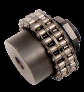
51 TORQUE LIMITERS WITH CHAIN COUPLING LCG 51 LC Torque limiter connected to the coaxial pinion hub through a double chain. Easy adjustment of desired torque through lock nut. The two friction elements dished clutch are burnished. TYPE PART max. N A B B C C E F G I L DIS. chain Z weight NUMBER torque springs max max mm ang. pitch teeth Kg LCG , , /8 X 7/ ,000 LCG , , /8 X 7/ ,005 LCG , , /2 X 5/ ,500 LCG , , /2 X 5/ ,550 LCG , , /8 X 3/8 21 4,300 LCG , , /8 X 3/8 21 4,300 I C F L G B A E TORQUE LIMITERS WITH CHAIN COUPLING LCG LCG , , /4 X 7/ ,000 LCG , , /4 X 7/ ,010 LCG , , /4 X 7/ ,000 LCG , , /4 X 7/ ,100 LCG , , X 17 mm 21 18,000 LCG , , X 17 mm 21 18,100 LCG , , X 17 mm 25 27,000 LCG , , X 17 mm 25 27, CAD drawings available on our site Quantity, availability and prices on B2B Chiaravalli

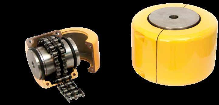
52 52 CHAIN COUPLING WITH KC COVER CHAIN COUPLING WITH KC COVER Suitable to connect two shafts in axis - With hardened sprockets - Provided with full cover, seals and O-ring for the protection from external contamination and also for an eventual lubrication of the coupling with grease. TYPE PART CHAIN PITCH A B C D E F G Min G Max Nm Weight NUMBER Kg. KC 3012 KC ,50 KC 4012 KC ,00 KC 4014 KC ,40 KC 4016 KC ,80 KC 5014 KC ,50 KC 5016 KC ,20 KC 5018 KC ,00 KC 6018 KC ,20 KC 6020 KC ,50 KC 6022 KC ,3 KC 8018 KC ,7 KC 8020 KC ,2 KC 8022 KC ,3 KC KC ,0 KC KC ,0 KC KC ,0 C A F G G E D B CAD drawings available on our site Quantity, availability and prices on B2B Chiaravalli


53 SPECIAL COMPONENTS MANUFACTURING We produce high precision Gears and Special Mechanical Components. A large and varied range of modern CNC machine tools assures large capacity production at high quality level. Chiaravalli Group SpA co-workers, highly skilful and motivated by a great spirit of belonging to the company, operate using the most modern CAE and CAD-CAM technologies. The production is certified and assured using three-dimensional high precision measuring machines. Chiaravalli Group SpA your technological partner for high quality production. 12
 integrates and completes our range of Mechanical Transmission products.")


54 WORM SCREW JACKS The new line of Worm Screw Jacks named CHT (Chiaravalli High Tech) integrates and completes our range of Mechanical Transmission products. This new line of products is manufactured using high quality materials, manufactured with absolute precision, making use of the modern machinery fleet of the companies belonging to Chiaravalli Group SpA. The basic elements that make up the final product Screw Jack are made in large series, rigorously checked and put in stock. Special virtual software developed by Chiaravalli Group SpA enables our customers to first view the various elements of the required screw jack and then, in the second phase, to order it with absolute precision and confidence. Chiaravalli Group SpA is engaged to ensure the delivery of this product in very short time, with quality and precision.
GIFLEX GE-T COUPLINGS with FLEXIBLE SPIDER
 GIFLEX GE-T S with FLEXIBLE SPIDER TORSIONAL FLEXIBLE S PRECISE EXECUTION HUB B HUB A INTRODUCTION Flexible torsion couplings, which are connecting devices between rotating shafts, are designed to ensure
GIFLEX GF COUPLINGS with POLYAMIDE SLEEVE
 GIFLEX GF S with POLYAMIDE SLEEVE DUAL CURVATURE FLEXIBLE TOOTHED S PRESENTATION The GIFLEX range of flexible toothed couplings are commercial couplings for general applications, which are however manufactured
FLEXIBLE COUPLINGS - RIGID COUPLINGS Up to Nm of torque and 205 mm bores
 Edition 10/2014 www.comintec.it FLEXIBLE COUPLINGS - RIGID COUPLINGS Up to 130.000 Nm of torque and 205 mm bores (BACKLASH FREE) Technology for Safety FLEXIBLE COUPLINGS - RIGID COUPLINGS (BACKLASH FREE):
BACKLASH FREE AND STANDARD JAW COUPLING
 BACKLASH FREE AND STANDARD JAW COUPLING Up to 9.600 Nm of torque and 130 mm bore GAS/SG e GAS 25 Technology for Safety GAS/SG-ST - backlash free jaw coupling «in steel»: introduction Made in steel fully
BACKLASH FREE AND STANDARD JAW COUPLING
 BACKLASH FREE AND STANDARD JAW COUPLING Up to 9.600 Nm of torque and 130 mm bore GAS/SG e GAS 25 Technology for Safety 10-2018 GAS/SG-ST - backlash free jaw coupling «in steel»: introduction Made in steel
Vibration damping precision couplings
 Vibration damping precision couplings In light of the advantages of elasticity, strength, resilience, and damping effects, elastomer materials are now being used in most areas of mechanical engineering.
Flexible Couplings N-BIPEX Series
 Flexible Couplings Series /2 Overview /2 Benefits /2 Application /3 Function /3 Design /4 Technical specifications /6 Type BWN /6 Selection and ordering data /7 Spare and wear parts /7 Selection and ordering
RIGIFLEX -N RADEX -N. Steel laminae coupling. Steel laminae coupling. You will find continuously updated data in our online catalogue at
 117 Table of contents 117 Coupling selection steel laminae coupling 119 Description of coupling 121 General information 122 Types and applications 123 Technical data 124 Standard types 126 Special types
FLEXIBLE COUPLINGS - RIGID COUPLINGS Up to Nm of torque and 205 mm bores
 Edition 10/2014 www.comintec.it FLEXIBLE COUPLINGS - RIGID COUPLINGS Up to 130.000 Nm of torque and 205 mm bores (BACKLASH FREE) Technology for Safety FLEXIBLE COUPLINGS - RIGID COUPLINGS (BACKLASH FREE):
Flexible couplings. Flexible Torsion shaft couplings... LB Coupling. BICO-TL Coupling...Technical data, Service faktor.
 Flexible couplings Flexible Torsion shaft couplings... LB Coupling...Technical data, Service faktor... Dimensions, Type of rubber BICO-TL Coupling...Technical data, Service faktor... Dimensions, Type of
Installation and Operating Instructions for ROBA -ES couplings Type 940. _. _ Sizes 14-48
 Table of contents: Please read and observe this Operating Instruction carefully. A possible malfunction or failure of the clutch and damage may be caused by not observing it. Page 1: - Table of contents
Flexible Couplings BIPEX Series
 Siemens AG 2011 Flexible Couplings BIPEX Series /2 Overview /2 Benefits /2 Application /3 Design /4 Technical data /5 Type BWN /5 Selection and ordering data /6 Type BWT /6 Selection and ordering data
Accessories smart additions for efficiency and intelligent performance
 smart additions for efficiency and intelligent performance Metal bellows couplings Perfectionists you can count on Metal bellows couplings are designed for the highest requirements in servo drive technology.
Jaw Couplings REK DCO
 elastic for dynamic applications with curved jaws Features Compensation of axial, radial and angular misalignments Adsorbs vibrations Progressive torsion spring properties due to primarily pressurised
Flexible Couplings BIPEX Series
 Siemens AG 2011 Flexible Couplings BIPEX Series /2 Overview /2 Benefits /2 Application /3 Design /4 Technical data /5 Type BWN /5 Selection and ordering data /6 Type BWT /6 Selection and ordering data
FLENDER Standard Couplings
 FLENDER Standard Couplings N-BIPEX FLENDER couplings Catalog MD 10.1 N Edition October 2016 Related catalogs ARPEX MD 10.2 High Performance Couplings Bucket Elevator Drives MD 20.2 E86060-K5710-A121-A1-7600
Safety Coupling Overview
 Safety Coupling Overview Safety couplings are used to minimize expensive damage when a collision occurs in a high performance servo drive system. When a collision occurs, the safety coupling will stop
CLAMPING ELEMENTS SELF-CENTRING RCK 15 TYPE SELF-CENTRING RCK 13 TYPE
 CLAMPING ELEMENTS The clamping system connects one or two component parts solidly to the drive shaft, which allow motion to be transmitted or to withstand an axial thrust. Friction connection enables gaps
Flexible Couplings BIPEX Series
 Siemens AG 2008 Flexible Couplings BIPEX Series /2 Overview /2 Benefits /2 Application /3 Design /4 Technical data /5 Type BWN /5 Selection and ordering data /6 Type BWT /6 Selection and ordering data
technology made in Italy
 technology made in Italy GB RD * * VS made in China Technology Made in Italy Since 1955 Varvel has been making speed reducers and variators for light industry applications. Reliable partner in power transmission
Roller chains TPM - QRC pag. 40 Roller chains RCX pag. 43 Conveyor chains CRT pag. 45 Chain guide rails in polyethylene pag. 48
 INDEX Sprockets - Platewheels pag. 2 Asa sprockets - platewheels pag. 20 Duplex platewheels for two simple chains pag. 26 Stainless steel sprockets - Aisi 304 L - Simplex sprockets hardened teeth pag.
COUPLINGS HRC FLEXIBLE COUPLINGS CHAIN SHAFT COUPLINGS SPLINE CLUTCHES TORQUE LIMITERS TORQUE LIMITER COUPLINGS
 COUPLINGS HRC FLEXIBLE COUPLINGS CHAIN SHAFT COUPLINGS SPLINE CLUTCHES TORQUE LIMITERS TORQUE LIMITER COUPLINGS FLEXIBLE COUPLINGS HRC TYPE Hercus HRC Couplings are designed for general-purpose applications
COUPLERS 5. Fax: +44 (0)
") COUPLERS Fax: +44 (0)1992 09890 3 COMPOSITE JAW COUPLERS (SERIES FS) L1 2.0 mm Max L2 2.0 mm Max L3 Bore B s 032-037 s 02-08 max features Low mass Freedom from corrosion Good damping properties Low cost
COUPLERS Fax: +44 (0)1992 09890 3 COMPOSITE JAW COUPLERS (SERIES FS) L1 2.0 mm Max L2 2.0 mm Max L3 Bore B s 032-037 s 02-08 max features Low mass Freedom from corrosion Good damping properties Low cost
Flexible pin & bush coupling
 Technical data KX-D Technical data Torque [Nm] NBR 80 Sh-A GJL Steel Dyn. torsion spring stiffness [Nm/rad] Max. speed Max. speed Rated Max. Vibratory [rpm] with Max. bore [mm] [rpm] with Max. bore [mm]
Inkoturn couplings. INKOMA - GROUP Couplings. Product description. Inkoturn couplings IKT. FRANCIS AND FRANCIS Ltd.
 Product description The INKOM Inkoturn coupling (IKT) is a flexible coupling with high torsional rigidity, which has been developed for applications requiring high speed and where shaft is present. INKOM
CHIARAVALLI Trasmissioni spa
 INDEX Sprockets - Platewheels pag. 2 Asa sprockets - platewheels pag. 20 Duplex platewheels for two simple chains pag. 26 Stainless steel sprockets - Aisi 304 L - Simplex sprockets hardened teeth pag.
Flexible Couplings RUPEX Series
 Flexible Couplings RUPEX Series /2 Overview /2 Benefits /2 Application /2 Design /4 Function /4 Technical data /6 Type RWN hub material grey cast iron /6 Selection and ordering data / Type RWS hub material
Jaw Couplings REK DQO
 Jaw s REK DQO elastic for dynamic applications with radially mountable elastomer cushions 40-1 Features s up to 169 000 Nm Compensation of axial, radial and angular misalignments Adsorbs vibrations Progressive
Coupling description. Disc pack with bolts
 Coupling description RADEX -N couplings are designed to transmit torque between drive and driven components via steel hubs and flexible metallic elements commonly known as discs. The combination of these
Types and operating description
 22 Flexible jaw and 24 -NORM Types and operating description ROTEX Flexible jaw and 73 74 75 76 78 79 REVOLEX Technical data Type KX-D, material cast Type KX-D, material steel Type KX-D with brake disk
Coupling Options for Every Application
 Coupling Options for Every Application Bellows Couplings High torsional rigidity, low inertia, zero backlash and misalignment compensation Can be used at temperatures up to 570 F without any limitations
Flexible Couplings N-EUPEX Series
 Flexible Couplings N-EUPEX Series /2 Overview /3 Benefits /3 Application /3 Function /4 Design / Technical data /10 Type A for easy elastomer flexible replacement /10 Selection and ordering data /11 Type
Highly Flexible Couplings ELPEX Series
 Siemens AG 2015 Highly Flexible Couplings ELPEX Series /2 Overview /2 Benefits /2 Application /2 Design /4 Configuration /5 Technical data /6 Types ENG/ENGS /6 Selection and ordering data /7 Types EFG/EFGS
Table of contents. Description of couplings 3. Coupling selection 4. Displacements 5. Selection of standard IEC motors 6
 Table of contents Description of couplings 3 Coupling selection 4 Displacements 5 Selection of standard IEC motors 6 Properties of standard spiders 7 Hub designs 8 Cylindrical bores and spline bores 9
Bevel gearboxes. Catalogue
 Bevel gearboxes Catalogue INDEX Bevel gearbox description... page 2 Manufacturing features... page 2 Materials and components... page 4 Bevel gearbox selection... page 5 Thermal power limit... page 7
ROTEX GS Backlash-free jaw couplings
 ROTEX GS Technical description ROTEX GS is a three-part, axial plug-in coupling backlash-free under prestress. It is convincing even with critical applications by its backlash-free power transmission,
TOOLFLEX RADEX -NC. Backlash-free shaft couplings: backlash-free flexible shaft couplings. backlash-free torsionally stiff bellow-type couplings
 Backlash-free shaft couplings: ROTEX GS backlash-free flexible shaft couplings TOOLFLEX backlash-free torsionally stiff bellow-type couplings RADEX -NC backlash-free torsionally stiff servo lamina coupling
For advanced drive technology. Backlash-free shaft couplings: TOOLFLEX. Backlash-free shaft couplings ROTEX GS TOOLFLEX. Metal bellow-type couplings
 Backlash-free shaft couplings: ROTEX GS Backlash-free shaft couplings ROTEX GS TOOLFLEX TOOLFLEX Metal bellow-type couplings 9 Backlash-free shaft coupling Technical description ROTEX GS is a 3-part, axial
Types and operating description
 22 Flexible jaw and pin & bush couplings 24 69 70 71 72 Selection of standard IEC motors Type PKZ, two-part and PKD, three-part Type PKA, drop-out center design coupling Displacements / elastomer sets
Eflex and Powerpin Flexible Couplings
 Eflex and Powerpin Flexible s Accepts parallel, angular and axial misalignment Torsionally flexible Simple assembly Wide range of standard designs No lubrication 80 or 90 shore hardness close fitting elements
TORSIONALLY RIGID COUPLING
 TORSIONALLY RIGID COUPLING Up to 130.000 Nm of torque and 205 mm bore GTR 7 Technology for Safety GTR - torsionally rigid coupling: introduction Made in steel fully turned with standard treatment of phosphating.
Highly Flexible Couplings ELPEX-S Series
 Highly Flexible Couplings ELPEX-S Series /2 Overview /2 Benefits /2 Application /2 Design /4 Function /4 Configuration /6 Technical data /9 Type E /9 Selection and ordering data /10 Type ESD /10 Selection
DRIVE-TECHNOLOGY INKOMA - GROUP. Inkoturn couplings
 INKOM-GROUPINKOM - DRIVE-TECHNOLOGY GROUP Inkoturn couplings INKOM-GROUP Headoffice Sitz der INKOM Maschinenbau GmbH Neue Reihe 44 D - 3862 Schandelah - Germany phone: +49/(0)5306-922-0 fax: +49/(0)5306-922-50
Curved Jaw. In This Section: CJ Series GS Series. CJ-1
 In This Section: Series GS Series www.lovejoy-inc.com 49-1 Curved Jaw Safety Warning When using Lovejoy products, you must follow these instructions and take the following precautions. Failure to do so
Backlash-free safety couplings. Backlash-free safety couplings. Product information. Optimal safety has a name: Guaranteed by two systems:
 ;;Engaged ;;Engaged Backlash-free safety couplings Product information Optimal safety has a name: Backlash-free safety couplings Guaranteed by two systems: ;;;; Locking Locking element - cylinder roller
KTR Torque Limiters Overload Protection Systems
 KT Torque Limiters Overload Protection Systems UFLEX - Friction Disk - Zero Backlash Ball Detent KT SI - Ball/oller Bearing Style KT SI Compact - Zero Backlash Ball Detent Catalog Contents (Metric) Page
GEAR-COUPLINGS. Series LX GLX S-NX
 GEAR-COUPLINGS Series LX GLX S-NX CONTENTS Application 3 Quality and production 3 Design and characteristics 3 selection 4-5 Key connections 6 Shrink-fit connections 7 Standard design with one-piece housing
Flexible Couplings N-EUPEX Series
 Flexible Couplings N-EUPEX eries /2 Overview /3 Benefits /3 Application /3 Function /4 Design / Technical data /10 Type A for easy elastomer flexible replacement /10 election and ordering data /11 Type
Flexible Couplings N-EUPEX Series
 Flexible Couplings N-EUPEX Series /2 Overview /3 Benefits /3 Application /3 Function /4 Design / Technical data /10 Type A for easy elastomer flexible replacement /10 Selection and ordering data /11 Type
BEVEL GEARS. STANDARD EXECUTION page 5 SPECIALE CH EXECUTION GLEASON SYSTEM 9 DIN 3971 EXECUTION 19 SPIRALS 25 SPECIAL PRODUCTIONS ON REQUEST 27
 BEVEL GERS STNDRD EXECUTION page 5 SPECILE CH EXECUTION GLESON SYSTEM 9 DIN 3971 EXECUTION 19 SPIRLS 25 SPECIL PRODUCTIONS ON REQUEST 27 6 BEVEL GERS BEVEL GERS BEVEL GER WITH STRIGHT TEETH SPECIL CH EXECUTION
(d) Bore Size Check from Dimensions table (page 112) that chosen flanges can accommodate required bores.
 Bore Size Check from Dimensions table (page 112) that chosen flanges can accommodate required bores.") Fenaflex Couplings The Fenaflex coupling is a highly flexible, torsionally elastic coupling offering versatility to designers and engineers with a choice of flange combinations to suit most applications.
Fenaflex Couplings The Fenaflex coupling is a highly flexible, torsionally elastic coupling offering versatility to designers and engineers with a choice of flange combinations to suit most applications.
Standard with cone bushing. Backlash-free Safety Clutch
 EAS -Compact ratchetting clutch/synchronous clutch The Backlash-free Safety Clutch for Standard with cone bushing Packaging Machinery Machine Tools Paper Machinery Indexing Drives Servo Motors EAS -NC
Operating / Assembly Instructions Type A and CS Coupling
 Page: 1 of 14 Subject Index 1. Technical Data 2. Hints 2.1. General Hints 2.2. Warning and Safety Hints. 2.3. General Hints to Danger. 2.4. Proper use. 3. Storage. 4. Assembly. 4.1. Coupling components.
Shaft Couplings Flange-Couplings Rigid Shaft Couplings Flexible Couplings
 Shaft Couplings Flange-Couplings Rigid Shaft Couplings Flexible Couplings 44 Edition 2013/2014 RINGSPANN Registered Trademark of RINGSPANN GmbH, Bad Homburg 2 Table of Contents Flange-Couplings Page Flange-Couplings
Rodless cylinders. Series General. Construction characteristics. Technical characteristics. Use and maintenance
 Series 1600 Rodless cylinders General The purpose of producing a rodless cylinder is to provide a space saving option over conventional cylinders. On a traditional rod type cylinder, the total space occupied
Huco Dynatork Flexible Couplings
 Huco Dynatork Flexible Couplings Flexible Couplings The Company & Its Products Huco products are manufactured in Hertford, England, in a modern plant equipped with all necessary design, development, toolroom
BoWex FLE-PA DBGM BoWex-ELASTIC DBP
 BoWex FLE-PA DBGM BoWex-ELASTIC DBP Flange coupling for I. C.-engines BoWex BoWex-FLE-PA BoWex ELASTIC BoWex FLE-PA couplings are torsionally rigid curved-tooth flange couplings, made from a combination
Description Symbol Definition or explanation Rated torque T KN Torque that can continuously be transmitted over the entire permissible speed range
 Coupling selection Normally the is selected according to the nominal torque ( ) shown in the list of technical data, like all other coupling systems. In all cases the torque ( ) must exceed the maximum
Highly Flexible Couplings ELPEX-B Series
 Siemens AG 2015 Highly Flexible Couplings ELPEX-B Series /2 Overview /2 Benefits /2 Application /2 Design / Technical data /5 Type EBWN /5 Selection and ordering data /6 Type EBWT /6 Selection and ordering
PRECISION BELLOWS COUPLINGS
 PRECISION BELLOWS COUPLINGS Bellows couplings are used where precise rotation, high speeds, and dynamic motion must be transmitted. They exhibit zero backlash and a high level of torsional stiffness, offering
Highly Flexible Couplings ELPEX-B Series
 Siemens AG 200 Highly Flexible Couplings ELPEX-B Series /2 Overview /2 Benefits /2 Application /2 Design / Technical data /5 Type EBWN /5 Selection and ordering data /6 Type EBWT /6 Selection and ordering
BoWex FLE-PA. BoWex FLE-PAC. KTR-N Sheet: Edition: EN 1 of BoWex FLE-PA / FLE-PAC Operating/Assembly instructions
 1 of 17 is a torsionally rigid flange coupling. It is able to compensate for shaft misalignment, for example caused by manufacturing inaccuracies, thermal expansion, etc. BoWex FLE-PA BoWex FLE-PAC Drawn:
BoWex Curved-tooth gear coupling, shaft coupling. BoWex-ELASTIC High flexible flange coupling. MONOLASTIC Single-part, flexible flange coupling
 Curved-tooth gear coupling, shaft coupling Torsionally rigid flange coupling U.S. Patent 5,586,938 High flexible flange coupling Single-part, flexible flange coupling EP 0853203 U.S. Patent 6,117,017 Pump
Installation and Operational Instructions for ROBA -D Couplings Type 91_. _
 Please read the Installation and Operational Instructions carefully and follow them accordingly! Ignoring these Instructions may lead to malfunctions or to coupling failure, resulting in damage to other
Selection Tool. on the Internet at in the section MÄDLER -Tools. Other sizes and designs on request. Connecting Shafts Page 766
 Couplings Overview Friction Clutches Friction Clutches Type B Axial Arrangement Friction Clutches Type C Transversal Flexibility Sliding Hubs with Torsionally-Flexible Coupling Multi-Disk Friction Clutches
LIGHTWEIGHT AND COMPACT. SERIES SL Nm. single-position multi-position. THE ultimate COUPLING from Nm
 LIGHTWEIGHT AND COMPACT L SAFETY COUPLINGS TOQLIGHT SEIES SL 5 700 Nm THE ultimate COUPLING from 5 700 Nm SEIES SL DESIGN / FEATUES Extremely lightweight construction Up to 60 % weight reduction in comparison
BALL AND ROLLER TORQUE LIMITERS DSS or DSR : introduction
 BALL AND ROLLER TORQUE LIMITERS or : introduction Precise torque setting by adjusting the radially balanced locking nut. The innovative regulation of the nominal torque by measuring the H dimension allows
PK couplings. Product description. PK couplings
 Product description The INKOMA-PK coupling is machine component designed to transmit torque between axially parallel, radially offset shafts. The coupling permits both static and dynamic stepless adjustment
Product description. PK couplings
 Product description The INKOMA-PK coupling is machine component designed to transmit torque between axially parallel, radially offset shafts. The coupling permits both static and dynamic stepless adjustment
RADEX -NC Servo lamina couplings
 RADEX -NC Servo lamina couplings Technical description RADEX -NC is a line specifically developed for servo technology. In this coupling a set of torsionally rigid steel laminas that are soft in bending
METALDRIVE Disc couplings
 ETADRIVE Disc couplings ETADRIVE couplings are fully made of steel and are used in all applications where high reliability, precision and no maintenance are required. Features All steel made Superior disc
Flexible Couplings and Hub-shaft Connections COUPLINGS
 Flexible Couplings and Hub-shaft Connections COUPLINGS High-reliability Metal Plate Spring Format Realizing Its Best Shape Through Finite Element Analysis is an ultrahigh-rigidity flexible coupling derived
Pin-guided clutch with three flyweights
 S-Type Pin-guided clutch with three flyweights Construction and mode of operation 2 5 4 3 3 1 1 5 2 6 4 = Hub = Flyweights = Cylindrical pin = Tension spring = Lining = Clutch drum / Cover disc Low noise
Shaft Design. Dr. Mostafa Rostom A. Atia Associate Prof.
 Shaft Design Dr. Mostafa Rostom A. Atia Associate Prof. 1 Loading modes A shaft is a rotating member, usually of circular cross section, used to transmit power or motion. It provides the axis of rotation,
PROPULSION EQUIPMENT DOCUMENTATION SHEET. Propulsion Equipment
 PROPULSION EQUIPMENT General Vessels like rescue boats, patrol boats and anchor handling boats have to show 100 percent performance, even in the most extreme conditions. These so called s pecial seagoing
RACK JACK. Synchronous Lifting Systems
 RACK JACK Synchronous Lifting Systems RACK JACK (ROUND RACK TYPE) Operation The Rack Jack from WMH Herion provides simple synchronous lifting motion. The system of rack and pinion transforms linear motion
Semiflex Standard Symbiosis of performance and compact design. Semiflex. The Semiflex series
 SE_S_1/06 compact design The Semiflex series Standard F series Bore diameter up to 120 mm Torque ( ) 44 Nm to 7.040 Nm Semiflex Semiflex is a high-precision coupling in a compact design and with no restoring
Bearing retention and clearances
 Bearing retention and clearances Bearing retention 9 Radial retention 9 Axial retention 91 Positioning of single bearing assemblies 91 Positioning of two bearing assemblies 92 Axial retention processes
SCHMIDT-KUPPLUNG GmbH
 Schmidt-Kupplung SCHMIDT-KUPPLUNG GmbH Schmidt-Kupplung About us About us In the early 1960s Richard Schmidt developed of propulsion systems for rockets in a zero-gravity environment. Among the possible
STRAIGHT SPUR GEARS and RACKS
 STRAIGHT SPUR GEARS and RACKS SPUR GEARS WITH LATERAL HUB page 4 SPUR GEARS WITHOUT HUB 7 RACKS 9 SPUR GEARS AND RACKS SPUR GEARS AND RACKS SPUR GEARS WITHOUT HUB SPUR GEARS WITH LATERAL HUB RACKS STRAIGHT
Group 078
 1-078-080111 Group 078 EUROTEC TIRE COUPLINGS American Metric s eurotec tire couplings provide all the desirable features of an ideal flexible coupling, including Taper Lock installation. The eurotec tire
Bell-house Mounted Arrangement. Highly Flexible K Coupling
 Bell-house Mounted Arrangement. Highly Flexible K Coupling K Couplings for bell-house mounted arrangements are the only coupling type providing a blind assembly connection. They are specially designed
POWER TRANSMISSION RIGID COUPLINGS MINI MINI
 POWER TRANSMISSION RIGID COUPLINGS 2 RIGID COUPLINGS FEATURES The Mini coupling is a backlash-free, torsion proof, bending elastic and, above all, maintenance-free steel coupling made in one piece. It
Semiflex Compact Plus For extremely axially limited space. Semiflex. The Semiflex series
 SE_CP_1/06 The Semiflex series Standard F series Symbiosis of performance and compact design Bore diameter up to 120 mm Torque ( ) 44 Nm to 7.040 Nm Semiflex Semiflex is a high-precision coupling in a
SITEX ST Couplings SITEX ST
 STX ST Couplings STX ST STX ST couplings Description STX ST couplings are fully manufactured in high quality steel. They are made of 1 or 2 geared hubs which are coupled with one sleeve through which the
METALDRIVE Disc Couplings
 ETADRIVE Disc Couplings ETADRIVE ETADRIVE disc couplings ETADRIVE couplings are fully made of steel and are used in all applications where high reliability, precision, and no maintenance are required.
Profi le rail guides LLR
 Profi le rail guides LLR Content The SKF brand now stands for more than ever before, and means more to you as a valued customer. While SKF maintains its leadership as the hallmark of quality bearings throughout
TORQLIGHT SAFETY COUPLINGS
 LIGHTWEIGHT AND COMPACT single-position TOQLIGHT SAFETY COUPLINGS SEIES SL 10 700 Nm THE ULTIMATE COUPLING FOM 10 700 Nm SEIES SL DESIGN / FEATUES Extremely lightweight construction Up to 60 % weight reduction
For advanced drive technology CLAMPEX. Shaft-Hub-Connection. KTR Precision Joints CLAMPEX
 technology CLAMPEX Shaft-Hub-Connection CLAMPEX KTR Precision Joints 07 technology Table of contents Page Brief information 09 Selection and calculation -5 CLAMPEX -Selection Shaft diameter = d 0 10 0
High Pressure Gear Pumps KP 5
 High Pressure Gear Pumps KP 5 Construction 1 6 2 9 8 4 5 7 3 1 Housing 2 Gearing 3 Drive shaft end 4 Flange cover 5 Roller bearing 6 Sliding plates 7 Lip-type shaft seal 8 Plain bearing 9 Housing gasket
10 Thrust ball bearings
 10 Thrust ball bearings Designs and variants.............. 1010 Single direction thrust ball bearings... 1010 Double direction thrust ball bearings.. 1010 Cages............................ 1010 Bearings
Series J Shaft Mounted Gearbox
 Series J Shaft Mounted Gearbox Technical Up to - 600kW / 57,000 Nm Industrial Gearbox CJ-2.00GBA1211 PRODUCTS IN THE RANGE Serving an entire spectrum of mechanical drive applications from food, energy,
Locking Assemblies & Locking Elements
 US 01 2016 Locking Assemblies & Locking Elements Partner for Performance www.ringfeder.com Welcome to your system supplier for every aspect of power transmission Today s RINGFEDER POWER TRANSMISSION GMBH
Sheet 1 Variable loading
 Sheet 1 Variable loading 1. Estimate S e for the following materials: a. AISI 1020 CD steel. b. AISI 1080 HR steel. c. 2024 T3 aluminum. d. AISI 4340 steel heat-treated to a tensile strength of 1700 MPa.
PNCE ELECTRIC CYLINDER
 ELECTRIC CYLINDER INDEX Characteristics 1 Structural design 2 How to order 3 Technical data 4 Dimensions 11 Accessories 12 Lubrication position 2 Motor adapter with coupling 2 Motor side drive with timing
High performance metal disk coupling SERVOFLEX SFF (N)
") High performance metal disk coupling SERVOFLEX SFF (N) Best design for the latest servo motor SERVOFLEX for feed shaft which introduce the high precision clamp method Coupling outer diameter, lineup for
High performance metal disk coupling SERVOFLEX SFF (N) Best design for the latest servo motor SERVOFLEX for feed shaft which introduce the high precision clamp method Coupling outer diameter, lineup for
Size 00 Size 0-5 Size 6-8. Technical Data. Setscrew 1TF 2TF 3TF 3) 2) R Pilot bore max.
 2) R Pilot bore max.") Standard for a torque range up to 6800 Nm Standard zinc-coated and yellow passivated ting possible while in place Asbestos-free and rust-resistant friction linings Securing of the setting nut by locking
Standard for a torque range up to 6800 Nm Standard zinc-coated and yellow passivated ting possible while in place Asbestos-free and rust-resistant friction linings Securing of the setting nut by locking
SITEX ST Couplings SITEX ST
 STX ST Couplings STX ST Contents STX ST Couplings Page Description 97 Features 97 STX ST executions 98 ST type C 99 ST type CV 100 ST type CF A-B-C (AMA) 101 ST type CF D--F 102 Coupling selection 103
Flexible Couplings 44
 Flexible Couplings 44 RINGSPANN Registered Trademark of RINGSPANN GmbH, Bad Homburg MTY (81) 83 54 10 18 Why RINGSPANN Flexible Couplings? No connection of shafts without clutches It is a well-known fact
Highly Flexible Couplings ELPEX-B Series
 Highly Flexible Couplings ELPEX-B Series /2 Overview /2 Benefits /2 Application /2 Design /4 Technical data /5 Type EBWN /5 Selection and ordering data /6 Type EBWT /6 Selection and ordering data / Type