R-134a. APCY Series Screw Chillers. SKM Compact Screw Chillers APCY Series - R-134a. Range 50 TR to 455 TR (176 kw to 1600 kw)
|
|
|
- Brandon Hutchinson
- 6 years ago
- Views:
Transcription


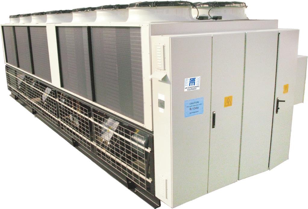


1 SKM Compact Screw Chillers APCY Series - R-34a R-34a APCY Series Screw Chillers Range 50 TR to 455 TR (76 kw to 600 kw) facebook.com/skmaircon Sharjah Economic Excellence Award winner
2 APCY Series - R-34a Contents Introduction...2 Legend... 2 Nomenclature...2 General Features...3 Main Component Features...3 Microprocessor Control...4 Optional Features...6 Engineering Specifications...8 Capacity Ratings...4 Capacity Correction &Limits...26 Water Pressure Drop...27 Selection Procedure...29 Electrical Data...30 Typical Wiring Diagram...39 Power Entry Connection...39 Dimensional Data... Loading points...52 Location And Space Requirements...55 Water Piping Practices...56 Guide Specifications...60 Introduction SKM APCY Series environment friendly (R-34a) Air Cooled Screw Chillers are designed and manufactured to provide utmost performance, efficiency, reliability, to meet the requirements and long life from Gulf s severe climatic condition. Legend The following legends are used throughout this manual: APCY Series Chillers have low noise and minimum vibration ideal for vast range of applications including hotels, high-rise buildings, stores, hospitals, and modern cooling applications of modern manufacturing industries. cfm... Cubic feet per minute EER... Energy Efficiency Ratio Hz... Hertz kw... Kilowatts kg... Kilogram lbs... Pounds l/s... Liters per second MBH... Btu/hr x 000 Ph... Phase PI... Power Input of Compressor TR... Tons of Refrigeration V... Volts APCY units are factory assembled, leak tested, evacuated, internally wired and fully charged with refrigerant R-34a. Every unit is fully tested before delivery and is ready for installation. Nomenclature Air Cooled Packaged Chillers Y-version Screw Compressor, R-34a Power Supply Frequency Size S-Standard Efficiency H-High Efficiency 5 : 50 Hz 6 : 60 Hz A P C Y S Y Power Supply Code Y : 380V/3Ph/50Hz Y: 45V/3Ph/50Hz P : 4V/3Ph/50Hz R : 380V/3Ph/60Hz E : 460V/3Ph/60Hz T : 2V/3Ph/60Hz (Consult SKM) APCY Chillers are rated on accordance with AHRI 550/590. APCY Chillers are designed and manufactured as per SKM Quality, Environment, Occupational, Health and Safety Management Systems that confirms with ISO 900:08, ISO 00:04 and OHSAS 800:07. SKM provides qualified service and stock of replacement parts in all major cities of the G.C.C. countries, Egypt, Jordan, and Pakistan. See back cover for details or call SKM. SKM Airconditioning LLC SKM reserves the right to change, in part or in whole the specifications of its Air Conditioning Equipment at any time in order to add the latest technology. Therefore, the enclosed information may change without any prior notice. You name it...we cool it. 2
3 APCY Series - R-34a General Features High COP APCY Series chillers provide tremendous savings in operating costs by using high efficiency, semi hermetic screw compressor. High COP is made possible due to perfect screw profile and precise machining. The stepless capacity control provides precise capacity as required by the system load, and thus giving higher part load efficiencies. The compressor can be loaded from 25 or 35 to 00% of capacity depending upon the requirement through state of the art microprocessor control which precisely monitors the water temperature and accurately modulates the compressor accordingly. Maintenance Free Operation APCY Series chillers have compact design and are supplied as a complete package, ready to be wired and piped for operation. Screw compressors in SKM APCY Series provide virtually maintenance free operation as there are fewer moving parts. Special bearings facilitate longer run periods of compressor without any need for maintenance. Wide Operating Range Condensers Condenser coils are manufactured from seamless Hi-x copper tubes mechanically bonded to aluminium fins to ensure optimum heat transfer. All coils are tested against leakage by air pressure of 450 psig (302 kpa) under water. All standard coils are 3 rows,6 FPI (.59 mm fin spacing),3/8 (9.5mm) O.D. tubes. Condenser fin materials should be matched with site conditions to inhibit coil corrosion and ensure extended equipment life. For different application requirements, other optional condenser fin materials are available: Copper fins Copper fins electro-tinned after manufacturing Precoated Aluminum fins The pre-coated is hydrophobic polyurethane resin. This option provides substantial corrosion protection beyond standard coil construction. Aeris Guard Coil Coating. The Aeris Guard Coil is a self etching high performance modified epoxy finish that is specifically designed to coat and protect Aluminum and Copper surfaces. In addition, the coating is ideal for the protection of ferrous and non ferrous materials. APCY chillers are designed, as standard, to operate at a wide range of ambient temperatures from 25oF (-4 o C) to 27.4oF (53 o C). Some models can operate up to 3oF (55 o C). Consult SKM. Main Component Features Condenser Fans The condenser fans are propeller type, aluminium alloy blades, directly driven by electric motors. Motors are Totally Enclosed Air Over (TEAO) six pole with class F insulation and IP55 protection. The TEAO and class F insulation features ensure long life and are unique to SKM. Compressors APCY Series Chillers use high performance and high efficiency screw compressors which are with 5:6 ratio screw rotor profile designed specifically for modern refrigerant characteristics, double-walled rotor housing, robust in construction and have a very few moving parts to minimize noise and ensure rigidity. Screw Compressors are directly flanged on a three stage oil separator with low oil carry over and pressure drop demister to ensure minimal refrigerant dilution in the oil and maintain high oil viscosity. Oil sight glass, oil drain valve, oil heater, discharge check valve, discharge stop valve are available as standard. APCY screw compressors have excellent bearing life and superior compressor reliability. Screw compressors utilize the combination of axial and radial bearings and α axial balance piston design. Continuous (Stepless) capacity control system and automatic start unloading are provided as standard. All compressors are provided with motor winding temperature protection, discharge temperature protection, phase reversal protection, phase failure protection and oil level protection. The motors are factory wired to chiller unit control panel where the motor starters are located to control the operation of these motors. The fans are individually statically and dynamically balanced at the factory. Complete fan assembly is provided with suitable acrylic coated fan guard. Evaporator APCY evaporators are direct expansion, shell and tube, with removable head, and having, 2,3 or 4 refrigerant circuits. Evaporator shell is made of steel. Tubes of copper fixed to steel end plates. Baffles are provided in the water flow to increase heat transfer efficiency. Evaporators are provided with drain and vent plugs. Cooler shell is insulated with.0 (25mm) thick flexible closed cell insulation, K factor 0.28 Btu. in/ft².h.of (0.04W/m.oK). Maximum working pressure of waterside is 45 psig ( 000 kpa) and refrigerant side is psig (650 kpa). Electronic Expansion Valve APCY series chillers use electronic expansion valve for precise control refrigerant mass flow. Our electronic expansion valve improves EER (Energy Efficiency Ratio) at full & part-load conditions. Also it improves temperature control & increases the range of operating conditions. 3
 and 95% RH as per ASTM B7.")
4 APCY Series - R-34a Casing/Structure Frame The unit casing in APCY series chillers is made of zinc coated galvanized steel sheets conforming to JIS-G 3302 and ASTM A 653 which is phosphatized and baked after an electrostatic powder coat of approximately 60 microns. This finish and coating can pass a 000 hour in 5% salt spray testing at 95 F (35 C) and 95% RH as per ASTM B7. APCY chillers are assembled on rigid structural steel skid channels painted with one coat galvanized primer and one coat black enamel. The package is assembled for easy handling during transportation and robust support during installation and operation. Refrigerant Piping The refrigeration circuit piping is fabricated from ACR grade copper piping. Each refrigeration circuit includes filter drier, electronic expansion valve, and shut off valve. The refrigeration circuit suction line is insulated with ½ (3mm) wall thickness closed cell pipe insulation. Circuit breaker for control circuit. Remote/Off/Local selector switch. Microprocessor master board with graphical display. Microprocessor expansion boards as required. Electronic expansion valve control boards. Control Relays. Control circuit on/off switch and pump down switches. Volt free contacts for run, common fault and auto mode indications. Provision for accepting volt free contact for remote start/ stop. Control terminal blocks and power terminal blocks/bus bars. Microprocessor Controller Economizer All units are equipped with economiser circuit. Economiser operation improves both cooling capacity and efficiency by increasing sub cooling where part of the liquid refrigerant is flashed to an intermediate pressure which is used to cool the remaining liquid refrigerant. This flash refrigerant is then fed into a compressor where it helps to cool the vapour from the main circuit. The economiser channel is integrated into the control slide to enable sub cooling circuit to operate regardless of the compressor load condition. The components of an economiser cycle include thermostatic expansion valve, plate type heat exchanger, solenoid valve & ECO muffler kit. Control Panel The unit mounted chiller control panel enclosure is fabricated out of heavy gauge sheet steel in phosphatized powder coated baked finish. The enclosure conforms to IP54 as per guidelines in IEC 529. A hinged access door and key-fastener is provided for easy access and security. The panel is factory wired in accordance with NEC 430 & 4, labeled, tagged and features 2V / 2V controls. All compressors are with part winding start as standard. Individual compressor and condenser fan motor contactors. Thermal magnetic circuit breakers for compressors and condenser fan motors. Microprocessor control system is available for APCY series chiller as a standard feature. Our high energy efficient chiller has a full function microprocessor control unit designed to keep the chiller running at its most energy efficient level. It is a rugged microprocessor based controller that is designed for the hostile environment of HVAC industry. It provides flexibility with set points and control options that can be selected prior to commissioning a system or when the unit is live and functioning. Displays, alarms and other interfaces are accomplished in a clear and simple language that informs the user as to the status of the system. It is designed to safeguard the system that is being controlled, eliminate the need for manual intervention and to provide a simple but meaningful man-machine-interface. This controller provides complete operational control for the chiller and has built-in auto diagnostic capability that can signal normal operation or alarm conditions as well as shutting down the chiller or system, if necessary. Voltage monitoring module for protection against under voltage, over voltage, phase loss, phase reversal and phase unbalance of the incoming voltage. 4
5 APCY Series - R-34a The Main Features of the controller are as follows: System Control Philosophy A large graphical LCD Display (2.8 diagonal) with back-lit that can be seen in bright or dim lighting. A nine button generic keypad that is so user friendly, it rarely requires a reference manual. Battery backed up built in real time clock to program the chiller for 2 starts and 2 stops daily to provide the information about the running hours of the compressors. Multiple authorization levels to provide tight security of the control system. Two operating schedules per each day of the week and 8 holidays. The system provides last time enabled & disabled, number of cycles, and total run hours. Automatic Lead/Lag changeover of the compressors. Pump-down at the beginning and end of every circuit cycle. Capacity control based on leaving chilled water temperature. A special control zone based on leaving water temperature that reduces compressor cycling, and improved unit part load efficiency. Start/stop facility from remote through Volt Free Contact (VFC). Common Run, Fault and remote mode operation status volt free contacts provided for remote signaling. Display Information SKM APCY-S chillers offer a graphics LCD display which allows the operator to access different parameters of the chiller. Operator can view and change the set point of chiller parameters. The graphical display has lot of features, trending is one of the key features of graphical display, which shows last 25 samples with an appropriate scale to allow it to fit on the display. The well designed keypad with three function keys, four direction keys and two selection keys allows the operator to navigate through different Menu, such as: Status. Outputs. Inputs. Alarms. Graphs. Setpoint. Service tools. Lockout Reset. Lockout Alarm. Password. The unit may be enabled or disabled manually or through the use of an external signal from a building automation system. Control is based upon leaving chilled water temperature. How fast the temperature changes is calculated and capacity decisions are based upon the rate, the current temperature, and the control temperature zone. Capacity is never added if the system is moving toward the temperature target at an acceptable rate. The unit will monitor all control functions and stage the compressor to maintain the required operating capacity. Easy Accessible Measurements Include: Status of the chiller. Status of each circuit/compressor. Status of condenser fans. Leaving and Entering chilled water temperature. Suction pressure and temperature for each refrigerant circuit. Discharge pressure and temperature for each refrigerant circuit. Suction and discharge superheat for each refrigerant circuit. Oil pressure for each compressor. Winding temperature for each compressor. Ampere draw for each compressor. Expansion valve opening percentage. Ambient temperature. All active set points. Run time for each compressor. Number of compressor starts. Lockout and alarm status. Status of water flow switch, voltage monitor, compressor internal motor protector, oil level switch, run/stop input and pump down switches. Log of last 00 alarms. Lead compressor identification. Date and time. Graphs of all inputs and outputs. 5
6 APCY Series - R-34a System Protection The following system protection controls will automatically act to insure system reliability and protection of the unit. Low suction pressure protection. High discharge pressure protection. High discharge temperature protection. Low discharge pressure protection. Low oil pressure protection. Low oil level protection. High compressor motor winding temperature protection. Low superheat protection. High compressor ampere protection. Compressor internal thermal protection. Freeze protection. Under voltage, over voltage, phase loss, phase reversal and phase unbalance protection. Chilled water flow loss protection. Sensor error protection. Pump down. Anti-recycle. Time delay between stages. 4-Levels of passwords to restrict the intentional mishandling. Optional Features available for the Micro Controller BMS Communication BMS communication with the chiller microprocessor is possible through hardwired signals or major BMS protocols. Hard wired signals Volt free contacts for Run, Common fault and Auto mode indications and provision for remote start/stop are provided as standard feature. In addition to these, below options can be provided if specified. Emergency Stop A volt free contact from BMS to chiller, which is normally closed and opens on an emergency shut down condition. It will make the chiller to shut down immed -iately bypassing normal shut down procedure. Chilled water reset A 0-5VDC signal from BMS to chiller, which allows resetting chilled water set point around an acceptable range. BMS protocols The chiller controller is capable to interface with four major building management systems, which are BACnet, Modbus, Lonworks and Johnson N2, by adding optional hardware. This interface allows to monitor the status of chiller and individual circuits, all inputs and outputs, chilled water set point etc. The required BMS protocol and number of chillers needs to be specified during the time of order as costing of the BMS interface involves these parameters. PC Support Software PC software to communicate with APCY microprocessor is available as an optional feature. Software is named MCS-Connect and it can provide both local and remote communications to the chiller microprocessor. This program allows viewing the entire status of chiller, inputs, outputs, set points, alarms, graphs etc. Through proper authorization, changes can be made to the system. Configuration files can be transmitted to or received from the unit. Communication between PC and chiller microprocessor can be made through RS-232 serial port or Ethernet port. If there is more than one chiller, these chillers can be connected together via Rs-485 network which can support up to chillers. Access to this network can be local, via RS 232 or Ethernet connection, or remote via 4.4K Baud modem. Each chiller in the network must be assigned to a unique address. This address can be changed from the LCD/keypad of the unit or through MCS- Connect software. RS 232 transmission should not exceed 50 feet in length and RS 485 transmission should not exceed mile without repeater. For Ethernet communication, it is necessary to use a crossover cable when connected directly to a PC. This software can run with Windows 00 or newer version. Factory Installed Options Alternative Condenser Material Made of copper tubes and alternative fin material and/or protective coats. Condenser coil with Pre Coated Aluminum fins, specify (FAP). Condenser coil with A eris Coated Aluminum fins,specify (FAA). Condenser coil with Copper fins, specify (FC). Condenser coil with Aeris Coated copper fins, specify (FCA). Electrotinned copper fins for Condenser coil, specify (CFT) (consult SKM). Galvanized Frame (GFB) Hot dip galvanized after manufacture, steel frame and base. Evaporator Casing (ECA/ECG/ECS) Evaporator enclosed in a casing of Aluminium /Galvanized Steel / Stainless Steel, and injected with polyurethane foam..5 (38mm) insulation thickness. 6
7 APCY Series - R-34a Condenser Coil Guard (CGP) Galvanized wire mesh guard with painted finish for condenser coils. Recommended on ground level installations where coil needs to be protected against vandalism. Low Noise Fan & Motor (LNF) Low noise Fan & Motor assembly can be provided for applications where minimal unit sound is required. (consult SKM) Voltage Monitoring Module as per DEWA (DVM) Under voltage relay as per DEWA specification.this option is available for Dubai,UAE only. Evaporator Freeze Up Protection (EFP) Heating cable with thermostat to prevent evaporator freeze-up where low ambient temperatures below 32 o F (0 o C) are anticipated with/out chiller operation. Pressure Relief Valve (PRV) IP55 Control Panel Enclosure (ICP) To protect the chiller unit from being over-pressurized. Control Panel for special applications to meet IP55 requirements. Marine Paint (MP) Marine Painting on casing and steel structure, to improve corrosion resistance in coastal environments and off-shore locations. Compressor Sound Enclosure (CSE) compressor sound enclosure with insulated panels is mounted around the compressor, to reduce sound. ASME Stamped Evaporator Shell and Tube evaporator with ASME stamp. Pressure Guages(Suction/Discharge) (STE) (SDG) Suction & discharge pressure indication of each refrigerant circuit. Gauges are mounted outside the Control Panel. Extra Shut Off Valve (XFV) Extra Shut off valve in liquid line to fully isolate the filter drier. Suction Shut off Valve (SSOV) Screw compressors are with suction shut off valves to isolate the compressor from the evaporator, this may be beneficial when servicing the chiller. Main Isolator For main power isolation. (consult SKM) Star/Delta Starter For Compressors (ISO) (SDS) For models with part winding start to reduce starting current of compressors by reduced voltage starting method. Compressors will be started in star and after few seconds it will be changed over to delta. ( Consult SKM). Soft Starter (SFS) To reduce the starting current of compressors using reduced voltage starting method. Compressors will be started using electronic solid state soft starters that will ramp up the speed of the compressors to rated speed within few seconds thus reducing the mechanical & electrical stresses. Voltmeter & Selector Switch For incoming line voltage. UL 995 (VSS) (UL-LISTED) Unit construction are certified and in compliance of UL 995 safety standards. Consult SKM for availability of selected models. Ammeter & Phase Selector Switch To indicate running AMPS of each compressor. (AMPC) Options for Field Installation Ammeter & Phase Selector switch To indicate running AMPS on main incomer of a chiller. BMS Interface thru protocol (AMPI) (BMSP) For interacting the units with major BMS protocols such as BACNet, Modbus or LON. Extra hardware may be required depending on the protocol. Condenser Fan Motors with built-in Anti- Condensation Heaters. (CFMA) Where application so requires. Chilled Water Flow Switch To control the chilled water flow. Anti-vibration mounts, spring type (CWFS) (CAVM) Recommended for roof mounted units or other locations in the vicinity of occupied spaces, where noise/vibration may be objectionable. Can be supplied loose for site installation. Hi-Lo Pressure Gauges-Loose Without piping or isolating pet cocks. (CSDG) 7
8 APCY Series - R-34a ENGINEERING SPECIFICATIONS - 50 Hz (Standard Efficiency) Model APCY 5050 S 5060 S 5070 S 5085 S 500 S 50 S 5 S Nom. Cooling Capacity (IP) TR Nom. Cooling Capacity (SI) kw Compressor - Semi Hermetic, Screw Qty # 2 2 Oil Charge(CPI Solest 2) US Gal / / 4.2 Ckt (A / B / C / D) Litre / 6 6 / 6 Condenser Coil - Air Cooled 3 rows, 6 fpi (.59mm) fin spacing, copper tubes Aluminum fins Face Area (Total) ft² m² Condenser Fan - Propeller Direct Drive Quantity # Air Flow Rate cfm l/s Condenser Fan Motor - Totally enclosed air over, Class F insulation, 6 pole, IP - 55 protected Size x Quantity kw x #.5 x 4.5 x 4.5 x 6.5 x 6.5 x 6.5 x 6.5 x 8 Evaporator - Direct Expansion Shell and Tube Quantity # Refrigerant Circuits # 2 2 Water Volume Refrigerant Charge (R34a) US Gal lbs Litre kg Model APCY 5230 S 52 S 5255 S 5265 S 5280 S 5295 S 5305 S Nom. Cooling Capacity (IP) TR Nom. Cooling Capacity (SI) kw Compressor - Semi Hermetic, Screw Qty # Oil Charge(CPI Solest 2) US Gal 4.8 / 4.0 / / 4.8 / / 4.8 / / 4.8 / / 6. / / 6. / / 4.0 / 4.0 / 4.0 Ckt (A / B / C / D) Litre 8 / 5 / 5 5 / 8 / 8 8 / 8 / 8 23 / 8 / 8 8 / 23 / / 23 / 23 8 / 5 / 5 / 5 Condenser Coil - Air Cooled 3 rows, 6 fpi (.59mm) fin spacing, copper tubes Aluminum fins Face Area (Total) ft² m² Condenser Fan - Propeller Direct Drive Quantity # Air Flow Rate cfm l/s Condenser Fan Motor - Totally enclosed air over, Class F insulation, 6 pole, IP - 55 protected Size x Quantity kw x #.5 x 4.5 x 4.5 x 6.5 x 6.5 x 8.5 x 8.5 x 8 Evaporator - Direct Expansion Shell and Tube Quantity # Refrigerant Circuits # Water Volume US Gal Litre Refrigerant Charge (R34a) lbs kg Table Notes : Nominal Cooling Capacity (IP) are based on standard AHRI 550/590 conditions of 95ºF ambient, 44ºF leaving chilled water temperature, 0ºF evaporator range and ft2.hºf/btu fouling factor. Nominal Cooling Capacity (SI) are based on standard conditions of 35ºC ambient, 7ºC leaving chilled water temperature, 5ºC evaporator range and 0.08 m2.ºc/kw fouling factor. 8
9 APCY Series - R-34a ENGINEERING SPECIFICATIONS - 50 Hz (Standard Efficiency) Model APCY 535 S 545 S 555 S 565 S 585 S 595 S 5 S 52 S Nom. Cooling Capacity (IP) TR Nom. Cooling Capacity (SI) kw Compressor - Semi Hermetic, Screw Qty # Oil Charge(CPI Solest 2) US Gal 4.0 / / / / / / / 4.0 / 4.0 / 4.0 / 4.0 Ckt (A / B / C / D) Litre 5 / 6 5 / 5 8 / 5 8 / 8 23 / 8 23 / 23 6 / 5 / 5 5 / 5 / 5 Condenser Coil - Air Cooled 3 rows, 6 fpi (.59mm) fin spacing, copper tubes Aluminum fins Face Area (Total) ft² m² Condenser Fan - Propeller Direct Drive Quantity # Air Flow Rate cfm l/s Condenser Fan Motor - Totally enclosed air over, Class F insulation, 6 pole, IP - 55 protected Size x Quantity kw x #.5 x 8.5 x 8.5 x 0.5 x 0.5 x 2.5 x 2.5 x 2.5 x 2 Evaporator - Direct Expansion Shell and Tube Quantity # Refrigerant Circuits # Water Volume Refrigerant Charge (R34a) US Gal lbs Litre kg Model APCY 530 S 53 S 5330 S 5345 S 5355 S 5365 S 5380 S 5395 S Nom. Cooling Capacity (IP) TR Nom. Cooling Capacity (SI) kw Compressor - Semi Hermetic, Screw Qty # Oil Charge(CPI Solest 2) US Gal 4.8 / 4.0 / 4.8 / / 4.8 / 4.8 / / 4.8 / 4.8 / / 4.8 / 4.8 / / 4.8 / 6. / / 4.8 / 6. / / 6. / 6. / / 6. / 6. / 6. Ckt (A / B / C / D) Litre 8 / 5 / 8 / 5 8 / 8 / 8 / 5 8 / 8 / 8 / 8 23 / 8 / 8 / 8 23 / 8 / 23 / 8 23 / 8 / 23 / 8 23 / 23 / 23 / 8 23 / 23 / 23 / 23 Condenser Coil - Air Cooled 3 rows, 6 fpi (.59mm) fin spacing, copper tubes Aluminum fins Face Area (Total) ft² m² Condenser Fan - Propeller Direct Drive Quantity # Air Flow Rate cfm l/s Condenser Fan Motor - Totally enclosed air over, Class F insulation, 6 pole, IP - 55 protected Size x Quantity kw x #.5 x 8.5 x.5 x.5 x 22.5 x 22.5 x 22.5 x 24.5 x 24 Evaporator - Direct Expansion Shell and Tube Quantity # Refrigerant Circuits # Water Volume Refrigerant Charge (R34a) US Gal lbs Litre kg Notes : Nominal Cooling Capacity (IP) are based on standard AHRI 550/590 conditions of 95ºF ambient, 44ºF leaving chilled water temperature, 0ºF evaporator range and ft2.hºf/btu fouling factor. Nominal Cooling Capacity (SI) are based on standard conditions of 35ºC ambient, 7ºC leaving chilled water temperature, 5ºC evaporator range and 0.08 m2.ºc/kw fouling factor. Table 2 9
10 APCY Series - R-34a ENGINEERING SPECIFICATIONS - 60 Hz (Standard Efficiency) Model APCY 6060 S 6070 S 6085 S 600 S 65 S 630 S 645 S Nom. Cooling Capacity (IP) TR Nom. Cooling Capacity (SI) kw Compressor - Semi Hermetic, Screw Qty # 2 2 Oil Charge(CPI Solest 2) US Gal / / 4.2 Ckt (A / B / C / D) Litre / 6 6 / 6 Condenser Coil - Air Cooled 3 rows, 6 fpi (.59mm) fin spacing, copper tubes Aluminum fins Face Area (Total) ft² m² Condenser Fan - Propeller Direct Drive Quantity # Air Flow Rate cfm l/s Condenser Fan Motor - Totally enclosed air over, Class F insulation, 6 pole, IP - 55 protected Size x Quantity kw x # 2.0 x x x x x x x 8 Evaporator - Direct Expansion Shell and Tube Quantity # Refrigerant Circuits # 2 2 Water Volume Refrigerant Charge (R34a) US Gal lbs Litre kg Model APCY 6270 S 6285 S 6295 S 630 S 63 S 6335 S 6350 S Nom. Cooling Capacity (IP) TR Nom. Cooling Capacity (SI) kw Compressor - Semi Hermetic, Screw Qty # Oil Charge(CPI Solest 2) US Gal 4.8 / 4.0 / / 4.8 / / 4.8 / / 4.8 / / 4.8 / / 6. / / 6. / 6. Ckt (A / B / C / D) Litre 8 / 5 / 5 5 / 8 / 8 8 / 8 / 8 23 / 8 / 8 23 / 8 / 8 8 / 23 / / 23 / 23 Condenser Coil - Air Cooled 3 rows, 6 fpi (.59mm) fin spacing, copper tubes Aluminum fins Face Area (Total) ft² m² Condenser Fan - Propeller Direct Drive Quantity # Air Flow Rate cfm l/s Condenser Fan Motor - Totally enclosed air over, Class F insulation, 6 pole, IP - 55 protected Size x Quantity kw x # 2.0 x x x x x x x 8 Evaporator - Direct Expansion Shell and Tube Quantity # Refrigerant Circuits # Water Volume Refrigerant Charge (R34a) US Gal lbs Litre kg Notes : Nominal Cooling Capacity (IP) are based on standard AHRI 550/590 conditions of 95ºF ambient, 44ºF leaving chilled water temperature, 0ºF evaporator range and ft2.hºf/btu fouling factor. Nominal Cooling Capacity (SI) are based on standard conditions of 35ºC ambient, 7ºC leaving chilled water temperature, 5ºC evaporator range and 0.08 m2.ºc/kw fouling factor. Table 3 0
11 APCY Series - R-34a ENGINEERING SPECIFICATIONS - 60 Hz (Standard Efficiency) Model APCY 660 S 670 S 685 S 60 S 625 S 6230 S 6245 S 6260 S Nom. Cooling Capacity (IP) TR Nom. Cooling Capacity (SI) kw Compressor - Semi Hermetic, Screw Qty # Oil Charge(CPI Solest 2) US Gal 4.0 / / / / / / / 4.0 / / 4.0 / 4.0 Ckt (A / B / C / D) Litre 5 / 6 5 / 5 8 / 5 8 / 8 23 / 8 23 / 23 6 / 5 / 5 5 / 5 / 5 Condenser Coil - Air Cooled 3 rows, 6 fpi (.59mm) fin spacing, copper tubes Aluminum fins Face Area (Total) ft² m² Condenser Fan - Propeller Direct Drive Quantity # Air Flow Rate cfm l/s Condenser Fan Motor - Totally enclosed air over, Class F insulation, 6 pole, IP - 55 protected Size x Quantity kw x # 2.0 x x x x x x x x 2 Evaporator - Direct Expansion Shell and Tube Quantity # Refrigerant Circuits # Water Volume Refrigerant Charge (R34a) US Gal lbs Litre kg Model APCY 6365 S 6375 S 6385 S 6395 S 6 S 6435 S 6450 S 6475 S Nom. Cooling Capacity (IP) TR Nom. Cooling Capacity (SI) kw Compressor - Semi Hermetic, Screw Qty # Oil Charge(CPI Solest 2) US Gal 4.8 / 4.0 / 4.0 / / 4.0 / 4.8 / / 4.8 / 4.8 / / 4.8 / 4.8 / / 4.8 / 4.8 / / 4.8 / 6. / / 6. / 6. / / 6. / 6. / 6. Ckt (A / B / C / D) Litre 8 / 5 / 5 / 5 8 / 5 / 8 / 5 8 / 8 / 8 / 5 8 / 8 / 8 / 8 23 / 8 / 8 / 8 23 / 8 / 23 / 8 23 / 23 / 23 / 8 23 / 23 / 23 / 23 Condenser Coil - Air Cooled 3 rows, 6 fpi (.59mm) fin spacing, copper tubes Aluminum fins Face Area (Total) ft² m² Condenser Fan - Propeller Direct Drive Quantity # Air Flow Rate cfm l/s Condenser Fan Motor - Totally enclosed air over, Class F insulation, 6 pole, IP - 55 protected Size x Quantity kw x # 2.0 x x x 2.0 x 2.0 x x x x 24 Evaporator - Direct Expansion Shell and Tube Quantity # Refrigerant Circuits # Water Volume Refrigerant Charge (R34a) US Gal lbs Litre kg Notes : Nominal Cooling Capacity (IP) are based on standard AHRI 550/590 conditions of 95ºF ambient, 44ºF leaving chilled water temperature, 0ºF evaporator range and ft2.hºf/btu fouling factor. Nominal Cooling Capacity (SI) are based on standard conditions of 35ºC ambient, 7ºC leaving chilled water temperature, 5ºC evaporator range and 0.08 m2.ºc/kw fouling factor. Table 4
12 APCY Series - R-34a ENGINEERING SPECIFICATIONS - 50 Hz (High Efficiency) Model APCY 5055 H 5065 H 5075 H 5085 H 500 H 50 H Nom. Cooling Capacity (IP) TR Nom. Cooling Capacity (SI) kw Compressor - Semi Hermetic, Screw Qty # 2 Oil Charge(CPI Solest 2) US Gal / 4.2 Ckt (A / B / C / D) Litre / 6 Condenser Coil - Air Cooled 3 rows, 6 fpi (.59mm) fin spacing, copper tubes Aluminum fins Face Area (Total) ft² m² Condenser Fan - Propeller Direct Drive Quantity # Air Flow Rate cfm l/s Condenser Fan Motor - Totally enclosed air over, Class F insulation, 6 pole, IP - 55 protected Size x Quantity kw x #.5 x 4.5 x 4.5 x 6.5 x 6.5 x 8.5 x 8 Evaporator - Direct Expansion Shell and Tube Quantity # Refrigerant Circuits # 2 Water Volume Refrigerant Charge (R34a) US Gal lbs Litre kg Model APCY 50 H 5 H 5225 H 5235 H 5245 H 5255 H Nom. Cooling Capacity (IP) TR Nom. Cooling Capacity (SI) kw Compressor - Semi Hermetic, Screw Qty # Oil Charge(CPI Solest 2) US Gal 4.0 / 4.2 / / 4.0 / / 4.0 / / 4.0 / / 4.8 / / 4.8 / 4.8 Ckt (A / B / C / D) Litre 5 / 6 / 6 5 / 5 / 6 5 / 5 / 5 8 / 5 / 5 8 / 8 / 5 8 / 8 / 8 Condenser Coil - Air Cooled 3 rows, 6 fpi (.59mm) fin spacing, copper tubes Aluminum fins Face Area (Total) ft² m² Condenser Fan - Propeller Direct Drive Quantity # Air Flow Rate cfm l/s Condenser Fan Motor - Totally enclosed air over, Class F insulation, 6 pole, IP - 55 protected Size x Quantity kw x #.5 x 6.5 x 6.5 x 8.5 x 8.5 x 8.5 x 8 Evaporator - Direct Expansion Shell and Tube Quantity # Refrigerant Circuits # Water Volume Refrigerant Charge (R34a) US Gal lbs Litre kg Notes : Nominal Cooling Capacity (IP) are based on standard AHRI 550/590 conditions of 95ºF ambient, 44ºF leaving chilled water temperature, 0ºF evaporator range and ft2.hºf/btu fouling factor. Nominal Cooling Capacity (SI) are based on standard conditions of 35ºC ambient, 7ºC leaving chilled water temperature, 5ºC evaporator range and 0.08 m2.ºc/kw fouling factor. Table 5 2
13 APCY Series - R-34a ENGINEERING SPECIFICATIONS - 50 Hz (High Efficiency) Model APCY 5 H 530 H 5 H 550 H 560 H 570 H 585 H Nom. Cooling Capacity (IP) TR Nom. Cooling Capacity (SI) kw Compressor - Semi Hermetic, Screw Qty # Oil Charge(CPI Solest 2) US Gal 4.2 / / / / / / / 4.2 / 4.2 Ckt (A / B / C / D) Litre 6 / 6 6 / 6 5 / 6 5 / 5 8 / 5 8 / 8 6 / 6 / 6 Condenser Coil - Air Cooled 3 rows, 6 fpi (.59mm) fin spacing, copper tubes Aluminum fins Face Area (Total) ft² m² Condenser Fan - Propeller Direct Drive Quantity # Air Flow Rate cfm l/s Condenser Fan Motor - Totally enclosed air over, Class F insulation, 6 pole, IP - 55 protected Size x Quantity kw x #.5 x 8.5 x 0.5 x 0.5 x 2.5 x 2.5 x 2.5 x 4 Evaporator - Direct Expansion Shell and Tube Quantity # Refrigerant Circuits # Water Volume Refrigerant Charge (R34a) US Gal lbs Litre kg Model APCY 5265 H 5275 H 5290 H 5300 H 535 H 5335 H 5345 H Nom. Cooling Capacity (IP) TR Nom. Cooling Capacity (SI) kw Compressor - Semi Hermetic, Screw Qty # Oil Charge(CPI Solest 2) US Gal 4.0 / 4.2 / 4.2 / / 4.2 / 4.0 / / 4.0 / 4.0 / / 4.0 / 4.0 / / 4.0 / 4.8 / / 4.8 / 4.8 / / 4.8 / 4.8 / 4.8 Ckt (A / B / C / D) Litre 5 / 6 / 6 / 6 5 / 6 / 5 / 6 5 / 5 / 5 / 6 5 / 5 / 5 / 5 8 / 5 / 8 / 5 8 / 8 / 8 / 5 8 / 8 / 8 / 8 Condenser Coil - Air Cooled 3 rows, 6 fpi (.59mm) fin spacing, copper tubes Aluminum fins Face Area (Total) ft² m² Condenser Fan - Propeller Direct Drive Quantity # Air Flow Rate cfm l/s Condenser Fan Motor - Totally enclosed air over, Class F insulation, 6 pole, IP - 55 protected Size x Quantity kw x #.5 x.5 x.5 x 22.5 x 24.5 x 24.5 x 24.5 x 24 Evaporator - Direct Expansion Shell and Tube Quantity # Refrigerant Circuits # Water Volume Refrigerant Charge (R34a) US Gal lbs Litre kg Notes : Nominal Cooling Capacity (IP) are based on standard AHRI 550/590 conditions of 95ºF ambient, 44ºF leaving chilled water temperature, 0ºF evaporator range and ft2.hºf/btu fouling factor. Nominal Cooling Capacity (SI) are based on standard conditions of 35ºC ambient, 7ºC leaving chilled water temperature, 5ºC evaporator range and 0.08 m2.ºc/kw fouling factor. Table 6 3
14 APCY Series - R-34a CAPACITY RATINGS - 50 Hz (IP) (Standard Efficiency) Model EER CCap PI* WFR WPD CCap PI* WFR WPD CCap PI* WFR WPD CCap PI* WFR WPD CCap PI* WFR WPD APCY F TR kw USgpm ft.wg TR kw USgpm ft.wg TR kw USgpm ft.wg TR kw USgpm ft.wg TR kw USgpm ft.wg 5050 S S S S S S S S S S S S S S S 0.5 LCWT Notes: Condenser Entering Air Temperature F Capacity ratings are based on 0ºF range and 0.000ft².hºF/Btu fouling factor. * Power input mentioned in this page should not be used for cable or fuse selection. MCA and MFA values given in the electrical data pages (30 to 38) should be referred for the same Table 7 4
15 APCY Series - R-34a CAPACITY RATINGS - 50 Hz (IP) (Standard Efficiency) Model EER CCap PI* WFR WPD CCap PI* WFR WPD CCap PI* WFR WPD CCap PI* WFR WPD CCap PI* WFR WPD APCY F TR kw USgpm ft.wg TR kw USgpm ft.wg TR kw USgpm ft.wg TR kw USgpm ft.wg TR kw USgpm ft.wg 5230 S S S S S S S S S S S S S S S 0.8 LCWT Notes: Condenser Entering Air Temperature F Table 8 Capacity ratings are based on 0ºF range and 0.000ft².hºF/Btu fouling factor. * Power input mentioned in this page should not be used for cable or fuse selection. MCA and MFA values given in the electrical data pages (30 to 38) should be referred for the same
16 APCY Series - R-34a CAPACITY RATINGS - 60 Hz (IP) (Standard Efficiency) Model EER CCap PI* WFR WPD CCap PI* WFR WPD CCap PI* WFR WPD CCap PI* WFR WPD CCap PI* WFR WPD APCY F TR kw USgpm ft.wg TR kw USgpm ft.wg TR kw USgpm ft.wg TR kw USgpm ft.wg TR kw USgpm ft.wg 6060 S S S S S S S S S S S S S S S 9.8 LCWT Notes: Condenser Entering Air Temperature F Table 9 Capacity ratings are based on 0ºF range and 0.000ft².hºF/Btu fouling factor. * Power input mentioned in this page should not be used for cable or fuse selection. MCA and MFA values given in the electrical data pages (30 to 38) should be referred for the same. 6
17 APCY Series - R-34a CAPACITY RATINGS - 60 Hz (IP) (Standard Efficiency) Model EER * * * * * CCap PI WFR WPD CCap PI WFR WPD CCap PI WFR WPD CCap PI WFR WPD CCap PI WFR WPD APCY F TR kw USgpm ft.wg TR kw USgpm ft.wg TR kw USgpm ft.wg TR kw USgpm ft.wg TR kw USgpm ft.wg 6270 S S S S S S S S S S S S S S S 0.0 LCWT Notes: Condenser Entering Air Temperature F Table 0 Capacity ratings are based on 0ºF range and 0.000ft².hºF/Btu fouling factor. * Power input mentioned in this page should not be used for cable or fuse selection. MCA and MFA values given in the electrical data pages (30 to 38) should be referred for the same. Legends 54/44 F (2.2/6.7 C) ECWT/LCWT] CCAP Cooling Capacity. ECWT Entering Chilled Water Temperature LCWT Leaving Chilled Water Temperature EER Energy Efficiency Ratio. PI Compressor(s) Power Input in kw Net refrigeration capacity in Btuh divided by the total power Range ECWT-LCWT input of the unit in Watts. The EER shown are at AHRI TR Tons of Refrigeration standard 550/590 rating conditions. [95 F (35 C) ambient, WFR Water Flow Rate WPD Water Pressure Drop
18 APCY Series - R-34a CAPACITY RATINGS - 50 Hz (IP) (High Efficiency) Model EER LCWT Condenser Entering Air Temperature F CCap PI * WFR WPD CCap PI * WFR WPD CCap PI * WFR WPD CCap PI * WFR WPD CCap PI * WFR WPD APCY F TR kw USgpm ft.wg TR kw USgpm ft.wg TR kw USgpm ft.wg TR kw USgpm ft.wg TR kw USgpm ft.wg H H H H H H H H H H H H H Table Notes: Capacity ratings are based on 0ºF range and 0.000ft².hºF/Btu fouling factor. * Power input mentioned in this page should not be used for cable or fuse selection. MCA and MFA values given in the electrical data pages (30 to 38) should be referred for the same
19 APCY Series - R-34a CAPACITY RATINGS - 50 Hz (IP) (High Efficiency) Model EER LCWT Condenser Entering Air Temperature F CCap PI* WFR WPD CCap PI* WFR WPD CCap PI* WFR WPD CCap PI* WFR WPD CCap PI* WFR WPD APCY F TR kw USgpm ft.wg TR kw USgpm ft.wg TR kw USgpm ft.wg TR kw USgpm ft.wg TR kw USgpm ft.wg H H H H H H H H H H H H H Table 2 Notes: Capacity ratings are based on 0ºF range and 0.000ft².hºF/Btu fouling factor. * Power input mentioned in this page should not be used for cable or fuse selection. MCA and MFA values given in the electrical data pages (30 to 38) should be referred for the same
20 APCY Series - R-34a CAPACITY RATINGS - 50 Hz (SI) (Standard Efficiency) Model COP LCWT CCap PI* WFR WPD CCap PI* WFR WPD CCap PI* WFR WPD CCap PI* WFR WPD CCap PI* WFR WPD APCY C kw kw l/s kpa kw kw l/s kpa kw kw l/s kpa kw kw l/s kpa kw kw l/s kpa S S S S S S S S S S S S S S S Notes: 35 Condenser Entering Air Temperature C Table 3 Capacity ratings are based on 5ºC range and 0.08 m².ºc/kw fouling factor. * Power input mentioned in this page should not be used for cable or fuse selection. MCA and MFA values given in the electrical data pages (30 to 38) should be referred for the same.
21 APCY Series - R-34a CAPACITY RATINGS - 50 Hz (SI) (Standard Efficiency) Model COP LCWT CCap PI* WFR WPD CCap PI* WFR WPD CCap PI* WFR WPD CCap PI* WFR WPD CCap PI* WFR WPD APCY C kw kw l/s kpa kw kw l/s kpa kw kw l/s kpa kw kw l/s kpa kw kw l/s kpa S S S S S S S S S S S S S S S Notes: 35 Condenser Entering Air Temperature C Table 4 Capacity ratings are based on 5ºC range and 0.08 m².ºc/kw fouling factor. * Power input mentioned in this page should not be used for cable or fuse selection. MCA and MFA values given in the electrical data pages (30 to 38) should be referred for the same
22 APCY Series - R-34a CAPACITY RATINGS - 60 Hz (SI) (Standard Efficiency) Model COP LCWT S S S S S S S S S S S S S S S Table 5 Notes: 35 Condenser Entering Air Temperature C CCap PI* WFR WPD CCap PI* WFR WPD CCap PI* WFR WPD CCap PI* WFR WPD CCap PI * WFR WPD APCY C kw kw l/s kpa kw kw l/s kpa kw kw l/s kpa kw kw l/s kpa kw kw l/s kpa Capacity ratings are based on 5ºC range and 0.08 m².ºc/kw fouling factor. * Power input mentioned in this page should not be used for cable or fuse selection. MCA and MFA values given in the electrical data pages (30 to 38) should be referred for the same
23 APCY Series - R-34a CAPACITY RATINGS - 60 Hz (SI) (Standard Efficiency) Model COP LCWT APCY C kw kw l/s kpa kw kw l/s kpa kw kw l/s kpa kw kw l/s kpa kw kw l/s kpa S S S S S S S S S S S S S S S Table 6 Notes: Condenser Entering Air Temperature C CCap PI* WFR WPD CCap PI* WFR WPD CCap PI* WFR WPD CCap PI * WFR WPD CCap PI* WFR WPD Capacity ratings are based on 5ºC range and 0.08 m².ºc/kw fouling factor. * Power input mentioned in this page should not be used for cable or fuse selection. MCA and MFA values given in the electrical data pages (30 to 38) should be referred for the same. 23
24 APCY Series - R-34a CAPACITY RATINGS - 50 Hz (SI) (High Efficiency) Model COP LCWT Condenser Entering Air Temperature C CCap PI* WFR WPD CCap PI * WFR WPD CCap PI * WFR WPD CCap PI * WFR WPD CCap PI * WFR WPD APCY C kw kw l/s kpa kw kw l/s kpa kw kw l/s kpa kw kw l/s kpa kw kw l/s kpa H H H H H H H H H H H H H Table 7 Notes: 35 Capacity ratings are based on 5ºC range and 0.08 m².ºc/kw fouling factor. * Power input mentioned in this page should not be used for cable or fuse selection. MCA and MFA values given in the electrical data pages (30 to 38) should be referred for the same
25 APCY Series - R-34a CAPACITY RATINGS - 50 Hz (SI) (High Efficiency) Model COP CCap PI* WFR WPD CCap PI * WFR WPD CCap PI * WFR WPD CCap PI* WFR WPD CCap PI* WFR WPD APCY C kw kw l/s kpa kw kw l/s kpa kw kw l/s kpa kw kw l/s kpa kw kw l/s kpa 50 H H H H H H H H H H H H H 3.4 LCWT Notes: 35 Condenser Entering Air Temperature C Table 8 Capacity ratings are based on 5ºC range and 0.08 m².ºc/kw fouling factor. * Power input mentioned in this page should not be used for cable or fuse selection. MCA and MFA values given in the electrical data pages (30 to 38) should be referred for the same. 25
26 APCY Series - R-34a Capacity Correction & Limits Evaporator Chiller Limits of Operation Maximum LCWT : 48 F (8.9 C) Maximum ECWT : 76 F (24.4 C)* Minimum LCWT : 4 F (5 C) For Lower LCWT ethylene glycol solution to be used, consult SKM. (*For short periods.) Range & Flow Limits Range limit 8 F - 6 F (4.4 C C) except where limited by water flow rate limits for evaporator. For minimum & maximum water flow rate refer to page 27. Working Evaporator & Pressure Test Pressures Maximum Working Pressure Test Pressure Refrigerant Water psig kpa psig kpa Table 9 Cooler Fouling Factors The units are rated at ft².h. F/Btu (0.08m². C/KW). Other than this fouling factor use SKM Air Cooled Chiller Selection Software to determine the unit performance. An increase in the fouling factor, results in decrease in the unit capacity and efficiency. Altitude Correction Factor The units ratings are based on sea level. Above sea level apply the following correction factors: Feet Altitude Meters Range Correction Factors Capacity Multiplier Power Multiplier Table 2 Capacity ratings based on 0 F (IP) and 5 C (SI) chilled water range. For other than this range please use correction factor below. Condenser Pressure Maximum Working Pressure Test Pressure psig kpa psig kpa Refrigerant Table Range F (IP) C (SI) Capacity Multiplier Power Multiplier Table 22 26
27 APCY Series - R-34a I H Evaporator Water Pressure Drop 3 (kpa) Ft.Wg (300) 00.0 C D E EVAPORATOR WATER PRESSURE DROP (30) 0.0 A B K L N M O 3 (3) (kpa) Ft.wg (300) US gpm (0.63) (6.3) 6.3 (63.) (Liter / sec) EVAPORATOR WATER FLOW RATE F G EVAPORATOR WATER PRESSURE DROP (30) 0.0 J (3) (6.3) 6.3 (63.) EVAPORATOR WATER FLOW RATE US gpm (Liter/Sec) 27
28 APCY Series - R-34a Evaporator Water Pressure Drop Graph 50 Hz 60 Hz High Efficiency A 5050S B 5060S 6060S 5055H C 5070S H D 5085S, 500S 6085S, 600S 5075H, 5085H E - 65S 500H E 50S, 5S F 535S 630S, 645S 50H, 5H G H, 5H H 545S, 555S, 565S 660S, 670S 550H, 560H I H J 585S, 595S Standard Efficiency APCY Models 685S, 60S, 625S, 6230S 5365S, 5380S, 5395S 6365S, 6375S, 6385S, 6395S, 6S, 6435S, 6450S, 6475S - K H L 5S, 52S - 50H, 5H M 5230S, 52S 6245S, 6260S 5225H, 5235H M 5255S, 5265S 6270S, 6285S, 6295S, 630S 5245H, 5255H N H, 5275H, 5290H O 5280S, 5295S 63S, 6335S, 6350S O 5305S, 530S, 53S, 5330S, 5345S, 5355S H, 535H O H, 5345H Hz - US gpm Minimum L/s Water Flow Rate US gpm Maximum L/s Table 23 Note : To calculate the water pressure drop for shaded models, use the indicated graphs and halve the WFR as the evaporators are connected in parallel. 28
29 APCY Series - R-34a Selection Procedure APCY Chillers should be selected with specific Design Considerations, requirements and parameters of the intended application. Care and good engineering should lead to an efficient and cost effective selection. Sample procedures are shown below: Example : (IP System) Select an Air Cooled Package Chiller giving a capacity of 70.0 TR to cool water from 54ºF to 44ºF at 00 ft. altitude, fouling factor, power supply 45V/3Ph/50Hz an 5 ºF ambient Temperature. Find compressor power input in kw. Selection: Apply the following factors to convert the required capacity to tabulated capacity ratings. Capacity Multiplier Power Multiplier Altitude Tabulated rated capacity = = 7.7 TR Refer to capacity rating 50Hz under 5 ºF condenser entering air temperature and select a chiller giving a capacity nearest larger to 7.7 at 44 ºF LCWT. Select model APCY 595-S giving a capacity of 75.3 TR and PI = kw. Apply correction factors to the selected unit to find actual capacity and P I. Capacity = 75.3x 0.99 = 73.5 TR P I = x.0 = kw Calculation of Water Flow Rate (WFR) To calculate the water flow rate to be circulated, use the following: WFR (US gpm) = C.CAP (TR) x 24 Range (ºF) 73.5 x 24 = = 46.4 US gpm 0 Example 2: (SI System) Select an Air Cooled Package Chiller giving a capacity of 630 kw of refrigeration to cool water from 2ºC to 7ºC at 60M altitude, 0.08 fouling factor, power supply 380V/3Ph/60Hz and ºC ambient Temperature. Find compressor power input in kw. Selection: Apply the following factors to convert the required capacity to tabulated capacity ratings. Capacity Multiplier Power Multiplier Altitude Tabulated rated capacity = = kw Refer to capacity rating 60Hz under ºC condenser entering air temperature and select a chiller giving a capacity nearest larger to at 7 ºC LCWT. Select model 60-S giving a capacity of kw and PI = kw. Apply correction factors to the selected unit to find actual capacity and P I. Capacity = x 0.99 = kw P I = x.0 = kw Calculation of Water Flow Rate (WFR) To calculate the water flow rate to be circulated, use the following: WFR (L/s) = C.CAP (kw) x Range (ºC) x = = 3.4 L/s. 5 For more details refer to other specifications and dimensional drawings for the selected model. 29
30 APCY Series - R-34a ELECTRICAL DATA Power Supply: 380V/3PH/50Hz POWER SUPPLY : 380V/3PH/50Hz MODEL UNIT CHARACTERISTICS COMPRESSOR CONDENSER FAN MOTOR APCY MFA MCA ICF QTY RLA LRA QTY FLA LRA 5050S S S S S S S S S S S S S S S S S S S S S S S S S S S S S S Table 24 2V/PH/50Hz control power must be supplied from a separate source, through field supplied and installed disconnect switch Legend MFA Maximum Fuse Amps (for fuse/circuit breaker sizing), complies with NEC Article 4-22 & MCA Minimum Circuit Amps.(for wire sizing), complies with NEC article ICF Maximum Instantaneous Current Flow. RLA Rated Load Amps. (at worst operating condition). LRA Locked Rotor Amps. FLA Full Load Amps. Note : Voltage imbalance not to exceed ± 2 % of the rated voltage. 30
31 APCY Series - R-34a ELECTRICAL DATA Power POWER Supply: SUPPLY 45V/3PH/50Hz : MODEL UNIT CHARACTERISTICS COMPRESSOR CONDENSER FAN MOTOR APCY MFA MCA ICF QTY RLA LRA QTY FLA LRA 5050S S S S S S S S S S S S S S S S S S S S S S S S S S S S S S Table 25 2V/PH/50Hz control power must be supplied from a separate source, through field supplied and installed disconnect switch Legend MFA Maximum Fuse Amps (for fuse/circuit breaker sizing), complies with NEC Article 4-22 & MCA Minimum Circuit Amps.(for wire sizing), complies with NEC article ICF Maximum Instantaneous Current Flow. RLA Rated Load Amps. (at worst operating condition). LRA Locked Rotor Amps. FLA Full Load Amps. Note : Voltage imbalance not to exceed ± 2 % of the rated voltage. 3
32 APCY Series - R-34a ELECTRICAL DATA POWER SUPPLY : 4V/3PH/50Hz MODEL UNIT CHARACTERISTICS COMPRESSOR CONDENSER FAN MOTOR APCY MFA MCA ICF QTY RLA LRA QTY FLA LRA 5050S S S S S S S S S S S S S S S S S S S S S S S S S S S S S S Power Supply: 4V/3PH/50Hz Table 26 2V/PH/50Hz control power must be supplied from a separate source, through field supplied and installed disconnect switch Legend MFA Maximum Fuse Amps (for fuse/circuit breaker sizing), complies with NEC Article 4-22 & MCA Minimum Circuit Amps.(for wire sizing), complies with NEC article ICF Maximum Instantaneous Current Flow. RLA Rated Load Amps. (at worst operating condition). LRA Locked Rotor Amps. FLA Full Load Amps. Note : Voltage imbalance not to exceed ± 2 % of the rated voltage. 32
33 APCY Series - R-34a ELECTRICAL DATA Power POWER Supply: SUPPLY 380V/3PH/60Hz : MODEL UNIT CHARACTERISTICS COMPRESSOR CONDENSER FAN MOTOR APCY MFA MCA ICF QTY RLA LRA QTY FLA LRA 6060S S S S S S S S S S S S S S S S S S S S S S S S S S S S S S Table 27 2V/PH/50Hz control power must be supplied from a separate source, through field supplied and installed disconnect switch Legend MFA Maximum Fuse Amps (for fuse/circuit breaker sizing), complies with NEC Article 4-22 & MCA Minimum Circuit Amps.(for wire sizing), complies with NEC article ICF Maximum Instantaneous Current Flow. RLA Rated Load Amps. (at worst operating condition). LRA Locked Rotor Amps. FLA Full Load Amps. Note : Voltage imbalance not to exceed ± 2 % of the rated voltage. 33
34 APCY Series - R-34a ELECTRICAL DATA MODEL UNIT CHARACTERISTICS COMPRESSOR CONDENSER FAN MOTOR APCY MFA MCA ICF QTY RLA LRA QTY FLA LRA 6060S S S S S S S S S S S S S S S S S S S S S S S S S S S S S S Power Supply: 460V/3PH/60Hz Table 28 2V/PH/50Hz control power must be supplied from a separate source, through field supplied and installed disconnect switch Legend MFA Maximum Fuse Amps (for fuse/circuit breaker sizing), complies with NEC Article 4-22 & MCA Minimum Circuit Amps.(for wire sizing), complies with NEC article ICF Maximum Instantaneous Current Flow. RLA Rated Load Amps. (at worst operating condition). LRA Locked Rotor Amps. FLA Full Load Amps. Note : Voltage imbalance not to exceed ± 2 % of the rated voltage. 34
35 APCY Series - R-34a ELECTRICAL DATA Power Supply: 2V/3PH/60Hz MODEL APCY MFA MCA ICF QTY RLA LRA QTY FLA LRA 6060S S S S S S S S S S S S S S S S S S S S S 6350S 6365S 6375S 6385S 6395S 6S 6435S 6450S 6475S UNIT CHARACTERISTICS COMPRESSOR For Details, Please Consult SKM CONDENSER FAN MOTOR Table 29 2V/PH/50Hz control power must be supplied from a separate source, through field supplied and installed disconnect switch Legend MFA Maximum Fuse Amps (for fuse/circuit breaker sizing), complies with NEC Article 4-22 & MCA Minimum Circuit Amps.(for wire sizing), complies with NEC article ICF Maximum Instantaneous Current Flow. RLA Rated Load Amps. (at worst operating condition). LRA Locked Rotor Amps. FLA Full Load Amps. Note : Voltage imbalance not to exceed ± 2 % of the rated voltage. 35
36 APCY Series - R-34a ELECTRICAL DATA Model APCY Unit Characteristic Compressor Power Supply: 380V/3PH/50Hz Condenser Fan Motor MFA MCA ICF QTY RLA LRA QTY FLA LRA 5055H H H H H H H H H H H H H H H H H H H H H H H H H H Table 30 2V/PH/50Hz control power must be supplied from a separate source, through field supplied and installed disconnect switch Legend MFA Maximum Fuse Amps (for fuse/circuit breaker sizing), complies with NEC Article 4-22 & MCA Minimum Circuit Amps.(for wire sizing), complies with NEC article ICF Maximum Instantaneous Current Flow. RLA Rated Load Amps. (at worst operating condition). LRA Locked Rotor Amps. FLA Full Load Amps. Note : Voltage imbalance not to exceed ± 2 % of the rated voltage. 36
37 APCY Series - R-34a ELECTRICAL DATA Power Supply: 45V/3PH/50Hz Model APCY Unit Characteristic Compressor Condenser Fan Motor MFA MCA ICF QTY RLA LRA QTY FLA LRA 5055H H H H H H H H H H H H H H H H H H H H H H H H H H Table 3 2V/PH/50Hz control power must be supplied from a separate source, through field supplied and installed disconnect switch Legend MFA Maximum Fuse Amps (for fuse/circuit breaker sizing), complies with NEC Article 4-22 & MCA Minimum Circuit Amps.(for wire sizing), complies with NEC article ICF Maximum Instantaneous Current Flow. RLA Rated Load Amps. (at worst operating condition). LRA Locked Rotor Amps. FLA Full Load Amps. Note : Voltage imbalance not to exceed ± 2 % of the rated voltage. 37
38 APCY Series - R-34a ELECTRICAL DATA Power Supply: 4V/3PH/50Hz Model APCY Unit Characteristic Compressor Condenser Fan Motor MFA MCA ICF QTY RLA LRA QTY FLA LRA 5055H H H H H H H H H H H H H H H H H H H H H H H H H H Table 32 2V/PH/50Hz control power must be supplied from a separate source, through field supplied and installed disconnect switch Legend MFA Maximum Fuse Amps (for fuse/circuit breaker sizing), complies with NEC Article 4-22 & MCA Minimum Circuit Amps.(for wire sizing), complies with NEC article ICF Maximum Instantaneous Current Flow. RLA Rated Load Amps. (at worst operating condition). LRA Locked Rotor Amps. FLA Full Load Amps. Note : Voltage imbalance not to exceed ± 2 % of the rated voltage. 38
39 APCY Series - R-34a Typical Wiring Diagram POWER SUPPLY L L2 L3 FDS (BY OTHERS) CT CB C CM 8 9 C2 Discharge TEMP. PTC MPCB I> I> I> C3 CFM MPCB2 I> I> I> C4 CFM2 MPCB3 C5 I> I> I> CFM3 MPCB4 C6 I> I> I> CFM4 A NC B C Com F 2A VMM NO AFT C CB CCH CF CFM CM CR ESV F OLS FDS ANTIFREEZE THERMOSTAT CONTACTOR CIRCUIT BREAKER CRANK CASE HEATER CONTROL FUSE CONDENSER FAN MOTOR COMPRESSOR MOTOR CONTROL RELAY ECONOMISER SOLENOID VALVE POWER CIRCUIT FUSE OIL LEVEL SWITCH FUSE DISCONNECT SWITCH LEGEND MP MOTOR PROTECTOR MCB MINIATURE CIRCUIT BREAKER MPCB MOTOR PROTECTOR CIRCUIT BREAKER SV SOLENOID VALVE S MANUAL PUMPDOWN SWITCH SS SELECTOR SWITCH VMM VOLTAGE MONITORING MODULE WFS WATER FLOW SWITCH RPB RESET PUSH BUTTON FIELD WIRING L L2 L3 S S 2 CR3 SS C2 N L INT69HBY RPB Remote M2 M L MCB MP VOLT FREE CONTACTS FOR FAULTINDICATION VOLT FREE CONTACTS FORVOLT FREE CONTACTS FOR REMOTE MODE INDICATION RUN INDICATION C MCB2 SS LOCAL SS REMOTE 5 REMOTE START/STOP (BY OTHERS) PUMP INTER LOCK (BY OTHERS) WFS DISPLAY/KEYPAD C COMP-A C C2 COMP-B SV2 LOAD SOL. VALVE SV3 UNLOAD SOL. VALVE (50%) ESV ECONOMISER SOL. VALVE C3 CFM- C4 CFM-2 C5 CFM-3 C6 CFM-4 CR3 ALARM RELAY CCH AFT C om NO NC Com NO NC Com NO NC Com NO NC Com NO NC Com NO NC C om NO NC C om NO NC Com NO NC Com NO NC L L2 Gnd RELAY- RELAY-2 RELAY-3 RELAY-4 RELAY-5 RELAY-6 RELAY-7 RELAY-8 RELAY-9 RELAY-0 N CR CR2 Brown Blue Purple Yellow SCL 485+ SDA 485- KEYPAD 230V MCB3 ELECTRONIC EXPANSION VALVE BOARD P N 2 N Red 3 Red Green 4 Green White 5 White Blue 6 Blue CR Black Red 39 CR2 Gnd A +2V GND DI3 +5 DI2 DI +5 Gnd A3 DI4 ANALOG OUTPUTS ANALOG OUTPUTS DIGITALINPUTS DIGITAL INPUTS SENSOR Analog D igital +5 Gnd SI +5 SENSOR 2 Analog Digital Gnd SENSOR 3 Analog D igital SENSOR 4 Analog Digital SI +5 Gnd SI +5 Gnd MICROPROCESSOR MAIN BOARD SENSOR 5 Analog Digital SENSOR 6 Analog Digital SI +5 Gnd SI +5 Gnd SI SENSOR 7 SENSOR 8 SENSOR 9 Analog Analog Analog Digital D igital +5 Gnd SI +5 Gnd S I Digital SENSOR 0 Analog Digital +5 Gnd SI +5 Gnd SENSOR Analog Digital SENSOR 2 Analog Digital SI +5 Gnd SI +5 Gnd SI +2 Volts RS-485 M CS I/O +2 Gnd Gnd Gnd + - ETHERNET VMM S MP M COM P. W IND ING TEM P. OLS Power Entry Connections Power Entry Connections ENTER ING WA TER T EM P. LEAVING W AT ER TEM P. S UCT ION D ISC HAR GE OIL P RESS URE PR ESSUR E PRES SURE SUC TION D IS CH ARG E TEM P. T EMP. COM P. AM PERE M2 A MBIENT T EMP.. 27K /4 Watt Power Supply Model APCY No. of Entry Points POWER DISCONNECT SWITCHES (BY OTHERS) UNIT MOUNTED CONTROL PANEL 380V/3PH/50HZ 45V/3PH/50HZ 5050S ~ 5395S ; 5055H ~ 5345H ONE FIELD POWER SUPPLY POWER POINT-2 TERMINAL BOARD. 4V/3PH/50HZ 2V/3PH/60HZ 380V/3PH/60HZ 6060S ~ 60S 625S ~ 63S 6060S ~ 6375S 6385S ~ 6475S ONE TWO ONE TWO FIELD POWER SUPPLY FIELD CONTROL SUPPLY POWER POINT- TERMINAL BOARD. CONTROL SUPPLY 460V/3PH/60HZ 6060S ~ 6475S ONE Table 33 FIELD POWER SUPPLY FIELD CONTROL SUPPLY CONTROL SUPPLY (FOR SINGLE POINT POWER CONNECTION. WITH BUILT-IN ISOLATOR - CONSULT SKM) 39
40 APCY Series - R-34a Dimensional APCY Models Data S,5060S & 6060S,6070S APCY Models APCY Models S,5060S S,5060S & & 6060S,6070S FILTERED VENTILATION DETACHABLE PLATE FOR CABLE ENTRY [305] FILTERED VENTILATION A DETACHABLE PLATE FOR DETACHABLE CABLE ENTRY PLATE FOR CABLE ENTRY STEEL WIRE GUARD STEEL WIRE GUARD RIGGING HOLES Ø 7/8 [22] 4 Nos. RIGGING HOLES 4x Ø7/8[22] A C.W.OUT 84 [234] 84 [234] 24 [350] 24 [350] C.W.OUT B B A3 A3 C.W.IN C.W.IN C C P 4.92 [25] P 4.92 [25] MODEL APCY S 5060 S 6060 S 6070 S 2 2 LEGEND 0 CONDENSER FAN 02 CONDENSER COIL H 03 COMPRESSOR 04 EVAPORATOR 05 CONTROL PANEL ALL DIMENSIONS ARE IN INCHES [mm] MODEL APCY 5050S 5060S S 6070S [270] [270] B H C H B C P 97.7 [2482] 94.6 [2392] [860] [700] LEGEND CONDENSER FAN 2 CONDENSER COIL 3 COMPRESSOR 4 EVAPORATOR 5 CONTROL PANEL H C.W. IN/OUT 3 [DN 80] 7.48 [90] 4 [DN 00] [460] [900] [236] [DN 25] Table 34 P C.W. IN/OUT 3 [DN 80] 4 [DN 00] 5 [DN 25] ALL DIMENSIONS ARE IN INCHES[mm] APCY Models H & 5065H APCY Models H & 5065H 5 A 2 A3 MODEL APCY 5055 H 5065 H B C.W. IN/OUT 4 [DN 00] 5 [DN 25] # CONDENSER FAN & UNIT HEIGHT WILL BE DIFFERENT FROM THE LAYOUT FOR THE POWER SUPPLY. * 4V/3Ph/50Hz * 460V/3Ph/60Hz * 380V/3Ph/60Hz * 2V/3Ph/60Hz # FOR COMPRESSOR WITH SOUNDENCLOSURE UNIT HEIGHT WILL INCREASE BY 2 INCH. C P Table 35 2 [305] 28 [325] FILTERED VENTILATION DETACHABLE PLATE FOR CABLE ENTRY P [2638] STEEL WIRE GUARD RIGGING HOLES 4x Ø7/8[22] C.W.OUT B C.W.IN C 4.92 [25] 4 3 Evaporator Dimensions are subject to change without notice. Certified drawings will be provided upon request or at time of order [270]
41 APCY Series - R-34a Dimensional Data APCY APCY Models Models S -& 5070S& 6085S 6085S APCY Models S & 6085S DETACHABLE PLATE 5 FOR CABLE ENTRY 2 [305] 5 A A 54 [372] 54 [372] A3 A6 A3 48 [3759] 54 [372] 54 [372] A6 48 [3759] A5 A5 LEGEND LEGEND CONDENSERFAN 0 CONDENSER FAN 02 COIL 2 CONDENSERCOIL 03 COMPRESSOR 3 COMPRESSOR 04 EVAPORATOR 4 EVAPORATOR 05 CONTROL PANEL 5 CONTROL ALL PANEL DIMENSIONS ARE IN INCHES [mm] ALLDIMENSIONSAREININCHES[mm] MODEL H B C P MODEL APCY H B C P APCY S57.48 [2482] [460] S [900] [236] S S [2392] 800 [860] 237 [800] [237] Table FILTERED VENTILATION FILTERED VENTILATION H H DETACHABLE PLA TE FORDETACHABLE C AB LE ENT RY PLATE FOR CABLE ENTRY P P STEEL STEEL WIRE WIRE GUARD GUARD RIGGINGHOLES 4xØ7/8[22] RIGGING HOLES Ø 7/8 [22] 4 Nos. C.W.OUT 5 [DN25] B C.W.OUT 5 [DN 25] B C.W.IN5 [DN25] C C.W.IN 5 [DN 25] C 4.92 [25] 4.92 [25] [270] [270] APCY Models S,500S & 600S,65S APCY Models S,500S & 600S,65S APCY Models H& 5085H APCY Models H & 5085H 5 0 [254] [25] 2 [305] A 58 [473] 58 [473] 2 A3 36 [3454] A5 A6 0 [254] MODEL APCY S H S [DN25] 600 S S [DN50] 5075 H H [DN25] NO TE: Table 37 # CONDENSER FAN & UNITHEIGHT WILLBE DIFFERENT FROMTHE LAYOUT FOR THEPOWER SUPPLY. * 4V/3Ph/50H z * 380V/3Ph/60H z # FOR COMPRESSORWITH SOUNDENCLOSURE UNIT HEIGHT WILL INCREASE BY 2INCH. C P * 460V/3Ph/60Hz * 2V/3Ph/60Hz C.W. IN/OUT FILTERED VENTILATION H DETACHABLE PLATE FOR CABL E ENT RY P STEELWIRE GUARD RIGGINGHOLES 4xØ7/8[22] C.W.OUT C.W.IN C [270] [860] 4.92 [25] Evaporator Dimensions are subject to change without notice. Certified drawings will be provided upon request or at time of order. 4
42 APCY Series - R-34a APCY Models - 500H Dimensional Data APCY Models - 500H 5 5 A A 66 [676] 66 [676] A3 A3 66 [676] 662 [676] 2 A5 A5 # CONDENSER FAN & UNIT HEIGHT WILL BE DIFFERENT FROM THE LAYOUT FOR THE POWER SUPPLY. # CONDENSER * 4V/3Ph/50Hz FAN & UNIT * HEIGHT 460V/3Ph/60Hz WILL BE DIFFERENT FROM * 380V/3Ph/60Hz THE LAYOUT FOR* THE 2V/3Ph/60Hz POWER SUPPLY. #* FOR 4V/3Ph/50Hz COMPRESSOR* WITH 460V/3Ph/60Hz SOUND ENCLOSURE * UNIT 380V/3Ph/60Hz HEIGHT WILL* INCREASE 2V/3Ph/60Hz BY 2 INCH. # FOR COMPRESSOR WITH SOUND ENCLOSURE UNIT HEIGHT WILL INCREASE BY 2 INCH. A6 [25] 2 [305] [25] 2 [305] 72 [4369] 72 [4369] A6 FILTERED VENTILA TION BOTH FILTERED SIDE VENTILA TION BOTH SIDE 06.7 [270] 06.7 [270] D ETAC HABLE PLATE FOR CABLE D ETAC ENTRY HABLE PLATE FOR CABLE ENTRY STEEL WIRE GUAR STEEL DWIRE GUAR D RIGGING HOLES 4x RIGGING Ø /4HOLES [32] 4x Ø /4 [32] APCY Models - 50S C.W.O UT 6 C.W.IN 6 C.W[DN.O UT 50] 6 C [DN.W.IN50] 6 [DN 50] [DN 50] [860] [860] [900] [900] 0.32 [262] 0.32 [262] 5.9 [50] 5.9 [50] [259] [259] APCY Models - 50S 0 [254] 0 [254] A 5 A 5 53 [346] 53 [346] A3 A3 A5 A5 53 [346] 53 2 [346] 2 A7 A7 0 0 [254] [254] LEGEND CONDENSER FAN 2 CONDENSER COIL 3 COMPRESSOR 4 EVAPORATOR 5 CONTROL PANEL ALL DIMENSIONS ARE IN INCHES [mm] A6 A8 A8 [25] 2 2 [305] 46 [3708] FILTERED FILTERED VENTILATION VENTILATION [2638] [2638] D ETAC HABLE D ETAC PLATE HABLE FOR CABLE PLATEENTRY FOR CABLE ENTRY STEEL W IRE STEEL GUARD W IRE GUARD RIGGING HOLES RIGGING 4x Ø /4 HOLES [32] 4x Ø /4 [32] C.W.OUT 6 C [DN.W.OUT 50] 6 [DN 50] [860] [860] C.W.IN 6 [DN C.W.IN 50] 6 [DN 50] [900] [900] [262] [262] [25] [25] [270] [270] Evaporator Dimensions are subject to change without notice. Certified drawings will be provided upon request or at time of order. 42
43 APCY Series - R-34a APCY Models - 5S APCY Models - 5S Dimensional Data APCY Models - 5S APCY Models - 5S 0 [254] 0 5[254] 0 5 [254] 5 A A [25] 2 [25] 2[305] [305] [25] 2 [305] 66 [676] 66 A [676] 66 [676] A3 A3 A3 A5 A5 A6 A [4369] [4369] 72 [4369] 66 2 A5[676] 66 2 [676] 2 A6 66 [676] 0 [254] A7 0 [254] A7 A7 A8 A8 A8 0 [254] LEGEND CONDENSER FAN 2 CONDENSER COIL LEGEND 3 COMPRESSOR CONDENSER 4 EVAPORATOR FAN 2 CONDENSER 5 CONTROL COIL PANEL 3 COMPRESSOR ALL DIMENSIONS ARE IN INCHES[mm] 4 EVAPORATOR 5 CONTROL PANEL # CONDENSER FAN& UNITHEIGHT WILL BE DIFFERENT ALL DIMENSIONS FROM ARE THELAYOUTFOR IN INCHES[mm] THEPOWER SUPPLY. # CONDENSER FAN& UNITHEIGHT WILL BE DIFFERENT * 4V/3Ph/50Hz * 460V/3Ph/60Hz FROM THE* LAYOUT 380V/3Ph/60Hz FOR THE POWER * 2V/3Ph/60Hz SUPPLY. # CONDENSER * 4V/3Ph/50Hz FAN& UNITHEIGHT * 460V/3Ph/60Hz WILL BE DIFFERENT FROM * 380V/3Ph/60Hz THE # LAYOUT FOR COMPRESSOR FOR* THE 2V/3Ph/60Hz POWER WITHSOUNDENCLOSURE SUPPLY. * 4V/3Ph/50Hz UNIT HEIGHTWILL * 460V/3Ph/60Hz INCREASE BY2 INCH. # * FOR 380V/3Ph/60Hz COMPRESSOR * WITHSOUND 2V/3Ph/60Hz ENCLOSURE UNIT HEIGHTWILLINCREASE BY2 INCH. # FOR COMPRESSOR WITHSOUND ENCLOSURE UNIT HEIGHTWILLINCREASE BY2 INCH. FILTERED VENTILATION FILTERED VENTILATION FILTERED VENTILATION DETACHABLE DETACHABLE PLATE FOR PLATE CABLEFOR ENTRY DETACHABLE CABLE ENTRY PLATE FOR STEEL WIRE CABLESTEEL ENTRY GUARD WIRE GUARD STEEL WIRE GUARD RIGGING HOLES RIGGING 4x ØHOLES /4 [32] 4x Ø /4 [32] RIGGING HOLES 4x Ø /4 [32] C.W.OUT 6 C.W.OUT [DN 6 50] [DN 50] C.W.OUT 6 [DN 50] [860] [860] [860] 0.36 [263] 0.36 [263] C.W.IN 6 C.W.IN 6 [DN 50] [DN 50] C.W.IN 6 [DN ] [900] [900] [900] 5.9 [50] 5.9 [50] 0.36 [263] 5.9 [50] [259] [259] [259] [2663] [2663] [2663] APCY APCY Models Models S,545S & & 630S,645S,660S,670S APCY APCY Models S,545S H & & 630S,645S,660S,670S APCY Models Models - 50H - 50 & 5H H & 5 H H APCY Models - 50 H & 5 H [473] 58 [473] [06] [06] [473] 58 [473] 5 [473] [06] [473] A A3 A5 A7 5 A A3 A5 2 A7 A A3 A5 A7 [25] 2[25] [25] [305] 2 2 [305] [305] A6 A [4978] 96 [4978] [4978] A6 A8 A8 A8 MODEL APCY- MODEL B C P APCY- B C MODEL APCY- B C P 535S 535S 535S 630 S S S S S 645 S 545S 545S 545S S S S S S 670S 50 H H H H H 5 H P Table 38 FILTERED VENTILATION FILTERED VENTILATION FILTERED VENTILATION P [2663] [2663] [2663] DETACHABLE DETACHABLE PLATE FOR CABLE PLATE ENTRY DETACHABLE FOR CABLE ENTRY STEEL PLATEWIRE FOR CABLE GUARD ENTRY STEEL WIRE GUARD STEELRIGGING WIRE HOLES GUARD RIGGING 4x Ø /4 HOLES [32] 4x Ø /4 [32] RIGGING HOLES 4x Ø /4 [32] C.W.OUT 6 C.W.IN C.W.OUT [DN 50] 6 [DN 50] B C.W.IN 6 4 C 85 3 [DN 50] [DN 50] C.W.OUT 6 B C.W.IN 6 C 85 [259] 4 3 [DN 50] [DN 50] [259] P 5.9 [50] 5.9 [50] P 5.9 [50] B C 85 [259] Evaporator Dimensions are subject to change without notice. Certified drawings will be provided upon request or at time of order. 43
44 APCY Series - R-34a APCY Models - 555S,565S & 685S,60S APCY Models - 530H & 5H Dimensional Data [626] [06] [626] APCY Models - 555S,565S & 685S,60S 5 2 APCY Models - 530H & 5H A A3 A5 APCY Models - 530H & 5H APCY Models - 555S,565S & 685S,60S 64 [626] [06] 64 [626] 5 2 A A3 A5 A6 A7 A8 A7 MODEL APCY- B C LEGEND CONDENSER FAN 2 CONDENSER COIL [25] 2 [305] 8 [5283] A6 A8 530 H 5 H Table 39 FILTERED [25] VENTILATION2 [305] 8 [5283] [2663] DETACHABLE PLATE FILTERED FOR VENTILATION CABLE ENTRY STEEL WIRE GUARD DETACHABLE PLATE FOR CABLE ENTRY STEEL WIRE GUARD 5 RIGGING HOLES 4x Ø /4[32] 2 [305] FILTERED STEEL W IRE VENTILATION GUARD DETACHABLE PLATE FOR CABLE ENTRY RIGGING HOLES 4x Ø /4[32] [25] A C.W.OUT 6 C.W.IN 6 [DN 50] [DN 50] B C.W.OUT 6 C.W.IN 6 [DN 50] [DN 50] B APCY Models - 585S,595S & 625S,6230S APCY APCY Models Models - 585S,595S - 550H,560H & 625S,6230S & 570H APCY Models - 550H,560H & 570H APCY5 Models - 585S,595S & 625S,6230S A A3 A5 APCY Models - 550H,560H & 570H FILTERED VENTILATION 2 [305] DETACHABLE PLATE FOR CABLE ENTRY [25] RIGGING HOLES 4x Ø /4 [32] 83 [8] 83 [8] A3 C.W.OUT 6 [DN 50] [06] [06] 246 [6248] 246 [6248] B A6 A5 A6 C C 83 [8] 2 83 [8] C.W.IN 6 [DN 50].66 [296] [50] [296] [50] A7 A8 C A7 A8.65 [296] 5.9 [50].65 [296] 4 3 MODEL APCY- 85 [259] [259] H 555 S COMPRESSOR EVAPORATOR 565 S 5 CONTROL LEGENDPANEL MODEL B C APCY- ALL DIMENSIONS CONDENSER AREFAN IN INCHES[mm] 685 S 2 CONDENSER COIL 555 S COMPRESSOR 60 S EVAPORATOR 565 S 5 CONTROL PANEL 530 H ALL DIMENSIONS ARE IN INCHES[mm] S H S S S S MODEL 03.7 APCY- H B C S 585 S 550 H S H S 570 H S Table N OTE: # CONDENSER FAN & UNIT HEIGHT WILL BE DIFFERENT FROM THE LAYOUT FOR THE POWER SUPPLY. * 4V/3Ph/50Hz * 380V/3Ph/60Hz * 460V/3Ph/60Hz # FOR COMPRESSOR WITH SOUND ENCLOSURE UNITHEIGHT WILLINCREASE BY2INCH. 550 H H * 2V/3Ph/60Hz H B [2663] N OTE: # CONDENSER FAN & UNIT HEIGHT WILL BE DIFFERENT FROM THE LAYOUT FOR THE POWER SUPPLY. * 4V/3Ph/50Hz * 380V/3Ph/60Hz * * 460V/3Ph/60Hz 2V/3Ph/60Hz # FOR COMPRESSOR WITH SOUND ENCLOSURE UNITHEIGHT WILLINCREASE BY2INCH. 4 3 Evaporator Dimensions are subject to change without notice. Certified drawings will be provided upon request or at time of order. 85 [259] C H H 44 STEEL W IRE GUARD RIGGING HOLES 4x Ø /4 [32] C.W.OUT 6 [DN 50] B C.W.IN 6 [DN 50] C 5.9 [50] [259]
45 SKM Compact Screw Chillers APCYAPCY Series - R-34a Models - 5S,52S & 6245S,6260S 5 X [06] Dimensional Data A A3 58 [473] 2 A5 [06] A7 [06] A A3 58 [473] 2 A5 [06] A7 A9 MODEL APCY- A 58 [473] MODEL APCY- A 5 S 52 S A6 A S A0 2.2 [30] 6260 S [25] A6 A8 JUNCTION BOX [25] C.W.IN8 [DN0] [06] A3 A5 [06] A3 A5 58 [473] [25] 327 [8306] 4 [356] [06] A6 A6 A7 A [06] [06] 2 2 A5 58 [473] A7 58 [473] [473] A9 A9 A8 A8 LEGEND CONDENSER FAN 2 CONDENSER COIL A 3 COMPRESSOR 4 EVAPORATOR LEGEND 5 A0A0 CONTROL PANEL ALL DIMENSIONS ARE IN INCHES [mm] CONDENSER FAN 2 CONDENSER COIL A 327 [8306] A6 A 58 [473] A [255] 3 COMPRESSOR 4 EVAPORATOR 5 CONTROL PANEL ALL DIMENSIONS ARE IN INCHES [mm] A8 A0 327 [8306] 4.76 [375] 4.76 [375] [25] A3 C 58 [473] [230] RIGGINGRIGGING HOLES HOLES [32]Ø /4[32] 8x Ø 4/ 8x [230] [30][30] [255] [255] [2622] C.W.IN 8 C.W.IN8 [DN 0] [DN 0] 7.87 [0] C.W.OUT 8 C.W.OUT 8 [DN 0] [DN0] 7.87 [0] 2. 2 [3 0] 2.2 [30] 2. 2 [3 0] [255] [273] [2622] A 4 [356] DETACHABLE DETACHABLE PLATE FOR PLATE FOR CABLE ENTRY CABLE ENTRY JUNCTION FILTERED FILTERED BOX VENTILATION VENTILATION -4NOS. 4-NOS. DETACHABLE PLATE FOR CABLE ENTRY C B [06] [23] 9 [23] STEEL WIRE STEEL WIRE GUARD GUARD [375] A JUNCTION JUNCTION BOX BOX H H C.W.OUT 8 [DN 0] RIGGING HOLES 8x Ø /4 [32] 4 [356] X P Models S & 6270S A [25] P P B 9 APCY Models S &9 6270S [23] 5 C.W.IN8 [DN0] 7.87 [0] C.W.OUT 8 [DN 0] RIGGING HOLES 8x Ø /4 [32] APCY Models -5230S & 6270S 5 C APCY Models S & 6270S 5 A 4 [356] DETACHABLE PLATE FOR JUNCTION CABLE ENTRY BOX FILTERED VENTILATION 4-NOS. STEEL WIRE GUARD DETACHABLE PLATE FOR CABLE ENTRY FILTERED VENTILATIONAPCY 4-NOS. STEEL WIRE GUARD A [0] 2.2 [30] B WILL BE DIFFERENT # CONDENSER FAN &UNIT HEIGHT FROM THE LAYOUT FOR THE POWERSUPPLY. * 4V/3Ph/50Hz * 460V/3Ph/60Hz * 380V/3Ph/60Hz * 2V/3Ph/60Hz # FOR COMPRESSOR WITH SOUND ENCLOSURE UNIT HEIGHT WILL INCREASE BY 2 INCH. A 4 [356] A S S S 7366 A B C90.94 P78.74 X4.76 H S WILL BE DIFFERENT # CONDENSER FAN &UNIT HEIGHT POWERSUPPLY. 290FROM THE LAYOUT FOR THE 54 * 460V/3Ph/60Hz 7366* 4V/3Ph/50Hz * 380V/3Ph/60Hz * 2V/3Ph/60Hz # FOR COMPRESSOR WITH SOUND ENCLOSURE UNIT HEIGHT WILL INCREASE BY 2Table INCH.4 H 5 X A9 APCY Models- -5S,52S 5S,52S & APCY Models & 6245S,6260S 6245S,6260S 58 [473] FILTERED 4-NOS. STEEL WIRE GUARD RIGGING HOLES 8x Ø /4[32] C.W.OUT 8 [DN0] C.W.IN8 [DN 0] [230] [30] 7.87 [0] VENTILATION Evaporator Dimensions are subject to change without notice. Certified drawings will be provided upon request or at time of order [255] 45
46 APCY Series - R-34a Dimensional APCY Models - Data 52S & 6285S APCY Models Models - 52S & 6285S H 52S & 6285S APCY Models - 585H APCY Models - 585H X X [06] 64 [06] A A3 A5 2 A A3 A5 [626] 64 [626] A7 [06] [06] A7 A9 64 [626] A9 64 [626] LEGEND LEGEND CONDENSERFAN CONDENSERFAN A 2 CONDENSERCOIL A 2 CONDENSERCOIL 3 COMPRESSOR 3 COMPRESSOR 4 EVAPORATOR 4 EVAPORATOR 5 CONTROLPANEL 5 CONTROLPANEL ALL DIMENSIONS ALL DIMENSIONS ARE ININCHES ARE [mm] ININCHES [mm] [30] [30] [25] 4 [25] [356] 4 [356] A6 A6 A A A8 A8 A0 A0 M OD EL APC Y- 52 S 6285 S 585 H M OD EL APC A Y- B A P B X P H X S S H H Table 42 JUNCTION BOX JUNCTION BOX DETACHABLE PLATE FOR CABLE DETACHABLE ENTRY PLATE FOR FILTERED CABLE ENTRY VENTILATION 4-NOS. FILTERED STEEL VENTILATION WIRE GUARD 4-NOS. STEEL WIRE GUARD RIGGING HOLES 8x Ø /4 [32] RIGGING HOLES 8x Ø /4 [32] C.W.OUT 8 [DN 0] C.W.OUT B 8 [DN 0] B C.W.IN 8 [DN 0] 86.6 C.W.IN 8 [20] [DN 0] 86.6 [20] 7.87 P [0] 7.87 P [0] [255] [255] H APCY Models : 5255S,5265S & 6295S,630S,63S APCY Models S,5265S & 630S,63S APCY Models : 50H & 5H APCY Models - 50H & 5H JUNCTION BOX 5 2 A A3 A5 A7 A9 2.2 [30] 9 [23] [06] A6 64 [626] A8 [06] * 4V/3Ph/50Hz * 460V/3Ph/60Hz * 380V/3Ph/60Hz * 2V/3Ph/60Hz # FOR COMPRESSOR WITH SOUND ENCLOSURE UNIT HEIGHT WILL INCREASE BY 2 INCH. 339 # CONDENSER FAN & UNIT HEIGHT WILL BE DIFFERENT FROM THE LAYOUT FOR THE POWER SUPPLY. [25] * 4V/3Ph/50Hz * 460V/3Ph/60Hz [86] * 380V/3Ph/60Hz * 2V/3Ph/60Hz 4 [356] # FOR COMPRESSOR WITH SOUND ENCLOSURE UNIT HEIGHT WILL INCREASE BY 2INCH. A0 64 [626] A M OD EL APC Y S 630 S 63 S 50 H 5 H H 5255 S S [2622] 05.3 [2670] B C P C.W. IN/OUT 8 [DN 0] 8 [DN 0] 0 [DN 250] 8 [DN 0] H H Table 43 # CONDENSER FAN & UNIT HEIGHT WILL BE DIFFERENT FROM THE LAYOUT FOR THE POWER SUPPLY. DETACHABLE PLATE FOR CABLE ENTRY FILTERED VENTILATION 4-NOS. STEEL WIRE GUARD RIGGING HOLES 8x Ø /4 [32] C.W.OUT C.W.IN 4 3 B C [255] Evaporator Dimensions are subject to change without notice. Certified drawings will be provided upon request or at time of order. P 7.87 [0] 46
47 APCY Series - R-34a APCY Models : 5280S,5295S & 6335S,6350S APCY Models : 5225H,5235H,5245H & 5255H Dimensional Data 9 83 [23] [06] [8] APCY Models S,5295S & 6335S,6350S APCY Models H,5235H,5245H & 5255H 2.2 [30] JUNCTION BOX 4 [25] [356] 5 2 A A3 A5 A7 A9 2.2 [30] 5 2 A A3 A5 A7 A9 4 [25] [356] 9 [23] [06] A6 A6 83 [8] RC2 550B 377 [9576] RC2 550B 377 [9576] A8 A8 [06] [06] A0 A0 83 [8] 83 [8] A A MODEL APCY- H B 5280 S S S [DN250] MODEL C.W. APCY H B C IN/OUT 6350 S [2670] 5280 S 5225 H S 5235 H S [DN250] [DN0] 5245 H S [2670] 5255 H 5225 H # 5235 CONDENSER H FAN & UNIT HEIGHT WILL BE DIFFERENT 06.8 FROM THE 273 LAYOUT 230 FOR THE 2750 POWER [DN0] SUPPLY * 4V/3Ph/50Hz H * 460V/3Ph/60Hz * 380V/3Ph/60Hz * 2V/3Ph/60Hz # 5255 FOR COM H PRESSOR WITH SOUND ENCLOSURE UNIT HEIGHT WILL INCREASE BY 2 INCH. Table 44 # CONDENSER FAN & UNIT HEIGHT WILL BE DIFFERENT FROM THE LAYOUT FOR THE POWER SUPPLY. * 4V/3Ph/50Hz * 460V/3Ph/60Hz * 380V/3Ph/60Hz * 2V/3Ph/60Hz # FOR COM PRESSOR WITH SOUND ENCLOSURE UNIT HEIGHT WILL INCREASE BY 2 INCH. C C.W. IN/OUT H DETACHABLE JUNCTION PLATE FOR CABLE ENTRY BOX FILTERED VENTILATION 4-NOS. STEEL WIRE DETACHABLE GUARD PLATE FOR RIGGINGHOLES CABLE ENTRY 8xØ /4 [32] FILTERED VENTILATION 4-NOS. STEEL WIRE GUARD RIGGINGHOLES 8xØ /4 [32] C.W.OUT C.W.OUT APCY Models : 5305S & 530S APCY Models S & 530S B B C.W.IN C.W.IN C C 4.76 [375] [375] [0] 7.87 [0] [255] [255] H 5 2 A A3 A5 A7 2.2 [30] 4 [356] [25] 64 [626] RC2 470B RC2 470B [06] A6 64 [626] RC2 B RC2 B A8 [06] 4 [0262] A9 A0 58 [473] RC2 B RC2 B A [06] A3 58 [473] RC2 B RC2 B A5 A6 LEGEND CONDENSER FAN 2 CONDENSER COIL 3 COMPRESSOR 4 EVAPORATOR LEGEND 5 CONTROL PANEL ALL CONDENSER DIMENSIONS FAN ARE IN INCHES [mm] 2 CONDENSER COIL 3 COMPRESSOR 4 EVAPORATOR 5 CONTROL PANEL ALL DIMENSIONS ARE IN INCHES [mm] JUNCTION BOX DETACHABLE PLATE FOR CABLE ENTRY 4.76 [375] [2763] FILTERED VENTILATION 4-NOS. STEEL WIRE GUARD RIGGING HOLES 8x Ø /4 [32] C.W.OUT 0 [DN 250] C.W.IN 0 [DN 250] [2860] [3000] 9.84 [250] 86 [284] Evaporator Dimensions are subject to change without notice. Certified drawings will be provided upon request or at time of order. 47
48 APCY Models : 53S & 5330S APCY Models : 5265H & 5275H APCY Models - 53S & 6330S APCY Models H : 5265H & 5275H & 5275H JUNC TION B OX [30] D E T A CH A BLE PLA T E FO R CA BLE E NT RY [25] 4 [356] F ILT E RE D VEN TILATIO N 4-NO S. JUNC S TE TION E L W IRE B OXG UA RD A A 64 [626] Dimensional Data 2.2 [30] [25] 4 [356] 64 [626] SKM Compact Screw Chillers APCY Series - R-34a A3 A3 RIGGING HOLES 8x Ø /4 [32] [06] [06] A 5 A 6 A 5 A 6 64 [626] 64 [626] 2 C.W.O UT 0 [D N 2 50] 2 A 7 A 8 A 7 A 8 [06] [06] 46 [0566] 46 [0566] A 9 A 0 A 9 A 0 B 64 [626] 64 [626] A 2 A A 2 [06] A [06] A3 A 4 A3 A 4 C.W.IN 0 [DN 250] C 64 [626] 64 [626] A 6 A 5 A 6 A 5 M O D E L A PC Y- 53 S 5330 S 5265 H 5275 H M O D E L A PC Y- B C # CONDENSERFAN&UNITHEIGHT WILLBE DIFFERENT FROMTHE LAYOUT FOR THE POWERSUPPLY. 53 * 4V/3Ph/50Hz S * 460V/3Ph/60Hz * 380V/3Ph/60Hz * 2V/3Ph/60Hz # FOR COMPRESSOR S WITH SOUND ENCLOSURE UNITHEIGHT WILLINCREASE BY2INCH H 5275 H # CONDENSERFAN&UNITHEIGHT WILLBE DIFFERENT FROMTHE LAYOUT FOR THE POWERSUPPLY. * 4V/3Ph/50Hz * 460V/3Ph/60Hz * 380V/3Ph/60Hz * 2V/3Ph/60Hz # FOR COMPRESSOR WITH SOUND ENCLOSURE UNITHEIGHT WILLINCREASE BY2INCH [375] 9.84 [250] B C Table [284] [2763] [2763] D E T A CH A BLE PLA T E FO R CA BLE E NT RY 4.76 [375] F ILT E RE D VEN TILATIO N 4-NO S. S TE E L W IRE G UA RD RIGGING HOLES 8x Ø /4 [32] C.W.O UT 0 [D N 2 50] APCY Models : 6365S & 6375S APCY Models S & 6375S B C.W.IN 0 [DN 250] C 9.84 [250] [284] 5 A 64 [626] A 3 [06] A 5 64 [626] 2 A7 [06] A 9 58 [473] A [06] A3 58 [473] A 5 LEGEND CONDENSERFAN 2 CONDENSERCOIL 3 COMPRESSOR 4 EVAPORATOR 5 CONTROLPANEL ALL DIMENSIONSAREIN INCHES [mm] [30] [25] 4 [356] A 2 64 [626] A 4 3 [06] 8 [5283] A [626] 2 A8 A7 [06] 4 [0262] A 0 A 9 58 [473] A 2 A [06] 96 [4978] A 4 A3 58 [473] A 6 A 5 LEGEND CONDENSERFAN 2 CONDENSERCOIL 3 COMPRESSOR 4 EVAPORATOR 5 CONTROLPANEL ALL DIMENSIONSAREIN INCHES [mm] JUNC TION B OX A 2 A 4 A 6 A8 A 0 A 2 A 4 A [30] [25] D E T A CH A BLE 4 PLATE FO R [356] CABL E ENTRY 8 [5283] 4 [0262] 96 [4978].65 [296] 07. [27] F IL TE R ED VEN TILATIO N 4-NO JUNCS. TION B OX ST E E L W IR E GU AR D D E T A CH A BLE PLATE FO R CABL E ENTRY F IL TE R ED VEN TILATIO N 4-NO S. ST E E L W IR E GU AR D 48 RIGG IN G HOLES 8x Ø /4 [32] RIGG IN G HOLES 8x Ø /4 [32] C.W.OUT 6 [DN 50] C.W.OUT 6 [DN 50] 37.8 [3500] 37.8 [3500] C.W.IN 6 [DN 50] C.W.IN 6 [DN 50] [650] [650] C.W.OUT 6 [DN 50] C.W.OUT 6 [DN 50] 37.8 [3500] 37.8 [3500] C.W.IN 6 [DN 50] C.W.IN 6 [DN 50] 3.5 [800] 3.5 [800] 9.84 [250].65 [296] 9.84 [250] 4 3 Evaporator Dimensions are subject to change without notice. Certified drawings will be provided upon request or at time of order. 86 [284] [284] 07. [27]
49 APCY Series - R-34a Dimensional Data APCY Models : 6385S & 6395S APCY Models S & 6395S 64 64[626] [626] [06] [06] 5 A A3 A5 5 A A3 A [626] [626] 2 2 [06] [06] A7 A9 A7 A9 64 [626] 64 [626] [06] [06] A A3 A A3 64 [626] 64 [626] A5 A5 LEGEND LEGEND CONDENSER FAN CONDENSER FAN 2 CONDENSER COIL 3 2 COMPRESSOR CONDENSER COIL 4 3EVAPORATOR COMPRESSOR 5 4CONTROL EVAPORATOR PANEL ALL5 DIMENSIONS CONTROL PANEL ARE IN INCHES[mm] ALL DIMENSIONS ARE IN INCHES[mm] 2.2 [30] JUNCTION BOX JUNCTION BOX 2.2 [30] 4 [356] [25] 4 [356] [25] DETACHABLE PLATE FOR CABLE ENTRY DETACHABLE PLATE FOR CABLEFILTERED ENTRY VENTILATION 4-NOS. FILTERED STEEL WIRE VENTILATION GUARD 4-NOS. STEEL WIRE RIGGING HOLES GUARD 8x Ø /4 [32] RIGGING HOLES 8x Ø /4 [32] C.W.OUT 6 [DN50] APCY Models : 5345S & 5355S APCY APCY Models Models S : 5290H & 5355S APCY Models H 83 [8] C.W.OUT 6 [DN50] 37.8 [3500] A6 8 [5283] 8 [5283] 37.8 [3500] [06] C.W.IN 6 [DN50] 83 [8] A8 46 [0566] 46 [0566] 70.2 [783] 5 2 A A3 A5 A7 A6 C.W.IN 6 [DN50] A [783] A0 A0 [06] A9 C.W.OUT6 [DN 50] 64 [626] C.W.OUT6 [DN 50] 8 [5283] 8 [5283] 37.8 [3500] 37.8 [3500] A [06] C.W.IN6 [DN 50] C.W.IN6 [DN 50] A3 64 [626] A6 A [850] [850] A5.65 [296].65 [296] 9.84 [250] 9.84 [250] MODEL APCY S 5355 S [284] [284] H B H [27] [25] 4 [356] A6 A8 454 [532] A0 A6 JUNCTION BOX H 07. [27] Table [30] # CONDENSER FAN & UNIT HEIGHT WILL BE DIFFERENT FROM THE LAYOUT FOR THE POWER SUPPLY. * 4V/3Ph/50Hz * 460V/3Ph/60Hz * 380V/3Ph/60Hz * 2V/3Ph/60Hz # FOR COMPRESSOR WITH SOUND ENCLOSURE UNIT HEIGHT WILL INCREASE BY 2 INCH. DETACHABLE PLATE FOR CABLE ENTRY 4.76 [375] FILTERED VENTILATION 4-NOS. STEEL WIRE GUARD RIGGING HOLES 8x Ø /4 [32] C.W.OUT 0 [DN 250] C.W.IN 0 B [DN 250] 4.73 [3600] 9.84 [250] [284] Evaporator Dimensions are subject to change without notice. Certified drawings will be provided upon request or at time of order. 49
50 APCY Series - R-34a APCY Models : 5300H,535H,5335H & 5345H Dimensional Data APCY Models :- 5300H,535H,5335H & 5345H 5345H A A3 A5 A7 [8] 83 [8] [06] [06] 83 [8] 83 [8] [06] A A3 A5 A7 [06] A9 A9 83 [8] 83 [8] A A [06] [06] A3 A3 83 [8] 83 [8] A5 A5 # CONDENSER FAN & UNIT HEIGHT WILL BE DIFFERENT FROM THE LAYOUT FOR THE POWER SUPPLY. * 4V/3Ph/50Hz * 460V/3Ph/60Hz * 380V/3Ph/60Hz * 2V/3Ph/60Hz # FOR COMPRESSOR WITH SOUND ENCLOSURE UNIT HEIGHT WILL INCREASE BY 2 INCH. # CONDENSERFAN & UNIT HEIGHT WILL BE DIFFERENT FROM THE LAYOUT FOR THE POWER SUPPLY. * 4V/3Ph/50Hz * 460V/3Ph/60Hz * 380V/3Ph/60Hz * 2V/3Ph/60Hz # FOR COMPRESSOR WITH SOUND ENCLOSURE UNIT HEIGHT WILL INCREASE BY 2 INCH. A6 A8 A0 A6 JUNCTION BOX 2.2 [30] [25] 4 [356] 2.2 [30] 4 [356] [25] A6 A8 492 [2497] 492 [2497] A0 A6 JUNCTION BOX DETACHABLE PLATE FOR CABLE ENTRY FILTERED DETACHABLE VENTILATION PLATE FOR 4-NOS. CABLE ENTRY STEEL GUARD FILTERED WIRE VENTILATION 4-NOS. STEEL WIRE GUARD C.W.OUT 0 C.W.IN 0 RIGGING HOLES [DN 250] 8x Ø /4 [32] [2860] [4300] C.W.OUT 0 C.W.IN 0 4 [DN 250] [DN 250] 3 RIGGING HOLES 8x Ø /4 [32] [2860] [4300] [284] [DN 250] [375] 9.84 [250] 4.76 [375] 9.84 [250] 86 [284] [2763] APCY Models -: 5365S,6S & 6S & 6435S & 6435S APCY Models : 5365S & 6S & 6435S 83 [8] [06] 83 [8] [06] 5 2 A A3 A5 A7 A9 64 [626] A [06] A3 64 [626] A5 LEGEND CONDENSER FAN 2 CONDENSER COIL 3 COMPRESSOR 4 EVAPORATOR 5 CONTROL PANEL ALL DIMENSIONS ARE IN INCHES [mm] A6 A8 A0 A6 2.2 [30] [25] 4 [356] 454 [532] JUNCTION BOX 0.65 [28] [2763] DETACHABLE PLATE FOR CABLE ENTRY FILTERED VENTILATION 4-NOS. STEEL WIRE GUARD RIGGING HOLES 8x Ø /4 [32] C.W.OUT 6 [DN 50] 37.8 [3500] C.W.IN6 [DN 50] 72.7 [833] C.W.OUT6 [DN50] 37.8 [3500] C.W.IN6 [DN 50] [850].65 [296] 9.84 [250] [284] Evaporator Dimensions are subject to change without notice. Certified drawings will be provided upon request or at time of order. 50 M 06930C
51 S,6475S A7 [06] SKM Compact Screw Chillers APCY Series - R-34a Dimensional Data [8] [06] [8] APCY Models S,5395S & 6450S,6475S A9 83 A 83 A3 [8] [06] A5 83 [8] [06] 5 2 A A3 A5 A7 A [8] JUNCTION BOX DETACHABLE PLATE FOR CABLE ENTRY FILTERED VENTILATION 4-NOS. STEEL WIRE GUARD A [06] A3 RIGGING HOLES 8x Ø /4 [32] 83 [8] A5 C.W.OUT 6 [DN 50] LEGEND 37.8 [3500] CONDENSER FAN 2 CONDENSER COIL 3 COMPRESSOR 4 EVAPORATOR 5 CONTROL PANEL C.W.IN 6 [DN50] ALL DIMENSIONS ARE IN INCHES[mm] 08. [275 NOT # C F * * # F U A8 A0 A6 492 [2497] 2.2 [30] [25] 4 [356] A6 A8 A0 SIDE VIEW 492 [2497] A6 SIDE VIEW JUNCTION BOX DETACHABLE PLATE FOR CABLE ENTRY.65 [296] 0.65 [28].65 [296] 0.65 [28] FILTERED VENTILATION 4-NOS STEEL WIRE [2750] GUARD C.W.OUT 6 [DN 50] RIGGING HOLES 8x Ø /4 [32] 37.8 [3500] C.W.IN6 C.W.OUT [DN6 50] [DN 50] 37.8 [3500] [900] C.W.IN 6 [DN50] 9.84 [250] [284] [2750] C.W.OUT 6 [DN 50] 37.8 [3500] C.W.IN6 [DN 50] [900] 9.84 [250] [284] S[mm] LEGEND # CONDENSER FAN & UNIT HEIGHT WILL BE DIFFERENT CONDENSER FAN FROM THE LAYOUT FOR THE POWER SUPPLY. * 4V/3Ph/50Hz * 460V/3Ph/60Hz 2 CONDENSER COIL * 380V/3Ph/60Hz * 2V/3Ph/60Hz 3 COMPRESSOR # FOR COMPRESSOR WITH SOUND ENCLOSURE UNIT HEIGHT WILL INCREASE BY 2 INCH. 4 EVAPORATOR 5 CONTROL PANEL ALL DIMENSIONS ARE IN INCHES[mm] # CONDENSER FAN & UNIT HEIGHT WILL BE DIFFERENT FROM THE LAYOUT FOR THE POWER SUPPLY. * 4V/3Ph/50Hz * 460V/3Ph/60Hz * 380V/3Ph/60Hz * 2V/3Ph/60Hz # FOR COMPRESSOR WITH SOUND ENCLOSURE UNIT HEIGHT WILL INCREASE BY 2 INCH. Evaporator Dimensions are subject to change without notice. Certified drawings will be provided upon request or at time of order. 5
52 APCY Series - R-34a LOAD DISTRIBUTION ON MOUNTING POINTS Models APCY 5050 S 5060 S 5070 S 5085 S 500 S 50 S 5 S 535 S 545 S 555 S 565 S 585 S 595 S 5 S 52 S 5230 S 52 S 5255 S 5265 S 5280 S 5295 S 5305 S 530 S 53 S 5330 S 5345 S 5355 S 5365 S 5380 S 5395 S Units Mounting Loads Operating A A3 A5 A6 A7 A8 A9 A0 A A3 A5 A6 Weight lbs kg lbs kg lbs kg lbs kg lbs kg lbs kg lbs kg lbs kg lbs kg lbs kg lbs kg lbs kg lbs kg lbs kg lbs kg lbs kg lbs kg lbs kg lbs kg lbs kg lbs kg lbs kg lbs kg lbs kg lbs kg lbs kg lbs kg lbs kg lbs kg lbs kg Table 47 52
53 APCY Series - R-34a LOAD DISTRIBUTION ON MOUNTING POINTS Models APCY 6060 S 6070 S 6085 S 600 S 65 S 630 S 645 S 660 S 670 S 685 S 60 S 625 S 6230 S 6245 S 6260 S 6270 S 6285 S 6295 S 630 S 63 S 6335 S 6350 S 6365 S 6375 S 6385 S 6395 S 6 S 6435 S 6450 S 6475 S Units Mounting Loads Operating A A3 A5 A6 A7 A8 A9 A0 A A3 A5 A6 Weight lbs kg lbs kg lbs kg lbs kg lbs kg lbs kg lbs kg lbs kg lbs kg lbs kg lbs kg lbs kg lbs kg lbs kg lbs kg lbs kg lbs kg lbs kg lbs kg lbs kg lbs kg lbs kg lbs kg lbs kg lbs kg lbs kg lbs kg lbs kg lbs kg lbs kg Table 48 53
54 APCY Series - R-34a LOAD DISTRIBUTION ON MOUNTING POINTS Models APCY 5055 H 5065 H 5075 H 5085 H 500 H 50 H 5 H 530 H 5 H 550 H 560 H 570 H 585 H 50 H 5 H 5225 H 5235 H 5245 H 5255 H 5265 H 5275 H 5290 H 5300 H 535 H 5335 H 5345 H Units Mounting Loads A A3 A5 A6 A7 A8 A9 A0 A A3 A5 A6 lbs kg lbs kg lbs kg lbs kg lbs kg lbs kg lbs kg lbs kg lbs kg lbs kg lbs kg lbs kg lbs kg lbs kg lbs kg lbs kg lbs kg lbs kg lbs kg lbs kg lbs kg lbs kg lbs kg lbs kg lbs kg lbs kg Operating Weight Table 49 54
55 APCY Series - R-34a Location And Space Requirements To enhance system performance and operating economy, certain precautions should be followed before installation. SINGLE UNIT INSTALLATION. There should be no obstruction on the air discharge. 82" (83) COIL SIDE 2. Unit must not be installed in a pit or near a parapet wall that is taller than the unit height. 3. Orient the unit so that prevailing winds blow parallel to unit length. If it is not practical to orient in this manner, a wind deflecting shield should be considered. END END 4. Provide adequate clearance on all sides of the unit for service access and avoid coil starvation. Refer to figure below for recommended clearances. Recommended Clearances It is a necessity that the units are installed with adequate free space around them to ensure proper circulation of air that is rejected by the condensers and to provide adequate space for unit access for servicing and maintenance. There is a possibility of recycling of air if the rejected air from condenser encounters any obstacles leading to an increase in the ambient air temperature surrounding the units. Air distribution across the entire heat exchange area will be impaired if the air outlet is obstructed. These conditions lead to a reduction in the heat exchange capacity of the coils causing an increase in discharge pressure of the compressors. This leads to a loss of capacity & increase in compressor power input. Units should not be completely shrouded with higher uninterupted wind shield in order to prevent reversing of airflow. In case, such a configuration cannot be avoided, a properly designed exhaust duct or hood that does not influence any additional pressure on the fans and which is of the same height as surrounding shield to be installed. For installation involving more than 3 chillers, consult SKM for acceptable clearance. 82" MULTIPLE UNIT INSTALLATION (83) 60" (524) COIL SIDE 60" (524) HEIGHT HEIGHT SHOULD BE LESS THAN UNIT HEIGHT MULTIPLE UNIT INSTALLATION 22" (3099) 82" (83) Foundation 60" (524) Figure A 60" (524) Provide a level and rigid concrete foundation or a steel platform that is strong enough to carry the operating weight of the unit. SKM Air Conditioning is not liable for any damages and problems in the equipment caused by erroneous design in the foundation. 55
56 APCY Series - R-34a Water Piping Practices SKM suggests abiding by the local authorities chilled water piping recommendations and practices as they can provide the installer the building and safety codes required for the installation. Water piping should be designed to have a minimum number of bends and horizontal piping levels. Below are the following components it should have:. Temperature and pressure gauges in entering and leaving chiller water piping for unit servicing and commissioning. Pressure gauges must be installed on the same level. 2. Vibration eliminators in entering and leaving chilled water piping to lessen the sound and vibration transmitted to the building. 3. Pipe strainer in the evaporator entering piping to protect the evaporator from water debris and maintain chiller efficiency. 4. Water flow switch in the leaving chilled water piping, wired to the terminals provided in the control panel, to make sure that it has sufficient flow of water in the evaporator. This will prevent the evaporator from freezing up when the water flow is interrupted and avoid compressor slugging on start-up. 5. To isolate the unit from the piping system when servicing or during maintenance, install a shut off valve on the entering and leaving chilled water piping. 6. Expansion Tank provides additional space in the chilled water piping system as temperature rises and furthermore, it maintains a positive pressure within the working limitations of the system. 7. Air Vents at high points in the chilled water system to bleed air from the system. 8. Vapor barrier on the outside of the insulation to avoid condensation in the cold surface of the pipe that may cause damage on the building structure. A thorough leak test should be made before insulating the pipe. Flush all chilled water piping before making the final connection to the unit. SKM recommends hiring services of water treatment specialist to determine the type of necessary treatment. Improper or untreated chilled water leads to scaling, erosion, corrosion or algae that can cause inefficient operation and tube damage. SKM will not be liable for damages caused by improper or untreated chilled water. Run the pumps 2 to 3 minutes before starting the chiller to ensure no freezing occurs that may damage the evaporator. TYPICAL CHILLED WATER PIPING SHELL&TUBE EVAPORATOR WATER FLOW SYPHON+PRESSUREGUAGE VIBRATIONELIMINATOR FLOWSWITCH WATERSTRAINER BALLVALVE/GATEVALVE BALANCINGVALVE WATER FLOW FLOW BALL VALVE/GATE VALVE 56 Figure B
57 APCY Series - R-34a Vibration Isolation It is recommended to install under the base of the unit a vibration isolation of rubber-in-shear or spring type for further reduction of sound and vibration transmission to building structures. Vibration isolators must be correctly designed for each mounting loads of the unit. Refer to unit certified drawing for operating weight at each mounting points. Leveling Bolt Upper Housing Lower Housing Lower Housing Spring Cap Anti Frictioner Coil Spring Non skid pad Non skid pad Detail-A Detail-A A A Note : SKM can supply CAVM Spring type Anti-vibration mounts (optional). The CAVM has a deflection of 25mm and each rated load can be distinguished easily as it is represented by different colours. Water Loop Volume In chilled water system, presence of sufficient volume of water in the piping system is crucial to achieve proper operation, unfortunately, some systems will run with less water volume than needed, this will result in inconsistence system operation, and uncontrolled compressor cycling, this condition is called short water loop. If our building for example didn t provide enough water volume to achieve stable controls, a storage tank should be installed to increase the water volume. In a standard air conditioning application, the tank should be sized to attain at least 2 minute water loop and minute water loop for process cooling systems. Having enough water loop time, hence enough water volume in the evaporator loop will prevent irregular compressor cycling, which means smoother operation. 57
58 APCY Series - R-34a Evaporator Water Flow Rate and Temperature Range APCY Series can operate at wide evaporator temperature range, 8ºF (4.4ºC) - 6ºF (8.9ºC), within the water flow rate limits, and is flexible enough to permit leaving water temperatures ranging from 4ºF (5ºC) - 48ºF (8.9ºC). The minimum and maximum water flow rates of each evaporator are shown in the Evaporator Water Pressure Drop table. Although in a lot of process cooling applications, it could be found that the flow rates or leaving temperatures are outside the specified limits, however this can be solve by making changes in the chilled water piping arrangement. 58
59 APCY Series - R-34a Unit Sizing Multiple Chiller Operation It is strongly recommended to size the chiller for the present load. For future expansion, it is recommended to install another chiller to meet the additional load demand. If the capacity requires installing more than one chiller unit or where standby units are desired, units should be of equal size (or near) to ensure balanced water flow. Over sizing of chillers by more than 0% at design conditions must be avoided. Over sizing causes energy inefficiency (more power consumption), erratic system operation and shortened compressor life due to excessive cycling of compressors. SKM recommends that water flow supply & return are connected either parallel in case of range < 6 F (8.9 C) or in series if range > 6 F (8.9 C). Chilled Water Piping for Typical Multiple Chiller Installation CHILLER- CHILLER-2 CHILLER N LWT- SENSOR (FACTORY INSTALLED) EVAPORATOR- LWT-2 SENSOR (FACTORY INSTALLED) EVAPORATOR-2 LWT- SENSOR (FACTORY INSTALLED) EVAPORATOR- LWT-2 SENSOR (FACTORY INSTALLED) EVAPORATOR-2 WFS WFS2 WFS WFS2 COMMON COMMON COMMON COMMON EWT SENSOR LWT SENSOR EWT SENSOR LWT SENSOR (SUPPLIED LOOSE) (SUPPLIED LOOSE) (SUPPLIED LOOSE) (SUPPLIED LOOSE) COMMON LEAVING WATER LINE COMMON ENTERING WATER LINE EWT - ENTERING WATERTEMPERATURE SENSOR (SUPPLIEDLOOSEBYSKM,FIELDINSTALLATION) LWT - LEAVINGWATER TEMPERATURESENSOR (SUPPLIEDLOOSE BYSKM,FIELDINSTALLATION) WFS -WATERFLOWSWITCH (SKMSUPPLIED AS OPTION,FIELDINSTALLATION) CHILLEDWATERPIPING (BYCONTRACTOR & FIELDINSTALLATION) Figure C For chillers with two evaporators, pipes for leaving and entering water, from one evaporator should be joined to the corresponding pipe from the other evaporator, before connecting to the main header of the installation. 59
60 APCY Series - R-34a GENERAL GUIDE SPECIFICATIONS EVAPORATOR The contractor shall supply and install factory assembled air-cooled packaged water chillers, the number and capacity of which shall be as indicated in the capacity schedule shown on the drawings. Each machine shall consist of at least one refrigerating circuit comprising of semi hermetic compact screw compressor(s), air-cooled condenser, evaporator, interconnecting refrigerant piping, controls, safety devices and accessories. The machine shall be factory assembled, leak tested, evacuated and completely charged with refrigerant R-34a. All factory wiring and piping shall be contained within the machine enclosure. All electrical components shall be protected from the weather. Air cooled chillers shall be rated in accordance with AHRI-550/590. Each machine shall be capable of operating satisfactorily in a wide range of ambient air temperatures ranging from 25 F (-4 C) to 27.4 F (53 C ). Unless indicated otherwise on electrical wiring diagram, each unit shall be factory equipped to connect to only one electrical power feeder with the necessary circuit breakers. Each unit shall be mounted on anti vibration isolators flexible enough to dampen any vibrations. COMPRESSOR Compressor shall be high performance and high efficiency screw type. The compressor shall be driven by an electric motor in a single housing. For stability and additional sound attenuation, the rotors shall be mounted in a double wall housing. The compressor motor shall be refrigerant gas cooled. Each compressor shall be mounted on anti-vibration mounts to minimize vibration transmission. Compressor shall have discharge stop off valves, built in threestage oil separator, oil heater, oil sight glass, oil drain service valves and discharge check valve. Compressor shall have automatic start unloading and shall have infinite capacity control. Each compressor shall be provided with safety devices including check valve in discharge gas outlet, motor winding temperature protection by integrated PTC sensors in each winding, phase sequence protection for direction of rotation, discharge temperature protection, oil pressure and oil level protection. All compressors shall be provided with an individual 3 pole MCCB for short circuit protection & Isolation. Individual 3 pole contactors for switching of the compressors shall be rated for AC3 duty. To reduce the starting inrush on the power supply system, compressors shall be provided with part winding start or star-delta start depending on the models. Evaporator shall be of direct expansion, shell & tube type with removable head and, 2, or 3 refrigeration circuits. The bundle shall be made of copper tubes, expanded into steel tube sheets, with brass baffles located into a steel shell. The evaporator shall be provided with water drain, air vent and fittings for temperature sensors. The shell shall be insulated with (25mm) thick flexible closed cell insulation with a maximum K factor of 0.28 Btu.in/ft 2.hr. F (0.04 W/m. K). The evaporator shall be designed for psig (650 kpa) refrigerant side working pressure and 45 psig (000 kpa) waterside working pressure. CONDENSER COIL Condenser coil shall be air cooled and shall be constructed of seamless Hi-X copper tubes, maximum 3 rows deep, 3/8 (9.52 mm) O.D. and mechanically bonded to the wavy type aluminum fins. Fins spacing shall be maximum 6 FPI (.59 mm). Slit fins shall not be accepted. Precoated fins shall be used for saline and corrosive environment. The coils shall be tested against leakage by air pressure of 450 psig (302 kpa) under water. CONDENSER FANS & MOTORS The machine shall be furnished with direct driven propeller type discharging air upward condenser fans. Fans shall be constructed of corrosion resistant blades such as heavy gauge aluminum. The fan and drive shall be held in proper alignment. Fan assemblies shall be provided with heavy gauge, rust resistant steel. The fan assembly shall be protected with an acrylic coated steel wire fan guard. All condenser fans shall be individually statically and dynamically balanced for vibration free operation. Condenser fan motor shall be Totally Enclosed Air Over (TEAO), 3-phase type, 6 poles with Class F insulation, Class B temperature rise and IP55 protection. Also, Motor shall be with permanently lubricated bearings and inherent corrosion resistance shaft. Condenser fan motors shall be provided with individual 3 pole motor protector circuit breakers and contactor rated for AC3 duty operation. REFRIGERATION CIRCUITS Refrigeration circuits piping shall be fabricated from ACR grade copper pipes and each refrigeration circuit shall include a removable core filter drier, electronic expansion valve, and shut off valve. 60
61 APCY Series - R-34a GUIDE SPECIFICATIONS Suction line shall be insulated with ½ (3mm) wall thickness closed cell pipe insulation with maximum k factor 0.26 Btu.in/ft 2.hr. F (0.038 W/m. K). Electronic expansion valve control boards. Control Relays. CASING Machine casing shall be made of heavy gauge zinc coated galvanized steel sheets conforming to JIS-G 3302 and ASTM- A 635. To provide an extremely tough, scratch resistance, excellent anti-corrosive protection, fabricated steel shall be thoroughly degreased and then phosphatized before application of an average 60 micron backed electrostatic polyester dry powder coating in RAL 7032 color scheme. This finish shall pass 000 hour, 5% salt spray test at 95 F (35 C) and 95% relative humidity as per (ASTM B 7). The machine shall be fully assembled on welded rigid structural steel skid painted with one coat primer and minimum one coat of rust-preventing black enamel. CONTROL PANEL & CONTROLS Control panel enclosure shall be fabricated out of heavy gauge steel in phosphatized, powder coated baked finish. The enclosure shall be conformed to IP54 as per guidelines in IEC 529. A hinged access door and key fastener shall be provided for easy access and security. The control panel shall be ventilated using louvers and filters. The panel shall be factory wired in accordance with NEC 430 & 4, labeled, tagged and have phase, 2 / 2 V for controls. Control Panel should include the following components as minimum : Individual compressor and condenser fan motor contactors. Thermal magnetic circuit breakers for compressors and condenser fan motors. Voltage monitoring module for protection against under voltage, over voltage, phase loss, phase reversal and phase unbalance of the incoming voltage. Circuit breaker for control circuit. Remote/Off/Local selector switch. Microprocessor master board with graphical display. Control circuit on/off switch and pump down switches. Volt free contacts for run, common fault and auto mode indications. Provision for accepting volt free contact for remote start/ stop. Control terminal blocks and power terminal blocks/bus bars. A Microprocessor must be provided to control the chiller as a standard. The controller shall provide the flexibility with set points and control options that can be selected prior to the commisioning. The microprocessor shall provide a complete operational control for the chiller and shall have built-in auto diagnostic capability that can signal off normal operation or alarm conditions as well as shutting down the chiller. The Master Micro Controller board shall have sensor inputs, digital inputs, relay outputs 0-0 Vdc analog outputs, keypad, graphics LCD with 2.8 diagonal viewing area, real time clock, RS-232, RS-485 and ethernet communication ports. The main features of the Controller shall be as follows : A large graphical display with backlit that can be seen in bright or dim lighting. A user friendly nine button generic keypad. Battery backed up built-in real time clock to program two start/step daily and provide the information of running hours of the compressors. A multiple level passwords for security. Automatic lead/lag changeover of the compressors. Pump down at the beginning and end of every circuit cycle. Capacity control based on leaving chilled water temperature. Remote Start/Stop facility through Volt Free Contact. Volt Free Contacts for common Run, Fault and Remote mode operation status. Microprocessor expansion boards as required. 6
62 APCY Series - R-34a GUIDE SPECIFICATIONS EASY ACCESSIBLE MEASUREMENTS SHALL INCLUDE THE FOLLOWING : Status of the chiller. Status of each circuit/compressor. Status of condenser fans. Leaving and Entering chilled water temperature. Suction pressure and temperature for each refrigerant circuit. Discharge pressure and temperature for each refrigerant circuit. Suction and discharge superheat for each refrigerant circuit. Oil pressure for each compressor. Winding temperature for each compressor. Ampere draw for each compressor. Expansion valve opening percentage. Ambient temperature. All active set points. Run time for each compressor. Number of compressor starts. Lockout and alarm status. Status of water flow switch, voltage monitor, compressor internal motor protector, oil level switch, run/stop input and pump down switches. Log of last 00 alarms. THE FOLLOWING SYSTEM PROTECTION CONTROLS SHALL AUTOMATICALLY ACT TO ENSURE SYSTEM RELIABILITY AND PROTECTION OF THE UNIT THROUGH THE MICROPROCESSOR: Low suction pressure protection. High discharge pressure protection. High discharge temperature protection. Low discharge pressure protection. Low oil pressure protection. Low oil level protection. High compressor motor winding temperature protection. Low superheat protection. High compressor ampere protection. Compressor internal thermal protection. Freeze protection. Under voltage, over voltage, phase loss, phase reversal and phase unbalance protection. Chilled water flow loss protection. Sensor error protection. Pump down. Anti-recycle. Time delay between stages. 4-Levels of passwords to restrict the intentional mishandling. Lead compressor identification. Date and time. Graphs of all inputs and outputs. 62
63 APCY Series - R-34a NOTES 63

64 SKM Compact Screw Chillers APCY Series - R-34a HEAD OFFICE P.O Box: 6004 Sharjah, United Arab Emirates Tel: Fax: sales@skmaircon.com info@skmaircon.com Spare Parts Division spareparts.skm@skmaircon.com Service Centre aftersales.skm@skmaircon.com REGIONAL OFFICES United Arab Emirates Abu Dhabi Dubai P.O Box: 277 Tel: Fax: abudhabisales.skm@skmaircon.com P.O Box: 922 Tel: Fax: dubaisales.skm@skmaircon.com Al Ain Tel: Fax: alainsales.skm@skmaircon.com Saudi Arabia (Production Facility) SKM Air Conditioning Factory Eastern province AD Dammam 2nd industrial city Abqiq main road Hail Street Tel: / 4 / 5 Fax: / saudifactory.skm@skmaircon.com Kuwait Dasman P.O Box: 25-PC 5463 Tel: Fax: kuwaitsales.skm@skmaircon.com Algeria Aissat Idir ( EX-ENMA) City Bldg, Flat 2, Dar El Beida Algiers Tel: Fax: algeriasales.skm@skmaircon.com For SKM Distributors visit: /3 A
R-134a. ACUV-D Series Air Cooled Condesing Units. SKM Air Cooled Condensing Units ACUV-D Series - R-134a.
 SKM Air Cooled Condensing Units R134a D Series Air Cooled Condesing Units Range 8 TR to 142 TR (27 kw to 501 kw) facebook.com/skmaircon www.skmaircon.com @skmaircon Sharjah Economic Excellence Award winner
ACUS-Series Air Cooled Condensing Units
 Series R & R07C R/R07C Series Air Cooled Condensing Units Range 5 TR to 07 TR (7 k to 375 k) facebook.com/skmaircon www.skmaircon.com @skmaircon Sharjah Economic Excellence Award winner Series R & R07C
R-22. ACUF-Series Air Cooled Condensing Units. SKM Air Cooled Condensing Units ACUF Series - R-22. Range 11 TR to 119 TR (40 kw to 420 kw)
") R22 Series Air Cooled Condensing Units Range 11 TR to 119 TR (40 kw to 420 kw) facebook.com/skmaircon www.skmaircon.com @skmaircon Sharjah Economic Excellence Award winner 1 Contents Introduction...2 Legend...
R22 Series Air Cooled Condensing Units Range 11 TR to 119 TR (40 kw to 420 kw) facebook.com/skmaircon www.skmaircon.com @skmaircon Sharjah Economic Excellence Award winner 1 Contents Introduction...2 Legend...
SLH 1202 to Air-to-Water Reverse Cycle Heat Pumps. With Screw Compressors. 261 to 775 kw. 287 to 853 kw
 Air-to-Water Reverse Cycle Heat Pumps SLH 1202 to 3804 With Screw Compressors 261 to 775 kw 287 to 853 kw Technical Brochure TM SLH-A.2GB Date : November 2004 Supersedes : TM SLH-A.1GB/05.04 Design Features
R-22. APCL Series Scroll Chillers. Range 5 TR to 90TR ( 18 kw to 306 kw ) Sharjah Economic Excellence Award winner
 Sharjah Economic Excellence Award winner") R22 PL Series Scroll hillers Range 5 TR to 90TR ( 18 kw to 306 kw ) facebook.com/skmaircon www.skmaircon.com @skmaircon Sharjah Economic Excellence ward winner ontents Introduction...2 Legend... 2 Nomenclature...2
R22 PL Series Scroll hillers Range 5 TR to 90TR ( 18 kw to 306 kw ) facebook.com/skmaircon www.skmaircon.com @skmaircon Sharjah Economic Excellence ward winner ontents Introduction...2 Legend... 2 Nomenclature...2
PACKAGED LIQUID CHILLER 6. HUMIDIFIER SECTIONS. C Member. Liquid Chiller. nowlc And noalc Series
 6. HUMIDIFIER SECTIONS Liquid Chiller nowlc And noalc Series C Member 1 Features and Benefits OMRAN cold generator reciprocating Liquid chiller are designed and built to provide reliable,efficient performance
30GX AIR-COOLED LIQUID CHILLER
 30GX-4SB 30GX080-265 AIR-COOLED LIQUID CHILLER PERFORMANCE DATA FIELD WIRING DIAGRAM 1997 Carrier Corporation Syracuse, New York 13221 Form 30GX-4SB Supersedes 30GX-3SB Printed in U.S.A. 12-97 Catalog
30GX AIR-COOLED LIQUID CHILLER
 30GX-5SB 30GX080-265 AIR-COOLED LIQUID CHILLER PERFORMANCE DATA FIELD WIRING DIAGRAM 1998 Carrier Corporation Syracuse, New York 13221 Form 30GX-5SB Supersedes 30GX-4SB Printed in U.S.A. 5-98 Catalog No.
VLH 504 to Air-to-Water Reverse Cycle Heat Pumps. 126 to 294 kw. 133 to 307 kw
 Air-to-Water Reverse Cycle Heat Pumps VLH 504 to 1204 126 to 294 kw 133 to 307 kw Technical Brochure TM VLH-N.3GB Date : June 2005 Supersedes : TM VLH-N.2GB/07.04 Specifications Advantages Range extension
D M S 760 C01 A A 1 1
 CONTENTS Description Features Options Available Selection Method Product Data Cooling Performance Data (85 F Ambient Cooling Performance Data (95 F Ambient) Cooling Performance Data (105 F Ambient)..............................
AIR COOLED CHILLERS WATER COOLED CHILLERS
 AIR COOLED CHILLERS WATER COOLED CHILLERS STANDARD UNIT SPECIFICATIONS OF COMMERCIAL AIR COOLED CHILLERS General Description & Assembly Air Cooled Chillers are commercial packaged systems complete with
R-22. ACUM-S + CADX-S Series. Split Air Conditioners. Range 4 TR to 24 TR (14.1 kw to 84.5 kw) Sharjah Economic Excellence Award winner
 Sharjah Economic Excellence Award winner") R ACUMS CADXS Series Split Air Conditioners Range 4 TR 4 TR (14.1 kw 84.5 kw) facebook.com/skmuae www.skm.ae youtube.com/marketingskm Sharjah Economic Excellence Award winner ACUMS CADXS Series R Contents
R ACUMS CADXS Series Split Air Conditioners Range 4 TR 4 TR (14.1 kw 84.5 kw) facebook.com/skmuae www.skm.ae youtube.com/marketingskm Sharjah Economic Excellence Award winner ACUMS CADXS Series R Contents
Table of Contents. 1. Model Designation And Unit Models Guide Specifications Technical Data Performance Data 10
 Table of Contents Page No. 1. Model Designation And Unit Models 1 2. Features 2 3. Guide Specifications 4 4. Standard Unit Components 5 5. Technical Data 6 6. Performance Data 10 7. Electrical Data 19
Section 5 AIR - COOLED CONDENSING UNITS MODEL PC 05Z TO PC NOMINAL COOLING CAPACITY RANGE 56.6 TO 772 MBH
 AIR - COOLED CONDENSING UNITS MODEL PC 05Z TO PC 80-01 NOMINAL COOLING CAPACITY RANGE 56.6 TO 772 MBH 14 FEATURES MODEL PC 05Z TO PC 30-02 CABINET: Cabinets are constructed of heavily zinc coated galvanized
ACPSE-P Series 50Hz 410A. Rooftop Units Cooling Capacity : 26 to 1388 MBH (8 to 407 kw) Heating Capacity : 28 to 1298 MBH (8 to 380 kw)
 Heating Capacity : 28 to 1298 MBH (8 to 380 kw)") -P Series 50Hz Rooftop Units Cooling Capacity : to 388 MBH (8 to 407 kw) Heating Capacity : 8 to 98 MBH (8 to 380 kw) 40A Products that perform...by people who care NOMENCLATURE AC P S E 435 P HP G Q Air
-P Series 50Hz Rooftop Units Cooling Capacity : to 388 MBH (8 to 407 kw) Heating Capacity : 8 to 98 MBH (8 to 380 kw) 40A Products that perform...by people who care NOMENCLATURE AC P S E 435 P HP G Q Air
RCD Air Cooled Condensing Unit (50/60 Hz)
") Environment friendly Easy to access components More efficient air cooled condenser coils Easy to install and maintain The Saudi Factory for Air Conditioning Units RCD Air Cooled Condensing Unit (50/60
Environment friendly Easy to access components More efficient air cooled condenser coils Easy to install and maintain The Saudi Factory for Air Conditioning Units RCD Air Cooled Condensing Unit (50/60
Concealed Ducted Split Series R22
 Concealed Ducted Split Series R22 24-60 MBH Ducted Split with Hermetic Compressor Tropical 50 Hz For more technical information please visit Table of Contents INTRODUCTION 2 NOMENCLATURE 2 UNIT RATING
Air Cooled Water Chillers. CLS 182 to to 150 kw. Technical Brochure TM CLS-W.3GB Date : October 2004 Supersedes : TM CLS-W.2GB/07.
 Air Cooled Water Chillers CLS 182 to 602 41 to 150 kw Technical Brochure TM CLS-W.3GB Date : October 2004 Supersedes : TM CLS-W.2GB/07.04 R Specifications General characteristics The CLS air cooled water
YCUJ Millennium TM AIR COOLED CONDENSING UNIT
 YCUJ Millennium TM AIR COOLED CONDENSING UNIT REFRIGERANT R407C COOLING CAPACITIES 348 kw to 760 kw The YCUJ range of Condensing Units are designed for direct expansion cooling and are usually used in
ACS Screw Water Chiller R-134a
 ACS Screw Water Chiller R-134a 45-430 TR 158-1512 kw COMMERCIAL AND INDUSTRIAL AIR COOLED SCREW CHILLER 50 Hz For more technical information please visit Table of Contents INTRODUCTION NOMENCLATURE OUT
SPLIT-SYSTEM AIR-COOLED CONDENSING UNITS DESCRIPTION FEATURES H2CA300, 360, 480 & THRU 50 NOMINAL TONS
 550.13-TG1Y(98) SPLIT-SYSTEM AIR-COOLED CONDENSING UNITS HCA300, 360, 80 & 600 5 THRU 50 NOMINAL TONS HCA80 DESCRIPTION These units are completely assembled, piped and wired at the factory to provide one-piece
Product Catalog. NQ Series. Portable and Remote Air-Cooled Condenser Chillers 4 to 43 Tons
 Product Catalog NQ Series Portable and Remote Air-Cooled Condenser Chillers 4 to 43 Tons Page Intentionally Blank Contents Standard Features...1 Available Options...3 Oversized Pumps... 3 High Flow Unit
SCROLL - AIR COOLED PACKAGED & SPLIT SYSTEM ICE CHILLERS
 SCROLL - AIR COOLED PACKAGED & SPLIT SYSTEM ICE CHILLERS 1 to 40 Nominal Tons Rev-01 TABLE OF CONTENTS Page: Description 3 4 5 6 7 8 9 10 11 12 13 14 15 16 17 18 19 20 Product Nomenclature Air Cooled Chiller
Product Catalog TSE Series Scroll Central Chillers
 Product Catalog TSE Series Scroll Central Chillers Contents Features...1 Hot Gas Bypass Valve... 2 Rotary Non-Fused Disconnect Switch... 2 Integral Reservoir and Pumping System... 3 Remote Condenser Coil
Product Catalog TSE Series Scroll Central Chillers
 Product Catalog TSE Series Scroll Central Chillers Contents Features...1 Available Options...3 Hot Gas Bypass Valve... 3 Rotary Non-Fused Disconnect Switch... 3 Integral Reservoir and Pumping System...
Chiller. SWS/SWR 1602 to Water Cooled Chillers Cooling Only and Condenserless Versions Engineering Data Manual.
 Chiller SWS/SWR 1602 to 4802 Water Cooled Chillers Only and Condenserless Versions Engineering Data Manual 272 to 1118 kw Specifications General The SWS water cooled screw chillers are equipped with high
Air-Cooled Liquid Chiller with integrated hydraulic module
 Air-Cooled Liquid Chiller with integrated hydraulic module Cooling only: CGAN 200-250 - 300-400 - 450-490 - 500-600 - 700-800 - 900-925 Reversible: CXAN 200-250 - 300-400 - 450-490 - 500-600 - 700-800
technical sales guide - 60Hz Ducted Split Units HIGH AMBIENT OPERATION 52 UPTO
 technical sales guide - 60Hz Taurus R Ducted Split Units UPTO HIGH AMBIENT OPERATION 52 O C Page CONTENTS Nomenclature.. 2 Description. 3 Features.. 3 Product Data. 4 Condensing Unit Cooling Performance
Air Cooled CAPACITY: TR CHILLER PRODUCT DATA BOOK
 Air Cooled CHILLER CAPACITY: 25-206 TR 2 Company Business Awal Gulf Manufacturing, located at Bahrain is the one of the leading manufacturers of air conditioning and refrigeration products in Middle East
Reversible air-to-water scroll heat pumps
 Reversible air-to-water scroll heat pumps Model CXAO 120 to 290 Cooling capacity: 420-1030 kw Heating capacity: 475-1175 kw CG-PRC027A-GB Table of Contents Model number description...4 Technical specifications...5
R-22. M-S Series Packaged Air Conditioners. Range 4 TR to 31 TR (14 kw to 110 kw) Sharjah Economic Excellence Award winner
 Sharjah Economic Excellence Award winner") R-22 -S Series Packaged ir Conditioners Range 4 TR to 31 TR (14 kw to 110 kw) facebook.com/skmuae www.skm.ae youtube.com/marketingskm Sharjah conomic xcellence ward winner SK Packaged ir Conditioners Introduction
R-22 -S Series Packaged ir Conditioners Range 4 TR to 31 TR (14 kw to 110 kw) facebook.com/skmuae www.skm.ae youtube.com/marketingskm Sharjah conomic xcellence ward winner SK Packaged ir Conditioners Introduction
PROJECT MANUAL GUIDE SPECIFICATIONS FOR: PFANNENBERG SERIES EB COMPACT PACKAGED CHILLERS PART 1 GENERAL
 PROJECT MANUAL GUIDE SPECIFICATIONS FOR: PFANNENBERG SERIES EB COMPACT PACKAGED CHILLERS PART 1 GENERAL 1.1 SUMMARY A. Packaged Chillers offer a self-contained means of producing cooling liquid primarily
YCWL WATER-COOLED SCROLL LIQUID CHILLER
 FORM 201.26-EG1 (1007) YCWL WATER-COOLED SCROLL LIQUID CHILLER 50 THROUGH 150 TONS 175kW THROUGH 530 kw 60Hz STYLE A TABLE OF CONTENTS FORM 150.26-EG1 (507)... 1 Introduction... 3 Specification... 4 Microprocessor
Millennium Air Cooled Screw Liquid Chillers (STYLE G)
") FORM 201.19-EG2 (803) Millennium Air Cooled Screw Liquid Chillers (STYLE G) 28971AR R-22 240-1200 kw 50 Hz Contents Introduction...3 Specifications...4 Accessories and Options...7 Temperatures and Flows...10
FORM 201.19-EG2 (803) Millennium Air Cooled Screw Liquid Chillers (STYLE G) 28971AR R-22 240-1200 kw 50 Hz Contents Introduction...3 Specifications...4 Accessories and Options...7 Temperatures and Flows...10
Chiller. AQL/AQH 40 to 75. Air Cooled Water Chillers Cooling Only and Heat Pump Engineering Data Manual to 77.2 kw to 75.
 Chiller AQL/ to 75 Air Cooled Water Chillers Only and Heat Pump Engineering Data Manual.0 to 75.8 kw 39.9 to 77.2 kw Outstanding Strength Points R410A Refrigerant. New simpler refrigerant circuit layout.
CAS. Product Specifications. COMMERCIAL SPLIT SYSTEMS CONDENSING UNITS R 410A, 6 to 20 TONS BUILT TO LAST, EASY TO INSTALL AND SERVICE
 COMMERCIAL SPLIT SYSTEMS CONDENSING UNITS R 410A, 6 to 20 TONS BUILT TO LAST, EASY TO INSTALL AND SERVICE Single stage cooling capacity control on all 0 241 models Two stage cooling capacity control on
Air Cooled Single Screw Chiller/ Heat Pump
 Technical Manual MHS - F - 2014 Air Cooled Single Screw Chiller/ Heat Pump Models: MCS050.1-380.2F MHS050.1-380.2F Cooling Capacity: 169kW-1370kW Heating Capacity: 179kW-1439kW Refrigerant: R22/R407C Engineered
SUNLINE 2000 SPLIT-SYSTEM AIR-COOLED CONDENSING UNITS 50 AND 60 HZ DESCRIPTION FEATURES
 (791) SPLIT-SYSTEM AIR-COOLED CONDENSING UNITS 50 AND 60 HZ H1CE180 & 240 15 AND 20 NOMINAL TONS (60 HZ) 13 AND 17-1/2 NOMINAL TONS (50 HZ) SUNLINE 2000 DESCRIPTION These Sunline 2000 units are completely
technical catalogue tetris KW Chiller and heat pumps air/water
 technical catalogue tetris 110 930 KW Chiller and heat pumps air/water > TETRIS Water chiller > TETRIS /HP Reversible heat pump > TETRIS /ST Water chiller with storage tank and pumps > TETRIS /DC Unit
MODEL YCWL WATER-COOLED SCROLL LIQUID CHILLER STYLE A
 MODEL YCWL WATER-COOLED SCROLL LIQUID CHILLER STYLE A 50 200 TONS 175kW 700 kw 60Hz Nomenclature YCWL 0084 S E 46 X A A UNIT TYPE YORK Water Cooled Scroll Compressor MODEL # 0056 0300 0064 0301 0074 0345
High efficiency industrial type semi-hermetic twin helical screw compressor.
 YCAS AIR COOLED SCREW CHILLER R407C REFRIGERANT COOLING CAPACITIES 260 kw to 1194 kw The YCAS range of chillers are designed for water or water-glycol cooling. Models are available with 2, 3 and 4 refrigerant
Liebert CSU3000 DISCONTINUED PRODUCT. CSI Mainframe Cooling Systems. CT(Three Module) Model 20, 30 & 37 ton Mainframe Chiller
 Model 20, 30 & 37 ton Mainframe Chiller") DISCONTINUED PRODUCT CSI 15621 - Mainframe Cooling Systems 1.1 SUMMARY Liebert CSU3000 CT(Three Module) Model 20, 30 & 37 ton Mainframe Chiller GUIDE SPECIFICATIONS 1.0 GENERAL These specifications describe
DISCONTINUED PRODUCT CSI 15621 - Mainframe Cooling Systems 1.1 SUMMARY Liebert CSU3000 CT(Three Module) Model 20, 30 & 37 ton Mainframe Chiller GUIDE SPECIFICATIONS 1.0 GENERAL These specifications describe
ENR Incorporating
 ENR 002-480 Incorporating R410A Refrigerant Air cooled water chillers with scroll compressors and axial fans, 2.2-480kW ENR 002-100 models inc. self-cleaning coaxial evaporators ENR 130-480 models inc.
Product Data. Features/Benefits. 30GUN,GUR Air-Cooled Reciprocating Liquid Chillers (HFC-134a) with ComfortLink Controls 50/60 Hz
 with ComfortLink Controls 50/60 Hz") Product Data 30GUN,GUR Air-Cooled Reciprocating Liquid Chillers (HFC-134a) with ComfortLink Controls 50/60 Hz Nominal Capacities: 25 to 280 Tons 88 to 985 kw Features/Benefits ComfortLink control Your
Product Data 30GUN,GUR Air-Cooled Reciprocating Liquid Chillers (HFC-134a) with ComfortLink Controls 50/60 Hz Nominal Capacities: 25 to 280 Tons 88 to 985 kw Features/Benefits ComfortLink control Your
SeasonPak Packaged Air-Cooled Water Chiller
 Installation Manual IM 676 Group: Chiller Part Number: 594920Y Date: July 1996 Supersedes: None SeasonPak Packaged Air-Cooled Water Chiller Models ALR 032E Through 185E 1996 McQuay International Table
CWP-CO / CWP-RC / CWP-HP 02 to 35
 Water Cooled Water Chillers Cooling Only, Condenserless and Heat Pump Versions - / - / - 02 to 35 8 to 136 9 to 164 Technical Brochure TM -N.4GB Date : March 2006 Supersedes : TM -N.3GB/05.04 Technical
HYDROCIAT LW. Use. Range. Water-cooled chillers. Screw compressors CIAT shell and tubes direct expansion evaporator HPS (High Power System) equipment
 equipment") Screw compressors CIAT shell and tubes direct expansion evaporator (High Power System) equipment Cooling capacity: 370 to 1 170 kw Heating capacity: 500 to 1 400 kw Heating Cooling Heat recovery Use The
Screw compressors CIAT shell and tubes direct expansion evaporator (High Power System) equipment Cooling capacity: 370 to 1 170 kw Heating capacity: 500 to 1 400 kw Heating Cooling Heat recovery Use The
TWA S/K/P. Incorporating. R410A Air cooled water chillers with axial fans and scroll compressors from 189 kw to 1007 kw
 TWA 212-1102 S/K/P Incorporating R410A Air cooled water chillers with axial fans and scroll compressors from 189 kw to 1007 kw The complete solution to all your cooling needs TWA 212-1102 S/K/P Index
HS17. HS17 SERIES CONDENSING UNITS 17.6 to 65.2 kw ( to Btuh) Cooling Capacity. MATCHED REMOTE SYSTEMS 50hz ENGINEERING DATA
 Cooling Capacity. MATCHED REMOTE SYSTEMS 50hz ENGINEERING DATA") ENGINEERING DATA ENGINEERING DATA MATCHED REMOTE SYSTEMS 50hz HS17 SERIES CONDENSING UNITS 17.6 to 65.2 kw (60 200 to 222 500 Btuh) HS17 Bulletin #490001 November 1995 Supersedes August 1994 HS17-1353
ENGINEERING DATA ENGINEERING DATA MATCHED REMOTE SYSTEMS 50hz HS17 SERIES CONDENSING UNITS 17.6 to 65.2 kw (60 200 to 222 500 Btuh) HS17 Bulletin #490001 November 1995 Supersedes August 1994 HS17-1353
CHS. Product Specifications COMMERCIAL SPLIT SYSTEMS HEAT PUMP UNITS R 410A, 6 20 TONS BUILT TO LAST, EASY TO INSTALL AND SERVICE
 CHS Product Specifications COMMERCIAL SPLIT SYSTEMS HT PUMP UNITS R 410A, 6 20 TONS BUILT TO LAST, SY TO INSTALL AND SERVICE Single stage cooling capacity control on 0 to 121 models, two stage cooling
TSE Series Central Chillers
 TSE Series Central s Dual Circuit Manifolds Included Dual circuit chillers include evaporator supply and return manifolds and water-cooled condenser units include condenser water supply and return manifolds
Product Data. Features/Benefits. 30GTN,GTR Air-Cooled Reciprocating Liquid Chillers with ComfortLink controls 50/60 Hz
 Product Data Air-Cooled Reciprocating Liquid Chillers with ComfortLink controls 50/60 Hz Nominal Capacities: 36 to 410 Tons 127 to 1445 Features/Benefits ComfortLink control Your link to a world of simple
CWP. Cooling Only Version (CO) Condenserless Version (RC) Heat Pump Version (HP) Models 02 to 35. Engineering Data Manual. Water Cooled Water Chillers
 Condenserless Version (RC) Heat Pump Version (HP) Models 02 to 35. Engineering Data Manual. Water Cooled Water Chillers") Engineering Data Manual Water Cooled Water Chillers Cooling Only Version () Condenserless Version () Heat Pump Version () Models 02 to 35 8 to 136 9 to 164 N IRWELL GROUP MPNY Specifications General The
Engineering Data Manual Water Cooled Water Chillers Cooling Only Version () Condenserless Version () Heat Pump Version () Models 02 to 35 8 to 136 9 to 164 N IRWELL GROUP MPNY Specifications General The
Chiller. AQSL 2612 to Air Cooled Chillers With or without total heat recovery Engineering Data Manual. 602 to 908 kw
 Chiller AQSL 2612 to 4212 Air Cooled Chillers With or without total heat recovery Engineering Data Manual 602 to 908 kw Features & Strength Points Sturdy structure, vibration tests and FEM structural analysis.
CGA CXA VGA VXA CG-PRC006-E4
 Cooling Only or Reversible Air Cooled Water Chiller CGA 075-100-120-150-200-240 CXA 075-100-120-150-200-240 VGA 075-100-120-150-200-240 VXA 075-100-120-150-200-240 Designed with your needs in mind TRANE
50 Hz AIR - COOLED SPLIT SYSTEM. Products That Perform...By People Who Care AIR CONDITIONERS WITH SCROLL COMPRESSORS
 R FORM NO: MS0305F Products That Perform...By People Who Care AIR - COOLED SPLIT SYSTEM AIR CONDITIONERS WITH SCROLL COMPRESSORS 50 Hz COOLING CAPACITY- 60 MBH TO 1360 MBH ACCS SERIES HEB-D, EB-D SERIES
GUIDE SPECIFICATIONS CE Series Two Stage R-410A
 GUIDE SPECIFICATIONS CE Series Two Stage R-410A GENERAL Units shall be performance certified to ISO standard 13256-1 for Water Loop Pump, Ground Water Pump and Ground Loop Pump applications. Units shall
OMEGA V ECHOS Water/water cooled chillers and heat pumps kw
 Water/water cooled chillers and heat pumps 172 1527 kw General information Water-cooled water chillers with hermetic screw compressors and tube bundle heat exchangers. Designed for installation indoors.
SUNLINE 2000 SPLIT-SYSTEM AIR-COOLED CONDENSING UNITS FEATURES DESCRIPTION. H5CE090 & H3CE AND 10 NOMINAL TONS (World 50HZ)
") 550.39-TG1YI (994) SPLIT-SYSTEM AIR-COOLED CONDENSING UNITS H5CE090 & H3CE120 7.5 AND 10 NOMINAL TONS (World 50HZ) HCE090 SUNLINE 2000 DESCRIPTION These Sunline 2000 units are completely assembled, piped
550.39-TG1YI (994) SPLIT-SYSTEM AIR-COOLED CONDENSING UNITS H5CE090 & H3CE120 7.5 AND 10 NOMINAL TONS (World 50HZ) HCE090 SUNLINE 2000 DESCRIPTION These Sunline 2000 units are completely assembled, piped
Chiller. VLC 524 to Air Cooled Condensing Units Engineering Data Manual. 154 to 347 kw
 Chiller VLC 524 to 1204 Air Cooled Condensing Units Engineering Data Manual 154 to 347 kw Outstanding Strength Points Units with R410A refrigerant (it will be the real replacement of R22). As near azeotropic
ELITE SERIES R-410A Ready - Multi-Position
 PRODUCT SPECIFICATIONS AIR HANDLERS CBXM ELITE SERIES R-0A Ready - Multi-Position Bulletin No. 0 October 07 Supersedes June 0 Nominal Capacity -. to Tons Optional Electric Heat -. to 0 kw MODEL NUMBER
Copeland Screw Compressors Semi-Hermetic Compact Operating Instructions
 Copeland Screw Compressors Semi-Hermetic Compact Operating Instructions SCH2 & SCA2 High Temperature Compressors 35-240 Horsepower 1. Introduction This series of semi-hermetic compact screw compressors
GUIDE SPECIFICATIONS. ES Series R-410A
 GUIDE SPECIFICATIONS ES Series R-410A GENERAL Units shall be performance certified to ISO standard 13256-1 for Water Loop Pump, Ground Water Pump and Ground Loop Pump applications. Units shall be Underwriter
48CWA2-00 Chilled Water Fan Coil With or Without Electric Heat 2-Pipe Heat / Cool Fan Coil 48,000 BTUH
 48CWA2-00 Chilled Water Fan Coil With or Without Electric Heat 2-Pipe Heat / Cool Fan Coil 48,000 BTUH Rev. 1.3 HVAC Guide Specifications Chilled or Hot Water with Optional Electric Heat Multi-Position
AIR-COOLED SCROLL CHILLERS STYLE E
 FORM 150.67-EG1 (1206) AIR-COOLED SCROLL CHILLERS STYLE E Dual Circuit single circuit R-410a YCAL0019 YCAL0066 50 and 60Hz 15 65 TON 53 218 kw Table of Contents Introduction...3 Specification...4 Options
MH1WC4W-08-1-B Chilled/Hot Water 1-Way Cassette Fan Coil
 MH1WC4W-08-1-B Chilled/Hot Water 1-Way Cassette Fan Coil 4-Pipe Heat / Cool Fan Coil 24,000 BTUH Rev. 1.11 HVAC Guide Specifications Chilled and Hot Water Cassette Fan Coil 4-Pipe Nominal Size: 24,000
Air Cooled Condensing Units - Technical Catalog. Featuring CopelandTM Compressors 404A and 507 Refrigerants
 N SERIES Air Cooled Condensing Units - Technical Catalog Featuring CopelandTM s 404A and 507 Refrigerants 4492 Hunt St - Pryor, OK 74361-918.825.7222 - Fax 800.264.5329 - www.century-refrigeration.com
DESCRIPTION FEATURES
 SPLIT-SYSTEM AIR COOLED CONDENSING UNIT H5CE150, H5CE180 AND H5CE240 12-1/2, 15 AND 20 NOMINAL TONS (World 50Hz) DESCRIPTION These outdoor condensing units are completely assembled, piped and wired at
HCH6. Product Specifications
 HCH6 Product Specifications HIGH EFFICIENCY 16 SEER TWO- STAGE HEAT PUMP WITH OBSERVERt COMMUNICATING CONTROL SYSTEM 2 THRU 5 TONS SPLIT SYSTEM 208/230 Volt, 1- phase, 60 Hz REFRIGERATION CIRCUIT S Copeland
NOMENCLATURE WATER COOLED PACKAGE UNITS GENERAL DESCRIPTION. Cleanable Shell and Tube Condenser. Scroll Compressor(s)
") NOMENCLATURE Product that perform By people who care 6 WCP S 640 B Q P Blank 50Hz 6 60Hz Blank P R22 R407c Water Cooled Packaged Blank Rotary S Scroll Compressor Model Code Blank Standard Q Special B Floor
NOMENCLATURE Product that perform By people who care 6 WCP S 640 B Q P Blank 50Hz 6 60Hz Blank P R22 R407c Water Cooled Packaged Blank Rotary S Scroll Compressor Model Code Blank Standard Q Special B Floor
QUOTATION BLADE 7 LX. Product code GEAL6S2BAA
 1 of 10 Mattei rotary vane compressors are the result of 90 years of investments in research and development to improve performance and lessen the impact on the environment. Designed for industrial continuous
HYDROCIAT LW R134a. Water cooled chillers USE RANGE
 Screw compressors CIAT direct expansion shell and tubes evaporator equipment (High Power System) Cooling or heating Heat recovery ENVIRONMENTALLY HFC R134a PROTECTION DE FRIENDLY L'ENVIRONNEMENT Cooling
APPENDIX A. Mechanical Equipment Sheets: York Chiller Marley Cooling Towers Calmac IceBank Storage Tanks Low Temp Air Cooling Coils
 APPENDIX A Mechanical Equipment Sheets: York Chiller Marley Cooling Towers Calmac IceBank Storage Tanks Low Temp Air Cooling Coils FORM 201.24-EG3 (1201) YCWS WATER COOLED LIQUID CHILLER HFC-407C 89 TONS
Q7RE Series Single Packaged Heat Pump, Single Phase
 TECHNICAL SPECIFICATIONS Q7RE Series Single Packaged Heat Pump, Single Phase 14 SEER, 8.0 HSPF 2 thru 5 Ton Units Cooling: 23,400 to 55,500 Btuh Heating: 21,800 to 56,000 Btuh The Q7 Series single packaged
R-22, 13 SEER 60 Hertz
 TECHNICAL GUIDE R-22, 13 SEER 60 Hertz Description These UPG packaged cooling/heating air conditioners are designed for outdoor installation. Only utility and duct connections are required at the point
abc CPD7948/075 Rotors, rotor shafts and rotor casings are coated with an anti-corrosive and anti wear coating to prolong element life and efficiency.
 CPD7948/075 Specification Oil-Free, Air Cooled, Rotary Screw Compressors - Dryclon Range Models D75, D90, D110, D132, D150 (50Hz) D55, D75, D90, D110, D150 (60Hz) COMPRESSOR PACKAGE An enclosed two stage
TSA6. Product Specifications. SmartComfort TXC 5600
 ENVIRONMENTALLY SOUND REFRIGERANT TSA6 SmartComfort TXC 5600 Product Specifications 16 SEER SINGLE STAGE AIR CONDITIONER WITH OBSERVER COMMUNICATING CONTROL SYSTEM 1½ THRU 5 TONS SPLIT SYSTEM 208 / 230
Product Data. Features/Benefits. 30GXN,R ECOLOGIC Air-Cooled Chiller with ComfortLink Controls 50/60 Hz. 80 to 450 Tons (267 to 1511 kw)
") Product Data 30GXN,R080-450 ECOLOGIC Air-Cooled Chiller with ComfortLink Controls 50/60 Hz 80 to 450 Tons (267 to 1511 kw) ECOLOGIC 30GXN,R air-cooled chillers are designed from the ground up to meet the
Product Data 30GXN,R080-450 ECOLOGIC Air-Cooled Chiller with ComfortLink Controls 50/60 Hz 80 to 450 Tons (267 to 1511 kw) ECOLOGIC 30GXN,R air-cooled chillers are designed from the ground up to meet the
CAS. Product Specifications
 CAS Product Specifications COMMERCIAL SPLIT SYSTEMS CONDENSING UNITS R 410A, 6 to 20 TONS BUILT TO LAST, EASY TO INSTALL AND SERVICE Single stage cooling capacity control on all 0 to 241 models Two stage
PH120. Rooftop Packaged. R410a Refrigerant PERFORMANCE DATA OUTDOOR COIL ENTERING TEMPERATURE 0 C
 PH120 R410a Refrigerant Rooftop Packaged INDOOR COIL ENTERING AIR TEMP 0 c DB WB 21 23 25 27 29 31 PERFORMANCE DATA OUTDOOR COIL ENTERING TEMPERATURE 0 C 30 35 40 45 Cap Cap Cap Cap 17 115.3 70.7 11.5
VLS (Cooling Only) VLH (Heat Pump Version) VLR (Total Heat Recovery Version)
 VLH (Heat Pump Version) VLR (Total Heat Recovery Version)") R u Air Cooled Water Chillers VLS (Cooling Only) VLH (Heat Pump Version) VLR (Total Heat Recovery Version) Models 524 to 1204 137 to 308 kw 150 to 336 kw Engineering Data Manual EDM VL410-W.2GB Date :
R u Air Cooled Water Chillers VLS (Cooling Only) VLH (Heat Pump Version) VLR (Total Heat Recovery Version) Models 524 to 1204 137 to 308 kw 150 to 336 kw Engineering Data Manual EDM VL410-W.2GB Date :
UARDIAN TECHNICAL GUIDE MODELS: GCGD18 THRU 60
 TECHNICAL GUIDE GUARDIAN SERIES DRY SHIP AIR CONDITIONER CONDENSING UNITS SHIPPED WITH NITROGEN CHARGE ONLY 13 SEER R-22 1 PHASE 1.5 THRU 5 NOMINAL TONS MODELS: GCGD18 THRU 60 UARDIAN Due to continuous
SARAVEL PACKAGED AIR-COOLED CONDENSING UNIT
 CAT--2006(0) SARAVEL PACKAGED AIR-COOLED CONDENSING UNIT 10 TO 100 TONS ( 35 TO 350 kw ) TABLE OF CONTENTS 2 Introduction... 3 Specifications 4 Examples.... 6 Physical Data.... 8 Rating Tables....... 10
S5BP Series TECHNICAL SPECIFICATIONS. FEATURES and BENEFITS
 TECHNICAL SPECIFICATIONS S5BP Series Split System Air Conditioner 71/2 Ton Energy Star rated at 11.7 EER and 11.8 IEER 10 Ton rated at 11.2 EER and 11.5 IEER R-410A Refrigerant The S5BP Series of air conditioners
CATÁLOGO TÉCNICO COMERCIAL
 CATÁLOGO TÉCNICO COMERCIAL ENFRIADORAS DE AGUA CONDENSADAS POR AIRE Series LCAEX De 350 a 1600 Kw. Compresor de tornillo R-134A Index Identification code Identification code and index... pag. 2 General
Q7RE Series Single Packaged Heat Pump, Single Phase
 TECHNICAL SPECIFICATIONS Q7RE Series Single Packaged Heat Pump, Single Phase 14 SEER, 8.0 HSPF 2 thru 5 Ton Units Cooling: 23,400 to 55,500 Btuh Heating: 21,800 to 56,000 Btuh The Q7 Series single packaged
SINGLE PACKAGE HEAT PUMPS
 SINGLE PACKAGE HEAT PUMPS HPP024 THRU 060 2 THRU 5 NOMINAL TONS 13 SEER FACTORY MOUNTED TXV DESCRIPTION These packaged heat pumps are designed for outdoor installation. Only utility and duct connections
CAS. Product Specifications
 CAS Product Specifications COMMERCIAL SPLIT SYSTEMS CONDENSING UNITS R 410A, 6 to 20 TONS BUILT TO LAST, EASY TO INSTALL AND SERVICE Single stage cooling capacity control on all 0 to 150 models Terminal
CSA6. Product Specifications. SoftSound SXC 2600
 16 SEER SINGLE STAGE AIR CONDITIONER WITH OBSERVERr COMMUNICATING CONTROL SYSTEM 1½ THRU 5 TONS SPLIT SYSTEM 208 / 2 Volt, 1- phase, 60 Hz REFRIGERATION CIRCUIT S Copeland Scroll compressors on all models
TECHNICAL GUIDE DESCRIPTION MODELS: D4HH 024 THRU 180 HORIZONTAL FEATURES SINGLE PACKAGE AIR CONDITIONERS HORIZONTAL INDOOR & CONDENSER AIR FLOW
 DESCRIPTION TECHNICAL GUIDE SINGLE PACKAGE AIR CONDITIONERS HORIZONTAL INDOOR & CONDENSER AIR FLOW MODELS: D4HH 024 THRU 180 York horizontal ductable air conditioning packages offer a complete line of
R4A5. Product Specifications EFFICIENT 14 SEER/ EER AIR CONDITIONER ENVIRONMENTALLY SOUND R 410A REFRIGERANT
 ENVIRONMENTALLY SOUND REFRIGERANT R4A5 Product Specifications EFFICIENT 14 SEER/11.7 12.2 EER AIR CONDITIONER ENVIRONMENTALLY SOUND R 410A REFRIGERANT 1 1/2 THRU 5 TONS SPLIT SYSTEM 208/230 Volt, 1 phase,
42CET/ 42CED Series Chilled Water Fan Coil Unit Furred-in Ceiling Model 300 to 1400 cfm Electric heater option
 42CET/ 42CED Series Chilled Water Fan Coil Unit Furred-in Ceiling Model 0 to 10 cfm Electric heater option 42DC/ 42DCD Series Chilled Water Fan Coil Unit Furred-in Ceiling Model 0 to 00 cfm Electric heater
36CWA4-HW 4-Pipe Chilled & Hot Water Air Handler (120V) 4-Pipe Heat & Cool Fan Coil 36,000 BTUH
 4-Pipe Heat & Cool Fan Coil 36,000 BTUH") 36CWA4-HW 4-Pipe Chilled & Hot Air Handler (120V) 4-Pipe Heat & Cool Fan Coil 36,000 BTUH Rev. 1.2 HVAC Guide Specifications Chilled & Hot Multi-Position Fan Coil 4-Pipe Nominal Size: 36,000 BTUH Multiaqua
36CWA4-HW 4-Pipe Chilled & Hot Air Handler (120V) 4-Pipe Heat & Cool Fan Coil 36,000 BTUH Rev. 1.2 HVAC Guide Specifications Chilled & Hot Multi-Position Fan Coil 4-Pipe Nominal Size: 36,000 BTUH Multiaqua
PERFORMANCE DATA TYPICAL FIELD WIRING CERTIFIED DIMENSION PRINTS CERTIFIED ROOF CURB DIMENSION PRINTS
 50FP-1SB 50FP034, 038, 044, 048, 054, 064, 074 SINGLE-PACKAGE COOLING UNITS CONSTANT/VARIABLE VOLUME PRODUCT INTEGRATED CONTROLS CARRIER COMFORT NETWORK COMPATIBLE FACTORY-INSTALLED OPTIONAL ELECTRIC HEAT
Model YCAL Air-Cooled Scroll Compressor Liquid Chillers Style E
 DUAL CIRCUIT SINGLE CIRCUIT Model YCAL Air-Cooled Scroll Compressor Liquid Chillers Style E 50 and 60Hz 15 65 TON 53 218 kw R-410A Products are produced at a f a c i l i t y wh o s e qualitymanagement
AIR-COOLED SCROLL CONDENSING UNITS STYLE C
 FORM 150.63-EG1 (103) AIR-COOLED SCROLL CONDENSING UNITS STYLE C 00096VIP YCUL0016 YCUL0130 15 130 TON 53 457 R-22 & HFC-407C 60 Hz ASHRAE 90.1 COMPLIANT Table of Contents Introduction...3 Specification...4
WQL/WQH/WQRC 524 to 1204
 Chiller / Close control / Water terminals WQL/WQH/WQRC 524 to 1204 Water Cooled Water Chillers Cooling Only, Heat Pump and Condenserless Versions Engineering Data Manual 155 to 30 kw 170 to 370 kw Features
SARAVEL SEMI-HERMETIC LIQUID CHILLERS CAT-SLCH-2010(0)
") SARAVEL SEMI-HERMETIC LIQUID CHILLERS CAT-SLCH-2010(0) 2 TABLE OF CONTENTS Introduction...3 Physical & Electrical Data 4-8 Selection Examples 9-10 Ratings-Single Compressor Models...11-21 Single Compressor
SARAVEL SEMI-HERMETIC LIQUID CHILLERS CAT-SLCH-2010(0) 2 TABLE OF CONTENTS Introduction...3 Physical & Electrical Data 4-8 Selection Examples 9-10 Ratings-Single Compressor Models...11-21 Single Compressor
C4A3. Product Specifications EFFICIENT 13 SEER AIR CONDITIONER
 ENVIRONMENTALLY SOUND REFRIGERANT C4A3 SoftSound SX 2300 Product Specifications EFFICIENT 13 SEER AIR CONDITIONER ENVIRONMENTALLY SOUND R 410A REFRIGERANT 1 1/2 THRU 5 TONS SPLIT SYSTEM 208 / 230 Volt,
24CWA4-HW 4-Pipe Chilled & Hot Water Air Handler (120V)
") 24CWA4-HW 4-Pipe Chilled & Hot Air Handler (120V) 4-Pipe Heat & Cool Fan Coil 24,000 BTUH Rev. 1.2 HVAC Guide Specifications Chilled & Hot Multi-Position Fan Coil 4-Pipe Nominal Size: 24,000 BTUH Multiaqua
24CWA4-HW 4-Pipe Chilled & Hot Air Handler (120V) 4-Pipe Heat & Cool Fan Coil 24,000 BTUH Rev. 1.2 HVAC Guide Specifications Chilled & Hot Multi-Position Fan Coil 4-Pipe Nominal Size: 24,000 BTUH Multiaqua