Amphenol. AC and SAE AS50151 Threaded Standard Cylindrical Connectors.
|
|
|
- Stephen Griffith
- 6 years ago
- Views:
Transcription


1 mphenol and ed tandard ylindrical onnectors mphenol 97 eries onnectors are U recognized and recognized.
2 able of ontents age mphenol eries onnectors Introduction/eneral Information...1 ed onnector tyles Wall mounting receptacle...2 ine receptacle...3 ox mounting receptacle...4 traight plug degree plug...6 eries how to order...59 mphenol tandard ylindrical onnectors eneral Information, lass esignations...7 -, - eneral Information or wall mounting receptacle inline receptacle or box mounting receptacle straight plug degree plug / eneral Information / wall mounting receptacle / inline receptacle box mounting receptacle / straight plug degree plug eneral Information wall mounting receptacle inline receptacle box mounting receptacle straight plug...24 /tandard ow to Order...60 mphenol ed/ Insert rrangements, ontacts and ccessories eries/ insert availability eries/ insert alternate positioning...28 eries/ solder contacts...29 eries crimp contacts...30 O technology and crimp socket contacts eries/ contact arrangements eries thermocouple availability...54 eries thermocouple contact arrangements eries/ accessories sealing gaskets, sealing plugs, sealing ranges cable clamp, 3420 sleeve...62 lug protection caps...63 eceptacle protection caps...64 ust caps...65 eries/ application tools, torque values...66 everse ayonet oupling 5015 type connectors...67 eries ed onnectors with O ontacts...68 mphe-ower 5015 onnectors ( threaded series with high amperage O contacts), 5015 onnectors with contacts...68 or additional information on eries or onnectors for special application requirements, contact your local sales office or mphenol orporation mphenol Industrial Operations 191 elaware venue idney, ew York elephone: ax: his catalog can be viewed, printed and saved from website: sk for the mphenol Industrial orth merican roduct Overview for additional connectors offered. or specific questions about o compliance, consult mphenol Industrial Operations, or call the o roduct ompliance and echnical upport line: mphenol Industrial is a ertified IO 9001 anufacturer.


.")
, size 8 (70 amps), size 4 (120 amps), and size 0 (250 amps). ee page 31 for more information.")
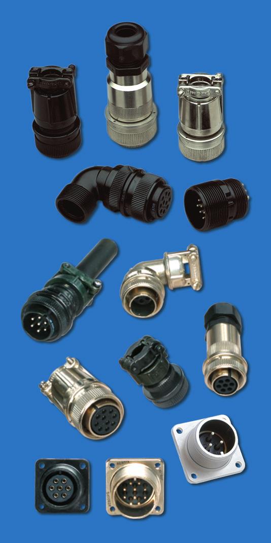
3 mphenol eries industrial application threaded style connector ed eries wall mounting receptacle box mounting receptacle line receptacle straight plug ed onnectors with O igh mperage ontacts esigned with the industrial user in mind, for widely diverse applications such as mass transportation, automo tive, heavy equipment and geophysical industries, and for the entertainment/ lighting industries, the new eries of onnectors offer the following features: ugged aluminum shells urability and reliability nvironmentally acceptable shell plating options - onductive and non-conductive ingle key/keyway shell polarization ive shell styles in sizes 10 to 40 ed coupling arious backshells esilient inserts - Outstanding moisture barrier igh dielectric strength igh resistance to vibration Over 275 insert patterns available lternate insert positioning achined contacts - aximum corrosion resistance aximum current capacity ow millivolt drop older and crimp contacts - silver plated or optional gold plating eneral duty and environmental versions 55 to +125 operating temp. range tandard application tools mphe-ower onnectors - ed onnectors with O contacts are also available. hese are high amperage capability connectors designed for the most demanding industrial and transportation applications. he O contact will handle 50% to 150% higher amperages than standard contacts (size dependent). urrent mphe-ower lines support from 35 to 500 continuous duty. O contacts are available in size 12 (35 amps), size 8 (70 amps), size 4 (120 amps), and size 0 (250 amps). ee page 31 for more information. ote: he previous - ayonet series is replaced by the newer - everse ayonet series. or availability of the -, consult mphenol Industrial Operations. or information on - everse ayonet series connectors see mphenol catalog I-4. o ompliant options available. 1
4 ed wall mounting receptacle X ( )00* ( )00* ¹ ² ¹ X ( )00( )* 4 oles ( )00* ( )00* * o complete order number, see how to order, page 59. Inches in 1 ex ia X ax hell ull lats O.. ize lass ax ax ax.000 ax ef ef ef ±.005 ± able U / / U / / U / / U / / U / / U / / U / / U / / U / / U / / U / / U / / U / / U / / U / / in 1 ex ia X ax hell ull lats +.10 O.. ize.25 ax ax ax.00 ax ef ef ef ±.13 ± able / / / / / / / / / / / / / / / / / / / / / / / / / / / / / / ll dimensions for reference only. illimeters 2
5 ed line receptacle X ¹ ( )01* ( )01* ² ¹ X ( )01( )* ( )01* ( )01* * o complete order number, see how to order, page 59. Inches in 1 X ax hell ull 1 2 exlats O.. ize lass 2 ax ax ax ax ef ef ef able U / / U / / U / / U / / U / / U / / U / / U / / U / / U / / U / / U / / U / / U / / U / / in 1 X ax hell ull 1 2 ex lats O.. ize ax ax ax ax ef ef ef able / / / / / / / / / / / / / / / / / / / / / / / / / / / / / / ll dimensions for reference only. illimeters 3
6 ed box mounting receptacle 4 oles ( )02* ( )02* * o complete order number, see how to order, page 59. Inches in ia ia hell ull ize lass ±.005 ± ax** U U U U U U U U U in ia ia hell ull ize ±.13 ± ax** ** Increase dimension by.312 for size 0 contact only. illimeters ll dimensions for reference only. 4
7 ed straight plug ¹ ¹ X Q ( )06 ( )* ( )06* ( )06* ² X ³ ( )05* ( )05* ( )06* ( )06* * o complete order number, see how to order, page 59. Inches 1 ex X ax hell lats Q lated O.. ize lass 2 ± ax ax ax ax ax ef ef ef ax lass 2 able ± U / / U U / / U U / / U U / / U U / / U U / / U U / / U U / / U U / / U U / / U U / / U U / / U U / / U U / / U U / / U ex X ax hell lats Q O.. ize ± ax ax ax ax ax ef ef ef ax able ± / / / / / / / / / / / / / / / / / / / / / / / / / / / / / / ll dimensions for reference only. illimeters 5
8 ed 90 degree plug Q ¹ Q U U¹ X ( )08* X ( )08* * o complete order number, see how to order, page 59. Inches hell 1 Q ia U U 1 X ax ize lass 2 ax ax ax ax ax ax O.. able U U U U U U U U hell 1 Q ia U U 1 X ax ize ax ax ax ax ax ax O.. able ll dimensions for reference only. illimeters 6


9 mphenol tandard ylindrical onnectors I II edium to heavy weight cylindrical urable, field-proven design nvironmental resistant esilient inserts Operating voltage to 3000 () at sea level ed couplings ingle key/keyway shell polarization -, - -/ - UO OIO ive shell styles ineteen shell sizes 305 contact arrangements from 1 to 104 circuits older or crimp contacts, sizes 16-0 accepting 22-0 W. ive class designations lternate insert positioning ermetic configurations available connectors meet the latest performance require ments of hese connectors represent wellproven electrical capability at an acceptable cost for most equipment where durability is important features threaded couplings and single key/keyway polarization, representing maximum simplicity in design. pplications include military ground support equipment, ordnance and shipboard installations. mphenol Industrial Operations manufactures five classes of connectors to meet different requirements. lass designations and brief descriptions are listed below. olid hell for general, non-environmental applications. ressurized for use on pressurized bulkheads or pressure barriers; limits air leakage regardless of type and class of plug mated with them. / nvironmental esisting with train elief designed for applications where the connector will be exposed to moisture, vibration, and rapid changes in pressure and temperature. ightweight nvironmental esisting shorter in length and lighter in weight than the and classes, the - offers a high degree of reliability under adverse conditions: recommended for new design applications. nvironmental lasses and are updated to and produced in strict accordance to lasses, and are still produced, but are no longer listed on the qualified products database (Q). 7


10 /tandard - and - wall mounting receptacle inline cable receptacle connecting plug box mounting receptacle - and - - and - class connectors perform many of the vital functions in powering, testing and ground support systems. lass applications include communications equipment, computers and shipboard installations where mechanical forces and physical parameters are not subject to extreme or rapid environmental changes. lass connectors are most frequently used on pressurized bulkheads or pressure barriers at elevated altitudes or maritime applications. ir leakage is limited to one cubic inch per hour at a pressure differential of 30 lbs. per square inch. hells: hell components are fabricated from high grade aluminum alloy. lectrically conductive cadmium plate finish with an olive drab chromate after-treat offers corrosion resistance. ontacts: ontacts are solder with pre-filled solder cups. ins and sockets are machined from copper alloy with a silver plated finish. ize 16 and 12 socket contacts incor porate a closed entry design. efer to page 54 for additional contact information. Inserts: Inserts are resilient neoprene, offering high dielectric strength, high arc resistance and resistance to vibration. straight plug 90 degree plug 8
11 /tandard 3100 or wall mounting receptacle 4 oles o complete order number, see how to order pg. 59. or solder well data, see page 29. hell ize lass 2 in ull ± ±.005 ±.031 ia lass U U U U U U U U U U U U U U U U.641* * * * * * U * U U.500* 44*** U U.751** 48*** U U.751** * Increase dimension by.312 for size 0 contact only. ** Increase dimension by.062 for size 0 contact only. *** vailable in proprietary version only ±
12 /tandard 3101 inline receptacle o complete order number, see how to order pg. 59. or solder well data, see page 29. hell ize lass 2 in. ull ±.030 ia. ax. lass 2 ± U U U U U U U U U U U U U U 1.532* * * * * * U * U U 1.532* 44*** U U 1.782** * Increase dimension by.312 for size 0 contact only. ** Increase dimension by.062 for size 0 contact only. *** vailable in proprietary version only. 10
13 /tandard 3102 or box mounting receptacle 4 oles o complete order number, see how to order pg. 59. or solder well data, see page 29. hell ize lass 2 in ull ia ±.005 ±.031 ia U U U U U U U * * * * * U * U * 44*** U ** 48*** U ** * Increase dimension by.312 for size 0 contact only. ** Increase dimension by.062 for size 0 contact only. *** vailable in proprietary version only ±
14 /tandard 3106 straight plug Q o complete order number, see how to order pg. 59. or solder well data, see page 29. ll lockwire holes are.045 dia. min. hell ize lass 2 ±.005 ±.030 Q ia. ax. lass 2 ± U U U U U U U U U U U U U U.812* * * * * * U * U U.812* 44*** U U 1.063** 48*** U U 1.063** * Increase dimension by.312 for size 0 contact only. ** Increase dimension by.062 for size 0 contact only. *** vailable in proprietary version only
15 /tandard degree plug Q U W o complete order number, see how to order pg. 59. or solder well data, see page 29. ll lockwire holes are.045 dia. min. hell ize lass 2 ±.005 ax. Q ia. ax. U ax. lass 2 W ± U U U U U U U U U U U U U U * * * * * * U * U U * * Increase dimension by.312 for size 0 contact only. 13


16 /tandard -/ wall mounting receptacle inline cable receptacle connecting plug box mounting receptacle - & lass connectors satisfy all the performance requirements of lass, environmental is also produced, but is no longer listed on the qualified products listing (Q). hese connectors are recommended for conditions where vibration, moisture, pressure and/or temperature are extreme. train relief is supplied on most shell sizes. hells: hell components are fabricated from high grade aluminum alloy. he standard hardware plating is electrically conductive cadmium plated finish with an olive drab chromate after-treatment for corrosion resistance. ontacts: ontacts are silver plated copper alloy for maximum corrosion resistance, maximum current carrying capacity and low millivolt drop. ize 16 and 12 socket contacts incorporate a closed entry design. efer to page 54 for additional contact information. Inserts: esilient neoprene inserts provide an outstanding moisture barrier, high dielectric strength, and resistance to vibration. ither pin or socket insert can be pressurized. train elief lamp: train relief clamps minimize tension at the solder well connection and provide a positive mechanical moisture seal. omplete field serviceability is possible with the strain relief clamp. straight plug 90 degree plug 14
17 /tandard 3100/ wall mounting receptacle XX 4 oles o complete order number, see how to order pg. 59. or solder well data, see page 29. hell ize lass 2 in. ull ax ax. ±.005 ±.010 ia * ax. XX in. able learance U U U U U U U U U U U U U U U * Increase dimension by.312 for size 0 contact only. 15
18 /tandard 3101/ inline receptacle XX o complete order number, see how to order pg. 59. or solder well data, see page 29. hell ize lass 2 in. ull ax. ax. * ax. XX in. able learance U U U U U U U U U U U U U U U * Increase dimension by.312 for size 0 contact only. 16
19 /tandard 3102 box mounting receptacle 4 oles o complete order number, see how to order pg. 59. or solder well data, see page 29. hell ize lass 2 in. ull ia ±.005 ±.031 ia U U U U U U U * * * * * * U * U * * Increase dimension by.312 for size 0 contact only. 17
20 /tandard 3106/ straight plug Q XX o complete order number, see how to order pg. 59. or solder well data, see page 29. ll lockwire holes are.045 dia. min. hell ize lass 2 ±.005 ax. ax. Q ax. * ±.045 XX in. able learance U U U U U U U U U U U U U U U * Increase dimension by.312 for size 0 contact only. 18
21 /tandard degree plug Q U Y o complete order number, see how to order pg. 59. or solder well data, see page 29. ll lockwire holes are.045 dia. min. hell ize lass 2 ±.005 ax. ax. Q ia. ax. U ax. Y lass 2 ± U U U U U U U * * * * * * U * U * * Increase dimension by.312 for size 0 contact only. 19


22 /tandard - wall mounting receptacle inline receptacle cable connecting plug box mounting receptacle box mounting receptacle - pecification requirements for greater reliability in a shorter, lighter weight environmental resistant connector led to the design of the -. lass connectors satisfy all the performance requirements of his low profile assembly was attained by moving the axial compression nut and grommet assembly forward and flush with the rear of the insert. he neoprene grom met, with its low coefficient of friction, assures easier threading of wire bundles and quicker assembly and ser viceability of the unit. olded webs in each wire hole insure a moisture barrier around each wire. he addition of an O ring at the main joint of all 3106 plugs provide a main joint seal supplementary to the interfacial seal, thus insuring a higher degree of reliability when connector halves from different sources are employed. hells: hell components are fabricated from high grade aluminum alloy. ll components have the standard electrically conductive cadmium plated finish with an olive drab chromate after-treatment for corrosion resistance. ontacts: ontacts are machined from copper alloy for maximum corrosion resistance, maximum current carrying capacity and low millivolt drop. efer to page 54 for additional contact information. Inserts: esilient neoprene inserts provide an outstanding moisture barrier, maximum vibration resistance and high dielectric strength. ither pin or socket insert can be pressurized. straight plug 20
23 /tandard 3100 wall mounting receptacle 4 oles Y o complete order number, see how to order pg. 59. or solder well data, see page 29. ll lockwire holes are.045 dia. min. hell ize lass 2 in. ull ia. ax ax ia. ax. ±.005 ±.031 Y lass U U U U U U U * * * * * * U * U * * Increase dimension by.312 for size 0 contact only. ia
24 /tandard 3101 inline receptacle Y o complete order number, see how to order pg. 59. or solder well data, see page 29. ll lockwire holes are.045 dia. min. hell ize lass 2 in. ull ia. ax. ia. ax. ax. Y lass 2 ± U U U U U U U * * * * * * U * U * * Increase dimension by.312 for size 0 contact only. 22
25 /tandard 3102 box mounting receptacle 4 oles o complete order number, see how to order pg. 59. or solder well data, see page 29. hell ize lass 2 in. ull ia ±.005 ±.031 ia U U U U U U U * * * * * * U * U * * Increase dimension by.312 for size 0 contact only. 23
26 /tandard 3106 straight plug Q Y o complete order number, see how to order pg. 59. or solder well data, see page 29. ll lockwire holes are.045 dia. min. hell ize lass 2 ia. ax. ±.005 ax. ia. ax. Q ia. ax. Y lass 2 ± U U U U U U U * * * * * * U * U * * Increase dimension by.312 for size 0 contact only. 24
27 eries/ insert availability Insert ervice otal ontact ize rrangement ating ontacts Inst Inst Inst Inst /Inst Inst Inst /Inst Insert ervice otal ontact ize rrangement ating ontacts / Inst / Inst Inst Inst * * * / / / / / 8 8 * rimp contacts accommodate wire the same size as the contact as well as wire of the next smaller, even size. rrangements identified with an asterisk (*) are exceptions. ee insert arrangement drawings on pages for application wire size. 25
28 eries/ insert availability, cont. ontact ize Insert otal rrange ervice on- oax** ment ating tacts 4/0 2/ / / / / / / 8 8* * / / Inst i-olt * Inst * * Inst Inst / * rimp contacts accommodate wire the same size as the contact as well as wire of the next smaller, even size. rrangements identified with an asterisk (*) are exceptions. ee insert arrangement drawings on pages for application wire size. ontact ize Insert otal rrange ervice on- oax** ment ating tacts 4/0 2/ / // / // ///Inst // oax * * Y / / Inst./ /// / Inst Inst./
29 eries/ insert availability, cont. ontact ize Insert otal rrange ervice on- oax** ment ating tacts 4/0 2/ * oax oax oax Inst oax / / / * * * oax oax oax * * ontact ize Insert otal rrange ervice on- oax** ment ating tacts 4/0 2/ oax / 35 35* * oax oax * Inst U * rimp contacts accommodate wire the same size as the contact as well as wire of the next smaller, even size. rrangements identified with an asterisk (*) are exceptions. ee insert arrangement drawings on pages for application wire size. 27
30 eries/ insert alternate positioning o avoid cross-plugging problems in applications requiring the use of more than one connector of the same size and arrangement, alternate rotations are available as indicated in the accompanying charts. s shown in the diagram below, the front face of the pin insert is rotated within the shell in a clockwise direction from the normal shell key. he socket insert would be rotated counterclockwise the same number of degrees in respect to the normal shell key. osition W osition X osition Y osition iew looking into front face of pin insert or rear of socket insert. Insert egrees rrangement W X Y Insert egrees rrangement W X Y he following insert arrangements have the same alternate insert rotations for W, X, Y and, which are: egrees W X Y U Insert egrees rrangement W X Y Y art umb or or
31 eries/ solder contacts achined copper alloy contacts in a full range of sizes, with closed entry socket design in the size 12 and 16 contacts. heavy silver-plated finish is deposited on all solder contacts for maximum corrosion resistance, maximum current car rying capacity and low millivolt drop. O O* in/ ating nd Wire arrel llowable est urrent** er ocket ize ize Wire ize mps in hort ocket in ong ocket in ocket in ocket in ocket 6 60 in ocket * older Wells illed ** ontact ratings as stated are test ratings only. he connector may not withstand full rated current through all contacts continuously. lease note that the electrical data given is not an establishment of electrical safety factors. his is left entirely in the designer s hands as he can best determine which peak voltage, switching surges, transients, etc. can be expected in a particular circuit. he 10, 12, 14 and 16 connectors require short contacts. O I I ecommended ffective Operating oltage* reepage echanical ervice at ea evel istance pacing ating () om. om. Inst / /8 1/ /16 1/ /4 3/ /16 1/ /16 * he values listed in able I represent operating val ues which include a generous safety factor. It may be necessary for some applications to exceed the operating voltages listed here. If this is necessary, designers will find able II useful for determining the degree to which the recommended values of able I can be exceeded. IU O I** ominal tandard ea ressure ltitude ressure ltitude istance evel onditions 50,000 eet 70,000 eet inimum inimum inimum lashover est lashover est lashover est ervice oltage oltage oltage oltage oltage oltage ating irspace reepage () () () () () () Inst. 1/32 1/ /16 1/ /8 3/ /16 1/ /4 5/ / ot corrected for changes in density due to variations in temperature ** o attempt has been made to recommend operating voltages. he designer must determine his own oper ating voltage by the application of a safety factor to the above derating chart to compensate for circuit tran sients, surges, etc. 29
32 eries/ crimp contacts achined from copper alloys and silver-plated for maximum corrosion resistance, with a minimum millivolt drop and a maximum current carrying capacity, the size 16 and 12 socket contacts are of the closed entry design. rimp contacts are available for all insert arrangements and are identified with a mphenol proprietary number. old plated contacts are also available. (ee how to order on page 59). I O* art in/ ating nd Wire arrel llowable equired Wire est urrent** umber ocket ize ize Wire ize dapter leeve mps in hort ocket * in ong ocket * in ocket in ocket 10* in ocket 6* in ocket 2* * When using wire adapter sleeve shown ** ontact ratings as stated are test ratings only. he connector may not withstand full rated current through all contacts continuously. lease note that the electrical data given is not an establishment of electrical safety factors. his is left entirely in the designer s hands as he can best determine which peak voltage, switching surges, transients, etc. can be expected in a particular circuit. he 10, 12, 14 and 16 connectors require short contacts. dditional contact variations are available; consult mphenol, idney Y for information. O I I ecommended ffective Operating oltage* reepage echanical ervice at ea evel istance pacing ating () om. om. Inst / /8 1/ /16 1/ /4 3/ /16 1/ /16 IU O I** ominal tandard ea ressure ltitude ressure ltitude istance evel onditions 50,000 eet 70,000 eet inimum inimum inimum lashover est lashover est lashover est ervice oltage oltage oltage oltage oltage oltage ating irspace reepage () () () () () () Inst. 1/32 1/ /16 1/ /8 3/ /16 1/ /4 5/ / ot corrected for changes in density due to variations in temperature. ** o attempt has been made to recommend operating voltages. he designer must determine his own oper ating voltage by the application of a safety factor to the above derating chart to compensate for circuit tran sients, surges, etc. 30

33 O echnology O echnology dvantages O twisted grid configuration allows for 50% more current to pass through the same size pin, while providing increased reliability, ampacity and cycle durability as well as lower insertion force, -rise and voltage drop. I IIIY O erating hart emperature vs. urrent ased on single conductors in free air. Wire cross-section same size as pin contact crosssectional area. Unique O design and construction technology create an electrical contact interface that exceeds typical interconnect requirements. pplications in aerospace, medical, industrial, automotive, mining, offshore, and other harsh environments depend on the high reliability of mphenol s O technology. OW O /IO O he hyperbolic lamella socket contact construction distributes normal forces over a high percentage of the mating pin surface. his creates a smooth, even engagement effort. his force distribution also contributes to excellent performance in vibration applications with resistance to typical fretting corrosion. OW O I he large interface area between the socket lamella and pin surface result in very low contact resistance, enabling the O contacts high current ratings compared to traditional power contact designs. I I Y UIIY O contacts with typical silver plating finishes have demonstrated survival of 20,000 mating cycles. pecialized plating and contact lubricants can extend cycle life to 200,000 matings or higher. ven with continuous exposure to harsh environmental abuse (salt, sand, and high humidity), O contacts have been tested to maintain low contact resistance beyond 10,000 mating cycles. O ocket able O art umber ilver ocket ontact old ating ize I O Wire arrell ize llowable Wire ize * 4 6* 0 2* equired Wire dapter leeve est urrent** 35 *** 70 *** 120 *** 250 *** * When using wire adapter sleeve shown ** ontact ratings as stated are test ratings only. he connector may not withstand full rated current through all contacts continuously. lease note that the electrical data given is not an establishment of electrical safety factors. his is left entirely in the designer s hands as he can best determine which peak voltage, switching surges, transients, etc. can be expected in a particular circuit. *** onsult mphenol Industrial for test current at these wire sizes. 31
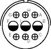
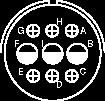
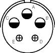
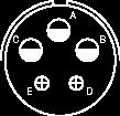
34 eries/ contact arrangements front face of pin insert or rear face of socket insert illustrated ront of ront of ocket Insert ocket Insert Insert rrangement ervice ating Inst. umber of ontacts ontact ize Insert rrangement ervice ating Inst. Inst. Inst. umber of ontacts otation of 14-2 ontact ize otation of 14-7 Insert rrangement ervice ating umber of ontacts ontact ize Insert rrangement ervice ating umber of ontacts ontact ize O


35 eries/ contact arrangements front face of pin insert or rear face of socket insert illustrated Insert rrangement ervice ating,,, = ; bal. = Inst. umber of ontacts * 4 10 ontact ize Insert rrangement ervice ating umber of ontacts ontact ize Insert rrangement ervice ating Inst. umber of ontacts ontact ize Insert rrangement ervice ating Inst. umber of ontacts 4** ontact ize * = Iron: = onstantan **, = Iron;, = onstantan 33 O


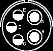
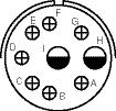
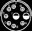
36 eries/ contact arrangements front face of pin insert or rear face of socket insert illustrated I otation 110 otation 260 otation of 18-1 of of Insert rrangement ervice ating,,, = ; al. = Inst. umber of ontacts ontact ize Insert rrangement ervice ating,,, = ;,,, = Inst. = ; al. = Inst. umber of ontacts ontact ize Insert rrangement ervice ating umber of ontacts ontact ize O


37 eries/ contact arrangements front face of pin insert or rear face of socket insert illustrated Insert rrangement ervice ating umber of ontacts ontact ize otation 250 otation of of Insert rrangement ervice ating Inst. Inst. umber of ontacts * ontact ize Insert rrangement ervice ating = ; al. = umber of ontacts 7* 5 5 3* 1 5 7* 1* ontact ize 12 for #14 or 16 wire for #10 or 12 wire for #10 wire for #16 wire 35 O


38 eries/ contact arrangements front face of pin insert or rear face of socket insert illustrated Insert rrangement ervice ating umber of ontacts ontact ize Insert rrangement ervice ating = ;,,, = umber of ontacts ontact ize U Insert rrangement ervice ating = ;,,,, = = ; al. =,,,, = ;,, = umber of ontacts ontact ize O


39 eries/ contact arrangements front face of pin insert or rear face of socket insert illustrated Insert rrangement ervice ating =; al = umber of ontacts ontact ize Insert rrangement ervice ating,, = ;,, = = ; al. =,,, = ;,, = umber of ontacts ontact ize Insert rrangement ervice ating = ; al. = ** = ; al. = umber of ontacts * 8 5 3* ontact ize for #14 or 16 wire for #10 or 12 wire * olderless **,,, = Iron,,, = onstantan O
40 38 eries/ contact arrangements front face of pin insert or rear face of socket insert illustrated O Insert rrangement ervice ating,, = ; al. = umber of ontacts ontact ize I O Insert rrangement ervice ating,,, = ;,, = umber of ontacts ontact ize I Insert rrangement ervice ating umber of ontacts ontact ize
41 eries/ contact arrangements front face of pin insert or rear face of socket insert illustrated Q U W X Y Insert rrangement ervice ating Inst. i-olt umber of ontacts * 1 5* ontact ize 16 16, for #10 or 12 wire 12 8,, for #8 wire Insert rrangement ervice ating umber of ontacts * ontact ize for #10 or 12 wire U 90 Q U W X Insert rrangement ervice ating Inst. Inst. umber of ontacts 19 2* 5* ontact ize for #10 or 12 wire 8 8 for #16 wire O
42 eries/ contact arrangements front face of pin insert or rear face of socket insert illustrated U Q U W X Y a Insert rrangement ervice ating Inst.,, = ; al. = umber of ontacts ontact ize (oax) /U or -174/U Insert rrangement ervice ating,, = ; al. = umber of ontacts ontact ize U W X I a b U Y d X W Insert rrangement ervice ating, = ; = ; al. = = ; al. = umber of ontacts ontact ize O
43 41 eries/ contact arrangements front face of pin insert or rear face of socket insert illustrated O Insert rrangement ervice ating = ;,, = ; to = umber of ontacts ontact ize Insert rrangement ervice ating = ;,,,, = ;, = ; al = Inst., = ;, = ; al.= umber of ontacts ontact ize U W X a b c d e f g h j k m n p r s Insert rrangement ervice ating umber of ontacts ontact ize U 100 U W X Y a b d W X Y U a b c d e f g h j k m l Q U 100 otation of 28-12
44 42 eries/ contact arrangements front face of pin insert or rear face of socket insert illustrated O Insert rrangement ervice ating umber of ontacts * 4* 3* 9* 7* ontact ize (oax) -59 /U for #10 wire 16 8 for #10 wire I Insert rrangement Y ervice ating umber of ontacts ontact ize O Insert rrangement ervice ating = ;,,, =,,, = ; al. = umber of ontacts
45 43 eries/ contact arrangements front face of pin insert or rear face of socket insert illustrated O Insert rrangement ervice ating, = ; = ;, = ;, =,,,, = ; al. = umber of ontacts ontact ize I O U W X Y Insert rrangement ervice ating umber of ontacts ontact ize otation of I O U W X O U W I X I O U W X Y a b c d e I O U W X Y a b c d e f g h j k Insert rrangement ervice ating,, h, j = Inst.; al = umber of ontacts ontact ize
46 eries/ contact arrangements front face of pin insert or rear face of socket insert illustrated O U W X Y a b m c d e g h j k n p q s t u v x y w z f r U W X Y a b c d f g h i j k m n p q r s t u v w x y z Insert rrangement ervice ating Inst. umber of ontacts ontact ize a b c Y j k d X i m f U q r W h n g p s v t u w c d e Y a b U W X O I 100 otation Insert rrangement ervice ating t, u = ; al = Inst. ** umber of ontacts ontact ize for #10 wire 12 0 (oax) -71/U Y X W p n w m U k v j U i q h s g t a b c d f a Y X W U I O U W X Insert rrangement ervice ating ** umber of ontacts ontact ize 4 (oax) -161/U 16 8 (oax) -161/U 16 8 (oax) (oax) or -179/U -124/U -124/U16 44 O
47 eries/ contact arrangements front face of pin insert or rear face of socket insert illustrated O U W X Y a b c d e f g h j k m n p q r s t u v w x y z Q Insert rrangement ervice ating Inst. 8, 9 = umber of ontacts ontact ize (oax) -58 /U (oax) -180 /U Q O U W X Y a b c d e f g h j k n q m p r s t u v w x y z Insert rrangement ervice ating umber of ontacts ontact ize I O U W Insert rrangement ervice ating = ;, = umber of ontacts ontact ize O
48 eries/ contact arrangements front face of pin insert or rear face of socket insert illustrated I O U W X Y a b c h n r d j x u e f g k t p v w z y s m I O W Y U a X b c d e f g k h j n p m r s u t v w x z y d e f U a Y W b c X I O Insert rrangement ervice ating umber of ontacts ontact ize O Q U W X Y a b c d e f g h j k m n p q r s t u v w x y z 100 O Q U W X Y a b c d e f g h j k m n p q r s t u v w x y z 110 O Q U W X Y a b c d e f g h j k q m n p r s t u v w x y z Q 100 otation 110 otation of of Insert rrangement ervice ating,, Q = ; al. = umber of ontacts ontact ize I Q Q d c k j b h a U e m f W g X Y 100 I O U W X Y a b c d e f g h j t k n p m u w v r s x y z 100 otation of 36-7 Insert rrangement ervice ating = ; al. = umber of ontacts O
49 eries/ contact arrangements front face of pin insert or rear face of socket insert illustrated 110 I O U W X Y a b c e d f g m h j t k n u v p w r s x z y 110 otation 100 otation of 36-7 of 36-9 Insert rrangement ervice ating umber of ontacts ontact ize d e f b c a Y U W X O I U W X Y a b c d e h j f g k m U W X Y a b c d f g h i W X Y k a r s b t m c n d j k m n p q r s t u v w x y z U j i q h p f g Insert rrangement ervice ating umber of ontacts ontact ize W X U Y k j i a b h r q s t m c p n d f g U W X Y a b c d f g h i j k m n p q r s t u v w x y z I O U W X Y a b c h n r d j x u e f g k t p v w z y s m Insert rrangement ervice ating ** umber of ontacts ontact ize 16 8 for #6 wire for #10 wire for #10 wire 47 O
50 eries/ contact arrangements front face of pin insert or rear face of socket insert illustrated U W X Y a b c d f g h i j k m n p q r s t u v w x y z Insert rrangement ervice ating umber of ontacts ontact ize 0 (oax) -11/U, 0 (oax) -59/U, -62/U /U or -13/U or -71/U Insert rrangement ervice ating umber of ontacts ontact ize 4 (oax) -62/U 16 8 (oax) -187/U 16 for #14 wire Insert rrangement ervice ating umber of ontacts ontact ize O
51 eries/ contact arrangements front face of pin insert or rear face of socket insert illustrated Insert rrangement ervice ating umber of ontacts ontact ize for #10 wire 4 (oax) -58/U Q d c k b j h a U e m f g Y W X Insert rrangement ervice ating = ; al. = umber of ontacts ontact ize 16 for #12 wire 4/ z d e y Q f x g O w Y h v c X j b a u W U k t m s n r p q I O U W X Y a b c d e Insert rrangement ervice ating umber of ontacts ontact ize O /0 4/0 49
52 eries/ contact arrangements front face of pin insert or rear face of socket insert illustrated I O Q U W X b c d e f Y a g h i I O Q j k r l p t m q u n s o Y W c a b X U Insert rrangement ervice ating umber of ontacts ontact ize U W X Y a b c d f g q h i j k m n p r s t u v w x y z U W X Y U Insert rrangement ervice ating umber of ontacts ontact ize Insert rrangement ervice ating umber of ontacts ontact ize O
53 eries/ contact arrangements front face of pin insert or rear face of socket insert illustrated h g p f d n c m b a i U j q k W X Y Insert rrangement ervice ating umber of ontacts ontact ize 16 for #14 wire (oax) -124/U 0 (oax) -63/U W U X Insert rrangement ervice ating umber of ontacts ontact ize 16 4 (oax) -59/U Insert rrangement ervice ating umber of ontacts ontact ize 16 4 (oax) -9/U (oax) -62/U 0 (oax) -9/U 51 O
54 eries/ contact arrangements front face of pin insert or rear face of socket insert illustrated Insert rrangement ervice ating umber of ontacts ontact ize for #14 wire Insert rrangement ervice ating umber of ontacts ontact ize for #14 wire 0 (oax) -115/U Insert rrangement ervice ating umber of ontacts ontact ize O
55 eries/ contact arrangements front face of pin insert or rear face of socket insert illustrated Insert rrangement ervice ating Inst. umber of ontacts ontact ize 4/ Insert rrangement U 40- ervice ating umber of ontacts ontact ize /0 O /0 4/0 53
56 eries - hermocouple contact availability complete line of cylindrical connectors containing thermocouple insert arrangements is available. he contact layout for a particular arrangement will be found in either the /tandard contact arrangement section, pages 26-37, 32-53, or the pecial contact arrangement section, pages ll thermocouple contact layouts may contain either iron, alumel, chromel, constantan, standard (copper) or brass (dummy) contacts. ee the thermocouple tabulations on the following pages. he following abbreviations are used in the contact material column in the charts that follow. lso, thermocouple contacts are color coded as shown. (his identification is made by means of small dots of stain on the solder well end of the contact). bbreviation aterial olor ode Ir. Iron lack on. onstantan Yellow u. opper lloy / h. hromel White l. lumel reen ummy rass / ontact ize Well Inside ia WI W Well epth older Well arrel Outside ia ± I hromel - lumel II Iron - onstantan O WI Use wire in accordance with I-W-5848 Use wire in accordance with I-W
57 eries - hermocouple contact arrangements hell ize and rrg. imilar to rrg. otal ontacts ontact ize in Insert otation W = Ir.; = on = u.; = on = l.; = h one = Ir.; = on.; = u one = l.; = h.; = u one = l.; = h one = h.; = on one = h.; = l.; = u one = h.; = l one = Ir.; = on one = u.; = on one = u.; = l.; = Ir one, = on.; = h one, = h.; = l. ontact aterial = h.; = l = Ir.; = on = u.; = on one = l.; = h = h.; = l = Ir.; = on one = Ir.; = on one = u.; = on one = h.; = on one = h.; = l = l.; = h , = u.; = l.; = h = Ir.; = on ,, = Ir.;,, = on , = Ir.;, = on = Ir.; = on.;, = u , = l.;, = h = l.; = h.; = u = u.; = on one = l.; = h = l.; = h.; = Ir.; = on.;, = u one, = l.;, = h.; = Ir.; = on one, = on.;, = u one,., = u.;,, = on one = l.; = h.; alance = u = h.; = on.;, = u one = on.; = h.; = u one, = h.;, = l one,, = u.; = on one = on.; = u one, = u.; = l.; = h. 55
58 eries - hermocouple contact arrangements hell ize and rrg. imilar to rrg. otal ontacts ontact ize in Insert otation W one, = h.;, = l one, = u.;, = on one, = l.;, = h one, = l.;, = h one = h.; = l. ontact aterial one = h.; = l one = l.; = h.; alance = u one = on.; alance = u = l.; = h = l.; = h.;, = u = l.; = h.; = u = on.; = u one = l.; = u.; = h one = on.;, = u one = l.; = h one = on.; = u one = Ir.;, = on.; = u.;, = ummy one = Ir.; = on.; = h.; = l.; = ummy one, = Ir.;, = on.;, = ummy one, = l.;, = h ,,,, I = Ir.;,,,, = on ,, = l.;,, = h , = Ir.;,, = on.; = u , = l.;,, = h.; = u one, = Ir.;, = on.; = h.; = l one,, = Ir.;,, = on one, = on.;, = u one = Ir.; = on.; alance = u one,,,, I = u.;,,,, = on one,, = u.;,, = on one, = l.;, = h.; = u one = l.; = h.; alance = u one = Ir.; = on.; = h.; = l.; = u one = on.; alance = u one = on.; alance = u one = l.; = h.; alance = u one = h.; = l.; = Ir.; = u.;, = on = Ir.; = on.; = h.; = l ,,, = Ir.;,,, = on = h.; = l.; alance = u ,, = u.; alance = on ,, = l.;,, = h.; = u one = l.; = h.; alance = u. 56
59 eries - hermocouple contact arrangements hell ize and rrg. imilar to rrg. otal ontacts ontact ize in Insert otation W ontact aterial one,,,,,, = Ir.;, I,,,,, = on one = l.; I = h.; alance = u one,,, = on.;,,, = u one,,,,,, = u.;, I,,,,, = on one,,,,,,,, = Ir.;,,,,,,, = on one = l.; = h.; alance = u one,,,,,,, = Ir.;,,,,,,, = on.; = u one = l.; alance = h one = on.; alance = td one,,,, I,, = u.;,,,,,, = on one,,,, I,, = h.;,,,,,, = l one,,,,,,, = l.;,,,,,,, = h.; = u ,,, = Ir.;,,, = on ,,,,,,, = Ir.;,,,,,,, = on.;, U, = u U = l.; = h.; alance = u ,,, = l.;,,, = h ,,,,,, = Ir.;,,,,,, = on ,,,,,, = u.;,,,,,, = on one = l.; U = h.; alance = u one = l.; = h.; alance = u one = l.; = h.; alance = u one,,, = Ir.;,,, = on one = l.;,,, = u.; = h.; = Ir.; = on one W = on.; alance = u one,,,,,,, = u.;,, = Ir.;,, = on one,,,,,,,,, = on.; alance = u one,, = on.;, = u = l.; = h.; alance = u ,,,, Y, W,,,, U,, = h.; alance = l one,,, = Ir.;,,, = on.;, = h.;, U = l.; alance = u one,,,,,,,,, U, W, Y = u.;,,,, Q,,,,,, X, = on one,,,,,,, = Ir.;,,,,,,, = on one = on.; alance = u one,,,, I,,,, = u.;,,,,,, O = on , = l.;, = h.; alance = u ,,,,, = l.;,,,,, = h.;, = u ,,,, m, r, n, a,,,, X, k, h,,,, d = Ir.; alance = on ,,,, = l.;,,,, = h.; alance = u one, d = l.;, j = h.;,,,,,,,,,,,,,, W, X, Y, = on.; alance = u one,,,,,,,,, = Ir.; X, = l.;,,,,,,,, U, W = on.; Y, a = h.; b, d = u one U = on.; alance = u = l.; U = h.; alance = u. 57
60 eries - hermocouple contact arrangements ontact in Insert hell ize imilar to otal ize and rrg. rrg. ontacts otation W ontact aterial one = l.; = h.; alance = u one = l.; = h.; alance = u one = on.; alance = u one,,,, n, s = Ir.;,,, f, g, r = on.;,,, b, e, j = l.;,,, X, h, k = h.; alance = u = h.; = l.; alance = u , = h.; O, = l.; alance = u u, v, w = l.; x, y, z = h.; alance = u one,,,,,,,,,,, X, b, d, f, h, k, q, n, m, u, w, y = on.; alance = u one W = l.; f = h. alance = u one = l.; = h.; alance = u one,,,,,,,,,,,, f, X, Y, h, j, c = on.; alance = u one,,, = l.;,, = h.; alance = u * one v, g = Ir.; p, y, c = on. x = h.; alance = u * one,,,,,,,, U, W, Y, a, c, f, h, j, m, p, r, t, v, x, z,,,,,,,,, U, W, Y,,,,,,,,, U = Ir.; alance = on * one = h.; = on.; alance = u * one 55, 60 = Ir.; 57, 58, 59 = on.; 56 = h.; alance = u * one 50, 51 = Ir.; 27, 28, 29, 31, 32, 34, 36, 37 = on.; 25, 39, 40, 41 = l.; 43, 44, 45, 46, 47, 48, 49, 52, 53, 54 = h.; alance = u one,,,,,, etc. = u.;,,,,,, etc. = on. * mphenol arrangement 58

61 eries how to order o more easily illustrate ordering procedure, part number X(025) is shown as follows: X (025) designates mphenol Industrial eries ed onnectors 2. designates rimp ontacts designates older ontacts 3. designates low smoke zero halogen inserts and grommets Omit for standard resilient inserts and grommets. 4. hell tyle 00 - Wall ounting eceptacle 01 - ine eceptacle 02 - ox ounting eceptacle 05 - traight lug 06 - traight lug with hardware degree lug 5. lass or - eneral duty connector or - nvironmental connector for a wire bundle or - nvironmental connector for jacketed cable 6. hell size and insert arrangement ee insert availability on pages ontact type - in contacts - ocket contacts - O crimp socket contacts (see page 31) sk for rochure -391 for mphe-ower onnectors with O echnology. 8. lternate insert rotation W, X, Y, designates that the insert is rotated in its shell from a normal position. o letter required for normal (no rotation) position. ee page 28 for availability. 9. ariations o ompliant (072) - ray zinc nickel finish (023) - lectroless nickel finish (025) - lack zinc alloy finish (96) - lack hard-coat anodize (30) - old plated contacts (116) - on-pre-tinned solder contacts (472) - lack zinc alloy finish and solder contacts less pre-filled cup (548) - lectroless nickel finish and solder contacts less pre-filled cup (724) - ray zinc nickel finish and solder contacts less pre-filled cup 59 or further o ompliant support, contact mphenol Industrial Operations or call
62 /tandard how to order (older ontacts) W onnector ype designates ilitary tandard 2. onnector tyle 3100 wall mounting receptacle 3101 cable connecting receptacle 3102 box mounting receptacle 3106 straight plug plug 3. ervice lass solid shell for general, non-environmental applications solid shell for pressurized applications (3102 only) environmental resisting environmental resisting with strain relief lightweight environmental resisting 4., 5. hell size and insert arrangement - see tables, pages ontact ypes designates pin contact designates socket contact 7. Insert otation W, X, Y, or designate that insert is rotated in its shell from normal position. o letter required for normal (no rotation) position. 60

63 eries/ accessories , sealing gaskets, sealing plugs, sealing ranges I.031 ±.010 I.020 ±.004 II he mphenol plain flat gasket of synthetic rubber material is provided to take complete advantage of waterproof and pressure sealing features. It is for use with the flange mounted receptacle. his flat gasket is provided to give the maximum in connector performance. Its special feature is in providing the maximum radio shielding under difficult conditions of high receiver sensitivity and low signal strength while retaining the sealing characteristics of the plain gasket. his gasket is for use with the flange mounting 4 O.031 ±.010 OW U his gasket is provided for applications where the major requirement is resistance to the injurious effects of extremely low temperature. ven at temperatures as low as 67 this gasket retains its resiliency and will seal a pressure differential of 30 psi. Installation imensions Order ata Inches illimeters hell lain hielding ow ize ± ±.010 ± ±.25 emperature tyle I U XX1 ealing plugs are used to fill unused holes in multi-holed grommet configurations. I Inches illimeters ontact Wire olor ia ia. Order o. ize ize ode ±.010 ±.005 ±.010 ± 0.2 ± 0.1 ± lue ** *** Yellow ** *** White lue Yellow I O O I ** ±.020 *** ± 0.5 mm ll dimensions for reference only ole ealing ange ize illimeters Inches
64 eries/ ccessories style cable clamp, 3420 sleeve he style cable clamp was designed for use with jacketed cable or wires protected by tubing. oth clamping halves float for maximum strain relief. or unjacketed cable or wires, use corresponding 3420 sleeve. o order clamp with sleeve, add -1 to the 97 - number. wo telescoping sleeves are furnished with shells sizes 24 and larger. hell ize mphenol umber ±.031 ax. ia. in. 10, , , , , leeve art o. mphenol umber ±.005 ±.005 ±.010 ±
65 eries/ ccessories protection caps plug U OIO XX* ssembly umber lass 2 ia pprox. ax U U U U U U U U U U U U U U U OIO XX* ssembly umber lass 2 pprox. ef. ax U U U U U U OIO XX* umber lass 2 ia pprox. ax U U U U U U U U U U U U U * rotective caps are illustrated with sash chains and are available with beaded chains or without chains. Optional terminations are also available. onsult mphenol, idney, Y when ordering. 63
66 eries/ ccessories protection caps receptacle OIO XX* ssembly umber lass 2 ia. in. pprox. ia. ax. ax U U U U U U U U U U U U U OIO XXX* ssembly umber lass 2 ef. pprox. ia. ax. ax U U U U U U U U U U U U OIO XX* umber lass pprox. ia. ax. ax U U U U U U U U U U U U U * rotective caps are illustrated with sash chains and are available with beaded chains or without chains. Optional terminations are also available. onsult mphenol, idney, Y when ordering. ap without chain
67 eries/ dust caps U for external threads 1 hell ize Order umber ia. ominal ia. ± ± U U for internal threads 2 hell ize Order umber ia. in. 2 ±
68 eries/ application tools, torque values When proprietary crimp contacts are employed rather than the standard approved solder contacts, the following application tools are recommended for use. here is a possibility of additional crimping tools other than those included being available at present or in the future for this specific application. omplete instructions for providing reliable crimped wire to contact terminations and inserting proprietary crimp contacts in eries connectors are available in publication OOI rimping ositioner/ ontact ontact Insertion emoval ool urret ize tyle ool ool 22520/1-01 * 16 in & ocket it 22520/1-01 * 12 in & ocket it ** ** 8 in & ocket it ** ** 4 in & ocket in ocket ** ** 0 in & ocket in ocket * Use aniels urret 29-1 or stro ool o. urret ** or appropriate crimp tool and positioner refer to ico rimping ool o. ools used with rbor ress O OQU O OO ize In./b. ax. ize In./b. ax


69 dditional roducts reverse bayonet coupling 5015 type connectors mphenol has replaced the previously available - series with the -. he - is a modification of the family designed for commercial and industrial environments requiring a rugged bayonet style connector, including heavy duty power and signal applications. comprehensive selection of insert arrangements and accessory hardware are available to accommodate heavy-duty, commercial wire and cable. he rugged shell is made from aluminum alloy and plated with a variety of finishes to meet any application. eatures of the - everse ayonet series: Quick positive coupling with audible and tactile indication of full coupling. Intermateable with existing connectors ated 500 couplings minimum. o lockwiring required Inserts available in eoprene material with alternate materials available upon request. ontacts available in gold and silver plating vailable in both crimp and solder terminations umerous finishes available, including cadmium free zinc alloy. ugged construction; aluminum or stainless steel components. mphenol - everse ayonet onnectors sk for mphenol catalog I-4 for further information on - everse ayonet onnectors. everse ayonet onnectors mphenol eries of onnectors are heavy duty, rugged and environmentally resistant, and are the preferred interconnect for the mass transit industry. hey are also used in power generation, petrochemical industries and heavy equipment/geophysical marketplaces. connector utilize and commercial inserts and are intermateable with existing connectors. Other features include: reverse bayonet coupling - quick mating, audible, visual and tactile full mating indicators. U recognized rated to 2000 couplings min. operating temperature range: with eoprene inserts: 55 to +125 with iton** inserts: 50 to +200 with low smoke/flame retardant inserts: 55 to +125 available in both crimp and solder termination rugged construction - aluminum or stainless steel components numerous military and commercial finishes available including gray zinc nickel (cadmium free) resilient inserts provide high dielectric strength and moisture barrier. I67 performance in environmental versions over 40 varieties of shell styles and backend accessory combinations mphenol everse ayonet onnectors mphe-ower onnectors are also available that incorporate O socket contacts. ee page 31 for advantages and features of O contacts for high amperage capability. sk for mphenol catalog I-4 for further information on eries onnectors. 67


70 eries/ lternate esigns mphe-ower onnectors mphenol offers the the threaded series series derived derived from from the the 5015 I-5015 family that family can that be enhanced can be enhanced with high with amperage high amperage O O contacts. contacts. esign esign characteristics characteristics of of the the mphe-ower mphe-ower connectors connectors are: are: he he O O contact contact handles handles 50% up to 150% 150% higher higher amperages amperages than than standard standard contacts contacts he he O O contact contact has has a a twisted twisted hyperbolic, hyperbolic, stamped stamped grid grid configuratiouration within within the the socket. socket. his his design design ensures ensures a a large, large, coaxial, coaxial, face- face- configto-facto-face surface surface area area engagement. engagement. s male s male pin is pin inserted, is inserted, axial members members in the female in the half female deflect, half imparting deflect, high imparting current high flow current across the flow axial connection across the with connection minimal with voltage minimal loss. voltage loss. ontact ontact arrangements arrangements have have O O sockets sockets in sizes in sizes 0, 4, 0, 84 and and 128 with with standard standard contacts contacts in in size sizes and 12. he contacts available in in O and and the the amperages are are as follows: fol lows: as ize ize 12 W 8 W can can handle handle currents currents up to up 35 to amps. 69 amps. ize ize 8 W 4 W can handle can handle currents currents up to up 70 to amps. 120 amps. ize ize 4 W 0 W can handle can handle currents currents up to up 120 to amps. 250 amps. ize (or 0 availability W can handle of size 12 currents O up to that 250 handles amps. currents up threaded to 35 amps, 5015 consult styles mphenol.) include: solid shell for general, non-environmental threaded 5015 applications; styles include: pressurized solid shell style for for general, use on non-environmental pressurized bulkheads applications; or pressure pressurized barriers; style for use environmental pressurized resisting bulkheads style or with pressure strain relief; barriers; lighter environmental and resisting shorter style environmental with strain resisting relief; lighter styleweight and weight shorter environmental resisting style or more information ask for mphenol brochure -391, mphe-ower or more information onnectors ask for with mphenol O brochure technology. -391, mphe-ower onnectors with O technology. mphe-ower 5015 onnectors ( ed 5015 type connectors with O high amperage contacts) he O design - socket cylinder within female contact has twisted hyperbolic grid. rovides higher amperage capabilities with low insertion force and low temperature rise. I-5015 onnectors onnectors with with ontacts ontacts ox mount mount receptacle 5015 I-5015 type connectors type connectors can be supplied can be with supplied tails with for mounting tails for to a mounting printed circuit to a board. printed circuit onsult board. mphenol Industrial for part numbering. ee catalog , mphenol ylindrical onnectors for rinted ircuit oard pplications. his catalog gives the most commonly available and widely used insert patterns for cylindrical connectors with tails, along with pin-out location diagrams. 68

71 O OOIO mphenol Industrial hone: elaware venue idney, Y otice: pecifications are subject to change without notice. ontact your nearest mphenol orporation ales Office for the latest specifications. ll statements, information and data given herein are believed to be accurate and reliable but are presented without guarantee, warranty, or responsibility of any kind expressed or implied. tatements or suggestions concerning possible use of our products are made without representation or warranty that any such use is free of patent infringement and are not recommendations to infringe any patent. he user should not assume that all safety measures are indicated or that other measures may not be required. pecifications are typical and may not apply to all connectors. I mphenol 97 eries onnectors are U recognized and recognized.
Table of Contents Introduction... 2 Amphenol MIL-DTL-5015 and MIL-5015 Type Standard Cylindrical Connectors General Information, Class
 able of ontents age Introduction...................................... 2 mphenol I--5015 and I-5015 ype tandard ylindrical onnectors eneral Information, lass esignations............................. 3
Amphenol. Amphenol ACA-B Reverse Bayonet Coupling Connectors
 mphenol - everse ayonet oupling onnectors 12-027-1 he Industrial onnector for actory utomation, obotics, rocess ontrol and est & easurement quipment. mphenol able of ontents age o. mphenol - everse ayonet
Amphenol. Amphenol GT Series Reverse Bayonet Coupling Connectors. Ruggedized Connector Series for Rail/Mass Transit and other Harsh Environments
 mphenol eries everse ayonet oupling onnectors 12-024-8 uggedized onnector eries for ail/ass ransit and other arsh nvironments mphenol able of ontents age o. mphenol eries eversed ayonet oupling onnectors
Amphenol. ACA-B and GT Series Reverse Bayonet Coupling Connectors.
 mphenol - and eries everse ayonet oupling onnectors www.amphenol-industrial.com mphenol 97 eries onnectors are U recognized and recognized. or further information on your individual application requirements,
Amphenol QWL Series Cylindrical Connectors Amphenol
 mphenol QW eries ylindrical onnectors 12-053-4 mphenol O O escription age escription... age mphenol eavy uty ylindrical onnectors QW eries... 2 QW the environmental connector... 3 QW how to order... 4,
Heavy Duty Cylindrical MIL-C QWLD
 20 eavy uty ylindrical I--22992 QW mphenol eavy uty ylindrical onnectors I--22992, QW wall mount receptacle cable connecting plug box mount receptacle jam nut receptacle (wall mount) thru bulkhead receptacle
INTRODUCTION. Products CONTENTS. Circular Threaded Coupling Connectors. Reverse Bayonet Coupling Connectors
 OUO etronics ndia, established as manufacturers of connectors in, has grown into a leading producer and exporter of grade electrical connectors and related accessories. etronics ndia's continuing mission
Amphenol Amphe-Armor Series Rugged Over-molded Connectors
 mphenol mphermor eries ugged Overmolded onnectors rugged connector originally designed for the geophysical industry and the exploration of natural resources, where connectors are needed to withstand the
AMPHENOL CORPORATION Amphenol Industrial. Phone: Delaware Avenue Sidney, NY
 O OOIO mphenol Industrial hone: -364-9011 191 elaware venue idney, Y 133-1395 www.amphenol-industrial.com otice: pecifications are subject to change without notice. ontact your nearest mphenol orporation
INTRODUCTION. Products CONTENTS. Circular Threaded Coupling Connectors. Reverse Bayonet Coupling Connectors
 IOUIO etronics India, established as manufacturers of connectors in, has grown into a leading producer and exporter of I grade electrical connectors and related accessories. etronics India's continuing
Amphenol Miniature Cylindrical Connectors Meets MIL-C-26482, Series 1 Specifications. Amphenol
 mphenol iniature ylindrical onnectors 12-070-15 eets I--26482, eries 1 pecifications mphenol Table of ontents age o. Introduction, mphenol iniature ylindrical eneral Information, esign lexibility...................1,
Amphenol JT/LJT Subminiature Cylindrical Connectors. Amphenol JT Connectors MIL-DTL Series II Crimp and MIL-C Series II Solder
 mphenol J/J ubminiature ylindrical onnectors 2-090-7 mphenol J onnectors I--38999 eries II rimp and I--27599 eries II older mphenol J onnectors I--38999 eries I rimp and I--27599 eries I older mphenol
Amphenol Miniature Cylindrical Connectors Meets MIL-C-26482, Series 1 Specifications. Amphenol
 W. WWW.100Y.O WWW.100Y.O. WWW.100Y.O. WWW mphenol iniature ylindrical onnectors 12-070-15 W WWW.100Y.O. WWW.100Y.O eets I--26482, eries 1 pecifications.t.t.t O. WWW.100Y.O. WWW.100Y.O.T O. WWW.100Y.O.
Amphenol. Amphenol GT Series Reverse Bayonet Coupling Connectors. Ruggedized Connector Series for Rail/Mass Transit and other Harsh Environments
 Amphenol GT eries Reverse Bayonet Coupling Connectors 12-024-7 Ruggedized Connector eries for Rail/ass Transit and other Harsh Environments Amphenol Table of Contents age o. Amphenol GT eries Reversed
Amphenol Heavy Duty Cylindrical Connectors
 mphenol eavy uty ylindrical onnectors 12-052-9 mphenol Inside over is lank able of ontents age mphenol eavy uty ylindrical onnectors, I--22992/roprietary esign haracteristics, nvironmental esting................................................................
MIL-DTL-5015, Matrix. Amphenol. Aerospace. Amphenol
 mphenol --5015, atrix O O --5015, atrix esign haracteristics, ustomer Options. 433 nsert vailability and dentification. 434, 435 nsert rrangement rawings. 436-444 lass escriptions, erformance pecifications.
Wall Mount Receptacle: Table of Contents MIL-DTL Series III 4 PLACES +_.012 (.300) .719 (18.26) (26.19) .938 (23.83) (31.
 .719 (18.26) (26.19) .938 (23.83) (31.") L-L-38 eries,,, V ilter onnectors hip-on-lex all ount Receptacle: able of ontents L-L-38 eries K0 R 1 R 2 RE Z X. V RE 4 LE 4 LE LUE (E RER RELEE O REEO YE) RE (ULLY E OR ).0 X EL KE (including mounting
L-L-38 eries,,, V ilter onnectors hip-on-lex all ount Receptacle: able of ontents L-L-38 eries K0 R 1 R 2 RE Z X. V RE 4 LE 4 LE LUE (E RER RELEE O REEO YE) RE (ULLY E OR ).0 X EL KE (including mounting
MIL-DTL-5015, Matrix. Amphenol. Aerospace. Amphenol. New Featured
 mphenol --5015, atrix ew eatured O O --5015, atrix able of ontents. 170 esign haracteristics, ustomer Options. 171 nsert vailability and dentification. 172, 173 nsert rrangement rawings. 174-182 lass escriptions,
BRANCHE CONNECTEURS AEROMILITAIRES. AFD series Norme MIL-C G. Series 2
 RN ONNTUR ROMIITIR series Norme MI- 26482 eries 2 ummary Introduction 1 dvantage 2 Technical characteristics 3 art-numbering system 4 tandard equivalence 5 ynoptic 6 rrangements 8 Receptacles 10 lugs 14
QPL Qualified Product CATALOG
 Q Qualified roduct TO ext3 eavy uty ylindrical onnectors I-T-22992, ext3 lass eavy uty onnectors are ruggedly constructed and tested to stand up to the rigors of unforgiving environments. This class represents
Amphenol /Matrix MS/Standard MIL-C-5015 Cylindrical Connectors
 Amphenol /Matrix MS/Standard MIL-C-5015 Cylindrical Connectors 12-026-2 Crimped Rear Release Qualified for Environmental and Firewall Applications Amphenol This catalog covers the Amphenol /Matrix MIL-C-
Amphenol. Bombardier Transportation Design Guide for Amphenol GT Series Reverse Bayonet Coupling Connectors
 Bombardier Transportation Design Guide for Amphenol GT Series Reverse Bayonet Coupling Connectors -2123 Date: 10-01-2004 FOR USE BY BOMBARDIER & BOMBARDIER S SUBCONTRACTORS Amphenol Table of Contents Page
MIL-DTL-22992, Class L
 mphenol ML-DTL-22992, lass L TLE OF OTET HEVY DUTY, ML-DTL-22992, L L OETOR roduct Features, enefits and pecifications. 462 roduct ntroduction, Features. 463 nsert rrangements. 464, 465 lternate ing. 466
SJT Series. Amphenol. Aerospace. Amphenol
 eries TABE OF CONTENT - coop-proof Design of JT eries & tandard Mounting Dimensions of JT eries - Meet European pecification Applications Features, pecifications................... 98 How to Order, Rotations...............
Please visit our Website at
 able of ontents age o. mphe-ite* eries - mphenol s ltimate ommercial ubminiature onnector.......... 1 erformance riteria, pecifications............................ 2 Insert vailability and Identification............................
Amphenol. Amphenol Amphe-Lite Subminiature Cylindrical Connector
 mphenol mphenol mphe-ite ubminiature ylindrical onnector 12-094-6 www.amphenol-industrial.com mphenol 97 eries onnectors are recognized and recognized. or additional information on the mphenol mphe-ite
DEUTSCH 9316 SERIES FOR MARINE AND OFFSHORE APPLICATIONS
 DUTH 936 I FO MIN ND OFFHO ITION Harsh nvironment, Flameproof onnectors for ugged eliability and afety MIN OI ND G /// 936 I ONTNT Introduction/pecifications 3 ynopsis / ing ystem 4-5 ontact rrangements
KDB / VG Series
 / V 9523 Series ontents Introduction........................... 2 onnector design...................... 2 Technical data......................... 3 ounting dimensions.................. 5 ow to order..........................
Amphenol. Amphenol /Matrix MIL-C-83723, Series III Connectors. Bayonet, Threaded or Quick-Disconnect Coupling Connectors for Demanding Environments
 Amphenol /Matrix MIL-C-, Series III Connectors -0- Bayonet, Threaded or Quick-Disconnect Coupling Connectors for Demanding Environments Amphenol This catalog covers the Amphenol /Matrix MIL-C-, Series
MS/Standard DL-Class Pre-Earth type
 MS/Standard L-lass Pre-arth type mphenol R mphenol ML--5015 onnectors L Series Pre-earth type L Series are highly reliable circular connectors (wire soldering type) approved by TUV satisfying uropean safety
TABLE OF CONTENTS. Amphenol Aerospace is a Certified ISO 9001 Manufacturer.
 This catalog covers the Amphenol /Matrix MIL-C- 83723, Series III Connectors. These connectors incorporate crimp rear release contacts. There is great diversity within this cylindrical family, with the
VG95328 Qualified Bayonet-Lock Connectors
 Qualified ayonet-lock onnectors igh-ensity MIL--26482 Type onnectors Qualified for Rugged Military and Industrial pplications United States United Kingdom Germany rance Nordic Italy Spain Japan Now rriving
MIL-C-5015 Bulkhead Receptacles
 I5015 ulkhead eceptacles F/TF How to Order TF and F pressurized bulkhead receptacles mate with standard S type plugs (3106,3107 and 310) if contact arrangements correspond. oth the F and TF have resilient
Amphenol Heavy Duty Cylindrical Connectors
 mphenol Heavy Duty ylindrical onnectors 12-052-9 mphenol mphenol Heavy Duty ylindrical onnectors MIL--22992/Proprietary High urrent apacity Rugged onstruction Safety Serviceability mphenol meets the demands
THREADED & BAYONET CONNECTORS FOR DEMANDING ENVIRONMENTS
 MILITARY AND COMMERCIAL AVIATION MIL - DTL - 83723 SERIES III THREADED & BAYONET CONNECTORS FOR DEMANDING ENVIRONMENTS CONNECTORS FOR DEMANDING ENVIRONMENTS THREADED AND BAYONET MILITARY AND COMMERCIAL
MIL-DTL-83723, Series III, Matrix
 MIL-DTL-, Series III, TBLE OF CONTENTS FOR SECTION MIL-DTL-, SERIES III, MTRIX Wide Variety of Coupling Styles & Options... Class Descriptions, Performance Specifications, Quick Reference Chart.... Insert
Contact resistance : environmental class hermetic class size 20 1 mω 7 mω size mω 3.8 mω size mω 2.4 mω
 8525 eries pplications or all general purposes in civil aeronautical applications tandards N 934 H 32 NL 5413 N 3646 M T1 list LN 2954 escription Light weight version of MIL 26482 eries II Intermateable
Military Specification Cross Reference
 --26482, eries 2 onnectors ntermatable with --26482 eries Operating temperature 55 to + 200 The onnector is designed to meet the rugged requirements o --26482, eries 2/--83723 eries *, the speciication
Reverse Bayonet Coupling Connectors
 Reverse ayonet oupling onnectors Series RoS ompliant onforming Standard -T-5015 Wa t e r p r o o f P67 P55 ock Type ayonet OUT series is a bayonet coupling connector which utilizes -T-5015 insert arrangements
VEAM PT. VEAM PT Connectors VEAM PT. Series PT CPT. Military Spec Mil-DTL Series 1 Mil-DTL Series 1
 eatures elector and uide enefits V PT eries PT PT ilitary pec il-t-26482 eries il-t-26482 eries arket ilitary/erospace ilitary/erospace oupling ayonet ayonet ax Temperature 25 25 ardware luminum luminum
MIL-DTL Series I, II, III Connectors
 LTL38 Series,, onnects Perfmance and aterial Specifications TRLS FSHS luminum Receptacle Grounded Plug luminum alloy luminum alloy* nsulat High grade plastic High grade plastic ontacts opper alloy, gold
Features and Application
 MIL-DTL-38999 Features and Application Series II Features and Application MIL-DTL-38999 Series II connectors feature a bayonet coupling mechanism with lower profile design and rear-removable crimp contact
The CL Series of heavy duty connectors is ideal. CL Series. Ruggedized High-Power Connectors. CL Series At a Glance. milnec.com
 Series t a lance Series Ruggedized High-Power Connectors The Series of heavy duty connectors is ideal for rugged industrial or military applications that demand high-power delivery. Standardized parts
KPSE High performance crimp contact connectors. 1 Standard MIL-C mates with any connector designed to MIL-C and VG
 26482 eries onnectors igh performance crimp contact connectors igh performance crimp contact connectors igh performance rimp termination losed entry socket contacts eries environmental, miniature circular,
DMS Series. Commercial Version MIL-C-5015 Compatible DMS FEATURE
 MS Series ommercial ersion MI--5015 ompatible MS MS series connectors are intermateable and intermountable with MI--5015 connectors. The MS series offers: ard dielectric interial (diallyl phthalate) Zinc
Amphenol 67 and 165 Series Miniaturized Standard Connectors
 Amphenol 67 and 165 Series Miniaturized Standard Connectors 12-023-6 Amphenol Table of Contents Page No. Amphenol 67 Series Minni E General Information, Design Characteristics, Customer Options.........................
The Amphe-Power Family of Connectors For High Power Applications
 The mphe-ower amily of onnectors or igh ower pplications The mphe-ower Series consists of three of the time-tested and reliable families of mphenol Industrial onnectors, all of which are MI-5015 styles,
MIL-C-5015 Type Firewall Connectors
 ILC55 Type Firewall Connectors FRF/FVF Fire wall connectors are designed to meet the requirements of ILC55 and prevent the passage of +9 C (+2 F) flames for 2 minutes. They incorporate the latest sophisticated
Electrical Voltage rating Test Voltage (Vrms) service rating sea level at 21000m M N I II
 service rating sea level at 21000m M N I II") JVS ronze Series pplications Navy vessels - Military - Merchant fleet - Transportation - Oceanography - attle-field cables, shelters - Signalling - ield equipments Standards MIL- 38999 Series III 75 201.002
JVS ronze Series pplications Navy vessels - Military - Merchant fleet - Transportation - Oceanography - attle-field cables, shelters - Signalling - ield equipments Standards MIL- 38999 Series III 75 201.002
Amphenol 348 Series High Density Connectors
 348 Series High Density Connectors 12-093-6 348 Series I, II Table of Contents 348 Series Page No. High Density Connectors........................................................................ 1 Specifications.................................................................................
Valve Products. B Series Valve
 atalog 000- arker neumatic Valve, an exceptional performing industrial valve in a compact size with an enhanced flow range. vailable in solenoid pilot operated and remote air pilot models. he series features
QUALIFIED BAYONET-LOCK CONNECTORS VG95234 CRIMP-CONTACT MIL-DTL-5015 TYPE ELECTRICAL CONNECTORS FOR RUGGEDIZED POWER AND SIGNAL APPLICATIONS
 QULIFIED YONET-LOK ONNETORS RIMP-ONTT MIL-DTL-5015 TYPE ELETRIL ONNETORS FOR RUGGEDIZED POWER ND SIGNL PPLITIONS JUNE 2017 High Voltage Electrical Power Distribution From 0 to 60 in 3.9 Seconds High voltage
High Vibration Self-Locking Coupling Nut High Amperage Contacts Dust & Sand Resistant
 CDR eries Connectors High ibration elf-ocking Coupling ut High mperage Contacts Dust & and Resistant CDR ERIE ORDERIG IFORTIO CDR 00 H Z 32-79 P W - F80 95 COECTOR ERIE HE TYPE 00 Box ount Receptacle,
Amphenol Tri-Start Subminiature Cylindrical Connectors
 T mphenol Tri-tart ubminiature ylindrical onnectors 12-092-14 I-T-38999, eries III luminum tainless teel/irewall omposite lutch-ok igh Vibration This datasheet has been downloaded from http://www.digchip.com
High Density Interconnects
 Contents ection Description Pages Insert rrangement 40 How To Order HD38999 4 Contact and Technical Data 42 Receptacles Wall ount Receptacle 43 Wall ount Double Flange Receptacle 43 Line Receptacle 44
QUALIFIED BAYONET-LOCK CONNECTORS VG95234 CRIMP-CONTACT MIL-DTL-5015 TYPE ELECTRICAL CONNECTORS FOR RUGGEDIZED POWER AND SIGNAL APPLICATIONS
 QULIFIED YONET-LOK ONNETORS RIMP-ONTT MIL-DTL-5015 TYPE ELETRIL ONNETORS FOR RUGGEDIZED POWER ND SIGNL PPLITIONS JUNE 2017 High Voltage Electrical Power Distribution From 0 to 60 in 3.9 Seconds High voltage
ca_b1-b66.qxd:layout 1 2/9/11 7:58 PM Page 1 Mini Circular
 Microminiatuare ircular -.050" ontact pacing MIO- MIO- microminiature circular connectors are rugged yet lightweight - and meet or exceed the applicable requirements of MI- T-8353. pplications include
HIGH DENSITY INTERCONNECTS HD38999
 HIGH DENITY INTERCONNECT HD38999 PD-229-2 PD-208-26 A CONNECTOR THAT TART AT 9 GOE TO 87 CONTACT The HD38999 family of connectors has 30% more contact density than the highest density il pec 38999 connectors
MIL-C Series 4 PART NUMBER CONSTRUCTION
 MIL-C-38999 - eries 4 PART NUMBR CONTRUCTION D38999 / 40 W F 35 P N Alternative Orientation Contact Type Insert Configuration Class tyle Military Prefix COD HLL TYL COD HLL IZ / 40 Wall Mount Receptacle
Topside / Shipboard Environmental Connectors
 eacrow arine Bronze opside / hipboard I-B with solder cup or crimp contacts its-mb reverse-bayonet mil-c-5015 type / VG95234 EQUIVAEN arine Bronze eries I-B connectors are compliant with VG95234, using
MIL-PRF QPL Connectors MIL-PRF QPL Adapters Online Catalog Volume 1
 MIL-PRF-39012 QPL onnectors MIL-PRF-55339 QPL dapters Online atalog Volume 1 Delta QPL connectors and adapters meet or exceed all requirements of MIL-PRF-39012 and MIL-PRF-55339. ecause these specifications
Contact resistance : environmental class hermetic class
 525 eries pplications or all general purposes in civil aeronautical applications tandards N 93422 32 NL 5413 N 1599 M T1 list LN 2954 escription Light weight version of MIL 2642 eries II Intermateable
EN3716 SAE AS81659 ARINC
 6 DSX RTX Series series SAE AS81659 EN3716 ARINC 404 Page Introduction... 6-4 Applications... 6-5 DSX SAE AS81659 Product overview... 6-6 Technical characteristics :... 6-7 & 6-8 Electrical... 6-7 Mechanical
General Specifcations
 General Specifcations GS 11M12WZ-01-E Specifcations for model WZ Heater and Signal Cables for Oxygen Detectors The WZ-H cables supplied by Yokogawa Corporation of merica (YC) are compatible with all Yokogawa
Series 80 Mighty Mouse Technical Reference Complete Product Specification
 Summary Performance Specifications Current Rating (Maximum): Size #23 Contact: 5 A., Size #20 contact: 7.5 A., Size #16 contact: 13 A., Size #12 contact: 23 A. Test Voltage (Dielectric Withstanding Voltage)
Amphenol 97 Series MIL-DTL-5015
 Amphenol 97 Series MIL-DTL-5015 MATES WITH ALL THREADED MIL-DTL-5015 CONNECTORS The 97 series is a durable, cost-effective MIL-DTL-5015 available in a variety of shell styles, sizes, contacts, and layouts.
Environmental/Hermetic Connectors. MIL-DTL Series III and IV. Industry-Standard Military / Aerospace Harsh-Environment
 nvironmental/ermetic onnectors I-T-38999 Series III and IV Industry-Standard ilitary / erospace arsh-nvironment OTOR 2017 RTI N NVIRONNT I-T-38999 Series III and IV The industry standard mil/ aero connector
Miniature Break Away Release Connector
 8 Series reak way Miniature reak way Release onnector Space saving with scoop proof connector for harsh and EMI applications. compact solution iameter up to 45% smaller than 38999 9. Integrated backshell:
Amphenol s 2M Micro38999 Connector Series The New Aerospace Standard
 Tri-Start Threaded Coupling General Information Page Guide Order... C29 Weight... C30 Plugs... C31 In-Line... C32 Square Flange... C33 Jam Nut... C34 PCB Sq Flange... C35 PCBJam Nut... C36 PCB Double Flange.
How to Order - MDM-PCB Series. MOUNTING HARDWARE (Shell Flange) MOUNTING HARDWARE FOR PCB TERMINATION TAIL LENGTH MODIFICATION CODE
 MOUNTING HARDWARE FOR PCB TERMINATION TAIL LENGTH MODIFICATION CODE") ca_1-102:layout 1 2/10/11 11:51 M Page 1 Micro- P - " ontact Spacing MM-P MM-P connectors are designed for use with flex circuitry, flat cable and printed circuit boards or multi-layer boards. They use
ca_1-102:layout 1 2/10/11 11:51 M Page 1 Micro- P - " ontact Spacing MM-P MM-P connectors are designed for use with flex circuitry, flat cable and printed circuit boards or multi-layer boards. They use
REVERSE BAYONET SINGLE-POLE CONNECTORS VG96929 HIGH-CURRENT, LOW-VOLTAGE POWER CONNECTORS FOR RUGGEDIZED MILITARY AND INDUSTRIAL APPLICATIONS
 RVRS YONT SINGL-POL ONNTORS HIGH-URRNT, LOW-VOLTG POWR ONNTORS OR RUGGIZ MILITRY N INUSTRIL PPLITIONS RURY 2019 High Voltage lectrical Power istribution rom 0 to 60 in 3.9 Seconds High voltage electrical
2M805 Tri-Start Threaded Coupling
 2M805 Tri-Start Threaded Coupling General Information 2M Specs 2M801 2M803 2M804 2M805 Series Micro Miniature Connectors: s 2M805 Series of connectors offers the best EMI and Vibration performance among
MIL-DTL-83723, Series III, Pyle
 TALE OF CONTENTS Table of Contents....................... 37 Design Features, Customer Options, Manufacturer s Specifications. 38, 39 Quick Reference of Choices - Threaded Styles......... 40-42 Quick Reference
ADEX Series Air Control Valves A00.01 Cv M3 Port A05.18 Cv M5 Port A12.47 Cv 1/8" Port zpv02 A B C D E F G H. Section H
 X Series ir ontrol alves 00.0 v ort 05.8 v 5 ort.47 v /8" ort zpv02 Section www.parker.com/pneu/adex asic alve unctions... 2 asic alve eatures... ommon art umbers / R Type alves... 4 odel umber Index /
Rotations. FPT MIL-DTL Series FPT EMI/EMP. Circular Filter Connectors Features, Alternate Rotations. Filter. FPT Alternate Positions
 FPT I-DT-26482 eries ircular onnectors Features, Alternate otations The Amphenol FPT eries combines the unique design features of the miniature PT eries with an EI filter. Intermateable with I-DT-26482
Electrical Test voltage (Vrms) Service sea level at m M I II
 Service sea level at m M I II") 8LT eries Applications High density connectors for all military and aeronautical purposes. tandards MIL-C 38999 eries I - QPL approved NC 93422 HE 308 DTAT-C 5935 X 0005 (HE 308 standard) GAM/T1 list Description
8LT eries Applications High density connectors for all military and aeronautical purposes. tandards MIL-C 38999 eries I - QPL approved NC 93422 HE 308 DTAT-C 5935 X 0005 (HE 308 standard) GAM/T1 list Description
WHEN YOU NEED THE BEST IN 5015 CONNECTORS
 WHEN YOU NEED THE BET IN 5015 CONNECTO 702-802-2555 www.crownconnector.com TBE OF CONTENT 5015 Connectors...................................... 2 everse Bayonet Connectors.......................... 12
Circular Connectors. Contents. Introduction Specifications Cable Connectors Panel Connectors Accessories
 ircular onnectors ontents Introduction Specifications able onnectors Panel onnectors ccessories ircular onnectors These connectors are designed for use in harsh environments. The high specification connectors
1 Cylinder. 1 - Cylinder Type 3 - Cylinder Capacity 4 - Cylinder Stroke. 2 - Cylinder Options. Cylinder Accessories
 1 Type 30 06 T 2 3 4 5 apacity Stroke Options ode 1 - Type 3 - apacity 4 - Stroke ydraulic 2 - Options L LN LN P P T U U U ULN S/ - ollow ole / - eneral Purpose / - ollow ole / - igh Tonnage S/ - lat ody
Series 80 Mighty Mouse Technical Reference Complete Product Specification
 80 Mighty Mouse Technical Reference Reference SRIPTION RQUIRMNT PROUR TRI ontact resistance S S39029 Table V Max Wire Test Voltage Size urrent rop 12 23 42 14 17 40 16 13 49 20 7.5 55 22 5 73 24 3 45 26
Amphenol Amphenol Pcd Terminal Junction Systems
 igh Quality Interconnect Products or Military and erospace pplications mphenol mphenol Pcd Terminal unction Systems Terminal unction Systems MIL-T-171 Series I lass MIL-T-171 Series I unction Modules QPL-approved
97 series crimp type plugs with solid shells
 97 series crimp type plugs with solid shells 97-4106A L Max. N Ref. Q Max. V Fitting Threads Inch mm Inch mm Inch mm 10SL 1-3/8 34.93 3/4 19.057/8 22.23 5/8-24 12S 1-7/16 36.50 25/32 19.84 1 25.40 5/8-24
Features and Application
 ML-DTL- Features and Application MS2426*/AE66* Features and Application ML-DTL- family offers connectors with bayonet coupling as well as threaded coupling. These connectors are intermateable with correspondingly
Microminiature. Micro Edgeboard -.050" Contact Spacing MEB. Specifications. How to Order.
 ca_1-102:layout 1 2/10/11 11:51 M Page 1 Micro dgeboard -.050" ontact Spacing M The Micro dgeboard (M) connector series provides a combination of high density and high reliability for applications in airborne
DT Family. Contents. DT Family Overview 18 DTV Series 28. Part Numbering System 18 DTMH Series 29. Dimensions 19 DTMN Series 30
 ontents T amily Overview 18 TV Series 28 Part Numbering System 18 TMH Series 29 imensions 19 TMN Series 30 onfigurations 20 How To Instructions 31 Required omponents 21-22 Special Modifications 22-23 ccessories
Waterproof Circular Connectors
 Waterproof ircular onnectors JR-W Series Features 1. Waterproof The JR-W series is a rugged, waterproof connector series that is IP67 and IP68 rated in the mated condition. IP67: Left in water at a depth
MIL-C 26482G Series II
 pplications or all general purposes in military applications Standards MIL 2642 Series II QPL approved escription Standard version luminium alloy : olive green, nickel or, black, anodized plating ayonet
PCB layouts. High Density D only. 50 way 50 way DIMENSIONS. 15 way High Density D 26 way High Density D. 62 way High Density D. 44 way High Density D
 Straight p.c. - way 0º p.c. - way P layouts 2.84 S 2 Ø 0.76 min. S 2 Ø 0.76 min. Plug viewed from above, socket viewed from below. 2 holes at Ø 3.2 min. (2 holes at Ø 3.0/3. boardlock only)* ONT 2 holes
Now Available in Black Zinc Nickel
 847/848 Series Power Supply up to 63 Now vailable in lack Zinc Nickel The 847/848 bayonet Series has been especially designed for light and harsh environment. Its physical characteristics and performances
Amphenol Industrial Threaded AIT
 mphenol Industrial Threaded IT IT Series is a low cost, MILDTL5015 threaded type connector for use in harsh environmental conditions. This popular, cylindrical connector is particularly well suited to
17 TW SERIES. Hybrid Connector SPECIFICATIONS: MATERIALS AND PLATINGS ELECTRICAL DATA CLIMATIC DATA MECHANICAL DATA
 17 TW SERIES Hybrid onnector mphenol s 17TW series hybrid -Subminiature connectors are available with power, coax, high voltage and signal contacts assembled in the same connector body. These connectors
Waterproof Circular Connectors
 Waterproof ircular onnectors JR-W Series Product Specifications Ratings Ratings Ratings urrent rating Voltage rating Operating temperature range Storage temperature range Shell size urrent rating 13 16
DT Family. DT Family Overview DTM SERIES OVERVIEW DT SERIES OVERVIEW DTP SERIES OVERVIEW
 T amily Overview UTSH T, TM, and TP series environmentally sealed connectors are designed for cable to cable and cable to board applications. The T connectors are used in harsh environment applications
MIL Class M Series D*M D*MA connectors and crimp contacts
 eatures/enefits *M (Removable crimp contacts technology) : QPL listed 24308 class M onnectors *M (Solder bucket) : QPL listed 24308 class M onnectors *M (90 P) : QPL listed 24308 class M onnec tors Non-Magnetic
700 Series Double Reduction Worm Gear Reducers
 700 eries ouble Reduction orm ear Reducers ection ontents roduct Reference uide... 68 umbering ystem / ow to rder... 68-7 election rocedure.... 7 ssemblies and ounting ositions... 72-75 Recommended ubricants...
ADEX Series. Air Control Valves. Section D
 X Series ir ontrol alves 00.0 v.8 v.47 v ort 5 ort /8" ort Section www.parker.com/pneu/adex X iking Z asic alve unctions...00 asic alve eatures...0 ommon art umbers / R Type alves...02 odel umber Index
MIL-C Series I, II, III Connectors
 3 Series,, onnectors K/K/K SRS SRS SRS ROU RS (Standard on Series connector) S RWR is aluminum alloy SUOR O S S OS RY SOK O S SR U R assures positive retention with inwardly deflected tines that lock securely
Cannon has combined Zero Insertion
 Introdution rawer rodut Introdution annon has omined ero Insertion ore (I) tehnology with remote eletrial engagement. he rawer allows the movement of a drawer or panel to effortlessly mate/unmate the onnetor
HD30 & HDP20 Series. Contents. Mounting 88. Overview. Dimensions 80. How To Instructions Part Numbering System 81. Configurations 82-83
 HD30 & HDP20 Series Contents HD30 & HDP20 Series Overview 80 Mounting 88 Dimensions 80 How To Instructions 89-90 Part umbering System 81 Configurations 82-83 Wire Insulation 83 Special Modifications 84-85
connectors D range Connectors Special D Standard D Crimp D High Density D D Accessories COMMERCIAL D SUB-MINIATURE HIGH PERFORMANCE D SUB-MINIATURE
 connectors range Special OMMIL SU-MINITU Standard HIGH POMN SU-MINITU LXIL N ST SSMLY SU-MINITU High ensity INS NSITY SU-MINITU ccessories onnectors Special OMMIL SU-MINITU Special range of connectors