39G Galaxy Air Handling Unit
|
|
|
- Elmer Dalton
- 6 years ago
- Views:
Transcription


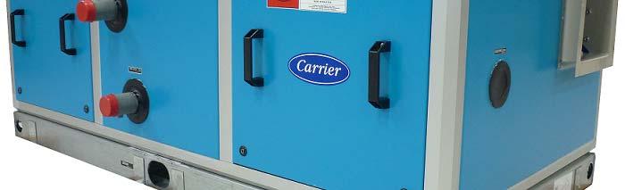


1 39G Galaxy Air Handling Unit MAXIMIZING PERFORMANCE, ENERGY SAVINGS & COMFORT
2 Contents Page Features 3-5 Basic Construction 6 Quick Selection 7 Dimension 8-9 Fan Discharge Outlet Dimension 10 Horizontal Fan Arrangements 11 Mixing Box Section in Module 12 Center to Center Distance for Fan & Motor configuration Base Unit Casing Weight Fan Motor Weight 18 Fan Blower Specifications Filter Type, Dimension and Quantity 21 Coil Weight 22 Guide Specifications
 and Hot Water Coil (1, 2 rows) are also available.")

3 CISB 39G offers Units are design in accordance to: - ARI Standard for coils (ARI 410) Double wall with 1 & 2 40kg/m³ CFC-Free PU insulation (HCFC 141b). Isolates insulation exposure to the air stream. Wide range of coil offering 4, 5, 6, 7, 8 rows and 8, 10, 12, 14 FPI for chilled water. Optimized coil circuiting. DX Coil (4, 6 rows) and Hot Water Coil (1, 2 rows) are also available. All chilled water, DX and Hot Water coils are factory pressure tested at 400 psig as standard. Coil tracks enable easy coil removal for complete cleaning and assurance of a dry unit interior. Powder painted sloped galvanized steel drain pan with bottom drainage. Forward curved, Backward curved and Airfoil fan. - Forward curved sizes 160 to 1000mm diameter - Backward curved / Airfoil blade sizes 225 to 1000mm diameter Low leak construction with hex socket compression, type latch and nitrile gasket on mating panel parameter. Factory installed unit base of 100mm height, constructed of 14 gauge galvanized steel. 50mm Non-Thermal Bridge (NTB) features Composite Corner Piece (Trileg) ABS material. Non-Thermal Bridge (NTB) Aluminium Frame Extrusion. Non-Thermal Bridge (NTB) sandwiched panels and access doors. Non-Thermal Bid Bridge (NTB) quality panel to frame fitting. No condensation problems in humid environment at low internal temperatures. Rigid construction with aluminium frame work and machine-injected rigid polyurethane foam panels. Spring mounted fans for low vibration transmission. 3
 Only requires the use of hexagon wrench to")


.")
 Coils are")


 or power strut type (for fan size")
4 CISB 39G Standard offerings Compression Latch (Hex Socket) Only requires the use of hexagon wrench to open / close the access door Chilled Water Coil with Steel Header Coils are of aluminium/copper plate fins with belled collars and bonded to 12.7mm OD copper tubes by mechanically expansion. The coils have galvanized steel casing and steel headers with male threaded d connections. Sloping Drain Pan and Drain Outlet New drain pan assembly for better drainage, bottom access drain and sloping for rapid water flow and better Internal Air Quality (IAQ). Ready to couple with male connection. Direct Expansion Coil (DX coil) Coils are aluminium/copper with belled collars and bonded 12.7mm OD copper tubes by mechanically expansion. Coil are provided with brass distributors with sweat type connections. Spring Isolator As standard from the factory, the fan and motor assembly are mounted on a common base with color-coded internally mounted spring isolators, which saves site installation cost. Assembly Fan Housing Motor and Base FMB are made of painted heavy gauge mild steel (for fan size 450 and above) or power strut type (for fan size 160 to 400) to ensure proper and easy installation fan housing and motor. 4


 Frame")


5 CISB 39G Standard offerings Bearing Arm Self aligning double row ball bearings mounted within a cost iron housing supported on tubular bearing arm assembly. Taper Lock Pulley Ability to change diameter of pulley according to fan shaft. Pulleys with taper lock bush allows for convenient dismantling and maintenance of drive package, besides offering flexibility in interchanging for different shaft sizes. Fan Discharge Collar Flanged discharge collar to provide easy ducting connection. Handle Grab Large and Non-Conductive handles for easy panel removal. Accessory High Velocity Filter (HVF) Frame For free air return application, factory supplied 75mm HVF track is an option instead of one module casing resulting in shorter overall unit length. Dampers Mixing boxes are equipped with opposed blades interconnected outside with return air dampers. 5


 39G 50mm")
")


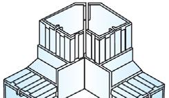
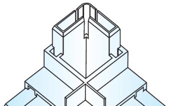
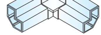
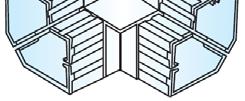
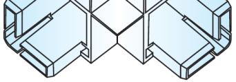
6 Basic Construction 39G 25mm Frame Construction 39G 50mm Frame Construction 39G 50mm NTB Frame Construction 39G 25mm Panel (Double Skin) 39G 50mm Panel (Double Skin) 39G 50mm NTB Panel (Sandwich) 39G 25mm Frame Panel Construction 39G 50mm Frame Panel Construction 39G 50mm NTB Frame Panel Construction 39G 25mm 39G 50mm 39G 50mm NTB Trileg Construction Trileg Construction Trileg Construction 6
 4.5m/s maximum velocity for heating coil only. 2.")
7 Quick Selection Carrier offers you three easy quick selection steps for 39G: 1.) Determine the unit size based on air flow or coil face area. a.) 1.5m/s minimum velocity (cooling or heating). b.) 2.5m/s maximum velocity for cooling coil without drift eliminator. c.) 4.5m/s maximum velocity for heating coil only. 2.) Use roughing-in dimensions (Pg 8) to find approximate size of base unit and it's accessory sections. 3.) Compute weights of base casing unit (Pg 15-17). 4.) To compute total of unit weight and respective fan, coil and motor drive package weight (if applicable). Unit Size Selection 39G Coil Face Area Air Volume (l/s) x 1000 Unit Size (m²) 1.5 m/s 2.5 m/s 4.5 m/s Note: For application where face velocity exceed 2.6m/s (for cooling only), drift eliminators is recommended to avoid moisture carry over under normal operating condition. Computer Selection We have made available a computer program to finalize your selections. Please contact your Carrier representative for a computer selection based on your "Quick Selection" plus the design parameters of your application. 7
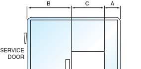
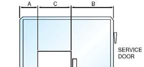
8 Filter Section Bag Filter/ LVF HVF Filter HEPA A Filter Cooling coil / Dual coil (Horizontal) Coil Section Dimension ns Mixing Box Section Economized Mixing Box Double Mixing Box Mixing Box DBL MXB ECN MXB MXB ternal Size 50mm Length h Length Length Width Height th m) Internal Size Ex 25mm eight Width Height Widt mm) (mm He (m G Unit Sizes Fan Size ow. separate packaging. oil section for model 0914 and belo nd coil section will be delivered in s Hot water coil (Horizontal) il unit shipping option: unit, factory pre-join the fan and co 9G1015 and above, fan section an Note: Vertical Fan + Co For vertical u For model 39 Heater Section Horizontal Fan Sec ction Vertical Diffuser Section BF/LVF HVF HE EPA CW HW HTR FCF OR BCF FCF OR BCF FCF OR BCF DIF Length Length Len (m gth m) Length Internal Size Section Length Length Length Leng (mm th m) Height Length S Discharge ection with Damper Plenum Access DISC ACS Length Length
9 Unit Dimension Calculations External AHU Length External AHU Length = (Section Length + K)mm where, K = 50mm (for 25mm casing thickness) or 100mm (for 50mm casing thickness) If the AHU module length is more than 2000mm, section will be split into several casing for shipping purposes. For example, A.) 39G1522, MXB-BF-CCS-FS, Fan Size 500, Horizontal AHU with 50mm casing thickness Module length is mm, equals to 3100mm. Unit will be split into two section: 1.) MXB-BF-CCS: = K(100) = 2100mm 2.) FS: 1100 = K(100) = 1200mm Total AHU Length= 3300mm B.) 39G1522, MXB-BF-CCS-FS, Fan Size 500, Vertical AHU with 50mm casing thickness Module length is mm, equals to 2600mm. Unit will be split into two section: 1.) MXB-BF: = K(100) = 1500mm 2.) FS: 1100 = K(100) = 1200mm Total AHU Length= 2700mm Note: The fan is on top of the coil section, just apply the fan section length for calculation. External AHU Width External AHU Width = (Module Width + K)mm where, K = 50mm (25mm casing thickness) or 100mm (50mm casing thickness) For example: A.) 39G1522, MXB-BF-CCS-FS, Fan Size 500, Horizontal AHU with 50mm casing thickness AHU width = 2200mm + K (100mm) = 2300mm External AHU Height A.) Horizontal AHU = (Module height + K + 100)mm where, K = 50mm (for 25mm casing thickness) or 100mm (for 50mm casing thickness) For example 39G1500, MXB-BF-CCS-FS, Fan Size 500, Horizontal with 50mm casing thickness AHU Height = ( )mm = 1700mm B.) Vertical AHU = (Section Vertical Height + Fan Section Vertical Height + 2K + 100)mm where, K = 50mm (for 25mm casing thickness) or 100mm (for 50mm casing thickness) For example: 39G1522, MXB-BF-CCS-FS, Fan Size 500, Vertical AHU with 50mm casing thickness AHU Height = ( )mm = 3000mm 9
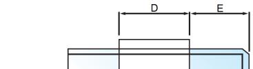
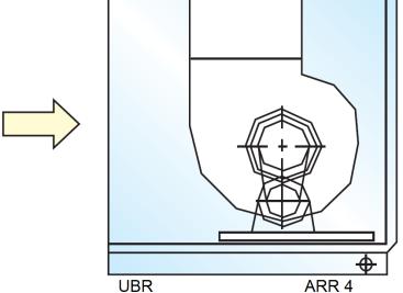
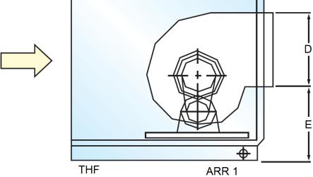
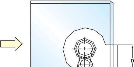
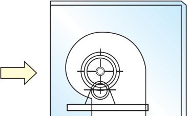
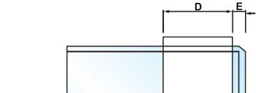
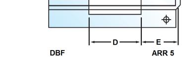
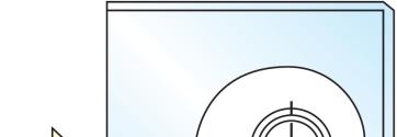
10 Fan Disch harge Outlet t Dimension n B C=D A E UBR 0mm 25mm 50mm BHF UBF mm 50mm 25mm THF 25mm 50mm 25m mm 50mm Max HP 25mm 50mm Fan Size 39G Unit Size DBF DB 25mm 50mm 25mm Refer to page 11. BR UBF (Vert) 50mm 25mm 50mm UBR (Vert) 25mm 50mm
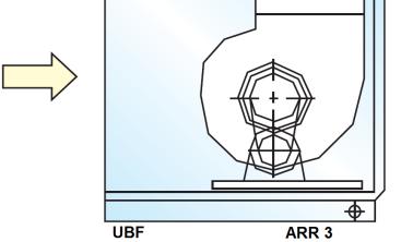
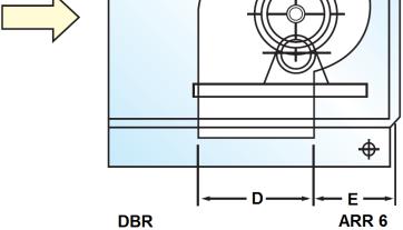
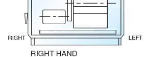
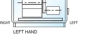
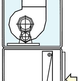
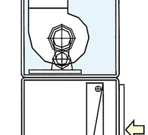
11 Horizontal Fan Arrangements Side Elevation Front Elevation 11
12 Mixing Box Section in Module 39G AHU Size MXB OPPOSED BLADE DAMPER (H x W in mm) DAMPER OPENING SIZE (H x W in mm) TOP REAR SIDE BOTTOM TOP REAR SIDE BOTTOM x x x x x x x x x x x x x x x x x x x x x x x x x x x x x x x x x x x x x x x x x x x x x x x x x x x x x x x x x x x x x x x x x x x x x x x x x x x x x x x x x x x x x x x x x x x x x x x x x x x x x x x x x x x x x x x x x x x x x x x x x x x x x x x x x x x x x x x x x x x x x x x x x x x x x x x x x x x x x x x x x x x x x x x x x x x x x x x x x x x x x x x x
13 Center to Center Dist tance for Fa an and Moto or Configur ration THF/THR CTCD (in mm) ~ 5.5 hp 7.5 ~ 10 hp 15 ~ 20 hp 25 ~ 30 hp 40 hp 50 ~ 60hp 75 hp 100 hp ~ 60hp 75 hp 100 hp 1 hp 1.5 ~ 2hp 3 ~ 4 hp G Fan BHF/BHR CTC CD (in mm) Unit Size Size 1 hp 1.5 ~ 2hp 3 ~ 4 hp 5 ~ 5.5 hp 7.5 ~ 10 hp 15 ~ 20 hp 25 ~ 30 hp 40 hp
14 Center to Center Dist tance for Fa an and Moto or Configur ration in mm) DBF/DBR CTCD (i hp 1.5 ~ 2hp 3 ~ 4 hp 5 ~ 5.5 hp 7.5 ~ 10 hp 15 ~ 20 hp 25 ~ 30 hp 40 hp 50 ~ 60 0hp 75 hp 100 hp ~ 60hp 75 hp 100 hp UBF/UBR CTC CD (in mm) 5 ~ 5.5 hp 7.5 ~ 10 hp 15 ~ 20 hp 25 ~ 30 hp 40 hp hp 1.5 ~ 2hp 3 ~ 4 hp Fan Size G Unit Size
15 Base Uni it Coil Weig ht (25mm Section Weig ght) Mixing Box Mixing Box Section Do Mixi ouble ng Box Economized Mixing Box Bag Filter Section g Filter / LVF HVF Filter HEP PA Filter Cooling/Dual (Horizontal) Coil Section Hot (Hor Heater Section t Water rizontal) Hori Fan Section Diff Sec izontal Vertical user ction Discharge Section with Damper Plen num Acce ess MXB DBL MXB ECN MXB BF / LVF HVF HEPA CW HW HTR FCF or BCF FCF or BCF D IF DISC AC CS 39G AHU Size Fan Size Note: Estimat ted weight in kg
16 Base Uni it Coil Weig Mixi Mixing Box MXB 39G AHU Size Fan Size Note: Est timated weight in kg. ht (50mm Section Weig ght) ing Box Section Double Mixing Box Economized Mixing Box Filter Section Bag Filter / LVF HVF Filter HEPA Filter Coil Se Cooling/Dual (Horizontal) ection Heater Hot Water Section (Horizontal) DBL MXB ECN MXB BF / LVF HVF HEPA CW HW HTR Fan Section Horizontal Vertical FCF or BCF FCF or BCF Diffuser Section Discharge Section with Damper DIF DISC Plenum Access ACS
17 Base Uni it Coil Weig ht (50mm NTB Section Weight) Mixing Box Mixin ng Box Section Double Mixing Box Economized Mixing Box Filter Section Bag Filter / LVF HVF Filter HEPA Filter Coil Se Cooling/Dual (Horizontal) ection Heater Hot Water Section (Horizontal) MXB DBL MXB ECN MXB BF / LVF HVF HEPA CW HW HTR 39G AHU Size Fan Size Note: Estim mated weight in kg Fan Section Horizontal Vertical FCF or BCF FCF or BCF Diffuser Section Discharge Section with Damper DIF DISC Plenum Access ACS
18 Fan Motor Weight Table below shows the approximate fan motor weight. Motor HP Motor kw Motor Shaft Diameter Approx. Weight Frame Number (kg) Notes: D D90S D90L 3/4 22/ D100L 5 / / D112M D132S D132M D160M D160L D180M D180L D200L D225SC D225MC D2250SA Motor weights based on 4-pole, 415/3Ø/50Hz induction type TEFC foot mounted motor. Motor is suitable for direct on-line / reduced voltage starting mechanism. Standard motor shall be per IEC standard IP55 enclosure with Class F insulation and B temperature rise complying with BS2757. Maximum ambient temperature 40 C. For derivation of motor kw from fan BkW use. Motor kw = Fan BkW x A, where A = 1.20 if BkW < 10kW A = 1.15 if BkW > 10kW Please refer to your nearest Carrier representatives for special motor voltages or application. 18
19 Height, H Length, L Forward Curv ved Maximum BkW Fan Model 3 ADH 50 3 ADH 56 4 ADH 63 4 ADH 71 4 ADH ADH ADH FDA CM 7.5 FDA CM 11 FDA CM 11 FDA CM 15 FDA CM 15 FDA CM 18.5 FDA CM 4 FDA CM 4 FDA CM 7.5 FDA CM 11 FDA CM 11 FDA CM 15 FDA CM 15 FDA TM 15 FDA TM 15 FDA TM 18.5 FDA TM 18.5 FDA TM 22 FDA TM 22 FDA TM 30 FDA TM 37 FDA TM 18.5 FDA TM 22 FDA TM 22 FDA TM 30 FDA TM ation Fan Blow wer Specific Width, W Shaft Dia Fan Max RPM Weight (Kg) 20 h h h h h h h h h h h h h h h h h h h h h h h h h h h h h h h h h h h h h h h Weight Fan Model ADH 160 R ADH 180 R ADH 200 R ADH 225 R ADH 250 R ADH 280 R ADH 315 R ADH 355 R ADH 400 R ADH 450 R ADH 500 R ADH 560 R ADH 630 R ADH 710 R ADH 200 K ADH 225 K ADH 250 K ADH 280 K ADH 315 K ADH 355 K ADH 400 K ADH 450 K ADH 500 K ADH 560 K ADH 630 K ADH 710 K ADH 800 K ADH 900 K ADH 1000 K ADH 315 K1 ADH 355 K1 ADH 400 K1 ADH 450 K1 ADH 500 K1 ADH 560 K1 ADH 630 K1 ADH 710 K1 ADH 800 K1 ADH 900 K1 (Kg) 0 K K K K K K K M M M M M M M M M M M M M M M M M M M M M M M M M M Fan Max R PM Shaft Dia Width h, W (mm m) h h h h h h h g g g g g g g g g g g g g g g g g g g g g g g g g g6 136 Height, H Length (mm m) h, L Maximum BkW
20 Height, H Length, L Backward Curv ved M aximum BkW Fan Mod del 2.2 BDB CM 20 3 BDB CM 22 4 BDB CM 25 4 BDB CM BDB CM BDB CM BDB CM BDB CM BDB CM BDB CM BDB CM BDB CM 7 15 BDB TM 31 3 BDB TM 35 4 BDB TM BDB TM BDB TM BDB TM BDB TM BDB TM BDB TM BDB TM BDB TM BDB XM BDB XM BDB XM AIRFOIL 11 RZR RZR RZR RZR RZR RZR RZR RZR RZR RZR RZR RZR RZR Weight ation Fan Blow wer Specific Width, W Fan Ma ax Shaft Dia RPM Weight Fan Mo odel (Kg) 20 h h h h h h h h h h h h h h h h h h h h h h h h h h h h R R R R R R R R R R R R R K K K K K K K K K K K K K K K h h h h h h h h h h h h h h h h h K K K K K K K K K K K K K K K K K (Kg) RDH 180 RDH 200 RDH 225 RDH 250 RDH 280 RDH 315 RDH 355 RDH 400 RDH 450 RDH 500 RDH 560 RDH 630 RDH 710 RDH 200 RDH 225 RDH 250 RDH 280 RDH 315 RDH 355 RDH 400 RDH 450 RDH 500 RDH 560 RDH 630 RDH 710 RDH 800 RDH G G Fan Max Shaft Dia RPM Width, W 20g g g g g g g g g g g g g g g g g g g g g g g g g g k k k k k k k k k k k k k Height, H Length, L Ma ximum BkW RDH 100 RDH 315 RDH 355 RDH 400 RDH 450 RDH 500 RDH 560 RDH 630 RDH 710 RDH 800 RDH 900 RDH 500 RDH 560 RDH 630 RDH 710 RDH 800 RDH 900 RDH 100
21 Filter Type, Dimension and Quantity TYPE HEPA filter EU13 P/brd HEPA filter EU13 Alum HEPA filter EU14 P/brd HEPA filter EU14 Alum 1" Bag Filter EU5 1" Bag Filter EU6 1" Bag Filter EU7 er 1" Bag Filt EU8 Filter 9 1" Bag EU 2" HVF filter G03 2" HVF filter G04 DIMENSION PART NO. 39G UNIT SIZE H289 X W595 3GA H391 X W495 3GA H391 X W595 3GA H595 X W595 3GA H289 X W595 3GA H391 X W495 3GA H391 X W595 3GA H595 X W595 3GA H289 X W595 3GA H391 X W495 3GA H391 X W595 3GA H595 X W595 3GA H289 X W595 3GA H391 X W495 3GA H391 X W595 3GA H595 X W595 3GA H289 X W595 39GA H391 X W495 39GA H391 X W595 39GA H595 X W595 39GA H595 X W289 39GA H595 X W391 39GA H595 X W595 39GA H289 X W595 39GA H391 X W495 39GA H391 X W595 39GA H595 X W595 39GA H595 X W289 39GA H595 X W391 39GA H595 X W595 39GA H289 X W595 39GA H391 X W495 39GA H391 X W595 39GA H595 X W595 39GA H595 X W289 39GA H595 X W391 39GA H595 X W595 39GA H289 X W595 39GA H391 X W495 39GA H391 X W595 39GA H595 X W595 39GA H595 X W289 39GA H595 X W391 39GA H595 X W595 39GA H289 X W595 39GA H391 X W495 39GA H391 X W595 39GA H595 X W595 39GA H595 X W289 39GA H595 X W391 39GA H595 X W595 39GA H289 X W595 39GA H391 X W495 39GA H391 X W595 39GA H595 X W595 39GA H289 X W595 39GA H391 X W495 39GA H391 X W595 39GA H595 X W595 39GA
22 Coil Weig ght Chilled Estimated Dry C 2 4 Type of Coil Hot Water No of Row Fin ns/inch 39G Face Area Unit Size (m m³) Water ion. f rows x 7.0kg/sq.m. ove data (kg) x 3.3. aluminium plated fin constructi use Face area (sq.m) x no. of te fin construction, use the abo 2.7mm OD copper tubes with a weight of water content (kg), u coil weight (kg) for copper plat Note: 1. All coils are of To estimate the w 3. To estimate dry c oil Weight (kg) Direct Expan nsion
23 Guide Specifications GENERAL 1. Furnish and install central air handling units of the type, size and capacity shown on the equipment schedule. 2. Equipment schedules are based on Carrier 39G C-series. The design of the air handling unit is based on the use of modular panels and extruded aluminum perimeter frames with composite corner piece. 3. Units shall be horizontal/vertical draw-through type or horizontal blow-through type as shown on the certified drawings. In general, the unit shall consists of: Mixing box section Filter section Coil section Access or Plenum section Fan section CASING 1. Unit shall be constructed of a complete frame with easily removable panels. Removal of any panel shall not affect the structural integrity of the unit. 2. All 39G unit sections shall be supplied with 14-gage G90 galvanized (100mm height) steel structural unit base. Holes are provided for rigging purposes and are positioned to suit optimum hoisting stability. 3. Casing panels shall be solid double wall of 50mm (or 25mm) nominal construction with injection foam insulation in between. The outer panel shall be painted 0.5mm thick galvanized steel (sky blue color RAL 5012) and inner panel shall be unpainted 0.5mm thick galvanized steel. The coating shall meet or exceed ASTM B117 Standard for 500-hour salt spray test. 4. The casing panels shall be insulated with injected insitu CFC-Free Polyurethane insulation foam with thermal conductivity of 0.020W/mK and a density of 40kg/m 3 in between. The insulation shall be sandwiched and encapsulated between the inner and outer panel. Exposed insulation is not acceptable. 5. Casing panels shall have no exterior exposed raw edges that could lead to rust formation. All casing corners shall be radiused or chamfered. 6. All panels shall seal against a full casing perimeter with nitrile gasket to ensure a tight seal. 7. Mixing boxes shall be solid double wall, insulated and complete with necessary air dampers for return and fresh air mixing. Accessibility options shall be hinged access door on hand side, hinged access doors on both sides, or removable access doors. a. Viewports shall be available as a factory-installed option on the door of this section. b. Marine lights shall be available as a factory-installed option. 8. Filter section shall be solid double wall, insulated and complete with necessary tracks for filters installation. Accessibility options shall be hinged access door on hand side, hinged access doors on both sides, or removable access doors. a. Pressure gages or switches shall be available as a factory-installed option b. Filter sections shall be designed and constructed to house one of the following filter types: Face/side loading 25mm or 50mm pre-filters Side loading 50mm angle filters Face loading 529mm bag filters with 50mm pre-filters Side loading 529mm bag filters Face loading HEPA filters 9. Coil sections shall have solid double wall and insulated casing. Accessibility options shall be hinged access door or removable access doors (applicable for vertical type). 10. Access and plenum sections shall have solid double wall and insulated casing. Accessibility options shall be hinged access door on hand side, hinged access doors on both sides or removable access doors. a. Viewports shall be available as a factory-installed option on the door of this section. b. Marine lights shall be available as a factory-installed option. 23
24 Guide Specifications CASING (cont ) 11. Fan section shall have solid double wall and insulated casing. Accessibility options shall be hinged access door on hand side, hinged access doors on both sides or removable access doors. a. Viewports shall be available as a factory-installed option on the door(s) of this section. b. IP44 marine lights shall be available as a factory-installed option. c. Blow-thru sections shall have a diffuser plate as an integral part of the fan section if used immediately downstream of the fan section. FANS A. General 1. Forward-curved fans shall have one double width double inlet (DWDI) fan wheel and scroll. They shall be constructed of galvanized steel. They shall be designed for continuous operation at the maximum rated fan speed and motor horsepower. Completed fan assembly shall be statically and dynamically balanced in accordance to ISO Backward inclined fans shall have one double width double inlet (DWDI) fan wheel and scroll. The fan assembly shall be cleaned, primed and painted with alchidic-melamminic paint. They shall be designed for continuous operation at the maximum rated fan speed and motor horse-power. Completed fan assembly shall be statically and dynamically balanced in accordance to ISO Airfoil fan sections shall have one double width double (DWDI) airfoil fan wheel and scroll. The fan assembly shall be cleaned, primed and painted with epoxy paint. Completed fan assembly shall be statically and dynamically balanced in accordance to ISO Fan wheels shall be keyed to the shaft and shall be designed for continuous operation at maximum rated fan speed and motor horsepower. Fan wheels and shafts shall be selected with a maximum operating speed 25% below the first critical. 5. Fan shafts shall be solid carbon steel, turned, ground, polished and coated with protective paint. Hollow shafts are not acceptable. B. Performance Ratings Air performance ratings of the fans shall be rated and certified in accordance with AMCA C. Sound Ratings Manufacturer shall publish first through eighth octave sound power for fan inlet and fan discharge. D. Mounting Fan scroll, wheel, shaft, bearings, drives, and motor shall be mounted on a common base assembly. The base assembly shall be isolated from the outer casing with factory-installed 2 spring isolators and flexible canvas connection. FAN MOTOR 1. The motor size, type, speed and its electrical characteristics shall be as per the equipment schedule. 2. Fan motors shall be mounted within the fan section casing on slide rails to aid in belt tightening. 3. Fan motors shall be IP55, high efficiency (EFF2), totally enclosed fan cooled (TEFC) with class F insulation. Optional premium efficiency (EFF1) motors shall be available, if specified. 4. The motor shall be suitable for operation at ambient temperature of 40 o C (max) with ±10% voltage utilization range and a 1.15 minimum service factor. 24
25 Guide Specifications DRIVES 1. The di drive assembly shall consist of V-belts and aset of fan and motor pulley. 2. The V-belts shall be SPZ, SPA, SPB or SPC grades, oil and heat resistance and having anti static characteristic which prevent electrical discharge. 3. The motor and fan pulley dimension shall conform to ISO 4183 and shall be using taper-lock bush with set screws for easy and quick assemble and disassemble process. The pulley shall be phosphated and coated with a layer of rust prohibitive paint for protection against corrosion. 4. Drive shall be designed for a minimum 1.5 service factor as standard with a 2.0 service factor options. Drives shall be fixed-pitch with variable pitch as an option. All drives shall be factory mounted, with sheaves aligned. COILS A. All cooling, heating and refrigerant (DX) coils shall be provided to meet the scheduled performance. All coil performances shall be rated in accordance with ARI Standard 410 and shall be tested at 400 psig air pressure while submerged under water. B. General Fabrication 1. All water and refrigerant coils shall have minimum 12.7mm (1/2-in.) OD copper tubes mechanically expanded into fins to ensure high thermal performance. 2. Aluminum fin type shall be with belled collars. Optional copper fins or fins with protective coatings shall be supplied, if specified. 3. Aluminum-finned coils shall be supplied with die formed casing and galvanized steel tube sheet. Optional stainless steel or aluminum tube sheet shall be available if specified. Copper-finned coils shall be supplied with stainless steel casing and tube sheets. 4. Moisture eliminator shall be provided if specified on the equipment schedule. The moisture eliminator material shall be mesh aluminum type or PVC type as specified. C. Cooling and Heating Coils 1. Headers shall be constructed of steel with MPT connections. Headers shall have drain and vent connections accessible from the exterior of the unit. Optional non-ferrous headers with sweat connection shall be supplied if specified. 2. Coils shall be drainable, with non-trapping circuits and without turbulence promoting devices. Coils will be suitable for a design working pressure of 300 psig at 93 o C (cooling coils) or 175 psig at 205 o C (heating coils). 3. Coil shall be designed for counter flow arrangements. D. Refrigerant (DX) Coils 1. Headers shall be constructed of copper with brazed joints. 2. Standard circuiting selections include optional single distributor arrangement (for 39G G0813) and dual distributor arrangement for most sizes for face split or intertwined row split as specified. Brass nozzles and distributors are factory supplied to ensure uniform flow. Expansion valves shall be provided if specified. 3. Coil shall be designed for counter flow arrangements. 25
26 Guide Specifications E. Drain Pans 1. Drain pans shall be single wall,1.0mm thick galvanized (and powder painted) or SS304 stainless steel construction as specified. The drain pan depth shall be 40mm with 500mm width and insulated with 3mm PE closed cell insulation underneath to prevent condensation. 2. The pan shall be sloped toward the drain fitting to ensure positive condensate drainage and shall extend downstream of the coil to provide sufficient amount of space to contain moisture carry-over. Drain pan shall allow no standing water. 3. Drain pan shall have a recessed bottom drain design with integral FPT elbow (43mm OD) for side discharge and trapping. One drain outlet shall be supplied for each cooling coil section unless otherwise indicated. 4. Where 2 or more coils are stacked in a coil bank, intermediate drain pans shall be provided and the condensate shall be piped to the bottom drain pan. The bottom coil shall not serve as a drain path for the upper coil. 5. The coil shall not sit in the drain pan and shall be removable via a coil track. ELECTRIC HEATERS 1. Electric heater capacity and steps shall be as indicated on the equipment schedule. 2. The electric heater element shall be constructed from 80/20 nickel chrome resistance wire which is connected to terminal pins and centered in SS304 stainless steel sheath tubes by compressed magnesium oxides. 3. The manufacturer shall furnish a control box containing contactor, thermostat and circuit breaker. Heater control box shall be mounted on the designated hand side of the unit. FILTER SECTIONS 1. Provide the type and efficiency of the filters as per the equipment schedule. 2. High velocity filter sections shall accept 25mm or 50mm (G3 or G4) washable or throw-away filters. 3. Angle filter sections shall accept 50mm (G3) washable filters of standard flat filter sizes, arranged in a horizontal V formation. 4. Bag filter sections shall be capable of accepting (F5 - F9) bag filters with length up to 529mm with 22mm header. 5. Blow-thru HEPA filter sections shall contain a face loading filter frame and be capable of accepting standard size 300mm deep HEPA filters (H13-H14). 6. Optional Magnehelic filter gages complete with necessary tubing to measure the pressure drop across the filters shall be provided if specified. MXB DAMPERS 1. Provide factory installed opposed acting dampers as per the approved drawings. 2. Damper frame shall be made of extruded and anodized aluminum. Damper blades shall also be extruded and anodized aluminum airfoil shape to withstand high velocity and static pressure. Dampers shall be provided with flexible synthetic blade edge seals for low leakage application. 3. Damper shall be sectionalized to limit blade length to be less than 1800mm in order to prevent excessive blade warping. Outdoor air and return air damper size shall be of the same area for equal air mixing. 26


27 Carrier International Sdn Bhd, Malaysia Manufacturer reserves the right to discontinue, or change at anytime, specifications or designs without notice and without incurring obligations. 39GC-C12-1PD
AIR HANDLING UNIT 39G GALAXY
 AIR HANDLING UNIT 39G GALAXY 1 CISB 39G offers... Units are designed in accordance to - ARI Standard for Coils (ARI 410) - ASHRAE Standard for Drain Pan (ASHRAE 62-89) Double Wall with 1, 2 & 3 40kg/m
Prepared By : Checked By : Approved By : Page 1 out of 6
 Software Name Carrier AHU - Version 1.0, Patch R1.1X UNIT MODEL GENERAL SPECIFICATIONS GENERAL LOCATION / WEIGHT UNIT DIMENSION Configuration : Quick Selection Wizard Unit Orientation : Horizontal Box
SPECIFICATIONS AND DESIGN ARE SUBJECT TO CHANGE WITHOUT PRIOR NOTICE. EDITION 11
 AIR HANDLING UNIT (DOUBLE SKIN) MODEL: DS-CW/DX-AHU-H (Chilled Water or Direct Expansion) CAPACITY: 3.3 to 125 Nominal Tons 39,000 to 1,500,000 BtuH 11.4 to 439.5 KW 1,300 to 50,000 CFM Benefits Horizontal
Complete HVAC Capability
 Air Handling Units Brochure 1110 January 2006 Complete HVAC Capability MEA Horizontal Draw-Thru to Size 65 Vertical Draw-Thru to Size 50 1000 to 60,000 CFM Forward Curved or Airfoil Wheels Inlet Vane Option
AIR HANDLING UNIT. MODEL: PM0809 to PM CFM to CFM
 AIR HANDLING UNIT MODEL: PM0809 to PM2738 700CFM to 41000 CFM POWER METAL TECHNOLOGIES (M) SDN BHD Lot 37830, Jalan Bukit Naga, Kampung Bukit Naga, Section 32, 40460 Shah Alam, Selangor Darul Ehsan. Tel:
ELTAFANTECH Air Handling Unit 700 up to 42,000 CFM
 an ELTA GROUP company ELTAFANTECH 700 up to 42,000 CFM INNOVATIVE Design & Performance INTRODUCTION There are 24 standard sizes of optimally engineered s to handle air volumes from 700 CFM to 42,000CFM.
Submittal DIMENSIONS SIZE FAN SIZE L W H C D E F G J K [406] [508] 25 [635] [406] 16 [406] 16 [406] 39-1/2 [1003] 44-1/2 [1130] 51 [1295] 59 [1499]
![Submittal DIMENSIONS SIZE FAN SIZE L W H C D E F G J K [406] [508] 25 [635] [406] 16 [406] 16 [406] 39-1/2 [1003] 44-1/2 [1130] 51 [1295] 59 [1499]](/thumbs/94/122284584.jpg "Submittal DIMENSIONS SIZE FAN SIZE L W H C D E F G J K [406] [508] 25 [635] [406] 16 [406] 16 [406] 39-1/2 [1003] 44-1/2 [1130] 51 [1295] 59 [1499]") BC--1.0 03-01-1 Belt Drive Blower Coil Unit, Basic Unit Discharge ARGT. 1 4. See page 1 for filter rack details. 5. Base rail is optional on he base unit. See page 13. Base rails must be used with mixing
BC--1.0 03-01-1 Belt Drive Blower Coil Unit, Basic Unit Discharge ARGT. 1 4. See page 1 for filter rack details. 5. Base rail is optional on he base unit. See page 13. Base rails must be used with mixing
MODULAR SINGLE AND DOUBLE WALL BELT DRIVE AIR HANDLER DX OR CHILLED WATER COOLING HOT WATER OR ELECTRIC HEATING
 MODULAR SINGLE AND DOUBLE WALL BELT DRIVE AIR HANDLER DX OR CHILLED WATER COOLING HOT WATER OR ELECTRIC HEATING SIZES FROM 600 TO 9,000 All Technical Specifications are Subject to Change without Notice.
MODULAR SINGLE AND DOUBLE WALL BELT DRIVE AIR HANDLER DX OR CHILLED WATER COOLING HOT WATER OR ELECTRIC HEATING
 MODULAR SINGLE AND DOUBLE WALL BELT DRIVE AIR HANDLER DX OR CHILLED WATER COOLING HOT WATER OR ELECTRIC HEATING MADE IN USA SIZES FROM 600 TO 9,000 All Technical Specifications are Subject to Change without
CS3 Series 50/60Hz. Modular Central Station Air Handling Units Air Volume: 1000 to cfm (1700 to m 3/hr)
") CS3 Series 50/60z Modular Central Station Air andling Units Air Volume: 1000 to 56000 cfm (1700 to 90 m 3/hr) Products that perform...by people who care DUNAM-BUS CS3 Series Introduction For more than
CS3 Series 50/60z Modular Central Station Air andling Units Air Volume: 1000 to 56000 cfm (1700 to 90 m 3/hr) Products that perform...by people who care DUNAM-BUS CS3 Series Introduction For more than
SBH / SBV Sales Guide BLOWER-COILS HORIZONTAL AND VERTICAL
 SO TOUGH, WE GUARANTEE IT. SBH / SBV Sales Guide BLOWER-COILS HORIZONTAL AND VERTICAL SBH SBV www.superiorrex.com SO TOUGH, WE GUARANTEE IT! www.superiorrex.com SBH / SBV Series: CONSTRUCTION FEATURES
ROOF TOP SINGLE AND DOUBLE WALL BELT DRIVE AIR HANDLER DX OR CHILLED WATER COOLING HOT WATER OR ELECTRIC HEATING
 ROOF TOP SINGLE AND DOUBLE WALL BELT DRIVE AIR HANDLER DX OR CHILLED WATER COOLING HOT WATER OR ELECTRIC HEATING MADE IN USA SIZES FROM 600 TO 9,000 All Technical Specifications are Subject to Change without
DUNHAM-BUSH ecs3 Series
 DUNAM-BUS ecs3 Series INTRODUCTION For more than 100 years, Dunham-Bush has focused on innovative product development. Today, we provide a full portfolio of VAC/R products from Coil Units to large centrifugal
MODULAR AIR HANDLING UNITS GAH SERIES
 MODULAR AIR HANDLING UNITS GAH SERIES 15 Models with Air Flows from 2,250 Cu.m/hr upto 77,800 Cu.m/hr Suitable for both Standard and District Cooling Applications GAH-TC-10-13 CONTENTS Design 2 Various
VERTICAL SINGLE AND DOUBLE WALL BELT DRIVE AIR HANDLER DX OR CHILLED WATER COOLING WITH HOT WATER OR ELECTRIC HEAT
 VERTICAL SINGLE AND DOUBLE WALL BELT DRIVE AIR HANDLER DX OR CHILLED WATER COOLING WITH HOT WATER OR ELECTRIC HEAT SIZES FROM 600 TO 4,000 All Technical Specifications are Subject to Change without Notice.
42CET/ 42CED Series Chilled Water Fan Coil Unit Furred-in Ceiling Model 300 to 1400 cfm Electric heater option
 42CET/ 42CED Series Chilled Water Fan Coil Unit Furred-in Ceiling Model 0 to 10 cfm Electric heater option 42DC/ 42DCD Series Chilled Water Fan Coil Unit Furred-in Ceiling Model 0 to 00 cfm Electric heater
MAH. Modular Air Handling Unit
 MA Modular Air andling Unit 500 to 11,000 CFM @ up to 6.00 TSP 2 and 4 double wall construction, perforated or solid lined 18 gauge G0 galvanized steel cabinet 26 standard cabinet sizes available Internally
HORIZONTAL SINGLE AND DOUBLE WALL BELT DRIVE AIR HANDLER DX OR CHILLED WATER COOLING WITH HOT WATER OR ELECTRIC HEAT
 HORIZONTAL SINGLE AND DOUBLE WALL BELT DRIVE AIR HANDLER DX OR CHILLED WATER COOLING WITH HOT WATER OR ELECTRIC HEAT MADE IN USA SIZES FROM 600 TO 9,000 All Technical Specifications are Subject to Change
The World Leading Air-conditioning Company
 The World Leading Air-conditioning Company Table of Contents DESCRIPTIONS Model Number Nomenclature Features & Benefits Physical Dimension Fan Performance Curve (4 Row) - 40LMA024 with AC Motor - 40LMA040
D M S 760 C01 A A 1 1
 CONTENTS Description Features Options Available Selection Method Product Data Cooling Performance Data (85 F Ambient Cooling Performance Data (95 F Ambient) Cooling Performance Data (105 F Ambient)..............................
McQuay MDM Air Handling Unit CMDM
 McQuay MDM Air Handling Unit CMDM - 2004 Contents Page Nomenclature System... 1 Features... 2 Performance Tables... 4 Outlines and Dimensions... 15 Section Weights... 23 Installation... 25 Operation...
WE ARE PLEASED TO PROVIDE THE ENCLOSED SUBMITTAL FOR YOUR REVIEW AND APPROVAL
 PREPARED FOR: DATE: JOB NAME: WE ARE PLEASED TO PROVIDE THE ENCLOSED SUBMITTAL FOR YOUR REVIEW AND APPROVAL EQUIPMENT DETAILS ITEM TAG DESCRIPTION MODEL NUMBER 1 2 3 4 5 6 7 8 9 10 11 12 13 14 15 EQUIPMENT
1 AIR HANDLING UNIT TYPE AIR ACCESS 75
 SUPPLY 1 AIR HANDLING UNIT TYPE AIR ACCESS 75 Location : EXTERNAL Position : SIDE BY SIDE SLIDING PANELS for COMPLETE ACCESSIBILITY MULTI SERVICE BULKHEAD for HYDRAULIC AND ELECTRICAL CONNECTIONS Self-supporting
VAHU Vertical Air Handling Unit
 500 to 5,400 CFM @ up to 6.00" TSP 2" double wall construction, perforated or solid lined 18 gauge G90 galvanized steel cabinet 4 standard cabinet sizes available Internally isolated direct drive plug
42C/D SERIES Ducted Chilled Water Fan Coil Unit With District Cooling Application
 42C/D SERIES Ducted Chilled Water Fan Coil Unit With District Cooling Application MAXIMIZING PERFORMANCE, ENERGY SAVINGS & COMFORT MODEL NUMBER NOMENCLATURE 4 2 C E T 0 0 3 4 7 0 1 2 5 42 series CISB Code
AIR HANDLING UNITS. Customisable modular air handling unit, designed and built to suit your project requirements
 AIR HANDLING UNITS Customisable modular air handling unit, designed and built to suit your project requirements PacAir Modular Air Handling Units by are customisable, designed and built for n, New Zealand
Fan Coil Units POWERED BY KLIMAK ITALY
 Fan Coil Units POWERED BY KLIMAK ITALY Index Chilled Water Fan Coil Unit Decorative Fan Coil... Concealed Ducted Fan Coil Unit (Low ESP)...11 Concealed Ducted Fan Coil Unit (Medium ESP)...1 Concealed
DECORATIVE FAN COIL UNIT DECORATIVE FAN COIL UNIT SPECIFICATIONS
 DECORATIVE FAN COIL SPECIFICATIONS UNIT CABINET Single skin or double skin casing (inner perforated sheet or flat sheet) made of powder coated galvanized steel assembled in aluminum extrusion profiles,
The Premium Quality Fan Coil Units for Horizontal Application Hydronic or Electric Heat
 Producing Quality Heating & Cooling Equipment For Over 50 Years CEA SERIES CEILING EPOSED HORIZONTAL FAN COIL UNITS The Premium Quality Fan Coil Units for Horizontal Application Hydronic or Electric Heat
FS Fan-Coil Units Hi-Rise, Vertical
 FS Fan-Coil Units Hi-Rise, Vertical FSC Concealed Dimensional Data 4-PIPE 2-PIPE TOP VIEWS Page Trims Short (5/8") Here! SIDE VIEW FRONT VIEW Dimensions Unit Size A B Single/Double Supply C D E 03 & 04
Commercial Blower Coil Air Handlers
 Commercial Blower Coil Air Handlers MODEL : BDH(V)B - 048, 065, 080 7400 CMH - 14300 CMH 30 kw - 125 kw BCXB-PRC001-E4 Contents Model Number Description General Specification Standard Features Unit Configuration
CHILLED WATER DUCTED FAN COIL
 SD CHILLED WATER DUCTED AN A Series B Series (Double Skin) General abricated with a rigid galvanized steel casing. The DIDW centrifugal fans have balanced, galvanized steel, and forward curved blades.
Midea Air Handling Unit
 Midea Air Handling Unit Floor mounted 3000CFM ---25000CFM Vertical mounted 3000CFM ---25000CFM Ceiling suspended 1000CFM ---9000CFM Midea reserves the right to improve the product and technology without
Product Data. Features/Benefits. 42BH System Fan Coil. 800 to 4000 Cfm
 Product Data 42BH System Fan Coil 800 to 4000 Cfm Satisfy All Your Design Requirements with Carrier s Versatile 42BH Fan Coil Unit A selection of 6 sizes covers capacities from 800 to 4000 cfm Choice of
RBV Sales Guide FAN COIL UNITS FLOOR-MOUNTED, VERTICAL
 RBV Sales Guide FAN COIL UNITS FLOOR-MOUNTED, VERTICAL RBVS RBVR RBVC www.superiorrex.com RBV Series: LOW POWER CONSUMPTION, ACCESSIBLE AND FLEXIBLE Owners Owners can choose between a standard or elevated
BHH Product Specifications
 BHH Product Specifications HORIZONTAL BELT DRIVE DIRECT EXPANSION BLOWER COIL UNITS ALL S 3, 4, and 5 Ton 208/230 3 60 and 460 3 60 supply voltage Units are ETL listed to U.S. and Canadian safety standards
Product Data. Features/Benefits. 39NX Central Station Air-Handling Units. Nominal 2,000 to 55,000 Cfm
 Product Data 39NX Central Station Air-Handling Units Nominal 2,000 to 55,000 Cfm Features/Benefits Sloped, double-wall coil condensate drain pan complies with ASHRAE Standard 62 Double-wall casings solid,
 Issue 4 (Record Only) Job #: Innovent Submittal Date: October 30, 2012 Project: Location: Columbus, OH Innovent Job #: Submittal Issue: 4 (Record Only) Engineer: Contractor: Tag Innovent Model # AHU-BG-01
McQuay. Central Station Air Handler. LHD, LML, LSL, LWL, LYF, MMM, MSL, MWL Vintage D. LML, LSB, MMM, MSB Vintage E
 Replacement Parts List No. 046902100 Revision D 01/2015 McQuay Central Station Air Handler LHD, LML, LSL, LWL, LYF, MMM, MSL, MWL 137-172 Vintage D LML, LSB, MMM, MSB 137-172 Vintage E Last Manufactured:
Nomenclature. Contents. Air Handling Unit SR AH 250 LP HS
 SARAN Mf g. Group 1 Contents Features...... 2-4 Selection Procedures... 5-7 Capacity Ratings (Chilled Water, D.X Coil, Hot Water, Steam Ratings)... 8-15 Correction Factor Tables... 16-18 Dimensions (Horizontal
PCXDMT1601. VRV AHU System STANDARD SERIES AHUR-CAVJ/DAVJ/DABVJ OUTDOOR AIR SERIES AHUR-CALJ/DALJ/DABLJ. Heat Pump 50/60 Hz R-410A
 PCXDMT1601 VRV AHU System STANDARD SERIES AHUR-CAVJ/DAVJ/DABVJ OUTDOOR AIR SERIES AHUR-CALJ/DALJ/DABLJ Heat Pump 50/60 Hz R-10A Airport Lobby Hospital Factory Shopping Mall Sports Hall Showroom Warehouse
RAV Sales Guide FAN COIL UNITS HI-RISE, VERTICAL
 RAV Sales Guide FAN COIL UNITS HI-RISE, VERTICAL RAVS RARM RARS RAVE RAVM RAVL RARP RISER www.superiorrex.com RAV Series: VERTICAL HI-RISE CONCEALED SO TOUGH, WE GUARANTEE IT! www.superiorrex.com Model
TVS/R FAN COIL UNITS HI-RISE, VERTICAL
 TVS/R FAN COIL UNITS HI-RISE, VERTICAL TVRM TVRP Riser TVRS TVSE TVSM TVSR TVSS Redefine your comfort zone. www.titus-hvac.com Redefine your comfort zone www.titus-hvac.com Model TVS/R: CONCEALED, HI-RISE
Product Data. 39T Central Station Air-Handling Units. Features/Benefits. Nominal 3,500 to 46,000 Cfm
 Product Data 39T Central Station Air-Handling Units Nominal 3,500 to 46,000 Cfm Features/Benefits Flanged and gasketed modular components units are available as a single assembly up to 40 ft long, or shipped
"SPOAU" DEDICATED 100% OUTSIDE AIR UNITS Self Contained Single Package or Split System Units
 "SPOAU" DEDICATED 100% OUTSIDE AIR UNITS Self Contained Single Package or Split System Units Spinnaker Industries Inc. Model Series SPOAU 100% Outdoor Air Systems shall be factory assembled, wired and
Horizontal and Vertical BELT DRIVE AIR HANDLING UNITS
 Horizontal and Vertical BELT DRIVE AIR HANDLING UNITS TABLE OF CONTENTS H & V Features and Benefits...4 Coil and Filter Data, Static Pressure Data...7 Electric Resistance Heat Section...8 Coil Information
SARAVEL MINI AIR-HANDLING UNIT
 CAT-MAHU-2003(1) SARAVEL MINI AIR-HANDLING UNIT 800 TO 5500 CFM ( 1400 TO 9300 m³/hr ) 1 TABLE OF CONTENTS Introduction... 3 Specifications 4 Examples.... 5 Coil Circuiting & Physical Data..... 7 Rating
GENERAL ELECTRIC CONCEALED CHILLED WATER FAN COIL UNITS
 GENERAL ELECTRIC CONCEALED CHILLED WATER FAN COIL UNITS ACWL Series ACWL0 thru ACWL4 00 CFM thru 400 CFM GE_ACWL_series.indd 3// : PM CONTENTS Model decoding 3 Unit features 3 Standard specifications 3-4
technical sales guide - 60Hz Ducted Split Units HIGH AMBIENT OPERATION 52 UPTO
 technical sales guide - 60Hz Taurus R Ducted Split Units UPTO HIGH AMBIENT OPERATION 52 O C Page CONTENTS Nomenclature.. 2 Description. 3 Features.. 3 Product Data. 4 Condensing Unit Cooling Performance
Climas y Proyectos Leyco, S.A. de C.V.
 GENERAL DESCRIPTION : FURNISH AND INSTALL MULTI COMPONENT ROOF MOUNTED LEYCO, MODEL CAH CUSTOM AIR HANDLER MADE SELF-CONTAINED, WEATHER RESISTANT, AIR HANDLING UNITS PER MODEL NUMBER, AND PERFORMANCE DATA
AHTW Compact. Heat Recovery Air Handling Unit. BIM & REVIT Engineering Solutions. Acoustic Testing Laboratory College of Science & Technology
 HANDLERS LTD AHTW Compact Heat Recovery Air Handling Unit 1262 Acoustic Testing Laboratory College of Science & Technology BIM & REVIT Engineering Solutions The Company Air Handlers has been trading since
PCXAU1601. VRV AHU System STANDARD SERIES AHUR-CAVJ/DAVJ/DABVJ OUTDOOR AIR SERIES AHUR-CALJ/DALJ/DABLJ. Heat Pump 50/60 Hz R-410A
 PCXAU161 VRV AHU System STANDARD SERIES AHUR-CAVJ/DAVJ/DABVJ OUTDOOR AIR SERIES AHUR-CALJ/DALJ/DABLJ Heat Pump 5/6 Hz R-1A An industry first, the VRV air handling unit has been designed and engineered
TECHNICAL GUIDE GENERAL SPECIFICATIONS COMMERCIAL SPLIT-SYSTEM COOLING UNITS FOUR PIPE SYSTEM OUTDOOR UNIT:
 036-21323-001-B-0202 GENERAL SPECIFICATIONS OUTDOOR UNIT: Two independent refrigerant circuits Inherently protected fan motors Two independent scroll compressors V-Coil Design Exterior service port connections
RERV & RERVX RERVLP. Rotary Energy Recovery Ventilators. Low Profile Indoor Rotary Energy Recovery Ventilators
 Version: Dec. 01, 2004 RERV & RERVX Rotary Energy Recovery Ventilators Indoor and Outdoor Installations 250 20,000 CFM Capacities RERVLP Low Profile Indoor Rotary Energy Recovery Ventilators Ideal for
INTRODUCTION CP 06 F C - A 4 L - F GENERAL DESCRIPTION DESIGN PARAMETER DUCTED CONCEALED WITH PLENUM. F - c/w Filter
 INTRODUCTION GENERL DESCRIPTION Ducted Direct Drive Fan Coil ir Conditioners are designed to fulfill the air conditioning requirements of today s living. These requirements include dependable trouble-free
Highline 260i EC Waterside Fan Coil Unit
 Features: Electronically Commutated (EC) fan motor Specific Fan Power of 0.16 to 0.34 at NR Insignificant fan heat gain Designed to operate below NR at External Static Pressures of up to 50Pa Variable
SUBMITTAL DATA. for. MWSU-Popplewell Hall 1st Floor
 SUBMITTAL DATA for Prepared by Kevyn Gordon 4/27/2017 Job Name: 1 of 35 www.daikinapplied.com Table of Contents Technical Data Sheet for AHU-1st Floor... 3 Fan Curve for AHU-1st Floor... 7 Drawing for
SPLIT-SYSTEM EVAPORATOR BLOWER DESCRIPTION ACCESSORIES EER 8.5 ARI RATINGS* K2ES120A25 10 NOMINAL TONS WITH TWO 5 TON CIRCUITS
 550.13-TG11Y (0500) SPLIT-SYSTEM EVAPORATOR BLOWER K2ES120A25 10 NOMINAL TONS WITH TWO 5 TON CIRCUITS EER 8.5 DESCRIPTION This completely assembled dual circuit evaporator blower includes a well-insulated
McQuay. Central Station Air Handlers Low Pressure. LHD, LYF, LSL, LML, LWL Vintage C. LML, LSB Vintage E. Last Manufactured: 1999
 Replacement Parts List No. 055222600 Revision F 11/2011 McQuay Central Station Air Handlers Low Pressure LHD, LYF, LSL, LML, LWL 103-228 Vintage C LML, LSB 106-111 Vintage E Last Manufactured: 1999 To
TSS Single-Duct VAV Terminals
 TSS Single-Duct VAV Terminals Model TSS construction features Standard Construction Mechanical-lock construction ensures lowest possible casing leakage Roll-formed inlet collar with integral stiffening
fåçìëíêá~ä=~áê=åççäéêë=qvo pí~åç~êç=åççäéêë=ïáíü=ëí~áåäéëë=ëíééä=íìäáåö
 fåçìëíêá~ä=~áê=åççäéêë= pí~åç~êç=åççäéêë=ïáíü=ëí~áåäéëë=ëíééä=íìäáåö O `çåíéåíë= page Model indication..................................2 Eurovent.......................................2 Capacities......................................2
PVHRU Max Quiet. Engineering Solutions. Packaged Void Heat Reclaim Unit. Acoustic Testing Laboratory College of Science & Technology
 AIR HANDLERS LTD PVHRU Max Quiet Packaged Void Heat Reclaim Unit 1262 Acoustic Testing Laboratory College of Science & Technology Engineering Solutions The Company Air Handlers has been trading since May
DESCRIPTION ACCESSORIES FIELD INSTALLED SPLIT-SYSTEM EVAPORATOR BLOWERS KBBU060, KDBC090, KCBC120 & KCBC180 5 THRU 15 NOMINAL TONS SUPPLY AIR PLENUMS
 DESCRIPTION TECHNICAL GUIDE SPLIT-SYSTEM EVAPORATOR BLOWERS KBBU060, KDBC090, KCBC120 & KCBC180 5 THRU 15 NOMINAL TONS These completely assembled units include a well-insulated cabinet, a DX cooling coil
Guide Specifications. General. Casing. Coil/Drain pan. Fan/Motor
 Guide Specifications General CR-A series ducted concealed chilled water fan coil units have an air flow range from 45 to 3060 cubic meters per hour with a capacity range from kw up to 9 kw. The CR-A series
A Division of Nailor International Inc. ECONOMY AIR HANDLERS
 A Division of Nailor International Inc. MODEL : ECONOMY AIR HANDLERS Thermal Model Standard Specification MODEL 800-4000 CFM AIR HANDLERS Description Model air handlers are designed for efficient and economical
SDL Single-Duct, Low-Height, VAV Terminals
 SDL -Duct, Low-Height, VAV Terminals SDL -Duct, VAV Terminals: Fit more comfort in less space Owners SDL terminals offer the typical benefits provided by single-duct units, while performing at extremely
50 Hz AIR - COOLED SPLIT SYSTEM. Products That Perform...By People Who Care AIR CONDITIONERS WITH SCROLL COMPRESSORS
 R FORM NO: MS0305F Products That Perform...By People Who Care AIR - COOLED SPLIT SYSTEM AIR CONDITIONERS WITH SCROLL COMPRESSORS 50 Hz COOLING CAPACITY- 60 MBH TO 1360 MBH ACCS SERIES HEB-D, EB-D SERIES
HS18 HS18 SERIES CONDENSING UNITS EXPANSION VALVE AIR CONDITIONING SYSTEM. 3.6 to 16.0 kw ( to Btuh) Cooling Capacity ENGINEERING DATA
 Cooling Capacity ENGINEERING DATA") ENGINEERING DATA ENGINEERING DATA MATCHED CONDENSING REMOTE SYSTEMS UNITS 50hz HS18 SERIES CONDENSING UNITS EXPANSION VALVE AIR CONDITIONING SYSTEM 3.6 to 16.0 kw (12 200 to 54 700 Btuh) HS18 Bulletin
ENGINEERING DATA ENGINEERING DATA MATCHED CONDENSING REMOTE SYSTEMS UNITS 50hz HS18 SERIES CONDENSING UNITS EXPANSION VALVE AIR CONDITIONING SYSTEM 3.6 to 16.0 kw (12 200 to 54 700 Btuh) HS18 Bulletin
SECTION AIR TERMINAL UNITS
 SECTION 23 36 00 AIR TERMINAL UNITS PART 1 - GENERAL 1.1 SUMMARY A. Section includes constant volume terminal units, variable volume terminal units, dual duct terminal units, fan powered terminal units,
McQuay. Central Station Air Handler. LHD, LML, LSL, LWL, LYF, MMM, MSL, MWL Vintage C. Last Manufactured: 1984
 Replacement Parts List No. 055222700 Revision D 0/205 McQuay Central Station Air Handler LHD, LML, LSL, LWL, LYF, MMM, MSL, MWL 37-72 Vintage C Last Manufactured: 984 To find your Daikin Applied parts
Chassis Access Fans Motors Speed Control Coils The Condensate Tray Insulation Spigots Controls Enclosure Control Valves Filters Rev A
 Chassis panelwork is all In House manufactured from nominally 1.2mm Galvanised steel. Where at all possible, flanges are formed inward facing to prevent exposure to bare metal edges. Sufficient forms and
CAS. Product Specifications. COMMERCIAL SPLIT SYSTEMS CONDENSING UNITS R 410A, 6 to 20 TONS BUILT TO LAST, EASY TO INSTALL AND SERVICE
 COMMERCIAL SPLIT SYSTEMS CONDENSING UNITS R 410A, 6 to 20 TONS BUILT TO LAST, EASY TO INSTALL AND SERVICE Single stage cooling capacity control on all 0 241 models Two stage cooling capacity control on
Tons BTU/h S.E.E.R* E.E.R** HSPF
 SOUND REFRIGERANT ENVIRONMENTALLY PHD3 Product Specifications 13 SEER, R -410A PACKAGE HEAT PUMP, 2½ to 5 TONS 3 -Phase, 208/230-3 -60 and 460-3 -60 REFRIGERATION CIRCUIT R--410A refrigerant Copper tube/aluminum
TYPICAL SPECIFICATION: Critical Process Roof Top Unit 7/14/15
 UNIT CONSTRUCTION: Casing: A. 2.5 NTM (No Thru Metal Casing) 1. Base frame fabrication utilizes a single frame construction for supporting the casing and internal component. 2. The casing walls and roof
 Unit Sequence Tier 1 DP
 50JZ 7 to 14 kw ( ) STANDARD EFFICIENCY. SINGLE-PACKAGE 50 Hz. ELECTRIC HEAT PUMP UNITS with optional ELECTRIC HEAT
 STANDARD EFFICIENCY. SINGLE-PACKAGE 50 Hz. ELECTRIC HEAT PUMP UNITS with optional ELECTRIC HEAT") 50JZ (50Hz.)-C1SB 50JZ 7 to 14 kw (024-048) STANDARD EFFICIENCY SINGLE-PACKAGE 50 Hz. ELECTRIC HEAT PUMP UNITS with optional ELECTRIC HEAT PERFORMANCE DATA CERTIFIED DIMENSION PRINT CERTIFIED ROOF CURB
50JZ (50Hz.)-C1SB 50JZ 7 to 14 kw (024-048) STANDARD EFFICIENCY SINGLE-PACKAGE 50 Hz. ELECTRIC HEAT PUMP UNITS with optional ELECTRIC HEAT PERFORMANCE DATA CERTIFIED DIMENSION PRINT CERTIFIED ROOF CURB
Ductable Modular Fan Coil Unit VPX. Technical Brochure TM VPX-W.2GB Date : May 2004 Supersedes : TM VPX-W.1GB/08.03
 Ductable Modular Fan Coil Unit VPX Technical Brochure TM VPX-W.2GB Date : May 2004 Supersedes : TM VPX-W.1GB/08.03 Design Features Presentation The VPX fan coil unit has been specially designed to meet
Product Data. Features/Benefits 50JS SINGLE-PACKAGED HEAT PUMP 50 HZ UNITS 7 TO 18 KW (2 TO 5 NOMINAL TONS)
") SINGLE-PACKAGED HEAT PUMP 50 HZ UNITS 7 TO 18 KW (2 TO 5 NOMINAL TONS) Product Data UNIT (50 Hz) Single-packaged Heat Pump for Residential and Light Commercial applications. Features/Benefits One-piece
SINGLE-PACKAGED HEAT PUMP 50 HZ UNITS 7 TO 18 KW (2 TO 5 NOMINAL TONS) Product Data UNIT (50 Hz) Single-packaged Heat Pump for Residential and Light Commercial applications. Features/Benefits One-piece
Chilled Water FCU. Horizontal Fan Coil 50hz CFM. A Series.
 Chilled Water FCU A Series 3-25 CFM Horizontal Fan Coil 5hz www.windind.com CONTENTS GENERAL CONSTRUCTION... 3 MODEL NUMBER NOMENCLA TURE... 4 DIMENSIONS... 5 FAN PERFORMANCE DATA... 7 GENERAL SPECIFICATIONS...
SINGLE PACKAGE HEAT PUMPS
 SINGLE PACKAGE HEAT PUMPS HPP024 THRU 060 2 THRU 5 NOMINAL TONS 13 SEER FACTORY MOUNTED TXV DESCRIPTION These packaged heat pumps are designed for outdoor installation. Only utility and duct connections
DOUBLE SKIN MODULAR AIR HANDLING UNIT. Round Edge (ADM-AHU)
") DOUBLE SKIN MODULAR AIR HANDLING UNIT Round Edge (ADM-AHU) AIR HANDLING UNIT Acson Double Skin Modular Air Handling Unit is designed based on a modular concept, making it suitable for breaking down into
DOUBLE SKIN MODULAR AIR HANDLING UNIT Round Edge (ADM-AHU) AIR HANDLING UNIT Acson Double Skin Modular Air Handling Unit is designed based on a modular concept, making it suitable for breaking down into
Product Data. Features/Benefits. OMNIZONE 50XCR06-24 Remote Air-Cooled Indoor Self-Contained Systems with PURON Refrigerant (R-410A)
") Product Data OMNIZONE 50XCR06-24 Remote Air-Cooled Indoor Self-Contained Systems with PURON Refrigerant (R-410A) 5 to 20 Nominal Tons The 50XCR single-package remote aircooled units offer: Compact, durable,
Product Data OMNIZONE 50XCR06-24 Remote Air-Cooled Indoor Self-Contained Systems with PURON Refrigerant (R-410A) 5 to 20 Nominal Tons The 50XCR single-package remote aircooled units offer: Compact, durable,
39G Series Air Handling Units
 39G Series ir Handling Units Nominal: 900-43,000 CFM World's No.1 ir Conditioning xpert www.carrier.co.th Table of contents Introduction... 3 Identification... 4 Quick Selection Chart... 5 Unit Configuration...
TECHNICAL GUIDE FLEXIBLE LIGHT COMMERCIAL UNIT CHAMPION SERIES (WORLD 50 HZ) SINGLE PACKAGE COOLING UNITS D1EB036, 048 AND 060 3, 4 & 5 NOMINAL TONS
 SINGLE PACKAGE COOLING UNITS D1EB036, 048 AND 060 3, 4 & 5 NOMINAL TONS") TECHNICAL GUIDE CHAMPION SERIES (WORLD 50 HZ) SINGLE PACKAGE COOLING UNITS D1EB036, 048 AND 060 3, 4 & 5 NOMINAL TONS FLEXIBLE LIGHT COMMERCIAL UNIT GENERAL York s Champion package units are designed to
TECHNICAL GUIDE CHAMPION SERIES (WORLD 50 HZ) SINGLE PACKAGE COOLING UNITS D1EB036, 048 AND 060 3, 4 & 5 NOMINAL TONS FLEXIBLE LIGHT COMMERCIAL UNIT GENERAL York s Champion package units are designed to
HEATING & COOLING COIL PRODUCTS
 HEATING & COOLING COIL PRODUCTS CC CEILING MOUNTED COOLERS Capacities 10-135k hite powder coated casing Aerofoil fans 4, 6 or 8mm fin spacing HEATING & COOLING COIL PRODUCTS The CC range of ceiling mounted
AHPHX Compact. Heat Recovery Air Handling Unit. BIM & REVIT Engineering Solutions. Acoustic Testing Laboratory College of Science & Technology
 HANDLERS LTD AHPHX Compact Heat Recovery Air Handling Unit 1262 Acoustic Testing Laboratory College of Science & Technology BIM & REVIT Engineering Solutions The Company Air Handlers has been trading since
Submittal 30 [762] 36 [914] 40 [1016] 50 [1270] 60 [1524] 70 [1778]
![Submittal 30 [762] 36 [914] 40 [1016] 50 [1270] 60 [1524] 70 [1778]](/thumbs/85/92244975.jpg "Submittal 30 [762] 36 [914] 40 [1016] 50 [1270] 60 [1524] 70 [1778]") FCU-THBP-1.0 08-22-18 THBP Horizontal Low Profile Plenum Return Top View (Drain Pan Omitted) Bottom View Front View Left hand unit shown. All dimensions are inches [millimeters]. Side View Unit Size A
FCU-THBP-1.0 08-22-18 THBP Horizontal Low Profile Plenum Return Top View (Drain Pan Omitted) Bottom View Front View Left hand unit shown. All dimensions are inches [millimeters]. Side View Unit Size A
PHCD-Series. Catalog
 PCD-Series Catalog odel: PCD Introduction PCD fan coil unit is designed for a fully concealed ceiling installation. The external static pressure(esp) is up to 75Pa. Owing to its low static and low noise,
SINGLE PACKAGE AIR CONDITIONING WATER COOLED
 MODELS: CU060-300 5-25 TONS VERTICAL SINGLE PACKAGE AIR CONDITIONING WATER COOLED MODELS: CH060-5-10 TONS HORIZONTAL FOR DISTRIBUTION USE ONLY - NOT TO BE USED AT POINT OF RETAIL SALE TABLE OF CONTENTS
Concealed Ducted Split Series R22
 Concealed Ducted Split Series R22 24-60 MBH Ducted Split with Hermetic Compressor Tropical 50 Hz For more technical information please visit Table of Contents INTRODUCTION 2 NOMENCLATURE 2 UNIT RATING
Installation, Start-Up and Service Instructions
 39M Central Station Air-Handling Units Sizes 03-30 Installation, Start-Up and Service Instructions CONTENTS Page INTRODUCTION.................................. 1 SAFETY CONSIDERATIONS......................
FN Fan-Coil Units High-Performance, Horizontal
 FN Fan-Coil Units High-Performance, Horizontal Model FNX Exposed-Cabinet Dimensional Data Notes: 1. All dimensions are in inches [mm] and are +/- 1/8" [3 mm]. Metric values are soft conversions. 2. See
ISSUE B, OCT Architectural Square Ceiling Diffusers. UNI & AUNI Diffusers. Advanced Air
 ISSUE B, OCT 2009 Architectural Square Ceiling Diffusers UNI & AUNI Diffusers Product Overview - Uni Series Architectural Ceiling Diffusers Uni Series High Performance Square Face Round Neck The Model
Modular Variable Speed Air Handlers
 Modular Variable Speed Air Handlers Convertible Variable Speed Communicating Air Handlers - 1 1/2-5 Ton 4TEE3C01A1000A 4TEE3C02A1000A 4TEE3C03A1000A 4TEE3C04A1000A 4TEE3C05A1000A 4TEE3C06A1000A 4TEE3C07A1000A
Submittal. Front View Side View
 RBHO Horizontal Low Profile Concealed Free Return Submittal FCU-RBHO-1.0 07-25-18 Top View (Drain Pan Omitted) Bottom View Front View Side View Left hand unit shown. All dimensions are inches [millimeters].
fåçìëíêá~ä=~áê=åççäéêë=qelo pí~åç~êç=åççäéêë=ïáíü=`ì=íìäáåö
 = pí~åç~êç=åççäéêë=ïáíü=`ì=íìäáåö O `çåíéåíë= page Model indication..................................2 Eurovent.......................................2 Capacities......................................2
WCTA SERIES Air Handling Units. ( ,000 m 3 /h )
") SERIES Air Handling Units ( 1800-115,000 m 3 /h ) 1 1 INDEX pag. 1 INTRODUCTION 4 1.1 Standard Units 4 1.2 Special Units 4 1.3 Size Choice / 1.4 Air Volumes 4-7 2 DIMENSIONAL DATA 7 2.1 Empty Sections
SERIES Air Handling Units ( 1800-115,000 m 3 /h ) 1 1 INDEX pag. 1 INTRODUCTION 4 1.1 Standard Units 4 1.2 Special Units 4 1.3 Size Choice / 1.4 Air Volumes 4-7 2 DIMENSIONAL DATA 7 2.1 Empty Sections
AIR ZONE INTERNATIONAL MIXED-FLOW AIR COLUMN UNIT
 ZONE INTERNATIONAL MIXED- COLUMN UNIT 5220 TED ST. HOUSTON, TEXAS 77040 (713) 460-4040 FAX (713) 460-4050 WWW.ZONEINC.COM ZONE INTERNATIONAL MIXED- COLUMN UNIT T DUCT COLLAR INLET (A x B) PRIMARY RETURN
TECHNICAL GUIDE R410a SPLIT SYSTEM 1.5 to 5.0 NOMINAL TONS
 Version.MDT-2016.T3.103 TECHNICAL GUIDE R410a SPLIT SYSTEM 1.5 to 5.0 NOMINAL TONS FEATURES AND BENEFITS COMPRESSOR: Compressors are protected with internal temperature and current overloads. An internal
Square/Rect. and Square Louvered Face and Plaque Face Diffuser
 /Rect. and Louvered Face and Plaque Face Diffuser Series J: Easily Adjustable from Horizontal to Vertical Vertical Discharge Application: Carnes steel (SK) and aluminum (SE) louvered face diffusers are