Return to SEARCH Print this page Table of Contents Gear Couplings G-1
|
|
|
- Noel Baldwin
- 6 years ago
- Views:
Transcription

1 ear Couplings -1
2 ear Couplings Overview Lovejoy/Sier-Bath Flanged Sleeve Series Standard Type Double engagement (Flex-Flex) provides standard engagement for parallel misalignment, angular misalignment, and end float with the ability to accommodate close coupled application requirements. The coupling meets requirements of all standard mechanical power transmission applications for shaft sizes up to shaft diameter and is interchangeable with industry standards. Single Engagement/Floating Shaft Type Single engagement (Flex-Rigid) accommodates angular misalignment only. This design consists of a flexible and rigid half and is most commonly used in floating shaft applications to solve remote drive and excessive misalignment problems. Available in sizes to accommodate up to 54 shaft diameter. Mill Motor Type Designed specifically for mill motors with tapered shafts, one hub is taper bored to the customer s specifications. Space is provided for the nut on the end of the motor shaft. The sleeves and other hub are standard. Slide Type Slide couplings allow for a predetermined amount of axial travel which is generally greater than that allowed by standard couplings. Standard components can be used to provide the standard amount of slide. A longer hub and sleeve can be designed for greater slide capacity. Spacer Type Spacer couplings are used in applications where it becomes necessary to remove the hubs from either shaft without disturbing the mountings of the connected unit. The hubs on both the driver and driven shaft are flexible. The spacer bolts up to the sleeves and can be made in lengths from a few inches to a few feet. -6
3 ear Couplings Overview Lovejoy/Sier-Bath Flanged Sleeve Series Limited End Float Type Basically designed for equipment with sleeve bearings, this coupling restricts axial travel of the driver or driven shaft. A plate is placed between the hub ends to reduce the amount of travel. Rigid-Rigid Type This type of coupling provides for no misalignment. It is used to connect two rigidly-mounted shafts such as on line shafting. Special Coupling Types Special coupling designs can be provided through Lovejoy Engineering. Limited End Float Spacer High Speed Vertical Floating Shaft Vertical Insulated Cut Out/Disengaging Shifter Cut Out/Disengaging Pin Spindle Couplings Lovejoy/Sier-Bath All Metal Labyrinth Seal Series All metal alloy design 4140 No rubber seals - metal labyrinth design. Fully interchangeable with industry standard. Ideal for high temperature applications. Exposed bolts are standard. Standard Type Double engagement (Flex-Flex) provides standard engagement for parallel misalignment, angular misalignment, and end float with the ability to accommodate close coupled application requirements. The coupling offers a maximum bore range of 1.63 to 8. Single Engagement Type Single engagement (Flex-Rigid) accommodates angular misalignment only. This design consists of a flexible and rigid half and is most commonly used in floating shaft applications to solve remote drive and excessive misalignment problems. The coupling offers a bore range of 2.63 to 10. Mill Motor Type Designed specifically for mill motors with tapered shafts, one hub is taper bored to the customer s specifications. Space is provided for the nut on the end of the motor shaft. The sleeves and other hub are standard. -7
4 ear Couplings Overview Lovejoy Forged Steel Series Exposed bolts are standard. Piloted Sleeves. Well suited for high torques at low speeds. Configurations are subject to change due to technical improvements. Please consult Lovejoy Engineering for dimensional data. Standard Type Double engagement (Flex-Flex) provides standard engagement for parallel misalignment, angular misalignment, and end float with the ability to accommodate close coupled application requirements. The coupling offers a bore range of 7.75 to 4.88,and a torque range of 370,000 to 54,390,000 in-lb (41,800 to 6,145,800 Nm). Single Engagement Type Single engagement (Flex-Rigid) accommodates angular misalignment only. This design consists of a flexible and rigid half and is most commonly used in floating shaft applications to solve remote drive and excessive misalignment problems. The coupling offers a bore range of 7.75 to 44.88, and a torque of 370,000 to 54,390,000 in-lb (41,800 to 6,145,800 Nm). -8
5 ear Couplings Overview Lovejoy/Sier-Bath Series Alloy Steel Couplings are made of Alloy steel. Fully molded seals maintain proper lubricant retention during misalignment conditions. Exposed bolts are standard; shrouded bolts are optional. Standard Type Double engagement (Flex-Flex) provides standard engagement for parallel misalignment, angular misalignment, and end float with the ability to accommodate close coupled application requirements. Single Engagement Type Single engagement (Flex-Rigid) accommodates angular misalignment only. This design consists of a flexible and rigid half and is most commonly used in floating shaft applications to solve remote drive and excessive misalignment problems. Mill Motor Type Designed specifically for mill motors with tapered shafts, one hub is taper bored to the customer s specifications. Space is provided for the nut on the end of the motor shaft. The sleeves and other hub are standard. Special Coupling Types Shear Bolt Shear Pin Shear Pin Adapters Slide Limited End Float Insulated Vertical Continuous Lubricated Sliding Sleeve Disengaging Brakewheel Spacer High Angle/High Misalignment Floating Shaft Sliding Hub Disengaging -9

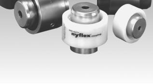
6 ear Couplings Overview Lovejoy/Sier-Bath Nyflex & Mite Lovejoy/Sier-Bath Nylon Couplings are compact and require no lubrication. They operate over a wide temperature range at speeds up to 5,000 RPM and are effectively used in applications such as motor/generator sets, pump sets and many light to medium duty industrial coupling applications. No lubricants are ever required, eliminating the need for seals. The resilient nature of the Nylon material makes the contact of the hubs and sleeves almost frictionless. Not requiring lubrication readily permits the use of these couplings in vertical and blind assembly applications where the sliptogether components offer easy inspection and adjustment. When completely assembled, the Mite coupling weighs less than 1 lb (.45Kg) and the Nyflex only 3.50 lbs (1.59 Kg). Features of mite and nyflex couplings: Molded nylon sleeve. No internal frictional loss or heat buildup. Minimum backlash High ambient temperature allowed. Resistance to dirt, moisture, most chemicals. Low maintenance (no seals, lubricant, retainers). High torque, low inertia. Standard bores are available. 2 Spirolox Retaining Rings Sleeve is securely held on the hubs by these spring-steel retaining rings. Removed in seconds, yet they ll withstand 5,000 lbs end-thrust. Nylon Sleeve Resilient, lightweight, abrasion and corrosion resistant nylon is accurately molded to mesh precisely with hubs. Almost frictionless properties eliminate lubrication need. 2 Hubs Sintered Iron Hubs are standards in the Nyflex & Mite. Teeth are crowned to provide greater misalignment capacity and to prevent gouging of Nylon sleeve. Maintain.13 spacing between hubs. -10
7 ear Couplings Overview Vari-Crown Tooth Form Straight With straight hub teeth, there is a high concentration of load under misaligned conditions. As misalignment increases, more of the load is carried by the ends of the teeth, resulting in premature breakdown and coupling failure. Conventional Crown Some manufacturers use a conventionally crowned hub tooth known by various trade names. Regardless of the nomenclature, however, the contour of the tooth is a segment of an arc. Under all operating conditions, equal or similar contact areas between the hub teeth and the sleeve teeth exist. Lovejoy/Sier-Bath Vari-Crown The Sier-Bath Vari-Crown tooth form has a crown at the center of the tooth which is similar to a conventionally crowned tooth coupling. However, as soon as misalignment occurs, the transmitted torque is carried on a flattened area of the hub tooth which is considerably broader and stronger than the conventionally crowned tooth form. Note the larger contact area and reduced stress area of the Vari-Crown tooth form. Patented Vari-Crown Tooth Form for Long Life Facts It can be shown 1 that bodies with the smallest relative curvature have the largest area of contact under load, or specifically, a body with the largest radius of curvature has the largest area of contact with another body when under load. More importantly, under a given load the bodies with the greater radii of curvature have lower induced surface contact stresses. ear tooth couplings have fewer teeth in contact as misalignment increases. Lower Stresses Lovejoy/Sier-Bath s solution to these facts was the development of the patented Vari-Crown tooth form. The Vari-Crown tooth form is a curve with constantly changing radii of curvature. The tooth contact area under misaligned conditions has a much larger radius of curvature than conventional crowning. The contact area is larger, thus reducing the unit stress. Constant Velocity Power Transmission Lovejoy/Sier-Bath produces the Vari-Crown tooth form by a generating method maintaining the necessary characteristics for conjugate tooth action, which are: 1. Constant normal base pitch at any position on the crowned teeth. 2. Correct pressure angle matching of the normal to the curved surface and the sleeve surface at any position of misalignment. Less Backlash The tooth design requires less backlash for a given angle of misalignment than the conventional or circular arc crown. In many applications this is a desirable feature in a gear tooth coupling. Notes: 1. Hertz s study of contact stresses of curved surfaces. -11
8 ear Couplings Selection Process ear Coupling Selection Process Factors Affecting Selection Following is a list of factors that may have to be considered. No priority can be put on these factors. Factors have to be weighed based on specifications and what is technically, environmentally, and economically feasible. Only a few of these factors will come into play on any one application. Rebore capability. Interchangeability with other brands. Adaptability Special modifications. Bore size capacity. Axial freedom or axial restrictions. Torque capacity. Special seals. Maximum speed capacity. High or low temperature. Special balancing. requirements. Weight or low inertia. Chemical resistance. Previous purchase history. Ease of installation. Availability. Ease of maintenance and Alignment requirements. serviceability. Finding the Right Type of Coupling For any one application you will find that only a few of the factors listed will have a high priority. List those priorities. This will be very helpful in picking the right type of coupling. Selection of Type Refer to ear Coupling Selection Charts shown on pages -15 through -17. These charts summarize all Lovejoy ear Coupling products and show individual product capacities. List the factors that are most important to selection of the right type of coupling. By the process of elimination you will eliminate those types that do not apply to the application. Here are a few examples. 1. If an exact retrofit is required all other types of couplings are eliminated from contention. 2. A retrofit or a close proximity will narrow the choices. 3. High Speed requirements eliminate all non high speed couplings or those that cannot be balanced for the RPM required. 4. Spacer or floating shaft couplings eliminate all other types. 5. Torque or HP/100 RPM requirements sometimes eliminate certain coupling types. For instance, if the application has a required torque of 2,000,000 inch pounds, smaller capacity coupling types would not be considered. Selection of Size Once the best type has been chosen then the coupling size is determined. Make a list of the physical attributes required, using the following list as a guideline: Bore and Keyway Bore tolerances if specified Nominal torque Peak torque a) at startup b) during operation. HP/100 RPM required Nominal RPM Balance tolerances if specified Shaft separation- BSE Driven equipment description, for use in applying a service factor. Shrouded or exposed bolts For modified or engineered couplings more information has to be recorded. Please consult Lovejoy Engineering. Application Service Factors No additional service factor should be applied if the driver side input HP or torque has already compensated for the load characteristics. By knowing the actual torque load we can compare this with the driver side torque available. If there is enough service factor applied to the driver side then match the coupling torque to the driver torque. This may be especially important if the coupling is being used between a speed reducer and the driven machine. After the torque or horsepower is known, a service factor may have to be applied. Refer to page -14 for the ear Coupling Application Service Factors chart. Application service factors are applied in order to give reasonably good life to the coupling to prevent premature wear of gear teeth and do not guarantee that the coupling will last indefinitely. Application service factors cannot compensate for poor alignment, improper selection or overlooked environmental conditions. No amount of application service factor can compensate for having selected the wrong size of coupling. Step by Step Procedure Having considered the preceding, the selection process steps are: 1. Choose the gear coupling series and type that meets the application requirement. 2. Determine the nominal torque in in lbs of your application by using the following formula: Nominal Torque = in lb = (HP x 63025) RPM Nm = (KW x 9550) RPM 3. Find the application in the Application Service Factor chart. Multiply the nominal torque by the application service factor to determine the total required torque. 4. Compare the required torque to the maximum torque capacity found in the ear Coupling Selection chart for the coupling type selected. 5. Check that the maximum bore size and the maximum RPM of the coupling type selected are capable of meeting the application requirements. 6. Specify any special requirements. This includes the BSE dimension for floating shaft and spacer types, shear pin torque, slide coupling detail, and mill motor tapered shaft data. Lovejoy Engineering will assist with any application problem. -12
9 ear Couplings Selection Process ear Coupling Examples Selection Example 1: Flanged Coupling The application is a 400 HP electric motor driving a high pressure centrifugal water pump. RPM is The motor shaft is Pump shaft is A flange type coupling is requested. Step 1: Step 2: Step 3: Step 4: Step 5: Step 6: Step 7: Since a flange type is specified, this eliminates the C series. Choose the F series. Refer to pages -20 and -21 for Flanged Series Double Engagement coupling information. Review of the bore size compatibility shows that Size F 2Z\x is requested to accommodate a shaft requirement. Using the Application Service chart on page -14, notice that the application service factor for centrifugal pumps is 1.0. Check the power capacity. Find the HP/100 RPM required for 400 HP at 3600 RPM. HP HP x 100 = 100 RPM RPM HP 400 x 100 = 100 RPM 3600 = The size F 2Z\x is rated at 90 HP/100 RPM. The coupling may seem too large, but it is needed to accommodate the maximum shaft size of Check the RPM. Size F 2Z\x is rate for 4400 RPM Max. Specify any special requirements, such as shaft fit, coatings, etc. Referring to the ear Coupling Selection chart, the code for this coupling is F (size). Specify F 2Z\x and give the bore and keyway data. All couplings in this series are made with an interference fit in the bore unless otherwise specified. Selection Example 2: Spacer Coupling Assume the same conditions as Example 1 except that a spacer type coupling is required, with a 7 spacer, or dropout. Follow steps 1 through 4, as in example 1, arriving at an F type spacer coupling. See pages -42 for F type spacer couplings. Step 7: Referring to the ear Coupling Selection chart, page -16, the code for a Flanged Series Spacer Coupling is FSPCR. Specify the spacer or BSE dimension needed, the bore and keyway data and the RPM, plus any other special conditions. Selection Example 3: Floating Shaft Coupling The application requires a test stand dynamometer to be driven by a DC motor. The products tested are subject to occasional shock load of not more that 2x running torque and not more often than four times an hour. Design HP 1440 at 1000 RPM, with 3000 RPM maximum. The shafts are 20 apart (BSE) and shaft sizes are and The outside diameter cannot exceed 10, and must be greased packed. Step 1: Step 2: Step 3: Since there is a 20 BSE, this calls for a floating shaft type of coupling. Refer to pages -20, -21, and -36 for Flanged Series Floating Shaft coupling information for a review of bore sizes available. Note that the rigid half of the original coupling mounts on the shafts, and that the maximum bore of the rigid half is greater than that of the flex half. Maximum bore of the size 2Z\x is (rigid); the OD is Determine the HP/100 RPM for the application. HP HP x 100 = 100 RPM RPM HP 1440 x 100 = 100 RPM 1000 = 144 No service factor is listed for dynamometer drives, but the shock load is not high and is infrequent and probably not a a factor in the life of the coupling. Therefore, selection will be based on the 144 HP/100 RPM. Step 4: The size 2Z\x is only rated for 90 HP/100 RPM. Therefore, size 3 with a rating or 150 HP/100 RPM is required. This has an OD of 9.44 (size 3Z\x with a 240 HP/100 RPM rating has an OD of 11 ). Step 5: Since the RPM peaks at 3000, and the BSE is 20, the application must be submitted to engineering. Step 5: Step 6: Check the maximum RPM. This must be submitted to engineering to check the critical frequency for 3,600 RPM operation. Special requirements are the length of the spacer, S=7. Note that the BSE dimension is going to be greater than the S dimension. BSE = S + 2R = x.094 = If the BSE was given as 7 then the actual drop out would have been only 7-2 x.094 or Always be sure that the coupling selected provides for the actual BSE needed. Step 6: Step 7: State any special requirements. Referring to the ear Coupling Selection chart, the code for this coupling is FFS (size). Specify FFS 3 and give the bore and keyway data. All couplings in this series are made with an interference fit in the bore unless otherwise specified. Lovejoy engineering will assist in any application problem. -13
10 ear Couplings Selection Data Application Service Factors for ear Couplings Values contained in the table should be used as a general guide and are to be applied to smooth power sources such as electric motors and steam turbines. For drives involving internal combustion engines add 1.0 to the values listed. Agitators Pure Liquids Liquids Variable Density Blowers Centrifugal Lobe Can Filling Machines Car Dumpers Car Pullers, Intermittent Duty Compressors Centrifugal Reciprocating Multi-Cylinder Single Cylinder Conveyors, Uniformly Loaded or Fed Assembly Belt Screw Conveyors, Heavy Duty Not Uniformly Fed Assembly Belt Oven Reciprocating Screw Shaker Cranes and Hoists Main Hoists Reversing Skip Hoists Trolley Drive Bridge Drive Crushers Ore Stone Dredges Conveyors Cutter Head Drives Maneuvering Winches Pumps Fans Centrifugal Cooling Towers Forced Draft Feeders Screw enerators Not Welding Welding Hammer Mills Laundry Washers Reversing Lumber Industry Barkers Drum Type Edger Feed Live Rolls Log Haul Incline Log Haul Well Type Off Bearing Rolls Planer Feed Chains Planer Tilting Hoist Planer Floor Chains Slab Conveyor Sorting Table Trimmer Feed Machine Tools Bending Roll Punch Press, ear Driven Tapping Machines Main Drives Auxiliary Drives Metal Mills Draw Bench Carriage Draw Bench Main Drive Forming Machines Slitters Table Conveyors Non-Reversing Reversing Wire Drawing & Flattening Machine Wire Winding Machine Metal Rolling Mills Blooming Mills Coilers, hot mill Coilers, cold mill Cold Mills Cooling Beds Door Openers Draw Benches Edger Drives Feed Rolls, Reversing Mills Furnace Pushers Hot Mills Ingot Cars Kick-outs Manipulators Merchant Mills Piercers Pusher Rams Reel Drives Reel Drums Reelers Rod and Bar Mills Roughing Mill Delivery Table Runout Tables Saws, hot & cold Screwdown Drives Skelp Mills Slitters Slabing Mills Soaking Pit Cover Drives Straighteners Tables, transfer & runout Thrust Block Traction Drive Tube Conveyor Rolls Unscramblers Wire Drawing Mills, Rotary Type Ball Dryers & Coolers Hammer Kilns Pebble & Rod Pug Tumbling Barrels Mixers Concrete Mixers, Continuous Concrete Mixers, Intermittent Oil Industry Oil Well Pumping Rotary Kilns Paper Mills Agitators, Mixers Barker Auxiliaries, Hydraulic Barker Mechanical Barking Drum Spur ear Only Beater & Pulper Bleacher Calenders Calenders, Super Chippers Coaters Converting Machines, except Cutters, Platers Conveyors Couch Roll Cutters, Platters Cylinders Disc Refiners Dryers Felt Stretcher Felt Whipper Jordans Line Shaft Log Haul Pulp rinder Press Roll Reel Stock Chests Suction Roll Washers & Thickeners Winders Printing Presses Pumps Centrifugal Reciprocating Single Acting 3 or more Cylinders Double Acting 2 or more Cylinders Rotary, ear Type, Lobe Vane Rubber Industry Mixer Rubber Calender Screens Rotary, Stone or ravel Steering ear Stokers Textile Industry Dryers Dyeing Machinery Windlass
11 ear Couplings Selection Data Lovejoy/Sier-Bath C Continuous Sleeve Series Max. Bore Max. Torque Max. Max. Angular Torque Range Coupling Type Code Page Size Capacity RPM Misalignment No. Range inch mm in-lb Nm (degrees)1 Low Med High Standard C 7 /8/ , ,000 1 (Double Engagement) ,520, , ¹ ₂ X X Flex-Rigid CFR 7 /8/ , ,000 ¹ ₂ X (Single Engagement) ,000 42, ,000 1 /4/4/ Mill Motor CMM 7 /8/ , , ,000 42, ,000 ¹ ₂ X Floating Shaft CFS 7 /8/ , ,000 42,712.0 Note 2 ¹ ₂ X Spacer CSPCR 7 /8/ , ,000 42,712.0 Note 3 ¹ ₂ X Cut-out CCS 7 /8/ , ,000 1 X ,000 42, ,000 ¹ ₂ Shear Pin CSHP 1¹ ₂ Per Customer 6, Specifications 2,100 ¹ ₂ X Notes: 1. These are maximum values. For reasonable life expectancy and low reactionary loads, the misalignment should not exceed C\v for small couplings and Z\x for larger couplings. 2. The maximum RPM of a Floating Shaft coupling set may be determined by the critical speed of the floating shaft itself. 3. Maximum RPM may be determined by dimensions of spacer. -15
12 ear Couplings Selection Data Lovejoy/Sier-Bath F Flanged Sleeve Series Max. Bore Max. Torque Max. Max. Angular Torque Range Coupling Type Code Page Size Capacity RPM Misalignment No. Range inch mm in-lb Nm (degrees)1 Low Med High Standard F , ,000 3 X X (Double Engagement) ,827, ,520 1,800 1¹ ₂ Standard FHD ,008, ,944 2,000 Heavy Duty ,269,000 5,341, ¹ ₂ X X Flex-Rigid FFR , ,000 1¹ ₂ (Single Engagement) ,269,000 5,341, /4/ X X X Floating Shaft FFS , Note 2 3 X X X ,269,000 5,341,130 1¹ ₂ Mill Motor FMM , ,000 3 X ,000 87,746 2,100 1¹ ₂ Sliding Hub FSL , ,000 3 X X FSLX ,008, ,944 2,000 1¹ ₂ Spacer FSPCR , Note 3 3 X X ,008, ,944 1¹ ₂ Rigid-Rigid FRR , ,000 X X ,008, ,944 2,000 0 Notes: 1. These are maximum values. For reasonable life expectancy and low reactionary loads the misalignment should not exceed C\vº for small couplings and Z\xº for larger couplings. 2. The maximum RPM of a Floating Shaft coupling set may be determined by the critical speed of the floating shaft itself. 3. Maximum RPM may be determined by dimensions of spacer. 4. Consult Lovejoy Engineering for Metric Bores over 500 mm. -16
13 ear Couplings Selection Data Lovejoy/Sier-Bath Alloy Steel Series Max. Bore Max. Max. Max. Angular T Coupling Type Code Page Size Torque Capacity RPM Misalignment No. Range inch mm in-lb Nm (degrees) Low Med High 1 Standard FA ,000 1,242 10,000 3 X X (Double Engagement) ,008, ,898 2,200 2 Flex-Rigid FAFR , , /2/ (Single Engagement) , ,898 2,200 1 X X Mill Motor FAMM , ,000 3 X X ,008, ,898 2,200 2 Lovejoy/Sier-Bath All Metal Labyrinth Seal Series Max. Bore Max. Max. Max. Angular Torque Range Coupling Type Code Page Size Torque Capacity RPM Misalignment No. inch mm in-lb Nm (degrees) Low Med High 1 Standard FLA 1 1 /2/ ,000 1,695 12,000 1 X X (Double Engagement) ,512, ,912 3,000 Flex-Rigid FLAFR 1 1 /2/ ,000 1,695 12,000 1 /2/ X X (Single Engagement) ,512, ,912 3,000 Mill Motor FLAMMFR 1 1 /2/ consult 15,000 1, X X engineering 1,512, , ,898 Lovejoy/Sier-Bath Standard Heavy Duty Series Max. Bore Max. Max. Max. Angular Torque Range Coupling Type Code Page Size Torque Capacity RPM Misalignment No. inch mm in-lb Nm (degrees) Low Med High 1 Standard FHD ,900 2,000 X X (Double Engagement) ,300,000 5,340, Flex-Rigid FHDFR ,008, ,900 2,000 X X (Single 4 Engagement) ,300,000 5,340, Dloating Shaft FHDFS ,008, ,900 Note 2 3 / 4/4/ X X Lovejoy/Sier-Bath Nylon Sleeve Series ,300,000 5,340,000 3 / 4/4/ Max. Bore Max. Max. Max. Angular Torque Range Coupling Type Code Page Size Torque Capacity RPM Misalignment No. inch mm in-lb Nm (degrees) Low Med High , X Nyflex Nyflex ,000 Mite Mite X ,000 Notes: 1. These are maximum values. For reasonable life expectancy and low reactionary loads, misalignment per mesh should not exceed C\vº for small couplings and Z\xº for larger couplings. 2. The maximum RPM of a Floating Shaft coupling set may be determined by the critical speed of the floating shaft itself. 3. Consult Lovejoy Engineering for Metric Bores over 500 mm. -17
14 ear Couplings Performance Data After review of the selection process, the examples and the general selection information on pages -12 through -17, you can use the following charts to obtain specific information on torque capability, maximum bore, maximum misalignment, lubrication quantities and weights. For convenience, data is listed in English and metric units. Continuous Sleeve Series (C)...charts 1, 2, 3 Flanged Sleeve Series (F)...charts 4, 5, 6, 7 Flanged Sleeve Series (Heavy Duty or Forged Steel)...charts 8, 9, 10 All Metal Labyrinth Seal Series (FL)...charts 11, 12, 13 Alloy Steel Series (FA)...charts 14, 15, 16, 17 Continuous Sleeve Series Chart 1 Capacity Max. Parallel rease Capacity Size HP Torque Shear Pin Speed Misalignment C 100RPM in-lb Nm Torque Unbal 1 Weight Volume x 10 3 x 10 3 RPM inch mm US Metric US Metric ⁷ ₈ , oz 28 g 2 oz-liq 59 ml 1¹ ₂ , oz 42 g 3 oz-liq 89 ml , oz 78 g 6 oz-liq 178 ml 2¹ ₂ , oz 142 g 12 oz-liq 355 ml , lb 226 g 18 oz-liq 533 ml 3¹ ₂ , lb 340 g 26 oz-liq 770 ml , lb 453 g 1.1 qts 1.1 L 4¹ ₂ , lbs 566 g 1.5 qts 1.4 L Determined By Customer Specifications , lbs 679 g 1.8 qts 1.7 L , lbs 906 g 2.3 qts 2.2 L , lbs 1.1 kg 2.9 qts 2.8 L 9 2,000 1, lbs 2.0 kg 1.3 gal 5.0 L 11 3,500 2, lbs 2.2 kg 1.4 gal 5.2 L 12 4,000 2, lbs 3.0 kg 1.9 gal 7.2 L Notes: 1. Max Speed Balanced Approximately 3 Times Speed Shown Unbalanced 2. Horsepower, Torque, and Parallel Misalignment Capacity for sizes M\, through 3Z\x are based on Z\xº misalignment per gear mesh. 3. Horsepower, Torque, and Parallel Misalignment Capacity for sizes 4 through 12 are based on Z\vº misalignment per gear mesh. Chart 2 Approximate Weight Rough Bore Inertia - Rough Bore Size Flex-Flex Flex-Universal Spacer Cut-out Shifter Shear Pin Flex-Flex Flex-Universal C (mill motor) (cplg only no shaft) (cplg only no spacer) (mill motor) lb kg lb kg lb kg lb kg lb kg lb kg in-lb-sec 2 Nm-sec 2 in-lb-sec 2 Nm-sec 2 ⁷ ₈ N/A N/A ¹ ₂ ¹ ₂ ¹ ₂ ¹ ₂ , Determined by W and OD Dimension -18
15 ear Couplings Performance Data Continuous Sleeve Series Con t. Chart 3 Rough Bore Maximum Bore 1 Size 1 Sq. Key 1 Metric Key C std. or rigid hub shear hub std. hub shear std. shear inch mm inch mm inch inch mm mm ⁷ ₈ N/A N/A N/A 31 N/A 1¹ ₂ ¹ ₂ ¹ ₂ ¹ ₂ Note: 1. Bores and Keyways are standard per AMA 9002-A86 for inch sizes through 9.000; see page ED-17 in Engineering Data section, Metric Bores are per ISO R286 and Keyways are per DIN 6885; see page ED-15 in Engineering Data section. 2. These bores have a reduced keyway. Flanged Sleeve Series Sizes 1 to 9 Chart 4 Capacity Max. Parallel Size HP Torque Speed Misalignment F 100RPM in-lb Nm Unbal 3 x 10 3 x 10 3 RPM in mm , / , , / , , / , , / , , / , , , ,600 1, , ,100 1, , ,900 1, , Notes: 1. Horespower Torque Capacity and Parallel Misalignment Capacity for sizes 1 through 5Z\x, are based on 1Z\xº misalignment per gear mesh and maximum bore. Consult Lovejoy for greater capacity. 2. Horsepower, Torque Capacity and Parallel Misalignment Capacity for sizes 6 through 9 are bases on C\vº misalignment per gear mesh and maximum bore. Consult Lovejoy for greater capacity. 3. For couplings operating at higher speeds, consult Lovejoy engineering. -19
16 ear Couplings Performance Data Flanged Sleeve Series Sizes 1 to 9 con t. Chart 5 Lube Capacity flex-flex Lube Capacity flex-rigid Size Weight Volume Weight Volume F US Metric US Metric US Metric US Metric 1 2 oz 57g 2 oz-liq 59 ml 1 oz 28 g 1 oz-liq 30 ml 1¹ ₂ 4 oz 113 g 4 oz-liq 118 ml 2 oz 57 oz-liq 59 ml oz 163 g 6 oz-liq 178 ml 3 oz 81 oz-liq 89 ml 2¹ ₂ 11 oz 297 g 12 oz-liq 355 ml 5 oz 149 oz-liq 178mL lb 454 g 18 oz-liq 533 ml 0.5 lb 227 oz-liq 266mL 3¹ ₂ 1.3 lbs 568 g 24 oz-liq 710 ml 0.6 lb 284 g 12 oz-liq 355mL lbs 908 g 1.1 qts 1.1 L 1.0 lb 454 g 18 oz-liq 532mL 4¹ ₂ 3.5 lbs 1.59 kg 2.0 qts 1.9 L 1.8 lbs 795 g 1.0 qt 946mL lbs 2.04 kg 2.5 qts 2.4 L 2.3 lbs 1.0 kg 1.3 qts 1.2 L 5¹ ₂ 6.5 lbs 2.95 kg 3.5 qts 3.3 L 3.3 lbs 1.5 kg 1.8 qts 1.7 L lbs 3.29 kg 1.0 gal 3.8 L 3.6 lbs 1.6 kg 0.5 gal 1.9 L lbs 4.20 kg 1.3 gals 4.7 L 4.6 lbs 2.1 kg 0.6 gal 2.4 L 8 18 lbs 7.95 kg 2.3 gals 8.5 L 8.8 lbs 4.0 kg 1.1 gals 4.3 L 9 20 lbs 9.08 kg 2.8 gals 10.4 L 10.0 lbs 4.5 kg 1.4 gals 5.2 L Chart 6 Size F flex-rigid lb kg flex-flex lb kg Approximate Weight-Solid flex-universal rigid-rigid lb kg lb kg Inertia-Solid flex-flex flex-rigid flex-universal rigid-rigid in-lb-sec 2 Nm-sec 2 in-lb-sec 2 Nm-sec 2 in-lb-sec 2 Nm-sec 2 in-lb-sec 2 Nm-sec /2/ 2 1 /2/ /2/ /2/ 5 1 /2/ , , , , , , Chart 7 Rough Bore Maximum Bore 1 Size 1 Sq. Key 1 Red. Key Metric Key F flex hubs rigid hubs flex rigid flex rigid flex rigid inch mm inch mm inch inch inch inch mm mm ¹ ¹ ¹ ¹ ¹ SOLID W/CENTER Note: Bores and Keyways are standard per AMA 9002-A86 for inch sizes through 9.000; see page ED-17 in Engineering Data section. Metric Bores are per ISO R286, and Keyways are per DIN 6885, JS9; see page ED-15 in Engineering Data section
17 ear Couplings Performance Data Flanged Sleeve Series Sizes 7 to 30 Chart 8 Size F FHD Capacity Max. Parallel HP Torque Speed Misalignment Inertia-Solid 100RPM in-lb Nm Unbal 2 flex-flex flex-flex flex-rigid rigid-rigid x 10 6 x 10 6 RPM inch mm in-lb-sec 2 N-M-sec 2 in-lb-sec 2 N-M-sec 2 in-lb-sec 2 N-M-sec 2 1, , , , , , , , , , , , , , , , , , , , , , , , , , , , , , , ,507 1,187 11,731 1,326 12,955 1,464 34, ,369 1,850 18,364 2,075 20,360 2,301 42, ,495 2,768 27,466 3,104 30,437 3,439 52, ,446 3,892 38,988 4,405 43,530 4,919 62, ,800 5,401 53,641 6,061 59,482 6,721 75, ,811 7,097 70,626 7,980 78,442 8,864 Notes: 1. Horsepower, Torque Capacity and Parallel Misalignment Capacity, for sizes 7 through 30 are based on 3 / 4 º misalignment per gear mesh and maximum bore. Consult Lovejoy for greater capacity. 2. For couplings operating at higher speeds consult Lovejoy indicates end cap design. Chart 9 Maximum Bore Flex Hub Maximum Bore Rigid Hub Max. Bore Size 2 Sq. Keys Keyway 2 Red. Keys Keyway 2 Sq. Key Keyway 2 Red. Keys Keyway Metric FHD W H W H W H W H flex rigid inch inch inch inch inch inch inch inch inch inch inch inch mm mm Refer to Lovejoy Note: 1. + indicates end cap design. -21
18 ear Couplings Performance Data Flanged Sleeve Series Sizes 7 to 30 con t. Chart 10 Approximate Weight Solid Lube Capacity flex-flex Lube Capacity flex-rigid Size flex-flex flex-rigid rigid-rigid Weight Volume Weight Volume FHD lb kg lb kg lb kg US Metric US Metric US Metric US Metric , , lbs 4.2 kg 1.3 gal 4.7 L 4.6 lbs 2.1 kg 0.6 gal 2.4 L 8+ 1, , , lbs 7.9 kg 2.3 gal 8.5 L 8.8 lbs 4.0 kg 1.1 gal 4.3 L 9+ 2, , ,241 1, lbs 9.1 kg 2.8 gal 10.4 L 10.0 lbs 4.5 kg 1.4 gal 5.2 L 10 2,500 1,135 2,723 1,236 2,946 1, lbs 11.2 kg 3.5 gal 13.2 L 12.4 lbs 5.6 kg 1.8 gal 6.6 L 11 3,380 1,535 3,640 1,653 3,900 1, lbs 13.5 kg 4.0 gal 15.1 L 14.9 lbs 6.8 kg 2.0 gal 7.6 L 12 4,165 1,891 4,508 2,047 4,851 2, lbs 17.5 kg 5.3 gal 19.9 L 19.3 lbs 8.7 kg 2.6 gal 9.9 L 13 5,215 2,368 5,600 2,542 5,985 2, lbs 20.9 kg 6.3 gal 23.7 L 23.0 lbs 10.4 kg 3.1 gal 11.8 L 14 6,400 2,906 6,837 3,104 7,274 3, lbs 28.3 kg 8.3 gal 31.2 L 31.1 lbs 14.1 kg 4.1 gal 15.6 L 15 7,710 3,500 8,244 3,743 8,778 3, lbs 32.9 kg 9.8 gal 36.9 L 36.3 lbs 16.5 kg 4.9 gal 18.4 L 16 9,250 4,200 9,848 4,471 10,446 4, lbs 39.6 kg 11.8 gal 44.5 L 43.6 lbs 19.8 kg 5.9 gal 22.2 L 18 11,890 5,398 12,673 5,754 13,456 6, lbs 47.2 kg 14.0 gal 53.0 L 52.0 lbs 23.6 kg 7.0 gal 26.5 L 20 16,830 7,641 18,113 8,223 19,396 8, lbs 60.8 kg 18.0 gal 68.1 L 67.0 lbs 30.4 kg 9.0 gal 34.1 L 22 21,970 9,974 23,671 10,747 25,372 11, lbs 79.0 kg 23.0 gal 87.0 L 87.0 lbs 39.5 kg 11.5 gal 43.5 L 24 27,735 12,592 29,958 13,601 32,181 14, lbs 93.5 kg 27.5 gal L lbs 46.8 kg 13.8 gal 52.0 L 26 34,370 15,604 37,104 16,845 39,838 18, lbs kg 33.5 gal L lbs 57.0 kg 16.8 gal 63.4 L 28 40,910 18,573 44,012 19,981 47,114 21, lbs kg 37.0 gal L lbs 63.3 kg 18.5 gal 70.0 L 30 47,470 21,551 51,065 23,184 54,660 24, lbs kg 42.8 gal L lbs 73.1 kg 21.4 gal 80.9 L Notes: 1. + indicates end cap design. -22
19 ear Couplings Performance Data All Metal Labyrinth Seal Series Chart 11 Capacity Max. Parallel Inertia Solid HP Torque Speed Misalignment Size 100RPM in-lb Nm Unbal flex-flex flex-flex flex-rigid rigid-rigid FLA x 10 3 x 10 3 RPM inch mm lb-in-sec 2 N-M-sec 2 in-lb-sec 2 N-M-sec 2 lb-in-sec 2 N-M-sec 2 1¹ ₂ , , ¹ ₂ , , ¹ ₂ , , ¹ ₂ , , ¹ ₂ , , , Chart 12 Lube Capacity Solid Size Volume rease V Oil Flex Flex Flex rigid FLA US Metric US Metric lb kg lbs kg 1¹ ₂ 6 oz-liq 178 ml 2 oz-liq 59 ml oz-liq 237 ml 3 oz-liq 89 ml ¹ ₂ 16 oz-liq 474 ml 5 oz-liq 148 ml oz-liq 710 ml 8 oz-liq 237 ml ¹ ₂ 1.1 qts. 1.1 L 12 oz-liq 355 ml qts. 1.8 L 20 oz-liq 592 ml ¹ ₂ 2.3 qts. 2.1 L 24 oz-liq 710 ml qts. 2.8 L 1.0 qt. 946 ml ¹ ₂ 4.8 qts. 4.5 L 1.6 qts. 1.5 L qts. 5.9 L 1.9 qts. 1.8 L qts. 7.8 L 2.9 qts. 2.7 L Chart 13 Rough Bore Maximum Bore 1 1 Sq. Key Metric Key Size flex flex rigid rigid flex rigid flex rigid FLA inch mm inch mm inch inch mm mm 1¹ ₂ ¹ ₂ ¹ ₂ ¹ ₂ ¹ ₂ Note: 1. Bores and Keyways are per AMA 9002-A86 for inch sizes; see page ED 17 in Engineering Data section, Metric Bores are per ISO R286 and Keyways are per DIN 6885, JS9; see page ED-15 in Engineering Data section. -23
20 ear Couplings Alloy Steel Series Chart 14 Capacity Maximum Parallel Size HP Torque Speed Misalignment FA 100 RPM in-lb Nm Unbal. flex-flex x 10 3 x 10 3 RPM inch mm , / , , / , , / , , / , , / , , , Notes: Chart 16 Size FA /2/ 2 1 /2/ /2/ Chart Horsepower, Torque, and Parallel Misalignment capacity for sizes 1 through 5Z\x are based on 1Z\xº per gear mesh and maximum bore. Consult Lovejoy for greater capacity. 2. Horsepower, Torque, and Parallel Misalignment capacity for sizes 6 and 7 are based on C\vº per gear mesh and maximum bore. Consult Lovejoy for greater capacity. 3. For couplings operating at higher speeds, consult Lovejoy engineering. flex-rigid lb kg , flex-flex lb kg Approximate Weight-Solid flex-universal rigid-rigid lb kg lb kg , Lube Capacity flex-flex Lube Capacity flex-rigid Size Weight Volume Weight Volume FA US Metric US Metric US Metric US Metric 1 2 oz 57g 2 oz-liq 59 ml 1 oz 28 g 1 oz-liq 30 ml 1¹ ₂ 4 oz 113 g 4 oz-liq 118 ml 2 oz 57 oz-liq 59 ml oz 163 g 6 oz-liq 178 ml 3 oz 81 oz-liq 89 ml 2¹ ₂ 11 oz 297 g 12 oz-liq 355 ml 5 oz 149 oz-liq 178mL lb 454 g 18 oz-liq 533 ml 0.5 lb 227 oz-liq 266mL 3¹ ₂ 1.3 lbs 568 g 24 oz-liq 710 ml 0.6 lb 284 g 12 oz-liq 355mL lbs 908 g 1.1 qts 1.1 L 1.0 lb 454 g 18 oz-liq 532mL 4¹ ₂ 3.5 lbs 1.59 kg 2.0 qts 1.9 L 1.8 lbs 795 g 1.0 qt 946mL lbs 2.04 kg 2.5 qts 2.4 L 2.3 lbs 1.0 kg 1.3 qts 1.2 L 5¹ ₂ 6.5 lbs 2.95 kg 3.5 qts 3.3 L 3.3 lbs 1.5 kg 1.8 qts 1.7 L lbs 3.29 kg 1.0 gal 3.8 L 3.6 lbs 1.6 kg 0.5 gal 1.9 L lbs 4.20 kg 1.3 gals 4.7 L 4.6 lbs 2.1 kg 0.6 gal 2.4 L Inertia-Solid flex-flex flex-rigid flex-universal in-lb-sec 2 Nm-sec 2 in-lb-sec 2 Nm-sec rigid-rigid 2 Nm-sec Chart 17 Rough Bore Maximum Bore 1 Size 1 Sq. Key 1 Red. Key Metric Key FA flex hubs rigid hubs flex rigid flex rigid flex rigid inch mm inch mm inch inch inch inch mm mm ¹ ₂ ¹ ₂ ¹ ₂ ¹ ₂ ¹ ₂ Note: Bores and Keyways are standard per AMA 9002-A86 for inch sizes through 9.000; see page ED-17 in Engineering Data Section. Metric bores are per ISO R286 and Keyways are per DIN 6885, JS9; see page ED-15 in Engineering Data Section.

21 ear Couplings Dimensional Data Lovejoy/Sier-Bath Flanged Sleeve Series Draw-off Holes (Optional) asket Vari-Crown Hub Teeth Med. Carbon Steel Hubs & Sleeves Larger Bore Capacity Both Hub Diameters are Identical O Ring Seals Major Diameter Fit Interference Fit Smooth One Piece Sleeve Flanges Available in Both Shrouded and Exposed Bolt Design Heat-Treated Bolts for High Strength Coated for Corrosion Resistance Two Lubrication Plugs in Each Half Sleeve -33

22 ear Couplings Dimensional Data Lovejoy/Sier-Bath Flanged Sleeve Series F Double Engagement (Flex Flex) The standard F is the basis for the other models in the Flanged Sleeve Series. It provides standard double engagement for parallel misalignment, angular misalignment, and end float. Torque Max Speed Maximum Bore Minimum Size Rating Unbalanced sq. key metric key Bore OAL FD D HD LTB BSE CAC n-lbs. RPM inch mm inch inch inch inch inch inch inch inch 1 7,600 6, /2 18,900 5, ,500 5, /2 56,700 4, ,500 4, /2 151,200 3, ,500 3, /2 302,400 2, ,700 2, /2 573,300 2, ,700 2, ,008,400 2, ,323,500 1, ,827,700 1, Notes: 1. Shrouded bolts are standard on sizes 1 through 5 1 / 2. Exposed bolts are standard on sizes 6 through Draw off holes are available at an additional charge on sizes F1 through 3 1 / 2. They are standard on sizes 4 and up. 3. For Performance Data see pages -19 and When ordering, please specify: 1. Required bore diameter of both hubs, with tolerance. 2. Sizes of keyways, if desired. Set screws not supplied unless specified. 3. Speed and Horsepower of driving unit.
23 ear Couplings Dimensional Data Lovejoy/Sier-Bath Flanged Sleeve Series Standard Heavy Duty Type FHD Double Engagement (Flex Flex) Similar in design to the standard F, these larger sizes satisfy high-torque low-speed applications such as those that occur in mill operations. Torque Max Speed Maximum Bore Size Rating Unbalanced 2-sq. Keys OAL FD D HD LTB BSE FHD in-lbs. RPM inch inch inch inch inch inch inch 7+ 1,008,400 2, ,323,500 1, ,827,700 1, ,521,000 1, ,466,000 1, ,412,000 1, ,294,000 1, ,429,000 1, ,752, ,454, ,605, ,017, ,429, ,471, ,773, ,076, ,269, Notes: 1. + indicates end cap seal design as shown. Specify FHD and size for this design, otherwise these sizes will be supplied as shown on page Exposed bolts are standard on sizes 7 through For Performance Data see pages -21 and -22. When ordering, please specify: 1. Required bore diameter of both hubs, with tolerance. 2. Sizes of keyways, if desired. Set screws not supplied unless specified. 3. Speed and Horsepower of driving unit. -35

24 ear Couplings Dimensional Data Lovejoy/Sier-Bath Flanged Sleeve Series Flex Rigid and Floating Shaft Type FFR and FFS Single Engagement (Flex-Rigid) Single Engagement type couplings consist of a flexible and a rigid half. These couplings only accommodate angular misalignment. Single Engagement type gear couplings are most commonly used in floating shaft applications. The floating shaft configuration allows removal of the center assembly for ease of maintenance without repositioning machinery. Also, rigid hubs can accommodate larger shaft diameters than the flex hub when additional bore capacity is required. Single Engagement Flex-Rigid (FFR) Floating Shaft (FFS) aximum Bor M ximum Bor M nimum Bor ize o que ax Speed lex Hu R gid Hub FR ating nbalanced q. key etric key q. key etric key lex Hu R gid Hub AL D H LTB T 1 SE AC FS n-lbs. PM nch m nch m nch nch nch nch nch nch nch nch nch nch,600, /2 8,900, ,500, /2 6,700, ,500, /2 51,200, ,500, /2 02,400, ,700, /2 73,300, ,700, ,008,400, ,323,500, ,827,700, olid w/center Notes: 1. Shrouded bolts are standard on sizes 1 through 5 1 / 2. Exposed bolts are standard on sizes 6 through FFR is used for Single Engagement Flex-Rigid. 3. FFS is used for Floating Shaft. 4. For Performance Data see pages -19 and When ordering, please specify: 1. Required bore diameter of both hubs, with tolerances. 2. Indicate which bore is for Flex Hub and which is for Rigid Hub. 3. Sizes of keyways, if desired. Set screws not supplied unless specified. 4. Speed and horsepower of driving unit. 5. If two Single Engagement couplings are to be used as a Floating Shaft set, submit drawing if available. 6. Shaft separation exact distance between connected shaft ends required if floating shaft is to be supplied by Lovejoy. 7. Floating Shaft type supplied less shaft unless otherwise specified.
25 ear Couplings Dimensional Data Lovejoy/Sier-Bath Flanged Sleeve Series Heavy Duty Flex Rigid and Floating Shaft Type FHDFR and FHDFS Single Engagement (Flex-Rigid) Similar in design to the standard Flex-Rigid, these larger sizes satisfy high-torque low-speed applications such as those that occur in mill operations. FHDFR FHDFS aximum Bor M ximum Bor ize orque ax Speed -sq. Keys -sq. Keys HDFR ating nbalanced lex Hu R gid Hub AL D H LTB T 1 SE HDFS n-lbs. nch nch nch nch nch nch nch nch nch +,008,400, ,323,500, ,827,700, ,521,000, ,466,000, ,412,000, ,294,000, ,429,000, ,752, ,454, ,605, ,017, ,429, ,471, ,773, ,076, ,269, Notes: 1. + indicates end cap seal design as shown. Specify FHDFR or FHDFS and size for this design, otherwise these sizes will be supplied as shown on page Exposed bolts are standard on sizes 7 through For Performance Data see pages -21. When ordering, please specify: 1. Required bore diameter of both hubs, with tolerances. 2. Sizes of keyways, if desired. Set screws not supplied unless specified. 3. Speed and Horsepower of driving unit. -37

26 ear Couplings Dimensional Data Lovejoy/Sier-Bath Flanged Sleeve Series Mill Motor Type FMM Designed specifically for mill type motors with tapered shafts. The sleeves and one hub are standard, the other hub is taper bored to customer spec ifications and cut off for the nut on end of the motor shaft. orque ax Speed aximum Bor M nimum T ize ating nbalanced q. key etric key ore AL D H LTD x. SE MM n-lbs.. PM ch m ch ch ch ch ch ch ch ch,600, /2 8,900, ,500, /2 6,700, ,500, /12 51,200, ,500, /2 02,400, ,700, /2 73,300, ,700, Notes: 1. LTB1 Dimensions shown are maximum lengths of Universal Hubs kept in stock and altered to customer s specifications. Longer length hubs are made to order. 2. Dimension 1 shown on page For Performance Data see pages -19 and -20. When ordering, please specify: 1. Required bore diameter of both hubs, with tolerance. Include dimensions of large end and small end of bore. 2. Taper per foot and length of tapered portion of shaft. 3. Sizes of keyways, if desired. Specify if they are parallel to the center line of the shaft or parallel to the bore. Set screws not supplied unless specified. 4. Speed and horsepower of driving unit. 5. Specify counter bore dimensions if desired. 6. Submit drawing if available. 7. Mill motor frame size if applicable. -38

27 ear Couplings Dimensional Data Lovejoy/Sier-Bath Flanged Sleeve Series Mill Motor Type FMM MM Hub Size AISE OAL LTB LTB1 1 TB 2 Keyway Frame W H FMM No. inch inch inch inch inch inch inch 1¹ ₂ 602/ / / / / / ¹ ₂ 603/ / / / / / / / ¹ ₂ 608/ / / / / / / / / ¹ ₂ 614/ / / / / / ¹ ₂ 616/ / / / Notes: 1. + indicates that a counterbore is required. 2. Bore taper is 1Z\v per foot on diameter 3. For Performance Data see pages -19 to
28 ear Couplings Dimensional Data Lovejoy/Sier-Bath Flanged Sleeve Series Slide Type FSL By utilizing standard and/or modified gear coupling parts, Slide couplings can be assembled to suit a wide range of axial movement. The basic coupling consists of two long tooth sleeve assemblies, standard hubs and/or modified mill motor hubs and a center plate. The plates are provided with lube holes so that both halves of the coupling will be adequately lubricated. OAL OAL1 LTB1 L2 Torque Max Speed Maximum Bore Minimum 1 Hub 2 Hu TB slide L1 slide BSE Size Rating Unbalanced sq. key metric key Bore Reversed FD D HD std. hub std. half min. AP Max. 1 FSL in-lbs. RPM inch mm inch inch inch inch inch inch inch inch inch inch inch 1 7,600 6, /2 18,900 5, ,500 5, /2 56,700 4, ,500 4, /12 151,200 3, ,500 3, /2 302,400 2, ,700 2, /2 573,300 2, ,700 2, ,008,400 2, Notes: 1. AP Max. = Maximum slide per half coupling. 2. Shrouded bolts are standard on sizes 1 through 5 1 / 2. Exposed bolts are standard on sizes 6 & For Performance Data see pages -19 and -20. When ordering, please specify: 1. Required bore diameter of both hubs, with tolerances. 2. Sizes of keyways, if desired. Set screws not supplied unless otherwise specified. 3. Speed, horsepower, and application details. 4. Amount of slide required. 5. Maximum minimum shaft separation. -40
29 ear Couplings Dimensional Data Lovejoy/Sier-Bath Flanged Sleeve Series Long Slide Type FSLX By utilizing standard and/or modified gear coupling parts, Slide couplings can be assembled to suit a wide range of axial movement. The basic coupling consists of a standard half and a custom designed long slide half. A center plate is provided with lube holes so that both halves of the coupling will be adequately lubricated. AP2 AP3 Torque Max Speed Maximum Bore Minimum AP1 max. Max. 3 Max. 4 Size Rating Unbalanced sq. key metric key Bore OAL FD D HD LTB LTB2 HL L1 L2 long slid lid e FSLX in-lbs. RPM inch mm inch inch inch inch inch inch inch inch inch inch inch inch inch inch 1 1/2 18,900 5, ,500 5, /2 56,700 4, ,500 4, /12 151,200 3, ,500 3, /2 302,400 2, ,700 2, /2 573,300 2, ,700 2, ,008,400 2, Notes: 1. Shrouded bolts are standard on sizes 1 1 / 2 through 5 1 / 2. Exposed bolts are standard on sizes 6 and Longer slide available in all sizes. Consult Lovejoy. 3. AP2 Max. = Standard half with slide one side, long slide other. 4. AP3 Max. = Both halves with long slide. 5. For Performance Data see pages -19 and -20. When ordering, please specify: 1. Required bore diameter of both hubs, with tolerances. 2. Sizes of keyways, if desired. Set screws not supplied unless otherwise specified. 3. Speed, horsepower, and application details. 4. Amount of slide required. 5. Maximum minimum shaft separation. 6. HL dimension. 7. LTB2 dimension. -41

30 ear Couplings Lovejoy/Sier-Bath Flanged Sleeve Series Spacer Type FSPCR Spacer ear couplings allow additional spacing between shafting where ease of maintenance is required. The spacer allows a number of service functions to be performed while providing room for the removal of the standard coupling half from the shaft without moving the driver or driven units. Dimensional Data This coupling consists of standard full-flex hubs and sleeve assemblies bolted to a flanged spacer. Thus, a wide variety of shaft spacings can be accommodated. Consult Lovejoy for price and delivery for shaft spacings. This coupling has angular and parallel misalignment capabilities in addition to end float. Torque Maximum Bore Minimum Size Rating sq. key metric key Bore OAL FD D HD LTB BSE CAC D1 D2 S FSPCR in-lbs. inch mm inch inch inch inch inch inch inch inch inch inch inch inch 1 7, /2 18, , /2 56, , /12 151, , /2 302, , /2 573, , ,008, Determined by Shaft Separation Determined by Customer Specifications Determined by Shaft Separation Determined by Shaft Separation Notes: 1. Shrouded bolts are standard on sizes 1 1 / 2 through 5 1 / 2. Exposed bolts are standard on sizes 6 and For Performance Data see pages -19 to -20. When ordering, please specify: 1. Required bore diameter of both hubs, with tolerances. 2. Sizes of keyways, if desired. Set screws not supplied unless specified. 3. Speed, horsepower and application details. 4. Length of spacer or distance between ends of shafts to be connected. 5. Submit drawing if available. -42
31 ear Couplings Dimensional Data Lovejoy/Sier-Bath Flanged Sleeve Series Limited End Float Type FLEF The Limited End Float ear coupling is used where axial movement must be limited. It is predominately used where end float must be restricted and maintained. For example, in sleeve bearings and rotor systems where thrust is not permitted, the coupling must maintain the position of driving units and driven units. This coupling uses standard full-flex components with the addition of a steel plate to limit the movement. There is an optional plate with flow-through lube holes. orque ax Speed aximum Bor M nimum ize ating nbalanced q. key etric key ore AL D H LTD e SE T LEF n-bls. PM ch m ch ch ch ch ch ch ch ch ch,600, /2 8,900, ,500, /2 6,700, ,500, /12 51,200, ,500, /2 02,400, ,700, /2 73,300, ,700, ,008,400, Notes: 1. F is total end float. (May be modified.) 2. Shrouded bolts are standard on sizes 1 through 5 1 / 2. Exposed bolts are standard on sizes 6 and For Performance Data see pages -19 and -20. When ordering, please specify: 1. Required bore diameter of both hubs, with tolerances. 2. Sizes of keyways, if desired. Set screws not furnished unless otherwise specified. 3. Speed, horsepower and application details. 4. Amount of thrust on either or both shafts. 5. Amount of end float required. 6. Submit drawing if available. -43
32 ear Couplings Dimensional Data Lovejoy/Sier-Bath Flanged Sleeve Series Rigid Rigid Type FRR Rigid-Rigid type couplings provide a convenient means of rigidly connecting shafts on applications which require no flexing within the coupling. The allsteel construction offers torque capacities which exceed those of mild steel shafts to be coupled. Flanged style hubs are used with shrouded rade 5 bolts. Hubs with exposed bolts are available. Rigid coupling halves are used with other style couplings. One such configuration is the Single Engagement Flex-Rigid coupling. Torque Max Speed Maximum Bore Minimum Bore Size Rating Unbalanced sq. key metric key Rigid Hub OAL FD HD LTB BSE FRR in-lbs. RPM inch mm inch inch inch inch inch 1 7,600 6, /2 18,900 5, ,500 5, /2 56,700 4, ,500 4, /12 151,200 3, ,500 3, /2 302,400 2, ,700 2, /2 573,300 2, ,700 2, ,008,400 2, Solid w/centers Notes: 1. Shrouded bolts are standard on sizes 1 through 5 1 / 2. Exposed bolts are standard on sizes 6 and Length of one rigid hub equals one half of OAL. 3. For Performance Data see pages -19 and -20. When ordering, please specify: 1. Required bore diameter of both hubs, with tolerances. 2. Sizes of keyways, if desired. Set screws not furnished unless otherwise specified. 3. Speed, horsepower and application details. 4. Submit drawing if available. -44
33 ear Couplings Dimensional Data Lovejoy/Sier-Bath Flanged Sleeve Series Special Couplings Limited End Float Spacer The addition of plates restricts axial travel of the drive or driven shaft. The spacer makes it possible to remove the hubs from either shaft without disturbing the connected units. Vertical Floating Shaft The lower coupling has a hardened crowned button inserted in the plate of the lower hub. The entire floating assembly rests on this button. Optional construction of upper coupling would be a flexible hub on the floating shaft with a rigid hub on top. Vertical This coupling has the same horsepower, RPM and misalignment capacities as standard couplings of corresponding sizes. A plate with a hardened crowned button rests on the lower shaft which supports the weight of the sleeve. Jordan Used on Jordan machines and refiners, this design is similar to the slide type, except the long hub is split and secured to the shaft with a bolt clamp. This permits quick axial adjustment of the Jordan shafts in this hub. Insulated Use of a special non metallic material between flanges and around bolts prevents passage of stray currents from one shaft to the other. -45
 Single Engagement Flex-Rigid (FR) Size Torque Max Speed Maximum Bore Minimum C/L-C/L Draw-off FLA Rating Unbalanced sq.")
34 ear Couplings Dimensional Data Lovejoy/Sier-Bath All-Metal Labyrinth Seal Series Standard Type FLA and FLAFR Fully interchangeable with industry standard, the FL uses an all metal labyrinth seal. It is made from 4140 alloy steel. Double Engagement Flex-Flex (FF) Single Engagement Flex-Rigid (FR) Size Torque Max Speed Maximum Bore Minimum C/L-C/L Draw-off FLA Rating Unbalanced sq. key metric key Bore FD D HD HD1 BSE BSE1 LTB LTB1 OAL OAL1 W HL of teeth Holes FLAFR in-lbs. RPM inch mm inch inch inch inch inch inch inch inch inch inch inch inch inch inch inch 1 1/2 15,000 12, / ,500 9, / /2 69,250 7, / ,875 6, / /2 188,750 6, / ,750 5, / /2 393,750 4, ,250 4, /2 732,500 3, ,500 3, ,512,500 3, /4-7 Notes: 1. Series FLA are furnished with exposed bolt unless otherwise specified. 2. Draw-off holes are available at an additional charge on sizes 1 1 / 2 through 3 1 / 2. They are standard on sizes 4 and up. 3. For Performance Data see page -23. When ordering, please specify: 1. Required bore diameter of both hubs, with tolerance. 2. Sizes of keyways, if desired. Set screws not supplied unless specified. 3. Speed and Horsepower of driving unit. -46
35 ear Couplings Dimensional Data Lovejoy/Sier-Bath All-Metal Labyrinth Seal Series Mill Motor Type FLAMM and FLAMMFR M Hub ize.i.s.e. e wa LMM rame L2 L3 T LTB1 TB2 T LMMFR o. nch nch nch nch nch nch nch nch nc ¹ 02/ / / / / ¹ 03/ / / / / / / / / / / ¹ 06/ / / / / / / / / / / / ¹ 14/ / / / / / / / ¹ 18/ FLAMM FLAMMFR Notes: 1. Bore taper is 1Z\v per foot on diameter. 2. For Performance Data see page

36 ear Couplings Dimensional Data Lovejoy/Sier-Bath Alloy Steel Series Standard Type FA Double Engagement (Flex-Flex) Interchangeable with all other industry standard couplings, it is available in exposed bolts and shrouded bolts. Can be furnished as special. Angular misalignment is possible up to 1 1 / 2 º per gear mesh. FA Series Couplings are made of 4140 Alloy Steel. Fully molded seals maintain proper lubricant retention during misaligned conditions. Torque Max Speed Maximum Bore Minimum Size Rating Unbalanced sq. key metric key Bore OAL FD D HD LTB BSE CAC FA in-lbs. RPM inch mm inch inch inch inch inch inch inch inch 1,300 6, /2 22,700 5, ,000 5, /2 69,300 4, ,000 4, /2 177,000 3, ,400 3, /2 354,000 2, ,600 2, /2 670,700 2, ,100 2, ,179,300 2, Notes: 1. Shrouded bolts are standard on sizes 1 through 5 1 / 2. Exposed bolts are standard on sizes 6 through For Performance Data see page -24. When ordering, please specify: 1. Required bore diameter of both hubs, with tolerance. 2. Sizes of keyways, if desired. Set screws not supplied unless specified. 3. Speed and Horsepower of driving unit. -48
37 ear Couplings Lovejoy/Sier-Bath Rigid Adjustable Coupling The RA/RAHS series of couplings features axial positioning of the pump impeller in vertical pump applications. The clearance fit bores with keyway allow for easy installation and maintenance for the pump and/or motor. We offer two different styles; 1) Type II Coupling consisting of two Rigid Hubs, Adjusting Nut and Split Ring for Motor hub 2) Type IV Coupling consisting of two Rigid Hubs, Adjusting Nut, Split Ring for Motor hub and Spacer. The RA type coupling meets standard tolerances and the RSHS conforms to API 610 8th edition tolerances. Benefits: Easily Adjustable for Vertical Clearance. AISI 1045 Steel. Removable Spacer for Easy Maintenance. Stainless Steel Coupling Also Available. Parts List Item Description 01 Upper Hub Motor 02 Lower Hub Pump 03 Spacer 04 Adjusting Nut 05 Washer, Split 06 RA & RAHS Accessory Kit 07 RA Accessory Kit Lovejoy/Sier-Bath Flanged Sleeve Series Rigid Adjustable Type RA & RAHS Thrust Maximum Bore Minimum STD OAL S Size HP/100 Capacity sq. key metric key Bore Type II Type IV FD D LTB LTB1 LS DC N SL D1 D2 STD MIN Bolts B.C. RA & RAHS RPM lbs. inch mm inch inch inch inch inch inch inch inch inch inch inch inch inch inch inch Diameter , / , / , / , / , / , / , / , , NO STD , NO STD NO STD , NO STD / , NO STD / Notes: Exposed bolts are standard on all sizes. When ordering, please specify: 1. Required bore diameter of both hubs, with tolerances. 2. Sizes of keyways, if desired. 3. Speed, horsepower and application details. 4. Amount of thrust on either or both shafts. 5. Submit drawing if available. -49

38 ear Couplings Dimensional Data Lovejoy/Sier-Bath Nylon Sleeve Series Nyflex & Mite Lovejoy/Sier-Bath Nylon couplings are compact and require no lubrication. They operate over a wide temperature range at speeds up to 5,000 RPM and are effectively used in applications such as Motor/enerator sets, pump sets, and many light to medium duty industrial coupling applications. No lubricants are ever required, eliminating the need for seals. The resilient nature of the nylon material makes the contact of the hubs and sleeves almost frictionless. Not requiring lubrication readily permits the use of these couplings in vertical and blind assembly applications where the slip-together components offer easy inspection and adjustment. Operationally, the coupling offers a minimum backlash solution that will operate in ambient temperature environments up to -40º F to 150º F. The Nylon Sleeve coupling has a precision molded sleeve and hubs with no bolts, pins, flanges, or protrusions to affect balance or safety. The nylon sleeve permits misalignment up to 5º for the Nyflex and 3º for the Mite. When completely assembled, the Mite coupling weighs less than 1lb and the Nyflex only 3.50 lbs. 2 Spirolox Retaining Rings Sleeve is securely held on the hubs by these spring-steel retaining rings. Removed in seconds, yet they ll withstand 5,000 lbs endthrust. Nylon Sleeve Resilient, lightweight, abrasion and corrosion resistant nylon is accurately molded to mesh precisely with hubs. Almost frictionless properties eliminate lubrication need. 2 Hubs Sintered iron is standard in the Nyflex and Mite. Teeth are crowned to provide greater misalignment capacity and to prevent gouging of Nylon sleeve. Maintain.13 spacing between hubs. Certain acids and alkalis are harmful to Nylon. If in doubt about your application, contact Lovejoy Engineering. Speeds to 5,000 rpm Speed RPM ,000 1,150 1,500 1,750 2,000 2,500 3,000 3,500 4,000 5,000 Nyflex H.P Torque (in-lbs) 1,420 1,190 1,125 1, H.P Mite Torque (in-lbs) Clearance Fit Interference Fit Bore sizes available from stock Nyflex Mite Bore Size Keyway Bore Size Keyway 3 /8 rough none 5 /16 rough none /8 x 1 / 16 3 /16 x 3 / 32 3 /16 x 3 / 32 3 /16 x 3 / 32 1 /4 x 1 / 8 1 /4 x 1 / 8 1 /4 x 1 / 8 1 /4 x 1 / 8 1 /4 x 1 / 8 5 /16 x 5 / 32 5 /16 x 5 / 32 3 /8 x 3 / 16 3 /8 x 3 / 16 3 /8 x 3 / /8 x 1 / 16 3 /16 x 3 / 32 3 /16 x 3 / 32 3 /16 x 3 / 32 1 /4 x 1 / 8 1 /4 x 1 / 8 1 /4 x 1 / 8 All Bore Tolerances are +.001/-.000 up to 1.25 Dimensions Coupling Nyflex Mite OAL LS OD Blind Assembly The no-lubrication feature of Lovejoy/Sier-Bath Nylon Sleeve couplings readily permits their use in vertical applications and for blind assembly. To install, mount both hubs on the shafts; then place the sleeve with a ring in the center groove over one hub. When the connected unit is placed in position, the coupling is fully installed. HD LTB BSE Weight lbs 3.50 <
Gear Coupling. Applications
 Gear Coupling Applications Power Transformation Print & Paper Industries Gear Boxes Textile Industries Conveyors Pumps Compressors Process, Chemical & Pharmaceutical Industries Nylon Gear Couplings Nylon
Gear Couplings G G-1
 ear Couplings -1 ear Couplings eneral Overview Lovejoy/Sier-Bath ear Couplings Lovejoy offers a variety of designs and models in its gear coupling family. From standard, off-the-shelf stock to new, high
Gear Couplings SAFETY WARNING
 ear Couplings! SAFETY WARNIN When using Lovejoy products, you must follow these instructions and take the following precautions. Failure to do so may cause the power transmission product to break and parts
Gear Couplings G-2 CONTINUOUS SLEEVE GEAR COUPLING FLANGED SLEEVE GEAR COUPLING
 Lovejoy/Sier-Bath Lovejoy offers a variety of designs and models in its gear coupling family. From standard, off-the-shelf stock to new, high speed, special designs, Lovejoy can satisfy your gear coupling
Universal Joints. In This Section: D Type HD Type D Type Stainless NB (Needle Bearing) Type LOJ Type DD and DDX Type Universal Joint Boots
 Type LOJ Type DD and DDX Type Universal Joint Boots") JW Universal Joints In This Section: D Type HD Type D Type Stainless NB (Needle Bearing) Type LOJ Type DD and DDX Type Universal Joint Boots www.lovejoy-inc.com 329-1 JW Universal Joints Safety Warning
JW Universal Joints In This Section: D Type HD Type D Type Stainless NB (Needle Bearing) Type LOJ Type DD and DDX Type Universal Joint Boots www.lovejoy-inc.com 329-1 JW Universal Joints Safety Warning
Gear. In This Section: C Types Continuous Sleeve Nyflex and Mite Dentex F Types Flanged Sleeve R Types Rigid Adjustable Coupling Grease
 JW ear In This Section: C Types Continuous Sleeve Nyflex and Mite Dentex F Types Flanged Sleeve R Types Rigid Adjustable Coupling rease www.lovejoy-inc.com 115-1 JW ear Safety Warning When using Lovejoy
Specialty Couplings. Overview. Deltaflex Coupling Design Lovejoy offers maximum misalignment capacity with the Deltaflex coupling! SP-3.
 Overview Deltaflex Coupling Design Lovejoy offers maximum misalignment capacity with the Deltaflex coupling! The Deltaflex coupling is the real solution to installation, misalignment, and performance problems.
Power Transmission Products. Maurey Couplings. Hi-Flex Tire Couplings Hi-Q Jaw Couplings Finished Bore Sleeve Couplings Rigid Bushed Sleeve Couplings
 Power Transmission Products Maurey Couplings Hi-Flex Tire Couplings Hi-Q Jaw Couplings Finished Bore Sleeve Couplings Rigid Bushed Sleeve Couplings Hi-Q Flexible Couplings R to enable full power transmission
FLEXIBLE JAW COUPLINGS
 To order this part, call Lifco Hydraulics USA Toll Free at -800-92-849 Jaw Type Couplings USA Standard The Jaw Type Couplings from Vescor are offered in the industry s largest variety of stock bore/keyway
Jaw Type JW JW-1. Polígono Indutrial O Rebullón s/n Mos - España -
 -1 Overview Couplings USA Standard Elastomer-in-Compression The couplings from Lovejoy are offered in the industry s largest variety of stock bore/keyway combinations. These couplings require no lubrication
A SERIES ELASTOMER COUPLINGS
 A Retaining ring with locking feature B Wrap-around elastomeric insert C Hubs (blank or bored) D Anti-corrosion treatment A B C C D Spacer Arrangement Shown Product Description A Series elastomer couplings
Jaw. In This Section:
 Jaw In This Section: L Type LC Type Al Type - Aluminum SS Type - Stainless RRS and RRSC Types - Spacer C and H Type - Medium / Heavy Duty RRC Type - Spacer www.lovejoy-inc.com 13-1 Jaw Safety Warning When
Jaw Type. Overview. Jaw Type Couplings USA Standard Elastomer-in-Compression
 -1 Overview Jaw Type Couplings USA Standard Elastomer-in-Compression The Jaw Type couplings from Lovejoy are offered in the industry s largest variety of stock bore/keyway combinations. These couplings
High Performance Gear Couplings
 Overview -1 Overview Lovejoy High Speed and Engineered Special Gear Couplings The High Performance group of gear couplings consists of coupling designs that require additional engineering. While standard
Size 1120, Bore Ø0.75" Size 1320, Bore Ø1.25" Size 1420, Bore Ø1.375" 3/4HP. Size 1320, Bore Ø1.25" Size 1320, Bore Ø1.25" Size 1633, Bore Ø2.
 Product Range Hollow Shaft Type Selections shaded in blue offer an increased service factor. Please refer to the gearmotor selection tables for specific unit service factor details. Nominal Ratio (:1)
L-Jaw Elastomeric Couplings
 L-Jaw Elastomeric Couplings F3 100% interchangeable with industry standard 3 Insert materials available 3 Hub materials available Large selection of sizes P-1686-TBW 4/16... TB Wood s 888-829-6637 F3-1
Speed Reducers and Gearmotors
 and Gearmotors Table of Contents 1. General Information 2. How to Select...2.2 Configure a Model Number (Nomenclature)...2.4 AGMA Load Classifications...2.6...2.8 Single Reduction,,, Y3, Y5,...2.8 Single
U-DISC 6-BOLT UNITIZED SPACER DISC COUPLING
 U-DISC 6-BOLT UNITIZED SPACER DISC COUPLING THE U-DISC 6-BOLT UNITIZED SPACER DISC COUPLING Same Day Shipping Stocked in Two Convenient Locations Simple 3-Piece Spacer Disc Coupling Factory Pre-Assembled
Flange Flexible Couplings.
 Flange Flexible Couplings Coupling Selection Coupling Selection How to Select Standard Selection The Standard Selection may be used for engine driven, motor, or turbine applications. The following information
Thomas Flexible Disc Couplings (Metric)
") Disc Catalog Download most up-to-date versions at www.rexnord.com Thomas Flexible Disc s (Metric) Table Of Contents DESCRIPTION PAGE Application Guide................................................................................................................
Disc Catalog Download most up-to-date versions at www.rexnord.com Thomas Flexible Disc s (Metric) Table Of Contents DESCRIPTION PAGE Application Guide................................................................................................................
Thomas Flexible Disc Couplings (Inch)
") Disc Catalog Download the most up-to-date version at www.rexnord.com/documentation Thomas Flexible Disc s (Inch) Table Of Contents DESCRIPTION PAGE Application Guide................................................................................................................
Disc Catalog Download the most up-to-date version at www.rexnord.com/documentation Thomas Flexible Disc s (Inch) Table Of Contents DESCRIPTION PAGE Application Guide................................................................................................................
Thomas Flexible Disc Couplings (Metric)
") Disc Catalog Download the most up-to-date version at www.rexnord.com/documentation Thomas Flexible Disc s (Metric) Table Of Contents DESCRIPTION PAGE Application Guide................................................................................................................
Disc Catalog Download the most up-to-date version at www.rexnord.com/documentation Thomas Flexible Disc s (Metric) Table Of Contents DESCRIPTION PAGE Application Guide................................................................................................................
GASKETS O-RING SEALS FINISHED BORE AND KEYWAY ON REQUEST DETACHABLE SEAL HOLDERS FOR EASY ASSEMBLY & DISASSEMBLY SELF - LOCKING SCREWS FORGED STEEL
 escogear FLEXIBLE GEAR COUPLINGS SERIES C and C... M The most compact solution Maximum torque: up to 174 000 Nm Bores: up to 290 mm O-RING SEALS GASKETS FORGED STEEL CONTINUOUS SLEEVE WITH INTERNAL STRAIGHT
Jaw. In This Section:
 Jaw In This Section: L Type LC Type Al Type - Aluminum SS Type - Stainless RRS and RRSC Types - Spacer C and H Type - Medium / Heavy Duty RRC Type - Spacer www.lovejoy-inc.com 13-1 Jaw Safety Warning When
Specialty Couplings SP SP SP-1
 -1 Overview Unique Coupling Families Deltaflex The patented Deltaflex series of couplings offer maximum misalignment capabilities with negligible reactionary load, for longer equipment life. This all-metal
INDEX SECTION : M GRID COUPLING SECTION : N GEAR COUPLING SECTION :OJAWCOUPLING
 INDEX PAGE # SECTION : M GRID COUPLING GRID COUPLING Selection Procedure M 1 Coupling Selection based on Equivalent hp Ratings M 2-3 Service Factor M 4 Grid Coupling Type T-10 M 5 Grid Coupling Type T-20
High Performance Gear
 JW High Performance Gear In This Section: FHS Type - High Speed Close Coupled FHSA Type - High Speed Standard FHSAA Type - High Speed Precision FHSPAA Type - High Speed Ultra Precision FHSMA Type - High
Catalog April Metric Motorized Torque-Arm II Technical catalog
 Catalog April 2015 Metric Motorized Torque-Arm II Technical catalog With expertise, and a comprehensive portfolio of products and life-cycle services, we help value-minded industrial customers improve
Dura-Flex Couplings FEATURES
 Dura-Flex Couplings F2 Patent No. 5,611,732 The specially designed split-in-half element can be easily replaced without moving any connected equipment. FETURES Designed from the ground up using finite
Series P Planetary. Technical Up to - 90kW / 65000Nm. Planetary CP-2.00GB0 1
 VARIMAX AG, Antriebstechnik, Normannenstrasse 14, Postfach 762, CH-3018 Bern Tel. +41 (0)31 990 00 70 e-mail info@varimax.ch Fax +41 (0)31 990 00 71 web www.varimax.ch Series P Planetary Technical Up to
Grid. In This Section: FOR MORE INFORMATION CALL CLARK VISIT OUR WEB SITE AT
 JW In This Section: Horizontal Cover Style Vertical Cover Style Full Spacer Style Half Spacer Style www.lovejoy-inc.com 213-1 JW Safety Warning When using Lovejoy products, you must follow these instructions
Falk Steelflex Grid Couplings (Metric)
") Grid Coupling Catalog Download the most up-to-date versions at www.rexnord.com Falk Steelflex Grid Couplings (Metric) Table Of Contents DESCRIPTION PAGE Falk Steelflex Grid Coupling Application Guide...3
Grid Coupling Catalog Download the most up-to-date versions at www.rexnord.com Falk Steelflex Grid Couplings (Metric) Table Of Contents DESCRIPTION PAGE Falk Steelflex Grid Coupling Application Guide...3
Specialty Products. In This Section: Deltaflex Uniflex Saga Rigid Sleeve Shaft Collars. SP-1
 JW Specialty Products In This Section: Deltaflex Uniflex Saga Rigid Sleeve Shaft Collars www.lovejoy-inc.com 301-1 JW Specialty Products Safety Warning When using Lovejoy products, you must follow these
CYCLO 6000 Gearmotors. How to Select. How to. Select. Cyclo 6000 Series. How to Select 2.1
 2 How to Select How to Select Cyclo 6000 Series How to Select 2.1 How to Select a Gearmotor Step 1: Step 2: Collect data about your application Before starting you need to know the: (e.g. Conveyor, Mixer,
S-Flex. Overview. Elastomer in Shear Type Couplings
 -1 Elastomer in Shear Type Couplings Protection from misalignment, shock, and vibration: Overview The simple design of the S Flex coupling ensures ease of assembly and reliable performance. No special
Cyclo Speed Reducers CATALOG
 Cyclo 6000 CATALOG 03.601.50.005 Cyclo 6000 Superior design, powerful performance The Cyclo 6000 is also available as an inline Gearmotor To request a catalog, or for more information on any of our high
SURE-FLEX ELASTOMERIC COUPLINGS
 SECTION F1 SURE-FLEX ELASTOMERIC COUPLINGS Need No Lubrication, No Maintenance Quick, Easy Installation Clean, Quiet Performance TB WOOD S INCORPORATED Chambersburg, Pennsylvania 17201 T.B. WOOD S CANADA
Hyponic. Hypoid Right Angle Gearmotor and Reducer CATALOG
 Hypoid Right Angle Gearmotor and Reducer CATALOG 12.001.50.005 Hypoid Right Angle Patented, High-Performance Gearmotors and Reducers Featuring All-Steel Hypoid Gearing U. S. PAT. NO. 5,203,231; U.S. PAT.
Specifications. Trantorque GT CALL FAX
 GT Specifications The following pages contain engineering data and product specifications for GT. For CAD drawings of GT, please click on the part number to download the drawing. All drawings are in AutoCAD
Flexible Jaw Couplings
 Flexible Jaw Martin Offers The Martin Universal Completely Interchangeable No Lubrication asy Installation No Metal to Metal Contact asy inspection of load carrying Spider Flexibility of angular or parallel
Series 54 and S54 Resilient Couplings
 Series 54 and S54 Resilient s Bibby Transmissions Resilient s Bibby are the world originator of the resilient grid type shaft coupling, which is universally accepted by engineers to be one of the most
Jaw In-Shear Type JIS JIS-1
 -1 Overview 6 Pin Saves Great Amounts Of Time, Maintenance, And Inventory Costs Lovejoy s commitment to continual product improvement is demonstrated in the next generation of the Jaw In-Shear () coupling
RESILIENT COUPLINGS. Non-Lubricated - Maintenance-Free - High Torque Capacity - Absorbs Shock Loads
 RESILIENT COUPLINGS Non-Lubricated - Maintenance-Free - High Torque Capacity - Absorbs Shock Loads MAX-C K MAX-C MAX-C UB MAX-C K and UB are typically used on: Overhead cranes Runout/entry/exit tables
Mechanical. Flexible Couplings. Lowest Cost TOTAL Solution
 Mechanical FC Flexible Couplings Lowest Cost TOTAL Solution SECTION F1 SURE-FLEX ELASTOMERIC COUPLINGS Need No Lubrication, No Maintenance Quick, Easy Installation Clean, Quiet Performance TB WOOD S INCORPORATED
SURE-FLEX ELASTOMERIC COUPLINGS
 SECTION F1 SURE-FLEX ELASTOMERIC COUPLINGS Need No Lubrication, No Maintenance Quick, Easy Installation Clean, Quiet Performance TB WOOD S INCORPORATED Chambersburg, Pennsylvania 17201 T.B. WOOD S CANADA
Grid. In This Section: Horizontal Cover Style Vertical Cover Style Full Spacer Style Half Spacer Style. GD-1
 JW Grid In This Section: Horizontal Cover Style Vertical Cover Style Full Spacer Style Half Spacer Style 213-1 JW Grid Safety Warning When using Lovejoy products, you must follow these instructions and
L Jaw Type Couplings. Coupling Selection Example
 Coupling Selection Example A coupling is required to drive a pulp grinder from a 0 RPM, 20HP, 26TC motor approximately 6 hours per day. Motor shaft is 8 diameter with a 8 key and grinder shaft is 8 diameter
Series C Helical Worm
 Series C Helical Worm Technical p to - 45 Kw / 10,000 Nm Geared otors CC-2.01GB0914 PRODCTS IN THE RANGE Series A Worm Gear units and geared motors in single & double reduction types Series BD Screwjack
RXC. traction drives. When an ordinary drive falls short... Featuring an all metal power train and optional advanced electronic control capabilities
 RXC traction drives Featuring an all metal power train and optional advanced electronic control capabilities When an ordinary drive falls short... Ring Cone Adjustable Speed Traction Drives Control Ring
Curved Jaw. In This Section: CJ Series GS Series. CJ-1
 In This Section: Series GS Series www.lovejoy-inc.com 49-1 Curved Jaw Safety Warning When using Lovejoy products, you must follow these instructions and take the following precautions. Failure to do so
Speed Reducers. Speed Reducers. Speed Reducers. How to. Select. Cyclo HBB. Speed Reducers 2.1
 2 How to Select 2.1 How to select a Reducer Step 1: Step 2: Step 3: Collect data about your application Before starting you need to know the: Application (e.g. Conveyor, Mixer, etc.) Hours of Operation
(d) Bore Size Check from Dimensions table (page 112) that chosen flanges can accommodate required bores.
 Bore Size Check from Dimensions table (page 112) that chosen flanges can accommodate required bores.") Fenaflex Couplings The Fenaflex coupling is a highly flexible, torsionally elastic coupling offering versatility to designers and engineers with a choice of flange combinations to suit most applications.
Fenaflex Couplings The Fenaflex coupling is a highly flexible, torsionally elastic coupling offering versatility to designers and engineers with a choice of flange combinations to suit most applications.
SYNCHRONOUS BELT DRIVES
 Experience The PTH-98 SYNCHRONOUS BELT DRIVES EMERSON POWER TRANSMISSION MORE HORSEPOWER PER DOLLAR... For Positive Performance, Choose... BROWNING Panther Synchronous Drive Systems. Todays Choice For:
A L T R A I N D U S T R I A L M O T I O N Flexible Couplings
 A L T R A I N D U S T R I A L M O T I O N Flexible Couplings SECTION F1 SURE-FLEX ELASTOMERIC COUPLINGS Need No Lubrication, No Maintenance Quick, Easy Installation Clean, Quiet Performance TB WOOD S
Selection Procedure, Example... PT13-16 Basic Horsepower Ratings... PT13-20
 CONTENTS Sprockets for Roller Chain V-Drives Features/Benefits.......................................... PT13-2 Specification: TAPER-LOCK, A, B #35 Pitch...............................................
Clutch Couplings FW/FWW. Overrunning Ball Bearing Supported, Sprag Clutch Couplings. FW Series. FWW Series. Typical Applications
 s Overrunning Ball Bearing Supported, Sprag s Series For in-line shaft applications Outer race overrunning intermediate speed Inner race overrunning high speed clutch couplings are comprised of an FSO
Amerigear Standard Gear Couplings Flanged and Continuous Sleeve Designs
 A L T R A I N D U S T R I A L M O T I O N Amerigear Standard Gear Couplings Flanged and Continuous Sleeve Designs Fully-Crowned Teeth The Basis For Gear Tooth Design Amerigear... the first, the finest...
Speed Reducers and Gearmotors featuring Keyless Taper-Grip Bushing
 Cyclo BBB BEVEL BUDDYBOX Speed Reducers and Gearmotors featuring Keyless Taper-Grip Bushing CATALOG 13.601.50.006 Cyclo BBB Bevel Buddybox Rugged Spiral Bevel Output Modular Cyclo Input Compact Size Ring
QUADRA-FLEX 4-Way Flexing
 QUADRA-FLEX 4-Way Flexing Quadra-flex FLEXIBLE COUPLINGS Stocked Nationwide In Sizes 3 Through 16 Styles J, S, B, and SC Spacers C-4 QUADRA-FLEX 4-Way Flexing Martin QUADRA-FLEX Couplings, Non Lubricated,
GEAR-COUPLINGS. Series LX GLX S-NX
 GEAR-COUPLINGS Series LX GLX S-NX CONTENTS Application 3 Quality and production 3 Design and characteristics 3 selection 4-5 Key connections 6 Shrink-fit connections 7 Standard design with one-piece housing
CONTENTS Sprockets for Roller Chain
 CONTENTS Sprockets for Roller Chain Features/enefits.................................................... PT14-2 Specification: TAPER-LOCK, A, #35 Pitch......................................................
Series F Shaft Mounted Helical
 Series F Shaft ounted Helical Technical Up to - 110 kw / 16,500 Nm Geared otors CF-2.01GB1 ATEX Compliance Assured Total compliance with the ATEX Directive safeguarding the use of industrial equipment
SITEX ST Couplings SITEX ST
 STX ST Couplings STX ST Contents STX ST Couplings Page Description 97 Features 97 STX ST executions 98 ST type C 99 ST type CV 100 ST type CF A-B-C (AMA) 101 ST type CF D--F 102 Coupling selection 103
Shaft Couplings Flange-Couplings Rigid Shaft Couplings Flexible Couplings
 Shaft Couplings Flange-Couplings Rigid Shaft Couplings Flexible Couplings 44 Edition 2013/2014 RINGSPANN Registered Trademark of RINGSPANN GmbH, Bad Homburg 2 Table of Contents Flange-Couplings Page Flange-Couplings
Shaft Mounted Speed Reducer. Technical Catalogue
 Shaft Mounted Speed Reducer Technical Catalogue Where others fit, We perform Contents The Challenge SMSR stands tall amongst the crowd. Packed full of attention to detail, the Challenge SMSR delivers performance
AUTOFLEX DISC COUPLINGS
 AUTOFLEX DISC COUPLINGS Contents & Coupling Application Configurations Coupling Type Typical Application Series Page No Introduction - Disc Configuration 2 Coupling Selection 3 & 4 Service Factors High
24 Sizes of entire steel coupling from to Nm.
 Fasteners class 12.9 allow torque transmission by adhesion. Special gear teeth realized in order to increase the contact surface and to limit the superficial pressure. Tightness with standard o-rings that
TYPE TSC/TLC T SERIES FLEXIBLE DISC COUPLINGS
 TYPE TSC/TLC A Stainless steel flexible discs B Overload collars C Cartridge transmission unit D Anti-fly feature E Anti-corrosion treatment F Hubs with API puller holes G Robust hub bolt H Large shaft
PRODUCT MANUAL B-FLEX COUPLING
 RATHI TRANSPOWER PVT. LTD. PUNE - INDIA PRODUCT MANUAL B-FLEX COUPLING R-PM-B-01/02-01/14 Page 1 INDEX CONTENTS PAGE Features of B-FLEX Coupling 3 At a glance 3 Components of B-FLEX Coupling 3 How B-FLEX
Amerigear Gear Couplings Standard and Modified Designs
 A L T R A I N D U S T R I A L M O T I O N Amerigear Gear Couplings Standard and Modified Designs Table of Contents Page Amerigear Design Advantages...4-5 Amerigear Ordering Information...6-7 Amerigear
LMI Product Catalog. Premium Shaft Mount Gear Reducers Built For The Long Haul
 LMI Product Catalog Premium Shaft Mount Gear Reducers Built For The Long Haul Featuring Shaft Mount Models DIR1 through DIR10, Accessories, and Rebuild Kits The Better Alternative! January 2004 LMI Shaft
CONTENTS MAXUM Concentric Reducers
 CONTENTS s Features/Benefits.............................................. G3-2 Specifications................................................. G3-4 How to Order.................................................
Contents. SKF Grid Couplings Selection... 34
 SKF Couplings Contents The SKF brand now stands for more than ever before, and means more to you as a valued customer. While SKF maintains its leadership as a high-quality bearing manufacturer throughout
SITEX ST Couplings SITEX ST
 STX ST Couplings STX ST STX ST couplings Description STX ST couplings are fully manufactured in high quality steel. They are made of 1 or 2 geared hubs which are coupled with one sleeve through which the
Cyclo BBBBEVEL BUDDYBOX
 Cyclo BBBBEVEL BUDDYBOX Speed Reducers and Gearmotors featuring Keyless Taper-Grip Bushing CATALOG 13.601.50.003 Cyclo BBB BEVEL BUDDYBOX Speed Reducers and Gearmotors featuring Keyless Taper-Grip Bushing
SPECIFICATION HOW TO ORDER QUANTIS QUANTIS
 The DODGE speed reducer is suitable for c-face, separate, or integral gearmotor construction in either foot or output flange mountings, and available in single, double or triple ratios. The DODGE RHB and
PRODUCT MANUAL TYRE-FLEX COUPLING (T,TO & RST)
") RATHI TRANSPOWER PVT. LTD. PUNE - INDIA PRODUCT MANUAL TYRE-FLEX COUPLING (T,TO & RST) R-PM-T-1/3-1/14 Page 1 INDEX CONTENTS PAGE Standard Features 3 At a Glance 3 TYRE-FLEX Family 3 Elastomer Information
RATHI TRANSPOWER PVT. LTD. PUNE - INDIA PRODUCT MANUAL TYRE-FLEX COUPLING (T,TO & RST) R-PM-T-1/3-1/14 Page 1 INDEX CONTENTS PAGE Standard Features 3 At a Glance 3 TYRE-FLEX Family 3 Elastomer Information
Viking s helical gear reducers are available in three basic sizes, each size offering several gear ratios.
 PARTS & ACCESSORIES: SIZES A, B & C Section 610 Page 610.1 Issue L Gear Ratio Range: (varies by reducer size) 1.87:1 to 7.95:1 Output Speeds (with 1750 rpm input) 950 to 220 rpm Reducer Horsepower Range:
Viking Helical Gear Reducers
 Page 610.1 Issue J Gear Ratio Range: (varies by reducer size) 1.87:1 to 7.95:1 Output Speeds (with 1750 rpm input) Reducer Horsepower Range: 950 to 220 rpm 1.4 HP (.1 kw) to 49.8 HP (37.2 kw) THREE SIZES
QT Power Chain Sprockets & Belts
 QT Power Chain Sprockets & Belts C2 Requires little retensioning Abrasion resistant Less drive maintenance P-1686-TBW 3/18... TB Wood s 888-829-6637 C2-1 QT Power Chain Sprocket 8M Dimensions SPROCKET
A L T R A I N D U S T R I A L M O T I O N. Flexible Couplings
 A L T R A I N D U S T R I A L M O T I O N Flexible Couplings DURA-FLEX METRIC COUPLINGS Patent No. 5,611,732 FEATURES Metric Hardware Designed from the ground up using finite element analysis to maximize
M.H INDUSTRIAL EQUIPMENTS
 M.H INDUSTRIAL EQUIPMENTS Tyre Flexible Cushion Coupling Highly flexible & resilient Absorbs Large Misalignment Low Torsional Stiffness Dampens shock & Vibration Flexible element easily replaceable insitu
The Reinvention of the Gear Coupling
 FX Series CX Series FXL Series RA/RAHS Series The Reinvention of the Gear Coupling FX Selection Series HERCUFLEX HERCUFLEX Gear Coupling Selection rocess Factors Affecting Selection The following is a
Jaw In-Shear 6 Pin Reduces Downtime, Maintenance, And Inventory Costs
 Jaw In-Shear 6 Pin Reduces Downtime, Maintenance, And Inventory Costs Lovejoy's commitment to continual product improvement is demonstrated in the next generation of the Jaw In-Shear (JIS) coupling - the
QUADRA-FLEX. Quadra-Flex FLEXIBLE COUPLINGS. Stocked Nationwide In Sizes 3 Through 16. Styles J, S, B, and SC Spacers C-4
 QUADRA-FLEX 4-Way Flexing Quadra-Flex FLEXIBLE Stocked Nationwide In Sizes Through 6 Styles J, S, B, and SC Spacers C-4 QUADRA-FLEX 4-Way Flexing Martin QUADRA-FLEX Couplings, Non Lubricated, Maintenance
Flexible Couplings 44
 Flexible Couplings 44 RINGSPANN Registered Trademark of RINGSPANN GmbH, Bad Homburg MTY (81) 83 54 10 18 Why RINGSPANN Flexible Couplings? No connection of shafts without clutches It is a well-known fact
POWER TRANSMISSION FLEXIBLE COUPLINGS FLEX FLEX
 POWER TRANIION IBLE COUPLIN 2 IBLE COUPLIN IBLE COUPLIN The Flex coupling combines all the advantages which can be expected of an ideal flexible coupling. It is a torsional flexible coupling which offers
Shaft Mounted Speed Reducer Selection
 GEARBOX SELECTION PROCEDURE (a) Service Factor From Table 1 select the service factor applicable to the drive. (b) Design Power Multiply the absorbed power (or motor power if absorbed power not known)
Coupling description. Disc pack with bolts
 Coupling description RADEX -N couplings are designed to transmit torque between drive and driven components via steel hubs and flexible metallic elements commonly known as discs. The combination of these
SYSTEM COMPONENTS COUPLINGS & DRIVE SHAFTS
 SYSTEM COMPONENTS COUPINS & DRIVE SHAFTS 2 Couplings & Drive Shafts FU RANE OF COUPIN AND DRIVE SHAFTS SO YOU CAN BUID COMPETE JACKIN SYSTEMS. C & E-Series Screw Jacks Company Overview Capability 1 3 OUR
Industrial Products Couplings Catalog
 Industrial Products Couplings Catalog Time-tested Brand Performance Emerson Power Transmission is a family of respected product brands that supply a variety of power transmission components designed to
POWER TRANSMISSION RIGID COUPLINGS
 POWER TRANIION RIID COUPLIN C C-ECO C 2 EAR COUPLIN C / C-ECO RIID COUPLIN C ear couplings C are flexible shaft connections suitable for a positive torque transmission. They ensure to compensate radial,
4 Fenner Torque Drive Plus 3
 Fenner Torque Drive Plus 3 offers; State of the art power ratings. Compact drive package - reduced weight. Quiet operation. Accuracy of positioning. Anti-static as standard. Runs on standard HTD pulleys.
SHAFT MOUNTED HELICAL GEAR REDUCER
 Shaft Mounted Helical Gear Assembly INTRODUCTION The VIGNESSH Shaft Mounted Helical Gear Units are the result of experience in design and production, taking advantage of the most recent relevent research
The Strong Silent Type
 The Strong Silent Type Shaft Mount Speed Reducers SMR-15 Vortex Shaft Mount Reducers Engineering Guide VORTEX www.vortexreducer.com 2 Shaft Mount Speed Reducers What do you want to do? Understand an Engineering
Falk Steelflex Grid Couplings. Redefining Total Coupling Value. (English-Metric)
") Falk Steelflex Grid Couplings Redefining Total Coupling Value (English-Metric) Falk Steelflex The simplest, most cost-effective coupling The Falk name is synonymous with grid couplings, as well as using
Falk Steelflex Grid Couplings Redefining Total Coupling Value (English-Metric) Falk Steelflex The simplest, most cost-effective coupling The Falk name is synonymous with grid couplings, as well as using
Gearbox standard series Your industrial Gearboxes. Standard Industrial NH/NHK
 www.gamesagearbox.com Standard Industrial 1 Contents Gear Design and Construction 3 Service Factors 5 Example of Selection 7 Spur Gearboxes NH I 8 NH II, NHS II, NHZ I2 NH III, NHS III, NHZ II7 NH IV,
FORM-FLEX FLEXIBLE DISC COUPLINGS
 SECTION F5 FORM-FLEX FLEXIBLE DISC COUPLINGS Long Life Low Maintenance Design Flexibility F5 1 FORM-FLEX METAL DISC FLEXIBLE COUPLINGS Form-Flex couplings transmit torque while compensating for angular,
Viking In-Line Helical Gear Reducers
 Page 615.1 Gear Ratio Range: (varies by reducer size) Output Speeds (with 1750 rpm input) Reducer Horsepower Range: From 2.63:1 to 38.0:1 (Varies by reducer size) 46 665 rpm.5 HP (.37 kw) to 350 HP (261
Premium Flexible Drive Couplings
 Premium Flexible Drive Couplings agnaloy is the original lightweight, heavy-duty flexible drive coupling. Light weight magnesium construction makes agnaloy couplings 76% lighter than cast iron and 36%