AVX High Reliability Tantalum Capacitors
|
|
|
- Paul McCoy
- 6 years ago
- Views:
Transcription
1 AVX High Reliability Tantalum Capacitors Version 18.1
2 Contents Introduction High Reliability Tantalum Applications High Reliability Tantalum Chip Specifications Group A Test Options High Reliability Specification Requirements Comparison Chart High Reliability Tantalum Chip Product Family - Design Guide Part Numbering, Test & Packaging Options TAZ Series CWR09 MIL-PRF-55365/4 Established Reliability, COTS-Plus & Space Level CWR19 MIL-PRF-55365/11 Established Reliability, COTS-Plus & Space Level CWR29 MIL-PRF-55365/11 Established Reliability, COTS-Plus & Space Level TAZ HRC5000 Medical Implantable Grade TCP SERIES - DSCC TBJ Series CWR11 MIL-PRF-55365/8 Established Reliability, COTS-Plus & Space Level COTS-PLUS COTS-PLUS SRC9000 Space Level DSCC Dwgs & T4J HRC4000 Implantable Non Life Support and Non Implantable Life Support TBM Multianode Tantalum Ultra Low ESR & Space Level Tantalum Ultra Low ESR COTS-Plus TBC Series CWR15 MIL-PRF-55365/12 Established Reliability, COTS-Plus & Space Level COTS-PLUS TBC HRC5000 Medical Implantable Grade TBC HRC6000 Next Generation Medical Implantable Grade T4C Series Implantable Non-Life Support and Non Implantable Life Support TCB Series - Polymer COTS-Plus TCS Series - COTS-Plus Polymer Solid Electrolytic Multianode Capacitor DSCC TWA Series COTS-Plus Wet Electrolytic Tantalum Capacitor TWA-Y 200º Series Wet Electrolytic Tantalum Capacitor TWA-X Series with Extension to 230 C Wet Electrolytic Tantalum Capacitor TWS Wet Electrolytic Tantalum Capacitor DSCC TWC Series MIL-PRF Series Military Conventional Wet Tantalum COTS-PLUS Conventional Wet Tantalum High Temperature COTS-Plus 200ºC Wet Tantalum TWD High Temp Max Cap (HTMC) Series Wet Tantalum Super Capacitor TWM Module TAJ ESCC Tantalum Capacitor TES Low ESR QPL ESCC Tantalum Chip Capacitor TAJ CECC Tantalum Capacitor TCH Low ESR Hermetic Series THH 230ºC Hermetic Series High Reliability Tantalum MSL Storage, Bake out, and Handing Recommendations TAZ Series - Tape & Reel Packaging TAJ, TBJ, T4J, TBM, TES, TBC, T4C and TCB Series Tape & Reel Packaging TCH and THH Packaging Tantalum Wet Electrolytic Capacitor Technical Summary and Application Guidelines

3 AVX Tantalum Division Introduction INTRODUCTION AVX s Biddeford, Maine facility is the leading supplier of high reliability tantalum chips to the medical, military and aerospace industry. As tantalum technology continues to develop, we are able to offer extended ratings in our products by providing more downsizing opportunities, higher capacitance ratings, new case sizes and low ESR options for critical output filtering applications. Combining this with in-line reliability grading capability for all chip capacitor series, we are able to supply these products to the most demanding applications. AS9100 standardized Quality Management System for the aerospace industry ISO 9001 fundamental Quality Management System designed to meet regulations & customer needs ISO Environmental Management System designed to help improve resource efficiency and reduce waste ISO Quality Management System for the design & manufacture of medical devices MIL-PRF military performance specification for established & high reliability electrolytic (wet) tantalum capacitors MIL-PRF military performance specification for established & high reliability solid tantalum capacitors MIL-STD-790 established & high reliability QPL standards Our facility in Lanskroun, Czech Republic is AVX s manufacturing location for production of high end SMD & wet tantalum capacitors including automotive, medical, industrial, and specialty applications. Lanskroun is a European Space Agency (ESA) approved facility for manufacturing of ESCC 3012 SMD tantalum capacitors including detail specification ESCC 3012/001 TAJ- ESA series and ESCC 3012/004 TES low ESR and high CV SMD tantalum capacitors. Specialty applications include industry unique hermetically sealed SMD tantalum capacitors THH with continuous operation temperature up to 230 C and TCH series of low ESR hermetically sealed SMD polymer capacitors for mission critical applications. TS Quality Management System for automotive manufacturers & their supply chain ISO 9001 fundamental Quality Management System designed to meet regulations & customer needs ISO Environmental Management System designed to help improve resource efficiency and reduce waste ESCC 3012 ESA specification for electrical components in space applications ESCC 3012/001 ESA specification for electrical components in space applications for TAJ style caps ESCC 3012/004 ESA specification for electrical components in space applications for TES style caps CECC 3081 European military standard for electrical component production
4 AVX Tantalum Division High Reliability Applications Surface Mount MnO2 Tantalum TCP Module Series TAZ Series TBJ Series TBM Multianode TAJ CECC Series HIGH RELIABILITY TANTALUM COTS-Plus Tantalum Microchip TBC Microchip Wet Tantalum TWA Series TWC Conventional Wet Tantalum TWS Series TWM Module TWD Max Cap Solid Electrolytic Polymer TCB Series TCS Series Military MIL-PRF MIL-PRF DSCC 55365/4 CWR09 CLR79 M39006/ /8 CWR /11 CWR19, /12 CWR15 Microchip CLR81 M39006/25 CLR90 M39006/30 CLR91 M39006/ MIL-PRF T Space Level 55365/4 CWR /8 CWR /11 CWR19, 29 SRC9000 Space Level TAZ SRC9000 TBC Microchip SRC9000 TBJ SRC9000 Aerospace Hermetically Sealed THH 230 C Hermetic Series TCH Low ESR Hermetic Series European Space Components Coordination (ESCC) TAJ Series TES Low ESR 55365/12 CWR15 Microchip TBM SRC9000 TCP SRC9000 Module TWC SRW9000 TWS SRW9000 Implantable & Life Sustaining Medical Other Medical Applications TBC Microchip HRC6000 Series TBC Microchip HRC5000 Series T4J HRC4000 Series T4C Microchip HRC4000 Series TAZ HRC5000 Series High Temperature Applications Wet Tantalum Surface Mount MnO2 Tantalum TWA 200 C Series THH 230 C Hermetic Series TWA 230 C Series TWC 200 C Conventional Wet Ta
5 AVX Tantalum Division High Reliability Products HIGH RELIABILITY TANTALUM CHIP SPECIFICATIONS TAZ FAMILY TBC FAMILY TBJ FAMILY AVX COTS-Plus Weibull Grade TCB FAMILY COTS-Plus TAZ Standard & Low ESR TCP Low ESR Module TBC Microchip TBJ Low ESR TBM Ultra Low ESR TCB Polymer TCS Polymer DSCC DRAWING DSCC Low ESR Module DSCC Original Standard, limited ratings DSCC Current Standard, Full Weibull, Extended Range MIL-PRF (Including MIL T Level) CWR09 CWR19 CWR15 CWR11 CWR29 SRC9000 Space Level TAZ SRC9000 TCP Module SRC9000 TBC SRC9000 TBJ SRC9000 TBM SRC9000 MEDICAL GRADE TAZ HRC5000 Implantable T4C HRC4000 Implantable Non Life Support and Non Implantable Life Support TBC HRC5000 Implantable TBC HRC6000 Implantable T4J HRC4000 Implantable Non Life Support and Non Implantable Life Support CZECH REPUBLIC HIGH RELIABILITY TANTALUM CHIP SPECIFICATIONS ESCC-3012 FAMILY SPECIALITY PRODUCT FAMILY TAJ-ESA ESCC 3012/001 SMD Tantalum Series TES ESCC 3012/004 Low ESR & Hi CV SMD Tantalum TCH ESCC 3012/00* (under preparation) SMD Low ESR Conductive Polymer Capacitors in Hermetic Package THH 230ºC Hermetically Sealed Tantalum SMD Capacitors
6 AVX Tantalum Division High Reliability Products TWC FAMILY (Ta Cathode) HIGH RELIABILITY WET TANTALUM SPECIFICATIONS TWA FAMILY (AVX Proprietary Cathode) TWS FAMILY (AVX Proprietary Cathode) TWD FAMILY (High Temp Max Cap) TWM FAMILY (Module) AVX COTS-Plus TWC-Y 200 C TWC COTS-Plus TWA-Y 200 C TWA COTS-Plus TWS COTS-Plus TWD DC Wet TWM (TWC or TWA) TWA-X 230 C DSCC DRAWING DSCC DSCC MIL-PRF M39006 /22 /25 /30 /31 SRW Space Level TWC TWS
7 AVX Tantalum Division Military/COTS-Plus/Space Level Surface Mount Products TEST AVX COTS-Plus GROUP A TEST OPTIONS Group A Testing comparison MIL-PRF QPL AVX SRC9000 MIL Weibull B, C, D MIL T Level Space Level 100% Reflow 100% Thermal Shock 100% Weibull Optional Mandatory Mandatory-Grade C min Mandatory-Grade C min 100% Surge Current Optional Optional Mandatory - C Level Mandatory - C Level 100% Electrical Testing Custom Test Limits To Specification Limits +3 Sigma Limits +3 Sigma Limits or Available Only Custom Visual & Mechanical Sample Sample 100% - 20X 100% - 20X Simulated Mounting, Rework and Lot Conformance Optional (Sample) Solderability Test* Optional Mandatory Mandatory Mandatory (Sample) 75% Coverage 95% Coverage 95% Coverage 95% Coverage 100% X-Ray Optional DPA Destructive Physical Analysis Surge Voltage (Sample) Hot DC Leakage (Sample) Temperature Stability (Sample) Optional Optional Optional Optional Mandatory Mandatory Mandatory *Only Mil QPL ratings receive the steam age portion of solderability testing unless otherwise specified by the customer *Medical Grade Group A test procedures, contact AVX HIGH RELIABILITY SPECIFICATION REQUIREMENTS COMPARISON CHART TEST AVX Series 100% Reflow Vibration Shock or Bump 100% Thermal Shock Resistance to Soldering Heat Moisture Resistance Operating Life CWR09, Standard MIL O X O X X X O O O X X X O X MIL PRF , 15, 19, 29 QPL CWR09, New T level O X O X X O X O O O O X O OX X O X 11, 15, 19, 29 Space Level TBJ/TBM AVX SRC9000** O X X O X X ( O) X O O O O OX O X O OX OX OX O X X (COTS) TAZ/TBC/TBJ AVX SRC9000** O X X O X X X O O O O O X O X O OX O X O X O X X (MIL) COTS-Plus** TBJ/TBM/TAZ O O O O O X X X DSCC AVX COTS-Plus DSCC TBJ O X O X X X O O X X X X COTS-Plus TCB O X O O Δ OX OX OX O O Δ X TCS O X X O X O O Δ O O X O O O Δ X LAT 1 O O O O O O O O O level B O O O O O ESA-ESCC3012 LAT 2 O O O O O O level B O O O TAJ-ESA, TES LAT 3 O O O level B O O O NO LAT level B *Only Mil QPL ratings receive the steam age portion of solderability testing unless otherwise specified by the customer **Testing of low ESR components requiring a mounted sample shall allow a 2X increase in catalog ESR for post measurements *** = Dry Heat, Damp Heat, Storage, Low Air Pressure, Damp Heat 100% Weibull 100% Surge Current 100% Electrical Testing Visual & Mechanical Simulated Mounting, Rework and Accelerated Life Solderability Test* 100% X-Ray DPA Destructive Physical Analysis Surge Voltage Hot DC Leakage Temperature Stability Burn-in 168hrs Adhesion (shear) Climatique Sequence *** O Standard Test Optional Test Qualification and or GRP C X Sample Test COTS Upscreen 1000Hr 125ºC AVX Standard DCL/ESR/DF 3 SIGMA DLA Standard DCL/ESR 3 SIGMA Part of Manufacturing Flow (PID) Δ AVX Standard DCL 3 SIGMA


8 AVX Tantalum Division Surface Mount Products TAZ Series Case Size R A B C D E F G H X TCP Module TBC Series Case Sizes S L R A B HIGH RELIABILITY TANTALUM CHIP PRODUCT FAMILY - DESIGN GUIDE TAZ FAMILY SIZES: CWR09, CWR19, CWR29 and TCP Modules The TAZ family boasts the widest range of case sizes and fullest range of MIL-QPL qualifications of any tantalum chip family, making it the ideal choice for the MIL-Aerospace designer. This family represents the most flexible of surface mount form factors. The case sizes originate from the original MIL chip sizes, enabling support for all legacy programs, but have been extended to include both smaller and larger case size options. There are ten case sizes covering the full /Voltage range. Parts are suited to hybrid or PCB assembly, with case sizes A to E designed as low profile (.050" nom). The Low ESR versions of the larger case sizes are ideally suited to power applications, and the H case is also footprint compatible with TBJ D / E case sizes. This family is also the ideal replacement for conformal coated CWR06 styles in mechanically demanding applications. TBJ FAMILY SIZES: DSCC 95158, & CWR11; TBM Ultra-Low ESR. The TBJ family is based on EIA / Industrial standard sizes. While this series offers a more limited range of form factors (only 4 QPL case sizes, A through D, with an additional 2 case sizes (E & V) available to DSCC drawing), it does enable commercial designs / prototypes to be upgraded from commercial to COTS-Plus or even SRC9000 Space level for flight applications. TBC FAMILY SIZES: CWR15 TBC represents the world s smallest military approved tantalum chip capacitors technology. The case sizes are based on existing small case ceramic chip / resistor chip sizes; L, R & A case are equivalent to 0603, 0805 & 1206 sizes respectively, but with capacitance/voltage combinations significantly higher than available in 125ºC rated ceramic devices. TBC represents a significant enabling technology for downsizing and reduced payload circuits for military and aerospace PCB, hybrid & flex circuit applications. THH 230 C HERMETIC SERIES Tantalum capacitor in SMD hermetic package for industrial applications like down-hole drilling, avionics and other high temperature, harsh environment application. Operational conditions 230 C/0.5xUr/ 1000 hrs or 200 C/0.5xUr/10000 hrs. range μF, voltage range 16-63V in two case sizes, available with three optional termination designs. Manufactured using AVX patented Q process. Applying for DSCC approval. TCH LOW ESR HERMETIC SERIES Conductive Polymer in SMD hermetic package for aerospace, HighRel and other industrial applications.10000hrs endurance at 85 C, 2000 hrs at 125 C. range μF, voltage range V in two case sizes, available with three optional termination designs. Manufactured using AVX patented Q-process. Elektra award winner 2015 (product of the year). Applying for ESCC and DSCC approvals A B C D E V U g I TBJ Series Case Size THH & TCH Case Sizes
9 AVX Tantalum Division Surface Mount Products PART NUMBERING, TEST & PACKAGING OPTIONS Part Numbering: AVX part numbers have 19 character fields. Standard characters are used to denote AVX series, case size, capacitance code, capacitance tolerance, voltage code and standard / Low ESR designator. Test Designators: The following table is a cross-reference between AVX and MIL designators for the various termination, test and inspection options available: Symbol Parameter Condition Designator MIL AVX Hot Solder Dip* C 8 Solder Fused K 0 ^ Termination Finish Solder Plated H H Gold B 9 Matte Sn 7 MIL QPL (JAN brand) M # Lot inspection Conformance Level DSCC Dwg D Lab/SCD/SRC9000 L Standard S No Surge Z Surge Current Test 10 Cycles Ambient A 23 (also used for custom requiements) 10 Cycles -55ºC & +85ºC B Cycles -55ºC & +85ºC Pre-Weibull C 45 Non ER A Voltage Conditioning B Weibull B B (Reliability) Grade C Weibull C C D Weibull D D ±5% J J * Tolerance ±10% K K ±20% M M 0 = N/A N/A 0 0 = COTS-Plus or Mil T = M55365 T Level T 0 Qualification Level 4 = HRC4000 Medical 4 N/A 5 = HRC5000 Medical 5 6 = HRC6000 Medical 6 9 = SRC9000 Space Level 9 *When Hot Solder Dipped terminations are required, add an additional inch (0.38 mm) to the tolerances for L, H, P, and a W2 for each case size. Packaging Designators: Due to the wide range of mounting processes that can be used for these products, there are many packaging options including bulk, tape / reel and waffle pack. Full dimensional information and packaging quantities are available in the packaging section (Applications Guide). Custom packaging is available for some product series (e.g. non-modular reel quantities, inverted in waffle (for wire bonding), special bar coding requirements, etc.). Please contact factory for custom requirements. Symbol Parameter Condition Designator MIL AVX Bulk Bulk Default B Bulk - ESD Packaging K 4" Reel \TR4 X Tape & Reel 7" Reel \TR7 R 13" Reel \TR13 S Waffle Pack Waffle Pack \W W Waffle - ESD Packaging \L L

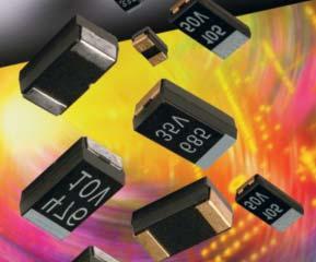
10 TAZ Series CWR09 - MIL-PRF-55365/4 Established Reliability, COTS-Plus & Space Level MARKING (White marking on black body) Polarity Stripe (+) Rated Voltage This is the original high reliability molded tantalum chip series and the case sizes still represent the most flexible of surface mount form factors. TAZ offers nine case sizes, eight of which (A through H) are fully qualified to MIL- PRF-55365/4, and also includes the original sub-miniature R case (non-qpl). This series is fully interchangeable with CWR06 conformal types, while offering the advantages of molded body/compliant termination construction (ensuring no TCE mismatch with any substrate). This construction is compatible with a wide range of SMT board assembly processes including wave or reflow solder, conductive epoxy or compression bonding techniques. The parts also carry full polarity and capacitance / voltage marking. The five smaller cases are characterized by their low profile construction, with the A case being the world s smallest molded military tantalum chip. CASE DIMENSIONS: Case Length (L) Width (W) Height (H) ±0.38 (0.015) ±0.38 (0.015) ±0.38 (0.015) A 2.54 (0.100) 1.27 (0.050) 1.27 (0.050) B 3.81 (0.150) 1.27 (0.050) 1.27 (0.050) C 5.08 (0.200) 1.27 (0.050) 1.27 (0.050) D 3.81 (0.150) 2.54 (0.100) 1.27 (0.050) E 5.08 (0.200) 2.54 (0.100) 1.27 (0.050) F 5.59 (0.220) 3.43 (0.135) 1.78 (0.070) G 6.73 (0.265) 2.79 (0.110) 2.79 (0.110) H 7.24 (0.285) 3.81 (0.150) 2.79 (0.110) R All 4V to 50V ratings are qualified to MIL-PRF Weibull B, C, D and T levels, with all surge options ( A, B & C ) available. For Space Level applications, AVX SRC 9000 qualification is recommended (see ratings table for part number availability). There are four termination finishes available: solder plated, fused solder plated, hot solder dipped and gold plated (these are H, K, C and B termination, respectively, per MIL-PRF ). In addition, the molding compound has been selected to meet the requirements of UL94V-0 (Flame Retardancy) and outgassing requirements of ASTM E-595. For moisture sensitivity levels please refer to the High Reliability Tantalum MSL section located in the back of the High Reliability Tantalum Catalog. millimeters (inches) Term. Length (A) Term. Width (W 1 ) +0.25/-0.13 S min (+0.010/-0.005) 1.27± (0.050±0.005) 0.76 (0.030) (0.015) 1.27± (0.050±0.005) 0.76 (0.030) (0.065) 1.27± (0.050±0.005) 0.76 (0.030) (0.115) / ( /-0.010) 0.76 (0.030) (0.065) / ( /-0.010) 0.76 (0.030) (0.115) 3.30± (0.130±0.005) 0.76 (0.030) (0.135) 2.67± (0.105±0.005) 1.27 (0.050) (0.140) / (0.050) 4.06 ( /-0.020) (0.160) 1.30 (0.051) 0.50 (0.020) 2.05 (0.081) (0.008) 1.20 (0.047) 1.0± (0.012) ±0.20 (0.008) (0.004) max (0.039±0.004) (0.008) Typical Weight (g) CWR09 MIL-PRF-55365/4 CAPACITANCE AND RATED VOLTAGE, V R (VOLTAGE CODE) RANGE (LETTER DENOTES CASE SIZE) Rated Voltage DC (VR) at 85ºC μf 4V (C) 6V (D) 10V (F) 15V (H) 20V (J) 25V (K) 35V (M) 50V (N) A A A B R R A B R A B C A B B C D A/R B C D E A B C D E F A/R B C D E F B C D E F G B C D E F G H C D E F G H D E F G E F G H F G H F G H G H G H H 0.71 (0.028)
11 TAZ Series CWR09 - MIL-PRF-55365/4 Established Reliability, COTS-Plus & Space Level HOW TO ORDER COTS-PLUS & MIL QPL (CWR09): TAZ H 686 * 006 C 0 ^ ++ Type Case Size pf code: 1st two digits represent significant figures 3rd digit represents multiplier (number of zeros to follow) Tolerance M = ±20% K = ±10% J = ±5% Voltage 004 = 4Vdc 006 = 6Vdc 010 = 10Vdc 015 = 15Vdc 020 = 20Vdc 025 = 25Vdc 035 = 35Vdc 050 = 50Vdc Standard or Low ESR Range C = Std ESR L = Low ESR Packaging B = Bulk R = 7" T&R S = 13" T&R W = Waffle See page 8 for additional packaging options. Inspection Level S = Std. Conformance L = Group A M = MIL (JAN) CWR09 Reliability Grade Weibull: B = 0.1%/1000 hrs. 90% conf. C = 0.01%/1000 hrs. 90% conf. D = 0.001%/1000 hrs. 90% conf. Z = Non-ER Qualification Level 0 = N/A T = T Level 9 = SRC9000 Termination Finish H = Solder Plated 0 = Fused Solder Plated 8 = Hot Solder Dipped 9 = Gold Plated 7 = Matte Sn (COTS-Plus only) Surge Test Option 00 = None 23 = 10 Cycles, +25ºC 24 = 10 Cycles, -55ºC & +85ºC 45 = 10 cycles, -55ºC & +85ºC before Weibull LEAD-FREE COMPATIBLE COMPONENT CWR09 P/N CROSS REFERENCE: For RoHS compliant products, please select correct termination style. CWR09 D ^ Type Voltage C = 4Vdc D = 6Vdc F = 10Vdc H = 15Vdc J = 20Vdc K = 25Vdc M = 35Vdc N = 50Vdc Termination Finish H = Solder Plated K = Solder Fused C = Hot Solder Dipped B = Gold Plated pf code: 1st two digits represent significant figures 3rd digit represents multiplier (number of zeros to follow) Tolerance M = ±20% K = ±10% J = ±5% Reliability Grade Weibull: B = 0.1%/1000 hrs. 90% conf. C = 0.01%/1000 hrs. 90% conf. D = 0.001%/1000 hrs. 90% conf. T = T Level A = Non-ER Surge Test Option A = 10 cycles, +25 C B = 10 cycles, -55 C & +85 C C = 10 cycles, -55 C & +85 C before Weibull If blank, None required Packaging Bulk = Standard \TR = 7" T&R \TR13 = 13" T&R \W = Waffle See page 8 for additional packaging options. LEAD-FREE COMPATIBLE COMPONENT For RoHS compliant products, please select correct termination style. SPACE LEVEL OPTIONS TO SRC9000*: TAZ H 686 * 006 C 9 ^ ++ Type Case Size pf code: 1st two digits represent significant figures 3rd digit represents multiplier (number of zeros to follow) Tolerance M = ±20% K = ±10% J = ±5% Voltage 004 = 4Vdc 006 = 6Vdc 010 = 10Vdc 015 = 15Vdc 020 = 20Vdc 025 = 25Vdc 035 = 35Vdc 050 = 50Vdc Standard or Low ESR Range C = Std ESR L = Low ESR Packaging B = Bulk R = 7" T&R S = 13" T&R W = Waffle See page 8 for additional packaging options. Inspection Level L = Group A Reliability Grade Weibull: B = 0.1%/1000 hrs. 90% conf. C = 0.01%/1000 hrs. 90% conf. D = 0.001%/1000 hrs. 90% conf. Qualification Level 9 = SRC9000 Termination Finish H = Solder Plated 0 = Fused Solder Plated 8 = Hot Solder Dipped 9 = Gold Plated LEAD-FREE COMPATIBLE COMPONENT Surge Test Option 45 = 10 cycles, -55ºC & +85ºC before Weibull *Contact factory for AVX SRC9000 Space Level SCD details. TECHNICAL SPECIFICATIONS For RoHS compliant products, please select correct termination style. Technical Data: Unless otherwise specified, all technical data relate to an ambient temperature of 25 C Range: 0.10 μf to 100 μf Tolerance: ±5%; ±10%; ±20% Rated Voltage (V R ) 85 C: Category Voltage (V C ) 125 C: Surge Voltage (V S ) 85 C: Surge Voltage (V S ) 125 C: Temperature Range: -55 C to +125 C
12 TAZ Series CWR09 - MIL-PRF-55365/4 Established Reliability, COTS-Plus & Space Level Parametric Specifications by Rating per MIL-PRF-55365/4 Typical RMS Ripple Data by Rating RATING & PART NUMBER REFERENCE Cap DC Rated ESR DCL max DF Max Power 25ºC 85ºC 125ºC 25ºC 85ºC 120Hz 100kHz +25ºC +85ºC +125ºC +25ºC +(85/125)ºC -55ºC Dissipation Ripple Ripple Ripple Ripple Ripple Ripple CWR09 P/N AVX MIL & COTS-Plus P/N AVX SRC9000 P/N Case μf V Ohms A A A V V V (μa) (μa) (μa) (%) (%) (%) +25ºC (100kHz) (100kHz) (100kHz) (100kHz) (100kHz) (100kHz) TAZ R 334 * 004 C 0 ^ ++ R TAZ R 225 * 004 C 0 ^ ++ R CWR09C^225*@+ TAZ A 225 * 004 C 0 ^ ++ TAZ A 225 * 004 C 9 ^ ++ A CWR09C^475*@+ TAZ B 475 * 004 C 0 ^ ++ TAZ B 475 * 004 C 9 ^ ++ B CWR09C^685*@+ TAZ C 685 * 004 C 0 ^ ++ TAZ C 685 * 004 C 9 ^ ++ C CWR09C^106*@+ TAZ D 106 * 004 C 0 ^ ++ TAZ D 106 * 004 C 9 ^ ++ D CWR09C^156*@+ TAZ E 156 * 004 C 0 ^ ++ TAZ E 156 * 004 C 9 ^ ++ E CWR09C^336*@+ TAZ F 336 * 004 C 0 ^ ++ TAZ F 336 * 004 C 9 ^ ++ F CWR09C^686*@+ TAZ G 686 * 004 C 0 ^ ++ TAZ G 686 * 004 C 9 ^ ++ G CWR09C^107*@+ TAZ H 107 * 004 C 0 ^ ++ TAZ H 107 * 004 C 9 ^ ++ H CWR09D^155*@+ TAZ A 155 * 006 C 0 ^ ++ TAZ A 155 * 006 C 9 ^ ++ A CWR09D^335*@+ TAZ B 335 * 006 C 0 ^ ++ TAZ B 335 * 006 C 9 ^ ++ B CWR09D^475*@+ TAZ C 475 * 006 C 0 ^ ++ TAZ C 475 * 006 C 9 ^ ++ C CWR09D^685*@+ TAZ D 685 * 006 C 0 ^ ++ TAZ D 685 * 006 C 9 ^ ++ D CWR09D^106*@+ TAZ E 106 * 006 C 0 ^ ++ TAZ E 106 * 006 C 9 ^ ++ E CWR09D^226*@+ TAZ F 226 * 006 C 0 ^ ++ TAZ F 226 * 006 C 9 ^ ++ F CWR09D^476*@+ TAZ G 476 * 006 C 0 ^ ++ TAZ G 476 * 006 C 9 ^ ++ G CWR09D^686*@+ TAZ H 686 * 006 C 0 ^ ++ TAZ H 686 * 006 C 9 ^ ++ H TAZ R 334 * 010 C 0 ^ ++ R TAZ R 474 * 010 C 0 ^ ++ R TAZ R 105 * 010 C 0 ^ ++ R CWR09F^105*@+ TAZ A 105 * 010 C 0 ^ ++ TAZ A 105 * 010 C 9 ^ ++ A CWR09F^225*@+ TAZ B 225 * 010 C 0 ^ ++ TAZ B 225 * 010 C 9 ^ ++ B CWR09F^335*@+ TAZ C 335 * 010 C 0 ^ ++ TAZ C 335 * 010 C 9 ^ ++ C CWR09F^475*@+ TAZ D 475 * 010 C 0 ^ ++ TAZ D 475 * 010 C 9 ^ ++ D CWR09F^685*@+ TAZ E 685 * 010 C 0 ^ ++ TAZ E 685 * 010 C 9 ^ ++ E CWR09F^156*@+ TAZ F 156 * 010 C 0 ^ ++ TAZ F 156 * 010 C 9 ^ ++ F CWR09F^336*@+ TAZ G 336 * 010 C 0 ^ ++ TAZ G 336 * 010 C 9 ^ ++ G CWR09F^476*@+ TAZ H 476 * 010 C 0 ^ ++ TAZ H 476 * 010 C 9 ^ ++ H CWR09H^684*@+ TAZ A 684 * 015 C 0 ^ ++ TAZ A 684 * 015 C 9 ^ ++ A CWR09H^155*@+ TAZ B 155 * 015 C 0 ^ ++ TAZ B 155 * 015 C 9 ^ ++ B CWR09H^225*@+ TAZ C 225 * 015 C 0 ^ ++ TAZ C 225 * 015 C 9 ^ ++ C CWR09H^335*@+ TAZ D 335 * 015 C 0 ^ ++ TAZ D 335 * 015 C 9 ^ ++ D CWR09H^475*@+ TAZ E 475 * 015 C 0 ^ ++ TAZ E 475 * 015 C 9 ^ ++ E CWR09H^106*@+ TAZ F 106 * 015 C 0 ^ ++ TAZ F 106 * 015 C 9 ^ ++ F CWR09H^226*@+ TAZ G 226 * 015 C 0 ^ ++ TAZ G 226 * 015 C 9 ^ ++ G CWR09H^336*@+ TAZ H 336 * 015 C 0 ^ ++ TAZ H 336 * 015 C 9 ^ ++ H CWR09J^474*@+ TAZ A 474 * 020 C 0 ^ ++ TAZ A 474 * 020 C 9 ^ ++ A CWR09J^684*@+ TAZ B 684 * 020 C 0 ^ ++ TAZ B 684 * 020 C 9 ^ ++ B CWR09J^105*@+ TAZ B 105 * 020 C 0 ^ ++ TAZ B 105 * 020 C 9 ^ ++ B CWR09J^155*@+ TAZ C 155 * 020 C 0 ^ ++ TAZ C 155 * 020 C 9 ^ ++ C CWR09J^225*@+ TAZ D 225 * 020 C 0 ^ ++ TAZ D 225 * 020 C 9 ^ ++ D CWR09J^335*@+ TAZ E 335 * 020 C 0 ^ ++ TAZ E 335 * 020 C 9 ^ ++ E CWR09J^685*@+ TAZ F 685 * 020 C 0 ^ ++ TAZ F 685 * 020 C 9 ^ ++ F CWR09J^156*@+ TAZ G 156 * 020 C 0 ^ ++ TAZ G 156 * 020 C 9 ^ ++ G CWR09J^226*@+ TAZ H 226 * 020 C 0 ^ ++ TAZ H 226 * 020 C 9 ^ ++ H CWR09K^334*@+ TAZ A 334 * 025 C 0 ^ ++ TAZ A 334 * 025 C 9 ^ ++ A CWR09K^684*@+ TAZ B 684 * 025 C 0 ^ ++ TAZ B 684 * 025 C 9 ^ ++ B CWR09K^105*@+ TAZ C 105 * 025 C 0 ^ ++ TAZ C 105 * 025 C 9 ^ ++ C CWR09K^155*@+ TAZ D 155 * 025 C 0 ^ ++ TAZ D 155 * 025 C 9 ^ ++ D CWR09K^225*@+ TAZ E 225 * 025 C 0 ^ ++ TAZ E 225 * 025 C 9 ^ ++ E CWR09K^475*@+ TAZ F 475 * 025 C 0 ^ ++ TAZ F 475 * 025 C 9 ^ ++ F CWR09K^685*@+ TAZ G 685 * 025 C 0 ^ ++ TAZ G 685 * 025 C 9 ^ ++ G CWR09K^106*@+ TAZ G 106 * 025 C 0 ^ ++ TAZ G 106 * 025 C 9 ^ ++ G CWR09K^156*@+ TAZ H 156 * 025 C 0 ^ ++ TAZ H 156 * 025 C 9 ^ ++ H All technical data relates to an ambient temperature of +25 C. and DF are measured at 120Hz, 0.5V RMS with a maximum DC bias of 2.2 volts. DCL is measured at rated voltage after 5 minutes. NOTE: AVX reserves the right to supply a higher voltage rating or tighter tolerance part in the same case size, to the same reliability standards
13 TAZ Series CWR09 - MIL-PRF-55365/4 Established Reliability, COTS-Plus & Space Level Parametric Specifications by Rating per MIL-PRF-55365/4 Typical RMS Ripple Data by Rating RATING & PART NUMBER REFERENCE Cap DC Rated ESR DCL max DF Max Power 25ºC 85ºC 125ºC 25ºC 85ºC 120Hz 100kHz +25ºC +85ºC +125ºC +25ºC +(85/125)ºC -55ºC Dissipation Ripple Ripple Ripple Ripple Ripple Ripple CWR09 P/N AVX MIL & COTS-Plus p/n AVX SRC9000 P/N Case μf V Ohms A A A V V V (μa) (μa) (μa) (%) (%) (%) +25ºC (100kHz) (100kHz) (100kHz) (100kHz) (100kHz) (100kHz) CWR09M^224*@+ TAZ A 224 * 035 C 0 ^ ++ TAZ A 224 * 035 C 9 ^ ++ A CWR09M^474*@+ TAZ B 474 * 035 C 0 ^ ++ TAZ B 474 * 035 C 9 ^ ++ B CWR09M^684*@+ TAZ C 684 * 035 C 0 ^ ++ TAZ C 684 * 035 C 9 ^ ++ C CWR09M^105*@+ TAZ D 105 * 035 C 0 ^ ++ TAZ D 105 * 035 C 9 ^ ++ D CWR09M^155*@+ TAZ E 155 * 035 C 0 ^ ++ TAZ E 155 * 035 C 9 ^ ++ E CWR09M^335*@+ TAZ F 335 * 035 C 0 ^ ++ TAZ F 335 * 035 C 9 ^ ++ F CWR09M^475*@+ TAZ G 475 * 035 C 0 ^ ++ TAZ G 475 * 035 C 9 ^ ++ G CWR09M^685*@+ TAZ H 685 * 035 C 0 ^ ++ TAZ H 685 * 035 C 9 ^ ++ H CWR09N^104*@+ TAZ A 104 * 050 C 0 ^ ++ TAZ A 104 * 050 C 9 ^ ++ A CWR09N^154*@+ TAZ A 154 * 050 C 0 ^ ++ TAZ A 154 * 050 C 9 ^ ++ A CWR09N^224*@+ TAZ B 224 * 050 C 0 ^ ++ TAZ B 224 * 050 C 9 ^ ++ B CWR09N^334*@+ TAZ B 334 * 050 C 0 ^ ++ TAZ B 334 * 050 C 9 ^ ++ B CWR09N^474*@+ TAZ C 474 * 050 C 0 ^ ++ TAZ C 474 * 050 C 9 ^ ++ C CWR09N^684*@+ TAZ D 684 * 050 C 0 ^ ++ TAZ D 684 * 050 C 9 ^ ++ D CWR09N^105*@+ TAZ E 105 * 050 C 0 ^ ++ TAZ E 105 * 050 C 9 ^ ++ E CWR09N^155*@+ TAZ F 155 * 050 C 0 ^ ++ TAZ F 155 * 050 C 9 ^ ++ F CWR09N^225*@+ TAZ F 225 * 050 C 0 ^ ++ TAZ F 225 * 050 C 9 ^ ++ F CWR09N^335*@+ TAZ G 335 * 050 C 0 ^ ++ TAZ G 335 * 050 C 9 ^ ++ G CWR09N^475*@+ TAZ H 475 * 050 C 0 ^ ++ TAZ H 475 * 050 C 9 ^ ++ H All technical data relates to an ambient temperature of +25 C. and DF are measured at 120Hz, 0.5V RMS with a maximum DC bias of 2.2 volts. DCL is measured at rated voltage after 5 minutes. NOTE: AVX reserves the right to supply a higher voltage rating or tighter tolerance part in the same case size, to the same reliability standards
14 TAZ Series CWR19 - MIL-PRF-55365/11 Established Reliability, COTS-Plus & Space Level An extended range of capacitor ratings beyond CWR09 that is fully qualified to MIL-PRF /11, this series represents the most flexible of surface mount form factors, offering nine case sizes (the original A through H of CWR09) and adds the new X case size. The molded body / compliant termination construction ensures no TCE mismatch with any substrate. This construction is compatible with a wide range of SMT board assembly processes including wave or reflow solder, conductive epoxy or compression bonding techniques. The parts also carry full polarity and capacitance / voltage marking. The four smaller cases are characterized by their low profile construction, with the A case being the world s smallest molded military tantalum chip. The series is qualified to MIL-PRF Weibull B, C, D and T levels, with all surge options ( A, B & C ) available. For Space Level applications, AVX SRC 9000 qualification is recommended (see ratings table for part number availability). There are four termination finishes available: solder plated, fused solder plated, hot solder dipped and gold plated (these are H, K, C and B termination, respectively, per MIL-PRF ). In addition, the molding compound has been selected to meet the requirements of UL94V-0 (Flame Retardancy) and outgassing requirements of ASTM E-595. For moisture sensitivity levels please refer to the High Reliability Tantalum MSL section located in the back of the High Reliability Tantalum Catalog. MARKING (White marking on black body) Polarity Stripe (+) Rated Voltage CASE DIMENSIONS: millimeters (inches) Term. Length (A) Case Length (L) Width (W) Height (H) Typical Term. Width (W 1 ) +0.25/-0.13 S min ±0.38 (0.015) ±0.38 (0.015) ±0.38 (0.015) Weight (g) (+0.010/-0.005) A 2.54 (0.100) 1.27 (0.050) 1.27 (0.050) 1.27±0.13 (0.050±0.005) 0.76 (0.030) 0.38 (0.015) B 3.81 (0.150) 1.27 (0.050) 1.27 (0.050) 1.27±0.13 (0.050±0.005) 0.76 (0.030) 1.65 (0.065) C 5.08 (0.200) 1.27 (0.050) 1.27 (0.050) 1.27±0.13 (0.050±0.005) 0.76 (0.030) 2.92 (0.115) /-0.25 D 3.81 (0.150) 2.54 (0.100) 1.27 (0.050) ( /-0.010) 0.76 (0.030) 1.65 (0.065) /-0.25 E 5.08 (0.200) 2.54 (0.100) 1.27 (0.050) ( /-0.010) 0.76 (0.030) 2.92 (0.115) F 5.59 (0.220) 3.43 (0.135) 1.78 (0.070) G 6.73 (0.265) 2.79 (0.110) 2.79 (0.110) H 7.24 (0.285) 3.81 (0.150) 2.79 (0.110) X 6.93 (0.273) 5.41 (0.213) 2.74 (0.108) 3.30±0.13 (0.130±0.005) 0.76 (0.030) 3.43 (0.135) ±0.13 (0.105±0.005) 1.27 (0.050) 3.56 (0.140) /-0.51 ( /-0.020) 3.05±0.13 (0.120±0.005) 1.27 (0.050) 4.06 (0.160) (0.047) N/A CWR19-MIL-PRF 55365/11 CAPACITANCE AND RATED VOLTAGE, V R (VOLTAGE CODE) RANGE (LETTER DENOTES CASE SIZE) Rated voltage DC (V R ) at 85ºC μf 4V (C) 6V (D) 10V (F) 15V (H) 20V (J) 25V (K) 35V (M) A A A A A B A B A A B D A A A B D E A A B/C B/C/D E A B B/C/D D/E E F G B B B/C/D/E D/E E/F H B B/D/E D/E E/F F G X B/D D/E E F G G/H D/E E F F/G H H E F F/G G/H H/X E F/G G G/H F G G/H H G G H/X H H H H H
15 TAZ Series CWR19 - MIL-PRF-55365/11 Established Reliability, COTS-Plus & Space Level HOW TO ORDER COTS-PLUS & MIL QPL (CWR19): TAZ H 227 * 006 C 0 ^ ++ Type Case Size pf code: 1st two digits represent significant figures 3rd digit represents multiplier (number of zeros to follow) Tolerance M = ±20% K = ±10% J = ±5% Voltage 004 = 4Vdc 006 = 6Vdc 010 = 10Vdc 015 = 15Vdc 020 = 20Vdc 025 = 25Vdc 035 = 35Vdc Standard or Low ESR Range C = Std ESR L = Low ESR Packaging B = Bulk R = 7" T&R S = 13" T&R W = Waffle See page 8 for additional packaging options. Inspection Level S = Std. Conformance L = Group A M = MIL (JAN) CWR19 Reliability Grade Weibull: B = 0.1%/1000 hrs. 90% conf. C = 0.01%/1000 hrs. 90% conf. D = 0.001%/1000 hrs. 90% conf. Z = Non-ER Qualification Level 0 = N/A T = T Level 9 = SRC9000 Termination Finish H = Solder Plated 0 = Fused Solder Plated 8 = Hot Solder Dipped 9 = Gold Plated 7 = Matte Sn (COTS-Plus only) Surge Test Option 00 = None 23 = 10 Cycles, +25ºC 24 = 10 Cycles, -55ºC & +85ºC 45 = 10 cycles, -55ºC & +85ºC before Weibull LEAD-FREE COMPATIBLE COMPONENT CWR19 P/N CROSS REFERENCE: For RoHS compliant products, please select correct termination style. CWR19 D ^ 227 H + Type Voltage C = 4Vdc D = 6Vdc F = 10Vdc H = 15Vdc J = 20Vdc K = 25Vdc M = 35Vdc Termination Finish H = Solder Plated K = Solder Fused C = Hot Solder Dipped B = Gold Plated LEAD-FREE COMPATIBLE COMPONENT pf code: 1st two digits represent significant figures 3rd digit represents multiplier (number of zeros to follow) Tolerance M = ±20% K = ±10% J = ±5% Reliability Grade Weibull: B = 0.1%/1000 hrs. 90% conf. C = 0.01%/1000 hrs. 90% conf. D = 0.001%/1000 hrs. 90% conf. T = T Level A = Non-ER Case Size Surge Test Option A = 10 cycles, +25 C B = 10 cycles, -55 C & +85 C C = 10 cycles, -55 C & +85 C before Weibull Z = None required Packaging Bulk = Standard \TR = 7" T&R \TR13 = 13" T&R \W = Waffle See page 8 for additional packaging options. For RoHS compliant products, please select correct termination style. SPACE LEVEL OPTIONS TO SRC9000*: TAZ H 227 * 006 C 9 ^ ++ Type Case Size pf code: 1st two digits represent significant figures 3rd digit represents multiplier (number of zeros to follow) Tolerance M = ±20% K = ±10% J = ±5% Voltage 004 = 4Vdc 006 = 6Vdc 010 = 10Vdc 015 = 15Vdc 020 = 20Vdc 025 = 25Vdc 035 = 35Vdc Standard or Low ESR Range C = Std ESR L = Low ESR Packaging B = Bulk R = 7" T&R S = 13" T&R W = Waffle See page 8 for additional packaging options. Inspection Level L = Group A Reliability Grade Weibull: B = 0.1%/1000 hrs. 90% conf. C = 0.01%/1000 hrs. 90% conf. D = 0.001%/1000 hrs. 90% conf. Qualification Level 9 = SRC9000 Termination Finish H = Solder Plated 0 = Fused Solder Plated 8 = Hot Solder Dipped 9 = Gold Plated Surge Test Option 45 = 10 cycles, -55ºC & +85ºC before Weibull *Contact factory for AVX SRC9000 Space Level SCD details. TECHNICAL SPECIFICATIONS LEAD-FREE COMPATIBLE COMPONENT For RoHS compliant products, please select correct termination style. Technical Data: Unless otherwise specified, all technical data relate to an ambient temperature of 25 C Range: 0.33 μf to 330 μf Tolerance: ±5%; ±10%; ±20% Rated Voltage (V R ) 85 C: Category Voltage (V C ) 125 C: Surge Voltage (V S ) 85 C: Surge Voltage (V S ) 125 C: Temperature Range: -55 C to +125 C
16 TAZ Series CWR19 - MIL-PRF-55365/11 Established Reliability, COTS-Plus & Space Level Parametric Specifications by Rating per MIL-PRF-55365/11 Typical RMS Ripple Data by Rating RATING & PART NUMBER REFERENCE Cap DC Rated ESR DCL max DF Max Power 25ºC 85ºC 125ºC 25ºC 85ºC 120Hz 100kHz +25ºC +85ºC +125ºC +25ºC +(85/125)ºC -55ºC Dissipation Ripple Ripple Ripple Ripple Ripple Ripple CWR19 P/N AVX MIL & COTS-Plus P/N AVX SRC9000 P/N Case μf V Ohms A A A V V V (μa) (μa) (μa) (%) (%) (%) +25ºC (100kHz) (100kHz) (100kHz) (100kHz) (100kHz) (100kHz) CWR19C^335*@A+ TAZ A 335 * 004 C 0 ^ ++ TAZ A 335 * 004 C 9 ^ ++ A CWR19C^475*@A+ TAZ A 475 * 004 C 0 ^ ++ TAZ A 475 * 004 C 9 ^ ++ A CWR19C^685*@A+ TAZ A 685 * 004 C 0 ^ ++ TAZ A 685 * 004 C 9 ^ ++ A CWR19C^106*@B+ TAZ B 106 * 004 C 0 ^ ++ TAZ B 106 * 004 C 9 ^ ++ B CWR19C^156*@B+ TAZ B 156 * 004 C 0 ^ ++ TAZ B 156 * 004 C 9 ^ ++ B CWR19C^226*@B+ TAZ B 226 * 004 C 0 ^ ++ TAZ B 226 * 004 C 9 ^ ++ B CWR19C^226*@D+ TAZ D 226 * 004 C 0 ^ ++ TAZ D 226 * 004 C 9 ^ ++ D CWR19C^336*@D+ TAZ D 336 * 004 C 0 ^ ++ TAZ D 336 * 004 C 9 ^ ++ D CWR19C^336*@E+ TAZ E 336 * 004 C 0 ^ ++ TAZ E 336 * 004 C 9 ^ ++ E CWR19C^476*@E+ TAZ E 476 * 004 C 0 ^ ++ TAZ E 476 * 004 C 9 ^ ++ E CWR19C^686*@E+ TAZ E 686 * 004 C 0 ^ ++ TAZ E 686 * 004 C 9 ^ ++ E CWR19C^107*@F+ TAZ F 107 * 004 C 0 ^ ++ TAZ F 107 * 004 C 9 ^ ++ F CWR19C^157*@G+ TAZ G 157 * 004 C 0 ^ ++ TAZ G 157 * 004 C 9 ^ ++ G CWR19C^227*@H+ TAZ H 227 * 004 C 0 ^ ++ TAZ H 227 * 004 C 9 ^ ++ H CWR19C^337*@H+ TAZ H 337 * 004 C 0 ^ ++ TAZ H 337 * 004 C 9 ^ ++ H CWR19D^335*@A+ TAZ A 335 * 006 C 0 ^ ++ TAZ A 335 * 006 C 9 ^ ++ A CWR19D^475*@A+ TAZ A 475 * 006 C 0 ^ ++ TAZ A 475 * 006 C 9 ^ ++ A CWR19D^685*@B+ TAZ B 685 * 006 C 0 ^ ++ TAZ B 685 * 006 C 9 ^ ++ B CWR19D^106*@B+ TAZ B 106 * 006 C 0 ^ ++ TAZ B 106 * 006 C 9 ^ ++ B CWR19D^156*@B+ TAZ B 156 * 006 C 0 ^ ++ TAZ B 156 * 006 C 9 ^ ++ B CWR19D^156*@D+ TAZ D 156 * 006 C 0 ^ ++ TAZ D 156 * 006 C 9 ^ ++ D CWR19D^226*@D+ TAZ D 226 * 006 C 0 ^ ++ TAZ D 226 * 006 C 9 ^ ++ D CWR19D^156*@E+ TAZ E 156 * 006 C 0 ^ ++ TAZ E 156 * 006 C 9 ^ ++ E CWR19D^226*@E+ TAZ E 226 * 006 C 0 ^ ++ TAZ E 226 * 006 C 9 ^ ++ E CWR19D^336*@E+ TAZ E 336 * 006 C 0 ^ ++ TAZ E 336 * 006 C 9 ^ ++ E CWR19D^476*@F+ TAZ F 476 * 006 C 0 ^ ++ TAZ F 476 * 006 C 9 ^ ++ F CWR19D^686*@F+ TAZ F 686 * 006 C 0 ^ ++ TAZ F 686 * 006 C 9 ^ ++ F CWR19D^686*@G+ TAZ G 686 * 006 C 0 ^ ++ TAZ G 686 * 006 C 9 ^ ++ G CWR19D^107*@G+ TAZ G 107 * 006 C 0 ^ ++ TAZ G 107 * 006 C 9 ^ ++ G CWR19D^157*@G+ TAZ G 157 * 006 C 0 ^ ++ TAZ G 157 * 006 C 9 ^ ++ G CWR19D^227*@H+ TAZ H 227 * 006 C 0 ^ ++ TAZ H 227 * 006 C 9 ^ ++ H CWR19D^337*@H+ TAZ H 337 * 006 C 0 ^ ++ TAZ H 337 * 006 C 9 ^ ++ H CWR19F^225*@A+ TAZ A 225 * 010 C 0 ^ ++ TAZ A 225 * 010 C 9 ^ ++ A CWR19F^335*@A+ TAZ A 335 * 010 C 0 ^ ++ TAZ A 335 * 010 C 9 ^ ++ A CWR19F^475*@B+ TAZ B 475 * 010 C 0 ^ ++ TAZ B 475 * 010 C 9 ^ ++ B CWR19F^685*@B+ TAZ B 685 * 010 C 0 ^ ++ TAZ B 685 * 010 C 9 ^ ++ B CWR19F^106*@B+ TAZ B 106 * 010 C 0 ^ ++ TAZ B 106 * 010 C 9 ^ ++ B CWR19F^475*@C+ TAZ C 475 * 010 C 0 ^ ++ TAZ C 475 * 010 C 9 ^ ++ C CWR19F^685*@C+ TAZ C 685 * 010 C 0 ^ ++ TAZ C 685 * 010 C 9 ^ ++ C CWR19F^106*@C+ TAZ C 106 * 010 C 0 ^ ++ TAZ C 106 * 010 C 9 ^ ++ C CWR19F^685*@D+ TAZ D 685 * 010 C 0 ^ ++ TAZ D 685 * 010 C 9 ^ ++ D CWR19F^106*@D+ TAZ D 106 * 010 C 0 ^ ++ TAZ D 106 * 010 C 9 ^ ++ D CWR19F^156*@D+ TAZ D 156 * 010 C 0 ^ ++ TAZ D 156 * 010 C 9 ^ ++ D CWR19F^106*@E+ TAZ E 106 * 010 C 0 ^ ++ TAZ E 106 * 010 C 9 ^ ++ E CWR19F^156*@E+ TAZ E 156 * 010 C 0 ^ ++ TAZ E 156 * 010 C 9 ^ ++ E CWR19F^226*@E+ TAZ E 226 * 010 C 0 ^ ++ TAZ E 226 * 010 C 9 ^ ++ E CWR19F^336*@F+ TAZ F 336 * 010 C 0 ^ ++ TAZ F 336 * 010 C 9 ^ ++ F CWR19F^476*@F+ TAZ F 476 * 010 C 0 ^ ++ TAZ F 476 * 010 C 9 ^ ++ F CWR19F^476*@G+ TAZ G 476 * 010 C 0 ^ ++ TAZ G 476 * 010 C 9 ^ ++ G CWR19F^686*@G+ TAZ G 686 * 010 C 0 ^ ++ TAZ G 686 * 010 C 9 ^ ++ G CWR19F^107*@G+ TAZ G 107 * 010 C 0 ^ ++ TAZ G 107 * 010 C 9 ^ ++ G CWR19F^107*@H+ TAZ H 107 * 010 C 0 ^ ++ TAZ H 107 * 010 C 9 ^ ++ H CWR19F^157*@H+ TAZ H 157 * 010 C 0 ^ ++ TAZ H 157 * 010 C 9 ^ ++ H CWR19F^227*@H+ TAZ H 227 * 010 C 0 ^ ++ TAZ H 227 * 010 C 9 ^ ++ H CWR19F^157*@X+ TAZ X 157 * 010 C 0 ^ ++ TAZ X 157 * 010 C 9 ^ ++ X All technical data relates to an ambient temperature of +25 C. and DF are measured at 120Hz, 0.5V RMS with a maximum DC bias of 2.2 volts. DCL is measured at rated voltage after 5 minutes. NOTE: AVX reserves the right to supply a higher voltage rating or tighter tolerance part in the same case size, to the same reliability standards
17 TAZ Series CWR19 - MIL-PRF-55365/11 Established Reliability, COTS-Plus & Space Level Parametric Specifications by Rating per MIL-PRF-55365/11 Typical RMS Ripple Data by Rating RATING & PART NUMBER REFERENCE Cap DC Rated ESR DCL max DF Max Power 25ºC 85ºC 125ºC 25ºC 85ºC 120Hz 100kHz +25ºC +85ºC +125ºC +25ºC +(85/125)ºC -55ºC Dissipation Ripple Ripple Ripple Ripple Ripple Ripple CWR19 P/N AVX MIL & COTS-Plus P/N AVX SRC9000 P/N Case μf V Ohms A A A V V V (μa) (μa) (μa) (%) (%) (%) +25ºC (100kHz) (100kHz) (100kHz) (100kHz) (100kHz) (100kHz) CWR19H^105*@A+ TAZ A 105 * 015 C 0 ^ ++ TAZ A 105 * 015 C 9 ^ ++ A CWR19H^155*@A+ TAZ A 155 * 015 C 0 ^ ++ TAZ A 155 * 015 C 9 ^ ++ A CWR19H^225*@A+ TAZ A 225 * 015 C 0 ^ ++ TAZ A 225 * 015 C 9 ^ ++ A CWR19H^335*@B+ TAZ B 335 * 015 C 0 ^ ++ TAZ B 335 * 015 C 9 ^ ++ B CWR19H^475*@B+ TAZ B 475 * 015 C 0 ^ ++ TAZ B 475 * 015 C 9 ^ ++ B CWR19H^475*@C+ TAZ C 475 * 015 C 0 ^ ++ TAZ C 475 * 015 C 9 ^ ++ C CWR19H^475*@D+ TAZ D 475 * 015 C 0 ^ ++ TAZ D 475 * 015 C 9 ^ ++ D CWR19H^685*@D+ TAZ D 685 * 015 C 0 ^ ++ TAZ D 685 * 015 C 9 ^ ++ D CWR19H^106*@D+ TAZ D 106 * 015 C 0 ^ ++ TAZ D 106 * 015 C 9 ^ ++ D CWR19H^685*@E+ TAZ E 685 * 015 C 0 ^ ++ TAZ E 685 * 015 C 9 ^ ++ E CWR19H^106*@E+ TAZ E 106 * 015 C 0 ^ ++ TAZ E 106 * 015 C 9 ^ ++ E CWR19H^156*@E+ TAZ E 156 * 015 C 0 ^ ++ TAZ E 156 * 015 C 9 ^ ++ E CWR19H^156*@F+ TAZ F 156 * 015 C 0 ^ ++ TAZ F 156 * 015 C 9 ^ ++ F CWR19H^226*@F+ TAZ F 226 * 015 C 0 ^ ++ TAZ F 226 * 015 C 9 ^ ++ F CWR19H^336*@F+ TAZ F 336 * 015 C 0 ^ ++ TAZ F 336 * 015 C 9 ^ ++ F CWR19H^336*@G+ TAZ G 336 * 015 C 0 ^ ++ TAZ G 336 * 015 C 9 ^ ++ G CWR19H^476*@G+ TAZ G 476 * 015 C 0 ^ ++ TAZ G 476 * 015 C 9 ^ ++ G CWR19H^686*@G+ TAZ G 686 * 015 C 0 ^ ++ TAZ G 686 * 015 C 9 ^ ++ G CWR19H^476*@H+ TAZ H 476 * 015 C 0 ^ ++ TAZ H 476 * 015 C 9 ^ ++ H CWR19H^686*@H+ TAZ H 686 * 015 C 0 ^ ++ TAZ H 686 * 015 C 9 ^ ++ H CWR19H^107*@H+ TAZ H 107 * 015 C 0 ^ ++ TAZ H 107 * 015 C 9 ^ ++ H CWR19J^684*@A+ TAZ A 684 * 020 C 0 ^ ++ TAZ A 684 * 020 C 9 ^ ++ A CWR19J^105*@A+ TAZ A 105 * 020 C 0 ^ ++ TAZ A 105 * 020 C 9 ^ ++ A CWR19J^155*@B+ TAZ B 155 * 020 C 0 ^++ TAZ B 155 * 020 C 9 ^++ B CWR19J^225*@B+ TAZ B 225 * 020 C 0 ^ ++ TAZ B 225 * 020 C 9 ^ ++ B CWR19J^335*@D+ TAZ D 335 * 020 C 0 ^ ++ TAZ D 335 * 020 C 9 ^ ++ D CWR19J^475*@E+ TAZ E 475 * 020 C 0 ^ ++ TAZ E 475 * 020 C 9 ^ ++ E CWR19J^685*@E+ TAZ E 685 * 020 C 0 ^ ++ TAZ E 685 * 020 C 9 ^ ++ E CWR19J^106*@E+ TAZ E 106 * 020 C 0 ^ ++ TAZ E 106 * 020 C 9 ^ ++ E CWR19J^106*@F+ TAZ F 106 * 020 C 0 ^ ++ TAZ F 106 * 020 C 9 ^ ++ F CWR19J^156*@F+ TAZ F 156 * 020 C 0 ^ ++ TAZ F 156 * 020 C 9 ^ ++ F CWR19J^226*@G+ TAZ G 226 * 020 C 0 ^ ++ TAZ G 226 * 020 C 9 ^ ++ G CWR19J^336*@H+ TAZ H 336 * 020 C 0 ^ ++ TAZ H 336 * 020 C 9 ^ ++ H CWR19J^476*@H+ TAZ H 476 * 020 C 0 ^ ++ TAZ H 476 * 020 C 9 ^ ++ H CWR19J^476*@X+ TAZ X 476 * 020 C 0 ^ ++ TAZ X 476 * 020 C 9 ^ ++ X CWR19K^474*@A+ TAZ A 474 * 025 C 0 ^ ++ TAZ A 474 * 025 C 9 ^ ++ A CWR19K^105*@B+ TAZ B 105 * 025 C 0 ^ ++ TAZ B 105 * 025 C 9 ^ ++ B CWR19K^225*@D+ TAZ D 225 * 025 C 0 ^ ++ TAZ D 225 * 025 C 9 ^ ++ D CWR19K^335*@E+ TAZ E 335 * 025 C 0 ^ ++ TAZ E 335 * 025 C 9 ^ ++ E CWR19K^685*@F+ TAZ F 685 * 025 C 0 ^ ++ TAZ F 685 * 025 C 9 ^ ++ F CWR19K^156*@G+ TAZ G 156 * 025 C 0 ^ ++ TAZ G 156 * 025 C 9 ^ ++ G CWR19K^226*@G+ TAZ G 226 * 025 C 0 ^ ++ TAZ G 226 * 025 C 9 ^ ++ G CWR19K^226*@H+ TAZ H 226 * 025 C 0 ^ ++ TAZ H 226 * 025 C 9 ^ ++ H CWR19K^336*@H+ TAZ H 336 * 025 C 0 ^ ++ TAZ H 336 * 025 C 9 ^ ++ H CWR19M^334*@A+ TAZ A 334 * 035 C 0 ^ ++ TAZ A 334 * 035 C 9 ^ ++ A CWR19M^685*@G+ TAZ G 685 * 035 C 0 ^ ++ TAZ G 685 * 035 C 9 ^ ++ G CWR19M^106*@H+ TAZ H 106 * 035 C 0 ^ ++ TAZ H 106 * 035 C 9 ^ ++ H CWR19M^156*@X+ TAZ X 156 * 035 C 0 ^ ++ TAZ X 156 * 035 C 9 ^ ++ X All technical data relates to an ambient temperature of +25 C. and DF are measured at 120Hz, 0.5V RMS with a maximum DC bias of 2.2 volts. DCL is measured at rated voltage after 5 minutes. NOTE: AVX reserves the right to supply a higher voltage rating or tighter tolerance part in the same case size, to the same reliability standards
18 TAZ Series CWR29 - MIL-PRF-55365/11 Established Reliability, COTS-Plus & Space Level MARKING (White marking on black body) Polarity Stripe (+) Rated Voltage A low ESR version of CWR09 and CWR19 that is fully qualified to MIL-PRF-55365/11, the CWR29 series represents the most flexible of surface mount form factors and the optimum power handing for all filtering applications. It is offered in nine case sizes (the original A through H of CWR09 and adding the new X case size). The molded body / compliant termination construction ensures no TCE mismatch with any substrate. This construction is compatible with a wide range of SMT board assembly processes including wave or reflow solder, conductive epoxy or compression bonding techniques. The parts also carry full polarity and capacitance / voltage marking. The five smaller cases are characterized by their low profile construction, with the A case being the world s smallest molded military tantalum chip. CASE DIMENSIONS: The series is qualified to MIL-PRF Weibull B, C, D and T levels, with all surge options ( A, B & C ) available. For Space Level applications, AVX SRC 9000 qualification is recommended (see ratings table for part number availability). There are four termination finishes available: solder plated, fused solder plated, hot solder dipped and gold plated (these are H, K, C and B termination, respectively, per MIL-PRF ). In addition, the molding compound has been selected to meet the requirements of UL94V-0 (Flame Retardancy) and outgassing requirements of ASTM E-595. For moisture sensitivity levels please refer to the High Reliability Tantalum MSL section located in the back of the High Reliability Tantalum Catalog. millimeters (inches) Term. Length (A) Case Length (L) Width (W) Height (H) Typical Term. Width (W 1 ) +0.25/-0.13 S min ±0.38 (0.015) ±0.38 (0.015) ±0.38 (0.015) Weight (g) (+0.010/-0.005) A 2.54 (0.100) 1.27 (0.050) 1.27 (0.050) 1.27±0.13 (0.050±0.005) 0.76 (0.030) 0.38 (0.015) B 3.81 (0.150) 1.27 (0.050) 1.27 (0.050) 1.27±0.13 (0.050±0.005) 0.76 (0.030) 1.65 (0.065) C 5.08 (0.200) 1.27 (0.050) 1.27 (0.050) 1.27±0.13 (0.050±0.005) 0.76 (0.030) 2.92 (0.115) /-0.25 D 3.81 (0.150) 2.54 (0.100) 1.27 (0.050) ( /-0.010) 0.76 (0.030) 1.65 (0.065) /-0.25 E 5.08 (0.200) 2.54 (0.100) 1.27 (0.050) ( /-0.010) 0.76 (0.030) 2.92 (0.115) F 5.59 (0.220) 3.43 (0.135) 1.78 (0.070) 3.30±0.13 (0.130±0.005) 0.76 (0.030) 3.43 (0.135) G 6.73 (0.265) 2.79 (0.110) 2.79 (0.110) 2.67±0.13 (0.105±0.005) 1.27 (0.050) 3.56 (0.140) H 7.24 (0.285) 3.81 (0.150) 2.79 (0.110) X 6.93 (0.273) 5.41 (0.213) 2.74 (0.108) /-0.51 ( /-0.020) 3.05±0.13 (0.120±0.005) 1.27 (0.050) 4.06 (0.160) (0.047) N/A CWR29-MIL-PRF 55365/11 CAPACITANCE AND RATED VOLTAGE, V R (VOLTAGE CODE) RANGE (LETTER DENOTES CASE SIZE) Rated voltage DC (V R ) at 85ºC μf 4V (C) 6V (D) 10V (F) 15V (H) 20V (J) 25V (K) 35V (M) 50V (N) A A A B A A B A A B C A A/B B C D A A A/B B/C D E A A/B B/C D E F A A/B A/C B/D D/E F A A/B A/C B/D D/E E F G A/B A/C B/C/D B/C/D/E E F G H A/C B/D B/C/D/E D/E E/F F/G G/H B/D B/E B/C/D/E D/E/F E/F G H B/E B/D/E D/E/F E/F F/G G/H X B/D D/E/F E F/G G/H G/H D/E/F E F/G F/G/H H H E F/G F/G/H G/H H/X E/G F/G/H G G/H F/H G G/H H G G H/X H H H H H
19 TAZ Series CWR29 - MIL-PRF-55365/11 Established Reliability, COTS-Plus & Space Level HOW TO ORDER COTS-PLUS & MIL QPL (CWR29): TAZ H 227 * 006 C 0 ^ ++ Type Case Size pf code: 1st two digits represent significant figures 3rd digit represents multiplier (number of zeros to follow) Tolerance M = ±20% K = ±10% J = ±5% Voltage 004 = 4Vdc 006 = 6Vdc 010 = 10Vdc 015 = 15Vdc 020 = 20Vdc 025 = 25Vdc 035 = 35Vdc 050 = 50Vdc Standard or Low ESR Range C = Std ESR L = Low ESR Packaging B = Bulk R = 7" T&R S = 13" T&R W = Waffle See page 8 for additional packaging options. Inspection Level S = Std. Conformance L = Group A M = MIL (JAN) CWR29 Reliability Grade Weibull: B = 0.1%/1000 hrs. 90% conf. C = 0.01%/1000 hrs. 90% conf. D = 0.001%/1000 hrs. 90% conf. Z = Non-ER Qualification Level 0 = N/A T = T Level 9 = SRC9000 Termination Finish H = Solder Plated 0 = Fused Solder Plated 8 = Hot Solder Dipped 9 = Gold Plated 7 = Matte Sn (COTS-Plus only) Surge Test Option 00 = None 23 = 10 Cycles, +25ºC 24 = 10 Cycles, -55ºC & +85ºC 45 = 10 cycles, -55ºC & +85ºC before Weibull LEAD-FREE COMPATIBLE COMPONENT CWR29 P/N CROSS REFERENCE: For RoHS compliant products, please select correct termination style. CWR29 D ^ 227 H + Type Voltage C = 4Vdc D = 6Vdc F = 10Vdc H = 15Vdc J = 20Vdc K = 25Vdc M = 35Vdc N = 50Vdc Termination Finish H = Solder Plated K = Solder Fused C = Hot Solder Dipped B = Gold Plated LEAD-FREE COMPATIBLE COMPONENT pf code: 1st two digits represent significant figures 3rd digit represents multiplier (number of zeros to follow) Tolerance M = ±20% K = ±10% J = ±5% Reliability Grade Weibull: B = 0.1%/1000 hrs. 90% conf. C = 0.01%/1000 hrs. 90% conf. D = 0.001%/1000 hrs. 90% conf. T = T Level A = Non-ER Case Size Surge Test Option A = 10 cycles, +25 C B = 10 cycles, -55 C & +85 C C = 10 cycles, -55 C & +85 C before Weibull Z = None required Packaging Bulk = Standard \TR = 7" T&R \TR13 = 13" T&R \W = Waffle See page 8 for additional packaging options. For RoHS compliant products, please select correct termination style. SPACE LEVEL OPTIONS TO SRC9000*: TAZ H 227 * 006 C 9 ^ ++ Type Case Size pf code: 1st two digits represent significant figures 3rd digit represents multiplier (number of zeros to follow) Tolerance M = ±20% K = ±10% J = ±5% Voltage 004 = 4Vdc 006 = 6Vdc 010 = 10Vdc 015 = 15Vdc 020 = 20Vdc 025 = 25Vdc 035 = 35Vdc 050 = 50Vdc Standard or Low ESR Range C = Std ESR L = Low ESR *Contact factory for AVX SRC9000 Space Level SCD details. TECHNICAL SPECIFICATIONS Packaging B = Bulk R = 7" T&R S = 13" T&R W = Waffle See page 8 for additional packaging options. Inspection Level L = Group A Reliability Grade Weibull: B = 0.1%/1000 hrs. 90% conf. C = 0.01%/1000 hrs. 90% conf. D = 0.001%/1000 hrs. 90% conf. Qualification Level 9 = SRC9000 Termination Finish H = Solder Plated 0 = Fused Solder Plated 8 = Hot Solder Dipped 9 = Gold Plated LEAD-FREE COMPATIBLE COMPONENT For RoHS compliant products, please select correct termination style. Surge Test Option 45 = 10 cycles, -55ºC & +85ºC before Weibull Technical Data: Unless otherwise specified, all technical data relate to an ambient temperature of 25 C Range: 0.10 μf to 330 μf Tolerance: ±5%; ±10%; ±20% Rated Voltage (V R ) 85 C: Category Voltage (V C ) 125 C: Surge Voltage (V S ) 85 C: Surge Voltage (V S ) 125 C: Temperature Range: -55 C to +125 C
20 TAZ Series CWR29 - MIL-PRF-55365/11 Established Reliability, COTS-Plus & Space Level Parametric Specifications by Rating per MIL-PRF-55365/11 Typical RMS Ripple Data by Rating RATING & PART NUMBER REFERENCE Cap DC Rated ESR DCL max DF Max Power 25ºC 85ºC 125ºC 25ºC 85ºC 120Hz 100kHz +25ºC +85ºC +125ºC +25ºC +(85/125)ºC -55ºC Dissipation Ripple Ripple Ripple Ripple Ripple Ripple CWR29 P/N AVX MIL & COTS-Plus P/N AVX SRC9000 P/N Case μf V Ohms A A A V V V (μa) (μa) (μa) (%) (%) (%) +25ºC (100kHz) (100kHz) (100kHz) (100kHz) (100kHz) (100kHz) CWR29C^225*@A+ TAZ A 225 * 004 L 0 ^ ++ TAZ A 225 * 004 L 9 ^ ++ A CWR29C^335*@A+ TAZ A 335 * 004 L 0 ^ ++ TAZ A 335 * 004 L 9 ^ ++ A CWR29C^475*@A+ TAZ A 475 * 004 L 0 ^ ++ TAZ A 475 * 004 L 9 ^ ++ A CWR29C^475*@B+ TAZ B 475 * 004 L 0 ^ ++ TAZ B 475 * 004 L 9 ^ ++ B CWR29C^685*@A+ TAZ A 685 * 004 L 0 ^ ++ TAZ A 685 * 004 L 9 ^ ++ A CWR29C^685*@C+ TAZ C 685 * 004 L 0 ^ ++ TAZ C 685 * 004 L 9 ^ ++ C CWR29C^106*@B+ TAZ B 106 * 004 L 0 ^ ++ TAZ B 106 * 004 L 9 ^ ++ B CWR29C^106*@D+ TAZ D 106 * 004 L 0 ^ ++ TAZ D 106 * 004 L 9 ^ ++ D CWR29C^156*@B+ TAZ B 156 * 004 L 0 ^ ++ TAZ B 156 * 004 L 9 ^ ++ B CWR29C^156*@E+ TAZ E 156 * 004 L 0 ^ ++ TAZ E 156 * 004 L 9 ^ ++ E CWR29C^226*@B+ TAZ B 226 * 004 L 0 ^ ++ TAZ B 226 * 004 L 9 ^ ++ B CWR29C^226*@D+ TAZ D 226 * 004 L 0 ^ ++ TAZ D 226 * 004 L 9 ^ ++ D CWR29C^336*@D+ TAZ D 336 * 004 L 0 ^ ++ TAZ D 336 * 004 L 9 ^ ++ D CWR29C^336*@E+ TAZ E 336 * 004 L 0 ^ ++ TAZ E 336 * 004 L 9 ^ ++ E CWR29C^336*@F+ TAZ F 336 * 004 L 0 ^ ++ TAZ F 336 * 004 L 9 ^ ++ F CWR29C^476*@E+ TAZ E 476 * 004 L 0 ^ ++ TAZ E 476 * 004 L 9 ^ ++ E CWR29C^686*@E+ TAZ E 686 * 004 L 0 ^ ++ TAZ E 686 * 004 L 9 ^ ++ E CWR29C^686*@G+ TAZ G 686 * 004 L 0 ^ ++ TAZ G 686 * 004 L 9 ^ ++ G CWR29C^107*@F+ TAZ F 107 * 004 L 0 ^ ++ TAZ F 107 * 004 L 9 ^ ++ F CWR29C^107*@H+ TAZ H 107 * 004 L 0 ^ ++ TAZ H 107 * 004 L 9 ^ ++ H CWR29C^157*@G+ TAZ G 157 * 004 L 0 ^ ++ TAZ G 157 * 004 L 9 ^ ++ G CWR29C^227*@H+ TAZ H 227 * 004 L 0 ^ ++ TAZ H 227 * 004 L 9 ^ ++ H CWR29C^337*@H+ TAZ H 337 * 004 L 0 ^ ++ TAZ H 337 * 004 L 9 ^ ++ H CWR29D^155*@A+ TAZ A 155 * 006 L 0 ^ ++ TAZ A 155 * 006 L 9 ^ ++ A CWR29D^335*@A+ TAZ A 335 * 006 L 0 ^ ++ TAZ A 335 * 006 L 9 ^ ++ A CWR29D^335*@B+ TAZ B 335 * 006 L 0 ^ ++ TAZ B 335 * 006 L 9 ^ ++ B CWR29D^475*@A+ TAZ A 475 * 006 L 0 ^ ++ TAZ A 475 * 006 L 9 ^ ++ A CWR29D^475*@C+ TAZ C 475 * 006 L 0 ^ ++ TAZ C 475 * 006 L 9 ^ ++ C CWR29D^685*@B+ TAZ B 685 * 006 L 0 ^ ++ TAZ B 685 * 006 L 9 ^ ++ B CWR29D^685*@D+ TAZ D 685 * 006 L 0 ^ ++ TAZ D 685 * 006 L 9 ^ ++ D CWR29D^106*@B+ TAZ B 106 * 006 L 0 ^ ++ TAZ B 106 * 006 L 9 ^ ++ B CWR29D^106*@E+ TAZ E 106 * 006 L 0 ^ ++ TAZ E 106 * 006 L 9 ^ ++ E CWR29D^156*@B+ TAZ B 156 * 006 L 0 ^ ++ TAZ B 156 * 006 L 9 ^ ++ B CWR29D^156*@D+ TAZ D 156 * 006 L 0 ^ ++ TAZ D 156 * 006 L 9 ^ ++ D CWR29D^156*@E+ TAZ E 156 * 006 L 0 ^ ++ TAZ E 156 * 006 L 9 ^ ++ E CWR29D^226*@D+ TAZ D 226 * 006 L 0 ^ ++ TAZ D 226 * 006 L 9 ^ ++ D CWR29D^226*@E+ TAZ E 226 * 006 L 0 ^ ++ TAZ E 226 * 006 L 9 ^ ++ E CWR29D^226*@F+ TAZ F 226 * 006 L 0 ^ ++ TAZ F 226 * 006 L 9 ^ ++ F CWR29D^336*@E+ TAZ E 336 * 006 L 0 ^ ++ TAZ E 336 * 006 L 9 ^ ++ E CWR29D^476*@F+ TAZ F 476 * 006 L 0 ^ ++ TAZ F 476 * 006 L 9 ^ ++ F CWR29D^476*@G+ TAZ G 476 * 006 L 0 ^ ++ TAZ G 476 * 006 L 9 ^ ++ G CWR29D^686*@F+ TAZ F 686 * 006 L 0 ^ ++ TAZ F 686 * 006 L 9 ^ ++ F CWR29D^686*@G+ TAZ G 686 * 006 L 0 ^ ++ TAZ G 686 * 006 L 9 ^ ++ G CWR29D^686*@H+ TAZ H 686 * 006 L 0 ^ ++ TAZ H 686 * 006 L 9 ^ ++ H CWR29D^107*@G+ TAZ G 107 * 006 L 0 ^ ++ TAZ G 107 * 006 L 9 ^ ++ G CWR29D^157*@G+ TAZ G 157 * 006 L 0 ^ ++ TAZ G 157 * 006 L 9 ^ ++ G CWR29D^227*@H+ TAZ H 227 * 006 L 0 ^ ++ TAZ H 227 * 006 L 9 ^ ++ H CWR29D^337*@H+ TAZ H 337 * 006 L 0 ^ ++ TAZ H 337 * 006 L 9 ^ ++ H CWR29F^105*@A+ TAZ A 105 * 010 L 0 ^ ++ TAZ A 105 * 010 L 9 ^ ++ A CWR29F^225*@A+ TAZ A 225 * 010 L 0 ^ ++ TAZ A 225 * 010 L 9 ^ ++ A CWR29F^225*@B+ TAZ B 225 * 010 L 0 ^ ++ TAZ B 225 * 010 L 9 ^ ++ B CWR29F^335*@A+ TAZ A 335 * 010 L 0 ^ ++ TAZ A 335 * 010 L 9 ^ ++ A CWR29F^335*@C+ TAZ C 335 * 010 L 0 ^ ++ TAZ C 335 * 010 L 9 ^ ++ C CWR29F^475*@B+ TAZ B 475 * 010 L 0 ^ ++ TAZ B 475 * 010 L 9 ^ ++ B CWR29F^475*@C+ TAZ C 475 * 010 L 0 ^ ++ TAZ C 475 * 010 L 9 ^ ++ C All technical data relates to an ambient temperature of +25 C. and DF are measured at 120Hz, 0.5V RMS with a maximum DC bias of 2.2 volts. DCL is measured at rated voltage after 5 minutes. NOTE: AVX reserves the right to supply a higher voltage rating or tighter tolerance part in the same case size, to the same reliability standards
21 TAZ Series CWR29 - MIL-PRF-55365/11 Established Reliability, COTS-Plus & Space Level Parametric Specifications by Rating per MIL-PRF-55365/11 Typical RMS Ripple Data by Rating RATING & PART NUMBER REFERENCE Cap DC Rated ESR DCL max DF Max Power 25ºC 85ºC 125ºC 25ºC 85ºC 120Hz 100kHz +25ºC +85ºC +125ºC +25ºC +(85/125)ºC -55ºC Dissipation Ripple Ripple Ripple Ripple Ripple Ripple CWR29 P/N AVX MIL & COTS-Plus P/N AVX SRC9000 P/N Case μf V Ohms A A A V V V (μa) (μa) (μa) (%) (%) (%) +25ºC (100kHz) (100kHz) (100kHz) (100kHz) (100kHz) (100kHz) CWR29F^475*@D+ TAZ D 475 * 010 L 0 ^ ++ TAZ D 475 * 010 L 9 ^ ++ D CWR29F^685*@B+ TAZ B 685 * 010 L 0 ^ ++ TAZ B 685 * 010 L 9 ^ ++ B CWR29F^685*@C+ TAZ C 685 * 010 L 0 ^ ++ TAZ C 685 * 010 L 9 ^ ++ C CWR29F^685*@D+ TAZ D 685 * 010 L 0 ^ ++ TAZ D 685 * 010 L 9 ^ ++ D CWR29F^685*@E+ TAZ E 685 * 010 L 0 ^ ++ TAZ E 685 * 010 L 9 ^ ++ E CWR29F^106*@B+ TAZ B 106 * 010 L 0 ^ ++ TAZ B 106 * 010 L 9 ^ ++ B CWR29F^106*@C+ TAZ C 106 * 010 L 0 ^ ++ TAZ C 106 * 010 L 9 ^ ++ C CWR29F^106*@D+ TAZ D 106 * 010 L 0 ^ ++ TAZ D 106 * 010 L 9 ^ ++ D CWR29F^106*@E+ TAZ E 106 * 010 L 0 ^ ++ TAZ E 106 * 010 L 9 ^ ++ E CWR29F^156*@D+ TAZ D 156 * 010 L 0 ^ ++ TAZ D 156 * 010 L 9 ^ ++ D CWR29F^156*@E+ TAZ E 156 * 010 L 0 ^ ++ TAZ E 156 * 010 L 9 ^ ++ E CWR29F^156*@F+ TAZ F 156 * 010 L 0 ^ ++ TAZ F 156 * 010 L 9 ^ ++ F CWR29F^226*@E+ TAZ E 226 * 010 L 0 ^ ++ TAZ E 226 * 010 L 9 ^ ++ E CWR29F^336*@F+ TAZ F 336 * 010 L 0 ^ ++ TAZ F 336 * 010 L 9 ^ ++ F CWR29F^336*@G+ TAZ G 336 * 010 L 0 ^ ++ TAZ G 336 * 010 L 9 ^ ++ G CWR29F^476*@F+ TAZ F 476 * 010 L 0 ^ ++ TAZ F 476 * 010 L 9 ^ ++ F CWR29F^476*@G+ TAZ G 476 * 010 L 0 ^ ++ TAZ G 476 * 010 L 9 ^ ++ G CWR29F^476*@H+ TAZ H 476 * 010 L 0 ^ ++ TAZ H 476 * 010 L 9 ^ ++ H CWR29F^686*@G+ TAZ G 686 * 010 L 0 ^ ++ TAZ G 686 * 010 L 9 ^ ++ G CWR29F^107*@G+ TAZ G 107 * 010 L 0 ^ ++ TAZ G 107 * 010 L 9 ^ ++ G CWR29F^107*@H+ TAZ H 107 * 010 L 0 ^ ++ TAZ H 107 * 010 L 9 ^ ++ H CWR29F^157*@H+ TAZ H 157 * 010 L 0 ^ ++ TAZ H 157 * 010 L 9 ^ ++ H CWR29F^157*@X+ TAZ X 157 * 010 L 0 ^ ++ TAZ X 157 * 010 L 9 ^ ++ X CWR29F^227*@H+ TAZ H 227 * 010 L 0 ^ ++ TAZ H 227 * 010 L 9 ^ ++ H CWR29H^684*@A+ TAZ A 684 * 015 L 0 ^ ++ TAZ A 684 * 015 L 9 ^ ++ A CWR29H^105*@A+ TAZ A 105 * 015 L 0 ^ ++ TAZ A 105 * 015 L 9 ^ ++ A CWR29H^155*@A+ TAZ A 155 * 015 L 0 ^ ++ TAZ A 155 * 015 L 9 ^ ++ A CWR29H^155*@B+ TAZ B 155 * 015 L 0 ^ ++ TAZ B 155 * 015 L 9 ^ ++ B CWR29H^225*@A+ TAZ A 225 * 015 L 0 ^ ++ TAZ A 225 * 015 L 9 ^ ++ A CWR29H^225*@C+ TAZ C 225 * 015 L 0 ^ ++ TAZ C 225 * 015 L 9 ^ ++ C CWR29H^335*@B+ TAZ B 335 * 015 L 0 ^ ++ TAZ B 335 * 015 L 9 ^ ++ B CWR29H^335*@D+ TAZ D 335 * 015 L 0 ^ ++ TAZ D 335 * 015 L 9 ^ ++ D CWR29H^475*@B+ TAZ B 475 * 015 L 0 ^ ++ TAZ B 475 * 015 L 9 ^ ++ B CWR29H^475*@C+ TAZ C 475 * 015 L 0 ^ ++ TAZ C 475 * 015 L 9 ^ ++ C CWR29H^475*@D+ TAZ D 475 * 015 L 0 ^ ++ TAZ D 475 * 015 L 9 ^ ++ D CWR29H^475*@E+ TAZ E 475 * 015 L 0 ^ ++ TAZ E 475 * 015 L 9 ^ ++ E CWR29H^685*@D+ TAZ D 685 * 015 L 0 ^ ++ TAZ D 685 * 015 L 9 ^ ++ D CWR29H^685*@E+ TAZ E 685 * 015 L 0 ^ ++ TAZ E 685 * 015 L 9 ^ ++ E CWR29H^106*@D+ TAZ D 106 * 015 L 0 ^ ++ TAZ D 106 * 015 L 9 ^ ++ D CWR29H^106*@E+ TAZ E 106 * 015 L 0 ^ ++ TAZ E 106 * 015 L 9 ^ ++ E CWR29H^106*@F+ TAZ F 106 * 015 L 0 ^ ++ TAZ F 106 * 015 L 9 ^ ++ F CWR29H^156*@E+ TAZ E 156 * 015 L 0 ^ ++ TAZ E 156 * 015 L 9 ^ ++ E CWR29H^156*@F+ TAZ F 156 * 015 L 0 ^ ++ TAZ F 156 * 015 L 9 ^ ++ F CWR29H^226*@F+ TAZ F 226 * 015 L 0 ^ ++ TAZ F 226 * 015 L 9 ^ ++ F CWR29H^226*@G+ TAZ G 226 * 015 L 0 ^ ++ TAZ G 226 * 015 L 9 ^ ++ G CWR29H^336*@F+ TAZ F 336 * 015 L 0 ^ ++ TAZ F 336 * 015 L 9 ^ ++ F CWR29H^336*@G+ TAZ G 336 * 015 L 0 ^ ++ TAZ G 336 * 015 L 9 ^ ++ G CWR29H^336*@H+ TAZ H 336 * 015 L 0 ^ ++ TAZ H 336 * 015 L 9 ^ ++ H CWR29H^476*@G+ TAZ G 476 * 015 L 0 ^ ++ TAZ G 476 * 015 L 9 ^ ++ G CWR29H^476*@H+ TAZ H 476 * 015 L 0 ^ ++ TAZ H 476 * 015 L 9 ^ ++ H CWR29H^686*@G+ TAZ G 686 * 015 L 0 ^ ++ TAZ G 686 * 015 L 9 ^ ++ G CWR29H^686*@H+ TAZ H 686 * 015 L 0 ^++ TAZ H 686 * 015 L 9 ^ ++ H CWR29H^107*@H+ TAZ H 107 * 015 L 0 ^ ++ TAZ H 107 * 015 L 9 ^ ++ H CWR29J^474*@A+ TAZ A 474 * 020 L 0 ^ ++ TAZ A 474 * 020 L 9 ^ ++ A CWR29J^684*@A+ TAZ A 684 * 020 L 0 ^ ++ TAZ A 684 * 020 L 9 ^ ++ A All technical data relates to an ambient temperature of +25 C. and DF are measured at 120Hz, 0.5V RMS with a maximum DC bias of 2.2 volts. DCL is measured at rated voltage after 5 minutes. NOTE: AVX reserves the right to supply a higher voltage rating or tighter tolerance part in the same case size, to the same reliability standards
22 TAZ Series CWR29 - MIL-PRF-55365/11 Established Reliability, COTS-Plus & Space Level Parametric Specifications by Rating per MIL-PRF-55365/11 Typical RMS Ripple Data by Rating RATING & PART NUMBER REFERENCE Cap DC Rated ESR DCL max DF Max Power 25ºC 85ºC 125ºC 25ºC 85ºC 120Hz 100kHz +25ºC +85ºC +125ºC +25ºC +(85/125)ºC -55ºC Dissipation Ripple Ripple Ripple Ripple Ripple Ripple CWR29 P/N AVX MIL & COTS-Plus P/N AVX SRC9000 P/N Case μf V Ohms A A A V V V (μa) (μa) (μa) (%) (%) (%) +25ºC (100kHz) (100kHz) (100kHz) (100kHz) (100kHz) (100kHz) CWR29J^684*@B+ TAZ B 684 * 020 L 0 ^ ++ TAZ B 684 * 020 L 9 ^ ++ B CWR29J^105*@A+ TAZ A 105 * 020 L 0 ^ ++ TAZ A 105 * 020 L 9 ^ ++ A CWR29J^105*@B+ TAZ B 105 * 020 L 0 ^ ++ TAZ B 105 * 020 L 9 ^ ++ B CWR29J^155*@B+ TAZ B 155 * 020 L 0 ^ ++ TAZ B 155 * 020 L 9 ^ ++ B CWR29J^155*@C+ TAZ C 155 * 020 L 0 ^ ++ TAZ C 155 * 020 L 9 ^ ++ C CWR29J^225*@B+ TAZ B 225 * 020 L 0 ^ ++ TAZ B 225 * 020 L 9 ^ ++ B CWR29J^225*@D+ TAZ D 225 * 020 L 0 ^ ++ TAZ D 225 * 020 L 9 ^ ++ D CWR29J^335*@D+ TAZ D 335 * 020 L 0 ^ ++ TAZ D 335 * 020 L 9 ^ ++ D CWR29J^335*@E+ TAZ E 335 * 020 L 0 ^ ++ TAZ E 335 * 020 L 9 ^ ++ E CWR29J^475*@E+ TAZ E 475 * 020 L 0 ^ ++ TAZ E 475 * 020 L 9 ^ ++ E CWR29J^685*@E+ TAZ E 685 * 020 L 0 ^ ++ TAZ E 685 * 020 L 9 ^ ++ E CWR29J^685*@F+ TAZ F 685 * 020 L 0 ^ ++ TAZ F 685 * 020 L 9 ^ ++ F CWR29J^106*@E+ TAZ E 106 * 020 L 0 ^ ++ TAZ E 106 * 020 L 9 ^ ++ E CWR29J^106*@F+ TAZ F 106 * 020 L 0 ^ ++ TAZ F 106 * 020 L 9 ^ ++ F CWR29J^156*@F+ TAZ F 156 * 020 L 0 ^ ++ TAZ F 156 * 020 L 9 ^ ++ F CWR29J^156*@G+ TAZ G 156 * 020 L 0 ^ ++ TAZ G 156 * 020 L 9 ^ ++ G CWR29J^226*@G+ TAZ G 226 * 020 L 0 ^ ++ TAZ G 226 * 020 L 9 ^ ++ G CWR29J^226*@H+ TAZ H 226 * 020 L 0 ^ ++ TAZ H 226 * 020 L 9 ^ ++ H CWR29J^336*@H+ TAZ H 336 * 020 L 0 ^ ++ TAZ H 336 * 020 L 9 ^ ++ H CWR29J^476*@H+ TAZ H 476 * 020 L 0 ^ ++ TAZ H 476 * 020 L 9 ^ ++ H CWR29J^476*@X+ TAZ X 476 * 020 L 0 ^ ++ TAZ X 476 * 020 L 9 ^ ++ X CWR29K^334*@A+ TAZ A 334 * 025 L 0 ^ ++ TAZ A 334 * 025 L 9 ^ ++ A CWR29K^474*@A+ TAZ A 474 * 025 L 0 ^ ++ TAZ A 474 * 025 L 9 ^ ++ A CWR29K^684*@B+ TAZ B 684 * 025 L 0 ^ ++ TAZ B 684 * 025 L 9 ^ ++ B CWR29K^105*@B+ TAZ B 105 * 025 L 0 ^ ++ TAZ B 105 * 025 L 9 ^ ++ B CWR29K^105*@C+ TAZ C 105 * 025 L 0 ^ ++ TAZ C 105 * 025 L 9 ^ ++ C CWR29K^155*@D+ TAZ D 155 * 025 L 0 ^ ++ TAZ D 155 * 025 L 9 ^ ++ D CWR29K^225*@D+ TAZ D 225 * 025 L 0 ^ ++ TAZ D 225 * 025 L 9 ^ ++ D CWR29K^225*@E+ TAZ E 225 * 025 L 0 ^ ++ TAZ E 225 * 025 L 9 ^ ++ E CWR29K^335*@E+ TAZ E 335 * 025 L 0 ^ ++ TAZ E 335 * 025 L 9 ^ ++ E CWR29K^475*@F+ TAZ F 475 * 025 L 0 ^ ++ TAZ F 475 * 025 L 9 ^ ++ F CWR29K^685*@F+ TAZ F 685 * 025 L 0 ^ ++ TAZ F 685 * 025 L 9 ^ ++ F CWR29K^685*@G+ TAZ G 685 * 025 L 0 ^ ++ TAZ G 685 * 025 L 9 ^ ++ G CWR29K^106*@G+ TAZ G 106 * 025 L 0 ^ ++ TAZ G 106 * 025 L 9 ^ ++ G CWR29K^156*@G+ TAZ G 156 * 025 L 0 ^ ++ TAZ G 156 * 025 L 9 ^ ++ G CWR29K^156*@H+ TAZ H 156 * 025 L 0 ^ ++ TAZ H 156 * 025 L 9 ^ ++ H CWR29K^226*@G+ TAZ G 226 * 025 L 0 ^ ++ TAZ G 226 * 025 L 9 ^ ++ G CWR29K^226*@H+ TAZ H 226 * 025 L 0 ^ ++ TAZ H 226 * 025 L 9 ^ ++ H CWR29K^336*@H+ TAZ H 336 * 025 L 0 ^ ++ TAZ H 336 * 025 L 9 ^ ++ H CWR29M^224*@A+ TAZ A 224 * 035 L 0 ^ ++ TAZ A 224 * 035 L 9 ^ ++ A CWR29M^334*@A+ TAZ A 334 * 035 L 0 ^ ++ TAZ A 334 * 035 L 9 ^ ++ A CWR29M^474*@B+ TAZ B 474 * 035 L 0 ^ ++ TAZ B 474 * 035 L 9 ^ ++ B CWR29M^684*@C+ TAZ C 684 * 035 L 0 ^ ++ TAZ C 684 * 035 L 9 ^ ++ C CWR29M^105*@D+ TAZ D 105 * 035 L 0 ^ ++ TAZ D 105 * 035 L 9 ^ ++ D CWR29M^155*@E+ TAZ E 155 * 035 L 0 ^ ++ TAZ E 155 * 035 L 9 ^ ++ E CWR29M^335*@F+ TAZ F 335 * 035 L 0 ^ ++ TAZ F 335 * 035 L 9 ^ ++ F CWR29M^475*@G+ TAZ G 475 * 035 L 0 ^ ++ TAZ G 475 * 035 L 9 ^ ++ G CWR29M^685*@G+ TAZ G 685 * 035 L 0 ^ ++ TAZ G 685 * 035 L 9 ^ ++ G CWR29M^685*@H+ TAZ H 685 * 035 L 0 ^ ++ TAZ H 685 * 035 L 9 ^ ++ H CWR29M^106*@H+ TAZ H 106 * 035 L 0 ^ ++ TAZ H 106 * 035 L 9 ^ ++ H CWR29M^156*@X+ TAZ X 156 * 035 L 0 ^ ++ TAZ X 156 * 035 L 9 ^ ++ X CWR29N^104*@A+ TAZ A 104 * 050 L 0 ^ ++ TAZ A 104 * 050 L 9 ^ ++ A CWR29N^154*@A+ TAZ A 154 * 050 L 0 ^ ++ TAZ A 154 * 050 L 9 ^ ++ A All technical data relates to an ambient temperature of +25 C. and DF are measured at 120Hz, 0.5V RMS with a maximum DC bias of 2.2 volts. DCL is measured at rated voltage after 5 minutes. NOTE: AVX reserves the right to supply a higher voltage rating or tighter tolerance part in the same case size, to the same reliability standards
23 TAZ Series CWR29 - MIL-PRF-55365/11 Established Reliability, COTS-Plus & Space Level Parametric Specifications by Rating per MIL-PRF-55365/11 Typical RMS Ripple Data by Rating RATING & PART NUMBER REFERENCE Cap DC Rated ESR DCL max DF Max Power 25ºC 85ºC 125ºC 25ºC 85ºC 120Hz 100kHz +25ºC +85ºC +125ºC +25ºC +(85/125)ºC -55ºC Dissipation Ripple Ripple Ripple Ripple Ripple Ripple CWR29 P/N AVX MIL & COTS-Plus P/N AVX SRC9000 P/N Case μf V Ohms A A A V V V (μa) (μa) (μa) (%) (%) (%) +25ºC (100kHz) (100kHz) (100kHz) (100kHz) (100kHz) (100kHz) CWR29N^224*@B+ TAZ B 224 * 050 L 0 ^ ++ TAZ B 224 * 050 L 9 ^ ++ B CWR29N^334*@B+ TAZ B 334 * 050 L 0 ^ ++ TAZ B 334 * 050 L 9 ^ ++ B CWR29N^474*@C+ TAZ C 474 * 050 L 0 ^ ++ TAZ C 474 * 050 L 9 ^ ++ C CWR29N^684*@D+ TAZ D 684 * 050 L 0 ^ ++ TAZ D 684 * 050 L 9 ^ ++ D CWR29N^105*@E+ TAZ E 105 * 050 L 0 ^ ++ TAZ E 105 * 050 L 9 ^ ++ E CWR29N^155*@F+ TAZ F 155 * 050 L 0 ^ ++ TAZ F 155 * 050 L 9 ^ ++ F CWR29N^225*@F+ TAZ F 225 * 050 L 0 ^ ++ TAZ F 225 * 050 L 9 ^ ++ F CWR29N^335*@G+ TAZ G 335 * 050 L 0 ^ ++ TAZ G 335 * 050 L 9 ^ ++ G CWR29N^475*@H+ TAZ H 475 * 050 L 0 ^ ++ TAZ H 475 * 050 L 9 ^ ++ H All technical data relates to an ambient temperature of +25 C. and DF are measured at 120Hz, 0.5V RMS with a maximum DC bias of 2.2 volts. DCL is measured at rated voltage after 5 minutes. NOTE: AVX reserves the right to supply a higher voltage rating or tighter tolerance part in the same case size, to the same reliability standards

24 TAZ Series HRC5000 Medical Implantable Grade The TAZ HRC5000 Medical Grade series is designed for use in medical implantable applications. These are based off of the MIL- PRF case sizes and feature extremely low DC leakage levels well below typical values. These components are manufactured and tested in the AVX Biddeford Maine factory which is ISO certified. Weibull grading and surge current testing options per MIL-PRF are available along with several plating options including tin/lead solder, 100% tin, or gold terminations. To request an additional rating not listed here, or for more information on HRC5000 testing details, please contact the factory. For moisture sensitivity levels please refer to the High Reliability Tantalum MSL section located in the back of the High Reliability Tantalum Catalog. MARKING (White marking on black body) Polarity Stripe (+) CASE DIMENSIONS: millimeters (inches) Term. Length (A) Case Length (L) Width (W) Height (H) Typical Term. Width (W 1 ) +0.25/-0.13 S min ±0.38 (0.015) ±0.38 (0.015) ±0.38 (0.015) Weight (g) (+0.010/-0.005) A 2.54 (0.100) 1.27 (0.050) 1.27 (0.050) 1.27±0.13 (0.050±0.005) 0.76 (0.030) 0.38 (0.015) B 3.81 (0.150) 1.27 (0.050) 1.27 (0.050) 1.27±0.13 (0.050±0.005) 0.76 (0.030) 1.65 (0.065) C 5.08 (0.200) 1.27 (0.050) 1.27 (0.050) 1.27±0.13 (0.050±0.005) 0.76 (0.030) 2.92 (0.115) /-0.25 D 3.81 (0.150) 2.54 (0.100) 1.27 (0.050) ( /-0.010) 0.76 (0.030) 1.65 (0.065) /-0.25 E 5.08 (0.200) 2.54 (0.100) 1.27 (0.050) ( /-0.010) 0.76 (0.030) 2.92 (0.115) F 5.59 (0.220) 3.43 (0.135) 1.78 (0.070) G 6.73 (0.265) 2.79 (0.110) 2.79 (0.110) H 7.24 (0.285) 3.81 (0.150) 2.79 (0.110) 3.30±0.13 (0.130±0.005) 0.76 (0.030) 3.43 (0.135) ±0.13 (0.105±0.005) 1.27 (0.050) 3.56 (0.140) /-0.51 ( /-0.020) 1.27 (0.050) 4.06 (0.160) Rated Voltage CAPACITANCE AND RATED VOLTAGE, V R (VOLTAGE CODE) RANGE (LETTER DENOTES CASE SIZE) Rated Voltage μf 4V 6V 10V 12V 15V 20V 25V 35V 50V A A A A A B A A A A/B B D E A A B D A A A/B A/B/C B/D D/E F A/B A/B B/D E E F G A/B A B/D B/D/E D/E F A D B/D/E D/E F D B/D/E B/D/E D/E/F E G H E B/D/F D/E/F E F/G F D/E/F E F/G G/H H E/F E F/G F/H E E/F/G F/G/H G H E/G E/F/G/H G F G H H G H H H H
25 TAZ Series HRC5000 Medical Implantable Grade HOW TO ORDER TAZ E 106 * 010 C 5 ^ ++ Type Case Size pf code: 1st two digits represent significant figures 3rd digit represents multiplier (number of zeros to follow) Tolerance J = ±5% K = ±10% M = ±20% Voltage 004 = 4Vdc 006 = 6Vdc 010 = 10Vdc 015 = 15Vdc 020 = 20Vdc 025 = 25Vdc 035 = 35Vdc 050 = 50Vdc ESR C = Std ESR L = Low ESR Packaging B = Bulk R = 7" T&R W = Waffle Inspection Level L = Group A Reliability Grade Weibull: B = 0.1%/1000 hrs. 90% conf. C = 0.01%/1000 hrs. 90% conf. Qualification Level 5 = HRC5000 Termination Finish H = Solder Plated 0 = Solder Fused 9 = Gold Plated 7 =100% Tin LEAD-FREE COMPATIBLE COMPONENT For RoHS compliant products, please select correct termination style. Surge Test Option 00 = None 23 = 10 Cycles, +25ºC 24 = 10 Cycles, -55ºC & +85ºC 45 = 10 Cycles, -55ºC & +85ºC before Weibull *Contact factory for AVX HRC5000 Medical Grade SCD details. TECHNICAL SPECIFICATIONS Technical Data: Unless otherwise specified, all technical data relate to an ambient temperature of 25 C Range: 0.10 μf to 330 μf Tolerance: ±5%; ±10%; ±20% Rated Voltage (V R ) 85 C: Category Voltage (V C ) 125 C: Surge Voltage (V S ) 85 C: Surge Voltage (V S ) 125 C: Temperature Range: -55 C to +125 C
26 TAZ Series HRC5000 Medical Implantable Grade Parametric Specifications by Rating Typical RMS Ripple Data by Rating RATING & PART DCL max DF max 25ºC 85ºC 125ºC 25ºC 85ºC 125ºC Cap DC Rated ESR Power NUMBER 120Hz 100kHz +25 C +85 C +125 C +25 C +(85/125) C -55 C Dissipation Ripple Ripple Ripple Ripple Ripple Ripple Current Current Current Voltage Voltage Voltage AVX P/N Case μf V Ohms (μa) (μa) (μa) (%) (%) (%) W A A A V V +25ºC (100kHz) (100kHz) (100kHz) (100kHz) (100kHz) (100kHz) TAZA225*004L L@5^++ A TAZA475*004L L@5^++ A TAZB475*004L L@5^++ B TAZA685*004L L@5^++ A TAZD106*004L L@5^++ D TAZE336*004L L@5^++ E TAZF336*004L L@5^++ F TAZE476*004L L@5^++ E TAZE686*004L L@5^++ E TAZG686*004L L@5^++ G TAZF107*004L L@5^++ F TAZA155*006L L@5^++ A TAZA225*006C L@5^++ A TAZA335*006L L@5^++ A TAZB335*006L L@5^++ B TAZA475*006L L@5^++ A TAZD685*006L L@5^++ D TAZB106*006L L@5^++ B TAZD106*006C L@5^++ D TAZE106*006L L@5^++ E TAZB156*006L L@5^++ B TAZD156*006L L@5^++ D TAZF156*006C L@5^++ F TAZF226*006L L@5^++ F TAZE336*006L L@5^++ E TAZE476*006C L@5^++ E TAZF476*006L L@5^++ F TAZG476*006L L@5^++ G TAZE686*006C L@5^++ E TAZF686*006L L@5^++ F TAZG686*006L L@5^++ G TAZH686*006L L@5^++ H TAZG107*006L L@5^++ G TAZG157*006L L@5^++ G TAZH307*006C L@5^++ H TAZH337*006L L@5^++ H TAZR334*010C L@5^++ R TAZA105*010L L@5^++ A TAZA155*010C L@5^++ A TAZA225*010L L@5^++ A TAZB225*010L L@5^++ B TAZA335*010L L@5^++ A TAZB335*010C L@5^++ B All technical data relates to an ambient temperature of +25 C. and DF are measured at 120Hz, 0.5V RMS with a maximum DC bias of 2.2 volts. DCL is measured at rated voltage after 5 minutes. NOTE: AVX reserves the right to supply a higher voltage rating or tighter tolerance part in the same case size, to the same reliability standards
27 TAZ Series HRC5000 Medical Implantable Grade Parametric Specifications by Rating Typical RMS Ripple Data by Rating RATING & PART DCL max DF max 25ºC 85ºC 125ºC 25ºC 85ºC 125ºC Cap DC Rated ESR Power NUMBER 120Hz 100kHz +25 C +85 C +125 C +25 C +(85/125) C -55 C Dissipation Ripple Ripple Ripple Ripple Ripple Ripple Current Current Current Voltage Voltage Voltage AVX P/N Case μf V Ohms (μa) (μa) (μa) (%) (%) (%) W A A A V V +25ºC (100kHz) (100kHz) (100kHz) (100kHz) (100kHz) (100kHz) TAZB475*010L L@5^++ B TAZD475*010L L@5^++ D TAZB685*010L L@5^++ B TAZD685*010L L@5^++ D TAZE685*010L L@5^++ E TAZB106*010L L@5^++ B TAZD106*010L L@5^++ D TAZE106*010L L@5^++ E TAZE146*010C L@5^++ E TAZD156*010L L@5^++ D TAZE156*010L L@5^++ E TAZF156*010L L@5^++ F TAZD226*010C L@5^++ D TAZE226*010L L@5^++ E TAZF226*010C L@5^++ F TAZF336*010L L@5^++ F TAZG336*010L L@5^++ G TAZF476*010L L@5^++ F TAZG476*010L L@5^++ G TAZH476*010L L@5^++ H TAZG686*010L L@5^++ G TAZH107*010L L@5^++ H TAZH157*010L L@5^++ H TAZH227*010L L@5^++ H TAZE226*012C L@5^++ E TAZA684*015L L@5^++ A TAZA105*015L L@5^++ A TAZA225*015L L@5^++ A TAZB225*015C L@5^++ B TAZB335*015L L@5^++ B TAZD335*015L L@5^++ D TAZB475*015L L@5^++ B TAZD475*015L L@5^++ D TAZE475*015L L@5^++ E TAZD106*015L L@5^++ D TAZE106*015L L@5^++ E TAZF106*015L L@5^++ F TAZE156*015L L@5^++ E TAZF226*015L L@5^++ F TAZG226*015L L@5^++ G TAZF336*015L L@5^++ F TAZH336*015L L@5^++ H TAZG476*015L L@5^++ G All technical data relates to an ambient temperature of +25 C. and DF are measured at 120Hz, 0.5V RMS with a maximum DC bias of 2.2 volts. DCL is measured at rated voltage after 5 minutes. NOTE: AVX reserves the right to supply a higher voltage rating or tighter tolerance part in the same case size, to the same reliability standards
28 TAZ Series HRC5000 Medical Implantable Grade Parametric Specifications by Rating Typical RMS Ripple Data by Rating RATING & PART DCL max DF max 25ºC 85ºC 125ºC 25ºC 85ºC 125ºC Cap DC Rated ESR Power NUMBER 120Hz 100kHz +25 C +85 C +125 C +25 C +(85/125) C -55 C Dissipation Ripple Ripple Ripple Ripple Ripple Ripple Current Current Current Voltage Voltage Voltage AVX P/N Case μf V Ohms (μa) (μa) (μa) (%) (%) (%) W A A A V V +25ºC (100kHz) (100kHz) (100kHz) (100kHz) (100kHz) (100kHz) TAZH107*015L L@5^++ H TAZA474*020L L@5^++ A TAZA105*020L L@5^++ A TAZB105*020L L@5^++ B TAZB155*020L L@5^++ B TAZB225*020L L@5^++ B TAZD225*020L L@5^++ D TAZE335*020L L@5^++ E TAZD475*020C L@5^++ D TAZE475*020L L@5^++ E TAZD685*020C L@5^++ D TAZE685*020L L@5^++ E TAZE106*020L L@5^++ E TAZF156*020L L@5^++ F TAZG156*020L L@5^++ G TAZG226*020L L@5^++ G TAZH226*020L L@5^++ H TAZH476*020L L@5^++ H TAZA334*025L L@5^++ A TAZB105*025L L@5^++ B TAZD155*025L L@5^++ D TAZD225*025L L@5^++ D TAZE225*025L L@5^++ E TAZE335*025L L@5^++ E TAZF475*025L L@5^++ F TAZF685*025L L@5^++ F TAZG106*025L L@5^++ G TAZH226*025L L@5^++ H TAZA224*035L L@5^++ A TAZB474*035L L@5^++ B TAZD105*035L L@5^++ D TAZF335*035L L@5^++ F TAZH106*035L L@5^++ H TAZA104*050L L@5^++ A TAZA154*050L L@5^++ A TAZE105*050L L@5^++ E TAZF225*050L L@5^++ F TAZG335*050L L@5^++ G All technical data relates to an ambient temperature of +25 C. and DF are measured at 120Hz, 0.5V RMS with a maximum DC bias of 2.2 volts. DCL is measured at rated voltage after 5 minutes. NOTE: AVX reserves the right to supply a higher voltage rating or tighter tolerance part in the same case size, to the same reliability standards

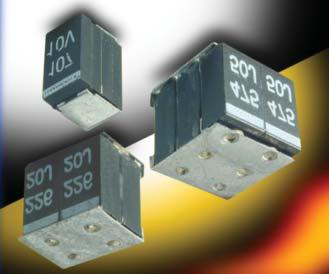
29 TCP Series - DSCC TCP Series Low ESR Tantalum Modules TCP Series tantalum modules represent high packing density for applications utilizing multiple components in a parallel configuration, and are available with testing to DSCC These modules feature stacked assemblies of CWR29 capacitors which provide ultra low ESR and utilize established reliability capacitors (Weibull Grade voltage conditioning) in accordance with MIL-PRF They can also be supplied with SRC9000 Space Level components. The stacked construction of fully molded capacitors is compatible with a wide range of SMT board assembly processes including reflow solder or conductive epoxy. There are two termination finishes available: hot solder dipped ( C ) and gold plated ( B ). The molding compound has been selected to meet the requirements of UL94V-0 and outgassing requirements of ASTM E-595. For moisture sensitivity levels please refer to the High Reliability Tantalum MSL section located in the back of the High Reliability Tantalum Catalog. DIMENSIONS Note: Additional form factors and ratings are available. Contact plant for details. W L L W H H P P W1 Solderable Surface (see Note 1) CASE DIMENSIONS: CAPACITANCE AND RATED VOLTAGE CASE SIZE (ESR IN m ) millimeters (inches) Case Length (L) Width (W) Height (H) Term. Width (W 1 ) Term. Length (P) ±0.38 (0.015) ±0.38 (0.015) ±0.38 (0.015) ±0.38 (0.015) For Reference Only 2H 7.82 (0.308) 4.06 (0.160) 6.10 (0.240) 4.06 (0.160) 1.52 (0.060) 4H 7.82 (0.308) 8.13 (0.320) 6.10 (0.240) 8.13 (0.320) 1.52 (0.060) 6H 7.82 (0.308) 8.13 (0.320) 9.14 (0.360) 8.13 (0.320) 1.52 (0.060) Additional form factors and ratings are available contact plant for details. Rated voltage DC (V R ) to 85ºC μf 6V 10V 15V 20V 25V 35V 50V H (200) H (100) H (200) H (67) H (100) H (67) H (85) H (75) H (43) H (38) H (28) H (63) H (25) H (31) H (50) H (21) H (50) H (25) 1, H (25) 6H (17) 1, H (17)
30 TCP Series - DSCC TCP Series Low ESR Tantalum Modules HOW TO ORDER TC 2H 945 K 050 L R 0 ^ ++ Type Case Size pf code: 1st two digits represent significant figures 3rd digit represents multiplier (number of zeros to follow) Tolerance M = ±20% K = ±10% J = ±5% Voltage 006 = 6Vdc 010 = 10Vdc 015 = 15Vdc 020 = 20Vdc 025 = 25Vdc 035 = 35Vdc 050 = 50Vdc Standard or Low ESR Range L = Low ESR Packaging B = Bulk R = 7" T&R Inspection Level S = Std. Conformance L = Group A D = DSCC DWG Reliability Grade Weibull: B = 0.1%/1000 hrs. 90% conf. C = 0.01%/1000 hrs. 90% conf. D = 0.001%/1000 hrs. 90% conf. Z = Non-ER Qualification Level 0 = N/A 9 = SRC9000 Termination Finish 8 = Hot Solder Dipped 9 = Gold Plated LEAD-FREE COMPATIBLE COMPONENT For RoHS compliant products, please select correct termination style. Surge Test Option 00 = None 23 = 10 Cycles, +25ºC 24 = 10 Cycles, -55ºC & +85ºC 45 = 10 cycles, -55ºC & +85ºC before Weibull DSCC DWG P/N: K B C A DSCC DWG Dash Number See Rating Tables Tolerance K = ±10% M = ±20% Reliability Grade B = B Weibull C = C Weibull D = D Weibull Termination Finish B = Gold Plated (10 microinch minimum) C = Hot Solder Dip (60 microinch minimum) LEAD-FREE COMPATIBLE COMPONENT For RoHS compliant products, please select correct termination style. Surge Test Option A = 10 cycles, +25 C B = 10 cycles, -55 C & +85 C C = 10 cycles, -55 C & +85 C before Weibull Z = None required Per MIL-PRF TECHNICAL SPECIFICATIONS Technical Data: Unless otherwise specified, all technical data relate to an ambient temperature of 25 C Range: 9.4 μf to 1,980 μf Tolerance: ±5%; ±10%; ±20% Rated Voltage (V R ) 85 C: Category Voltage (V C ) 125 C: Surge Voltage (V S ) 85 C: Surge Voltage (V S ) 125 C: Temperature Range: -55 C to +125 C
31 TCP Series TCP Series Low ESR Tantalum Modules RATINGS & PART NUMBER REFERENCE 2-STACK Parametric Specifications by Rating Typical RMS Ripple Data by Rating AVX P/N DSCC P/N Case ESR 100kHz Ripple Current Rating 100kHz Ripple Voltage Rating Cap Volt DC Leakage (max) μa Disspation Factor (max) 100 khz A A A V V V μf V +25 C mω +25 C +85 C +125 C +25 C +(85/125) C -55 C +25 C +85 C +125 C +25 C +85 C +125 C TC2H667*006L #@ *@^+ 2H TC2H447*010L #@ *@^+ 2H TC2H207*015L #@ *@^+ 2H TC2H946*020L #@ *@^+ 2H TC2H666*025L #@ *@^+ 2H TC2H206*035L #@ *@^+ 2H TC2H945*050L #@ *@^+ 2H STACK Parametric Specifications by Rating Typical RMS Ripple Data by Rating AVX P/N DSCC P/N Case ESR 100kHz Ripple Current Rating 100kHz Ripple Voltage Rating Cap Volt DC Leakage (max) μa Disspation Factor (max) 100 khz A A A V V V μf V +25 C mω +25 C +85 C +125 C +25 C +(85/125) C -55 C +25 C +85 C +125 C +25 C +85 C +125 C TC4H138*006L #@ *@^+ 4H TC4H887*010L #@ *@^+ 4H TC4H407*015L #@ *@^+ 4H TC4H197*020L #@ *@^+ 4H TC4H137*025L #@ *@^+ 4H TC4H406*035L #@ *@^+ 4H TC4H196*050L #@ *@^+ 4H STACK Parametric Specifications by Rating Typical RMS Ripple Data by Rating AVX P/N DSCC P/N Case ESR 100kHz Ripple Current Rating 100kHz Ripple Voltage Rating Cap Volt DC Leakage (max) μa Disspation Factor (max) 100 khz A A A V V V μf V +25 C mω +25 C +85 C +125 C +25 C +(85/125) C -55 C +25 C +85 C +125 C +25 C +85 C +125 C TC6H208*006L #@ *@^+ 6H TC6H138*010L #@ *@^+ 6H TC6H607*015L #@ *@^+ 6H TC6H287*020L #@ *@^+ 6H TC6H207*025L #@ *@^+ 6H TC6H606*035L #@ *@^+ 6H TC6H286*050L #@ *@^+ 6H All technical data relates to an ambient temperature of +25 C. and DF are measured at 120Hz, 0.5V RMS with a maximum DC bias of 2.2 volts. DCL is measured at rated voltage after 5 minutes. NOTE: AVX reserves the right to supply a higher voltage rating or tighter tolerance part in the same case size, to the same reliability standards
.")
 available.")
32 TBJ Series CWR11 - MIL-PRF-55365/8 Established Reliability, COTS-Plus & Space Level L A S A W 1 H W Fully qualified to MIL-PRF-55365/8, the CWR11 is the military version of EIA- 535BAAC, with four case sizes designed for maximum packaging efficiency on 8mm & 12mm tape for high volume production (ensuring no TCE mismatch with any substrate). This construction is compatible with a wide range of SMT board assembly processes including wave or reflow solder, conductive epoxy or compression bonding techniques. The part also carries full polarity, capacitance / voltage and JAN brand marking. The series is qualified to MIL-PRF Weibull B, C, D and T levels, with all surge options ( A, B & C ) available. For Space Level applications, AVX SRC9000 qualification is recommended (see ratings table for part number availability). There are four termination finishes available: solder plated, fused solder plated, hot solder dipped and gold plated (these are H, K, C and B termination, respectively, per MIL-PRF-55365). The molding compound has been selected to meet the requirements of UL94V-0 (Flame Retardancy) and outgassing requirements of ASTM E-595. For moisture sensitivity levels please refer to the High Reliability Tantalum MSL section located in the back of the High Reliability Tantalum Catalog. MARKING (Brown marking on gold body) Polarity Stripe (+) J for JAN Brand Rated Voltage Manufacturer s ID CASE DIMENSIONS: millimeters (inches) Case EIA Term. Width (W 1 ) Term. Length A Length (L) Width (W) Height (H) S min Metric ±0.10 (±0.004) ±0.30(±0.012) A B C D ± ± ± (0.047) 0.80 (0.031) 1.80 (0.071) (0.126±0.008) (0.063±0.008) (0.063±0.008) 3.50± ± ± (0.087) 0.80 (0.031) 1.40 (0.055) (0.138±0.008) (0.110±0.008) (0.075±0.008) 6.00± ± ± (0.087) 1.30 (0.051) 2.90 (0.114) (0.236±0.012) (0.126±0.012) (0.098±0.012) 7.30± ± ± (0.094) 1.30 (0.051) 4.40 (0.173) (0.287±0.012) (0.169±0.012) (0.110±0.012) CAPACITANCE AND RATED VOLTAGE, V R (MIL VOLTAGE CODE) RANGE CASE SIZE Rated voltage DC (V R ) to 85ºC μf 4V (C) 6V (D) 10V (F) 15V (H) 20V (J) 25V (K) 35V (M) 50V (N) A A A B A B A A B A A B C A A B B C A A A B B C A A A B B C D A A A B B C C D A B B B C C D A B B B C C D D B B B C D D B B C D B C C D D C D D C D D D D D D D
33 TBJ Series CWR11 - MIL-PRF-55365/8 Established Reliability, COTS-Plus & Space Level HOW TO ORDER COTS-PLUS & MIL QPL (CWR11): TBJ D 686 * 006 C 0 ^ ++ Type Case Size pf code: 1st two digits represent significant figures 3rd digit represents multiplier (number of zeros to follow) Tolerance M = ±20% K = ±10% J = ±5% Voltage 004 = 4Vdc 006 = 6Vdc 010 = 10Vdc 015 = 15Vdc 020 = 20Vdc 025 = 25Vdc 035 = 35Vdc 050 = 50Vdc Standard or Low ESR Range C = Std ESR Packaging B = Bulk R = 7" T&R S = 13" T&R W = Waffle See page 8 for additional packaging options. Inspection Level S = Std. Conformance L = Group A M = MIL (JAN) CWR11 Reliability Grade Weibull: B = 0.1%/1000 hrs. 90% conf. C = 0.01%/1000 hrs. 90% conf. D = 0.001%/1000 hrs. 90% conf. Z = Non-ER Qualification Level 0 = N/A T = T Level 9 = SRC9000 Termination Finish H = Solder Plated 0 = Fused Solder Plated 8 = Hot Solder Dipped 9 = Gold Plated 7 = Matte Sn (COTS-Plus only) Surge Test Option 00 = None 23 = 10 Cycles, +25ºC 24 = 10 Cycles, -55ºC & +85ºC 45 = 10 cycles, -55ºC & +85ºC before Weibull LEAD-FREE COMPATIBLE COMPONENT CWR11 P/N CROSS REFERENCE: For RoHS compliant products, please select correct termination style. CWR11 D ^ Type Voltage C = 4Vdc D = 6Vdc F = 10Vdc H = 15Vdc J = 20Vdc K = 25Vdc M = 35Vdc N = 50Vdc Termination Finish H = Solder Plated K = Solder Fused C = Hot Solder Dipped B = Gold Plated LEAD-FREE COMPATIBLE COMPONENT pf code: 1st two digits represent significant figures 3rd digit represents multiplier (number of zeros to follow) Tolerance M = ±20% K = ±10% J = ±5% Reliability Grade Weibull: B = 0.1%/1000 hrs. 90% conf. C = 0.01%/1000 hrs. 90% conf. D = 0.001%/1000 hrs. 90% conf. T = T Level A = Non-ER Surge Test Option A = 10 cycles, +25 C B = 10 cycles, -55 C & +85 C C = 10 cycles, -55 C & +85 C before Weibull If blank, None required Packaging Bulk = Standard \TR = 7" T&R \TR13 = 13" T&R \W = Waffle See page 8 for additional packaging options. For RoHS compliant products, please select correct termination style. SPACE LEVEL OPTIONS TO SRC9000*: TBJ D 686 * 006 C 9 ^ ++ Type Case Size pf code: 1st two digits represent significant figures 3rd digit represents multiplier (number of zeros to follow) Tolerance M = ±20% K = ±10% J = ±5% Voltage 004 = 4Vdc 006 = 6Vdc 010 = 10Vdc 015 = 15Vdc 020 = 20Vdc 025 = 25Vdc 035 = 35Vdc 050 = 50Vdc Standard or Low ESR Range C = Std ESR Packaging B = Bulk R = 7" T&R S = 13" T&R W = Waffle See page 8 for additional packaging options. Inspection Level L = Group A Reliability Grade Weibull: B = 0.1%/1000 hrs. 90% conf. C = 0.01%/1000 hrs. 90% conf. D = 0.001%/1000 hrs. 90% conf. Qualification Level 9 = SRC9000 Termination Finish H = Solder Plated 0 = Fused Solder Plated 8 = Hot Solder Dipped 9 = Gold Plated Surge Test Option 45 = 10 cycles, -55ºC & +85ºC before Weibull *Contact factory for AVX SRC9000 Space Level SCD details. LEAD-FREE COMPATIBLE COMPONENT For RoHS compliant products, please select correct termination style. TECHNICAL SPECIFICATIONS Technical Data: Unless otherwise specified, all technical data relate to an ambient temperature of 25 C Range: 0.10 μf to 100 μf Tolerance: ±5%; ±10%; ±20% Rated Voltage (V R ) 85 C: Category Voltage (V C ) 125 C: Surge Voltage (V S ) 85 C: Surge Voltage (V S ) 125 C: Temperature Range: -55 C to +125 C
34 TBJ Series CWR11 - MIL-PRF-55365/8 Established Reliability, COTS-Plus & Space Level Parametric Specifications by Rating per MIL-PRF-55365/8 Typical RMS Ripple Data by Rating RATING & PART NUMBER REFERENCE Cap DC Rated ESR DCL max DF Max Power 25ºC 85ºC 125ºC 25ºC 85ºC 120Hz 100kHz +25ºC +85ºC +125ºC +25ºC +(85/125)ºC -55ºC Dissipation Ripple Ripple Ripple Ripple Ripple Ripple CWR11 P/N AVX COTS-Plus P/N AVX SRC9000 P/N Case μf V Ohms A A A V V V (μa) (μa) (μa) (%) (%) (%) +25ºC (100kHz) (100kHz) (100kHz) (100kHz) (100kHz) (100kHz) CWR11C^225*@+ TBJA 225 * 004 C 0 ^ ++ TBJ A 225 * 004 C 9 ^ ++ A CWR11C^475*@+ TBJ A 475 * 004 C 0 ^ ++ TBJ A 475 * 004 C 9 ^ ++ A CWR11C^685*@+ TBJ B 685 * 004 C 0 ^ ++ TBJ B 685 * 004 C 9 ^ ++ B CWR11C^106*@+ TBJ B 106 * 004 C 0 ^ ++ TBJ B 106 * 004 C 9 ^ ++ B CWR11C^156*@+ TBJ B 156 * 004 C 0 ^ ++ TBJ B 156 * 004 C 9 ^ ++ B CWR11C^336*@+ TBJ C 336 * 004 C 0 ^ ++ TBJ C 336 * 004 C 9 ^ ++ C CWR11C^686*@+ TBJ D 686 * 004 C 0 ^ ++ TBJ D 686 * 004 C 9 ^ ++ D CWR11C^107*@+ TBJ D 107 * 004 C 0 ^ ++ TBJ D 107 * 004 C 9 ^ ++ D CWR11D^155*@+ TBJ A 155 * 006 C 0 ^ ++ TBJ A 155 * 006 C 9 ^ ++ A CWR11D^225*@+ TBJ A 225 * 006 C 0 ^ ++ TBJ A 225 * 006 C 9 ^ ++ A CWR11D^335*@+ TBJ A 335 * 006 C 0 ^ ++ TBJ A 335 * 006 C 9 ^ ++ A CWR11D^475*@+ TBJ B 475 * 006 C 0 ^ ++ TBJ B 475 * 006 C 9 ^ ++ B CWR11D^685*@+ TBJ B 685 * 006 C 0 ^ ++ TBJ B 685 * 006 C 9 ^ ++ B CWR11D^106*@+ TBJ B 106 * 006 C 0 ^ ++ TBJ B 106 * 006 C 9 ^ ++ B CWR11D^156*@+ TBJ C 156 * 006 C 0 ^ ++ TBJ C 156 * 006 C 9 ^ ++ C CWR11D^226*@+ TBJ C 226 * 006 C 0 ^ ++ TBJ C 226 * 006 C 9 ^ ++ C CWR11D^476*@+ TBJ D 476 * 006 C 0 ^ ++ TBJ D 476 * 006 C 9 ^ ++ D CWR11D^686*@+ TBJ D 686 * 006 C 0 ^ ++ TBJ D 686 * 006 C 9 ^ ++ D CWR11F^105*@+ TBJ A 105 * 010 C 0 ^ ++ TBJ A 105 * 010 C 9 ^ ++ A CWR11F^155*@+ TBJ A 155 * 010 C 0 ^ ++ TBJ A 155 * 010 C 9 ^ ++ A CWR11F^225*@+ TBJ A 225 * 010 C 0 ^ ++ TBJ A 225 * 010 C 9 ^ ++ A CWR11F^335*@+ TBJ B 335 * 010 C 0 ^ ++ TBJ B 335 * 010 C 9 ^ ++ B CWR11F^475*@+ TBJ B 475 * 010 C 0 ^ ++ TBJ B 475 * 010 C 9 ^ ++ B CWR11F^685*@+ TBJ B 685 * 010 C 0 ^ ++ TBJ B 685 * 010 C 9 ^ ++ B CWR11F^156*@+ TBJ C 156 * 010 C 0 ^ ++ TBJ C 156 * 010 C 9 ^ ++ C CWR11F^336*@+ TBJ D 336 * 010 C 0 ^ ++ TBJ D 336 * 010 C 9 ^ ++ D CWR11F^476*@+ TBJ D 476 * 010 C 0 ^ ++ TBJ D 476 * 010 C 9 ^ ++ D CWR11H^684*@+ TBJ A 684 * 015 C 0 ^ ++ TBJ A 684 * 015 C 9 ^ ++ A CWR11H^105*@+ TBJ A 105 * 015 C 0 ^ ++ TBJ A 105 * 015 C 9 ^ ++ A CWR11H^155*@+ TBJ A 155 * 015 C 0 ^ ++ TBJ A 155 * 015 C 9 ^ ++ A CWR11H^225*@+ TBJ B 225 * 015 C 0 ^ ++ TBJ B 225 * 015 C 9 ^ ++ B CWR11H^335*@+ TBJ B 335 * 015 C 0 ^ ++ TBJ B 335 * 015 C 9 ^ ++ B CWR11H^475*@+ TBJ B 475 * 015 C 0 ^ ++ TBJ B 475 * 015 C 9 ^ ++ B CWR11H^106*@+ TBJ C 106 * 015 C 0 ^ ++ TBJ C 106 * 015 C 9 ^ ++ C CWR11H^226*@+ TBJ D 226 * 015 C 0 ^ ++ TBJ D 226 * 015 C 9 ^ ++ D CWR11H^336*@+ TBJ D 336 * 015 C 0 ^ ++ TBJ D 336 * 015 C 9 ^ ++ D CWR11J^474*@+ TBJ A 474 * 020 C 0 ^ ++ TBJ A 474 * 020 C 9 ^ ++ A CWR11J^684*@+ TBJ A 684 * 020 C 0 ^ ++ TBJ A 684 * 020 C 9 ^ ++ A CWR11J^105*@+ TBJ A 105 * 020 C 0 ^ ++ TBJ A 105 * 020 C 9 ^ ++ A CWR11J^155*@+ TBJ B 155 * 020 C 0 ^ ++ TBJ B 155 * 020 C 9 ^ ++ B CWR11J^225*@+ TBJ B 225 * 020 C 0 ^ ++ TBJ B 225 * 020 C 9 ^ ++ B CWR11J^335*@+ TBJ B 335 * 020 C 0 ^ ++ TBJ B 335 * 020 C 9 ^ ++ B CWR11J^475*@+ TBJ C 475 * 020 C 0 ^ ++ TBJ C 475 * 020 C 9 ^ ++ C CWR11J^685*@+ TBJ C 685 * 020 C 0 ^ ++ TBJ C 685 * 020 C 9 ^ ++ C CWR11J^156*@+ TBJ D 156 * 020 C 0 ^ ++ TBJ D 156 * 020 C 9 ^ ++ D CWR11J^226*@+ TBJ D 226 * 020 C 0 ^ ++ TBJ D 226 * 020 C 9 ^ ++ D CWR11K^334*@+ TBJ A 334 * 025 C 0 ^ ++ TBJ A 334 * 025 C 9 ^ ++ A CWR11K^474*@+ TBJ A 474 * 025 C 0 ^ ++ TBJ A 474 * 025 C 9 ^ ++ A CWR11K^684*@+ TBJ B 684 * 025 C 0 ^ ++ TBJ B 684 * 025 C 9 ^ ++ B CWR11K^105*@+ TBJ B 105 * 025 C 0 ^ ++ TBJ B 105 * 025 C 9 ^ ++ B CWR11K^155*@+ TBJ B 155 * 025 C 0 ^ ++ TBJ B 155 * 025 C 9 ^ ++ B CWR11K^225*@+ TBJ C 225 * 025 C 0 ^ ++ TBJ C 225 * 025 C 9 ^ ++ C CWR11K^335*@+ TBJ C 335 * 025 C 0 ^ ++ TBJ C 335 * 025 C 9 ^ ++ C CWR11K^475*@+ TBJ C 475 * 025 C 0 ^ ++ TBJ C 475 * 025 C 9 ^ ++ C CWR11K^685*@+ TBJ D 685 * 025 C 0 ^ ++ TBJ D 685 * 025 C 9 ^ ++ D All technical data relates to an ambient temperature of +25 C. and DF are measured at 120Hz, 0.5V RMS with a maximum DC bias of 2.2 volts. DCL is measured at rated voltage after 5 minutes. NOTE: AVX reserves the right to supply a higher voltage rating or tighter tolerance part in the same case size, to the same reliability standards
35 TBJ Series CWR11 - MIL-PRF-55365/8 Established Reliability, COTS-Plus & Space Level Parametric Specifications by Rating per MIL-PRF-55365/8 Typical RMS Ripple Data by Rating RATING & PART NUMBER REFERENCE Cap DC Rated ESR DCL max DF Max Power 25ºC 85ºC 125ºC 25ºC 85ºC 120Hz 100kHz +25ºC +85ºC +125ºC +25ºC +(85/125)ºC -55ºC Dissipation Ripple Ripple Ripple Ripple Ripple Ripple CWR11 P/N AVX COTS-Plus P/N AVX SRC9000 P/N Case μf V Ohms A A A V V V (μa) (μa) (μa) (%) (%) (%) +25ºC (100kHz) (100kHz) (100kHz) (100kHz) (100kHz) (100kHz) CWR11K^106*@+ TBJ D 106 * 025 C 0 ^ ++ TBJ D 106 * 025 C 9 ^ ++ D CWR11K^156*@+ TBJ D 156 * 025 C 0 ^ ++ TBJ D 156 * 025 C 9 ^ ++ D CWR11M^104*@+ TBJ A 104 * 035 C 0 ^ ++ TBJ A 104 * 035 C 9 ^ ++ A CWR11M^154*@+ TBJ A 154 * 035 C 0 ^ ++ TBJ A 154 * 035 C 9 ^ ++ A CWR11M^224*@+ TBJ A 224 * 035 C 0 ^ ++ TBJ A 224 * 035 C 9 ^ ++ A CWR11M^334*@+ TBJ A 334 * 035 C 0 ^ ++ TBJ A 334 * 035 C 9 ^ ++ A CWR11M^474*@+ TBJ B 474 * 035 C 0 ^ ++ TBJ B 474 * 035 C 9 ^ ++ B CWR11M^684*@+ TBJ B 684 * 035 C 0 ^ ++ TBJ B 684 * 035 C 9 ^ ++ B CWR11M^105*@+ TBJ B 105 * 035 C 0 ^ ++ TBJ B 105 * 035 C 9 ^ ++ B CWR11M^155*@+ TBJ C 155 * 035 C 0 ^ ++ TBJ C 155 * 035 C 9 ^ ++ C CWR11M^225*@+ TBJ C 225 * 035 C 0 ^ ++ TBJ C 225 * 035 C 9 ^ ++ C CWR11M^335*@+ TBJ C 335 * 035 C 0 ^ ++ TBJ C 335 * 035 C 9 ^ ++ C CWR11M^475*@+ TBJ D 475 * 035 C 0 ^ ++ TBJ D 475 * 035 C 9 ^ ++ D CWR11M^685*@+ TBJ D 685 * 035 C 0 ^ ++ TBJ D 685 * 035 C 9 ^ ++ D CWR11N^104*@+ TBJ A 104 * 050 C 0 ^ ++ TBJ A 104 * 050 C 9 ^ ++ A CWR11N^154*@+ TBJ B 154 * 050 C 0 ^ ++ TBJ B 154 * 050 C 9 ^ ++ B CWR11N^224*@+ TBJ B 224 * 050 C 0 ^ ++ TBJ B 224 * 050 C 9 ^ ++ B CWR11N^334*@+ TBJ B 334 * 050 C 0 ^ ++ TBJ B 334 * 050 C 9 ^ ++ B CWR11N^474*@+ TBJ C 474 * 050 C 0 ^ ++ TBJ C 474 * 050 C 9 ^ ++ C CWR11N^684*@+ TBJ C 684 * 050 C 0 ^ ++ TBJ C 684 * 050 C 9 ^ ++ C CWR11N^105*@+ TBJ C 105 * 050 C 0 ^ ++ TBJ C 105 * 050 C 9 ^ ++ C CWR11N^155*@+ TBJ D 155 * 050 C 0 ^ ++ TBJ D 155 * 050 C 9 ^ ++ D CWR11N^225*@+ TBJ D 225 * 050 C 0 ^ ++ TBJ D 225 * 050 C 9 ^ ++ D CWR11N^335*@+ TBJ D 335 * 050 C 0 ^ ++ TBJ D 335 * 050 C 9 ^ ++ D CWR11N^475*@+ TBJ D 475 * 050 C 0 ^ ++ TBJ D 475 * 050 C 9 ^ ++ D All technical data relates to an ambient temperature of +25 C. and DF are measured at 120Hz, 0.5V RMS with a maximum DC bias of 2.2 volts. DCL is measured at rated voltage after 5 minutes. NOTE: AVX reserves the right to supply a higher voltage rating or tighter tolerance part in the same case size, to the same reliability standards
, surge current testing (A, B, C) per MIL-PRF- 55365 Rev. G, and optional Group A from MIL-PRF-55365.")
36 TBJ Series COTS-Plus The TBJ COTS-Plus series, based on the CWR11 form factor, is a high reliability series encompassing the current range of EIA Low ESR ratings. These ratings are available with Weibull grading (B and C), surge current testing (A, B, C) per MIL-PRF Rev. G, and optional Group A from MIL-PRF For Space Level applications, AVX SRC9000 qualification is recommended. Please refer to the TBJ COTS-Plus SRC9000 Datasheet for part number availability. There are five termination finishes available: solder plated, fused solder plated, hot solder dipped, 100% Tin and gold plated (these correspond to H, K, C, 7 and B termination, respectively). The molding compound has been selected to meet the requirements of UL94V-0 (Flame Retardancy) and outgassing requirements of ASTM E-595. For moisture sensitivity levels please refer to the High Reliability Tantalum MSL section located in the back of the High Reliability Tantalum Catalog. CASE DIMENSIONS: millimeters (inches) L A S A W 1 MARKING A, B, C, D, E, V CASE Polarity Band (Anode+) AVX LOGO 227 A XXXXX H W Value in pf 227 = 220µF Rated Voltage A = 10V ID EIA EIA L±0.20 W+0.20 (0.008) H+0.20 (0.008) W 1 ±0.20 A+0.30 (0.012) Metric (0.008) (0.004) (0.004) (0.008) (0.008) S Min. A (0.126) 1.60 (0.063) 1.60 (0.063) 1.20 (0.047) 0.80 (0.031) 1.10 (0.043) B (0.138) 2.80 (0.110) 1.90 (0.075) 2.20 (0.087) 0.80 (0.031) 1.40 (0.055) C (0.236) 3.20 (0.126) 2.60 (0.102) 2.20 (0.087) 1.30 (0.051) 2.90 (0.114) D (0.287) 4.30 (0.169) 2.90 (0.114) 2.40 (0.094) 1.30 (0.051) 4.40 (0.173) E (0.287) 4.30 (0.169) 4.10 (0.162) 2.40 (0.094) 1.30 (0.051) 4.40 (0.173) V (0.287) 6.10 (0.240) 3.55 (0.140) 3.10 (0.120) 1.30 (0.051) 4.40 (0.173) W 1 dimension applies to the termination width for A dimensional area only. HOW TO ORDER AVX PART NUMBER: TBJ D 227 * 035 C B S Z Type Case Size pf code: 1st two digits represent significant figures 3rd digit represents multiplier (number of zeros to follow) Tolerance K = ±10% M = ±20% Voltage 002 = 2Vdc 004 = 4Vdc 006 = 6.3Vdc 010 = 10Vdc 016 = 16Vdc 020 = 20Vdc 025 = 25Vdc 035 = 35Vdc 050 = 50Vdc ESR C = Std ESR L = Low ESR Packaging B = Bulk R = 7" T&R S = 13" T&R W = Waffle Inspection Level S = Std. Conformance L = Group A Reliability Grade Weibull: B = 0.1%/1000 hrs. 90% conf. C = 0.01%/1000 hrs. 90% conf. Z = Non-ER Qualification Level 0 = N/A Termination Finish H = Solder Plated 0 = Fused Solder Plated 8 = Hot Solder Dipped 9 = Gold Plated 7 = Matte Sn Surge Test Option 00 = None 23 = 10 Cycles, +25ºC 24 = 10 Cycles, -55ºC & +85ºC 45 = 10 cycles, -55ºC & +85ºC before Weibull LEAD-FREE COMPATIBLE COMPONENT TECHNICAL SPECIFICATIONS For RoHS compliant products, please select correct termination style. Technical Data: Unless otherwise specified, all technical data relate to an ambient temperature of 25 C Range: 0.10 μf to 1500 μf Tolerance: ±10%; ±20% Rated Voltage (V R ) 85 C: Category Voltage (V C ) 125 C: Surge Voltage (V S ) 85 C: Surge Voltage (V S ) 125 C: Temperature Range: -55 C to +125 C
37 TBJ Series COTS-Plus CAPACITANCE AND RATED VOLTAGE, V R (VOLTAGE CODE) RANGE (LETTER DENOTES CASE SIZE) Rated Voltage DC (V R ) to 85 C μf 2V (e) 4V (G) 6V (J) 10V (A) 15V (H) 16V (C) 20V (D) 25V (E) 35V (V) 50V (T) A(24000) A(22000) A(21000) A(9000, 21000) B(17000) A(6000, 18000) A(7000, 18000) B(14000) A(6000, 15000) B(12000) A(14000) A(7000, 14000) A(6000, 12000) B(4000, 10000) C(8000) A(12000) A(12000) A(12000) A(6000, 10000) A(6000, 8000) A(7900) B(7500) B(8000) C(7000) A(10000) A(10000) A(10000) A(3000, 10000) A(8000) A(3000, 7500) B(6500) B(2000, 6500) C(2500, 6000) A(8000) A(8000) A(8000) A(7500) A(6500) A(3000, 7500) B(2500, 5200) C(1500, 5000) B(6000) B(1800, 6500) C(4500) D(4000) A(8000) A(8000) A(1800, 8000) B(5500) A(7000) A(1500, 4500) A(1800, 5500) A(3000, 5300) B(900, 4500) B(2000, 4200) B(5000) B(5000) C(3500) C(1000, 3500) D(1200, 2500) A(8000) B(5500) B(5000) A(1000, 1500) A(3500, 5000)` A(2500) B(750, 3500) B(1000, 3500) B(4500) B(1300, 4000) C(3500) C(700, 2500) D(800, 2000) A(8000) B(5500) A(1800, 4000) A(2800) B(700, 3100) A(1400, 5000) B(4000) A(2000, 4000) B(750, 3000) B(1500, 2800) C(600, 2200) B(4500) B(800, 3100) C(3000) C(2500) D(500, 1500) D(300, 1500) B(5500) A(1000) B(700, 2800) C (350, 1800) A(1800, 5000) A(1800, 4000) A(1500, 2500) B(600, 2500) C(500, 2000) D(500, 1300) B(4500) B(3500) B(60, 2500) C(700, 2400) D(1400) D(500, 1000) B(4000) A(1000, 3000) C (600, 1600) A(1500, 4000) A(1800, 3000) C(2500) B(500, 2800) B(1000, 2100) C (500, 1800) D (300,1000) E(400, 500) B(3500) B(2500) C(500, 2500) C (500, 1900) D(1200) E(200, 250) V(650) B(3500) A(1500, 3500) A(1000, 3200) B(500, 2000) B(3500) B(450,2800) B(800, 2500) C(400, 1700) C(220, 300) C(350, 1400) D(600) C(3000) C(2500) C(1800) D(1100) D(300, 1000) D(300, 900) E(250, 600) A(500, 3000) B(600, 2300) B(400, 600) B(375, 2500) B(700, 2400) D(1100) C(375, 1600) C(150, 1600) C(275, 1400) D(400, 900) C(2200) C(300, 1000) D(1100) D(200, 900) D(200, 900) E(300, 900) V(390, 600) A(700, 1700) A(3000) A(600) B(250, 1800) B(350) C(300, 1500) D(100, 900) D(300, 900) C(2200) B(600, 2200) C(150, 1600) D(900) C(300, 1500) D(100, 900) E(300, 900) E(100, 250) D(1100) D(200, 900) V(200) A(500) A(800) B(250, 350) B(250, 350) C(350, 1500) D(100, 200) D(250, 900) E(200, 250) C(300, 1600) C(200, 1200) D(150, 900) E(70, 250) E(80, 100) V(200, 400) D(1100) D(100, 900) D(1100) B(250, 1800) B(600) C(150, 1600) C(80, 1200) C(125, 200) D(70, 900) E(125, 200) D(900) D(100, 900) D(70, 900) E(150, 900) V(95) V(150, 200) B(400) A(1400) B(250, 400) C(200, 1200) D(125, 900) D(85, 100) B(200, 1600) C(150, 900) D(100, 900) E(100, 900) E(100, 150) D(900) E(125) V(85, 200) V(100) B(150) D(150, 900) B(250) C(50, 90) D(150, 900) E(100, 300) E(300) C(70,80) D(50, 900) E(100) V(45, 75) V(80) C(70, 1200) B(150, 200) D(40,900) D(100, 900) D(150, 900) E(100, 150) D(45) E(100) E(100, 900) V(75, 150) D(45, 50) D(150, 900) C(100) E(100, 900) E(60, 900) D(35, 45) V(100) V(60, 100) D(35) D(45, 60) D(45, 100) E(50, 900) E(50, 900) E(35) V(55, 100) V(60, 100) D(35, 50) D(45, 60) E(45, 60) E(35, 50) E(40, 60) V(35, 40) E(30, 40) E(60) V(25, 35) V(40, 50) D(100) E(50) E(50, 75) V(30, 40) V(50, 75) Available Ratings: ESR limits quoted in brackets (mohms) Not recommended for new designs, higher voltage or smaller case size substitution are offered. Notes: Voltage ratings are minimum values. AVX reserves the right to supply higher ratings in the same case size, to the same reliability standards
38 TBJ Series COTS-Plus RATING & PART NUMBER REFERENCE Parametric Specifications by Rating per MIL-PRF-55365/4 Typical RMS Ripple Data by Rating Cap DC Rated ESR DCL max DF Max Power 25ºC 85ºC 125ºC 25ºC 85ºC 120Hz 100kHz +25ºC +85ºC +125ºC +25ºC +(85/125)ºC -55ºC Dissipation Ripple Current Ripple Current Ripple Current Ripple Voltage Ripple Voltage Ripple Voltage AVX COTS-Plus P/N Case μf V Ohms A A A V V V (μa) (μa) (μa) (%) (%) (%) +25ºC (100kHz) (100kHz) (100kHz) (100kHz) (100kHz) (100kHz) TBJB157*002L #@0^++ B TBJB227*002C #@0^++ B TBJB227*002L #@0^++ B TBJD227*002L #@0^++ D TBJD477*002L #@0^++ D TBJD687*002C #@0^++ D TBJD687*002L #@0^++ D TBJE687*002C #@0^++ E TBJE687*002L #@0^++ E TBJE108*002C #@0^++ E TBJE108*002L #@0^++ E TBJD158*002L #@0^++ D TBJE158*002L #@0^++ E TBJV158*002C #@0^++ V TBJV158*002L #@0^++ V TBJA225*004C #@0^++ A TBJA475*004C #@0^++ A TBJB685*004C #@0^++ B TBJB106*004C #@0^++ B TBJB156*004C #@0^++ B TBJA336*004C #@0^++ A TBJC336*004C #@0^++ C TBJA476*004L #@0^++ A TBJC686*004C #@0^++ C TBJD686*004C #@0^++ D TBJA107*004C #@0^++ A TBJB107*004C #@0^++ B TBJB107*004L #@0^++ B TBJB157*004L #@0^++ B TBJC157*004C #@0^++ C TBJC157*004L #@0^++ C TBJD227*004C #@0^++ D TBJD227*004L #@0^++ D TBJC337*004L #@0^++ C TBJD337*004C #@0^++ D TBJD337*004L #@0^++ D TBJD477*004C #@0^++ D TBJD477*004L #@0^++ D TBJE477*004L #@0^++ E TBJD687*004C #@0^++ D TBJD687*004L #@0^++ D TBJE687*004C #@0^++ E TBJE687*004L #@0^++ E TBJE108*004L #@0^++ E TBJV108*004C #@0^++ V TBJV108*004L #@0^++ V TBJE158*004C #@0^++ E TBJE158*004L #@0^++ E TBJV158*004C #@0^++ V TBJV158*004L #@0^++ V TBJA155*006C #@0^++ A TBJA225*006C #@0^++ A TBJA335*006C #@0^++ A TBJB475*006C #@0^++ B TBJA685*006C #@0^++ A TBJA685*006L #@0^++ A All technical data relates to an ambient temperature of +25 C. and DF are measured at 120Hz, 0.5V RMS with a maximum DC bias of 2.2 volts. DCL is measured at rated voltage after 5 minutes. NOTE: AVX reserves the right to supply a higher voltage rating or tighter tolerance part in the same case size, to the same reliability standards
39 TBJ Series COTS-Plus RATING & PART NUMBER REFERENCE AVX COTS-Plus P/N Case Parametric Specifications by Rating per MIL-PRF-55365/4 Typical RMS Ripple Data by Rating Cap DC Rated ESR DCL max DF Max Power 25ºC 85ºC 125ºC 25ºC 85ºC 120Hz 100kHz +25ºC +85ºC +125ºC +25ºC +(85/125)ºC -55ºC Dissipation Ripple Current Ripple Current Ripple Current Ripple Voltage Ripple Voltage Ripple Voltage μf V Ohms A A A V V V (μa) (μa) (μa) (%) (%) (%) +25ºC (100kHz) (100kHz) (100kHz) (100kHz) (100kHz) (100kHz) TBJB685*006C #@0^++ B TBJA106*006C #@0^++ A TBJA106*006L #@0^++ A TBJB106*006C #@0^++ B TBJA156*006C #@0^++ A TBJA156*006L #@0^++ A TBJB156*006C #@0^++ B TBJC156*006C #@0^++ C TBJA226*006C #@0^++ A TBJA226*006L #@0^++ A TBJB226*006C #@0^++ B TBJB226*006L #@0^++ B TBJC226*006C #@0^++ C TBJA336*006L #@0^++ A TBJB336*006C #@0^++ B TBJB336*006L #@0^++ B TBJA476*006L #@0^++ A TBJB476*006C #@0^++ B TBJB476*006L #@0^++ B TBJC476*006C #@0^++ C TBJC476*006L #@0^++ C TBJD476*006C #@0^++ D TBJB686*006C #@0^++ B TBJB686*006L #@0^++ B TBJC686*006C #@0^++ C TBJC686*006L #@0^++ C TBJD686*006C #@0^++ D TBJB107*006C #@0^++ B TBJB107*006L #@0^++ B TBJC107*006C #@0^++ C TBJC107*006L #@0^++ C TBJD107*006C #@0^++ D TBJC157*006C #@0^++ C TBJC157*006L #@0^++ C TBJD157*006C #@0^++ D TBJD157*006L #@0^++ D TBJC227*006C #@0^++ C TBJC227*006L #@0^++ C TBJD227*006C #@0^++ D TBJD227*006L #@0^++ D TBJE227*006L #@0^++ E TBJD337*006C #@0^++ D TBJD337*006L #@0^++ D TBJE337*006C #@0^++ E TBJE337*006L #@0^++ E TBJV337*006L #@0^++ V TBJD477*006C #@0^++ D TBJD477*006L #@0^++ D TBJE477*006C #@0^++ E TBJE477*006L #@0^++ E TBJV477*006C #@0^++ V TBJV477*006L #@0^++ V TBJE687*006C #@0^++ E TBJE687*006L #@0^++ E TBJV687*006C #@0^++ V TBJV687*006L #@0^++ V All technical data relates to an ambient temperature of +25 C. and DF are measured at 120Hz, 0.5V RMS with a maximum DC bias of 2.2 volts. DCL is measured at rated voltage after 5 minutes. NOTE: AVX reserves the right to supply a higher voltage rating or tighter tolerance part in the same case size, to the same reliability standards
40 TBJ Series COTS-Plus RATING & PART NUMBER REFERENCE Parametric Specifications by Rating per MIL-PRF-55365/4 Typical RMS Ripple Data by Rating Cap DC Rated ESR DCL max DF Max Power 25ºC 85ºC 125ºC 25ºC 85ºC 120Hz 100kHz +25ºC +85ºC +125ºC +25ºC +(85/125)ºC -55ºC Dissipation Ripple Current Ripple Current Ripple Current Ripple Voltage Ripple Voltage Ripple Voltage AVX COTS-Plus P/N Case μf V Ohms A A A V V V (μa) (μa) (μa) (%) (%) (%) +25ºC (100kHz) (100kHz) (100kHz) (100kHz) (100kHz) (100kHz) TBJV108*006C #@0^++ V TBJV108*006L #@0^++ V TBJA105*010C #@0^++ A TBJA155*010C #@0^++ A TBJA225*010C #@0^++ A TBJA225*010L #@0^++ A TBJB335*010C #@0^++ B TBJA475*010C #@0^++ A TBJA475*010L #@0^++ A TBJB475*010C #@0^++ B TBJA685*010C #@0^++ A TBJA685*010L #@0^++ A TBJB685*010C #@0^++ B TBJA106*010C #@0^++ A TBJA106*010L #@0^++ A TBJB106*010C #@0^++ B TBJA156*010C #@0^++ A TBJA156*010L #@0^++ A TBJB156*010C #@0^++ B TBJB156*010L #@0^++ B TBJC156*010C #@0^++ C TBJB226*010C #@0^++ B TBJB226*010L #@0^++ B TBJC226*010C #@0^++ C TBJC226*010L #@0^++ C TBJA336*010C #@0^++ A TBJA336*010L #@0^++ A TBJB336*010C #@0^++ B TBJB336*010L #@0^++ B TBJC336*010C #@0^++ C TBJC336*010L #@0^++ C TBJD336*010C #@0^++ D TBJB476*010C #@0^++ B TBJB476*010L #@0^++ B TBJC476*010C #@0^++ C TBJC476*010L #@0^++ C TBJD476*010C #@0^++ D TBJD476*010L #@0^++ D TBJB686*010L #@0^++ B TBJC686*010C #@0^++ C TBJC686*010L #@0^++ C TBJD686*010C #@0^++ D TBJD686*010L #@0^++ D TBJB107*010L #@0^++ B TBJC107*010C #@0^++ C TBJC107*010L #@0^++ C TBJD107*010C #@0^++ D TBJD107*010L #@0^++ D TBJE107*010C #@0^++ E TBJD157*010C #@0^++ D TBJD157*010L #@0^++ D TBJE157*010C #@0^++ E TBJD227*010C #@0^++ D TBJD227*010L #@0^++ D TBJE227*010C #@0^++ E TBJE227*010L #@0^++ E All technical data relates to an ambient temperature of +25 C. and DF are measured at 120Hz, 0.5V RMS with a maximum DC bias of 2.2 volts. DCL is measured at rated voltage after 5 minutes. NOTE: AVX reserves the right to supply a higher voltage rating or tighter tolerance part in the same case size, to the same reliability standards
41 TBJ Series COTS-Plus RATING & PART NUMBER REFERENCE Parametric Specifications by Rating per MIL-PRF-55365/4 Typical RMS Ripple Data by Rating Cap DC Rated ESR DCL max DF Max Power 25ºC 85ºC 125ºC 25ºC 85ºC 120Hz 100kHz +25ºC +85ºC +125ºC +25ºC +(85/125)ºC -55ºC Dissipation Ripple Current Ripple Current Ripple Current Ripple Voltage Ripple Voltage Ripple Voltage AVX COTS-Plus P/N Case μf V Ohms A A A V V V (μa) (μa) (μa) (%) (%) (%) +25ºC (100kHz) (100kHz) (100kHz) (100kHz) (100kHz) (100kHz) TBJD337*010L #@0^++ D TBJE337*010C #@0^++ E TBJE337*010L #@0^++ E TBJV337*010C #@0^++ V TBJV337*010L #@0^++ V TBJE477*010C #@0^++ E TBJE477*010L #@0^++ E TBJV477*010C #@0^++ V TBJV477*010L #@0^++ V TBJA684*015C #@0^++ A TBJA105*015C #@0^++ A TBJA155*015C #@0^++ A TBJB225*015C #@0^++ B TBJB335*015C #@0^++ B TBJB475*015C #@0^++ B TBJC106*015C #@0^++ C TBJD226*015C #@0^++ D TBJD336*015C #@0^++ D TBJD157*015L #@0^++ D TBJA684*016C #@0^++ A TBJA105*016C #@0^++ A TBJA225*016C #@0^++ A TBJA225*016L #@0^++ A TBJB225*016C #@0^++ B TBJA335*016C #@0^++ A TBJA335*016L #@0^++ A TBJB335*016C #@0^++ B TBJA475*016C #@0^++ A TBJA475*016L #@0^++ A TBJB475*016C #@0^++ B TBJB475*016L #@0^++ B TBJA685*016C #@0^++ A TBJA685*016L #@0^++ A TBJB685*016C #@0^++ B TBJB685*016L #@0^++ B TBJA106*016C #@0^++ A TBJA106*016L #@0^++ A TBJB106*016C #@0^++ B TBJB106*016L #@0^++ B TBJC106*016C #@0^++ C TBJC106*016L #@0^++ C TBJB156*016C #@0^++ B TBJB156*016L #@0^++ B TBJC156*016C #@0^++ C TBJB226*016C #@0^++ B TBJB226*016L #@0^++ B TBJC226*016C #@0^++ C TBJC226*016L #@0^++ C TBJD226*016C #@0^++ D TBJB336*016L #@0^++ B TBJC336*016C #@0^++ C TBJC336*016L #@0^++ C TBJD336*016C #@0^++ D TBJD336*016L #@0^++ D TBJC476*016C #@0^++ C TBJC476*016L #@0^++ C TBJD476*016C #@0^++ D TBJD476*016L #@0^++ D All technical data relates to an ambient temperature of +25 C. and DF are measured at 120Hz, 0.5V RMS with a maximum DC bias of 2.2 volts. DCL is measured at rated voltage after 5 minutes. NOTE: AVX reserves the right to supply a higher voltage rating or tighter tolerance part in the same case size, to the same reliability standards
42 TBJ Series COTS-Plus RATING & PART NUMBER REFERENCE Parametric Specifications by Rating per MIL-PRF-55365/4 Typical RMS Ripple Data by Rating Cap DC Rated ESR DCL max DF Max Power 25ºC 85ºC 125ºC 25ºC 85ºC 120Hz 100kHz +25ºC +85ºC +125ºC +25ºC +(85/125)ºC -55ºC Dissipation Ripple Current Ripple Current Ripple Current Ripple Voltage Ripple Voltage Ripple Voltage AVX COTS-Plus P/N Case μf V Ohms A A A V V V (μa) (μa) (μa) (%) (%) (%) +25ºC (100kHz) (100kHz) (100kHz) (100kHz) (100kHz) (100kHz) TBJC686*016C #@0^++ C TBJC686*016L #@0^++ C TBJD686*016C #@0^++ D TBJD686*016L #@0^++ D TBJD107*016C #@0^++ D TBJD107*016L #@0^++ D TBJE107*016C #@0^++ E TBJE107*016L #@0^++ E TBJD157*016C #@0^++ D TBJD157*016L #@0^++ D TBJE157*016C #@0^++ E TBJE157*016L #@0^++ E TBJV157*016C #@0^++ V TBJV157*016L #@0^++ V TBJE227*016C #@0^++ E TBJE227*016L #@0^++ E TBJV227*016C #@0^++ V TBJV227*016L #@0^++ V TBJA474*020C #@0^++ A TBJA684*020C #@0^++ A TBJA105*020C #@0^++ A TBJA105*020L #@0^++ A TBJA155*020C #@0^++ A TBJB155*020C #@0^++ B TBJA225*020C #@0^++ A TBJA225*020L #@0^++ A TBJB225*020C #@0^++ B TBJA335*020L #@0^++ A TBJB335*020C #@0^++ B TBJB335*020L #@0^++ B TBJA475*020C #@0^++ A TBJA475*020L #@0^++ A TBJB475*020C #@0^++ B TBJB475*020L #@0^++ B TBJC475*020C #@0^++ C TBJA685*020L #@0^++ A TBJB685*020C #@0^++ B TBJB685*020L #@0^++ B TBJC685*020C #@0^++ C TBJC685*020L #@0^++ C TBJB106*020C #@0^++ B TBJB106*020L #@0^++ B TBJC106*020C #@0^++ C TBJC106*020L #@0^++ C TBJB156*020C #@0^++ B TBJB156*020L #@0^++ B TBJC156*020C #@0^++ C TBJC156*020L #@0^++ C TBJD156*020C #@0^++ D TBJB226*020C #@0^++ B TBJB226*020L #@0^++ B TBJC226*020C #@0^++ C TBJC226*020L #@0^++ C TBJD226*020C #@0^++ D TBJD226*020L #@0^++ D TBJC336*020C #@0^++ C All technical data relates to an ambient temperature of +25 C. and DF are measured at 120Hz, 0.5V RMS with a maximum DC bias of 2.2 volts. DCL is measured at rated voltage after 5 minutes. NOTE: AVX reserves the right to supply a higher voltage rating or tighter tolerance part in the same case size, to the same reliability standards
43 TBJ Series COTS-Plus RATING & PART NUMBER REFERENCE Parametric Specifications by Rating per MIL-PRF-55365/4 Typical RMS Ripple Data by Rating Cap DC Rated ESR DCL max DF Max Power 25ºC 85ºC 125ºC 25ºC 85ºC 120Hz 100kHz +25ºC +85ºC +125ºC +25ºC +(85/125)ºC -55ºC Dissipation Ripple Current Ripple Current Ripple Current Ripple Voltage Ripple Voltage Ripple Voltage AVX COTS-Plus P/N Case μf V Ohms A A A V V V (μa) (μa) (μa) (%) (%) (%) +25ºC (100kHz) (100kHz) (100kHz) (100kHz) (100kHz) (100kHz) TBJC336*020L #@0^++ C TBJD336*020C #@0^++ D TBJD336*020L #@0^++ D TBJD476*020C #@0^++ D TBJD476*020L #@0^++ D TBJE476*020C #@0^++ E TBJE476*020L #@0^++ E TBJD686*020C #@0^++ D TBJD686*020L #@0^++ D TBJE686*020C #@0^++ E TBJE686*020L #@0^++ E TBJD107*020C #@0^++ D TBJD107*020L #@0^++ D TBJE107*020C #@0^++ E TBJE107*020L #@0^++ E TBJV107*020C #@0^++ V TBJV107*020L #@0^++ V TBJE157*020C #@0^++ E TBJV157*020L #@0^++ V TBJA334*025C #@0^++ A TBJA474*025C #@0^++ A TBJA474*025L #@0^++ A TBJA684*025C #@0^++ A TBJA684*025L #@0^++ A TBJB684*025C #@0^++ B TBJA105*025C #@0^++ A TBJB105*025C #@0^++ B TBJA155*025C #@0^++ A TBJA155*025L #@0^++ A TBJB155*025C #@0^++ B TBJB155*025L #@0^++ B TBJB225*025C #@0^++ B TBJB225*025L #@0^++ B TBJC225*025C #@0^++ C TBJA335*025C #@0^++ A TBJA335*025L #@0^++ A TBJB335*025C #@0^++ B TBJB335*025L #@0^++ B TBJC335*025C #@0^++ C TBJA475*025C #@0^++ A TBJB475*025C #@0^++ B TBJB475*025L #@0^++ B TBJC475*025C #@0^++ C TBJB685*025C #@0^++ B TBJB685*025L #@0^++ B TBJC685*025C #@0^++ C TBJC685*025L #@0^++ C TBJD685*025C #@0^++ D TBJC106*025C #@0^++ C TBJC106*025L #@0^++ C TBJD106*025C #@0^++ D TBJC156*025C #@0^++ C TBJC156*025L #@0^++ C TBJD156*025C #@0^++ D TBJD156*025L #@0^++ D TBJC226*025C #@0^++ C All technical data relates to an ambient temperature of +25 C. and DF are measured at 120Hz, 0.5V RMS with a maximum DC bias of 2.2 volts. DCL is measured at rated voltage after 5 minutes. NOTE: AVX reserves the right to supply a higher voltage rating or tighter tolerance part in the same case size, to the same reliability standards
44 TBJ Series COTS-Plus RATING & PART NUMBER REFERENCE Parametric Specifications by Rating per MIL-PRF-55365/4 Typical RMS Ripple Data by Rating Cap DC Rated ESR DCL max DF Max Power 25ºC 85ºC 125ºC 25ºC 85ºC 120Hz 100kHz +25ºC +85ºC +125ºC +25ºC +(85/125)ºC -55ºC Dissipation Ripple Current Ripple Current Ripple Current Ripple Voltage Ripple Voltage Ripple Voltage AVX COTS-Plus P/N Case μf V Ohms A A A V V V (μa) (μa) (μa) (%) (%) (%) +25ºC (100kHz) (100kHz) (100kHz) (100kHz) (100kHz) (100kHz) TBJC226*025L #@0^++ C TBJD226*025C #@0^++ D TBJD226*025L #@0^++ D TBJD336*025C #@0^++ D TBJD336*025L #@0^++ D TBJE336*025C #@0^++ E TBJE336*025L #@0^++ E TBJD476*025C #@0^++ D TBJD476*025L #@0^++ D TBJE476*025C #@0^++ E TBJE476*025L #@0^++ E TBJE686*025C #@0^++ E TBJE686*025L #@0^++ E TBJV686*025L #@0^++ V TBJV107*025L #@0^++ V TBJA104*035C #@0^++ A TBJA154*035C #@0^++ A TBJA224*035C #@0^++ A TBJA224*035L #@0^++ A TBJA334*035C #@0^++ A TBJA334*035L #@0^++ A TBJA474*035C #@0^++ A TBJA474*035L #@0^++ A TBJB474*035C #@0^++ B TBJB474*035L #@0^++ B TBJA684*035C #@0^++ A TBJA684*035L #@0^++ A TBJB684*035C #@0^++ B TBJA105*035C #@0^++ A TBJA105*035L #@0^++ A TBJB105*035C #@0^++ B TBJB105*035L #@0^++ B TBJA155*035C #@0^++ A TBJB155*035C #@0^++ B TBJB155*035L #@0^++ B TBJC155*035C #@0^++ C TBJA225*035C #@0^++ A TBJA225*035L #@0^++ A TBJB225*035C #@0^++ B TBJB225*035L #@0^++ B TBJC225*035C #@0^++ C TBJC225*035L #@0^++ C TBJB335*035C #@0^++ B TBJB335*035L #@0^++ B TBJC335*035C #@0^++ C TBJC335*035L #@0^++ C TBJB475*035C #@0^++ B TBJB475*035L #@0^++ B TBJC475*035C #@0^++ C TBJC475*035L #@0^++ C TBJD475*035C #@0^++ D TBJD475*035L #@0^++ D TBJC685*035C #@0^++ C TBJC685*035L #@0^++ C All technical data relates to an ambient temperature of +25 C. and DF are measured at 120Hz, 0.5V RMS with a maximum DC bias of 2.2 volts. DCL is measured at rated voltage after 5 minutes. NOTE: AVX reserves the right to supply a higher voltage rating or tighter tolerance part in the same case size, to the same reliability standards
45 TBJ Series COTS-Plus RATING & PART NUMBER REFERENCE Parametric Specifications by Rating per MIL-PRF-55365/4 Typical RMS Ripple Data by Rating Cap DC Rated ESR DCL max DF Max Power 25ºC 85ºC 125ºC 25ºC 85ºC 120Hz 100kHz +25ºC +85ºC +125ºC +25ºC +(85/125)ºC -55ºC Dissipation Ripple Current Ripple Current Ripple Current Ripple Voltage Ripple Voltage Ripple Voltage AVX COTS-Plus P/N Case μf V Ohms A A A V V V (μa) (μa) (μa) (%) (%) (%) +25ºC (100kHz) (100kHz) (100kHz) (100kHz) (100kHz) (100kHz) TBJD685*035C #@0^++ D TBJD685*035L #@0^++ D TBJC106*035C #@0^++ C TBJC106*035L #@0^++ C TBJD106*035C #@0^++ D TBJD106*035L #@0^++ D TBJE106*035C #@0^++ E TBJE106*035L #@0^++ E TBJC156*035C #@0^++ C TBJC156*035L #@0^++ C TBJD156*035C #@0^++ D TBJD156*035L #@0^++ D TBJD226*035C #@0^++ D TBJD226*035L #@0^++ D TBJE226*035C #@0^++ E TBJE226*035L #@0^++ E TBJD336*035C #@0^++ D TBJD336*035L #@0^++ D TBJE336*035C #@0^++ E TBJE336*035L #@0^++ E TBJV336*035L #@0^++ V TBJE476*035C #@0^++ E TBJE476*035L #@0^++ E TBJV476*035C #@0^++ V TBJV476*035L #@0^++ V TBJV686*035C #@0^++ V TBJV686*035L #@0^++ V TBJA104*050C #@0^++ A TBJA154*050C #@0^++ A TBJA154*050L #@0^++ A TBJB154*050C #@0^++ B TBJA224*050C #@0^++ A TBJA224*050L #@0^++ A TBJB224*050C #@0^++ B TBJB334*050C #@0^++ B TBJC474*050C #@0^++ C TBJA684*050C #@0^++ A TBJC684*050C #@0^++ C TBJC105*050C #@0^++ C TBJC105*050L #@0^++ C TBJC155*050C #@0^++ C TBJC155*050L #@0^++ C TBJD155*050C #@0^++ D TBJD225*050C #@0^++ D TBJD225*050L #@0^++ D TBJD335*050C #@0^++ D TBJD335*050L #@0^++ D TBJD475*050C #@0^++ D TBJD475*050L #@0^++ D TBJD685*050C #@0^++ D TBJD685*050L #@0^++ D TBJE106*050C #@0^++ E TBJE106*050L #@0^++ E All technical data relates to an ambient temperature of +25 C. and DF are measured at 120Hz, 0.5V RMS with a maximum DC bias of 2.2 volts. DCL is measured at rated voltage after 5 minutes. NOTE: AVX reserves the right to supply a higher voltage rating or tighter tolerance part in the same case size, to the same reliability standards
46 TBJ Series COTS-Plus RATING & PART NUMBER REFERENCE Parametric Specifications by Rating per MIL-PRF-55365/4 Typical RMS Ripple Data by Rating Cap DC Rated ESR DCL max DF Max Power 25ºC 85ºC 125ºC 25ºC 85ºC 120Hz 100kHz +25ºC +85ºC +125ºC +25ºC +(85/125)ºC -55ºC Dissipation Ripple Current Ripple Current Ripple Current Ripple Voltage Ripple Voltage Ripple Voltage AVX COTS-Plus P/N Case μf V Ohms A A A V V V (μa) (μa) (μa) (%) (%) (%) +25ºC (100kHz) (100kHz) (100kHz) (100kHz) (100kHz) (100kHz) TBJV106*050C #@0^++ V TBJD156*050C #@0^++ D TBJE156*050C #@0^++ E TBJE156*050L #@0^++ E TBJV226*050C #@0^++ V TBJV226*050L #@0^++ V All technical data relates to an ambient temperature of +25 C. and DF are measured at 120Hz, 0.5V RMS with a maximum DC bias of 2.2 volts. DCL is measured at rated voltage after 5 minutes. NOTE: AVX reserves the right to supply a higher voltage rating or tighter tolerance part in the same case size, to the same reliability standards
 The TBJ COTS-Plus SRC9000 series has been refined to incorporate only those commercially upscreened ratings which have been deemed suitable for mission critical and space level")
47 TBJ Series COTS-Plus SRC9000 Space Level L A S A W 1 MARKING A, B, C, D, E, U CASE Polarity Band (Anode+) AVX LOGO 227 A XXXXX H W Value in pf 227 = 220µF Rated Voltage A = 10V ID CASE DIMENSIONS: millimeters (inches) The TBJ COTS-Plus SRC9000 series has been refined to incorporate only those commercially upscreened ratings which have been deemed suitable for mission critical and space level applications. These capacitors have a more conservative design approach when compared to other up-screened components utilizing established CV powders and higher dielectric formation ratios. The DCL is typically 25% lower while still offering aggressive ESR values. Currently there are 6 case sizes with the wide capacitance range available in a given voltage range. These ratings are available with Weibull grading (B and C), surge current testing MIL-PRF Rev. G (A, B, C), optional Group A from MIL-PRF-55365, and the extensive SRC9000 space level screening. For moisture sensitivity levels please refer to the High Reliability Tantalum MSL section located in the back of the High Reliability Tantalum Catalog. EIA EIA L±0.20 W+0.20 (0.008) H+0.20 (0.008) W 1 ±0.20 A+0.30 (0.012) Metric (0.008) (0.004) (0.004) (0.008) (0.008) S Min. A (0.126) 1.60 (0.063) 1.60 (0.063) 1.20 (0.047) 0.80 (0.031) 1.10 (0.043) B (0.138) 2.80 (0.110) 1.90 (0.075) 2.20 (0.087) 0.80 (0.031) 1.40 (0.055) C (0.236) 3.20 (0.126) 2.60 (0.102) 2.20 (0.087) 1.30 (0.051) 2.90 (0.114) D (0.287) 4.30 (0.169) 2.90 (0.114) 2.40 (0.094) 1.30 (0.051) 4.40 (0.173) E (0.287) 4.30 (0.169) 4.10 (0.162) 2.40 (0.094) 1.30 (0.051) 4.40 (0.173) U (0.287) 6.10 (0.240) 4.10 (0.162) 3.10 (0.120) 1.30 (0.051) 4.40 (0.173) W 1 dimension applies to the termination width for A dimensional area only. CAPACITANCE AND RATED VOLTAGE, V R (VOLTAGE CODE) RANGE (LETTER DENOTES CASE SIZE) Rated Voltage DC (V R ) to 85 C μf 6.3V (J) 10V (A) 16V (C) 20V (D) 25V (E) 35V (V) 50V (T) A(20000) A(6000, 16470) A(6000, 13710) A(7000, 7500) A(6000, 11280) A(7000) A(7000, 9530) A(4000, 9530) B(5000) A(6000, 7980) A(6000, 8000) B(2000, 4000) A(10000) A(3000, 6630) A(3000, 6630) A(3000, 6630) B(2000, 3400) B(2000, 3400) C(3000) A(7000) A(3000, 5640) A(3000, 5640) A(2000, 3100) B(5000) B(2500, 5460) C(1500, 2500) A(7000) A(3500, 4550) A(3000, 4550) A(1600, 2900) B(2000, 4550) C(1000, 1700) B(1200, 4550) D(1200, 2000) A(3500, 3750) A(2500, 3750) B(1000, 3740) C(1000, 1400) B(4500) B(1300, 3740) B(2000, 3740) C(800, 1840) D(800, 1100) D(2000) A(2000, 2900) B(1500, 2200) A(2000, 3160) A(1800, 2500) B(1000, 3160) C(600, 1410) B(1500, 3160) B(1000, 3160) D(1500) D(600, 900) A(1500, 2000) A(1800, 4000) B(1200, 2650) B(1000, 2650) B(1000, 1500) C(600, 1070) B(3000) C(2500) C(2000) C(600, 1070) D(1300) D(700) A(1500, 2000) A(1800, 2200) B(800, 2200) B(1000, 2200) C(600, 800) C(600, 800) B(3000) B(800, 2200) C(2000) C(500, 800) D(1200) D(250, 800) E(300, 700) A(1500, 2030) A(1000, 1800) B(500, 1400) B(700, 2030) B(600, 2030) B(800, 2000) C(400, 750) C(500, 720) C(2000) D(1100) D(300, 720) D(225, 720) U(500) A(900, 1700) B(600, 1100) B(600, 1880) B(700, 1800) C(350, 700) C(400, 650) C(2000) D(1100) D(150, 650) D(300, 650) D(200, 650) U(500) B(650, 1000) B(600, 1740) C(300, 590) C(300, 590) C(300, 590) C(1800) D(1100) D(250, 590) D(400, 590) E(250, 590) B(500, 1620) C(300, 540) C(350, 540) D(250, 540) C(250, 540) D(400) D(200, 340) D(200, 540) E(150, 540) U(200,400) C(200, 490) C(300, 490) D(150, 490) D(200, 490) E(125, 490) U(500) C(200, 500) D(150, 450) C(300, 440) D(150, 440) E(150, 450) E(150, 300) U(500) E(100, 440) C(300, 500) D(150, 400) D(150, 400) E(150, 400) E(150, 300) U(250, 500) D(150, 360) D(500) E(150, 360) U(200,500) D(400) E(150, 330) E(100, 300) U(200, 400) E(200, 250) U(200, 400) U(250,500) Available Ratings: ESR limits quoted in brackets (mohms) Notes: Voltage ratings are minimum values. AVX reserves the right to supply higher ratings in the same case size, to the same reliability standards
48 TBJ Series COTS-Plus SRC9000 Space Level HOW TO ORDER AVX PART NUMBER: TBJ D 227 * 035 R B S Z Type Case Size pf code: 1st two digits represent significant figures 3rd digit represents multiplier (number of zeros to follow) Tolerance M = ±20% K = ±10% Voltage 006 = 6.3Vdc 010 = 10Vdc 016 = 16Vdc 020 = 20Vdc 025 = 25Vdc 035 = 35Vdc 050 = 50Vdc ESR R= Std ESR J = Low ESR Packaging B = Bulk R = 7" T&R S = 13" T&R W = Waffle* Inspection Level S = Std. Conformance L = Group A Reliability Grade Weibull: B = 0.1%/1000 hrs. 90% conf. C = 0.01%/1000 hrs. 90% conf. Z = Non-ER Qualification Level 0 = N/A 9 = SRC9000 Termination Finish H = Solder Plated 0 = Fused Solder Plated 8 = Hot Solder Dipped 9 = Gold Plated 7 = Matte Sn (COTS-Plus only) Surge Test Option 00 = None 23 = 10 Cycles, +25ºC 24 = 10 Cycles, -55ºC & +85ºC 45 = 10 cycles, -55ºC & +85ºC before Weibull *Waffle packaging not available for the TBJ U case LEAD-FREE COMPATIBLE COMPONENT For RoHS compliant products, please select correct termination style. SPACE LEVEL OPTIONS TO SRC9000*: TBJ D 227 * 035 R B L C Type Case Size pf code: 1st two digits represent significant figures 3rd digit represents multiplier (number of zeros to follow) Tolerance M = ±20% K = ±10% Voltage ESR R = Std ESR J = Low ESR Packaging B = Bulk R = 7" T&R S = 13" T&R W = Waffle* See page 8 for additional packaging options. Inspection Level L = Group A Reliability Grade C = 0.01%/1000 hrs. 90% conf. Qualification Level 9 = SRC9000 Termination Finish H = Solder Plated 0 = Fused Solder Plated 8 = Hot Solder Dipped 9 = Gold Plated Surge Test Option 45 = 10 cycles, -55ºC & +85ºC before Weibull *Waffle packaging not available for the TBJ U case *Contact factory for AVX SRC9000 Space Level SCD details. LEAD-FREE COMPATIBLE COMPONENT For RoHS compliant products, please select correct termination style. TECHNICAL SPECIFICATIONS Technical Data: All technical data relate to an ambient temperature of 25 C Range: 0.10 μf to 680 μf Tolerance: ±10%; ±20% Leakage Current DCL: CV Rated Voltage (V R ) 85 C: Category Voltage (V C ) 125 C: Surge Voltage (V S ) 85 C: Surge Voltage (V S ) 125 C: Temperature Range: -55 C to +125 C
49 TBJ Series COTS-Plus SRC9000 Space Level Parametric Specifications by Rating Typical RMS Ripple Data by Rating RATING & PART NUMBER REFERENCE Cap DC Rated ESR DCL max DF Max Power 25ºC 85ºC 125ºC 25ºC 85ºC 120Hz 100kHz +25ºC +85ºC +125ºC +25ºC +(85/125)ºC -55ºC Dissipation Ripple Ripple Ripple Ripple Ripple Ripple AVX P/N AVX SRC9000 P/N Case μf V mohms ma ma ma mv mv mv (μa) (μa) (μa) (%) (%) (%) +25ºC (100kHz) (100kHz) (100kHz) (100kHz) (100kHz) (100kHz) TBJA106 *006 R 0 ^ ++ TBJA106*006 R L C 9 ^ 45 A TBJA106 *006 J 0 ^ ++ TBJA106*006 J L C 9 ^ 45 A TBJB106 *006 R 0 ^ ++ TBJB106*006 R L C 9 ^ 45 B TBJA156 *006 R 0 ^ ++ TBJA156*006 R L C 9 ^ 45 A TBJA156 *006 J 0 ^ ++ TBJA156*006 J L C 9 ^ 45 A TBJB156 *006 R 0 ^ ++ TBJB156*006 R L C 9 ^ 45 B TBJB156 *006 J 0 ^ ++ TBJB156*006 J L C 9 ^ 45 B TBJA226 *006 R 0 ^ ++ TBJA226*006 R L C 9 ^ 45 A TBJA226 *006 J 0 ^ ++ TBJA226*006 J L C 9 ^ 45 A TBJB226 *006 R 0 ^ ++ TBJB226*006 R L C 9 ^ 45 B TBJB226 *006 J 0 ^ ++ TBJB226*006 J L C 9 ^ 45 B TBJC226*006 R 0 ^ ++ TBJC226*006 R L C 9 ^ 45 C TBJB336 *006 R 0 ^ ++ TBJB336*006 R L C 9 ^ 45 B TBJB336 *006 J 0 ^ ++ TBJB336*006 J L C 9 ^ 45 B TBJC336*006 R 0 ^ ++ TBJC336*006 R L C 9 ^ 45 C TBJB476 *006 R 0 ^ ++ TBJB476*006 R L C 9 ^ 45 B TBJB476 *006 J 0 ^ ++ TBJB476*006 J L C 9 ^ 45 B TBJC476*006 R 0 ^ ++ TBJC476*006 R L C 9 ^ 45 C TBJC476*006 J 0 ^ ++ TBJC476*006 J L C 9 ^ 45 C TBJC686*006 R 0 ^ ++ TBJC686*006 R L C 9 ^ 45 C TBJC686*006 J 0 ^ ++ TBJC686*006 J L C 9 ^ 45 C TBJC107*006 R 0 ^ ++ TBJC107*006 R L C 9 ^ 45 C TBJC107*006 J 0 ^ ++ TBJC107*006 J L C 9 ^ 45 C TBJC157*006 R 0 ^ ++ TBJC157*006 R L C 9 ^ 45 C TBJC157*006 J 0 ^ ++ TBJC157*006 J L C 9 ^ 45 C TBJD157*006 R 0 ^ ++ TBJD157*006 R L C 9 ^ 45 D TBJD157*006 J 0 ^ ++ TBJD157*006 J L C 9 ^ 45 D TBJD227*006 R 0 ^ ++ TBJD227*006 R L C 9 ^ 45 D TBJD227*006 J 0 ^ ++ TBJD227*006 J L C 9 ^ 45 D TBJD337*006 R 0 ^ ++ TBJD337*006 R L C 9 ^ 45 D TBJE337 *006 R 0 ^ ++ TBJE337 *006 R L C 9 ^ 45 E TBJE337 *006 J 0 ^ ++ TBJE337 *006 J L C 9 ^ 45 E TBJE477 *006 R 0 ^ ++ TBJE477 *006 R L C 9 ^ 45 E TBJE477 *006 J 0 ^ ++ TBJE477 *006 J L C 9 ^ 45 E TBJU687*006 R 0 ^ ++ TBJU687*006 R L C 9 ^ 45 U TBJU687*006 J 0 ^ ++ TBJU687*006 J L C 9 ^ 45 U TBJA155 *010 R 0 ^ ++ TBJA155*010 R L C 9 ^ 45 A TBJA225 *010 R 0 ^ ++ TBJA225*010 R L C 9 ^ 45 A TBJA475 *010 R 0 ^ ++ TBJA475*010 R L C 9 ^ 45 A TBJA475 *010 J 0 ^ ++ TBJA475*010 J L C 9 ^ 45 A TBJA685 *010 R 0 ^ ++ TBJA685*010 R L C 9 ^ 45 A TBJA685 *010 J 0 ^ ++ TBJA685*010 J L C 9 ^ 45 A TBJB685 *010 R 0 ^ ++ TBJB685*010 R L C 9 ^ 45 B TBJA106 *010 R 0 ^ ++ TBJA106*010 R L C 9 ^ 45 A TBJA106 *010 J 0 ^ ++ TBJA106*010 J L C 9 ^ 45 A TBJB106 *010 R 0 ^ ++ TBJB106*010 R L C 9 ^ 45 B TBJB106 *010 J 0 ^ ++ TBJB106*010 J L C 9 ^ 45 B TBJA156 *010 R 0 ^ ++ TBJA156*010 R L C 9 ^ 45 A TBJA156 *010 J 0 ^ ++ TBJA156*010 J L C 9 ^ 45 A TBJB156 *010 R 0 ^ ++ TBJB156*010 R L C 9 ^ 45 B TBJB156 *010 J 0 ^ ++ TBJB156*010 J L C 9 ^ 45 B TBJC156*010 R 0 ^ ++ TBJC156*010 R L C 9 ^ 45 C TBJB226 *010 R 0 ^ ++ TBJB226*010 R L C 9 ^ 45 B All technical data relates to an ambient temperature of +25 C. and DF are measured at 120Hz, 0.5V RMS with a maximum DC bias of 2.2 volts. DCL is measured at rated voltage after 5 minutes. NOTE: AVX reserves the right to supply a higher voltage rating or tighter tolerance part in the same case size, to the same reliability standards
50 TBJ Series COTS-Plus SRC9000 Space Level Parametric Specifications by Rating Typical RMS Ripple Data by Rating RATING & PART NUMBER REFERENCE Cap DC Rated ESR DCL max DF Max Power 25ºC 85ºC 125ºC 25ºC 85ºC 120Hz 100kHz +25ºC +85ºC +125ºC +25ºC +(85/125)ºC -55ºC Dissipation Ripple Ripple Ripple Ripple Ripple Ripple AVX P/N AVX SRC9000 P/N Case μf V mohms ma ma ma mv mv mv (μa) (μa) (μa) (%) (%) (%) +25ºC (100kHz) (100kHz) (100kHz) (100kHz) (100kHz) (100kHz) TBJB226 *010 J 0 ^ ++ TBJB226*010 J L C 9 ^ 45 B TBJB336 *010 R 0 ^ ++ TBJB336*010 R L C 9 ^ 45 B TBJB336 *010 J 0 ^ ++ TBJB336*010 J L C 9 ^ 45 B TBJC336*010 R 0 ^ ++ TBJC336*010 R L C 9 ^ 45 C TBJC336*010 J 0 ^ ++ TBJC336*010 J L C 9 ^ 45 C TBJD336*010 R 0 ^ ++ TBJD336*010 R L C 9 ^ 45 D TBJC476*010 R 0 ^ ++ TBJC476*010 R L C 9 ^ 45 C TBJC476*010 J 0 ^ ++ TBJC476*010 J L C 9 ^ 45 C TBJD476*010 R 0 ^ ++ TBJD476*010 R L C 9 ^ 45 D TBJC686*010 R 0 ^ ++ TBJC686*010 R L C 9 ^ 45 C TBJC686*010 J 0 ^ ++ TBJC686*010 J L C 9 ^ 45 C TBJC107*010 R 0 ^ ++ TBJC107*010 R L C 9 ^ 45 C TBJC107*010 J 0 ^ ++ TBJC107*010 J L C 9 ^ 45 C TBJD107*010 R 0 ^ ++ TBJD107*010 R L C 9 ^ 45 D TBJD107*010 J 0 ^ ++ TBJD107*010 J L C 9 ^ 45 D TBJE107 *010 R 0 ^ ++ TBJE107 *010 R L C 9 ^ 45 E TBJE107 *010 J 0 ^ ++ TBJE107 *010 J L C 9 ^ 45 E TBJD157*010 R 0 ^ ++ TBJD157*010 R L C 9 ^ 45 D TBJD157*010 J 0 ^ ++ TBJD157*010 J L C 9 ^ 45 D TBJE157 *010 R 0 ^ ++ TBJE157 *010 R L C 9 ^ 45 E TBJE157 *010 J 0 ^ ++ TBJE157 *010 J L C 9 ^ 45 E TBJD227*010 R 0 ^ ++ TBJD227*010 R L C 9 ^ 45 D TBJE227 *010 R 0 ^ ++ TBJE227 *010 R L C 9 ^ 45 E TBJE227 *010 J 0 ^ ++ TBJE227 *010 J L C 9 ^ 45 E TBJE337 *010 R 0 ^ ++ TBJE337 *010 R L C 9 ^ 45 E TBJE337 *010 J 0 ^ ++ TBJE337 *010 J L C 9 ^ 45 E TBJU477*010 R 0 ^ ++ TBJU477*010 R L C 9 ^ 45 U TBJU477*010 J 0 ^ ++ TBJU477*010 J L C 9 ^ 45 U TBJA105 *016 R 0 ^ ++ TBJA105*016 R L C 9 ^ 45 A TBJA225 *016 R 0 ^ ++ TBJA225*016 R L C 9 ^ 45 A TBJA225 *016 J 0 ^ ++ TBJA225*016 J L C 9 ^ 45 A TBJA335 *016 R 0 ^ ++ TBJA335*016 R L C 9 ^ 45 A TBJA335 *016 J 0 ^ ++ TBJA335*016 J L C 9 ^ 45 A TBJB335 *016 R 0 ^ ++ TBJB335*016 R L C 9 ^ 45 B TBJA475 *016 R 0 ^ ++ TBJA475*016 R L C 9 ^ 45 A TBJA475 *016 J 0 ^ ++ TBJA475*016 J L C 9 ^ 45 A TBJB475 *016 R 0 ^ ++ TBJB475*016 R L C 9 ^ 45 B TBJB475 *016 J 0 ^ ++ TBJB475*016 J L C 9 ^ 45 B TBJA685 *016 R 0 ^ ++ TBJA685*016 R L C 9 ^ 45 A TBJA685 *016 J 0 ^ ++ TBJA685*016 J L C 9 ^ 45 A TBJB685 *016 R 0 ^ ++ TBJB685*016 R L C 9 ^ 45 B TBJB685 *016 J 0 ^ ++ TBJB685*016 J L C 9 ^ 45 B TBJC685*016 R 0 ^ ++ TBJC685*016 R L C 9 ^ 45 C TBJB106 *016 R 0 ^ ++ TBJB106*016 R L C 9 ^ 45 B TBJB106 *016 J 0 ^ ++ TBJB106*016 J L C 9 ^ 45 B TBJC106*016 R 0 ^ ++ TBJC106*016 R L C 9 ^ 45 C TBJB156 *016 R 0 ^ ++ TBJB156*016 R L C 9 ^ 45 B TBJB156 *016 J 0 ^ ++ TBJB156*016 J L C 9 ^ 45 B TBJB226 *016 R 0 ^ ++ TBJB226*016 R L C 9 ^ 45 B TBJB226 *016 J 0 ^ ++ TBJB226*016 J L C 9 ^ 45 B TBJC226*016 R 0 ^ ++ TBJC226*016 R L C 9 ^ 45 C TBJC226*016 J 0 ^ ++ TBJC226*016 J L C 9 ^ 45 C TBJD226*016 R 0 ^ ++ TBJD226*016 R L C 9 ^ 45 D TBJC336*016 R 0 ^ ++ TBJC336*016 R L C 9 ^ 45 C TBJC336*016 J 0 ^ ++ TBJC336*016 J L C 9 ^ 45 C All technical data relates to an ambient temperature of +25 C. and DF are measured at 120Hz, 0.5V RMS with a maximum DC bias of 2.2 volts. DCL is measured at rated voltage after 5 minutes. NOTE: AVX reserves the right to supply a higher voltage rating or tighter tolerance part in the same case size, to the same reliability standards
51 TBJ Series COTS-Plus SRC9000 Space Level Parametric Specifications by Rating Typical RMS Ripple Data by Rating RATING & PART NUMBER REFERENCE Cap DC Rated ESR DCL max DF Max Power 25ºC 85ºC 125ºC 25ºC 85ºC 120Hz 100kHz +25ºC +85ºC +125ºC +25ºC +(85/125)ºC -55ºC Dissipation Ripple Ripple Ripple Ripple Ripple Ripple AVX P/N AVX SRC9000 P/N Case μf V mohms ma ma ma mv mv mv (μa) (μa) (μa) (%) (%) (%) +25ºC (100kHz) (100kHz) (100kHz) (100kHz) (100kHz) (100kHz) TBJC476*016 R 0 ^ ++ TBJC476*016 R L C 9 ^ 45 C TBJC476*016 J 0 ^ ++ TBJC476*016 J L C 9 ^ 45 C TBJD476*016 R 0 ^ ++ TBJD476*016 R L C 9 ^ 45 D TBJD476*016 J 0 ^ ++ TBJD476*016 J L C 9 ^ 45 D TBJD686*016 R 0 ^ ++ TBJD686*016 R L C 9 ^ 45 D TBJD686*016 J 0 ^ ++ TBJD686*016 J L C 9 ^ 45 D TBJD107*016 R 0 ^ ++ TBJD107*016 R L C 9 ^ 45 D TBJD107*016 J 0 ^ ++ TBJD107*016 J L C 9 ^ 45 D TBJE107 *016 R 0 ^ ++ TBJE107 *016 R L C 9 ^ 45 E TBJE107 *016 J 0 ^ ++ TBJE107 *016 J L C 9 ^ 45 E TBJE157 *016 R 0 ^ ++ TBJE157 *016 R L C 9 ^ 45 E TBJE157 *016 J 0 ^ ++ TBJE157 *016 J L C 9 ^ 45 E TBJU227*016 R 0 ^ ++ TBJU227*016 R L C 9 ^ 45 U TBJU227*016 J 0 ^ ++ TBJU227*016 J L C 9 ^ 45 U TBJU337*016 R 0 ^ ++ TBJU337*016 R L C 9 ^ 45 U TBJU337*016 J 0 ^ ++ TBJU337*016 J L C 9 ^ 45 U TBJA105 *020 R 0 ^ ++ TBJA105*020 R L C 9 ^ 45 A TBJA105 *020 J 0 ^ ++ TBJA105*020 J L C 9 ^ 45 A TBJA155 *020 R 0 ^ ++ TBJA155*020 R L C 9 ^ 45 A TBJA155 *020 J 0 ^ ++ TBJA155*020 J L C 9 ^ 45 A TBJA225 *020 R 0 ^ ++ TBJA225*020 R L C 9 ^ 45 A TBJA225 *020 J 0 ^ ++ TBJA225*020 J L C 9 ^ 45 A TBJA335 *020 R 0 ^ ++ TBJA335*020 R L C 9 ^ 45 A TBJA335 *020 J 0 ^ ++ TBJA335*020 J L C 9 ^ 45 A TBJB335 *020 R 0 ^ ++ TBJB335*020 R L C 9 ^ 45 B TBJB335 *020 J 0 ^ ++ TBJB335*020 J L C 9 ^ 45 B TBJA475 *020 R 0 ^ ++ TBJA475*020 R L C 9 ^ 45 A TBJA475 *020 J 0 ^ ++ TBJA475*020 J L C 9 ^ 45 A TBJB475 *020 R 0 ^ ++ TBJB475*020 R L C 9 ^ 45 B TBJB475 *020 J 0 ^ ++ TBJB475*020 J L C 9 ^ 45 B TBJB685 *020 R 0 ^ ++ TBJB685*020 R L C 9 ^ 45 B TBJB685 *020 J 0 ^ ++ TBJB685*020 J L C 9 ^ 45 B TBJC685*020 R 0 ^ ++ TBJC685*020 R L C 9 ^ 45 C TBJB106 *020 R 0 ^ ++ TBJB106*020 R L C 9 ^ 45 B TBJB106 *020 J 0 ^ ++ TBJB106*020 J L C 9 ^ 45 B TBJC106*020 R 0 ^ ++ TBJC106*020 R L C 9 ^ 45 C TBJC106*020 J 0 ^ ++ TBJC106*020 J L C 9 ^ 45 C TBJB156 *020 R 0 ^ ++ TBJB156*020 R L C 9 ^ 45 B TBJB156 *020 J 0 ^ ++ TBJB156*020 J L C 9 ^ 45 B TBJC156*020 R 0 ^ ++ TBJC156*020 R L C 9 ^ 45 C TBJC156*020 J 0 ^ ++ TBJC156*020 J L C 9 ^ 45 C TBJD156*020 R 0 ^ ++ TBJD156*020 R L C 9 ^ 45 D TBJC226*020 R 0 ^ ++ TBJC226*020 R L C 9 ^ 45 C TBJC226*020 J 0 ^ ++ TBJC226*020 J L C 9 ^ 45 C TBJD226*020 R 0 ^ ++ TBJD226*020 R L C 9 ^ 45 D TBJD226*020 J 0 ^ ++ TBJD226*020 J L C 9 ^ 45 D TBJC336*020 R 0 ^ ++ TBJC336*020 R L C 9 ^ 45 C TBJC336*020 J 0 ^ ++ TBJC336*020 J L C 9 ^ 45 C TBJD336*020 R 0 ^ ++ TBJD336*020 R L C 9 ^ 45 D TBJD336*020 J 0 ^ ++ TBJD336*020 J L C 9 ^ 45 D TBJD476*020 R 0 ^ ++ TBJD476*020 R L C 9 ^ 45 D TBJD476*020 J 0 ^ ++ TBJD476*020 J L C 9 ^ 45 D TBJD686*020 R 0 ^ ++ TBJD686*020 R L C 9 ^ 45 D TBJD686*020 J 0 ^ ++ TBJD686*020 J L C 9 ^ 45 D TBJE686 *020 R 0 ^ ++ TBJE686 *020 R L C 9 ^ 45 E TBJE686 *020 J 0 ^ ++ TBJE686 *020 J L C 9 ^ 45 E TBJE107 *020 R 0 ^ ++ TBJE107 *020 R L C 9 ^ 45 E All technical data relates to an ambient temperature of +25 C. and DF are measured at 120Hz, 0.5V RMS with a maximum DC bias of 2.2 volts. DCL is measured at rated voltage after 5 minutes. NOTE: AVX reserves the right to supply a higher voltage rating or tighter tolerance part in the same case size, to the same reliability standards
52 TBJ Series COTS-Plus SRC9000 Space Level Parametric Specifications by Rating Typical RMS Ripple Data by Rating RATING & PART NUMBER REFERENCE Cap DC Rated ESR DCL max DF Max Power 25ºC 85ºC 125ºC 25ºC 85ºC 120Hz 100kHz +25ºC +85ºC +125ºC +25ºC +(85/125)ºC -55ºC Dissipation Ripple Ripple Ripple Ripple Ripple Ripple AVX P/N AVX SRC9000 P/N Case μf V mohms ma ma ma mv mv mv (μa) (μa) (μa) (%) (%) (%) +25ºC (100kHz) (100kHz) (100kHz) (100kHz) (100kHz) (100kHz) TBJE107 *020 J 0 ^ ++ TBJE107 *020 J L C 9 ^ 45 E TBJU157*020 R 0 ^ ++ TBJU157*020 R L C 9 ^ 45 U TBJU157*020 J 0 ^ ++ TBJU157*020 J L C 9 ^ 45 U TBJA474 *025 R 0 ^ ++ TBJA474*025 R L C 9 ^ 45 A TBJA474 *025 J 0 ^ ++ TBJA474*025 J L C 9 ^ 45 A TBJA684 *025 R 0 ^ ++ TBJA684*025 R L C 9 ^ 45 A TBJA684 *025 J 0 ^ ++ TBJA684*025 J L C 9 ^ 45 A TBJA105 *025 R 0 ^ ++ TBJA105*025 R L C 9 ^ 45 A TBJA105 *025 J 0 ^ ++ TBJA105*025 J L C 9 ^ 45 A TBJA155 *025 R 0 ^ ++ TBJA155*025 R L C 9 ^ 45 A TBJA155 *025 J 0 ^ ++ TBJA155*025 J L C 9 ^ 45 A TBJB155 *025 R 0 ^ ++ TBJB155*025 R L C 9 ^ 45 B TBJA225 *025 R 0 ^ ++ TBJA225*025 R L C 9 ^ 45 A TBJA225 *025 J 0 ^ ++ TBJA225*025 J L C 9 ^ 45 A TBJB225 *025 R 0 ^ ++ TBJB225*025 R L C 9 ^ 45 B TBJB225 *025 J 0 ^ ++ TBJB225*025 J L C 9 ^ 45 B TBJB335 *025 R 0 ^ ++ TBJB335*025 R L C 9 ^ 45 B TBJB335 *025 J 0 ^ ++ TBJB335*025 J L C 9 ^ 45 B TBJB475 *025 R 0 ^ ++ TBJB475*025 R L C 9 ^ 45 B TBJB475 *025 J 0 ^ ++ TBJB475*025 J L C 9 ^ 45 B TBJB685 *025 R 0 ^ ++ TBJB685*025 R L C 9 ^ 45 B TBJB685 *025 J 0 ^ ++ TBJB685*025 J L C 9 ^ 45 B TBJC685*025 R 0 ^ ++ TBJC685*025 R L C 9 ^ 45 C TBJC685*025 J 0 ^ ++ TBJC685*025 J L C 9 ^ 45 C TBJC106*025 R 0 ^ ++ TBJC106*025 R L C 9 ^ 45 C TBJC106*025 J 0 ^ ++ TBJC106*025 J L C 9 ^ 45 C TBJD106*025 R 0 ^ ++ TBJD106*025 R L C 9 ^ 45 D TBJC156*025 R 0 ^ ++ TBJC156*025 R L C 9 ^ 45 C TBJC156*025 J 0 ^ ++ TBJC156*025 J L C 9 ^ 45 C TBJD156*025 R 0 ^ ++ TBJD156*025 R L C 9 ^ 45 D TBJD156*025 J 0 ^ ++ TBJD156*025 J L C 9 ^ 45 D TBJD226*025 R 0 ^ ++ TBJD226*025 R L C 9 ^ 45 D TBJD226*025 J 0 ^ ++ TBJD226*025 J L C 9 ^ 45 D TBJD336*025 R 0 ^ ++ TBJD336*025 R L C 9 ^ 45 D TBJD336*025 J 0 ^ ++ TBJD336*025 J L C 9 ^ 45 D TBJD476*025 R 0 ^ ++ TBJD476*025 R L C 9 ^ 45 D TBJD476*025 J 0 ^ ++ TBJD476*025 J L C 9 ^ 45 D TBJE476 *025 R 0 ^ ++ TBJE476 *025 R L C 9 ^ 45 E TBJE476 *025 J 0 ^ ++ TBJE476 *025 J L C 9 ^ 45 E TBJU686*025 R 0 ^ ++ TBJU686*025 R L C 9 ^ 45 U TBJU107*025 R 0 ^ ++ TBJU107*025 R L C 9 ^ 45 U TBJA104 *035 R 0 ^ ++ TBJA104*035 R L C 9 ^ 45 A TBJA154 *035 R 0 ^ ++ TBJA154*035 R L C 9 ^ 45 A TBJA154 *035 J 0 ^ ++ TBJA154*035 J L C 9 ^ 45 A TBJA224 *035 R 0 ^ ++ TBJA224*035 R L C 9 ^ 45 A TBJA224 *035 J 0 ^ ++ TBJA224*035 J L C 9 ^ 45 A TBJA334 *035 R 0 ^ ++ TBJA334*035 R L C 9 ^ 45 A TBJA334 *035 J 0 ^ ++ TBJA334*035 J L C 9 ^ 45 A TBJA474 *035 R 0 ^ ++ TBJA474*035 R L C 9 ^ 45 A TBJA474 *035 J 0 ^ ++ TBJA474*035 J L C 9 ^ 45 A TBJA684 *035 R 0 ^ ++ TBJA684*035 R L C 9 ^ 45 A TBJA684 *035 J 0 ^ ++ TBJA684*035 J L C 9 ^ 45 A TBJA105 *035 R 0 ^ ++ TBJA105*035 R L C 9 ^ 45 A TBJA105 *035 J 0 ^ ++ TBJA105*035 J L C 9 ^ 45 A TBJB105 *035 R 0 ^ ++ TBJB105*035 R L C 9 ^ 45 B TBJB105 *035 J 0 ^ ++ TBJB105*035 J L C 9 ^ 45 B TBJA155 *035 R 0 ^ ++ TBJA155*035 R L C 9 ^ 45 A All technical data relates to an ambient temperature of +25 C. and DF are measured at 120Hz, 0.5V RMS with a maximum DC bias of 2.2 volts. DCL is measured at rated voltage after 5 minutes. NOTE: AVX reserves the right to supply a higher voltage rating or tighter tolerance part in the same case size, to the same reliability standards
53 TBJ Series COTS-Plus SRC9000 Space Level Parametric Specifications by Rating Typical RMS Ripple Data by Rating RATING & PART NUMBER REFERENCE Cap DC Rated ESR DCL max DF Max Power 25ºC 85ºC 125ºC 25ºC 85ºC 120Hz 100kHz +25ºC +85ºC +125ºC +25ºC +(85/125)ºC -55ºC Dissipation Ripple Ripple Ripple Ripple Ripple Ripple AVX P/N AVX SRC9000 P/N Case μf V mohms ma ma ma mv mv mv (μa) (μa) (μa) (%) (%) (%) +25ºC (100kHz) (100kHz) (100kHz) (100kHz) (100kHz) (100kHz) TBJA155 *035 J 0 ^ ++ TBJA155*035 J L C 9 ^ 45 A TBJB155 *035 R 0 ^ ++ TBJB155*035 R L C 9 ^ 45 B TBJB155 *035 J 0 ^ ++ TBJB155*035 J L C 9 ^ 45 B TBJB225 *035 R 0 ^ ++ TBJB225*035 R L C 9 ^ 45 B TBJB225 *035 J 0 ^ ++ TBJB225*035 J L C 9 ^ 45 B TBJB335 *035 R 0 ^ ++ TBJB335*035 R L C 9 ^ 45 B TBJB335 *035 J 0 ^ ++ TBJB335*035 J L C 9 ^ 45 B TBJC335*035 R 0 ^ ++ TBJC335*035 R L C 9 ^ 45 C TBJC335*035 J 0 ^ ++ TBJC335*035 J L C 9 ^ 45 C TBJD335*035 R 0 ^ ++ TBJD335*035 R L C 9 ^ 45 D TBJB475 *035 R 0 ^ ++ TBJB475*035 R L C 9 ^ 45 B TBJB475 *035 J 0 ^ ++ TBJB475*035 J L C 9 ^ 45 B TBJC475*035 R 0 ^ ++ TBJC475*035 R L C 9 ^ 45 C TBJC475*035 J 0 ^ ++ TBJC475*035 J L C 9 ^ 45 C TBJD475*035 R 0 ^ ++ TBJD475*035 R L C 9 ^ 45 D TBJC685*035 R 0 ^ ++ TBJC685*035 R L C 9 ^ 45 C TBJC685*035 J 0 ^ ++ TBJC685*035 J L C 9 ^ 45 C TBJD685*035 R 0 ^ ++ TBJD685*035 R L C 9 ^ 45 D TBJC106*035 R 0 ^ ++ TBJC106*035 R L C 9 ^ 45 C TBJC106*035 J 0 ^ ++ TBJC106*035 J L C 9 ^ 45 C TBJD106*035 R 0 ^ ++ TBJD106*035 R L C 9 ^ 45 D TBJD106*035 J 0 ^ ++ TBJD106*035 J L C 9 ^ 45 D TBJD156*035 R 0 ^ ++ TBJD156*035 R L C 9 ^ 45 D TBJD156*035 J 0 ^ ++ TBJD156*035 J L C 9 ^ 45 D TBJD226*035 R 0 ^ ++ TBJD226*035 R L C 9 ^ 45 D TBJD226*035 J 0 ^ ++ TBJD226*035 J L C 9 ^ 45 D TBJE336 *035 R 0 ^ ++ TBJE336 *035 R L C 9 ^ 45 E TBJE336 *035 J 0 ^ ++ TBJE336 *035 J L C 9 ^ 45 E TBJU476*035 R 0 ^ ++ TBJU476*035 R LC 9 ^ 45 U TBJU476*035 J 0 ^ ++ TBJU476*035 J LC 9 ^ 45 U TBJA224 *050 R 0 ^ ++ TBJA224*050 R L C 9 ^ 45 A TBJA224 *050 J 0 ^ ++ TBJA224*050 J L C 9 ^ 45 A TBJA334 *050 R 0 ^ ++ TBJA334*050 R L C 9 ^ 45 A TBJB474 *050 R 0 ^ ++ TBJB474*050 R L C 9 ^ 45 B TBJB684 *050 R 0 ^ ++ TBJB684*050 R L C 9 ^ 45 B TBJB684 *050 J 0 ^ ++ TBJB684*050 J L C 9 ^ 45 B TBJB105 *050 R 0 ^ ++ TBJB105*050 R L C 9 ^ 45 B TBJB105 *050 J 0 ^ ++ TBJB105*050 J L C 9 ^ 45 B TBJC105*050 R 0 ^ ++ TBJC105*050 R L C 9 ^ 45 C TBJC155*050 R 0 ^ ++ TBJC155*050 R L C 9 ^ 45 C TBJC155*050 J 0 ^ ++ TBJC155*050 J L C 9 ^ 45 C TBJC225*050 R 0 ^ ++ TBJC225*050 R L C 9 ^ 45 C TBJC225*050 J 0 ^ ++ TBJC225*050 J L C 9 ^ 45 C TBJD225*050 R 0 ^ ++ TBJD225*050 R L C 9 ^ 45 D TBJD225*050 J 0 ^ ++ TBJD225*050 J L C 9 ^ 45 D TBJC335*050 R 0 ^ ++ TBJC335*050 R L C 9 ^ 45 C TBJC335*050 J 0 ^ ++ TBJC335*050 J L C 9 ^ 45 C TBJD335*050 R 0 ^ ++ TBJD335*050 R L C 9 ^ 45 D TBJD335*050 J 0 ^ ++ TBJD335*050 J L C 9 ^ 45 D TBJD475*050 R 0 ^ ++ TBJD475*050 R L C 9 ^ 45 D TBJD475*050 J 0 ^ ++ TBJD475*050 J L C 9 ^ 45 D TBJD685*050 R 0 ^ ++ TBJD685*050 R L C 9 ^ 45 D TBJE106 *050 R 0 ^ ++ TBJE106 *050 R L C 9 ^ 45 E TBJE106 *050 J 0 ^ ++ TBJE106 *050 J L C 9 ^ 45 E TBJU156*050 R 0 ^ ++ TBJU156*050 R L C 9 ^ 45 U TBJU226*050R 0 ^ ++ TBJU226*050 R L C 9 ^ 45 U All technical data relates to an ambient temperature of +25 C. and DF are measured at 120Hz, 0.5V RMS with a maximum DC bias of 2.2 volts. DCL is measured at rated voltage after 5 minutes. NOTE: AVX reserves the right to supply a higher voltage rating or tighter tolerance part in the same case size, to the same reliability standards
.")
.")
54 DSCC Dwgs & COTS-Plus L W The DSCC & famalies, based on the CWR11 form factor, are high reliability series encompassing the current range of EIA Low ESR ratings. DSCC has the widest range of case sizes, capacitance / voltage ratings, and is offered with Weibull Grade B and C reliability with all MIL-PRF Rev. G surge test options ( A, B & C ). For Space Level applications, AVX SRC9000 qualification is recommend. Please refer to the TBJ COTS-Plus SRC9000 datasheet for part number availability. There are four termination finishes available: solder plated, fused solder plated, hot solder dipped and gold plated (these correspond to H, K, C and B termination, respectively, per MIL-PRF-55365). The molding compound has been selected to meet the requirements of UL94V-0 (Flame Retardancy) and outgassing requirements of ASTM E-595. For moisture sensitivity levels please refer to the High Reliability Tantalum MSL section located in the back of the High Reliability Tantalum Catalog. A S A W 1 MARKING (Brown marking on gold body) H Polarity Stripe (+) Rated Voltage Manufacturer s ID Lot Number CASE DIMENSIONS: millimeters (inches) EIA EIA L±0.20 W+0.20 (0.008) H+0.20 (0.008) W 1 ±0.20 A+0.30 (0.012) Metric (0.008) (0.004) (0.004) (0.008) (0.008) S Min. A (0.126) 1.60 (0.063) 1.60 (0.063) 1.20 (0.047) 0.80 (0.031) 1.10 (0.043) B (0.138) 2.80 (0.110) 1.90 (0.075) 2.20 (0.087) 0.80 (0.031) 1.40 (0.055) C (0.236) 3.20 (0.126) 2.60 (0.102) 2.20 (0.087) 1.30 (0.051) 2.90 (0.114) D (0.287) 4.30 (0.169) 2.90 (0.114) 2.40 (0.094) 1.30 (0.051) 4.40 (0.173) E (0.287) 4.30 (0.169) 4.10 (0.162) 2.40 (0.094) 1.30 (0.051) 4.40 (0.173) V (0.287) 6.10 (0.240) 3.55 (0.140) 3.10 (0.120) 1.30 (0.051) 4.40 (0.173) W 1 dimension applies to the termination width for A dimensional area only. CAPACITANCE AND RATED VOLTAGE, V R (EIA VOLTAGE CODE) RANGE LETTER DENOTES CASE SIZE (ESR LIMITS IN PARENTHESES) Rated Voltage DC (V R ) to 85ºC μf 4V (G) 6V (J) 10V (A) 16V (C) 20V (D) 25V (E) 35V (V) 50V (T) A(15000) A(18000) A(12000) A(9500)/B(9500) A(10000) A(8000) A(7900) A(8000) A(7500) A(6600)/B(7000) A(6500) A(3000,7500) A(7500)/B(5200) C(2000)/D(1500) A(5500) A(3000) A(7000)/B(2000) B(2000) D(1200) A(8000) A(3500,5000) B(2000) B(1000) D(800) A(6000) A(5000) A(2000) A(1800,4000) A(3100) B(1500) B(1000) B(700,1500) C(600)/D(450) D(300) A(5000) A(4000) A(1500/B(1200) B(1000) B(700,2800) C(350)/D(400) C(700) E(300) D(300,600) A(4000) A(1800,3000) A(3000)/B(900) B(500,1000) C(1600)/D(125,300) C(300,500) C(700) E(250) A(3500) A(1000,3200) B(500)/C(450) C(450)/D(100,300) B(500,800) D(275)/E(200) B(600) D(275) E(225) A(3000)/B(600) B(500,700) B(500,600) B(600)/C(400) C(275,400) D(125,400) C(300) C(150,375) D(275) D(100,200)/E(225) E(125,300) A(3000) B(600) A(700)/B(425,650) C(100,300) C(300) D(90,300) D(200,300) C (500) D(250) D(100, 200) E(100,175) E(300) C(300) C(200,350) C(110,350) D(100,200) D(200) D(80,200) E(150) D(175,250) E(250)/V(200) A(1500) B(500)/C(200) C(80,300) D(70,200) D(150) D(175) D(150)/E(150) E(150,200) V(95) A(1400) C(75,200) D(50,125) C(75,150) B(900) D(50,100)/E(100) E(125) V(60) D(125)/E(125) D(50,100)/E(100) D(60,150)/V(45) D(100,125) D(50,150) E(100) E(50,100) V(50) E(50,150) D(50,150) E(50,100)/V(40) E(50,200)/V(40) E(50,200)/V(40) E(200) NOTE: EIA standards for Low ESR solid tantalum capacitors allow an ESR movement of 1.25 times initial limit post mounting
55 DSCC Dwgs & COTS-Plus HOW TO ORDER DSCC DWG P/N: K B C A DSCC DWG Dash Number See Rating Tables Tolerance K = ±10% M = ±20% Reliability Grade B = B Weibull C = C Weibull D = D Weibull Termination Finish B = Gold Plated (10 microinch minimum) H = Solder Plated (50 microinch minimum) C = Hot Solder Dip (60 microinch minimum) LEAD-FREE COMPATIBLE COMPONENT For RoHS compliant products, please select correct termination style. Surge Test Option A = 10 cycles, +25 C B = 10 cycles, -55 C & +85 C C = 10 cycles, -55 C & +85 C before Weibull Z = None required Per MIL-PRF K H DSCC DWG Dash Number See Rating Tables Tolerance K = ±10% M = ±20% Termination Finish B = Gold Plated (10 microinch minimum) H = Solder Plated (100 microinch minimum) LEAD-FREE COMPATIBLE COMPONENT For RoHS compliant products, please select correct termination style. TECHNICAL SPECIFICATIONS Technical Data: Unless otherwise specified, all technical data relate to an ambient temperature of 25 C Range: 0.15 μf to 1000 μf Tolerance: ±10%; ±20% Rated Voltage (V R ) 85 C: Category Voltage (V C ) 125 C: Surge Voltage (V S ) 85 C: Surge Voltage (V S ) 125 C: Temperature Range: -55 C to +125 C
56 DSCC Dwgs & COTS-Plus RATING & PART NUMBER REFERENCE Parametric Specifications by Rating per DSCC or where applicable Typical RMS Ripple Data by Rating Cap DC Rated ESR DCL max DF Max Power 25ºC 85ºC 125ºC 25ºC 85ºC 120Hz 100kHz +25ºC +85ºC +125ºC +25ºC +(85/125)ºC -55ºC Dissipation Ripple Ripple Ripple Ripple Ripple Ripple DSCC P/N Case μf V mohms A A A V V V (μa) (μa) (μa) (%) (%) (%) +25ºC (100kHz) (100kHz) (100kHz) (100kHz) (100kHz) (100kHz) ^ + A ^ + A ^ + A ^ + B ^ + E 1, ^ + A ^ + A ^ + A ^ + A ^ + A ^ + A ^ + B ^ + B ^ + C ^ + B ^ + C * ^ D ^ + C ^ + C ^ + D * ^ E ^ + D * ^ D * ^ E ^ + E ^ + E ^ + E ^ + E ^ + V ^ + A ^ + A ^ + A ^ + A ^ + A ^ + A ^ + B ^ + B ^ + B ^ + C ^ + A ^ + B ^ + B ^ + C ^ + C ^ + C * ^ D ^ + C ^ + C ^ + D * ^ E ^ + C ^ + C * ^ D ^ + D * ^ E All technical data relates to an ambient temperature of +25 C. and DF are measured at 120Hz, 0.5V RMS with a maximum DC bias of 2.2 volts. DCL is measured at rated voltage after 5 minutes. NOTE: AVX reserves the right to supply a higher voltage rating or tighter tolerance part in the same case size, to the same reliability standards
57 DSCC Dwgs & COTS-Plus RATING & PART NUMBER REFERENCE Parametric Specifications by Rating per DSCC or where applicable Typical RMS Ripple Data by Rating Cap DC Rated ESR DCL max DF Max Power 25ºC 85ºC 125ºC 25ºC 85ºC 120Hz 100kHz +25ºC +85ºC +125ºC +25ºC +(85/125)ºC -55ºC Dissipation Ripple Ripple Ripple Ripple Ripple Ripple DSCC P/N Case μf V mohms A A A V V V (μa) (μa) (μa) (%) (%) (%) +25ºC (100kHz) (100kHz) (100kHz) (100kHz) (100kHz) (100kHz) * ^ D ^ + D * ^ E ^ + D ^ + D * ^ E ^ + E ^ + D ^ + D ^ + E ^ + E ^ + V ^ + E ^ + E ^ + V ^ + A ^ + A ^ + A ^ + A ^ + A ^ + B ^ + A ^ + B ^ + B ^ + B ^ + B ^ + C ^ + C ^ + B ^ + C ^ + C * ^ D ^ + C ^ + C ^ + D * ^ D ^ + D ^ + D ^ + D * ^ E ^ + D ^ + D ^ + V ^ + V ^ + A ^ + A ^ + A ^ + A ^ + B ^ + B ^ + B ^ + B ^ + C ^ + B ^ + C * ^ D All technical data relates to an ambient temperature of +25 C. and DF are measured at 120Hz, 0.5V RMS with a maximum DC bias of 2.2 volts. DCL is measured at rated voltage after 5 minutes. NOTE: AVX reserves the right to supply a higher voltage rating or tighter tolerance part in the same case size, to the same reliability standards
58 DSCC Dwgs & COTS-Plus RATING & PART NUMBER REFERENCE Parametric Specifications by Rating per DSCC or where applicable Typical RMS Ripple Data by Rating Cap DC Rated ESR DCL max DF Max Power 25ºC 85ºC 125ºC 25ºC 85ºC 120Hz 100kHz +25ºC +85ºC +125ºC +25ºC +(85/125)ºC -55ºC Dissipation Ripple Ripple Ripple Ripple Ripple Ripple DSCC P/N Case μf V mohms A A A V V V (μa) (μa) (μa) (%) (%) (%) +25ºC (100kHz) (100kHz) (100kHz) (100kHz) (100kHz) (100kHz) ^ + B ^ + C * ^ D ^ + C ^ + D ^ + D ^ + D ^ + D * ^ E ^ + D ^ + D ^ + E * ^ E ^ + V ^ + A ^ + A ^ + A ^ + A ^ + A ^ + B ^ + B ^ + A ^ + B ^ + B ^ + B ^ + B ^ + C ^ + C ^ + C * ^ D * ^ E ^ + C ^ + C ^ + D ^ + D * ^ E ^ + D ^ + D * ^ E ^ + E ^ + D ^ + D ^ + V ^ + A ^ + A ^ + A ^ + A ^ + B ^ + B ^ + B ^ + B * ^ C ^ + D ^ + C ^ + D All technical data relates to an ambient temperature of +25 C. and DF are measured at 120Hz, 0.5V RMS with a maximum DC bias of 2.2 volts. DCL is measured at rated voltage after 5 minutes. NOTE: AVX reserves the right to supply a higher voltage rating or tighter tolerance part in the same case size, to the same reliability standards
59 DSCC Dwgs & COTS-Plus RATING & PART NUMBER REFERENCE Parametric Specifications by Rating per DSCC or where applicable Typical RMS Ripple Data by Rating Cap DC Rated ESR DCL max DF Max Power 25ºC 85ºC 125ºC 25ºC 85ºC 120Hz 100kHz +25ºC +85ºC +125ºC +25ºC +(85/125)ºC -55ºC Dissipation Ripple Ripple Ripple Ripple Ripple Ripple DSCC P/N Case μf V mohms A A A V V V (μa) (μa) (μa) (%) (%) (%) +25ºC (100kHz) (100kHz) (100kHz) (100kHz) (100kHz) (100kHz) * ^ E ^ + C * ^ D ^ + D * ^ E ^ + C ^ + D ^ + D * ^ E ^ + D ^ + D * ^ E ^ + E ^ + D ^ + D ^ + E ^ + E ^ + V ^ + A ^ + A ^ + A ^ + B ^ + A ^ + A ^ + B ^ + C ^ + D ^ + D ^ + D ^ + D ^ + D ^ + D All technical data relates to an ambient temperature of +25 C. and DF are measured at 120Hz, 0.5V RMS with a maximum DC bias of 2.2 volts. DCL is measured at rated voltage after 5 minutes. NOTE: AVX reserves the right to supply a higher voltage rating or tighter tolerance part in the same case size, to the same reliability standards

60 T4J Medical Series HRC4000 Implantable Non Life Support and Non Implantable Life Support The AVX T4J series is designed for use in Implantable - Non-Life support or Non-Implantable - Life support medical applications. These components are screened using our newly designed Q-Process to effectively remove components that may experience parametric shifts through customer processing or display instability through life testing. LEAD-FREE COMPATIBLE COMPONENT For RoHS compliant products, please select correct termination style. FEATURES Dedicated to medical applications HRC Implantable, Non-Life support - Non-Implantable, Life support -55 to +125 C operation temperature Basic reliability better than 0.1%/1000hours Custom DCL / ESR options on selected parts T4J Standard Standard option DCL and ESR limits including Q-Process screening. T4J Custom A custom option where specific DCL and ESR parameter limits can be agreed based Q-Process statistical screening. DCL down to 0.005CV on selected codes L H W APPLICATIONS Medical, Implantable - Non-Life support and Non-Implantable - Life support For additional information on Q-process please consult the AVX technical publication Reaching the Highest Reliability for Tantalum Capacitors (see the link: HOW TO ORDER T4J A S A W 1 MARKING Polarity Band (Anode+) A, B, C, D, E, U, V CASE AVX LOGO E 227 A XXXXX Value in pf 227 = 220µF Rated Voltage A = 10V ID 336 K CASE DIMENSIONS: millimeters (inches) EIA EIA L±0.20 W+0.20 (0.008) H+0.20 (0.008) W 1 ±0.20 A+0.30 (0.012) Metric (0.008) 0.10 (0.004) 0.10 (0.004) (0.008) 0.20 (0.008) S Min. A (0.126) 1.60 (0.063) 1.60 (0.063) 1.20 (0.047) 0.80 (0.031) 1.10 (0.043) B (0.138) 2.80 (0.110) 1.90 (0.075) 2.20 (0.087) 0.80 (0.031) 1.40 (0.055) C (0.236) 3.20 (0.126) 2.60 (0.102) 2.20 (0.087) 1.30 (0.051) 2.90 (0.114) D (0.287) 4.30 (0.169) 2.90 (0.114) 2.40 (0.094) 1.30 (0.051) 4.40 (0.173) E (0.287) 4.30 (0.169) 4.10 (0.162) 2.40 (0.094) 1.30 (0.051) 4.40 (0.173) U (0.287) 6.10 (0.240) 4.10 (0.162) 3.10 (0.120) 1.30 (0.051) 4.40 (0.173) V (0.287) 6.10 (0.240) 3.55 (0.140) 3.10 (0.120) 1.30 (0.051) 4.40 (0.173) W 1 dimension applies to the termination width for A dimensional area only. 035 C L Q 4 ^ 00 Type Case Size See table above pf code: 1st two digits represent significant figures 3rd digit represents multiplier (number of zeros to follow) Tolerance K = ±10% Rated DC Voltage 006 = 6.3Vdc 010 = 10Vdc 016 = 16Vdc 020 = 20Vdc 025 = 25Vdc 035 = 35Vdc 050 = 50Vdc Standard or Low ESR Range C = Std ESR L = Low ESR Packaging R = 7" Reel B = Bulk Inspection Level L = Lab Inspection Reliability Grade Q = Q-Process Screening Qualification Level 4 = HCR4000 Termination 7 = 100% Tin 9 = Gold Plated H = SnPb Non RoHS H,9 = (Contact Manufacturer) Non RoHS Suffix 00 = Standard XX = Custom TECHNICAL SPECIFICATIONS Technical Data: All technical data relate to an ambient temperature of +25ºC Range: 1 μf to 1000 μf Tolerance: ±10% Leakage Current DCL: 0.01CV (Custom potential down to 0.005CV available upon request) Rated Voltage (V R ) 85 C: Category Voltage (V C ) 125 C: Surge Voltage (V S ) 85 C: Surge Voltage (V S ) 125 C: Temperature Range: -55 C to +125 C Reliability: 0.1% / 1000hrs at 25 C, VR with 0.1Ω/V series impedance, 90% confidence level
61 T4J Medical Series HRC4000 Implantable Non Life Support and Non Implantable Life Support CAPACITANCE AND RATED VOLTAGE, V R (VOLTAGE CODE) RANGE (LETTER DENOTES CASE SIZE) Rated Voltage DC (V R ) to 85 C (Voltage ) μf 6.3V (J) 10V (A) 16V (C) 20 (D) 25 (E) 35 (V) 50V (T) A C A B C B B C B B C B B C D A B B C C D A A B B/C C C E A B B C C D B B C C D D B C C D D E B/C C D D D B/C C D E V B/C D E E D D E D E U E E E U U V Available Ratings Please contact the factory for codes not listed in the table. Note: Voltage ratings are minimum values. AVX reserves the right to supply higher ratings in the same case size, to the same reliability standards with customer written approval
62 T4J Medical Series HRC4000 Implantable Non Life Support and Non Implantable Life Support RATINGS & PART NUMBER REFERENCE ESR AVX Case Rated Rated Category Category DCL DF Max. 100kHz RMS Current (ma) Part No. Size (μf) Voltage Temperature Voltage Temperature Max. 100kHz MSL (V) (ºC) (V) (ºC) (μa) (%) (mω) 25ºC 85ºC 125ºC C T4JA106K006C LQ4^00 A T4JA156K006C LQ4^00 A T4JB226K006C LQ4^00 B T4JB336K006C LQ4^00 B T4JB476K006C LQ4^00 B T4JC476K006C LQ4^00 C T4JB686K006C LQ4^00 B T4JC686K006C LQ4^00 C T4JB107K006C LQ4^00 B T4JC107K006C LQ4^00 C T4JD157K006C LQ4^00 D T4JD227K006C LQ4^00 D T4JE337K006C LQ4^00 E T4JE477K006C LQ4^00 E T4JU687K006C LQ4^00 U T4JV108K006C LQ4^00 V C T4JA685K010C LQ4^00 A T4JA106K010C LQ4^00 A T4JB156K010C LQ4^00 B T4JB226K010C LQ4^00 B T4JC336K010C LQ4^00 C T4JC476K010C LQ4^00 C T4JC686K010C LQ4^00 C T4JD107K010C LQ4^00 D T4JD157K010C LQ4^00 D T4JE227K010C LQ4^00 E T4JE337K010C LQ4^00 E T4JU477K010C LQ4^00 U C T4JB685K016C LQ4^00 B T4JB106K016C LQ4^00 B T4JB156K016C LQ4^00 B T4JC226K016C LQ4^00 C T4JC336K016C LQ4^00 C T4JD476K016C LQ4^00 D T4JD686K016C LQ4^00 D T4JE107K016C LQ4^00 E T4JE157K016C LQ4^00 E T4JU227K016C LQ4^00 U C T4JB475K020C LQ4^00 B T4JB685K020C LQ4^00 B T4JB106K020C LQ4^00 B T4JB106K020L LQ4^00 B T4JC106K020C LQ4^00 C T4JC156K020C LQ4^00 C T4JC226K020C LQ4^00 C T4JD336K020C LQ4^00 D T4JD476K020C LQ4^00 D T4JE686K020C LQ4^00 E T4JE107K020C LQ4^00 E
63 T4J Medical Series HRC4000 Implantable Non Life Support and Non Implantable Life Support ESR AVX Case Rated Rated Category Category DCL DF Max. 100kHz RMS Current (ma) Part No. Size (μf) Voltage Temperature Voltage Temperature Max. 100kHz MSL (V) (ºC) (V) (ºC) (μa) (%) (mω) 25ºC 85ºC 125ºC C T4JA155K025C LQ4^00 A T4JB225K025C LQ4^00 B T4JB335K025C LQ4^00 B T4JB475K025C LQ4^00 B T4JC685K025C LQ4^00 C T4JC106K025C LQ4^00 C T4JC156K025C LQ4^00 C T4JD226K025C LQ4^00 D T4JD336K025C LQ4^00 D T4JD476K025C LQ4^00 D C T4JA105K035C LQ4^00 A T4JA105K035L LQ4^00 A T4JB155K035C LQ4^00 B T4JB225K035C LQ4^00 B T4JB335K035C LQ4^00 B T4JC475K035C LQ4^00 C T4JC685K035C LQ4^00 C T4JC106K035C LQ4^00 C T4JD156K035C LQ4^00 D T4JD226K035C LQ4^00 D T4JE336K035C LQ4^00 E T4JV686K035C LQ4^00 V C T4JC105K050C LQ4^00 C T4JC155K050C LQ4^00 C T4JC225K050C LQ4^00 C T4JC335K050C LQ4^00 C T4JD475K050C LQ4^00 D T4JD685K050C LQ4^00 D T4JE106K050C LQ4^00 E Moisture Sensitivity Level (MSL) is defined according to J-STD-020. All technical data relates to an ambient temperature of +25 C. and DF are measured at 120Hz, 0.5V RMS with a maximum DC bias of 2.2 volts. DCL is measured at rated voltage after 5 minutes. The EIA & CECC standards for low ESR Solid Tantalum Capacitors allow an ESR movement to 1.25 times catalogue limit post mounting
64 T4J Medical Series HRC4000 Implantable Non Life Support and Non Implantable Life Support QUALIFICATION TABLE TEST T4J HRC4000 (Temperature range -55ºC to +125ºC) Condition Characteristics Determine after application of rated voltage for 2000 Visual examination no visible damage Endurance +48/-0 hours at 85±2ºC and then leaving 1-2 hours DCL 1.25 x initial limit at room temperature. Also determine of 125ºC temperature, category voltage for /-0 hours ΔC/C within ±10% of initial value and then leaving 1-2 hours at room temperature. DF initial limit Power supply impedance to be 0.1Ω/V. ESR 1.25 x initial limit Visual examination no visible damage DCL 1.25 x initial limit Storage Life 125ºC, 0V, 2000h ΔC/C within ±10% of initial value DF initial limit ESR 1.25 x initial limit Step Temperature C Duration (min) +20ºC -55ºC +20ºC +85ºC +125ºC +20ºC 1 +20±2 15 Temperature DCL IL* n/a IL* 10 x IL* 12.5 x IL* IL* /-3 15 Stability 3 +20±2 15 ΔC/C n/a +0/-10% ±5% +10/-0% +12/-0% ±5% / /-0 15 DF IL* 1.5 x IL* IL* 1.5 x IL* 2 x IL* IL* 6 +20±2 15 ESR 1.25 x IL* 2.5 x IL* 1.25 x IL* 1.25 x IL* 1.25 x IL* 1.25 x IL* Test temperature: 125ºC+3/0ºC Test voltage: Category voltage at 125ºC Visual examination no visible damage Surge Surge voltage: 1.3x category voltage at 125ºC DCL initial limit Voltage Series protection resistance 1000±100Ω Discharge resistance: 1000Ω ΔC/C within ±5% of initial value Number of cycles: 1000x Cycle duration: 6min; 30 sec charge, DF initial limit 5min 30 sec discharge ESR 1.25 x initial limit *Initial Limit LOT ACCEPTANCE TESTING T4J HRC4000 (Temperature range -55ºC to +125ºC) TEST Condition Characteristics 25 Pieces from each lot DCL initial limit Read and Record Initial Electricals Lot Bake 125ºC for 2 Hours ΔC/C within ±5% of initial value Acceptance Mount using AVX recommended profile DF initial limit Read and Record Post Mounting Electricals Test Life Test: 6 hours, 2/3 R.V., 125ºC ESR 1.25 x initial limit Read and Record Post Electricals 0 Failures Allowed

65 TBM Multianode Tantalum Ultra Low ESR Space Level L W TBM Space Level series is screened to SRC9000 and utilizes an internal multianode design to achieve ultra-low ESR which improves performance in high ripple power application. TBM Space Level is available with Weibull Grade "C" reliability and MIL-PRF Rev. G surge test option "C". There are four termination finishes available: solder plated, fused solder plated, hot solder dipped and gold plated (these correspond to H, K, C and B termination, respectively, per MIL-PRF-55365). The molding compound has been selected to meet the requirements of UL94V-0 (Flame Retardancy) and outgassing requirements of ASTM E-595. For moisture sensitivity levels please refer to the High Reliability Tantalum MSL section located in the back of the High Reliability Tantalum Catalog. A S A W 1 MARKING D, E CASE Polarity Band (Anode+) AVX LOGO 227 A XXXXX H Value in pf 227 = 220µF Rated Voltage A = 10V ID CASE DIMENSIONS: millimeters (inches) L±0.20 W+0.20 (0.008) H+0.20 (0.008) W 1 ±0.20 A+0.30 (0.012) (0.008) 0.10 (0.004) 0.10 (0.004) (0.008) 0.20 (0.008) S Min. D 7.30 (0.287) 4.30 (0.169) 2.90 (0.114) 2.40 (0.094) 1.30 (0.051) 4.40 (0.173) E 7.30 (0.287) 4.30 (0.169) 4.10 (0.162) 2.40 (0.094) 1.30 (0.051) 4.40 (0.173) W 1 dimension applies to the termination width for A dimensional area only. CAPACITANCE AND RATED VOLTAGE RANGE LETTER DENOTES CASE SIZE ESR LIMIT IN BRACKETS Rated Voltage DC (V R ) to 85 C μf 2.5V (e) 4V (G) 6V (J) 10V (A) 12V (B) 16V (C) 20V (D) 25V (E) 35V (V) D(70) E(60,100) D(65) E(50,65) E(65) E(35,45) E(30,40) D(35) E(35) D(35) D(35) E(35) D(35) E(30) E(23) D(25) E(23) E(18) Available Ratings: ESR limits quoted in brackets (mohms) Notes: Voltage ratings are minimum values. AVX reserves the right to supply higher ratings in the same case size, to the same reliability standards. EIA standards for Low ESR solid tantalum capacitors allow an ESR movement of 1.25 times initial limit post mounting. MULTIANODE CONSTRUCTION MULTIANODE TBM D LOW SELF INDUCTANCE CONSTRUCTION MIRROR DESIGN
66 TBM Multianode Tantalum Ultra Low ESR Space Level HOW TO ORDER SPACE LEVEL OPTIONS TO SRC9000: TBM E 477 * 006 L 9 ^ ++ Type Case Size pf code: 1st two digits represent significant figures 3rd digit represents multiplier (number of zeros to follow) Tolerance M = ±20% K = ±10% Voltage 002 = 2.5Vdc 004 = 4Vdc 006 = 6Vdc 010 = 10Vdc 012 = 12Vdc 016 = 16Vdc 020 = 20Vdc 025 = 25Vdc 035 = 35Vdc Standard or Low ESR Range C = Std ESR L = Low ESR Packaging B = Bulk R = 7" T&R S = 13" T&R W = Waffle See page 8 for additional packaging options. Inspection Level L = Group A Reliability Grade Weibull: C = 0.01%/1000 hrs. 90% conf. Qualification Level 9 = SRC9000 Termination Finish H = Solder Plated 0 = Fused Solder Plated 8 = Hot Solder Dipped 9 = Gold Plated LEAD-FREE COMPATIBLE COMPONENT Surge Test Option 45 = 10 cycles, -55ºC & +85ºC before Weibull For RoHS compliant products, please select correct termination style. TECHNICAL SPECIFICATIONS Technical Data: Unless otherwise specified, all technical data relate to an ambient temperature of +25 C Range: 22 μf to 1500 μf Tolerance: ±10%; ±20% Rated Voltage DC (V R ) +85 C: Category Voltage (V C ) +125 C: Surge Voltage (V S ) +85 C: Surge Voltage (V S ) +125 C: Temperature Range: -55 C to +125 C
67 TBM Multianode Tantalum Ultra Low ESR Space Level RATING & PART NUMBER REFERENCE Parametric Specifications by Rating Typical RMS Ripple Data by Rating Cap DC Rated ESR DCL max DF max Power 25ºC 85ºC 125ºC 25ºC 85ºC 120Hz 100kHz +25 C +85 C +125 C +25 C +(85/125) C -55 C Dissipation Ripple Ripple Ripple Ripple Ripple Ripple AVX P/N Case mohms (μa) (μa) (μa) (%) (%) (%) W A A A V V V 25ºC +25ºC (100kHz) (100kHz) (100kHz) (100kHz) (100kHz) (100kHz) ºC ( ºC) TBMD108*002L LC9^45 D TBME158*002C LC9^45 E ºC ( ºC) TBMD337*004L LC9^45 D TBMD477*004L LC9^45 D TBME687*004C LC9^45 E TBME108*004C LC9^45 E ºC (4 125ºC) TBMD337*006L LC9^45 D TBME477*006C LC9^45 E ºC (7 125ºC) TBMD227*010L LC9^45 D TBME337*010C LC9^45 E ºC ( ºC) TBME227*012C LC9^45 E ºC (10 125ºC) TBME157*016L LC9^45 E TBME157*016C LC9^45 E ºC (13 125ºC) TBME107*020L LC9^45 E TBME107*020C LC9^45 E ºC (17 125ºC) TBMD336*025L LC9^45 D TBME476*025L LC9^45 E ºC (23 125ºC) TBMD226*035L LC9^45 D TBME226*035L LC9^45 E TBME226*035C LC9^45 E TBME336*035L LC9^45 E TBME336*035C LC9^45 E All technical data relates to an ambient temperature of +25 C. and DF are measured at 120Hz, 0.5V RMS with a maximum DC bias of 2.2 volts. DCL is measured at rated voltage after 5 minutes. NOTE: AVX reserves the right to supply a higher voltage rating or tighter tolerance part in the same case size, to the same reliability standards
68 TBM Multianode Tantalum Ultra Low ESR COTS-Plus TBM COTS-Plus series uses an internal multi-anode design to achieve ultra-low ESR which improves performance in high ripple power applications. TBM is available with Weibull Grade B reliability and all MIL-PRF Rev. G surge test options ( A, B & C ). There are four termination finishes available: solder plated, fused solder plated, hot solder dipped and gold plated (these correspond to H, K, C and B termination, respectively, per MIL-PRF-55365). The molding compound has been selected to meet the requirements of UL94V-0 (Flame Retardancy) and outgassing requirements of ASTM E-595. For moisture sensitivity levels please refer to the High Reliability Tantalum MSL section located in the back of the High Reliability Tantalum Catalog. L W A S A W 1 MARKING D, E, V CASE Polarity Band (Anode+) AVX LOGO 227 A XXXXX H Value in pf 227 = 220µF Rated Voltage A = 10V ID CASE DIMENSIONS: millimeters (inches) L±0.20 W+0.20 (0.008) H+0.20 (0.008) W 1 ±0.20 A+0.30 (0.012) (0.008) 0.10 (0.004) 0.10 (0.004) (0.008) 0.20 (0.008) S Min. D 7.30 (0.287) 4.30 (0.169) 2.90 (0.114) 2.40 (0.094) 1.30 (0.051) 4.40 (0.173) E 7.30 (0.287) 4.30 (0.169) 4.10 (0.162) 2.40 (0.094) 1.30 (0.051) 4.40 (0.173) V 7.30 (0.287) 6.10 (0.240) 3.55 (0.140) 3.10 (0.120) 1.30 (0.051) 4.40 (0.173) W 1 dimension applies to the termination width for A dimensional area only. CAPACITANCE AND RATED VOLTAGE RANGE LETTER DENOTES CASE SIZE ESR LIMIT IN BRACKETS Rated Voltage DC (V R ) to 85 C μf 2.5V (e) 4V (G) 6V (J) 10V (A) 12V (B) 16V (C) 20V (D) 25V (E) 35V (V) D(70) E(60,100) D(65) E(50,65) E(65) E(55) E(45) E(35,45) E(30,40) D(35) E(35) E(25) D(35) D(35) E(23,35) D(35) E(18,30) E(23) E(18,23) E(18), V(23) D(25) E(18,23) V(18) E(12,18) E(15) Available Ratings: ESR limits quoted in brackets (mohms) Notes: Voltage ratings are minimum values. AVX reserves the right to supply higher ratings in the same case size, to the same reliability standards. EIA standards for Low ESR solid tantalum capacitors allow an ESR movement of 1.25 times initial limit post mounting. MULTIANODE CONSTRUCTION MULTIANODE TBM D LOW SELF INDUCTANCE CONSTRUCTION MIRROR DESIGN
69 TBM Multianode Tantalum Ultra Low ESR COTS-Plus HOW TO ORDER COTS-PLUS: TBM E 477 * 006 L 0 ^ ++ Type Case Size pf code: 1st two digits represent significant figures 3rd digit represents multiplier (number of zeros to follow) Tolerance M = ±20% K = ±10% Voltage 002 = 2.5Vdc 004 = 4Vdc 006 = 6Vdc 010 = 10Vdc 012 = 12Vdc 016 = 16Vdc 020 = 20Vdc 025 = 25Vdc 035 = 35Vdc Standard or Low ESR Range C = Std ESR L = Low ESR Packaging B = Bulk R = 7" T&R S = 13" T&R W = Waffle See page 8 for additional packaging options. Inspection Level S = Std. Conformance L = Group A Reliability Grade Weibull: B = 0.1%/1000 hrs. 90% conf. Z = Non-ER Qualification Level 0 = N/A Termination Finish H = Solder Plated 0 = Fused Solder Plated 8 = Hot Solder Dipped 9 = Gold Plated 7 = Matte Sn Surge Test Option 00 = None 23 = 10 Cycles, +25ºC 24 = 10 Cycles, -55ºC & +85ºC 45 = 10 cycles, -55ºC & +85ºC before Weibull LEAD-FREE COMPATIBLE COMPONENT For RoHS compliant products, please select correct termination style. TECHNICAL SPECIFICATIONS Technical Data: Unless otherwise specified, all technical data relate to an ambient temperature of +25 C Range: 22 μf to 1500 μf Tolerance: ±10%; ±20% Rated Voltage DC (V R ) +85 C: Category Voltage (V C ) +125 C: Surge Voltage (V S ) +85 C: Surge Voltage (V S ) +125 C: Temperature Range: -55 C to +125 C
70 TBM Multianode Tantalum Ultra Low ESR COTS-Plus Parametric Specifications by Rating Typical RMS Ripple Data by Rating RATING & PART DCL max DF max Cap DC Rated ESR Power 25ºC 85ºC 125ºC 25ºC 85ºC 125ºC NUMBER 120Hz 100kHz +25 C +85 C +125 C +25 C Ripple Ripple Ripple Ripple Ripple Ripple +85/125 C -55 C Dissipation Current Current Current Voltage Voltage Voltage AVX P/N Case mohms (μa) (μa) (μa) (%) (%) (%) W A A A V V V 25ºC +25ºC (100kHz) (100kHz) (100kHz) (100kHz) (100kHz) (100kHz) C ( C) TBMD108*002L SB0^++ D TBME158*002C SB0^++ E TBME158*002L SB0^++ E C ( C) TBMD337*004L SB0^++ D TBMD477*004L SB0^++ D TBME687*004C SB0^++ E TBME687*004L SB0^++ E TBME108*004C SB0^++ E TBME108*004L SB0^++ E TBMV108*004L SB0^++ V TBME158*004L SB0^++ E C (4 125 C) TBMD337*006L SB0^++ D TBME477*006C SB0^++ E TBME477*006L SB0^++ E TBME687*006L SB0^++ E TBMV687*006L SB0^++ V C (7 125 C) TBMD227*010L SB0^++ D TBME337*010C SB0^++ E TBME337*010L SB0^++ E TBME477*010L SB0^++ E C ( C) TBME227*012C SB0^++ E C ( C) TBME157*016C SB0^++ E TBME157*016L SB0^++ E TBME227*016L SB0^++ E C ( C) TBME107*020C SB0^++ E TBME107*020L SB0^++ E C ( C) TBMD336*025L SB0^++ D TBME476*025L SB0^++ E TBME686*025L SB0^++ E C ( C) TBMD226*035L SB0^++ D TBME226*035C SB0^++ E TBME226*035L SB0^++ E TBME336*035C SB0^++ E TBME336*035L SB0^++ E TBME476*035L SB0^++ E All technical data relates to an ambient temperature of +25 C. and DF are measured at 120Hz, 0.5V RMS with a maximum DC bias of 2.2 volts. DCL is measured at rated voltage after 5 minutes. NOTE: AVX reserves the right to supply a higher voltage rating or tighter tolerance part in the same case size, to the same reliability standards
71 TBC Series CWR15 MIL-PRF-55365/12 Established Reliability, COTS-Plus & Space Level AVX announces the world s smallest military approved tantalum chip capacitors. The CWR15 offers 0603, 0805 and 1206 case sizes in capacitance/ voltage combinations previously only available in much larger packages. The revolutionary AVX TACmicrochip technology offers designers significant opportunity to downsize circuits for military and aerospace applications. The product is manufactured in the AVX Tantalum high reliability facility in Biddeford, Maine which is also home to the CWR09, CWR11, CWR19 and CWR29 product lines. For moisture sensitivity levels please refer to the High Reliability Tantalum MSL section located in the back of the High Reliability Tantalum Catalog. L W POLARITY BAND NOT TO EXCEED 75% OF BODY CASE DIMENSIONS: millimeters (inches) Case A L R Length (L) Width (W) Height (H) Term. Width (W 1) 3.20± ± ± /-0.00 (0.126±0.008) (0.063±0.008) (0.063±0.008) ( /-0.000) / / / /-0.00 ( /-0.006) ( /-0.004) ( /-0.004) ( /-0.000) / / / /-0.00 ( /-0.006) ( /-0.004) ( /-0.004) ( /-0.000) H P P MARKING A, L, R CASE Polarity Band (Anode+) CAPACITANCE AND RATED VOLTAGE, V R (VOLTAGE CODE) RANGE (LETTER DENOTES CASE SIZE) Voltage Rating DC (V R ) at 85 C μf 4V (C) 6V (D) 10V (F) 20V (J) L L L L L L L R L R L R R R R R R R A R A R A A A Further extensions of the CWR15 product are planned for later in A new case size will be added, and the voltage range will be extended to 20 volts. Ratings of 100 μf at 4 volts to 10 μf at 20 volts will be included in this extension of the product line
72 TBC Series CWR15 MIL-PRF-55365/12 Established Reliability, COTS-Plus & Space Level HOW TO ORDER COTS-PLUS & MIL QPL (CWR15): TBC L 685 * 004 C 0 ^ ++ Type Case Size pf code: 1st two digits represent significant figures 3rd digit represents multiplier (number of zeros to follow) Tolerance M = ±20% K = ±10% J = ±5% Voltage 004 = 4Vdc 006 = 6Vdc 010 = 10Vdc 020 = 20Vdc Standard or Low ESR Range C = Std ESR Packaging B = Bulk R = 7" T&R S = 13" T&R W = Waffle See page 8 for additional packaging options. Inspection Level S = Std. Conformance L = Group A M = MIL (JAN) CWR15 Reliability Grade Weibull: B = 0.1%/1000 hrs. 90% conf. C = 0.01%/1000 hrs. 90% conf. D = 0.001%/1000 hrs. 90% conf. Z = Non-ER Qualification Level 0 = N/A T = T Level 9 = SRC9000 Termination Finish 0 = Fused Solder Plated 9 = Gold Plated 7 = Matte Sn (COTS-Plus only) LEAD-FREE COMPATIBLE COMPONENT Surge Test Option 00 = None 23 = 10 Cycles, +25ºC 24 = 10 Cycles, -55ºC & +85ºC 45 = 10 cycles, -55ºC & +85ºC before Weibull For RoHS compliant products, please select correct termination style. CWR15 P/N CROSS REFERENCE: CWR15 F C 685 * L + Style Voltage C = 4Vdc D = 6Vdc F = 10Vdc J = 20Vdc Termination Finish B = Gold Plated K = Solder Fused LEAD-FREE COMPATIBLE COMPONENT For RoHS compliant products, please select correct termination style. pf code: 1st two digits represent significant figures 3rd digit represents number of zeros to follow Tolerance J = ±5% K = ±10% M = ±20% See page 8 for additional packaging options. Product Level Designator Weibull: B = 0.1%/1000 hrs. 90% conf. C = 0.01%/1000 hrs. 90% conf. D = 0.001%/1000 hrs. 90% conf. T = T Level A = Non-ER Case Size Surge Test Option A = +25 C after Weibull B = -55 C & +85 C after Weibull C = -55 C & +85 C before Weibull Z = None Required SPACE LEVEL OPTIONS TO SRC9000*: TBC L 685 * 004 C 9 ^ ++ Type Case Size pf code: 1st two digits represent significant figures 3rd digit represents multiplier (number of zeros to follow) Tolerance M = ±20% K = ±10% J = ±5% Voltage 004 = 4Vdc 006 = 6Vdc 010 = 10Vdc 020 = 20Vdc Standard or Low ESR Range C = Std ESR L = Low ESR Packaging B = Bulk R = 7" T&R S = 13" T&R W = Waffle See page 8 for additional packaging options. Inspection Level L = Group A Reliability Grade Weibull: B = 0.1%/1000 hrs. 90% conf. C = 0.01%/1000 hrs. 90% conf. D = 0.001%/1000 hrs. 90% conf. Qualification Level 9 = SRC9000 Termination Finish 0 = Fused Solder Plated 9 = Gold Plated LEAD-FREE COMPATIBLE COMPONENT For RoHS compliant products, please select correct termination style. Surge Test Option 45 = 10 cycles, -55ºC & +85ºC before Weibull *Contact factory for AVX SRC9000 Space Level SCD details. TECHNICAL SPECIFICATIONS Technical Data: Unless otherwise specified, all technical data relate to an ambient temperature of 25 C Range: 0.47 μf to 68 μf Tolerance: ±5%; ±10%; ±20% Rated Voltage (V R ) 85 C: Category Voltage (V C ) 125 C: Surge Voltage (V s ) 85 C: Surge Voltage (V s ) 125 C: Temperature Range: -55 C to +125 C
73 TBC Series CWR15 MIL-PRF-55365/12 Established Reliability, COTS-Plus & Space Level Parametric Specifications by Rating per MIL-PRF-55365/12 Typical RMS Ripple Data by Rating RATING & PART NUMBER REFERENCE Cap DC Rated ESR DCL max DF Max Power 25ºC 85ºC 125ºC 25ºC 85ºC 120Hz 100kHz +25ºC +85ºC +125ºC +25ºC +(85/125)ºC -55ºC Dissipation Ripple Ripple Ripple Ripple Ripple Ripple CWR15 P/N AVX MIL & COTS-Plus P/N AVX SRC9000 P/N Case μf V Ohms A A A V V V (μa) (μa) (μa) (%) (%) (%) +25ºC (100kHz) (100kHz) (100kHz) (100kHz) (100kHz) (100kHz) CWR15CK685*^L+ TBC L 685 * 004 C 0 ^ + TBC L 685 * 004 C 9 ^ + L CWR15CK106*^R+ TBC R 106 * 004 C 0 ^ ++ TBC R 106 * 004 C 9 ^ ++ R CWR15CK156*^R+ TBC R 156 * 004 C 0 ^ ++ TBC R 156 * 004 C 9 ^ ++ R CWR15CK226*^R+ TBC R 226 * 004 C 0 ^ + TBC R 226 * 004 C 9 ^ + R CWR15CK336*^R+ TBC R 336 * 004 C 0 ^ + TBC R 336 * 004 C 9 ^ + R CWR15CK686*^A+ TBC A 686 * 004 C 0 ^ + TBC A 686 * 004 C 9 ^ + A CWR15DK335*^L+ TBC L 335 * 006 C 0 ^ + TBC L 335 * 006 C 9 ^ + L CWR15DK475*^L+ TBC L 475 * 006 C 0 ^ + TBC L 475 * 006 C 9 ^ + L CWR15DK685*^R+ TBC R 685 * 006 C 0 ^ ++ TBC R 685 * 006 C 9 ^ ++ R CWR15DK106*^R+ TBC R 106 * 006 C 0 ^ ++ TBC R 106 * 006 C 9 ^ ++ R CWR15DK156*^R+ TBC R 156 * 006 C 0 ^ + TBC R 156 * 006 C 9 ^ + R CWR15DK226*^A+ TBC A 226 * 006 C 0 ^ + TBC A 226 * 006 C 9 ^ + A CWR15DK336*^A+ TBC A 336 * 006 C 0 ^ + TBC A 336 * 006 C 9 ^ + A CWR15DK476*^A+ TBC A 476 * 006 C 0 ^ + TBC A 476 * 006 C 9 ^ + A CWR15FK474*^L+ TBC L 474 * 010 C 0 ^ + TBC L 474 * 010 C 9 ^ + L CWR15FK684*^L+ TBC L 684 * 010 C 0 ^ + TBC L 684 * 010 C 9 ^ + L CWR15FK105*^L+ TBC L 105 * 010 C 0 ^ + TBC L 105 * 010 C 9 ^ + L CWR15FK155*^L+ TBC L 155 * 010 C 0 ^ + TBC L 155 * 010 C 9 ^ + L CWR15FK225*^L+ TBC L 225 * 010 C 0 ^ + TBC L 225 * 010 C 9 ^ + L CWR15FK335*^R+ TBC R 335 * 010 C 0 ^ + TBC R 335 * 010 C 9 ^ + R CWR15FK475*^R+ TBC R 475 * 010 C 0 ^ + TBC R 475 * 010 C 9 ^ + R CWR15FK685*^R+ TBC R 685 * 010 C 0 ^ + TBC R 685 * 010 C 9 ^ + R CWR15FK106*^R+ TBC R 106 * 010 C 0 ^ + TBC R 106 * 010 C 9 ^ + R CWR15FK156*^R+ TBC A 156 * 010 C 0 ^ + TBC A 156 * 010 C 9 ^ + A CWR15JK474*^R+ TBC L 474 * 020 C 0 ^ + TBC L 474 * 020 C 9 ^ + L All technical data relates to an ambient temperature of +25 C. and DF are measured at 120Hz, 0.5V RMS with a maximum DC bias of 2.2 volts. DCL is measured at rated voltage after 5 minutes. NOTE: AVX reserves the right to supply a higher voltage rating or tighter tolerance part in the same case size, to the same reliability standards

74 TBC Series TBC COTS-Plus TBC COTS-Plus series extends the range of CWR15. TBC is available with Weibull grade B reliability and all MIL-PRF Rev. G surge test options ( A, B & C ). For Space Level applications, AVX SRC9000 ratings are available as shown in the rating table. There are three termination finishes available: fused solder plated, gold plated, and 100% tin. For moisture sensitivity levels please refer to the High Reliability Tantalum MSL section located in the back of the High Reliability Tantalum Catalog. L MARKING A, L, R CASE POLARITY BAND NOT TO EXCEED CENTER LINE H S Lt W CASE DIMENSIONS: millimeters (inches) EIA EIA Termination Length (L) Width (W) Height (H) Metric Spacing(S) % % Minimum Termination Length (Lt) A ± ± ± min (0.126 ±0.008) (0.063 ±0.008) (0.063 ±0.008) (0.071 min.) (0.006) L min ( ) ( ) ( ) (0.022 min.) (0.006) R min ( ) ( ) ( ) (0.027 min.) (0.006) Average Mass 44.6mg 8.6mg 29.9mg Polarity Band (Anode+) CAPACITANCE AND RATED VOLTAGE, V R (VOLTAGE CODE) RANGE (LETTER DENOTES CASE SIZE) Voltage Rating DC (V R ) at 85 C μf 4V 6.3V 10V 16V 20V 25V L L L L L L L L L R R L R R R R R R R A R A R A R A A A
75 TBC Series TBC COTS-Plus HOW TO ORDER COTS-PLUS: TBC L 685 * 004 C 0 ^ ++ Type Case Size pf code: 1st two digits represent significant figures 3rd digit represents multiplier (number of zeros to follow) Tolerance M = ±20% K = ±10% J = ±5% Voltage 004 = 4Vdc 006 = 6.3Vdc 010 = 10Vdc 016 = 16Vdc 020 = 20Vdc 025 = 25Vdc Standard or Low ESR Range C = Std ESR Packaging B = Bulk R = 7" T&R S = 13" T&R W = Waffle See page 8 for additional packaging options. Inspection Level S = Std. Conformance L = Group A Reliability Grade Weibull: B = 0.1%/1000 hrs. 90% conf. C = 0.01%/1000 hrs. 90% conf. D = 0.001%/1000 hrs. 90% conf. Z = Non-ER None required Qualification Level 0 = N/A 9 = SRC9000 Termination Finish 0 = Fused Solder Plated 9 = Gold Plated 7 = Matte Sn (COTS-Plus only) LEAD-FREE COMPATIBLE COMPONENT For RoHS compliant products, please select correct termination style. Surge Test Option 00 = None 23 = 10 Cycles, +25ºC 24 = 10 Cycles, -55ºC & +85ºC 45 = 10 cycles, -55ºC & +85ºC before Weibull SPACE LEVEL OPTIONS TO SRC9000*: TBC L 685 * 004 C 9 ^ ++ Type Case Size pf code: 1st two digits represent significant figures 3rd digit represents multiplier (number of zeros to follow) Tolerance M = ±20% K = ±10% J = ±5% Voltage 004 = 4Vdc 006 = 6.3Vdc 010 = 10Vdc 016 = 16Vdc 020 = 20Vdc 025 = 25Vdc Standard or Low ESR Range C = Std ESR L = Low ESR Packaging B = Bulk R = 7" T&R S = 13" T&R W = Waffle See page 8 for additional packaging options. Inspection Level L = Group A Reliability Grade Weibull: B = 0.1%/1000 hrs. 90% conf. C = 0.01%/1000 hrs. 90% conf. D = 0.001%/1000 hrs. 90% conf. Qualification Level 9 = SRC9000 Termination Finish 0 = Fused Solder Plated 9 = Gold Plated LEAD-FREE COMPATIBLE COMPONENT For RoHS compliant products, please select correct termination style. Surge Test Option 45 = 10 cycles, -55ºC & +85ºC before Weibull *Contact factory for AVX SRC9000 Space Level SCD details. TECHNICAL SPECIFICATIONS Technical Data: All technical data relate to an ambient temperature of +25 C Range: 0.33 μf to 68 μf Tolerance: ±5%; ±10%; ±20% Leakage Current DCL: 0.01CV or 0.5μA whichever is the greater Rated Voltage (V R ) +85 C: Category Voltage (V C ) +125 C: Surge Voltage (V S ) +85 C: Surge Voltage (V S ) +125 C: Temperature Range: -55 C to +125 C
76 TBC Series TBC COTS-Plus Parametric Specifications by Rating Typical RMS Ripple Data by Rating Cap DC Rated ESR DCL max DF Max Power 25ºC 85ºC 125ºC 25ºC 85ºC 120Hz 100kHz +25ºC +85ºC +125ºC +25ºC +(85/125)ºC -55ºC Dissipation Ripple Ripple Ripple Ripple Ripple Ripple AVX P/N AVX SRC9000 P/N Case μf V Ohms A A A V V V (μa) (μa) (μa) (%) (%) (%) W EIA +25ºC (100kHz) (100kHz) (100kHz) (100kHz) (100kHz) (100kHz) 4 85ºC ( ºC) TBC R 106 * 004 C 0 ^ ++ TBC R 106 * 004 C 9 ^ R TBC R 156 * 004 C 0 ^ ++ TBC R 156 * 004 C 9 ^ R TBC R 226 * 004 C 0 ^ ++ TBC R 226 * 004 C 9 ^ R TBC R 336 * 004 C 0 ^ ++ TBC R 336 * 004 C 9 ^ R TBC A 686 * 004 C 0 ^ ++ TBC A 686 * 004 C 9 ^ A ºC (4 125ºC) TBC L 475 * 006 C 0 ^ ++ TBC L 475 * 006 C 9 ^ L TBC R 685 * 006 C 0 ^ ++ TBC R 685 * 006 C 9 ^ R TBC R 106 * 006 C 0 ^ ++ TBC R 106 * 006 C 9 ^ R TBC A 226 K 006 C 0 ^ ++ TBC A 226 K 006 C 9 ^ A TBC A 336 K 006 C 0 ^ ++ TBC A 336 K 006 C 9 ^ A TBC A 476 * 006 C 0 ^ ++ TBC A 476 * 006 C 9 ^ A ºC (7 125ºC) TBC L 474 * 010 C 0 ^ ++ TBC L 474 * 010 C 9 ^ L TBC L 684 * 010 C 0 ^ ++ TBC L 684 * 010 C 9 ^ L TBC L 105 * 010 C 0 ^ ++ TBC L 105 * 010 C 9 ^ L TBC L 155 * 010 C 0 ^ ++ TBC L 155 * 010 C 9 ^ L TBC L 225 * 010 C 0 ^ ++ TBC L 225 * 010 C 9 ^ L TBC R 335 * 010 C 0 ^ ++ TBC R 335 * 010 C 9 ^ R TBC R 475 * 010 C 0 ^ ++ TBC R 475 * 010 C 9 ^ R TBC R 685 * 010 C 0 ^ ++ TBC R 685 * 010 C 9 ^ R TBC R 106 * 010 C 0 ^ ++ TBC R 106 * 010 C 9 ^ R TBC A 156 * 010 C 0 ^ ++ TBC A 156 * 010 C 9 ^ A ºC (10 125ºC) TBC L 474 * 016 C 0 ^ ++ TBC L 474 * 016 C 9 ^ L TBC L 684 * 016 C 0 ^ ++ TBC L 684 * 016 C 9 ^ L TBC R 475 * 016 C 0 ^ ++ TBC R 475 * 016 C 9 ^ R TBC A 106 * 016 C 0 ^ ++ TBC A 106 * 016 C 9 ^ A ºC (13 125ºC) TBC L 474 * 020 C 0 ^ ++ TBC L 474 * 020 C 9 ^ L TBC R 335 * 020 C 0 ^ ++ TBC R 335 * 020 C 9 ^ R ºC (17 125ºC) TBC L 334 M 025 C 0 ^ ++ TBC L 334 M 025 C 9 ^ L RATING & PART NUMBER REFERENCE All technical data relates to an ambient temperature of +25 C. and DF are measured at 120Hz, 0.5V RMS with a maximum DC bias of 2.2 volts. DCL is measured at rated voltage after 5 minutes. NOTE: AVX reserves the right to supply a higher voltage rating or tighter tolerance part in the same case size, to the same reliability standards

77 TBC Series HRC5000 Medical Implantable Grade The TBC HRC5000 Medical Grade series is designed for use in medical implantable applications. These are some of the smallest surface mount tantalum capacitors available on the market which feature extremely low DC leakage limits well below typical values. These components are manufactured and tested in the AVX Biddeford Maine factory which is ISO certified. Weibull grading and surge current testing options per MIL-PRF are available along with several plating options including tin/lead solder, 100% tin, or gold terminations. To request a specific rating or for more information on HRC5000 testing details please contact the factory. For moisture sensitivity levels please refer to the High Reliability Tantalum MSL section located in the back of the High Reliability Tantalum Catalog. P MARKING A, B, L, R, S CASE L P W POLARITY BAND NOT TO EXCEED 75% OF BODY H CASE DIMENSIONS: millimeters (inches) Case EIA A 1206 B 1411 L 0603 R 0805 S 1207 Length (L) Width (W) Height (H) Term. Width (P) min ± ± ± (0.126 ±0.008) (0.063 ±0.008) (0.063 ±0.008) (0.006) 3.60 ± ± max 0.15 (0.141 ±0.008) (0.114 ±0.006) (0.06 max) (0.006) ( ) ( ) ( ) (0.006) ( ) ( ) ( ) (0.006) 3.20 ± ± max 0.15 (0.126 ±0.008) (0.071 ±0.008) (0.06 max) (0.006) Polarity Band (Anode+) CAPACITANCE AND RATED VOLTAGE, V R (VOLTAGE CODE) RANGE (LETTER DENOTES CASE SIZE) Rated Voltage μf 4V 6V 10V 16V 20V 40V L L R A L L R R R R R R/A (17v) R S B
78 TBC Series HRC5000 Medical Implantable Grade HOW TO ORDER TBC R 106 * 010 C 5 ^ ++ Type Case Size pf code: 1st two digits represent significant figures 3rd digit represents multiplier (number of zeros to follow) Tolerance J = ±5% K = ±10% M = ±20% Voltage 004 = 4Vdc 006 = 6Vdc 010 = 10Vdc 016 = 16Vdc 017 = 17Vdc 020 = 20Vdc 040 = 40Vdc ESR C = Std ESR Packaging B = Bulk R = 7" T&R W = Waffle Inspection Level L = Group A Reliability Grade Weibull: B = 0.1%/1000 hrs. 90% conf. C = 0.01%/1000 hrs. 90% conf. Qualification Level 5 = HRC5000 Termination Finish 0 = Solder Fused 9 = Gold Plated 7 = 100% Tin LEAD-FREE COMPATIBLE COMPONENT For RoHS compliant products, please select correct termination style. Surge Test Option 00 = None 23 = 10 Cycles, +25ºC 24 = 10 Cycles, -55ºC & +85ºC 45 = 10 Cycles, -55ºC & +85ºC before Weibull *Contact factory for AVX HRC5000 Medical Grade SCD details. TECHNICAL SPECIFICATIONS Technical Data: Unless otherwise specified, all technical data relate to an ambient temperature of 25 C Range: 0.47 μf to 47 μf Tolerance: ±5%; ±10%; ±20% Rated Voltage (V R ) +85 C: Category Voltage (V C ) +125 C: Surge Voltage (V S ) +85 C: Surge Voltage (V S ) +125 C: Temperature Range: -55 C to +125 C
79 TBC Series HRC5000 Medical Implantable Grade Parametric Specifications by Rating Typical RMS Ripple Data by Rating RATING & PART Cap DC Rated ESR DCL max DF max 25ºC 85ºC 125ºC 25ºC 85ºC 125ºC Power NUMBER 120Hz 100kHz +25 C +85 C +125 C +25 C +85/125 C -55 C Dissipation Ripple Ripple Ripple Ripple Ripple Ripple Current Current Current Voltage Voltage Voltage AVX HRC5000 P/N Case Ohms (μa) (μa) (μa) (%) (%) (%) W A A A V V V 25ºC +25ºC (100kHz) (100kHz) (100kHz) (100kHz) (100kHz) (100kHz) TBCR156*004C L@5^++ R TBCL335*006C L@5^++ L TBCS476*006C L@5^++ S TBCL474*010C L@5^++ L TBCL105*010C L@5^++ L TBCL225*010C L@5^++ L TBCR335*010C L@5^++ R TBCR475*010C L@5^++ R TBCR685*010C L@5^++ R TBCR106*010C L@5^++ R TBCB476*010C L@5^++ B TBCR475*016C L@5^++ R TBCR106*016C L@5^++ R TBCA106*017C L@5^++ A TBCR105*020C L@5^++ R TBCA105*040C L@5^++ A All technical data relates to an ambient temperature of +25 C. and DF are measured at 120Hz, 0.5V RMS with a maximum DC bias of 2.2 volts. DCL is measured at rated voltage after 5 minutes. NOTE: AVX reserves the right to supply a higher voltage rating or tighter tolerance part in the same case size, to the same reliability standards

80 TBC Series HRC6000 Medical Implantable Grade Q-Process L W POLARITY BAND NOT TO EXCEED 75% OF BODY The TBC HRC6000 Medical Grade series is the next generation of our internally qualified medical grade tantalum capacitors. These components are screened using our newly designed Q- Process to effectively remove components that may experience parametric shifts through customer processing or display instability through life testing. Due to the deficiencies of Weibull grading and its tendency to Burn-In potentially unstable units, this Q-Process utilizes a Product Level Designation system based on a simulated production routine performed on a sample from the population. Once that is completed a calculation is done based on the performance of the sample which can take into account the application conditions of the end customer. This system also allows for derating recommendations to be relaxed as illustrated by the section below. These components are manufactured and tested in the AVX Biddeford Maine factory which is ISO certified. For more information on this process or to request a specific rating please contact the factory. In addition, DC leakage testing at application voltage is available upon request. For additional information on Q-process please consult the AVX technical publication Reaching the Highest Reliability for Tantalum Capacitors (see the link: For moisture sensitivity levels please refer to the High Reliability Tantalum MSL section located in the back of the High Reliability Tantalum Catalog. P MARKING A, B, L, R, S CASE Polarity Band (Anode+) P H CASE DIMENSIONS: millimeters (inches) Case EIA A 1206 B 1411 L 0603 R 0805 S 1207 Length (L) Width (W) Height (H) Term. Width (P) min ± ± ± (0.126 ±0.008) (0.063 ±0.008) (0.063 ±0.008) (0.006) 3.60 ± ± max 0.15 (0.141 ±0.008) (0.114 ±0.006) (0.06 max) (0.006) ( ) ( ) ( ) (0.006) ( ) ( ) ( ) (0.006) 3.20 ± ± max 0.15 (0.126 ±0.008) (0.071 ±0.008) (0.06 max) (0.006) CAPACITANCE AND RATED VOLTAGE, V R (VOLTAGE CODE) RANGE (LETTER DENOTES CASE SIZE) Rated Voltage μf 4V 6V 10V L L L R L R R R S B A, S B S B
81 TBC Series HRC6000 Medical Implantable Grade HOW TO ORDER TBC R 106 * 010 C L Q 6 ^ ++ Type Case Size pf code: 1st two digits represent significant figures 3rd digit represents multiplier (number of zeros to follow) Tolerance J = ±5% K = ±10% M = ±20% Voltage 004 = 4Vdc 006 = 6Vdc 010 = 10Vdc ESR C = Std ESR Packaging B = Bulk R = 7" T&R W = Waffle Inspection Level L = Group A Reliability Grade Product Level Designator: Q = 0.1%/1000 Hours Minimum, 60% conf. Qualification Level 6 = HRC6000 Termination Finish 0 = Solder Fused 9 = Gold Plated 7 = 100% Matte Tin LEAD-FREE COMPATIBLE COMPONENT For RoHS compliant products, please select correct termination style. Custom Option 00 = Std *Contact factory for AVX HRC6000 Medical Grade SCD details. TECHNICAL SPECIFICATIONS Technical Data: Unless otherwise specified, all technical data relate to an ambient temperature of +25 C Range: 2.2 μf to 68 μf Tolerance: ±5%; ±10%; ±20% Rated Voltage (V R ) +85 C: Category Voltage (V C ) +125 C: Temperature Range: -55 C to +125 C
82 TBC Series HRC6000 Medical Implantable Grade Parametric Specifications by Rating Typical RMS Ripple Data by Rating RATING & PART DCL max DF max 25ºC 85ºC 125ºC 25ºC 85ºC 125ºC Cap DC Rated ESR Power NUMBER 120Hz 100kHz +25 C +85 C +125 C +25 C +85/125 C -55 C Dissipation Ripple Ripple Ripple Ripple Ripple Ripple Current Current Current Voltage Voltage Voltage AVX HRC6000 P/N Case Ohms (μa) (μa) (μa) (%) (%) (%) W A A A V V V 25ºC +25ºC (100kHz) (100kHz) (100kHz) (100kHz) (100kHz) (100kHz) TBCL106*004C LQ6^++ L TBCS686*004C LQ6^++ S TBCL335*006C LQ6^++ L TBCL475*006C LQ6^++ L TBCR156*006C LQ6^++ R TBCR226*006C LQ6^++ R TBCS336*006C LQ6^++ S TBCA476*006C LQ6^++ A TBCS476*006C LQ6^++ S TBCB686*006C LQ6^++ B TBCL225*010C LQ6^++ L TBCR685*010C LQ6^++ R TBCR106*010C LQ6^++ R TBCB336*010C LQ6^++ B TBCB476*010C LQ6^++ B All technical data relates to an ambient temperature of +25 C. and DF are measured at 120Hz, 0.5V RMS with a maximum DC bias of 2.2 volts. DCL is measured at rated voltage after 5 minutes. NOTE: AVX reserves the right to supply a higher voltage rating or tighter tolerance part in the same case size, to the same reliability standards. HRC6000 DERATING GUIDELINES Due to our new Q-Process test procedures the need for a typical 50% derating of the capacitors rated voltage in application can be relaxed. Below is a table outlining some of the common applications where these components are utilized along with appropriate derating recommendations. When determining the appropriate capacitor voltage rating to utilize, the application voltage is determined by the maximum D.C. voltage with the addition of any A.C. ripple voltage that may be present. Recommended Derating Application 20% Filtering 0% Pacing 0% Hold-Up 0% Charging

83 T4C Microchip Medical Series HRC4000 Implantable Non Life Support and Non Implantable Life Support The AVX T4C microchip medical series is designed for use in Implantable - Non- Life support or Non-Implantable - Life support medical applications with space limits. These components are screened using our newly designed Q-Process to effectively remove components that may experience parametric shifts through customer processing or display instability through life testing. L POLARITY BAND NOT TO EXCEED CENTER LINE H S Lt W MARKING K, L, R CASE Polarity Band (Anode+) % % FEATURES Dedicated to medical applications HRC Implantable, Non-Life support - Non-Implantable, Life support -55 to +125 C operation temperature Basic reliability better than 0.1%/1000hours Custom DCL / ESR options on selected parts T4C Standard - Standard option DCL and ESR limits including Q-Process screening. T4C Custom A custom option where specific DCL and ESR parameter limits can be agreed based Q-Process statistical screening. DCL down to 0.005CV on selected codes APPLICATIONS Medical, Implantable - Non-Life support and Non-Implantable - Life support For additional information on Q-process please consult the AVX technical publication Reaching the Highest Reliability for Tantalum Capacitors (see the link: CASE DIMENSIONS: millimeters (inches) LEAD-FREE COMPATIBLE COMPONENT For RoHS compliant products, please select correct termination style. Minimum EIA EIA L+0.20 (0.008) W+0.15 (0.006) H+0.15 (0.006) Termination Termination Metric (0.000) (0.000) (0.000) Spacing(S) Length (Lt) K (0.039) ( ) ( ) 0.40 (0.016) min 0.10 (0.004) L (0.063) 0.85 (0.033) 0.85 (0.033) 0.55 (0.022) min 0.15 (0.006) R (0.079) 1.35 (0.053) 1.35 (0.053) 0.70 (0.028) min 0.15 (0.006) CAPACITANCE AND RATED VOLTAGE RANGE (LETTER DENOTES CASE SIZE) Rated Voltage DC (V R ) to 85 C (Voltage ) μf 4V (G) 6.3V (J) 10V (A) 16V (C) K K K L L L K L (M),R R Available Ratings (M tolerance only) Please contact the factory for codes not listed in the table. Note: Voltage ratings are minimum values. AVX reserves the right to supply higher ratings in the same case size, to the same reliability standards with customer written approval
84 T4C Microchip Medical Series HRC4000 Implantable Non Life Support and Non Implantable Life Support HOW TO ORDER T4C Type K Case Size 105 pf code: 1st two digits represent significant figures 3rd digit represents multiplier (number of zeros to follow) TECHNICAL SPECIFICATIONS * Tolerance M = ±20% K = ±10% 006 Voltage 004 = 4Vdc 006 = 6.3Vdc 010 = 10Vdc 016 = 16Vdc C Standard or Low ESR Range C = Std ESR Technical Data: All technical data relate to an ambient temperature of +25 C Range: 0.47 μf to 22 μf (for extended range contact manufacturer) Tolerance: ±10%; ±20% Leakage Current DCL: 0.01CV or 0.3μA whichever is the greater Rated Voltage (V R ) +85 C: Category Voltage (V C ) +125 C: Surge Voltage (V S ) +85 C: Surge Voltage (V S ) +125 C: Temperature Range: -55 C to +125 C Reliability: 0.1% per 1000 hours at 25 C, V R with 0.1Ω/V series impedance, 90% confidence level Packaging R, P = 7" Reel X, Q = 4¼" Reel B = Bulk L Inspection Level L = Lab Inspection Q Reliability Grade Q = Q-Proces Screening 4 Qualification Level 4 = HRC4000 ^ 00 Termination Finish 7 = 100% Tin 9 = Gold Plated H = SnPb Non RoHS H, 9 = (Contact Manufacturer) Suffix 00 = Standard XX = Custom RATINGS & PART NUMBER REFERENCE ESR AVX Case Rated Rated Category Category DCL DF Max. 100kHz RMS Current (ma) Part No. Size (μf) Voltage Temperature Voltage Temperature Max. 100kHz MSL (V) (ºC) (V) (ºC) (μa) (%) (Ω) 25ºC 85ºC 125ºC 4 85 C T4CK105*004C LQ4^00 K T4CK475*004C LQ4^00 K C T4CK105*006C LQ4^00 K T4CR226*006C LQ4^00 R C T4CK474*010C LQ4^00 K T4CL105*010C LQ4^00 L T4CL225*010C LQ4^00 L T4CL106M010C LQ4^00 L T4CR106*010C LQ4^00 R C T4CL105*016C LQ4^00 L Moisture Sensitivity Level (MSL) is defined according to J-STD-020. All technical data relates to an ambient temperature of +25 C. and DF are measured at 120Hz, 0.5V RMS with a maximum DC bias of 2.2 volts. DCL is measured at rated voltage after 5 minutes. The EIA & CECC standards for low ESR Solid Tantalum Capacitors allow an ESR movement to 1.25 times catalogue limit post mounting
85 T4C Microchip Medical Series HRC4000 Implantable Non Life Support and Non Implantable Life Support QUALIFICATION TABLE TEST Endurance Condition Determine after application of rated voltage for /-0 hours at 85±2ºC and then leaving 1-2 hours at room temperature. Also determine of 125ºC temperature, category voltage for /-0 hours and then leaving 1-2 hours at room temperature. Power supply impedance to be 0.1Ω/V. T4C HRC4000 (Temperature range -55ºC to +125ºC) Characteristics Visual examination DCL ΔC/C DF ESR Visual examination DCL no visible damage 1.25 x initial limit within ±10% of initial value initial limit 1.25 x initial limit no visible damage 1.25 x initial limit Storage Life 125ºC, 0V, 2000h ΔC/C within ±10% of initial value DF initial limit ESR 1.25 x initial limit Step Temperature C Duration(min) +20ºC -55ºC +20ºC +85ºC +125ºC +20ºC 1 +20±2 15 Temperature /-3 15 DCL IL* n/a IL* 10 x IL* 12.5 x IL* IL* Stability 3 +20±2 15 ΔC/C n/a +0/-10% ±5% +10/-0% +12/-0% ±5% / /-0 15 DF IL* 1.5 x IL* IL* 1.5 x IL* 2 x IL* IL* 6 +20±2 15 ESR 1.25 x IL* 2.5 x IL* 1.25 x IL* 1.25 x IL* 1.25 x IL* 1.25 x IL* Test temperature: 85ºC+3/0ºC Visual examination no visible damage Test voltage: Rated voltage at 85ºC Surge Surge voltage: 1.3x rated voltage at 85ºC DCL initial limit Voltage Series protection resistance 1000±100Ω Discharge resistance: 1000Ω ΔC/C within ±5% of initial value Number of cycles: 1000x DF initial limit Cycle duration: 6 min; 30 sec charge, 5 min 30 sec discharge ESR 1.25 x initial limit *Initial Limit LOT ACCEPTANCE TESTING TEST T4C HRC4000 (Temperature range -55ºC to +125ºC) Condition Characteristics 25 Pieces from each lot DCL initial limit Lot Read and Record Initial Electricals Bake 125 C for 2 Hours ΔC/C within ±5% of initial value Acceptance Mount using AVX recommended profile DF initial limit Read and Record Post Mounting Electricals Test Life Test: 6 hours, 2/3 R.V., 125 C ESR 1.25 x initial limit Read and Record Post Electricals 0 Failures Allowed

86 TCB Series COTS-Plus Polymer Capacitor The TCB series is a COTS-Plus version of the professional grade TCR polymer series. FEATURES Robust design for long operation lifetime AVX Q-process with statistical screening 100% Accelerated Ageing Surge testing level option Improved basic reliability 0.5%/1000hrs Humidity 85 C/85%RH, Vr, 500/1000 hours - 55 to +125 C operation temperature Shock and Vibration by MIL-STD-202 DCL 0.1 CV 3x reflow 260 C compatible Benign failure mode under recommended use conditions L W APPLICATIONS Long life time DC/DC converter applications in Telecommunications, Industrial, Avionics. MARKING Polarity Band (Anode+) A S A W 1 H B, D, Y CASE AVX LOGO Polymer 686 A XXXXX Value in pf 686 = 68µF Rated Voltage A = 10V ID For additional information on Q-process please consult the AVX technical publication Reaching the Highest Reliability for Tantalum Capacitors (see the link: CASE DIMENSIONS: millimeters (inches) EIA EIA L±0.20 W+0.20 (0.008) H+0.20 (0.008) W 1 ±0.20 A+0.30 (0.012) Metric (0.008) (0.004) (0.004) (0.008) (0.008) S Min. B (0.138) 2.80 (0.110) 1.90 (0.075) 2.20 (0.087) 0.80 (0.031) 1.40 (0.055) D (0.287) 4.30 (0.169) 2.90 (0.114) 2.40 (0.094) 1.30 (0.051) 4.40 (0.173) Y (0.287) 4.30 (0.169) 2.00 (0.079) max 2.40 (0.094) 1.30 (0.051) 4.40 (0.173) W 1 dimension applies to the termination width for A dimensional area only. CAPACITANCE AND RATED VOLTAGE, V R (VOLTAGE CODE) RANGE (LETTER DENOTES CASE SIZE) Rated Voltage μf 4V(G) 6.3V(J) 10V(A) 16V(C) 20V(D) 25V(E) 35V(V) 50V(T) D(70) D(120) D(70) B(70) D(70) B(70) D(70) B(70) D(70) D(70) D(70) D(40) D(40), Y(40) Available Ratings (ESR ratings in mohms in brackets) Engineering samples please contact manufacturer Note: Voltage ratings are minimum values. AVX reserves the right to supply higher voltage ratings in the same case size to the same reliability standards
87 TCB Series COTS-Plus Polymer Capacitor HOW TO ORDER AVX PART NUMBER: TCB D 107 M 010 C S Z 0 ^ 00 Type Case Size See pf code: table on 1st two digits previous represent page significant figures 3rd digit represents multiplier (number of zeros to follow) Tolerance M = ±20% Rated DC Voltage 004 = 4Vdc 006 = 6.3Vdc 010 = 10Vdc 016 = 16Vdc 020 = 20Vdc 025 = 25Vdc 035 = 35Vdc 050 = 50Vdc ESR C = Std ESR L = Low ESR Packaging R = 7" T&R S = 13" T&R Inspection Level S = Standard Conformance Reliability Grade Z = Non-ER Qualification Level 0 = N/A Termination Finish 7 = 100% Tin H* = Sn/Pb Non RoHS *Contact Manufacturer Surge Test Option 00 = Standard 23 = 10x Cycles, 25 C 24* = 10x Cycles, -55 C & +85 C *Please contact AVX for Surge option TECHNICAL SPECIFICATIONS Technical Data: All technical data relate to an ambient temperature of +25ºC Range: 10μF to 220μF Tolerance: ±20% Leakage Current DCL: 0.1CV Temperature Range: -55ºC to +125 C Basic Reliability: 0.5% per 1000 hours at 85ºC, Vr with 0.1ΩV series impedance, 60% confidence level Termination Finish: Sn Plating or SnPb Plating (Non RoHS) NOTE: Conductive Polymer Capacitors are designed to operate within the limits of the environmental conditions specified for each series. If operated continuously at their maximum temperature and / or humidity limit, or beyond these limits, capacitors may exhibit a parametric shift in capacitance and increases in ESR. These changes may occur earlier if the specified environmental conditions are exceeded. Similarly, their normal operational time period will be significantly extended if their general duty cycle includes operation below maximum temperature within humidity controlled environments. Careful attention should be paid to maximum temperature with associated high humidity environments as well as voltage derating, ripple current and current surges. Please reference the AVX Conductive Polymer Capacitor Guidelines for more information or contact factory for application assistance
88 TCB Series COTS-Plus Polymer Capacitor RATINGS & PART NUMBER REFERENCE AVX Part No. Case Size (μf) Maximum ESR Humidity Rated Operating DCL DF Max. 100kHz RMS Current (ma) 85ºC/ Voltage Temperature Max. 100kHz MSL 85%RH, Vr (V) (ºC) (μa) (%) (mω) 45ºC 85ºC 105ºC 125ºC (hrs) 4 Volt TCBD227M004C SZ0700 D TCBD227M004C SZ0723 D TCBY227M004C SZ0700 Y TCBY227M004C SZ0723 Y Volt TCBB226M006C SZ0700 B TCBB226M006C SZ0723 B TCBB336M006C SZ0700 B TCBB336M006C SZ0723 B TCBB476M006C SZ0700 B TCBB476M006C SZ0723 B TCBD157M006C SZ0700 D TCBD157M006C SZ0723 D Volt TCBD686M010C SZ0700 D TCBD686M010C SZ0723 D TCBD107M010C SZ0700 D TCBD107M010C SZ0723 D Volt TCBD336M016C SZ0700 D TCBD336M016C SZ0723 D TCBD476M016C SZ0700 D TCBD476M016C SZ0723 D Volt TCBD226M020C SZ0700 D TCBD226M020C SZ0723 D Volt TCBD156M025C SZ0700 D TCBD156M025C SZ0723 D Volt TCBD106M035C SZ0700 D TCBD106M035C SZ0723 D Volt TCBD106M050C SZ0700 D TCBD106M050C SZ0723 D Moisture Sensitivity Level (MSL) is defined according to J-STD-020. All technical data relates to an ambient temperature of +25 C. and DF are measured at 120Hz, 0.5V RMS with a maximum DC bias of 2.2 volts. DCL is measured at rated voltage after 5 minutes. ESR allowed to move up to 1.25 times catalog limit post mounting. NOTE: AVX reserves the rights to supply higher voltage rating or tighter tolerance part in the same case size, to the same reliability standards. RECOMMENDED DERATING FACTOR Voltage and temperature derating as percentage of Vr. Rated Operating Temperature voltage 85 C 105 C 125 C 10V 90% 90% 60% 16V 80% 80% 54% For Vr 10V 100% 95% Rated Voltage 90% 85% Recommended 80% Application Voltage 75% 70% 65% 67% 60% 60% 55% 50% -55% 85ºC 105ºC 125ºC 100% Rated Voltage For Vr 16V 95% 90% 85% 80% 75% 70% Recommended Application Voltage 65% 67% 60% 55% 54% 50% -55% 85ºC 105ºC 125ºC
89 TCB Series COTS-Plus Polymer Capacitor QUALIFICATION TABLE TEST Endurance Storage Life Biased Humidity Temperature Stability Surge Voltage Mechanical Shock/Vibration TCB series (Temperature range -55ºC to +125ºC) Condition Characteristics Determine after application of rated voltage for 2000 Visual examination no visible damage +48/-0 hours at 105±2ºC. Also determine after application of 125ºC temperature, 2/3 rated voltage for DCL 1.25 x initial limit /-0 hours. After test leaving 1-2 hours at ΔC/C within +20/-30% of initial value room temperature. Power supply impedance to DF 1.5 x initial limit be 0.1Ω/V. ESR 2 x initial limit Visual examination no visible damage DCL 2 x initial limit 125ºC, 0V, 2000h ΔC/C within ±20% of initial value DF 1.5 x initial limit ESR 2 x initial limit Visual examination no visible damage Determine after leaving for 500 or 1000 hours at DCL 3 x initial limit 85±2ºC, 85% relative humidity and rated voltage ΔC/C within +30/-20% of initial value and then recovery 1-2 hours at room temperature. DF 1.5 x initial limit ESR 2 x initial limit Step Temperature C Duration(min) 1 +20± / ± / / ±2 15 Test temperature: 125ºC+3/0ºC Surge voltage: 1.3 x2/3 rated voltage Charge/Discharge resistance: 1000±100Ω Number of cycles: 1000x Cycle duration: 6min; 30sec charge, 5min 30sec discharge MIL-STD-202, Method 213, Condition I, 100 G peak MIL-STD-202, Method 204, Condition D, 10 Hz to 2,000 Hz, 20 G peak *Initial Limit For use outside of recommended conditions and special request, please contact manufacturer. Initial measurement max. 1hr after the removal from dry pack or after pretreatment at 85 C for 24 hours. +20ºC -55ºC +20ºC +85ºC +125ºC +20ºC DCL IL* n/a IL* 10 x IL* 12.5 x IL* IL* ΔC/C n/a +0/-20% ±5% +20/-0% +30/-0% ±5% DF IL* 1.5 x IL* IL* 1.5 x IL* 2 x IL* IL* Visual examination no visible damage DCL initial limit ΔC/C within +20/-30% of initial value DF 1.25 x initial limit ESR 1.25 x initial Limit Visual examination no visible damage DCL initial limit ΔC/C within ±10% of initial value DF initial limit ESR 1.25 x initial Limit

90 TCS Series COTS-Plus Polymer Solid Electrolytic Multianode Capacitor MARKING Polarity Band (Anode+) AVX LOGO Polymer E CASE 477 J XXXXX Value in pf 477 = 470µF Rated Voltage J = 6.3V ID FEATURES Robust design for long operation lifetime Volumetric efficiency AVX Q-process with statistical screening 100% Accelerated Ageing Surge testing level option Improved basic reliability 0.5%/1000hrs Humidity 85 C/85%RH, Vr, 500 hours - 55 to +125 C operation temperature Shock and Vibration by MIL-STD-202 DCL 0.1 CV Low ESR 3x reflow 260 C compatible High frequency capacitance retention Benign failure mode under recommended use conditions CASE DIMENSIONS: millimeters (inches) LEAD-FREE COMPATIBLE COMPONENT For RoHS compliant products, please select correct termination style. APPLICATIONS Long life time DC/DC converter applications in Telecommunications, Industrial, Avionics. For additional information on Q-process please consult the AVX technical publication Reaching the Highest Reliability for Tantalum Capacitors (see the link: EIA EIA L±0.20 W+0.20 (0.008) H+0.20 (0.008) W 1 ±0.20 A+0.30 (0.012) S Min. Metric (0.008) (0.004) (0.004) (0.008) (0.008) E (0.287) 4.30 (0.169) 4.10 (0.162) 2.40 (0.094) 1.30 (0.051) 4.40 (0.173) W1 dimension applies to the termination width for A dimensional area only. HOW TO ORDER TCS E 477 M 006 C S Z 0 ^ ++ Type Case Size See table above pf code: 1st two digits represent significant figures, 3rd digit represents multiplier (number of zeros to follow) Tolerance M = ±20% Rated DC Voltage 002 = 2.5Vdc 004 = 4Vdc 006 = 6.3Vdc ESR C = Std ESR L = Low ESR Packaging R = 7" T&R S = 13" T&R Inspection Level S = Standard Conformance Reliability Grade Z = Non-ER Qualification Level 0 = N/A Termination Finish 7 = 100% Tin H = Sn/Pb Non RoHS Surge Test Option 00 = Standard 23 = 10x Cycles, 25 C 24* = 10x Cycles, -55 C & +85 C *Please contact AVX for Surge option TECHNICAL SPECIFICATIONS Technical Data: All technical data relate to an ambient temperature of +25 C Range: 330 μf to 1000 μf Tolerance: ±20% Leakage Current DCL: 0.1CV Temperature Range: -55 C to +125 C Reliability: 0.5% per 1000 hours at 85 C, V R with 0.1Ω/V series impedance, 60% confidence level Termination Finish: Sn Plating or SnPb Plating (Non RoHS) NOTE: Conductive Polymer Capacitors are designed to operate within the limits of the environmental conditions specified for each series. If operated continuously at their maximum temperature and / or humidity limit, or beyond these limits, capacitors may exhibit a parametric shift in capacitance and increases in ESR. These changes may occur earlier if the specified environmental conditions are exceeded. Similarly, their normal operational time period will be significantly extended if their general duty cycle includes operation below maximum temperature within humidity controlled environments. Careful attention should be paid to maximum temperature with associated high humidity environments as well as voltage derating, ripple current and current surges. Please reference the AVX Conductive Polymer Capacitor Guidelines for more information or contact factory for application assistance
91 TCS Series COTS-Plus Polymer Solid Electrolytic Multianode Capacitor CAPACITANCE AND RATED VOLTAGE RANGE (LETTER DENOTES CASE SIZE) Rated Voltage DC (V R ) μf 2.5 (e) 4V (G) 6.3V (J) E(15) E(10,12) E(10,12) E(10,12) E(10,12) E(10,12) E(10,12) E(10,12) Available Ratings, (ESR ratings in mohms in brackets) Engineering samples please contact manufacturer Note: Voltage ratings are minimum values. AVX reserves the right to supply higher ratings in the same case size, to the same reliability standards. RATINGS & PART NUMBER REFERENCE AVX Part No. Maximum ESR Rated DCL DF 100kHz RMS Current (ma) Case Operating Max Voltage Max. Max. Size (μf) 100kHz (V) (μa) (%) 45ºC 85ºC 105ºC 125ºC (ºC) (mω) MSL 2.5 Volt TCSE477M002L SZ0^++ E TCSE477M002C SZ0^++ E TCSE687M002L SZ0^++ E TCSE687M002C SZ0^++ E TCSE108M002L SZ0^++ E TCSE108M002C SZ0^++ E Volt TCSE477M004L SZ0^++ E TCSE477M004C SZ0^++ E TCSE687M004L SZ0^++ E TCSE687M004C SZ0^++ E TCSE108M004L SZ0^++ E TCSE108M004C SZ0^++ E Volt TCSE337M006C SZ0^++ E TCSE477M006L SZ0^++ E TCSE477M006C SZ0^++ E Moisture Sensitivity Level (MSL) is defined according to J-STD-020. All technical data relates to an ambient temperature of +25ºC. and DF are measured at 120Hz, 0.5RMS with DC bias of 2.2 volts. DCL is measured at rated voltage after 5 minutes. ESR allowed to move up to 1.25 times catalog limit post mounting. NOTE: AVX reserves the right to supply a higher voltage rating or tighter tolerance part in the same case size, to the same reliability standards. RECOMMENDED DERATING FACTOR Voltage and temperature derating as percentage of Vr. Rated Operating Temperature voltage 85 C 105 C 125 C 10V 90% 90% 60% 16V 80% 80% 54% For Vr 10V 100% 95% Rated Voltage 90% 85% Recommended 80% Application Voltage 75% 70% 65% 67% 60% 60% 55% 50% -55% 85ºC 105ºC 125ºC 100% Rated Voltage For Vr 16V 95% 90% 85% 80% 75% 70% Recommended Application Voltage 65% 67% 60% 55% 54% 50% -55% 85ºC 105ºC 125ºC
92 TCS Series COTS-Plus Polymer Solid Electrolytic Multianode Capacitor QUALIFICATION TABLE TEST Endurance Storage Life Biased Humidity Temperature Stability Surge Voltage TCS COST-Plus series (Temperature range -55ºC to +125ºC) Condition Characteristics Determine after application of rated voltage for Visual examination no visible damage /-0 hours at 105±2ºC. Also determine after DCL 1.25 x initial limit application of 125ºC temperature, 2/3 rated voltage for /-0 hours. After test leaving 1-2 hours at ΔC/C within +20/-30% of initial value room temperature. Power supply impedance to be DF 1.5 x initial limit 0.1Ω/V. ESR 2 x initial limit Visual examination no visible damage DCL 2 x initial limit 125ºC, 0V, 2000h ΔC/C within ±20% of initial value DF 1.5 x initial limit ESR 2 x initial limit Visual examination no visible damage Determine after leaving for 500 or 1000 hours at DCL 3 x initial limit 85±2ºC, 85% relative humidity and rated voltage ΔC/C within +30/-20% of initial value and then recovery 1-2 hours at room temperature. DF 1.5 x initial limit ESR 2 x initial limit Step Temperature C Duration(min) 1 +20± / ± / / ±2 15 Test temperature: 125ºC+3/0ºC Surge voltage: 1.3 x 2/3 rated voltage Charge/Discharge resistance: 1000±100Ω Number of cycles: 1000x Cycle duration: 6 min; 30 sec charge, 5 min 30 sec discharge +20ºC -55ºC +20ºC +85ºC +125ºC +20ºC DCL IL* n/a IL* 10 x IL* 12.5 x IL* IL* ΔC/C n/a +0/-20% ±5% +20/-0% +30/-0% ±5% DF IL* 1.5 x IL* IL* 1.5 x IL* 2 x IL* IL* Visual examination DCL ΔC/C DF ESR no visible damage initial limit within +20/-30% of initial value 1.25 x initial limit 1.25 x initial limit Visual examination no visible damage Mechanical Shock/Vibration MIL-STD-202, Method 213, Condition I, 100 G peak MIL-STD-202, Method 204, Condition D, 10 Hz to 2,000 Hz, 20 G peak DCL ΔC/C DF initial limit within ±10% of initial value initial limit ESR 1.25 x initial limit *Initial Limit For use outside of recommended conditions and special request, please contact manufacturer. Initial measurement max. 1hr after the removal from dry pack or after pretreatment at 85 C for 24 hours

93 DSCC Wet Electrolytic Tantalum Capacitor The DSCC series is an axial leaded wet electrolytic tantalum capacitor and represents a new level of high CV (capacitance/voltage) previously unavailable in this technology. These components incorporate a novel, very high capacitance cathode system that allows for higher CV designs, well beyond values specified in the MIL-PRF drawing. This design includes a welded tantalum can and header assembly that provides a hermetic seal to withstand harsh shock and vibration requirements of Wet tantalums do not require the same derating as solid tantalums. AVX recommends derating components by only 20% in order to enhance reliability. OUTLINE DIMENSIONS E L E W Terminal welded to case (T) F D - + F 6.35 (0.250) W ( ) T (.094) Case CASE DIMENSIONS: millimeters (inches) DSCC AVX L D D E Case Case (0.031) Without Insulating With Insulatiing ±6.35 (0.250) Size Size (0.016) Sleeve Sleeve ±0.41 (0.016) Max T1 A (0.453) 4.78 (0.188) 5.56 (0.219) (1.500) T2 B (0.641) 7.14 (0.281) 7.92 (0.312) (2.250) T3 D (0.766) 9.52 (0.375) (0.406) (2.250) T4 E (1.062) 9.52 (0.375) (0.406) (2.250) VOLTAGE RATINGS (Operating Temperature -55ºC to 125ºC) Voltage (DC) Rated Voltage: (Ur) 85ºC Derated Voltage: (Uc) 125ºC Surge Voltage: (Us) 85ºC
94 DSCC Wet Electrolytic Tantalum Capacitor HOW TO ORDER DSCC PART NUMBER: XX * Drawing Number Dash Number See Rating Tables Tolerance K = ±10% M = ±20% Insulation Sleeve U = Without Sleeve S = With Sleeve Not RoHS Compliant RIPPLE CURRENT MULTIPLIERS vs. Frequency, temperature and applied voltage1/ 2/ Frequency of Applied 120Hz 800Hz 1kHz Ripple Current Ambient Still Air Temperature (ºC) % of 100% ºC 90% _ Rated 80% Peak 70% Voltage 66-2/3% Frequency of Applied 10kHz 40kHz 100kHz Ripple Current Ambient Still Air Temperature (ºC) % of 100% ºC 90% _ Rated 80% Peak 70% Voltage 66-2/3% / At 125ºC the rated voltage of the capacitors decreases to 66 2/3 of the 85ºC rated voltage. 2/ The peak of the applied ac ripple voltage plus the applied dc voltage must not exceed the dc voltage rating of the capacitors
95 DSCC Wet Electrolytic Tantalum Capacitor RATINGS & PART NUMBER REFERENCE DSCC Cap (μf) DC Rated ESR max DC Leakage max (μa) Impedance Maximum AC Ripple Case Size Part 25ºC Voltage (V) (ohms) +85ºC max (Ohms) Change (%) (ma rms) +25ºC AVX DSCC Number at 120Hz at 85ºC at 120Hz & +125ºC -55ºC at 120Hz -55ºC +85ºC +125ºC 85ºC at 40kHz 25 VDC at 85ºC 15 VDC at 125ºC * A T * B T * D T * E T * E T4 30 VDC at 85ºC 20 VDC at 125ºC * A T * B T * D T * E T4 50 VDC at 85ºC 30 VDC at 125ºC * A T * B T * D T * E T4 60 VDC at 85ºC 40 VDC at 125ºC * A T * B T * D T * E T * E T4 75 VDC at 85ºC 50 VDC at 125ºC * A T * B T * D T * E T4 100 VDC at 85ºC 65 VDC at 125ºC * A T * B T * D T * E T4 125 VDC at 85ºC 85 VDC at 125ºC * A T * B T * D T * E T4 + Contact factory of leadtime and availability All technical data relates to an ambient temperature of +25ºC. and DF are measured at 120Hz, 0.5RMS with DC bias of 2.2V. DCL is measured at rated voltage after 5 minutes. NOTE: AVX reserves the rights to supply higher voltage rating in the same case size, to the same reliability standards

96 TWA Series COTS-Plus Wet Electrolytic Tantalum Capacitor The TWA series is an axial leaded wet electrolytic tantalum capacitor with a unique cathode system that promotes very high CV (/Voltage) per cc in traditional MIL-PRF case sizes. The series also utilizes a welded tantalum can and header assembly to provide a hermetic seal and subsequent long operating lifetime. The construction is similar to DSCC with capability of meeting harsh shock and vibration conditions. OUTLINE DIMENSIONS E L E W Terminal welded to case (T) F D - + F 6.35 (0.250) W ( ) T (.094) Case CASE DIMENSIONS: millimeters (inches) DSCC AVX L D D Case Case (0.031) Without Insulating With Insulatiing E Size Size (0.016) Sleeve Sleeve ±6.35 (0.250) ±0.41 (0.016) Max T1 A (0.453) 4.78 (0.188) 5.56 (0.219) (1.500) T2 B (0.641) 7.14 (0.281) 7.92 (0.312) (2.250) T3 D (0.766) 9.52 (0.375) (0.406) (2.250) T4 E (1.062) 9.52 (0.375) (0.406) (2.250) VOLTAGE RATINGS (Operating Temperature -55ºC to 125ºC) Voltage (DC) Rated Voltage: (V R ) 85ºC Derated Voltage: (V C ) 125ºC Surge Voltage: (V S ) 85ºC
97 TWA Series COTS-Plus Wet Electrolytic Tantalum Capacitor HOW TO ORDER AVX PART NUMBER: TWA E 407 * 100 B S Z 0 ^ 00 Type Case Size pf code: 1st two digits represent significant figures 3rd digit represents multiplier (number of zeros to follow) Tolerance K = ±10% M = ±20% Voltage * Please contact the factory for additional details and availability. Insulation Sleeve C = Without Sleeve S = With Sleeve Packaging B = Tray Pack Qualification E = Extended range S = COTS+ L = Group A Reliability Z = Non-ER Qualification Level 0 = N/A Termination Finish 0 = Sn/Pb 60/40 7 = Matte tin LEAD-FREE COMPATIBLE COMPONENT For RoHS compliant products, please select correct termination style. Custom Test Options 00 = Standard 01 = Random vibration* RIPPLE CURRENT MULTIPLIERS vs. Frequency, temperature and applied voltage1/ 2/ Frequency of Applied 120Hz 800Hz 1kHz Ripple Current Ambient Still Air Temperature (ºC) % of 100% ºC 90% _ Rated 80% Peak 70% Voltage 66-2/3% Frequency of Applied 10kHz 40kHz 100kHz Ripple Current Ambient Still Air Temperature (ºC) % of 100% ºC 90% _ Rated 80% Peak 70% Voltage 66-2/3% / At 125ºC the rated voltage of the capacitors decreases to 66 2/3 of the 85ºC rated voltage. 2/ The peak of the applied ac ripple voltage plus the applied dc voltage must not exceed the dc voltage rating of the capacitors
98 TWA Series COTS-Plus Wet Electrolytic Tantalum Capacitor CAPACITANCE AND RATED VOLTAGE, VR (VOLTAGE CODE) RANGE (LETTER DENOTES CASE SIZE) Rated Voltage DC (V R ) to 85 C μf 15V 25V 30V 50V 60V 75V 100V 125V A (M) A A B B A B A B A A A (M) B E A A (M) B B D B A B D B B D E B B E D,E E B B E D,E E D D E B D,E E E B E E E E D,E E E E D,E D,E E E E E D,E D,E D,E E E D E E E E E E E (M) E (M) E Available Ratings (M tolerance only) Engineering samples - please contact manufacturer
99 TWA Series COTS-Plus Wet Electrolytic Tantalum Capacitor RATINGS & PART NUMBER REFERENCE AVX Part Number Cap (μf) DC Rated ESR Max DC Leakage max (μa) Impedance Maximum Change AC Ripple Case Size 25ºC Voltage (V) (Ohms) +85 & max (Ohms) (%) (ma rms) +25ºC at 120Hz at 85ºC at 120Hz +125ºC -55ºC at 120Hz -55ºC +85ºC +125ºC 85ºC at 40kHZ AVX DSCC 15 VDC at 85 C 10 VDC at 125 C TWAD397*015 BSZ0^ D T3 25 VDC at 85 C 15 VDC at 125 C TWAA686*025 BEZ0^ A T1 TWAA127*025 BSZ A T1 TWAA127*025 BEZ0^00* A T1 TWAB277*025 BEZ0^ B T2 TWAB337*025 BEZ0^ B T2 TWAB567*025 BSZ0^ B T2 TWAE687*025 BEZ0^ E T4 TWAD757*025 BEZ0^ D T3 TWAE757*025 BEZ0^ E T4 TWAD108*025 BEZ0^ D T3 TWAE108*025 BEZ0^ E T4 TWAD128*025 BSZ0^ D T3 TWAD128*025 BEZ0^00* D T3 TWAE158*025 BEZ0^ E T4 TWAE188*025 BSZ0^ E T4 TWAE228*025 BSZ0^ E T4 TWAE478*025 BSZ0^ E T4 TWAE478*025 BEZ0^00* E T4 30 VDC at 85 C 20 VDC at 125 C TWAA107*030 BSZ A T1 TWAA107*030 BEZ0^00* A T1 TWAB227*030 BEZ0^ B T2 TWAB477*030 BSZ0^ B T2 TWAD687*030 BEZ0^ D T3 TWAE687*030 BEZ0^ E T4 TWAD757*030 BEZ0^ D T3 TWAE757*030 BEZ0^ E T4 TWAD108*030 BSZ0^ D T3 TWAD108*030 BEZ0^00* D T3 TWAE108*030 BEZ0^ E T4 TWAE158*030 BSZ0^ E T4 50 VDC at 85 C 30 VDC at 125 C TWAB476*050 BSZ0^ B T2 TWAA686*050 BSZ A T1 TWAA686*050 BEZ0^00* A T1 TWAA107M050 BSZ0^ A T1 TWAB127*050 BEZ0^ B T2 TWAB157*050 BEZ0^ B T2 TWAB227*050 BSZ B T2 TWAB227*050 BEZ0^00* B T2 TWAE337*050 BSZ0^ E T4 TWAE337*050 BEZ0^00* E T4 TWAD477*050 BSZ0^ D T3 TWAD477*050 BEZ0^00* D T3 TWAE477*050 BSZ0^ E T4 TWAE477*050 BEZ0^00* E T4 TWAE687*050 BSZ0^ E T4 TWAE687*050 BEZ0^00* E T4 TWAE757*050 BEZ0^ E T4 TWAD108*050 BEZ0^ D T3 TWAE108*050 BSZ0^ E T4 TWAE108*050 BEZ0^00* E T4 TWAE128*050 BSZ0^ E T4 TWAE158*050 BSZ0^ E T4 TWAE308M050 BSZ0^ E T4 TWAE308M050 BEZ0^00* E T4 60 VDC at 85 C 40 VDC at 125 C TWAA476*060 BSZ A T1 TWAA476*060 BEZ0^00* A T1 TWAB107*060 BEZ0^ B T2 TWAB157*060 BSZ B T2 TWAB157*060 BEZ0^00* B T2 TWAD397*060 BSZ0^ D T
100 TWA Series COTS-Plus Wet Electrolytic Tantalum Capacitor RATINGS & PART NUMBER REFERENCE AVX Part Number Cap (μf) DC Rated ESR Max DC Leakage max (μa) Impedance Maximum Change AC Ripple Case Size 25ºC Voltage (V) (Ohms) +85 & max (Ohms) (%) (ma rms) +25ºC at 120Hz at 85ºC at 120Hz +125ºC -55ºC at 120Hz -55ºC +85ºC +125ºC 85ºC at 40kHZ AVX DSCC TWAD397*060 BEZ0^00* D T3 TWAE567*060 BSZ0^ E T4 TWAE567*060 BEZ0^00* E T4 TWAE687*060 BEZ0^ E T4 TWAE757*060 BEZ0^ E T4 TWAE108*060 BSZ0^ E T4 TWAE108*060 BEZ0^00* E T4 TWAE228M060 BEZ0^ E T4 75 VDC at 85 C 50 VDC at 125 C TWAA336*075 BSZ A T1 TWAA336*075 BEZ0^00* A T1 TWAA686M075 BSZ0^ A T1 TWAB107*075 BEZ0^ B T2 TWAB117*075 BSZ B T2 TWAB117*075 BEZ0^00* B T2 TWAE227*075 BSZ0^ E T4 TWAE227*075 BEZ0^00* E T4 TWAD337*075 BSZ0^ D T3 TWAD337*075 BEZ0^00* D T3 TWAE337*075 BEZ0^ E T4 TWAE477*075 BSZ0^ E T4 TWAE477*075 BEZ0^00* E T4 TWAE667*075 BSZ0^ E T4 TWAE687*075 BEZ0^ E T4 TWAE757*075 BSZ0^ E T4 TWAE757*075 BEZ0^00* E T4 TWAE108*075 BEZ0^ E T4 100 VDC at 85 C 65 VDC at 125 C TWAA106M100 BSZ0^ A T1 TWAA156*100 BSZ A T1 TWAA156*100 BEZ0^00* A T1 TWAB226*100 BSZ0^ B T2 TWAB686*100 BSZ B T2 TWAB686*100 BEZ0^00* B T2 TWAD157*100 BSZ0^ D T3 TWAD157*100 BEZ0^00* D T3 TWAD227*100 BEZ0^ D T3 TWAE227*100 BSZ0^ E T4 TWAE227*100 BEZ0^00* E T4 TWAE337*100 BSZ0^ E T4 TWAE337*100 BEZ0^00* E T4 TWAE407*100 BSZ0^ E T4 TWAE407*100 BEZ0^00* E T4 TWAE477*100 BSZ0^ E T4 TWAE567*100 BSZ0^ E T4 TWAE757*100 BEZ0^ E T4 125 VDC at 85 C 85 VDC at 125 C TWAA106*125 BSZ A T1 TWAA106M125 BEZ0^00* A T1 TWAB276*125 BSZ0^ B T2 TWAB476*125 BSZ B T2 TWAB476*125 BEZ0^00* B T2 TWAE826*125 BSZ0^ E T4 TWAD107*125 BSZ0^ D T3 TWAD107*125 BEZ0^00* D T3 TWAD127*125 BEZ0^ D T3 TWAE157*125 BSZ0^ E T4 TWAE157*125 BEZ0^00* E T4 TWAE227*125 BEZ0^ E T4 All technical data relates to an ambient temperature of +25ºC. and DF are measured at 120Hz, 0.5RMS with DC bias of 2.2V. DCL is measured at rated voltage after 5 minutes. NOTE: AVX reserves the rights to supply higher voltage rating in the same case size, to the same reliability standards. *Not recommended for new designs, for new design use part number with Inspection level S COTS-Plus DF = 2πfC x (ESR) 2π = 6.28 f = 120Hz C = Actual measured capacitance ESR = Actual measured ESR
101 TWA-Y 200 C Series Wet Electrolytic Tantalum Capacitor The TWA-Y series represents a high temperature version of conventional wet electrolytic tantalum capacitors that are designed for use at 200 C. High capacitance cathode system allows high level of CV (/Voltage) in standard case sizes. Selected values of the TWA-Y are capable of up to 2000 hours of operation at extreme temperatures with the applicable derated voltage. Mechanical testing being conducted in accordance to MIL-STD- 202, High Frequency vibration - method 204, test condition D Mechanical Shock Test - method 213, test condition I. This design includes a welded tantalum can and header assembly that provides a hermetic seal to withstand also harsh shock and vibration requirements. Contact the factory for additional options for customized component design. OUTLINE DIMENSIONS E L E W Terminal welded to case (T) F D - + F 6.35 (0.250) W 0.64 ±0.05 (.025) (.002) T (.094) Case CASE DIMENSIONS: millimeters (inches) DSCC AVX L D D Case Case (0.031) Without Insulating With Insulatiing E Size Size (0.016) Sleeve Sleeve ±6.35 (0.250) ±0.41 (0.016) Max T1 A (0.453) 4.78 (0.188) 5.56 (0.219) (1.500) T2 B (0.641) 7.14 (0.281) 7.92 (0.312) (2.250) T3 D (0.766) 9.52 (0.375) (0.406) (2.250) T4 E (1.062) 9.52 (0.375) (0.406) (2.250) VOLTAGE RATINGS (Operating Temperature -55ºC to 200ºC) Voltage (DC) Rated Voltage: (V R ) 85ºC Derated Voltage: (V C ) 125ºC High Temperature Voltage: (V T ) 200ºC
102 TWA-Y 200 C Series Wet Electrolytic Tantalum Capacitor HOW TO ORDER AVX PART NUMBER: TWA E 757 * 075 B Y Z 0 ^ 00 Type Case Size pf code: 1st two digits represent significant figures 3rd digit represents multiplier (number of zeros to follow) Tolerance K = ±10% M = ±20% Voltage Insulation Sleeve C = Without Sleeve S = With Sleeve Packaging B = Tray Pack Qualification Y = High Temp Reliability Z = Non-ER Qualification Level 0 = N/A Termination Finish 0 = Sn/Pb 60/40 7 = Matte tin LEAD-FREE COMPATIBLE COMPONENT For RoHS compliant products, please select correct termination style. Custom Test Options 00 = Standard RIPPLE CURRENT MULTIPLIERS vs. Frequency, temperature and applied voltage1/ 2/ Frequency of Applied 120Hz 800Hz 1kHz Ripple Current Ambient Still Air Temperature (ºC) % of 100% ºC 90% _ Rated 80% Peak 70% Voltage 66-2/3% Frequency of Applied 10kHz 40kHz 100kHz Ripple Current Ambient Still Air Temperature (ºC) % of 100% ºC 90% _ Rated 80% Peak 70% Voltage 66-2/3% / At 125ºC the rated voltage of the capacitors decreases to 66 2/3 of the 85ºC rated voltage. 2/ The peak of the applied ac ripple voltage plus the applied dc voltage must not exceed the dc voltage rating of the capacitors
103 TWA-Y 200 C Series Wet Electrolytic Tantalum Capacitor CAPACITANCE AND RATED VOLTAGE, VR (VOLTAGE CODE) RANGE (LETTER DENOTES CASE SIZE) Rated Voltage DC (V R ) to 85 C μf 15V 25V 30V 50V 60V 75V 100V 125V A A (M) A (M) A A A A A B A B A A A B A B B A A B B A A B A (M) B B B D,E B A,B A (M) D B B A,B B B B D E D B B D E E E B D E D E E D D E B,D E E B,E E E E E E D E E E D E E (M) Available Ratings Engineering samples - please contact manufacturer (M tolerance only) RATINGS & PART NUMBER REFERENCE AVX Part Number Cap (μf) DC Rated ESR Max DC Leakage max (μa) Impedance Maximum Change AC Ripple Case Size Lifetime at 25ºC Voltage (V) (Ohms) +85 & max (Ohms) (%) (ma rms) +25ºC 200 C (hrs.) at 120Hz at 85ºC at 120Hz +125ºC -55ºC at 120Hz -55ºC +85ºC +125ºC 85ºC at 40kHZ AVX DSCC 15 VDC at 85 C 10 VDC at 125 C 9 VDC at 200 C TWAA336*015 BYZ0^ A T TWAD397*015 BYZ0^ D T VDC at 85 C 15 VDC at 125 C 12 VDC at 200 C TWAA226*025 BYZ0^ A T TWAA566*025 BYZ0^ A T1 500 TWAA686*025 BYZ0^ A T1 500 TWAB107*025 BYZ0^ B T TWAA127*025 BYZ0^ A T1 500 TWAB127*025 BYZ0^ B T2 500 TWAB277*025 BYZ0^ B T TWAB567*025 BYZ0^ B T TWAE567*025 BYZ0^ E T TWAD128*025 BYZ0^ D T TWAE308M025 BYZ0^ E T VDC at 85 C 20 VDC at 125 C 18 VDC at 200 C TWAA156*030 BYZ0^ A T TWAA566*030 BYZ0^ A T TWAA107*030 BYZ0^ A T1 500 TWAB107*030 BYZ0^ B T
104 TWA-Y 200 C Series Wet Electrolytic Tantalum Capacitor RATINGS & PART NUMBER REFERENCE AVX Part Number Cap (μf) DC Rated ESR Max DC Leakage max (μa) Impedance Maximum Change AC Ripple Case Size Lifetime at 25ºC Voltage (V) (Ohms) +85 & max (Ohms) (%) (ma rms) +25ºC 200 C (hrs.) at 120Hz at 85ºC at 120Hz +125ºC -55ºC at 120Hz -55ºC +85ºC +125ºC 85ºC at 40kHZ AVX DSCC TWAB157*030 BYZ0^ B T TWAB227*030 BYZ0^ B T TWAD307*030 BYZ0^ D T TWAD397*030 BYZ0^ D T TWAB477*030 BYZ0^ B T TWAD477*030 BYZ0^ D T TWAE567*030 BYZ0^ E T TWAD108*030 BYZ0^ D T VDC at 85 C 30 VDC at 125 C 30 VDC at 200 C TWAA106*050 BYZ0^ A T TWAA336*050 BYZ0^ A T TWAB476*050 BYZ0^ B T2 500 TWAB606*050 BYZ0^ B T2 500 TWAA686*050 BYZ0^ A T TWAB826*050 BYZ0^ B T2 500 TWAA107M050 BYZ0^ A T1 500 TWAB127*050 BYZ0^ B T TWAB227*050 BYZ0^ B T TWAD277*050 BYZ0^ D T TWAE337*050 BYZ0^ E T TWAE108*050 BYZ0^ E T4 500 TWAE158*050 BYZ0^ E T VDC at 85 C 40 VDC at 125 C 36 VDC at 200 C TWAA226*060 BYZ0^ A T TWAA276*060 BYZ0^ A T TWAA476*060 BYZ0^ A T1 500 TWAB506*060 BYZ0^ B T2 500 TWAB686*060 BYZ0^ B T2 500 TWAB107*060 BYZ0^ B T TWAB157*060 BYZ0^ B T2 500 TWAD227*060 BYZ0^ D T TWAE277*060 BYZ0^ E T TWAE108*060 BYZ0^ E T VDC at 85 C 50 VDC at 125 C 45 VDC at 200 C TWAA226*075 BYZ0^ A T TWAA336*075 BYZ0^ A T TWAB566*075 BYZ0^ B T2 500 TWAA686M075 BYZ0^ A T1 500 TWAB826*075 BYZ0^ B T2 500 TWAB117*075 BYZ0^ B T2 500 TWAD187*075 BYZ0^ D T TWAE227*075 BYZ0^ E T TWAE477*075 BYZ0^ E T TWAE687*075 BYZ0^ E T4 500 TWAE757*075 BYZ0^ E T4 500 TWAE108*075 BYZ0^ E T VDC at 85 C 65 VDC at 125 C 60 VDC at 200 C TWAA106M100 BYZ0^ A T TWAA156*100 BYZ0^ A T1 500 TWAB226*100 BYZ0^ B T2 500 TWAB686*100 BYZ0^ B T2 500 TWAD157*100 BYZ0^ D T TWAE227*100 BYZ0^ E T TWAE337*100 BYZ0^ E T TWAE407*100 BYZ0^ E T TWAE477*100 BYZ0^ E T TWAE567*100 BYZ0^ E T TWAE757*100 BYZ0^ E T VDC at 85 C 85 VDC at 125 C 75 VDC at 200 C TWAA106M125 BYZ0^ A T TWAB276*125 BYZ0^ B T2 500 TWAB476*125 BYZ0^ B T TWAD826*125 BYZ0^ D T TWAE826*125 BYZ0^ E T TWAD107*125 BYZ0^ D T TWAE157*125 BYZ0^ E T TWAE227*125 BYZ0^ E T All technical data relates to an ambient temperature of +25ºC. and DF are measured at 120Hz, 0.5RMS with DC bias of 2.2V. DCL is measured at rated voltage after 5 minutes. NOTE: AVX reserves the rights to supply higher voltage rating in the same case size, to the same reliability standards. *Not recommended for new designs, for new design use part number with Inspection level S COTS-Plus DF = 2πfC x (ESR) 2π = 6.28 f = 120Hz C = Actual measured capacitance ESR = Actual measured ESR
 in standard case sizes.")
105 TWA-X Series with Extension to 230 C Wet Electrolytic Tantalum Capacitor The TWA-X series represents a high temperature version of conventional wet electrolytic tantalum capacitors that are designed for use at 230 C. High capacitance cathode system allows high level of CV (/Voltage) in standard case sizes. Selected values of the TWA-X are capable of up to 500 hours of operation at extreme temperatures with the applicable derated voltage. Mechanical testing being conducted in accordance to MIL-STD- 202, High Frequency vibration - method 204, test condition D Mechanical Shock Test - method 213, test condition I. This design includes a welded tantalum can and header assembly that provides a hermetic seal to withstand also harsh shock and vibration requirements. Contact the factory for additional options for customized component design. OUTLINE DIMENSIONS E L E W Terminal welded to case (T) F D - + F 6.35 (0.250) W 0.64 ±0.05 (.025) (.002) T (.094) Case CASE DIMENSIONS: millimeters (inches) DSCC AVX L D D Case Case (0.031) Without Insulating With Insulatiing E Size Size (0.016) Sleeve Sleeve ±6.35 (0.250) ±0.41 (0.016) Max T4 E (1.062) 9.52 (0.375) (0.406) (2.250)
106 TWA-X Series with Extension to 230 C Wet Electrolytic Tantalum Capacitor HOW TO ORDER AVX PART NUMBER: TWA E 407 * 100 B X Z 0 ^ 00 Type Case Size pf code: 1st two digits represent significant figures 3rd digit represents multiplier (number of zeros to follow) Tolerance K = ±10% M = ±20% Voltage Insulation Sleeve C = Without Sleeve S = With Sleeve Packaging B = Tray Pack Qualification X = High-Temp up to 230 C Reliability Z = Non-ER Qualification Level 0 = N/A Termination Finish 0 = Sn/Pb 60/40 7 = Matte tin LEAD-FREE COMPATIBLE COMPONENT For RoHS compliant products, please select correct termination style. Custom Test Options 00 = Standard RIPPLE CURRENT MULTIPLIERS vs. Frequency, temperature and applied voltage1/ 2/ Frequency of Applied 120Hz 800Hz 1kHz Ripple Current Ambient Still Air Temperature (ºC) % of 100% ºC 90% _ Rated 80% Peak 70% Voltage 66-2/3% Frequency of Applied 10kHz 40kHz 100kHz Ripple Current Ambient Still Air Temperature (ºC) % of 100% ºC 90% _ Rated 80% Peak 70% Voltage 66-2/3% / At 125ºC the rated voltage of the capacitors decreases to 66 2/3 of the 85ºC rated voltage. 2/ The peak of the applied ac ripple voltage plus the applied dc voltage must not exceed the dc voltage rating of the capacitors
107 TWA-X Series with Extension to 230 C Wet Electrolytic Tantalum Capacitor CAPACITANCE AND RATED VOLTAGE, VR (VOLTAGE CODE) RANGE (LETTER DENOTES CASE SIZE) Rated Voltage DC (V R ) to 85 C μf 75V 100V 125V E E Available Ratings RATINGS & PART NUMBER REFERENCE AVX Part Number AC 85 C DC DC Leakage Impedance Maximum Case Size ESR Ripple Capability 200 C Capability max. 230 C Capability max Cap (uf) Rated max (μa) max change (%) max (ma rms) max. 25 C at Voltage (Ohms) +85 (Ohms) 85 C Time at Time at Time at AVX DSCC 120Hz (V) -55 C Ur Ur At 85 C at 120Hz +25ºC & -55 C +85 C +125 C at 85ºC 200ºC 200ºC 230ºC 230ºC at 120 Hz (V) (V) +125ºC 40kHz (hrs) (hrs) (μa) (hrs) (μa) TWAE407*100 BXZ0^00 E T TWAE337*125 BXZ0^00 E T All technical data relates to an ambient temperature of +25ºC. and DF are measured at 120Hz, 0.5RMS with DC bias of 2.2V. DCL is measured at rated voltage after 5 minutes. NOTE: AVX reserves the rights to supply higher voltage rating in the same case size, to the same reliability standards. DF = 2πfC x (ESR) 2π = 6.28 f = 120Hz C = Actual measured capacitance ESR = Actual measured ESR

108 TWS Electrolytic Tantalum Capacitor DSCC Operating Temperature -55ºC to 125ºC The TWS series, built to the requirements of DSCC 13017, represents a family of axial leaded wet tantalum capacitors that encompasses the high capacitance values of DSCC with additional mechanical stability for increased vibration capability. Vibration Capabilities: Vibration: MIL-PRF-39006, MIL-STD-202, Method 204, Test Condition E, 50 g Random Vibration: MIL-PRF-39006, MIL-STD-202, Method 214, Test condition II- G, g Shock: MIL-PRF-39006, MIL-STD-202, Method 213, Condition D, 500 g Components built to DSCC also see enhanced thermal shock testing with an increase from the standard 30 cycles to 300 cycles. In addition, this family includes reverse voltage testing in accordance with MIL-PRF , with a maximum dc potential of -3 V. Customized capacitance and voltage packages are possible and welcomed. Contact the factory about design possibilities beyond those contained in this datasheet. OUTLINE DIMENSIONS E L E W Terminal welded to case (T) F D - + F 6.35 (0.250) W ( ) T (.094) Case CASE DIMENSIONS: millimeters (inches) DSCC AVX L D D E Case Case (0.031) Without Insulating With Insulatiing ±6.35 (0.250) Size Size (0.016) Sleeve Sleeve ±0.41 (0.016) Max T1 A (0.453) 4.78 (0.188) 5.56 (0.219) (1.500) T2 B (0.641) 7.14 (0.281) 7.92 (0.312) (2.250) T3 D (0.766) 9.52 (0.375) (0.406) (2.250) T4 E (1.062) 9.52 (0.375) (0.406) (2.250)
109 TWS Electrolytic Tantalum Capacitor DSCC HOW TO ORDER AVX PART NUMBER: TWS B 686 K 100 B # Z Type Case Size A = T1 B = T2 D = T3 E = T4 pf code: 1st two digits represent significant figures 3rd digit represents multiplier (number of zeros to follow) Tolerance K = ±10% M = ±20% Voltage Insulation Sleeve C = Without Sleeve S = With Sleeve Packaging B = Tray Pack Qualification S = Std. Conformance D = DSCC L = Group A 9 = SRW9000 Reliability Z = Non-ER Termination Finish 00 = Sn /Pb 60/40 07 = 100% Tin Standard DSCC PART IDENTIFICATION NUMBER (PIN): XX * LEAD-FREE COMPATIBLE COMPONENT For RoHS compliant products, please select correct termination style. Drawing Number Dash Number See Rating Tables Capacitanc e Tolerance K = ±10% M = ±20% Insulation Sleeve U = Without Sleeve S = With Sleeve SPACE LEVEL OPTIONS TO SRW9000*: TWS B 686 K 100 B # Z Type pf code: 1st two digits represent significant figures 3rd digit represents multiplier (number of zeros to follow) Tolerance K = ±10% M = ±20% Voltage Insulation Sleeve C = Without Sleeve S = With Sleeve Packaging B = Tray Pack Qualification L = Group A Reliability Z = Non-ER Qualification Level 9 = SRW9000 Termination Finish 0 = Sn /Pb 60/40 Custom Test Options 00 = Standard Not RoHS Compliant *Check with factory for availability and testing details. RIPPLE CURRENT MULTIPLIERS vs. Frequency, temperature and applied voltage1/ 2/ Frequency of Applied 120Hz 800Hz 1kHz Ripple Current Ambient Still Air Temperature (ºC) % of 100% ºC 90% _ Rated 80% Peak 70% Voltage 66-2/3% Frequency of Applied 10kHz 40kHz 100kHz Ripple Current Ambient Still Air Temperature (ºC) % of 100% ºC 90% _ Rated 80% Peak 70% Voltage 66-2/3% / At 125ºC the rated voltage of the capacitors decreases to 66 2/3 of the 85ºC rated voltage. 2/ The peak of the applied ac ripple voltage plus the applied dc voltage must not exceed the dc voltage rating of the capacitors
110 TWS Electrolytic Tantalum Capacitor DSCC RATINGS & PART NUMBER REFERENCE Cap DC Rated ESR DC Leakage max Impedance Maximum AC Ripple AVX DSCC Case Size (μf) Voltage max (μa) max (Ohms) Change (%) (ma rms) Part Part 25ºC (V) (ohms) +85ºC -55ºC 85ºC Number Number +25ºC -55ºC +85ºC +125ºC AVX DSCC at 120Hz at 85ºC at 120Hz & +125ºC at 120Hz at 40kHz 25 VDC at 85ºC 15 VDC at 125ºC TWSB567*025 B#Z * B T2 TWSD128*025 B#Z * D T3 TWSE188*025 B#Z * E T4 30 VDC at 85 C 20 VDC at 125 C TWSB477*030 B#Z * B T2 TWSD108*030 B#Z * D T3 TWSE158*030 B#Z * E T4 50 VDC at 85 C 30 VDC at 125 C TWSB227*050 B#Z * B T2 TWSE687*050 B#Z * E T4 60V VDC at 85 C 40 VDC at 125 C TWSB157*060 B#Z * B T2 TWSE567*060 B#Z * E T4 75V VDC at 85 C 50 VDC at 125 C TWSA336*075 B#Z * A T1 TWSB117*075 B#Z * B T2 TWSE477*075 B#Z * E T4 100 VDC at 85 C 65 VDC at 125 C TWSA156*100 B#Z * A T1 TWSB686*100 B#Z * B T2 TWSE227*100 B#Z * E T4 All technical data relates to an ambient temperature of +25ºC. and DF are measured at 120Hz, 0.5RMS with DC bias of 2.2V. DCL is measured at rated voltage after 5 minutes. NOTE: AVX reserves the rights to supply higher voltage rating in the same case size, to the same reliability standards
111 MIL-PRF Series Military Conventional Wet Tantalum This data sheet contains the MIL-PRF ratings for which AVX is a qualified approved supplier. This will be continually updated as the qualification expands. For COTS-Plus equivalent ratings please refer to the TWC data sheet located on the website. This design is an axial leaded tubular case. It includes a welded tantalum can and header assembly that provides a hermetic seal to withstand harsh environments. The 1000 hour failure rates of 1%, 0.1% and 0.01% correspond to M, P, and R respectively. For details on testing conditions please refer to MIL-PRF OUTLINE DIMENSIONS Currently qualified M39006 ratings include T2-T4 case sizes: M Level P Level R Level Reliability Dashes Reliability Dashes Reliability Dashes M39006/22 6V-100V 6V-100V 6V-100V M39006/25 6V-100V 6V-100V 6V-100V M39006/30 6V-100V 6V-100V 6V-100V M39006/31 6V-100V 6V-100V 6V-100V E L E W F Terminal welded to case (T) D - + F 6.35 (0.250) W ( ) T (.094) Case CASE DIMENSIONS: millimeters (inches) DSCC AVX L D D E Case Case (0.031) Basic Case Insulated Case ±6.35 (0.250) Size Size (0.016) ±0.41 (0.016) Max T1 A (0.453) 4.78 (0.188) 5.56 (0.219) (1.500) T2 B (0.641) 7.14 (0.281) 7.92 (0.312) (2.250) T3 D (0.766) 9.52 (0.375) (0.406) (2.250) T4 E (1.062) 9.52 (0.375) (0.406) (2.250) VOLTAGE RATINGS (Operating Temperature -55ºC to 125ºC) Voltage (DC) Rated Voltage: (V r ) 85ºC Derated Voltage: (V c ) 125ºC Surge Voltage: (V s) 85ºC
112 MIL-PRF Series Military Conventional Wet Tantalum HOW TO ORDER MILITARY M39006 PART NUMBER: M39006 / Type / Military Designator Specification Sheet Number Dash Number Not RoHS Compliant RIPPLE CURRENT MULTIPLIERS vs. Frequency, temperature and applied voltage1/ 2/ 3/ Frequency of Applied 120Hz 800Hz 1kHz Ripple Current Ambient Still Air Temperature (ºC) % of 100% ºC 90% _ Rated 80% Peak 70% Voltage 66-2/3% Frequency of Applied 10kHz 40kHz 100kHz Ripple Current Ambient Still Air Temperature (ºC) % of 100% ºC 90% _ Rated 80% Peak 70% Voltage 66-2/3% / At 125ºC the rated voltage of the capacitors decreases to 66 2/3 of the 85ºC rated voltage. 2/ The peak of the applied ac ripple voltage plus the applied dc voltage must not exceed the dc voltage rating of the capacitors. 3/ The ripple current listed in the parametric tables represents a rating calculated by using a maximum internal temperature rise (ΔT) at 50 C at 40 khz at 85 C ambient temperature, with a maximum peak rated voltage of percent of the 85 C peak voltage rating
113 MIL-PRF Series Military Conventional Wet Tantalum M39006 /22 RATINGS AND DASH NUMBER REFERENCE M39006/22 Dashes Cap DC Rated DC Leakage (μa) ESR Impedance Maximum AC Ripple (μf) Voltage DF max max Change (%) (ma rms) Case M P R Tolerance ± 25 C (V) +85ºC max (Ohms) (Ohms) 85ºC Size Level Level Level (%) at at +25ºC & (%) at -55ºC at -55ºC +85ºC +125ºC at 120Hz 85ºC +125ºC 120Hz 120Hz 40kHz T T T T T T T T T T T T T T T T T T T T T T T T All technical data relates to an ambient temperature of +25ºC. and DF are measured at 120Hz, 0.5RMS with DC bias of 2.2V. DCL is measured at rated voltage after 5 minutes
114 MIL-PRF Series Military Conventional Wet Tantalum M39006/22 Dashes Cap DC Rated DC Leakage (μa) ESR Impedance Maximum AC Ripple (μf) Voltage DF max max Change (%) (ma rms) Case M P R Tolerance ± 25 C (V) +85ºC max (Ohms) (Ohms) 85ºC Size Level Level Level (%) at at +25ºC & (%) at -55ºC at -55ºC +85ºC +125ºC at 120Hz 85ºC +125ºC 120Hz 120Hz 40kHz T T T T T T T T T T T T T T T T T T T T T T T T T T4 All technical data relates to an ambient temperature of +25ºC. and DF are measured at 120Hz, 0.5RMS with DC bias of 2.2V. DCL is measured at rated voltage after 5 minutes
115 MIL-PRF Series Military Conventional Wet Tantalum M39006/25 RATINGS AND DASH NUMBER REFERENCE M39006/25 Dashes Cap DC Rated DC Leakage (μa) ESR Impedance Maximum AC Ripple (μf) Voltage DF max max Change (%) (ma rms) Case M P R Tolerance ± 25 C (V) +85ºC max (Ohms) (Ohms) 85ºC Size Level Level Level (%) at at +25ºC & (%) at -55ºC at -55ºC +85ºC +125ºC at 120Hz 85ºC +125ºC 120Hz 120Hz 40kHz T T T T T T T T T T T T T T T T T T T T T T T T T T T T T T4 All technical data relates to an ambient temperature of +25ºC. and DF are measured at 120Hz, 0.5RMS with DC bias of 2.2V. DCL is measured at rated voltage after 5 minutes
116 MIL-PRF Series Military Conventional Wet Tantalum M39006 /30 RATINGS AND DASH NUMBER REFERENCE M39006/30 Dashes Cap DC Rated DC Leakage (μa) ESR Impedance Maximum AC Ripple (μf) Voltage DF max max Change (%) (ma rms) Case M P R Tolerance ± 25 C (V) +85ºC max (Ohms) (Ohms) 85ºC Size Level Level Level (%) at at +25ºC & (%) at -55ºC at -55ºC +85ºC +125ºC at 120Hz 85ºC +125ºC 120Hz 120Hz 40kHz T T T T T T T T T T T T T T T T T T T T T T T T All technical data relates to an ambient temperature of +25ºC. and DF are measured at 120Hz, 0.5RMS with DC bias of 2.2V. DCL is measured at rated voltage after 5 minutes
117 MIL-PRF Series Military Conventional Wet Tantalum M39006/30 Dashes Cap DC Rated DC Leakage (μa) ESR Impedance Maximum AC Ripple (μf) Voltage DF max max Change (%) (ma rms) Case M P R Tolerance ± 25 C (V) +85ºC max (Ohms) (Ohms) 85ºC Size Level Level Level (%) at at +25ºC & (%) at -55ºC at -55ºC +85ºC +125ºC at 120Hz 85ºC +125ºC 120Hz 120Hz 40kHz T T T T T T T T T T T T T T T T T T T T T T T T T T4 All technical data relates to an ambient temperature of +25ºC. and DF are measured at 120Hz, 0.5RMS with DC bias of 2.2V. DCL is measured at rated voltage after 5 minutes
118 MIL-PRF Series Military Conventional Wet Tantalum M39006 /31 RATINGS AND DASH NUMBER REFERENCE M39006/31 Dashes Cap DC Rated DC Leakage (μa) ESR Impedance Maximum AC Ripple (μf) Voltage DF max max Change (%) (ma rms) Case M P R Tolerance ± 25 C (V) +85ºC max (Ohms) (Ohms) 85ºC Size Level Level Level (%) at at +25ºC & (%) at -55ºC at -55ºC +85ºC +125ºC at 120Hz 85ºC +125ºC 120Hz 120Hz 40kHz T T T T T T T T T T T T T T T T T T T T T T T T T T T T T T4 All technical data relates to an ambient temperature of +25ºC. and DF are measured at 120Hz, 0.5RMS with DC bias of 2.2V. DCL is measured at rated voltage after 5 minutes

119 TWC Series COTS-Plus Conventional Wet Tantalum The TWC series represents a COTS-Plus version of conventional wet electrolytic tantalum capacitors. This data sheet incorporates all ratings available in MIL-PRF /22 /25 /30 and /31. Contact the factory about cap and voltage design possibilities beyond those contained in this datasheet. This design includes a welded tantalum can and header assembly that provides a hermetic seal to withstand harsh environments and includes selected Group A testing from MIL-PRF For military qualified versions please refer to the MIL-PRF datasheet located on the AVX website. OUTLINE DIMENSIONS E L E W F Terminal welded to case (T) D - + F 6.35 (0.250) W ( ) T (.094) Case CASE DIMENSIONS: millimeters (inches) DSCC AVX L D D E Case Case (0.031) Basic Case Insulated Case ±6.35 (0.250) Size Size (0.016) ±0.41 (0.016) Max T1 A (0.453) 4.78 (0.188) 5.56 (0.219) (1.500) T2 B (0.641) 7.14 (0.281) 7.92 (0.312) (2.250) T3 D (0.766) 9.52 (0.375) (0.406) (2.250) T4 E (1.062) 9.52 (0.375) (0.406) (2.250) VOLTAGE RATINGS (Operating Temperature -55ºC to 125ºC) Voltage (DC) Rated Voltage: (V r ) 85ºC Derated Voltage: (V c ) 125ºC Surge Voltage: (V s ) 85ºC
120 TWC Series COTS-Plus Conventional Wet Tantalum HOW TO ORDER AVX PART NUMBER: TWC D 826 * 125 L S Z 0 ^ 00 Type Case Size pf code: 1st two digits represent significant figures 3rd digit represents multiplier (number of zeros to follow) Tolerance K = ±10% M = ±20% Voltage Insulation Sleeve C = Without Sleeve S = With Sleeve ESR C = Standard ESR L = Low ESR Qualification S = Std. Conformance L = Group A *High vibration qualified parts are currently under development. Please contact the factory for additional details and availability. Reliability Grade Z = Non-ER Qualification Level 0 = Standard 9 = SRW9000 Termination Finish 0 = Sn/Pb 60/40 7 = 100% Tin LEAD-FREE COMPATIBLE COMPONENT For RoHS compliant products, please select correct termination style. Custom Test Options 00 = Standard 0H = High Vibration* SPACE LEVEL OPTIONS TO SRW9000*: TWC D 826 * 125 L L Z Type Case Size pf code: 1st two digits represent significant figures 3rd digit represents multiplier (number of zeros to follow) Tolerance K = ±10% M = ±20% Voltage Insulation Sleeve C = Without Sleeve S = With Sleeve ESR C = Standard ESR L = Low ESR Qualification L = Group A Reliability Grade Z = Non-ER Qualification Level 9 = SRW9000 Termination Finish 0 = Sn/Pb 60/40 Custom Test Options 00 = Standard 0H = High Vibration* Not RoHS Compliant *Check with factory for availability and testing details. RIPPLE CURRENT MULTIPLIERS vs. Frequency, temperature and applied voltage1/ 2/ Frequency of Applied 120Hz 800Hz 1kHz Ripple Current Ambient Still Air Temperature (ºC) % of 100% ºC 90% _ Rated 80% Peak 70% Voltage 66-2/3% Frequency of Applied 10kHz 40kHz 100kHz Ripple Current Ambient Still Air Temperature (ºC) % of 100% ºC 90% _ Rated 80% Peak 70% Voltage 66-2/3% / At 125ºC the rated voltage of the capacitors decreases to 66 2/3 of the 85ºC rated voltage. 2/ The peak of the applied ac ripple voltage plus the applied dc voltage must not exceed the dc voltage rating of the capacitors
121 TWC Series COTS-Plus Conventional Wet Tantalum STANDARD RATINGS & PART NUMBER REFERENCE Cap (μf) DC Rated DC Leakage (μa) ESR Max Impedance Maximum AC Ripple Case Size DF AVX Part Number 25ºC Voltage (V) +85ºC (Ohms) max (Ohms) Change (%) (ma rms) +25ºC (Max) Standard AVX at 120Hz at 85ºC & +125ºC at 120Hz -55ºC at 120Hz -55ºC +85ºC +125ºC 85ºC at 40kHz TWCA306*006 CSZ0^ TWCA306*006 LSZ0^ TWCA686*006 CSZ0^ TWCA686*006 LSZ0^ TWCB147*006 CSZ0^ TWCB147*006 LSZ0^ TWCB277*006 CSZ0^ TWCB277*006 LSZ0^ TWCD337*006 CSZ0^ TWCD337*006 LSZ0^ TWCD567*006 CSZ0^ TWCD567*006 LSZ0^ TWCE128*006 CSZ0^ , TWCE128*006 LSZ0^ TWCA256*008 CSZ0^ TWCA256*008 LSZ0^ TWCA566*008 CSZ0^ TWCA566*008 LSZ0^ TWCB127*008 CSZ0^ TWCB127*008 LSZ0^ TWCB227*008 CSZ0^ TWCB227*008 LSZ0^ TWCD297*008 CSZ0^ TWCD297*008 LSZ0^ TWCD437*008 CSZ0^ TWCD437*008 LSZ0^ TWCE857*008 CSZ0^ TWCE857*008 LSZ0^ TWCA206*010 CSZ0^ TWCA206*010 LSZ0^ TWCA476*010 CSZ0^ TWCA476*010 LSZ0^ TWCB107*010 CSZ0^ TWCB107*010 LSZ0^ TWCB187*010 CSZ0^ TWCB187*010 LSZ0^ TWCD257*010 CSZ0^ TWCD257*010 LSZ0^ TWCD397*010 CSZ0^ TWCD397*010 LSZ0^ TWCE757*010 CSZ0^ TWCE757*010 LSZ0^ TWCA156*015 CSZ0^ TWCA156*015 LSZ0^ TWCA336*015 CSZ0^ TWCA336*015 LSZ0^ TWCB706*015 CSZ0^ TWCB706*015 LSZ0^ TWCB127*015 CSZ0^ TWCB127*015 LSZ0^ TWCD177*015 CSZ0^ TWCD177*015 LSZ0^ TWCD277*015 CSZ0^ TWCD277*015 LSZ0^ TWCE547*015 CSZ0^ TWCE547*015 LSZ0^ TWCA106*025 CSZ0^ TWCA106*025 LSZ0^ TWCA226*025 CSZ0^ TWCA226*025 LSZ0^ TWCB506*025 CSZ0^ TWCB506*025 LSZ0^ T1 A T1 A ,200 T2 B ,375 T2 B ,800 T3 D ,900 T3 D ,265 T4 E T1 A T1 A ,220 T2 B ,370 T2 B ,770 T3 D ,825 T3 D ,330 T4 E T1 A T1 A ,200 T2 B T2 B ,720 T3 D ,800 T3 D ,360 T4 E T1 A T1 A ,150 T2 B ,450 T2 B ,480 T3 D ,740 T3 D ,330 T4 E T1 A T1 A ,130 T2 B All technical data relates to an ambient temperature of +25ºC. and DF are measured at 120Hz, 0.5RMS with DC bias of 2.2V. DCL is measured at rated voltage after 5 minutes. NOTE: AVX reserves the rights to supply higher voltage rating in the same case size, to the same reliability standards
122 TWC Series COTS-Plus Conventional Wet Tantalum STANDARD RATINGS & PART NUMBER REFERENCE Cap (μf) DC Rated DC Leakage (μa) ESR Max Impedance Maximum AC Ripple Case Size DF AVX Part Number 25ºC Voltage (V) +85ºC (Ohms) max (Ohms) Change (%) (ma rms) +25ºC (Max) Standard AVX at 120Hz at 85ºC & +125ºC at 120Hz -55ºC at 120Hz -55ºC +85ºC +125ºC 85ºC at 40kHz TWCB107*025 CSZ0^ TWCB107*025 LSZ0^ TWCD127*025 CSZ0^ TWCD127*025 LSZ0^ TWCD187*025 CSZ0^ TWCD187*025 LSZ0^ TWCE357*025 CSZ0^ TWCE357*025 LSZ0^ TWCA805*030 CSZ0^ TWCA805*030 LSZ0^ TWCA156*030 CSZ0^ TWCA156*030 LSZ0^ TWCB406*030 CSZ0^ TWCB406*030 LSZ0^ TWCB686*030 CSZ0^ TWCB686*030 LSZ0^ TWCD107*030 CSZ0^ TWCD107*030 LSZ0^ TWCD157*030 CSZ0^ TWCD157*030 LSZ0^ TWCE307*030 CSZ0^ TWCE307*030 LSZ0^ TWCA505*050 CSZ0^ TWCA505*050 LSZ0^ TWCA106*050 CSZ0^ TWCA106*050 LSZ0^ TWCB256*050 CSZ0^ TWCB256*050 LSZ0^ TWCB476*050 CSZ0^ TWCB476*050 LSZ0^ TWCD606*050 CSZ0^ TWCD606*050 LSZ0^ TWCD826*050 CSZ0^ TWCD826*050 LSZ0^ TWCE167*050 CSZ0^ TWCE167*050 LSZ0^ TWCA405*060 CSZ0^ TWCA405*060 LSZ0^ TWCA825*060 CSZ0^ TWCA825*060 LSZ0^ TWCB206*060 CSZ0^ TWCB206*060 LSZ0^ TWCB396*060 CSZ0^ TWCB396*060 LSZ0^ TWCD506*060 CSZ0^ TWCD506*060 LSZ0^ TWCD686*060 CSZ0^ TWCD686*060 LSZ0^ TWCE147*060 CSZ0^ TWCE147*060 LSZ0^ TWCA355*075 CSZ0^ TWCA355*075 LSZ0^ TWCA685*075 CSZ0^ TWCA685*075 LSZ0^ TWCB156*075 CSZ0^ TWCB156*075 LSZ0^ TWCB336*075 CSZ0^ TWCB336*075 LSZ0^ TWCD406*075 CSZ0^ TWCD406*075 LSZ0^ TWCD566*075 CSZ0^ TWCD566*075 LSZ0^ ,435 T2 B ,450 T3 D ,525 T3 D ,970 T4 E T1 A T1 A ,120 T2 B ,285 T2 B ,450 T3 D ,525 T3 D ,950 T4 E T1 A T1 A ,005 T2 B ,155 T2 B ,335 T3 D ,400 T3 D ,900 T4 E T1 A T1 A T2 B ,110 T2 B ,330 T3 D ,365 T3 D ,850 T4 E T1 A T1 A T2 B ,000 T2 B ,250 T3 D ,335 T3 D All technical data relates to an ambient temperature of +25ºC. and DF are measured at 120Hz, 0.5RMS with DC bias of 2.2V. DCL is measured at rated voltage after 5 minutes. NOTE: AVX reserves the rights to supply higher voltage rating in the same case size, to the same reliability standards
123 TWC Series COTS-Plus Conventional Wet Tantalum STANDARD RATINGS & PART NUMBER REFERENCE Cap (μf) DC Rated DC Leakage (μa) ESR Max Impedance Maximum AC Ripple Case Size DF AVX Part Number 25ºC Voltage (V) +85ºC (Ohms) max (Ohms) Change (%) (ma rms) +25ºC (Max) Standard AVX at 120Hz at 85ºC & +125ºC at 120Hz -55ºC at 120Hz -55ºC +85ºC +125ºC 85ºC at 40kHz TWCE117*075 CSZ0^ TWCE117*075 LSZ0^ TWCA255*100 CSZ0^ TWCA255*100 LSZ0^ TWCA475*100 CSZ0^ TWCA475*100 LSZ0^ TWCB116*100 CSZ0^ TWCB116*100 LSZ0^ TWCB226*100 CSZ0^ TWCB226*100 LSZ0^ TWCD306*100 CSZ0^ TWCD306*100 LSZ0^ TWCD436*100 CSZ0^ TWCD436*100 LSZ0^ TWCE866*100 CSZ0^ TWCE866*100 LSZ0^ TWCB905*125 CSZ0^ TWCB905*125 LSZ0^ TWCB146*125 CSZ0^ TWCB146*125 LSZ0^ TWCD186*125 CSZ0^ TWCD186*125 LSZ0^ TWCD256*125 CSZ0^ TWCD256*125 LSZ0^ TWCE566*125 CSZ0^ TWCE566*125 LSZ0^ ,850 T4 E T1 A T1 A T2 B T2 B ,240 T3 D ,335 T3 D ,800 T4 E T2 B T2 B ,130 T3 D ,200 T3 D ,800 T4 E All technical data relates to an ambient temperature of +25ºC. and DF are measured at 120Hz, 0.5RMS with DC bias of 2.2V. DCL is measured at rated voltage after 5 minutes. NOTE: AVX reserves the rights to supply higher voltage rating in the same case size, to the same reliability standards
124 TWC Series COTS-Plus Conventional Wet Tantalum EXTENDED RATINGS & PART NUMBER REFERENCE Cap (μf) DC Rated DC Leakage (μa) ESR Max Impedance Maximum AC Ripple Case Size DF AVX Part Number 25ºC Voltage (V) +85ºC (Ohms) max (Ohms) Change (%) (ma rms) +25ºC (Max) Standard AVX at 120Hz at 85ºC & +125ºC at 120Hz -55ºC at 120Hz -55ºC +85ºC +125ºC 85ºC at 40kHz TWCA227*006 CSZ0^ TWCA227*006 LSZ0^ TWCB827*006 CSZ0^ TWCB827*006 LSZ0^ TWCD158*006 CSZ0^ , TWCD158*006 LSZ0^ TWCE228*006 CSZ0^ , TWCE228*006 LSZ0^ TWCA187*008 CSZ0^ TWCA187*008 LSZ0^ TWCB687*008 CSZ0^ TWCB687*008 LSZ0^ TWCD158*008 CSZ0^ , TWCD158*008 LSZ0^ TWCE188*008 CSZ0^ , TWCE188*008 LSZ0^ TWCA157*010 CSZ0^ TWCA157*010 LSZ0^ TWCB567*010 CSZ0^ TWCB567*010 LSZ0^ TWCD128*010 CSZ0^ , TWCD128*010 LSZ0^ TWCE158*010 CSZ0^ , TWCE158*010 LSZ0^ TWCA107*015 CSZ0^ TWCA107*015 LSZ0^ TWCB397*015 CSZ0^ TWCB397*015 LSZ0^ TWCD827*015 CSZ0^ TWCD827*015 LSZ0^ TWCE108*015 CSZ0^ , TWCE108*015 LSZ0^ TWCA686*025 CSZ0^ TWCA686*025 LSZ0^ TWCB277*025 CSZ0^ TWCB277*025 LSZ0^ TWCD567*025 CSZ0^ TWCD567*025 LSZ0^ TWCE687*025 CSZ0^ TWCE687*025 LSZ0^ TWCA566*030 CSZ0^ TWCA566*030 LSZ0^ TWCB227*030 CSZ0^ TWCB227*030 LSZ0^ TWCD477*030 CSZ0^ TWCD477*030 LSZ0^ TWCE567*030 CSZ0^ TWCE567*030 LSZ0^ TWCA336*050 CSZ0^ TWCA336*050 LSZ0^ TWCB127*050 CSZ0^ TWCB127*050 LSZ0^ TWCD277*050 CSZ0^ TWCD277*050 LSZ0^ TWCE337*050 CSZ0^ TWCE337*050 LSZ0^ TWCA276*060 CSZ0^ TWCA276*060 LSZ0^ TWCB107*060 CSZ0^ TWCB107*060 LSZ0^ TWCD227*060 CSZ0^ TWCD227*060 LSZ0^ ,000 T1 A ,500 T2 B ,900 T3 D ,300 T4 E ,000 T1 A ,500 T2 B ,900 T3 D ,300 T4 E T1 A ,450 T2 B ,850 T3 D ,300 T4 E T1 A ,450 T2 B ,800 T3 D ,300 T4 E T1 A ,400 T2 B ,750 T3 D ,100 T4 E T1 A ,200 T2 B ,500 T3 D ,000 T4 E T1 A ,200 T2 B ,450 T3 D ,900 T4 E T1 A ,100 T2 B ,400 T3 D All technical data relates to an ambient temperature of +25ºC. and DF are measured at 120Hz, 0.5RMS with DC bias of 2.2V. DCL is measured at rated voltage after 5 minutes. NOTE: AVX reserves the rights to supply higher voltage rating in the same case size, to the same reliability standards
125 TWC Series COTS-Plus Conventional Wet Tantalum EXTENDED RATINGS & PART NUMBER REFERENCE Cap (μf) DC Rated DC Leakage (μa) ESR Max Impedance Maximum AC Ripple Case Size DF AVX Part Number 25ºC Voltage (V) +85ºC (Ohms) max (Ohms) Change (%) (ma rms) +25ºC (Max) Standard AVX at 120Hz at 85ºC & +125ºC at 120Hz -55ºC at 120Hz -55ºC +85ºC +125ºC 85ºC at 40kHz TWCE277*060 CSZ0^ TWCE277*060 LSZ0^ TWCA226*075 CSZ0^ TWCA226*075 LSZ0^ TWCB826*075 CSZ0^ TWCB826*075 LSZ0^ TWCD187*075 CSZ0^ TWCD187*075 LSZ0^ TWCE227*075 CSZ0^ TWCE227*075 LSZ0^ TWCA106*100 CSZ0^ TWCA106*100 LSZ0^ TWCB396*100 CSZ0^ TWCB396*100 LSZ0^ TWCD686*100 CSZ0^ TWCD686*100 LSZ0^ TWCE127*100 CSZ0^ TWCE127*100 LSZ0^ TWCB276*125 CSZ0^ TWCB276*125 LSZ0^ TWCD476*125 CSZ0^ TWCD476*125 LSZ0^ TWCE826*125 CSZ0^ TWCE826*125 LSZ0^ ,850 T4 E T1 A ,000 T2 B ,300 T3 D ,800 T4 E T1 A ,300 T2 B ,600 T3 D ,000 T4 E ,200 T2 B ,500 T3 D ,900 T4 E All technical data relates to an ambient temperature of +25ºC. and DF are measured at 120Hz, 0.5RMS with DC bias of 2.2V. DCL is measured at rated voltage after 5 minutes. NOTE: AVX reserves the rights to supply higher voltage rating in the same case size, to the same reliability standards. TESTING All TWC COTS-Plus product is tested using MIL-PRF test procedures. Lot Conformance Testing* Inspection Sampling Procedure Constant Voltage Conditioning DC Leakage Dissipation Factor Seal, Condition A or D 100% Inspection Visual Examination Material Marking Workmanship 13 Samples *Additional testing and inspection is available, please contact the factory for details

126 TWC-Y High Temperature Series COTS-Plus 200ºC Wet Tantalum The TWC-Y high temperature series represents a COTS-Plus version of conventional wet electrolytic tantalum capacitors that are designed for use at 200 C. The components listed are now capable of 500 hours of operation at extreme temperature with the applicable derated voltage. This design includes a welded tantalum can and header assembly that provides a hermetic seal to withstand harsh environments. This is a new product line so please contact the factory for availability and additional details. OUTLINE DIMENSIONS CASE DIMENSIONS: millimeters (inches) Standard AVX L D D E Case Case (0.031) Basic Case Insulated Case ±6.35 (0.250) Size Size (0.016) ±0.41 (0.016) Max T1 A (0.453) 4.78 (0.188) 5.56 (0.219) (1.500) T2 B (0.641) 7.14 (0.281) 7.92 (0.312) (2.250) T3 D (0.766) 9.52 (0.375) (0.406) (2.250) T4 E (1.062) 9.52 (0.375) (0.406) (2.250) E L Terminal welded to case (T) F 6.35 (0.250) W ( ) T (.094) F E W D - Case C LIFE TEST: These components are capable of 500 hours of operation at 200 C with the applicable 60% derated voltage. Following the life test components which are stabilized at 25 C ± 5 C shall exhibit: Leakage less than 200% the original requirement or ± 10μA (whichever is greater) ESR not greater than 200% the original requirement increase less than 10% or decrease less than 20% the initial measurement HOW TO ORDER AVX PART NUMBER: TWC B 476 * 050 C Y Z ^ 00 Type Case Size pf code: 1st two digits represent significant figures 3rd digit represents multiplier (number of zeros to follow) Tolerance M = ±20% K = ±10% Voltage Insulation Sleeve C = Without Sleeve S = With Sleeve ESR C = Standard ESR Qualification Y = High Temp. Reliability Z = Non-ER Termination Finish 00 = Sn/Pb 60/40 07 = 100% Tin LEAD-FREE COMPATIBLE COMPONENT For RoHS compliant products, please select correct termination style. Custom Test Options 00 = Standard TECHNICAL SPECIFICATIONS Technical Data: Unless otherwise specified, all technical data relate to an ambient temperature of +25 C Tolerance: ±10%; ±20% Rated Voltage (V R ) 85 C: Category Voltage (V C ) 125 C: High Temp, Voltage (V T ) 200 C: Surge Voltage (V S ) 85 C: Temperature Range: -55 C to +200 C REV
127 TWC-Y High Temperature Series COTS-Plus 200ºC Wet Tantalum STANDARD RATINGS & PART NUMBER REFERENCE AVX Part Number Cap (μf) DC Rated DC Leakage (μa) ESR Max Maximum Case Size DF +25ºC Voltage (V) +85ºC (Ohms) Change (%) +25ºC (max) Standard AVX at 120Hz at +85ºC & +125ºC at 120Hz -55ºC +85ºC +125ºC 6 VDC at 85 C 4 VDC at 125 C 3.6 VDC at 200 C TWCB147*006 CYZ0^ T2 B TWCD337*006 CYZ0^ T3 D TWCD567*006 CYZ0^ T3 D 8 VDC at 85 C 5 VDC at 125 C 4.8 VDC at 200 C TWCB127*008 CYZ0^ T2 B TWCD297*008 CYZ0^ T3 D TWCD437*008 CYZ0^ T3 D 10 VDC at 85 C 7 VDC at 125 C 6 VDC at 200 C TWCB107*010 CYZ0^ T2 B TWCD257*010 CYZ0^ T3 D TWCD397*010 CYZ0^ T3 D 15 VDC at 85 C 10 VDC at 125 C 9 VDC at 200 C TWCB706*015 CYZ0^ T2 B TWCD177*015 CYZ0^ T3 D TWCD277*015 CYZ0^ T3 D 25 VDC at 85 C 15 VDC at 125 C 15 VDC at 200 C TWCA226*025 CYZ0^ T1 A TWCA686*025 CYZ0^ T1 A TWCB107*025 CYZ0^ T2 B TWCD127*025 CYZ0^ T3 D TWCD187*025 CYZ0^ T3 D TWCB277*025 CYZ0^ T2 B TWCD567*025 CYZ0^ T3 D 30 VDC at 85 C 20 VDC at 125 C 18 VDC at 200 C TWCA156*030 CYZ0^ T1 A TWCA566*030 CYZ0^ T1 A TWCB686*030 CYZ0^ T2 B TWCD107*030 CYZ0^ T3 D TWCD157*030 CYZ0^ T3 D TWCB227*030 CYZ0^ T2 B TWCE307*030 CYZ0^ T4 E TWCD397*030 CYZ0^ T3 D TWCD477*030 CYZ0^ T3 D TWCE567*030 CYZ0^ T4 E 50 VDC at 85 C 30 VDC at 125 C 30 VDC at 200 C TWCA106*050 CYZ0^ T1 A TWCA336*050 CYZ0^ T1 A TWCB476*050 CYZ0^ T2 B TWCD606*050 CYZ0^ T3 D TWCD826*050 CYZ0^ T3 D TWCB127*050 CYZ0^ T2 B TWCE167*050 CYZ0^ T4 E TWCD277*050 CYZ0^ T3 D TWCE337*050 CYZ0^ T4 E 60V VDC at 85 C 40 VDC at 125 C 36 VDC at 200 C TWCA825*060 CYZ0^ T1 A TWCA276*060 CYZ0^ T1 A TWCD506*060 CYZ0^ T3 D TWCD686*060 CYZ0^ T3 D TWCB107*060 CYZ0^ T2 B TWCE147*060 CYZ0^ T4 E TWCD227*060 CYZ0^ T3 D TWCE277*060 CYZ0^ T4 E 75V VDC at 85 C 50 VDC at 125 C 45 VDC at 200 C TWCA685*075 CYZ0^ T1 A TWCA226*075 CYZ0^ T1 A TWCD566*075 CYZ0^ T3 D TWCB826*075 CYZ0^ T2 B TWCE117*075 CYZ0^ T4 E TWCD187*075 CYZ0^ T3 D TWCE227*075 CYZ0^ T4 E 100 VDC at 85 C 65 VDC at 125 C 60 VDC at 200 C TWCB226*100 CYZ0^ T2 B TWCE127*100 CYZ0^ T4 E 125 VDC at 85 C 85 VDC at 125 C 75 VDC at 200 C TWCB276*125 CYZ0^ T2 B TWCE826*125 CYZ0^ T4 E All technical data relates to an ambient temperature of +25ºC. and DF are measured at 120Hz, 0.5RMS with DC bias of 2.2V. DCL is measured at rated voltage after 5 minutes. Note: AVX reserves the right to supply higher voltage rating in the same case size to the same reliability standards. 126 REV 01

128 TWD High Temp Max Cap (HTMC) Series Wet Tantalum Super Capacitor The TWD series is an axial leaded wet electrolytic tantalum capacitor designed for DC (hold-up) and low frequency pulse applications. Utilizing high CV Tantalum powders the HTMC series achieves extreme high capacitance values that are similar to the Super capacitor range. The HTMC offers extended temperature range up to 125ºC and extended life up to hrs. Components are suitable for automatic mounting and soldering. Well-established wet tantalum design is suitable for applications with hi-reliability requirements. Contact the factory about design possibilities beyond those contained in this datasheet. FEATURES Super high capacitance -55 to 125 C operation temperature Hermetic packaging Endurance up to hrs. on selected codes High electrical and mechanical stability APPLICATIONS Special industrial Avionics Military OUTLINE DIMENSIONS E L E W Terminal welded to case (T) F D - + F 6.35 (0.250) W 0.64 ±0.05 (.025) (.002) T (.094) Case CASE DIMENSIONS: millimeters (inches) DSCC AVX L D D Case Case (0.031) Without Insulating With Insulatiing E Size Size (0.016) Sleeve Sleeve ±6.35 (0.250) ±0.41 (0.016) Max T4 E (1.062) 9.52 (0.375) (0.406) (2.250) CAPACITANCE AND RATED VOLTAGE, VR (VOLTAGE CODE) RANGE (LETTER DENOTES CASE SIZE) DC Rated Voltage DC (V R ) to 85 C mf 2.5V 6.3V 10V E E Available Ratings
129 TWD High Temp Max Cap (HTMC) Series Wet Tantalum Super Capacitor HOW TO ORDER AVX PART NUMBER: TWD E 503 * 006 B 0 Z 0 ^ 00 Type Case Size pf code: 1st two digits represent significant figures 3rd digit represents multiplier (number of zeros to follow) Tolerance K = ±10% M = ±20% Voltage 002 = 2.5Vdc 006 = 6.3Vdc 010 = 10Vdc Insulation Sleeve C = Without Sleeve S = With Sleeve Packaging B = Tray Pack Inspecition Level 0 = N/A Reliability Z = Non-ER Qualification Level 0 = N/A Termination Finish 0 = Sn/Pb 60/40 7 = Matte tin LEAD-FREE COMPATIBLE COMPONENT For RoHS compliant products, please select correct termination style. Custom Test Options 00 = Standard TECHNICAL SPECIFICATIONS Technical Data: All technical data relate to an ambient temperature of +25ºC Range: 25mF to 50mF (for extended range under development, contact manufacturer) Tolerance: ±10%; ±20% Rated Voltage (V R ) 85ºC: Category Voltage (V C ) 125ºC: n/a Surge Voltage (V S ) 85ºC: Temperature Range: -55ºC to +85ºC -55ºC to +125ºC Endurance: 2000h at +85 C/V R 10000h at +85 C/V R Reliability: 1% per 1000 hours at 85ºC,V R with 0.1Ω/Vseries impedance, 60% confidence level Termination Finish: Sn Plating, SnPb Plating 60/40 RATINGS & PART NUMBER REFERENCE Cap Rated Rated Category Category Maximum ESR Max Lifetime DC Leakeage Max (μa) 1/ Case Size AVX Part Number (mf) 2/ Voltage Temperature Voltage Temperature Change (%) (mohms) at 85ºC at 25 C (V) (ºC) (V) (ºC) +25 C +85 C +125 C -55 C +85 C +125 C at 1kHz AVX DSCC (hrs.) 6.3 VDC at 85 C TWDE503*006 B0Z0^ E T VDC at 85 C TWDE253*010 B0Z0^ E T / DCL is measured at rated or category voltage after 20 minutes. 2/ DC capacitance is measured by discharging initially fully charged capacitor down to 0.37Ur through 1kOhm. Maximum Change 35% 30% 25% 20% 15% 10% 5% 0% -5% -10% Typical dcap (%) for E 50mF/6.3V -15% Maximum capacitance change (%) -20% -55ºC 85ºC 125ºC
 R 0.900 (0.035)X4 5.50 (0.215) 5.10 (0.200) 2.00 (0.077) 0.")
 13.6 (0.536) 8.80 (0.348) 5.50 (0.215) 45 8.60 (0.338) R 0.90 (0.035) 11.5 (0.452) R 0.90 (0.035) R 1.30 (0.050) THRU X2 ø 2.90 (0.115) THRU X2 38.9 (1.530) 42.4 (1.670) 23.8 (0.935) 3.90 (0.153) 11.")
130 TWM Module AVX modular packaged style capacitors. Range: 200μF to 6600μF Voltage Range: 25 to 125V Temperature Range: -55ºC to 125ºC Tolerance Range: 10%, 20% DIMENSIONS: millimeters (inches) R (0.035)X (0.215) 5.10 (0.200) 2.00 (0.077) 0.80 (0.315) 11.8 (0.466) 6.30 (0.247) 9.00 (0.355) 31.8 (1.253) 5.10 (0.200) 0.80 (0.315) 0.00 (0.000) 0.30 (0.010) 0.90 (0.035) 3.20 (0.125) 3.90 (0.155) 5.30 (0.208) 10.2 (0.402) 5.2 (0.204) 7.70 (0.301) 13.6 (0.536) 8.80 (0.348) 5.50 (0.215) (0.338) R 0.90 (0.035) 11.5 (0.452) R 0.90 (0.035) R 1.30 (0.050) THRU X2 ø 2.90 (0.115) THRU X (1.530) 42.4 (1.670) 23.8 (0.935) 3.90 (0.153) 11.8 (0.466) 31.8 (1.253) VOLTAGE RATINGS (Operating Temperature -55ºC to 125ºC) Voltage (DC) Rated Voltage: (Ur) 85ºC Derated Voltage: (Uc) 125ºC Surge Voltage: (Us) 85ºC
131 TWM Module HOW TO ORDER AVX PART NUMBER: TW 2E 227 * 050 C Z 0 S ++ Type Case Size pf code: 1st two digits represent significant figures 3rd digit represents multiplier (number of zeros to follow) Tolerance K = ±10% M = ±20% Voltage C = N/A Packaging B = Bulk Qualification S = COTS-PLus Established Reliability Z = Non-ER Reliability Grade 0 = Standard Termination Finish S = Silver Plating Special 00 = Standard Not RoHS Compliant SnPb termination option is not RoHS compliant. RIPPLE CURRENT MULTIPLIERS vs. Frequency, temperature and applied voltage1/ 2/ Frequency of Applied 120Hz 800Hz 1kHz Ripple Current Ambient Still Air Temperature (ºC) % of 100% ºC 90% _ Rated 80% Peak 70% Voltage 66-2/3% Frequency of Applied 10kHz 40kHz 100kHz Ripple Current Ambient Still Air Temperature (ºC) % of 100% ºC 90% _ Rated 80% Peak 70% Voltage 66-2/3% / At 125ºC the rated voltage of the capacitors decreases to 66 2/3 of the 85ºC rated voltage. 2/ The peak of the applied ac ripple voltage plus the applied dc voltage must not exceed the dc voltage rating of the capacitors
132 TWM Module RATINGS & PART NUMBER REFERENCE DC Rated ESR Cap DC Leakage Max Max Maximum Max AC Voltage Max (uf) (ua) Impedance Change* (%) Ripple* AVX Part Number (V) (ohms) (Ohms) (ma rms) 25 C at +85 and -55 C at 85 C at 85 C 120Hz +25 C -55 C +85 C +125 C 120Hz +125 C 120 Hz 40kHz 25 VDC at 85 C 15 VDC at 125 C TW2D248*025CB@Z0S TW3D368*025CB@Z0S TW2E368*025CB@Z0S TW2E448*025CB@Z0S TW3E548*025CB@Z0S TW3E668*025CB@Z0S VDC at 85 C 20 VDC at 125 C TW2D208*030CB@Z0S TW3D308*030CB@Z0S TW2E308*030CB@Z0S TW3E458*030CB@Z0S VDC at 85 C 30 VDC at 125 C TW2D947*050CB@Z0S TW2E148*050CB@Z0S TW3D148*050CB@Z0S TW3E208*050CB@Z0S TW2E308*050CB@Z0S TW3E458*050CB@Z0S TW3E908*050CB@Z0S VDC at 85 C 40 VDC at 125 C TW2D787*060CB@Z0S TW2E118*060CB@Z0S TW3D128*060CB@Z0S TW3E178*060CB@Z0S TW2E208*060CB@Z0S TW3E308*060CB@Z0S VDC at 85 C 50 VDC at 125 C TW2D667*075CB@Z0S TW2E947*075CB@Z0S TW3D997*075CB@Z0S TW3E148*075CB@Z0S VDC at 85 C 65 VDC at 125 C TW2D307*100CB@Z0S TW2E447*100CB@Z0S TW3D457*100CB@Z0S TW3E667*100CB@Z0S VDC at 85 C 85 VDC at 125 C TW2D207*125CB@Z0S TW3D307*125CB@Z0S TW2E307*125CB@Z0S TW3E457*125CB@Z0S *For reference only, contact factory for more details
. CASE DIMENSIONS: millimeters (inches) L H W EIA L±0.")
133 TAJ ESCC Tantalum Capacitors SMD Solid Tantalum Chip Capacitors Capacitors, Fixed, Leadless Surface Mount, Chip, Solid electrolyte Tantalum for use in ESCC space programs, according to ESCC Generic Specification 3012 and associated Detail Specification 3012/001 as recommended by the Space Components Coordination Group (ranges in table below). CASE DIMENSIONS: millimeters (inches) L H W EIA L±0.20 W+0.20 (0.008) H+0.20 (0.008) W Variant 1 ±0.20 A+0.30 (0.012) (0.008) 0.10 (0.004) 0.10 (0.004) (0.008) 0.20 (0.008) S Min. A (0.126) 1.60 (0.063) 1.60 (0.063) 1.20 (0.047) 0.80 (0.031) 1.10 (0.043) B (0.138) 2.80 (0.110) 1.90 (0.075) 2.20 (0.087) 0.80 (0.031) 1.40 (0.055) C (0.236) 3.20 (0.126) 2.60 (0.102) 2.20 (0.087) 1.30 (0.051) 2.90 (0.114) D (0.287) 4.30 (0.169) 2.90 (0.114) 2.40 (0.094) 1.30 (0.051) 4.40 (0.173) E (0.287) 4.30 (0.169) 4.10 (0.162) 2.40 (0.094) 1.30 (0.051) 4.40 (0.173) W 1 dimension applies to the termination width for A dimensional area only. A S A W 1 MARKING A, B, C, D, E CASE AVX LOGO Value in pf 227 = 220µF Polarity Band (Anode+) 227 A XXXXX Rated Voltage A = 10V ID HOW TO ORDER AVX PART NUMBER: TAJ A 475 K 010 ESA * Not RoHS Compliant Type Case Size See table above pf code: 1st two digits represent significant figures 3rd digit represents multiplier (number of zeros to follow) Tolerance K = ±10% M = ±20% Rated DC Voltage 004 = 4Vdc 006 = 6.3Vdc 010 = 10Vdc 016 = 16Vdc 020 = 20Vdc 025 = 25Vdc 035 = 35Vdc 050 = 50Vdc ESCC Suffix Please contact manufacturer for details on LAT, and other requirements. ESCC PART NUMBER MANDATORY FOR ORDERING: C 226 V K Not RoHS Compliant Detail Specification Variant See Case dimensions table above (ESCC 23500) Testing Level B = Level B (Xray) C = Level C pf code: 1st two digits represent significant figures 3rd digit represents multiplier (number of zeros to follow) Voltage G = 4V J = 6.3V A = 10V C = 16V D = 20V E = 25V V = 35V T = 50V Tolerance K = ±10%
134 TAJ ESCC Tantalum Capacitors SMD Solid Tantalum Chip Capacitors CAPACITANCE AND RATED VOLTAGE, V R (VOLTAGE CODE) RANGE (LETTER DENOTES CASE SIZE) Rated Voltage DC (VR) at 85ºC μf 4V (G) 6.3V (J) 10V (A) 16V (C) 20V (D) 25V (E) 35V (V) 50V (T) A A A B A B A B A A/B C A A A/B C A A A B C A A A B B/C D A A A/B B B B/C D A A A A/B B B/C C D A A A/B B B/C C C/D D A A/B B B/C C C/D D A/B B B/C C C C/D D B B/C C C C/D D D B/C C C C/D D D E C C C/D D D E C/D C/D D D E C/D D D D E D D D E D D E E E E LAT TESTING AVX can perform the following Lot Acceptance Test according to ESCC LAT 3 Qty. 10 pcs. - 4 pieces of which are destructive samples, the remaining 6 pieces may be for part of the Order Qty. OR be additional to the order Qty. LAT 2 Qty. 26 pcs. - including the 10 pieces of LAT3. The additional 16 pieces are destructive samples. LAT 1 Qty. 34 pcs. - including the 26 pieces of LAT2. The additional 8 pieces are all destructive samples. OPTION Packaging: Tape and reel available on request Contact marketing

135 TES Low ESR QPL ESCC Low ESR Tantalum Chip Capacitor QPL ESCC approved series Manufactured in EU, ESA qualified plant, according to ESCC 3012 Detailed specification 3012/004 Low ESR designed parts, multianode D and E case included Robust against higher thermo-mechanical stresses during assembly process CV range uF/6.3-50V Improved reliability design For additional information on Q-process please consult the AVX technical publication Reaching the Highest Reliability for Tantalum Capacitors (see the link: L A S A W 1 MARKING A, B, C, D, E CASE Polarity Band (Anode+) AVX LOGO 227 A XXXXX H W Value in pf 227 = 220µF Rated Voltage A = 10V ID CASE DIMENSIONS: millimeters (inches) EIA L±0.20 W+0.20 (0.008) H+0.20 (0.008) W Variant 1 ±0.20 A+0.30 (0.012) (0.008) 0.10 (0.004) 0.10 (0.004) (0.008) 0.20 (0.008) S Min. A (0.126) 1.60 (0.063) 1.60 (0.063) 1.20 (0.047) 0.80 (0.031) 1.10 (0.043) B (0.138) 2.80 (0.110) 1.90 (0.075) 2.20 (0.087) 0.80 (0.031) 1.40 (0.055) C (0.236) 3.20 (0.126) 2.60 (0.102) 2.20 (0.087) 1.30 (0.051) 2.90 (0.114) D (0.287) 4.30 (0.169) 2.90 (0.114) 2.40 (0.094) 1.30 (0.051) 4.40 (0.173) E (0.287) 4.30 (0.169) 4.10 (0.162) 2.40 (0.094) 1.30 (0.051) 4.40 (0.173) W 1 dimension applies to the termination width for A dimensional area only. CAPACITANCE AND RATED VOLTAGE, V R (VOLTAGE CODE) RANGE (LETTER DENOTES CASE SIZE) Rated Voltage DC (VR) at 85ºC μf 6.3V (J) 10V (A) 12V (B) 16V (C) 20V (D) 25V (E) 35V (V) 50V (T) A(3000) B(2000) A(2500) B(1000) C(1000) A(2000) B(1000) C(600) D(200) A(1800) B(1000) C(600) D(120) A(900) B(600) C(400) D(100) B(650) C(300) D(65) E(65) B(500) C(350) D(55) E(65) C(200) D(55) E(45) C(300) D(45) E(40) D(35) E(35) D(35) E(35) E(30) Available Ratings: ESR limits quoted in brackets (mohms)
136 TES Low ESR QPL ESCC Low ESR Tantalum Chip Capacitor HOW TO ORDER AVX PART NUMBER: TES E 477 K 006 U ^ Not RoHS Compliant Type Case Size See table above pf code: 1st two digits represent significant figures 3rd digit represents multiplier (number of zeros to follow) Tolerance K = ±10% M = ±20% Voltage 006 = 6.3Vdc 010 =10Vdc 012 = 12Vdc 016 = 16Vdc 020 = 20Vdc 025 = 25Vdc 035 = 35Vdc 050 = 50Vdc Packaging SnPb Termination X = 4" E = Bulk H = 7" ESR Level C = Standard L = Mirror Multianode U = Multianode LAT 0 = N/A 1 = LAT1 2 = LAT2 3 = LAT3 Screening Level B = Level B (Xray) C = Level C Z = non-er (not for flight parts) FCSI 0 = N/A 1 = YES ESCC PART NUMBER MANDATORY FOR ORDERING: B 477 K E 0030 Not RoHS Compliant Detail Specification Variant Testing Level B = Level B (Xray) C = Level C pf code: 1st two digits represent significant figures 3rd digit represents multiplier (number of zeros to follow) Tolerance K = ±10% M = ±20% Voltage J = 6.3V A = 10V B = 12V C = 16V D = 20V E = 25V V = 35V T = 50V ESR in mω LAT TESTING AVX can perform the following Lot Acceptance Test according to ESCC LAT 3 Qty. 10 pcs. - 4 pieces of which are destructive samples, the remaining 6 pieces may be for part of the Order Qty. OR be additional to the order Qty. LAT 2 Qty. 26 pcs. - including the 10 pieces of LAT3. The additional 16 pieces are destructive samples. LAT 1 Qty. 34 pcs. - including the 26 pieces of LAT2. The additional 8 pieces are all destructive samples. OPTION Packaging: Tape and reel available on request Contact marketing
137 TES Low ESR QPL ESCC Low ESR Tantalum Chip Capacitor RATINGS & PART NUMBER REFERENCE ESCC Part Number AVX Part Number ESR Rated DCL DF 100kHz RMS Current (ma) 100kHz RMS Voltage (mv) Case Cap Max. Voltage Max. Max. Size (V) (μa) (%) 25ºC 85ºC 125ºC 25ºC 85ºC 125ºC (mω) ºC (4 125ºC) #226*J0900 TES A 226 * 006 C ^ A #476*J0500 TES B 476 * 006 C ^ B #157*J0300 TES C 157 * 006 C ^ C #337*J0035 TES D 337 * 006 L ^ D #477*J0030 TES E 477 * 006 U ^ E ºC (7 125ºC) #106*A1800 TES A 106 * 010 C ^ A #336*A0650 TES B 336 * 010 C ^ B #107*A0200 TES C 107 * 010 C ^ C #157*A0045 TES D 157 * 010 L ^ D #227*A0035 TES D 227 * 010 L ^ D #337*A0035 TES E 337 * 010 U ^ E ºC (8 125ºC) #227*B0035 TES E 227 * 012 U ^ E ºC (10 125ºC) #475*C2000 TES A 475 * 016 C ^ A #226*C0600 TES B 226 * 016 C ^ B #476*C0350 TES C 476 * 016 C ^ C #107*C0055 TES D 107 * 016 L ^ D #157*C0040 TES E 157 * 016 U ^ E ºC (13 125ºC) #335*D2500 TES A 335 * 020 C ^ A #106*D1000 TES B 106 * 020 C ^ B #226*D0400 TES C 226 * 020 C ^ C #336*D0300 TES C 336 * 020 C ^ C #476*D0055 TES D 476 * 020 L ^ D #107*D0045 TES E 107 * 020 U ^ E ºC (17 125ºC) #105*E3000 TES A 105 * 025 C ^ A #475*E1000 TES B 475 * 025 C ^ B #106*E0600 TES C 106 * 025 C ^ C #336*E0065 TES D 336 * 025 L ^ D #476*E0065 TES E 476 * 025 U ^ E ºC (23 125ºC) #335*V1000 TES B 335 * 035 C ^ B #475*V0600 TES C 475 * 035 C ^ C #106*V0120 TES D 106 * 035 L ^ D #226*V0100 TES D 226 * 035 L ^ D #336*V0065 TES E 336 * 035 U ^ E ºC (33 125ºC) #105*T2000 TES B 105 * 050 C ^ B #335*T1000 TES C 335 * 050 C ^ C #475*T0200 TES D 475 * 050 L ^ D The parts are supplied in dry pack with Moisture Sensitivity Level (MSL) level 3 - defined according to J-STD-020. All technical data relates to an ambient temperature of +25 C. and DF are measured at 120Hz, 0.5V RMS with a maximum DC bias of 2.2 volts. DCL is measured at rated voltage after 5 minutes. NOTE: AVX reserves the right to supply a higher voltage rating or tighter tolerance part in the same case size, to the same reliability standards
. CECC L A S A W 1 H W MARKING A, B, C, D CASE Polarity Band (Anode+) CASE DIMENSIONS: millimeters (inches) EIA L±0.20 W+0.20 (0.008) H+0.20 (0.008) W Variant 1 ±0.")
138 TAJ CECC Tantalum Capacitors SMD Solid Tantalum Chip Capacitors Capacitors, Fixed, Leadless Surface Mount, Chip, Solid electrolyte Tantalum for use in avionics and industrial applications, tested to CECC Specification and (CTC4). CECC L A S A W 1 H W MARKING A, B, C, D CASE Polarity Band (Anode+) CASE DIMENSIONS: millimeters (inches) EIA L±0.20 W+0.20 (0.008) H+0.20 (0.008) W Variant 1 ±0.20 A+0.30 (0.012) (0.008) 0.10 (0.004) 0.10 (0.004) (0.008) 0.20 (0.008) S Min. A & (0.126) 1.60 (0.063) 1.60 (0.063) 1.20 (0.047) 0.80 (0.031) 1.10 (0.043) B & (0.138) 2.80 (0.110) 1.90 (0.075) 2.20 (0.087) 0.80 (0.031) 1.40 (0.055) C & (0.236) 3.20 (0.126) 2.60 (0.102) 2.20 (0.087) 1.30 (0.051) 2.90 (0.114) D & (0.287) 4.30 (0.169) 2.90 (0.114) 2.40 (0.094) 1.30 (0.051) 4.40 (0.173) AVX LOGO 227 A XXXXX W 1 dimension applies to the termination width for A dimensional area only. Value in pf 227 = 220µF Rated Voltage A = 10V ID CAPACITANCE AND RATED VOLTAGE, V R (VOLTAGE CODE) RANGE (LETTER DENOTES CASE SIZE) BS CECC Rated Voltage DC (VR) at 85ºC μf 6.3V (J) 10V (A) 16V (C) 20V (D) 25V (E) 35V (V) 50V (T) A A A A/B A A/B A B A A/B C A A A/B C A A A B C A A A A/B B/C D A A A/B B B B/C D A A A/B B B/C C/D D A A/B B/C B/C C C/D D A/B B B/C C/D C/D D D A/B B/C B/C/D C C/D D B/C B/C/D C C/D D D B/C/D C C/D D D C C/D D D C/D D D C/D D D D D BS CECC (CTC4) Rated Voltage DC (VR) at 85ºC μf 6.3V (J) 10V (A) 16V (C) 20V (D) 25V (E) 35V (V) 50V (T) A A A B A B A B A B C A B C A B C A B C D A B C D B C D B C D D B C D C D D C D D C D D D D D D D NOTE: Voltage ratings are minimum values. AVX reserves the rights to supply higher voltage rating in the same case size, to the same reliability standards
139 TAJ CECC Tantalum Capacitors SMD Solid Tantalum Chip Capacitors HOW TO ORDER TAJ A 475 K 010 R FJ Type Case Size See table above pf code: 1st two digits represent significant figures 3rd digit represents multiplier (number of zeros to follow) Tolerance K = ±10% M = ±20% Rated DC Voltage 006 = 6.3Vdc 010 = 10Vdc 016 = 16Vdc 020 = 20Vdc 025 = 25Vdc 035 = 35Vdc 050 = 50Vdc Termination Finish R = 7" T/R 100% Tin S = 13" T/R 100% Tin A = Gold Plating 7" Reel B = Gold Plating 13" Reel H = Tin Lead 7" Reel K = Tin Lead 13" Reel Suffix FJ = CECC (CTC4) Y = CECC LEAD-FREE COMPATIBLE COMPONENT For RoHS compliant products, please select correct termination style. TECHNICAL SPECIFICATIONS Technical Data: All technical data relate to an ambient temperature of +25 C Range: 0.10 μf to 100 μf Tolerance: ±10%; ±20% Rated Voltage DC (V R ) +85 C: Category Voltage (V C ) +125 C: Surge Voltage (V S ) +85 C: Surge Voltage (V S ) +125 C: Temperature Range: -55 C to +125 C Reliabilty: 1% per 1000 hours at 85ºC, V R with 0.1Ω/V series Impedance, 60% confidence level


140 TCH Low ESR Hermetic Series SMD Low ESR Conductive Polymer Capacitors in Hermetic package FEATURES Aerospace & Hi-Rel applications Low ESR conductive polymer electrode Endurance up to hrs. on selected codes Ceramic case hermetic packaging Stability under humidity and ambient atmosphere exposure Large case sizes including CTC-21D provide high capacitance values Developed with ESA to suit aerospace applications Ongoing ESA qualification Manufacturing and screening utilizing AVX patented Q-Process to effectively remove components that may experience excessive parametric shifts or instability in operation life APPLICATIONS Aerospace Defence Power supplies Pulse power Elektra Award 2015 MARKING 9 CASE AVX LOGO Polymer Value in pf 107 = 100µF For additional information on Q-process please consult the AVX technical publication Reaching the Highest Reliability for Tantalum Capacitors (see the link: Polarity Band (Anode+) 107V XXXXX ID Rated Voltage V = 35V CASE DIMENSIONS: millimeters (inches) Type L W H Max. W 1 A S Min. J-lead ± ± ± ± (CTC-21D) (L-shape) (0.453 ± 0.020) (0.492 ± 0.020) (0.242) (0.492 ± 0.020) (0.075 ± 0.020) (0.276) ± ± ± ± (CTC-21D) Undertab (0.433 ± 0.008) (0.492 ± 0.008) (0.234) (0.413 ± 0.008) (0.059 ± 0.008) (0.307) J Lead Termination (L-shape) Undertab Termination
141 TCH Low ESR Hermetic Series SMD Low ESR Conductive Polymer Capacitors in Hermetic package CAPACITANCE AND VOLTAGE RANGE (CASE CODE BEFORE THE BRACKETS) Rated Voltage DC (VR) at 85ºC μf 10V 16V 20V 25V 35V 50V 63V 75V 100V (150) (120) (70) (55) (50) 9(55) (40) (40) Released ratings, (ESR ratings in mohms in parentheses) HOW TO ORDER AVX PART NUMBER TCH M 016 W 0040 U LEAD-FREE COMPATIBLE COMPONENT Type Case Size See table above pf code: 1st two digits represent significant figures 3rd digit represents multiplier (number of zeros to follow) Tolerance M = ±20% Rated DC Voltage 010 = 10Vdc 050 = 50Vdc 016 = 16Vdc 063 = 63Vdc 020 = 20Vdc 075 = 75Vdc 025 = 25Vdc 100 = 100Vdc 035 = 35Vdc Packaging W = Waffle B = Bulk ESR in mω Termination J = J lead L-shape (Gold) L = J lead L-shape (Sn/Pb) U = Undertab For RoHS compliant products, please select correct termination style. TECHNICAL SPECIFICATIONS Technical Data: All technical data relate to an ambient temperature of +25 C Range: 22 μf to 330 μf (for extended range under development, contact manufacturer) Tolerance: ±20% Leakage Current DCL: 0.1CV Rated Voltage (V R ) +85 C: Category Voltage (V C ) +125 C: Temperature Range: -55 C to +125 C Reliability: 1% per 1000 hours at 85ºC, Vr with 0.1Ω/Vseries impedance, 60% confidence level Termination Finish: Gold Plating (Undertab), Gold Plating (J-lead), Sn/Pb Plating (J-lead)
142 TCH Low ESR Hermetic Series SMD Low ESR Conductive Polymer Capacitors in Hermetic package RATINGS & PART NUMBER REFERENCE ESR AVX Case Rated Rated Category Category DCL DF 100kHz RMS Current (A) Endurance Max. Part No. Size (μf) Voltage Temperature Voltage Temperature Max. Max. at 100kHz (V) (ºC) (V) (ºC) (μa) (%) (mω) 25ºC 85ºC 125ºC (hrs) 10 85ºC TCH9337M010W0040# ºC TCH9227M016W0040# ºC TCH9157M025W0050# C TCH9107M035W0055# TCH9157M035W0055# C TCH9476M050W0070# C TCH9336M075W0120# C TCH9226M100W0150# All technical data relates to an ambient temperature of +25ºC. and DF are measured at 120Hz, 0.5RMS with a maximum DC bias of 2.2V. DCL is measured at rated voltage after 5 minutes. Moisture Sensitivity Level (MSL) is defined according to J-STD-020. All TCH products are MSL1. RECOMMENDED DERATING FACTOR Voltage and temperature derating as percentage of Vr 100% 95% 90% 85% 80% 75% 70% 65% 60% Rated Voltage Recommended Application Voltage for Vr 10V Recommended Application Voltage for Vr 16V 67% 60% 55% 54% 50% -55ºC 85ºC 125ºC
143 TCH Low ESR Hermetic Series SMD Low ESR Conductive Polymer Capacitors in Hermetic package QUALIFICATION TABLE TEST Endurance Storage Life Humidity Temperature Stability TCH low ESR hermetic series (Temperature range -55ºC to +125ºC) Condition Characteristics Visual examination no visible damage DCL 1.25 x initial limit ΔC/C within ±20% of initial value DF 1.5 x initial limit ESR 2 x initial limit Visual examination no visible damage DCL 2 x initial limit ΔC/C within ±20% of initial value DF 1.5 x initial limit ESR 2 x initial limit Visual examination no visible damage DCL 1.25 x initial limit ΔC/C within ±10% of initial value DF initial limit ESR Apply rated voltage (Ur) at 85ºC for 2000 (10000) hours and / or apply category voltage (Uc) at 125 C for 2000 hours through a circuit impedance of <3Ω. Stabilize at room temperature for 2 hours before measuring. Store at 125ºC, no voltage applied, for 2000 hours. Stabilize at room temperature for 1-2 hours before measuring. Store at 40ºC and 90% relative humidity for 56 days, with no applied voltage. Stabilize at room temperature and humidity for min. 2 hours before measuring. Step Temperature C Duration (min) x initial limit +20ºC -55ºC +20ºC +85ºC +125ºC +20ºC DCL IL* n/a IL* 10 x IL* 12.5 x IL* IL* ΔC/C n/a +0/-20% ±5% +20/-0% +30/-0% ±5% DF IL* 1.5 x IL* IL* 1.5 x IL* 2 x IL* IL* ESR 1.25 x IL* 1.25 x IL* 1.25 x IL* 1.5 x IL* 1.5 x IL* 1.25 x IL* Surge Voltage Mechanical Shock/Vibration Apply 1.3x rated voltage (Ur) at 85ºC through protection series resistance 33Ω for Ur 50V or 1.15x rated voltage (Ur) at 85ºC through protection series resistance 1000Ω for Ur >50V for 1000 cycles of duration 6 min (30 sec charge, 5 min 30 sec discharge) through discharge resistance of 33Ω MIL-STD-202, Method 213, Condition C, 100 G peak MIL-STD-202, Method 204, Condition D, 10 Hz to 2,000 Hz, 20 G peak Visual examination no visible damage DCL initial limit ΔC/C within ±20% of initial value DF initial limit ESR 1.25 x initial limit Visual examination no visible damage DCL initial limit ΔC/C within ±10% of initial value DF initial limit ESR 1.25 x initial limit *Initial Limit

144 THH 230ºC Hermetic Series SMD 230ºC High Temperature Tantalum Capacitor in Hermetic Package FEATURES High temperature applications Operational condition 230ºC / 0.5U R / 1000hrs (2000hrs for selected codes) or 200 C / 0.5U R / hrs Ceramic case hermetic packaging Large case sizes including CTC-21D provide high capacitance values Manufacturing and screening utilizing AVX patented Q-Process to effectively remove components that may experience excessive parametric shifts or instability in operation life APPLICATIONS Oil drilling Extreme temperature applications MARKING Polarity Band (Anode+) 9, I CASE Value in pf AVX LOGO 107 = 100µF 107V XXXXX ID Rated Voltage V = 35V For additional information on Q-process please consult the AVX technical publication Reaching the Highest Reliability for Tantalum Capacitors (see the link: CASE DIMENSIONS: millimeters (inches) Type L±0.50 W±0.50 W H Max. 1 ±0.50 A±0.50 (0.020) (0.020) (0.020) (0.020) S Min. 9 (CTC-21D) J-lead (L-shape) (0.453) (0.492) (0.242) (0.492) (0.075) (0.276) 9 (CTC-21D) J-lead (flex) (0.476) (0.492) (0.256) (0.472) (0.079) (0.283) 9 (CTC-21D) Undertab ± ± ± ± (0.433 ± 0.008) (0.492 ± 0.008) (0.234) (0.413 ± 0.008) (0.059 ± 0.008) (0.307) I J-lead (L-shape) (0.453) (0.236) (0.106) (0.236) (0.138) (0.157) I J-lead (flex) (0.469) (0.236) (0.118) (0.217) (0.142) (0.165) I Undertab ± ± ± ± (0.433 ± 0.008) (0.236 ± 0.008) (0.098) (0.157 ± 0.008) (0.126 ± 0.008) (0.173) J Lead Termination (flex) L W J Lead Termination (L-shape) L W Undertab Termination H H A S A W1 A S A W1 L W L W H H A S A W1 A S A W
145 THH 230ºC Hermetic Series SMD 230ºC High Temperature Tantalum Capacitor in Hermetic Package CAPACITANCE AND VOLTAGE RANGE (CODE DENOTES THE CASE SIZE) Rated Voltage DC (VR) at 175ºC μf 16V (C) 20V (D) 25V (E) 35V (V) 50V (T) 63V (J) I I I I I Released ratings Engineering samples - please contact AVX HOW TO ORDER AVX PART NUMBER THH M 035 W 0250 J Type Case Size See table above pf code: 1st two digits represent significant figures 3rd digit represents multiplier (number of zeros to follow) Tolerance M = ±20% Rated DC Voltage 016 = 16Vdc 020 = 20Vdc 025 = 25Vdc 035 = 35Vdc 050 = 50Vdc 063 = 63Vdc Packaging W = Waffle B = Bulk ESR in mω Termination J = J lead (L-shape) W = J lead (flex) U = Undertab LEAD-FREE COMPATIBLE COMPONENT For RoHS compliant products, please select correct termination style. TECHNICAL SPECIFICATIONS Technical Data: All technical data relate to an ambient temperature of +25 C Range: 6.8 μf to 100 μf (for extended range under development, contact manufacturer) Tolerance: ±20% Leakage Current DCL: 0.01CV Rated Voltage (V R ) +85 C: Category Voltage (V C ) +230 C: Temperature Range: -55 C to +230 C Reliability: 1% per 1000 hours at 85ºC, Vr with 0.1Ω/V series impedance, 60% confidence level Termination Finish: Gold Plating (Undertab), Gold Plating (J-lead L shape), Nickel Plating (J-lead flex)
146 THH 230ºC Hermetic Series SMD 230ºC High Temperature Tantalum Capacitor in Hermetic Package VOLTAGE VS TEMPERATURE RATING AVX Part No. Case Size (μf) ESR Lifetime Rated Rated Category DCL DF Max. 100kHz RMS Current (A) at Voltage Temperature Voltage Max. 100kHz 230ºC (V) (ºC) (V) (μa) (%) (mω) 25ºC 85ºC 230ºC (hrs) MSL C THHI226M016W0500# I ,000 1 THHI476M016W0500# I , C THHI685M035W0500# I ,000 1 THHI106M035W0500# I ,000 1 THH9107M035W0250# , C THHI685M050W0500# I , C THH9476M063W0250# ,000 1 All technical data relates to an ambient temperature of +25 C. and DF are measured at 120Hz, 0.5V RMS with a maximum DC bias of 2.2 volts. DCL is measured at rated voltage after 5 minutes. ESR change post 1000hrs allowed up to 3 times catalog limit. Moisture Sensitivity Level (MSL) is defined according to J-STD-020. VOLTAGE VS TEMPERATURE RATING THH 230 C Voltage vs Temperature Rating for 1000 (or 2000) hrs service life 100% 90% 80% 70% 60% 50% Rated Voltage Category Voltage 50% 40% 30% -55ºC 0ºC 85ºC 200ºC 230ºC
147 THH 230ºC Hermetic Series SMD 230ºC High Temperature Tantalum Capacitor in Hermetic Package QUALIFICATION TABLE TEST Endurance Endurance Storage Life Biased Humidity Temperature Stability *Initial Limit Surge Voltage Mechanical Shock/Vibration Vibration 230ºC THH 230 C hermetic series (Temperature range -55ºC to +230ºC) Condition Characteristics Apply category voltage (Uc) at 230ºC for 2000 hours through a circuit impedance of <3Ω/V. Stabilize at room temperature for min. 2 hours before measuring. Apply half rated voltage (0.5xUr) at 200ºC for hours through a circuit impedance of <3Ω/V. Stabilize at room temperature for min. 2 hours before measuring. Store at 230ºC, no voltage applied, for 1000 hours. Stabilize at room temperature for min. 2 hours before measuring. Apply rated voltage (Ur) at 85ºC, 85% relative humidity for 1000 hours. Stabilize at room temperature and humidity for min. 2 hours before measuring. Step Temperature C Duration (min) Apply 1.3x rated voltage (Ur) at 85ºC for 1000 cycles of duration 6 min (30 sec charge, 5 min 30 sec discharge) through a charge / discharge resistance of 33Ω MIL-STD-202, Method 213, Condition I, 100 G peak MIL-STD-202, Method 204, Condition D, 10 Hz to 2,000 Hz, 20 G peak Apply 230 C temperature, no voltage and vibration: 10 ~ 2000 ~ 10Hz in 20 min Full amplitude: 3 mm/20g Vibration directions time X, Y Z directions: 4 hours each direction: total 12 hrs. Visual examination DCL ΔC/C DF ESR Visual examination DCL ΔC/C DF ESR Visual examination DCL ΔC/C DF ESR Visual examination DCL ΔC/C DF ESR no visible damage 1.25 x initial limit within ±20% of initial value 1.5 x initial limit 3 x initial limit no visible damage 1.25 x initial limit within ±20% of initial value 1.5 x initial limit 3 x initial limit no visible damage initial limit within ±5% of initial value initial limit 1.25 x initial limit no visible damage initial limit within ±10% of initial value initial limit 1.25 x initial limit +20ºC -55ºC +20ºC +85ºC +125ºC +175ºC +200ºC +230ºC +20ºC DCL IL* n/a IL* 10 x IL* 12.5 x IL* n/a n/a n/a IL* ΔC/C n/a +0/-20% ±5% +20/-0% +30/-0% +30/-0% +30/-0% +30/-0% ±5% DF IL* 1.5 x IL* IL* 1.5 x IL* 2 x IL* 2 x IL* 2 x IL* 2 x IL* IL* ESR 1.25 x IL* 1.25 x IL* 1.25 x IL* 1.25 x IL* 1.25 x IL* 1.25 x IL* 1.25 x IL* 1.25 x IL* 1.25 x IL* Visual examination DCL ΔC/C DF ESR Visual examination DCL ΔC/C DF ESR Visual examination DCL ΔC/C DF ESR no visible damage initial limit within ±20% of initial value initial limit 1.25 x initial limit no visible damage initial limit within ±10% of initial value initial limit 1.25 x initial limit no visible damage initial limit within ±5% of initial value initial limit 1.25 x initial limit
148 High Reliability Tantalum MSL Storage, Bake out, and Handing Recommendations AVX Biddeford ships all COTS+, military, space level, and *medical grade surface mount tantalum capacitors in moisture resistant bags as a part of best practice. This includes CWR, TAZ, TBJ, TBC, T4C, T4J, TBM, and TCP product. This has improved our service to customers by alleviating the potential for long term exposure to high humidity conditions during shipping and storage. Biddeford product that is considered to be MSL 3 includes TBMs, TCPs, TCBs, TCSs, T4Cs, T4Js, TBJ V, U and E case, and TAZ (CWR09/19/29) H, V and X case. The remainder of our tantalum capacitors are rated MSL 1 for moisture (per J- STD-020D). AVX MSL 1 Tantalum capacitors are unaffected by storage for 2 years at the following conditions: a temperature between -10 C and +35 C, maximum of 85% RH, and atmospheric pressure between 860 mbar and 1060mbar. Exposure to humidity in excess of the above conditions can occur during shipping or storage; this may affect the leakage current of resin protected capacitors and possibly result in damaging the capacitors during reflow. If high exposure occurs, MSL 1 product can be dried by baking at temperatures between 85 C for 16 hours to 125 C for 4 hours. Product packaged in tape and reel requires special handling as the tape and reels cannot withstand these temperatures. Extended bake out at 55 C with less than 10% humidity for 48-hours can be performed for product in tape and reel packaging. MSL 3 product should be baked out for 168 hours at 40 C. The reflow profile below is recommended to ensure parametric integrity of the capacitors is maintained. An improper combination of temperature and time can lead to damage in the dielectric of the component and this profile minimizes that risk. Temperature ºC Pre-heating: 150ºC ±15ºC / 60-90s Max. Peak Gradient 2ºC/s Peak Temperature: 220ºC ±5ºC Time at > 185ºC: 45-60s Max. Time (s) *For implantable medical applications please contact the factory for further recommendations
149 TAZ Cots+, CWR09, CWR19, CWR29, and TAZ HRC5000 Series Tape & Reel Packaging Solid Tantalum Chip TAZ Tape and reel packaging for automatic component placement. Please enter required Suffix on order. Bulk packaging is standard. TAZ TAPING SUFFIX TABLE Case Size Tape width P 180mm (7") reel 330mm (13") reel reference mm mm Suffix Qty. Suffix Qty. A 8 4 R 2500 S 9000 R 8 4 R 2500 S B 12 4 R 2500 S 9000 C 12 4 R 2500 S 9000 D 12 4 R 2500 S 8000 E 12 4 R 2500 S 8000 F 12 8 R 1000 S 3000 G 12 8 R 500 S 2500 H 12 8 R 500 S 2500 X 12 8 R 500 S 2000 Total Tape Thickness K max TAZ Case size Millimeters (Inches) reference DIM A 2.0 (0.079) R 2.0 (0.079) B 4.0 (0.157) D 4.0 (0.157) E 4.0 (0.157) F 4.0 (0.157) G 4.0 (0.157) H 4.0 (0.157) X 4.0 (0.157) 8mm Tape 12mm Tape 4±0.1 (0.157±0.004) 4±0.1 (0.157±0.004) P* or or 8±0.1 (0.315±0.004) 8±0.1 (0.315±0.004) G 0.75 min (0.03 min) 0.75 min (0.03 min) F 3.5±0.04 (0.138±0.002) 5.5±0.05 (0.22±0.002) E 1.75±0.1 (0.069±0.004) 1.75±0.1 (0.069±0.004) W 8±0.3 (0.315±0.012) 12±0.3 (0.472±0.012) P2 2±0.05 (0.079±0.002) 2±0.05 (0.079±0.002) P0 4±0.1 (0.157±0.004) 4±0.1 (0.157±0.004) D 1.5±0.1 (0.059±0.004) 1.5±0.1 (0.059±0.004) -0 (-0) -0 (-0) D1 1.0 min (0.039 min) 1.5 min (0.059 min) *See taping suffix tables for actual P dimension (component pitch). TAPE SPECIFICATION Tape dimensions comply to EIA RS 481 A Dimensions A 0 and B 0 of the pocket and the tape thickness, K, are dependent on the component size. Tape materials do not affect component solderability during storage. Carrier Tape Thickness <0.4mm
150 TAJ ESCC, TAJ CECC, TBJ CWR11, TBJ COTS+, T4J, TBM, TCB, TCS, TES, TBC CWR15, TBC COTS+, TBC HRC5000, TBC HRC6000 and T4C Series Tape & Reel Packaging Tape and reel packaging for automatic component placement. Please enter required Suffix on order. Bulk packaging is not available. Case Tape width P 180mm (7") reel 330mm (13") reel Size mm mm Qty. Qty. A 8 4 2,000 8,000 B 8 4 2,000 8,000 C ,000 D ,500 E ,500 U V ,500 TAPE SPECIFICATION Tape dimensions comply to EIA Dimensions A 0 and B 0 of the pocket and the tape thickness, K, are dependent on the component size. Tape materials do not affect component solderability during storage. Carrier Tape Thickness <0.4mm. TAPING TABLE TAJ ESCC, TAJ CECC, TBJ CWR11, TBJ COTS+, T4J, TBM, TES, TCB AND TCS SERIES TAPING SUFFIX TABLE TBC CWR15, COTS+, TBC HRC5000, TBC HRC6000 AND T4C SERIES Case Tape width P 100mm (4") reel 180mm (7") reel Size mm mm Designator Qty. Designator Qty. A 12 4 R 2,000 B 12 8 R 1,000 K 8 2 Q 1,000 P 10,000 L 8 4 X 500 R 3,500 R 8 4 X 500 R 2,500 S 12 4 R 2,000 PLASTIC TAPE DIMENSIONS TAJ ESCC, TAJ CECC, TBJ CWR11, TBJ COTS+, T4J, TBM, TES, TCB AND TCS SERIES Case A0±0.10 B0±0.10 K±0.10 W±0.30 E±0.10 F±0.05 G min. P±0.10 P2±0.05 P0±0.10 D D A B C D E U V PLASTIC TAPE DIMENSIONS TBC CWR15, COTS+, TBC HRC5000, TBC HRC6000 AND T4C SERIES Case A0±0.10 B0±0.10 K±0.10 W±0.30 E±0.10 F±0.05 G min. P±0.10 P2±0.05 P0±0.10 D±0.05 A B K L R S REEL DIMENSIONS Reel Size Tape A B C W t 180mm (7") 12mm 178± min 13.0± / ± mm (7") 8mm 178± min 13.0± / ± mm (13") 12mm 328± min 13.0± / ± mm (13") 8mm 328± min 13.0± / ± mm (4.25") 8mm 108± ± / ±0.50 COVER TAPE NOMINAL DIMENSIONS Thickness: 75μm Width of tape: 5.5mm (8mm tape) 9.5mm (12mm tape)

151 TCH and THH Packaging TCH AND THH PACKAGING SPECIFICATION The dimensions of the tray see in the figure below. Tolerance of dimensions are ±0.1 mm. Both case size 9 and I have 40 pcs per tray. OVERALL CHIP TRAY SIZE Size Height Flatness 50.80mm±0.10mm +0.05mm 3.96mm 0.10mm -0.08mm PLASTIC CHIP TRAY anode E Case 150
, dielectric, a secondary electrode system (cathode) and a wet (liquid) electrolyte.")
 into, in this")
 created by electrolytic oxidation of the anode surface, a process which grows the film over all of the internal surface area of")
152 Tantalum Wet Electrolytic Capacitor Technical Summary and Application Guidelines INTRODUCTION The structure of a Tantalum Wet Electrolytic Capacitor consists of four main elements: a primary electrode (anode), dielectric, a secondary electrode system (cathode) and a wet (liquid) electrolyte. The first, positive electrode (the anode) is a very high surface area structure made of pure tantalum metal. As with anodes prepared for surface mount devices, they are made by pressing and sintering pure tantalum powder together with an embedded tantalum wire (for later electrical contact) into, in this case, a cylindrical pellet of extremely high internal surface area capable of achieving high at a given rated voltage. Next, the dielectric, a highly resistive insulating layer, is formed. The dielectric material is a thin film of tantalum pentoxide (Ta 2O 5) created by electrolytic oxidation of the anode surface, a process which grows the film over all of the internal surface area of the anode. The second electrode (cathode) is an extremely high surface area material actually applied to the inside surface of the pure tantalum can that provides the external housing for the device. The cathode system in wet capacitors provides good mechanical robustness and excellent contact with the liquid electrolyte, which is the functional connection between anode and cathode. All are contained within the can which s hermetically sealed, with an external anode lead connected to the embedded anode wire, and an external cathode lead connected to the can. Figure 1 a. Basic Tantalum Wet Electrolytic Capacitor System Figure 1 b. Typical Formed anode pellet structure Tantalum Dielectric Oxide Film Wet tantalum capacitors have been utilized for many years in high energy storage applications where volumetric efficiency and high reliability are essential requirements. The first wet tantalum capacitors were developed in the middle of 20th century and comprised a tantalum anode surrounded by an electrolyte inside a silver case with an epoxy end seal. This design was problematic in that it could be prone to leakage of the electrolyte through the epoxy seal. It also had a limited ability to withstand any reverse voltage. The silver case material was later replaced by pure tantalum, which provided more stable performance characteristics over a wide range of applications. The use of a tantalum case made it easier to construct a tantalum glass-to-metal end-seal that could be laser-welded to the tantalum can, thus making a fully hermetic capacitor. This construction addressed the risk of fluid leakage from the part and improved overall reliability. The original design also included the use of a porous, high surface area tantalum sleeve inside the case which acted as the cathode system. The design with tantalum sleeve was adopted by MIL-PRF and remains the qualified standard tantalum wet capacitors (AVX TWC series family). Figure 2. Typical Wet Tantalum Capacitor Construction Because the bulk of the capacitance attainable is strongly dependent on the area of the cathode, alternative cathode systems, directly coated onto the interior of the tantalum can, were developed, such as used by AVX TWA series family. This system not only increases the overall area of the cathode, but also increases the internal volume available for the anode, thus significantly increasing the potential capacitance/voltage ratings available in each case size. The disadvantage of the alternative cathode system is a limited reverse voltage capability. The key benefits of wet tantalum electrolyte systems are: Large case sizes capable of offering high values at high operating voltages. Wide operational temperature ranges -55 to 125ºC, with special designs up to 230ºC Wide working voltage range up to 125V High volumetric efficiency. Disadvantages compared to solid tantalum series are: Lower electrolyte conductivity resulting in higher ESR. Reduced capacitance and increased ESR at low temperatures. Risk of hydrogen generation. Higher material and manufacturing cost. Compared to solid tantalum technologies e.g. (MnO 2 or polymer electrolyte), wet tantalum capacitors exhibit a higher surge current capability with a higher breakdown voltage (BDV) close to their dielectric formation voltage. This results in capacitors that require less voltage derating. Their lower electrolyte conductivity results in a greater capacitance drop with frequency, suiting wet tantalum electrolytic capacitors ideally to high reliability bulk capacitance applications
CASE DIMENSIONS: millimeters (inches)
") L A S A W 1 MARKING A, B, C, D, E, U CASE Polarity Band (Anode+) AVX LOGO 227 A XXXXX H W Value in pf 227 = 220μF Rated Voltage A = 10V ID CASE DIMENSIONS: millimeters (inches) The TBJ COTS-Plus SRC9000
L A S A W 1 MARKING A, B, C, D, E, U CASE Polarity Band (Anode+) AVX LOGO 227 A XXXXX H W Value in pf 227 = 220μF Rated Voltage A = 10V ID CASE DIMENSIONS: millimeters (inches) The TBJ COTS-Plus SRC9000
General purpose SMT chip tantalum series 5 case sizes available CV range: μF / V
 FEATURES General purpose SMT chip tantalum series 5 case sizes available CV range: 0.22-680μF / 6.3-50V LEAD-FREE COMPATIBLE COMPONENT MARKING A, B, C, D, E CASE Polarity Band (Anode+) AVX LOGO 227 A XXXXX
TMJ Tantalum SMD S1gma TM Series Capacitors
 The AVX S1gma TM series is offering a next generation of statistical screening and process control enhancement of tantalum capacitors for professional applications with improved reliability and extremely
(CWR11 Style) Overview. Tantalum Surface Mount Capacitors High Reliability T493 Commercial Off-The-Shelf (COTS) MnO 2
 Overview. Tantalum Surface Mount Capacitors High Reliability T493 Commercial Off-The-Shelf (COTS) MnO 2") T493 Commercial Off-The-Shelf (COTS) MnO 2 Overview The KEMET T493 is designed for the commercial offthe-shelf (COTS) requirements of military and aerospace applications. The T493 is a surface mount product,
T493 Commercial Off-The-Shelf (COTS) MnO 2 Overview The KEMET T493 is designed for the commercial offthe-shelf (COTS) requirements of military and aerospace applications. The T493 is a surface mount product,
POLYMER, TANTALUM AND NIOBIUM OXIDE CAPACITORS
 POLYMER, TANTALUM AND NIOBIUM OXIDE CAPACITORS www.avx.com Version 17.11 Technological Leadership in Tantalum and Niobium Contents Introduction to AVX Solid Electrolytics Portfolio...2-3 SECTION 1: SOLID
FEATURES Low ESR series of robust Mn0 2 solid electrolyte capacitors CV range: μF / V 5 case sizes available Power supply applications
 Low - Automotive Product Range FEATURES Low series of robust Mn0 2 solid electrolyte capacitors CV range: 0.22-680μF / 6.3-50V 5 case sizes available Power supply applications APPLICATIONS Power Supply
FEATURES APPLICATIONS. Audio Systems GPS Seat Controls Dashboard
 FEATURES General purpose SMT chip tantalum series 6 case sizes available CV range: 0.22-680μF / 6.3-50V APPLICATIONS Audio Systems GPS Seat Controls Dashboard LEAD-FREE COMPATI- BLE COMPONENT MARKING A,
Standard and Low Profile Tantalum Microchip Capacitors. STANDARD CASE DIMENSIONS: millimeters (inches)
") FEATURES The world s smallest surface mount tantalum capacitor CV range: 0.10-150μF / 2-25V 11 case sizes available, standard and low profile APPLICATIONS Hearing Aids, Non-life support medical, Long life
FEATURES The world s smallest surface mount tantalum capacitor CV range: 0.10-150μF / 2-25V 11 case sizes available, standard and low profile APPLICATIONS Hearing Aids, Non-life support medical, Long life
MIL-PRF Series. Military Conventional Wet Tantalum OUTLINE DIMENSIONS. CASE DIMENSIONS: millimeters (inches)
") This data sheet contains the MIL-PRF-39006 ratings for which AVX is a qualified approved supplier. This will be continually updated as the qualification expands. For COTS-Plus equivalent ratings please
This data sheet contains the MIL-PRF-39006 ratings for which AVX is a qualified approved supplier. This will be continually updated as the qualification expands. For COTS-Plus equivalent ratings please
FEATURES APPLICATIONS. Audio Systems GPS Seat Controls Dashboard
 FEATURES General purpose SMT chip tantalum series 6 case sizes available CV range: 0.22-680μF / 6.3-50V APPLICATIONS Audio Systems GPS Seat Controls Dashboard LEAD-FREE COMPATIBLE COMPONENT MARKING A,
Rated DC Voltage 004 = 4V 006 = 6.3V 010 = 10V 016 = 16V 020 = 20V 025 = 25V 035 = 35V 050 = 50V
 FEATURES Improved reliability 2x standard DCL reduced by 25% to 0.0075 CV Robust against higher thermo-mechanical stresses during assembly process CV range: 0.10-680μF / 4-50V 6 case sizes available 130
FEATURES APPLICATIONS. High power DC/DC general applications MULTIANODE CONSTRUCTION
 Tantalum Ultra Low Capacitor FEATURES Multi-anode construction Super low CV range: 10-2200μF / 2.5-50V 5 case sizes available Mirror multi-anode construction used with D, Y case capacitors reduces ESL
FEATURES APPLICATIONS. General low power DC/DC and LDO
 FEATURES General purpose SMT chip tantalum series 7 case sizes available Low profile options available CV range: 0.10-2200μF / 2.5-50V APPLICATIONS General low power DC/DC and LDO LEAD-FREE COMPATIBLE
APPLICATIONS Smart phone, Tablets, Notebook, LCD TV, Power supplies. P (0.081) 1.35 (0.050) 1.50 (0.059) max
 1.35 (0.050) 1.50 (0.059) max") FEATURES Conductive polymer electrode Benign failure mode under recommended use conditions Lower 3x reflow 260 C compatible CV range: 0.47-470μF / 2.5-125V 18 case sizes available APPLICATIONS Smart phone,
FEATURES Conductive polymer electrode Benign failure mode under recommended use conditions Lower 3x reflow 260 C compatible CV range: 0.47-470μF / 2.5-125V 18 case sizes available APPLICATIONS Smart phone,
Rated DC Voltage 004 = 4V 006 = 6.3V 010 = 10V 016 = 16V 020 = 20V 025 = 25V 035 = 35V 050 = 50V
 FEATURES Improved reliability 2x standard reduced by 25% to 0.0075 CV Robust against higher thermo-mechanical stresses during assembly process CV range: 0.10-680μF / 4-50V 6 case sizes available 130 low
STANDARD CASE DIMENSIONS: millimeters (inches) W 1 dimension applies to the termination width for A dimensional area only.
 W 1 dimension applies to the termination width for A dimensional area only.") L W FEATURES Non-burn safe technology Reliability level: 0.5%/1000 hours at 85ºC 13 case sizes available, standard and low profile Environmentally friendly, RoHS Compliant CV range: 2.2-1000μF / 1.8-10V
L W FEATURES Non-burn safe technology Reliability level: 0.5%/1000 hours at 85ºC 13 case sizes available, standard and low profile Environmentally friendly, RoHS Compliant CV range: 2.2-1000μF / 1.8-10V
FEATURES Compliant to the RoHS2 directive 2011/65/EU For high frequency SMD Conformal Small and high CV. CASE DIMENSIONS: millimeters (inches)
") FEATURES Compliant to the RoHS2 directive 2011/65/EU For high frequency SMD Conformal Small and high CV APPLICATIONS Smartphone Tablet PC Wireless module e-book LEAD-FREE COMPATI- BLE COMPONENT Resin Solder
FEATURES Compliant to the RoHS2 directive 2011/65/EU For high frequency SMD Conformal Small and high CV APPLICATIONS Smartphone Tablet PC Wireless module e-book LEAD-FREE COMPATI- BLE COMPONENT Resin Solder
General purpose SMT chip tantalum series 7 case sizes available Low profile options available CV range: μF / V
 FEATURES General purpose SMT chip tantalum series 7 case sizes available Low profile options available CV range: 0.10-2200μF / 2.5-50V APPLICATIONS General low power DC/DC and LDO LEAD-FREE COMPATIBLE
FEATURES Low ESR series of robust Mn0 2 solid electrolyte capacitors CV range: μF / V 5 case sizes available Power supply applications
 Low - Automotive Product Range FEATURES Low series of robust Mn0 2 solid electrolyte capacitors CV range: 0.22-680μF / 6.3-50V 5 case sizes available Power supply applications APPLICATIONS Power Supply
Highest CV/cc Conductive Polymer Chip Capacitors Undertab FEATURES
 FEATURES Highest CV/cc in broad range of low profiles Conductive polymer electrode Benign failure mode under recommended use conditions Lower Undertab terminations layout: - High Volumetric Efficiency
FEATURES. General purpose SMT chip tantalum series CV range: μF / V 10 case sizes in low profile option available APPLICATIONS
 FEATURES General purpose SMT chip tantalum series CV range: 0.10-1000μF / 2.5-50V 10 case sizes in low profile option available APPLICATIONS Entertainment/Infotainment systems LEAD-FREE COMPATIBLE COMPONENT
FEATURES Compliant to the RoHS2 directive 2011/65/EU For high frequency SMD Conformal Small and high CV. CASE DIMENSIONS: millimeters (inches)
") FEATURES Compliant to the RoHS2 directive 2011/65/EU For high frequency SMD Conformal Small and high CV APPLICATIONS Smartphone Tablet PC Wireless module e-book LEAD-FREE COMPATI- BLE COMPONENT Resin Solder
FEATURES Compliant to the RoHS2 directive 2011/65/EU For high frequency SMD Conformal Small and high CV APPLICATIONS Smartphone Tablet PC Wireless module e-book LEAD-FREE COMPATI- BLE COMPONENT Resin Solder
General purpose SMT chip tantalum series 6 case sizes available Low profile options available CV range: μF / V
 General purpose SMT chip tantalum series 6 case sizes available Low profile options available CV range: 0.10-2200μF / 2.5-50V LEAD-FREE COMPATIBLE COMPONENT SnPb termination option is not RoHS compliant.
General purpose SMT chip tantalum series 6 case sizes available Low profile options available CV range: μF / V
 General purpose SMT chip tantalum series 6 case sizes available Low profile options available CV range: 0.10-2200μF / 2.5-50V LEAD-FREE COMPATIBLE COMPONENT For part marking see page 130 CASE DIMENSIONS:
Highest CV/cc Conductive Polymer Chip Capacitors Undertab FEATURES
 CASE DIMENSIONS: millimeters (inches) Code H, K, L, O, S, T, X CASE 156 J XXXXX 156 = 15µF ID Code HO TO ORDER TCN L 157 FEATURES Highest CV/cc in broad range of low profiles Conductive polymer electrode
OxiCap NOS Low ESR Series
 OxiCap NOS Low Series A, B, C, D, E, V, W, X, Y CASE Polarity Band (Anode+) L A S A W 1 MARKING OxiCap LOGO 227 G XXXXX H Capacitance Value in pf 227 = 220µF Rated Voltage G = 4V ID Code W CASE DIMENSIONS:
深圳市骏达电子有限公司 电话 : 传真 :
 General purpose SMT chip tantalum series 6 case sizes available Low profile options available CV range: 0.10-2200μF / 2.5-50V For part marking see page 130 HOW TO ORDER TAJ C 106 Type TECHNICAL SPECIFICATIONS
Type AVS SMT Aluminum Electrolytic Capacitors - General Purpose, 85 C
 General Purpose Filtering, Bypassing, Power Supply Decoupling Specifications Operating Temperature: Rated voltage: Capacitance: D.F. (@ 20 C): Capacitance Tolerance: Leakage Current: Ripple Current Multipliers:
Generic SMT chip tantalum series 5 key case sizes available Low profile options available
 Generic SMT chip tantalum series 5 key case sizes available Low profile options available LEAD-FREE COMPATIBLE COMPONENT For part marking see page 123 CASE DIMENSIONS: millimeters (inches) Code EIA W+0.20
Capacitor Selection Guide Space, Avionics & Defense
 Selection Guide Space, Avionics & Defense Electronic Components EASY TO DESIGN IN Simulation Tool ksim.kemet.com Made for Engineers by Engineers engineeringcenter.com Catalogs and Technical Data www.kemet.com/mobileapps
Series. Applications Typical applications include decoupling and filtering in military and aerospace applications.
 High Reliability COTS (CWR11 Style) T493 Military/Aerospace COTS MnO 2 Overview The KEMET T493 is designed for the COTS (Commercial Off-The-Shelf) requirements of military and aerospace applications. This
Overview. Benefits. One world. One KEMET
 T540/T541 COTS Polymer Electrolytic for High Reliability Applications, 2.5 63 VDC Overview The KEMET Organic Capacitor (KO-CAP) is a solid electrolytic capacitor with a conductive polymer cathode capable
Type AHA SMT Aluminum Electrolytic Capacitors -55 C to +105 C - Long Life
 Long Life Filtering, Bypassing, Power Supply Decoupling Capacitors deliver twice the life of many SMT aluminum capacitor types, and they handle high levels of ripple current. The AHA can handle the ripple
FEATURES Compliant to the RoHS2 directive 2011/65/EU SMD J-lead Low profile case sizes
 FEATURES Compliant to the RoHS2 directive 2011/65/EU SMD J-lead Low profile case sizes APPLICATIONS Handheld electronics USB accessories LEAD-FREE COMPATI- BLE COMPONENT CASE DIMENSIONS: millimeters (inches)
Case. Without Insulating With Insulatiing E Size Size (0.016)
") The TWA series is an axial leaded wet electrolytic tantalum capacitor with a unique cathode system that promotes very high CV (Capacitance/Voltage) per cc in traditional MIL-PRF-39006 case sizes. The series
The TWA series is an axial leaded wet electrolytic tantalum capacitor with a unique cathode system that promotes very high CV (Capacitance/Voltage) per cc in traditional MIL-PRF-39006 case sizes. The series
FEATURES APPLICATIONS. Mobile phones MP3/4 players. R (0.081) 1.30 (0.051) 1.20 (0.047) max. Tolerance M = ±20%
 1.30 (0.051) 1.20 (0.047) max. Tolerance M = ±20%") FEATURES High Volumetric Efficiency 3x reflow 260 C compatible 14 case sizes available including low profile codes Environmentally friendly Consumer applications (e.g. mobiles phones, PDA etc.) CV range:
FEATURES High Volumetric Efficiency 3x reflow 260 C compatible 14 case sizes available including low profile codes Environmentally friendly Consumer applications (e.g. mobiles phones, PDA etc.) CV range:
RoHS Compliant (6/6) according to Directive 2002/95/EC when ordered with 100% Sn solder.
 according to Directive 2002/95/EC when ordered with 100% Sn solder.") Overview The KEMET Organic Capacitor (KO-CAP) is a solid electrolytic capacitor with a conductive polymer cathode capable of delivering very low and improved capacitance retention at high frequencies.
Overview The KEMET Organic Capacitor (KO-CAP) is a solid electrolytic capacitor with a conductive polymer cathode capable of delivering very low and improved capacitance retention at high frequencies.
55 C to +105 C 6.3, 10, 16, 25, 35, 50, 63, 80 & 100 Vdc. Shelf Test: C. 0.3 mm Max. A
 Type AFK 55 C to 5 C SMT Aluminum Electrolytic Capacitors - Lowest E.S.R., 5 C Low Impedance and Long-Life for Filtering, Bypassing and Power Supply Decoupling Specifications Life Test: Operating Temperature:
Type SLP 105 C Snap-In Aluminum Electrolytic Best Value 105 C Snap-In Type
 Type SLP is the best value package snap-in series for 05 ºC, 3000 h operation. This series is the most cost-effective choice for DC filtering and power supply applications where high temperature, long
Technical Support: Voltage Capacitance Alternate Suggested Replacement Part Numbers NPC101M2D5ZATRF 2VDC 100uF
 www.niccomp.com/pcn Technical Support: tpmg@niccomp.com October 28 th 2016 SUB: EOL End of Life Notification Products impacted by this notice: NPC Series SMT Solid Polymer Aluminum Electrolytic Capacitors
RoHS Compliant (6/6) according to Directive 2002/95/EC when ordered with 100% Sn solder.
 according to Directive 2002/95/EC when ordered with 100% Sn solder.") Overview The KEMET Organic Capacitor (KO-CAP) is a solid electrolytic capacitor with a conductive polymer cathode capable of delivering very low and improved capacitance retention at high frequencies.
Overview The KEMET Organic Capacitor (KO-CAP) is a solid electrolytic capacitor with a conductive polymer cathode capable of delivering very low and improved capacitance retention at high frequencies.
Overview. Benefits. Applications. KEMET Organic Capacitor (KO-CAP ) High Reliability T543 COTS Polymer Electrolytic, VDC
 High Reliability T543 COTS Polymer Electrolytic, VDC") KEMET Organic Capacitor (KO-CAP ) High Reliability Overview The KEMET Organic Capacitor (KO-CAP) is a solid electrolytic capacitor with a conductive polymer cathode capable of delivering very low and improved
KEMET Organic Capacitor (KO-CAP ) High Reliability Overview The KEMET Organic Capacitor (KO-CAP) is a solid electrolytic capacitor with a conductive polymer cathode capable of delivering very low and improved
FEATURES APPLICATIONS. Mobile phones MP3/4 players. R (0.081) 1.30 (0.051) 1.20 (0.047) max. Tolerance M = ±20%
 1.30 (0.051) 1.20 (0.047) max. Tolerance M = ±20%") FEATURES High Volumetric Efficiency 3x reflow 260 C compatible 14 case sizes available including low profile codes Environmentally friendly Consumer applications (e.g. mobiles phones, PDA etc.) CV range:
FEATURES High Volumetric Efficiency 3x reflow 260 C compatible 14 case sizes available including low profile codes Environmentally friendly Consumer applications (e.g. mobiles phones, PDA etc.) CV range:
Rated DC Voltage 002 = 2.5Vdc 004 = 4Vdc 006 = 6.3Vdc 010 = 10Vdc 016 = 16Vdc 020 = 20Vdc 025 = 25Vdc 035 = 35Vdc 050 = 50Vdc
 TPS surface mount products have inherently low ESR (equivalent series resistance) and are capable of higher ripple current handling, producing lower ripple voltages, less power and heat dissipation than
KEMET Organic Capacitor (KO-CAP ) High Reliability T540/T541 COTS Polymer Electrolytic for High Reliability Applications, 2.
 High Reliability T540/T541 COTS Polymer Electrolytic for High Reliability Applications, 2.") T540/T541 COTS Polymer Electrolytic for High Reliability Applications, 2.5 63 VDC Overview The KEMET Organic Capacitor (KO-CAP) is a solid electrolytic capacitor with a conductive polymer cathode capable
T540/T541 COTS Polymer Electrolytic for High Reliability Applications, 2.5 63 VDC Overview The KEMET Organic Capacitor (KO-CAP) is a solid electrolytic capacitor with a conductive polymer cathode capable
W+0.2 (0.008) H+0.2 (0.008) L±0.2 (0.008) Tolerance K=±10% M=±20%
 H+0.2 (0.008) L±0.2 (0.008) Tolerance K=±10% M=±20%") The TPS surface mount products have inherently low ESR (equivalent series resistance) and are capable of higher ripple current handling, producing lower ripple voltages, less power and heat dissipation
The TPS surface mount products have inherently low ESR (equivalent series resistance) and are capable of higher ripple current handling, producing lower ripple voltages, less power and heat dissipation
APPLICATIONS General medium power DC/DC convertors. CASE DIMENSIONS: millimeters (inches)
") FEATURES series of robust Mn0 2 solid electrolyte capacitors CV range: 0.15-1500μF / 2.5-50V 14 case sizes available Power supply applications APPLICATIONS General medium power DC/DC convertors LEAD-FREE
FEATURES series of robust Mn0 2 solid electrolyte capacitors CV range: 0.15-1500μF / 2.5-50V 14 case sizes available Power supply applications APPLICATIONS General medium power DC/DC convertors LEAD-FREE
Contents CORNELL DUBILIER
 Contents Products Listed by Type Designation........................................................ Chip and SMT Selector Guide................................................................... 1.001
16 ~ 250 VDC -40 ~ +105 C 820~250000µF ± 20% For capacitance values > 33000µF, add the value of:
 T-HA Series 105 C, 3000 hours Long Life - endurance rating of 3000 hours at 105 C 4 or 5 terminal mounting provides stability and keyed polarity Extended higher CV ratings RoHS Compliant Rated Working
DATA SHEET. 152 RMH Aluminum electrolytic capacitors Radial Miniature, High voltage. BCcomponents
 DATA SHEET Supersedes data of 18th January 2000 File under BCcomponents, BC01 2000 Apr 07 FEATURES Polarized aluminum electrolytic capacitors, non-solid electrolyte Radial leads, cylindrical aluminum case,
AVX European Space Agency and CECC Surface Mount Ceramic Capacitor Products. European Space. Version
 AVX European Space Agency and CECC Surface Mount Ceramic Capacitor Products European Space www.avx.com Version 8.1 Table of Contents AVAILABLE TYPES................................................ 2 AVAILABLE
Surface Mount Aluminum Electrolytic Capacitors
 FEATURES CYLINDRICAL V-CHIP CONSTRUCTION FOR SURFACE MOUNTING VERY LOW IMPEDANCE & HIGH RIPPLE CURRENT AT 100KHz SUITABLE FOR DC-DC CONVERTER, DC-AC INVERTER, ETC. NEW EXPANDED CV RANGE, UP TO 6800μF NEW
Wet Tantalum Tubular Capacitors
 Castanet Tantalum Capacitors Wet Tantalum Tubular Capacitors CECC & ESA Axial & Surface Mount MIL-PRF-39006C Axial DSCC Drawing 93026 Axial High Temperature 200 C Axial & Surface Mount 150 Volt Rated Axial
For capacitance values > 33000µF, add the value of: 3 CV (µa) max. after 5 minutes; C = Capacitance in µf, V = WV ~ k 10k
 max. after 5 minutes; C = Capacitance in µf, V = WV ~ k 10k") T-UP Series 85 C, 3000 hours 4 or 5 terminal mounting provides stability and keyed polarity Extended CV ratings Can vent construction RoHS Compliant Rated Working Voltage: Operating Temperature: Nominal
T-UP Series 85 C, 3000 hours 4 or 5 terminal mounting provides stability and keyed polarity Extended CV ratings Can vent construction RoHS Compliant Rated Working Voltage: Operating Temperature: Nominal
SOLID TANTALUM CHIP CAPACITORS T495 SERIES Low ESR, Surge Robust
 CATHODE (-) END VIEW W SOLID TANTALUM CHIP CAPACITORS Designed for very low ESR High ripple current capability High surge current capability 100% accelerated steady-state aging 100% Surge Current test
PTC Thermistor for Automotive:TPM-C Series
 Features 1. Qualification based on AEC-Q200 Rev-C 2. RoHS & Halogen-free compliant 3. EIA size 0603,0805 4. Fast and reliable response Recommended Applications 1. Automotive electronics Part Number Code
SOLID TANTALUM CHIP CAPACITORS T496 SERIES Fail-Safe Fused
 Built-in fuse protects against damaging short circuit failure mode Precision-molded, laser-marked case Symmetrical, compliant terminations Taped and reeled per EIA 481-1 geometry and footprints equivalent
PERFORMANCE SPECIFICATION SHEET
 INCHPOUND MILPRF39006/31D 21 March 2018 SUPERSEDING MILPRF39006/31C 21 April 2011 PERFORMANCE SPECIFICATION SHEET CAPACITOR, FIXED, ELECTROLYTIC (NONSOLID ELECTROLYTE), TANTALUM (POLARIZED, SINTERED SLUG),
SOLID TANTALUM CHIP CAPACITORS T510 SERIES High Capacitance-Low ESR
 SOLID TANTALUM CHIP CAPACITORS T510 SERIES High Capacitance-Low Ultra Low < 30 mω New E/7260 Case with < 18 mω Up to 5 Amps ripple current RoHS Compliant & Leadfree Termination (see www. kemet.com for
Tantalum Surface Mount Capacitors
 Tantalum Surface Mount Capacitors Standard Tantalum One world. One KEMET. Electronic Components Tantalum Surface Mount Capacitors Standard Tantalum Table of Contents Page Why Choose KEMET... 3 T491 Series
Anti-Surge Thick Film Chip Resistors
 FEATURES EXCELLENT ANTI-SURGE CHARACTERISTICS AEC-Q200 QUALIFIED RATED POWER UPGRADE IN SMALLER PACKAGE SIZE MEETS +85 C/85%RH TEST 000 HOURS MEETS CLIMATE CATEGORY (IEC 60068): 55/55/56 AVAILABLE IN ±
Conductive Polymer Aluminum Capacitors SMD (Chip), Low Impedance
, Low Impedance") Conductive Polymer Aluminum Capacitors SMD (Chip), Low Impedance FEATURES Useful life: up to 2000 h at 105 C Very low ESR and high ripple current High voltages up to 100 V AEC-Q200 qualified products on
Conductive Polymer Aluminum Capacitors SMD (Chip), Low Impedance FEATURES Useful life: up to 2000 h at 105 C Very low ESR and high ripple current High voltages up to 100 V AEC-Q200 qualified products on
SWITCH-MODE CERAMIC CAPACITORS
 Switch-Mode ceramic capacitors feature large capacitance values and exhibit low ESR (equivalent series resistance) and low ESL (equivalent series inductance) making them well suited for high power and
SELECTION GUIDE. Nominal Input Voltage. Output Voltage. Input Current. Input reflected ripple current
 SELECTION GUIDE NXE2 Series FEATURES Patents pending Lower Profile UL69 Recognised ANSI/AAMI ES661-1 Recognised 3kVDC Isolation Hi Pot Test Substrate Embedded Transformer Automated Manufacture Industry
RoHS Compliant (6/6) according to Directive 2002/95/EC when ordered with 100% Sn solder, Gold plated or Non-magnetic 100% Sn solder.
 according to Directive 2002/95/EC when ordered with 100% Sn solder, Gold plated or Non-magnetic 100% Sn solder.") Tantalum Surface Mount acitors Low Overview The low, surge-robust T495 Series is designed for demanding applications that require high surge current and high ripple current capability. This series builds
Tantalum Surface Mount acitors Low Overview The low, surge-robust T495 Series is designed for demanding applications that require high surge current and high ripple current capability. This series builds
PTC Thermistor for Automotive:TPM-C Series
 SMD PTC Thermistor for Features 1. Qualification based on AEC-Q200 Rev-C 2. RoHS & Halogen-free compliant 3. EIA size 0603,0805 4. Fast and reliable response Recommended Applications 1. Automotive electronics
NXE2 Series Isolated 2W Single Output SM DC-DC Converters
 SELECTION GUIDE NXE2 Series FEATURES Patents pending Lower Profile UL69 Recognised ANSI/AAMI ES661-1 Recognised 3kVDC Isolation Hi Pot Test Substrate Embedded Transformer Automated Manufacture Industry
SELECTION GUIDE. Nominal Input Voltage. Output Voltage. Input Current. Input reflected ripple current
 SELECTION GUIDE FEATURES Patents pending Lower Profile UL9 Recognised ANSI/AAMI ES1-1 Recognised 3kVDC Isolation Hi Pot Test Substrate Embedded Transformer Automated Manufacture Industry Standard Footprint
QTCT230 SERIES 2.5 x 3.2mm MINIATURE SMD TEMPERATURE CONTROLLED CRYSTAL OSCILLATORS 2.8 to 3.3Vdc MHz to 45.
 Description Q-Tech s surface-mount QTCT230 oscillators consist of an IC 3.3Vdc TCXO built in a low profile ceramic package with gold plated contact pads. Features ECCN: EAR99 Frequency range from 10.000MHz
Product Specification
 Product Specification NUMBER TDD SERIES HYBRID CAPACITOR ISSUE 01 REVISION I ECO 15-051 DATE 10/2/2015 1.0 Scope This document contains specific electrical, mechanical, and environmental requirements and
Tantalum Chip Capacitors
 FEATURES EXPANDED VALUE RANGE & REDUCED CASE SIZES MOLDED CONSTRUCTION FOR HIGH SOLDERING HEAT RESISTANCE ELEVEN CASE SIZES (J, P, A2, A, B2, B, C2, C, V, D AND E) BOTH FLOW AND REFLOW SOLDERING APPLICABLE
Surface Mount Multilayer Ceramic Chip Capacitors for High Reliability Applications
 Surface Mount Multilayer Ceramic Chip Capacitors for High Reliability Applications ELECTRICAL SPECIFICATIONS FEATURES Manufactured with a combination of design, materials and tight process control to achieve
Capacitor Selection Guide High Temperature
 Capacitor Selection Guide High Temperature 260 C 150 C Electronic Components EASY TO DESIGN IN Capacitor Simulation Tool ksim.kemet.com Made for Engineers by Engineers engineeringcenter.com Catalogs and
RoHS Compliant (6/6) according to Directive 2002/95/EC when ordered with 100% Sn solder, Gold plated or Non-magnetic 100% Sn solder.
 according to Directive 2002/95/EC when ordered with 100% Sn solder, Gold plated or Non-magnetic 100% Sn solder.") Tantalum Surface Mount acitors Low Overview The low, surge-robust T495 Series is designed for demanding applications that require high surge current and high ripple current capability. This series builds
Tantalum Surface Mount acitors Low Overview The low, surge-robust T495 Series is designed for demanding applications that require high surge current and high ripple current capability. This series builds
Overview. Benefits. Applications. KEMET Organic Capacitor (KO-CAP ) T52X/T530 Polymer Electrolytic Capacitors
 T52X/T530 Polymer Electrolytic Capacitors") T52X/T530 Polymer Electrolytic Capacitors Overview The KEMET Organic Capacitor (KO-CAP) is a solid electrolytic capacitor with a conductive polymer cathode capable of delivering very low and improved capacitance
T52X/T530 Polymer Electrolytic Capacitors Overview The KEMET Organic Capacitor (KO-CAP) is a solid electrolytic capacitor with a conductive polymer cathode capable of delivering very low and improved capacitance
SR20X, SR25X ±1%, ±5% Power chip resistors Size 2010, 2512
 SR20X, SR25X ±1%, ±5% Power chip resistors Size 2010, 2512 ( Automotive & Anti-sulfuration ) Page 1 of 7 SR20-25X_V04 Sep.-2011 FEATURE 1. High reliability and stability ±1% 2. Sulfuration resistant 1000ppm
Typical applications include decoupling and filtering, in industrial and automotive high-end applications.
 Overview The KEMET T489 provides DC leakage current that is 25% lower than the commercial T491. The T489 also offers improved reliability, low ESR options and meets or exceeds the requirements of EIA standard
NXE1 Series Isolated 1W Single Output SM DC-DC Converters
 NXE1 Series SELECTION GUIDE Order Code 1 Nominal Input Voltage Output Voltage Input Current Output Current Load Regulation (Typ) Load Regulation (Max) Output Ripple & Noise (Typ) Output Ripple & Noise
SELECTION GUIDE. Nominal Input Voltage. Output Voltage. Input Current. Input reflected ripple current
 SELECTION GUIDE FEATURES Patents pending Lower Profile UL9 Recognition pending ANSI/AAMI ES1-1 Recognition pending 3kVDC Isolation Hi Pot Test Substrate Embedded Transformer Automated Manufacture Industry
Hybrid Microcircuit Inherent Reliability for Space Applications
 Hybrid Microcircuit Inherent Reliability for Space Applications Jeffrey H Sokol, PhD, CFA Presented at the MEWS 2007 October 29, 2007 (c) 2007 The Aerospace Corporation Outline Abstract Introduction PWB
NXJ2 Series Isolated 2W Single Output SM DC-DC Converters
 NXJ2 Series SELECTION GUIDE FEATURES Patents pending Lower Profile UL69 Recognition pending ANSI/AAMI ES661-1, 2 MOOP, 1MOPP recognition pending 5.2kVDC Isolation Hi Pot Test Substrate Embedded Transformer
Surface Mount Aluminum Electrolytic Capacitors NACEW Series
 FEATURES CYLINDRICAL V-CHIP CONSTRUCTION WIDE TEMPERATURE -55 ~ +105 O C DESIGNED FOR REFLOW SOLDERING MEETS THE REQUIREMENTS OF AEC-Q200* *Contact NIC for supporting test data CHARACTERISTICS Rated Voltage
RoHS Compliant (6/6) according to Directive 2002/95/EC when ordered with 100% Sn solder.
 according to Directive 2002/95/EC when ordered with 100% Sn solder.") Overview The KEMET Organic acitor (KO-CAP) is a solid electrolytic capacitor with a conductive polymer cathode capable of delivering very low and improved capacitance retention at high frequencies. KO-CAP
Overview The KEMET Organic acitor (KO-CAP) is a solid electrolytic capacitor with a conductive polymer cathode capable of delivering very low and improved capacitance retention at high frequencies. KO-CAP
Anti-Surge Thick Film Chip Resistors
 FEATURES EXCELLENT ANTI-SURGE & ANTI-SULFUR CHARACTERISTICS AEC-Q200 QUALIFIED RATED POWER UPGRADE IN SMALLER PACKAGE SIZE AVAILABLE IN ± TOLERANCE BOTH FLOW SOLDER AND REFLOW SOLDERING ARE APPLICABLE
Solid Tantalum Surface Mount, TANTAMOUNT, Molded Case, Very Low DCL
 Solid Tantalum Surface Mount, TANTAMOUNT, Molded Case, Very Low DCL PERFORMANCE/ELECTRICAL CHARACTERISTICS www.vishay.com/doc?40088 Operating Temperature: - 55 C to + 125 C (above 85 C voltage derating
Solid Tantalum Chip Capacitors TANTAMOUNT, Commercial, Surface Mount
 Solid Tantalum Chip Capacitors PERFORMANCE/ELECTRICAL CHARACTERISTICS Operating Temperature: - 55 C to + 85 C (To + 125 C with voltage derating) Note: Refer to Doc. 40088 Capacitance Range: 0.10 µf to
ALUMINUM ORGANIC CAPACITORS
 ALUMINUM ORGANIC CAPACITORS A700 Series APPLICATIONS Input/Output Filters for voltage regulators, converters, and SMPS Battery Decoupling (portable, handheld electronics) Power Decoupling (Procesor, Transmitter
RoHS Compliant (6/6) according to Directive 2002/95/EC when ordered with 100% Sn solder, Gold plated or Non-magnetic 100% Sn solder.
 according to Directive 2002/95/EC when ordered with 100% Sn solder, Gold plated or Non-magnetic 100% Sn solder.") Overview The KEMET T491 Series, designed specifically for today s highly automated surface mount processes and equipment, is the leading choice for surface mount designs. The T491 combines KEMET s proven
Overview The KEMET T491 Series, designed specifically for today s highly automated surface mount processes and equipment, is the leading choice for surface mount designs. The T491 combines KEMET s proven
RoHS Compliant (6/6) according to Directive 2002/95/EC when ordered with 100% Sn solder.
 according to Directive 2002/95/EC when ordered with 100% Sn solder.") Overview The KEMET Aluminum Organic Capacitor (AO-CAP) is a solid state aluminum capacitor. The cathode is a conductive organic polymer which results in very low ESR and improved capacitance retention
Overview The KEMET Aluminum Organic Capacitor (AO-CAP) is a solid state aluminum capacitor. The cathode is a conductive organic polymer which results in very low ESR and improved capacitance retention
Voltage B = 50 C = 100. Temperature Characteristic
 MIL-PRF-123 HOW TO ORDER Military Type Designation: Capacitors, Fixed, Ceramic Dielectric, (Temperature Stable and General Purpose), High Reliability M123 A 01 BX B 103 K C Mil-Spec Number Modification
WA04X, WA06X ±1%, ±5%, Convex Type General purpose chip resistors array
 WA04X, WA06X ±1%, ±5%, Convex Type General purpose chip resistors array Size 0402x4, 0603x4 (8p4R) (Automotive ) Page 1 of 8 ASC_WAxxX_J_V05 May.2011 FEATURE 1. Small size and light weight 2. Reduced size
SolidMatrix 1206 Fast Acting Surface Mount Fuses
 SolidMatrix 206 Fast Acting Surface Mount Fuses Features: Multilayer monolithic structure with glass ceramic body and silver fusing element Silver termination with nickel and pure-tin solder plating, providing
and DLA Drawing 04053
 T496 Fused Commercial Off-The-Shelf (COTS) MnO 2 Overview The T496 commercial-off-the-shelf (COTS) with a builtin fuse design, provides excellent protection from short circuit conditions in applications
NXE1 Series Isolated 1W Single Output SM DC/DC Converters
 NXE1 Series SELECTION GUIDE FEATURES Patents pending Lower Profile UL695 Recognition pending ANSI/AAMI ES661-1 Recognition pending 3kVDC Isolation Hi Pot Test Substrate Embedded Transformer Automated Manufacture
Overview. Benefits. Applications. Environmental Compliance. Tantalum Surface Mount Capacitors Low ESR T495 Surge Robust MnO 2
 Tantalum Surface Mount acitors Low Overview The low, surge-robust T495 is designed for demanding applications that require high surge current and high ripple current capability. The T495 builds upon the
Dear Customer, Terms & Conditions for last Time Buy. Best Regards. Meng Wang. Product Manager, Tel: EXT 7955
 Littelfuse, Inc. 8755 West Higgins Road, Suite 5 Chicago, IL 6631 USA (773) 628-1 7.1,218 RE: LFPCN41214 From: Littelfuse Product Management Team Dear Customer, Please be aware that Littelfuse is discontinuing
RoHS Compliant (6/6) according to Directive 2002/95/EC when ordered with 100% Sn solder, Gold-plated or Non-magnetic 100% Sn solder.
 according to Directive 2002/95/EC when ordered with 100% Sn solder, Gold-plated or Non-magnetic 100% Sn solder.") Overview The KEMET T491, designed specifically for today s highly automated surface mount processes and equipment, is the leading choice for surface mount designs. The T491 combines KEMET s proven solid
Overview The KEMET T491, designed specifically for today s highly automated surface mount processes and equipment, is the leading choice for surface mount designs. The T491 combines KEMET s proven solid
Resin-Coated, Radial-Leaded Solid Tantalum Capacitors
 FEATURES RoHS Compliant design available Flame retardant encapsulation Very high temperature range Improved humidity class Low leakage current Very high CV product Low failure rate Pb-free Available RoHS*
NTC Thermistor for Automotive: TSM-C Series
 Features 1. Qualification based on AEC-Q200 Rev-C 2. Operating temperature range: -50 ~ +150 3. Superior stability in high-temperature and high-humidity environment 4. RoHS & Halogen Free (HF) compliant
MTU2 Series Isolated 2W Single & Dual Output SM DC/DC Converters
 www.murata-ps.com MTU2 Series SELECTION GUIDE FEATURES Patent Protected UL 9 Recognised Footprint over pins.69cm 2 Single & dual isolated output 1kVDC Isolation Hi Pot Test Efficiency up to 85% (Typ.)