Gear Reducers Couplings & Linear Mount Products
|
|
|
- Hortense Skinner
- 6 years ago
- Views:
Transcription


1 HIGH PReCISION Gear Reducers Couplings & Linear Mount Products GAM Can.
2 GAM Catalog Edition Company Overview Product Selection Guides In-Line Gear Reducers Highest Performance SPH Series: SPH-W, SPH-K, SPH-C, SPH-F High Performance EPL Series: EPL-W, EPL-X, EPL-A, EPL-F, EPL-H Stainless Steel Series: SSP-W FP Series: FP-F Performance PE Series: PE-W, PE-N (NEMA) Right-Angle Gear Reducers Highest Performance Dyna Series: DS-W, DS-H, DS-T, DS-F High Performance Dyna-Lite Series: DL-DW, DL-DH, DL-DC, DL-PW, DL-PH Performance Spiral Bevel Series: V, L, VC, LL Linear Mount Products Performance Linear Slide Kit: LSK Parallel Mount Kit: PMK Couplings Bellows Couplings KM Series KP Series KLC Series KG Series Elastomer Couplings EKC Series: EKM Series Distance Couplings WDS Series EDC Series Safety Couplings SKB Series: SKB-KP, SKB-EK, SKB SKG Series Sizing Information Additional Products...98 For more information, call us toll-free at 888-GAM-7117 Visit for 2-D and 3-D Drawings 3


3 Company Overview GAM is your complete source for Gear Reducers, Servo Couplings, Linear Mounting Kits, and other innovative products used in automation technology. With one of the largest product offerings in the motion control industry as well as the engineering expertise and manufacturing capabilities to develop customized solutions, GAM can help with your application. Being flexible to meet the needs of customer requests and great service are what set us apart from the rest. GAM Can. 1 2 We are flexible! We will modify our products or tailor our services to meet your needs. GAM Can, Just Ask! Quick delivery on the standard products marked in our literature % inspection and quality control on every gearbox shipped from GAM. Lean manufacturing procedures used to ensure our products are produced cost effectively Hour a day emergency service and same day delivery available. 8 Largest product range of precision gearboxes for motion control applications. 4 5 Excellent technical assistance from our inside application engineers and trained network of outside sales engineers. Iediate 2-D drawings or 3-D models configured on-line U.S. owned. Our roots date back to the early 1950s. We have a great team at GAM. We will listen to you and we promise to do our very best to respond to your needs. 4 For more information, call us toll-free at 888-GAM-7117 Visit for 2-D and 3-D Drawings


4 Can t Find What You Are Looking For? Just Ask GAM! GAM s product range is among the broadest, if not the broadest, on the market for precision gearboxes. Even with such a broad product range, we realize that you may not find a gearbox that meets your exact requirements. One of our strengths is our ability to customize standard designs to meet special needs. And, because of our flexible manufacturing, we can cost-effectively produce small batches of customized product in short time frames. So if you can t find what you are looking for, just ask GAM. Here are a few specials we have done for customers in the past: Special output shaft dimensions Custom output shaft features Stainless steel shaft Pinion gear assembly on output Special color of gearbox Steel-it paint on gearbox Anodized gearbox housing Custom output face on the gearbox Drop-in replacement for other gearboxes Special input clamping style (spline, set-screw, other) Special grease or oil Special bearings to modify gearbox ratings Special backlash Special housing design Vacuum environment gearbox Speed increasers Foot mounts Special mounting hardware Plastic gears Special gear ratios Standard Dyna-Lite Hypoid Gear Reducer Modified Dyna-Lite for Washdown Applications DISCLAIMER The information in this catalog is correct at the time of print. However, we are continuously updating and developing our products and reserve the right to make changes to the dimensions and specifications. For the most up to date information, please visit For more information, call us toll-free at 888-GAM-7117 Visit for 2-D and 3-D Drawings 5
5 Product Selection Guide Chart Gear Reducer Selection Guide Inline Planetary Gear Reducers Highest Performance High Performance Performance Specialty High Performance SPH EPL PE FP SSP (Stainless) Gear Technology Helical Straight Tooth Straight Tooth Straight Tooth Straight Tooth Ratios min max Frame Sizes Max. Nominal Torque (Nm) Lowest Backlash (arcmin) <1 <8 <8 <5 <8 Max. Radial Loading (N) Service Life (hrs) Shaft (Metric) Output Style Shaft (NEMA) Hollow Flange Right Angle Gear Reducers Highest Performance High Performance Performance Specialty Performance DYNA* DL VC V LL/L Gear Technology Hypoid Hypoid Spiral Bevel Spiral Bevel Mini Spiral Bevel Ratios min max Frame Sizes Max. Nominal Torque (Nm) Lowest Backlash (arcmin) <2* <6 <8 <20 <15 Max. Radial Loading (N) Service Life (hrs) Single Shaft Multiple Shafts Output Style Hollow Flange 6 *DSX option - Ground Gears / Improved Performance / Lowest Backlash For more information, call us toll-free at 888-GAM-7117 Visit for 2-D and 3-D Drawings
6 Couplings Selection Guide Standard Couplings All Purpose Low Cost High (9,000 Nm - 1,500 Nm) Max Torque Range Medium (1,300 Nm Nm) Low (125 Nm Nm) Bellows Couplings Elastomer Couplings Bellows Couplings Elastomer Couplings Bellows Couplings Elastomer Couplings KM* EKM KP* KG* KLC EKC High Speed ESM-A KHS Specialty Couplings Stainless Steel High Torque High Torsional Stiffness KSD KSS KR* KG-VA* Distance Couplings For easy Installation For easy Installation Low Cost KGH WDS EKZ KPP* KPS* EDC Radial Clamp SKB-KP* SKB-EK Safety Couplings Direct Drive Conical Clamp Keyed Radial Clamp SKY-KS SKW-KP SKB SKY-ES SKX-L Indirect Drive Conical Clamp Keyed SKY SKW SKG All GAM couplings are zero backlash, low inertia, and compensate for shaft misaglignments Bellows couplings - Torsionally Stiff - Temperatures up to 300 C Elastomer couplings - Provide Vibration / Resonance Dampening - Temperatures up to 120 C Safety couplings - Adjustable torque settings, and single point 360 re-engagement Couplings available same day * EASY Clamp system for easy install / un-install Linear Mount Selection Guide Inline Mounting Kit Parallel Mounting Kit Inline Gear Reducer Parallel Gear Reducer LSK PMK EPL-H DL-DC *Note - Right angle options are available - Contact GAM For more information, call us toll-free at 888-GAM-7117 Visit for 2-D and 3-D Drawings 7


7 Highest Performance: SPH Series The SPH series features helical gearing which brings a whole new level of power and precision to GAM s already extensive portfolio of gear reducer technology. With special attention paid to every aspect during development, the SPH gracefully combines design and engineering, to deliver our best inline planetary gear reducer yet. For dynamic and demanding servo applications where performance is critical, the SPH is highly powerful and efficient, yet smooth and quiet. 1. Helical Gears Precision cut and ground to quietly deliver higher torques and accuracies Adapter Flange Custom machined to match any motor for easy installation 6 3. Input Clamping Element Low inertia and balanced for high speeds with a single tangential screw ensures a secure motor connection 1 4. Bearings Optimized taper roller bearings to accoodate high radial and axial loads 5. Housing Sleek and contoured steel housing with black oxide treatment for maximum durability 6. Ring Gear Machined directly into the single piece housing for maximum stiffness 7. Output Shaft Offered smooth or keyed and can be easily shortened if required Helical gears make the difference The helical gear profile is cut at an angle that allows for gradual tooth engagement allowing for smooth, accurate, and quiet transmission. GAM s SPH gears are cut at the optimal helix angle to minimize resultant axial forces and they have a larger tooth width to maximize torque carrying capacity compared to the competition. It all starts with the gears The SPH s helical gears are produced to an extremely high level of quality and ground for further precision. With state of the art testing and measuring instruments and qualified personnel, we assure that the SPH will meet and exceed your requirements. With the SPH, every detail counts. The SPH is GAM s highest performing inline gear reducer Designed for dynamic & cyclic applications Can be optimized for high speed and continuous applications 8 For more information, call us toll-free at 888-GAM-7117 Visit for 2-D and 3-D Drawings


8 Available configurations for simple and compact machine integration SPH SPH-W SPH-K SPH-C SPH-F (Flange) NEW! Shaft output design for mounting to pulleys and rack and pinion systems. Available with a smooth or keyed output shaft. Features a bellows coupling on the output for maximum stiffness and the best results in highly dynamic applications. An output housing comes standard with custom housings available. Same benefits as the SPH-K models without the housing on the output. Plug the gearbox directly into your machine and achieve a more compact design. Compact flange output design for direct mounting. High torsional rigidity and load carrying capacity. When your application is demanding demand GAM s SPH Flexibility Modifications & Customizations Performance Quality LOW HIGH SUPERIOR WHY GAM SPH? Competition A Configured to meet the application, SPH Competition B not the other way around! Competition A Flexible manufacturing and SPH Competition B experienced engineering SPH Competition A 95 years of gear manufacturing experience Competition B SPH State of the art testing and Competition A measuring machines. Competition B ISO 9001 Certified The following methods are applied: CNC coordinate measurement method CNC gear measurement method Mechanical measurement test Surface testing Thickness measurement Magnetic particle inspection Hardness testing Grinding burn inspection For more information, call us toll-free at 888-GAM-7117 Visit for 2-D and 3-D Drawings 9
9 Highest Performance: SPH Series - SPH-W SPH-W All Ratios Available Nominal Output Torque (T 2n ) Max Acceleration Output Torque (T 2B ) Emergency Output Torque (T 2not ) Nm (lb-in) Nm (lb-in) Nm (lb-in) 1 Stage: 3, 4, 5, 7, 10 2 Stage: 12, 15, 16, 20, 25, 28, 30, 35, 40, 50, 70, 100 3:1-5:1 20 (177) 60 (531) 100 (885) 250 (2213) 450 (3983) 900 (7966) 7:1 18 (159) 40 (354) 80 (708) 180 (1593) 420 (3717) 800 (7081) 10:1 15 (133) 30 (266) 65 (575) 110 (974) 240 (2124) 450 (3983) 12:1-40:1 13 (115) 60 (531) 100 (885) 250 (2213) 450 (3983) 900 (7966) 50:1 13 (115) 40 (354) 80 (708) 250 (2213) 450 (3983) 900 (7966) 70:1 10 (89) 40 (354) 80 (708) 180 (1593) 420 (3717) 800 (7081) 100:1 7 (62) 30 (266) 65 (575) 110 (974) 240 (2124) 450 (3983) 1.5 x Nominal (T2n) 3.5 x Nominal (T2n) Nominal Input Speed (n 1n ) RPM Max Input Speed (n 1max ) Standard Output Backlash (j) Reduced Output Backlash (j) arcmin arcmin 1-stage <4 <4 <4 <4 <4 <4 2-stage <6 <6 <6 <6 <6 <6 1-stage <3 <2 <2 <2 <2 <2 2-stage <5 <4 <4 <4 <4 <4 Allowable Radial Load (F rad )1) N (lbf) (157) 3,500 (787) 4,500 (1012) 8,000 (1798) 12,000 (2698) 20,000 (4496) Allowable Axial Load (F axial ) N (lbf) (135) 1,600 (360) 2,400 (540) 2,400 (540) 6,000 (1349) 10,000 (2248) Torsional Stiffness (C t21 ) Mass Moment of Inertia (J 1 ) Weight (m) Noise Level (L PA ) Nm/arcmin (lb-in/ arcmin) kg-cm 2 (lb-in 2 ) kg (lbs) db(a) 1-stage 2.0 (18) 4.0 (35) 12 (106) 32 (283) 54 (478) 168 (1487) 2-stage 2.0 (18) 4.0 (35) 12 (106) 32 (283) 54 (478) 168 (1487) 3: (0.044) 0.42 (0.144) 1.26 (0.431) 4.00 (1.367) (4.408) (21.29) 4: (0.027) 0.29 (0.099) 0.95 (0.325) 2.90 (0.991) 8.45 (2.888) (13.29) 5: (0.021) 0.22 (0.075) 0.79 (0.270) 2.20 (0.752) 6.20 (2.119) (8.850) 7: (0.017) 0.17 (0.058) 0.68 (0.232) 1.81 (0.619) 4.66 (1.592) (6.288) 10: (0.014) 0.15 (0.051) 0.62 (0.212) 1.60 (0.547) 3.86 (1.319) (4.647) 12-16: (0.027) 0.18 (0.062) 0.62 (0.212) 1.46 (0.499) 3.40 (1.162) (4.408) 20-25: (0.021) 0.14 (0.048) 0.53 (0.181) 1.20 (0.410) 2.45 (0.837) 8.69 (2.970) 28-40: (0.017) 0.13 (0.044) 0.50 (0.171) 1.10 (0.376) 2.10 (0.718) 6.99 (2.389) : (0.014) 0.12 (0.041) 0.46 (0.157) 0.99 (0.338) 1.73 (0.591) 5.39 (1.842) 1-stage 1.1 (2.4) (2.2) (4.9) 3.6 (7.9) 7.3 (16) 17.4 (38) 38 (84) 2-stage 1.8 (4.0) (2.9) (6.4) 4.9 (11) 9.1 (20) 23.3 (51) 48 (106) 1-stage <60 <60 <63 <64 <65 <65 2-stage <60 <60 <61 <62 <63 <64 Efficiency at Load 1-stage: 98% 2-stage: 96% Service Life Lubrication Protection Rating Operating Temperature Range 1) Load applied at center of output 100 RPM >20,000 hours Lifetime lubrication with synthetic oil IP64 (IP65/IP66 available on request) -25 C to +80 C (short term: 100 C) 10 For more information, call us toll-free at 888-GAM-7117 Visit for 2-D and 3-D Drawings
10 SPH SPH-W D1 max Standard SPH-W (in) (in) (in) (in) (in) (in) 11 (0.433) 14 (0.551) 19 (0.748) 24 (0.945) 32 (1.260) 38 (1.496) D1 max Available 1 Motor Shaft Diameter 11 (0.433) 19 (0.748) 24 (0.945) 32 (1.260) 38 (1.496) 48 (1.890) D1 max 2-stage 11 (0.433) 14 (0.551) 19 (0.748) 24 (0.945) 32 (1.260) 38 (1.496) D2 k6 Output Shaft Diameter 14 (0.551) 16 (0.630) 22 (0.866) 32 (1.260) 40 (1.575) 55 (2.165) D3 g6 Pilot Diameter 45 (1.772) 60 (2.362) 70 (2.756) 90 (3.543) 130 (5.118) 160 (6.299) D4 Output Bolt Circle 63 (2.480) 68 (2.677) 85 (3.346) 120 (4.724) 165 (6.496) 215 (8.465) f1 Mounting Holes 5.5 (0.217) 6 (0.236) 6.6 (0.260) 9 (0.354) 11 (0.433) 13 (0.512) f2 Shaft End Thread M5 M5 M8 M12 M16 M20 L1 2 Overall Gearbox 125 (4.921) 150 (5.906) 165 (6.496) 220 (8.661) 280 (11.024) 330 (12.992) 2 L1 2-stage Length 165 (6.496) 190 (7.480) 210 (8.268) 270 (10.630) 345 (13.583) 420 (16.535) L2 Shaft Length 38 (1.496) 48 (1.890) 56 (2.205) 88 (3.465) 112 (4.409) 112 (4.409) L3 Pilot Height 12 (0.472) 18 (0.709) 18 (0.709) 28 (1.102) 27 (1.063) 27 (1.063) L4 Usable Shaft Length 24 (0.945) 28 (1.102) 36 (1.417) 58 (2.283) 82 (3.228) 82 (3.228) L5 Flange Thickness 6 (0.236) 6 (0.236) 7 (0.276) 10 (0.394) 12 (0.472) 18 (0.709) L6 Output Square 55 (2.165) 61 (2.402) 75 (2.953) 100 (3.937) 140 (5.512) 180 (7.087) L7 2 Input Square 65 (2.559) 75 (2.953) 90 (3.543) 120 (4.724) 150 (5.906) 210 (8.268) L8 Key Length 20 (0.787) 25 (0.984) 32 (1.260) 50 (1.969) 70 (2.756) 70 (2.756) L9 Key Height 16 (0.630) 18 (0.709) 24.5 (0.965) 35 (1.378) 43 (1.693) 59 (2.323) L10 Key Width 5 (0.197) 5 (0.197) 6 (0.236) 10 (0.394) 12 (0.472) 16 (0.630) L11 Key End 2 (0.079) 1.5 (0.059) 2 (0.079) 4 (0.157) 5 (0.197) 6 (0.236) 1) For larger motor shaft diameters, please contact GAM. 2) Depending on the motor, value can vary. Example: Gearbox Series SPH Series Gearbox Style W = Output Shaft Gearbox Size 050, 060, 075, 100, 140, 180 Ratio 3, 4, 5, 7, 10, 12, 15, 16, 20, 25, 28, 30, 35, 40, 50, 70, 100 TYPE CODES FOR SPH SERIES (SPH-W) SPH - W G - [115 - A01] - S111 Special Options Assigned by GAM Motor Mount Kit Assigned by GAM Options Available for This Product G = Key on output shaft per DIN6885 C = Reduced backlash and key on output shaft H = Smooth output shaft A = Reduced backlash and smooth shaft Tolerance () Size k6 g6 Over Thru Over Thru Over Thru Over Thru Over Thru Over Thru Over Thru For more information, call us toll-free at 888-GAM-7117 Visit for 2-D and 3-D Drawings 11
11 Highest Performance: SPH Series - SPH-K Nominal Output Torque (T 2n ) SPH-K All Ratios Available Nm (lb-in) 1 Stage: 3, 4, 5, 7, 10 2 Stage: 12, 15, 16, 20, 25, 28, 30, 35, 40, 50, 70, 100 3:1-5:1 20 (177) 60 1 (531) 100 (885) 250 (2213) 450 (3983) 900 (7966) 7:1 18 (159) 40 (354) 80 (708) 180 (1593) 420 (3717) 800 (7081) 10:1 15 (133) 30 (266) 65 (575) 110 (974) 240 (2124) 450 (3983) 12:1-40:1 13 (115) 60 1 (531) 100 (885) 250 (2213) 450 (3983) 900 (7966) 50:1 13 (115) 40 (354) 80 (708) 250 (2213) 450 (3983) 900 (7966) 70:1 10 (89) 40 (354) 80 (708) 180 (1593) 420 (3717) 800 (7081) 100:1 7 (62) 30 (266) 65 (575) 110 (974) 240 (2124) 450 (3983) Max Acceleration Output Torque (T 2B ) Nm (lb-in) 1.5 x Nominal (T2n) Emergency Output Torque (T 2not ) Nm (lb-in) 3.5 x Nominal (T2n) Nominal Input Speed (n 1n ) RPM Max Input Speed (n 1max ) Standard Output Backlash (j) Reduced Output Backlash (j) Torsional Stiffness (C t21 ) Mass Moment of Inertia (J 1 ) Weight (m) Noise Level (L PA ) arcmin arcmin Nm/arcmin (lb-in/arcmin) kg-cm 2 (lb-in 2 ) kg (lbs) db(a) 1-stage <4 <4 <4 <4 <4 <4 2-stage <6 <6 <6 <6 <6 <6 1-stage <3 <2 <2 <2 <2 <2 2-stage <5 <4 <4 <4 <4 <4 1-stage 1.3 (11) 2.8 (25) 7.5 (66) 20 (175) 36 (317) 96 (851) 2-stage 1.3 (11) 2.8 (25) 7.5 (66) 20 (175) 36 (317) 96 (851) 3: (0.061) 0.62 (0.212) 1.65 (0.563) 6.89 (2.354) (6.458) (30.705) 4: (0.037) 0.40 (0.138) 1.17 (0.399) 4.53 (1.546) (4.041) (18.589) 5: (0.027) 0.29 (0.100) 0.93 (0.318) 3.24 (1.107) 8.36 (2.857) (12.240) 7: (0.020) 0.21 (0.071) 0.75 (0.257) 2.34 (0.800) 5.76 (1.969) (8.017) 10: (0.015) 0.17 (0.057) 0.66 (0.224) 1.86 (0.636) 4.40 (1.504) (5.495) 12-16: (0.028) 0.19 (0.064) 0.63 (0.217) 1.56 (0.534) 3.61 (1.234) (4.739) 20-25: (0.021) 0.14 (0.049) 0.54 (0.183) 1.24 (0.424) 2.54 (0.867) 9.09 (3.105) 28-40: (0.017) 0.13 (0.045) 0.50 (0.172) 1.12 (0.383) 2.14 (0.733) 7.19 (2.458) : (0.014) 0.12 (0.041) 0.46 (0.157) 0.99 (0.339) 1.74 (0.593) 5.41 (1.850) 1-stage 1.6 (3.5) 3.0 (6.5) 4.5 (10) 11 (24) 23 (50) 52 (115) 2-stage 2.3 (5.0) 3.7 (8.0) 5.8 (12.8) 13 (28) 29 (63) 62 (137) 1-stage <60 <60 <63 <64 <65 <65 2-stage <60 <60 <61 <62 <63 <64 Efficiency at Load 1-stage: 98% 2-stage: 96% Service Life Lubrication Protection Rating Operating Temperature Range 1) Limited to 40 Nm(354 lb-in) for SPH-C and SPH-K. For higher torques, please contact GAM. >20,000 hours Lifetime lubrication with synthetic oil IP64 (IP65/IP66 available on request) -25 C to +80 C (short term: 100 C) 12 For more information, call us toll-free at 888-GAM-7117 Visit for 2-D and 3-D Drawings
12 SPH SPH-K D1 max Standard SPH-K (in) (in) (in) (in) (in) (in) 11 (0.433) 14 (0.551) 19 (0.748) 24 (0.945) 32 (1.260) 38 (1.496) D1 max Available 1 Motor Shaft Diameter 11 (0.433) 19 (0.748) 24 (0.945) 32 (1.260) 38 (1.496) 48 (1.890) D1 max 2-stage 11 (0.433) 14 (0.551) 19 (0.748) 24 (0.945) 32 (1.260) 38 (1.496) D2 FB min Minimum Output Bore 10 (0.394) 12 (0.472) 22 (0.866) 22 (0.866) 42 (1.654) 50 (1.969) D2 FB max Maximum Output Bore 20 (0.787) 28 (1.102) 38 (1.496) 50 (1.969) 64 (2.520) 90 (3.543) D3 g6 Pilot Diameter 55 (2.165) 70 (2.756) 85 (3.346) 115 (4.528) 135 (5.315) 180 (7.087) D4 Output Bolt Circle 70 (2.756) 85 (3.346) 105 (4.134) 140 (5.512) 165 (6.496) 215 (8.465) f1 Mounting Holes 5.5 (0.217) 6.6 (0.260) 9 (0.354) 11 (0.433) 13 (0.512) 17 (0.669) L1 2 Overall Gearbox 155 (6.102) 189 (7.441) 214 (8.425) 262 (10.315) 308 (12.126) 386 (15.197) 2 L1 2-stage Length 195 (7.677) 229 (9.016) 259 (10.197) 312 (12.283) 373 (14.685) 476 (18.740) L2 Pilot Height 6 (0.236) 6 (0.236) 8 (0.315) 10 (0.394) 12 (0.472) 15 (0.591) L3 Flange Thickness 6 (0.236) 7 (0.276) 9 (0.354) 11 (0.433) 13 (0.512) 15 (0.591) L4 Output Square 60 (2.362) 70 (2.756) 95 (3.740) 120 (4.724) 145 (5.709) 190 (7.480) L5 2 Input Square 65 (2.559) 75 (2.953) 90 (3.543) 120 (4.724) 150 (5.906) 210 (8.268) t1 FB min t1 FB max Minimum Shaft Engagement Maximum Shaft Engagement 1) For larger motor shaft diameters, please contact GAM. 2) Depending on the motor, value can vary. 24 (0.945) 27 (1.063) 39.5 (1.555) 44 (1.732) 49 (1.929) 65.5 (2.579) 41 (1.614) 51 (2.008) 62 (2.441) 74 (2.913) 86 (3.386) 105 (4.134) Example: Gearbox Series SPH Series Gearbox Style K = Bellows coupling output with housing Gearbox Size 050, 060, 075, 100, 140, 180 TYPE CODES FOR SPH-K SERIES SPH - K G - [ ] - S111 Ratio 3, 4, 5, 7, 10, 12, 15, 16, 20, 25, 28, 30, 35, 40, 50, 70, 100 Special Options Assigned by GAM Motor Mount Kit Assigned by GAM Options Available for This Product G = Standard backlash and keyway in output coupling C = Reduced backlash and keyway in output coupling H = Standard backlash and no keyway in output coupling A = Reduced backlash and no keyway in output coupling Tolerance () Size k6 g6 Over Thru Over Thru Over Thru Over Thru Over Thru Over Thru Over Thru For more information, call us toll-free at 888-GAM-7117 Visit for 2-D and 3-D Drawings 13
13 Highest Performance: SPH Series - SPH-C SPH-C All Ratios Available Nominal Output Torque (T 2n ) Nm (lb-in) 1 Stage: 3, 4, 5, 7, 10 2 Stage: 12, 15, 16, 20, 25, 28, 30, 35, 40, 50, 70, 100 3:1-5:1 20 (177) 60 1 (531) 100 (885) 250 (2213) 450 (3983) 900 (7966) 7:1 18 (159) 40 (354) 80 (708) 180 (1593) 420 (3717) 800 (7081) 10:1 15 (133) 30 (266) 65 (575) 110 (974) 240 (2124) 450 (3983) 12:1-40:1 13 (115) 60 1 (531) 100 (885) 250 (2213) 450 (3983) 900 (7966) 50:1 13 (115) 40 (354) 80 (708) 250 (2213) 450 (3983) 900 (7966) 70:1 10 (89) 40 (354) 80 (708) 180 (1593) 420 (3717) 800 (7081) 100:1 7 (62) 30 (266) 65 (575) 110 (974) 240 (2124) 450 (3983) Max Acceleration Output Torque (T 2B ) Nm (lb-in) 1.5 x Nominal (T2n) Emergency Output Torque (T 2not ) Nm (lb-in) 3.5 x Nominal (T2n) Nominal Input Speed (n1n) RPM Max Input Speed (n 1max ) Standard Output Backlash (j) Reduced Output Backlash (j) Torsional Stiffness (C t21 ) Mass Moment of Inertia (J 1 ) Weight (m) With Bellows Coupling Noise Level (L PA ) arcmin arcmin Nm/arcmin (lb-in/arcmin) kg-cm 2 (lb-in 2 ) kg (lbs) db(a) 1-stage <4 <4 <4 <4 <4 <4 2-stage <6 <6 <6 <6 <6 <6 1-stage <3 <2 <2 <2 <2 <2 2-stage <5 <4 <4 <4 <4 <4 1-stage 1.3 (11) 2.8 (25) 7.5 (66) 20 (175) 36 (317) 96 (851) 2-stage 1.3 (11) 2.8 (25) 7.5 (66) 20 (175) 36 (317) 96 (851) 3: (0.061) 0.62 (0.212) 1.65 (0.563) 6.89 (2.354) (6.458) (30.71) 4: (0.037) 0.40 (0.138) 1.17 (0.399) 4.53 (1.546) (4.041) (18.59) 5: (0.027) 0.29 (0.100) 0.93 (0.318) 3.24 (1.107) 8.36 (2.857) (12.240) 7: (0.020) 0.21 (0.071) 0.75 (0.257) 2.34 (0.800) 5.76 (1.969) (8.017) 10: (0.015) 0.17 (0.057) 0.66 (0.224) 1.86 (0.636) 4.40 (1.504) (5.495) 12-16: (0.028) 0.19 (0.064) 0.63 (0.217) 1.56 (0.534) 3.61 (1.234) (4.739) 20-25: (0.021) 0.14 (0.049) 0.54 (0.183) 1.24 (0.424) 2.54 (0.867) 9.09 (3.105) 28-40: (0.017) 0.13 (0.045) 0.50 (0.172) 1.12 (0.383) 2.14 (0.733) 7.19 (2.458) : (0.014) 0.12 (0.041) 0.46 (0.157) 0.99 (0.339) 1.74 (0.593) 5.41 (1.850) 1-stage 1.3 (2.9) 2.7 (6.0) 4.1 (9) 9.7 (21) 21 (46) 47 (103) 2-stage 2.0 (4.5) 3.4 (7.5) 5.4 (11.9) 12 (25) 27 (59) 57 (125) 1-stage <60 <60 <63 <64 <65 <65 2-stage <60 <60 <61 <62 <63 <64 Efficiency at Load 1-stage: 98% 2-stage: 96% Service Life Lubrication Protection Rating Operating Temperature Range 1) Limited to 40 Nm(354 lb-in) for SPH-C and SPH-K. For higher torques, please contact GAM. >20,000 hours Lifetime lubrication with synthetic oil IP64 (IP65/IP66 available on request) -25 C to +80 C (short term: 100 C) 14 For more information, call us toll-free at 888-GAM-7117 Visit for 2-D and 3-D Drawings
14 SPH SPH-C SPH-C (in) (in) (in) (in) (in) (in) D1 max Standard 11 (0.433) 14 (0.551) 19 (0.748) 24 (0.945) 32 (1.260) 38 (1.496) D1 max Available 1 Motor Shaft Diameter 11 (0.433) 19 (0.748) 24 (0.945) 32 (1.260) 38 (1.496) 48 (1.890) D1 max 2-stage 11 (0.433) 14 (0.551) 19 (0.748) 24 (0.945) 32 (1.260) 38 (1.496) D2 FB min Minimum Output Bore 10 (0.394) 12 (0.472) 22 (0.866) 22 (0.866) 42 (1.654) 50 (1.969) D2 FB max Maximum Output Bore 20 (0.787) 28 (1.102) 38 (1.496) 50 (1.969) 64 (2.520) 90 (3.543) D3 g6 Pilot Diameter 45 (1.772) 60 (2.362) 70 (2.756) 90 (3.543) 130 (5.118) 160 (6.299) D4 Output Bolt Circle 63 (2.480) 68 (2.677) 85 (3.346) 120 (4.724) 165 (6.496) 215 (8.465) f1 Mounting Holes 5.5 (0.217) 6 (0.236) 6.6 (0.260) 9 (0.354) 11 (0.433) 13 (0.512) L1FB (5.669) 177 (6.969) 197 (7.756) 244 (9.606) 283 (11.142) 356 (14.016) Overall Gearbox Length 2 L1FB 2-stage 184 (7.244) 217 (8.543) 242 (9.528) 294 (11.575) 348 (13.701) 446 (17.559) L2FB 57 (2.244) 75 (2.953) 88 (3.465) 112 (4.409) 115 (4.528) 138 (5.433) Coupling Length L2FE 64 (2.520) 78 (3.071) 93 (3.661) 116 (4.567) 124 (4.882) 136 (5.354) L3 Pilot Height 12 (0.472) 18 (0.709) 18 (0.709) 28 (1.102) 27 (1.063) 27 (1.063) L4 Flange Thickness 6 (0.236) 6 (0.236) 7 (0.276) 10 (0.394) 12 (0.472) 18 (0.709) L5 Output Square 55 (2.165) 61 (2.402) 75 (2.953) 100 (3.937) 140 (5.512) 180 (7.087) L6 2 Input Square 65 (2.559) 75 (2.953) 90 (3.543) 120 (4.724) 150 (5.906) 210 (8.268) t1 FB min Minimum Shaft Engagement 13 (0.512) 16 (0.630) 22 (0.866) 26 (1.024) 24 (0.945) 35.5 (1.398) t1 FB max Maximum Shaft Engagement 30 (1.181) 39 (1.535) 45 (1.772) 56 (2.205) 61 (2.402) 75.5 (2.972) 1) For larger motor shaft diameters, please contact GAM. 2) Depending on the motor, value can vary. Example: Gearbox Series SPH Series Gearbox Style C = Bellows coupling output Gearbox Size 050, 060, 075, 100, 140, 180 TYPE CODES FOR SPH-C SERIES SPH - C G - [ ] - S111 Ratio 3, 4, 5, 7, 10, 12, 15, 16, 20, 25, 28, 30, 35, 40, 50, 70, 100 Special Options Assigned by GAM Motor Mount Kit Assigned by GAM Options Available for This Product G = Standard backlash and keyway in output coupling C = Reduced backlash and keyway in output coupling H = Standard backlash and no keyway in output coupling A = Reduced backlash and no keyway in output coupling Tolerance () Size k6 g6 Over Thru Over Thru Over Thru Over Thru Over Thru Over Thru Over Thru For more information, call us toll-free at 888-GAM-7117 Visit for 2-D and 3-D Drawings 15
15 Highest Performance: SPH Series - SPH-F SPH-F Ratios Available 1 Stage: 4, 5, 7, 10 2 Stage: 16, 20, 25, 28, 35, 40, 50, 70, 100 4:1-5:1 100 (885) 250 (2213) 450 (3983) 7:1 80 (708) 180 (1593) 420 (3717) Nominal Output Torque (T 2n ) 1 Nm (lb-in) 10:1 65 (575) 110 (974) 210 (1859) 16:1-50:1 100 (885) 250 (2213) 450 (3983) 70:1 80 (708) 180 (1593) 420 (3717) 100:1 65 (575) 110 (974) 210 (1859) Max Acceleration Output Torque (T 2B ) Nm (lb-in) 1.5 x Nominal (T 2n ) Emergency Output Torque (T 2not ) Nm (lb-in) 3.5 x Nominal (T 2n ) Nominal Input Speed (n n1n ) RPM Max Input Speed (n n1max ) Standard Output Backlash (j) arcmin 1-stage <3 <3 <3 2-stage <5 <5 <5 Reduced Output Backlash (j) arcmin 1-stage <1 <1 <1 2-stage <1 <1 <1 Allowable Radial Load (F radial ) 2 N (lbf) (708) 4000 (899) 9800 (2203) Allowable Axial Load (F raxial ) 3 N (lbf) (1326) 6850 (1540) 6200 (1394) Maximum Tilting Moment Nm (lb-in) (2567) 425 (3762) 1100 (9736) Torsional Stiffness (C t21 ) Mass Moment of Inertia (J 1 ) Weight (m) Noise Level (L PA ) Nm/arcmin (lb-in/arcmin) kg-cm 2 (lb-in 2 ) kg (lbs) db(a) 1-stage 34 (301) 82 (726) 195 (1726) 2-stage 30 (266) 74 (655) 175 (1549) 4: (0.396) (1.083) (2.901) 5: (0.322) (0.858) (2.122) 7: (0.257) (0.670) (1.463) 10: (0.225) (0.574) (1.131) 16: (0.205) (0.468) (0.793) 20: (0.192) (0.437) (0.687) 25: (0.177) (0.396) (0.554) 28: (0.175) (0.390) (0.540) 35: (0.171) (0.376) (0.509) 40: (0.167) (0.366) (0.489) 50: (0.161) (0.345) (0.448) 70: (0.158) (0.335) (0.393) 100: (0.153) (0.321) (0.310) 1-stage 4.0 (8.8) 6.0 (13.5) 14.1 (31.1) 2-stage 6.1 (13.5) 9.6 (22.2) 18.0 (39.7) 1-stage <59 <63 <65 2-stage <59 <63 <65 Efficiency at Load >97 Service Life >20,000 hours Lubrication Lifetime lubrication with synthetic oil Protection Rating IP64 (IP65 available on request) Operating Temperature Range -25 C to +80 C (short term: 100 C) 1) For S1 continuous operation, consult with GAM. Permissible torques/speed varies with ratio. 2) Load applied to flange 300 RPM 3) Load applied to flange 300 RPM 16 For more information, call us toll-free at 888-GAM-7117 Visit for 2-D and 3-D Drawings
16 SPH-F L5 L4 L3 L6 SPH-F W2 W2 W1 ØD9 f1 ØD8 L7 ØD1 L2 ØD10 ØD2 ØD7 ØD11 ØD4 ØD5 SPH L1 W2 W2 SPH-F (in) (in) (in) D1 max Standard 19 (0.748) 24 (0.945) 32 (1.260) D1 max Available 1 Motor Shaft Diameter 24 (0.945) 32 (1.260) 38 (1.496) D1 max 2-stage 19 (0.748) 24 (0.945) 32 (1.260) D2 h6 Output Flange Diameter 63 (2.480) 80 (3.150) 100 (3.937) D4 g6 Output Pilot Diameter 90 (3.543) 110 (4.331) 140 (5.512) D5 Output Housing Diameter 118 (4.646) 145 (5.709) 179 (7.047) D7 3 Output Flange Bolt Circle 50 (1.969) 63 (2.480) 80 (3.150) D8 Output Housing Bolt Circle 109 (4.291) 135 (5.315) 168 (6.614) D9 Output Housing Hole Diameter (8) x 5.5 (8) x 5.5 (12) x 6.6 D10 H7 Output Flange Pilot Diameter 31.5 (1.240) 40 (1.575) 50 (1.969) D11 Input Housing Diameter 95.5 (3.760) 119 (4.685) 145 (5.709) f1 Output Flange Thread Size (8) M6 x 10 (12) M6 x 12 (12) M8 x 15 L1 1-Stage 2 Overall Gearbox Length (4.311) (4.862) (6.122) L1 2-Stage 2 Overall Gearbox Length 161 (6.339) 186 (7.323) (8.720) L2 Output Flange Pilot Depth 8 (0.315) 8 (0.315) 15 (0.591) L3 Output Pilot Height 23 (0.906) 23 (0.906) 30.5 (1.201) L4 Output Length 30 (1.181) 29 (1.142) 38 (1.496) L5 Output Housing Flange Thickness 7 (0.276) 8 (0.315) 10 (0.394) L6 Output Flange Height 7 (0.276) 6 (0.236) 7.5 (0.295) L7 2 Motor Adapter Square 115 (4.528) 120 (4.724) 130 (5.118) W1 Output Flange Thread Angle 1 8 x 45º 8 x 45º 12 x 30º W2 Output Flange Thread Angle º 1) For larger motor shaft diameters, please contact GAM. 2) Depending on the motor, value may can vary 3) Output flange dimensions per ISO 9409 Example: Gearbox Series SPH Series Gearbox Style F = Flange output Gearbox Size 075, 100, 140 TYPE CODES FOR SPH-F SERIES SPH - F H - [ ] - S111 Ratio 4, 5, 7, 10, 16, 20, 25, 28, 35, 40, 50, 70, 100 Special Options Assigned by GAM Motor Mount Kit Assigned by GAM Options Available for This Product H = Standard backlash A = Reduced backlash Tolerance () Size k6 g6 h6 H7 Over Thru Over Thru Over Thru Over Thru Over Thru Over Thru Over Thru For more information, call us toll-free at 888-GAM-7117 Visit for 2-D and 3-D Drawings 17

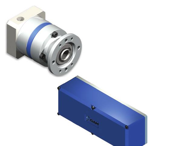
17 High Performance: EPL Series GAM can. If you don t see exactly what you need, let us know. We can modify the EPL Series gearboxes to meet your needs. Page 4 provides a list of coonly requested modifications to give you a feel for our capabilities. Our EPL Series is widely known as the best value on the market- tens of thousands of EPL s installed since 1998 in North America alone. That s because it offers the best quality available for the price point. We ve added some features that make it unequaled in its class and ideal for most servo applications. EPL Series enhancements include: A 50 frame size in our standard shaft version (-W) that is a drop-in for many gearboxes NEMA output version with oversized english shaft for improved performance Option for larger motor shafts New output configurations include: EPL-A dimensions that drop in for popular planetary gearboxes on the market. EPL-F that features a flange output for a compact design and allows for easy connecting of mechanical elements such as pulleys and pinions Adapter Plate (Customized adapter plates for quick and easy motor mounting) 2. Seals (Protective seals to isolate the gearbox) 7 3. Angular Contact Bearings (for high radial and axial loading) 4. Input Clamping Element 5. Planet Gears (Precision honed gears) 6. Ring Gear (Ring gear incorporated into housing) 7. Output Face 18 For more information, call us toll-free at 888-GAM-7117 Visit for 2-D and 3-D Drawings
 NEMA output face with oversized english shaft Ratios 3:1 to 1000:1")


18 EPL High Performance: EPL Series EPL-W GAM Metric Output Face Heavy Duty Output Bearings Ratios 3:1 to 1000:1 Frame sizes from 50 to 150 Ready to mount to your motor EPL-X (NEMA) NEMA output face with oversized english shaft Ratios 3:1 to 1000:1 Frame sizes from NEMA 17 to 56 Ready to mount to your motor EPL-A Metric output dimensions match many other popular inline planetary gear reducers on the market. Ratios 3:1 to 1000:1 Frame sizes from 50 to 155 Ready to mount to your motor EPL-F Flange output Compact design Ratios 3:1 to 1000:1 Ready to mount to your motor EPL-H Linear Mount Hollow output with zero backlash clamping ring A quick, simple, low cost solution used to mount onto any off the shelf linear belt or ball screw module. Ready to mount to your motor on the input Ready to mount to your module on the output For more information on Linear Mounts, refer to page 77. For more information, call us toll-free at 888-GAM-7117 Visit for 2-D and 3-D Drawings 19
19 EPL Series - EPL-W Nominal Output Torque (T 2n ) Max Acceleration Output Torque (T 2B ) Emergency Output Torque (T 2not ) EPL Series Stock Ratios 3, 5, 7, 10, 25, 50, 100 (Standard Input) N/A All Ratios Available Nm (lb-in) Nm (lb-in) Nm (lb-in) 1-stage: 3, 4, 5, 7, 10 2-stage: 12, 16, 20, 25, 35, 40, 50, 70, stage: 120, 160, 200, 250, 350, 490, 700, 1000 (Consult GAM for other ratios) 3:1 5 (44) 20 (177) 40 (354) 100 (885) 230 (2036) 4, 5, 7:1 6.5 (58) 26 (230) 54 (478) 120 (1062) 310 (2744) 10, 100, 1000:1 5 (44) 16 (142) 40 (354) 105 (929) 180 (1593) 12:1 14 (124) 36 (319) 80 (708) 170 (1505) 272 (2407) all other ratios 16 (142) 42 (372) 100 (885) 210 (1859) 340 (3009) 3:1 10 (89) 36 (319) 70 (620) 180 (1593) 360 (3186) 4, 5, 7:1 13 (115) 44 (389) 100 (885) 200 (1770) 460 (4071) 10, 100, 1000:1 10 (89) 24 (212) 75 (664) 180 (1593) 340 (3009) 12: (155) 45 (398) 100 (885) 215 (1903) 360 (3186) all other ratios 20 (177) 52 (460) 125 (1106) 255 (2257) 460 (4071) 3:1 20 (177) 72 (637) 160 (1416) 200 (1770) 860 (7612) 4, 5, 7:1 26 (230) 84 (743) 216 (1912) 480 (4248) 1000 (8851) 10, 100, 1000:1 20 (177) 62 (549) 160 (1416) 410 (3629) 800 (7081) 12:1 28 (248) 72 (637) 160 (1416) 400 (3540) 860 (7612) all other ratios 32 (283) 84 (743) 216 (1912) 480 (4248) 1000 (8851) Nominal Speed (n1n) RPM Max Speed (n 1max ) Standard Output Backlash (j) Allowable Radial Load (F rad ) 1 Allowable Axial Load (F axial ) Torsional Stiffness (C t21 ) Weight (m) arcmin 1-stage <16 < 10 < 10 < 8 < 8 2-stage <20 < 14 < 14 < 12 < 12 3-stage - < 18 < 18 < 16 < 16 N (lbs) (146) 1900 (428) 2800 (630) 5000 (1125) 7500 (1688) N (lbs) (158) 1500 (338) 2500 (563) 4500 (1013) 6000 (1350) Nm/arcmin (lb-in/ arcmin) kg (lbs) 10,100, (5.3) 1.3 (11.5) 3.4 (30.1) 8.3 (73.5) 22 (194.7) 7,70, (6.9) 1.7 (15) 4.8 (42.5) 13.6 (120.4) 27 (239) all other ratios 0.90 (8.0) 2.4 (21.2) 7.1 (62.8) 17.2 (152.2) 33 (292.1) 1-stage 0.4 (0.9) 1.0 (2.2) 2.3 (5.1) 5.8 (12.8) 10.0 (22.1) 2-stage 0.5 (1.1) 1.3 (2.9) 3.1 (6.8) 7.9 (17.4) 12.5 (27.6) 3-stage (3.5) 3.9 (8.6) 10.0 (22.1) 15.0 (33.1) Noise Level (L PA ) db(a) - < 64 < 66 < 68 < 70 < 72 Mass Moment of Inertia (J 1 ) kg cm 2 (lb-in 2 ) 3: (0.021) 0.45 (0.154) 1.37 (0.468) 6.54 (2.235) (4.179) 4:1, 12:1, 16: (0.014) 0.38 (0.130) 1.14 (0.390) 4.8 (1.640) 7.65 (2.614) 5:1, 20:1, 25: (0.014) 0.36 (0.123) 1.05 (0.359) 4.05 (1.384) 6.24 (2.132) 7:1, 35: (0.014) 0.35 (0.120) 0.97 (0.331) 3.4 (1.162) 4.7 (1.606) 10:1, 40:1-100: (0.014) 0.34 (0.116) 0.93 (0.318) 3.1 (1.059) 3.8 (1.299) 120:1-1000:1 (0.000) 0.34 (0.116) 0.93 (0.318) 3.12 (1.066) 3.9 (1.333) Efficiency at Load 1-stage: 94% 2-stage: 92% 3-stage: 90% Service Life Lubrication > 30,000 hours Mineral Grease EP0 Protection Rating IP 64 Operating Temperature Range -20 C to 90 C 1) Load applied at center of output RPM 20 For more information, call us toll-free at 888-GAM-7117 Visit for 2-D and 3-D Drawings
20 L2 EPL-W f2 L6 L3 D4 D1 D2k6 D3h7 D5 L7 L4 L1 L5 f1 L8 EPL-W Series (in) (in) (in) (in) (in) D1 max standard * motor shaft diameter 11 (0.433) 14 (0.551) 19 (0.748) 24 (0.945) 28 (1.102) D1 max available * motor shaft diameter 14 (0.551) 16 (0.63) 24 (0.945) 32 (1.26) 38 (1.496) D2 k6 output shaft diameter 12 (0.472) 14 (0.551) 20 (0.787) 25 (0.984) 40 (1.575) D3 h7 pilot diameter 35 (1.378) 40 (1.575) 55 (2.165) 80 (3.15) 110 (4.331) D4 bolt circle 44 (1.732) 52 (2.047) 70 (2.756) 100 (3.937) 130 (5.118) D5 housing diameter 50 (1.969) 64 (2.52) 84 (3.307) 118 (4.646) 150 (5.906) f1 shaft thread M4x8 M5x12 M6x16 M10x22 M10 x 22 f2 mounting holes M4x6 M5x12 M6x14 M8x18 M10x20 L1 1-STAGE** 93 (3.661) 117 (4.606) 162 (6.378) 199 (7.835) 265 (10.433) L1 2-STAGE** gearbox total length 109 (4.291) 139 (5.472) 195 (7.677) 239 (9.409) 305 (12.008) L1 3-STAGE** (6.339) 228 (8.976) 280 (11.024) 346 (13.622) L2 shaft length 24.5 (0.965) 39 (1.535) 54 (2.126) 61 (2.402) 81 (3.189) L3 key length 16 (0.63) 25 (0.984) 36 (1.417) 45 (1.772) 60 (2.362) L4 usable shaft length 18 (0.709) 30 (1.181) 45 (1.772) 50 (1.969) 70 (2.756) L5 pilot height 4 (0.157) 8 (0.315) 8 (0.315) 10 (0.394) 10 (0.394) L6 key width 4 (0.157) 5 (0.197) 6 (0.236) 8 (0.315) 12 (0.472) L7 key height 13.5 (0.531) 16 (0.63) 22.5 (0.886) 28 (1.102) 43 (1.693) L8** adapter size 50 (1.969) 70 (2.756) 90 (3.543) 120 (4.724) 150 (5.906) * for larger motor shaft diameters, please contact GAM ** depending on the motor, value can vary EPL Recoended Output Coupling (if necessary) metal bellows KLC-25 KLC-50 KLC-125 KM-270 KM-400 elastomer EKM-45 EKM-60 EKM-150 EKM-300 EKM-400 TYPE CODES FOR EPL SERIES (EPL-W) Example: EPL - W G - [115 - A01] - S111 Gearbox Series EPL w/ Metric Output Gearbox Style W = Output Shaft Gearbox Size 050, 064, 084, 118, 150 Ratio 3, 4, 5, 7, 10, 12, 16, 20, 25, 35, 40, 50, 70, 100, 120, 160, 200, 250, 350, 490, 700, 000=1000 Special Options Assigned by GAM Motor Mount Kit Assigned by GAM Options Available for This Product G = Key on output shaft per DIN6885 Tolerances () Size k6 h7 Over Thru Over Thru Over Thru Over Thru Over Thru
21 EPL Series - EPL-X (NEMA) 22 Nominal Output Torque (T 2n ) Max Accel. Torque (T 2B ) Emergency Output Torque (T 2not ) NEMA-X Series Stock Ratios N/A 3, 5, 7, 10, 25, 50, 100 N/A N/A All Ratios Available Nm (lb-in) Nm (lb-in) Nm (lb-in) 1-stage: 3, 4, 5, 7, 10 2-stage: 12, 16, 20, 25, 35, 40, 50, 70, stage: 120, 160, 200, 250, 350, 490, 700, :1 5 (44) 20 (177) 40 (354) 100 (885) 100 (885) 4, 5, 7:1 6.5 (58) 26 (230) 54 (478) 120 (1062) 120 (1062) 10, 100, 1000:1 5 (44) 16 (142) 40 (354) 105 (929) 105 (929) 12:1 14 (124) 36 (319) 80 (708) 170 (1505) 170 (1505) all other ratios 16 (142) 42 (372) 100 (885) 210 (1859) 210 (1859) 3:1 10 (89) 36 (319) 70 (620) 180 (1593) 180 (1593) 4, 5, 7:1 13 (115) 44 (389) 100 (885) 200 (1770) 200 (1770) 10, 100, 1000:1 10 (89) 24 (212) 75 (664) 180 (1593) 180 (1593) 12: (155) 45 (398) 100 (885) 215 (1903) 215 (1903) all other ratios 20 (177) 52 (460) 125 (1106) 255 (2257) 255 (2257) 3:1 20 (177) 72 (637) 160 (1416) 200 (1770) 200 (1770) 4, 5, 7:1 26 (230) 84 (743) 216 (1912) 480 (4248) 480 (4248) 10, 100, 1000:1 20 (177) 62 (549) 160 (1416) 410 (3629) 410 (3629) 12:1 28 (248) 72 (637) 160 (1416) 400 (3540) 400 (3540) all other ratios 32 (283) 84 (743) 216 (1912) 480 (4248) 480 (4248) Nominal Speed (n 1n ) RPM Max Input Speed (n 1max ) Standard Output Backlash (j) arcmin 1-stage < 20 < 10 < 10 < 8 < 8 2-stage < 24 < 14 < 14 < 12 < 12 3-stage < 30 < 18 < 18 < 16 < 16 Allowable Radial Load (F rad ) 1) N (lbs) (84) 450 (101) 900 (203) 2175 (489) 2175 (489) Allowable Axial Load (F axial ) Torsional Stiffness (C t21 ) Weight (m) N (lbs) (68) 420 (95) 650 (146) 1375 (309) 1375 (309) Nm/arcmin (lb-in/ arcmin) kg (lbs) 10,100,1000 Contact GAM 1.3 (11.5) 3.4 (30.1) 8.3 (73.5) 8.3 (73.5) 7,70,700 Contact GAM 1.7 (15) 4.8 (42.5) 13.6 (120.4) 13.6 (120.4) all other ratios Contact GAM 2.4 (21.2) 7.1 (62.8) 17.2 (152.2) 17.2 (152.2) 1-stage 0.4 (0.88) 1.0 (2.2) 2.3 (5.1) 5.8 (12.8) 5.8 (12.8) 2-stage 0.5 (1.1) 1.3 (2.9) 3.1 (6.8) 7.9 (17.4) 7.9 (17.4) 3-stage 0.6 (1.32) 1.6 (3.5) 3.9 (8.6) 10.0 (22.1) 10.0 (22.1) Noise Level (L PA ) db(a) - < 60 < 66 < 68 < 70 < 70 Mass Moment of Inertia (J 1 ) kg cm 2 (lb-in 2 ) 3: (0.005) 0.45 (0.154) 1.37 (0.468) 6.54 (2.235) 6.54 (2.235) 4:1, 12:1, 16: (0.003) 0.38 (0.130) 1.14 (0.390) 4.8 (1.640) 4.8 (1.640) 5:1, 20:1, 25: (0.003) 0.36 (0.123) 1.05 (0.359) 4.05 (1.384) 4.05 (1.384) 7:1, 35: (0.005) 0.35 (0.120) 0.97 (0.331) 3.4 (1.162) 3.4 (1.162) 10:1, 40:1-100: (0.003) 0.34 (0.116) 0.93 (0.318) 3.1 (1.059) 3.1 (1.059) 120:1-1000: (0.003) 0.34 (0.116) 0.93 (0.318) 3.12 (1.066) 3.12 (1.066) Efficiency at Load 1-stage: 94% 2-stage: 92% 3-stage: 90% Service Life Lubrication > 30,000 hours Mineral Grease EP0 Protection Rating IP 64 Operating Temperature Range -20 C to 90 C 1) Load applied at center of output RPM For more information, call us toll-free at 888-GAM-7117 Visit for 2-D and 3-D Drawings
 D1 max available * motor shaft diameter - (-) 16 (0.63) 24 (0.945) 32 (1.26) 32 (1.26) D2 k6 output shaft diameter 9.525 (0.375) 12.7 (0.5) 19.050 (0.75) 25 (0.984) 25 (0.")
22 L4 EPL-X L6 L3 D5 D2 k6 D1 D3 h7 L7 ØD4 L5 L2 L1 L8 NEMA-X Series (in) (in) (in) (in) (in) D1 max standard * motor shaft diameter 11 (0.433) 14 (0.551) 19 (0.748) 24 (0.945) 24 (0.945) D1 max available * motor shaft diameter - (-) 16 (0.63) 24 (0.945) 32 (1.26) 32 (1.26) D2 k6 output shaft diameter (0.375) 12.7 (0.5) (0.75) 25 (0.984) 25 (0.984) D3 h7 pilot diameter (0.865) 38.1 (1.5) 73 (2.874) (2.187) (4.50) D4 bolt circle 43.8 (1.724) 66.7 (2.626) (3.874) (4.949) (7.000) D5 mounting holes 3.25 (0.128) 5 (0.197) 5.5 (0.217) 7.1 (0.28) (0.402) L1 1-STAGE** 108 (4.252) 111 (4.37) 147 (5.787) 199 (7.835) 199 (7.835) L1 2-STAGE** gearbox total length 124 (4.882) 133 (5.236) 180 (7.087) 239 (9.409) 239 (9.409) L1 3-STAGE** (5.492) 155 (6.102) 213 (8.386) 280 (11.024) 280 (11.024) L2 shaft length 25.4 (1.000) 25.4 (1.000) 31.8 (1.252) 42 (1.654) 41 (1.614) L3 key length - (-) (0.75) 25.4 (1) 38 (1.496) 32 (1.26) L4 pilot height 1.6 (0.063) 1.6 (0.063) 1.7 (0.067) 2.4 (0.094) 4 (0.157) L5 flange thickness 4.9 (0.193) 5 (0.197) 10 (0.394) 19 (0.748) 20 (0.7874) L6 key width - (-) (0.125) 4.78 (0.188) 8 (0.315) 8 (0.315) L7 key height / flat height 9.14 (0.36) (0.56) (0.838) 28 (1.102) 28 (1.102) L8 flange size 40 (1.575) 65 (2.559) 90 (3.543) 120 (4.724) 145 (5.709) * for larger motor shaft diameters, please contact GAM **depending on the motor, value can vary *** long motor shafts can be accoodated, but overall gearbox length will grow EPL Recoended Output Coupling (if necessary) metal bellows KLC-25 KLC-50 KLC-125 KM-270 KM-400 elastomer EKM-20 EKM-60 EKM-150 EKM-300 EKM-400 TYPE CODES FOR EPL SERIES (EPL-X (NEMA)) Example: EPL - X G - [115 - A01] - S111 Gearbox Series EPL w/ NEMA output Gearbox Style X17 = NEMA17 X23 = NEMA23 X34 = NEMA34 X42 = NEMA42 X56 = NEMA56 Ratio 3, 4, 5, 7, 10, 12, 16, 20, 25, 35, 40, 50, 70, 100, 120, 160, 200, 250, 350, 490, 700, 000=1000 Special Options Assigned by GAM Motor Mount Kit Assigned by GAM Options Available for This Product G = Key on output shaft per DIN6885 Tolerances () Size k6 h7 Over Thru Over Thru Over Thru Over Thru Over Thru
23 EPL Series - EPL-A Nominal Output Torque (T 2n ) Max Acceleration Output Torque (T 2B ) Emergency Output Torque (T 2not ) EPL-A Series All Ratios Available Nm (lb-in) Nm (lb-in) Nm (lb-in) 1stage: 3, 4, 5, 7, 10 2stage: 12,16, 20, 25, 35, 40, 50, 70, 100 3stage: 120, 160, 200, 250, 350, 490, 700, 1000 (Consult GAM for other ratios) 3:1 5 (44) 20 (177) 40 (354) 100 (885) 230 (2036) 4, 5, 7:1 6.5 (58) 26 (230) 54 (478) 120 (1062) 310 (2744) 10, 100, 1000:1 5 (44) 16 (142) 40 (354) 105 (929) 180 (1593) 12:1 14 (124) 36 (319) 80 (708) 170 (1505) 272 (2407) all other ratios 16 (142) 42 (372) 100 (885) 210 (1859) 340 (3009) 3:1 10 (89) 36 (319) 70 (620) 180 (1593) 360 (3186) 4, 5, 7:1 13 (115) 44 (389) 100 (885) 200 (1770) 460 (4071) 10, 100, 1000:1 10 (89) 24 (212) 75 (664) 180 (1593) 340 (3009) 12: (155) 45 (398) 100 (885) 215 (1903) 360 (3186) all other ratios 20 ( (460) 125 (1106) 255 (2257) 460 (4071) 3:1 20 (177) 72 (637) 160 (1416) 200 (1770) 860 (7612) 4, 5, 7:1 26 ( (743) 216 (1912) 480 (4248) 1000 (8851) 10, 100, 1000:1 20 (177) 62 (549) 160 (1416) 410 (3629) 800 (7081) 12:1 28 (248) 72 (637) 160 (1416) 400 (3540) 860 (7612) all other ratios 32 (283) 84 (743) 216 (1912) 480 (4248) 1000 (8851) Nominal Speed (n1n) RPM Max Speed (n 1max ) RPM Standard Output Backlash (j) Allowable Radial Load (F rad ) 1 Allowable Axial Load (F axial ) Torsional Stiffness (C t21 ) Weight (m) arcmin 1stage <16 < 10 < 10 < 8 < 8 2stage <20 < 14 < 14 < 12 < 12 3stage - < 18 < 18 < 16 < 16 N (lbs) (146) 1550 (348) 2400 (540) 4600 (1034) 7500 (1686) N (lbs) (158) 1450 (326) 1900 (427) 4000 (899) 6000 (1349) Nm/arcmin (lbin/arcmin) kg (lbs) 10,100, (5.3) 1.3 (11.5) 3.4 (30.1) 8.3 (73.5) 22 (194.7) 7,70, (6.9) 1.7 (15) 4.8 (42.5) 13.6 (120.4) 27 (239) all other ratios 0.90 (8.0) 2.4 (21.2) 7.1 (62.8) 17.2 (152.2) 33 (292.1) 1stage 0.4 (0.9) 1 (2.2) 2.3 (5.1) 5.8 (12.8) 10 (22.1) 2stage 0.5 (1.1) 1.3 (2.9) 3.1 (6.8) 7.9 (17.4) 12.5 (27.6) 3stage (3.5) 3.9 (8.6) 10.0 (22.1) 15 (33.1) Noise Level (L PA ) db(a) - < 64 <66 <68 <70 <72 Mass Moment of Inertia (J 1 ) kg cm 2 (lb-in 2 ) 3: (0.021) 0.45 (0.154) 1.37 (0.468) 6.54 (2.235) (4.179) 4:1, 12:1, 16: (0.014) 0.38 (0.13) 1.14 (0.390) 4.8 (1.640) 7.65 (2.614) 5:1, 20:1, 25: (0.014) 0.36 (0.123) 1.05 (0.359) 4.05 (1.384) 6.24 (2.132) 7:1, 35: (0.014) 0.35 (0.12) 0.97 (0.331) 3.4 (1.162) 4.7 (1.606) 10:1, 40:1-100: (0.014) 0.34 (0.116) 0.93 (0.318) 3.1 (1.059) 3.8 (1.299) 120:1-1000: (0.116) 0.93 (0.318) 3.12 (1.066) 3.9 (1.333) Efficiency at Load 1stage: 94% 2stage: 92% 3stage: 90% Service Life Lubrication > 30,000 hours Mineral Grease EP0 Protection Rating IP 64 Operating Temperature Range -20 C to 90 C 24 For more information, call us toll-free at 888-GAM-7117 Visit for 2-D and 3-D Drawings
24 L2 EPL-A f2 L3 D4 L6 D1 D2k6 D3h6 D5 L7 L4 L1 L5 f1 L8 EPL-A Series (in) (in) (in) (in) (in) D1 max standard * motor shaft diameter 11 (0.433) 14 (0.551) 19 (0.748) 24 (0.945) 28 (1.102) D1 max available* motor shaft diameter 14 (0.551) 16 (0.630) 24 (0.945) 32 (1.260) 38 (1.496) D2 k6 output shaft diameter 12 (0.472) 16 (0.630) 22 (0.866) 32 (1.260) 40 (1.575) D3h6 pilot diameter 35 (1.378) 52 (2.047) 68 (2.677) 90 (3.543) 120 (4.724) D4 Bolt Circle 44 (1.732) 62 (2.441) 80 (3.150) 108 (4.252) 140 (5.512) D5 Housing Diameter 50 (1.968) 70 (2.756) 90 (3.543) 118 (4.646) 155 (6.102) f1 Shaft Thread M4x8 M5x17 M8x25 M12x37 M16x45 f2 Mounting Holes (8x) M4x6 (8x) M5x12 (8x) M6x14 (8x) M8x18 (8x) M10x24 L1 1-STAGE** 93 (3.661) 130 (5.118) 164 (6.457) 222 (8.740) 300 (11.811) L1 2-STAGE** gearbox total length 109 (4.291) 152 (5.984) 196 (7.717) 263 (10.354) 341 (13.425) L1 3-STAGE** (6.850) 229 (9.016) 304 (11.968) 382 (15.039) L2 Shaft length 24.5 (0.965) 36 (1.417) 46 (1.811) 70 (2.756) 94 (3.701) L3 Key Length 16 (0.630) 25 (0.984) 30 (1.181) 50 (1.968) 70 (2.756) L4 Useable Shaft Length 18 (0.709) 28 (1.102) 35 (1.378) 58 (2.283) 82 (3.228) L5 Pilot Height 4 (0.157) 5.5 (0.217) 9 (0.354) 7 (0.276) 5.5 (0.217) L6 Key Width 4 (0.157) 5 (0.197) 6 (0.236) 10 (0.394) 12 (0.472) L7 Key Height 13.5 (0.531) 18 (0.709) 24.5 (0.965) 35 (1.378) 43 (1.693) L8** Adapter Size 50 (1.968) 70 (2.756) 90 (3.543) 120 (4.724) 150 (5.905) * for larger motor shaft diameters, please contact GAM **depending on the motor, value can vary *** longer motor shafts can be accoodated, but overall gearbox length will grow EPL Recoended Output Coupling (if necessary) metal bellows KLC-25 KLC-50 KLC-125 KM-270 KM-400 elastomer EKM-20 EKM-60 EKM-150 EKM-300 EKM-400 TYPE CODES FOR EPL SERIES (EPL-A) Example: EPL - A G - [115 - A01] - S111 Gearbox Series EPL w/ Popular Metric Output Dimensions Gearbox Style A= Output Shaft Gearbox Size 050, 070, 090, 120, 155 Ratio 3, 4, 5, 7, 10, 12, 16, 20, 25, 35, 40, 50, 70, 100, 120, 160, 200, 250, 350, 490, 700, 000=1000 Special Options Assigned by GAM Motor Mount Kit Assigned by GAM Options Available for This Product G = Key on output shaft per DIN6885 Tolerances () Size k6 h6 Over Thru Over Thru Over Thru Over Thru Over Thru
25 EPL Series - EPL-F Nominal Output Torque (T 2n ) Max Acceleration Output Torque (T 2B ) Emergency Output Torque (T 2not ) EPL-F Series All Ratios Available Nm (lb-in) Nm (lb-in) Nm (lb-in) 1-Stage: 3, 4, 5, 7, 10 2-Stage: 12, 16, 20, 25, 35, 40, 50, 70, Stage: 120, 160, 200, 250, 350, 490, 700, :1 20 (177) 40 (354) 100 (885) 4, 5, 7:1 26 (230) 54 (478) 120 (1062) 10, 100, 1000:1 16 (142) 40 (354) 105 (929) 12:1 36 (319) 80 (708) 170 (1505) all other ratios 42 (372) 100 (885) 210 (1859) 3:1 36 (319) 70 (620) 180 (1593) 4, 5, 7:1 44 (389) 100 (885) 200 (1770) 10, 100, 1000:1 24 (212) 75 (664) 180 (1593) 12:1 45 (398) 100 (885) 215 (1903) all other ratios 52 (460) 125 (1106) 255 (2257) 3:1 72 (637) 160 (1416) 200 (1770) 4, 5, 7:1 84 (743) 216 (1912) 480 (4248) 10, 100, 1000:1 62 (549) 160 (1416) 410 (3629) 12:1 72 (637) 160 (1416) 400 (3540) all other ratios 84 (743) 216 (1912) 480 (4248) Nominal Speed (n1n) RPM Max Speed (n 1max ) RPM Standard Output Backlash (j) arcmin 1stage < 10 < 10 < 8 2stage < 14 < 14 < 12 3stage < 18 < 18 < 16 Allowable Radial Load (F rad ) 1 N (lbs) (270) 2000 (450) 2100 (472) Allowable Axial Load (F axial ) N (lbs) (180) 1000 (225) 1400 (315) Torsional Stiffness (C t21 ) Weight (m) Nm/arcmin (lbin/arc-min) kg (lbs) 10,100, (11.5) 3.4 (30.1) 8.3 (73.5) 7,70, (15) 4.8 (42.5) 13.6 (120.4) all other ratios 2.4 (21.2) 7.1 (62.8) 17.2 (152.2) 1stage 1 (2.2) 2.3 (5.1) 5.8 (12.8) 2stage 1.3 (2.9) 3.1 (6.8) 7.9 (17.4) 3stage 3.5 (3.9) 3.9 (8.6) 10.0 (22.1) Noise Level (L PA ) db(a) - <66 <68 <70 Mass Moment of Inertia (J 1 ) kg cm 2 (lb-in 2 ) 3: (0.208) 1.79 (0.612) 8.53 (2.915) 4:1, 12:1, 16:1 0.5 (0.171) 1.47 (0.502) 6.11 (2.088) 5:1, 20:1, 25: (0.164) 1.23 (0.420) 4.87 (1.664) 7:1, 35: (0.133) 1.14 (0.390) 3.71 (1.268) 10:1, 40:1-100: (0.130) 1.1 (0.376) 3.38 (1.155) 120:1-1000: (0.130) 1.1 (0.376) 3.39 (1.158) Efficiency at Load 1stage: 94% 2stage: 92% 3stage: 90% Service Life Lubrication > 30,000 hours Mineral Grease EP0 Protection Rating IP 64 Operating Temperature Range -20 C to 90 C 26 For more information, call us toll-free at 888-GAM-7117 Visit for 2-D and 3-D Drawings
26 L5 L4 L6 EPL-F D9 (8x) D11 H7 D8 D1 D10 H7 D2 h7 D4 h7 D5 L2 D7 f1 L1 L3 EPL-F Series (in) (in) (in) D1 max standard * motor shaft diameter 14 (0.551) 19 (0.748) 24 (0.945) D1 max available * motor shaft diameter 16 (0.630) 24 (0.945) 32 (1.260) D2 h7 output flange diameter 40 (1.575) 63 (2.480) 80 (3.150) D4 h7 pilot diameter 64 (2.520) 90 (3.543) 110 (4.331) D5 flange diameter 86 (3.386) 118 (4.646) 145 (5.709) D7 inner bolt circle 31.5 (1.240) 50 (1.968) 63 (2.480) D8 outer bolt circle 79 (3.110) 109 (4.291) 135 (5.315) D9 mounting hole diameter (8x) 4.5 (0.177) 5.5 (0.217) 5.5 (0.217) D10 H7 flange pilot 20 (0.787) 31.5 (1.240) 40 (1.575) D11 H7 dowel diameter 5 (0.197) 6 (0.236) 6 (0.236) f1 flange tap (7) M5x7 (7) M6x10 (7) M6x12 L1 1-STAGE** 93 (3.661) 126 (4.961) 150 (5.905) L1 2-STAGE** gearbox total length 113 (4.490) 158 (6.220) 190 (7.480) L1 3-STAGE** 129 (5.08) 191 (7.520) 231 (9.094) L2 flange pilot depth 4 (0.157) 6 (0.236) 6 (0.236) L3 pilot height 7 (0.276) 10 (0.394) 10 (0.394) L4 output length 19.5 (0.768) 30 (1.181) 29 (1.142) L5 flange thickness 4 (0.157) 7 (0.276) 8 (0.315) L6 output flange length 3 (0.118) 6 (0.236) 6 (0.236) EPL * for larger motor shaft diameters, please contact GAM ** depending on the motor, value can vary TYPE CODES FOR EPL SERIES (EPL-F) Example: EPL - F H - [115 - A01] - S111 Gearbox Series EPL w/ Flange Output Gearbox Style F = Flange Output Shaft Gearbox Size 064, 090, 110 Ratio 3, 4, 5, 7, 10, 12, 16, 20, 25, 35, 40, 50, 70, 100, 120, 160, 200, 250, 350, 490, 700, 000=1000 Special Options Assigned by GAM Motor Mount Kit Assigned by GAM Options Available for This Product H= No Keyways Tolerances () Size h7 H7 Over Thru Over Thru Over Thru Over Thru Over Thru
27 EPL Series: EPL-H EPL Series Stock Ratios 3, 5, 7, 10, 25, 50, 100 (Standard Input) All Ratios Available 1-stage: 3, 4, 5, 7, 10 2-stage: 12, 16, 20, 25, 35, 40, 50, 70, stage: 120, 160, 200, 250, 350, 490, 700, :1, 10:1, 100:1, 1000:1 14 (124) 40 (354) 100 (885) Nominal Output Torque (T 2n ) Nm (lb-in) 4:1, 5:1, 7:1 26 (230) 50 (443) 120 (1062) all other ratios 36 (319) 64 (566) 165 (1460) 3:1, 10:1, 100:1, 1000:1 25 (221) 60 (531) 150 (1328) Max Accel Output Torque (T 2B ) Nm (lb-in) 4:1, 5:1, 7:1 40 (354) 75 (664) 180 (1593) all other ratios 44 (389) 75 (664) 180 (1593) Nominal Input Speed (n 1n ) RPM Max Input Speed (n 1max ) RPM :1-10:1 < 10 < 10 < 8 Standard Output Backlash (j) arcmin 12:1-100:1 < 14 < 14 < :1-1000:1 < 18 < 18 < 16 1-stage 1.0 (2.2) 2.3 (5.1) 5.8 (12.8) Weight (m) kg (lb) 2-stage 1.3 (2.9) 3.1 (6.8) 7.9 (17.4) 3-stage 1.6 (3.5) 3.9 (8.6) 10.0 (22.1) Noise Level (L PA ) db (A) - < 66 < 68 < 70 3: (0.154) 1.37 (0.468) 6.54 (2.235) 4:1, 12:1, 16: (0.130) 1.14 (0.390) 4.8 (1.640) Mass Moment of Inertia (J 1 ) kg cm 2 (lb-in 2 ) 5:1, 20:1, 25: (0.123) 1.05 (0.359) 4.05 (1.384) 7:1, 35: (0.120) 0.97 (0.331) 3.4 (1.162) 10:1, 40:1-100: (0.116) 0.93 (0.318) 3.1 (1.059) 120:1-1000: (0.116) 0.93 (0.318) 3.12 (1.066) Efficiency at Load 1-stage: 92% 2-stage: 90% 3-stage: 88% Service Life > 20,000 hours Lubrication Mineral Grease EP0 Protection Rating IP 64 Operating Temperature Range -20 C to 90 C 28 For more information, call us toll-free at 888-GAM-7117 Visit for 2-D and 3-D Drawings
28 EPL EPL Series (in) (in) (in) D1 max standard* motor shaft diameter 14 (0.551) 19 (0.748) 24 (0.945) D1 max available* motor shaft diameter 16 (0.63) 24 (0.945) 32 (1.26) D2 max output shaft diameter 16 (0.63) 20 (0.787) 30 (1.181) D3 H7 pilot diameter 44 (1.732) 60 (2.362) 80 (3.15) D4 bolt circle 55.5 (2.185) 73 (2.874) 105 (4.134) D5 flange diameter 70 (2.756) 84 (3.307) 118 (4.646) D6 mounting holes 5.5 (0.217) 5.5 (0.217) 6.6 (0.26) L1 1-STAGE** 98.5 (3.878) 122 (4.803) (6.122) L1 2-STAGE** gearbox total length (4.744) 155 (6.102) 196 (7.717) L1 3-STAGE** (5.61) 188 (7.402) (9.311) L2 pilot depth 3.5 (0.138) 3.5 (0.138) 3.5 (0.138) L3 flange size 70 (2.756) 90 (3.543) 120 (4.724) L4 allowable shaft depth 28 (1.102) 30 (1.181) 27 (1.063) L5 flange thickness 6 (0.236) 6 (0.236) 10 (0.394) W1 bolt hole spacing 125 4x 90 4x 90 W2 hole angle W3 hole angle * for larger motor shaft diameters, please contact GAM ** depending on the motor, value can vary TYPE CODES FOR EPL SERIES (EPL-H) Example: EPL - H H - [115 - A01] - S111 Gearbox Series EPL w/ Linear Mount Output Gearbox Style H = Hollow Output Shaft Gearbox Size 064, 084, 118 Ratio 3, 4, 5, 7, 10, 12, 16, 20, 25, 35, 40, 50, 70, 100, 120, 160, 200, 250, 350, 490, 700, 000 = 1000 Special Options Assigned by GAM Motor Mount Kit Assigned by GAM Options Available for This Product H = No Keyways Tolerances () Size H7 Over Thru 10 0 Over Thru 18 0 Over Thru 30 0 Over Thru 50 0 Over Thru

29 High Performance: SSP Series GAM can. If you don t see exactly what you need, let us know. We can modify the SSP Series gearboxes to meet your needs. Page 4 provides a list of coonly requested modifications to give you a feel for our capabilities. Our Stainless Steel Planetery (SSP) Series is an innovative washdown servo gearbox solution designed for food, medical or sanitary applications. It is a precision planetary gearbox outwardly constructed of 300-series stainless steel. The motor adapter plate, housing and shaft are all stainless steel. Viton seals, stainless steel hardware and sealed interfaces provide outstanding corrosion resistance in all types of wet and caustic washdown environments. Ideal for any light or demanding servo application where corrosion resistance is a requirement, the SSP Series offers economy, high precision, and long lasting performance. SSP Series benefits: All exposed surfaces stainless steel Frame sizes from 70 to 120 Ratios from 3:1 to 100: Suitable for food or medical applications! 1. Adapter Flange (Stainless steel adapter for quick and easy motor mounting) 2. Hole Plug (Threaded stainless steel plug) 3. Lubrication (internal) (Standard with food grade grease) 4. Seals (internal) (Viton seals keep contaminants out and lubricant in and achieves an IP66 rating) 5. Shaft (Stainless steel keyed output shaft) 30 For more information, call us toll-free at 888-GAM-7117 Visit for 2-D and 3-D Drawings


30 High Performance: SSP Series SSP-W Dual output bearings for high radial and axial loading Frame sizes from 70 to 120 Ratios from 3:1 to 100:1 SSP-W SSP SSP-W Input clamping element for fast and easy mounting Optional input O-ring to keep contaminants out custom designed for your motor. (Special request at time of order) SSP-W Rear View SSP-W Optional stainless steel output coupling KG-VA for corrosion resistant connections to other shafts Contact GAM for more information on these couplings SSP-W with Coupling For more information, call us toll-free at 888-GAM-7117 Visit for 2-D and 3-D Drawings 31
31 SSP-Series - SSP SSP Series Stock Ratios 5,10 All Ratios Available Nominal Output Torque (T 2n ) Max Acceleration Output Torque (T 2B ) Emergency Output Torque (T 2not ) Nm (lb-in) Nm (lb-in) Nm (lb-in) 1-stage: 3, 4, 5, 7, 10 2-stage: 12, 16, 20, 25, 35, 40, 50, 70, 100 For other ratios, consult GAM 3:1 20 (177) 40 (354) 100 (885) 4, 5, 7:1 26 (230) 54 (478) 120 (1062) 10, 100, 1000:1 16 (142) 40 (354) 105 (929) 12:1 36 (319) 80 (708) 170 (1505) all other ratios 42 (372) 100 (885) 210 (1859) 3:1 36 (319) 70 (620) 180 (1593) 4, 5, 7:1 44 (389) 100 (885) 200 (1770) 10, 100, 1000:1 24 (212) 75 (664) 180 (1593) 12:1 45 (398) 100 (885) 215 (1903) all other ratios 52 (460) 125 (1106) 255 (2257) 3:1 72 (637) 160 (1416) 200 (1770) 4, 5, 7:1 84 (743) 216 (1912) 480 (4248) 10, 100, 1000:1 62 (549) 160 (1416) 410 (3629) 12:1 72 (637) 160 (1416) 400 (3540) all other ratios 84 (743) 216 (1912) 480 (4248) Nominal Input Speed (n 1n ) RPM Max Speed (n 1max ) Standard Output Backlash (j) arcmin 3:1-10:1 < 10 < 10 < 8 12:1-100:1 < 14 < 14 < 12 Allowable Radial Load (F rad ) 1) N (lbs) (205) 1500 (338) 3000 (675) Allowable Axial Load (F axial ) N (lbs) (113) 1000 (225) 1500 (338) Torsional Stiffness (C t21 ) Nm/ arcmin (lb-in/ rcmin) Weight (m) kg (lbs) 10:1, 100:1 1.3 (11.5) 3.4 (30.1) 8.3 (73.5) 7:1, 70:1 1.7 (15) 4.8 (42.5) 13.6 (120.4) all other ratios 2.4 (21.2) 7.1 (62.8) 17.2 (152.2) 1-stage 2 (4.4) 3.9 (8.6) 8.8 (19.4) 2-stage 2.3 (5.1) 4.7 (10.4) 10.9 (24) Noise Level (L PA ) db(a) - < 64 < 66 < 68 Mass Moment of Inertia (J 1 ) kg cm 2 (lb-in 2 ) 3: (0.154) 1.37 (0.468) 6.54 (2.235) 4:1, 12:1, 16: (0.130) 1.14 (0.390) 4.8 (1.640) 5:1, 20:1, 25: (0.123) 1.05 (0.359) 4.05 (1.384) 7:1, 35: (0.120) 0.97 (0.331) 3.4 (1.162) 10:1, 40:1-100: (0.116) 0.93 (0.318) 3.1 (1.059) Efficiency at Load 1-stage: 94% 2-stage: 92% Service Life Lubrication > 30,000 hours Food Grade Grease: Note 1. Meets FDA 21 CFR requirements Note 2. USDA H1 authorized (authorized for use in federally inspected meat and poultry plants) Protection Rating IP 66 Operating Temperature Range -20 C to 90 C 1) Load applied at center of output RPM 32 For more information, call us toll-free at 888-GAM-7117 Visit for 2-D and 3-D Drawings
32 L2 SSP-W f2 L6 L3 D4 D1 D2k6 D3h7 D5 L7 L4 L5 f1 L1 L8 SSP Series (in) (in) (in) D1 max standard motor shaft diameter 14 (0.551) 19 (0.748) 24 (0.945) D1 max available* motor shaft diameter 16 (0.63) 24 (0.945) 32 (1.26) D2 k6 output shaft diameter 16 (0.63) 22 (0.866) 32 (1.26) D3 h7 pilot diameter 52 (2.047) 68 (2.677) 90 (3.543) D4 bolt circle 62 (2.441) 80 (3.15) 108 (4.252) D5 housing diameter 70 (2.756) 92 (3.622) 122 (4.803) f1 shaft thread M5x12 M6x16 M10x22 f2 mounting holes (4) M6x12 (4) M6x14 (8) M8x18 L1 1-STAGE*** 131 (5.157) 174 (6.85) 232 (9.134) gearbox total length L1 2-STAGE*** 153 (6.024) 207 (8.15) 271 (10.669) L2 shaft length 36 (1.417) 46 (1.811) 70 (2.756) L3 key length 25 (0.984) 30 (1.181) 50 (1.969) L4 usable shaft length 28 (1.102) 36 (1.417) 58 (2.283) L5 pilot height 7 (0.276) 9 (0.354) 11 (0.433) L6 key width 5 (0.197) 6 (0.236) 10 (0.394) L7 key height 18 (0.709) (0.969) 34.8 (1.37) * for these larger motor shaft diameters, please contact GAM ** depending on the motor, value can vary SSP Recoended Output Coupling (if necessary) all stainless bellows KG-VA-80 KG-VA-220 KG-VA-350 TYPE CODES FOR SSP SERIES (SSP-W) Example: SSP - W G - [115 - A01] - S111 Gearbox Series Stainless Steel Planetary Series Gearbox Style W = Output Shaft Gearbox Size 070, 090, 120 Ratio 3, 4, 5, 7, 10, 12, 16, 20, 25, 35, 40, 50, 70, 100 Special Options Assigned by GAM Motor Mount Kit Assigned by GAM Options Available for This Product G = Key on output DIN688 Tolerances () Size k6 h7 Over Thru Over Thru Over Thru Over Thru Over Thru

33 High Performance: FP Series GAM can. If you don t see exactly what you need, let us know. We can modify the FP Series gearboxes to meet your needs. Page 4 provides a list of coonly requested modifications to give you a feel for our capabilities. The FP Series is a shaftless planetary gearbox that offers advantages in space and performance. The output flange allows machine elements such as pinion gears, pulleys, rotary index tables, and transmission shafting to be easily connected directly to the output. The design also provides high torsional and tilting rigidity that improves machine performance. Features and Benefits of the FP Series include: Compact design High tilting rigidity for high overhung loads Best in class performance for accuracy due to High torsional stiffness Low backlash Lightweight Long design life of 20,000 hours Lubricated for life Ready for motor mounting Ratios 5:1-91:1 Frame sizes from 50 to Adapter Flange (Customized adapter flanges for quick and easy motor mounting) 2. Output Bearing (internal) (Innovative bearing arrangement for high stiffness) 3. Output Flange (Easily mount components directly to flange) 4. Flange Pilot (Centering pilot for machine elements) 5. Mounting Flange (Allows for compact machine mounting) 34 For more information, call us toll-free at 888-GAM-7117 Visit for 2-D and 3-D Drawings


 for high torsional stiffness and a zero")

34 High Performance: FP Series Shown with custom shaft easily bolted to gearbox Simplify machine system GAM can provide custom shafts with standard FP gearboxes Shafts can be easily added and removed with a few bolts when changes are required Shown with pinion gear bolted to the output face A true zero backlash connection of the pinion to the gearbox Ideal for compact, rigid systems FP Shown with pulley mounted to the output face FP-FB Bellows output Direct mount pulley to the flange face Ideal for indirect drives Integrated coupling on output (FP-FB) for high torsional stiffness and a zero backlash connection while compensating for misalignment Available with flange mounted bellows or elastomer couplings For more information, call us toll-free at 888-GAM-7117 Visit for 2-D and 3-D Drawings 35
35 FP Series - FP FP Series Stock Ratios 5, 10 All Ratios Available Nominal Output Torque (T 2n ) Max Acceleration Output Torque (T 2B ) Emergency Output Torque (T 2not ) Nm (lb-in) Nm (lb-in) Nm (lb-in) 5, 7, 10, 21, 31, 43, 61, 91 (91:1 ratio not available in size 50) 5:1, 7:1 6.5 (58) 26 (230) 54 (478) 120 (1062) 10:1, 91:1 5 (44) 16 (142) 40 (354) 105 (929) all other ratios 16 (142) 44 (389) 100 (885) 210 (1859) 5:1, 7:1 13 (115) 36 (319) 100 (885) 200 (1770) 10:1, 91:1 9 (80) 24 (212) 75 (664) 180 (1593) all other ratios 18 (159) 55 (487) 125 (1106) 255 (2257) 5:1, 7:1 26 (230) 84 (743) 216 (1912) 480 (4248) 10:1, 91:1 20 (177) 62 (549) 110 (974) 410 (3629) all other ratios 26 (230) 84 (743) 216 (1912) 480 (4248) Nominal Speed (n 1n ) RPM Max Speed (n 1max ) Standard Output Backlash (j) Reduced Output Backlash (j) Radial Load (F rad ) Axial Load (F axial ) Tilting Rigidity 1 Tilting Moment Load (M T )* Torsional Stiffness Weight (m) arcmin arcmin N (lbs) N (lbs) Nm/arcmin (lb-in/arcmin) Nm (lb-in) Nm/arcmin (lb-in/arcmin) kg (lbs) 1 Stage <12 < 8 < 8 < 8 2 Stage <15 <11 <11 <11 1 Stage <8 < 5 < 5 < 5 2 Stage <12 <8 <8 <8 100rpm 1333 (300) 1932 (434) 3972 (893) 6541 (1470) 200rpm 1131 (254) 1389 (312) 2540 (571) 3955 (889) 300rpm 848 (191) 1050 (236) 1837 (413) 2696 (606) 100rpm 359 (81) 445 (100) 795 (179) 1175 (264) 200rpm 243 (55) 293 (66) 508 (114) 709 (159) 300rpm 186 (42) 219 (49) 368 (83) 483 (109) - 11 (97) 19 (168) 51 (451) 127 (1124) 100rpm 33 (292) 57 (505) 147 (1301) 296 (2620) 200rpm 28 (248) 41 (363) 94 (832) 179 (1584) 300rpm 21 (186) 31 (274) 68 (602) 122 (1080) 5, (4.4) 2.4 (21.12) 7.1 (62.48) 17.2 (151.36) 7, 31, 43, (3.52) 2.2 (19.36) 6 (52.8) 14 (123.2) 10, (3.52) 2 (17.6) 5 (44) 10 (88) 1 Stage 0.8 (2) 1.5 (3) 3.5 (8) 7.6 (17) 2 Stage 1 (2.2) 1.8 (4) 3.8 (8.4) 8.4 (18.5) Noise Level (L PA ) db - < 64 < 66 < 68 < 70 Mass Moment of Inertia (J 1 ) kg cm 2 all ratios 1 Stage 2 Stage 1 Stage 2 Stage 1 Stage 2 Stage 1 Stage 2 Stage Efficiency at Load 1 stage efficiency: 94% 2 stage efficiency: 92% Service Life Lubrication >20,000 hours Lifetime lubricant with grease Protection Rating IP 65 Operating Temperature Range -10 C to 90 C *Maximum value without axial load 1) Radial load distance shown in dimension tables (L7) 36 For more information, call us toll-free at 888-GAM-7117 Visit for 2-D and 3-D Drawings
36 FP FP Series (in) (in) (in) (in) D1 max motor shaft diameter 14 (0.551) 14 (0.551) 22 (0.866) 28 (1.102) D1 max (2-Stage) motor shaft diameter 14 (0.551) 14 (0.551) 19 (0.748) 22 (0.866) D2 output flange diameter 42 (1.654) 55 (2.165) 75 (2.953) 105 (4.134) D4 h7 pilot diameter 57 (2.244) 72 (2.835) 100 (3.937) 130 (5.118) D5 flange diameter 69 (2.717) 84 (3.307) 118 (4.646) 150 (5.906) D6 input housing diameter 56 (2.205) 72 (2.835) 100 (3.937) 130 (5.118) D7 inner bolt circle 28 (1.102) 36 (1.417) 60 (2.362) 80 (3.150) D8 outer bolt circle 63 (2.480) 78 (3.071) 109 (4.291) 140 (5.512) D9 mounting holes 3.5 (0.138) 3.5 (0.138) 4.5 (0.177) 5.5 (0.217) D10 H7 flange pilot 12 (0.472) 19 (0.748) 28 (1.102) 40 (1.575) D11 dowel diameter x depth 4 x 4 5x5 6x6 8x8 f1 flange thread size 6 x M4 6 x M5 6 x M6 6 x M8 f2 threaded mounting holes M3 M3 M4 M5 L1** (1-Stage) gearbox total length 69 (2.717) 83 (3.268) 107 (4.213) 134 (5.276) L1** (2-Stage) gearbox total length 100 (3.937) 95 (3.740) 120 (4.724) 147 (5.787) L2 flange pilot depth 5 (0.197) 5 (0.197) 8 (0.315) 7 (0.276) L3 pilot height 12 (0.472) 12 (0.472) 17 (0.669) 21 (0.827) L4 output length 29 (1.142) 33 (1.299) 40.5 (1.594) 52.5 (2.067) L5 flange length 15.5 (0.610) 20 (0.787) 28 (1.102) 37 (1.457) L6 output flange height 3 (0.118) 3 (0.118) 3.5 (0.138) 3.5 (0.138) L7 radial load distance (0.974) 29.5 (1.161) 37 (1.457) (1.781) * for larger motor shaft diameters, please contact GAM ** depending on the motor, value can vary FP Example: Gearbox Series FP = Flange Planetary Gearbox Style F = Output Flange Gearbox Size 050, 070, 090, 120 Ratio 5, 7, 10, 21, 31, 43, 61, 91 (91:1 not available for size 50) TYPE CODES FOR FP SERIES (FP) FP - F H - [115 - A01] - S111 Special Options Assigned by GAM Motor Mount Kit Assigned by GAM Options Available for This Product H = standard backlash A = reduced backlash Tolerances () Size h7 H7 Over Thru Over Thru Over Thru Over Thru Over Thru Over Thru

37 Performance: PE Series GAM can. If you don t see exactly what you need, let us know. We can modify the PE Series gearboxes to meet your needs. Page 4 provides a list of coonly requested modifications to give you a feel for our capabilities. The GAM PE series is a great gearbox value for servo, stepper, and other motion control applications. It offers the best quality available for the price point. Based on the design of the popular EPL series, the PE series is a reliable alternative when radial or axial loadings are minimized. PE Series offers: Metric output (4 sizes) NEMA output (4 sizes) Wide range of ratios (3:1 to 1000:1) Available to purchase online! Adapter Plate (Customized adapter plates for quick and easy motor mounting) 2. Seals (Protective seals to isolate the gearbox) 3. Ball Bearings (dual ball bearings) 4. Input Clamping Element 5. Planet Gears (Precision honed gears) 6. Ring Gear (Ring gear incorporated into housing) 7. Output Face 38 For more information, call us toll-free at 888-GAM-7117 Visit for 2-D and 3-D Drawings
 NEMA output face Ratios 3:1 to 1000:1 Frame sizes from NEMA 17 to 42 Ready to mount to your motor PE PE-N")
 For more information, call us toll-free at 888-GAM-7117 Visit www.gamweb.")
38 Performance: PE Series PE-W Metric output face Ratios 3:1 to 1000:1 Frame sizes from 50 to 118 Ready to mount to your motor PE-W PE-N (NEMA) NEMA output face Ratios 3:1 to 1000:1 Frame sizes from NEMA 17 to 42 Ready to mount to your motor PE PE-N (NEMA) PE-N (shown with GAM s EKC elastomer coupling) Use the PE Series gearbox with the EKC coupling for the most cost-effective solution! PE-N (with EKC) For more information, call us toll-free at 888-GAM-7117 Visit for 2-D and 3-D Drawings 39
39 PE-W Series - (Metric) Nominal Output Torque (T 2n ) Max Acceleration Output Torque (T 2B ) Emergency Output Torque (T 2not ) PE-W Series Stock Ratios 5, 10, 50 All Ratios Available Nm (lb-in) Nm (lb-in) Nm (lb-in) 1-stage: 3, 4, 5, 7, 10 2-stage: 12, 16, 20, 25, 35, 40, 50, 70, stage: 120, 160, 200, 250, 350, 490, 700, :1 5 (44) 20 (177) 40 (354) 100 (885) 4, 5, 7:1 6.5 (58) 26 (230) 54 (478) 120 (1062) 10, 100, 1000:1 5 (44) 16 (142) 40 (354) 105 (929) 12:1 14 (124) 36 (319) 80 (708) 170 (1505) all other ratios 16 (142) 42 (372) 100 (885) 210 (1859) 3:1 10 (89) 36 (319) 70 (620) 180 (1593) 4, 5, 7:1 13 (115) 44 (389) 100 (885) 200 (1770) 10, 100, 1000:1 10 (89) 24 (212) 75 (664) 180 (1593) 12: (155) 45 (398) 100 (885) 215 (1903) all other ratios 20 (177) 52 (460) 125 (1106) 255 (2257) 3:1 20 (177) 72 (637) 160 (1416) 200 (1770) 4, 5, 7:1 26 (230) 84 (743) 216 (1912) 480 (4248) 10, 100, 1000:1 20 (177) 62 (549) 160 (1416) 410 (3629) 12:1 28 (248) 72 (637) 160 (1416) 400 (3540) all other ratios 32 (283) 84 (743) 216 (1912) 480 (4248) Nominal Speed (n 1n ) RPM Max Speed (n 1max ) Standard Output Backlash (j) arcmin 3:1-10:1 <16 <10 <10 <8 12:1-100:1 <20 <14 <14 <12 120:1-1000:1 - <18 <18 <16 Allowable Radial Load (F rad ) 1) N (lbs) (96) 560 (126) 1300 (293) 2500 (563) Allowable Axial Load (F axial ) Torsional Stiffness (C t21 ) Weight (m) N (lbs) (79) 500 (113) 1000 (225) 1500 (338) Nm/arcmin (lb-in/ arcmin) kg (lbs) 10, 100, (5.3) 1.3 (11.5) 3.4 (30.1) 8.3 (73.5) 7, 70, (6.9) 1.7 (15) 4.8 (42.5) 13.6 (120.4) all other ratios 0.9 (8.0) 2.4 (21.2) 7.1 (62.8) 17.2 (152.2) 1-stage 0.4 (0.9) 1.0 (2.2) 2.3 (5.1) 5.8 (12.8) 2-stage 0.5 (1.1) 1.3 (2.9) 3.1 (6.8) 7.9 (17.4) 3-stage - (-) 1.6 (3.5) 3.9 (8.6) 10.0 (22.1) Noise Level (L PA ) db(a) - < 64 < 66 < 68 < 70 Mass Moment of Inertia (J 1 ) kg cm 2 (lb-in 2 ) 3: (0.021) 0.45 (0.154) 1.37 (0.468) 6.54 (2.235) 4:1, 12:1, 16: (0.014) 0.38 (0.130) 1.14 (0.390) 4.8 (1.640) 5:1, 20:1, 25: (0.014) 0.36 (0.123) 1.05 (0.359) 4.05 (1.384) 7:1, 35: (0.014) 0.35 (0.120) 0.97 (0.331) 3.4 (1.162) 10:1, 40:1-100: (0.014) 0.34 (0.116) 0.93 (0.318) 3.1 (1.059) 120:1-1000:1 (0.000) 0.34 (0.116) 0.93 (0.318) 3.12 (1.066) Efficiency at Load 1-stage: 94% 2-stage: 92% 3-stage: 90% Service Life >20,000 Lubrication Mineral Grease EP0 Protection Rating IP 64 Operating Temperature Range -20 C to 90 C 1) Load applied at center of output RPM 40 For more information, call us toll-free at 888-GAM-7117 Visit for 2-D and 3-D Drawings
40 L2 PE-W f2 L6 L3 D4 D1 D2k6 D3h7 D5 L7 L4 t1 L5 f1 L1 L8 PE-W Series (in) (in) (in) (in) D1 max standard* motor shaft diameter 11 (0.433) 14 (0.551) 19 (0.748) 24 (0.945) D1 max available* motor shaft diameter 14 (0.551) 16 (0.630) 24 (0.945) 32 (1.260) D2 k6 output shaft diameter 12 (0.472) 14 (0.551) 20 (0.787) 25 (0.984) D3 h7 pilot diameter 35 (1.378) 40 (1.575) 55 (2.165) 80 (3.15) D4 bolt circle 44 (1.732) 52 (2.047) 70 (2.756) 100 (3.937) D5 housing diameter 50 (1.969) 64 (2.52) 84 (3.307) 118 (4.646) f1 shaft thread M4x8 M5x12 M6x16 M10x22 f2 mounting holes M4x6 M5x12 M6x14 M8x18 L1 1-STAGE** 93 (3.661) 117 (4.606) 162 (6.378) 199 (7.835) L1 2-STAGE** gearbox total length 108 (4.252) 139 (5.472) 195 (7.677) 239 (9.409) L1 3-STAGE** - (-) 161 (6.339) 228 (8.976) 280 (11.024) L2 shaft length 24.5 (0.965) 39 (1.535) 54 (2.126) 61 (2.402) L3 key length 16 (0.63) 25 (0.984) 36 (1.417) 45 (1.772) L4 usable shaft length 18 (0.709) 30 (1.181) 45 (1.772) 50 (1.969) L5 pilot height 4 (0.157) 8 (0.315) 8 (0.315) 10 (0.394) L6 key width 4 (0.157) 5 (0.197) 6 (0.236) 8 (0.315) L7 key height 13.5 (0.531) 16 (0.63) 22.5 (0.886) 28 (1.102) L8** adapter size 50 (1.969) 70 (2.756) 90 (3.543) 120 (4.724) t1*** allowable shaft length 23 (0.87) 23 (0.906) 30 (1.181) 40 (1.575) * for larger motor shaft diameters, please contact GAM ** depending on the motor, value can vary *** long motor shafts can be accoodated, but overall gearbox length will grow ****The PE-W-050 may have a blue ring gear PE Recoended Output Coupling (if necessary) metal bellows KLC-25 KLC-50 KLC-125 KM-270 elastomer EKC-25 EKC-35 EKC-80 or 110 EKM-300 TYPE CODES FOR PE-W SERIES (METRIC) Example: PE - W G - [115 - A01] - S111 Gearbox Series PE w/ Metric Output Gearbox Style W = Output Shaft Gearbox Size 050, 064, 084, 118 Ratio 3, 4, 5, 7, 10, 12, 16, 20, 25, 35, 40, 50, 70, 100, 120, 160, 200, 250, 350, 490, 700, 000=1000 Special Options Assigned by GAM Motor Mount Kit Assigned by GAM Options Available for This Product G = Key on output shaft per DIN6885 Tolerances () Size k6 h7 Over Thru Over Thru Over Thru Over Thru Over Thru
41 PE-N Series - (NEMA) Nominal Output Torque (T 2n ) Max Accel. Torque (T 2B ) Emergency Output Torque (T 2not ) PE-N Series Stock Ratios 5, 10, 50 All Ratios Available Nm (lb-in) Nm (lb-in) Nm (lb-in) 1-stage: 3, 4, 5, 7, 10 2-stage: 12, 16, 20, 25, 35, 40, 50, 70, stage: 120, 160, 200, 250, 350, 490, 700, :1 5 (44) 5 (44) 20 (177) 40 (354) 4, 5, 7:1 6.5 (58) 6.5 (58) 26 (230) 54 (478) 10, 100, 1000:1 5 (44) 5 (44) 16 (142) 40 (354) 12:1 14 (124) 14 (124) 36 (319) 80 (708) all other ratios 16 (142) 16 (142) 42 (372) 100 (885) 3:1 10 (89) 10 (89) 36 (319) 70 (620) 4, 5, 7:1 13 (115) 13 (115) 44 (389) 100 (885) 10, 100, 1000:1 10 (89) 10 (89) 24 (212) 75 (664) 12: (155) 17.5 (155) 45 (398) 100 (885) all other ratios 20 (177) 20 (177) 52 (460) 125 (1106) 3:1 20 (177) 20 (177) 72 (637) 160 (1416) 4, 5, 7:1 26 (230) 26 (230) 84 (743) 216 (1912) 10, 100, 1000:1 20 (177) 20 (177) 62 (549) 160 (1416) 12:1 28 (248) 28 (248) 72 (637) 160 (1416) all other ratios 32 (283) 32 (283) 84 (743) 216 (1912) Nominal Speed (n 1n ) RPM Max Input Speed (n 1max ) Standard Output Backlash (j) arcmin 3:1-10:1 <20 <16 < 10 < 10 12:1-100:1 <24 <20 < 14 < :1-1000:1 - - < 18 < 18 Allowable Radial Load (F rad ) 1) N (lbs) (81) 361 (81) 476 (107) 1105 (249) Allowable Axial Load (F axial ) Torsional Stiffness (C t21 ) Weight (m) N (lbs) (67) 298 (67) 425 (96) 850 (191) Nm/arcmin (lb-in/arcmin) kg (lbs) 10, 100, (4.4) 0.60 (5.3) 1.3 (11.5) 3.4 (30.1) 7, 70, (5.8) 0.78 (6.9) 1.7 (15) 4.8 (42.5) all other ratios 0.8 (7.5) 0.9 (8.0) 2.4 (21.2) 7.1 (62.8) 1-stage 0.45 (1.0) 0.45 (1.0) 1.1 (2.4) 2.4 (5.3) 2-stage 0.55 (1.2) 0.55 (1.2) 1.4 (3.1) 3.2 (7.1) 3-stage - (-) - (-) 1.7 (3.7) 4.0 (8.8) Noise Level (L PA ) db(a) - <60 <64 < 66 < 68 Mass Moment of Inertia (J 1 ) kg cm 2 (lb-in 2 ) 3: (0.005) 0.06 (0.021) 0.45 (0.154) 1.37 (0.468) 4:1, 12:1, 16: (0.003) 0.04 (0.014) 0.38 (0.130) 1.14 (0.390) 5:1, 20:1, 25: (0.003) 0.04 (0.014) 0.36 (0.123) 1.05 (0.359) 7:1, 35: (0.005) 0.04 (0.014) 0.35 (0.120) 0.97 (0.331) 10:1, 40:1-100: (0.003) 0.04 (0.014) 0.34 (0.116) 0.93 (0.318) 120:1-1000:1 - (-) - (-) 0.34 (0.116) 0.93 (0.318) Efficiency at Load 1-stage: 94% 2-stage: 92% 3-stage: 90% Service Life >20,000 Lubrication Mineral Grease EP0 Protection Rating IP 64 Operating Temperature Range -20 C to 90 C 1) Load applied at center of output RPM 42 For more information, call us toll-free at 888-GAM-7117 Visit for 2-D and 3-D Drawings
 D1 max available* motor shaft diameter 11 (0.433) 14 (0.551) 16 (0.630) 24 (0.945) D2 k6 output shaft diameter 9.525 (0.375) 9.525 (0.375) 12.700 (0.500) 19.05 (0.750) D3 h7 pilot diameter 21.")
42 L4 PE-N L6 L3 D5 D2 k6 D1 D3 h7 L7 ØD4 t1 L5 L2 L1 L8 PE-N Series (in) (in) (in) (in) D1 max standard* motor shaft diameter 11 (0.433) 11 (0.433) 14 (0.551) 19 (0.748) D1 max available* motor shaft diameter 11 (0.433) 14 (0.551) 16 (0.630) 24 (0.945) D2 k6 output shaft diameter (0.375) (0.375) (0.500) (0.750) D3 h7 pilot diameter (0.865) (1.500) (2.875) (2.187) D4 bolt circle 43.8 (1.725) 66.7 (2.625) (3.875) (4.95) D5 mounting holes 3.25 (0.128) 5 (0.2) 5.5 (0.22) 7.1 (0.28) L1 1-STAGE** 108 (4.252) 102 (4.016) 125 (4.921) 162 (6.378) L1 2-STAGE** gearbox total length 124 (4.882) (4.823) 147 (5.787) (7.657) L1 3-STAGE** - (-) - (-) 169 (6.654) 227 (8.937) L2 shaft length 25.4 (1.00) 25.4 (1.00) 31.8 (1.25) 31.8 (1.25) L3 key length - (-) - (-) 27 (1.06) 29 (1.14) L4 pilot height 1.6 (0.063) 1.6 (0.06) 1.7 (0.07) 2.4 (0.09) L5 flange thickness 4.9 (0.193) 5 (0.2) 10 (0.39) 13 (0.51) L6 key width - (-) - (-) 3.2 (0.13) 4.8 (0.19) L7 key height / flat height 9.14 (0.36) 9.14 (0.36) 14.3 (0.56) (0.72) L8 output flange size 40 (1.575) (2.25) (3.25) (4.20) t1*** allowable motor shaft 25 (0.984) 23 (0.87) 32 (1.26) 40 (1.575) * for larger motor shaft diameters, please contact GAM **depending on the motor, value can vary *** longer motor shafts can be accoodated, but overall gearbox length will grow PE Recoended Output Coupling (if necessary) metal bellows KLC-25 KLC-25 KLC-50 KLC-125 elastomer EKC-25 EKC-25 EKC-35 EKC-110 TYPE CODES FOR PE-N SERIES (NEMA) Example: PE - N G - [115 - A01] - S111 Gearbox Series PE w/ NEMA output Gearbox Style N17 = NEMA17 N23 = NEMA23 N34 = NEMA34 N42 = NEMA42 Ratio 3, 4, 5, 7, 10, 12, 16, 20, 25, 35, 40, 50, 70, 100, 120, 160, 200, 250, 350, 490, 700, 000=1000 Special Options Assigned by GAM Motor Mount Kit Assigned by GAM Options Available for This Product G = Key on output shaft per DIN6885 flat on NEMA 17 and NEMA 23 Tolerances () Size k6 h7 Over Thru Over Thru Over Thru Over Thru Over Thru


43 Highest Performance: Dyna Series GAM can. If you don t see exactly what you need, let us know. We can modify the Dyna Series gearboxes to meet your needs. Page 4 provides a list of coonly requested modifications to give you a feel for our capabilities. The Dyna Series is our highest performance right-angle gear reducer utilizing sophisticated hypoid gearing. The benefit of hypoid gearing is that it combines the space and configuration advantages of worm gearing with the high efficiencies of bevel gearing. The result is that the Dyna Series is able to achieve ratios up to 15:1 in a single stage and ratios up to 100:1 in 2 stages. DSX version for the highest performance available! The DSX is our flagship right angle hypoid gearbox that has been optimized for the most demanding motion control applications that require high angular accuracy. Featuring hypoid gears that have been ground, the DSX has the smoothest torque transmission and extremely low backlash and noise levels. Contact GAM for further information on the DSX. Dyna Series benefits include: Ratios up to 15:1 in a single stage the highest in the market and 100:1 in just two gear stages High efficiencies High allowable axial and radial loading Ultra low backlash Back drivable Multiple output shaft configurations and hollow output High ratio version Aluminum Housing (Aluminum housing significantly reduces the weight of the gearbox) 2. Hypoid Gearing (Optimized gearing allows ratios up to 15:1 in a single stage; 100:1 in two stages. DSX gears are ground for improved performance.) 3. Adapter Flange (Customized adapter flanges for quick and easy mounting to any motor) 4. Coupling (Gearbox can be supplied with either a bellows or elastomer coupling) 5. Tapered Roller Bearings (Roller bearings for high radial and axial loading) 6. Output Shaft (Gearbox can be supplied with one or two solid shafts or hollow shafts) 44 For more information, call us toll-free at 888-GAM-7117 Visit for 2-D and 3-D Drawings


44 Highest Performance: Dyna Series DS-W Single output shaft configuration with our high performance bellow coupling input and machined motor flange to mount to any servo motor Frame sizes from 55 to 190 DSX option available DS-H Hollow bore output configuration with our high performance bellow coupling input and machined motor flange to mount to any servo motor Zero-backlash shrink disk coupling on the output included with the gearbox Frame sizes from 55 to 190 DSX option available DS-T Dual output shaft configuration with our high performance bellow coupling input and machined motor flange to mount to any servo motor Frame sizes from 55 to 190 DSX option available DS DS-F Flange output allows connection of pinion gears, pulleys, rotary index tables, and transmission shafting directly to the output for a more compact and stiffer solution Frame sizes from 55 to 190 DSX option available For more information, call us toll-free at 888-GAM-7117 Visit for 2-D and 3-D Drawings 45
45 Highest Performance: Dyna Series The Advantage of Hypoid Gearing The GAM Hypoid offers significant advantages over other conventional right-angle gears. Conventional spiral bevel gearing, meshing in the position shown at the bottom of the drawing, has a purely rolling meshing action that is mechanically very efficient. Its drawback is that it offers the smallest total tooth contact area, so its torque throughput capacity is lower. Single-stage spiral bevel gearing is limited to about a 6:1 reduction ratio. It s easy to get higher ratios with multiple-stage configurations, but the additional gear stage lowers mechanical efficiency, increases backlash, consumes space and weight and reduces reliability. Conventional worm gearing, meshing in the position shown at the top of the drawing, has a very high total tooth contact area. While it offers high torque throughput and high ratio reduction, worm gearing has the lowest mechanical efficiency, due to the friction generated by its high component of sliding action. Worm gearing is also subject to the kind of wear that demands adjustment in order to maintain accuracy. Hypoid gearing, meshing at the intermediate position, offers mostly rolling action with a small component of sliding action. It has a greater tooth contact area than bevel gearing, so its load-carrying capability is greater. The GAM Hypoid offers further advantages by going up to a 15:1 gear ratio in a single stage with efficiencies between 93% and 96%, depending upon ratio throughout the speed range. Another important design criterion for precision servo applications is, of course, low backlash in the gear box. The GAM Hypoid offers two important advantages: Single-stage design eliminates backlash from a second set of meshing gears Accurate machining and assembly alignment high-accuracy models offer backlash of 2 arcminutes. GAM Hypoid gearing is available in two product ranges, our highest precision Dyna Series, and high precision, Dyna-Lite Series. The placement of the input gear along the arc of the driven gear has a significant impact on load-carrying capabilities and mechanical efficiency 46 For more information, call us toll-free at 888-GAM-7117 Visit for 2-D and 3-D Drawings
 70 (620) 140 (1239) 260 (2301) 700 (6196) 1400 (12391) 4:1 34 (301) 68 (602) 136 (1204) 255 (2257) 690 (6107) 1350 (11949) 5:1 33 (292) 65 (575) 131")
46 Highest Performance: Dyna Series Dyna Series Stock Ratios 1) 3, 5, 10, 15, 30, 50, 100 3, 5, 10, 15 N/A All Ratios Available 1-stage: 3, 4, 5, 6, 8, 10, 12, 15 2-stage: 25, 30, 40, 50, 70,100 3-stage: consult GAM 3:1 35 (310) 70 (620) 140 (1239) 260 (2301) 700 (6196) 1400 (12391) 4:1 34 (301) 68 (602) 136 (1204) 255 (2257) 690 (6107) 1350 (11949) 5:1 33 (292) 65 (575) 131 (1159) 250 (2213) 670 (5930) 1280 (11329) 6:1 32 (283) 61 (540) 124 (1097) 240 (2124) 660 (5841) 1200 (10621) Nominal Output Torque (T 2n ) Nm (lb-in) 8:1 30 (266) 56 (496) 115 (1018) 220 (1947) 640 (5664) 1120 (9913) 10:1 28 (248) 53 (469) 105 (929) 200 (1770) 560 (4956) 1040 (9205) 12:1 25 (221) 50 (443) 95 (841) 180 (1593) 480 (4248) 950 (8408) 15:1 22 (195) 45 (398) 80 (708) 160 (1416) 400 (3540) 800 (7081) All 2-Stage Ratios 35 (310) 70 (620) 140 (1239) 260 (2301) 700 (6196) 1400 (12391) Max Acceleration Output Torque (T 2B ) Nm (lb-in) x Nominal 1.5 x Nominal 1.5 x Nominal 1.5 x Nominal 1.5 x Nominal 1.5 x Nominal 3:1-6:1 70 (620) 140 (1239) 280 (2478) 520 (4602) 1400 (12391) 2800 (24782) Emergency Output Torque 8:1-10:1 60 (531) 110 (974) 230 (2036) 440 (3894) 1280 (11329) 2240 (19826) Nm (lb-in) (T 2not ) 12:1-15:1 50 (443) 100 (885) 190 (1682) 360 (3186) 960 (8497) 1900 (16816) All 2-Stage Ratios 70 (620) 140 (1239) 280 (2478) 520 (4602) 1400 (12391) 2800 (24782) Nominal Input Speed 6) (n 1n ) RPM 1 Stage Stage Max Input Speed 6) (n 1max ) RPM 1 Stage Stage Standard Output Backlash (j) arcmin 1 Stage <5 <5 <4 <4 <4 <4 2 Stage <7 <7 <6 <6 <6 <6 Reduced Output Backlash (j) arcmin 1 Stage <3 <3 <2 <2 <2 <2 2 Stage <4 <4 <3 <3 <3 <3 Noise Level (L PA ) db - <70 <71 <74 <74 <74 <74 Allowable Radial Load 4) (F rad ) N (lbs) (787) 3800 (854) 4000 (899) 7500 (1686) (2473) (3372) Allowable Axial Load (F axial ) N (lbs) (315) 1520 (342) 1600 (360) 3000 (674) 4400 (989) 6000 (1349) Maximum Tilting Moment Nm (lb-in) (1283) 173 (1531) 238 (2106) 510 (4513) 990 (8763) 1650 (14604) Torsional Stiffness (C t21 ) 5 Nm/arcmin 1 Stage 2.1 (18.6) 4.2 (37.2) 10.5 (92.9) 23.4 (207.1) 61.8 (547.0) 126 (1115.2) (lb-in/arcmin) 2 Stage 2.1 (18.6) 4.2 (37.2) 10.2 (90.3) 22.8 (201.8) 60.1 (531.9) (1055.0) Weight (m) kg (lbs) 1 Stage 3 (6.6) 6 (13.2) 10 (22.0) 17 (37.5) 39 (86.0) 55 (121.3) 2 Stage 4 (8.8) 7 (15.4) 11 (24.3) 22 (48.5) 49 (108.0) 65 (143.3) 3: (0.200) 1.32 (0.451) 3.41 (1.165) 8.49 (2.901) 29.7 (10.149) 91.3 (31.199) 4: (0.150) (0.339) 2.46 (0.841) 6.03 (2.061) 20 (6.834) 61.2 (20.913) 5: (0.122) (0.285) 1.98 (0.677) 4.79 (1.637) 14.7 (5.023) 45.1 (15.412) 6: (0.088) (0.255) 1.24 (0.424) 4.04 (1.381) 11.7 (3.998) 34.9 (11.926) 8: (0.073) (0.223) (0.327) 3.36 (1.148) 9.08 (3.103) 25.8 (8.816) 10: (0.066) (0.209) (0.288) 3.04 (1.039) 7.85 (2.683) 21.8 (7.449) Mass Moment kg cm 2 12: (0.062) (0.202) 0.78 (0.267) 2.87 (0.981) 7.14 (2.440) 19.6 (6.698) of Inertia (lb-in 2 ) 15: (0.058) (0.194) (0.244) 2.72 (0.929) 6.55 (2.238) 19.5 (6.664) 30: (0.138) (0.166) (0.447) (1.382) (2.426) (4.765) 40: (0.126) (0.137) (0.370) (1.188) (1.726) (2.606) 50: (0.121) (0.128) (0.345) (1.125) (1.499) (1.915) 70: (0.120) (0.122) (0.334) (1.172) (1.633) (1.681) 100: (0.117) (0.118) (0.321) (1.070) (1.325) (1.373) Efficiency at Load 3:1-8:1 > 96% 10:1-15:1 > 93% 30:1-100:1 > 92% Service Life >30,000 hours Lubrication Synthetic Oil: ISO VG 100 Protection Rating IP 64 Operating Temperature Range -10 C to 90 C DS 1) Stock ratios listed are available in Standard AND Reduced Backlash. 2) Nominal torque and speed values listed are for gear tooth ratings. Use thermal limit for continuous operation. 3) DSX Precision ground gearing for quieter and smoother operation, improved accuracy, and repeatability. 4) Load applied at center of output RPM. 5) Stiffness values relate to DS-W version only. Stiffness for DS-H,F may vary slightly- contact GAM for values. 6) Higher input speeds may be possible consult GAM. 47
47 Dyna Series - DS-W, DS-H, DS-T, DS-F L21 W2 D7 H7 D11 h8 D12 H7 L19 W1 f2 D6 L12 f1 D4 H7 L4 L7 L6 D4 H7 D5 f7 L2 L13 L13 L13 L2 L13 L10 L14 D3 g6 L5 L1 L5 D1 L20 L15 D8 L18 L11 DS-F DS-H L2 L13 L13 L2 L13 L3 L9 L8 L16 L3 L9 L8 f3 f3 L3 L9 L8 L15 L12 L12 D3 g6 L5 L1 L5 D1 L13 D8 L10 L14 D2 k6 DS-T D2 k6 D2 k6 f1 DS-W L11 L17 D9 k6 Recoended Output Coupling (if necessary) metal bellows KM-60 KM-170 KM-270 KM-400 KM-1300 KSD-2500 elastomer EKM-60 EKM-150 EKM-300 EKM-500 EKM TYPE CODES FOR DYNA SERIES Example: DS - W B G - [ ] - S111 Gearbox Series DS = Dyna Series DSX = Dyna Series Extreme Gearbox Style W = Single output shaft T = Dual output shaft H = Hollow output shaft F = Flange output Input Type B = Bellows coupling input E = Elastomer coupling input L = Shaft input Gearbox Size 055, 075, 090, 115, 130, 140, 160, 190 Ratio 003, 004, 005, 006, 008, 010, 012, 015, 030, 040, 050, 070, 100 Contact GAM for DSX Drawings Special Options Assigned by GAM Motor Mount Kit Assigned by GAM Options Available for This Product LOW OUTPUT OPTION BACKLASH KEYWAY A= Y N C= Y Y G= N Y H= N N Options C and G N/A for DS-F/H models. Tolerances () Size k6 g6 h8 f7 H7 h6 Over Thru Over Thru Over Thru Over Thru Over Thru Over Thru Over Thru For more information, call us toll-free at 888-GAM-7117 Visit for 2-D and 3-D Drawings
48 Dyna Series (in) (in) (in) (in) (in) (in) D1 max 1-stage* 21 (0.827) 28 (1.102) 35 (1.378) 43 (1.693) 55 (2.165) 55 (2.165) input shaft diameter D1 max 2-stage* 14 (0.551) 14 (0.551) 24 (0.945) 24 (0.945) 38 (1.496) 38 (1.496) D3 g6 pilot diameter 89 (3.504) 105 (4.134) 125 (4.921) 150 (5.906) 195 (7.677) 245 (9.646) D8 mounting hole diameter 6.6 (0.26) 9 (0.354) 11 (0.433) 14 (0.551) 17.5 (0.689) 17.5 (0.689) D9 k6 gearbox input shaft dia 14 (0.551) 18 (0.709) 22 (0.866) 28 (1.102) 32 (1.26) 40 (1.575) f1 mounting hole thread M6 M8 M10 M12 M16 M16 L1 housing width 60 (2.362) 80 (3.15) 100 (3.937) 120 (4.724) 146 (5.748) 196 (7.717) L2 housing size 90 (3.543) 115 (4.528) 140 (5.512) 170 (6.693) 215 (8.465) 260 (10.236) L5 pilot height 13.5 (0.531) 8.5 (0.335) 8 (0.315) 8 (0.315) 10 (0.394) 10 (0.394) L10 hypoid offset 9 (0.354) 14 (0.551) 18 (0.709) 23 (0.906) 32 (1.26) 42 (1.654) L11 flange thickness 8 (0.315) 10 (0.394) 11 (0.433) 13 (0.512) 15 (0.591) 17 (0.669) L12 hole location 22 (0.866) 27 (1.063) 33 (1.299) 40 (1.575) 52 (2.047) 70 (2.756) L13 hole location 39 (1.535) 49 (1.929) 59 (2.323) 72 (2.835) 91 (3.583) 112 (4.409) L14 1-stage ** L14 2-stage ** input length 181 (7.126) 219 (8.622) (9.862) (11.28) (14.311) 439 (17.283) (9.035) 262 (10.315) (9.744) 280 (11.024) 372 (14.646) 591 (23.268) L17 input shaft length 20 (0.787) 26 (1.024) 43 (1.693) 48 (1.89) 55 (2.165) 62 (2.441) * for larger shaft diameters consult GAM ** depending on motor, length may vary DS-F & DS-H (in) (in) (in) (in) (in) (in) D4 H7 ** hollow bore 20 (0.787) 25 (0.984) 30 (1.181) 40 (1.575) 55 (2.165) 70 (2.756) D5 f7 hollow outer diameter 24 (0.945) 30 (1.181) 36 (1.417) 50 (1.969) 68 (2.677) 80 (3.15) D6 flange bolt circle 40 (1.575) 50 (1.969) 63 (2.48) 80 (3.15) 100 (3.937) 125 (4.921) D7 H7 locating hole diameter 6 (0.236) 6 (0.236) 6 (0.236) 8 (0.315) 8 (0.315) 10 (0.394) D11 h8 flange pilot (OD) 50 (1.969) 63 (2.48) 80 (3.15) 100 (3.937) 125 (4.921) 160 (6.299) D12 H7 flange pilot (ID) 25 (0.984) 31.5 (1.24) 40 (1.575) 50 (1.969) 63 (2.48) 80 (3.15) f2 flange tapped holes 7 x M6x9 7 x M6x9 7 x M6x9 11 x M8x12 11 x M8x12 11 x M10x15 L4 hollow hub length 73 (2.874) 81 (3.189) 95 (3.74) 109 (4.291) 129 (5.079) 161 (6.339) L6 hub length 20 (0.787) 22 (0.866) 26 (1.024) 29 (1.142) 32 (1.26) 34 (1.339) L7 shoulder + hub length 23 (0.906) 25 (0.984) 29 (1.142) 33 (1.299) 37 (1.457) 40 (1.575) L18 shoulder height 1.5 (0.059) 1.5 (0.059) 2 (0.079) 2 (0.079) 2 (0.079) 2 (0.079) L19 inner flange pilot depth 6.5 (0.256) 6.5 (0.256) 6.5 (0.256) 8.5 (0.335) 8.5 (0.335) 10.5 (0.413) L20 outer flange pilot height 6.5 (0.256) 6.5 (0.256) 6.5 (0.256) 8.5 (0.335) 8.5 (0.335) 8.5 (0.335) L21 pilot height 20 (0.787) 15.5 (0.61) 17 (0.669) 20 (0.787) 17.5 (0.689) 22.5 (0.886) W1 hole angle W2 hole angle * for larger shaft diameters, consult GAM ** mating shaft should have h6 tolerance *** depending on motor, length may vary DS DS-W & DS-T (in) (in) (in) (in) (in) (in) D2 k6 output shaft diameter 20 (0.787) 24 (0.945) 32 (1.26) 40 (1.575) 55 (2.165) 70 (2.756) f3 shaft thread per DIN332/1 M6x16 M8x19 M12x28 M16x36 M20x42 M20x42 L3 output shaft length 50 (1.969) 50 (1.969) 60 (2.362) 70 (2.756) 102 (4.016) 122 (4.803) L8 usable shaft length 35 (1.378) 40 (1.575) 50 (1.969) 60 (2.362) 90 (3.543) 110 (4.331) L9 shoulder height 1.5 (0.059) 1.5 (0.059) 2 (0.079) 2 (0.079) 2 (0.079) 2 (0.079) L15 gearbox width (4.862) (5.453) 168 (6.614) 198 (7.795) 258 (10.157) 328 (12.913) L16 gearbox width 160 (6.299) 180 (7.087) 220 (8.661) 260 (10.236) 350 (13.78) 440 (17.323) * for larger shaft diameters consult GAM ** depending on motor, length may vary 49


49 High Performance: Dyna-Lite Series GAM can. If you don t see exactly what you need, let us know. We can modify the Dyna-Lite Series gearboxes to meet your needs. Page 4 provides a list of coonly requested modifications to give you a feel for our capabilities. Now there s a right-angle gearbox that has the performance and price point of a precision inline gearbox. Our redesigned Dyna-Lite Series use hypoid gearing that combines the space and configuration advantages of worm gearing with the high efficiency of bevel gearing. It is drop-in replacement for many right-angle and in-line planetary gear reducers. Dyna-Lite Series benefits include: High efficiency 96% Standard backlash < 6 arcmin Back drivable High radial loading Available in shaft output and hollow output Adapter Plate (Allows for quick and easy motor mounting) 2. Bearings (Taper roller bearings allows high radial loading of output shaft) 3. Bellows Coupling (Bellows coupling for quick motor mounting) 4. Hypoid Gearing (Optimized gearing allows ratios up to 15:1 in a single stage; 150:1 in two stages) DL-DW 2-Stage Ratio (2-Stage Ratio available on all versions) 50 For more information, call us toll-free at 888-GAM-7117 Visit for 2-D and 3-D Drawings
 Input and housing to")


50 High Performance: Dyna-Lite Series DL-DW DL-DW Single output shaft configuration with our high performance bellow coupling Input and housing to mount to any servo motor Ratios up to 15:1 in a single stage and 150:1 in two stages Frame sizes: 55, 75 and 90 Drop-in for our highest precision Dyna Series DL-DH DL-DH Smooth hollow output shaft configuration (includes shrink disc) Input and housing to mount to any servo motor Ratios up to 15:1 in a single stage and 150:1 in two stages Frame sizes: 55, 75 and 90 Drop-in for our highest precision Dyna Series DL-DC DL-DC Right angle hypoid gearbox with unique hollow output and zero-backlash clamping ring Mount directly to any linear belt or ball screw module for a compact design Ratios from 3:1 up to 150:1 Frame sizes from 55 to 90 DL-PW DL-PW Single output shaft configuration with our high performance bellow coupling Input and housing to mount to any servo motor Ratios up to 15:1 in a single stage and 150:1 in two stages Frame sizes: 55, 75 and 90 Drop-in for many right-angle and in-line planetary gear reducers Rotation direction is opposite for DW and PW models. DL DL-PH Smooth hollow output shaft configuration (includes shrink disc) DL-PH For more information, call us toll-free at 888-GAM-7117 Visit for 2-D and 3-D Drawings 51
 Nominal Input Speed (n 1n ) Nm (lb-in) Nm (lb-in) Nm (lb-in) RPM 1-stage: 5, 10, 15** 2-stage: 15**, 25, 50, 100, 150* For other ratios, consult GAM.")
51 Dyna-Lite Series - DL-D Dyna-Lite Series Stock Ratios 5, 10, 25, 50, 100 All Ratios Available* Nominal Output Torque (T 2n ) Max Acceleration Output Torque (T 2B ) Emergency Output Torque (T 2not ) Nominal Input Speed (n 1n ) Nm (lb-in) Nm (lb-in) Nm (lb-in) RPM 1-stage: 5, 10, 15** 2-stage: 15**, 25, 50, 100, 150* For other ratios, consult GAM. 5:1, 10:1, 15:1 (2), 25:1, 50:1, 100:1 35 (310) 70 (620) 140 (1239) 15:1 (1), 150:1 25 (221) 50 (443) 90 (797) 5:1, 10:1, 15:1 (2), 25:1, 50:1, 100:1 53 (469) 105 (929) 210 (1859) 15:1 (1), 150:1 38 (336) 75 (664) 143 (1266) 5:1, 10:1, 15:1 (2), 25:1, 50:1, 100:1 70 (620) 140 (1239) 280 (2478) 15:1 (1), 150:1 50 (443) 100 (885) 190 (1682) 5: :1, 15:1 (1) stage Max Input Speed (n 1max ) RPM Standard Output Backlash (j) arcmin 1-stage < 7 < 7 < 6 2-stage < 9 < 9 < 8 Allowable Radial Load (F rad ) 1 N (lbs) 3300 (743) 4900 (1103) 7200 (1620) Allowable Axial Load (F axial ) N (lbs) 1650 (371) 2450 (551) 3600 (810) Torsional Stiffness (C t21 ) Weight (m) Noise Level (L PA ) Nm/arcmin (lb-in/arcmin) (13.28) (35.40) (88.51) kg (lbs) db(a) Mass Moment of Inertia (J 1 ) kg cm 2 (lb-in 2 ) 1-stage 2.6 (5.7) 4.5 (9.9) 9 (19.8) 2-stage 3.6 (7.9) 6.8 (15) 14.8 (32.6) 1-stage < 66 < 66 < 68 2-stage < 69 < 70 < 72 5: (0.15) 1.06 (0.36) 3.6 (1.224) 10:1, 15:1 (1) 0.35 (0.119) 0.84 (0.286) 2.9 (0.986) 15:1 (2), 25: (0.058) 0.45 (0.153) 1.65 (0.561) 50:1, 100: (0.048) 0.34 (0.116) 1.1 (0.374) Efficiency at Load 5,10: 96% 15:1 (1) 93% 15 (2), 25, 50, 100, % Service Life Lubrication >15000 hours Life Time Lubrication Protection Rating IP 64 Operating Temperature Range 1) Load applied at center of output RPM * other ratios available **15:1 ratio available in 1-stage and 2-stage variations -10 C to 100 C (14 F to 212 F) 52 For more information, call us toll-free at 888-GAM-7117 Visit for 2-D and 3-D Drawings
52 Ø D4 L8 Ø D5 L9 f2 L5 L3 L10 L6 L1 Ø D3 g6 L7 Ø D2 k6 L4 L2 Ø D6 H7 Ø D6 H7 Ø D7 DL-DW DL-DH Ø D1 DL - DW and DL - DH (in) (in) (in) D1 max (1 stage)* motor shaft diameter 16 (0.63) 20 (0.787) 35 (1.378) D1 max (2 stage standard)* motor shaft diameter 14 (0.551) 19 (0.748) 19 (0.748) D1 max (2 stage available)* motor shaft diameter 16 (0.63) 24 (0.945) 24 (0.945) D2 k6 output shaft diameter 20 (0.787) 24 (0.945) 32 (1.26) D3 g6 pilot diameter 89 (3.504) 105 (4.134) 125 (4.921) D4 bolt circle (4.343) (5.457) (6.567) D5 mounting holes 6.6 (0.26) 9 (0.354) 11 (0.433) D6 H7** hollow bore diameter 20 (0.787) 25 (0.984) 30 (1.181) D7 shrink disc OD (included) 50 (1.97) 60 (2.36) 72 (2.83) L1 1-stage*** 175 (6.89) (8.406) 257 (10.118) gearbox length L1 2-stage*** 236 (9.291) (11.99) 336 (13.23) L2 shaft length 50.0 (1.969) 55 (2.165) 68 (2.677) L3 flange thickness 9 (0.354) 11 (0.433) 14 (0.551) L4 usable shaft length 35 (1.378) 40 (1.575) 50 (1.969) L5 pilot height 13 (0.512) 13 (0.512) 16 (0.63) L6 flange size 90 (3.543) 115 (4.528) 140 (5.512) L7 gear offset 9 (0.354) 14 (0.551) 18 (0.709) L8 gearbox width 123 (4.843) 142 (5.591) 175 (6.89) L9 shaft to centerline 87 (3.425) 100 (3.937) 126 (4.961) L10 shrink disc to centerline 64.5 (2.539) 73.5 (2.894) 87 (3.425) f2 shaft thread per DIN332/1 M6 x 16 M8 x 19 M12 x 28 * for larger motor shaft diameters, please contact GAM **mating shaft should have h6 tolerance ***depending on motor, length may vary DL Recoended Output Coupling (if necessary) metal bellows KLC-50 KLC-125 KM-270 elastomer EKC-80 EKC-110 EKM-300 TYPE CODES FOR DYNA-LITE SERIES (DL-D) Example: DL - DW H - [090-15A] - S111 Gearbox Series DL = Dyna-Lite Gearbox Style DW = shaft output DH = hollow output Gearbox Size 055, 075, 090 Ratio 5, 10, 15, 25, 50, 100, 150 Special Options Assigned by GAM Motor Mount Kit Assigned by GAM Options Available for This Product G = Keyed output shaft H = Smooth output shaft Tolerances () Size k6 g6 H7 Over Thru Over Thru Over Thru Over Thru Over Thru
 Nm (lb-in) Nm (lb-in) RPM 1-stage: 5, 10, 15** 2-stage: 15**, 25, 50, 100, 150* For other ratios, consult GAM.")
 75 (664) 143 (1266) 5:1 3700 3100 2700 10:1, 15:1 (1) 4200 3500 3000 2-stage 3500 3000 3000 Max Input Speed (n 1max ) RPM 6000 6000 5000 Standard Output Backlash (j) Torsional Stiffness (C t21")
 kg (lbs) db(a) Mass Moment of Inertia (J 1 ) kg cm 2 (lb-in 2 ) 1-stage 2.6 (5.7) 4.5 (9.9) 9 (19.8) 2-stage 3.6 (7.9) 6.8 (15) 14.8 (32.6) 1-stage < 66 < 66 < 68 2-stage < 69 < 70 < 72 5:1 0.")
53 Dyna-Lite Series - DL-DC Dyna-Lite Series Stock Ratios 5, 10, 25, 50, 100 All Ratios Available* Nominal Output Torque (T 2n ) Max Acceleration Output Torque (T 2B ) Nominal Input Speed (n 1n ) Nm (lb-in) Nm (lb-in) RPM 1-stage: 5, 10, 15** 2-stage: 15**, 25, 50, 100, 150* For other ratios, consult GAM. 5:1, 10:1, 15:1 (2), 25:1, 50:1, 100:1 35 (310) 70 (620) 140 (1239) 15:1 (1), 150:1 25 (221) 50 (443) 90 (797) 5:1, 10:1, 15:1 (2), 25:1, 50:1, 100:1 53 (469) 105 (929) 210 (1859) 15:1 (1), 150:1 38 (336) 75 (664) 143 (1266) 5: :1, 15:1 (1) stage Max Input Speed (n 1max ) RPM Standard Output Backlash (j) Torsional Stiffness (C t21 ) Weight (m) Noise Level (L PA ) arcmin 1-stage < 7 < 7 < 6 2-stage < 9 < 9 < 8 Nm/arcmin (lb-in/arcmin) (13.28) (35.40) (88.51) kg (lbs) db(a) Mass Moment of Inertia (J 1 ) kg cm 2 (lb-in 2 ) 1-stage 2.6 (5.7) 4.5 (9.9) 9 (19.8) 2-stage 3.6 (7.9) 6.8 (15) 14.8 (32.6) 1-stage < 66 < 66 < 68 2-stage < 69 < 70 < 72 5: (0.15) 1.06 (0.36) 3.6 (1.224) 10:1, 15:1 (1) 0.35 (0.119) 0.84 (0.286) 2.9 (0.986) 15:1 (2), 25: (0.058) 0.45 (0.153) 1.65 (0.561) 50:1, 100: (0.048) 0.34 (0.116) 1.1 (0.374) Efficiency at Load 5,10: 96% 15:1 (1) 93% 15 (2), 25, 50, 100, % Service Life Lubrication >15000 hours Life Time Lubrication Protection Rating IP 64 Operating Temperature Range * other ratios available **15:1 ratio available in 1-stage and 2-stage variations -10 C to 100 C (14 F to 212 F) 54 For more information, call us toll-free at 888-GAM-7117 Visit for 2-D and 3-D Drawings
54 L11 L8 L9 L10 L1 L6 Ø D7 Ø D6 L7 L4 DL-DC Ø D1 DL-DC (in) (in) (in) D1 max (1 stage)* motor shaft diameter 16 (0.63) 20 (0.787) 35 (1.378) D1 max (2 stage standard)* motor shaft diameter 14 (0.551) 19 (0.748) 19 (0.748) D1 max (2 stage available)* motor shaft diameter 16 (0.63) 24 (0.945) 24 (0.945) D6 max hollow bore diameter 16 (0.63) 20 (0.787) 30 (1.181) D7 clamping ring diameter 36 (1.417) 46 ( (2.205) L1 1-stage*** 175 (6.89) (8.406) 257 (10.118) gearbox length L1 2-stage*** 236 (9.291) (11.99) 336 (13.23) L4 allowable shaft length 44 (1.732) 50 (1.968) 50 (1.968) L6 flange size 90 (3.543) 115 (4.528) 140 (5.512) L7 gear offset 9 (0.354) 14 (0.551) 18 (0.709) L8 gearbox width (4.311) (4.968) 152 (5.984) L9 hollow shaft to centerline 73.5 (2.894) 84 (3.307) 100 (3.937) L10 housing to centerline 36 (1.417) 42.2 (1.661) 52 (2.047) L11** overall width w/ adapter 115 (4.528) 131 (5.157) 154 (6.063) * for larger motor shaft diameters, please contact GAM **depending on actuator, width may vary ***depending on motor, length may vary DL TYPE CODES FOR DYNA-LITE SERIES (DL-DC) Example: DL - DC H - [090-15A] - S111 Gearbox Series DL = Dyna-Lite Gearbox Style DC = hollow clamp output (Dyna Series Style Output) Gearbox Size 055, 075, 090 Ratio 5, 10, 15, 25, 50, 100, 150 Special Options Assigned by GAM Motor Mount Kit Assigned by GAM Options Available for This Product H = Smooth output shaft Tolerances () Size k6 g6 H7 Over Thru Over Thru Over Thru Over Thru Over Thru
 Nominal Input Speed (n 1n ) Nm (lb-in) Nm (lb-in) Nm (lb-in) RPM 1-stage: 5, 10, 15** 2-stage: 15**, 25, 50, 100, 150* For other ratios, consult GAM.")
55 Dyna-Lite Series - DL-P Dyna-Lite Series Stock Ratios 5, 10, 25, 50, 100 All Ratios Available* Nominal Output Torque (T 2n ) Max Acceleration Output Torque (T 2B ) Emergency Output Torque (T 2not ) Nominal Input Speed (n 1n ) Nm (lb-in) Nm (lb-in) Nm (lb-in) RPM 1-stage: 5, 10, 15** 2-stage: 15**, 25, 50, 100, 150* For other ratios, consult GAM. 5:1, 10:1, 15:1 (2), 25:1, 50:1, 100:1 35 (310) 70 (620) 140 (1239) 15:1 (1), 150:1 25 (221) 50 (443) 90 (797) 5:1, 10:1, 15:1 (2), 25:1, 50:1, 100:1 53 (469) 105 (929) 210 (1859) 15:1 (1), 150:1 38 (336) 75 (664) 143 (1266) 5:1, 10:1, 15:1 (2), 25:1, 50:1, 100:1 70 (620) 140 (1239) 280 (2478) 15:1 (1), 150:1 50 (443) 100 (885) 190 (1682) 5: :1, 15:1 (1) stage Max Input Speed (n 1max ) RPM Standard Output Backlash (j) arcmin 1-stage < 7 < 7 < 6 2-stage < 9 < 9 < 8 Allowable Radial Load (F rad ) 1) N (lbs) 2200 (495) 4050 (911) 6200 (1395) Allowable Axial Load (F axial ) N (lbs) 1100 (248) 2025 (456) 3100 (698) Torsional Stiffness (C t21 ) Weight (m) Noise Level (L PA ) Nm/arcmin (lb-in/arcmin) (13.28) (35.40) (88.51) kg (lbs) db(a) Mass Moment of Inertia (J 1 ) kg cm 2 (lb-in 2 ) 1-stage 2.6 (5.7) 4.5 (9.9) 9 (19.8) 2-stage 3.6 (7.9) 6.8 (15) 14.8 (32.6) 1-stage < 66 < 66 < 68 2-stage < 69 < 70 < 72 5: (0.15) 1.08 (0.37) 3.7 (1.258) 10:1, 15:1 (1) 0.35 (0.119) 0.84 (0.286) 2.9 (0.986) 15:1 (2), 25: (0.058) 0.45 (0.153) 1.65 (0.561) 50:1, 100: (0.048) 0.34 (0.116) 1.1 (0.374) Efficiency at Load 5,10: 96% 15:1 (1) 93% 15 (2), 25, 50, 100, % Service Life Lubrication >15000 hours Life Time Lubrication Protection Rating IP 64 Operating Temperature Range 1) Load applied at center of output RPM * other ratios available **15:1 ratio available in 1-stage and 2-stage variations -10 C to 100 C (14 F to 212 F) 56 For more information, call us toll-free at 888-GAM-7117 Visit for 2-D and 3-D Drawings
 (in) (in) D1 max (1 stage)* motor shaft diameter 16 (0.")
56 Ø D4 L10 Ø I.M.P.A.C.T. D5 L3 f2 L5 Series - JPG-W L6 Ø D3 g6 L11 Ø D7 L1 L7 Ø D2 k6 L4 L2 Ø D6 H7 Ø D6 H7 DL-PW DL-PH Ø D1 L8 DL - PW and DL - PH (in) (in) (in) D1 max (1 stage)* motor shaft diameter 16 (0.63) 20 (0.787) 35 (1.378) D1 max (2 stage standard)* motor shaft diameter 14 (0.551) 19 (0.748) 19 (0.748) D1 max (2 stage available)* motor shaft diameter 16 (0.63) 24 (0.945) 24 (0.945) D2 k6 output shaft diameter 16 (0.63) 22 (0.866) 32 (1.26) D3 g6 pilot diameter 60 (2.362) 70 (2.756) 90 (3.543) D4 bolt circle 68 (2.677) 85 (3.346) 120 (4.724) D5 mounting holes 5.5 (0.217) 6.6 (0.26) 9 (0.354) D6 H7** hollow bore diameter 15 (0.591) 20 (0.787) 30 (1.181) D7 shrink disc OD (included) 44 (1.732) 50 (1.969) 72 (2.835) L1 1-stage*** 172 (6.772) 206 (8.11) (9.823) gearbox length L1 2-stage*** 236 (9.291) (11.99) 336 (13.23) L2 shaft length 48.0 (1.89) 56 (2.205) 80 (3.15) L3 flange thickness 8.5 (0.335) 10 (0.394) 13 (0.512) L4 usable shaft length 28 (1.102) 36 (1.417) 58 (2.283) L5 pilot height 18 (0.709) 18 (0.709) 20 (0.787) L6 flange size 66 (2.598) 76 (2.992) 101 (3.976) L7 gear offset 9 (0.354) 14 (0.551) 18 (0.709) L8 gearbox width (5.571) 166 (6.535) 216 (8.504) L10 shaft to centerline 95 (3.740) 110 (4.331) 148 (5.827) L11 shrink disc to centerline estimated 70 (2.756) estimated 86 (3.386) estimated 108 (4.252) F2 shaft thread per DIN332/1 M6 x 16 M8 x 19 M12x28 * for larger motor shaft diameters, please contact GAM **mating shaft should have h6 tolerance ***depending on motor, length may vary DL Recoended Output Coupling (if necessary) metal bellows KLC-50 KLC-125 KM-270 elastomer EKC-80 EKC-110 EKM-300 TYPE CODES FOR DYNA-LITE SERIES (DL-P) Example: DL - PW H - [090-15A] - S111 Gearbox Series DL = Dyna-Lite Gearbox Style PW = shaft output PH = hollow output Gearbox Size 055, 075, 090 Ratio 5, 10, 15, 25, 50, 100, 150 Special Options Assigned by GAM Motor Mount Kit Assigned by GAM Options Available for This Product G = Keyed output shaft H = Smooth output shaft Tolerances () Size k6 g6 H7 Over Thru Over Thru Over Thru Over Thru Over Thru

57 Performance: Spiral Bevel Series GAM can. If you don t see exactly what you need, let us know. We can modify the VC Series gearboxes to meet your needs. Page 4 provides a list of coonly requested modifications to give you a feel for our capabilities. GAM Spiral Bevel Gearboxes When you need a spiral bevel gearbox that you can count on, choose GAM. Our spiral bevel gearboxes are highly configurable, reliable, and economical right angle solutions designed for use in a wide range of applications. Precision cut spiral bevel gears are hardened and then lapped in pairs for ideal tooth contact and torque transmission, enabling 94-98% efficiencies and backlash between 10 and 30 arcmin (Reduced backlash versions available). Offered in 11 frame sizes, they can be constructed with a multitude of shaft configurations, and oriented in any direction to easily incorporate into your machine design. VC spiral bevel series shown with integrated motor mount. High efficiencies 94-98% Lubricated for life with synthetic oil 1 Includes motor mount Housing Sturdy cast iron housing (Aluminum in size 35 and 45) - all 6 sides can be used for mounting 2. Bearings Deep groove ball bearings handle axial and radial loading. (Reinforced and taper roller options available) 3. Spiral Bevel Gearing Precision cut, hardened, and lapped in pairs for ideal tooth contact. Mathematically precise ratios from 1:1 to 6:1 4. Input Available with shaft input or integrated motor adapter and coupling to easily mount to any IEC, NEMA, or servo motor 5. Output Solid shaft with key or keyed hollow shaft are standard. (Smooth shaft or shrink disc clamping available) 6. Seals Lubricated for life and protected with high quality NBR seals. (Viton and FPM seals available) 58 For more information, call us toll-free at 888-GAM-7117 Visit for 2-D and 3-D Drawings
 6 3 5 4 6 3 5 4 3 5 6 4 3 5 6 4 L-Series ( mini 35 & 45) 3 6 4 5 Integrated Motor Mount")


 For more information, call us toll-free at 888-GAM-7117 Visit www.gamweb.")
58 V-Series, L-Series, VC-Series, LL-Series Shaft Input V-C0 Available Models L-C0 V-Series (65 to 350) L-Series ( mini 35 & 45) Integrated Motor Mount Input VC-W VC-W VC-W VC-T VC-T Single Single Output Shaft VC-W Available Output Shaft Models VC-T VC-W VC-T Single Output Shaft Single Output Shaft VC-W Dual Output Dual Output Shaft Shaft Dual Output Shaft Dual Output Shaft VC-T Single Output Shaft Dual Output Shaft VC-S VC-S VC-S VC-S Smooth Hollow Output Shaft Smooth Hollow Output Shaft VC-K VC-K VC-K VC-K VC-K Smooth Smooth Hollow Hollow Output Output Shaft Shaft Keyed Keyed Hollow Hollow Output Output Shaft Shaft Keyed Hollow Output Shaft Keyed Hollow Output Shaft Spiral Bevel LL-W VC-Series (65 to 200) Smooth hollow output with zero backlash shrink disc Keyed hollow output LL-Series ( mini 35 & 45) For more information, call us toll-free at 888-GAM-7117 Visit for 2-D and 3-D Drawings 59
59 L2 L8 f3 V Series & L Series ØD5 f7 ØD4 f7 ØD6 L2 6 5 f2 L7 ØD2 j6 ØD5 f7 ØD4 f7 ØD6 L6 L1 L2 L2 L3 L6 L8 f3 f4 f1 2 ØD1j6 ØD12 ØD13 f7 ØD3 4 B0 C0 G0 H0 6 5 f2 L7 ØD2 j6 ØD5 f7 L20 3 L19 1 L21 L4 L1 D0 J0 ØD1j6 f4 f1 ØD12 ØD13 f7 ØD5 f7 Major Dimensions (Applies to all models) Input Dimensions that change based on ratio Applies to models B0, C0, D0, G0, H0, J0 Applies to models A0, F0, M0 Dimension 2 Model L-Series V-Series Description D3 Bolt Circle L20 D4 f7 Small Pilot Diameter D5 f7 Pilot Diameter L19 1 f2 Housing Thread M3x8 M4x8 M6x12 M8x14 M10x16 L21 L1 L4 Housing Size L2 Housing Bolt Location L19 Centerline to Input Pilot Ratio 1:1 1:1-5:1-1:1-5:1-1:1-5:1-1:1-5:1-3:1 4:1 3:1 4:1 3:1 4:1 3:1 4:1 2:1 6:1 2:1 6:1 2:1 6:1 2:1 6:1 D1 j6 Input Shaft Diameter Input Shaft Key Width Input Shaft Key Length Input Shaft Key Height D12 Input Step Diameter D13 f7 Input Hub Pilot Diameter f4 Input Shaft Thread (DIN 332) M3 M3 M3 M3 - M4 M4 - - M6 M4 M4 M4 M10 M6 M6 M5 L4 Centerline to End of Input Shaft L20 Input Shaft Length L21 Centerline to Input Hub D2 j6 Output Shaft Diameter Output Shaft Key Width Output Shaft Key Length Output Shaft Key Height D6 Output Step Diameter f1 Output Flange Thread M3x5 M4x8 M6x9.5 M8x10 M10x12 f3 Output Shaft Thread (DIN 332) M3 M3 M4 M6 M10 L3 Output Shaft to Centerline L6 Pilot Height L7 Small Pilot Height L8 Output Shaft Length D2 j6 Output Shaft Diameter Output Shaft Key Width Output Shaft Key Length Output Shaft Key Height D6 Output Step Diameter D15 f7 Output Hub Pilot Diameter f1 Output Flange Thread M3x5 M4x8 M6x9.5 M8x10 M10x15 f3 Output Shaft Thread (DIN 332) M3 M3 M4 M6 M10 L3 Output Shaft to Centerline L6 Pilot Height L8 Output Shaft Length ØD3 L1 60 For more information, call us toll-free at 888-GAM-7117 Visit for 2-D and 3-D Drawings
60 L2 L8 f3 ØD5 f7 ØD4 f7 L2 ØD6 ØD15 f7 6 5 f2 ØD2 j6 L3 f4 ØD1j6 ØD12 A0 ØD5 f7 L6 L1 L6 L2 ØD4 f7 L2 6 5 f2 L8 ØD2 j6 f3 ØD6 ØD15 f7 ØD5 f7 L20 f1 2 3 L19 1 L21 L4 ØD13 f7 ØD3 4 L1 F0 M0 ØD1j6 f4 f1 ØD12 ØD13 f7 ØD5 f7 Major Dimensions (Applies to allmodels) Input Dimensions that change based on ratio Applies to models B0, C0, D0, G0, H0, J0 Applies to models A0, F0, M0 *Does not apply to A0, F0, M0 **All 6 sides of the housing 2 V-Series Dimension D * D4 L20f D5 f L19 1 f2 L21 M10x20 M12x24 M12x24 M16x20 M16x32 M20x26** L1 L L L :1-5:1-1:1-5:1-1:1-5:1-1:1-5:1-1:1-5:1-1:1-5:1-3:1 4:1 3:1 4:1 3:1 4:1 3:1 4:1 3:1 4:1 3:1 4:1 2:1 6:1 2:1 6:1 2:1 6:1 2:1 6:1 2:1 6:1 2:1 6:1 D1 j D D13 f f4 M12 M10 M8 M8 M12 M10 M8 M8 M16 M12 M12 M10 M20 M16 M16 M16 M20 M16 M16 M16 M20 M20 M20 M20 L L L D2 j D f1 M10x12 M12x15 M12x17 M16x17 M16x20 M20x30 f3 M12 M12 M16 M20 M20 M20 L L L ØD3 L1 L D2 j D D15 f f1 M10x15 M12x15 M12x20 M16x20 M16x20 - f3 M12 M12 M16 M20 M20 M20 L L L L / V
61 L6 L1 L2 L6 V Series & L Series ØD5 f7 ØD4 f7 ØD14 L2 6 5 f2 L7 L14 L14 ØD1 j6 E0 L6 L1 L2 L6 f4 f1 ØD12 ØD13 f7 ØD5 f7 ØD4 f7 ØD14 L2 2 L16 ØD3 4 K0 6 5 f2 L7 ØD5 f7 L20 3 L19 1 L21 L4 L17 L1 ØD11 H7 ØD1 j6 f4 f1 ØD12 ØD13 f7 62 Major Dimensions (Applies to all models) Input Dimensions that change based on ratio Applies to models E0 and K0 Applies to models E0/HSD, K0/HSD L16 Model 2 L-Series V-Series Dimension Description D3 Bolt Circle D4 f7 L20Small Pilot Diameter 22 ØD11 H D5 f7 Pilot Diameter L19 1 f2 Housing Thread M3x8 M4x8 M6x12 M8x14 M10x16 L21 L1 Housing L4 Size L2 Housing Bolt Location L19 Centerline to Input Pilot Ratio 1:1 1:1-2:1 3:1 4:1 5:1-6:1 1:1-1:1-5:1-1:1-5:1-3:1 4:1 5:1-6:1 3:1 4:1 3:1 4:1 2:1 2:1 6:1 2:1 6:1 D1 j6 Input Shaft Diameter Input Shaft Key Width Input Shaft Key Length Input Shaft Key Height D12 Input Step Diameter D13 f7 Input Hub Pilot Diameter f4 Input Shaft Thread (DIN 332) M3 M3 M3 M3 - M4 M4 - - M6 M4 M4 M4 M10 M6 M6 M5 L4 Centerline to End of Input Shaft L20 Input Shaft Length L21 Centerline to Input Hub D11 H7 Hollow Shaft Diameter D14 Extended Shaft Diameter f1 Output Flange Thread M3x5 M4x8 M6x9.5 M8x10 Special M10x12 L6 Pilot Height L7 Small Pilot Height L14 Hollow Shaft to Centerline L16 JS9 Hollow Shaft Key Width L17 Hollow Shaft Height with Keyway D7 H6 *** Smooth Hollow Shaft Diameter D8 Opened up inner Diameter D9 H7 **** Smooth Hollow Shaft Diameter D10 Shrink Disc OD D14 Extended Shaft Diameter f1 Output Flange Thread - - M6x9.5 M8x10 M10x12 L6 Pilot Height L7 Small Pilot Height L12 Stub Shaft Length L13 Hollow Bore 1 Depth L14 Hollow Shaft to Centerline L15 Shrink Disc to Centerline ØD5 f7 ***Mating shaft should have j6 tolerance ****Mating shaft should have h6 tolerance ØD3 L17 L1 For more information, call us toll-free at 888-GAM-7117 Visit for 2-D and 3-D Drawings
62 L14 L15 L6 L1 L2 L6 L13 SHAFT DETAIL Ø D8 L12 L14 L15 ØD5 f7 ØD4 f7 L2 ØD14 Ø D10 ØD5 f7 ØD4 f7 L6 L6 L14 L1 L2 L1 L2 L15 L6 L6 L2 ØD14 L13 SHAFT DETAIL Ø D8 L f2 L7 ØD1 j6 Ø D10 Ø D9 H7 E0/HSD Ø D7 H6 ØD5 f7 ØD4 f7 6 5 f2 L7 6 5 f2 L7 ØD1 j6 f4 ØD12 ØD13 f7 f1 ØD1 j6 f4 2 ØD12 ØD3 ØD13 f7 4 L2 Ø D9 H7 ØD5 f7 L20 Ø D7 H6 f4 f1 2 3 L19 1 L21 L4 ØD12 ØD13 f7 ØD3 4 L1 K0/HSD Special ØD5 f7 Major Dimensions (Applies to allmodels) Input Dimensions that change based on ratio Applies to models E0 and K0 Applies to models E0/HSD5, K0/HSD5 V-Series Dimension L D3 3 L * L21 D4 f L4 D5 f f2 M10x20 M12x24 M12x24 M16x20 M16x32 M20x26** L L L :1-5:1-1:1-5:1-1:1-5:1-1:1-5:1-1:1-5:1-1:1-5:1-3:1 4:1 3:1 4:1 3:1 4:1 3:1 4:1 3:1 4:1 3:1 4:1 2:1 6:1 2:1 6:1 2:1 6:1 2:1 6:1 2:1 6:1 2:1 6:1 D1 j D D13 f f4 M12 M10 M8 M8 M12 M10 M8 M8 M16 M12 M12 M10 M20 M16 M16 M16 M20 M16 M16 M16 M20 M20 M20 M20 L L L D11 H D f1 M10x12 M12x15 M12x17 M16x17 M16x20 M20x30 L L L L16 JS L D7 H6*** D D9 H7**** D D f1 M10x12 M12x15 M12x17 M16x17 M16x20 M20x30 L L L L L L *** Mating shaft should have j6 tolerance **** Mating shaft should have h6 tolerance L1 63 L / V
63 V Series & L Series Model L-Series V-Series Size Ratios Available 1:1 1,2,3,4:1 1, 1.5, 2, 3:1 1, 1.5, 2, 3, 4, 5, 6:1 Ratio Input Speed (RPM) Output Torque (Nm) Power (kw) Output Torque (Nm) Power (kw) Output Torque (Nm) Power (kw) Output Torque (Nm) Power (kw) Output Torque (Nm) Power (kw) : : : : : : : Standard Backlash arcmin All Ratios <15 <15 <20 <20 <20 Allowable Radial Loading* N Models B0, C0, Contact GAM Contact GAM Allowable Axial Loading N D0, G0, H0, J0 Contact GAM Contact GAM Allowable Radial Loading* N Models E0, E0/ Contact GAM Contact GAM Contact GAM HSD, K0, K0/ Allowable Axial Loading N HSD Contact GAM Contact GAM Contact GAM Allowable Radial Loading* N Models A0, M0, Contact GAM Contact GAM F0, or input Allowable Axial Loading N shafts Contact GAM Contact GAM Efficiency at Load 94-98% Service Life / Housing Material 10,000 hours / Aluminum 15,000 hours / Cast Iron Lubrication Synthetic Oil Synthetic Oil *Load applied at the center of 100RPM 64 For more information, call us toll-free at 888-GAM-7117 Visit for 2-D and 3-D Drawings
64 Model V-Series Size Ratios Available 1, 1.5, 2, 3, 4, 5, 6:1 Ratio Input Speed (RPM) Output Torque (Nm) Power (kw) Output Torque (Nm) Power (kw) Output Torque (Nm) Power (kw) Output Torque (Nm) Power (kw) Output Torque (Nm) Power (kw) Output Torque (Nm) Power (kw) : : : : : : : arcmin All Ratios <20 <20 <20 <20 <20 <20 N Models B0, C0, N D0, G0, H0, J N Models E0, E0/ HSD, K0, K0/ N HSD N Models A0, M0, F0, or input N shafts Efficiency at Load 94-98% Service Life / Housing Material 15,000 hours / Cast Iron Lubrication Synthetic Oil Synthetic Oil L / V 65
65 V Series & L Series Model A0 B0 C0 D0 E0 E0/HSD L-Series V-Series Size 1:1 1,2,3,4:1 1, 1.5, 2, 3:1 1, 1.5, 2, 3, 4, 5, 6:1 Ratios Avail. Mass Moment of Inertia (kg cm²) Weight (g) Mass Moment of Inertia (kg cm²) Weight (g) Mass Moment of Inertia (kg cm²) Weight (kg) Mass Moment of Inertia (kg cm²) Weight (kg) Mass Moment of Inertia (kg cm²) 1:1 Contact GAM 230 Contact GAM : :1 - - Contact GAM :1 - - Contact GAM :1 - - Contact GAM : : :1 Contact GAM 225 Contact GAM : :1 - - Contact GAM :1 - - Contact GAM :1 - - Contact GAM : : :1 Contact GAM 225 Contact GAM : :1 - - Contact GAM :1 - - Contact GAM :1 - - Contact GAM : : :1 Contact GAM 260 Contact GAM : :1 - - Contact GAM :1 - - Contact GAM :1 - - Contact GAM : : :1 Contact GAM 210 Contact GAM : :1 - - Contact GAM :1 - - Contact GAM :1 - - Contact GAM : : : : : : : : : Weight (kg) 66 For more information, call us toll-free at 888-GAM-7117 Visit for 2-D and 3-D Drawings
66 Model A0 B0 C0 D0 E0 E0/HSD V-Series Size 1, 1.5, 2, 3, 4, 5, 6:1 Ratios Avail. Mass Moment of Inertia (kg cm²) Weight (kg) Mass Moment of Inertia (kg cm²) Weight (kg) Mass Moment of Inertia (kg cm²) Weight (kg) Mass Moment of Inertia (kg cm²) Weight (kg) Mass Moment of Inertia (kg cm²) Weight (kg) Mass Moment of Inertia (kg cm²) 1: Contact GAM Contact GAM : Contact GAM Contact GAM 269 2: Contact GAM Contact GAM 269 3: Contact GAM Contact GAM 269 4: Contact GAM Contact GAM 269 5: Contact GAM Contact GAM 269 6: Contact GAM Contact GAM 269 1: Contact GAM Contact GAM : Contact GAM Contact GAM 280 2: Contact GAM Contact GAM 280 3: Contact GAM Contact GAM 280 4: Contact GAM Contact GAM 280 5: Contact GAM Contact GAM 280 6: Contact GAM Contact GAM 280 1: Contact GAM Contact GAM : Contact GAM Contact GAM 280 2: Contact GAM Contact GAM 280 3: Contact GAM Contact GAM 280 4: Contact GAM Contact GAM 280 5: Contact GAM Contact GAM 280 6: Contact GAM Contact GAM 280 1: Contact GAM Contact GAM : Contact GAM Contact GAM 287 2: Contact GAM Contact GAM 287 3: Contact GAM Contact GAM 287 4: Contact GAM Contact GAM 287 5: Contact GAM Contact GAM 287 6: Contact GAM Contact GAM 287 1: Contact GAM Contact GAM : Contact GAM Contact GAM 259 2: Contact GAM Contact GAM 259 3: Contact GAM Contact GAM 259 4: Contact GAM Contact GAM 259 5: Contact GAM Contact GAM 259 6: Contact GAM Contact GAM 259 1: Contact GAM Contact GAM : Contact GAM Contact GAM 264 2: Contact GAM Contact GAM 264 3: Contact GAM Contact GAM 264 4: Contact GAM Contact GAM 264 5: Contact GAM Contact GAM 264 6: Contact GAM Contact GAM 264 Weight (kg) L / V 67
67 V Series & L Series Model F0 G0 H0 J0 K0 K0/HSD M0 L-Series V-Series Size 1:1 1,2,3,4:1 1, 1.5, 2, 3:1 1, 1.5, 2, 3, 4, 5, 6:1 Mass Moment Mass Moment Mass Moment Mass Moment Mass Moment Weight Weight Weight Weight Ratios Avail. of Inertia of Inertia of Inertia of Inertia of Inertia (g) (g) (kg) (kg) (kg cm²) (kg cm²) (kg cm²) (kg cm²) (kg cm²) 1:1 Contact GAM 290 Contact GAM : :1 - - Contact GAM :1 - - Contact GAM :1 - - Contact GAM : : :1 Contact GAM 285 Contact GAM : :1 - - Contact GAM :1 - - Contact GAM :1 - - Contact GAM : : :1 Contact GAM 285 Contact GAM : :1 - - Contact GAM :1 - - Contact GAM :1 - - Contact GAM : : :1 Contact GAM 290 Contact GAM : :1 - - Contact GAM :1 - - Contact GAM :1 - - Contact GAM : : :1 Contact GAM 270 Contact GAM : :1 - - Contact GAM :1 - - Contact GAM :1 - - Contact GAM : : : : : : : : : :1 Contact GAM 290 Contact GAM : :1 - - Contact GAM :1 - - Contact GAM :1 - - Contact GAM : : Weight (kg) 68 For more information, call us toll-free at 888-GAM-7117 Visit for 2-D and 3-D Drawings
68 Model F0 G0 H0 J0 K0 K0/HSD M0 V-Series Size 1, 1.5, 2, 3, 4, 5, 6:1 Ratios Avail. Mass Moment of Inertia (kg cm²) Weight (kg) Mass Moment of Inertia (kg cm²) Weight (kg) Mass Moment of Inertia (kg cm²) Weight (kg) Mass Moment of Inertia (kg cm²) Weight (kg) Mass Moment of Inertia kg cm²) Weight (kg) Mass Moment of Inertia (kg cm²) 1: Contact GAM Contact GAM : Contact GAM Contact GAM 340 2: Contact GAM Contact GAM 340 3: Contact GAM Contact GAM 340 4: Contact GAM Contact GAM 340 5: Contact GAM Contact GAM 340 6: Contact GAM Contact GAM 340 1: Contact GAM Contact GAM : Contact GAM Contact GAM 372 2: Contact GAM Contact GAM 372 3: Contact GAM Contact GAM 372 4: Contact GAM Contact GAM 372 5: Contact GAM Contact GAM 372 6: Contact GAM Contact GAM 372 1: Contact GAM Contact GAM : Contact GAM Contact GAM 372 2: Contact GAM Contact GAM 372 3: Contact GAM Contact GAM 372 4: Contact GAM Contact GAM 372 5: Contact GAM Contact GAM 372 6: Contact GAM Contact GAM 372 1: Contact GAM Contact GAM : Contact GAM Contact GAM 379 2: Contact GAM Contact GAM 379 3: Contact GAM Contact GAM 379 4: Contact GAM Contact GAM 379 5: Contact GAM Contact GAM 379 6: Contact GAM Contact GAM 379 1: Contact GAM Contact GAM : Contact GAM Contact GAM 351 2: Contact GAM Contact GAM 351 3: Contact GAM Contact GAM 351 4: Contact GAM Contact GAM 351 5: Contact GAM Contact GAM 351 6: Contact GAM Contact GAM 351 1: Contact GAM Contact GAM : Contact GAM Contact GAM 356 2: Contact GAM Contact GAM 356 3: Contact GAM Contact GAM 356 4: Contact GAM Contact GAM 356 5: Contact GAM Contact GAM 356 6: Contact GAM Contact GAM 356 1: Contact GAM Contact GAM : Contact GAM Contact GAM 340 2: Contact GAM Contact GAM 340 3: Contact GAM Contact GAM 340 4: Contact GAM Contact GAM 340 5: Contact GAM Contact GAM 340 6: Contact GAM Contact GAM 340 Weight (kg) L / V 69
69 High Performance: VC Series LL size 35 and S5 = 30% per hour with ambient temperature of -10 to +30 degrees C Ratios Available 1:1 1,2,3,4:1 1, 1.5, 2, 3:1 1, 1.5, 2, 3, 4, 5, 6:1 Nominal Output Torque (T 2n ) Max Acceleration Output Torque (T 2B ) Emergency Output Torque (T 2NOT ) Vent Filter may be required (n 1 ) Max Input Speed (n 1max ) Nm (lb-in) Nm (lb-in) Nm (lb-in) 1:1 4.5 (40) 9 (80) 8 (71) 25 (221) 50 (443) 120 (1062) 180 (1593) 350 (3098) 1.5: (89) 25 (221) 61 (540) 113 (1000) 185 (1637) 330 (2921) 2:1-7 (62) 10 (89) 25 (221) 65 (575) 110 (974) 185 (1637) 320 (2832) 3:1-5.5 (49) 8 (71) 23 (204) 58 (513) 110 (974) 190 (1682) 420 (3717) 4:1-4.5 (40) - 23 (204) 60 (531) 105 (929) 180 (1593) 350 (3098) 5: (204) 60 (531) 100 (885) 180 (1593) 300 (2655) 6: (204) 54 (478) 95 (841) 130 (1151) 210 (1859) 1:1 5.5 (49) 11 (97) 15 (133) 40 (354) 70 (620) 180 (1593) 350 (3098) 700 (6196) 1.5: (150) 37 (327) 105 (929) 200 (1770) 330 (2921) 690 (6107) 2:1-8.5 (75) 17 (150) 36 (319) 98 (867) 190 (1682) 320 (2832) 600 (5311) 3:1-6.5 (58) 15 (133) 36 (319) 95 (841) 177 (1567) 280 (2478) 630 (5576) 4:1-5.5 (49) - 36 (319) 87 (770) 162 (1434) 270 (2390) 550 (4868) 5: (319) 92 (814) 143 (1266) 270 (2390) 505 (4470) 6: (274) 71 (628) 122 (1080) 200 (1947) 315 (2788) 1:1 8 (71) 16 (142) 23 (204) 50 (443) 150 (1328) 260 (2301) 480 (4248) 980 (8674) 1.5: (221) 50 (443) 140 (1239) 280 (2478) 500 (4426) 850 (7523) 2: (111) 25 (221) 60 (531) 140 (1239) 280 (2478) 550 (4868) 800 (7081) 3:1-10 (89) 20 (177) 60 (531) 140 (1239) 260 (2301) 400 (3540) 850 (7523) 4:1-8 (71) - 60 (531) 140 (1239) 260 (2301) 400 (3540) 800 (7081) 5: (443) 120 (1062) 220 (1947) 380 (3363) 800 (7081) 6: (398) 110 (974) 200 (1947) 350 (3098) 625 (5532) RPM all ratios >2200 >1700 >1400 >1200 >900 RPM if housing temperature > 50 degrees C (also depends on duty cycle, ambient temperature, and mounting orientation) 1: : : : : : : Standard Backlash (j) arcmin all ratios <15 <15 <20 <20 <20 <20 <20 <20 Reduced Backlash (j) Allowable Radial Load (F rad ) Allowable Axial Load (F axial ) arcmin N (lbs) N (lbs) 1:1-2:1 <8 <8 <6 < 6 < 6 < 6 < 6 < 6 3:1-6:1 - <8 <10 <10 <10 <10 <10 <10 nominal rpm output Contact GAM 750 (169) 1250 (281) 2000 (450) 3000 (675) 5300 (1193) 8000 (1800) Contact GAM 375 (84) 625 (141) 1000 (225) 1500 (338) 2650 (596) 4000 (900) Weight (m) 3) kg (lbs) - Contact GAM 2 (4) 4.5 (10) 8 (18) 13 (29) 22 (49) 38.5 (85) Efficiency at Load 94-98% Service Life / Housing Material 10,000 hours / Aluminum 15,000 hours / Cast Iron Lubrication Synthetic Oil Synthetic Oil 70 For more information, call us toll-free at 888-GAM-7117 Visit for 2-D and 3-D Drawings
70 VC Series & LL Series LL size 35 and Thermal Limit 0.35 kw 0.60 kw Housing Temperature <= 90 degrees C Continuous Output Torque (T n ) Ratio Input Speed Nm (lb-in) 4000 rpm (32) 8 (71) : rpm 1.11 (9.8) 1.9 (16.9) 4.8 (42) 11 (97) 18 (159) rpm 1.39 (12.3) 2.39 (21.1) 6 (51) 14 (124) 23 (204) 37 (327) 56 (496) rpm 2.23 (19.7) 3.8 (33.8) 8 (71) 17 (150) 37 (327) 60 (531) 90 (797) 157 (1390) 4000 rpm (48) 12 (106) 21 (186) 34 (301) : rpm (64) 17 (150) 28 (248) 45 (398) 68 (602) rpm (80) 21 (186) 35 (310) 56 (496) 85 (752) 147 (1301) 1500 rpm (89) 25 (221) 56 (496) 90 (797) 136 (1204) 236 (2089) 4000 rpm (64) 17 (150) 28 (248) 45 (398) - - 2: rpm (33.7) 9.6 (85) 23 (204) 37 (327) 60 (531) 90 (797) 157 (1390) 2400 rpm (42) 10 (89) 24 (212) 46 (407) 75 (664) 113 (1000) 196 (1735) 1500 rpm - 7 (62) 10 (89) 27 (239) 73 (646) 120 (1062) 181 (1602) 314 (2779) 4000 rpm (64) 21 (186) 42 (372) 68 (602) 102 (903) 177 (1567) 3: rpm (49) 9.6 (85) 23 (204) 56 (496) 90 (797) 136 (1204) 235 (2080) 2400 rpm (49) 10 (89) 24 (212) 63 (558) 113 (1000) 170 (1505) 294 (2602) 1500 rpm (49) 10 (89) 27 (239) 74 (655) 130 (1151) 230 (2036) 472 (4178) 4000 rpm (186) 52 (460) 85 (752) 136 (1204) 235 (2080) 4: rpm (39.8) - 23 (204) 60 (531) 103 (912) 180 (1593) 314 (2779) 2400 rpm (39.8) - 25 (221) 67 (593) 111 (982) 200 (1770) 393 (3478) 1500 rpm (39.8) - 27 (239) 74 (655) 120 (1062) 220 (1947) 455 (4027) 4000 rpm (186) 52 (460) 90 (797) 160 (1416) 275 (2434) 5: rpm (204) 60 (531) 100 (885) 180 (1593) 300 (2655) 2400 rpm (221) 65 (575) 105 (929) 198 (1752) 340 (3009) 1500 rpm (239) 72 (637) 115 (1018) 215 (1903) 380 (3363) 4000 rpm (186) 45 (398) 85 (752) 115 (1018) 190 (1682) 6: rpm (204) 54 (478) 95 (841) 130 (1151) 210 (1859) 2400 rpm (221) 59 (522) 102 (903) 137 (1213) 225 (1991) 1500 rpm (239) 64 (566) 108 (956) 145 (1283) 240 (2124) LL / VC 71
71 VC-W VC-S VC-K VC-T (dual shaft) (in) D1 min 3 (0.118) 3 (0.118) 5 (0.197) 8 (0.315) 13 (0.512) 19 (0.748) 19 (0.748) 24 (0.945) motor shaft diameter D1 max 11 (0.433) 11 (0.433) 16 (0.630) 20 (0.787) 28 (1.102) 38.1 (1.500) 38.1 (1.500) 45 (1.772) D2 j6 output shaft diameter 6 (0.236) 10 (0.393) 12 (0.472) 18 (0.709) 25 (0.984) 32 (1.260) 35 (1.378) 42 (1.654) output shaft key size 2 x 2 x 10 3 x 3 x 18 4 x 4 x 20 6 x 6 x 28 8 x 7 x x 8 x x 8 x x 8 x 70 D3 mounting bolt circle 1 29 (1.142) 39 (1.535) 54 (2.126) 75 (2.953) 100 (3.937) 115 (4.528) 135 (5.315) 175 (6.890) D4 f7 pilot diameter 1 22 (0.866) 32 (1.260) 44 (1.732) 60 (2.362) 80 (3.150) 90 (3.543) 110 (4.331) 120 (4.724) D5 f7 pilot diameter 2 35 (1.378) 45 (1.772) 64 (2.520) 89 (3.504) 119 (4.685) 135 (5.315) 159 (6.260) 199 (7.835) D6 shoulder diameter 10 (0.394) 15 (0.591) 17 (0.669) 30 (1.181) 35 (1.378) 50 (1.969) 40 (1.575) 55 (2.165) D7 H6* smooth hollow diameter (0.472) 18 (0.709) 25 (0.984) 32 (1.260) 35 (1.378) 42 (1.654) D8 opened up ID (0.512) 19 (0.748) 26 (1.024) 33 (1.299) 36 (1.417) 43 (1.693) D9 H7** smooth hollow diameter (0.551) 20 (0.787) 27 (1.063) 34 (1.339) 37 (1.457) 44 (1.732) D10 shrink disc OD (1.496) 50 (1.969) 60 (2.362) 80 (3.150) 80 (3.150) 100 (3.937) D11 H7*** keyed hollow diameter 6 (0.236) 10 (0.393) 12 (0.472) 18 (0.709) 25 (0.984) 32 (1.260) 35 (1.378) 42 (1.654) hollow shaft key size 2 x 2 3 x 3 4 x 4 6 x 6 8 x 7 10 x 8 10 x 8 12 x 8 L1 housing size 35 (1.378) 45 (1.772) 65 (2.559) 90 (3.543) 120 (4.724) 140 (5.512) 160 (6.299) 200 (7.874) L2 mounting bolt location 2 25 (0.984) 30 (1.181) 45 (1.772) 70 (2.756) 100 (3.937) 110 (4.331) 120 (4.724) 160 (6.299) L3 output shaft to centerline 40 (1.575) 57.5 (2.264) 72 (2.835) 95 (3.740) 122 (4.803) 137 (5.394) 160 (6.299) 203 (7.992) L4**** overall length Contact GAM 134 (5.276) 185 (7.283) 230 (9.055) 266 (10.47) 295 (11.61) 362 (14.25) L5 shoulder thickness 0.5 (0.020) 2 (0.079) 2 (0.079) 2 (0.079) 2 (0.079) 2 (0.079) 2 (0.079) 2 (0.079) L6 output pilot height (0.217) 8 (0.315) 9.5 (0.374) 10 (0.393) 12 (0.472) 12 (0.472) 15 (0.591) 17 (0.669) L7 output pilot height (0.059) 2 (0.079) 2 (0.079) 2 (0.079) 3 (0.118) 3 (0.118) 3 (0.118) 3 (0.118) L8 output shaft length 15 (0.591) 23 (0.906) 26 (1.024) 35 (1.378) 45 (1.772) 50 (1.969) 60 (2.362) 80 (3.150) L9 key length 10 (0.393) 18 (0.709) 20 (0.787) 28 (1.102) 36 (1.417) 45 (1.772) 50 (1.969) 70 (2.756) L10 key width 2 (0.079) 3 (0.118) 4 (0.157) 6 (0.236) 8 (0.315) 10 (0.393) 10 (0.393) 12 (0.472) L11 shaft height with key 6.8 (0.268) 11.1 (0.437) 13.5 (0.531) 20.5 (0.807) 28 (1.102) 35 (1.378) 38 (1.496) 45 (1.772) L12 stub shaft length (0.669) 25 (0.984) 27 (1.063) 32 (1.260) 32 (1.260) 37 (1.457) L13 diameter 2 length (0.591) 18 (0.709) 22 (0.866) 25 (0.984) 25 (0.984) 35 (1.378) L14 hollow shaft to centerline (1.811) 62 (2.441) 80 (3.150) 90 (3.543) 103 (4.055) 125 (4.921) L15 shrink disc to centerline (2.480) 87 (3.425) 107 (4.213) 122 (4.803) 135 (5.315) 162 (6.378) L16 hollow key width 2 (0.079) 3 (0.118) 4 (0.157) 6 (0.236) 8 (0.315) 10 (0.393) 10 (0.393) 12 (0.472) L17 hollow height with keyway 7 (0.276) 11.4 (0.449) 13.8 (0.543) 20.8 (0.819) 28.3 (1.114) 35.3 (1.390) 38.3 (1.508) 45.3 (1.783) L18 hollow shaft to centerline 27 (1.063) 36.5 (1.437) 46 (1.811) 62 (2.441) 80 (3.150) 90 (3.543) 103 (4.055) 125 (4.921) f1 mounting holes 1 M3 x 5 M4 x 8 M6 x 9.5 M8 x 10 M10 x 12 M10 x 12 M12 x15 M12 x 17 f2 mounting holes 2 M3 x 5 M4 x 8 M6 x 12 M8 x 14 M10 x 16 M10 x 20 M12 x 24 M12 x 24 f3 shaft thread DIN 332 M3 M3 M4 M6 M10 M12 M12 M16 * Mating shaft should have j6 tolerance ** Mating shaft should have h6 tolerance *** Mating shaft should have g6 tolerance ****Depending on motor, length may change 72 For more information, call us toll-free at 888-GAM-7117 Visit for 2-D and 3-D Drawings
72 Performance: Spiral Bevel Series Mounting Configuration Breather Location Shaft Output Hollow Output Recoended Output Coupling VC Series bellows KG-5 or KM-4 KG-10 or KM-12 KM-12 or 20 KLC-25 or 50 KLC-50 or 125 KLC-125 or KM-170 KM-170,270 or 400 KM-270,400 or 550 elastomer EKC-5 EKM-8 or 15 EKC-5 or 25 EKC-35 or EKM-45 EKC-80 or 110 EKC-110 or EKM-200 EKM-200,300 or 400 EKM-300,500 or 700 TYPE CODES FOR VC SERIES / LL SERIES Example: VC - W S - [115-2AA] - 1-S E1-S111 Gearbox Series VC - Spiral Bevel Series (size65-200) LL mini Spiral Bevel Series (size 35 & 45) Gearbox Style K = Keyed hollow shaft W = Single output shaft T = Dual output shaft S = Smooth hollow output shaft with shrink disc (not available in LL) Gearbox Size 035, 045, 065, , 140, 160, 200 Ratio 1, 1.5, 2, 3, 4, 5, 6 Special Options Assigned by GAM Breather Location (if required) Maximum Input Speed Duty Cycle S1 = continuous speed S5 = cyclic Mounting Configuration Motor Mount Kit Assigned by GAM Backlash S = Standard Backlash R = Reduced Backlash TYPE CODES FOR V SERIES / L SERIES Example: V :1 - C E2/S1 Gearbox Series V - Spiral Bevel L - Mini Spiral Bevel (size 035 and 045) Gearbox Size 035, 045, 065, 090, 120, 140, 160, 200, 230, 260, 350 Ratio 1, 1.5, 2, 3, 4, 5, 6 Gearbox Model A0, B0, C0, D0, E0, E0/HSD, F0, G0, H0, J0, K0, K0/HSD, M0 Duty Cycle S1 Continuous Speed S5 Cyclic Breather Location If applicable Mounting Configuration 1,2,3,4,5,6 Mounting Side 9 = Standard Tapped holes on housing sides 1, 2, 4 and on output flanges sides 5, 6 Input Running Speed RPM 73 Spiral Bevel
73 Linear Mount Products GAM can. If you don t see exactly what you need, let us know. We can modify the EPL Series gearboxes to meet your needs. Page 4 provides a list of coonly requested modifications to give you a feel for our capabilities. GAM Linear Mount Products take the hassle out of mounting your motor or gearbox to a linear ball screw or belt actuator. This unique product offering consists of motor mount kits, inline and right angle gearboxes, as well as couplings. For everything between the motor and actuator, GAM Can! GAM s EPL-H is an innovative inline gear reducer that features a hollow output design which allows direct connection to linear products. This eliminates the need for any additional couplings or adapters for the most compact and cost effective solution available. Right angle options are available. EPL-H Series Features Low backlash Precision gears Lightweight Lubricated for life Mounts to any off the shelf linear belt or ball screw modules All adapters and hardware included Just tell us what motor and what module you want to mount and GAM will take care of all the engineering Adapter Plate (Customized adapter plates for quick and easy motor mounting) 2. Seals (Protective seals to isolate the gearbox) 3. Ball Bearings (Single ball bearing in the EPL-H-064; dual ball bearings in all other sizes and styles) 4. Input Clamping Element 5. Planet Gears (Precision honed gears) 6. Ring Gear (Ring gear incorporated into housing) 7. Output Face (Ready to mount to belt or ball screw modules) For more information, call us toll-free at 888-GAM-7117 Visit for 2-D and 3-D Drawings

 LSK with linear slide Linear Slide Kit (LSK) Customized assembly to mount any motor or gearbox to any linear slide In line motor mounting")

 PMK with linear slide Parallel Mount Kit (PMK) Customized assembly to mount any motor or gearbox to any linear ball screw product Parallel motor")
74 Linear Mount Products EPL-H with Linear slide EPL-H Gearboxes Our most popular in-line planetary with a unique hollow output and zero-backlash clamping ring Quick, simple, and low-cost solution used to mount onto any off-the-shelf linear belt or ball screw modules Precision gears Ratios up to 1000:1 Frame sizes from 64 to 118 Same backlash and efficiencies as EPL Series (Specs on pg. 29) LSK with linear slide Linear Slide Kit (LSK) Customized assembly to mount any motor or gearbox to any linear slide In line motor mounting Coupling included Quick delivery DL-DC mounted to a module DL-DC Right Angle Gearbox Right angle hypoid gearbox with unique hollow output and zero-backlash clamping ring Mount directly to any linear belt or ball screw module for a compact design Ratios from 3:1 up to 150:1 Frame sizes from 55 to 90 (Specs on pg. 55) PMK with linear slide Parallel Mount Kit (PMK) Customized assembly to mount any motor or gearbox to any linear ball screw product Parallel motor mounting design Includes timing pulleys, belt, and hardware. Quick delivery Linear Mount For more information, call us toll-free at 888-GAM-7117 Visit for 2-D and 3-D Drawings 75
 It can be customized to any motor or gearbox and linear slide.")

75 Linear Mount: Linear Slide Kit (LSK) GAM can. If you don t see exactly what you need, let us know. We can modify the LSK to meet your needs. Our no-hassle solution for mounting linear slides to motors and gearboxes is our LSK (Linear Slide Kit.) It can be customized to any motor or gearbox and linear slide. A coupling is included bellows or elastomer. The LSK is readily available and comes complete with mounting hardware. You just need to tighten the bolts. A customized mounting solution without the long lead times Three sizes Quick delivery Reasonably priced GAM provides all engineering and design for your application 2D/3D configurable LSK models now available at Just tell us what motor and what module you want to mount and GAM will take care of all the engineering. 1. Slide Adapter Flange (Custom adapter for any linear slide module) 2. Coupling (Custom machined coupling with or without keyways) 3. Motor Adapter Flange (Custom adapter for any servo motor) 4. Hardware (All mounting hardware provided in kit) For more information, call us toll-free at 888-GAM-7117 Visit for 2-D and 3-D Drawings
76 Linear Mount: Linear Slide Kit (LSK) Coupling Type Rated Torque Nm (lb-in) Min Shaft Diameter (in) Max Shaft Diameter (in) Coupling Stiffness 10 3 Nm/rad (lb-ft/deg) Coupling Inertia 10-3 kgm- 2 (lb-in- 2 ) Amin (in) Bmin (in) E (in) LSK21 Bellows 4 (35) 3 (0.12) 14* (0.55) 1.8 (23) (0.01) 70 (2.75) 62 (2.44) 63.5 (2.50) LSK22 Bellows 8 (71) 6 (0.24) 19.05* (0.75) 6.5 (84) 0.02 (0.07) 70 (2.75) 70 (2.75) 63.5 (2.50) LSK23 Elastomer 8 (71) 6 (0.24) 16* (0.63) 0.16 (2.1) 0.01 (0.03) 70 (2.75) 62 (2.44) 63.5 (2.50) LSK31 Elastomer 15 (133) 9.53 (0.375) 19.05* (0.75) 0.82 (10.6) 0.03 (0.10) 88.9 (3.50) 74 (2.91) 88.9 (3.50) LSK32 Bellows 25 (221) 9.53 (0.375) 28* (1.10) 12 (154) 0.09 (0.31) 88.9 (3.50) 81 (3.19) 88.9 (3.50) LSK33 Elastomer 30 (266) 12.7 (0.50) 26* (1.02) 1.4 (18) 0.09 (0.31) 88.9 (3.50) 74 (2.91) 88.9 (3.50) LSK41 Bellows 50 (443) 15 (0.59) 35* (1.38) 22 (282) 0.22 (0.75) 120 (4.72) 86 (3.39) (4.50) LSK42 Elastomer 60 (531) 15 (0.59) 29* (1.14) 2.1 (27) 0.18 (0.62) 120 (4.72) 86 (3.39) (4.50) LSK43 Bellows 125 (1106) 16 (0.625) 44* (1.73) 44 (565) 0.75 (2.56) 120 (4.72) 95 (3.74) (4.50) LSK44 Elastomer 150 (1328) 22 (0.87) 38.1* (1.50) * An extra adapter may be required for a C-face mounting (motor or gearbox side only) 3.6 (46) 0.38 (1.30) 120 (4.72) 105 (4.13) (4.50) TYPE CODES FOR LSK SERIES Example: LSK32K-0001 LSK LSK Size 2, 3, 4 Coupling Size / Style 1, 2, 3, 4 Series Number Assigned by GAM Keyways* (N= No Keyways, K= Keyways) *Full keyway not available for max shaft diameter Contact GAM for other options For more information, call us toll-free at 888-GAM-7117 Visit for 2-D and 3-D Drawings 77

 5 2 3 4 1 Bearing Support comes standard on all PMK31 1.")

77 Linear Mount: Parallel Mount Kit Parallel Mount Kit (PMK) The latest addition to GAM s innovative linear mount product line is the new PMK (Parallel Mount Kit) series. The PMK can help save space and reduce the overall length of an actuator by bringing the motor parallel to the ball screw. Unlike similar products available on the market, the PMK was designed for flexibility enabling you to to connect any motor to any linear ball screw actuator. Features 4 frame sizes Easily mounted horizontally or vertically Torques up to 35Nm (310 in-lbs) Bearing Support comes standard on all PMK31 1. Housing Machined aluminum and anodized 2. Belt High torque rubber timing belt 3. Pulleys Low inertia and custom machined 4. Adapter Flange Designed specifically for any linear ball screw actuator and motor 5. Hardware All mounting hardware provided in kit 78 For more information, call us toll-free at 888-GAM-7117 Visit for 2-D and 3-D Drawings
78 Linear Mount: Parallel Mount Kit L1 L2 Y Top View (Carriage Up) Side View (Carriage Up) Size Maximum Output Torque Nm (in-lbs) Shaft Diameter Range (in) X Maximum Shaft Length (in) Y Center to Center (in) Maximum Motor Bolt Circle (in) L1 (in) L2 (in) L3 (in) Maximum Speed rpm Pulley Ratio Recoended Belt Pull** N (lb) (21.2) 5 (0.197) 14 (0.551) 55 (2.165) 126 (4.961) 75 (2.953) 215 (8.465) 66 (2.598) 76.2 (3.000) :1 70 (15.7) 41 7 (62.0) 8 (0.315) 22 (0.866) 70 (2.756) 180 (7.087) 100 (3.937) 290 (11.417) 85 (3.346) (4.000) :1 332 (74.6) (203.6) 10 (0.394) 25.4 (1.000) 80 (3.150) 248 (9.764) 130 (5.118) 390 (15.354) 98 (3.858) 127 (5.000) :1 452 (101.6) (407.1) 14 (0.551) 38.1 (1.500) 90 (3.543) 280 (11.024) 165 (6.496) 450 (17.716) 111 (4.370) (6.000) :1 764 (171.8) Notice *The PMK adapter plate may not be flush with the bottom of the motor or actuator. If this an issue, please contact GAM. **Belt pull required to tension the pulley assembly may exceed radial load capacity of the actuator and must be considered when selecting a PMK. Contact GAM for a bearing support option. TYPE CODES FOR PMK SERIES Mounting Orientation Options PMK Size 3 = 3 Frame 4 = 4 Frame 5 = 5 Frame 6 = 6 Frame Pulley Torque Option 1 Example: PMK31C-1234 Series Number Assigned by GAM after Initial Order Pulley Ratio/Orientation A = 1:1 Horizontal B = 1:1 Vertical C = 1:1 Universal A B C Motor Linear Module Linear Module Motor Motor Linear Module Motor *Universal Mounting Orientation C is standard unless unavailable. *Note: View is normal to input of PMK (Carriage up) Linear Module PMK For more information, call us toll-free at 888-GAM-7117 Visit for 2-D and 3-D Drawings 79
79 Coupling Options for Every Application Bellows Couplings KM Series (Most Popular) Designed for Dynamic Servo Applications Low inertia aluminum hubs, and EASY Clamp radial clamping Bore range: 3-85 Torque range: 0.4 Nm Nm KG-VA Series Stainless steel design for corrosion resistance 2 or 4 bellows options Bore range: 8-90 Torque range: 4 Nm Nm KP Series (Most Popular) Short length with high torsional stiffness Low inertia aluminum hubs, and EASY Clamp radial clamping Bore range: 3-75 Torque range: 2 Nm Nm KGH Series Split hubs for easy installation when shafts cannot be moved 2 or 4 bellows options Bore range: 6-85 Torque range: 20 Nm Nm KLC Series (Most Popular) Low cost steel construction Three sizes available Bore range: Torque range: 25 Nm Nm KG Series (Most Popular) Steel construction Many sizes available with EASY Clamp radial clamping Bore range: 6-90 Torque range: 5 Nm Nm KSD Series High clamping forces, high torque, self-centering conical bushings Maximum misalignment with short length Bore range: Torque range: 10 Nm Nm KHS Series High speeds up to 25,000 rpm Very low inertia, and high stiffness Bore Range: 6-60 Torque Range: 15 Nm Nm KR Series Unique bellows design for high torsional stiffness EASY Clamp radial clamping hub for easy install/uninstall Bore range: Torque range: 25 Nm Nm KPP Series Short length, plug-in design with high stiffness EASY Clamp system for easy install/uninstall Bore range: 6-70 Torque range: 10 Nm Nm KSS Series Similar to the KR coupling, with short length and high torque Self-centering conical bushings for high clamping forces Bore range: Torque range: 25 Nm Nm KPS Series Expandable split shaft design for hollow bore applications EASY Clamp system for easy install/uninstall Bore range: 3-70 Torque range: 2 Nm Nm 80 For more information, call us toll-free at 888-GAM-7117 Visit for 2-D and 3-D Drawings
 Performance elastomer coupling for motion control applications Radial clamping hubs, zero backlash, & same day delivery avail.")
80 Elastomer Couplings EKC Series (Most Popular) Low cost elastomer coupling for motion control applications Radial clamping hubs, zero backlash, & same day delivery avail. Bore range: 5-45 Torque range: 5 Nm Nm EKM Series (Most Popular) Performance elastomer coupling for motion control applications Radial clamping hubs, zero backlash, & same day delivery avail. Bore range: 3-90 Torque range: 2 Nm Nm ESM-A Series High speeds and conical clamping hubs Excellent dampening capabilities Bore range: 6-85 Torque range: 10 Nm Nm Distance Couplings EDC Series Low cost elastomer drive shaft coupling with split hubs Custom lengths up to 20 feet and quick standard delivery Bore range: 8-45 Torque range: 25 Nm Nm EKZ Series Elastomer drive shaft coupling with radial clamping hubs Excellent dampening capabilities and lengths up to 6 feet Bore range: Torque range: 20 Nm Nm WDS Series Bellows drive shaft coupling with split hubs Lengths up to 20 feet with high speeds and low inertia Bore Range: 6-85 Torque range: 15 Nm Nm Safety Couplings Direct Drive SKB-KP Series Radial clamping hubs, adjustable torque, and high stiffness Maximum misalignment and single point 360 re-engagement Bore range: Torque range: 2 Nm Nm SKY-KS Series Conical clamping hubs, adjustable torque, and high stiffness Maximum misalignment and single point 360 re-engagement Bore range: Torque range: 1 Nm Nm SKW-KP Series Keyed hub connection on safety element Maximum misalignment and single point 360 re-engagement Bore range: Torque range: 2 Nm Nm SKB-EK Series Radial clamping hubs, and excellent dampening capabilities Adjustable torque, and single point 360 re-engagement Bore range: Torque range: 2 Nm Nm SKY-ES Series Conical clamping hubs, and excellent dampening capabilities Adjustable torque, and single point 360 re-engagement Bore range: 5-85 Torque range: 2 Nm Nm Safety Couplings Indirect Drive SKB Series Single bolt radial clamping hub for easy installation Integrated ball bearing for high running accuracy and high radial/axial loads Bore range: Torque range: 2 Nm Nm SKY Series Conical clamping hub Integrated ball bearing for high axial and radial loads Bore range: 5-80 Torque range: 2 Nm Nm SKW Series Keyed hub connection Integrated ball bearing for high axial and radial loads Bore range: Torque range: 2 Nm Nm SKX-L Series Single bolt radial clamping hub for easy installation Longer bearing journal for integrated slide bearing Bore range: 7-58 Torque range: 2 Nm Nm SKG Series Conical clamping hub for high clamping forces Integrated bearing to support pulleys and sprockets Bore range: Torque range: 2 Nm Nm 81 Couplings
81 Component Overview Hubs: Aluminum Radial Clamping Hub (also available in steel and stainless steel) High tensile strength, low weight aerospace aluminum provides very low inertia for better system performance. New EASY Clamp System prevents damage to hubs for easy shaft mounting and dismounting while compensating for tolerance differences between shaft and hub. (Available on select couplings.) Balancing Plug is positioned at a precise angle in the hub for balanced, high speed performance. Precision machined involutes (not a die cast). Zero backlash torque transmission is guaranteed. Only one clamping screw allows for fast installation. Steel Conical Bushings (also available in aluminum for high torque, high speed applications up to 25,000 rpm) High clamping forces to insure safe transmission of torque and backlash free connection. Additional draw-off holes provide easy hub removal. Unique hub design offers shortest coupling length. Precision machined aluminum conical clamping ring insures a high speed balanced coupling up to 25,000 rpm at very high torque ranges. Special Hub Designs Flange mounted versions allow custom mounting configurations directly to the machine. All metal pluggable versions offer easy mounting in high temperature applications up to 300 C (572 F). Expanding cone clamping hub is ideal for hollow shaft assembly. 82 For more information, call us toll-free at 888-GAM-7117 Visit for 2-D and 3-D Drawings

82 Component Overview Connection Methods: Brass Wire Press-Fit Connection Mechanically formed between hub and multi-layered bellow for a strong zero backlash connection. No glue connection insures connection in high temperature, chemical sensitive applications. Welded Connection Micro plasma weld connection offers excellent weld consistency and even heat distribution resulting in high quality welds for a long lasting connection between hub and bellow. Ideal for high temperature applications where steel or stainless steel is required. Torque Transmission Elements: Bellows Guarantees a zero backlash torque transmission with extremely high torsional stiffness while maintaining flexibility for compensation of misalignment. Low mass moment of inertia for increased system performance. Maintenance free up to temperatures of 300 C (572 F). Depending upon torsional stiffness requirements, lateral spring rates and lengths, standard bellows are available in 2, 4 and 6 corrugations. For longer lengths, custom manufacturing is available. Elastomers Elastomers vary in hardness values from 98 Shore A (red) for maximum dampening capabilities to 72 Shore D (white) where higher stiffness is required. Excellent electrical insulator to prevent the transfer of electrical fields. Involute shaped teeth provide easy plug-in assembly for long and durable life. Torque Tubes Available in aluminum, steel or stainless depending upon torque and length requirements. The different materials can accoodate different stiffness requirements at various lengths. Couplings For more information, call us toll-free at 888-GAM-7117 Visit for 2-D and 3-D Drawings 83
83 KM Series Bellows Couplings Technical data/dimensions Size KM Nominal Torque Nm (lb-in) Moment of Inertia 10-3 kgm 2 (lb-in 2 ) Torsion Resistance Nm/arcmin (lb-ft/deg) Major Features Maximum flexibility in the angular, axial and lateral directions and high torsional stiffness. With EASY Clamp System for easy install and un-install. Same day delivery available Material Stainless steel bellow; aluminum hubs Max. Lateral Misalignment Mass kg (lbs) Screw Size Torque to Tighten Screws Nm (lb-in) Outer Diameter Length Bore Range min. max. KM M (4) (0.001) (2) (0.008) (0.02) (9) (0.650) (1.181) (0.118) (0.250) KM M (8) (0.001) (4) (0.008) (0.02) (9) (0.650) (1.240) (0.118) (0.250) KM M / /14 (18) (0.01) (10) (0.008) (0.07) (18) (0.965)/(1.083) (1.654) (0.118) (0.394)/(0.551) KM M / /14 (35) (0.01) (20) (0.008) (0.09) (18) (0.965)/(1.083) (1.713) (0.197) (0.394)/(0.551) KM M (62) (0.05) (49) (0.010) (0.18) (35) (1.339) (2.244) (0.236) (0.669) KM M / /24 (71) (0.09) (60) (0.012) (0.29) (62) (1.555)/(1.752) (2.362) (0.236) (0.748)/(0.945) KM M / /24 (106) (0.10) (91) (0.010) (0.31) (62) (1.555)/(1.752) (2.441) (0.236) (0.748)/(0.945) KM M (177) (0.48) (230) (0.010) (0.66) (124) (2.205) (2.756) (0.354) (1.181) KM M (310) (0.48) (257) (0.010) (0.66) (124) (2.205) (2.756) (0.551) (1.181) KM M (531) (0.99) (385) (0.012) (1.10) (310) (2.598) (3.031) (0.591) (1.339) KM M (708) (2.70) (620) (0.012) (1.76) (575) (3.228) (3.543) (0.669) (1.693) KM M (1505) (2.84) (753) (0.012) (1.76) (575) (3.228) (3.622) (0.866) (1.693) KM M (2390) (7.52) (1417) (0.012) (3.09) (1018) (3.976) (3.937) (1.063) (2.165) KM M (3540) (8.20) (2081) (0.012) (3.31) (1018) (3.976) (4.173) (1.260) (2.165) KM M (5310) (16.06) (2967) (0.012) (4.85) (1770) (4.803) (4.567) (1.378) (2.756) KM M (7966) (30.75) (4649) (0.012) (7.28) (1770) (5.236) (5.630) (1.575) (2.953) KM M (11506) (47.84) (7528) (0.012) (9.26) (2567) (6.181) (5.709) (2.362) (3.346) KM M (15931) (51.26) (11513) (0.012) (9.92) (2567) (6.181) (5.709) (2.559) (3.346) 84 For more information, call us toll-free at 888-GAM-7117 Visit for 2-D and 3-D Drawings
84 KP Series Bellows Coupling Technical data/dimensions Size KP Nominal Torque Nm (lb-in) Moment of Inertia 10-3 kgm 2 (lb-in 2 ) Torsion Resistance Nm/arcmin (lb-ft/deg) Major Features Higher torsional stiffness and a shorter overall length. Tightening only one screw per hub locks the coupling free of backlash. Advantageous for space constrained or blind assembly installations. With EASY Clamp System for easy install and un-install. Material Stainless steel bellow; aluminum hubs Max. Lateral Misalignment Mass kg (lbs) Screw Size Torque to Tighten Screws Nm (lb-in) Outer Diameter Length Bore Range min. max. KP M / /14 (18) (0.009) (18) (0.004) (0.07) (18) (0.965)/(1.083) (1.378) (0.118) (0.394)/(0.551) KP M / /14 (44) (0.010) (35) (0.004) (0.09) (18) (0.965)/(1.083) (1.417) (0.236) (0.394)/(0.551) KP M (62) (0.04) (75) (0.006) (0.18) (35) (1.339) (1.850) (0.236) (0.669) KP M / /24 (71) (0.09) (93) (0.006) (0.29) (62) (1.555)/(1.752) (2.008) (0.236) (0.748)/(0.945) KP M / /24 (106) (0.10) (115) (0.006) (0.29) (62) (1.555)/(1.752) (2.008) (0.236) (0.748)/(0.945) KP M (177) (0.44) (399) (0.008) (0.66) (124) (2.205) (2.402) (0.354) (1.181) KP M (221) (0.22) (177) (0.006) (0.40) (71) (1.968) (2.283) (0.394) (1.102) KP M (310) (0.44) (399) (0.008) (0.66) (124) (2.205) (2.402) (0.551) (1.181) KP M (531) (0.92) (620) (0.008) (0.88) (310) (2.598) (2.638) (0.591) (1.339) KP M (885) (1.20) (886) (0.008) (1.10) (310) (2.795) (2.677) (0.866) (1.496) KP M (1505) (2.60) (1240) (0.008) (1.76) (575) (3.228) (3.150) (0.866) (1.693) KP M (2390) (6.83) (2303) (0.008) (2.87) (1018) (3.976) (3.425) (1.063) (2.165) KP M (3540) (7.35) (3277) (0.008) (3.09) (1018) (3.976) (3.583) (1.260) (2.165) KP M (5310) (15.38) (4694) (0.008) (4.63) (1770) (4.803) (3.937) (1.378) (2.756) KP M (7966) (30.75) (6908) (0.008) (7.72) (1770) (5.236) (5.000) (1.575) (2.953) Coupling must be selected so nominal torque is higher than highest operational torque of the application (i.e., during acceleration). Bore diameters smaller than the minimum are possible but reliable transmission of nominal torque cannot be guaranteed. Couplings For more information, call us toll-free at 888-GAM-7117 Visit for 2-D and 3-D Drawings 85

85 KLC Series Bellows Couplings Technical data/dimensions Size KLC Nominal Torque Nm (lb-in) Moment of Inertia 10-3 kgm 2 (lb-in 2 ) Torsion Resistance Nm/arcmin (lb-ft/deg) Max. Lateral Misalignment Major Features Bellows coupling with radial clamping hubs. Short overall length. Welded hub bellow connection. Same day delivery available. Low cost. Material Stainless steel bellow; steel hubs Coupling must be selected so nominal torque is higher than highest operational torque of the application (i.e., during acceleration). Bore diameters smaller than the minimum are possible but reliable transmission of nominal torque cannot be guaranteed. Mass kg (lbs) Screw Size Torque to Tighten Screws Nm (lb-in) Outer Diameter Length Bore Range min. max. KLC M (221) (0.31) (154.9) (0.008) (0.5) (89) (1.969) (2.402) (0.394) (1.102) KLC M (443) (0.75) (287.7) (0.008) (0.9) (159) (2.362) (2.638) (0.591) (1.339) KLC M (1106) (2.56) (531.1) (0.008) (2) (354) (3.031) (3.189) (0.63) (1.693) 86 For more information, call us toll-free at 888-GAM-7117 Visit for 2-D and 3-D Drawings
 Material Stainless steel bellow; steel hubs Technical data/dimensions Size KG Nominal Torque Nm (lb-in) Moment of Inertia 10-3 kgm 2 (lb-in 2 )")
86 KG Series Bellows Coupling Major Features Bellows coupling with radial clamping hubs. With EASY Clamp System for easy install and un-install. Short overall length. Also available in stainless steel versions (KG-VA) Material Stainless steel bellow; steel hubs Technical data/dimensions Size KG Nominal Torque Nm (lb-in) Moment of Inertia 10-3 kgm 2 (lb-in 2 ) Torsion Resistance Nm/arcmin (lb-ft/deg) Max. Lateral Misalignment Mass kg (lbs) Screw Size Torque to Tighten Screws Nm (lb-in) Outer Diameter Length Bore Range min. max. KG M (44) (0.014) (39.8) (0.004) (0.13) (18) (0.945) (1.142) (0.236) (0.433) KG M (88) (0.065) (92.9) (0.006) (0.31) (44) (1.339) (1.496) (0.315) (0.630) KG M (177) (0.15) (150) (0.006) (0.49) (89) (1.555) (1.693) (0.394) (0.787) KG M (354) (0.62) (398) (0.008) (1.1) (142) (2.205) (2.165) (0.472) (1.102) KG M (708) (1.49) (620) (0.008) (2.0) (354) (2.598) (2.402) (0.551) (1.378) KG M (1239) (2.51) (885) (0.008) (2.4) (354) (2.795) (2.441) (0.709) (1.575) KG M (1947) (4.14) (1239) (0.008) (3.3) (708) (3.228) (2.874) (0.787) (1.654) KG M (3098) (8.81) (2301) (0.008) (5.3) (1195) (3.976) (3.228) (0.866) (1.969) KG M (6196) (18.3) (4691) (0.008) (7.5) (1195) (4.803) (3.346) (1.654) (2.520) KG M (11506) (81.36) (9957) (0.004) (18.7) (2655) (6.181) (4.370) (1.969) (3.543) Coupling must be selected so nominal torque is higher than highest operational torque of the application (i.e., during acceleration). Bore diameters smaller than the minimum are possible but reliable transmission of nominal torque cannot be guaranteed. Couplings For more information, call us toll-free at 888-GAM-7117 Visit for 2-D and 3-D Drawings 87
 *Higher torques permissible at larger bores Moment of Inertia 10-3 kgm 2 (lb-in 2 ) Major Features Low cost elastomer coupling for motion control")
87 Low Cost Servo Coupling EKC Series Elastomer Coupling Technical data/dimensions Coupling Size EKC-5 EKC-25 EKC-35 EKC-80 EKC-110 Rated Torque* Nm (lb-in) 5 (44) 25 (221) 35 (310) 80 (708) 110 (974) Elastomer Elastomer Color (Red is standard) *Higher torques permissible at larger bores Moment of Inertia 10-3 kgm 2 (lb-in 2 ) Major Features Low cost elastomer coupling for motion control applications Quick standard delivery (same day delivery available) Star-shaped elastomer element with involute tooth profile and high shore hardness ensures zero backlash over life of product. Elastomer spider compensates for small shaft misalignments. Available to purchase online! Material Anodized aluminum hubs and polyurethane 92 Shore A, 98 Shore A, and 72 Shore D spiders available Torsion Resistance Nm/arcmin (lb-ft/deg) Max. Lateral Misalignment 92 Sh A Yellow (0.35) 0.15 (0.0059) 98 Sh A Red (0.0204) (0.58) 0.09 (0.0035) 72 Sh D White (0.81) 0.04 (0.0016) 92 Sh A Yellow (4.84) 0.1 (0.0039) 98 Sh A Red (0.1390) (8.06) 0.06 (0.0024) 72 Sh D White (11.29) 0.03 (0.0012) 92 Sh A Yellow (11.869) 0.14 (0.0055) 98 Sh A Red (0.5696) (19.78) 0.1 (0.0039) 72 Sh D White (27.69) 0.05 (0.0020) 92 Sh A Yellow (15.32) 0.15 (0.0059) 98 Sh A Red (1.3071) (25.53) 0.11 (0.0043) 72 Sh D White (35.74) 0.06 (0.0024) 92 Sh A Yellow (29.25) 0.17 (0.0067) 98 Sh A Red (3.7677) (48.76) 0.12 (0.0047) 72 Sh D White (68.26) 0.07 (0.0028) Dimension Mass kg (lbs) (0.1) 0.14 (0.31) 0.28 (0.62) 0.53 (1.17) 0.96 (2.12) Red: 98 Shore A Torque to Tighten Screws Nm (lb-in) 5.65 (50) (115) (115) (245) (245) Bore Range (D) min. max. 5 (0.1969) 8 (0.3150) 13 (0.5118) 19 (0.7480) 24 (0.9449) 15 (0.5906) 20 (0.7874) 28 (1.1024) 38.1 (1.5) 45 (1.7717) EKC-5 EKC-25 EKC-35 EKC-80 EKC-110 (in) (in) (in) (in) (in) L1: Overall Length 35 (1.38) 66 (2.6) 78 (3.07) 90 (3.54) 114 (4.49) L2: Gap 1.5 (0.06) 2 (0.08) 2 (0.08) 2.5 (0.10) 3 (0.12) L3: Radial Bolt Location 10 (0.39) 14.5 (0.57) 20 (0.79) 25 (0.98) 30 (1.18) L4: Hub Thickness 11 (0.43) 25 (0.98) 30 (1.18) 35 (1.38) 45 (1.77) L5: Engagement 16.5 (0.65) 31.5 (1.24) 37.5 (1.475) 43 (1.69) 55 (2.165) D1: Hub OD 30 (1.18) 40 (1.57) 55 (2.17) 65 (2.56) 80 (3.15) D1*: Overall OD (w/ bolts) 32 (1.26) 45 (1.77) 57 (2.24) 72 (2.83) 83 (3.27) D2: Elastomer ID 10.5 (0.41) 18 (0.71) 27 (1.06) 30 (1.18) 38 (1.5) H: Axial Bolt Location 5 (0.2) 11 (0.43) 10.5 (0.41) 11.5 (0.45) 15.5 (0.61) f1: Screw Size M4 M6 M6 M8 M8 Yellow: 92 Shore A Standard Bore Sizes 6, 8, 10, 11, 12, , 0.375, , 11, 12, 14, 16, 19, , 0.5, 0.625, , 16, 19, 20, 24, , 0.625, 0.75, 1 19, 20, 24, 28, 32, , 1, 1.25, 1.375, , 28, 32, 35, 38, 40 1, 1.25, 1.375, 1.5 White: 72 Shore D Coupling must be selected so rated torque is higher than highest operational torque of the application (i.e., during acceleration). 88 For more information, call us toll-free at 888-GAM-7117 Visit for 2-D and 3-D Drawings

88 EKM Series Elastomer Couplings Technical data/dimensions Size EKM Nominal Torque Elastomer Hardness Shore Moment of Inertia Major Features Easy-to-mount radial clamping hubs. Star-shaped elastomer element with involute tooth profile and high shore hardness ensures zero backlash over life of product. Electrically insulating and dampens oscillation resonance. Elastomer spider compensates for small shaft misalignments. Same day delivery available. Material Aluminum hubs; polyurethane 72 Shore D spider Aluminum hubs; polyurethane 98 Shore A spider Torsion Resistance Max. Lateral Misalignment Mass Screw Size Torque to Tighten Screws Nm (lb-in) Outer Diameter For more information, call us toll-free at 888-GAM-7117 Visit for 2-D and 3-D Drawings 89 Length Nm 10-3 kgm 2 Nm/arcmin kg (lb-in) (lb-in 2 ) (lb-ft/deg) (lbs) MEKM Sh-A M Bore Range min. max. 3, 4 or 5 (18) (0.001) (0.09) (0.004) (0.02) (4) (0.551) (0.866) MEKM Sh-A M (44) (0.003) (0.18) (0.004) (0.04) (9) (0.787) (1.181) 5, 6, 8 or.250 MEKM Sh-A M (62) (0.021) (0.58) (0.004) (0.11) (22) (1.181) (1.378) 8, 10, 12 or.375 EKM Sh-A M (71) (0.03) (1.8) (0.004) (0.13) (35) (1.260) (1.575) (0.315) (0.591) EKM Sh-A M (133) (0.10) (10.6) (0.004) (0.26) (71) (1.575) (1.968) (0.394) (0.748) EKM Sh-D M (177) (0.10) (15.1) (0.003) (0.26) (71) (1.575) (1.968) (0.472) (0.748) EKM Sh-A M6/M5 14/ /30 (266) (0.31) (18.2) (0.004) (0.46) (124)/(71) (1.968) (2.283) (0.512) (1.024)/(1.181) EKM Sh-D M (398) (0.31) (25.7) (0.003) (0.46) (124) (1.968) (2.283) (0.709) (1.024) EKM Sh-A M (531) (0.62) (27.0) (0.004) (0.71) (310) (2.362) (2.441) (0.591) (1.142) EKM Sh-D M8/M6 35/ /32 (797) (0.62) (39.9) (0.003) (0.71) (310)/(124) (2.362) (2.441) (0.787) (1.142)/(1.259) EKM Sh-A M10/M8 67/ /30 33/38 (1328) (1.30) (46.5) (0.004) (1.15) (593)/(310) (2.756) (2.874) (0.866)/(1.181) (1.299)/(1.496) EKM Sh-D M10/M8 67/ /38 (1770) (1.30) (66.4) (0.003) (1.15) (593)/(310) (2.756) (2.874) (1.024) (1.299)/(1.496) EKM Sh-A M12/M10 115/ /38 42/46 (2655) (3.42) (88.6) (0.005) (1.98) (1018)/(593) (3.346) (3.386) (1.181)/(1.496) (1.654)/(1.811) EKM Sh-D M12/M10 115/ /46 (3540) (3.42) (126.2) (0.004) (1.98) (1018)/(593) (3.346) (3.386) (1.378) (1.654)/(1.811) EKM Sh-A M (4425) (7.52) (256.8) (0.006) (3.3) (1018) (3.937) (3.701) (1.496) (2.205) EKM Sh-A M (6196) (17.77) (354.2) (0.006) (5.5) (1637) (4.724) (4.291) (1.575) (2.756) EKM Sh-D M (8851) (17.77) (531.4) (0.004) (5.5) (1637) (4.724) (4.291) (1.89) (2.756) EKM Sh-A M (17702) (170.86) (929.9) (0.006) (31) (2567) (6.300) (4.882) (1.969) (3.543) Coupling must be selected so nominal torque is higher than highest operational torque of the application (i.e., during acceleration). Bore diameters smaller than the minimum are possible but reliable transmission of nominal torque cannot be guaranteed. Couplings
 Major Features Bellows drive shaft coupling with split hubs. Customized lengths up to 20 feet. High speeds, very low inertia.")
89 WDS Series Bellows Drive Shaft Coupling Technical data/dimensions Size WDS Nominal Torque Nm (lb-in) Torsional Resistance at 1.0 m Nm/arcmin (lb-ft/deg) Moment of Inertia at 1.0 m 10-3 kgm 2 (lb-in 2 ) Major Features Bellows drive shaft coupling with split hubs. Customized lengths up to 20 feet. High speeds, very low inertia. Compensation of high radial loads for prevention of premature bearing failure. Material Aluminum hubs (size ) Steel hubs (size ) Stainless steel bellow; aluminum tubing Max. Angular Misalignment Degrees Mass at 1.0 m Coupling must be selected so nominal torque is higher than highest operational torque of the application (i.e., during acceleration). Bore diameters smaller than the minimum are possible but reliable transmission of nominal torque cannot be guaranteed. kg (lbs) Screw Size Torque to Tighten Screws Nm (lb-in) Outer Diameter Bore Range min. max. WDS xM (133) (18) (0.68) (1.98) (71) (1.378) (0.236) (0.591) WDS xM (443) (66) (3.08) (3.97) (310) (2.283) (0.354) (0.984) WDS xM (885) (115) (6.15) (5.51) (575) (2.953) (0.492) (1.378) WDS xM (1770) (261) (18.11) (8.38) (1018) (3.504) (0.748) (1.654) WDS xM (3540) (753) (41.01) (15.43) (1637) (4.291) (0.945) (2.165) WDS xM (7081) (1151) (109.35) (33.07) (1018) (4.843) (0.945) (2.559) WDS xM (14161) (2701) (396.39) (72.75) (2567) (6.220) (1.378) (3.346) 90 For more information, call us toll-free at 888-GAM-7117 Visit for 2-D and 3-D Drawings
90 EDC Series Elastomer Drive Shaft Coupling Major Features Elastomer drive shaft coupling. Customized lengths up to 20 feet. Low cost and quick standard delivery Elastomer compensates for small shaft misalignments. Material Anodized aluminum hubs. Polyurethane 92 ShoreA, 98 ShoreA, and 72 ShoreD elastomers available. Technical data/dimensions Size EDC Nominal Torque Nm (lb-in) Torsional Resistance at 1.0 m Nm/arcmin (lb-ft/deg) Moment of Inertia at 1.0 m 10-3 kgm 2 (lb-in 2 ) Mass at 1.0 m kg (lbs) Screw Size Torque to Tighten Screws Nm (lb-in) Outer Diameter Bore Range min. max. EDC M (221) (5) (0.68) (1.94) (115) (1.575) (0.315) (0.787) EDC M (310) (15) (2.79) (3.31) (115) (2.165) (0.512) (1.102) EDC M (708) (20) (4.62) (4.96) (245) (2.559) (0.748) (1.500) EDC M (974) (41) (12.55) (8.10) (245) (3.150) (0.945) (1.772) Coupling must be selected so nominal torque is higher than highest operational torque of the application (i.e., during acceleration). Bore diameters smaller than the minimum are possible but reliable transmission of nominal torque cannot be guaranteed. Couplings For more information, call us toll-free at 888-GAM-7117 Visit for 2-D and 3-D Drawings 91

91 SKB-KP Direct Drive Bellows Safety Coupling Major Features Bellows safety coupling with radial clamping hubs. Upon disengagement, coupling will re-engage automatically at only one point per revolution and retain the drive s reference point. Bellow compensates for axial, lateral and angular misalignment. Adjustable disengagement torque. Material Stainless steel bellow; aluminum and steel hubs; steel safety element Technical data/dimensions Size SKB-KP Disengagement Torque Range Nm (lb-in) Moment of Inertia 10-3 kgm 2 (lb-in 2 ) Torsion Resistance Nm/ arcmin (lb-ft/deg) Max. Lateral Misalignment Mass kg (lbs) Screw Size Torque to Tighten Screws *Al Hub Nm (lb-in) **Steel Hub Nm (lb-in) Outer Diameter Length Switching Distance Bore Range ød1* min. max. Bore Range ød2** min. max. SKB-KP M (18) (53) (0.44) (93) (0.006) (0.99) (62) (89) (2.067) (3.189) (0.035) (0.236) (0.748) (0.236) (0.630) SKB-KP M (53) (106) (0.44) (93) (0.006) (0.99) (62) (89) (2.067) (3.189) (0.035) (0.315) (0.748) (0.315) (0.630) SKB-KP M (71) (133) (1.71) (399) (0.008) (2.20) (124) (159) (2.717) (3.720) (0.047) (0.354) (1.181) (0.394) (1.000) SKB-KP M (115) (266) (1.71) (399) (0.008) (2.20) (124) (159) (2.717) (3.720) (0.047) (0.472) (1.181) (0.472) (1.000) SKB-KP M (195) (398) (1.71) (399) (0.008) (2.20) (124) (159) (2.717) (3.720) (0.047) (0.630) (1.181) (0.551) (1.000) SKB-KP M (221) (531) (5.13) (886) (0.008) (4.19) (310) (354) (3.465) (4.213) (0.063) (0.591) (1.496) (0.709) (1.378) SKB-KP M (354) (885) (5.13) (886) (0.008) (4.19) (310) (354) (3.465) (4.213) (0.063) (0.787) (1.496) (0.709) (1.378) SKB-KP M (531) (1328) (5.13) (886) (0.008) (4.19) (310) (354) (3.465) (4.213) (0.063) (0.984) (1.496) (0.945) (1.378) SKB-KP M (708) (2036) (18.79) (1240) (0.008) (8.38) (575) (708) (4.528) (5.197) (0.071) (0.984) (1.693) (0.945) (1.732) SKB-KP M (1151) (2921) (18.79) (1240) (0.008) (8.38) (575) (708) (4.528) (5.197) (0.071) (1.260) (1.693) (1.260) (1.732) SKB-KP M12/M (1770) (4425) (47.84) (2303) (0.008) (14.99) (1018) (1947) (5.394) (6.003) (0.098) (1.378) (2.165) (1.102) (2.283) SKB-KP M (3098) (7081) (54.67) (4694) (0.008) (15.87) (1770) (1947) (5.394) (6.654) (0.098) (1.654) (2.756) (1.575) (2.283) SKB-KP M14/M (4425) (8851) (273.37) (3542) (0.012) (44.09) (1637) (2567) (7.126) (9.291) (0.146) (1.968) (2.953) (1.654) (3.937) SKB-KP M * Bellows side of coupling ** Safety element (7081) (17702) (300.71) (6199) (0.012) (46.30) (2567) (2567) (7.126) (9.409) (0.146) (2.559) (3.346) (1.772) (3.937) 92 For more information, call us toll-free at 888-GAM-7117 Visit for 2-D and 3-D Drawings
92 SKB-EK Direct Drive Elastomer Safety Coupling Major Features Elastomer safety coupling with radial EASY Clamp System hubs. Upon disengagement, coupling will re-engage automatically at only one point per revolution and retain the drive s reference point. Star-shaped elastomer element with involute tooth profile and high shore hardness ensures zero backlash over life of product. Electrically insulating and dampens oscillation resonance. Material Aluminum and steel hubs; elastomer spider; steel safety element Technical data/dimensions Size SKB-EK Disengagement Torque Range Nm (lb-in) Moment of Inertia 10-3 kgm 2 (lb-in 2 ) Torsion Resistance Nm/arcmin (lb-ft/deg) Max. Lateral Misalignment Mass kg (lbs) Screw Size Torque to Tighten Screws *Al Hub Nm (lb-in) **Steel Hub Nm (lb-in) Outer Diameter Length Switching Distance Bore Range ød1* min. max. Bore Range ød2** min. max. SKB-EK M (18) (53) (0.44) (11) (0.004) (0.97) (71) (89) (2.067) (3.031) (0.035) (0.315) (0.787) (0.236) (0.630) SKB-EK M (53) (106) (0.44) (11) (0.004) (0.97) (71) (89) (2.067) (3.031) (0.035) (0.315) (0.787) (0.315) (0.630) SKB-EK M (71) (133) (1.71) (27) (0.004) (2.20) (124) (159) (2.717) (3.602) (0.047) (0.472) (1.260) (0.394) (1.000) SKB-EK M (115) (266) (1.71) (27) (0.004) (2.20) (124) (159) (2.717) (3.602) (0.047) (0.472) (1.260) (0.472) (1.000) SKB-EK M (195) (398) (1.71) (27) (0.004) (2.20) (124) (159) (2.717) (3.602) (0.047) (0.551) (1.260) (0.551) (1.000) SKB-EK M (221) (531) (5.13) (46) (0.004) (4.41) (310) (354) (3.465) (4.213) (0.063) (0.630) (1.496) (0.709) (1.378) SKB-EK M (354) (885) (5.13) (46) (0.004) (4.41) (310) (354) (3.465) (4.213) (0.063) (0.748) (1.496) (0.709) (1.378) SKB-EK M (531) (1328) (5.13) (46) (0.004) (4.41) (310) (354) (3.465) (4.213) (0.063) (0.866) (1.496) (0.945) (1.378) SKB-EK M12/M (708) (2036) (19.14) (89) (0.005) (9.26) (1018) (708) (4.528) (5.276) (0.071) (0.945) (1.693) (0.945) (1.654) SKB-EK M12/M (1151) (2921) (19.14) (89) (0.005) (9.26) (1018) (708) (4.528) (5.276) (0.071) (1.260) (1.693) (1.260) (1.654) SKB-EK M (1770) (4425) (58.09) (354) (0.006) (18.96) (1637) (1947) (5.394) (6.594) (0.098) (1.181) (2.756) (1.102) (2.283) SKB-EK M (3098) (7081) (58.09) (354) (0.006) (18.96) (1637) (1947) (5.394) (6.594) (0.098) (1.654) (2.756) (1.575) (2.283) SKB-EK M14/M (4425) (8851) (269.95) (531) (0.004) (42.99) (1637) (2567) (7.126) (8.031) (0.146) (1.890) (2.756) (1.654) (3.937) SKB-EK M (7081) (17702) (396.39) (929.9) (0.006) (61.51) (2567) (2567) (7.126) (8.622) (0.146) (1.968) (3.543) (1.654) (3.937) * Elastomer side of coupling ** Safety element Couplings For more information, call us toll-free at 888-GAM-7117 Visit for 2-D and 3-D Drawings 93

93 SKB Series Indirect Drive Safety Coupling Size SKB Disengagement Torque Range Nm (lb-in) Moment of Inertia 10-3 kgm 2 (lb-in 2 ) Major Features Pulley safety coupling with self-centering conical hub and integrated bearing. Upon disengagement, coupling will re-engage automatically at only one point per revolution and retain the drive s reference point. Integrated bearing for high axial and radial loading to support pulleys, gears or sprockets. Adjustable disengagement torque. Material Steel hubs; steel safety element Mass kg (lbs) Screw Size Torque to Tighten Screws Nm (lb-in) Thread Size for Pulley Outer Diameter Length Switching Distance Bore Range min. max. SKB M5 10 6xM (18) (53) (0.31) (0.79) (89) (2.047) (1.614) (0.035) (0.236) (0.630) SKB M5 10 6xM (53) (106) (0.31) (0.79) (89) (2.047) (1.614) (0.035) (0.315) (0.630) SKB M6 18 6xM (71) (133) (1.23) (1.76) (159) (2.717) (1.890) (0.047) (0.394) (1.000) SKB M6 18 6xM (115) (266) (1.23) (1.76) (159) (2.717) (1.890) (0.047) (0.472) (1.000) SKB M6 18 6xM (195) (398) (1.23) (1.76) (159) (2.717) (1.890) (0.047) (0.551) (1.000) SKB M8 40 6xM (221) (531) (3.76) (3.31) (354) (3.425) (2.185) (0.063) (0.709) (1.378) SKB M8 40 6xM (354) (885) (3.76) (3.31) (354) (3.425) (2.185) (0.063) (0.709) (1.378) SKB M8 40 6xM (531) (1328) (3.76) (3.31) (354) (3.425) (2.185) (0.063) (0.945) (1.378) SKB M xM (708) (2036) (14.35) (7.28) (708) (4.449) (2.815) (0.071) (0.945) (1.732) SKB M xM (1151) (2921) (14.35) (7.28) (708) (4.449) (2.815) (0.071) (1.260) (1.732) SKB M xM (1770) (4425) (41.69) (13.67) (1947) (5.354) (3.445) (0.098) (1.102) (2.283) SKB M xM (3098) (7081) (41.69) (13.67) (1947) (5.354) (3.445) (0.098) (1.575) (2.283) SKB M xM (4425) (8851) (259.70) (44.09) (2567) (7.126) (5.591) (0.146) (1.654) (3.937) SKB M xM (7081) (17702) (259.70) (44.09) (2567) (7.126) (5.591) (0.146) (1.890) (3.937) SKB M xM (13276) (26552) (259.70) (44.09) (2567) (7.126) (5.591) (0.146) (2.362) (3.937) Coupling must be selected so nominal torque is higher than highest operational torque of the application (i.e., during acceleration). Bore diameters smaller than the minimum are possible but reliable transmission of nominal torque cannot be guaranteed. 94 For more information, call us toll-free at 888-GAM-7117 Visit for 2-D and 3-D Drawings

94 SKG Series Indirect Drive Safety Coupling Size SKG Disengagement Torque Range Nm (lb-in) Moment of Inertia 10-3 kgm 2 (lb-in 2 ) Major Features Pulley safety coupling with self-centering conical hub and integrated bearing. Upon disengagement, coupling will re-engage automatically at only one point per revolution and retain the drive s reference point. Integrated bearing for high axial and radial loading to support pulleys, gears or sprockets. Adjustable disengagement torque. Material Aluminum and steel hubs; steel safety element Mass kg (lbs) Screw Size Torque to Tighten Screws Nm (lb-in) Outer Diameter Length Thread Size for Pulley Switching Distance Bore Range min. max. SKG M xM (18) (35) (0.68) (1.10) (35) (2.362) (1.575) (0.039) (0.472) (0.709) SKG M xM (35) (80) (0.68) (1.10) (35) (2.362) (1.575) (0.039) (0.472) (0.709) SKG M xM (80) (159) (0.68) (1.10) (35) (2.362) (1.575) (0.039) (0.472) (0.709) SKG M xM (80) (204) (2.39) (2.43) (71) (3.031) (2.126) (0.055) (0.709) (1.004) SKG M xM (159) (310) (2.39) (2.43) (71) (3.031) (2.126) (0.055) (0.709) (1.004) SKG M xM (221) (664) (2.39) (2.43) (71) (3.031) (2.126) (0.055) (0.709) (1.004) SKG M xM (443) (885) (6.15) (4.19) (106) (3.622) (2.165) (0.055) (0.866) (1.535) SKG M xM (575) (1505) (10.25) (5.29) (106) (4.134) (2.598) (0.067) (0.866) (1.535) SKG M xM (885) (2390) (35.54) (11.02) (310) (5.315) (3.346) (0.087) (1.142) (1.732) SKG M xM (1770) (4868) (36.56) (11.68) (310) (5.315) (3.346) (0.087) (1.142) (1.732) Coupling must be selected so nominal torque is higher than highest operational torque of the application (i.e., during acceleration). Bore diameters smaller than the minimum are possible but reliable transmission of nominal torque cannot be guaranteed. Couplings For more information, call us toll-free at 888-GAM-7117 Visit for 2-D and 3-D Drawings 95
95 Sizing Information Determination of the Duty Cycle (ED) Selection of Optimum Gearbox for a Continuous Operation (S1) Data needed before selection can be performed: 1. Output profile 2. Desired ratio (i) Calculations to be performed: 1. Mean Output Speed n 2a t a + n 2c t c + n 2d t d => n 2m = = t a + t c + t d 2. Root Mean Output Torque t a + t c + t d ED = t cycle If ED < 60% and (t a + t c + t d ) < 20 minutes, perform a cycle operation selection (S5) If ED > 60% or (t a + t c + t d ) > 20 minutes, perform a continuous operation selection (S1) Index 1 Input 2 Output a Acceleration B Maximum Acceleration c Constant d Deceleration m Mean max Maximum n Nominal p Pause 3 n 2a t a T 3 2a + n 2c t c T 3 2c + n 2d t d T 3 2d => T 2m = = n 2a t a + n 2c t c + n 2d t d Selection Criteria for Gearbox: 1. Mean Output Speed must not exceed the nominal speed rating of the gearbox. n 2m i n 1n 2. Mean Output Torque must not exceed the nominal torque rating of the gearbox. T 2m T 2n See technical data tables for values of n 1n and T 2n Symbol Unit Description ED % Duty Cycle fs - Shock Factor i - Ratio J kg-cm2 Moment of Inertia n RPM Speed t s Time T Nm Torque Zh - Number of Cycles ŋ % Efficiency 96 For more information, call us toll-free at 888-GAM-7117 Visit for 2-D and 3-D Drawings
96 Selection of Optimum Gearbox for a Cycle Operation (S5) Data needed before selection can be performed: 1. Maximum Torque of the motor (T 1B ) 2. Output profile 3. Desired ratio (i) 4. Inertia of the load (J L )* 5. Inertia of the motor (J motor )* *optional Calculation to be performed: 1. Shock Factor (fs) Zh = 3600 t cycle Zh < 1000 => fs = < Zh < 1500 => fs = < Zh < 2000 => fs = < Zh < 3000 => fs = < Zh < => fs = Maximum Output Torque T 2max = T 1B i fs ŋ = Selection Criteria for Gearbox: 1. Maximum Output Speed must not exceed the maximum speed rating of the gearbox. 2. Maximum Output Torque must not exceed the maximum torque rating of the gearbox. 3. (optional) Match inertia of the motor to the inertia of the load. n 2c i n 1max T 2max T 2B J motor J 1 + J L i 2 See technical data tables for values of ŋ, n 1max, T 2B, and J 1 Sizing and Selecting for Couplings and Safety Couplings Sizing 1. Determine torque (M N ) J load M N = M a 2.5 J load + J drive 2. Verify resonant frequency f coupling = f drive = 1 2 C coupling C drive (J drive + J load ) (J load J load ) 3. Apply operating temperature safety factor only for elastomer couplings M N M a C f J mot J moch Nominal Torque of Coupling Acceleration Torque of Motor Resonant frequency [Hz] Motor inertia + 1/2 coupling inertia [kgm 2 ] Load inertia + 1/2 coupling inertia [kgm 2 ] In general f coupling 2 f drive Operating Temperature < 50ºC 50ºC - 70ºC 70ºC - 90ºC 90ºC - 110ºC > 110ºC Multiply M N by Selecting: 1) Determine series of coupling 2) Determine size of coupling based on MN 3) Verify shaft diameters are within range Ordering Examples: (When ordering, please include shaft sizes and tolerances ) Standard Coupling KM-20 D1 = 14 k6 D2 = /-.0005, x 1/8 keyway Safety Coupling SKB-30 D1 = 19 k6 TA (disengagement torque) = 25 Nm Drive Shaft Coupling WDS-100 D1 =.500 +/ D2 = 32 k6 Distance Between Shafts = 915 For more information, call us toll-free at 888-GAM-7117 Visit for 2-D and 3-D Drawings 97


97 Additional Products Our Extensive Product Range GAM has access to a wide variety of complementary motion control and power transmission products which expands our product range even further and makes your machine design experience easier and more efficient. VS - Spiral Bevel Speed Increaser Available in 6 frame sizes from 90 up to 260 Ratios 1.5:1 to 2:1 Multiple shaft configurations offered SLC - Servo Worm Gearbox Available in 5 frame sizes Input adapter suitable for servo motors Ratios 5:1 to 26:1 Also available with shaft input (S-Series) which has 9 frame sizes and ratios 5:1 to 83:1 VL - Spiral Bevel with IEC Flange Input Available in 8 frame sizes from 65 up to 260 Input adapter suitable for IEC motor Keyed hollow input shaft Multiple shaft configurations offered Rack and Pinion Helical and Straight tooth rack and pinion systems Coon modules between 0.5 and 6, with 22 maximum Case-hardening, inductive hardening, and nitriding treatments available Contact surfaces ground V - Multishaft The modular design of the V-Series makes it possible to produce a wide range of variations Multi-plane shaft configurations Ratios 1.5:1 to 6:1 KS - Helical Bevel Gearbox Compact design available in 8 frame sizes Shaft input or adapter suitable for servo motors Ratios 15:1 to 75:1 Nominal torques up to 7500Nm 98 For more information, call us toll-free at 888-GAM-7117 Visit for 2-D and 3-D Drawings
Gear Reducers Couplings & Linear Mount Products
 HIGH PReCISION Gear Reducers Couplings & Linear Mount Products GAM Can. Table Of Contents Company Overview... 3-4 Product Selection Guides... 5-6 In-Line Gear Reducers... 7-48 Highest Performance SPH Series:
Highest Performance: SPH Series
 Highest Performance: Series The series features helical gearing which brings a whole new level of power and precision to GAM s already extensive portfolio of gear reducer technology. With special attention
Highest Performance: SPH Series
 Highest Performance: SPH Series The SPH series features helical gearing which brings a whole new level of power and precision to GAM s already extensive portfolio of gear reducer technology. With special
High Performance: EPL Series
 High Performance: EPL Series GAM can. If you don t see exactly what you need, let us know. We can modify the EPL Series gearboxes to meet your needs. Page 4 provides a list of commonly requested modifications
Performance: PE Series
 Performance: PE Series GAM can. If you don t see exactly what you need, let us know. We can modify the PE Series gearboxes to meet your needs. Page 4 provides a list of commonly requested modifications
Highest Precision: SPL Series
 Highest Precision: SPL Series GAM can. Just ask! If you don t see exactly what you need, let us know. We can modify the SPL Series gearboxes to meet your needs. Page 3 provides a list of commonly requested
High Performance: EPR Series
 High Performance: EPR Series GAM can. If you don t see exactly what you need, let us know. We can modify the EPR Series gearboxes to meet your needs. Page 4 provides a list of commonly requested modifications
High Performance: Dyna-Lite Series
 High Performance: Dyna-Lite Series GAM can. If you don t see exactly what you need, let us know. We can modify the Dyna-Lite Series gearboxes to meet your needs. Page 4 provides a list of commonly requested
Highest Precision: Dyna Series
 Highest Precision: Dyna Series GAM can. Just ask! If you don t see exactly what you need, let us know. We can modify the Dyna Series gearboxes to meet your needs. Page 3 provides a list of commonly requested
Highest Performance: Dyna Series
 Highest Performance: Dyna Series GAM can. If you don t see exactly what you need, let us know. We can modify the Dyna Series gearboxes to meet your needs. Page provides a list of commonly requested modifications
SPH Series GAM CAN, JUST ASK!
 SPH Series GAM CAN, JUST ASK! - Highest Precision Class The SPH is GAM s latest solution for today s demanding motion control challenges. Available in six frame sizes and nominal torque ratings ranging
Highest Precision: Dyna Series
 GAM can. Just ask! If you don t see exactly what you need, let us know. We can modify the Dyna Series gearboxes to meet your needs. Page 3 provides a list of commonly requested modifications to give you
Highest Performance: Dyna Series
 Highest Performance: Dyna Series The Dyna Series is our highest performance right-angle gear reducer utilizing sophisticated hypoid gearing. The benefit of hypoid gearing is that it combines the space
Precision Linear Mount
 Precision Linear Mount GAM can. Just ask! If you don t see exactly what you need, let us know. We can modify the EPL/RPL Series gearboxes to meet your needs. Page 3 provides a list of commonly requested
PRODUCT OVERVIEW HIGHEST PRECISION
 PRODUCT OVERVIEW If you need high precision gear reducers at a reasonable cost and you value innovation and excellent service, take a close look at our product line. You ll find a wide range of products
Coupling Options for Every Application
 Coupling Options for Every Application Bellows Couplings High torsional rigidity, low inertia, zero backlash and misalignment compensation Can be used at temperatures up to 570 F without any limitations
Performance: Spiral Bevel Series
 Performance: Spiral Bevel Series GAM can. If you don t see exactly what you need, let us know. We can modify the VC Series gearboxes to meet your needs. Page provides a list of commonly requested modifications
Mechanical Drive Solutions FOR CARTESIAN ROBOTS
 Mechanical Drive Solutions FOR CARTESIAN ROBOTS GAM Can. Mechanical Drive Solutions for Cartesian Robots Whether you need assistance with a simple motor mount or mechanical engineering support for a complex
GAM New Products 2018
 GAM New Products 218 GPL ROBOTIC PLANETARY GCL ROBOTIC CYCLOIDAL EPR RIGHT ANGLE BEVEL PLANETARY VP PRECISION PLUS SPIRAL BEVEL GAM Can. GAM Company Overview About GAM Founded in 199 by Gary A. Michalek,
V Series. For more information, call us toll-free at 888-GAM-7117 Visit for 2-D and 3-D Drawings
 V Series L3 B0 G0 ØD4 f7 ØD6 L6 L6 L8 f3 f1 2 ØD3 4 C0 H0 6 5 f2 L7 ØD2 j6 0 3 9 1 1 L4 D0 J0 ØD1j6 f4 ØD12 ØD13 f7 60 Major Dimensions (Applies to all models) Input Dimensions that change based on ratio
6 5 f2 L7. ØD1j6 ØD12 L21. 2 Model L-Series V-Series
 L8 f3 V Series & L Series ØD6 ØD j6 ØD6 L3 L8 f3 ØD1j6 B0 C0 G0 H0 ØD j6 0 3 9 1 1 L D0 J0 ØD1j6 Major Dimensions (Applies to all models) Input Dimensions that change based on ratio Applies to models B0,
SKB-KP Series Direct Drive Bellows Safety Coupling
 SKB-KP Series Direct Drive Bellows Bellows safety coupling with radial clamping hubs. Bellow compensates for axial, lateral and angular misalignment. Stainless steel bellow; aluminum and steel hubs; steel
Performance Plus: Spiral Bevel Series
 Performance Plus: Spiral Bevel Series GAM Perfomance Plus Miniature Spiral Bevel Gearboxes The VP Series Performance Plus Miniature Bevel Gearboxes pack high performance in a small package with the highest
Safety Coupling Overview
 Safety Coupling Overview Safety couplings are used to minimize expensive damage when a collision occurs in a high performance servo drive system. When a collision occurs, the safety coupling will stop
Precision on the highest level
 6 - line Precision on the highest level The series is the standard Neugart inline high precision planetary gearhead for applications with very high precision requirements. Whether high torque density,
GPL Series Robotic Planetary Gearboxes
 GPL Series Robotic Planetary Gearboxes Robotic Planetary Gearboxes GM s GPL Series Robotic Planetary Gearboxes provide the lowest backlash and high tilting rigidity for horizontal and vertical robotic
HT hypoid bevel gear boxes
 HT hypoid bevel gear boxes Solid and Hollow Shaft Design Cycloid gearboxes Planetary gearboxes evel gearboxes Planetary bevel gearboxes Hypoid gearboxes Gear technology Eppinger hypoid gear boxes The compact
AF / AFR Series. AFR Series
 AF / AFR Series haracteristic Highlights Equipped with solid uncaged needle roller bearings, provides maximum contact points to increase stiffness and generates high output torque. True helical gear design
EJP SERIES Right-angle Worm
 EJP SERIES T he EJP series is ideal for demanding applications requiring high efficiency, torsional rigidity and zero backlash. It s lightweight, black anodized aluminum housing and dual input/output seals
TRUE Planetary Gearheads
 Toll Free Fax (877) SERV99 TRUE Planetary Gearheads TRUE Planetary Gearheads Product Overview... 4 ue Planetary Gearheads... 6 Helical Crowned ue Planetary Gearheads... 7 PowerTRUE Right Angle Gearheads...
PE Series: INLINE Shaft Output
 PE Series: INLINE Shaft Output Features 3:1 to 100:1 ratios Integral motor adapter (MAI) offers a more compact solution Helical gearing produces more torque while running quieter compared to spur tooth
PS/PX/RS/RX Series Stealth Generation II Precision Planetary Gearheads
 PS/PX/RS/RX Series Stealth Generation II Precision Planetary Gearheads Gen II Gearheads Provide Higher Radial Load, Increased Service Life and Ease of Mounting Features & Benefits Higher radial load capacity:
P/PA Series: INLINE Shaft Output
 P/PA Series: INLINE Shaft Output Features 3:1 to 100:1 ratios (higher ratios available. Contact STOBER.) Quiet running (as low as 60dB(A)) Bearing options to suit your application needs. Large motor input
CGI, Inc. Quality at Every Turn. Table of Contents
 CGI, Inc. Quality at Every Turn Welcome to CGI's newest innovation in motion control gearheads, the result of more than 40 years of gear design and manufacturing experience, as well as proven performance
For new perspectives. WPLE - line WPLE
 54 - line For new perspectives The is the logical refinement of our PLE series. This bevel gearbox series was designed especially for space-saving installation in a right-angle position of the motor/gearbox
model HP Servo AccuDrive Family of Products
 model 09090.01 AccuDrive Family of Products Series W Model RG Series S Series P Series E/LE ACCUDRIVE PRECISION PRODUCTS Now you can get design flexibility and lasting performance from our complete family
POWERGEAR. Miniature NEW. Actual Size. Impressively small and incredibly powerful.
 MS-Graessner GmbH & Co. KG THE GEAR COMPANY POWERGEAR Miniature NEW Impressively small and incredibly powerful. Actual Size The bevel gearbox with minimum size at maximum performance and precision The
H Synchronous Precision. T Compact Precision. S Classic Precision. Low-Backlash Servo Gearhead. V-Drive C 01/04 US Technical modifications reserved.
 H Synchronous Precision T Compact Precision Low-Backlash Servo Gearhead V-Drive C 01/04 US Technical modifications reserved. S Classic Precision 7 8 10 The Best of TOP100 Germany prize is among the highest-profile
High Precision Planetary Gearheads
 A L T R A I N D U S T R I A L M O T I O N High Precision Planetary Gearheads Page 1 Pages 2-3 Page 4 Applications Features Selection Guide Page 5-10 PL2 Series Page 11-16 PR2 Series Boston gearheads provide
"PKX" Series Right Angle ServoFit Precision Planetary Gearhead Performance Specification Overview
 P "P" Series Right Angle Performance Specification Overview P221 P222 P21 P22 P421 P422 P521 P522 P721 P722 P821 P822 P922 4 5 4 7 5 8 7 8 Acceleration Torque in.lbs. 195 576 106 2,657 6,201 14,17 26,574
High Precision Planetary Gearheads. MTY (81) MEX (55) QRO (442) DIST.
 MEX (55) QRO (442) DIST.") High Precision Planetary Gearheads Page 1 Pages 2-3 Applications Features Page 4 Page 5-10 PL2 Series Page 11-16 PR2 Series Page 17-22 PL6 Series Page 23-28 PR6 Series Selection Guide Boston gearheads
High Precision Planetary Gearheads Page 1 Pages 2-3 Applications Features Page 4 Page 5-10 PL2 Series Page 11-16 PR2 Series Page 17-22 PL6 Series Page 23-28 PR6 Series Selection Guide Boston gearheads
PLFE. PLFE Economy Line. The shortest planetary gearbox with the highest torsional stiffness and flange output shaft
 Economy Line The shortest planetary gearbox with the highest torsional stiffness and flange output shaft There s no such thing as too short: The is our planetary gearbox with compact flange output shaft.
POWER GEAR. The HighSpeed bevel gearbox.
 MS-Graessner GmbH & Co. KG THE GEAR COMPANY POWER GEAR The HighSpeed bevel gearbox HS www.graessner.de Nothing but highlights! Designed for special requirements no adaption, no compromises: There are decades
HT hypoid bevel gear boxes
 HT hypoid bevel gear boxes Solid and Hollow Shaft Design Cycloidal gear boxes Planetary gear boxes evel gear boxes Planetary bevel gear boxes Hypoid gear boxes Gear technology Eppinger hypoid gear boxes
PV Series Gearhead Catalog USA
 PV Series Gearhead Catalog USA High radial load, in a value alternative The PV Series Planetary Gearhead combines Power and Versatility in an economical package. It comes in a wide range of options including
HT hypoid bevel gear boxes
 HT hypoid bevel gear boxes Solid and Hollow Shaft Design Zykloidgetriebe Planetengetriebe Kegelrad-Planetengetriebe Kegelradgetriebe Hypoidgetriebe Hypoid-Stirnradgetriebe Getriebemotoren Verzahnungsentwicklung
Tandler. ServoFoxx Servo Gearheads
 Tandler ServoFoxx Servo Gearheads ServoFoxx Inline and Right Angle Planetary Servo Gearheads The Tandler ServoFoxx series of servo gearheads provide the ultimate in precision motion control for highly
Gearboxes & Motor Mounts
 Gearboxes & Motor Mounts Contents Description Page Gearbox for BHD Series 134-136 Gearbox for OSP-E Belt 137-140 Motor Mounts 141-142 Belt Gear for OSP-E..S, SBR 143 133 PLANETARY GEARBOX FOR THE OSP-E
DYNA GEAR. The highly dynamic servo right angle gearbox.
 MS- Gr a es s ne r GmbH & Co. K G THE GEAR COM PAN Y The highly dynamic servo right angle gearbox Internal highlights The design of the DynaGear range has been influenced by extremely varied applications
Precision Drives Precision Gears Performance in Accuracy
 Precision Gears Performance in Accuracy Your addition in transmission. The foundations were laid over 100 years ago: In the small mill belonging to the Stephan family in the 1890s, everything already
Linear Drive with Toothed Belt and Integrated Guide with Recirculating Ball Bearing Guide with Roller Guide Series OSP-E..BHD
 Linear Drive with and Integrated Guide with Recirculating Ball Bearing Guide with Roller Guide Contents Description Page Overview 11-14 Version with Recirculating Ball Bearing Guide Technical Data 15-17
PSN. PSN Precision Line. The helical-toothed precision planetary gearbox for low-noise operation and high bearing loads
 Precision Line The helical-toothed precision planetary gearbox for low-noise operation and high bearing loads Our embodies pure progress: Its innovative helical teeth safeguard low-noise operations. This
PLFN. PLFN Precision Line. The precision planetary gearbox for maximum loads and the highest performance fast and easy to install
 Precision Line The precision planetary gearbox for maximum loads and the highest performance fast and easy to install Our features a standardized flange interface for ease of installation. The straight-teeth
WPLE. WPLE Economy Line. The versatile right angle planetary gearbox with lower weight and appealing cost effectiveness
 Economy Line The versatile right angle planetary gearbox with lower weight and appealing cost effectiveness The is a consistent continuation of the benefits offered by the Economy Line. With its compact,
Daedal Precision Gearheads
 Daedal Catalog 8085/US Introduction Quality, Performance, Reliability Parker are planetary gear reducers designed to excel in today s demanding servo motor applications. They offer a vast array of selectable
Gearboxes & Motor Mounts
 Gearboxes & Motor Mounts Contents Description Page Gearbox for BHD Series 162-164 Gearbox for OSP-E Belt 165-168 Motor Mounts 169-170 Belt Gear for OSP-E..S, SBR 171 161 PLANETARY GEARBOX FOR THE OSP-E
alpha Basic Line WORM GEARBOXES CVH / CVS
 alpha WORM GEARBOXES CVH / CVS If the focus is on smooth running, smooth synchronization properties, and continuous operation, the V-Drive Basic is the right choice for you. 86 CVH Worm Gearboxes CVS 87
PE Planetary Gearheads
 Planetary Gearheads Unparalleled: This planetary gearbox maintains its maximum efficiency even at the highest speeds Planetary Gearheads are notably light and extremely powerful, yet suitable for complex
Goodwin Electronics: Tel: Web:
 ZF Maschinenantriebe GmbH Industrial Drives Right angle gearboxes for servomotors 2 Hysteresis brakes Planetary gearboxes Two-speed clutches Customer specific gearboxes Two-speed gearboxes Elevator gearbox
Accessories smart additions for efficiency and intelligent performance
 smart additions for efficiency and intelligent performance Metal bellows couplings Perfectionists you can count on Metal bellows couplings are designed for the highest requirements in servo drive technology.
Gear Boxes and Rack & Pinion
 Gear Boxes and Rack & Pinion Delivering precision in motion. As a manufacturer of the world's first precision planetary gearbox, WITTENSTEIN continues to create cutting-edge engineered technology for -
SK + / SPK + The NEW Precision Low-Backlash Right-Angle Gearhead I
 SK + / SPK + The NEW Precision Low-Backlash Right-Angle Gearhead 2006 - I 2 SK + /SPK + unlimited freedom The new SK + and SPK + right-angled gearhead series from alpha boasts a number of unique characteristics
TQ-TQK-TR-MP LC-LCK-SL-KR Series. Precision Planetary Gearboxes
 TQ-TQK-TR-MP LC-LCK--KR Series Precision Planetary Gearboxes OUR PRODUCTS AT A GLANCE PRODUCT INLINE RIGHT ANGLE PRODUCT LINE-UP CONFIGURATIONS HIGH PERFORMANCE NEW TQ NEW TQK Yes Yes Highest Precision
Linear & Rotary Axis Drive
 DRP KRPX KRP Linear & Rotary Axis Drive REDEX offers the most comprehensive range in machine-tool drives. The integrated output pinion exclusive design is at the core of the largest range of servo-reducers
 --554-6 www.microngearheads.com Mechanical and Electro-Mechanical Product Solutions by Danaher Motion Danaher Motion engineers, manufactures and markets a select combination of the world s top brands of
Low backlash planetary gearheads Economy
 Low backlash planetary gearheads Economy LP + Innovation sets standards The low-backlash LP + planetary gearhead extends and completes the product portfolio. Up to 75% higher torques oise level halved
V-Drive Technical brochure. Maximum power density Constant torsional backlash Supreme smooth running
 V-Drive Technical brochure Maximum power density Constant torsional backlash Supreme smooth running V-Drive Basic The quiet endurance runner Servo worm gearheads with output shaft and hollow shaft. The
SRP. > Extra high tilting moment for high load applications > Rack and pinion zero backlash electrical or mechanical preload
 SRP With SRP, flexibility, versatility, and high-performance are provided in a high-tech single package. REDEX offers this ready-to-use complete machine subassembly as a concept-drive to designers looking
BEVEL GEAR UNITS ZZ-SERVOLINE
 BEVEL GEAR UNITS ZZ-SERVOLINE ZZ-SERVOLINE GEARBOX DESIGN AND FUNCTIONAL FEATURES Gear Ratios i= 3:1 i= 4:1 i= 5:1 i= 6:1 i= 8:1 i= 10:1 i= 12:1 i= 15:1 Spiral Bevel Gear KLINGELNBERG tooth system Hypoid
PSN. PSN Precision Line. The helical-toothed precision planetary gearbox for low-noise operation and high bearing loads
 Precision Line The helicaltoothed precision planetary gearbox for lownoise operation and high bearing loads Our embodies pure progress: Its innovative helical teeth safeguard lownoise operations. This
Now you can get design flexibility and lasting performance from our complete family of AccuDrive Precision Products.
 ACCUDRIVE PRECISION PRODUCTS Now you can get design flexibility and lasting performance from our complete family of AccuDrive Precision Products. Series W Precision Servo Gearhead Output torque up to 8,500
Series W C D PACKAGING FOOD & BEVERAGE STEEL PULP & PAPER MINING. Cone Drive Operations, Inc. 240 East 12th Street Traverse City, MI 49684, USA
 PACKAGING FOOD & BEVERAGE STEEL PULP & PAPER MINING C D Cone Drive Operations, Inc. 240 East 12th Street Traverse City, MI 49684, USA T +1 888 994 2663 E orders@conedrive.com W www.conedrive.com ACCUDRIVE
F Series: OFFSET Versatile Outputs
 Features 4.3:1 to 552:1 ratios (higher ratios available. Contact STOBER.) Quiet running (
HG+ Precise hollow shaft solution
 Precise hollow shaft solution The versatile hypoid gearboxes of the alpha Advanced Line are available with a hollow shaft on one or both sides. With the, the low torsional backlash and high torsional rigidity
"KS" Series Right Angle ServoFit Precision Planetary Gearhead Performance Specification Overview
 "" eries Right Angle ervofit Precision Planetary Gearhead Performance pecification Overview ize 402 403 502 503 702 703 Acceleration Torque M2B MAX in.lbs. 797 1,772 3,543 Nm 90 200 400 Output Torque Nom.
The STH is a mid-range speed and torque gear reducer that
 -SERIES The is a mid-range speed and torque gear reducer that sets a new standard for rotary positioning performance at an exceptional price point. A SHIMPO ABLE planetary gearbox is the interface between
TRUE Planetary Gearheads
 TRUE Planetary Gearheads Thomson - Linear Motion. Optimized. Often the ideal design solution is not about finding the fastest, sturdiest, most accurate or even the least expensive option. Rather, the ideal
1.2 Selecting the gear unit Service life of bearings Version and input section Mounting positions MP
 SUMMARY 1 General information... 3 1.1 Symbols, units and definitions... 3 1.2 Selecting the gear unit... 4 1.3 Service life of bearings... 6 2 Features of MP series... 8 3 Ordering code... 10 3.1 Version
TRUE Planetary Gearheads
 TRUE Planetary Gearheads Danaher Motion - Helping you build a better machine, faster Danaher Corporation combined over 3 industry-leading brands such as Kollmorgen, Thomson, Dover, Pacific Scientific,
1.2 Selecting the gear unit Service life of bearings Version and input section Mounting positions TR
 SUMMARY 1 General information... 3 1.1 Symbols, units and definitions... 3 1.2 Selecting the gear unit... 4 1.3 Service life of bearings... 6 2 Features of TR series... 8 3 Ordering code... 10 3.1 Version
TRUE Planetary Gearheads
 TRUE Planetary Gearheads Danaher Motion - Helping you build a better machine, faster Danaher Corporation combined over 3 industry-leading brands such as Kollmorgen, Thomson, Dover, Pacific Scientific,
planetroll Planetary Gearheads
 planetroll Planetary Gearheads www.diequa.com 630-980-1133 Overview Planetary Servo Gearheads by Planetroll German Engineered - Ecomically Priced The Planetdrive series of precision planetary servo gearheads
DYNA GEAR. DYNA GEAR Economy The cost effective right angle servo gearbox. Dynamic and Precision
 MS-Graessner GmbH & Co. KG THE GEAR COMPANY Dynamic and Precision Economy The cost effective right angle servo gearbox Precision combines with performance. Bevel gear technology is at the heart of an assembly
TRUE Planetary Gearheads
 TRUE Planetary Gearheads www.thomsonlinear.com Thomson - the Choice for Optimized Motion Solutions Often the ideal design solution is not about finding the fastest, sturdiest, most accurate or even the
SUMMARY. Contents. Chapter
 SUMMARY Chapter Contents 1 General information...2 1.1 Symbols and units of measurement...2 1.2 Features of MP series...3 1.3 Versions...4 1.4 Selecting the gear unit...5 1.5 Service life of bearings...6
Precision in Accuracy
 Your addition in transmission. Precision in Accuracy MELIOR MOTION PRECISION GEARBOX PSH-D SPECIAL PRECISION GEARBOXES The Premium Group Premium Stephan Hameln, Germany Design, development and production
Automation for a Changing World. Delta Planetary Gearbox PS High Precision Series.
 Automation for a Changing World Delta Planetary Gearbox PS High Precision Series www.deltaww.com PS Series Planetary Gearbox PS High Precision Series The PS Series Planetary Gearbox features many advantages
WPLE. The right angle gearbox of the PLE series with circular output flange. Economy Line
 44 The right angle gearbox of the series with circular output flange The is the logical refinement of our series. This right angle gearbox series was designed especially for spacesaving installation in
Precision Gear Technology Guide
 Precision Gear Technology Guide NIDEC-SHIMPO CORPORATION Our Company NIDEC-SHIMPO has established itself as the leading supplier of precision gearing solutions to the industrial automation marketplace.
Precision Worm Gearboxes for Servomotors
 Precision Worm Gearboxes for Servomotors 2 ZF-Duoplan 2K Two-speed Gearboxes ZF-Servoplan PG Servogearboxes ZF-Servoplan CG Compact Gearboxes ZF-Tiratron Hysteresis Brakes ZF-Ecolift Elevator Gearboxes
PLQE. PLQE Economy Line. The easy to install planetary gearbox absorbs high forces with low heat generation
 Economy Line The easy to install planetary gearbox absorbs high forces with low heat generation Our is uncomplicated and powerful. It can be connected directly to your installation without the need for
HG + New hollow shaft precision
 ew hollow shaft precision The successor to our versatile hypoid gearhead with hollow shaft on one/both sides. With the, low torsional backlash and high torsional rigidity assure maximum positioning accuracy
1. Product overview Basic-Line-Module AXN Product description Basic-Line-Module AXN 4-5. Guide system Roller guide 6 Drive system Gear belt 7
 Directory Page 1. Product overview Basic-Line-Module AXN 3 2. Product description Basic-Line-Module AXN 4-5 Guide system Roller guide 6 Drive system Gear belt 7 3. Basic-Line-Modul AXN 45-Z 8-9 AXN 65-Z
Low backlash planetary gearboxes. Phone: Fax: Web: -
 Low backlash planetary gearboxes P R O D U C T C H A R A C T E R I S T I C S L O W B A C K L A S H P L A N E T A R Y G E A R B O X E S The planetary gearbox consists of the coaxial sun gear, planet carrier
GEAR BOXES FOR AC SERVO MOTORS SIGMA SERIES CATALOG. Gear Boxes. ear Boxes. Gear Boxes. Gear Boxes. Gear Boxes
 GEAR BOXES FOR AC SERVO MOTORS SIGMA SERIES CATALOG EN DE Gear Boxes ear Boxes Gear Boxes Gear Boxes Gear Boxes Content 02 About YASKAWA Experience and Innovation 03 Ultra-Precise Gears meet High-Performance
RIGHT ANGLE SERVO GEARHEADS PRECISION GEARHEADS
 RIGHT ANGLE SERVO GEARHEADS PRECISION GEARHEADS July 2005 Provides : TABLE OF CONTENTS RIGHT ANGLE SERVO GEARHEADS : To machine designers a convenient option of turning servomotor drive systems through
PLFN. PLFN Precision Line. The precision planetary gearbox for maximum loads and the highest performance fast and easy to install
 Precision Line The precision planetary gearbox for maximum loads and the highest performance fast and easy to install Our features a standardized flange interface for ease of installation. The straightteeth
PLE. PLE Economy Line. Unparalleled: This planetary gearbox maintains its maximum efficiency even at the highest speeds
 Economy Line Unparalleled: This planetary gearbox maintains its maximum efficiency even at the highest speeds The is perhaps the basis of our success. It is notably light, extremely powerful, yet suitable
Planetary gears. Standard series & custom engineered solutions.
 Planetary gears. Standard series & custom engineered solutions. - Our motto - Customers trust us as their preferred partner for gear and drive engineering. We stand for quality, innovation, efficiency
Power Jacks have taken time, engineering excellence and the best people to produce the ultra compact Neeter Drive gearbox.
 202 www.powerjacks.com Power Jacks have taken time, engineering excellence and the best people to produce the ultra compact Neeter Drive gearbox. Our expertise has been built on a history of engineering