UNIVERSAL Worm gear units SI and SMI. Intelligent Drivesystems, Worldwide Services. NORD Drivesystems G1035 WORM GEAR UNITS
|
|
|
- Maximilian Spencer
- 6 years ago
- Views:
Transcription
1 Intelligent Drivesystems, Worldwide Services NORD Drivesystems NORD DRIVESYSTEMS Group G103 WORM GEAR UNITS Headquarters and Technology center in Bargteheide close to Hamburg Innovative drive solutions for more than 100 branches of industry Mechanical products paralell shaft, helical gear, bevel gear and worm gear units Electrical products IE2/IE3/IE4 motors EN Electronic products centralised and decentralised frequency inverters, motor starters and field distribution systems 7 state-of-the-art production plants for all drive components Subsidiaries and distributors in 89 countries on continents provide local stocks, assembly, production, technical support and customer service More than employees throughout the world create customer oriented solutions EN Getriebebau NORD GmbH & Co. KG Getriebebau-Nord-Straße Bargteheide, Germany T: +49 (0) 432 / F: +49 (0) 432 / info@nord.com, Member of the NORD DRIVESYSTEMS Group G103 Mat.-Nr / 3717 Headquarters: G103 UNIVERSAL Worm gear units SI and SMI
2 An overview of the NORD range Contens NORD UNIVERSAL WORM GEAR UNITS A SPEEDS 0 Hz Hz mm mm CONSTANT FESTE DREHZAHLEN Innovative drive solutions for more than 100 industries Mechanic Products Helical, Parallel Shaft, Helical Bevel and Helical Worm Gear Units Electrical Products Electric motors in all efficiency classes Electronic Products Centralized and decentralized frequency inverters, Motor starters 7 state-of-the-art production plants for all drive components 36 subsidiaries on continents provide on-site storage, assembly centers, technical support and customer service More than employees around the world create customized solutions EN Getriebebau NORD GmbH & Co. KG Getriebebau-Nord-Straße Bargteheide, Germany Fon +49 (0) 432 / Fax +49 (0) 432 / info@nord.com, Member of the NORD DRIVESYSTEMS Group EN Headquarters: CONSTANT SPEEDS G Hz mm Intelligent Drivesystems, Worldwide Services DRIVESYSTEMS VERSIONS AVAILABLE B - 2 G100 MAXXDRIVE Industrial gear units UNICASE housing 0 / 60 Hz Parallel-Axis Right-Angle GEAR UNIT MOTOR DATA Power and speed tables B - 4 Power and speed ratio tables W and IEC adapters B - 2 ELECTRONIC VARIABLE SPEED DRIVES NORD DRIVESYSTEMS GROUP Headquarters and Technology Center in Bargteheide near Hamburg, Germany Innovative drive solutions for more than 100 industries Mechanic Products Helical, Parallel Shaft, Helical Bevel and Helical Worm Gear Units Electrical Products Electric motors in all efficiency classes Electronic Products Centralized and decentralized frequency inverters, Motor starters 7 state-of-the-art production plants for all drive components 36 subsidiaries on continents provide on-site storage, assembly centers, technical support and customer service More than employees around the world create customized solutions Headquarters: G4014 Mat.-Nr / 4214 G4014 Electronic variable speed drives NORDBLOC.1 Helical geared motors Helical geared motors Parallel geared motors Bevel geared motors Helical worm geared motors ELECTRONIC VARIABLE SPEED DRIVES G4014 EN AAAAAAA- Headquarters and Technology Center in Bargteheide near Hamburg, Germany Getriebebau NORD GmbH & Co. KG Getriebebau-Nord-Straße Bargteheide, Germany Fon +49 (0) 432 / Fax +49 (0) 432 / info@nord.com, Member of the NORD DRIVESYSTEMS Group 0/60 Hz mm NORD GEAR - LARGE INDUSTRIAL GEAR UNITS Mounting variants Direct motor mounting / IEC motor mounting Assembly combinations Versions Order check list Selection list structure Tolerances NORD DRIVESYSTEMS GROUP G1000 Mat.-Nr / NORD DRIVESYSTEMS GROUP Headquarters and Technology Center in Bargteheide near Hamburg, Germany Innovative drive solutions for more than 100 industries Mechanic Products Helical, Parallel Shaft, Helical Bevel and Helical Worm Gear Units Electrical Products Electric motors in all efficiency classes Electronic Products EN PRODUCT OVERVIEW G4014 NORDBLOC.1 Helical Gear Units, Helical Gear Units, Parallel Gear Units, Helical-Bevel Gear Units, Helical-Worm Gear Units Intelligent Drivesystems, Worldwide Services Centralized and decentralized frequency inverters, Motor starters 7 state-of-the-art production plants Large Industrial Gear Units for all drive components 36 subsidiaries on continents provide on-site storage, assembly centers, technical support and customer service Parallel-Axis and Right-Angle More than employees around the world High Precision, Long Life, Low Maintenance create customized solutions EN Headquarters: Getriebebau NORD GmbH & Co. KG Getriebebau-Nord-Straße Bargteheide, Germany Fon +49 (0) 432 / Fax +49 (0) 432 / info@nord.com, G100 Mat.-Nr / 116 AAAAAAAA- Intelligent Drivesystems, Worldwide Services DRIVESYSTEMS Member of the NORD DRIVESYSTEMS Group G100 Construction kit system Overview of versions Overview of IEC / NEMA adapters Overview of direct motor mounting Technical explanations Installation positions Gear unit selection Motor selection G1000 Fixed speeds UNICASE housing 0 Hz, 60 Hz NORDBLOC.1 Helical geared motors Helical geared motors Parallel geared motors Bevel geared motors Helical worm geared motors G1000 GENERAL PRODUCT INFORMATION A - 4 PRODUCT OVERVIEW G100 0/60 Hz mm SK SK 107 Gear Units DIMENSIONED DRAWINGS B - 30 Intelligent Drivesystems, Worldwide Services M7000 Motors Efficiency classes IE1, IE2, IE3 NORD DRIVESYSTEMS Group Headquarters and Technology center in Bargteheide close to Hamburg Innovative drive solutions for more than 100 branches of industry Mechanical products paralell shaft, helical gear, bevel gear and worm gear units Electrical products IE2/IE3/IE4 motors Electronic products centralised and decentralised frequency inverters, motor starters and field distribution systems 7 state-of-the-art production plants for all drive components Subsidiaries and distributors in 89 countries on continents provide local stocks, assembly, production, technical support and customer service MOTORS More than 3,00 employees throughout the world create customer oriented solutions M7000 Mat.-Nr / 3817 Headquarters: Getriebebau NORD GmbH & Co. KG Getriebebau-Nord-Straße Bargteheide, Germany T: +49 (0) 432 / F: +49 (0) 432 / info@nord.com, Member of the NORD DRIVESYSTEMS Group EN M7000 EN MOTORS M7000 Intelligent Drivesystems, Worldwide Services Intelligent Drivesystems, Worldwide Services F3018 Frequency inverter SK180E F3020 Frequency inverter SK200E DE SK 180E Dezentrale Antriebstechnik Frequenzumrichter SK 200E F 3020 DE


3 NORD DRIVESYSTEMS Group Headquarters and Technology Centre in Bargteheide, close to Hamburg Mechanical products Electrical products Gear units Motors Electronic products Inverters, motor starters and distribution systems Innovative drive solutions for more than 100 branches of industrial 7 state-of-the-art production plants produce gear units, motors and inverters also for complete drive solutions from a single source Gear unit production Motor production Inverter production Subsidiaries and sales partners in 89 countries on continents provide local stocks assembly and production centres technical support customer service The above map image is for information purpose and may not have been prepared or be suitable for legal purpose and we do not own any responsibility for correctness or authenticity of the same. More than employees throughout the world create customer oriented solutions G103 EN

 Up to 97% efficiency Push-on, foot or flange mounted versions Hollow or solid shaft UNICASE")


4 Product and catalog overview Informations Helical gear unit (Catalogue G1000) Foot or flange mounted versions UNICASE housing Sizes 11 kw 0, Nm i 1,24: ,31:1 Parallel shaft gear units (Catalogue G1000) Push-on, foot or flange mounted versions 2-stage bevel gear units (Catalogue G1000, G1014) Up to 97% efficiency Push-on, foot or flange mounted versions Hollow or solid shaft UNICASE housing Die-cast aluminium housing Sizes kw 0,12 9,2 Nm i 3,:1 70:1 Hollow or solid shaft Compact design UNICASE housing Sizes 1 kw 0, Nm i 4,03: ,79:1 Helical worm gear units (Catalogue G1000) Push-on, foot or flange mounted versions Hollow or solid shaft UNICASE housing Sizes 6 kw 0,12 1 Nm i 4,40 :1 7.09,12:1 NORDBLOC.1 helical gear units (Catalogue G1000, G1012) Foot or flange mounted versions Die-cast aluminium housing ( sizes) UNICASE housing Dimensions according to industrial standards Sizes 8 kw 0,12 37 Nm i 2,10 :1 46,77:1 3-stage bevel gear units (Catalogue G1000) Up to 9% efficiency Push-on, foot or flange mounted versions Hollow or solid shaft UNICASE housing Sizes 11 kw 0, Nm i 8,04: ,68:1 SMI worm gear units (Catalogue G103) Smooth surface Lifetime oil filling Sizes kw 0,12 4,0 Nm i,00: ,00:1 SI worm gear units (Catalogue G103) Modular Universal fastening facilities IEC versions Sizes kw 0,12 4,0 Nm i,00: ,00:1 A2 G103
 SK 180E (F3018) PLC functionality Energy-saving function")

![1~200 240 ± 10% U[V] 3~380 480-20% / +10 % P[kW] 0,2 2,2 SK 200E](/docs-images/75/71794310/images/5-2.jpg "(F3020) All bearing points and sealing surfaces are machined in")


![± 10% U[V] 3~200 240 ± 10% 3~380 00-20% / +10 % P[kW] 0,2 22 SK](/docs-images/75/71794310/images/5-10.jpg "00E (F300) PLC functionality Compact design Energy-saving")


5 Product and catalog overview Industrial gear units (Catalogue G100) SK 180E (F3018) PLC functionality Energy-saving function Ethernet-based BUS systems Decentralised modules combined as a system Informations On board AS interface Sizes 2 1~ ± 10% 1~ ± 10% U[V] 3~ % / +10 % P[kW] 0,2 2,2 SK 200E (F3020) All bearing points and sealing surfaces are machined in one operation No separating joints in the housing, therefore no sealing surfaces subject to torque High-precision axis alignment, quiet running Long life, low maintenance Short, compact design Gear ratios from.4 to 400: 1 with the same foot dimensions Parallel axis and right-angled gear units PLC functionality "Safe Stop" compliant with EN 94-1 Commissioning via integrated DIP switches and potentiometers possible Energy-saving function Ethernet-based BUS systems Performance grading according to application Decentralised modules combined as a system Sizes 11 kw 2, knm up to 20 i, :1 IE2/IE3 motors and components for decentralised drive control (Catalogue M7000) Integrated Posicon positioning control On board AS interface versions Sizes 4 1~ ± 10% 1~ ± 10% U[V] 3~ ± 10% 3~ % / +10 % P[kW] 0,2 22 SK 00E (F300) PLC functionality Compact design Energy-saving function Performance grading according to application (e.g.: "Posicon" positioning control) Push-on modules for control and communication (fi eld bus) Ethernet-based BUS systems Single and 3-phase electric motors Further range of starters and components for decentralised drive control Sizes 11 1~ ± 10% 1/3 ~ ± 10% U[V] 3~ ± 10% 3~ % /+10 % P[kW] 0, G103 A3

6 General Product Information Informations This catalogue contains both series of the NORD UNIVERSAL worm gear product range - SI worm gear units and SMI worm gear units The SI series is a modular gear unit family which uses a universal housing. The basic gear unit is supplemented with a range of easily configured components which are either supplied as assembled units by NORD, or which are assembled by the customer. These modular standard components provide maximum flexibility for applications. Due to the global availability of the individual components, very short delivery times are guaranteed. The SMI series is characterised by its smooth surface design. This series can either be supplied with IEC/ NEMA motors, or for direct mounting on the motor without a coupling. Because of the smooth surfaces, the SMI series is especially suitable for washdown applications, as well as for applications in the food and beverage industry. A differentiation is made between the foot-mounted version (Version X) and the flangemounted version (Version Z). SI worm gear units SMI worm gear unit Foot-mounted version X Flange-mounted version Z A4 G103
7 General Product Information Components for individual combinations The possibility of ordering from a selection of individual components demonstrates the variety and versatility of NORD UNIVERSAL worm gear units. NORD offers this solution for the SI series. Customers can select the optimum combination for their application using only a few components. The great flexibility of being able to order individual components instead of completely assembled drive units often results in lower stock levels for our customers. NORD UNIVERSAL worm gear motors with directly mounted motors NORD also supplies both UNIVERSAL worm gear motors from the series SI and SMI in a version for direct mounting on the motor without the use of a coupling. These gear units are only assembled to order. Because the gear unit is attached to the motor without a coupling, the direct motor-mounted version is especially compact, which is useful where space is at a premium. For further information please refer to Page ð&a29. Informations The components include all parts which are required for the assembly of complete drive units, including assembly instructions. It is no longer necessary to state the version and the mounting position. Fully assembled drive units ex-works Ordering of completely assembled drive units ex-works is made via the type designation (ð&a30-31). For this type of order, the installation position and the speed ratio must be stated in addition to the version. Gear unit versions for direct mounting on the motor can only be ordered in this manner. Similarly, the SMI series is only supplied in the form of complete drive units. For solid shaft versions a one-piece output shaft is always supplied. The dimensions of this shaft correspond to those of the plug-in shaft of the SI series. G103 A


8 Construction kit system Informations Construction kit - overview Worm gear units Helical gear input stage H10 Double worm gear adapter IEC three-phase motor / brake motor IEC motor adapter NEMA motor adapter Free drive shaft Type W Plug-in shaft V, L, VF Vent (not illustrated) Output flange B Torque support Cover A6 G103
9 Versions Basic Grundausführung version Overview of versions (ð&a23-28 mounting variants) Informations Plug-in Einsteckwelle shaft VA VB L Flange Flansch B B FA FB FF Torque support Drehmomentstütze DA/270 DB/270 DA/ Covering Abdeckhaube cap HA HB T1 T2 T3 T4 Helical gear input Stirnradvorstufe H10 stage H10 U1 U2 U3 U4 Double Schneckenvorstufe worm gear input Doppelgetriebe stage U U6 U7 U8 KK1/I, KK2/I, KK3/I, KK4/I Cable Kabeleinführung gland KK1/I, KK1/II, KK1/III, KK1/IV 2 Terminal Klemmenkastenlage box 1 3 IV III I II 4 G103 A7
10 IEC / NEMA mounting Informations Overview of IEC / NEMA adapters Designation Description Sizes and version SI31 SMI31X SMI31Z SI40 SMI40X SMI40Z 1SI UNIVERSAL worm gear units x x 1SMI X 1SMI Z IEC NEMA UNIVERSAL worm gear units Foot-mounted version, smooth surface UNIVERSAL worm gear units Flange-mounted version, smooth surface Input options IEC motor adapter IEC6 x x x x x x IEC63 x x x x x x IEC71 x x x x x x IEC80 x x x IEC90 x x x IEC100 IEC112 NEMA motor adapter NEMA 48C x x x NEMA 6C x x x x x x NEMA140TC x x x NEMA180TC x x x x & B2-77 B30-47 See USA catalogue - Heading DOCUMENTATION H10 Helical gear input stage x x x W Free drive shaft x x x / Double worm gear adapter x x x Output options D Torque support x x x x F Output flange B x x x x H Covering cap x x x x L Plug-in shaft on both sides x x 1) x 1) x x 1) x 1) V Plug-in shaft on one side x x 1) x 1) x x 1) x 1) VF One-side extended plug-in shaft with output flange B x x 1) x x 1) Further options Vent x x x x x x Painting x x x x x x NSD TupH x x x x Long-term storage x x x x x x x 1 ) One-piece solid shaft, as only assembled to order, Plug-in shaft are available on special request B72-77 B2-71 A8 G103
11 IEC / NEMA mounting Overview of IEC / NEMA adapters Designation Description Sizes and version SI0 SMI0X SMI0Z SI63 SMI63X SMI63Z SI7 SMI7X SMI7Z 1SI UNIVERSAL worm gear units x x x 1SMI X 1SMI Z IEC NEMA UNIVERSAL worm gear units Foot-mounted version, smooth surface UNIVERSAL worm gear units Flange-mounted version, smooth surface x x x Input options x x x IEC motor adapter IEC6 x x x x x x IEC63 x x x x x x IEC71 x x x x x x x x x IEC80 x x x x x x x x x IEC90 x x x x x x x x x IEC100 x x x IEC112 x x x NEMA motor adapter NEMA 48C NEMA 6C x x x x x x x x x NEMA140TC x x x x x x x x x NEMA180TC x x x x x x & B2-77 B30-47 See USA catalogue - Heading DOCUMENTATION Informations H10 Helical gear input stage x x x x x x x x x W Free drive shaft x x x x x x x x x / Double worm gear adapter x x x x x x x x x Output options D Torque support x x x x x x F Output flange B x x x x x x H Covering cap x x x x x x L Plug-in shaft on both sides x x1) x1) x x1) x1) x x1) x1) V Plug-in shaft on one side x x1) x1) x x1) x1) x x1) x1) VF One-side extended plug-in shaft with output flange B x x1) x x1) x x1) Further options Vent x x x x x x x x x Painting x x x x x x x x x NSD TupH x x x x x x Long-term storage x x x x x x x x x x 1 ) One-piece solid shaft, as only assembled to order, Plug-in shaft are available on special request B72-77 B G103 A9
12 Direct motor mounting Informations Overview of direct motor mounting Designation Description Sizes and version SID31 SMID31X SMID31Z SID40 SMID40X SMID40Z 1SID UNIVERSAL worm gear units x x 1SMID X 1SMID Z UNIVERSAL worm gear unit, footmounted version, smooth surface UNIVERSAL worm gear unit, flangemounted version, smooth surface Input options Direct motor mounting Motor size 63 x x x x x x Motor size 71 x x x x x x Motor size 80 x x x Motor size 90 2S Helical gear input stage x x x / Double worm gear adapter x x x Output options D Torque support x x x x F Output flange B x x x x H Covering cap x x x x L Plug-in shaft on both sides x x 1) x 1) x x 1) x 1) V Plug-in shaft on one side x x 1) x 1) x x 1) x 1) VF One-side extended plug-in shaft with output flange B x x 1) x x 1) Further options Vent x x x x x x Painting x x x x x x NSD TupH x x x x x x Long-term storage x x x x x x x x & The NORDCAD program can be found on the NORD homepage under - Heading DOCUMENTATION / Software. x 1 ) One-piece solid shaft, as only assembled to order, Plug-in shaft are available on special request A10 G103
13 Direct motor mounting Overview of direct motor mounting Designation Description 1SID UNIVERSAL worm gear units x x 1SMID X 1SMID Z UNIVERSAL worm gear unit, footmounted version, smooth surface UNIVERSAL worm gear unit, flangemounted version, smooth surface Sizes and version SID0 SMID0X SMID0Z SID63 SMID63X SMID63Z SID7 SMID7X SMID7Z x x Input options Direct motor mounting Motor size 63 Motor size 71 x x x Motor size 80 x x x x x x Motor size 90 x x x x x x 2S Helical gear input stage x x x x x x / Double worm gear adapter x x x x x x Output options D Torque support x x x x F Output flange B x x x x H Covering cap x x x x L Plug-in shaft on both sides x x 1) x 1) x x 1) x 1) V Plug-in shaft on one side x x 1) x 1) x x 1) x 1) VF One-side extended plug-in shaft with output flange B x x 1) x x 1) Further options Vent x x x x x x Painting x x x x x x NSD TupH x x x x Long-term storage x x x x x x x x & The NORDCAD program can be found on the NORD homepage under - Heading DOCUMENTATION / Software. Informations x 1 ) One-piece solid shaft, as only assembled to order, Plug-in shaft are available on special request G103 A11
14 Technical explanations Sizes Both the SI and SMI gear unit series are available in sizes 31, 40, 0, 63 and 7. Speed ratios The speed ratios of the single-stage gear units cover a wide range. The speed ratios are the same for all sizes. Standard speed ratios 7, 10 12, All speed ratios are finite and specified precisely. The worms of all worm gear units in the NORD UNIVERSAL range have a right-handed helix, from which the direction of rotation results. Size 40, 0, 63 and 7 SI and SMI series gear units can be extended to form 2-stage helical worm gear units by fitting a H10 helical gear. The speed ratio of the H10 helical gear is the same for all sizes, namely i vor = 10. In addition, the SMI gear unit series also provides the possibility of creating a highly compact first stage with a speed ratio of i vor = by mounting the motor directly. This first stage is available for sizes 40, 0 and 63. By means of the double worm gear adapter the speed ratio range can be extended up to i ges = The double worm gear adapter allows the combination of two worm gear units to form a single drive unit. This is available for SI and SMI series gear units. Sizes 40/31, 0/31, 63/31 and 7/40 can be combined. NSD TupH As a global leader in the field of drive technology, NORD DRIVESYSTEMS now has a coating solution for drive technology used in extreme ambient conditions that is applied to product materials that are familiar for standard gear motors yet offer the durability of stainless steel and provide an excellent price/performance ratio. In a special process, an extremely durable protective layer is created from the basic material. In combination with a special sealing, this layer is up to 7x harder than the basic aluminium material and up to 1000x harder than paints and varnishes, and therefore offers excellent protection against corrosion. We call this treatment. This NORD process is free of chromium (VI), is compliant with RoHS and even without further painting it achieves corrosion categories C4 / C. Further advantages of treated surfaces: no formation of blisters no detachment or flaking scratch resistant, impact resistant and corrosion resistant resistant to chemical cleaning agents and salt Due to the considerably improved adhesion of to the treated aluminium components, additional corrosion protection can be achieved by subsequent painting. As a weight-saving to stainless steel, aluminium components treated with are therefore suitable for the most stringent requirements and once again ensure NORD's optimisation of efficiency. A12 G103
15 Technical explanations Torques In continuous operation with uniform loading, the maximum output torques M 2max represent the maximum load limit. Design of the gear units is carried out according to the section "Gear unit selection" taking the operating factors into account. Type Single-stage worm gear units Helical worm gear units i vor = 10 Double worm gear units Type Single-stage worm gear units Helical worm gear units i vor = Double worm gear units Type designations and torques IEC motor mounting Torques in Nm SI SMI M 2max M 2grenz 1SI31 1SMI SI40 1SMI SI0 1SMI SI63 1SMI SI7 1SMI SI40/H10 1SMI40/H SI0/H10 1SMI0/H SI63/H10 1SMI63/H SI7/H10 1SMI7/H SI40/31 1SMI40/ SI0/31 1SMI0/ SI63/31 1SMI63/ SI7/40 1SMI7/ Type designations and torques Direct motor mounting Torques in Nm SI SMI M 2max M 2grenz 1SID31 1SMID SID40 1SMID SID0 1SMID SID63 1SMID SID40 2SMID SID0 2SMID SID63 2SMID SID40/31 2SMID40/ SID0/31 2SMID0/ SID63/31 2SMID63/ SID7/40 2SMID7/ The torques M2max apply for an input speed of n 1 = 1400min -1. The limiting output torques M2grenz can be withstood while stationary and for short periods of operation without damage to the gear unit. The limiting output torques M 2grenz represent the permissible load limit and must not be exceeded, even with short peak loads. Speeds The gear units are designed for a motor or input speed of up to 1800min -1. Higher input speeds reduce the service life of the gear unit. NORD UNIVERSAL worm gear units are suitable for short period or intermittent operation with frequency inverters up the the 87Hz characteristic curve. Please enquire in case of other modes of operation with input speeds greater than 1800min -1. Efficiency Specially smoothed gear flanks and the standard use of synthetic lubricants ensure favourable efficiencies for NORD UNIVERSAL worm gear units. With new worm gear units, the efficiency is increased by running-in the worm gear meshing in the initial phase of normal operation. The output torques and powers which are stated in the selection lists take the efficiency η in the run-in state into account. Efficiency η [%] at n 1 = 1400min -1 i sch 7, 10 12, Size Size Size Size Size Efficiency η [%] at n 1 = 1400min -1 i sch Size Size Size Size Size (Continuation ð&a14) G103 A13
16 Technical explanations Efficiency Due to the hydrodynamic lubrication of the teeth, the efficiency of worm gear units increases with the input speed. Because of this, when starting from standstill, there is initially a lower efficiency η a. This must be taken into account for the motor torque if the unit is to be started under load. The following table gives guideline values for the starting efficiency η a depending on the worm gear speed ratio i sch : Efficiency on start-up Speed ratio i sch 7, Start-up efficiency η a [%] Lubrication Ex-works, the worm gear units are lubricated for life with a high quality, synthetic long-life lubricant on a polyglycol basis. The gear units are therefore maintenance-free. As standard, NORD UNIVERSAL worm gear units are equipped with oil plugs. This enables the worm gear units to be vented ð&a28 Vent. Lubricant quantity CLP PG VG 680 DIN 102 Size Self-locking Due to the self-locking of NORD UNIVERSAL worm gear units, the stationary gear unit cannot rotate, even with large torques at the output (worm gear shaft). Due to the self-locking characteristics while running, the drive automatically comes to rest when the motor is switched off. With a mass-acceleration factor of m af > 1 (see the section 'Gear unit selection') the self-locking can result in sudden blocking of the drive or rattling vibrations in case of load reversals in thrust operation (see VDI 218). Gear units which are not self- locking should be selected for these fields of application. Self-locking and self-braking depends on the speed ration in the worm stage. Self-locking with NORD UNIVERSAL worm gear units i sch = - 10 i sch = i sch = 0-80 i sch = 100 No self-locking No self-braking No specific statement regarding self locking No self braking Self locking at rest and with no vibration No specific statement regarding self braking Self locking Self braking at n 1 < 100min -1 for sizes SI series 30ml ml 9ml 180ml 360ml SMI series 4ml 80ml 130ml 270ml 420ml When the gear types with direct motor mounting (SID, SMID) the lubricant quantity is dependent on the mounting position. Lubricant capacities [L] M1 M2 M3 M4 M M6 SK 1SID31 0,00 0,090 0,070 0,00 0,070 0,070 SK 1SID40 0,090 0,10 0,110 0,080 0,120 0,120 SK 1SID0 0,170 0,200 0,170 0,10 0,180 0,180 SK 1SID63 0,280 0,360 0,290 0,240 0,310 0,310 [L] M1 M2 M3 M4 M M6 SK 1SMID31 0,060 0,10 0,070 0,00 0,070 0,070 SK 1SMID40 0,100 0,16 0,120 0,090 0,120 0,120 SK 1SMID0 0,17 0,260 0,19 0,160 0,19 0,19 SK 1SMID63 0,28 0,42 0,32 0,270 0,32 0,32 A14 G103
17 Technical explanations Radial and axial forces In the selection lists, the permissible radial forces F R and F RF are listed in addition to the torques M 2 which may act on the output shaft. Calculation of the permissible radial forced is based on the assumption that the external forces act on the centre of the shaft journal. SI series worm gear units are supplied with a hollow shaft as standard. Plug-in shaft are available for the solid shaft versions. As standard, the SMI series is also available in a solid shaft version. The dimensions of the free ends of the shafts are correspond to the plug.in shaft. The permissible radial forces F R apply for the plug-in shaft VA/I and L (see dimensioned drawings). The permissible radial forces F RF apply for the plug-in shaft VA/II, which are used in combination with the B output flange. With central application of the force on the hollow shaft, the permissible radial force is 2xF R. The calculation of the permissible radial forces takes into account the unfavourable direction of the application of the force, the bearings of the gear unit, the gear unit housing and the shaft geometry. With NORD UNIVERSAL worm gear units, the standard output shaft is equipped with unusually large ball bearings. Because of this, NORD UNIVERSAL the output sides of worm gear units can also withstand radial forces in addition to the axial forces. Permissible axial force at output F A Size F Azul 1800N 3200N 4800N 6300N 8000N For the input shaft Type W, the permissible radial forces with application of the force to the centre of the free end of the shaft are given in the following table. Weights The following table shows the weights of the worm gear unit. The details are approximate values. Weight of the worm gear Size Weight 1.3kg 2.4kg 4.1kg 7.6kg 12kg Dimensions and tolerances Definitive dimensioned drawings, CAD models and CAD outline drawings of the drive units are available for download from the NORD homepage The drive units are produced to the following tolerances: Threaded holes in the shaft journals: in reference DIN 332, Sheet 2 Parallel keys: DIN 688, Sheet 1 Flange centring: H7 or j6 according to DIN ISO Shaft tolerances: H7 or h6 according to DIN ISO Flange hole circle diameter: DIN Axis height: DIN 747 The dimensions kbre and g1bre in the dimensioned drawings (ð& B28 - B0) relate to the brake motor version. As standard, all NORD UNIVERSAL worm gear units have a hollow output shaft with normal dimensions. For large series, the gear unit concept allows the possibility of providing considerably larger hollow shaft diameters. Hollow shaft with parallel key groove according to DIN 688, sheet 1 Size Standard 14mm 18mm 2mm 2mm 3mm Max. 17mm 2mm 30mm 42mm 0mm Permissible radial force F R on the free input shaft - Type W Size F Rzul N 100N Assembly /disassembly of plug-in shafts A small amount of a suitable lubricant applied to the shaft or the the plug-in shaft and the hollow output shaft during assembly facilitates assembly and subsequent disassembly and reduces fretting corrosion. For this, we recommend the use of NORD Anti-Corrosion-Paste (g per packet), available under order number G103 A1


18 Technical explanations Centring of output flange B14 The standard B14 output fl anges of NORD SI and SMI series UNIVERSAL worm gear units (Version Z) provide the possibility for centring. Centring of output flange B14 Size øbh f Øb f Direction of rotation All worms of NORD UNIVERSAL worm gear units have a right-handed helix The direction of rotation results as follows: CW CW = Clockwise - Clockwise direction of rotation, Right-hand rotation CCW = Counter clockwise - Counter clockwise direction of rotation, Left-hand rotation Fitting the covers Many versions of the universal worm gear unit are supplied with plastic cover caps as standard. These cover caps protect the shaft sealing ring against the entry of dust and other possible contamination. The cover caps can be removed by hand without the use of tools and pushed onto the A or B side. The cover cap must be removed before installing the universal worm gear unit. After installation is complete, the cover cap must be pushed into the threaded holes on the output fl ange on the corresponding side. Care must be taken that the cover cap is removed and pushed on vertically, in order not to damage the expansion elements of the cover cap. CW A16 G103
19 Installation positions Installation positions NORD UNIVERSAL worm gear units are suitable for all installation positions. Separate sealing of each stage of the gear unit and the design of the housing enables a uniform oil quantity for all installation positions. For gear units with direct motor mounting, the installation position must be stated, in order to install the optional vent in the correct position at the factory. Please give us a call if you have any special questions! SI worm gear units M6 M1 M2 M4 M M3 SMI worm gear motors Version VX Version AZ M6 M1 M2 M6 M1 M2 M4 M M4 M M3 M3 G103 A17
20 Gear unit selection Gear unit selection The selection lists for the combination of UNIVERSAL worm gear units with 4-pole standard three-phase motors state the resulting output torques of the gear unit M 2, output speeds n 2 and the operating factors f B. The operating factor f B designates the reliability of the gear unit with the stated drive power. * Running time hours/day Every application has its own specific loads, e.g. due to shocks, frequent starts, intermittent operation and high ambient temperatures, and therefore requires a certain minimum operating factor f Bmin, in order to ensure reliable operation. When selecting gear units with the aid of the selection lists, care should be taken that the selected drive unit has the same or higher operating factor f B than the minimum operating factor f Bmin. f B0 Z [1/h] The selection list "n 1 = 1400 / 900 / 00 / 20 min -1 " on page ð&b24 and the following pages should be used if a standard 4-pole three-phase motor is not fitted. This selection list is based on an operating factor of B = 1.0 Taking into account the minimum operating factor f Bmin the installed motor power must not exceed P emax / fbmin. The necessary minimum operating factor f Bmin for a particular application is calculated as follows: f Bmin = f B0 f B1 f B2 The operating factor f B0 takes into account load types A, B or C, the frequency of switching and the daily operating time. The operating factor f B1 takes various ambient temperatures into account. The operating factor f B2 takes intermittent operation into account. The following diagrams are used to determine the operating factors f B0, f B1 and f B2. Diagram 1: Minimum operating factor f B0 If the gear unit transmits a very high power over a longer continuous period (>1h), high gear oil temperatures result, which reduce the service life. In order to avoid these high temperatures, the motor powers listed below should not be exceeded in continuous operation. A larger gear units should be selected if higher motor powers are required in continuous operation. Max. motor powers in continuous operation - Thermal power limits [kw] i sch Size Size Size Max. motor powers in continuous operation - Thermal power limits [kw] i sch Size Size Size A18 G103
21 Gear unit selection Examples of gear unit loadings: A Light conveyor screws, fans, assembly lines, light conveyor belts, small agitators, elevators, controlling machines, belt conveyors. B Decoilers, feed drives for woodworking machines, hoists, balancing machines, tapping units, mediumsize agitators and mixers, winches, sliding doors, dung removal machines, packaging machines, bending machines and gear pumps. C Shears, presses, punching machines, folding machines, tumbling barrels, vibrators and chopping machines The load types A, B, and C are defined as follows: A: uniform operation and m af 0,2 B: irregular operation and m af 3 C: highly irregular operation and m af 10 Whereby m af is the mass acceleration factor: Diagram 2: Operating factor f B1 J m ex.red. af = = J Mot. 2 J ex. 1. o p J Mot. iges J ex.red. = all external moments of inertia are reduced to the drive motor J mot = moment of inertia of the motor Diagram 3: Operating factor f B2 ED = Duration of switch-on t B = Load time in min/h Please contact us for m af > 10. Energy-saving motors with the classification IE2 have higher breakdown torques and performance reserves. If required by the application and not limited electrically, they may also provide a permanently impermissible power. This should be considered when selecting a gear unit. G103 A19
22 Motor selection NORD three-phase motors The IEC three-phase motors are self-cooled, 4-pole squirrel-cage motors in a three-phase version. They are suitable both for mains operation as well as for operation with frequency inverters and are available as IE1 and IE2 versions. As standard, the three-phase motors are equipped with IEC-B14 flanges. If required, B flanges, single-phase motors, 2, 6 and 8-pole motors, phase-switched motors, integrated encoders, external fans, ATEX and CUS/UL- compliant motors as well as other versions are available. Please request our motor catalogue M7000. Motor relevant standards IEC DIN-EN IEC (DIN EN ) IEC (DIN EN ) IEC (DIN EN ) IEC (DIN EN ) IEC (DIN EN ) IEC (DIN EN ) IEC (DIN EN ) IEC (DIN EN ) Efficiency classification General regulations Protection classes Cooling types Connection designations and direction of rotation Noise level limits Integrated thermal protection Mechanical vibrations IEC standard voltages Motors with efficiency class IE1 with powers of 0.7 kw and above may only be used in special cases in Europe. For continuous operation under standard conditions, motors with efficiency class IE2 must be used. All motors comply with the standards for the product and have the CE mark. Standard / IE /min 230/400 V / 400/690 V 0 Hz 4-pole Noise emission from -20 C T amb +4 C self-cooled motors P N n N I N cos η M N M A /M N M K /M N I A /I N 0 Hz 100/min J Type S1, S9 400 V φ 1/2xP N 3/4xP N 4/4xP N L PA L WA * [kw] [1/min] [A] [%] [%] [%] [Nm] [db(a)] [kgm²] [kg] **63 S/ ** **63 L/ ** **71 S/ ** **71 L/ ** S/ L/ S/ L/ L/ LA/ M/ * Version B, without options ** not IE1 IE /min 230/400 V & 400/690 V 0 Hz 4-pole IE2 S1 P N n N M N I N cos η η 1) M A /M N M K /M N I A /I N J Type 230/400 V 400/690 V φ 1/2xP N 3/4xP N 4/4xP N 4/4xP N * [kw] [1/min] [Nm] [A] [A] [%] [%] [%] [%] [kgm²] [kg] 80 SH/ / / LH/ / / SH/ / / LH/ / / LH/ / / AH/ / / MH/ / / A20 G103
23 Motor selection NORD brake motors Motors for the IEC three-phase motors are also available with a brake. The brake motors are indicated in the selection lists and the dimensioned drawings section with the symbol. NORD brake motors are NORD threephase motors with integrated electro-magnetic springloaded brakes. The brake is released by means of the DC electromagnet. In case of power interruptions the brake is applied automatically by means of pressure springs. The adjustment ring enables continuous reduction of the braking torque by up to 0%. As standard, the DC voltage of the brake windings is 20V or 180V DC. Therefore the rectifier which is installed in the terminal box enables the brake to be connected to the three-phase Δ230V/Y400V AC or Δ400V/Y690V AC power supply. If required, different winding voltages or brake torques, higher protection classes, dust protection rings, stainless scraper plates, manual release levers and other options are available. Please request our motor catalogue M7000. Techn. data of brakes for brake motors Type M B [Nm] P 20 [W] W max [J] a [mm] 63S/4 BRE 63L/4 BRE S/4 BRE 71L/4 BRE S/4 BRE 80L/4 BRE10 90S/4 BRE10 90L/4 BRE20 100L/4 BRE20 100LA/4 BRE M/4 BRE Protection class: IP Coil voltage: 20V DC suitable for Δ230V/Y400V AC 180V DC suitable for Δ400V/Y690V AC MB: Braking torque; P20: Coil power; Wmax: Max. friction per application at n 1 = approx min -1 ; a: Nominal air gap Abbreviations Meaning Unit ED P N n N n syn I N Relative switch-on time Nominal power Nominal speed Synchronous speed: Nominal current [%] [kw] [min -1 ] [min -1 ] [A] I A /I N Start-up current / nominal current (Relationship of start-up current to nominal current) [ ] cos ϕ η M N Power factor Efficiency Nominal torque [ ] [%] [Nm] M A /M N Starting torque / nominal torque (relationship of starting torque to nominal torque) [ ] M K /M N Breakdown torque / nominal torque (relationship of breakdown torque to nominal torque) [ ] M B J L PA L WA T amb Braking torque Moment of inertia Noise level Noise level Ambient temperature [Nm] [kgm 2 ] [db(a)] [db(a)] [ C] G103 A21
24 NORD UNIVERSAL Worm gear units NORD UNIVERSAL worm gear units SI version SMI - version X SMI - version Z NORD UNIVERSAL worm gear units are available in three different housing versions: Die-cast aluminium housing UNIVERSAL footmounted and flange-mounted, Type SI Cast aluminium housing, foot-mounted version, Type SMI X Cast aluminium housing, B14-flange-mounted version, Type SMI Z The one-piece housings are characterised by high rigidity and precision machining. The housings are a consistent continuation of the NORD "Unicase" concept. All bearing and seal seats are integrated into the housing and therefore ensure great reliability. Machining of the bearing seats and mounting surfaces is carried out in a single step. This ensures precise positioning of the intermeshing, bearings and radial shaft sealing rings and results in both a long service life of all components and quiet running. The innovative assembly principle requires oversize output bearings, so that the gear units can accept high additional external loads. This design results in a very long bearing life. The use of larger output bearings also enable the use of large hollow shaft diameters or free shaft ends with an increased diameter. All housings are produced from a high-strength aluminium alloy. NORD UNIVERSAL worm gear units therefore provide a better power-to-weight ratio than comparable cast iron worm gear units of a similar power. As well as this, the natural corrosion protection of the aluminium alloy also provides an advantage, as no additional painting is necessary for protected installations (indoor installation). If NORD UNIVERSAL worm gear units are used in an aggressive environment (outdoor installation, washdown applications) our NSD TupH treatment provides excellent corrosion protection as an option for these applications (see A12). The SMI series was specially developed for applications in the food and beverage industry as well as for hygiene applications. It features smooth surfaces without undercuts, which greatly facilitates cleaning of the gear units. We recommend our NSD TupH especially for these applications. As standard, NORD UNIVERSAL worm gear units are provided with life-long lubrication and do not require any maintenance. The standard version of the NORD UNIVERSAL worm gear unit is designed as a hollow shaft version. The hollow shaft is equipped with a parallel key grove in accordance with DIN 688 Sheet 1. The following table shows the standard diameter as well as the maximum possible hollow shaft diameter for each size. Hollow shaft with parallel key groove according to DIN 688, Sheet 1 Size Standard 14mm 18mm 2mm 2mm 3mm Max. 17mm 2mm 30mm 42mm 0mm The input sides of NORD UNIVERSAL worm gear units are equipped with coupling splines, which enables the simple attachment of IEC or NEMA motors, or the attachment of input components by means of a coupling sleeve. The coupling sleeve is always supplied with the relevant components. A22 G103
25 Mounting variants IEC motor mounting, NEMA motor mounting Short, compact motor mounts enable the attachment of standard IEC motor sizes from 6 to 112 or NEMA standard motors from 48C to 184TC (For details please refer to the USA Motor Catalogue - Heading DOCUMENTATION). IEC three-phase motor / brake motor In combination with the IEC standard motor mounting, NORD 3-phase squirrel-cage asynchronous motors can be mounted on NORD UNIVERSAL worm gear units. The motors are also available as energy-efficient motors compliant with IE2, or as brake motors. For further details, please refer to the NORD motor catalogue M G103 A23

26 Mounting variants Type W free input shaft The Type W free input shaft was developed to attach couplings, belt pulleys or chain wheels to the input of NORD UNIVERSAL worm gear units. The Type W free drive shaft is available for sizes 40, 0, 63 and 7. The components includes the pre-assembled, lubricatedfor-life unit, the coupling sleeve and all the necessary fastening elements. The Type W free input shaft can be combined with NORD UNIVERSAL worm gear units as well as the H10 helical gear input. It can be used in all installation positions. The free shaft end is produced in the tolerance k6. The dimensions are shown in the following table: free shaft end - Typ W Parallel key according to DIN 688, Sheet 1: Size Shaft end -- Ø16x40 Ø24x0 Helical input stage H10 With the H10 helical gear input, the NORD UNIVERSAL worm gear unit is converted into a 2-stage helical worm gear unit. The speed ratio of the H10 helical gear is the same for all sizes, namely i vor = 10. The H10 helical gear is a lubricated-for-life unit, which is available for all NORD UNIVERSAL worm gear units. A24 G103

 are plugged in to the standard hollow shaft of the NORD UNIVERSAL worm gear unit and axially secured.")
27 Mounting variants Double worm gear adapter The double worm gear adapter enables the connection of two NORD UNIVERSAL worm gear units to form a double worm gear unit. The double worm gear units can be installed as both angular gear units or as parallel axis units. The SI series or the SMI series can be used as input gear units. The double gear unit adapter is available for the size combinations 40/31, 0/31, 63/31 and 7/40. Plug-in shaft V The plug-in shaft V (singe side plug-in shaft) are plugged in to the standard hollow shaft of the NORD UNIVERSAL worm gear unit and axially secured. The standard journal dimensions for the individual sizes are shown in the following table. The tolerance of the free shaft journal is h6 for all units. Free shaft end of the plug-in shaft with parallel key DIN 688 Sheet 1 Size Shaft journal ø14 x 30 Ø18 x 40 ø2 x 0 ø2 x 0 ø3 x 70 G103 A2
28 Mounting variants Plug-in shaft L The plug-in shaft L converts the NORD UNIVERSAL worm gear unit with standard hollow shaft into a gear unit with solid shafts on both sides. The dimensions of the free shaft ends correspond to those of version V. Plug-in shaft for output flange B VF The plug-in shaft VF is an extended form of the plug-in shaft V, which matches the B output flange. The plug-in shaft VF is not available for NORD UNIVERSAL foot-mounted worm gear units (Type series SM X) as in this case, a flange cannot be fitted. Attention : For the SMI series, instead of --Plug-in shaft V, --Plug-in shaft L and --Plug-in shaft for output flange B VF an output shaft is supplied as standard, as these drive units are assembled to order. Plug-in shaft are available by special request! A26 G103
29 Mounting variants B flange The B flange provides a simple possibility for mounting the NORD UNIVERSAL worm gear unit onto a large diameter flange with through holes. The flange is centred on the NORD UNIVERSAL worm gear units in the radial shaft sealing ring holes (ð& A16). B output flange are available in various flange diameters and optionally with inner or outer centring. Torque arm The torque arm is a compact and simple method for absorbing reaction torques with shaft-mounted gear units. The torque arm is mounted on the B14 threaded holes of the NORD UNIVERSAL worm gear unit and can be installed with rotation steps of 4. The torque arm includes a pressed-in rubber element on the fastening holes to absorb shock loads. G103 A27
30 Mounting variants Cover The cover covers the rotating output shaft and the shaft sealing rings. The scope of delivery consists of the cover and the necessary screws. Vent (not illustrated) Optionally, the worm gear units can be supplied with a vent for most installation positions. The installation position must be stated for vented gear units ð& A17. The vent can be used for worm gear units in the following installation positions with input speeds n 1 = 1800min -1. Vent for worm gear units Size Installation positions M1 M2 M3 M4 M M6 31 x x x x 40 x x x x 0 x x x x x 63 x x x x x x 7 x x x x x The venting position in response to the mounting position M1 M6 M2 M4 M M3 A28 G103


31 Mounting variants Direct motor mounting / IEC motor mounting Direct motor mounting Typ SID Typ SMID Standard IEC motor mounting Typ SI Reduction of total length by x1 in mm Typ SMI Size 71S/L Direct mounting of the motor considerably reduces the total length of NORD UNIVERSAL worm gear units. This applies to both the SI and the SMI series. The table shows the length reduction for the selection of direct motor mounting in comparison with an IEC standard motor mounting for the various sizes of gear units with mounting of various motor sizes. Motor sizes 63S/L 80S/L 90S/L Direct motor mounting does not utilise a coupling. The worm is attached directly to a special motor shaft. For this reason, directly mounted motors can only be supplied as fully assembled worm gear motor units. 2-stage helical worm gear unit Direct motor mounting Typ 2SID Typ 2SMID Standard IEC motor mounting Typ 1SI /H10 Typ 1SMI /H10 The total length of a helical worm gear unit from the NORD UNIVERSAL worm gear unit series has a shorter total length of z1 = 48mm with direct mounting of the motor. G103 In the case of direct motor mounting, the input speed ratio ivor is ivor =. A29


32 Assembly combinations Combinations with the basic versions of NORD UNIVERSAL worm gear motors using the example of size 0 Single-stage worm gear motor with IEC motor 1SI0-IEC71-71S/4 1SMI0X-IEC71-71S/4 1SMI0Z-IEC71-71S/4 Helical worm gear motor with IEC motor 1SI0/H10-IEC71-71S/4 1SMI0/H10X-IEC71-71S/4 1SMI0/H10Z-IEC71-71S/4 Double worm gear motor with IEC motor 1SI0/31-IEC71-71S/4 1SMI0/31X-IEC71-71S/4 1SMI0/31Z-IEC71-71S/4 A30 G103


33 Assembly combinations Single-stage worm gear motor with directly mounted motor 1SID0-71S/4 1SMID0X-71S/4 1SMID0Z-71S/4 Helical worm gear motor with directly mounted motor 2SID0-71S/4 2SMID0X-71S/4 2SMID0Z-71S/4 Double worm gear motor with directly mounted motor 2SID0/31-71S/4 2SMID0/31X-71S/4 2SMID0/31Z-71S/4 With our NORDCAD program you can depict all the possible variants as 3D models as well as 2D dimensioned drawings. The NORDCAD program can be found on the NORD homepage under - Heading DOCUMENTATION / Software. G103 A31

34 Versions H10 helical gear input stage versions Version T1 Version T2 Version T3 Version T4 Double worm attachment versions Version U1 Version U A32 Version U2 Version U3 Version U7 Version U6 G103 Version U4 Version U8


35 Versions Torque support versions DA/ Version DA/270 Version DB/ The torque support can be mounted in 4 steps to the angles both on output side A and output side B. Plug-in shaft versions Version VA Version VB Version L B output shaft versions Version FA Version FB Version FF G103 A33

36 Versions Type of flange FA I round flange with external centring FA II square flange with internal centring FA III square flange with external centring Cover versions Version HA Version HB A34 G103
37 UNIVERSAL SI worm gear motors Order check list Gear units Size Gear unit options Input Motor Motor options SK 1SI - - UNIVERSAL Version Mounting position for venting option M1 M2 M3 M4 M M6 M6 M4 Special ð&a28 M1 M3 M2 M Size /H10 40/31 0 0/H10 0/ /H10 63/31 7 7/H10 7/40 Gear unit options V - single side plug-in shaft VA VB L - plug-in shaft, both sides VF - plug-in shaft, output flange B VFA VFB F - output flange B FA FB FF D - Torque support DA DB H - cover HA HB Vent Pressure vent See catalogue M7000 NEMA - see USA catalogue - Heading DOCUMENTATION NEMA Adapter Product specifications Worms IEC N48C IEC 63 N6C IEC 71 N140TC IEC 80 N180TC IEC 90 IEC 100 IEC 112 Helical worm SI /H10 Motors Double worm SID /31 or SI 7/40 Speed ratios Speed ratios Version Speed ratios Version 0 T1 10 U1 7, 7 T2 22 U T3 300 U3 12, 12 T4 37 U U U U U Energy efficient motors Brake motors Energy efficient brake motors 63S/4-0.12kW 80SH/4-0.kW 63S/4 BRE kW 80SH/4 BRE - 0.kW 63L/4-0.18kW 80LH/4-0.7kW 63L/4 BRE kW 80LH/4 BRE10-0.7kW 71S/4-0.2kW 90SH/4-1.1kW 71S/4 BRE - 0.2kW 90SH/4 BRE10-1.1kW 71L/4-0.37kW 90LH/4-1.kW 71L/4 BRE kW 90LH/4 BRE20-1.kW 80S/4-0.kW 100LH/4-2.2kW 80S/4 BRE - 0.kW 100LH/4 BRE20-2.2kW 80L/4-0.7kW 100AH/4-3kW 80L/4 BRE10-0.7kW 100AH/4 BRE40-3kW 90S/4-1.1kW 112MH/4-4kW 90S/4 BRE10-1.1kW 112MH/4 BRE40-4kW 90L/4-1.kW 90L/4 BRE20-1.kW 100L/4-2.2kW 100L/4 BRE20-2.2kW 100A/4-3kW 100A/4 BRE40-3kW 112M/4-4kW 112M/4 BRE40-4kW Painting Direction of torque support (if selected) Unpainted (standard) NSD TupH Paint type Colour Output flange B versions (if selected) F I round flange, externally centred F II square flange, internally centred FIII square flange, externally centred DA/ Details of geared motor only Voltage/Frequency Terminal box position Cable gland 230/400V - 0 Hz KK1 KK2 I* 400/690V - 0 Hz KK2 II IV KK3 KK1 KK3 III* Other KK4 IV KK4 Brake motor options III I II G103 A3
38 Order check list UNIVERSAL SI worm gear units Gear units Size Gear unit options Input SK 1SI - UNIVERSAL Version Size /H10 40/31 0 0/H10 0/ /H10 63/31 7 7/H10 7/40 Gear unit options V - single side plug-in shaft VA VB L - plug-in shaft, both sides VF - plug-in shaft, output flange B VFA VFB F - output flange B FA FB FF D - Torque support DA DB H - cover HA HB Vent Pressure vent Mounting position for venting option M6 M1 M2 M3 M4 M M6 Special ð&a28 M4 M1 M3 M M2 W IEC6 Input options B14 C10 B A120 IEC63 B14 C90 B14 C120 B A140 IEC71 B14 C10 B14 C140 B A160 IEC80 B14 C120 B14 C160 B A200 IEC90 B14 C140 B14 C160 B A200 IEC100 B14 C160 B14 C200 B A20 IEC112 B14 C160 B14 C200 B A20 Product specifications Worms Helical worm SI /H10 Double worm SID /31 or SI 7/40 Speed ratios Speed ratios Version Speed ratios Version 0 T1 10 U T2 22 U T3 300 U T4 37 U U U U U Painting Direction of torque support (if selected) Unpainted (standard) NSD TupH Paint type Colour Output flange B versions (if selected) F I round flange, externally centred F II square flange, internally centred FIII square flange, externally centred DA/ A36 G103
39 Order check list UNIVERSAL SMI worm gear motors Gear units Size Gear unit options Input Motor Motor options SK 1SMI X - - UNIVERSAL Version Mounting position for venting option M1 M2 M3 M4 M M6 Special ð&a28 M6 M4 M1 M3 M2 M Size /H10 40/31 0 0/H10 0/ /H10 63/31 7 7/H10 7/40 Gear unit options V - single side solid shaft VA VB L - solid shaft, both sides Vent Pressure vent See catalogue M7000 NEMA - see USA catalogue - Heading DOCUMENTATION NEMA Adapter IEC N48C IEC 63 N6C IEC 71 N140TC IEC 80 N180TC IEC 90 IEC 100 IEC 112 Motors Energy efficient motors Brake motors Energy efficient brake motors 63S/4-0.12kW 80SH/4-0.kW 63S/4 BRE kW 80SH/4 BRE - 0.kW 63L/4-0.18kW 80LH/4-0.7kW 63L/4 BRE kW 80LH/4 BRE10-0.7kW 71S/4-0.2kW 90SH/4-1.1kW 71S/4 BRE - 0.2kW 90SH/4 BRE10-1.1kW 71L/4-0.37kW 90LH/4-1.kW 71L/4 BRE kW 90LH/4 BRE20-1.kW 80S/4-0.kW 100LH/4-2.2kW 80S/4 BRE - 0.kW 100LH/4 BRE20-2.2kW 80L/4-0.7kW 100AH/4-3kW 80L/4 BRE10-0.7kW 100AH/4 BRE40-3kW 90S/4-1.1kW 112MH/4-4kW 90S/4 BRE10-1.1kW 112MH/4 BRE40-4kW 90L/4-1.kW 90L/4 BRE20-1.kW 100L/4-2.2kW 100L/4 BRE20-2.2kW 100A/4-3kW 100A/4 BRE40-3kW 112M/4-4kW 112M/4 BRE40-4kW Product specifications Worms Helical worm SMI /H10 Double worm gear SMI_/31 or SMI 7/40 Speed ratios Speed ratios Version Speed ratios Version 0 T1 10 U T2 22 U T3 300 U T4 37 U U U U U Painting Unpainted (standard) NSD TupH Paint type Colour Details of geared motor only Voltage/Frequency Terminal box position Cable gland 230/400V - 0 Hz KK1 KK2 I* 400/690V - 0 Hz KK2 II KK3 KK1 KK3 III* Other KK4 IV KK4 Brake motor options IV III I II G103 A37

40 Order check list UNIVERSAL SMI worm gear motors Gear units Size Gear unit options Input Motor Motor options SK 1SMI Z - - UNIVERSAL Version Mounting position for venting option M1 M2 M3 M4 M M6 M6 M4 Special ð&a28 M1 M3 M M2 Size /H10 40/31 0 0/H10 0/ /H10 63/31 7 7/H10 7/40 Gear unit options V - single side solid shaft VA VB L - solid shaft, both sides VF - solid shaft, output flange B VFA VFB F - output flange B FA FB FF D - Torque support DA DB H - cover HA HB Vent Pressure vent See catalogue M7000 NEMA - see USA catalogue - Heading DOCUMENTATION NEMA Adapter IEC N48C IEC 63 N6C IEC 71 N140TC IEC 80 N180TC IEC 90 IEC 100 IEC 112 Product specifications Worms Helical worm SMI /H10 Details of geared motor only Motors Energy efficient motors Voltage/Frequency Terminal box position Cable gland 230/400V - 0 Hz KK1 KK2 I* KK3 KK1 KK3 III* KK4 Brake motors Energy efficient brake motors 63S/4-0.12kW 80SH/4-0.kW 63S/4 BRE kW 80SH/4 BRE - 0.kW 63L/4-0.18kW 80LH/4-0.7kW 63L/4 BRE kW 80LH/4 BRE10-0.7kW 71S/4-0.2kW 90SH/4-1.1kW 71S/4 BRE - 0.2kW 90SH/4 BRE10-1.1kW 71L/4-0.37kW 90LH/4-1.kW 71L/4 BRE kW 90LH/4 BRE20-1.kW 80S/4-0.kW 100LH/4-2.2kW 80S/4 BRE - 0.kW 100LH/4 BRE20-2.2kW 80L/4-0.7kW 100AH/4-3kW 80L/4 BRE10-0.7kW 100AH/4 BRE40-3kW 90S/4-1.1kW 112MH/4-4kW 90S/4 BRE10-1.1kW 112MH/4 BRE40-4kW 90L/4-1.kW 90L/4 BRE20-1.kW 100L/4-2.2kW 100L/4 BRE20-2.2kW 100A/4-3kW 100A/4 BRE40-3kW 112M/4-4kW 112M/4 BRE40-4kW Double worm gear SMI_/31 or SMI 7/40 Speed ratios Speed ratios Version Speed ratios Version 0 T1 10 U1 7, 7 T2 22 U T3 300 U3 12, 12 T4 37 U U U U U Painting Direction of torque support (if selected) Unpainted (standard) NSD TupH Paint type Colour Output flange B versions (if selected) F I round flange, externally centred F II square flange, internally centred FIII square flange, externally centred 400/690V - 0 Hz KK2 II Other KK4 IV DA/ Brake motor options 22 IV 270 III I II 31 A38 G103
41 Order check list UNIVERSAL SMI worm gear unit Gear units Size Gear unit options Input SK 1SMI X - UNIVERSAL Version Size /H10 40/31 0 0/H10 0/ /H10 63/31 7 7/H10 7/40 Gear unit options V - single side solid shaft VA VB L - solid shaft, both sides Vent Pressure vent Mounting position for venting option M1 M2 M3 M4 M M6 M6 M4 Special ð&a28 M1 M3 M W IEC6 Input options B14 C10 B A120 IEC63 B14 C90 B14 C120 B A140 IEC71 B14 C10 B14 C140 B A160 IEC80 B14 C120 B14 C160 B A200 IEC90 B14 C140 B14 C160 B A200 IEC100 B14 C160 B14 C200 B A20 IEC112 B14 C160 B14 C200 B A20 Product specifications Worms Helical worm SMI /H10 Double worm SMI_/31 or SMI 7/40 Speed ratios Speed ratios Version Speed ratios Version 0 T1 10 U1 7, 7 T2 22 U T3 300 U3 12, 12 T4 37 U U U U U Painting Unpainted (standard) NSD TupH Paint type Colour G103 A39
42 Order check list UNIVERSAL SMI worm gear unit Gear units Size Gear unit options Input SK 1SMI Z - UNIVERSAL Version Size /H10 40/31 0 0/H10 0/ /H10 63/31 7 7/H10 7/40 Gear unit options V - single side solid shaft VA VB L - solid shaft, both sides VF - solid shaft, output flange B VFA VFB F - output flange B FA FB FF D - Torque support DA DB H - cover HA HB Vent Pressure vent Mounting position for venting option M1 M2 M3 M4 M M6 M4 Special ð&a28 M6 M1 M3 M M2 W IEC6 Input options B14 C10 B A120 IEC63 B14 C90 B14 C120 B A140 IEC71 B14 C10 B14 C140 B A160 IEC80 B14 C120 B14 C160 B A200 IEC90 B14 C140 B14 C160 B A200 IEC100 B14 C160 B14 C200 B A20 IEC112 B14 C160 B14 C200 B A20 Product specifications Worms Helical worm SMI /H10 Double worm SMI_/31 or SMI 7/40 Speed ratios Speed ratios Version Speed ratios Version 0 T1 10 U1 7, 7 T2 22 U T3 300 U3 12, 12 T4 37 U U U U U Painting Direction of torque support (if selected) Unpainted (standard) NSD TupH Paint type Colour Output flange B versions (if selected) F I round flange, externally centred F II square flange, internally centred FIII square flange, externally centred DA/ A40 G103

43 UNIVERSAL SID worm gear motor with direct motor mounting Order check list Nr. of stages Gear units Size Gear unit options Motor Motor options SK SID - Number of stages 1 2 Size /31 0 0/ /31 7/40 Gear unit options V - single side solid shaft VA VB L - solid shaft, both sides VF - solid shaft, output flange B VA VB F - output flange B FA FB FF D - Torque support DA DB H - cover HA HB Vent Pressure vent See catalogue M7000 Mounting position for venting option M1 M2 M3 M4 M M6 Special ð&a28 M6 M4 M3 M1 M2 M Motors Energy efficient motors Brake motors Energy efficient brake motors 63S/4-0.12kW 80SH/4-0.kW 63S/4 BRE kW 80SH/4 BRE - 0.kW 63L/4-0.18kW 80LH/4-0.7kW 63L/4 BRE kW 80LH/4 BRE10-0.7kW 71S/4-0.2kW 90SH/4-1.1kW 71S/4 BRE - 0.2kW 90SH/4 BRE10-1.1kW 71L/4-0.37kW 90LH/4-1.kW 71L/4 BRE kW 90LH/4 BRE20-1.kW 80S/4-0.kW 80S/4 BRE - 0.kW 80L/4-0.7kW 80L/4 BRE10-0.7kW 90S/4-1.1kW 90S/4 BRE10-1.1kW 90L/4-1.kW 90L/4 BRE20-1.kW Product specifications Worms Single-stage Helical worm 2-stage Double worm SID /31 or SID 7/40 Speed ratios Speed ratios Speed ratios Version 2 10 U1 7, 37, 22 U U3 12, 62, 37 U U U U U Painting Direction of torque support (if selected) Unpainted (standard) NSD TupH Paint type Colour Output flange B versions (if selected) F I round flange, externally centred F II square flange, internally centred FIII square flange, externally centred DA/ Details of geared motor only Voltage/Frequency Terminal box position Cable gland 230/400V - 0 Hz KK1 KK2 I* 400/690V - 0 Hz KK2 II KK3 KK1 KK3 III* Other KK4 IV KK4 Brake motor options IV III I II G103 A41
44 Order check list UNIVERSAL SMID worm gear motor with direct motor mounting Nr. of stages Gear units Size Gear unit options Motor Motor options SK SMID X - Number of stages 1 2 Size /31 0 0/ /31 7/40 Gear unit options V - single side solid shaft VA VB L - solid shaft, both sides Vent Pressure vent See catalogue M7000 Mounting position for venting option M1 M2 M3 M4 M M6 Special ð&a28 M6 M4 M3 M1 M M2 Motors Energy efficient motors Brake motors Energy efficient brake motors 63S/4-0.12kW 80SH/4-0.kW 63S/4 BRE kW 80SH/4 BRE - 0.kW 63L/4-0.18kW 80LH/4-0.7kW 63L/4 BRE kW 80LH/4 BRE10-0.7kW 71S/4-0.2kW 90SH/4-1.1kW 71S/4 BRE - 0.2kW 90SH/4 BRE10-1.1kW 71L/4-0.37kW 90LH/4-1.kW 71L/4 BRE kW 90LH/4 BRE20-1.kW 80S/4-0.kW 80S/4 BRE - 0.kW 80L/4-0.7kW 80L/4 BRE10-0.7kW 90S/4-1.1kW 90S/4 BRE10-1.1kW 90L/4-1.kW 90L/4 BRE20-1.kW Product specifications Worms Single-stage Helical worm 2-stage Double worm SMID /31 or SMID 7/40 Speed ratios Speed ratios Speed ratios Version 2 10 U1 7, 37, 22 U U3 12, 62, 37 U U U U U Painting Unpainted (standard) NSD TupH Paint type Colour Details of geared motor only Voltage/Frequency Terminal box position Cable gland 230/400V - 0 Hz KK1 KK2 I* 400/690V - 0 Hz KK2 II KK3 KK1 KK3 III* Other KK4 IV KK4 Brake motor options IV III I II A42 G103
45 UNIVERSAL SMID worm gear motor with direct motor mounting Order check list Nr. of stages Gear units Size Gear unit options Motor Motor options SK SMID Z - Number of stages 1 2 Size /31 0 0/ /31 7/40 Gear unit options V - single side solid shaft VA VB L - solid shaft, both sides VF - solid shaft, output flange B VA VB F - output flange B FA FB FF D - Torque support DA DB H - cover HA HB Vent Pressure vent See catalogue M7000 Mounting position for venting option M1 M2 M3 M4 M M6 Special ð&a28 M6 M4 M3 M1 M2 M Motors Energy efficient motors Brake motors Energy efficient brake motors 63S/4-0.12kW 80SH/4-0.kW 63S/4 BRE kW 80SH/4 BRE - 0.kW 63L/4-0.18kW 80LH/4-0.7kW 63L/4 BRE kW 80LH/4 BRE10-0.7kW 71S/4-0.2kW 90SH/4-1.1kW 71S/4 BRE - 0.2kW 90SH/4 BRE10-1.1kW 71L/4-0.37kW 90LH/4-1.kW 71L/4 BRE kW 90LH/4 BRE20-1.kW 80S/4-0.kW 80S/4 BRE - 0.kW 80L/4-0.7kW 80L/4 BRE10-0.7kW 90S/4-1.1kW 90S/4 BRE10-1.1kW 90L/4-1.kW 90L/4 BRE20-1.kW Product specifications Worms Single-stage Helical worm 2-stage Double worm SMID /31 or SMID 7/40 Speed ratios Speed ratios Speed ratios Version 2 10 U1 7, 37, 22 U U3 12, 62, 37 U U U U U Painting Direction of torque support (if selected) Unpainted (standard) NSD TupH Paint type Colour Output flange B versions (if selected) F I round flange, externally centred F II square flange, internally centred FIII square flange, externally centred DA/ Details of geared motor only Voltage/Frequency Terminal box position Cable gland 230/400V - 0 Hz KK1 KK2 I* 400/690V - 0 Hz KK2 II KK3 KK1 KK3 III* Other KK4 IV KK4 Brake motor options IV III I II G103 A43
46 Selection list structure 0, kw Gear unit motor power Rated motor power Output speed at the rated motor speed Output torque Service factor Gear unit motor types with standard effi ciency level with high effi ciency level Dimension drawing see page Weight P 1 n 2 M 2 f B i ges i sch i vor F R F RF Getriebemotor mm [kw] [min -1 ] [Nm] [kn] 0, 6, , , 8,0 4,6 SK 1SI 7/40 SK 1SI 7/40 B0 9, 303 1, ,0 4,8 IEC80-80 S/4 IEC80-80 SH/4 SK 1SMI 7/40 SK 1SMI 7/40 2 B0 IEC80-80 S/4 IEC80-80 SH/4 0,7 9, , ,0 4,6 SK 1SI 7/40 SK 1SI 7/40 SK 1SI 7/40 B0 IEC80-80 L/4 IEC80-80 LH/4 IEC80-80 LP/4 SK 1SMI 7/40 SK 1SMI 7/40 SK 1SMI 7/40 26 B0 IEC80-80 L/4 IEC80-80 LH/4 IEC80-80 LP/4 Gear unit reduction ratio Total Gear unit reduction ratio Worm gear units Gear unit reduction ratio Input stage Permitted overhung force, output end at plug-in shaft for output flange B Permitted overhung force, output end at plug-in shaft According to the ecological design directive, known as EU Directive 2009/12/EU Ordinance No. 640/2009, at present only motors of at least effi ciency class IE2 may be sold in the European Union for certain applications in the power range from 0.7 kw to 37 kw. NORD already supplies motors with effi ciency class IE2 from a power of 0. kw, even though this is only mandatory above a power of 0.7 kw. In addition, NORD already supplies highly effi cient IE3 motors, which will only become mandatory from 201 or However, depending on the application, the previously used lower effi ciency motors, e.g. ith effi ciency class IE1 may also be used. The exempted applications are listed on page ð&a of the NORD motor catalogue M7000. The power and speed ratio tables for gear units and geared motors apply for both geared motor types with the high effi ciency levels IE2 and IE3 as well as for geared motor types with standard effi ciency (IE1). The output speeds n2, output torques M2 and operating factors fb are based on motor powers of 0. kw and above for NORD motors with effi ciency level IE2, and rated motor powers less than 0. kw are based on the nominal speeds of NORD motors with effi ciency class IE1. Regardless of the effi ciency class which is actually selected, the output speeds n2, output torques M2 and operating factors fb as listed in the power and speed tables always give suffi ciently accurate results, as the deviation in speed due to the effi ciency class is at the most 3% for IE1 and IE3. Usually, other infl uences, e.g. the torque required by the application (idling, partial load, full load) have a greater effect on the precise speed. Please contact us in case you have very high requirements for precise speed. The NORD motor catalogue M7000 lists the motor data for the various effi ciency classes IE1, IE2, IE3. A44 G103

47 Selection list structure Power and speed ratio tables for various input speed Gear unit motor types various gear units input speeds Type SI Type SMI n 1 = 1400 min -1 n 1 = 900 min -1 n 1 = 00 min -1 n 1 = 20 min -1 i ges i sch i vor n 2 M 2max P emax n 2 M 2max P emax n 2 M 2max P emax n 2 M 2max P emax [min -1 ] [Nm] [kw] [min -1 ] [Nm] [kw] [min -1 ] [Nm] [kw] [min -1 ] [Nm] [kw] SK 1SI 40/ ,3 74 0, ,11 3,3 83 0,06 1,7 89 0,04 SK 1SMI 40/ , 6,2 79 0, ,08 2,2 87 0,0 1,1 94 0, ,7 81 0, ,06 1,7 89 0,04 0, ,02 W , 3,7 83 0,10 2,4 87 0,0 1,3 92 0,03 0, , ,1 84 0, ,04 1,1 94 0,03 0,6 98 0, ,3 87 0,07 1, 90 0,03 0, ,02 0, , ,9 88 0,06 1,2 93 0,03 0, ,02 0, ,01 IEC ,6 90 0, ,02 0,6 98 0,01 0, , ,2 93 0,0 0,7 97 0,02 0, ,01 0, ,01 mm B3, ,93 9 0,0 0,6 98 0,01 0, ,01 0, , ,04 0, 99 0,01 0, ,01 0, ,8 98 0,04 0, ,01 0, ,01 0, , ,03 0, ,01 0, , Gear unit reduction ratio Total Gear unit reduction ratio Worm gear units Gear unit reduction ratio Input stage max. drive power (fb=1,0) at input of gear unit max. output torque (f B =1,0) at drive speed n 1 =900min -1 Gear unit output speed G103 A4
48 Standards Regulations Nomenclature Tolerances Category Information Output and input shafts Tolerance of shaft diameters (DIN 478): Ø 14 - Ø 3 mm = ISO h6 Threaded holes: = Ø 14 - Ø 16 mm M > Ø 16 - Ø 21 mm M6 > Ø 21 - Ø 24 mm M8 > Ø 24 - Ø 30 mm M10 > Ø 30 - Ø 38 mm M12 Parallel keys according to DIN 688, sheets 1 and 3 Hollow shafts Hollow shaft tolerances - Ø (DIN 748) according to ISO H7 Parallel keys according to DIN 688, sheets 1 and 3 Parallel keys according to DIN 688, sheet 3 Frame size Shaft height h according to DIN 747 Flanges Tolerance of hole circle diameter according to DIN EN 0347 Tolerance of flange centring diameters: Ø 230 mm according to ISO j6 > Ø 230 mm according to ISO h6 IEC - adapter Tolerance of hole circle diameter according to DIN EN 0347 Tolerance of flange centring diameters according to ISO H7 Motors Some motor dimensions may change under certain circumstances. g1bre kbre obre mbre nbre pbre Brake motor dimensions Thread Fastening threads in cast components for use by customers (housing / IEC attachment adapter) are produced as standard threads according to DIN A46 G103


![helical worm gear motor T1 [kw] [min -1 ] [Nm] [kn] 0, 14 199 0,9 100 100 8,0 4,9 SK 1SI 7 17 171 1,2 80 80 8,0 4,9 IEC80-80 S/4 23 142 1,6 60 60 8,0,0 28 124 1,9 0 0 8,0,0 34 10 2,4 40 40 8,0,0 46](/docs-images/75/71794310/images/49-5.jpg "88 2, 30 30 8,0,0 7 3,0 2 2 8,0,0 M6x8 SK 1SMI 7 23 IEC80-80 S/4 17 16 0,8 80 80,1 2,3 SK 1SI 63 23 131 1,0 60 60,3 2,4 IEC80-80 S/4 28 11 1,2 0 0,3 2,4 34 98 1, 40 40,4 2,4 46 79 2,0 30 30, 2, 73")
49 Worm gear unit Type SI, SMI AVAILABLE VERSIONS.... B - 2 GEAR UNIT MOTOR DATA Power and speed tables.... B - 4 Power and speed ratio tables W and IEC adapters.... B - 2 DIMENSIONED DRAWINGS Worm gear unit Type SI B - 30 Worm gear unit Type SMI.... B - 40 Helical gear input stage H10... B - 0 Double worm gear adapter.... B - 2 IEC-motor adapter.... B - 4 IEC-three-phase motor / brake motor.... B - Free drive shaft Type W.... B - 6 0, kw 1SI, 1SMI - Schneckengetriebemotoren Available versions Examples - available versions - Type SI worm gear motors P 1 n 2 M 2 f B i ges i sch i vor F R F RF Typ SI Typ SMI Module des Getriebemotors Ty SK 1SI 63 IEC90-90 SH/4 Hollow shaft, basic version SK 1SI 40 VA/I IEC80-80 SH/4 Plug-in shaft, side A SK 1SI 40 VA/I FA/II IEC80-80 SH/4 Plug-in shaft, side A, flange, side A SK 1SI 0 VB/I HA IEC90-90 SH/4 Plug-in shaft, side B, cover side A SK 1SI 0 DA 180 IEC71-71 S/4 Hollow shaft, torque support 180 side A SK 1SI 63/H10 FA/I IEC71-71 L/4 Hollow shaft, flange side A, helical worm gear motor T1 [kw] [min -1 ] [Nm] [kn] 0, , ,0 4,9 SK 1SI , ,0 4,9 IEC80-80 S/ , ,0, , ,0, , ,0, , ,0,0 7 3, ,0,0 M6x8 SK 1SMI 7 23 IEC80-80 S/ , ,1 2,3 SK 1SI , ,3 2,4 IEC80-80 S/ ,2 0 0,3 2, , 40 40,4 2, , , 2, 73 1,9 2 2, 2, , , 2, ,3 1 1,6 2, ,1 12, 12,,6 2, SK 1SMI 63 1 IEC80-80 S/4 B2-9 B63 B64 Bestell-Nummern der SI-Modu " " " " " " SK 1SI 7/ , ,8 2,4 SK 1SI 0 IEC80-80 SH/4 Hollow shaft, , ,8 2, IEC80-80 S/4 double worm gear motor U1, 69 1, ,8 2, terminal box location KK , ,8 2, , ,8 2, B2 G ,8 12, 12, 4,8 2, , ,8 2, ,1 7, 7, 4,8 2, SK 1SMI 0 14 IEC80-80 S/ , ,7 1,1 SK 1SI
50 Available versions Examples - available versions - Type SI worm gear motors SK 1SI 63 IEC90-90 SH/4 Hollow shaft, basic version SK 1SI 40 VA/I IEC80-80 SH/4 Plug-in shaft, side A SK 1SI 40 VA/I FA/II IEC80-80 SH/4 Plug-in shaft, side A, flange, side A SK 1SI 0 VB/I HA IEC90-90 SH/4 Plug-in shaft, side B, cover side A SK 1SI 0 DA 180 IEC71-71 S/4 Hollow shaft, torque support 180 side A SK 1SI 63/H10 FA/I IEC71-71 L/4 Hollow shaft, flange side A, helical worm gear motor T1 SK 1SI 7/40 IEC80-80 SH/4 Hollow shaft, double worm gear motor U1, terminal box location KK1 B2 G103
51 Available versions Examples - available versions - Type SMI worm gear motors SK 1SMI 63 AX IEC90-90 SH/4 Foot-mounted housing, Hollow shaft, SK 1SMI 40 VX IEC80-80 SH/4 Foot-mounted housing, Solid shaft, side A SK 1SMI 40 V FA/I IEC80-80 SH/4 Solid shaft, side A, flange, side A SK 1SMI 0 LZ IEC90-90 SH/4 Solid shaft, side A and B, SK 1SMI 0 DB 180 IEC71-71 S/4 Hollow shaft, torque support 180, side B SK 1SMI 0/H10 IEC71-71 L/4 Hollow shaft, helical worm gear unit motor T3 SK 1SMI 63/31 IEC71-71 L/4 Housing for foot mounting, hollow shaft, double worm gear motor U6, terminal box location KK4 G103 B3
52 0,12 kw 1SI, 1SMI - Worm gear motors P 1 n 2 M 2 f B i ges i sch i vor F R F RF Gear motor mm [kw] [min -1 ] [Nm] [kn] 0, , ,6 2, SK 1SI 63 SK 1SI 63 B36-37 IEC63-63 S/4 IEC63-63 SP/4 SK 1SMI 63 SK 1SMI B46-47 IEC63-63 S/4 IEC63-63 SP/ , ,8 2, SK 1SI 0 SK 1SI 0 B , ,8 2, IEC63-63 S/4 IEC63-63 SP/ , ,8 2, SK 1SMI 0 SK 1SMI 0 8 B44-4 IEC63-63 S/4 IEC63-63 SP/ , ,8 1,1 SK 1SI 40 SK 1SI 40 B , ,8 1,1 IEC63-63 S/4 IEC63-63 SP/ , ,8 1, , ,8 1, , ,8 1, , ,8 1, , ,8 1,2 SK 1SMI 40 SK 1SMI 40 6 B42-43 IEC63-63 S/4 IEC63-63 SP/ , ,8 0,6 SK 1SI 31 SK 1SI 31 B , ,8 0,6 IEC63-63 S/4 IEC63-63 SP/ , ,8 0, , ,8 0, , ,8 0, , ,8 0, , ,8 0, , ,8 0, , ,7 0, ,9 12, 12, 1,6 0, , , 0,7 178,1 7, 7, 1,3 0, ,2 1,2 0,7 SK 1SMI 31 SK 1SMI 31 B40-41 IEC63-63 S/4 IEC63-63 SP/4 B4 G103
53 0,12 kw 1SI, 1SMI - Helical worm gear motors P 1 n 2 M 2 f B i ges i sch i vor F R F RF Gear motor mm [kw] [min -1 ] [Nm] [kn] 0,12 1, , ,0,0 SK 1SI 7/H10 SK 1SI 7/H10 B1 1, , ,0,0 IEC63-63 S/4 IEC63-63 SP/4 2, , ,0,0 2, , ,0,0 3, , ,0,0 4, 146 2, ,0,0, , ,0,0 6, , ,0,0 8,9 87,8 4, ,0, ,4 4, ,0,0 13 6,8, ,0,0 18 1,2 6,0 7 7, 10 8,0, ,0 6, ,0,0 SK 1SMI 7/H10 SK 1SMI 7/H10 19,3 B1 IEC63-63 S/4 IEC63-63 SP/4 1,3 *224 0, ,6 2,1 SK 1SI 63/H10 SK 1SI 63/H10 B0 1, , ,7 2,1 IEC63-63 S/4 IEC63-63 SP/4 2, , ,9 2,2 2, , ,0 2,3 3,3 11 1, ,2 2,3 4, , ,3 2,4, , ,3 2,4 6, , ,4 2,4 8,9 8 3, , 2, , , 10, 2, , , 2, SK 1SMI 63/H10 SK 1SMI 63/H10 11 B0 IEC63-63 S/4 IEC63-63 SP/4 1,3 *126 0, ,8 2,4 SK 1SI 0/H10 SK 1SI 0/H10 B0 1,7 *13 0, ,8 2,3 IEC63-63 S/4 IEC63-63 SP/4 2,2 *148 0, ,8 2,3 2,7 *16 0, ,8 2,3 3, , ,8 2,3 4, , ,8 2,4, , ,8 2,4 6, , ,8 2,4 8,9 84 1, ,8 2, , 12 12, 10 4,8 2, , ,8 2, ,6 7 7, 10 4,8 2, , ,8 2, SK 1SMI 0/H10 SK 1SMI 0/H10 10 B0 IEC63-63 S/4 IEC63-63 SP/4 1,3 *69 0, ,6 1,0 SK 1SI 40/H10 SK 1SI 40/H10 B0 1,7 *7 0, , 1,0 IEC63-63 S/4 IEC63-63 SP/4 2,2 *82 0, ,4 1,0 2,7 *88 0, ,4 1,0 3,3 *94 0, ,3 0,9 4,4 *101 0, ,2 0,9,3 *86 0, ,4 1,0 6,7 *91 0, ,3 0,9 8,9 81 1, ,4 1, , , 10 2, 1, , ,6 1, , 7 7, 10 2,7 1, , ,8 1,1 SK 1SMI 40/H10 SK 1SMI 40/H10 8 B0 IEC63-63 S/4 IEC63-63 SP/4 * Maximum output torque with f B = 0,8 G103 B
54 0,12 kw 1SI, 1SMI - Double worm gear motors P 1 n 2 M 2 f B i ges i sch i vor F R F RF Gear motor mm [kw] [min -1 ] [Nm] [kn] 0,12 0, , ,0 4,4 SK 1SI 7/40 SK 1SI 7/40 B3 0, , ,0 4, IEC63-63 S/4 IEC63-63 SP/4 0, , ,0 4,7 0, , ,0 4,7 1, , ,0 4,8 1, 237 1, ,0 4,9 1, , ,0 4,9 2, , ,0 4,9 SK 1SMI 7/40 SK 1SMI 7/40 20 B3 IEC63-63 S/4 IEC63-63 SP/4 0, , ,7 1,2 SK 1SI 63/31 SK 1SI 63/31 B2 0, , ,9 1,3 IEC63-63 S/4 IEC63-63 SP/4 0, , ,8 1,7 0, , ,1 1,9 1, , , 2,0 1, 19 1, ,8 2,2 1, , ,9 2,2 2, , ,1 2,3 3, , ,3 2,4 3, , ,,3 2,4 4, , ,4 2,4,9 81 3, ,, 2, SK 1SMI 63/31 SK 1SMI 63/31 11 B2 IEC63-63 S/4 IEC63-63 SP/4 0,44 *222 0, ,7 2,1 SK 1SI 0/31 SK 1SI 0/31 B2 0,6 *220 0, ,7 2,1 IEC63-63 S/4 IEC63-63 SP/4 0,74 *216 0, ,7 2,1 0,89 *214 0, ,7 2,1 1,1 *210 0, ,8 2,1 1, 19 0, ,8 2,2 1, , ,8 2,2 2,2 19 1, ,8 2,3 3, , ,8 2,4 3,6 11 1, , 4,8 2,4 4,4 98 1, ,8 2,4,9 78 1, , 4,8 2, 8,9 6 2, ,8 2, SK 1SMI 0/31 SK 1SMI 0/31 10 B2 IEC63-63 S/4 IEC63-63 SP/4 0,44 *124 0, ,8 0,7 SK 1SI 40/31 SK 1SI 40/31 B2 0,6 *123 0, ,8 0,7 IEC63-63 S/4 IEC63-63 SP/4 0,74 *120 0, ,9 0,8 0,89 *119 0, ,9 0,8 1,1 *116 0, ,9 0,8 1, *112 0, ,0 0,8 1,8 *110 0, ,0 0,8 2,2 *109 0, ,1 0,8 3,0 *10 0, ,1 0,9 3,6 *104 0, , 2,1 0,9 4,4 94 0, ,3 0,9,9 73 1, , 2, 1,0 8,9 3 1, ,7 1,1 SK 1SMI 40/31 SK 1SMI 40/31 8 B2 IEC63-63 S/4 IEC63-63 SP/4 * Maximum output torque with f B = 0,8 B6 G103
55 0,12 kw 1SI, 1SMI - Worm gear motors P 1 n 2 M 2 f B i ges i sch i vor F R F RF Gear motor mm [kw] [min -1 ] [Nm] [kn] 0, , , 2, SK 1SI 63 SK 1SI 63 B , , 2, IEC63-63 L/4 IEC63-63 LP/ , ,6 2, SK 1SMI 63 SK 1SMI B46-47 IEC63-63 L/4 IEC63-63 LP/ , ,8 2, SK 1SI 0 SK 1SI 0 B , ,8 2, IEC63-63 L/4 IEC63-63 LP/ , ,8 2, , ,8 2, , ,8 2, , ,8 2, , ,8 2, SK 1SMI 0 SK 1SMI 0 9 B44-4 IEC63-63 L/4 IEC63-63 LP/ , ,7 1,1 SK 1SI 40 SK 1SI 40 B , ,8 1,1 IEC63-63 L/4 IEC63-63 LP/ , ,8 1, , ,8 1, , ,8 1, , ,8 1, , ,8 1, , ,8 1, ,2 12, 12, 2,8 1,2 SK 1SMI 40 SK 1SMI 40 7 B42-43 IEC63-63 L/4 IEC63-63 LP/ , ,8 0,6 SK 1SI 31 SK 1SI 31 B , ,8 0,6 IEC63-63 L/4 IEC63-63 LP/ , ,8 0, , ,8 0, , ,8 0, , ,8 0, , ,6 0, ,0 12, 12, 1, 0, , ,4 0, , 7, 7, 1,3 0, ,2 1,1 0,7 SK 1SMI 31 SK 1SMI 31 6 B40-41 IEC63-63 L/4 IEC63-63 LP/4 G103 B7
56 0,18 kw 1SI, 1SMI - Helical worm gear motors P 1 n 2 M 2 f B i ges i sch i vor F R F RF Gear motor mm [kw] [min -1 ] [Nm] [kn] 0,18 1, , ,0,0 SK 1SI 7/H10 SK 1SI 7/H10 B1 1, , ,0,0 IEC63-63 L/4 IEC63-63 LP/4 2,3 29 1, ,0,0 2, , ,0,0 3, , ,0,0 4, 21 1, ,0,0, , ,0,0 6, , ,0,0 9, , ,0, , , 10 8,0, ,0 3, ,0,0 18 7,4 4,1 7 7, 10 8,0,0 27 3,0 4, ,0,0 SK 1SMI 7/H10 SK 1SMI 7/H10 19,9 B1 IEC63-63 L/4 IEC63-63 LP/4 2,7 23 0, ,2 1,9 SK 1SI 63/H10 SK 1SI 63/H10 B0 3, , ,6 2,1 IEC63-63 L/4 IEC63-63 LP/4 4, 190 1, ,9 2,2, , ,9 2,2 6,8 17 1, ,1 2,3 9,1 12 2, ,3 2, , , 10,4 2, , ,4 2, ,0 7 7, 10, 2, SK 1SMI 63/H10 SK 1SMI 63/H10 12 B0 IEC63-63 L/4 IEC63-63 LP/4 4, 182 0, ,8 2,2 SK 1SI 0/H10 SK 1SI 0/H10 B0 6,8 14 0, ,8 2,3 IEC63-63 L/4 IEC63-63 LP/4 9, , ,8 2, , , 10 4,8 2, , ,8 2, ,7 7 7, 10 4,8 2, , ,8 2, SK 1SMI 0/H10 SK 1SMI 0/H10 10 B0 IEC63-63 L/4 IEC63-63 LP/ , ,3 0,9 SK 1SI 40/H10 SK 1SI 40/H10 B ,0 7 7, 10 2, 1,0 IEC63-63 L/4 IEC63-63 LP/ , ,7 1,1 SK 1SMI 40/H10 SK 1SMI 40/H10 8 B0 IEC63-63 L/4 IEC63-63 LP/4 B8 G103
![0,18 kw 1SI, 1SMI - Double worm gear motors P 1 n 2 M 2 f B i ges i sch i vor F R F RF Gear motor mm [kw] [min -1 ] [Nm] [kn] 0,18 0,76 34 0,8 1800 30 60 8,0 4,2 SK 1SI 7/40 SK 1SI 7/40 B3 0,91 483](/docs-images/75/71794310/images/57-0.jpg "0,9 100 30 0 8,0 4,4 IEC63-63 L/4 IEC63-63 LP/4 1,1 426 0,9 1200 30 40 8,0 4, 1, 349 1,1 900 30 30 8,0 4,7 1,8 337 1,1 70 30 2 8,0 4,7 2,3 28 1,3 600 30 20 8,0 4,8 3,0 23 1,6 40 30 1 8,0 4,9 3,6 209")

57 0,18 kw 1SI, 1SMI - Double worm gear motors P 1 n 2 M 2 f B i ges i sch i vor F R F RF Gear motor mm [kw] [min -1 ] [Nm] [kn] 0,18 0, , ,0 4,2 SK 1SI 7/40 SK 1SI 7/40 B3 0, , ,0 4,4 IEC63-63 L/4 IEC63-63 LP/4 1, , ,0 4, 1, 349 1, ,0 4,7 1, , ,0 4,7 2,3 28 1, ,0 4,8 3,0 23 1, ,0 4,9 3, , , 8,0 4,9 4, 177 2, ,0 4,9 SK 1SMI 7/40 SK 1SMI 7/40 20 B3 IEC63-63 L/4 IEC63-63 LP/4 0, , ,9 0,4 SK 1SI 63/31 SK 1SI 63/31 B2 1, , ,7 1,2 IEC63-63 L/4 IEC63-63 LP/4 1, 288 1, ,8 1,7 1,8 27 1, ,0 1,8 2, , ,4 2,0 3, , ,8 2,2 3, , ,,0 2,2 4, 10 1, ,2 2,3 6, , ,,3 2,4 9,1 88 2, , 2, SK 1SMI 63/31 SK 1SMI 63/31 12 B2 IEC63-63 L/4 IEC63-63 LP/4 3, , ,8 2,2 SK 1SI 0/31 SK 1SI 0/31 B2 3, , , 4,8 2,3 IEC63-63 L/4 IEC63-63 LP/4 4, 144 1, ,8 2,3 6, , , 4,8 2,4 9,1 83 1, ,8 2,4 SK 1SMI 0/31 SK 1SMI 0/31 10 B2 IEC63-63 L/4 IEC63-63 L/P4 9,1 78 0, , 1,0 SK 1SI 40/31 SK 1SI 40/31 B2 IEC63-63 L/4 IEC63-63 LP/4 SK 1SMI 40/31 SK 1SMI 40/31 8 B2 IEC63-63 L/4 IEC63-63 LP/4 G103 B9
58 0,2 kw 1SI, 1SMI - Worm gear motors P 1 n 2 M 2 f B i ges i sch i vor F R F RF Gear motor mm [kw] [min -1 ] [Nm] [kn] 0, , ,0,0 SK 1SI 7 SK 1SI 7 B , ,0,0 IEC71-71 S/4 IEC71-71 SP/4 SK 1SMI 7 SK 1SMI 7 19 B48-49 IEC71-71 S/4 IEC71-71 SP/ , , 2, SK 1SI 63 SK 1SI 63 B , , 2, IEC71-71 S/4 IEC71-71 SP/ , , 2, ,6 0 0, 2, , ,6 2, SK 1SMI 63 SK 1SMI B46-47 IEC71-71 S/4 IEC71-71 SP/ , ,8 2, SK 1SI 0 SK 1SI 0 B , ,8 2, IEC71-71 S/4 IEC71-71 SP/ , ,8 2, , ,8 2, , ,8 2, , ,8 2, 31 2, ,8 2, , ,8 2, SK 1SMI 0 SK 1SMI 0 10 B44-4 IEC71-71 S/4 IEC71-71 SP/ , ,7 1,1 SK 1SI 40 SK 1SI 40 B , ,7 1,1 IEC71-71 S/4 IEC71-71 SP/ , ,8 1, , ,8 1,1 29 1, ,8 1, , ,8 1, , 1 1 2,8 1, ,4 12, 12, 2,8 1, , ,8 1,2 SK 1SMI 40 SK 1SMI 40 8 B42-43 IEC71-71 S/4 IEC71-71 SP/ , ,8 0,6 SK 1SI 31 SK 1SI 31 B , ,8 0,6 IEC71-71 S/4 IEC71-71 SP/4 27 0, ,8 0, , ,7 0, , , 0, , 12, 12, 1,4 0, , ,3 0, , 7, 7, 1,2 0, ,1 1,1 0,7 SK 1SMI 31 SK 1SMI 31 7 B40-41 IEC71-71 S/4 IEC71-71 SP/4 B10 G103
![0,2 kw 1SI, 1SMI - Helical worm gear motors P 1 n 2 M 2 f B i ges i sch i vor F R F RF Gear motor mm [kw] [min -1 ] [Nm] [kn] 0,2 2,3 404 0,9 600 60 10 8,0,0 SK 1SI 7/H10 SK 1SI 7/H10 B1 2,8 367 1,0](/docs-images/75/71794310/images/59-0.jpg "00 0 10 8,0,0 IEC71-71 S/4 IEC71-71 SP/4 3, 323 1,3 400 40 10 8,0,0 4,6 294 1,2 300 30 10 8,0,0, 260 1,4 20 2 10 8,0,0 6,9 222 1,8 200 20 10 8,0,0 9,2 177 2,4 10 1 10 8,0,0 11 160 2,2 12 12, 10 8,0,0")
59 0,2 kw 1SI, 1SMI - Helical worm gear motors P 1 n 2 M 2 f B i ges i sch i vor F R F RF Gear motor mm [kw] [min -1 ] [Nm] [kn] 0,2 2, , ,0,0 SK 1SI 7/H10 SK 1SI 7/H10 B1 2, , ,0,0 IEC71-71 S/4 IEC71-71 SP/4 3, 323 1, ,0,0 4, , ,0,0, 260 1, ,0,0 6, , ,0,0 9, , ,0, , , 10 8,0, , ,0, ,0 7 7, 10 8,0, ,6 3, ,0,0 SK 1SMI 7/H10 SK 1SMI 7/H10 21,1 B1 IEC71-71 S/4 IEC71-71 SP/4 3, 304 0, , 1,6 SK 1SI 63/H10 SK 1SI 63/H10 B0 4,6 29 1, ,2 1,9 IEC71-71 S/4 IEC71-71 SP/4, 21 0, ,3 1,9 6,9 21 1, ,7 2,1 9, , ,0 2, , , 10,1 2, , ,3 2, ,4 7 7, 10,4 2, , 0 10, 2, SK 1SMI 63/H10 SK 1SMI 63/H10 13 B0 IEC71-71 S/4 IEC71-71 SP/4 9, , ,8 2,3 SK 1SI 0/H10 SK 1SI 0/H10 B , , 10 4,8 2,3 IEC71-71 S/4 IEC71-71 SP/ , ,8 2, ,3 7 7, 10 4,8 2, , ,8 2, SK 1SMI 0/H10 SK 1SMI 0/H10 12 B0 IEC71-71 S/4 IEC71-71 SP/ , , 1,0 SK 1SI 40/H10 SK 1SI 40/H10 B0 IEC71-71 S/4 IEC71-71 SP/4 SK 1SMI 40/H10 SK 1SMI 40/H10 10 B0 IEC71-71 S/4 IEC71-71 SP/4 G103 B11
60 0,2 kw 1SI, 1SMI - Double worm gear motors P 1 n 2 M 2 f B i ges i sch i vor F R F RF Gear motor mm [kw] [min -1 ] [Nm] [kn] 0,2 1, 478 0, ,0 4,4 SK 1SI 7/40 SK 1SI 7/40 B3 1, , ,0 4,4 IEC71-71 S/4 IEC71-71 SP/4 2, , ,0 4,6 3, , ,0 4,8 3, , , 8,0 4,8 4, , ,0 4,9 6,1 19 1, , 8,0 4,9 SK 1SMI 7/40 SK 1SMI 7/40 22 B3 IEC71-71 S/4 IEC71-71 SP/4 1, , ,4 0,6 SK 1SI 63/31 SK 1SI 63/31 B2 2, , ,0 1,3 IEC71-71 S/4 IEC71-71 SP/4 3,1 26 1, ,1 1,8 3, , , 4,4 2,0 4,6 20 1, ,8 2,1 6, , ,,1 2,3 9, , ,3 2,4 SK 1SMI 63/31 SK 1SMI 63/31 13 B2 IEC71-71 S/4 IEC71-71 SP/4 6,1 16 0, , 4,8 2,3 SK 1SI 0/31 SK 1SI 0/31 B2 9, , ,8 2,4 IEC71-71 S/4 IEC71-71 SP/4 SK 1SMI 0/31 SK 1SMI 0/31 12 B2 IEC71-71 S/4 IEC71-71 SP/4 B12 G103
61 0,37 kw 1SI, 1SMI - Worm gear motors P 1 n 2 M 2 f B i ges i sch i vor F R F RF Gear motor mm [kw] [min -1 ] [Nm] [kn] 0, , ,0,0 SK 1SI 7 SK 1SI 7 B , ,0,0 IEC71-71 L/4 IEC71-71 LP/ , ,0, , ,0,0 SK 1SMI 7 SK 1SMI 7 20 B48-49 IEC71-71 L/4 IEC71-71 LP/ , ,3 2,4 SK 1SI 63 SK 1SI 63 B , ,4 2,4 IEC71-71 L/4 IEC71-71 LP/ , 60 60, 2, ,8 0 0, 2, , , 2, , , 2, 49 2,8 2 2,6 2, SK 1SMI 63 SK 1SMI B46-47 IEC71-71 L/4 IEC71-71 LP/ , ,8 2,4 SK 1SI 0 SK 1SI 0 B , ,8 2, IEC71-71 L/4 IEC71-71 LP/ , ,8 2, , ,8 2, 46 1, ,8 2, , ,8 2, , ,8 2, ,7 12, 12, 4,8 2, SK 1SMI 0 SK 1SMI 0 11 B44-4 IEC71-71 L/4 IEC71-71 LP/4 34 0, ,7 1,1 SK 1SI 40 SK 1SI 40 B , ,7 1,1 IEC71-71 L/4 IEC71-71 LP/4 44 1, ,7 1, , ,8 1, , ,8 1, ,6 12, 12, 2,8 1, , ,8 1, ,7 7, 7, 2,8 1,2 SK 1SMI 40 SK 1SMI 40 9 B42-43 IEC71-71 L/4 IEC71-71 LP/ , , 0,6 SK 1SI 31 SK 1SI 31 B , ,4 0,6 IEC71-71 L/4 IEC71-71 LP/ ,0 12, 12, 1,3 0, , ,2 0, ,7 7, 7, 1,1 0, ,1 1,0 0,7 SK 1SMI 31 SK 1SMI 31 8 B40-41 IEC71-71 L/4 IEC71-71 LP/4 G103 B13
62 0,37 kw 1SI, 1SMI - Helical worm gear motors P 1 n 2 M 2 f B i ges i sch i vor F R F RF Gear motor mm [kw] [min -1 ] [Nm] [kn] 0,37 3, 479 0, ,0,0 SK 1SI 7/H10 SK 1SI 7/H10 B1 4, , ,0,0 IEC71-71 L/4 IEC71-71 LP/4, 38 1, ,0,0 6, , ,0,0 9, , ,0, , 12 12, 10 8,0, , ,0, ,0 7 7,0 10 8,0, , ,0,0 SK 1SMI 7/H10 SK 1SMI 7/H10 22 B1 IEC71-71 L/4 IEC71-71 LP/4 9,2 23 1, ,2 1,9 SK 1SI 63/H10 SK 1SI 63/H10 B , , 10 4, 2,0 IEC71-71 L/4 IEC71-71 LP/ , ,9 2, ,0 7 7, 10,2 2, ,0 0 10,4 2,4 SK 1SMI 63/H10 SK 1SMI 63/H10 14 B0 IEC71-71 L/4 IEC71-71 LP/ ,9 7 7, 10 4,8 2,3 SK 1SI 0/H10 SK 1SI 0/H10 B , ,8 2,4 IEC71-71 L/4 IEC71-71 LP/4 SK 1SMI 0/H10 SK 1SMI 0/H10 12 B0 IEC71-71 L/4 IEC71-71 LP/4 B14 G103
63 0,37 kw 1SI, 1SMI - Double worm gear motors P 1 n 2 M 2 f B i ges i sch i vor F R F RF Gear motor mm [kw] [min -1 ] [Nm] [kn] 0,37 3,1 47 0, ,0 4,4 SK 1SI 7/40 SK 1SI 7/40 B3 3, , , 8,0 4, IEC71-71 L/4 IEC71-71 LP/4 4,6 39 1, ,0 4,7 6, , , 8,0 4,8 9, , ,0 4,9 SK 1SMI 7/40 SK 1SMI 7/40 22 B3 IEC71-71 L/4 IEC71-71 LP/4 4, , , 1,6 SK 1SI 63/31 SK 1SI 63/31 B2 6, , , 4,4 2,0 IEC71-71 L/4 IEC71-71 LP/4 9, , ,0 2,2 SK 1SMI 63/31 SK 1SMI 63/31 14 B2 IEC71-71 L/4 IEC71-71 LP/4 9, , ,8 2,2 SK 1SI 0/31 SK 1SI 0/31 B2 IEC71-71 L/4 IEC71-71 LP/4 SK 1SMI 0/31 SK 1SMI 0/31 12 B2 IEC71-71 L/4 IEC71-71 LP/4 G103 B1
64 0, kw 1SI, 1SMI - Worm gear motors P 1 n 2 M 2 f B i ges i sch i vor F R F RF Gear motor mm [kw] [min -1 ] [Nm] [kn] 0, , ,0 4,9 SK 1SI 7 SK 1SI 7 B , ,0 4,9 IEC80-80 S/4 IEC80-80 SH/ , ,0, , ,0, , ,0, , ,0, , ,0,0 SK 1SMI 7 SK 1SMI 7 23 B48-49 IEC80-80 S/4 IEC80-80 SH/ , ,1 2,3 SK 1SI 63 SK 1SI 63 B , ,3 2,4 IEC80-80 S/4 IEC80-80 SH/ ,2 0 0,4 2, , 40 40,4 2, , , 2, ,9 2 2, 2, , 20 20, 2, 9 4 3,4 1 1,6 2, ,2 12, 12,,6 2, SK 1SMI 63 SK 1SMI 63 1 B46-47 IEC80-80 S/4 IEC80-80 SH/ , ,8 2,4 SK 1SI 0 SK 1SI 0 B , ,8 2, IEC80-80 S/4 IEC80-80 SH/ , ,8 2, 71 1, ,8 2, , ,8 2, ,9 12, 12, 4,8 2, , ,8 2, ,2 7, 7, 4,8 2, SK 1SMI 0 SK 1SMI 0 14 B44-4 IEC80-80 S/4 IEC80-80 SH/ , ,6 1,1 SK 1SI 40 SK 1SI 40 B , ,7 1,1 IEC80-80 S/4 IEC80-80 SH/ , ,7 1, ,1 12, 12, 2,8 1, , ,8 1, ,9 7, 7, 2,8 1, ,3 2, 1,2 SK 1SMI 40 SK 1SMI B42-43 IEC80-80 S/4 IEC80-80 SH/4 B16 G103
65 1SI, 1SMI - Helical worm gear motors 0, kw P 1 n 2 M 2 f B i ges i sch i vor F R F RF Gear motor mm [kw] [min -1 ] [Nm] [kn] 0, 7,1 47 0, ,0,0 SK 1SI 7/H10 SK 1SI 7/H10 B1 9, 380 1, ,0,0 IEC80-80S/4 IEC80-80SH/ , , 10 8,0, , ,0, ,4 7 7, 10 8,0, , ,0,0 SK 1SMI 7/H10 SK 1SMI 7/H10 24,7 B1 IEC80-80S/4 IEC80-80SH/4 G103 B17
66 0, kw 1SI, 1SMI - Double worm gear motors P 1 n 2 M 2 f B i ges i sch i vor F R F RF Gear motor mm [kw] [min -1 ] [Nm] [kn] 0, 6, , , 8,0 4,6 SK 1SI 7/40 SK 1SI 7/40 B3 9, 303 1, ,0 4,8 IEC80-80 S/4 IEC80-80 SH/4 SK 1SMI 7/40 SK 1SMI 7/40 2 B3 IEC80-80 S/4 IEC80-80 SH/4 B18 G103
67 0,7 kw 1SI, 1SMI - Worm gear motors P 1 n 2 M 2 f B i ges i sch i vor F R F RF Gear motor mm [kw] [min -1 ] [Nm] [kn] 0, , ,0 4,9 SK 1SI 7 SK 1SI 7 SK 1SI 7 B , ,0 4,9 IEC80-80 L/4 IEC80-80 LH/4 IEC80-80 LP/ , ,0 4, , ,0, , ,0, , ,0, , ,0,0 SK 1SMI 7 SK 1SMI 7 SK 1SMI 7 24 B48-49 IEC80-80 L/4 IEC80-80 LH/4 IEC80-80 LP/ , ,0 2,2 SK 1SI 63 SK 1SI 63 SK 1SI 63 B ,9 0 0,1 2,3 IEC80-80 L/4 IEC80-80 LH/4 IEC80-80 LP/ , ,3 2, , 30 30,4 2, ,4 2 2,4 2, , , 2, , 1 1, 2, ,4 12, 12,, 2, , ,6 2, SK 1SMI 63 SK 1SMI 63 SK 1SMI B46-47 IEC80-80 L/4 IEC80-80 LH/4 IEC80-80 LP/ , ,8 2,4 SK 1SI 0 SK 1SI 0 SK 1SI 0 B , ,8 2,4 IEC80-80 L/4 IEC80-80 LH/4 IEC80-80 LP/ , ,8 2, , 1 1 4,8 2, ,4 12, 12, 4,8 2, , ,8 2, ,4 7, 7, 4,8 2, ,9 4,8 2, SK 1SMI 0 SK 1SMI 0 SK 1SMI 0 1 B44-4 IEC80-80 L/4 IEC80-80 LH/4 IEC80-80 LP/ , ,6 1,1 SK 1SI 40 SK 1SI 40 SK 1SI 40 B ,8 12, 12, 2,7 1,1 IEC80-80 L/4 IEC80-80 LH/4 IEC80-80 LP/ , ,7 1, ,4 7, 7, 2,8 1, ,7 2,4 1,2 SK 1SMI 40 SK 1SMI 40 SK 1SMI B42-43 IEC80-80 L/4 IEC80-80 LH/4 IEC80-80 LP/4 G103 B19
68 0,7 kw 1SI, 1SMI - Helical worm gear motors P 1 n 2 M 2 f B i ges i sch i vor F R F RF Gear motor mm [kw] [min -1 ] [Nm] [kn] 0,7 9,4 20 0, ,0,0 SK 1SI 7/H10 SK 1SI 7/H10 SK 1SI 7/H10 B , ,0,0 IEC80-80 L/4 IEC80-80 LH/4 IEC80-80 LP/ ,0 7 7, 10 8,0, , ,0,0 SK 1SMI 7/H10 SK 1SMI 7/H10 SK 1SMI 7/H10 2,9 B1 IEC80-80 L/4 IEC80-80 LH/4 IEC80-80 LP/4 B20 G103
69 1SI, 1SMI - Double worm gear motors 0,7 kw P 1 n 2 M 2 f B i ges i sch i vor F R F RF Gear motor mm [kw] [min -1 ] [Nm] [kn] 0,7 9, , ,0 4,6 SK 1SI 7/40 SK 1SI 7/40 SK 1SI 7/40 B3 IEC80-80 L/4 IEC80-80 LH/4 IEC80-80 LP/4 SK 1SMI 7/40 SK 1SMI 7/40 SK 1SMI 7/40 26 B3 IEC80-80 L/4 IEC80-80 LH/4 IEC80-80 LP/4 G103 B21
70 1,10 kw 1,0 kw 1SI, 1SMI - Worm gear motors P 1 n 2 M 2 f B i ges i sch i vor F R F RF Gear motor mm [kw] [min -1 ] [Nm] [kn] 1, , ,0 4,8 SK 1SI 7 SK 1SI 7 SK 1SI 7 B , ,0 4,9 IEC90-90 S/4 IEC90-90 SH/4 IEC90-90 SP/ , ,0 4, , ,0 4, , ,0, , ,0, , ,0, ,7 12, 12, 8,0,0 SK 1SMI 7 SK 1SMI 7 SK 1SMI 7 29 B48-49 IEC90-90 S/4 IEC90-90 SH/4 IEC90-90 SP/ , ,9 2,2 SK 1SI 63 SK 1SI 63 SK 1SI 63 B , ,2 2,3 IEC90-90 S/4 IEC90-90 SH/4 IEC90-90 SP/ ,0 2 2,2 2, , ,3 2, ,7 1 1,4 2, ,6 12, 12,, 2, , , 2, ,8 7, 7,,6 2, SK 1SMI 63 SK 1SMI 63 SK 1SMI B46-47 IEC90-90 S/4 IEC90-90 SH/4 IEC90-90 SP/ , ,8 2,4 SK 1SI 0 SK 1SI 0 SK 1SI 0 B ,9 12, 12, 4,8 2, IEC90-90 S/4 IEC90-90 SH/4 IEC90-90 SP/ , ,8 2, ,6 7, 7, 4,8 2, ,0 4,8 2, SK 1SMI 0 SK 1SMI 0 SK 1SMI 0 20 B44-4 IEC90-90 S/4 IEC90-90 SH/4 IEC90-90 SP/4 1, , ,0 4,8 SK 1SI 7 SK 1SI 7 SK 1SI 7 B , ,0 4,9 IEC90-90 L/4 IEC90-90 LH/4 IEC90-90 LP/ , ,0 4, , ,0 4, , ,0, ,9 12, 12, 8,0, , ,0,0 SK 1SMI 7 SK 1SMI 7 SK 1SMI 7 31 B48-49 IEC90-90 L/4 IEC90-90 LH/4 IEC90-90 LP/ , ,7 2,1 SK 1SI 63 SK 1SI 63 SK 1SI 63 B , ,1 2,3 IEC90-90 L/4 IEC90-90 LH/4 IEC90-90 LP/ ,2 1 1,3 2, ,2 12, 12,,4 2, , 10 10, 2, ,1 7, 7,, 2, ,,6 2, SK 1SMI 63 SK 1SMI 63 SK 1SMI B46-47 IEC90-90 L/4 IEC90-90 LH/4 IEC90-90 LP/ , ,8 2,4 SK 1SI 0 SK 1SI 0 SK 1SI 0 B ,2 7, 7, 4,8 2, IEC90-90 L/4 IEC90-90 LH/4 IEC90-90 LP/ ,4 4,6 2, SK 1SMI 0 SK 1SMI 0 SK 1SMI 0 21 B44-4 IEC90-90 L/4 IEC90-90 LH/4 IEC90-90 LP/4 B22 G103
71 1SI, 1SMI - Worm gear motors 2,20 kw 3,00 kw 4,00 kw P 1 n 2 M 2 f B i ges i sch i vor F R F RF Gear motor mm [kw] [min -1 ] [Nm] [kn] 2, , ,0 4,8 SK 1SI 7 SK 1SI 7 SK 1SI 7 B , ,0 4,9 IEC L/4 IEC LH/4 IEC LP/ , ,0 4, ,4 12, 12, 8,0, , ,0, ,4 7, 7, 8,0, ,9 8,0,0 SK 1SMI 7 SK 1SMI 7 SK 1SMI 7 39 B48-49 IEC L/4 IEC LH/4 IEC LP/4 3, , ,0 4,9 SK 1SI 7 SK 1SI 7 SK 1SI 7 B ,0 12, 12, 8,0 4,9 IEC LA/4 IEC AH/4 IEC AP/ , ,0 4, ,7 7, 7, 8,0, ,1 8,0,0 SK 1SMI 7 SK 1SMI 7 SK 1SMI 7 39 B48-49 IEC LA/4 IEC AH/4 IEC AP/4 4, , ,0 4,7 SK 1SI 7 SK 1SI 7 SK 1SI 7 B , ,0 4,9 IEC M/4 IEC MH/4 IEC MP/ ,3 7, 7, 8,0 4, ,6 8,0,0 SK 1SMI 7 SK 1SMI 7 SK 1SMI 7 49 B48-49 IEC M/4 IEC MH/4 IEC MP/4 G103 B23
72 Notes B24 G103


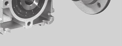
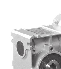
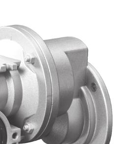
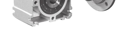
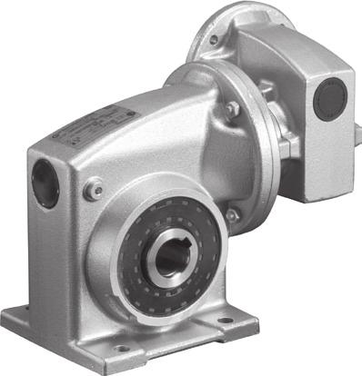
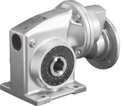
73 Gear units for W + IEC standard motors
74 W + IEC Worm gear units Type SI SI Type SMI n 1 = 1400 min -1 n 1 = 900 min -1 n 1 = 00 min -1 n 1 = 20 min -1 i ges i sch i vor n 2 M 2max P emax n 2 M 2max P emax n 2 M 2max P emax n 2 M 2max P emax [min -1 ] [Nm] [kw] [min -1 ] [Nm] [kw] [min -1 ] [Nm] [kw] [min -1 ] [Nm] [kw] SK 1SI , , ,33 2, 278 0,21 SK 1SMI , ,2 6, ,39 3, , , ,69 8,3 29 0,0 4, , , , , ,38 W , , ,71 6, , , , ,7 8, , , , , , , , , ,66 IEC , , , ,96 12, 12, , , , ,86 mm B6, 38, , , , ,09 7, 7, , , , , , , , ,72 SK 1SI , , ,22 2, 16 0,14 SK 1SMI , ,34 6, ,2 3, , , ,4 8,3 17 0,32 4, , , , , ,24 W , , ,4 6, , , , ,64 8, , , , , , , , , ,41 IEC , , , ,27 12, 12, , , , ,27 mm B6, 36, , , , ,27 7, 7, , , , , , , , ,27 SK 1SI , , ,13 2, 93 0,08 SK 1SMI , ,21 6,2 90 0,1 3, , , ,28 8,3 98 0,20 4, , , , , ,14 W , , ,27 6, , , , ,38 8,3 13 0, , , , , , , , ,24 IEC , , , ,34 12, 12, , , , ,30 mm B6, 34, , , , ,38 7, 7, , , , , , , , ,27 SK 1SI , , ,08 2, 2 0,0 SK 1SMI , ,13 6,2 0 0,10 3,1 0, , ,17 8,3 0,12 4,2 61 0, , , , ,09 W , , ,17 6,2 69 0, , , ,23 8,3 7 0, , , , , , , , ,14 IEC , , , ,20 12, 12, , , , ,18 mm B6, 32, , , , ,14 7, 7, , , , , , , , ,14 B26 G103

![-1 ] [Nm] [kw] [min -1 ] [Nm] [kw] SK 1SI 31 100 100 14 21 0,10 9 24 0,08 28 0,06 2, 31 0,04 SK 1SMI 31 80 80 18 22 0,12](/docs-images/75/71794310/images/75-1.jpg "11 26 0,09 6,2 30 0,06 3,1 33 0,04 60 60 23 24 0,14 1 28 0,11 8,3 33 0,08 4,2 36 0,0 0 0 28 26 0,17 18 30 0,13 10 3 0,09")


75 W + IEC Worm gear units Type SI Type SMI n 1 = 1400 min -1 n 1 = 900 min -1 n 1 = 00 min -1 n 1 = 20 min -1 i ges i sch i vor n 2 M 2max P emax n 2 M 2max P emax n 2 M 2max P emax n 2 M 2max P emax [min -1 ] [Nm] [kw] [min -1 ] [Nm] [kw] [min -1 ] [Nm] [kw] [min -1 ] [Nm] [kw] SK 1SI , , ,06 2, 31 0,04 SK 1SMI , ,09 6,2 30 0,06 3,1 33 0, , ,11 8,3 33 0,08 4,2 36 0, , , , ,0 W , , ,11 6,2 41 0, , , ,1 8,3 4 0, , , , , , , , ,09 IEC , , , ,07 12, 12, , , , ,07 mm B30, , , , ,07 7, 7, , , , , , , , ,07 G103 B27


76 W + IEC Helical worm gear units Type SI Type SMI n 1 = 1400 min -1 n 1 = 900 min -1 n 1 = 00 min -1 n 1 = 20 min -1 i ges i sch i vor n 2 M 2max P emax n 2 M 2max P emax n 2 M 2max P emax n 2 M 2max P emax [min -1 ] [Nm] [kw] [min -1 ] [Nm] [kw] [min -1 ] [Nm] [kw] [min -1 ] [Nm] [kw] SK 1SI 7/H , ,1 0, ,11 0, ,07 0,2 39 0,04 SK 1SMI 7/H , ,18 1, ,13 0, ,08 0, , ,3 38 0,22 1, 373 0,16 0, ,10 0, ,0 W , ,26 1,8 39 0,18 1, ,11 0, , , 406 0,32 2, ,22 1,3 44 0,14 0, , ,7 3 0,31 3, ,21 1, ,13 0, , , ,36 3, ,2 2, ,1 1, ,08 IEC , ,46 4, 41 0,32 2, 436 0,19 1, , , ,61 6, ,42 3, ,2 1,7 06 0,14 mm B6, 4, , ,6 7, ,38 4, ,23 2, , ,70 9, ,48, ,29 2, 43 0,16 7 7, , ,64 6, ,38 3, , , , ,4, ,24 SK 1SI 63/H , ,10 0, ,07 0, 196 0,04 0, ,02 SK 1SMI 63/H , ,12 1, ,08 0, ,0 0, , , ,14 1, 219 0,10 0, ,06 0, ,03 W , ,16 1, , ,07 0, 263 0, , 239 0,19 2, ,13 1, ,08 0, , , , ,18 1,7 28 0,11 0, , , ,22 3, , , ,0 IEC ,28 4, 244 0,19 2, 27 0,11 1, , ,3 23 0, ,2 3, ,1 1, ,09 mm B6, 4, , ,33 7, , , , , , ,17 2, 27 0,09 7 7, , ,37 6, ,23 3, , , , , ,1 SK 1SI 0/H , ,06 0,9 10 0,04 0, 110 0,02 0, ,01 SK 1SMI 0/H , ,07 1, ,04 0, ,03 0, , , ,08 1, 123 0,06 0, ,03 0, ,02 W ,8 12 0,09 1, , ,04 0, 148 0, , 134 0,11 2, ,08 1, ,0 0, , , , ,10 1, ,06 0, , , ,13 3, , , ,03 IEC ,16 4, 137 0,11 2, 144 0,07 1,2 1 0, , , ,1 3,3 16 0,09 1, ,0 mm B6, 4, , ,19 7, , , , , , ,10 2, 14 0,0 7 7, , ,22 6, ,13 3,3 10 0, , , , ,08 SK 1SI 40/H ,4 6 0,03 0,9 8 0,02 0, 61 0,01 0,2 66 0,01 SK 1SMI 40/H ,8 60 0,04 1,1 62 0,03 0, ,02 0, , ,3 66 0,0 1, 68 0,03 0, ,02 0, ,01 W ,8 70 0,06 1,8 72 0, ,02 0, 82 0, , 7 0,07 2,2 78 0,0 1,2 82 0,03 0, , ,7 81 0, ,06 1,7 89 0,04 0, , ,6 69 0,07 3,6 72 0, , ,02 IEC ,09 4, 76 0,06 2, 80 0,04 1,2 87 0, ,3 79 0, ,08 3,3 87 0,0 1,7 93 0,03 mm B6, 4, , ,11 7,2 69 0, , , , ,09 7 0,06 2, 81 0,03 7 7, , ,13 6,7 79 0,07 3,3 8 0, , , , ,0 B28 G103

77 W + IEC Double worm gear units Type SI Type SMI n 1 = 1400 min -1 n 1 = 900 min -1 n 1 = 00 min -1 n 1 = 20 min -1 i ges i sch i vor n 2 M 2max P emax n 2 M 2max P emax n 2 M 2max P emax n 2 M 2max P emax [min -1 ] [Nm] [kw] [min -1 ] [Nm] [kw] [min -1 ] [Nm] [kw] [min -1 ] [Nm] [kw] SK 1SI 7/ , ,13 0, ,03 0, ,02 0, ,01 SK 1SMI 7/ , ,14 0, ,03 0, ,02 0,1 06 0, , ,16 0, 426 0,04 0, ,03 0, ,01 W , ,17 0, ,0 0, ,03 0, , , ,19 0, ,06 0, ,04 0, , , , ,08 0, ,0 0, , , ,23 1, ,10 0, ,06 0, ,03 IEC ,3 37 0,2 1, 390 0,12 0, ,07 0, , , , ,1 1, ,09 0, ,0 mm B6, , 3,7 38 0,36 2, ,17 1, ,10 0, , ,7 31 0, ,24 1, ,19 0, , , 6, , ,24 2, ,19 1, , , , ,24 3, ,19 1, ,07 SK 1SI 63/ , ,11 0, ,02 0, ,01 0, ,01 SK 1SMI 63/ , ,14 0, ,03 0, ,02 0,1 06 0, , ,16 0, 426 0,04 0, ,03 0, , , ,17 0, ,0 0, ,03 0, , , ,19 0, ,06 0, ,04 0, , , , ,08 0, ,0 0, , , ,23 1, ,10 0, ,06 0, ,03 IEC ,3 37 0,2 1, 390 0,12 0, ,07 0, , , , ,1 1, ,09 0, ,0 mm B , 3,7 38 0,36 2, ,17 1, ,10 0, , ,7 31 0, ,24 1, ,19 0, , , 6, , ,24 2, ,19 1, , , , ,24 3, ,19 1, ,07 SK 1SI 0/ , ,06 0,3 18 0,01 0, ,01 0, SK 1SMI 0/ , ,07 0, ,02 0, ,01 0, , , ,07 0, 178 0,02 0, ,01 0, , , ,08 0, ,02 0, ,01 0, , , ,09 0, ,03 0, ,02 0, , , , ,04 0, ,02 0, , ,9 19 0,11 1, ,0 0, ,03 0, ,01 IEC ,3 16 0,12 1, 163 0,06 0, ,03 0, , ,1 12 0, ,07 1, ,04 0, ,02 mm B , 3, ,17 2,4 16 0,09 1,3 16 0,0 0, , , , ,10 1, ,06 0, , , 6, , ,13 2,2 17 0,08 1, , , , ,18 3,3 10 0,11 1, ,06 SK 1SI 40/ , ,03 0, ,01 0, , SK 1SMI 40/ ,8 98 0,04 0, ,01 0, ,01 0, , ,04 0, 99 0,01 0, ,01 0, ,93 9 0,0 0,6 98 0,01 0, ,01 0, ,2 93 0,0 0,7 97 0,02 0, ,01 0, , ,6 90 0, ,02 0,6 98 0,01 0, , ,9 88 0,06 1,2 93 0,03 0, ,02 0, ,01 IEC ,3 87 0,07 1, 90 0,03 0, ,02 0, , ,1 84 0, ,04 1,1 94 0,03 0,6 98 0,01 mm B , 3,7 83 0,10 2,4 87 0,0 1,3 92 0,03 0, , ,7 81 0, ,06 1,7 89 0,04 0, , , 6,2 79 0, ,08 2,2 87 0,0 1,1 94 0, ,3 74 0, ,11 3,3 83 0,06 1,7 89 0,04 G103 B29
78 SK 1SI 31 IEC... Worm gear unit motor 68 Ø Ø14 H7 16,3 M6x8 SK 1SI 31 B Ø38 0 IE1 IE2 IE3 SK 1SI 31 IEC63 63 S/L - SP/LP SK 1SI 31 IEC71 71 S/L - SP/LP g g g1bre k kbre Ø14 h6 Worm gear unit for attachment to IEC standard motors M6x8 IEC-standard motor-adapter IEC 6 IEC 6 IEC 63 IEC 63 IEC 63 IEC 71 IEC 71 B14 B B14 B14 B B14 B14 C10 A120 C90 C120 A140 C10 C140 a b c d e f2 3 3, 3 3, 3, 3 3, l s t2 11,4 11,4 12,8 12,8 12,8 16,3 16,3 u B30 G103
79 SK 1SI 31 IEC... Plug-in shafts VA/I VA/II L 68 Ø Ø14 H7 16,3 Output flange B FA/I FA/II + FA/III FA/II FA/III Torque support DA/I 90.. DA/I 31 Covering cap HA G103 B31
80 SK 1SI 40 IEC... Worm gear unit motor 83 Ø Ø18 H7 6 20,8 M8x12 SK 1SI 40 B Ø38 6 IE1 IE2 IE3 SK 1SI 40 IEC63 SK 1SI 40 IEC71 SK 1SI 40 IEC80 63 S/L - SP/LP 71 S/L - SP/LP 80 S / L SH / LH - / LP g g g1bre k kbre Ø18 h6 Worm gear unit for attachment to IEC standard motors M8x12 IEC-standard motor-adapter IEC 6 IEC 6 IEC 63 IEC 63 IEC 63 IEC 71 IEC 71 IEC 71 IEC 80 IEC 80 IEC 80 IEC 90 IEC 90 B14 B B14 B14 B B14 B14 B B14 B14 B B14 B14 C10 A120 C90 C120 A140 C10 C140 A160 C120 C160 A200 C140 C160 a b c d e f2 3 3, 3 3, 3, 3 3, 4 3, 4 4 3, 4 l o 32, 32, 32, 32, 32, 32, 32, 32, 32, 32, 32, 4, 4, s M t2 11,4 11,4 12,8 12,8 12,8 16,3 16,3 16,3 21,8 21,8 21,8 27,3 27,3 u B32 G103
81 SK 1SI 40 IEC... Plug-in shafts VA/I VA/II L 83 Ø Ø18 H7 6 20,8 FA/I FA/II DA/I 90.. DA/I 31 DA/III 90.. DA/III 31 Covering cap HA a Output flange B Torque support c a c h k I III h k G103 B33
82 SK 1SI 0 IEC... Worm gear unit motor 97 Ø Ø2 H7 8 28,3 SK 1SI 0 B M8x14 Ø38 80 IE1 IE2 IE3 SK 1SI 0 IEC63 SK 1SI 0 IEC71 SK 1SI 0 IEC80 SK 1SI 0 IEC90 63 S/L - SP/LP 71 S/L - SP/LP 80 S / L SH / LH - / LP 90 S / L SH / LH SP / LP g g g1bre k kbre o 32, 32, 32, 4, Ø2 h6 Worm gear unit for attachment to IEC standard motors M8x14 IEC-standard motor-adapter IEC 6 IEC 6 IEC 63 IEC 63 IEC 63 IEC 71 IEC 71 IEC 71 IEC 80 IEC 80 IEC 80 IEC 90 IEC 90 B14 B B14 B14 B B14 B14 B B14 B14 B B14 B14 C10 A120 C90 C120 A140 C10 C140 A160 C120 C160 A200 C140 C160 a b c d e f2 3 3, 3 3, 3, 3 3, 4 3, 4 4 3, 4 l o 32, 32, 32, 32, 32, 32, 32, 32, 32, 32, 32, 4, 4, s M t2 11,4 11,4 12,8 12,8 12,8 16,3 16,3 16,3 21,8 21,8 21,8 27,3 27,3 u B34 G103
83 SK 1SI 0 IEC... Plug-in shafts VA/I VA/II L 97 FA/I FA/III Torque support DA/I 90.. DA/I 31 DA/II 90.. DA/II 31 + DA/III 90.. DA/III 31 HA a Ø40 Ø2 H ,3 Output flange B FA/II + FA/III FA/II Covering cap c a c h k h k I II III G103 B3
84 SK 1SI 63 IEC... Worm gear unit motor 117 Ø 3 3 Ø2 H7 8 28,3 SK 1SI 63 B M10x1 Ø IE1 IE2 IE3 SK 1SI 63 IEC63 SK 1SI 63 IEC71 SK 1SI 63 IEC80 SK 1SI 63 IEC90 63 S/L - SP/LP 71 S/L - SP/LP 80 S / L SH / LH - / LP 90 S / L SH / LH SP / LP g g g1bre k kbre Ø2 h6 Worm gear unit for attachment to IEC standard motors M10x1 IEC-standard motor-adapter IEC 6 IEC 6 IEC 63 IEC 63 IEC 63 IEC 71 IEC 71 IEC 71 IEC 80 IEC 80 IEC 80 IEC 90 IEC 90 IEC 90 B14 B B14 B14 B B14 B14 B B14 B14 B B14 B14 B C10 A120 C90 C120 A140 C10 C140 A160 C120 C160 A200 C140 C160 A200 a b c d e f2 3 3, 3 3, 3, 3 3, 4 3, 4 4 3, 4 4 l s M M10 t2 11,4 11,4 12,8 12,8 12,8 16,3 16,3 16,3 21,8 21,8 21,8 27,3 27,3 27,3 u B36 G103
85 SK 1SI 63 IEC... Plug-in shafts VA/I VA/II L 117 Ø 3 3 Ø2 H7 8 28,3 Output flange B FA/I FA/IV FA/II Torque support DA/I 90.. DA/I 31 Covering cap HA G103 B37

86 SK 1SI 7 IEC... Worm gear unit motor 130 Ø Ø3 H ,3 SK 1SI 7 B M12x22 Ø Ø3 h6 IE1 IE2 IE3 SK 1SI 7 IEC71 SK 1SI 7 IEC80 SK 1SI 7 IEC90 SK 1SI 7 IEC100 SK 1SI 7 IEC S/L - SP/LP 80 S / L SH / LH - / LP 90 S / L SH / LH SP / LP 100 L / LA LH / AH LP / AP 112 M MH MP g g g1bre k kbre Worm gear unit for attachment to IEC standard motors M12x22 IEC-standard motor-adapter IEC 71 IEC 71 IEC 71 IEC 80 IEC 80 IEC 80 IEC 90 IEC 90 IEC 90 IEC 100 IEC 100 IEC 100 IEC 112 IEC 112 IEC 112 B14 B14 B B14 B14 B B14 B14 B B14 B14 B B14 B14 B C10 C140 A160 C120 C160 A200 C140 C160 A200 C160 C200 A20 C160 C200 A20 a b c d e f2 3 3, 4 3, 4 4 3, l s M M12 t2 16,3 16,3 16,3 21,8 21,8 21,8 27,3 27,3 27,3 31,3 31,3 31,3 31,3 31,3 31,3 u B38 G103


87 SK 1SI 7 IEC... Plug-in shafts VA/I VA/II L 130 Ø Ø3 H ,3 Output flange B FA/II Torque support DA/I 90.. DA/I 31 Covering cap HA G103 B39
88 SK 1SMI 31 SK 1SMI 31 VX o kbre k 63 g1bre g1 M SK 1SMI 31 AX Ø Øg Ø , Ø14 k , Ø2 H7 Ø14 2, ,3 SK 1SMI 31 LX SK 1SMI 31 AXB(AZB) Ø Ø14 k6 Ø14 h6 IE1 IE2 IE3 63 S / L - SP / LP 71 S / L - SP / LP g g g1bre k kbre o 29, 29, B40 G103
89 SK 1SMI 31 SK 1SMI 31 VZ o kbre k Ø10 g1bre g1 M SK 1SMI 31 AZ Øg Ø14 M6 Ø60 80 SK 1SMI 31 LZ Ø14 k SK 1SMI 31 VF 6 2, 30 Ø2 2, Ø14 H7 2, 16,3 Ø14 k Ø70 Ø10 Output flange B 8 33, FA/I FA/II + F/III FA/II FA/III , 4 2, Ø80 Ø7 Ø8 Ø10 Ø70 8 6,6 Ø6 70 7Ø0 7Ø0 Torque support 90 DA/I DA/I 31 Covering cap HA , Ø10, 47 G103 B41
90 SK 1SMI 40 SK 1SMI 40 VX o kbre k 78 g1bre g1 M SK 1SMI 40 AX Ø Øg Ø , 40 Ø18 k , Ø H7 Ø18 6 2, 20,8 SK 1SMI 40 LX SK 1SMI 40 AXB(AZB) Ø , 40 Ø18 k6 Ø18 h6 IE1 IE2 IE3 63 S / L - SP / LP 71 S / L - SP / LP 80 S / L SH / LH - / LP g g g1bre k kbre o 32, 32, 32, B42 G103
91 SK 1SMI 40 SK 1SMI 40 VZ SK 1SMI 40 AZ o kbre k Ø120 g1bre g1 M Øg Ø18 M8 Ø Ø18 k , 83 2, SK 1SMI 40 LZ , 40 SK 1SMI 40 VF Ø Ø18 H7 6 20,8 Ø18 k6 6 20, 40 Ø80 Ø Output flange B FA/I FA/II 7 4 Ø110 Torque support DA/I DA/I 31 DA/III DA/III 31 Covering cap HA a a Ø80 Ø60 9 Ø7 Ø100 Ø Ø c Ø10, a c h k I III h k G103 B43
92 SK 1SMI 0 SK 1SMI 0 VX o kbre k 92 g1bre g1 M10 SK 1SMI 0 AX Ø120 Øg Ø Ø2 k , 1 97 Ø H7 Ø2 8 2, 28,3 SK 1SMI 0 LX SK 1SMI 0 AXB(AZB) Ø Ø2 k6 Ø2 h6 IE1 IE2 IE3 63 S / L - SP / LP 71 S / L - SP / LP 80 S / L SH / LH - / LP 90 S / L SH / LH SP / LP g g g1bre k kbre o 32, 32, 32, 4, B44 G103
93 SK 1SMI 0 SK 1SMI 0 VZ o kbre k Ø120 g1bre g1 M10 SK 1SMI 0 AZ Øg Ø2 M8 Ø SK 1SMI 0 LZ Ø2 k6 92 SK 1SMI 0 VF 8 3, 0 Ø , Ø2 H7 8 2, 28,3 Ø2 k Ø110 Ø Output flange B FA/I 8 3, FA/II + FA/III FA/II 8 FA/III 8 3, Ø12 Torque support DA/I DA/I Covering cap HA a a Ø110 Ø70 Ø80 11 Ø9 Ø130 Ø Ø DA/II 90.. DA/II 31 + DA/III 90.. DA/III c Ø10, 64 a c h k I II III h k G103 B4
94 SK 1SMI 63 SK 1SMI 63 VX o kbre k 112 g1bre g1 M10 SK 1SMI 63 AX Ø120 Øg Ø Ø2 k , 2, Ø H7 Ø2 8 28,3 SK 1SMI 63 LX SK 1SMI 63 AXB(AZB) Ø Ø2 k6 Ø2 h6 IE1 IE2 IE3 63 S / L - SP / LP 71 S / L - SP / LP 80 S / L SH / LH - / LP 90 S / L SH / LH SP / LP g g g1bre k kbre o 32, 32, 32, 32, B46 G103
95 SK 1SMI 63 SK 1SMI 63 VZ o kbre k Ø120 g1bre g1 M10 SK 1SMI 63 AZ Øg Ø2 72 M10 Ø SK 1SMI 63 LZ Ø2 k SK 1SMI 63 VF 94 3, 0 Ø 117 2, 3 3 2, 117 H7 Ø2 8 28,3 Ø2 k Ø130 Ø200 1 Output flange B FA/I 94 3, FA/IV , FA/II 94 6 Ø180 Torque support DA/I DA/I Covering cap HA Ø130 Ø110 Ø11 11 Ø11 Ø16 Ø200 1 Ø9 Ø130 Ø Ø Ø10, G103 B47
96 SK 1SMI 7 SK 1SMI 7 VX o kbre k 12 g1bre g1 M12 SK 1SMI 7 AX Ø160 Øg Ø Ø3 k , 2, 67, 130 Ø H7 Ø ,3 SK 1SMI 7 LX SK 1SMI 7 AXB(AZB) Ø Ø3 k6 Ø3 h6 IE1 IE2 IE3 71 S / L - SP / LP 80 S / L SH / LH - / LP 90 S / L SH / LH SP / LP 100 L / LA LH / AH LP / AP B48 G M MH MP g g g1bre k kbre o
97 SK 1SMI 7 SK 1SMI 7 VZ o kbre k Ø160 g1bre g1 M12 SK 1SMI 7 AZ Øg Ø3 M12 Ø SK 1SMI 7 LZ Ø3 k SK 1SMI 7 VF Ø , , 130 H7 Ø ,3 Ø3 k Output flange B Ø200 FA/II Torque support DA/I DA/I Covering cap HA Ø130 Ø , 14 Ø , Ø10, 81, G103 B49
98 SK 1SI /H10 SK 1SMI /H10 Helical input stage Helical input stage Type H10 The helical input stage has a speed ratio i=10 and is suitable for the worm gear modules SK 1SI 40, SK 1SI 0 and SK 1SI 63 as well as for the worm gear units SK 1SMI 40, SK 1SMI 0 and SK 1SMI 63. The helical input allows the construction of 2-stage helical worm gear motors and helical worm gear unit. Helical worm gear motors SK 1SI... SK 1SMI... IE1 IE2 IE3 63 S / L - SP / LP 71 S / L - SP / LP g g g1bre k kbre Helical worm gear unit for attachment to IEC standard motors SK 1SI... SK 1SMI... IEC-standard motor-adapter IEC 6 IEC 6 IEC 63 IEC 63 IEC 63 IEC 71 IEC 71 IEC 71 IEC 80 IEC 80 IEC 80 B14 B B14 B14 B B14 B14 B B14 B14 B C10 A120 C90 C120 A140 C10 C140 A160 C120 C160 A200 a b c d e f2 3 3, 3 3, 3, 3 3, 4 3, 4 4 l s M10 t2 11,4 11,4 12,8 12,8 12,8 16,3 16,3 16,3 21,8 21,8 21,8 u B0 G103

99 Helical input stage SK 1SI 7/H10 SK 1SMI 7/H10 Helical input stage Type H10 The helical input stage has a speed ratio i=10 and is suitable for the worm gear modules SK 1SI 7, as well as for the worm gear units SK 1SMI 7. The helical input allows the construction of 2-stage helical worm gear motors and helical worm gear unit. Helical worm gear motors SK 1SI SK 1SMI... IE1 IE2 IE3 63 S / L - SP / LP 71 S / L - SP / LP 80 S / L SH / LH - / LP g g g1bre k kbre Helical worm gear unit for attachment to IEC standard motors SK 1SI SK 1SMI... IEC-standard motor-adapter IEC 6 IEC 6 IEC 63 IEC 63 IEC 63 IEC 71 IEC 71 IEC 71 IEC 80 IEC 80 IEC 80 B14 B B14 B14 B B14 B14 B B14 B14 B C10 A120 C90 C120 A140 C10 C140 A160 C120 C160 A200 a b c d e f2 3 3, 3 3, 3, 3 3, 4 3, 4 4 l s M10 t2 11,4 11,4 12,8 12,8 12,8 16,3 16,3 16,3 21,8 21,8 21,8 u G103 B1
100 SK 1SI /31 SK 1SMI /31 Double worm gear adapter Double worm gear unit adapter The double worm gear unit is an adapter which allows the worm gear SK 1SI 31 to be used as and input stage for the worm gear SK 1SI 40, SK 1SI 0 and SK 1SI 63 as well as for the worm gear units SK 1SMI 40, SK 1SMI 0 and SK 1SMI 63. The double worm gear allows the construction of double worm gear motors and double worm gear units. Double worm gear motors SK 1SI... SK 1SMI... IE1 IE2 IE3 63 S / L - SP / LP 71 S / L - SP / LP g g g1bre k kbre Double worm gear unit for attachment to IEC standard motors SK 1SI... SK 1SMI... IEC-standard motor-adapter IEC 6 IEC 6 IEC 63 IEC 63 IEC 63 IEC 71 IEC 71 B14 B B14 B14 B B14 B14 C10 A120 C90 C120 A140 C10 C140 a b c d e f2 3 3, 3 3, 3, 3 3, l s t2 11,4 11,4 12,8 12,8 12,8 16,3 16,3 u B2 G103
101 Double worm gear adapter SK 1SI 7/40 SK 1SMI 7/40 Double worm gear adapter The double worm gear is an adapter, which allows the worm gear unit SK 1SI 40 to be used as the input stage for the worm gear SK 1SI 7 and for the worm gear unit SK 1SMI 7. The double worm gear allows the construction of double worm gear motors and double worm gear units. Double worm gear motor SK 1SI... SK 1SMI... IE1 IE2 IE3 63 S / L - SP / LP 71 S / L - SP / LP g g g1bre k kbre Double worm gear unit for attachment to IEC standard motors SK 1SI... SK 1SMI... IEC-standard motor-adapter IEC 6 IEC 6 IEC 63 IEC 63 IEC 63 IEC 71 IEC 71 IEC 71 IEC 80 IEC 80 IEC 80 IEC 90 IEC 90 B14 B B14 B14 B B14 B14 B B14 B14 B B14 B14 C10 A120 C90 C120 A140 C10 C140 A160 C120 C160 A200 C140 C160 a b c d e f2 3 3, 3 3, 3, 3 3, 4 3, 4 4 3, 4 l o 32, 32, 32, 32, 32, 32, 32, 32, 32, 32, 32, 4, 4, s M t2 11,4 11,4 12,8 12,8 12,8 16,3 16,3 16,3 21,8 21,8 21,8 27,3 27,3 u G103 B3
102 IEC standard motor adapter a2 b2 e2 f2 s2 d2 l2 t2 u2 o o o o o o Motor-adapter SI 31 SI 40 SI 0 SI 63 SI 7 H10 IEC 6 B14 C ,4 3 29, 32, 32, 32, 32, IEC 6 B A , ,4 3 29, 32, 32, 32, 32, IEC 63 B14 C ,8 4 29, 32, 32, 32, 32, IEC 63 B14 C , ,8 4 29, 32, 32, 32, 32, IEC 63 B A , ,8 4 29, 32, 32, 32, 32, IEC 71 B14 C ,3 29, 32, 32, 32, 36 32, IEC 71 B14 C , ,3 29, 32, 32, 32, 36 32, IEC 71 B A ,3-32, 32, 32, 36 32, IEC 80 B14 C , ,8 6-32, 32, 32, 36 32, IEC 80 B14 C ,8 6-32, 32, 32, 36 32, IEC 80 B A M ,8 6-32, 32, 32, 36 32, IEC 90 B14 C , ,3 8-4, 4, 32, 36 - IEC 90 B14 C ,3 8-4, 4, 32, 36 - IEC 90 B A M ,3 8-4, 4, 32, 36 - IEC 100 B14 C , IEC 100 B14 C , IEC 100 B A M , IEC 112 B14 C , IEC 112 B14 C , IEC 112 B A M , Motor-adapter Available version SK 1SI 31 SK 1SI 40 SK 1SI 0 SK 1SI 63 SK 1SI 7 SK H10 IEC 6 B14 C10 IEC 6 B A120 IEC 63 B14 C90 * * * * * IEC 63 B14 C120 IEC 63 B A140 IEC 71 B14 C10 * * * * * * IEC 71 B14 C140 IEC 71 B A160 IEC 80 B14 C120 * * * * IEC 80 B14 C160 IEC 80 B A200 IEC 90 B14 C140 * * * * IEC 90 B14 C160 IEC 90 B A200 IEC 100 B14 C160 IEC 100 B14 C200 IEC 100 B A20 * IEC 112 B14 C160 IEC 112 B14 C200 IEC 112 B A20 * * Standard B4 G103
![IEC three-phase motor / brake motor Three-phase motors M B P 1 n 1 a1 k c1 d t f1 g i2 s3 m [Nm] [kw] [min -1 ] b1 [kg] e1 T u s2 g1 l n p 63 S/4 - SP/4 B14 C90 0,12 133 90 8 11 12, 2, 130 23 M20 12](/docs-images/75/71794310/images/103-0.jpg "3,6 21 60 7 M4 4 M 11 23 100 100 63 L/4 - LP/4 B14 C90 0,18 130 90 8 11 12, 2, 130 23 M20 12 4,2 21 60 7 M4 4 M 11 23 100 100 71 S/4 - SP/4 B14 C10 0,2 1380 10 12 14 16 2, 14 30 M20 20,4 244 70 8 M")
103 IEC three-phase motor / brake motor Three-phase motors M B P 1 n 1 a1 k c1 d t f1 g i2 s3 m [Nm] [kw] [min -1 ] b1 [kg] e1 T u s2 g1 l n p 63 S/4 - SP/4 B14 C90 0, , 2, M , M4 4 M L/4 - LP/4 B14 C90 0, , 2, M , M4 4 M S/4 - SP/4 B14 C10 0, , M20 20, M M L/4 - LP/4 B14 C10 0, , M , M M S/4 SH/4 - B14 C120 0, , 3, M M6 6 M L/4 LH/4 LP/4 B14 C120 0, , 3, M M6 6 M S/4 SH/4 SP/4 B14 C140 1, , M M8 8 M L/4 LH/4 LP/4 B14 C140 1, , M M8 8 M L/4 LH/4 LP/4 B A20 2, , M M LA/4 AH/4 AP/4 B A20 3, , M M M/4 - - B A20 4, , M M MH/4 MP/4 B A20 4, , M M Brake motors M B P 1 n 1 a1 k c1 d t f1 g i2 s3 m [Nm] [kw] [min -1 ] b1 [kg] e1 T u s2 g1 l n p 63 S/4 - SP/4 B14 C90 BRE 0, , 2, M20 19, M4 4 M L/4 - LP/4 B14 C90 BRE 0, , 2, M , M4 4 M S/4 - SP/4 B14 C10 BRE 0, , M , M M L/4 - LP/4 B14 C10 BRE 0, , M , M M S/4 SH/4 - B14 C120 BRE 0, , 3, M M6 6 M L/4 LH/4 LP/4 B14 C120 BRE , , 3, M M6 6 M S/4 SH/4 SP/4 B14 C140 BRE , , M M L/4 LH/4 LP/4 B14 C140 BRE , , M M8 8 M L/4 LH/4 LP/4 B A20 BRE , , M M LA/4 AH/4 AP/4 B A20 BRE , , M M M/4 - - B A20 BRE , , M M MH/4 MP/4 B A20 BRE , , M M G103 B

104 SK 1SI W SK 1SMI W Type W - free drive shaft Free Drive Shaft - Type W The Type W free drive shaft implements a free drive shaft for the worm dear modules SK 1SI 40, SK 1SI 0, SK 1SI 63, SK 1SI 7 as well as for the worm gear units SK 1SMI 40, SK 1SMI 0, SK 1SMI 63, SK 1SMI 7 and the helical gear input stage H10. SK 1SI W SK 1SMI W SK 1SI 7 - W SK 1SMI 7 - W B6 G103
105 Notes G103 B7
106 Notes B8 G103

107 An overview of the NORD range Contens NORD UNIVERSAL WORM GEAR UNITS A SPEEDS 0 Hz Hz mm mm CONSTANT FESTE DREHZAHLEN Innovative drive solutions for more than 100 industries Mechanic Products Helical, Parallel Shaft, Helical Bevel and Helical Worm Gear Units Electrical Products Electric motors in all efficiency classes Electronic Products Centralized and decentralized frequency inverters, Motor starters 7 state-of-the-art production plants for all drive components 36 subsidiaries on continents provide on-site storage, assembly centers, technical support and customer service More than employees around the world create customized solutions EN Getriebebau NORD GmbH & Co. KG Getriebebau-Nord-Straße Bargteheide, Germany Fon +49 (0) 432 / Fax +49 (0) 432 / info@nord.com, Member of the NORD DRIVESYSTEMS Group EN Headquarters: CONSTANT SPEEDS G Hz mm Intelligent Drivesystems, Worldwide Services DRIVESYSTEMS VERSIONS AVAILABLE B - 2 G100 MAXXDRIVE Industrial gear units UNICASE housing 0 / 60 Hz Parallel-Axis Right-Angle GEAR UNIT MOTOR DATA Power and speed tables B - 4 Power and speed ratio tables W and IEC adapters B - 2 ELECTRONIC VARIABLE SPEED DRIVES NORD DRIVESYSTEMS GROUP Headquarters and Technology Center in Bargteheide near Hamburg, Germany Innovative drive solutions for more than 100 industries Mechanic Products Helical, Parallel Shaft, Helical Bevel and Helical Worm Gear Units Electrical Products Electric motors in all efficiency classes Electronic Products Centralized and decentralized frequency inverters, Motor starters 7 state-of-the-art production plants for all drive components 36 subsidiaries on continents provide on-site storage, assembly centers, technical support and customer service More than employees around the world create customized solutions Headquarters: G4014 Mat.-Nr / 4214 G4014 Electronic variable speed drives NORDBLOC.1 Helical geared motors Helical geared motors Parallel geared motors Bevel geared motors Helical worm geared motors ELECTRONIC VARIABLE SPEED DRIVES G4014 EN AAAAAAA- Headquarters and Technology Center in Bargteheide near Hamburg, Germany Getriebebau NORD GmbH & Co. KG Getriebebau-Nord-Straße Bargteheide, Germany Fon +49 (0) 432 / Fax +49 (0) 432 / info@nord.com, Member of the NORD DRIVESYSTEMS Group 0/60 Hz mm NORD GEAR - LARGE INDUSTRIAL GEAR UNITS Mounting variants Direct motor mounting / IEC motor mounting Assembly combinations Versions Order check list Selection list structure Tolerances NORD DRIVESYSTEMS GROUP G1000 Mat.-Nr / NORD DRIVESYSTEMS GROUP Headquarters and Technology Center in Bargteheide near Hamburg, Germany Innovative drive solutions for more than 100 industries Mechanic Products Helical, Parallel Shaft, Helical Bevel and Helical Worm Gear Units Electrical Products Electric motors in all efficiency classes Electronic Products EN PRODUCT OVERVIEW G4014 NORDBLOC.1 Helical Gear Units, Helical Gear Units, Parallel Gear Units, Helical-Bevel Gear Units, Helical-Worm Gear Units Intelligent Drivesystems, Worldwide Services Centralized and decentralized frequency inverters, Motor starters 7 state-of-the-art production plants Large Industrial Gear Units for all drive components 36 subsidiaries on continents provide on-site storage, assembly centers, technical support and customer service Parallel-Axis and Right-Angle More than employees around the world High Precision, Long Life, Low Maintenance create customized solutions EN Headquarters: Getriebebau NORD GmbH & Co. KG Getriebebau-Nord-Straße Bargteheide, Germany Fon +49 (0) 432 / Fax +49 (0) 432 / info@nord.com, G100 Mat.-Nr / 116 AAAAAAAA- Intelligent Drivesystems, Worldwide Services DRIVESYSTEMS Member of the NORD DRIVESYSTEMS Group G100 Construction kit system Overview of versions Overview of IEC / NEMA adapters Overview of direct motor mounting Technical explanations Installation positions Gear unit selection Motor selection G1000 Fixed speeds UNICASE housing 0 Hz, 60 Hz NORDBLOC.1 Helical geared motors Helical geared motors Parallel geared motors Bevel geared motors Helical worm geared motors G1000 GENERAL PRODUCT INFORMATION A - 4 PRODUCT OVERVIEW G100 0/60 Hz mm SK SK 107 Gear Units DIMENSIONED DRAWINGS B - 30 Intelligent Drivesystems, Worldwide Services M7000 Motors Efficiency classes IE1, IE2, IE3 NORD DRIVESYSTEMS Group Headquarters and Technology center in Bargteheide close to Hamburg Innovative drive solutions for more than 100 branches of industry Mechanical products paralell shaft, helical gear, bevel gear and worm gear units Electrical products IE2/IE3/IE4 motors Electronic products centralised and decentralised frequency inverters, motor starters and field distribution systems 7 state-of-the-art production plants for all drive components Subsidiaries and distributors in 89 countries on continents provide local stocks, assembly, production, technical support and customer service MOTORS More than 3,00 employees throughout the world create customer oriented solutions M7000 Mat.-Nr / 3817 Headquarters: Getriebebau NORD GmbH & Co. KG Getriebebau-Nord-Straße Bargteheide, Germany T: +49 (0) 432 / F: +49 (0) 432 / info@nord.com, Member of the NORD DRIVESYSTEMS Group EN M7000 EN MOTORS M7000 Intelligent Drivesystems, Worldwide Services Intelligent Drivesystems, Worldwide Services F3018 Frequency inverter SK180E F3020 Frequency inverter SK200E DE SK 180E Dezentrale Antriebstechnik Frequenzumrichter SK 200E F 3020 DE

108 Intelligent Drivesystems, Worldwide Services NORD Drivesystems NORD DRIVESYSTEMS Group G103 WORM GEAR UNITS Headquarters and Technology center in Bargteheide close to Hamburg Innovative drive solutions for more than 100 branches of industry Mechanical products paralell shaft, helical gear, bevel gear and worm gear units Electrical products IE2/IE3/IE4 motors EN Electronic products centralised and decentralised frequency inverters, motor starters and field distribution systems 7 state-of-the-art production plants for all drive components Subsidiaries and distributors in 89 countries on continents provide local stocks, assembly, production, technical support and customer service More than employees throughout the world create customer oriented solutions EN Getriebebau NORD GmbH & Co. KG Getriebebau-Nord-Straße Bargteheide, Germany T: +49 (0) 432 / F: +49 (0) 432 / info@nord.com, Member of the NORD DRIVESYSTEMS Group G103 Mat.-Nr / 3717 Headquarters: G103 UNIVERSAL Worm gear units SI and SMI
Intelligent Drivesystems, Worldwide Services. ELECTRONIC DRIVE SYSTEMS UP TO 160 kw
 Intelligent Drivesystems, Worldwide Services EN ELECTRONIC DRIVE SYSTEMS UP TO 160 kw NORD DRIVESYSTEMS Group Headquarters and Technology Centre in Bargteheide, close to Hamburg Innovative drive solutions
INTELLIGENT DRIVESYSTEMS, WORLDWIDE SERVICES DRIVE SOLUTIONS FOR THE FOOD AND BEVERAGE INDUSTRY
 INTELLIGENT DRIVESYSTEMS, WORLDWIDE SERVICES EN DRIVE SOLUTIONS FOR THE FOOD AND BEVERAGE INDUSTRY NORD DRIVESYSTEMS Intelligent Drivesystems, Worldwide Services NORD DRIVE SOLUTIONS FOR THE FOOD AND BEVERAGE
Intelligent Drivesystems, Worldwide Services MODULAR INDUSTRIAL GEAR UNITS
 Intelligent Drivesystems, Worldwide Services EN MODULAR INDUSTRIAL GEAR UNITS NORD DRIVESYSTEMS INDUSTRIAL GEAR UNITS Main fields of application n Materials transport (belt, plate, screw & chain conveyors,
Intelligent Drivesystems, Worldwide Services. GB Drive Solutions for Airports DRIVESYSTEMS
 Intelligent Drivesystems, Worldwide Services GB Drive Solutions for Airports NORD Intelligent Drivesystems, Worldwide Services Partners in Motion For large and small Whether for baggage handling, moving
INTELLIGENT DRIVE SYSTEMS, WORLDWIDE SERVICES INTELLIGENT DRIVESYSTEMS, WORLDWIDE SERVICES
 INTELLIGENT DRIVE SYSTEMS, WORLDWIDE SERVICES INTELLIGENT DRIVESYSTEMS, WORLDWIDE SERVICES EN DRIVE SOLUTIONS FOR SEWAGE PLANTS NORD DRIVESYSTEMS Intelligent Drivesystems, Worldwide Services NORD DRIVE
DRIVE SOLUTIONS FOR THE TYRE INDUSTRY DRIVESYSTEMS
 INTELLIGENT DRIVESYSTEMS, WORLDWIDE SERVICES EN DRIVE SOLUTIONS FOR THE TYRE INDUSTRY DRIVESYSTEMS NORD DRIVESYSTEMS Intelligent Drivesystems, Worldwide Services NORD DRIVE SOLUTIONS FOR THE TYRE INDUSTRY
DRIVE SOLUTIONS FOR BAGGAGE HANDLING SYSTEMS
 INTELLIGENT DRIVE SYSTEMS, WORLDWIDE SERVICES EN DRIVE SOLUTIONS FOR BAGGAGE HANDLING SYSTEMS NORD DRIVESYSTEMS Intelligent Drivesystems, Worldwide Services NORD DRIVE SOLUTIONS FOR THE AIRPORT INDUSTRY
Intelligent Drivesystems, Worldwide Services ELECTRONIC DRIVE SYSTEMS UP TO 200 HP
 Intelligent Drivesystems, Worldwide Services EN ELECTRONIC DRIVE SYSTEMS UP TO 200 HP NORD DRIVESYSTEMS Group Headquarters and Technology Centre in Bargteheide, close to Hamburg Innovative drive solutions
ALUMINIUM GEAR UNITS WITH SMOOTH MOTORS kw
 Intelligent Drivesystems, Worldwide Services ALUMINIUM GEAR UNITS WITH SMOOTH MOTORS 0.12 1.1 kw EN PRODUCT CATALOGUE TI60-0002 THE ADVANTAGES OF ALUMINIUM GEAR UNITS Information Corrosion Resistant Aluminium
INTELLIGENT DRIVESYSTEMS, WORLDWIDE SERVICES DRIVE SOLUTIONS FOR CRANE SYSTEMS. A6035_ _4518_F1_16S.indd :43
 INTELLIGENT DRIVESYSTEMS, WORLDWIDE SERVICES EN DRIVE SOLUTIONS FOR CRANE SYSTEMS A6035_6042202_4518_F1_16S.indd 1 12.12.18 12:43 NORD DRIVESYSTEMS Intelligent Drivesystems, Worldwide Services NORD DRIVE
INTELLIGENT DRIVESYSTEMS, WORLDWIDE SERVICES DRIVE SOLUTIONS FOR INTRALOGISTICS AND WAREHOUSING
 INTELLIGENT DRIVESYSTEMS, WORLDWIDE SERVICES EN DRIVE SOLUTIONS FOR INTRALOGISTICS AND WAREHOUSING NORD DRIVESYSTEMS Intelligent Drivesystems, Worldwide Services NORD DRIVE SOLUTIONS FOR THE INTRALOGISTICS
SEALING SOLUTIONS FOR YOUR DRIVES
 Intelligent Drivesystems, Worldwide Services SEALING SOLUTIONS FOR YOUR DRIVES EN SEALING SYSTEMS FOR NORD GEAR UNITS AND GEARED MOTORS SEALING SYSTEMS FOR NORD GEAR UNITS AND GEARED MOTORS NORD DRIVESYSTEM
EFFICIENCY REGULATIONS FOR MOTORS AND MOTOR SYSTEMS
 Intelligent Drivesystems, Worldwide Services EFFICIENCY REGULATIONS FOR MOTORS AND MOTOR SYSTEMS EN INTERNATIONAL REQUIREMENTS EFFICIENCY REGULATIONS FOR MOTORS AND MOTOR SYSTEMS Electric drives in industrial
ATEX LABELLING FOR MOTORS AND GEAR UNITS
 ATEX LABELLING FOR MOTORS AND GEAR UNITS EN ATEX INFORMATION GAS AND DUST COMPLETE DRIVE SOLUTIONS FROM A SINGLE SOURCE RELIABLE n Reliable products n Coordinated components n NORD's own development and
Geared motors for use in Zone 22 - Category 3D
 Notes on the suitability of the gear units listed in this catalogue With the exception of variable speed gear units and industrial gear units, this catalogue contains all of the Getriebebau NORD gear unit
EFFICIENCY REGULATIONS FOR MOTORS AND MOTOR SYSTEMS
 Intelligent Drivesystems, Worldwide Services EFFICIENCY REGULATIONS FOR MOTORS AND MOTOR SYSTEMS EN INTERNATIONAL REQUIREMENTS EFFICIENCY REGULATIONS FOR MOTORS AND MOTOR SYSTEMS Electric drives in industrial
COMPLETE DRIVE SYSTEMS FROM A SINGLE SOURCE
 COMPLETE DRIVE SYSTEMS FROM A SINGLE SOURCE EN TECHNICAL MANUAL January 2018 NORD DRIVESYSTEMS Group Headquarters and technology centre in Bargteheide near Hamburg Innovative drive solutions for more than
.1 Standard Features NORDBLOC.1 SERIES. Intelligent Nordbloc Drivesystems. Innovative Design F1012
 Intelligent Nordbloc Drivesystems.1 Standard Features NORDBLOC.1 SERIES F1012 Bearing Design The design of the bearing systems is a key innovation in the new NORDBLOC.1 units. The output bearing is greatly
ELECTRIC MOTORS kw PRODUCT CATALOGUE M7002
 ntelligent Drivesystems, Worldwide Services ELECTRC MTRS 30 55 kw PRDUCT CATALGUE M700 PTNS 30 55 kw MTRS nformation Abbreviations Meaning BRE + Brake / brake torque + sub-option DBR + Double brake + sub-option
technology made in Italy
 technology made in Italy GB RD * * VS made in China Technology Made in Italy Since 1955 Varvel has been making speed reducers and variators for light industry applications. Reliable partner in power transmission
BEVEL GEAR UNITS ZZ-SERVOLINE
 BEVEL GEAR UNITS ZZ-SERVOLINE ZZ-SERVOLINE GEARBOX DESIGN AND FUNCTIONAL FEATURES Gear Ratios i= 3:1 i= 4:1 i= 5:1 i= 6:1 i= 8:1 i= 10:1 i= 12:1 i= 15:1 Spiral Bevel Gear KLINGELNBERG tooth system Hypoid
IP66 GSW GEAR BOX MOTOR SERIES
 IP66 GSW GEAR BOX MOTOR SERIES Three Phase Aluminium Gear Box Motors Australian Version October 2013 CONTENTS INTRODUCTION Pg 3 MATERIALS AND CONSTRUCTION Pg 3-4 SERIES OVERVIEW Pg 5 PERFORMANCE DATA Pg
B 2000 en. Explosion-protected gear units. Operating and Assembly Instructions
 B 2000 en Explosion-protected gear units Operating and Assembly Instructions Explosion-protected gear units Operating and Assembly Instructions General safety and operating instructions 1. General Depending
4 Project planning for drives
 Additional publications Project planning for drives. Additional publications For more detailed information about the project planning for drives, refer to the website of SEW-EURODRIVE where you can download
Intelligent Drivesystems NORD GRIPMAXX. Keyless Bushing System DRIVESYSTEMS F5210
 Intelligent Drivesystems NORD GRIPMAXX Keyless Bushing System F5210 The NORD GRIPMAXX Keyless Bushing System Concept Overview The NORD Gripmaxx Bushing System offers keyless interchangeable bushings for
KEB Gear units & Motors 2014
 Introduction KEB Gear units & Motors 2014 Contents Introduction 2 designation... 2 Product description... 3 Assembly / Disassembly notes when using gear units with hollow shaft... 5 Drive selection...
Demag KB conical-rotor brake motors. Drives with unique principle
 Demag KB conical-rotor brake motors Drives with unique principle 37468 Demag KB conical rotor brake motors: Demag KB conical rotor brake motors offered by Demag Cranes & Components feature a unique principle:
Standards Regulations Nomenclature
 Standards Regulations Nomenclature Nomenclature Helical worm gear units Sizes 2-stage 3-stage SK 02040 SK 02050 SK 13050 SK 12063 SK 13063 SK 12080 SK 13080 SK 32100 SK 33100 SK 42125 SK 43125 Order examples:
Lenze. Drives with worm gearboxes 52.
 6 887 Lenze Drives with worm gearboxes 5. Lenze Drive Systems GmbH, Postfach 0 5, D-76 Hameln, Site: Groß Berkel, Hans-Lenze-Straße, D-855 Aerzen, Phone ++9 (0) 55 8-0, Telefax ++9 (0) 55 8- E-Mail: Lenze@Lenze.de
Planning and Commissioning Guideline for NORD IE4 Synchronous Motors with NORD Frequency Inverters
 Getriebebau NORD GmbH & Co. KG Getriebebau-Nord-Straße 1 22941 Bargteheide, Germany www.nord.com Planning and Commissioning Guideline for NORD IE4 Synchronous Motors with NORD Frequency Inverters General
Series J Shaft Mounted Gearbox
 Series J Shaft Mounted Gearbox Technical Up to - 600kW / 57,000 Nm Industrial Gearbox CJ-2.00GBA1211 PRODUCTS IN THE RANGE Serving an entire spectrum of mechanical drive applications from food, energy,
ODP SERIES PREMIUM INDUSTRIAL OPEN DRIP PROOF MOTORS C280M to C355LB Frame. Australian Version October 2013
 ODP SERIES PREMIUM INDUSTRIAL OPEN DRIP PROOF MOTORS C280M to C355LB Frame Australian Version October 2013 ODP SERIES (OPEN DRIP PROOF) PREMIUM INDUSTRIAL OPEN DRIP PROOF MOTORS, C280M TO C355LB FRAME
5 Project Planning for Gear Units
 Efficiency of SEW gear units Project Planning for Gear Units.1 Efficiency of SEW gear units General information The efficiency of gear units is mainly determined by the gearing and bearing friction. Keep
DC motors. G-motion. CTi Automation - Phone: Fax: Web:
 G-motion No matter which drive solution you imagine, we make your dreams come true. True to our slogan (one stop shopping) we offer you a complete programme of electronic and mechanical drive systems which
TQ-TQK-TR-MP LC-LCK-SL-KR Series. Precision Planetary Gearboxes
 TQ-TQK-TR-MP LC-LCK--KR Series Precision Planetary Gearboxes OUR PRODUCTS AT A GLANCE PRODUCT INLINE RIGHT ANGLE PRODUCT LINE-UP CONFIGURATIONS HIGH PERFORMANCE NEW TQ NEW TQK Yes Yes Highest Precision
ELECTRIC MOTORS. Selection. Starting torque and nominal torque
 SELECTION PROCEDURE The output powers published overleaf are based upon continuous maximum rating conditions. Therefore design factors for above average running periods do not normally affect the selection.these
Electromagnetic clutch-brake combinations INTORQ
 Electromagnetic clutch-brake combinations INTORQ 14.800 14.867 7.5 120 Nm setting the standard 2 CBC en 5/2005 Contents Clutch-brake combinations Product information 4 Type code 6 Design selection 8 Overview
Shaft Couplings Flange-Couplings Rigid Shaft Couplings Flexible Couplings
 Shaft Couplings Flange-Couplings Rigid Shaft Couplings Flexible Couplings 44 Edition 2013/2014 RINGSPANN Registered Trademark of RINGSPANN GmbH, Bad Homburg 2 Table of Contents Flange-Couplings Page Flange-Couplings
1.2 Selecting the gear unit Service life of bearings Version and input section Mounting positions MP
 SUMMARY 1 General information... 3 1.1 Symbols, units and definitions... 3 1.2 Selecting the gear unit... 4 1.3 Service life of bearings... 6 2 Features of MP series... 8 3 Ordering code... 10 3.1 Version
3947 en / b
 3947 en - 06.2006 / b FOOD INDUSTRY Drive systems As a worldwide specialist in drive systems, industrial processes and generators, LEROY-SOMER has supported its customers evolving needs for more than 80
High quality and washdown tolerant
 STAINESS STEE MOTORS For the food and processing industry High quality and washdown tolerant Stainless Steel Motors Designed for Demanding Environments Stainless steel motors BJ-Gear A/S produces stainless
Süddeutsche Elektromotoren-Werke
 Mechantronic Drive SolutionsMOVIGEAR Süddeutsche Elektromotoren-Werke and DRC - more than 100.000 units in worldwide operation What began in Bruchsal, Germany, 85 years ago in a small workshop with 16
Brake Motors Aluminium Frame Improved Efficiency EFF2
 Motors Energy Automation Coatings Brake Motors Aluminium Frame Improved Efficiency EFF2 Standard Features: Three-phase, multivoltage, IP55, TEFC Output: 0.12 up to 11kW Frames: 63 up to 132M Voltage: 220-240/380-415V
Worm geared motors. Orientation 6/2 Overview 6/3 Modular system. General technical data 6/4 Permissible radial force
 Siemens AG 2011 Orientation /2 Overview /3 Modular system General technical data / Permissible radial force Geared motors up to 1.1 kw / Selection and ordering data Transmission ratios and maximum torques
alpha Value Line - NPS Sizing and Technical Data Efficient Flexible Reliable
 alpha Value Line - NPS Sizing and Technical Data Efficient Flexible Reliable alpha Value Line NP NPS NPL NPT NPR Ratios 3-100 Torsional backlash [arcmin] 8 Output type Smooth output shaft Grooved output
Standardmotoren Standard motors
 Standardmotoren Standard motors Contents Product description 2/2 Overview of technical data 2/5 2 Series W4.R for Premium Efficiency IE3 2/6 Series WE.R for High Efficiency IE2 2/14 Series K2.R for Standard
General Purpose Cast Iron Motors
 General Purpose Cast Iron Motors Totally enclosed squirrel cage three phase low voltage motors, Sizes 71-355, 0.25 to 250 kw www.abb.com/motors&drives > Motors > Low voltage motors > General purpose motors
POWER GEAR. The HighSpeed bevel gearbox.
 MS-Graessner GmbH & Co. KG THE GEAR COMPANY POWER GEAR The HighSpeed bevel gearbox HS www.graessner.de Nothing but highlights! Designed for special requirements no adaption, no compromises: There are decades
Gearmotors \ Industrial Gear Units \ Drive Engineering \ Drive Automation \ Services. Gearmotors A3.D01. Catalog. Edition 04/ / EN
 Gearmotors \ Industrial Gear Units \ Drive Engineering \ Drive Automation \ Services Gearmotors A3.D0 Edition 04/2004 22560 / EN Catalog SEW-EURODRIVE Driving the world Contents The SEW-EURODRIVE Group
Asynchronous and synchronous motors for SINAMICS S120 1PL6 asynchronous motors Forced ventilation, IP23 degree of protection
 Overview 1PL6 motors, shaft heights 180 to 22 Benefits 7 Extremely high power density with small motor dimensions (0 to 60 % higher output as compared to 1PH7 in degree of protection IP) 7 Speed down to
DYNA GEAR. The highly dynamic servo right angle gearbox.
 MS- Gr a es s ne r GmbH & Co. K G THE GEAR COM PAN Y The highly dynamic servo right angle gearbox Internal highlights The design of the DynaGear range has been influenced by extremely varied applications
Catalog Mars Low voltage Brake motors
 Catalog Mars 2014 Low voltage Brake motors We provide motors, generators and mechanical power transmission products, services and expertise to save energy and improve customers processes over the total
5 Project Planning for Gear Units
 Efficiency of gear units Project Planning for Gear Units.1 Efficiency of gear units General information The efficiency of gear units is mainly determined by the gearing and bearing friction. Keep in mind
1.2 Selecting the gear unit Service life of bearings Version and input section Mounting positions TR
 SUMMARY 1 General information... 3 1.1 Symbols, units and definitions... 3 1.2 Selecting the gear unit... 4 1.3 Service life of bearings... 6 2 Features of TR series... 8 3 Ordering code... 10 3.1 Version
Permanent-magnet synchronous motors
 Permanent-magnet synchronous motors Contents Product description 12/2 Overview of technical data 12/4 Motor selection data Series PE.. for Super Premium Efficiency IE4 1) 12/5 Series P, high-power motors
Intelligent Drivesystems, Worldwide Services PRODUCT INFORMATION. Parallel shaft gear units TI
 Itelliget Drivesystes, Wrldwide Services EN PRODUCT INFORMATION Parallel shaft gear uits TI60-0009 Ctets POWER FREQUENZ 50 HZ + METRIC REPRESENTATION PERFORMANCES DATES GEAR MOTORS............... 1 PERFORMANCES
M1..N, X and MD series Horizontal Helical and Bevel-Helical Gear Units
 Drive Technology \ Drive Automation \ System Integration \ Services Industrial Gear Units M1..N, X and MD series Horizontal Helical and Bevel-Helical Gear Units 2 Industrial gear units from SEW-EURODRIVE
Ordering information. When placing an order, specify motor type, size and product code according to the following example.
 Ordering information When placing an order, specify motor type, size and product code according to the following example. Example Motor type M3AA 112 MB Pole number 4 Mounting arrangement (IM-code) IM
Gearboxes. Gearboxes
 254 Brammer provide a comprehensive nationwide industrial repair service. Strategically located Gearbox Centres around the UK Complete service from emergency repair or gearbox replacement to scheduled
Lenze. Global Drive 9300 servo inverters kw
 401 870 Global Drive 9300 servo inverters 0.37 75 kw 9300 servo inverter flexible and modern automation High-performance 9300 servo inverters with a matching motor program form a perfect drive system.
SINGLE PHASE TEFC CAGE MOTORS
 SINGLE PHASE TEFC CAGE MOTORS 2 SINGLE PHASE TEF CAGE MOTORS Mechanical protection: IP 54 Voltage: 220 V, 50 Hz Type Output power P N kw Rated speed n N min -1 Efficiency % Power factor cos Rated current
Cast Iron Frame Motors For Zone 21 Improved Efficiency EFF2
 Motors Energy Automation Coatings Cast Iron Frame Motors For Zone 21 Improved Efficiency EFF2 Standard Features: Three-phase, multivoltage, IP66, TEFC : 0.12 up to 250kW Frames: 63 up to 355M/L Voltage:
Catalog. Industrial Gear Units of the MC... Series. Edition 04/2005 D3.B / EN
 Gearmotors \ Industrial Gear Units \ Drive Electronics \ Drive Automation \ Services Industrial Gear Units of the MC... Series D3.B00 Edition 04/2005 23790 / EN Catalog SEW-EURODRIVE Driving the world
Aluminium Frame Motors Improved Efficiency EFF2
 Motors Energy Automation Coatings Aluminium Frame Motors Improved Efficiency EFF2 Standard Features: Three-phase, multivoltage, IP55, TEFC : 0.12 up to 11kW Frames: 63 up to 132M Voltage: 220-240/380-415V
Hoist Brake Motor. Hoist Gearbox Reeving Wire Rope Construction
 DR11 Monorail Hoist Hoist Brake Motor Hoist Gearbox Reeving Wire Rope Construction Rope Drum Trolley Brake Motor Trolley gearbox Trolley Trolley Wheels Load Block Hoist VFD Controls Trolley VFD Controls
Interroll. Product Description. Material Versions. Technical Data. Options. Order Information. Accessories. Standard Asynchronous
 D rum Motor Product Description Material Versions Applications Characteristics The drum motor is perfect for high torque applications with limited space or access. Small feed conveyors with high-duty cycles
SIMOTICS Frei verwendbar / Siemens AG Alle Rechte vorbehalten.
 The most comprehensive range of motors SIMOTICS SIMOTICS portfolio Motors SIMOTICS Low voltage motors for line and inverter operation Motors for motion control application DC motors High-voltage Motors
Cyclo Modular System General Information Gearmotors General Information Helical Buddybox Type Designation... 12
 Front Cover Buddy Box In preparing our new catalogue we have made every effort to present the information in a clear and concise manner. We hope you will find the format to be satisfactory, enabling you
Automatic metal-edge filter AF 73 G/AF 93 G
 Automatic metal-edge filter AF 73 G/AF 93 G with radial scraper cleaning Connection size G2, screw-in flange DN 50 and DN 65 1 Features MAHLE automatic metal-edge filters are suitable for all applications
Automatic metal-edge filter AF 71 G
 Automatic metal-edge filter AF 71 G with radial scraper cleaning Connection size G1 1 Features MAHLE automatic metal-edge filters are suitable for all applications where low or high-viscosity liquids or
3 Project Planning of Bucket Elevator Gear Units
 Additional documentation Project Planning of Bucket Elevator Gear Units.1 Additional documentation In addition to the information provided in this catalog, SEW-EURODRIVE offers extensive documentation
PRODUCT INFORMATION. NORDBLOC.1 1-stage Helical Gear Units TI Intelligent Drivesystems, Worldwide Services
 Itelliget Drivesystes, Wrldwide Services NORD DRIVESYSTEMS GROUP Headquarters ad Techlgy Ceter i Bargteheide ear Haburg, Geray Ivative drive slutis fr re tha 100 idustries Mechaic Prducts Helical, Parallel
Interroll. Material Versions. Product Description. Technical Data. Options. Accessories. Order Information. Standard Asynchronous
 D rum Motor Product Description Material Versions Applications Characteristics The drum motor is outstandingly robust with a strong torque and can take a high radial load. Conveyors with high-duty cycles
4 Project Planning for Gear Units
 Efficiency of gear units Project Planning for Gear Units.1 Efficiency of gear units The efficiency of gear units is mainly determined by the gearing and bearing friction. Keep in mind that the starting
Interroll. Material Versions. Product Description. Technical Data. Options. Accessories. Order Information. Standard Asynchronous
 Product Description Material Versions Applications Characteristics This drum motor has been developed especially for applications requiring a strong drive. Small conveyors with high-duty cycles Airport
IPV catalog High-pressure internal gear pumps
 Voith Turbo IPV catalog High-pressure internal gear pumps Benefits that convince Internal gear pumps from Voith Turbo are working reliably in hundreds of thousands of machines worldwide. Sophisticated
6 Project Planning for Components on the Input Side
 Gear units with IEC or NEMA adapter AM ( GK) Project Planning for Components on the Input Side.1 Gear units with IEC or NEMA adapter AM ( GK) GK Figure 14: Helical-worm gear unit with adapter AM 04588AXX
New Generation 1LE1/1PC1
 New Generation LE/PC /2 Orientation /2 Overview /3 Benefits /4 Application /4 Technical specifications /5 Selection and ordering data /7 More information /8 General Line motors with shorter delivery time
INTERROLL DRUM MOTOR 80i
 Product Description Material Versions Applications Characteristics The drum motor is perfect for high torque applications with limited space or access. Small feed conveyors with high-duty cycles Packaging
From 16 June 2011, motors placed for the first-time on the market shall have a minimum efficiency class of IE2.
 INTRODUCTION New efficiency classes for the low-voltage three-phase motors (IE = International Efficiency). Along with the international discussion on energy efficiency a worldwide harmonized energy efficiency
Customised drive solutions
 Customised drive solutions Electric motors & systems Drive components Services Introduction 03 Halm quality drive technology Over 50 years of experience in developing electric motors with asynchronous
ROBATIC ROBA -quick ROBA -takt. Reliable coupling and braking.
 Reliable coupling and braking Equipment Technology Packaging Machinery Conveyors and Materials Handling Equipment Door drives Indexing tables ROBATIC ROBA -quick ROBA -takt www.mayr.de Electromagnetic
IEC Low Voltage Induction Motors 400 V 50 Hz. Motors for all applications
 IEC Low Voltage Induction Motors 400 V 50 Hz Motors for all applications Making you more competitive BB has been manufacturing motors for over 100 years. Our products are designed to be reliable, effi
Drive units for cranes and hoists. Durable Reliable Powerful
 Drive units for cranes and hoists Durable Reliable Powerful Reliability in many areas ABM Greiffenberger develops and manufactures cutting edge drive unit solutions in highest quality. The individual components
Asynchronous generators
 Asynchronous generators Contents Product description 13/2 Overview of technical data 13/3 Motor selection data Series G4.R on the basis of Premium Efficiency IE3 13/4 Series GE.R on the basis of High Efficiency
THE INNOVATIVE TEAM IN POWER TRANSMISSION
 S m a l l WONDER THE INNOVATIVE TEAM IN POWER TRANSMISSION 2 1 2 The output shaft is constructed from quality C40 steel for maximum output torque. The corrosion-resistant aluminum surface cools easily
Selection Tool. on the Internet at in the section MÄDLER -Tools. Other sizes and designs on request. Connecting Shafts Page 766
 Couplings Overview Friction Clutches Friction Clutches Type B Axial Arrangement Friction Clutches Type C Transversal Flexibility Sliding Hubs with Torsionally-Flexible Coupling Multi-Disk Friction Clutches
Gear Boxes and Rack & Pinion
 Gear Boxes and Rack & Pinion Delivering precision in motion. As a manufacturer of the world's first precision planetary gearbox, WITTENSTEIN continues to create cutting-edge engineered technology for -
Motors and Gearboxes for Warehouse Logistics. Energy efficient Compact Sustainable
 Motors and Gearboxes for Warehouse Logistics Energy efficient Compact Sustainable High-quality drive unit solutions for warehouse logistics Efficient system solutions from one single source for high performance
GEAR-COUPLINGS. Series LX GLX S-NX
 GEAR-COUPLINGS Series LX GLX S-NX CONTENTS Application 3 Quality and production 3 Design and characteristics 3 selection 4-5 Key connections 6 Shrink-fit connections 7 Standard design with one-piece housing
Highly Efficient, Grease Lubricated, Compact Design. Hypoid gearing delivers efficiencies up to 85% and smooth, quiet operation
 Highly Efficient, Grease Lubricated, Compact Design Grease lubricated design is maintenance free, requires no oil changes and is up to 85% efficient across all ratios Hypoid gearing delivers efficiencies
IPV Catalog High-pressure Internal Gear Pumps
 IPV Catalog High-pressure Internal Gear Pumps Benefits that convince Features that count Machines that run Internal gear pumps from Voith Turbo H + L Hydraulic are working reliably in hun dreds of thousands
FLSD (E) Atmospheres containing explosive GAS totally enclosed three-phase asynchronous motors General information
 Atmospheres containing explosive GAS totally enclosed three-phase asynchronous motors General information") (E) Atmospheres containing explosive GAS General information Flameproof totally enclosed three-phase asynchronous motors, FLSD (E) series, according to IEC 60034, 60038, 60072, 60079-0 and 60079-1, EN
(E) Atmospheres containing explosive GAS General information Flameproof totally enclosed three-phase asynchronous motors, FLSD (E) series, according to IEC 60034, 60038, 60072, 60079-0 and 60079-1, EN
Contents. Page. 1. Product description. 2. The AXC line of linear axes. 3. AXLT line of linear tables. AXC and AXS product overview...
 SNR Industry Contents Page 3 1. Product description AXC and AXS product overview... 6-8 Dynamic load ratings of the linear motion systems... 9 Compact modules... 10-11 Linear tables... 12 Telescopic axes...
Precision Planetary Gears Type HTRG
 Precision Planetary Gears Type HTRG The HTRG product range of precision planetary gears is the outcome of years of experience in the industry, and is the culmination of a decadelong dedication to performance
Axial Piston Fixed Motor A2FM
 Axial Piston Fixed Motor A2FM RE 91001/06.2012 1/46 Replaces: 09.07 Data sheet Series 6 Size Nominal pressure/maximum pressure 5 315/350 bar 10 to 200 400/450 bar 250 to 1000 350/400 bar Open and closed
Helical Gear Motors BEGE Type G & M. Your drive, our (trans)mission. BEGE Power Transmission
mission. BEGE Power Transmission") Helical Gear Motors BEGE Type G & M BEGE Power Transmission Anton Philipsweg 30 2171 KX Sassenheim The Netherlands T: +31 252-220 220 E: bege@bege.nl W: www.bege.nl Your drive, our (trans)mission General
Helical Gear Motors BEGE Type G & M BEGE Power Transmission Anton Philipsweg 30 2171 KX Sassenheim The Netherlands T: +31 252-220 220 E: bege@bege.nl W: www.bege.nl Your drive, our (trans)mission General
V-Drive Technical brochure. Maximum power density Constant torsional backlash Supreme smooth running
 V-Drive Technical brochure Maximum power density Constant torsional backlash Supreme smooth running V-Drive Basic The quiet endurance runner Servo worm gearheads with output shaft and hollow shaft. The
W22 Brake Motor Three-phase Electric Motor
 Motors Automation Energy Transmission & Distribution Coatings W22 Brake Motor Three-phase Electric Motor African Market -- Visual index Main motor parts 1 Sealing system 8 Fan 2 Endshields 9 Bridge rectifier
Drive units for cranes and hoists. Durable Reliable Powerful
 Drive units for cranes and hoists Durable Reliable Powerful Reliability in many areas ABM Greiffenberger develops and manufactures cutting edge drive unit solutions in highest quality. The individual components