SKF precision bearings
|
|
|
- Roy Baker
- 6 years ago
- Views:
Transcription

1 SKF precision bearings
2 Contents Made by SKF stands for excellence. It symbolises our consistent endeavour to achieve total quality in everything we do. For those who use our products, Made by SKF implies three main benefits. Reliability thanks to modern, efficient products, based on our worldwide application know-how, optimised materials, forward-looking designs and the most advanced production techniques. Cost effectiveness resulting from the favourable ratio between our product quality plus service facilities, and the purchase price of the product. Market lead which you can achieve by taking advantage of our products and services. Increased operating time and reduced down-time, as well as improved output and product quality are the key to a successful partnership. A precision bearing range to meet all needs... 3 Selection of bearing type... 4 Angular contact ball bearings... 9 General information... 9 Precision angular contact ball bearings... 6 Hybrid precision angular contact ball bearings Cylindrical roller bearings General information Double row cylindrical roller bearings Single row cylindrical roller bearings Single direction angular contact thrust ball bearings 49 General information Single direction angular contact thrust ball bearings Double direction angular contact thrust ball bearings 55 General information Double direction angular contact thrust ball bearings 58 5 Gauges Ring gauges Internal clearance gauges Tolerances P4A for radial angular contact ball bearings PA9A for radial angular contact ball bearings SP for radial cylindrical roller bearings UP for radial cylindrical roller bearings P4/P2 for angular contact thrust ball bearings P4C for angular contact thrust ball bearings SP for angular contact thrust ball bearings UP for angular contact thrust ball bearings The SKF Group a worldwide organisation

3 A precision bearing range to meet all needs It is not always possible to satisfactorily meet the demands of bearing applications using the bearings for general engineering purposes listed in the SKF General Catalogue. This is particularly true where machine tools are concerned, as the requirements placed on machine tool bearing arrangements, e.g. those of work spindles, are very demanding. Bearings for such applications must have high running accuracy and high stiffness as well as low friction if high machining accuracy is to be obtained with the lowest possible operating temperatures at high speeds and minimum temperature changes over the whole speed range. SKF produces special precision bearings to meet these exacting demands. This brochure contains the standard range of SKF precision bearings. Of course, SKF also produces many other precision bearings, particularly in larger sizes, and one speciality is complete spindle units, with or without integral drive. Universal competence As the world s leading manufacturer of ball and roller bearings, SKF not only offers a very comprehensive range of bearings, but has a wealth of experience with bearing applications of all kinds. SKF has taken the lead, for example, in defining general design principles for machine tool bearing arrangements, which have gained acceptance in the machine tool industry. SKF competence in this sector has been built up over the years in close cooperation with customers worldwide. The more complex the technical demands, particularly in new developments, the more reason to tap the comprehensive know-how available at SKF and to recognise the competence in the high precision bearing manufacture and application within the SKF Group. Brief and to the point The product tables in this brochure contain all the data required for the selection of a precision bearing and its arrangement design. A description of the particular features of the particular bearing type precedes each table section. General information regarding bearing tolerances as well as internal clearance or preload is also included. More in-depth information on bearing technology, for example, the selection of bearing size, or lubrication, will be found in the SKF General Catalogue or in specialist handbooks and catalogues produced by SKF. The general information contained in the SKF catalogue 3700 Precision bearings will also be found useful. 3
4 A precision bearing range to meet all needs Selection of bearing type The bearings shown in this brochure have been designed for machine tool and other applications where high demands are placed on accuracy and speed capability. Each of the bearing types has characteristic properties which make it especially suitable for particular applications. In order to fully exploit the full potential of SKF precision bearings and to facilitate bearing selection the properties of the various types are explained. When designing a precision bearing arrangement the following factors have to be considered, for example: accuracy, available space, loads, stiffness, accommodation of axial displacements, speed, and heat generation. concerned it is primarily determined by the accuracy of form and position of the raceways on the bearing rings. When selecting the appropriate tolerance class for a particular bearing, the maximum radial runout of the inner ring (K ia ) is generally the determining factor for most applications. To facilitate comparison, Table gives values of the radial runout for different tolerance classes and bearing bore diameters. Normally, the maximum values of K ia given in the table are much higher than the actual values. This means, for example, that if bearings with class SP tolerances are used, running accuracies of under 3 µm can be achieved. Depending on the application, one or other of these factors will have a dominant influence. It is therefore not possible to set down general rules for the selection of bearing type or bearing series. Accuracy The running accuracy of a bearing arrangement is governed by the accuracy of all the component parts of the arrangement. Where the bearings are Table Bore Maximum radial runout (K ia ) diameter Radial bearings d Tolerance class over incl. SP P4A PA9A UP mm µm 8 3,3,3, ,5 2,5, ,5 2, ,5 2, ,5 2, , Maximum radial runout for different tolerance classes and bore diameters 4

5 Available space Precision bearing arrangements generally call for bearings with a low cross section because of the limited space available and the high requirements in respect of stiffness and running accuracy of the arrangement. These bearings generally have a large number of small-diameter rolling elements and consequently have a high stiffness. They also enable relatively large diameter spindles to be used for a given housing bore diameter and therefore exhibit all the advantages which are important both for the stiffness and the running accuracy of the bearing arrangement. Almost all the angular contact ball bearings, cylindrical roller bearings and angular contact thrust ball bearings belong to the ISO Diameter Series 9 or 0. It is thus possible, by selecting a suitable combination of bearings, to achieve an optimum bearing arrangement for particular requirements within the same radial space. To illustrate the space requirements, the cross sections of the most common machine tool spindle bearings are shown in fig. Cross sections of the various Dimension Series of the radial and thrust bearings commonly used for machine tool spindles Diameter Series 9 Fig Loads In machine tools, the main application for precision bearings, the load carrying capacity of a bearing is generally much less important when determining bearing size than in general engineering applications. Other criteria such as stiffness, size of the requisite bore in the spindle, machining speeds and accuracy, are the decisive factors. When selecting the type of bearing for a given bearing arrangement, however, the magnitude as well as the direction of action of the load play an important part. As a general rule, roller bearings can carry heavier loads than ball bearings having the same envelope dimensions. Angular contact ball bearings, which have their raceways arranged at an angle to the bearing axis, are more appropriate for the accommodation of combined loads or purely axial loads. Diameter Series 0 Diameter Series 0 Diameter Series 2 5
6 A precision bearing range to meet all needs Stiffness The stiffness of a bearing, characterised by the magnitude of the elastic deformation of the bearing under load, is of particular importance where highly accurate bearing arrangements are required. Roller bearings are stiffer than ball bearings because of the contact conditions between the rolling elements and raceways. Stiffness can be enhanced by preloading the bearing. A comparison of the radial and axial stiffnesses of the different precision bearing types is shown in Table 2. Axial displacement Cylindrical roller bearings are particularly suitable as non-locating bearings. Axial displacements in both directions can be accommodated between the rollers and the raceway of one of the rings. Both inner and outer ring can therefore be mounted with an interference fit. If non-separable bearings, e.g angular contact ball bearings are used as non-locating bearings, one of the bearing rings must have a loose fit, generally the ring which does not rotate. However, this has a negative influence on the stiffness of the bearing arrangement system. Speed The speed at which a rolling bearing can operate is governed largely by the permissible operating temperature. Bearing types with low friction and thus low heat generation within the bearing are therefore the most suitable for high speed operation. A comparison of the maximum speeds for precision bearings (single bearings and bearing combinations) is shown in Table 2. Because of their design, thrust bearings do not permit such high speeds as radial bearings. Heat generation The heat generated in a bearing arrangement is of considerable importance for the operating conditions and performance of a machine. It is largely determined by the operating speed, but also depends on the bearing type, the method of lubrication, the degree of bearing preload and the load conditions. As bearing type, operating speed and load are generally fixed for a given bearing arrangement, the method of lubrication and the quantity of lubricant are decisive with respect to heat generation. Spindle bearing arrangements The most important factors which have to be considered when designing bearing arrangements for machine tool spindles as already mentioned are the stiffness, the running accuracy, the speed and the operating temperature. In order to satisfy these partly conflicting demands, precision bearings of widely differing designs are used. The most commonly used bearing combinations are shown in Table 2 with their most important characteristics. The guideline values for stiffness given in the table relate to spindles having a diameter of 00 mm at the work side and 90 mm at the opposite side. As the length of the spindle and inividual operating conditions are not considered, the table can only provide approximate values. Bearing arrangements for machine tool spindles 6
7 Table 2 Bearing combination Characteristics Work side Opposite side Stiffness Speed Running Load carrying axial radial accuracy capacity radial % NN 30 K/SP + NN 30 K/SP (00)/SP NN 30 K/SP + NN 30 K/SP BTM.. B/P4C NN 30 K/SP + NN 30 K/SP BTM.. A/P4C NN 30 K/SP + N 0 K/SP BTM.. A/P4C 70 ACD/P4ATBTB 70 CD/P4ADBA CD/P4ATBTB 70 CD/P4ADBA CD/P4ATBTB NN 30 K/SP ACD/P4ATBTB NN 30 K/SP ACD/P4ATBTB 79 CD/P4ADBA CE/P4AQBCB N 0 K/SP CD/P4AQBCB N 0 K/SP CE/P4ADBB N 0 K/SP ACD/P4ADBB 70 CD/P4ADBA CE/P4ADT 70 CE/P4ADT
8

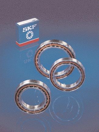
9 Angular contact ball bearings SKF produces state-of-the-art precision angular contact ball bearings for the work spindles of machine tools and similar applications where demands on running accuracy and speed capability are high or very high. SKF precision angular contact ball bearings ( fig ) are produced in three different dimension series 79, 70 and 72 and are available with contact angles of 5 (designation suffix CD) and 25 (designation suffix ACD) ( fig 2 ). To meet the various demands with regard to running accuracy, speed capability, stiffness as well as load carrying capacity placed on precision bearing arrangements in an optimum manner, three different types of single row angular contact ball bearings are available: precision angular contact ball bearings of standard design, hybrid precision angular contact ball bearings (with ceramic balls), and precision angular contact ball bearings with modified internal geometry. Precision angular contact ball bearings, standard design SKF precision angular contact ball bearings of the standard design are made of carbon chromium steel. They are available in the three bearing series with a contact angle of 5 (designation suffix CD) as well as with a contact angle of 25 (designation suffix ACD), ( fig 2 ). The bearings with the larger contact angle are used primarily where high axial stiffness or high axial load carrying capacity are required. Fig 3 on page 0 shows the different cross sections of the three bearing series with reference to the outside and bore diameters. The different space requirements of the three series are clearly apparent. Each series has typ- Fig Precision angular contact ball bearings of standard design Fig 2 Precision angular contact ball bearing for machine tool work spindles 9


10 Angular contact ball bearings Fig 3 SKF hybrid precision angular contact ball bearings are identified by the designation suffix HC, e.g. 792 CDGA/HCP4A. Comparison of the cross sections of bearings of series 79, 70 and 72 ical properties which are appropriate to different applications. Hybrid precision angular contact ball bearings SKF hybrid precision angular contact ball bearings have the same design as the standard bearings but have ceramic balls instead of steel balls ( fig 4 ). The silicon nitride ceramic material demonstrates a good combination of stiffness, hardness, wear resistance and density. The ceramic balls have 60 % lower density than steel balls so that the centrifugal forces in the bearing are much reduced. The lighter balls also cause less alteration of the contact angle and increase the dynamic accuracy of the bearing. A 70 % smaller thermal expansion than for steel balls considerably reduces the influence of temperature changes on the bearing preload. It is therefore possible for hybrid bearings to operate at speeds which are some 20 % higher than for all-steel bearings without any risk of uncontrolled preload increases occurring. The modulus of elasticity of the ceramic material is some 50 % greater than for steel. Thus hybrid bearings are stiffer, by up to 20 % at elevated speeds. Power losses are reduced by approximately 0 % compared with all-steel bearings. Fig 4 Precision angular contact ball bearings with modified internal design The majority of the high demands associated with machine tool spindle applications can be met with the standard design of precision angular contact ball bearings with steel balls or with ceramic balls. For applications where maximum speed capability and stiffness are required, however, some sizes of series 79 and 70 are also available with modified internal design. These bearings of the CE design have a contact angle of 5 and incorporate more, but smaller balls than the corresponding sizes of series 79 CD or 70 CD ( fig 5 ) except for the smallest sizes. The gyratory forces exerted by the balls on the outer ring raceways are much reduced for the small balls compared with the larger balls of the standard design and the surface pressure in the rolling contact is also reduced. By using smaller balls, it is possible for the bearing rings to be correspondingly thicker for the same envelope dimensions. This means that any inaccuracies of form of the bearing seatings on the shaft or in the housing will have less influence on the accuracy of form of the bearing rings so that the bearings will have enhanced running accuracy. The CE-design bearings are fully interchangeable with the standard CD-design bearings. The CE-design bearings are characterised by very high speed capability compared with the CD-design bearings. The bearings are available in an all-steel version, the CE design, or in a hybrid version with ceramic balls identified by the designation suffix CE/HC. They are produced as standard to tolerance class P4A specifications. Standard designs of SKF hybrid angular contact ball bearings 0


11 Fig Precision angular contact ball bearing, CE design 5 Matched bearing sets All SKF precision angular contact ball bearings can be supplied as required in complete sets of two, three or four matched bearings in the arrangements shown in fig 6. The bearings of a set are matched in production so that when they are mounted immediately adjacent to each other in the prescribed order, a given preload will be obtained or the load will be evenly distributed. The bore and outside diameters of the bearings of a set differ from each other by half the permissible diameter tolerance. The difference is even smaller for bearings to tolerance class PA9A. To facilitate correct mounting, the bearings of a set have a V marking on their outside cylindrical surface. The prescribed order must be adhered to if the set is to perform properly. The V marking also indicates how the set should be mounted in relation to the axial load. The point of the V indicates the direction in which the axial load, or where axial load acts in both directions, the greater of the axial loads, should act on the inner ring. The bearings of a set are supplied in a unit package but are individually packed within the package. Bearings for universal pairing A special execution of the SKF precision angular contact ball bearings is that for universal pairing. These bearings are matched during production so that they can be mounted immediately adjacent to each other in random order (back-to-back, face-to-face or in tandem) and will then have a light, medium or heavy preload when arranged back-to-back or face-to-face, as required. Bearings for universal pairing are identified by the designation suffix G followed by A, B or C for the preload class, e.g CDGA/P4A. When ordering it should be remembered that the number of individual bearings should be stated and not the number of pairs. Sets of two bearings for universal pairing with matched bore and outside diameters are also available. Depending on preload class, these carry the designation suffix DGA, DGB or DGC, e.g CD/P4ADGA. In this case, however, the number of pairs required must be stated, not the number of individual bearings. Fig 6 Back-to-back arrangement Designation suffix DB Face-to-face arrangement Designation suffix DF Tandem arrangement Designation suffix DT Combination of tandem and back-to-back arrangement Designation suffix TBT Combination of tandem and face-to-face arrangement Designation suffix TFT Tandem arrangement Designation suffix TT Back-to-back arrangement Designation suffix QBC Face-to-face arrangement Designation suffix QFC Possible combinations of matched bearing sets
12 Angular contact ball bearings Bearings of series 79: preload in bearings for universal pairing and bearing sets arranged back-to-back or face-toface. Hybrid bearings of the CD/HC and ACD/HC designs are only available with axial preload to classes A and B. Tabelle Table Bearing Axial preload in bearing of series 79 of designs Bore Size CD, CD/HC ACD, ACD/HC CE, CE/HC dia- Class Class Class meter A B C A B C A B mm N Dimensions The boundary dimensions of the bearings shown in the bearing tables conform to ISO 5-98, Dimension Series 9, 0 and 02. Tolerances SKF precision angular contact ball bearings are produced as standard to tolerance class P4A specifications. They may also be supplied with greater accuracy to PA9A, to order. The actual values of the tolerances for classes P4A and PA9A are given in Tables and 2, pages 67 and 68. They correspond largely to ISO 492:994 and ANSI/ABMA Std Preload To meet different requirements regarding speed capability, stiffness etc. matched sets of two precision angular contact ball bearings arranged backto-back or face-to-face are supplied in three preload classes by SKF. Class A: light preload Class B: medium preload Class C: heavy preload The magnitude of the preload depends on the series, the contact angle and the bearing size. The actual values are given in Tables to 3. The values apply to unmounted pairs arranged back-to-back and face-to-face and are nominal values. Bearing sets of three or four bearings in tandem/back-to-back or tandem/faceto-face arrangements have a higher preload than that given in Tables to 3. The actual preload can be obtained by multiplying the table values by ,35 for TBT and TFT sets 2,00 for QBC and QFC sets,60 for QBT and QFT sets 2

13 Tabelle Table Bearing Axial preload in bearings of series 70 of designs Bore Size CD, CD/HC ACD, ACD/HC CE, CE/HC dia- Class Class Class meter A B C A B C A B mm N 2 Bearings of series 70: preload in bearings for universal pairing and bearing sets arranged back-to-back or face-toface. Hybrid bearings of the CD/HC and ACD/HC designs are only available with axial preload to classes A and B Cages All SKF precision angular contact ball bearings are fitted with an outer ring centred cage ( fig 7 ) which is particularly lightweight so that gyratory forces are kept to a minimum. The cage form allows uninterrupted access of lubricant to the ball/raceway contacts. The present fabric reinforced phenolic resin cages are gradually being replaced by an even more stable cage of PEEK (polyether ether ketone). Bearings with the new PEEK cage are identified by the designation suffix TNH, e.g. 796 CDTNH/P4A. Speed ratings The speed ratings quoted in the bearing tables are guideline values and apply provided the bearings operate under light loads (P 0,06 C) and are lightly preloaded by means of springs. Heat transport away from the bearing position should also be good. The values given under oil spot lubrication are maximum values, as are those under grease lubrication; they can be attained using a good quality grease of soft consistency. The speed ratings for bearing sets can be obtained by multiplying the ratings quoted for single bearings by the reduction factors given in Table 4. Fig 7 Cage made of fabric reinforced phenolic resin 3
14 Angular contact ball bearings Bearings of series 72: preload in bearings for universal pairing and bearing sets arranged back-to-back of face-toface. Hybrid bearings of the CD/HC and ACD/HC designs are only available with axial preload to classes A and B. Bearing Axial preload in bearings of series 72 of designs Bore Size CD, CD/HC ACD, ACD/HC dia- Class Class meter A B C A B C mm N Table Reduction factors for speed ratings Table 4 Bearing arrrangement Reduction factors for preload arrangements Bearings of designs CD, CD/HC, ACD, ACD/HC, CE and CE/HC CE and CE/HC with d 50 mm with d > 50 mm and preload to class and preload to class A B C A B Set of two bearings arranged in tandem 0,90 0,80 0,65 0,90 0,70 Set of two bearings arranged back-to-back or face-to-face 0,80 0,70 0,55 0,75 0,60 Set of three bearings 0,70 0,55 0,35 0,65 0,40 Set of four bearings 0,65 0,45 0,25 0,55 0,30 4
15 Load carrying capacity of bearing sets The values given in the bearing tables for the basic dynamic and static load ratings apply to single bearings. The basic dynamic load ratings for sets of bearings in any order can be obtained by multiplying the C value for a single bearing by,62 for sets of two bearings 2,6 for sets of three bearings 2,64 for sets of four bearings. Equivalent dynamic bearing load For single row angular contact ball bearings arranged singly or paired in tandem P= F r when F a /F r e P= XF r + YF a when F a /F r > e The appropriate values for X and Y for the different contact angles will be found in Table 5. When calculating bearing pairs, F r and F a represent the forces acting on the bearing pair. Equivalent static bearing load For single row angular contact ball bearings arranged singly or paired in tandem P 0 = 0,5 F r + Y 0 F a If P 0 < F r, P 0 = F r should be used. The appropriate values for Y 0 for the different contact angles will be found in Table 5. When calculating bearing pairs, F r and F a represent the forces acting on the bearing pair. The corresponding basic static load ratings are obtained by multiplying the C 0 value for a single bearing by the number of bearings in the set (2, 3 or 4). For bearing pairs arranged back-toback or face-to-face P= F r + Y F a when F a /F r e P= XF r + Y 2 F a when F a /F r > e The appropriate values for X, Y and Y 2 for the different contact angles will be found in Table 6. When calculating bearing pairs, F r and F a represent the forces acting on the bearing pair. When calculating sets of more than two bearings arranged back-to-back or face-to-face, it is necessary to consider the number of bearings supporting the load in each direction. For bearing pairs arranged back-toback or face-to-face P 0 = F r + Y 0 F a The appropriate values for Y 0 for the different contact angles will be found in Table 6. When calculating bearing pairs, F r and F a represent the forces acting on the bearing pair. When calculating sets of more than two bearings arranged back-to-back or face-to-face, it is necessary to consider the number of bearings supporting the load in each direction. Calculation factors for single row angular contact ball bearings arranged singly or paired in tandem Calculation factors for single row angular contact ball bearing pairs arranged back-to-back or face-to-face Table 5 Table 6 f 0 F a /C 0 e X Y Y 0 2 f 0 F a /C 0 e X Y Y 2 Y 0 Contact angle 5 (designation suffix CD and CE) 0,78 0,38 0,44,47 0,46 0,357 0,40 0,44,40 0,46 0,74 0,43 0,44,30 0,46,07 0,46 0,44,23 0,46,43 0,47 0,44,9 0,46 2,4 0,50 0,44,2 0,46 3,57 0,55 0,44,02 0,46 5,35 0,56 0,44,00 0,46 Contact angle 5 (designation suffix CD and CE) 0,78 0,38 0,72,65 2,39 0,92 0,357 0,40 0,72,57 2,28 0,92 0,74 0,43 0,72,46 2, 0,92,07 0,46 0,72,38 2,00 0,92,43 0,47 0,72,34,93 0,92 2,4 0,50 0,72,26,82 0,92 3,57 0,55 0,72,4,66 0,92 5,35 0,56 0,72,2,63 0,92 Contact angle 25 (designation suffix ACD) 0,68 0,4 0,87 0,38 Contact angle 25 (designation suffix ACD ) 0,68 0,67 0,92,4 0,76 5
16 Precision angular contact ball bearings d 8 20 mm CD, ACD Principal dimensions Basic load ratings Fatigue Calcu- Speed ratings Mass Designation dynamic static load lation Lubrication limit factor grease oil spot d D B C C 0 P u f 0 mm N N r/min kg , ,0 708 CD ,0 708 ACD , , CD , ACD , , CD , ACD , , CD , ACD , , CD , ACD , , CD , ACD , , CD , ACD , , CD , ACD , , CD , ACD , , CD , ACD , , CD , ACD , , CD , ACD , , CD , ACD , , CD , ACD , , CD , ACD , , CD , ACD , , CD , ACD
17 Dimensions Abutment and fillet dimensions d d D r,2 r 3,4 a d a D a D b r a r b min min min max max max max mm mm 8 2,6 7,7 0,3 0, ,4 0,3 0, 2,6 7,5 0,3 0, ,4 0,3 0, 9 3,9 9,5 0,3 0, ,4 0,3 0, 3,9 9,2 0,3 0, ,4 0,3 0, 0 3,9 8, 0,3 0, ,8 0,3 0, 3,9 8, 0,3 0, ,8 0,3 0, 5, 2,3 0,3 0, ,4 0,3 0, 5, 2 0,3 0, ,4 0,3 0, 6,8 23,3 0,6 0, ,6 0,3 6,8 23,3 0,6 0, ,6 0,3 2 5,9 20, 0,3 0, ,8 0,3 0, 5,9 20, 0,3 0, ,8 0,3 0, 7, 23,3 0,3 0, ,4 0,3 0, 7, 23 0,3 0, ,4 0,3 0, 8,2 25,8 0,6 0, ,6 0,3 8,2 25,8 0,6 0, ,6 0,3 5 9, 23,9 0,3 0, ,8 0,3 0, 9, 23,9 0,3 0, ,8 0,3 0, 20,6 26,8 0,3 0, ,4 0,3 0, 20,6 26,5 0,3 0, ,4 0,3 0, 2,5 29, 0,6 0, ,6 0,3 2,5 29, 0,6 0, ,6 0,3 7 2, 25,9 0,3 0, ,8 0,3 0, 2, 25,9 0,3 0, ,8 0,3 0, 22,9 29,6 0,3 0, ,4 0,3 0, 22,9 29,2 0,3 0, ,4 0,3 0, 24,2 32,8 0,6 0, ,6 0,3 24,2 32,8 0,6 0, ,6 0, ,4 3,6 0,3 0, ,8 0,3 0, 25,4 3,6 0,3 0, ,8 0,3 0, 26,9 35, 0,6 0, ,6 0,3 26,9 35, 0,6 0, ,6 0,3 29, 38,7 0, ,3 29, 38,7 0, ,3 2
18 Precision angular contact ball bearings d mm CD, ACD CE Principal dimensions Basic load ratings Fatigue Calcu- Speed ratings Mass Designation dynamic static load lation Lubrication limit factor grease oil spot d D B C C 0 P u f 0 mm N N r/min kg , CD , ACD , , CD , , CE , ACD , , CD , ACD , CD , ACD , , 7006 CD , , 7006 CE , 7006 ACD , CD , ACD , CD , ACD , , CD , , CE , ACD , CD , ACD , 7908 CD , 7908 ACD , CD , , CE , ACD , CD , ACD , CD , ACD , CD , ACD , CD , ACD 3
19 Dimensions Abutment and fillet dimensions d d D r,2 r 3,4 a d a d b D a D b r a r b min min min min max max max max mm mm 25 30,4 36,6 0,3 0, ,8 0,3 0, 30,4 36,6 0,3 0, ,8 0,3 0, 3,9 40, 0,6 0, ,6 0,3 32,2 39,9 0,6 0, ,6 0,3 3,9 40, 0,6 0, ,6 0,3 34, 43,7 0, ,3 34, 43,7 0, , ,4 4,6 0,3 0, ,8 0,3 0, 35,4 4,6 0,3 0, ,8 0,3 0, 38, 46,9 0, ,3 37,7 47,3 0, ,3 38, 46,9 0, ,3 40,3 5,7 0, ,3 40,3 5,7 0, ,3 35 4,2 48,8 0,6 0, ,8 0,6 0, 4,2 48,8 0,6 0, ,8 0,6 0, 43,7 53,3 0, ,3 43,7 53,3 0, ,3 43,7 53,3 0, , , 0, , , 0, , ,7 55,3 0,6 0, ,8 0,6 0, 46,7 55,3 0,6 0, ,8 0,6 0, 49,2 58,8 0, ,3 49,2 58,8 0, ,3 49,2 58,8 0, , , 0, , , 0, , ,2 60,8 0,6 0, ,8 0,6 0, 52,2 60,8 0,6 0, ,8 0,6 0, 54,7 65,3 0, ,3 54,7 65,3 0, ,3 57,5 72,5, 0, ,6 57,5 72,5, 0, ,6 4
20 Precision angular contact ball bearings d mm CD, ACD CE Principal dimensions Basic load ratings Fatigue Calcu- Speed ratings Mass Designation dynamic static load lation Lubrication limit factor grease oil spot d D B C C 0 P u f 0 mm N N r/min kg ,3 790 CD ,3 790 ACD , CD , CE , ACD , CD , ACD ,8 79 CD ,8 79 ACD ,37 70 CD ,37 70 ACD ,6 72 CD ,6 72 ACD ,9 792 CD ,9 792 CE ,9 792 ACD , CD , CE , ACD , CD , ACD ,2 793 CD ,2 793 ACD , CD , CE , ACD , CD , ACD , CD , CE , ACD , CD , CE , ACD ,0 724 CD ,0 724 ACD 5
21 Dimensions Abutment and fillet dimensions d d D r,2 r 3,4 a d a d b D a D b r a r b min min min min max max max max mm mm 50 56,7 65,3 0,6 0, ,8 0,6 0, 56,7 65,3 0,6 0, ,8 0,6 0, 59,7 70,3 0, ,3 59,3 70,8 0, ,3 59,7 70,3 0, ,3 62,5 77,5, 0, ,6 62,5 77,5, 0, , ,7 72,3 0, ,3 62,7 72,3 0, ,3 66,3 78,7, 0, ,6 66,3 78,7, 0, , ,9,5 0, ,5 0, ,9,5 0, ,5 0, ,7 77,3 0, ,3 68,6 76,4 0, ,3 67,7 77,3 0, ,3 7,3 83,7, 0, ,6 72,7 82,3, 0, ,6 7,3 83,7, 0, ,6 75,6 94,4,5 0, ,5 0,6 75,6 94,4,5 0, ,5 0, ,7 82,3 0, ,3 72,7 82,3 0, ,3 76,3 88,7, 0, ,6 77,7 87,3, 0, ,6 76,3 88,7, 0, ,6 82,5 03,5 0, ,5 0,6 82,5 03,5 0, ,5 0, ,3 90,7 0, ,3 80,2 89,3 0, ,3 79,3 90,7 0, ,3 82,9 97,, 0, ,6 84,2 95,8, 0, ,6 82,9 97,, 0, , ,5 0, ,5 0, ,5 0, ,5 0,6 6
22 Precision angular contact ball bearings d mm CD, ACD CE Principal dimensions Basic load ratings Fatigue Calcu- Speed ratings Mass Designation dynamic static load lation Lubrication limit factor grease oil spot d D B C C 0 P u f 0 mm N N r/min kg , CD , ACD , CD , ACD , CD , ACD , CD , CE , ACD , CD , CE , ACD , CD , ACD , CD , ACD , CD , ACD , CD , ACD , CD , CE , ACD ,5 708 CD ,0 708 CE ,5 708 ACD , CD , ACD , CD , ACD , CD , ACD , CD , ACD 7
23 Dimensions Abutment and fillet dimensions d d D r,2 r 3,4 a d a d b D a D b r a r b min min min min max max max max mm mm 75 84,3 95,7 0, ,3 84,3 95,7 0, ,3 87,9 03, 0, ,6 87,9 03, 0, ,6 92 3,5 0, ,5 0,6 92 3,5 0, ,5 0, ,3 0 0, ,3 90,2 99,8 0, ,3 89,3 0 0, ,3 94,4, 0, ,6 95,8 09,2, 0, ,6 94,4, 0, ,6 98, , ,8 0, 0, ,6 95,8 0, 0, ,6 99,4 6, 0, ,6 99,4 6, 0, , , , , 0, ,6 0,7 3,3, 0, ,6 00 5, 0, , ,5 0, ,5 0,6 07,3 22,7,5 0, ,5 0, ,5 0, ,5 0, , 0, , , 0, ,6 29,5 0, ,5 0,6 29,5 0, ,5 0, ,, ,,
24 Precision angular contact ball bearings d mm CD, ACD CE Principal dimensions Basic load ratings Fatigue Calcu- Speed ratings Mass Designation dynamic static load lation Lubrication limit factor grease oil spot d D B C C 0 P u f 0 mm N N r/min kg , CD , ACD , CD , CE , ACD , CD , ACD , CD , ACD , CD , ACD , CD , ACD , CD , ACD , CD , ACD , CD , ACD , CD , ACD , CD , ACD , CD , ACD , CD , ACD , CD , ACD , CD , ACD , CD , ACD 9
25 Dimensions Abutment and fillet dimensions d d D r,2 r 3,4 a d a d b D a D b r a r b min min min min max max max max mm mm , 0, ,6 2 28, 0, ,6 6 34,5 0, ,5 0,6 7,3 32,7,5 0, ,5 0,6 6 34,5 0, ,5 0, ,, ,, , 0, ,6 7 33, 0, , ,, ,, , 0, , , 0, , ,, ,, , 0, , , 0, , ,, ,, ,5 0, ,5 0, ,5 0, ,5 0, ,5 0, ,5 0, ,5 0, ,5 0,
26 Precision angular contact ball bearings d mm CD, ACD Principal dimensions Basic load ratings Fatigue Calcu- Speed ratings Mass Designation dynamic static load lation Lubrication limit factor grease oil spot d D B C C 0 P u f 0 mm N N r/min kg , CD , ACD , CD , ACD , CD , ACD , CD , ACD , CD , ACD , CD , ACD , CD , ACD , CD , ACD , CD , ACD , CD , ACD , CD , ACD , CD , ACD , CD , ACD , CD , ACD , CD , ACD , CD , ACD
27 Dimensions Abutment and fillet dimensions d d D r,2 r 3,4 a d a D a D b r a r b min min min max max max max mm mm , , , , ,, ,, ,, ,, ,, ,, , , ,, ,, , , , , , , ,, ,, , , , ,5 2
28 Hybrid precision angular contact ball bearings d 8 20 mm CD/HC, ACD/HC Principal dimensions Basic load ratings Fatigue Calcu- Speed ratings Mass Designation dynamic static load lation Lubrication limit factor grease oil spot d D B C C 0 P u f 0 mm N N r/min kg , , CD/HC , ACD/HC , , CD/HC , ACD/HC , , CD/HC , ACD/HC , , CD/HC , ACD/HC , , CD/HC , ACD/HC , , CD/HC , ACD/HC , , CD/HC , ACD/HC , , CD/HC , ACD/HC , , CD/HC , ACD/HC , , CD/HC , ACD/HC , , CD/HC , ACD/HC , , CD/HC , ACD/HC , , CD/HC , ACD/HC , , CD/HC , ACD/HC , , CD/HC , ACD/HC , , CD/HC , ACD/HC , , CD/HC , ACD/HC 3
29 Dimensions Abutment and fillet dimensions d d D r,2 r 3,4 a d a D a D b r a r b min min min max max max max mm mm 8 2,6 7,7 0,3 0, ,4 0,3 0, 2,6 7,5 0,3 0, ,4 0,3 0, 9 3,9 9,5 0,3 0, ,4 0,3 0, 3,9 9,2 0,3 0, ,4 0,3 0, 0 3,9 8, 0,3 0, ,8 0,3 0, 3,9 8, 0,3 0, ,8 0,3 0, 5, 2,3 0,3 0, ,4 0,3 0, 5, 2 0,3 0, ,4 0,3 0, 6,8 23,3 0,6 0, ,6 0,3 6,8 23,3 0,6 0, ,6 0,3 2 5,9 20, 0,3 0, ,8 0,3 0, 5,9 20, 0,3 0, ,8 0,3 0, 7, 23,3 0,3 0, ,4 0,3 0, 7, 23 0,3 0, ,4 0,3 0, 8,2 25,8 0,6 0, ,6 0,3 8,2 25,8 0,6 0, ,6 0,3 5 9, 23,9 0,3 0, ,8 0,3 0, 9, 23,9 0,3 0, ,8 0,3 0, 20,6 26,8 0,3 0, ,4 0,3 0, 20,6 26,5 0,3 0, ,4 0,3 0, 2,5 29, 0,6 0, ,6 0,3 2,5 29, 0,6 0, ,6 0,3 7 2, 25,9 0,3 0, ,8 0,3 0, 2, 25,9 0,3 0, ,8 0,3 0, 22,9 29,6 0,3 0, ,4 0,3 0, 22,9 29,2 0,3 0, ,4 0,3 0, 24,2 32,8 0,6 0, ,6 0,3 24,2 32,8 0,6 0, ,6 0, ,4 3,6 0,3 0, ,8 0,3 0, 25,4 3,6 0,3 0, ,8 0,3 0, 26,9 35, 0,6 0, ,6 0,3 26,9 35, 0,6 0, ,6 0,3 29, 38,7 0, ,3 29, 38,7 0, ,3 4
30 Hybrid precision angular contact ball bearings d mm CD/HC, ACD/HC CE/HC Principal dimensions Basic load ratings Fatigue Calcu- Speed ratings Mass Designation dynamic static load lation Lubrication limit factor grease oil spot d D B C C 0 P u f 0 mm N N r/min kg , CD/HC , ACD/HC , , CD/HC , , CE/HC , ACD/HC , , CD/HC , ACD/HC , CD/HC , ACD/HC , , CD/HC , , CE/HC , ACD/HC , CD/HC , ACD/HC , CD/HC , ACD/HC , , CD/HC , , CE/HC , ACD/HC , CD/HC , ACD/HC , CD/HC , ACD/HC , CD/HC , , CE/HC , ACD/HC , CD/HC , ACD/HC , 7909 CD/HC , 7909 ACD/HC , CD/HC , ACD/HC , CD/HC , ACD/HC 5
31 Dimensions Abutment and fillet dimensions d d D r,2 r 3,4 a d a d b D a D b r a r b min min min min max max max max mm mm 25 30,4 36,6 0,3 0, ,8 0,3 0, 30,4 36,6 0,3 0, ,8 0,3 0, 3,9 40, 0,6 0, ,6 0,3 32,2 39,9 0,6 0, ,3 3,9 40, 0,6 0, ,6 0,3 34, 43,7 0, ,3 34, 43,7 0, , ,4 4,6 0,3 0, ,8 0,3 0, 35,4 4,6 0,3 0, ,8 0,3 0, 38, 46,9 0, ,3 37,7 47,3 0, ,3 38, 46,9 0, ,3 40,3 5,7 0, ,3 40,3 5,7 0, ,3 35 4,2 48,8 0,6 0, ,8 0,6 0, 4,2 48,8 0,6 0, ,8 0,6 0, 43,7 53,3 0, ,3 43,7 53,3 0, ,3 43,7 53,3 0, , , 0, , , 0, , ,7 55,3 0,6 0, ,8 0,6 0, 46,7 55,3 0,6 0, ,8 0,6 0, 49,2 58,8 0, ,3 49,2 58,8 0, ,3 49,2 58,8 0, , , 0, , , 0, , ,2 60,8 0,6 0, ,8 0,6 0, 52,2 60,8 0,6 0, ,8 0,6 0, 54,7 65,3 0, ,3 54,7 65,3 0, ,3 57,5 72,5, 0, ,6 57,5 72,5, 0, ,6 6
32 Hybrid precision angular contact ball bearings d mm CD/HC, ACD/HC CE/HC Principal dimensions Basic load ratings Fatigue Calcu- Speed ratings Mass Designation dynamic static load lation Lubrication limit factor grease oil spot d D B C C 0 P u f 0 mm N N r/min kg , 790 CD/HC , 790 ACD/HC ,2 700 CD/HC ,2 700 CE/HC ,2 700 ACD/HC , CD/HC , ACD/HC ,5 79 CD/HC ,5 79 ACD/HC ,3 70 CD/HC ,3 70 ACD/HC ,5 72 CD/HC ,5 72 ACD/HC ,6 792 CD/HC ,7 792 CE/HC ,6 792 ACD/HC , CD/HC , CE/HC , ACD/HC , CD/HC , ACD/HC ,7 793 CD/HC ,7 793 ACD/HC , CD/HC , CE/HC , ACD/HC , CD/HC , CE/HC , ACD/HC , CD/HC , CE/HC , ACD/HC , CD/HC , ACD/HC , CD/HC , ACD/HC 7
33 Dimensions Abutment and fillet dimensions d d D r,2 r 3,4 a d a d b D a D b r a r b min min min min max max max max mm mm 50 56,7 65,3 0,6 0, ,8 0,6 0, 56,7 65,3 0,6 0, ,8 0,6 0, 59,7 70,3 0, ,3 59,3 70,8 0, ,3 59,7 70,3 0, ,3 62,5 77,5, 0, ,6 62,5 77,5, 0, , ,7 72,3 0, ,3 62,7 72,3 0, ,3 66,3 78,7, 0, ,6 66,3 78,7, 0, , ,9,5 0, ,5 0, ,9,5 0, ,5 0, ,7 77,3 0, ,3 68,6 76,4 0, ,3 67,7 77,3 0, ,3 7,3 83,7, 0, ,6 72,7 82,3, 0, ,6 7,3 83,7, 0, ,6 75,6 94,4,5 0, ,5 0,6 75,6 94,4,5 0, ,5 0, ,7 82,3 0, ,3 72,7 82,3 0, ,3 76,3 88,7, 0, ,6 77,7 87,3, 0, ,6 76,3 88,7, 0, , ,3 90,7 0, ,3 80,2 89,3 0, ,3 79,3 90,7 0, ,3 82,9 97,, 0, ,6 84,2 95,8, 0, ,6 82,9 97,, 0, , ,3 95,7 0, ,3 84,3 95,7 0, ,3 87,9 03, 0, ,6 87,9 03, 0, ,6 8
34 Hybrid precision angular contact ball bearings d mm CD/HC, ACD/HC CE/HC Principal dimensions Basic load ratings Fatigue Calcu- Speed ratings Mass Designation dynamic static load lation Lubrication limit factor grease oil spot d D B C C 0 P u f 0 mm N N r/min kg ,3 796 CD/HC , CE/HC ,3 796 ACD/HC ,7 706 CD/HC , CE/HC ,7 706 ACD/HC , CD/HC , ACD/HC , CD/HC , ACD/HC , CD/HC , CE/HC , ACD/HC , CD/HC , CE/HC , ACD/HC , CD/HC , ACD/HC , CD/HC , ACD/HC , CD/HC , ACD/HC , CD/HC , CE/HC , ACD/HC , CD/HC , ACD/HC , CD/HC , ACD/HC , CD/HC , ACD/HC , CD/HC , ACD/HC , CD/HC , ACD/HC 9


35 Dimensions Abutment and fillet dimensions d d D r,2 r 3,4 a d a d b D a D b r a r b min min min min max max max max mm mm 80 89,3 0 0, ,3 90,2 99,8 0, ,3 89,3 0 0, ,3 94,4, 0, ,6 95,8 09,2, 0, ,6 94,4, 0, , ,8 0, 0, ,6 95,8 0, 0, ,6 99,4 6, 0, ,6 99,4 6, 0, , , 0, ,6 0,7 3,3, 0, ,6 00 5, 0, , ,5 0, ,5 0,6 07,3 22,7,5 0, ,5 0, ,5 0, ,5 0, , 0, , , 0, ,6 29,5 0, ,5 0,6 29,5 0, ,5 0, , 0, ,6 2 28, 0, ,6 6 34,5 0, ,5 0,6 7,3 32,7,5 0, ,5 0,6 6 34,5 0, ,5 0, , 0, ,6 7 33, 0, , , 0, , , 0, , , 0, , , 0, , ,5 0, ,5 0, ,5 0, ,5 0, ,5 0, ,5 0, ,5 0, ,5 0,6 20
36
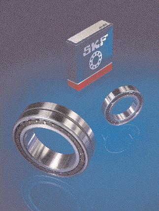
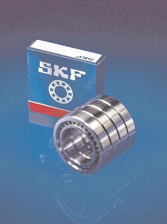
37 Cylindrical roller bearings 2 High precision cylindrical roller bearings are bearings with a low cross section, high load carrying capacity and little resilience. These properties make them particularly suitable for machine tool applications where spindle bearing arrangements are required to support heavy loads and have high stiffness. SKF produces double row as well as single row bearings. Double row cylindrical roller bearings Double row high precision cylindrical roller bearings are produced by SKF in the NN and NNU designs and in Dimension Series 30 and 49. The bearings of series NNU 49 have a particularly low cross section and give very stiff arrangements whereas those of series NN 30 have a somewhat higher cross section but can carry much heavier loads. In bearings of the NN design ( fig ) the rollers are guided between integral flanges on the inner ring and in bearings of the NNU design ( fig 2 ) between integral flanges in the outer ring. The other ring is without flanges. Axial displace-ment of the shaft relative to the housing in both directions can therefore take place, within certain limits, inside the bearings of Fig Fig 2 both designs. The bearings are separable, i.e. the ring with integral flanges and the roller and cage assem-blies can be withdrawn from the other ring. This simplifies mounting and dismounting. The bearings are produced with a cylindrical bore as well as with a tapered bore (taper :2); the bearings of series NN 30 normally have a tapered bore. Bearings with a tapered bore can be adjusted on mounting to a given radial clearance or preload. In order to facilitate efficient lubrication, bearings of series NN 30 having a bore diameter of 50 mm and above and all bearings of series NNU 49 have an annular groove and three lubrication holes in the outer ring the W33 feature. Fig Cylindrical roller bearing, NN design Fig 2 Cylindrical roller bearing, NNU design 22
 are designed for bearing arrangements where the high load carrying capacity of the double row cylindrical roller bearings is not required.")
38 Cylindrical roller bearings Fig 3 Fig 4 Cylindrical roller bearing, N design Cages for double row cylindrical roller bearings Single row cylindrical roller bearings The single row high precision cylindrical roller bearings ( fig 3 ) are designed for bearing arrangements where the high load carrying capacity of the double row cylindrical roller bearings is not required. They belong to Dimension Series 0 which has the same diameters as the NN 30 bearings. They are produced exclusively with a tapered bore (taper :2) and the series is designated N 0 K. The rollers of these single row bearings are guided between two integral flanges on the inner ring. The outer ring is without flanges. Axial displacement of the shaft relative to the housing in both directions can there-fore take place, within certain limits, inside the bearing itself. The bearings are also separable, i.e. the inner ring with integral flanges and the roller and cage assembly can be withdrawn from the outer ring. This facilitates mounting and dismounting. Cages SKF double row cylindrical roller bearings are fitted, depending on series and size with either two separate pronged cages with cover, made of polyamide 6,6 or one double pronged machined brass cage ( fig 4 ) The single row bearings of series N 0 K are fitted with the same polyamide cages as the corresponding size of series NN 30 K. The bearings fitted with polyamide cages are identified by the designation suffix TN or TN9 and can be used without reservation at the temperatures normally occurring in machine tool applications. The cage properties are also not affected by the lubricants normally used for bearings, with the exception of some synthetic oils or greases with synthetic base oils. Dimensions The boundary dimensions of the bearings shown in the tables are in accordance with ISO 5-98, Dimension Series 0, 30 and 49. Tolerances SKF high precision cylindrical roller bearings are produced to tolerance class SP specifications which were specially defined for machine tool applications. The double row bearings with tapered bore are also available to tolerance class UP specifications to special order. The actual values of the tolerances for classes SP and UP are given in Table 3 to 5, pages 69 to 7. 23
39 Internal clearance The bearings made to tolerance class SP are produced with C radial in-ternal clearance as standard, although C does not appear in the bearing designation. The rings of one bearing may not be mixed with those of other bearings as otherwise the clearance may become inadmissibly large or small. The bearings are therefore supplied in individual packages, or if this is not the case, the components of a given bearing carry the same serial number. Bearings to tolerance class SP, particularly those of series NNU 49, are also available with radial internal clearances greater than C. When ordering it is necessary to state the required clearance class, viz. The clearance limits are given in Table and are in accordance with ISO 5753:99. The SPC2 clearance range is narrower than specified by ISO for C2 and displaced to the smaller side. The values in the table apply to bearings before mounting and under zero measuring load. Equivalent dynamic bearing load For SKF high precision cylindrical roller bearings, which can only accommodate radial loads P= F r Equivalent static bearing load For SKF high precision cylindrical roller bearings, which can only accommodate radial loads Speed ratings The ratings quoted in the bearings tables are guideline values which apply provided the bearings have a maximum preload in operation of 2 µm and the associated components are made with the recommended accuracy. Where heavier preloads occur or where the associated components are less accurate, the speed ratings must be reduced. 2 SPC2 CN C3 Radial internal clearance greater than C Normal radial internal clearance Radial internal clearance greater than Normal P 0 = F r Radial internal clearance of cylindrical roller bearings Table Bore diameter Radial internal clearance Bearings with cylindrical bore Bearings with tapered bore d C SPC2 Normal C3 C SPC2 over incl. min max min max min max min max min max min max mm µm µm
40 Cylindrical roller bearings, double row d mm NN 30 NN 30 KTN/W33 NNU 49 B/W33 NNU 49 BK/W33 Principal dimensions Basic load ratings Fatigue Speed ratings Mass Designation dynamic static load Lubrication limit grease oil spot d D B C C 0 P u mm N N r/min kg ,2 NN 3005 K ,9 NN ,9 NN 3006 KTN ,25 NN ,25 NN 3007 K ,30 NN 3008 TN ,30 NN 3008 KTN ,38 NN 3009 TN ,38 NN 3009 KTN ,42 NN 300 TN/W ,42 NN 300 KTN/W ,62 NN 30 TN/W ,62 NN 30 KTN/W ,66 NN 302 TN/W ,66 NN 302 KTN/W ,7 NN 303 TN/W ,7 NN 303 KTN/W ,00 NN 304 TN/W ,00 NN 304 KTN/W ,0 NN 305 TN/W ,0 NN 305 KTN/W ,45 NN 306 TN/W ,50 NN 306 KTN/W ,60 NN 307 TN9/W ,55 NN 307 KTN9/W ,00 NN 308 TN9/W ,95 NN 308 KTN9/W ,0 NN 309 TN9/W ,05 NN 309 KTN9/W ,90 NNU 4920 B/W ,80 NNU 4920 BK/W ,20 NN 3020 TN9/W ,0 NN 3020 KTN9/W33 25
41 2 Dimensions Abutment and fillet dimensions d d, D E, F b K r,2 s d a d a d b D a D a r a min min max min max min max mm mm 25 33,3 4,3 0,6, , ,7 48,5, ,7 48,5, ,4 55, ,4 55, ,6 6, ,6 6, ,3 67, ,3 67, ,3 72,5 3, ,3 72,5 3, ,2 8 3,7 2, 2 6,5 83, ,2 8 3,7 2, 2 6,5 83, ,3 86, 3,7 2, 2 66,5 88, ,3 86, 3,7 2, 2 66,5 88, ,2 9 3,7 2, 2 7,5 93, ,2 9 3,7 2, 2 7,5 93, ,6 00 5,5 3, 2,5 76,5 03,5 0 85,6 00 5,5 3, 2,5 76,5 03, ,6 05 5,5 3, 2,5 8,5 08, ,6 05 5,5 3, 2,5 8,5 08, ,5 3, 3 86,5 8, ,5 3, 3 86,5 8, ,5 3, 2,5 9,5 23, ,5 3, 2,5 9,5 23, ,5 3,5 2, , ,5 3,5 2, , ,5 3,5 2, , ,5 3,5 2, , ,5 3,,7 06,5 6 33, ,5 3,,7 06,5 6 33, ,5 3,5 2, , ,5 3,5 2, ,5 26
42 Cylindrical roller bearings, double row d mm NN 30 KTN9/W33 NN 30 K/W33 NNU 49 B/W33 NNU 49 BK/W33 Principal dimensions Basic load ratings Fatigue Speed ratings Mass Designation dynamic static load Lubrication limit grease oil spot d D B C C 0 P u mm N N r/min kg ,00 NNU 492 B/W ,90 NNU 492 BK/W ,70 NN 302 KTN9/W ,05 NNU 4922 B/W ,95 NNU 4922 BK/W ,40 NN 3022 KTN9/W ,80 NNU 4924 B/W ,65 NNU 4924 BK/W ,70 NN 3024 KTN9/W ,85 NNU 4926 B/W ,65 NNU 4926 BK/W ,55 NN 3026 KTN9/W ,0 NNU 4928 B/W ,90 NNU 4928 BK/W ,00 NN 3028 K/W ,25 NNU 4930 B/W ,5 NNU 4930 BK/W ,30 NN 3030 K/W ,60 NNU 4932 B/W ,30 NNU 4932 BK/W ,80 NN 3032 K/W ,95 NNU 4934 B/W ,65 NNU 4934 BK/W ,0 NN 3034 K/W ,5 NNU 4936 B/W ,0 NNU 4936 BK/W ,0 NN 3036 K/W ,0 NNU 4938 B/W ,5 NNU 4938 BK/W ,0 NN 3038 K/W ,0 NNU 4940 B/W ,5 NNU 4940 BK/W ,0 NN 3040 K/W ,5 NNU 4944 B/W ,0 NNU 4944 BK/W ,5 NN 3044 K/W33 27
43 2 Dimensions Abutment and fillet dimensions d d, D E, F b K r,2 s d a d a d b D a D a r a min min max min max min max mm mm ,5 3,,7, , ,5 3,,7, , ,5 3 2, ,5 3,,7 6, , ,5 3,,7 6, , , , ,5 5,5 3,,7 26, ,5 5 34,5 5,5 3,,7 26, , , , ,5 3,5 2, , ,5 3,5 2, , ,3 4,5, 3, ,5 3,5 2, , ,5 3,5 2, , ,3 4,5 2 3, ,5 5, ,5 5, ,3 4,5 2, ,5 5, ,5 5, ,3 4,5 2, ,5 5, ,5 5, ,3 4,5 2, ,3 4,5 2, ,3 4,5 2, , 6 2, ,3 4,5 2, ,3 4,5 2, , 6 2, , 6 2, 3, , 6 2, 3, , 6 2, 6, , 6 2, 3, , 6 2, 3, ,9 7,5 3 7, ,5 28
44 Cylindrical roller bearings, double row d mm NN 30 K/W33 NN 30 K/W33 NNU 49 B/W33 NNU 49 BK/W33 Principal dimensions Basic load ratings Fatigue Speed ratings Mass Designation dynamic static load Lubrication limit grease oil spot d D B C C 0 P u mm N N r/min kg ,5 NNU 4948 B/W ,5 NNU 4948 BK/W ,5 NN 3048 K/W ,5 NNU 4952 B/W ,5 NNU 4952 BK/W ,5 NNU 4956 B/W ,5 NNU 4956 BK/W ,0 NNU 4960 B/W ,5 NNU 4960 BK/W33 29


45 2 Dimensions Abutment and fillet dimensions d d, D E, F b K r,2 s d a d a d b D a D a r a min min max min max min max mm mm , 6 2, 3, , 6 2, 3, ,9 7,5 3 7, , ,9 7,5 2, 4, ,9 7,5 2, 4, ,9 7,5 2, 4, ,9 7,5 2, 4, , , , , , ,5 30
46 Cylindrical roller bearings, single row d 50 0 mm Principal dimensions Basic load ratings Fatigue Speed ratings Mass Designation dynamic static load Lubrications limit grease oil spot d D B C C 0 P u mm N N r/min kg ,26 N 00 KTN ,44 N 03 KTN ,62 N 04 KTN ,89 N 06 KTN ,93 N 07 KTN ,25 N 09 KTN ,30 N 020 KTN ,05 N 022 KTN9 3
47 2 Dimensions Abutment and fillet dimensions d d E r,2 r 3,4 s d a d a D a D a r a min min min max min max max mm mm 50 6,3 72,5 0, ,2 9, 0,6 3 7, , ,6 00, 0,6 3,5 76, , , 0,6 3,5 86, , , 0,6 3,5 9, , , , , ,
48

49 Single direction angular contact thrust ball bearings The single direction angular contact thrust ball bearings (screw support bearings) were specially developed for the support of ball and roller screws in machine tool applications, but can be used successfully in other applications. The bearings are characterised by high axial stiffness, high running accuracy and low friction torque. Back-to-back arrangement Designation suffix DB Combination of tandem and back-to-back arrangement Designation suffix TBT Back-to-back arrangement Designation suffix QBC Face-to-face arrangement Designation suffix DF Combination of tandem and face-to-face arrangement Designation suffix TFT Face-to-face arrangement Designation suffix QFC Fig Tandem arrangement Designation suffix DT Tandem arrangement Designation suffix TT Tandem arrangement Designation suffix QT SKF single direction angular contact thrust ball bearings are non-separable. The particularly close conformity of the raceways to the balls and the contact angle of 60 contribute to the necessary high axial stiffness and high axial load carrying capacity. Single direction angular contact thrust ball bearings can only accept axial loads acting in one direction and must therefore be adjusted against a second bearing which provides location in the opposite direction. To meet all the demands for different bearing arrangements, these bearings can be supplied singly for universal mounting or in matched sets. Bearing sets are used when the load carrying capacity of a single bearing is inadequate and/or when the bearing arrangement is required to take up axial loads acting in both directions. Matched bearing sets SKF single direction angular contact ball bearings can be supplied in matched sets of two, three or four bearings. The possible combinations are shown in fig. The sets of bearings are matched during production so that when mounted immediately adjacent to each other, the predetermined value of the preload and/or an even distribution of the load will be obtained. The bore and outside diameters of the bearings of a set differ at the most by half the permissible tolerance range. To ensure that the bearings of a set are mounted in the right order, the outside cylindrical surfaces are marked with a V. The matched bearing sets are supplied as packaged units, each bearing of the set being individually packed within the unit package. 3 Combination of tandem and back-to-back arrangement Designation suffix QBT Combination of tandem and face-to-face arrangement Designation suffix QFT Possible combinations of matched bearing sets 34

50 Single direction angular contact thrust ball bearings Bearings for universal mounting A special design of the single direction angular contact thrust ball bearings is available for universal mounting in sets. These bearings are produced so that they can be mounted immediately adjacent to each other in random order. When mounted in a back-to-back or face-to-face arrangement, the bearings will have a suitable preload. Bearings for universal pairing are identified by the suffix G followed by A or B to indicate the preload class, e.g. BSD 2047 C/GA. When ordering, it is necessary to state the number of individual bearings required and not the number of sets. Sets of two bearings for universal pairing which have matched bore and outside diameters are also available. These bearings are identified by the designation suffix DGA or DGB, depending on preload class, e.g. BSD 2047 C/DGB. Here it is necessary to state the number of sets required when ordering, not the number of individual bearings. Cartridge units In order to simplify still further the arrangement and mounting of screw support bearings, cartridge units consisting of SKF single direction angular contact ball bearings filled with grease and mounted in a flanged housing are also available ( fig 2 ). There is a choice of units with two bearings, or two bearing pairs in tandem, arranged back-toback or face-to-face. Further details will be supplied on request. Fig 2 Cages SKF single direction angular contact thrust ball bearings are fitted with a ball-centred cage of glass fibre rein-forced polyamide 6,6. Dimensions The boundary dimensions of SKF single row angular contact thrust ball bearings of series BSA 2 and BSA 3 follow the Dimension Plan for radial bearings in ISO The dimensions of bearings of series BSD and BDAB are not standardised. Tolerances SKF single direction angular contact thrust ball bearings are made to the tolerances shown in Table 6 on page 72. The dimensional accuracy corresponds to ISO 492:994 class 4, whilst the running accuracy is according to ANSI/ABMA Std , although these standards apply to radial bearings. The values given in the table apply to single bearings. The axial runout (lateral eccentricity) of a single direction angular contact thrust ball bearing is an important parameter. For matched sets which are correctly mounted on accurately ma-chined seatings, the axial runout will generally not exceed 2,5 µm. Preload All bearing sets of two bearings ar-ranged back-to-back or face-to-face are available with preload to class A and class B ( Table ). The values given in the table refer to unmounted bearing pairs, i.e. the bearing rings are free to expand. This means that after mounting the preload will increase, the increase being greater, the tighter the fit applied. Matched sets of 3 and 4 bearings arranged back-to-back or face-to-face have a higher preload. The appropriate values can be obtained by multiplying the values given in the table by Axial stiffness Single direction angular contact thrust ball bearings are designed for high stiffness. The actual values are given in Table and apply to bearing sets of two bearings arranged back-to-back or face-to-face. Matched sets of 3 and 4 bearings arranged back-to-back or face-to-face have a higher axial stiffness. The appropriate values can be obtained by multiplying the values given in the table by,45 for TBT and TFT sets,80 for QBT and QFT sets 2,00 for QBC and QFC sets Friction torque SKF single direction angular contact thrust ball bearings have low friction. The actual values for the torque are given in Table and are valid for unmounted bearing sets of two bearings. Matched sets of 3 and 4 bearings arranged back-to-back or face-to-face have a higher friction torque. The appropriate values can be obtained by multiplying the values given in the table by,35 for TBT and TFT sets,55 for QBT and QFT sets 2,00 for QBC and QFC sets Speed ratings The speed ratings given in the bearing tables are guideline values and apply to single bearings. Speed ratings for matched sets of 2, 3 or 4 bearings are obtained by mutliplying the values given in the table by 0,8 for sets of 2 bearings 0,65 for sets of 3 bearings 0,5 for sets of 4 bearings,35 for TBT and TFT sets,60 for QBT and QFT sets 2,00 for QBC and QFC sets Cartridge unit with four single direction angular contact thrust ball bearings 35
51 Preload, axial stiffness and friction torque Equivalent dynamic bearing load The equivalent dynamic bearing load for single bearings and bearing sets can be calculated separately for the two directions of axial load from P= YF a + XF r where F a /F r 2,7 P= F a + 0,92 F r where F a /F r > 2,7 When calculating F a, the preload force acting on the bearing set must be taken into account. The calculation factors X and Y can be obtained from Table 2. Equivalent static bearing load For bearing sets with bearings arranged back-to-back or face-to-face, the equivalent static bearing load can be calculated separately for each direction of axial load from Designation Preload Axial stiffness Friction torque class class class A B A B A B N N/µm Nm BSA 20 C ,06 0,029 BSA 202 C ,023 0,040 BSA 204 C ,056 0,00 BSA 205 C ,077 0,32 BSA 206 C ,30 0,225 BSA 207 C ,200 0,345 BSA 305 C ,20 0,25 BSA 306 C ,94 0,345 BSA 307 C ,290 0,523 BSD 547 C ,056 0,00 BSD 2047 C ,056 0,00 BSD 2562 C ,20 0,25 BSD 3062 C ,30 0,224 BSD 3572 C ,200 0,345 BSD 5500 C ,550 0,970 BDAB C ,056 0,00 BDAB C ,20 0,25 BDAB C ,255 0,45 Table 3 P 0 = F a + 4 F r The equation is also valid for single bearings and sets of bearings arranged in tandem provided the ratio F r /F a does not exceed 0,25 and gives satisfactory but less accurate values when F r /F a is greater than 0,25 but does not exceed 0,4. Load carrying capacity of bearing sets The values of the basic dynamic and static load ratings given in the bearing tables relate to single bearings. For sets of bearings it must be remembered that each bearing can only support axial loads acting in one direction. It is therefore necessary to calculate using only the number of bearings supporting the load in a given direction, i.e. for a pair of bearings arranged back-to-back, only one bearing will carry the load in a given direction. Appropriate guidance for the calculation of the basic dynamic and static load ratings of matched bearing sets is given in the Table 2. The arrows indicate the direction of the load acting on the outer rings. No. of bearings Load carrying capacity Calculation and of bearing set factors arrangement dynamic static X Y 2 DB C C 0,9 0,55 DF C C 0,9 0,55 DT,63 C 2 C 0 3 TBT C C 0,43 0,76,63 C 2 C 0 2,32 0,35 TFT C C 0,43 0,76,63 C 2 C 0 2,32 0,35 TT 2,6 C 3 C 0 4 QBT C C 0,7 0,88 2,6 C 3 C 0 2,52 0,26 QFT C C 0,7 0,88 2,6 C 3 C 0 2,52 0,26 QBC,63 C 2 C 0,9 0,55 QFC,63 C 2 C 0,9 0,55 QT 2,64 C 4 C 0 Table 2 36 Calculation factors for bearing sets
52 Angular contact thrust ball bearing, single direction d 2 55 mm Principal dimensions Basic load ratings Fatigue Maximum Speed ratings Mass Designation dynamic static load axial Lubrication limit load grease oil spot d D H C C 0 P u mm N N N r/min kg ,024 BSA 20 C ,054 BSA 202 C ,5 BSD 547 C ,3 BSA 204 C ,3 BSD 2047 C 47 5, ,4 BDAB C 23,838 6,999 5, ,26 BDAB C ,5 BSA 205 C ,25 BSD 2562 C ,27 BSA 305 C ,24 BSA 206 C ,22 BSD 3062 C ,4 BSA 306 C ,30 BSD 3572 C ,34 BSA 207 C ,56 BSA 307 C ,30 BSD 4072 C ,64 BSD 4090 C 44,475 76,2 5, ,3 BDAB C ,80 BSD 4500 C ,80 BSD 5000 C ,70 BSD 5500 C 37


53 3 Dimensions Abutment and fillet dimensions d d d 2 D D 2 r,2 a d a D a r a min min max max mm mm ,2 27, 22,7 0, , ,2 30, 24,8 0, ,6 29,2 34,7 4, 34, , ,2 34,7 4, 34, , ,2 34,7 4, 34, , ,2 34,7 4, 34, , ,838 39,4 46,2 54,2 45,6, 47 32, ,2 38,7 45, 38, ,4 46,2 54,2 45,6, ,4 46,2 54,2 45,6, ,2 54,4 46, ,5 4 47,2 54,4 46, ,5 43,3 5,7 6,2 5,, , ,4 55,2 63, 54,6, 55 43, ,4 55,2 63, 54,6, 56 43, ,9 58,7 69,8 58,,5 6 46,5 7,5, ,4 55,2 63, 54,6, 55 47,4 65,3 56,9 66,7 77,8 66,,5 69 5,5 8,4,5 44, ,2 67,4 59,6, , ,5 76,7 89,4 76,, , 90,5, ,5 76,7 89,4 76,, , 90,5, ,5 76,7 89,4 76,, ,5 90,5,5 38
54


 and the high-speed design of series BT")
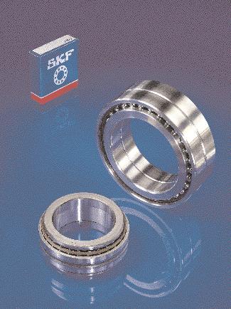
55 Double direction angular contact thrust ball bearings Double direction angular contact thrust ball bearings were developed many years ago by SKF. They are used to axially locate a spindle in both directions and are intended for use together with cylindrical roller bearings of series NN 30 K and N 0 K. Double direction angular contact thrust ball bearings have the same bore and outside diameters as the cylindrical roller bearings of series NN 30 K and N 0 K. The outside diameter of the housing washer is, however, made to tolerances such that sufficient radial clearance will be obtained to the hous-ing bore seating, which is common to the thrust bearing and the cylindrical roller bearing. The machining of the housing bore is also simplified. Two designs of SKF double direction angular contact thrust ball bearings are available: the standard design of series 2344(00) and the high-speed design of series BTM.. A and BTM.. B. Standard bearings, series 2344(00) The bearings of series 2344(00) are separable and have a one-piece housing washer, two ball and cage thrust assemblies and two shaft washers, separated by a spacer sleeve ( fig ) so dimensioned that after mounting the bearings will be preloaded. The contact angle of 60, the preload and the large number of balls in each row give the bearings high axial stiffness and enable them to operate at relatively high speeds. To ensure efficient lubrication, all bearings have an annular groove and three lubrication holes in the housing washer. High-speed bearings, BTM design The SKF high-speed bearings of the BTM design ( fig 2 ) are a new development and replace the bearings of the BTA design which are no longer 4 Fig Fig 2 Fig Double direction angular contact thrust ball bearing, series 2344(00) 40 Fig 2 Double direction angular contact thrust ball bearing, series BTM.. A
 bearings but they are 25 % narrower.")
56 Double direction angular contact thrust ball bearings produced. Their design is essentially that of two matched single row angular contact ball bearings arranged back-toback. The contact angle is 40 for series BTM.. B and 30 for series BTM.. A. The bore and outside diameters of both series are the same as those of series 2344(00) bearings but they are 25 % narrower. They are of simple design so that mounting is easy. Because the contact angle of the BTM-design bearings is less steep than that of the 2344(00) series bearings they are not as axially stiff and cannot carry such heavy axial loads but they are able to operate at 2 and almost 30 % higher speeds, respectively. As both the standard and highspeed bearings are intended to carry axial loads exclusively, the load ratings quoted in the bearing table are for axial loads, although the high-speed bearings with their contact angles of 40 and 30 are, by ISO definition, radial bearings. The high permissible operating speeds make the BTM-design bearings eminently suitable for CNC lathes and milling machines where the requisite high radial stiffness of the high-speed spindles calls for the use of cylindrical roller bearings and where the speeds exceed the capability of the 2344(00) series bearings. The SKF range of high-speed bearings covers five sizes of each series having bore diameters of 80 to 30 mm, inclusive, to cover the most common spindle diameters. Dimensions The dimensions of these double direction angular contact thrust ball bearings are not standardised but have won general acceptance. However, the bore and outside diameters conform to those of Diameter Series 0 for radial bearings according to ISO Tolerances SKF double direction angular contact thrust ball bearings meet the same high demands with respect to dimensional and running accuracy as the cylindrical roller bearings of series NN 30 K and N 0 K. Bearings of series 2344(00) are produced as standard to tolerance class SP specifications, but may, to special order, also be produced with class UP tolerances. The high-speed bearings of the BTM design are produced to tolerance class P4C specifications. The actual tolerance values for classes P4C, SP and UP will be found in Tables 7 to 9 on pages 72 and 73. Preload SKF double direction angular contact thrust ball bearings are supplied with a preload as specified in Tables and 2. The values quoted in the table apply to bearings before mounting. When mounted, the bearings may have a higher preload, depending on the shaft tolerance selected. Speed ratings The speed ratings quoted in the bearing tables for BTM bearings apply to bearings with class A preload, where the load is light (P 0,06 C) and heat transfer from the bearing position is good. The values quoted for oil spot lubrication are maximum ratings which must be reduced for other methods of oil lubrication. For heavily loaded bearings with class B preload the values should be reduced; they should be multiplied with the factor 0,55. Cages SKF double direction angular contact thrust ball bearings are fitted with two ball centred cages. Depending on series and size, the cages may be either of machined brass or heat stabilised, glass fibre reinforced polyamide 6,6 ( fig 3 ). Bearings of series 2344(00) fitted with polyamide cages are identified by the designation suffix TN or TN9. The BTM-design bearings are fitted exclusively with polyamide cages so that there is no extra TN or TN9 suffix in the designation. Bearings with polyamide 6,6 cages can be used at operating temperatures up to +20 C. The cage properties are not affected by the lubricants normally used for bearings with the exception of some synthetic oils and greases with a synthetic oil base. Equivalent dynamic bearing load For double direction angular contact Cages for double direction angular contact thrust ball bearings thrust ball bearings subjected to axial load only P= F a Equivalent static bearing load For double direction angular contact thrust ball bearings subjected to axial load only P 0 = F a Fig Mounting instructions When mounting double direction angular contact thrust ball bearings care should be taken not to mix the components of one bearing with those of other bearings. When mounting bearings of series 2344(00) care should also be taken not to apply too much axial force as otherwise the spacer sleeve may be deformed and excessive axial preload may result which would cause a rise in running temperature and would shorten bearing life. Suitable values for the axial force (in Newton) to be applied lie between 80 and 200 d (d = bearing bore diameter in mm). 3 4
 Table 2 SKF spindle unit of the MSUP design with standard")

57 Table Fig 4 Bore Axial Bore Axial dia- pre- dia- premeter load meter load mm N mm N Axial preload in double direction angular contact thrust ball bearings, series 2344(00) Table 2 SKF spindle unit of the MSUP design with standard bearing arrangement Two double row cylindrical roller bearings of series NN 30 K and one double direction angular contact thrust ball bearing of series 2344(00) Fig 5 Bore Axial preload dia- BTM.. A BTM.. B meter Preload class Preload class DBA DBB DBA DBB mm N N Axial preload in double direction angular contact thrust ball bearings, series BTM.. A and BTM.. B Classic spindle bearing arrangement with two double row cylindrical roller bearings of series NN 30 K and one double direction angular contact thrust ball bearing of the BTM design for high machining performance 42
58 Angular contact thrust ball bearings, double direction d mm 2344(00) BTM.. B BTM.. A Principal dimensions Basic load ratings Fatigue Speed ratings Mass Designation dynamic static load Lubrication limit grease oil spot d D H C C 0 P u mm N N r/min kg , BM , BM , BM , BM , TN , TN , TN , BM , ,60 BTM 80 A/DBA 25 40, ,60 BTM 80 B/DBA , TN , TN ,30 BTM 90 A/DBA ,30 BTM 90 B/DBA , TN , BM ,40 BTM 00 A/DBA ,40 BTM 00 B/DBA , TN , BM , BM ,35 BTM 20 A/DBA ,35 BTM 20 B/DBA , TN ,25 BTM 30 A/DBA ,25 BTM 30 B/DBA , TN , BM , BM , BM , BM 43

59 Dimensions Abutment and fillet dimensions 4 d d C, D K b r,2 r 3,4 d a D a r a r b min min min min max max mm mm , ,5 0, , ,5 0, , ,5 0, , ,5, 0, , ,5, 0, , ,5, 0, , ,5, 0, , ,5, 0, , , 0, ,6 00 5, 0, , ,5 8,3, 0, , ,5 8,3, 0, , ,5 0,6 0 3,5 0,6 3 29,5 0,6 0 3,5 0, ,5 8,3,5 0, ,5 0, ,5 8,3,5 0,3 4 37,5 0, ,5 0,6 07 4,5 0, ,5 0,6 07 4,5 0, ,5 8,3,5 0,3 9 42,5 0, ,5 8,3 2 0, , ,5 8,3 2 0, , ,5 8,3 2 0, , , , , 2 0, , , 2, 0, , ,5 3,9 2, 0, , ,5 3,9 2, 0, , ,5 3,9 2, 0, ,6

60 Angular contact thrust ball bearings, double direction d mm Principal dimensions Basic load ratings Fatigue Speed ratings Mass Designation dynamic static load Lubrication limit grease oil spot d D H C C 0 P u mm N N r/min kg , BM , BM , BM 45
61 Dimensions Abutment and fillet dimensions 4 d d C K b r,2 r 3,4 d a D a r a r b min min min min max max mm mm ,7 2, 0, , ,7 2, 0, , ,7 2, 0, ,6 46
62
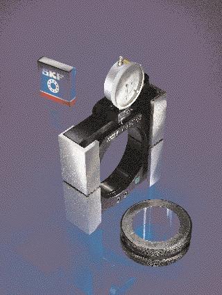
63 Gauges Conventional measuring methods and instruments are not entirely satisfactory for checking tapered journals or the radial internal clearance of cylindrical roller bearings. SKF has therefore developed a range of gauges especially to suit the requirements of rolling bearing applications, although they are equally useful for other applications. 48 Ring gauges SKF GRA 30 ring gauges are practical aids for checking the tapered shaft seatings for bearings of series NN 30 K, which are commonly used for machine tool applications. The gauges can also be used to check the shaft seatings for bearings of series N 0 K as well as those for series NNU 49 K; the width of the latter series differs only slightly from that of series NN 30 K. SKF ring gauges are available for tapered seatings having diameters up to and including 200 mm ( Product table on page 64). The gauging or reference face of ring gauges of series GRA 30 is at the large end of the bore and is used to determine the position of the tapered seating relative to a reference surface on the shaft. This reference surface may be either in front of, or behind the gauging face of the ring gauge. Where there is a free choice of dimensions it should be remembered that the reference length B c should always be longer than the dimension B b, the width of the intermediate ring, by an amount corresponding to the difference B c B b, as the bearing will be driven up further on the seating than the ring gauge when the bearing is being mounted. The final value of dimension B b is determined during mounting, taking into account the desired bearing radial internal clearance. Ring gauges can also be used to check whether the reference surface of the shaft shoulder is at right angles to the centreline of the tapered seating, as well as for checking the position and diameter of the seating. This is done by measuring the distance between the gauging surface of the ring gauge and the reference surface of the shaft using end measures. Errors of form of the taper are checked using marking blue. Internal clearance gauges SKF gauges of series GB 30 are available for use with double row cylindrical roller bearings NN 3006 K to NN 3040 K, inclusive. They may also be used for the single row cylindrical roller bearings of series N 0 K. SKF GB gauges are made in two different designs depending on size. The one design is that of gauges GB 3006 to GB 3020, inclusive. These can be used to measure the circumscribed diameter, i.e. the diameter over the rollers when they are in contact with the inner ring raceway, to an accuracy of µm. The larger gauges GB 302 to GB 3040, inclusive, have a measuring accuracy of 2 µm. The body of the gauges up to and including GB 3020 is in two parts, that of the larger gauges is slotted. The body of the gauges has two diametrically opposed gauging zones which are ground on its bore diameter surface. The body can be expanded by means of an adjustable screw. This enables the gauge to be pushed over the inner ring with roller and cage assembly without damaging the rollers and gauging surfaces. The measuring ring which is screwed to one half of the gauging ring transmits the diameter measured by both halves of the gauging ring to the indicator dial. Measuring Using a bore gauge, the raceway of the mounted outer ring is measured, and the recorded dimension trans-ferred to the centres of the gauging zones, taking into consideration the desired radial internal clearance or preload. The indicator of the GB 30 gauge is then set to zero. The inner ring with roller and cage assembly is pushed up on to its tapered journal and driven up until the indicator of the pre-set gauge again shows zero when the gauge is placed in position around the bearing set. 5

64 Ring gauges, series GRA 30 d mm Taper : 2 Bearing Bearing seating Ring gauge Designation Dimensions Dimensions Mass Designation d a d b B b B c B d d d B Nominal Tolerance mm mm kg NN 3005 K 25, ,2 ±0, ,3 GRA 3005 NN 3006 K 30, ,2 ±0, ,8 GRA 3006 NN 3007 K 35, ,2 ±0, ,2 GRA 3007 NN 3008 K 40, ,2 ±0, ,26 GRA 3008 NN 3009 K 45, ,2 ±0, ,3 GRA 3009 NN 300 K 50, ,2 ±0, ,34 GRA 300 NN 30 K 55, ,3 ±0,2 32, ,42 GRA 30 NN 302 K 60, ,3 ±0,2 34, ,45 GRA 302 NN 303 K 65, ,3 ±0,2 34, ,5 GRA 303 NN 304 K 70, ,3 ±0,2 38, ,69 GRA 304 NN 305 K 75, ,3 ±0,2 38, ,73 GRA 305 NN 306 K 80, ,3 ±0,2 44, ,88 GRA 306 NN 307 K 85, ,4 ±0, ,00 GRA 307 NN 308 K 90, ,4 ±0, ,30 GRA 308 NN 309 K 95, ,4 ±0, ,55 GRA 309 NN 3020 K 00, ,4 ±0, ,70 GRA 3020 NN 302 K 05, ,4 ±0, ,0 GRA 302 NN 3022 K 0, ,5 ±0,5 54, ,60 GRA 3022 NN 3024 K 20, ,5 ±0,5 58, ,05 GRA 3024 NN 3026 K 30, ,5 ±0,5 64, ,95 GRA 3026 NN 3028 K 40, ,6 ±0, ,75 GRA 3028 NN 3030 K 50, ,6 ±0, ,60 GRA 3030 NN 3032 K 60, ,6 ±0, ,80 GRA 3032 NN 3034 K 70, ,6 ±0, ,80 GRA 3034 NN 3036 K 80, ,7 ±0,5 90, ,5 GRA 3036 NN 3038 K 90, ,7 ±0,8 9, ,0 GRA 3038 NN 3040 K 200, ,7 ±0,8 98, ,0 GRA


65 Internal clearance gauges, series GB 30 GB 3006 GB 3020 GB 302 GB 3040 Bearing Internal clearance gauge Designation Dimensions Mass Designation L H A mm kg NN 3006 K ,00 GB 3006 NN 3007 K ,00 GB NN 3008 K ,00 GB 3008 NN 3009 K ,50 GB 3009 NN 300 K ,50 GB 300 NN 30 K ,50 GB 30 NN 302 K ,00 GB 302 NN 303 K ,00 GB 303 NN 304 K ,00 GB 304 NN 305 K ,00 GB 305 NN 306 K ,00 GB 306 NN 307 K ,50 GB 307 NN 308 K ,00 GB 308 NN 309 K ,00 GB 309 NN 3020 K ,00 GB 3020 NN 302 K ,5 GB 302 NN 3022 K ,0 GB 3022 NN 3024 K ,0 GB 3024 NN 3026 K ,0 GB 3026 NN 3028 K ,5 GB 3028 NN 3030 K ,0 GB 3030 NN 3032 K ,0 GB 3032 NN 3034 K ,0 GB 3034 NN 3036 K ,5 GB 3036 NN 3038 K ,0 GB 3038 NN 3040 K ,0 GB
66 Tolerances The dimensional and running accuracy of rolling bearings has been standardised internationally. In addition to the Normal tolerances which are adequate for the majority of bearing applications, the ISO standards cover closer tolerances, e.g. tolerance classes 6 and 5. For precision bearings, which are primarily used for machine tool spindles of all types, even greater accuracy is required. SKF precision bearings are therefore produced to the following tolerance class specifications, depending on the type of bearing and the most usual applications. The actual values are given in Tables to 9. The tolerance classes are as follows. P4A and PA9A for radial angular contact ball bearings SP and UP for radial cylindrical roller bearings P4/P2 for single direction angular contact thrust ball bearings P4C for double direction angular contact thrust ball bearings of the BTM design SP and UP for double direction angular contact thrust ball bearings of series 2344(00) The actual values correspond, or are closer than those specified in DIN 620-2:988 and DIN 620-3:982 ISO 492:994 and. ISO 99:979 ANSI/AFBMA Standard The tolerance symbols used in the tolerance tables are explained in the following. d d mp d s dmp nominal bore diameter mean bore diameter; arithmetical mean of the largest and smallest single bore diameters in one plane single bore diameter deviation of the mean bore diameter from the nominal d2mp deviation of the mean bore diameter at the theoretical small end of a tapered bore from the nominal d3mp deviation of the mean bore diameter at the theoretical large end of a tapered bore from the nominal ds V dp V dmp D D mp D s Dmp Ds V Dp V Dmp deviation of a single bore diameter from the nominal bore diameter variation; difference between the largest and smallest single bore diameters in one plane mean bore diameter variation; difference between the largest and smallest single bore diameters in one plane nominal outside diameter mean outside diameter; arithmetical mean of the largest and smallest single outside diameters in one plane single outside diameter deviation of the mean outside diameter from the nominal deviation of a single outside diameter from the nominal outside diameter variation; difference between the largest and smallest single outside diameters in one plane mean outside diameter variation; difference between the largest and smallest mean bore diameters of one ring or washer B s, C s single width of inner ring and outer ring, respectively B s, C s Bs, Cs single width of inner ring and outer ring, respectively, of a bearing specially manufactured for paired mounting deviation of single inner ring width or single outer ring width from the nominal Bs, Cs deviation of single inner ring width or single outer ring width from the nominal of a bearing specially manufactured for paired mounting V Bs, V Cs Ts K ia, K ea S d S D S ia, S ea S i, S e ring width variation; difference between the largest and smallest single widths of inner ring and of outer ring, respectively deviation of single height of thrust bearing from the nominal radial runout of assembled bearing inner ring and assembled bearing outer ring, respectively side face runout with reference to bore (of inner ring) outside inclination variation; variation in inclination of outside cylindrical surface to outer ring side face side face runout of assembled bearing inner ring and assembled bearing outer ring, respectively thickness variation, measured from middle of raceway to back (seating) face of shaft washer and of housing washer, respectively (axial runout) 5
67 Class P4A tolerances for radial angular contact ball bearings Table Inner ring d dmp ds V dp V dmp Bs Bs V Bs K ia S d S ia over incl. high low high low max max high low high low max max max max mm µm µm µm µm µm µm µm µm µm 2, , ,3,3,3, , ,3,3,3, , ,3 2,5,3 2, , ,3 2,5,3 2, , ,3 2,5,3 2, ,5, ,5 2,5 2,5 2, Outer ring D Dmp Ds V Dp V Dmp Cs, Cs V Cs K ea S D S ea over incl. high low high low max max max max max max mm µm µm µm µm µm µm µm µm ,3 Values are,3 2,5,3 2, ,3 identical,3 2,5,3 2, ,3 to those of,3 3,8,3 3,8 inner ring ,5,3 of same 2,5 5 2, ,5,5 bearing 2,5 5 2,
68 Tolerances Class PA9A tolerances for radial angular contact ball bearings Table 2 Inner ring d ds V dp V dmp Bs Bs V Bs K ia S d S ia over incl. high low max max high low high low max max max max mm µm µm µm µm µm µm µm µm µm 2, ,5, ,3,3,3, ,5, ,3,3,3, ,5, ,3 2,5,3 2, ,5, ,3 2,5,3 2, ,8 2, ,3 2,5,3 2, ,5, ,5 2,5 2,5 2, , ,5 2,5 2,5 2, , ,8 5 3, ,5 4 2, ,8 5 3,8 5 Outer ring D Ds V Dp V Dmp Cs, Cs V Cs K ea S D S ea over incl. high low max max max max max max mm µm µm µm µm µm µm µm ,8 2,3 Values are,3 2,5,3 2, ,8 2,3 indentical,3 2,5,3 2, ,8 2,3 inner ring,3 3,8,3 3,8 of same ,5,3 bearing 2,5 5 2, ,5,5 2,5 5 2, , ,5 5 2, ,5 4 2,5 3,8 6,5 3,8 6, ,5 4 3,5 3,8 6,5 3,8 6, ,5 7,5 6,5 7,
69 Class SP tolerances for cylindrical roller bearings Table 3 Inner ring d ds ) V dp Bs V Bs K ia S d over incl. high low max high low max max max mm µm µm µm µm µm µm ) SP tolerances for tapered bore (taper :2 ) see Table 5 Outer ring D Ds V Dp Cs, V Cs K ea S D over incl high low max max max mm µm µm µm µm Values are identical to those of 6 9 inner ring of same bearing
70 Tolerances Class UP tolerances for cylindrical roller bearings Table 4 Inner ring d ds ) V dp Bs V Bs K ia S d over incl. high low max high low max max max mm µm µm µm µm µm µm ,5, ,5 0 25,5, , ) SP tolerances for tapered bore (taper :2 ) see Table 5. Outer ring D Ds V Dp Cs, V Cs K ea S D over incl. high low max max max mm µm µm µm µm Values are identical to those of 3 3 inner ring of same bearing

71 Class SP and UP tolerances for tapered bore, taper :2 Table 5 Tolerance class SP Tolerance class UP d d2mp V dp d3mp d2mp ) d2mp V dp d3mp d2mp ) over incl. high low max high low high low max high low mm µm µm µm µm µm µm , , ) d3mp d2mp = angular deviation over measuring length m Measuring distance a Chamfer Bearing Measuring dimension bore distance r s min d a over incl. Tapered bore Half angle of taper: α = ,4 Largest theoretical diameter: d = d + B 2 mm mm mm 0,6,,5 2 2, 2, ,5 3, , ,5 8, ,5 8,5 9,5 56
72 Tolerances Class P4/P2 tolerances for single direction angular contact thrust ball bearings Table 6 Shaft washer, housing washer and bearing height d, D ds Ds Ts S i, S e over incl. high low high low high low max mm µm µm µm µm ,8 0 80, , , , , , ,5 Class P4C tolerances for double direction angular contact thrust ball bearings, series BTM Table 7 Shaft washer, housing washer and bearing height d, D ds Ds Cs ) S i, S e over incl. high low high low high low max mm µm µm µm µm ) The tolerance values quoted must be considered as approximate, as the raceway runout is measured in the direction of the ball load. When the bearing has been mounted, the axial runout is generally smaller than quoted in the table 57
73 Class SP tolerances for double direction angular contact thrust ball bearings, series 2344(00) Class UP tolerances for double direction angular contact thrust ball bearings, series 2344(00) Table 8 Table 9 Shaft washer and bearing height ) d ds S i Shaft washer and bearing height ) d ds S i Ts Ts over incl. high low max high low mm µm µm µm over incl. high low max high low mm µm µm µm ) The tolerance values quoted must be considered as approximate, as the raceway runout is measured in the direction of the ball load. When the bearing has been mounted, the axial runout is generally smaller than quoted in the table , , ) The tolerance values quoted must be considered as approximate, as the raceway runout is measured in the direction of the ball load. When the bearing has been mounted, the axial runout is generally smaller than quoted in the table 6 Housing washer D Ds Cs ) S ;, S e over incl. high low high low mm µm µm Housing washer D Ds Cs S e over incl. high low high low mm µm µm Values are identical to those of shaft washer of same bearing Values are identical to those of shaft washer of same bearing

74 The SKF group a worldwide corporation SKF is an international industrial Group operating in some 30 countries and is world leader in bearings. The company was founded in 907 following the invention of the self-aligning ball bearing by Sven Wingquist and, after only a few years, SKF began to expand all over the world. Today, SKF has some employees and more than 80 manufacturing facilities spread throughout the world. An international sales network includes a large number of sales companies and some distributors and retailers. Worldwide availability of SKF products is supported by a compre-hensive technical advisory service. The key to success has been a consistent emphasis on maintaining the highest quality of its products and services. Continuous investment in research and development has also played a vital role, resulting in many examples of epoch-making innovations. The business of the Group consists of bearings, seals, special steel and a comprehensive range of other hightech industrial components. The experience gained in these various fields provides SKF with the essential knowledge and expertise required in order to provide the customers with the most advanced engineering products and efficient service.


75 The SKF house colours are blue and red, but the thinking is green. The latest example is the factory in Malaysia, where the bearing component cleaning process conforms to the strictest ecological standards. Instead of trichloroethylene, a water-based cleaning fluid is used in a closed system. The cleaning fluid is recycled in the factory's own treatment plant. The SKF Engineering & Research Centre is situated just outside Utrecht in The Netherlands. In an area of square metres ( sq.ft) some 50 scientists, engineers and support staff are engaged in the further improvement of bearing performance. They are developing technologies aimed at achieving better materials, better designs, better lubricants and better seals together leading to an even better understanding of the operation of a bearing in its application. This is also where the SKF Life Theory was evolved, enabling the design of bearings which are even more compact and offer even longer operational life. SKF has developed the Channel concept in factories all over the world. This drastically reduces the lead time from raw material to end product as well as work in progress and finished goods in stock. The concept enables faster and smoother information flow, eliminates bottlenecks and bypasses unnecessary steps in production. The Channel team members have the knowledge and commitment needed to share the responsibility for fulfilling objectives in areas such as quality, delivery time, production flow etc. SKF manufactures ball bearings, roller bearings and plain bearings. The smallest are just a few millimetres (a fraction of an inch) in diameter, the largest several metres. In order to protect the bearings effectively against the ingress of contamination and the escape of lubricant, SKF also manu-factures oil and bearing seals. SKF's subsidiaries CR and RFT S.p.A. are among the world's largest producers of seals. 60
Angular contact ball bearings
 Angular contact ball bearings Contents Angular contact ball bearings 11 Four different designs 11 Standard high-precision angular contact ball bearings 114 High speed high-precision angular contact ball
SKF sealed high precision angular contact ball bearings for enhanced performance and extended service life
 SKF sealed high precision angular contact ball bearings for enhanced performance and extended service life Contents Made by SKF stands for excellence. It symbolises our consistent endeavour to achieve
10 Thrust ball bearings
 10 Thrust ball bearings Designs and variants.............. 1010 Single direction thrust ball bearings... 1010 Double direction thrust ball bearings.. 1010 Cages............................ 1010 Bearings
Super-precision angular contact ball bearings: 718 (SEA) series
 series") Super-precision angular contact ball bearings: 718 (SEA) series Contents A Product information SKF super-precision angular contact ball bearings in the 718 (SEA) series...... 3 The assortment...................
Super-precision angular contact ball bearings: 718 (SEA) series Contents A Product information SKF super-precision angular contact ball bearings in the 718 (SEA) series...... 3 The assortment...................
Single direction thrust ball bearings Double direction thrust ball bearings
 Thrust ball bearings Single direction thrust ball bearings... 838 Double direction thrust ball bearings... 839 Bearing data general... 840 Dimensions... 840 Tolerances... 840 Misalignment... 840 Cages...
Angular contact ball bearings
 Angular contact ball bearings Single row angular contact ball bearings... 409 Double row angular contact ball bearings... 433 Four-point contact ball bearings... 451 Double row cam rollers... 463 405 Angular
Axial-radial cylindrical roller bearings
 Axial-radial cylindrical roller bearings Designs and variants.............. 320 Bearing data..................... 321 (Boundary dimensions, tolerances) Product table 5.1 Axial-radial cylindrical roller
bearings (metric series)
") Taper roller bearings (metric series) 32302 B J2 / Q CL7C Nomenclature 1 2 3 4 1. Contact angle: 3. Features: B Larger contact angle than standard Q Improved friction torque characteristics and raceway
Taper roller bearings (metric series) 32302 B J2 / Q CL7C Nomenclature 1 2 3 4 1. Contact angle: 3. Features: B Larger contact angle than standard Q Improved friction torque characteristics and raceway
Super-precision angular contact ball bearings: High-capacity D (SEB) and 70.. D (EX) series
 and 70.. D (EX) series") Super-precision angular contact ball bearings: High-capacity 719.. D (SEB) and 70.. D (EX) series Contents SNFA is now a part of the SKF Group. Our new, super-precision bearings are built on the combined
Super-precision angular contact ball bearings: High-capacity 719.. D (SEB) and 70.. D (EX) series Contents SNFA is now a part of the SKF Group. Our new, super-precision bearings are built on the combined
15E INSOCOAT bearings
 15E INSOCOAT bearings Designs and variants............... 1206 INSOCOAT bearings with a coated outer ring......................... 1207 INSOCOAT bearings with a coated inner ring.........................
SKF Super-precision Bearing Lubrication Unit. Improved reliability, profitability and reduced environmental impact
 SKF Super-precision Bearing Lubrication Unit Improved reliability, profitability and reduced environmental impact Benefit your business and the environ To meet the ever-growing performance requirements
Super-precision angular contact ball bearings: High-speed, B design, sealed as standard. S719.. B (HB.. /S) and S70.. B (HX..
 and S70.. B (HX..") Super-precision angular contact ball bearings: High-speed, B design, sealed as standard S719.. B (HB.. /S) and S70.. B (HX.. /S) series Contents The SKF brand now stands for more than ever before, and
Super-precision angular contact ball bearings: High-speed, B design, sealed as standard S719.. B (HB.. /S) and S70.. B (HX.. /S) series Contents The SKF brand now stands for more than ever before, and
10 Thrust ball bearings
 Rolling bearings 10 Thrust ball bearings Designs and variants... 1010 Single direction thrust ball bearings... 1010 Double direction thrust ball bearings.. 1010 Cages... 1010 Bearings with sphered housing
4 Self aligning ball bearings
 Rolling bearings 4 Self aligning ball bearings Designs and variants... 538 Basic design bearings... 539 Bearings with an extended inner ring.. 540 Cages... 540 Sealing solutions... 540 Greases for sealed
Bearing preload. Preload considerations
 Bearing preload There may be some applications where the bearing arrangement needs to be preloaded i.e. requires a negative operating clearance. In applications such as machine tool spindles, automotive
INSOCOAT bearing designs INSOCOAT bearings with coated outer ring INSOCOAT bearings with coated inner ring
 INSOCOAT bearings INSOCOAT bearing designs... 913 INSOCOAT bearings with coated outer ring... 913 INSOCOAT bearings with coated inner ring... 913 Other INSOCOAT bearings... 913 Bearing data general...
Single row angular contact ball bearing with 25 contact angle
 Supplementary designations - suffixes It should be noted that the appearance of a suffix in the alphabetical list, which follows, does not mean that a particular variant is available. A AC Deviating or
Super-precision cylindrical roller bearings: High-speed. N 10 series
 Super-precision cylindrical roller bearings: High-speed N 10 series Contents A Product information High-speed super-precision single row cylindrical roller bearings... 3 The assortment... 4 High-speed
6000_EN_05_TRB.indd
 6000_EN_05_TRB.indd 600 06-10-02 14.41.31 Taper roller bearings Single row taper roller bearings... 605 Paired single row taper roller bearings... 671 601 6000_EN_05_TRB.indd 601 06-10-02 14.41.32 Taper
3. BEARING ARRANGEMENT DESIGN
 3. BEARING ARRANGEMENT DESIGN 3.1 GENERAL PRINCIPLES OF ROLLING BEARING ARRANGEMENT DESIGN Rotating shaft or another component arranged in rolling bearings is guided by them in radial as well as in axial
FAG Angular Contact Thrust Ball Bearings double direction
 FAG Angular Contact Thrust Ball Bearings Basic designs Tolerances Preload Speed suitability Cage Lubrication are precision bearings with narrow tolerances. They are mainly used in precisiopindles of machine
Cylindrical roller bearings
 Cylindrical roller bearings Cylindrical roller bearings are manufactured in a various range of constructive types and sizes, particularly single row cylindrical roller bearings but also two or more row
Tapered Roller Bearings in X-life Design
 Tapered Roller Bearings in X-life Design Contents Design and safety guidelines Page Features X-life... 2 Operating temperature... 4 Cages... 4 Suffixes... 4 Compensation of angular misalignments... 4
3 Angular contact ball bearings
 3 Angular contact ball bearings Designs and variants.............. 476 Single row angular contact ball bearings... 476 Basic design bearings... 477 Bearings for universal matching.... 477 Double row angular
Drawn cup needle roller bearings
 Drawn cup needle roller bearings Sealed drawn cup needle roller bearings... 78 Full complement drawn cup needle roller bearings... 79 3 Dimensions... 79 Tolerances... 79 Misalignment... 80 Cages... 80
FAG RS Robust and Fast. High performance series for main spindles
 www.bergab.ru БЕРГ АБ Тел. 8(495) 228-6-21 факс (495) 223-3-71 skf@bergab.ru FAG RS Robust and Fast High performance series for main spindles www.bergab.ru БЕРГ АБ Тел. 8(495) 228-6-21 факс (495) 223-3-71
Installation Procedures
 For the precision ball and roller bearings supplied by MRC Bearings, skill and cleanliness while handling, mounting and dismounting are necessary to ensure satisfactory bearing performance. As precision
CLASSIFICATION OF ROLLING-ELEMENT BEARINGS
 CLASSIFICATION OF ROLLING-ELEMENT BEARINGS Ball bearings can operate at higher speed in comparison to roller bearings because they have lower friction. In particular, the balls have less viscous resistance
SKF Energy Efficient deep groove ball bearings. Reduced friction for reduced energy use
 SKF Energy Efficient deep groove ball bearings Reduced friction for reduced energy use SKF Energy Efficient bearings Engineered to promote sustainability As the need to conserve energy grows more apparent
SKF Explorer angular contact ball bearings. Designed to run faster, cooler, smoother, longer
 SKF Explorer angular contact ball bearings Designed to run faster, cooler, smoother, longer Improve performance and increase service life Screw compressors, pumps and gearboxes require bearing arrangements
Table of Contents Super Precision Machine Tool Bearings
 Introduction Spherical Tapered Roller Roller Roller Table of Contents Machine Tool INTRODUCTION About NSK Machine Tool...............183 NOMENCLATURE/INTERCHANGE Angular Contact.......184 Roller......186
Ch# 11. Rolling Contact Bearings 28/06/1438. Rolling Contact Bearings. Bearing specialist consider matters such as
 Ch# 11 Rolling Contact Bearings The terms rolling-contact bearings, antifriction bearings, and rolling bearings are all used to describe the class of bearing in which the main load is transferred through
Super-precision double direction angular contact thrust ball bearings. BTW series
 Super-precision double direction angular contact thrust ball bearings BTW series SKF the knowledge engineering company From one simple but inspired solution to a misalignment problem in a textile mill
Profi le rail guides LLR
 Profi le rail guides LLR Content The SKF brand now stands for more than ever before, and means more to you as a valued customer. While SKF maintains its leadership as the hallmark of quality bearings throughout
Sensor-Bearing Units Steer-By-Wire Modules Mast Height Control units Other sensorized units
 Mechatronics Sensor-Bearing Units... 957 Steer-By-Wire Modules... 967 Mast Height Control units... 969 Other sensorized units... 971 955 Sensor-Bearing Units SKF Sensor-Bearing Units... 958 SKF Explorer
Angular contact thrust ball bearings
 Angular contact thrust ball bearings Angular contact thrust ball bearings, single direction, Ry type and angular contact thrust ball bearings, double direction, 2344 and 2347 types, have a large contact
s SKF angular contact ball bearings Your key to longer service life
 s SKF angular contact ball bearings Your key to longer service life Contents Made by SKF stands for excellence. It symbolises our consistent endeavour to achieve total quality in everything we do. For
Bearings for Fans. Bearing arrangements for fans
 1.1.1. Bearings for Fans Bearing arrangements for fans Summary The large variety of fans can be classified in different ways. Generally, there are two categories that are based on the fan s directions
Super-precision cylindrical roller bearings: High-speed. N 10 series
 Super-precision cylindrical roller bearings: High-speed N 10 series Contents SNFA is now a part of the SKF Group. Our new, super-precision bearings are built on the combined expertise of SKF and SNFA,
Thrust ball bearings. - double direction
 Thrust ball bearings Thrust ball bearings are manufactured in two versions: single and double direction. These bearings can carry single or double direction heavy axial loads. - single direction - double
High precision ball bearings
 GMN Paul Müller Industrie GmbH & Co. KG Äussere Bayreuther Str. 230 D-90411 Nuremberg Phone: +49 911-5691-0 Fax: +49 911-5691-221 www.gmn.de High precision ball bearings Ball bearings: Phone: +49 911-56
Kaydon white paper. The importance of properly mounting thin section bearings. an SKF Group brand. by Rob Roos, Senior Product Engineer
 The importance of properly mounting thin section by Rob Roos, Senior Product Engineer an SKF Group brand Figure 1 Radial Load Reversing Thrust Overturning Moment Thin section ball have a much thinner cross-section
SKF high-capacity cylindrical roller bearings. Full complement bearings with a cage
 SKF high-capacity cylindrical roller bearings Full complement bearings with a cage Higher load ratings and longer service life Applications like industrial gearboxes, gearboxes in wind turbines or machines
Cylindrical roller bearings for large electric motors
 Cylindrical roller bearings for large electric motors Cylindrical roller bearings are typically used in belt or gear driven medium- to largesized electric motors, where heavy radial loads prevail. These
Chapter 11 Rolling Contact Bearings
 Chapter 11 Rolling Contact Bearings 1 2 Chapter Outline Bearing Types Bearing Life Bearing Load Life at Rated Reliability Bearing Survival: Reliability versus Life Relating Load, Life, and Reliability
TECHNICAL INFORMATION
 General Nomenclature Spherical Roller Bearings The spherical roller bearing is a combination radial and thrust bearing designed for taking misalignment under load When loads are heavy, alignment of housings
BEARINGS FOR RAILWAY APPLICATIONS
 BEARINGS FOR RAILWAY APPLICATIONS BEARINGS FOR RAILWAY APPLICATIONS The railway industry is a promising field world-wide. ZKL therefore dedicates special attention to the bearings for rail vehicles. The
FAG BAX Axial Bearings. High speed bearings for main spindles
 FAG BAX Axial Bearings High speed bearings for main spindles High speed bearings for main spindles FAG BAX Axial Bearings Ordering example: BAX110-F-T-P4S-DBL Overall, this means increases in productivity
Bearings and steel balls
 Bearings and steel balls Deep groove ball bearings DIN 625 T1 P. 2-5 Deep groove ball bearings stainless steel DIN 625 T1 P. 2-15 Angular ball bearings DIN 628 T1 P. 2-17 Spindle bearings DIN 628 T1 P.
Mounting Overlap Shield. Face Clamps. Gap. Seat Depth. Lead In Chamfer. Loose Fit.
 Mounting Introduction: Reali-Slim thin section ball bearings have a crosssection thickness that is much thinner than standard bearings of the same diameter, and are therefore more sensitive to shaft and
Ball Screw Support Bearings
 Ball Screw Support Bearings. Ball Screw Support Bearings CONTENTS. Ball Screw Support Bearings q Angular contact thrust ball bearings A-BST series w Duplex angular contact ball bearings HT series e Needle
U < 1000 V I 0 A I > 0 A. Current-insulating SLF rolling bearings. Electrical insulation between housing and shaft prevents this damage.
 prevent damage by current passage Electrical insulation between housing and shaft prevents this damage. Electric voltage which is internally generated between the motor and the stator, especially in electric
*複合型/B _*複合型/B /05/25 10:10 ページ 151 Complex Bearings
 Complex Bearings Complex bearings Complex Bearings complex bearing is comprised of a needle roller bearing of supporting radial load and a thrust bearing for supporting axial load which are assembled integrally.
NTN Ball Screw Support Bearings
 Ball Screw Support Bearings 1. Ball Screw Support Bearings CONTENTS 1. Ball Screw Support Bearings q Angular contact thrust ball bearing A-BST w Duplex angular contact ball bearing HT 1 e Needle roller
SKF angular contact ball bearings your key to longer service life
 SKF angular contact ball bearings your key to longer service life How to contact your authorised distributor Distribution Centres Rotherham CDC T 0845 602 9946 F 01709 789 988 E sales@acorn-ind.co.uk W
CONTENTS. Precision Technology Inside P. 4. Bearing Tables P. 8 P. 78 P. 84 P. 102 P. 112 P Engineering P. 134 P. 143 P. 150 P. 162 P.
 CONTENTS Precision Technology Inside P. 4 Bearing Tables Spindle Bearings Floating Displacement Bearings Super Precision Cylindrical Roller Bearings Double Direction Angular Contact Thrust Ball Bearings
Integral tapered roller bearings Series JK0S
 Integral tapered roller bearings Series JK0S Technical Product Information Features Features FAG integral tapered roller bearings JK0S are ready-to-fit, easily mounted units. The single row bearings are
Rolling Bearings KLF-ZVL Bearings, s. r. o.
 Rolling Bearings KLF-ZVL Bearings, s. r. o. Lidická 667, 258 01 Vlašim tel.: 00420 317 844 485, fax: 00420 317 844167 www. klf-zvl.cz, klf-zvl@klf-zvl.cz Page 3 Double-Row Cylindrical Roller Bearings with
Super-precision angular contact thrust ball bearings for screw drives
 Super-precision angular contact thrust ball bearings for screw drives Contents The SKF brand now stands for more than ever before, and means more to you as a valued customer. While SKF maintains its leadership
The sphere roller Less is more!
 The sphere roller Less is more! Heinrich Hofmann Rainer Eidloth Dr. Robert Plank Gottfried Ruoff 109 8 The sphere roller Introduction Wheel supported by balls It started with the point, then along came
Ball Rail Systems RE / The Drive & Control Company
 Ball Rail Systems RE 82 202/2002-12 The Drive & Control Company Rexroth Linear Motion Technology Ball Rail Systems Roller Rail Systems Standard Ball Rail Systems Super Ball Rail Systems Ball Rail Systems
14 Track runner bearings
 14 Track runner bearings Designs and variants............... 1100 Cam rollers... 1100 Single row cam rollers............. 1100 Double row cam rollers............ 1100 Support rollers... 1101 Support rollers
5 Cylindrical roller bearings
 5 Cylindrical roller bearings Designs and variants.............. 568 Single row cylindrical roller bearings.. 570 Basic design bearings... 570 Other variants... 572 Other designs................... 574
Basic Static Load Rating of Rolling Contact Bearings
 Basic Static Load Rating of Rolling Contact Bearings The load carried by a non-rotating bearing is called a static load. The basic static load rating is defined as the static radial load (in case of radial
High Precision Bearings for Combined Loads
 High Precision Bearings for Combined Loads Axial/radial bearings Axial angular contact ball bearings Axial/radial bearings with angular measuring system added competence for your success With their forward-looking
12.4 CYLINDRICAL ROLLER BEARINGS
 12.4 CYLINDRICAL ROLLER BEARINGS Cylindrical roller bearings are manufactured in many designs, dimensions and sizes. The most common designs are single row cylindrical roller bearings with cage. Single
BARDEN. Ball Screw Support Bearings
 BARDEN Ball Screw Support Bearings BEARING NOMENCLATURE Series BSB Example: BSB2047DUH 0-9 Series L Example: L150HX205DBTT1500 0-9 SERIES TYPE Ball screw support bearing indicator. BSB Metric. L Inch.
TRANSLATION (OR LINEAR)
") 5) Load Bearing Mechanisms Load bearing mechanisms are the structural backbone of any linear / rotary motion system, and are a critical consideration. This section will introduce most of the more common
5) Load Bearing Mechanisms Load bearing mechanisms are the structural backbone of any linear / rotary motion system, and are a critical consideration. This section will introduce most of the more common
15. Bearing Handling Storage Fitting A-97
 15. Bearing Handling Bearings are precision parts, and in order to preserve their accuracy and reliability, care must be exercised in their handling. In particular, bearing cleanliness must be maintained,
Sealed SKF single row angular contact ball bearings. Robust, cost-effective and interchangeable
 Sealed SKF single row angular contact ball bearings Robust, cost-effective and interchangeable Sealed SKF single row angular contact bearings have an attractive combination of design features such as low
Sealed SKF spherical roller bearings for demanding environments
 Sealed bearings Page... 18 Page... 32 Sealed SKF spherical roller bearings for demanding environments Sealed SKF spherical roller bearings are designed to fulfil high demands on sealing efficiency and
Super-precision double direction angular contact thrust ball bearings. BTW series
 Super-precision double direction angular contact thrust ball bearings BTW series Contents The SKF brand now stands for more than ever before, and means more to you as a valued customer. While SKF maintains
SKF Explorer angular contact ball bearings
 SKF Explorer angular contact ball bearings SKF Explorer angular contact ball bearings - your key to a longer service life High rotating speeds, combined radial and axial loads, a high degree of stiffness
Advantages and Disadvantages of Rolling Contact Bearings Over Sliding Contact Bearings
 Advantages and Disadvantages of Rolling Contact Bearings Over Sliding Contact Bearings Advantages 1. Low starting and running friction except at very high speeds. 2. Ability to withstand momentary shock
High precision bearings for combined loads
 High precision bearings for combined loads Axial/radial bearings Axial angular contact ball bearings Axial/radial bearings with integral angular measuring system The right product for every application
Four-row taper roller bearings without spacer rings mounting and maintenance instructions
 Four-row taper roller bearings without spacer rings mounting and maintenance instructions Contents Made by SKF stands for excellence. It symbolises our consistent endeavour to achieve total quality in
Super-precision double direction angular contact thrust ball bearings. BTW series
 Super-precision double direction angular contact thrust ball bearings BTW series Contents SNFA is now a part of the SKF Group. Our new, super-precision bearings are built on the combined expertise of SKF
FAG Cylindrical Roller Bearings full complement Standards Basic designs Tolerances Bearing clearance
 FAG Cylindrical Roller earings full complement FAG Cylindrical Roller earings full complement Standards asic designs Tolerances earing clearance Full complement cylindrical roller bearings are suitable
PRODUCT FOCUS BEARING KNOWLEDGE TRAINING INTRODUCTION KNOW MORE SELL MORE WIN MORE ISSUE 137
 BEARING KNOWLEDGE TRAINING This training series should prove useful to all employees of Bearings International. These training modules are geared towards improving the technical knowledge of our sales
Double-row ball bearings
 Double-row ball bearings Radial double-row ball bearings 262 Definition and capabilities 262 Series 262 Tolerances and clearances 262 Design criteria 263 Suffixes 263 Characteristics 264 Radial double-row
FUNCTION OF A BEARING
 Bearing FUNCTION OF A BEARING The main function of a rotating shaft is to transmit power from one end of the line to the other. It needs a good support to ensure stability and frictionless rotation. The
Hoch Qualitätslager Würzburg Germany SPINDLE BEARINGS
 Hoch Qualitätslager Würzburg Germany SPINDLE BEARINGS KIEL HAMBURG SCHWERIN BREMEN BERLIN HANOVER MAGDEBURG DORTMUND LEIPZIG COLOGNE ERFURT A7 FRANKFURT/MAIN WIESBADEN MAINZ WÜRZBURG WÜRZBURG DRESDEN KÜRNACH
Chapter 11 Rolling Contact Bearings
 Chapter 11 Rolling Contact Bearings 1 2 Chapter Outline 3 Overview The term rolling bearing is used to describe class of bearing in which the main load is transferred through elements in rolling contact
Publication BCRKB.Rev00EN. RKB Europe SA 2018/07
 BEARING CATALOGUE Publication BCRKB.Rev00EN RKB Europe SA 2018/07 Every care has been taken to ensure the accuracy of the information in the present document but no liability can be accepted fony errors,
White Paper Bearing Lubrication
 White Paper Bearing Lubrication Lubrication of Rolling Bearings One of the most important requirements for effective function of bearing arrangements is proper lubrication. The lubricant forms the layer
MAIN SHAFT SUPPORT FOR WIND TURBINE WITH A FIXED AND FLOATING BEARING CONFIGURATION
 Technical Paper MAIN SHAFT SUPPORT FOR WIND TURBINE WITH A FIXED AND FLOATING BEARING CONFIGURATION Tapered Double Inner Row Bearing Vs. Spherical Roller Bearing On The Fixed Position Laurentiu Ionescu,
SKF FAG Timken NSK NTN
 BEARINGS Rolling vs. Sliding Provides support for machine elements, while allowing smooth motion. µ = 0.001-0.005 Plain Bearings (Sliding/Hydrodynamic/ Journal/Sleeve) Rolling-Element Bearings Types Selection
DESIGN AND SELECTION OF BEARINGS AND HOUSINGS USED IN MATERIAL HANDLING APPLICATIONS
 DESIGN AND SELECTION OF BEARINGS AND HOUSINGS USED IN MATERIAL HANDLING APPLICATIONS SPHERICAL ROLLER BEARINGS M. STEWART-LORD MANAGER - APPLICATION ENGINEERING SKF SOUTH AFRICA (PTY) LTD (SA) Spherical
CYLINDRICAL ROLLER BEARING CATALOG TIMKEN THRUST AND PLAIN BEARINGS CATALOG
 CYLINDRICL ROLLER BERING CTLOG TIMKEN THRUST ND PLIN BERINGS CTLOG Spherical Plain Bearings SPHERICL PLIN Overview: Timken s spherical plain bearings consist of a spherically ground inner ring housed in
Bearing retention and clearances
 Bearing retention and clearances Bearing retention 9 Radial retention 9 Axial retention 91 Positioning of single bearing assemblies 91 Positioning of two bearing assemblies 92 Axial retention processes
Spring hangers, spring supports
 Spring hangers, spring supports 2 spring Spring hangers, supports PRODUCT 2 GROUP Spring hangers, spring supports Contents Page Field of application...2.1 Overview of spring hangers and spring supports...2.3
MATERIAL AND EQUIPMENT STANDARD FOR ROLLING BEARINGS ORIGINAL EDITION DEC. 1997
 MATERIAL AND EQUIPMENT STANDARD FOR ROLLING BEARINGS ORIGINAL EDITION DEC. 1997 This Standard is the property of Iranian Ministry of Petroleum. All rights are reserved to the owner. Neither whole nor any
SRG. Caged Roller LM Guide Ultra-high Rigidity Type Model SRG. Point of Selection. Point of Design. Options. Model No. Precautions on Use
 Caged Roller LM Guide Ultra-high Rigidity Type Model LM block LM rail End seal Endplate 45 45 Caged roller Roller 45 Cross section 45 * or the caged roller, see. Point of Selection A Point of Design Options
Bearing designs. Spherical roller bearings. Extract from the Railway technical handbook, volume 1, chapter 4, page 96 to 98
 Bearing designs Spherical roller bearings Extract from the Railway technical handbook, volume 1, chapter 4, page 96 to 98 Railway technical handbook Volume 1 xleboxes, wheelset bearings, sensors, condition
Motion Technologies Bearing Products
 Page 1 of 12 Motion Technologies Bearing Products LARGE DIAMETER BEARINGS (conventional design) o Deep groove ball to 1900mm bore page 3 o Four point contact ball to 500mm bore page 3 o Single row angular
SINGLE ROW FULL COMPLEMENT CYLINDRICAL ROLLER BEARINGS
 SINGLE ROW FULL COMPLEMENT CYLINDRICAL ROLLER BEARINGS Design Single row full complement cylindrical roller bearings suit locations with high radial load and lower revolution frequencies, comparing to
Bearing Handling. 15. Bearing Handling Bearing storage Installation
 15. Bearing Handling Bearings are precision parts and, in order to preserve their accuracy and reliability, care must be exercised in their handling. In particular, bearing cleanliness must be maintained,
TECHNICAL INFORMATION
 Radial Roller Bearings Fitting and Mounting Fixed Bearings and Float Bearings Radial and axial loads in bearing units can be transmitted by fixed and floating bearings A fixed bearing is generally used
Is Low Friction Efficient?
 Is Low Friction Efficient? Assessment of Bearing Concepts During the Design Phase Dipl.-Wirtsch.-Ing. Mark Dudziak; Schaeffler Trading (Shanghai) Co. Ltd., Shanghai, China Dipl.-Ing. (TH) Andreas Krome,
Needle Roller Bearings
 Needle Roller Bearings INTERPRECISE Donath GmbH Ostring 2 90587 Obermichelbach Germany Phone +49-911-76630-0 Fax +49-911-76630-30 info@interprecise.de www.idc-bearings.com Needle roller bearings with flanges