WESTERN SPECIFIER GUIDE. for products manufactured in White City, Oregon
|
|
|
- Geoffrey Shon Sanders
- 6 years ago
- Views:
Transcription


1 WESTERN SPECIFIER GUIDE for products manufactured in White City, Oregon WSG 03//2013


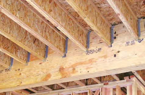
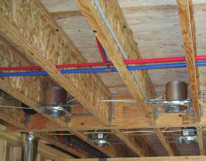
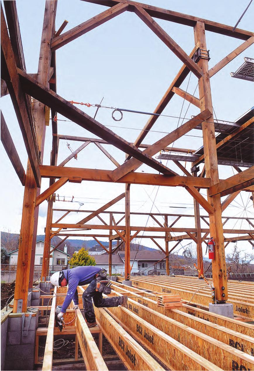
2 2 The SIMPLE FRAMING SYSTEM Makes Designing Homes Easier Architects, engineers, and designers trust Boise Cascade's engineered wood products to provide a better system for framing floors and roofs. It's the SIMPLE FRAMING SYSTEM, featuring beams, joists and rim boards that work together as a system, so you spend less time cutting and fitting. In fact, the SIMPLE FRAMING SYSTEM uses fewer pieces and longer lengths than conventional framing, so you'll complete jobs in less time. You'll Build Better Homes with the SIMPLE FRAMING SYSTEM Now it's easier than ever to design and build better floor systems. When you specify the SIMPLE FRAMING SYSTEM, your clients will have fewer problems with squeaky floors and ceiling gypsum board cracks. The SIMPLE FRAMING SYSTEM also means overall better floor and roof framing than dimension lumber allows. Better Framing Doesn't Have to Cost More Boise Cascade Engineered Wood Products' SIMPLE FRAMING SYSTEM often costs less than conventional framing methods when the resulting reduced labor and materials waste are con sidered. There's less sorting and cost associated with disposing of waste because you order only what you need. Although our longer lengths help your clients get the job done faster, they cost no more. Environmentally Sound As an added bonus, floor and roof systems built with s require about half the number of trees as those built with dimension lumber. This helps you design a home both you and future generations will be proud to own. What Makes the SIMPLE FRAMING SYSTEM So Simple? Floor and Roof Framing with s Light in weight, but heavyduty, s have a better strength / weight ratio than dimension lumber. Knockouts can be removed for crossventila tion and wiring. Ceilings Framed with s The consistent size of s helps keep gypsum board flat and free of unsightly nail pops and ugly shadows, while keeping finish work to a minimum. VERSALAM Beams for Floor and Roof Framing These highlystable beams are free of the largescale defects that plague dimension beams. The result is quieter, flatter floors (no camber) and no shrinkagerelated callbacks. Boise Cascade Rimboard Boise Cascade Engineered Wood Products offer several engineered rimboard products regionally, including BC RIM BOARD OSB, VERSARIM, VERSASTRAND 0. and VERSALAM (check supplier or Boise Cascade EWP rep for availability). These products work with s to provide a solid connection at the critical floor/wall intersection. Table of Contents Product Profiles, Specifications Residential Floor Tables, About Floor Performance, One Hour Floor/Ceiling Assembly Floor Framing Details Hole Location and Sizing... Cantilever Details, Web Stiffener Requirements Floor Tables Roof Framing Details Roof Tables Roof Tables Design Properties, Allowable Nail Spacing.... Boise Cascade Rimboard Products VERSALAM Products, Specifications, Allowable Holes.... VERSALAM Details, Multiple Member Connectors... 2 VERSALAM Floor Tables (100% Duration) VERSALAM Roof Tables (115% Duration) VERSALAM Non Roof Tables (125% Duration).... VERSALAM Closest Allowable Nail Spacing VERSALAM Design Values VERSALAM Columns, VERSASTUD... Computer Software Framing Connectors Lifetime Guarantee... Back Cover On the cover (main photo): Adroit Construction: Ashland, OR: Willow Winds Restoration

3 Western Product Profiles 3 Architectural Specifications Scope: This work includes the complete furnishing and installation of all s as shown on the drawings, herein specified and necessary to complete the work. Materials: s shall be manufactured by Boise Cascade Engineered Wood Products with oriented strand board webs, VERSALAM laminated veneer lumber flanges and water proof, structural adhesives. webs shall be graded Structural I Exposure 1 by an agency listed by a model code evaluation service. Strands on the face layers of the web panels shall be oriented vertically in the joist. The web panels shall be glued together to form a continuous web member. The web panels shall be machined to fit into a groove in the center of the wide face of the flange members so as to form a pressed glue joint at that junction. Design: The s shall be sized and detailed to fit the dimensions and loads indicated on the plans. All designs shall be in accordance with allowable values and section properties developed in accordance with ASTM D5055 and listed in the governing code evaluation service's report. Drawing: Additional drawings showing layout and detail necessary for determining fit and placement in the building are (are not) to be provided by the supplier. Fabrication: The s and section properties shall be manufactured in a plant evaluated for fabrication by the governing code evaluation service and under the supervision of a thirdparty inspection agency listed by the corresponding evaluation service. Storage and Installation: The s, if stored prior to erection, shall be stored in a vertical and level position and pro tected from the weather. They shall be handled with care so they are not damaged. The s are to be installed in accordance with the plans and the Boise Cascade Engineered Wood Products Installation Guide. Temporary construction loads which cause stresses beyond design limits are not permitted. Erection bracing shall be provided to keep the s straight and plumb as required and to assure adequate lateral support for the individual s and the entire system until the sheathing material has been applied. Codes: The s shall be evaluated by a model code evaluation service.
4 4 Residential Floor Tables Homeowner s expectations and opinions vary greatly due to the subjective nature of rating a new floor. Communication with the ultimate end user to determine their expectation is critical. Vibration is usually the cause of most complaints. Installing lateral bridging may help; however, squeaks may occur if not installed properly. Spacing the joists closer together does little to affect the perception of the floor's performance. The most common methods used to increase the performance and reduce vibration of wood floor systems is to About Floor Performance increase the joist depth, limit joist deflections, glue and screw a thicker, tongueandgroove subfloor, install the joists vertically plumb with levelbearing supports, and install a directattached ceiling to the bottom flanges of the joists. The floor span tables listed below offer three very different performance options, based on performance requirements of the homeowner. 9½" Series " " THREE STAR FOUR STAR CAUTION deflection limited to L/40: The common industry and design community standard for residential floor joists, 33% stiffer than L/30 code minimum. However, floor performance may still be an issue in certain applications, especially with 9 1 /2" and 11 /" deep joists without a directattached ceiling. 12" 19.2" " " deflection limited to L/90+: In addition to providing a floor that is 100% stiffer than the three star floor, field experience has been incorporated into the values to provide a floor with a premium performance level for the more discriminating homeowner. 12" 19.2" " " MINIMUM STIFFNESS ALLOWED BY CODE CAUTION deflection limited to L/30: Floors that meet the minimum building code L/30 criteria are structurally sound to carry the specified loads; however, there is a much higher risk of floor performance issues. This table should only be used for applications where floor performance is not a concern. 1' 1'' 15' '' ' 9'' 13' 9'' 12' 0'' 11' '' 11' '' 10' 0'' 10' 0'' 9' '' 1' 11'' 1' 0'' 15' '' 13' 11'' 12' 0'' 1' 11'' 1' 5'' 15' '' ' 5'' 13' 2'' 11' '' 11' '' 10' 0'' 10' 0'' 9' 10'' 19' 10'' 1' 2'' 1' 2'' 15' 9'' 13' '' 1' 5'' 1' 10'' 15' 11'' ' 10'' 13' '' 11' '' 11' '' 10' 0'' 10' 0'' 10' 0'' 20' 5'' 1' '' 1' '' 1' 5'' ' 3'' 20' 2'' 1' 5'' 1' 5'' 15' 9'' 13' 4'' 15' '' ' 4'' 13' '' 12' '' 11' 5'' 22' 3'' 19' 4'' 1' '' 15' 9'' 13' 4'' 21' 3'' 19' 5'' 1' 4'' 1' 1'' ' 10'' 15' '' 15' 1'' ' 3'' 13' 3'' 12' 0'' 23' '' 21' '' 20' 0'' 1' 11'' ' 10'' 21' 11'' 20' 0'' 1' 11'' 1' '' ' 10'' 1' 0'' 15' '' ' 9'' 13' '' 12' 5'' ' 3'' 22' 2'' 20' 11'' 1' 10'' ' 10'' 23' 3'' 21' 3'' 20' 1'' 1' '' 1' 4'' 1' 0'' 1' '' 15' '' ' '' 13' 2'' 25' 9'' 23' '' 22' 3'' 20' 9'' 1' 4'' ' 3'' 23' 11'' 22' '' 20' 11'' 19' 1'' 19' 0'' 1' '' 1' '' 1' 2'' ' '' 29' 0'' ' '' 25' 0'' 23' 3'' 19' 4'' 22' 11'' 21' 0'' 19' 2'' 1' 2'' 13' 11'' 1' 0'' 1' 5'' 15' '' ' 5'' 13' 1'' ' 4'' 21' 0'' 19' 2'' 1' 2'' 13' 11'' ' 2'' 22' 2'' 20' 11'' 19' '' 15' 5'' 1' 11'' 1' 3'' 1' 3'' 15' 2'' 13' 9'' ' 9'' 23' 11'' 21' 10'' 19' '' 15' 5'' ' 10'' 22' 9'' 21' 5'' 20' 0'' 15' 5'' 19' 5'' 1' 9'' 1' '' 15' '' ' 1'' 2' '' 25' 1'' 22' 11'' 20' '' 15' 5'' ' 5'' ' 2'' 22' 9'' 21' 3'' 1' 4'' 20' '' 1' 10'' 1' 9'' 1' 5'' ' 11'' 29' 3'' ' '' 25' 3'' 21' 10'' 1' 4'' 29' 9'' 2' 1'' 25' '' 23' '' 19' '' 23' 3'' 21' 1'' 19' 9'' 1' 4'' 1' '' ' 10'' ' 0'' ' 3'' ' 0'' 19' '' ' 9'' ' 5'' 23' 1'' 20' 10'' 15' 9'' 20' 11'' 19' 1'' 1' 0'' 1' 9'' 15' 2'' 29' '' 25' '' 23' 4'' 20' 10'' 15' 9'' 2' 5'' 25' 1'' 23' '' 21' 1'' 15' 9'' 21' '' 19' '' 1' 5'' 1' 2'' 15' '' ' 4'' ' 11'' ' '' 21' 1'' 15' 9'' 29' 3'' ' '' 25' 2'' 21' 10'' 1' 4'' 22' 10'' 20' 10'' 19' '' 1' 2'' 1' 4'' ' 4'' 29' '' 2' 4'' 21' 10'' 1' 4'' ' 11'' 29' 11'' ' 2'' ' 2'' 19' '' 25' '' 23' 4'' 21' 11'' 20' 3'' 1' 4'' 3' 4'' 33' 2'' 31' 3'' ' 2'' 19' '' 35' 11'' ' '' ' 9'' ' '' 23' 10'' ' 1'' 25' 5'' 23' 11'' 22' 2'' 20' 0'' 39' '' 3' 2'' ' 1'' 31' 9'' 23' 10'' 3' 10'' 35' 4'' 33' 4'' ' 11'' ' '' ' 4'' 2' '' 25' 11'' ' 0'' 21' '' 42' 11'' 39' 1'' 3' 10'' ' 11'' ' '' 12" 19.2" " " Table values based on residential floor loads of 40 psf live load and 10 psf dead load (12 psf dead load for joists). values assume 23 /" min plywood/osb rated sheathing is glued and nailed to joists for composite action (joists spaced at " require sheathing rated for such spacing ⅞" plywood/osb). Table values represent the most restrictive of simple or multiple span applications. Table values are the maximum allowable clear distance between supports. See Boise Cascade Fire Design & Installation Guide US version for specific specific assembly information and other fire resistive options or contact your local Boise Cascade representative. OneHour Fire Resistive Assembly Table values assume minimum bearing lengths without web stiffeners for joist depths of inches and less (1" & 20" joists require web stiffeners at all bearing locations). Floor tile will increase dead load and may require specific deflection limits, contact Boise Cascade EWP Engineering for further information. This table was designed to apply to a broad range of applications. It may be possible to exceed the limitations of this table by analyzing a specific application with the BC CALC sizing software. ICC ESR 133 FIRE ASSEMBLY COMPONENTS 1. Min. 23 /" thick tongue and groove sheathing (exterior glue), installed with long edge perpendicular to joist length, staggered one joist spacing with adjacent sheets, and glued to joists with construction adhesive. 2. s at " or less. 3. Two layers ⅝" Type X or two layers ½" Type C gypsum board, installed per Figures 2 or 3 of ICC ESR 133. SOUND ASSEMBLY COMPONENTS When constructed with resilient channels Add carpet & pad to fire assembly: STC=54 IIC= or Add 3½" glass fiber insulation to fire assembly: STC=55 IIC=4 or Add an additional layer of minimum ⅝" sheathing STC=1 IIC=50 and 9½" glass fiber insulation to fire assembly:

5 Floor Framing 5 For load bearing cantilever details, see page 9. s, VERSALAM and ALLJOIST must be stored, installed and used in accordance with the Boise Cascade EWP Installation Guide, building codes, and to the extent not inconsistent with the Boise Cascade EWP Installation Guide, usual and customary building practices and standards. VERSALAM, ALLJOIST, and s must be wrapped, covered, and stored off of the ground on stickers at all times prior to installation. VERSA LAM, ALLJOIST and s are intended only for applications that assure no exposure to weather or the elements and an environment that is free from moisture from any source, or any pest, organism or substance which degrades or damages wood or glue bonds. Failure to correctly store, use or install VERSALAM, ALLJOIST, and in accordance with the Boise Cascade EWP Installation Guide will void the limited warranty. SAFETY WARNING DO NOT ALLOW WORKERS ON JOISTS UNTIL ALL HANGERS, RIM JOISTS, RIM BOARDS, BLOCKING PANELS, XBRACING AND TEMPORARY 1x4 STRUT LINES ARE INSTALLED AS SPECIFIED BELOW. SERIOUS ACCIDENTS CAN RESULT FROM INSUFFICIENT ATTENTION TO PROPER BRACING DURING CONSTRUCTION. ACCIDENTS CAN BE AVOIDED UNDER NORMAL CONDITIONS BY FOLLOWING THESE GUIDELINES: Build a braced end wall at the end of the bay, or permanently install the first eight feet of s and the first course of sheathing. As an alternate, temporary sheathing may be nailed to the first four feet of s at the end of the bay. All hangers, rim joists, rim boards, blocking panels, and xbracing must be completely installed and properly nailed as each is set. Install temporary 1x4 strut lines at no more than eight feet on center as additional s are set. Nail the strut lines to the sheathed area, or braced end wall, and to each with two d nails. The ends of cantilevers must be temporarily secured by strut lines on both the top and bottom flanges. Straighten the s to within 1 /2 inch of true alignment before attaching strut lines and sheathing. Remove the temporary strut lines only as required to install the permanent sheathing. Failure to install temporary bracing may result in sideways buckling or rollover under light construction loads. Do not stack construction materials (sheathing, drywall, etc) in the middle of BCI spans, contact Boise Cascade EWP Engineering for proper storage and shoring information.
6 Floor Framing Details Additional floor framing details available with BC FRAMER software (see page 33) F0 END BEARING DETAILS F0A F02 F01 F2A F0 F10 F52 F0 F03 LATERAL SUPPORT s shall be laterally supported at the ends with hangers, rimboard, rim joist or blocking panels. blocking panels or rimboard are required at cantilever supports. Blocking may be required at intermediate bearings for floor diaphragm per IRC in high seismic areas, consult local building official. MINIMUM BEARING LENGTH FOR JOISTS Minimum Bearing Lengths: 1½" end bearing, 3½" intermediate and adjacent cantilever bearing. Longer bearing lengths allow higher reaction values. Refer to the building code evaluation report or the BC CALC software. NAILING REQUIREMENTS rim joist, rim board or closure panel to joist: Rims or closure panel 1¾ inches thick and less: d nails, one each in the top and bottom flange rim joist: 210d box nails, one each in the top and bottom flange. 000, 0 rim joist: 21d box nails, one each in the top and bottom flange. 500, 90 rim joist: Toenail top flange to rim joist with 210d box nails, one each side of flange. rim joist, rim board or blocking panel to support: Min. d " per IRC. Connection per design professional of record's specification for shear transfer. INTERMEDIATE BEARING DETAILS F09 F5 F F05 joist to support: d nails, one on each side of the web, placed 1½ inches minimum from the end of the to limit splitting. Sheathing to joist: Prescriptive residential floor sheathing nailing requires d common " on edges 12" in the field (IRC Table R02.3(1)). See closest allowable nail spacing limits on page for floor diaphragm nailing specified at closer spacing than IRC. Maximum nail spacing for minimum lateral stability: 1" for 5000, " for larger joist series. gauge staples may be substituted for d nails if the staples penetrate at least 1 inch into the joist. Wood screws may be acceptable, contact local building official and/or Boise Cascade EWP Engineering for further information. BACKER AND FILLER BLOCK DIMENSIONS Series Backer Block Thickness Filler Block Thickness ¾" or ⅞" wood panels Two ¾" wood panels or 2x_ ⅛" or two ½" wood panels 2x_ + 1 " or ½" wood panel ⅛" or two ⅝" wood panels 2x_ + ⅝" or ¾" wood panel ⅛" or two ½" wood panels 2x_ + 1 " or ½" wood panel x_ lumber Double 2x_ lumber Cut backer and filler blocks to a maximum depth equal to the web depth minus ¼" to avoid a forced fit. F Minimum Heel End Roof Pitch Wall Bearing /12 /12 /12 9/12 10/12 12/12 2 x " 4 5 4¼" 4¼" 4¼" 4¼" 2 x 3 3 " ¾" 2 9 2¼" RIM JOISTS AND BLOCKING Vertical Capacity [in] Series No W.S. (1) W.S. (2) 9½" , , N/A , , , N/A N/A , , 0 2.0, N/A N/A , , " 0 2.0, N/A " N/A 200 (1) No web stiffeners required (2) Web stiffeners required at each end of blocking, values not applicable for rim joists N/A: Not applicable WEB STIFFENER REQUIREMENTS See Web Stiffener Requirements on page 9. PROTECT JOISTS FROM THE WEATHER s are intended only for applications that provide permanent protection from the weather. Bundles of s should be covered and stored off of the ground on stickers.
7 Hole Location & Sizing s are manufactured with 1 1 /2" round perforated knockouts in the web at approximately 12" on center D (see table below) Minimum spacing = 2x greatest dimension of largest hole (knockouts exempt) D (see table below) DO NOT cut or notch flange " " Minimum distance from support, listed in table below, is required for all holes greater than 1½" MINIMUM DISTANCE (D) FROM ANY SUPPORT TO THE CENTERLINE OF THE HOLE Round Hole Diameter [in] Rectangular Hole Side [in] Any 9½" " [ft] No holes (except knockouts) allowed in bearing zones A 1 1 /2" round hole may be cut anywhere in the web. Provide at least 3" of clearance from other holes. " " Do not cut holes larger than 1 1 /2" round in cantilevers ⅞ '0'' 1'1'' 1''' 2'4'' 2'11'' 3''' 12 1 Round Hole Diameter [in] Rectangular Hole Side [in] 1'0'' 1'0'' 2 1''' 2'2'' 3 2''' 3'5'' 4 3''' 4''' 5 2 4'5'' 5'11'' 3 5'4'' '2'' 5 / '0'' 1'1'' 1''' 2'0'' 2'5'' 2'11'' 3'5'' 3'10'' Any 12 1'0'' 1''' 2'3'' 3'0'' 3''' 4'5'' 5'1'' 5'9'' [ft] 1 1'2'' 2'1'' 3'0'' 4'0'' 4'11'' 5'10'' '10'' ''' 20 Round Hole Diameter [in] Rectangular Hole Side [in] 1'5'' 2 2''' 3 3'10'' 4 5'0'' 5 '2'' 2 '4'' 3 ''' 5 9''' / '0'' 1'1'' 1'2'' 1'2'' 1''' 1'11'' 2'4'' 2'9'' 3'3'' 3''' 12 1'0'' 1'1'' 1'2'' 1''' 2'3'' 2'11'' 3''' 4'1'' 4'10'' 5''' Any [ft] 1 1'0'' 1'1'' 1'3'' 2'2'' 3'0'' 3'10'' 4'9'' 5''' ''' '4'' 20 1'0'' 1'1'' 1''' 2''' 3'9'' 4'10'' 5'11'' '10'' '1'' 9'2'' Round Hole Diameter [in] Rectangular Hole Side [in] 1'0'' 2 1'1'' 3 1'11'' 4 3'3'' 5 4''' 5'10'' 2 '1'' 3 '3'' / 5 9'9'' 10 11'0'' '0'' 1'1'' 1'2'' 1'2'' 1'3'' 1'3'' 1''' 1'11'' 2'4'' 2'9'' 3'2'' 3''' 12 1'0'' 1'1'' 1'2'' 1'2'' 1'3'' 1'9'' 2'4'' 2'11'' 3''' 4'2'' 4'9'' 5'4'' Any [ft] 1 1'0'' 1'1'' 1'2'' 1'2'' 1''' 2'5'' 3'2'' 3'10'' 4'9'' 5''' '4'' '2'' 20 1'0'' 1'1'' 1'2'' 1'2'' 2'0'' 3'0'' 4'0'' 4'10'' 5'11'' '11'' '11'' '11'' Round Hole Diameter [in] Rectangular Hole Side [in] 1'0'' 2 1'1'' 3 1'2'' 4 1'3'' 5 2'5'' 3''' 4'9'' 2 5'10'' / 3 '2'' 10 5 '4'' 11 9''' 12 10'9'' '0'' 1'1'' 1'2'' 1'2'' 1'5'' 1'11'' 2'4'' 2'9'' 3'3'' 3'9'' 4'2'' 4''' 5'1'' 5''' 1" [ft] '0'' 1'0'' 1'0'' 1'1'' 1'1'' 1'1'' 1'2'' 1'2'' 1'2'' 1'4'' 1''' 2'0'' 1'11'' 2'5'' 2'11'' 2''' 3'3'' 3'10'' 3'2'' 4'0'' 4'9'' 3''' 4''' 5''' 4'5'' 5''' ''' 5'0'' '3'' ''' 5''' '0'' '5'' '3'' '9'' 9'4'' '10'' ''' 10'3'' '5'' 9'4'' 11'2'' 1'0'' 1'1'' 1'4'' 2'5'' 3'5'' 4''' 5''' ''' '9'' '9'' 9'10'' 10'11'' 12'0'' 13'1'' Round Hole Diameter [in] Rectangular Hole Side [in] / '0'' 1'1'' 1'2'' 1'2'' 1'3'' 1''' 1'11'' 2'3'' 2'9'' 3'2'' 3''' 3'11'' 4'4'' 4'9'' 20" [ft] '0'' 1'0'' 1'0'' 1'0'' 1'1'' 1'1'' 1'1'' 1'1'' 1'2'' 1'2'' 1'2'' 1'2'' 1'2'' 1'3'' 1''' 1'9'' 1''' 1'11'' 2'4'' 2''' 2'1'' 2''' 3'1'' 3''' 2''' 3'3'' 3'11'' 4''' 3'1'' 3'10'' 4''' 5'5'' 3''' 4''' 5''' ''' 4'3'' 5'3'' '4'' '5'' 4'9'' 5'11'' '2'' '4'' 5'3'' ''' '11'' 9'3'' 5'10'' '4'' '9'' 10'3'' '4'' '0'' 9''' 11'2'' DO cut in web area as specified Select a table row based on joist depth and the actual joist span rounded up to the nearest table span. Scan across the row to the column headed by the appropriate round hole diameter or rectangular hole side. Use the longest side of a rectangular hole. The table value is the closest that the centerline of the hole may be to the centerline of the nearest support. The entire web may be cut out. DO NOT cut the flanges. Holes apply to either single or multiple joists in repetitive member conditions. For multiple holes, the amount of uncut web between holes must equal at least twice the diameter (or longest side) of the largest hole. 1 / 2 " round knockouts in the web may be removed by using a short piece of metal pipe and hammer. Holes may be positioned vertically anywhere in the web. The joist may be set with the 1 1 / 2 " knockout holes turned either up or down. This table was designed to apply to the design conditions covered by tables elsewhere in this publication. Use the BC CALC software to check other hole sizes or holes under other design conditions. It may be possible to exceed the limitations of this table by analyzing a specific applica tion with the BC CALC software.
8 Reinforced Bearing Cantilever Table [in] 9½" KEY TO TABLE 1 Web Stiffeners Plus One Reinforcer 0 No Reinforcement Required 2 Web Stiffeners Plus Two Reinforcers s WS Web Stiffeners at Support X Use Deeper s or Closer Spacing Series Roof Truss [ft] Cut 4" long reinforcers to match the joist depth. Use min. 23 / " plywood/osbrated sheathing, Exposure 1, 4/ Rating panels. The face grain must be horizontal (measure the 4" dimension along the long edge of the panel). 2. Fasten the reinforcer to the joist flanges with d nails at " When reinforcing both sides, stagger the nails to avoid splitting the joist flanges. Roof Total [psf] Spacing [in] X 0 X X X 0 X X 0 0 X 0 0 X 0 X X 0 0 X 0 X X X X X 0 0 X 0 X X X X X 0 0 X 0 X X X X X 0 0 X 0 X X X X X 0 X X X X X X X X 0 X X X X X X X X X X X X 0 1 X X 0 X X X 0 X X 0 0 WS 0 0 X 0 X X X 0 X X 0 0 X 0 X X 1 X X WS 0 0 X X X X 0 1 X X 0 1 X 0 0 WS 0 0 X 0 1 X X 0 X X X 1 X X WS 0 0 X WS 0 0 X WS 0 WS X X 0 WS X 0 0 WS 0 0 X 0 X X 0 0 WS 0 0 X 0 X X 0 0 WS 0 WS X 0 X X WS X WS X X 0 0 X 0 X X X X X WS 0 0 X X WS X X 0 0 WS 0 0 X 0 1 X 0 0 WS 0 0 X 0 1 X WS X 0 1 X WS 0 0 X X WS X X 0 0 WS 0 0 X 0 1 X 0 0 WS 0 0 X 0 1 X WS X 0 X X X X X X 0 1 X X 0 1 X X 0 1 X X 0 X X Attach web stiffeners per intermediate Web Stiffener Nailing Schedule on page Use the BC CALC software to analyze conditions that are not covered by this table. It may be possible to exceed the limitations of this table by analyzing a specific application with BC CALC software. [in] Series Roof Truss [ft] Roof Total [psf] Spacing [in] WS 0 0 WS WS WS 0 WS X WS 0 WS X 0 0 WS WS X 0 0 WS WS X 0 0 WS 0 WS X 0 1 X 0 0 WS 0 WS X WS X X WS 0 0 WS WS WS WS 0 WS X WS 0 WS X 0 0 WS WS X 0 0 WS X WS 0 0 WS WS WS 0 0 X WS 0 WS X 0 0 WS 0 0 WS 0 WS X 0 0 WS WS X 0 0 WS 0 0 X 0 1 X WS WS WS WS 0 WS WS X 0 0 WS X WS 0 0 WS WS 0 0 WS WS 0 WS WS WS 0 WS X 0 0 WS 0 0 WS 0 WS X 0 0 WS 0 0 WS 0 WS X WS 0 0 WS WS 0 0 WS WS 0 0 WS WS 0 WS WS WS 0 WS X 0 0 WS 0 0 WS 0 WS X 0 0 WS 0 0 WS 0 WS X WS 0 0 WS WS 0 0 WS WS 0 WS WS WS 0 WS WS 0 WS WS 0 0 WS 0 WS
9 Reinforced Bearing Cantilever Detail 9 Roof The tables and details on pages and 9 indicate the type of reinforcements, if any, that are required for loadbearing cantilevers up to a maximum length of 2' 0". Cantilevers longer than 2'0" cannot be reinforced. However, longer cantilevers with lower loads may be allowable without reinforcement. Analyze specific applica tions with the BC CALC software. blocking 2'" 2'0" s are intended only for applications that provide permanent protection from the weather. F15A PLYWOOD / OSB REINFORCEMENT (If Required per BC CALC analysis) Analyze Bearing Cantilevers in BC CALC Software 23 /" Min. x 4" long plywood / OSB rated sheathing must match the full depth of the. Nail to the with d nails at " and nail with 4d nails into backer block. When reinforcing both sides, stagger nails to limit splitting. Install with horizontal face grain. Contact Boise Cascade EWP Engineering for reinforcement requirements on depths greater than. Wood Structural Panel Closure 23 /" min. plywood/osb or rimboard closure. Nail with d nail into each flange. Structural Panel reinforcement Non Bearing Wall Cantilever Details Wood backer block See page of Western Specifier Guide 2'0" 2'0" 2x minimum blocking required for cantilever Backer block Uplift on backspan shall be considered in all cantilever designs Fasten the 2x minimum to the by nailing through the backer block and joist web with 2 rows of 10d nails at " on center. Use 1d nails with joists. Clinch all nails. F15B F05 2x Closure blocking Back Drywall Ceiling or Wood Structural Maximum Panel Soffit 1 /3 Back Not to exceed 4'0" These details apply to cantilevers with uniform loads only. It may be possible to exceed the limitations of these details by analyzing a specific application with the BC CALC software. Series F1E Web Stiffener Specifications For Structural Lateral Capacity Restraint in (Min. Thick) Hanger 3 1 /2" min. bearing Back Web Stiffener Requirements Minimum Width ⅝" ¾" 2 5 / 1 " ¾" ⅞" 2 5 / 1 " ¾" 1" or 1⅛" 2 5 / 1 " ¾" ⅞" 2 5 / 1 " x4 lumber (vertical) NOTES Web stiffeners are optional except as noted below. Web stiffeners are always required for all 1" and 20" s at all bearing locations. Web stiffeners are always required in hangers that do not extend up to support the top flange of the. Web stiffeners may be required with certain sloped or skewed hangers or to achieve uplift values. Refer to the hanger manufacturer's installation requirements. Web stiffeners are always required in certain roof applications. See Roof Framing Details on page. Web stiffeners are always required under concentrated loads that exceed 1000 pounds. Install the web stiffeners snug to the top flange in this situation. Follow the nailing schedule for intermediate bearings. Web stiffeners may be cut from structural rated wood panels, engineered rimboard or 2x lumber ( 90 only). For Structural Capacity: Web stiffeners needed to increase the s reaction capacity at a specific bearing location. Lateral Restraint in Hanger: Web stiffeners needed when hanger does not lateral support the top flange (e.g., adjustable height hangers). Web stiffeners may be of multiple thickness (e.g., 500, double ½" panel OK). Web stiffeners may be used to increase allowable reaction values. See Design Properties on page or the BC CALC software. Minimum 1 1 /2 Times Cantilever Length Maximum 1 /3 Back not to exceed 4'0" Section View Web Stiffener Nailing Schedule Bearing Location Series End Intermediate 9½" d d 5000 d 3d 1. d 5d ½" d d d 3d d 5d d d 9½" d d d 3d d 5d d d d 3d d 5d d d 31d 31d 51d 51d 1d 1d 1" 1d 1d 20" 1d 1d
10 10 Floor Tables Allowable Uniform Floor (in pounds per linear foot [PLF]) 100% Duration Length ½" Series 2" Flange Width Total Total Total 9½" Total Series 2 5 / Flange Width Total Total Total Total values are limited by shear, moment, or deflection equal to L/0. values are limited by deflection equal to L/40. For deflection limits of L/30 and L/90, multiply the values by 1.33 and 0.50 respectively. Both the Total and columns must be checked. Where a value is not shown, the Total value will control. Table values apply to either simple or multiple span joists. is measured center to center of the minimum required bearing length. Analyze multiple span joists with the BC CALC software if the length of any span is less than half the length of an adjacent span. Table values do not consider composite action from gluing and nailing floor sheathing (composite action is considered in floor span tables on page 4). Total values assume minimum bearing lengths without web stiffeners for joist depths of 1 inches and less. 1 and 20 inch joists require web stiffeners. For assistance with floor design, consult the section About Floor Performance on page 4. This table was designed to apply to a broad range of applications. It may be possible to exceed the limitations of this table by analyzing a specific application with the BC CALC software.
![Floor Tables 11 Allowable Uniform Floor (in pounds per linear foot [PLF]) Length 9 10 11 12 13 15 1 1 1 19 20 21 22 23 25 2 29 9½" 500 1. Total 500 1. Series 2 9 / Flange Width 500 1.](/docs-images/72/67804444/images/11-1.jpg "100% Duration 500 1. 500 1. Total 0 2.0 0 2.")
11 Floor Tables 11 Allowable Uniform Floor (in pounds per linear foot [PLF]) Length ½" Total Series 2 9 / Flange Width % Duration Total Series 2 5 / Flange Width Total Total Total Total Total
12 12 Floor Tables Allowable Uniform Floor (in pounds per linear foot [PLF]) 100% Duration Series 3½" Flange Width " " Length Total Total Total Total Total Total values are limited by shear, moment, or deflection equal to L/0. values are limited by deflection equal to L/40. For deflection limits of L/30 and L/90, multiply the values by 1.33 and 0.50 respectively. Both the Total and columns must be checked. Where a value is not shown, the Total value will control. Table values apply to either simple or multiple span joists. is measured center to center of the minimum required bearing length. Analyze multiple span joists with the BC CALC software if the length of any span is less than half the length of an adjacent span. Table values do not consider composite action from gluing and nailing floor sheathing (composite action is considered in floor span tables on page 4). Total values assume minimum bearing lengths without web stiffeners for joist depths of 1 inches and less. 1 and 20 inch joists require web stiffeners. For assistance with floor design, consult the section About Floor Performance on page 4. This table was designed to apply to a broad range of applications. It may be possible to exceed the limitations of this table by analyzing a specific application with the BC CALC software.
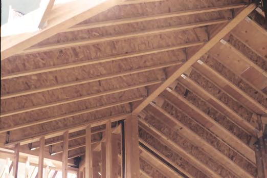
13 Roof Framing 13 Rafters FOR INSTALLATION STABILITY, Temporary strut lines (1x4 min.) ft. on center maximum. Fasten at each joist with two d nails minimum. Structural ridge VERSALAM or loadbearing wall required. Blocking or other lateral support required at end supports. Blocking not shown for clarity. Rafter Header When installing Boise Cascade EWP products with treated wood, use only connectors/ fasteners that are approved for use with the corresponding wood treatment. Multiple Rafters may be required. SAFETY WARNING DO NOT ALLOW WORKERS ON JOISTS UNTIL ALL HANGERS, RIM JOISTS, RIM BOARDS, BLOCKING PANELS, XBRACING AND TEMPORARY 1x4 STRUT LINES ARE INSTALLED AS SPECIFIED BELOW. Build a braced end wall at the end of the bay, or permanently install the first eight feet of s and the first course of sheathing. As an alternate, temporary sheathing may be nailed to the first four feet of s at the end of the bay. All hangers, rim joists, rim boards, blocking panels, and xbracing must be completely installed and properly nailed as each is set. Install temporary 1x4 strut lines at no more than eight feet on center as additional s are set. Nail the strut lines to the sheathed area, or braced end wall, and to each with two d nails. SERIOUS ACCIDENTS CAN RESULT FROM INSUFFICIENT ATTENTION TO PROPER BRACING DURING CONSTRUCTION. ACCIDENTS CAN BE AVOIDED UNDER NORMAL CONDITIONS BY FOLLOWING THESE GUIDELINES: The ends of cantilevers must be temporarily secured by strut lines on both the top and bottom flanges. Straighten the s to within 1 /2 inch of true alignment before attaching strut lines and sheathing. Remove the temporary strut lines only as required to install the permanent sheathing. Failure to install temporary bracing may result in sideways buckling or rollover under light construction loads. Ceiling with Bevel End Cut (For LimitedAccess Attics Only) shall not be used as collar/tension tie. BCI 5000, 000, 500 Maximum Lengths Without Roof s 9½" / / '" / / '0" / '0" (If roof loads present, see Notes 2 & 3 at right) Minimum Heel s End Wall 2 x 4 2 x 9½" 2½" 1½" 3½" 2½" 4½" 3½" Notes: 1) Detail is to be used only for ceiling joists with no access to attic space. 2) Ceiling joist must be designed to carry all roof load transferred through rafter struts as shown. 3) ceiling joist end reaction may not exceed 550 pounds. 4) Minimum roof slope is /12. 5) Nail roof rafter to top flange with 11d sinker or box nail. ) Nail top flange to roof rafter with 11d nail (for stability resistance only). ) Install a web stiffener on each side of at beveled ends. Nail roof rafter to per building code requirements for ceiling joist to roof rafter connection.
14 Roof Framing Details Additional roof framing details available with BC FRAMER software (see page 33) R01 R04 R02 DN05 R03 R0 Western Specifier Guide. R05 R0 R11 LATERAL SUPPORT s must be laterally supported at end supports (including supports adjacent to overhangs) with hangers, rimboard, or blocking (VERSALAM, Boise Cascade Rimboard or ). Metal cross bracing or other xbracing provides adequate lateral support for s, consult governing building code for roof diaphragm connection provisions. MINIMUM BEARING LENGTH FOR JOISTS Minimum Bearing Lengths: 1½" end bearing, 3½" intermediate and adjacent cantilever bearing. Longer bearing lengths allow higher reaction values. Refer to the building code evaluation report or the BC CALC software. NAILING REQUIREMENTS rim joist, rim board or closure panel to joist: Rims or closure panel 1¾ inches thick and less: d nails, one each in the top and bottom flange rim joist: 210d box nails, one each in the top and bottom flange. 000, 0 rim joist: 21d box nails, one each in the top and bottom flange. 500, 90 rim joist: Toenail top flange to rim joist with 210d box nails, one each side of flange. rim joist, rim board or blocking panel to support: Min. d " per IRC. Connection per design professional of record's specification for shear transfer. joist to support: d nails, one on each side of the web, placed 1½ inches minimum from the end of the to limit splitting. Sheathing to joist: Prescriptive residential roof sheathing nailing requires d common " on edges 12" in the field (IRC Table R02.3(1)). See closest allowable nail spacing limits on page for floor diaphragm nailing specified at closer spacing than IRC. Maximum nail spacing for minimum lateral stability: 1" for 5000, " for larger joist series. gauge staples may be substituted for d nails if the staples penetrate at least 1 inch into the joist. Wood screws may be acceptable, contact local building official and/or Boise Cascade EWP Engineering for further information. BACKER AND FILLER BLOCK DIMENSIONS Backer Block Series Thickness Filler Block Thickness ¾" or ⅞" wood panels Two ¾" wood panels or 2x_ ⅛" or two ½" wood panels 2x_ + 1 " or ½" wood panel ⅛" or two ⅝" wood panels 2x_ + ⅝" or ¾" wood panel ⅛" or two ½" wood panels 2x_ + 1 " or ½" wood panel x_ lumber Double 2x_ lumber Cut backer and filler blocks to a maximum depth equal to the web depth minus ¼" to avoid a forced fit. WEB STIFFENER REQUIREMENTS See Web Stiffener Requirements on page 9. PROTECT JOISTS FROM THE WEATHER s are intended only for applications that provide permanent protection from the weather. Bundles of s should be covered and stored off of the ground on stickers. MAXIMUM SLOPE Unless otherwise noted, all roof details are valid for slopes of 12 in 12 or less. VENTILATION The 1½ inch, prestamped knockout holes spaced at 12 inches on center along the may all be knocked out and used for cross ventilation. Deeper joists than what is structurally needed may be advantageous in ventilation design. Consult local building official and/or ventilation specialist for specific ventilation requirements. BIRDSMOUTH CUTS s may be birdsmouth cut only at the low end support. joists with birdsmouth cuts may cantilever up to 2'" past the low end support. The bottom flange must sit fully on the support and may not overhang the inside face of the support. High end supports and intermediate supports may not be birdsmouth cut.
15 Roof Tables 15 Maximum clear span in feet and inches, based on horizontal spans. 12" 19.2" " Non 125% 115% Non 125% 115% Non 125% 115% Non 125% 115% [psf] Dead [psf] /12 or Less 115% and 125% Duration Series 2" Flange Width 9½" /12 /12 4/12 4/12 /12 4/12 4/12 to to or to to or to /12 12/12 Less /12 12/12 Less /12 /12 to 12/12 4/12 or Less 9½" /12 to /12 /12 to 12/ Series 2 5 / Flange Width /12 /12 4/12 4/12 to to or to /12 12/12 Less /12 4/12 or Less /12 to 12/12 4/12 or Less /12 to /12 '1" 22'9" 21'1" '" '11" 25'0" '" '" '" 25'" '1" 22'4" '5" '" '" '" '" '4" 3'4" 3'2" 33'" 22'10" 21'5" 19'9" 2'1" 25'5" 23'5" '10" 29'0" '9" '2" 22'" 20'11" '10" 2'1" 25'0" '10" '10" '5" 3'4" '1" 31'5" 21'9" 20'5" 1'9" 25'10" '2" 22'3" 29'5" 2'" 25'4" 23'1" 21'" 19'10" 2'" 25'9" 23'" 31'4" 29'4" '11" '" '5" 29'10" 22'11" 21'" 20'2" 2'2" 25'" 23'10" '10" 29'3" 2'2" '3" 22'11" 21'4" '11" 2'4" 25'5" '11" 31'1" '11" 3'5" '5" '0" 21'10" 20'" 19'0" 25'10" '4" 22'" '9" 2'9" 25'" 23'1" 21'9" 20'2" 2'" 25'11" '0" 31'5" 29'" 2'4" '9" '" '3" 21'11" 20'9" 19'4" 25'11" '" 22'11" '10" '0" '1" 23'2" 21'11" 20'" 2'" '2" '5" 31'" 29'9" 2'9" '10" '11" '9" 21'0" 19'10" 1'4" '10" 23'5" 21'9" 2'2" '" '10" 22'3" 21'0" 19'5" '" 25'0" 23'2" '2" '5" '5" 33'0" 31'" 29'3" 19'11" 19'1" 1'0" 23'" 22'" 21'4" 25'10" 25'5" '4" 21'1" 20'3" 19'1" 25'1" '1" 22'9" '" 2'5" 25'11" 31'4" '5" '" 19'" 1'" 1'3" 22'" 22'0" 20'" '" '1" 23'4" 20'9" 19'" 1'4" '9" 23'5" 21'10" 2'11" '" '10" 29'10" 29'3" 2'" 1'5" 1'" 1'9" 21'" 20'11" 19'11" 23'" 23'3" 22'" 19'" 1'9" 1'9" 23'3" 22'4" 21'2" '" 25'5" '2" '" '2" '" 1'3" 1'" 1'5" 20'9" 20'5" 19'5" 22'" 22'3" 21'" 19'" 1'" 1'4" 23'3" 22'2" 20'" 25'" 25'3" 23'" 2'5" 2'0" '1" 21'10" 20'" 19'1" 25'11" '5" 22'" 29'" 2'10" 25'10" 23'2" 21'10" 20'3" 2'" '0" '2" 31'5" 29'" 2'" '9" '9" '5" 20'" 19'5" 1'11" '" 23'0" 21'3" 2'" '3" '3" 21'11" 20'" 19'0" '1" '" 22'" 29'9" 2'11" 25'9" '11" '11" '" 19'9" 1'" 1'0" 23'5" 21'11" 20'2" 25'10" 25'0" 22'11" 20'11" 19'" 1'0" '11" 23'4" 21'5" '5" '" '5" 31'5" 29'5" 2'0" 20'9" 19'" 1'3" '" 23'3" 21'" '" '1" '" 22'0" 20'9" 19'4" '2" '9" 23'0" 29'10" '2" '3" '5" 31'2" 29'0" 19'9" 1'" 1'3" 22'10" 22'1" 20'5" '10" '3" 23'4" 20'11" 19'9" 1'3" '11" 23'" 21'9" '3" '9" '10" '3" 29'5" 2'5" 19'10" 1'9" 1'" 22'11" 22'3" 20'9" '11" '" 23'" 21'0" 19'11" 1'" 25'0" 23'" 22'1" '4" 2'0" 25'2" '4" 29'9" 2'10" 19'0" 1'11" 1'" 21'" 21'0" 19'9" 23'5" 22'11" 22'2" 20'1" 19'0" 1'" '0" 22'" 21'0" '" 25'9" 23'11" '" 2'10" '" 1'0" 1'4" 1'4" 20'" 20'2" 19'4" 22'4" 22'0" 21'" 19'1" 1'4" 1'3" 22'9" 21'10" 20'" 25'5" '11" 23'" 2'2" '9" '0" 1'2" 1'10" 15'" 19'" 19'1" 1'" 21'3" 20'10" 20'3" 1'9" 1'9" 1'" 22'2" 21'2" 19'9" '2" 23'" 22'" 25'10" 25'4" '" 1'" 1'0" 15'2" 1'" 1'" 1'0" 20'4" 20'1" 19'9" 1'" 1'11" 1'1" 21'1" 20'2" 19'2" 23'2" 22'11" 21'10" '9" '" '1" 15'10" 15'" '10" 1'11" 1'" 1'3" 19'" 19'2" 1'9" 1'" 1'10" 15'9" 20'4" 20'0" 1'9" 22'2" 21'10" 21'4" 23'9" 23'4" 22'10" 20'" 19'4" 1'0" '4" 22'11" 21'4" 2'5" '2" '3" 21'9" 20'" 19'0" 25'11" '5" 22'" 29'" 2'10" 25'10" '" '10" '" 19'5" 1'3" 1'10" 23'0" 21'" 20'0" 25'3" '" 22'9" 20'" 19'4" 1'10" '" 23'0" 21'3" 2'11" '3" '3" '" 29'0" '10" 1'" 1'4" 15'11" 21'" 20'" 1'11" 23'" 22'9" 21'" 19'" 1'4" 1'11" 23'4" 21'11" 20'2" '" '11" 22'11" '" 2'" 25'5" 19'" 1'5" 1'2" 22'4" 21'10" 20'4" '4" 23'10" 23'2" 20'" 19'" 1'2" '" 23'3" 21'" 2'" '" '" 29'" '11" 2'3" 1'4" 1'" 1'2" 20'10" 20'3" 19'2" 22'" 22'1" 21'4" 19'" 1'" 1'2" 23'5" 22'1" 20'5" 25'9" 25'1" 23'4" 2'" '10" 25'9" 1'5" 1'" 1'5" 20'11" 20'" 19'" 22'9" 22'4" 21'10" 19'" 1'" 1'5" 23'" 22'3" 20'9" 25'10" 25'4" 23'" 2'" 2'2" '2" 1'4" 1'10" 15'" 19'" 19'2" 1'" 21'5" 20'11" 20'3" 1'11" 1'10" 1'" 22'4" 21'3" 19'9" '4" 23'9" 22'" '0" 25'5" '" 1'" 1'3" 15'4" 1'" 1'5" 1'0" 20'4" 20'1" 19'" 1'11" 1'2" 1'3" 21'3" 20'" 19'4" 23'2" 22'10" 22'1" '9" '5" 23'11" 15'" 15'4" '" 1'9" 1'5" 1'11" 19'4" 19'0" 1'" 1'" 1'" 15'" 20'2" 19'10" 1'" 22'0" 21'" 21'0" 23'" 23'1" 22'" 15'0" '10" '3" 1'0" 1'10" 1'" 1'" 1'4" 1'0" 1'" 15'11" 15'1" 19'5" 19'0" 1'0" 21'1" 20'10" 20'" 22'" 22'4" 21'11" '5" '2" 13'10" 1'4" 1'1" 15'" 1'10" 1'" 1'1" 1'4" 15'9" '9" 1'" 1'3" 1'" 20'3" 19'11" 19'5" 21'" 21'3" 20'10" 19'0" 1'11" 1'" 22'5" 21'3" 19'9" '" 23'11" 22'" 20'1" 19'0" 1'" '0" 22'" 21'0" 2'4" 25'9" 23'11" 29'9" '" '" 1'0" 1'11" 15'" 20'9" 20'0" 1'" 22'" 21'11" 21'0" 19'0" 1'11" 1'" 22'" 21'4" 19'" 25'" '4" 22'5" 2'5" '" '10" 1'1" 1'1" '9" 19'4" 1'" 1'" 21'1" 20'4" 19'5" 1'2" 1'0" 15'" 21'" 20'3" 1'" 23'11" 23'1" 21'3" 25'" '9" 23'" 1'" 1'1" 15'11" 19'11" 19'" 1'10" 21'9" 21'3" 20'" 19'1" 1'1" 1'10" 22'" 21'" 20'0" '" '2" 22'10" '5" 25'10" 25'2" 1'5" 15'11" 15'0" 1'" 1'1" 1'5" 20'3" 19'9" 19'0" 1'2" 1'2" 15'10" 21'2" 20'5" 1'11" 23'0" 22'5" 21'" '" '0" 23'2" 1'5" 1'2" 15'3" 1'" 1'4" 1'10" 20'4" 20'0" 19'" 1'3" 1'3" 1'2" 21'2" 20'" 19'3" 23'1" 22'" 21'11" '9" '3" 23'" 15'5" 15'1" '" 1'" 1'1" 1'" 19'1" 1'" 1'1" 1'" 1'" 15'4" 19'11" 19'" 1'3" 21'9" 21'3" 20'" 23'3" 22'" 21'11" '" '" '2" 1'" 1'5" 1'1" 1'2" 1'11" 1'" 1'" 15'11" 15'0" 19'0" 1'" 1'11" 20'" 20'4" 20'0" 22'1" 21'9" 21'4" '0" 13'" 13'4" 15'10" 15'" 15'2" 1'3" 1'11" 1'" 15'11" 15'5" '5" 1'0" 1'" 1'2" 19'" 19'3" 1'9" 21'0" 20'" 19'" 13'5" 13'3" 13'0" 15'3" 15'0" '9" 1'" 1'5" 1'1" 15'3" '" '0" 1'4" 1'1" 1'" 1'10" 1'" 1'4" 19'10" 19'5" 1'9" 12'10" 12'" 12'4" '" '4" '0" 15'11" 15'" '11" '" '4" 13'" 1'" 1'4" 15'11" 1'11" 1'4" 1'" 1'3" 1'" 1'10" Table values are limited by shear, moment, total load deflection equal to L/10 and live load deflection equal to L/0. Check the local building code for other deflection limits that may apply. This table was designed to apply to a broad range of applications. It may be possible to exceed the limitations of this table by analyzing a specific application with the BC CALC software. /12 to 12/12 Table values represent the most restrictive of simple or multiple span applications. Table values assume minimum bearing lengths without web stiffeners for joist depths of 1 inches and less. 1 and 20 inch joists require web stiffeners. Slope roof joists at least 1 4" over 12" to minimize ponding. Allowable spans and loads shall be adjusted and checked for wind load as required by local building code.

16 1 Roof Tables Maximum clear span in feet and inches, based on horizontal spans. 115% and 125% Duration Series 2 9 / Flange Width 12" 19.2" " Non 125% 115% Non 125% 115% Non 125% 115% Non 125% 115% [psf] Dead [psf] /12 or Less 9½" /12 /12 4/12 4/12 /12 4/12 4/12 /12 4/12 4/12 to to or to to or to to or to /12 12/12 Less /12 12/12 Less /12 12/12 Less /12 '5'' '11'' 23'1'' 31'5'' 29''' 2'5'' 35'9'' 33''' 31'3'' 39''' 3'3'' ''' 25'0'' 23''' 21''' 29'9'' 2'11'' 25'9'' 33'10'' 31'9'' 29'4'' 3'5'' 35'2'' '5'' 23'10'' 22'4'' 20''' '4'' ''' '5'' '3'' '3'' 2'9'' 35''' 33'5'' '9'' 25'1'' 23''' 22'1'' 29'10'' '2'' '2'' 33'11'' '1'' 29'10'' 3''' 35'5'' 33'0'' 23'11'' 22''' 20'10'' '5'' '9'' '9'' '4'' '5'' '2'' 35'9'' 33''' 31'2'' 23'11'' 22''' 21'2'' ''' 2'0'' 25'2'' '5'' ''' ''' 35'10'' 33'11'' 31''' 23'0'' 21''' 20'1'' 2'4'' 25'9'' 23'11'' 31'1'' 29'4'' 2'3'' '5'' '5'' '1'' 21'10'' 20'11'' 19'9'' 25'11'' '10'' 23''' 29''' '4'' '9'' ''' 31'4'' 29''' 21'5'' 20'4'' 1'11'' 25''' '2'' 22''' 29'1'' 2''' 25''' 31'5'' '5'' '4'' 20'2'' 19'4'' 1'4'' '0'' 23'0'' 21'10'' 2'4'' '3'' '11'' '2'' 29'0'' 2''' 20'2'' 19'3'' 1'0'' '0'' 22'10'' 21'4'' 2'0'' '0'' '4'' '11'' '5'' '11'' 23'11'' 22''' 20'11'' '5'' '10'' '11'' '5'' ''' '4'' 35'10'' 33'9'' 31'4'' 22''' 21'3'' 19''' '11'' 25'4'' 23'4'' ''' '10'' ''' 33'11'' 31'10'' 29'5'' 21''' 20'3'' 1''' 25''' '1'' 22'1'' 29'3'' 2'5'' 25'2'' '4'' '3'' 2'10'' 22''' 21''' 20'0'' 2'0'' 25''' 23'9'' '9'' 29'1'' 2'1'' '0'' '2'' 29'11'' 21''' 20'5'' 1'11'' 25'9'' '3'' 22'5'' 29'4'' 2''' 25''' 31'10'' ''' '3'' 21''' 20''' 19'2'' 25'10'' '5'' 22'10'' 29'5'' 2'10'' '0'' 31'11'' '9'' '9'' 20'10'' 19''' 1'3'' '9'' 23'4'' 21''' '1'' ''' ''' '0'' 29'4'' 2'4'' 19'9'' 1'11'' 1'10'' 23''' 22''' 21'3'' '9'' 25''' '3'' ''' '2'' '9'' 19'5'' 1'5'' 1'2'' 23'1'' 21'11'' 20'5'' 25'5'' '11'' 23'3'' 2'2'' ''' 25''' 1'3'' 1''' 1''' 21'9'' 20'10'' 19'10'' '5'' 23'9'' 22''' '1'' 25'9'' '11'' 1'3'' 1'5'' 1'3'' 21'5'' 20'9'' 19'4'' 23'5'' 23'0'' 22'0'' 25'0'' ''' '0'' 22''' 21'2'' 19''' '9'' 25'2'' 23'5'' '5'' ''' ''' 33''' 31'9'' 29'5'' 21'3'' 20'0'' 1'5'' 25'4'' 23'9'' 21'11'' '10'' 2'1'' 25'0'' 31'10'' 29'11'' 2''' 20'3'' 19'0'' 1''' '2'' 22''' 20'9'' 2''' 25'9'' 23''' '2'' '5'' '2'' 21'4'' 20'2'' 1'9'' 25'4'' '0'' 22'4'' '11'' 2'4'' 25'5'' 31'1'' '2'' '1'' 20'4'' 19'2'' 1'9'' '2'' 22'9'' 21'1'' 2'2'' 25'11'' '0'' 29'0'' '3'' ''' 20'4'' 19'4'' 1'0'' '3'' 23'0'' 21'5'' 2'3'' '2'' '5'' 29'1'' ''' 2'0'' 19''' 1'5'' 1'1'' 23'3'' 21'11'' 20'4'' 25''' 25'0'' 23'2'' 2'5'' '9'' 25''' 1''' 1'9'' 1'9'' 22'1'' 21'2'' 20'0'' '4'' '0'' 22'9'' '1'' 25''' 25'2'' 1'3'' 1'3'' 1'1'' 21'3'' 20''' 19'2'' 23'2'' 22'9'' 21'10'' '9'' '4'' 23''' 1'1'' 1'5'' 15''' 20'5'' 19''' 1''' 22'3'' 22'0'' 21'2'' 23'9'' 23''' 23'1'' 1'1'' 1'4'' 15'3'' 19''' 19'3'' 1'2'' 21'4'' 21'0'' 20''' 22'10'' 22'2'' 21'2'' 20'10'' 19''' 1'3'' '9'' 23'4'' 21''' '2'' ''' ''' 31'2'' 29'5'' 2'4'' 19''' 1''' 1'1'' 23'5'' 22'0'' 20'4'' ''' 25'1'' 23'2'' '11'' 2'9'' 25''' 1'9'' 1''' 1'2'' 22'4'' 20'11'' 19'3'' 25'3'' 23'10'' 21'11'' '11'' '0'' '3'' 19'9'' 1''' 1'5'' 23''' 22'3'' 20''' '0'' 25'4'' 23''' 2'10'' 2'3'' '1'' 1'10'' 1'9'' 1'5'' 22'3'' 21'1'' 19''' '3'' 23''' 22'3'' 25'11'' 25'3'' '4'' 1'10'' 1'10'' 1''' 22'4'' 21'3'' 19'10'' '4'' 23'11'' 22''' '0'' 25''' '11'' 1'1'' 1'1'' 15'10'' 21'0'' 20'4'' 1'10'' 22'10'' 22'4'' 21''' '5'' 23'11'' 23'1'' 1'1'' 1'5'' 15''' 20'0'' 19''' 1''' 21'9'' 21'5'' 21'0'' 23'3'' 22'11'' 22'3'' 1'9'' 1'0'' '11'' 19'0'' 1''' 1'9'' 20''' 20'4'' 19'3'' 21''' 20'9'' 19''' 15'10'' 15'2'' '5'' 1'3'' 1'0'' 1'3'' 19''' 19'0'' 1'5'' 19'10'' 19'5'' 1'9'' 15'5'' 15'1'' '1'' 1'3'' 1''' 15'11'' 1'11'' 1'4'' 1''' 1'3'' 1''' 1'10'' /12 to 12/12
17 Roof Tables 1 Maximum clear span in feet and inches, based on horizontal spans. 115% and 125% Duration Series 2 5 / Flange Width 12" 19.2" " Non 125% 115% Non 125% 115% Non 125% 115% Non 125% 115% [psf] Dead [psf] /12 or Less /12 /12 4/12 4/12 /12 4/12 4/12 to to or to to or to /12 12/12 Less /12 12/12 Less /12 33''' 31''' 29'5'' 3'4'' 3'1'' 33''' 42'5'' 40'0'' 3'1'' 31'10'' 29'11'' 2''' 3'3'' '1'' 31'5'' 40'2'' 3''' '10'' '4'' '5'' '2'' ''' '5'' 29'9'' 3'4'' 35'10'' 33'0'' 31'11'' '2'' '1'' 3'4'' '4'' '0'' 40'3'' 3'1'' 35'5'' '5'' ''' ''' ''' ''' '3'' 3'5'' 3'2'' 33''' ''' '11'' '11'' '9'' '11'' ''' 3''' 3'5'' '0'' 29'3'' 2''' 25''' 33'4'' 31'5'' 29'2'' 3'11'' '10'' '4'' 2'9'' ''' 25'2'' 31''' '4'' ''' 35'0'' 33''' 31'9'' 2'4'' 25'10'' '1'' 31'2'' 29''' 2''' ''' ''' '5'' 25'9'' ''' 23'5'' 29'4'' '1'' ''' '5'' 31'1'' 29''' 25'9'' ''' 22'11'' 29'4'' 2'11'' '1'' '5'' '11'' '11'' '5'' '9'' ''' '9'' '9'' '5'' 3'5'' 3'3'' 33''' '10'' 2'1'' 25'0'' '10'' '10'' ''' 3'5'' '2'' 31''' 2''' 25'9'' 23''' 31'4'' 29'4'' 2'0'' '9'' ''' 29'11'' '11'' 2'4'' 25'5'' '11'' 31'2'' 29'0'' 3''' ''' '1'' 2''' '0'' '1'' 31'5'' 29''' 2'5'' '10'' '9'' '4'' 2''' '2'' '5'' 31''' 29'10'' 2'10'' '11'' 33'0'' '10'' ''' 25'0'' 23'3'' '2'' ''' ''' 33'5'' 31''' 29'4'' 25'2'' '1'' 22'9'' ''' 2''' '0'' 31'9'' '5'' '9'' '9'' 23'5'' 21'10'' '3'' ''' '11'' 31'3'' 29''' 2''' 23'3'' 22'4'' 21'2'' ''' 25'5'' '2'' 29'5'' '2'' '9'' 23'3'' 22'2'' 20'9'' ''' 25'3'' 23''' ''' 2''' '2'' ''' 2'0'' 25'1'' ''' '9'' ''' 3'1'' '1'' 31''' 2'1'' 25'5'' 23''' '10'' 29'0'' '9'' '2'' '1'' 29''' 25'10'' '2'' 22'3'' 29'5'' 2''' 25'4'' ''' ''' '1'' 2'2'' 25''' 23'11'' '11'' 29'3'' 2'3'' '3'' '5'' '2'' 25'11'' '5'' 22''' 29''' 2'10'' 25'9'' ''' '9'' ''' 25'11'' ''' 22'11'' 29''' '0'' '2'' '9'' 31'0'' 29'0'' '11'' 23''' 21'10'' '4'' '9'' '10'' 31'5'' 29''' 2''' 23''' 22''' 21'5'' '11'' 25'10'' '5'' 29'10'' ''' 2'0'' 23'3'' 22'0'' 20''' ''' 25'1'' 23'5'' '1'' 2'0'' 25''' 21'10'' 21'0'' 19'11'' '11'' 23'11'' 22''' 25'10'' 25'3'' '5'' 21'10'' 20'10'' 19''' 23'9'' 23'0'' 21'11'' 23'9'' 23'0'' 21'11'' ''' 25'0'' 23'3'' '2'' ''' ''' 33'5'' 31''' 29'4'' 25'1'' 23''' 21'9'' ''' '10'' '10'' 31''' 29'9'' 2''' 23'11'' 22'5'' 20''' 2'3'' 25''' 23''' '2'' '3'' '0'' 25'2'' 23'9'' 22'2'' ''' 2'1'' 25'3'' 31'9'' '0'' '0'' '0'' 22''' 20'11'' 2'4'' 25'9'' 23'10'' '3'' ''' '5'' '0'' 22'9'' 21'3'' 2'5'' 25'11'' '3'' '4'' '9'' '10'' 23'0'' 21'9'' 20'2'' '3'' '9'' 23'0'' 2'4'' '1'' '5'' 21'10'' 21'0'' 19'10'' '9'' 23'11'' 22''' '9'' '1'' 23'1'' 21''' 20'4'' 19'0'' 22'5'' 21''' 20'5'' 22'5'' 21''' 20'5'' 20'2'' 19'5'' 1'5'' 20''' 20'2'' 19''' 20''' 20'2'' 19''' 19'0'' 1'4'' 1''' 19'0'' 1'4'' 1''' 19'0'' 1'4'' 1''' /12 to 12/12 Table values are limited by shear, moment, total load deflection equal to L/10 and live load deflection equal to L/0. Check the local building code for other deflection limits that may apply. Table values represent the most restrictive of simple or multiple span applications. Table values assume minimum bearing lengths without web stiffeners for joist depths of 1 inches and less. 1 and 20 inch joists require web stiffeners. This table was designed to apply to a broad range of applications. It may be possible to exceed the limitations of this table by analyzing a specific application with the BC CALC software. Slope roof joists at least 1 4" over 12" to minimize ponding. Allowable spans and loads shall be adjusted and checked for wind load as required by local building code.

18 1 Roof Tables Maximum clear span in feet and inches, based on horizontal spans. 12" 19.2" " Non 125% 115% Non 125% 115% Non 125% 115% Non 125% 115% [psf] Dead [psf] /12 or Less 115% and 125% Duration Series 3 1 /2" Flange Width " " /12 /12 4/12 4/12 /12 4/12 4/12 /12 4/12 4/12 /12 4/12 4/12 to to or to to or to to or to to or to /12 12/12 Less /12 12/12 Less /12 12/12 Less /12 12/12 Less /12 /12 to 12/12 3'5'' 3'3'' 33''' 43''' 41'2'' 3'2'' 4'4'' 45''' 42'3'' 50'0'' 49'9'' 4'2'' 50'0'' 50'0'' 50'0'' 3'5'' '2'' 31''' 41'4'' 3'10'' 35'10'' 45'9'' 43'0'' 39''' 50'0'' 4'11'' 43'4'' 50'0'' 50'0'' 4'11'' '9'' ''' 29'11'' 39'5'' 3'11'' 33'11'' 43''' 40'10'' 3''' 4''' 44''' 41'1'' 50'0'' 4'4'' 44'5'' 3''' ''' '1'' 41'5'' 39'2'' 3'5'' 45'10'' 43'4'' 40'4'' 50'0'' 4'5'' 44'1'' 50'0'' 50'0'' 4'9'' '10'' '9'' '4'' 39''' 3'2'' '5'' 43'9'' 41'2'' 3'2'' 4'10'' 45'0'' 41''' 50'0'' 4''' 45'1'' '11'' 33'1'' '10'' 39''' 3''' 35'0'' 43'10'' 41''' 3'9'' 4'11'' 45'5'' 42'4'' 50'0'' 49'1'' 45'10'' 33'5'' 31''' 29'4'' 3'0'' 35'10'' 33'3'' 42'1'' 39''' 3'10'' 45'11'' 43'4'' 40'3'' 49'9'' 4'11'' 43''' 31'9'' '5'' '9'' 3'0'' ''' ''' 39'11'' 3'3'' 3'2'' 43''' 41'10'' 39''' 4'2'' 45'3'' 42'9'' 31'3'' 29''' 2''' 35''' 33''' 31'3'' 39'3'' 3'2'' ''' 42'11'' 40''' 3'10'' 4'5'' 44'0'' 41'0'' 29'5'' '2'' '9'' 33'4'' '0'' '5'' 3'11'' 35'5'' 33''' 40'5'' 3'9'' 3'9'' 43''' 41'11'' 39'10'' 29'5'' '0'' '2'' 33'4'' 31'9'' 29''' 3'11'' 35'3'' '11'' 40'5'' 3''' 3'0'' 43''' 41''' 3'11'' '10'' '10'' ''' 39''' 3'4'' ''' 43'9'' 41'4'' 3'4'' 4'10'' 45'2'' 41'11'' 50'0'' 4'10'' 45'4'' 33'0'' 31'0'' ''' 3'5'' 35'2'' ''' 41'5'' 3'11'' 3'0'' 45'4'' 42''' 39'4'' 49'0'' 4'1'' 42''' 31''' 29''' 2'1'' 35''' 33'5'' '9'' 39''' 3'0'' '1'' 43'3'' 40''' 3'3'' 4'9'' 43'10'' 40'3'' 33'1'' 31'3'' 29'1'' 3''' 35''' 33'1'' 41''' 39'4'' 3''' 45'5'' 42'11'' 40'0'' 49'2'' 4''' 43'3'' 31''' 29''' 2''' 35'9'' 33''' 31'3'' 39''' 3'4'' ''' 43'4'' 40'10'' 3'9'' 4'10'' 44'2'' 40'11'' 31''' 29'11'' 2'11'' 35'10'' '0'' 31'9'' 39'9'' 3''' 35'2'' 43'5'' 41'2'' 3'5'' 4'0'' 44''' 41''' '4'' ''' ''' '5'' '5'' '2'' 3'1'' 35'11'' 33'5'' 41''' 39'3'' 3''' 45'0'' 42''' 39''' '9'' 2''' '1'' ''' 31'4'' 29''' 3'2'' ''' '9'' 39''' 3'11'' 35'10'' 42'9'' 41'0'' 3'9'' '4'' '9'' 25'0'' '1'' '5'' '4'' 35''' 33''' 31'5'' 3'10'' 3'10'' '4'' 42'1'' 39'10'' 3'2'' ''' 25''' '3'' '2'' 29'0'' 2''' 33'5'' '1'' ''' 3''' 35'1'' 33'4'' 39''' 3'0'' 3'1'' ''' 25'4'' 23'9'' '2'' '9'' '11'' 33'5'' 31'11'' 29'10'' 3''' '10'' ''' 39''' 3''' 35'3'' '9'' '11'' ''' 3'2'' 35'0'' ''' 41'2'' 3'10'' 3'0'' 44'11'' 42'5'' 39'4'' 4''' 45'11'' 42''' 31'0'' 29'1'' '11'' 35'2'' 33'0'' ''' 3'11'' 3''' 33'9'' 42''' 40'0'' 3'11'' 4'0'' 43'3'' 39'11'' 29''' 2''' 25'5'' 33''' 31'5'' '11'' 3'2'' '9'' '0'' 40''' 3'0'' 35'0'' 43'11'' 41'2'' 3'10'' 31'1'' 29'5'' 2'4'' 35'3'' 33'4'' 31'1'' 39'0'' 3'11'' '5'' 42''' 40'4'' 3''' 4'2'' 43''' 40''' 29''' 2'11'' 25'10'' 33''' 31''' 29'4'' 3'3'' 35'1'' ''' 40''' 3'4'' 35''' 44'0'' 41''' 3'5'' 29''' '1'' '3'' 33''' 31'11'' 29'10'' 3'4'' 35'4'' 33'0'' 40'9'' 3''' 3'1'' 44'1'' 41'10'' 39'0'' '5'' '10'' '11'' '3'' ''' '4'' 35'9'' 33'9'' 31'4'' 39'1'' 3'11'' '3'' 42'3'' 39'11'' 3'1'' 2'0'' 25'11'' ''' ''' 29'5'' 2'9'' 33'11'' ''' '9'' 3'1'' 35''' 33''' 40'1'' 3''' 3'5'' ''' 25'2'' 23'5'' '2'' ''' ''' 33'5'' 31''' 29''' 3''' ''' '3'' 39''' 3'5'' '11'' '11'' '0'' 22'9'' '4'' 2'2'' 25'10'' 31'5'' '2'' ''' '4'' '11'' 31'4'' 3'1'' 35''' 33'10'' '11'' 23'10'' 22'3'' '4'' 2'0'' 25'3'' 29''' ''' 2'5'' '4'' ''' ''' 3'1'' 35'5'' 33'1'' '4'' ''' ''' '5'' '5'' '2'' 3'1'' 35'11'' 33'5'' 41''' 39'3'' 3''' 45'0'' 42''' 39''' ''' '11'' '11'' ''' ''' '3'' 3'1'' 33'11'' 31'4'' 39'5'' 3'0'' '2'' 42''' 40'1'' 3'0'' 2'4'' 25''' 23''' 31'0'' 29'1'' '9'' '4'' '2'' 29''' 3''' 35'2'' '5'' 40''' 3'1'' 35'1'' '9'' 2'2'' 25'4'' ''' '10'' '9'' 3'2'' '2'' 31'10'' 39''' 3'4'' '10'' 42'9'' 40'5'' 3''' 2'5'' 25'10'' 23'11'' 31'1'' 29'4'' 2'2'' '5'' ''' '1'' 3''' 35''' '11'' 40'9'' 3'5'' 35''' 2''' '0'' '4'' 31'2'' 29''' 2''' ''' '9'' ''' 3'9'' 35'9'' 33'5'' 40'10'' 3'9'' 3'2'' '4'' '10'' 23'1'' 29'10'' '2'' '3'' 33'1'' 31'3'' 29'1'' 3'2'' '2'' 31'9'' 39'2'' 3'0'' '4'' '11'' '0'' 22''' '4'' 2'2'' 25'9'' '11'' '0'' ''' '4'' '11'' 31'2'' 3'1'' 35''' 33''' ''' 23'3'' 21'9'' 2'9'' '5'' ''' '0'' '11'' 25''' 33'9'' '0'' 29'10'' 35'2'' 33'10'' '1'' 23'1'' 22'2'' 21'1'' 25''' '11'' 23'11'' 25'9'' 25'2'' '4'' 31'3'' ''' 29'0'' '5'' 31''' ''' 23'1'' 22'0'' 20''' 23''' 22'9'' 21''' 23''' 22'11'' 21'10'' '9'' 2'10'' ''' 29'10'' '10'' 2'''
19 Roof Tables 19 Allowable Uniform Roof (in pounds per linear foot [PLF]) 115% and 125% Duration Use of these tables should be limited to roof slopes of 3½" per foot or less. For steeper slopes, see pages Series 2" Flange Width 9½" Total Deflect. Total Deflect. Total Deflect. Length (115%) Non (125%) L/0 (115%) Non (125%) L/0 (115%) Non (125%) L/ Total values are limited by shear, moment, or deflection equal to L/10. Deflection values (Deflect.) are limited by live load deflection equal to L/0. Check the local building code for other deflection limits that may apply. Both the Total and Deflection columns must be checked. Where a Deflection value is not shown, the Total value will control. Table values apply to either simple or multiple span joists. is measured center to center of the minimum required bearing length. Analyze multiple span joists with the BC CALC software if the length of any span is less than half the length of an adjacent span. Slope roof joists at least 1 4 inch over 12 inches to minimize ponding. Table values assume minimum bearing lengths without web stiffeners for joist depths of 1 inches and less. 1 and 20 inch joists require web stiffeners. This table was designed to apply to a broad range of applications. It may be possible to exceed the limitations of this table by analyzing a specific application with the BC CALC software. Allowable spans and loads shall be adjusted and checked for wind load as required by local building code.
![20 Roof Tables Allowable Uniform Roof (in pounds per linear foot [PLF]) 115% and 125% Duration Use of these tables should be limited to roof slopes of 3½" per foot or less.](/docs-images/72/67804444/images/20-1.jpg "For steeper slopes, see pages 151. 000 1. Series 2 5 / Flange Width 9½\" 000 1. 000 1. 000 1. 000 1. Length 9 10 11 12 13 15 1 1 1 19 20 21 22 23 25 2 Total Deflect.")
20 20 Roof Tables Allowable Uniform Roof (in pounds per linear foot [PLF]) 115% and 125% Duration Use of these tables should be limited to roof slopes of 3½" per foot or less. For steeper slopes, see pages Series 2 5 / Flange Width 9½" Length Total Deflect. Total Deflect. Total Deflect. Total Deflect. Non Non Non Non (115%) (125%) L/0 (115%) (125%) L/0 (115%) (125%) L/0 (115%) (125%) L/
21 Roof Tables 21 Length (115%) Allowable Uniform Roof (in pounds per linear foot [PLF]) 115% and 125% Duration Use of these tables should be limited to roof slopes of 3½" per foot or less. For steeper slopes, see pages Series 2 9 / Flange Width 9½" Total Deflect. Total Deflect. Total Deflect. Total Deflect. Non Non Non Non (125%) L/0 (115%) (125%) L/0 (115%) (125%) L/0 (115%) (125%) L/ Total values are limited by shear, moment, or deflection equal to L/10. Deflection values (Deflect.) are limited by live load deflection equal to L/0. Check the local building code for other deflection limits that may apply. Both the Total and Deflection columns must be checked. Where a Deflection value is not shown, the Total value will control. Table values apply to either simple or multiple span joists. is measured center to center of the minimum required bearing length. Analyze multiple span joists with the BC CALC software if the length of any span is less than half the length of an adjacent span. Slope roof joists at least 1 4 inch over 12 inches to minimize ponding. Table values assume minimum bearing lengths without web stiffeners for joist depths of 1 inches and less. 1 and 20 inch joists require web stiffeners. This table was designed to apply to a broad range of applications. It may be possible to exceed the limitations of this table by analyzing a specific application with the BC CALC software. Allowable spans and loads shall be adjusted and checked for wind load as required by local building code.
![22 Roof Tables Allowable Uniform Roof (in pounds per linear foot [PLF]) 115% and 125% Duration Use of these tables should be limited to roof slopes of 3½" per foot or less.](/docs-images/72/67804444/images/22-1.jpg "For steeper slopes, see pages 151. 0 2.0 Series 2 5 / Flange Width 0 2.0 0 2.0 0 2.0 Total Deflect.")
22 22 Roof Tables Allowable Uniform Roof (in pounds per linear foot [PLF]) 115% and 125% Duration Use of these tables should be limited to roof slopes of 3½" per foot or less. For steeper slopes, see pages Series 2 5 / Flange Width Total Deflect. Total Deflect. Total Deflect. Length (115%) Non (125%) L/0 (115%) Non (125%) L/0 (115%) Non (125%) L/
23 Roof Tables 23 Allowable Uniform Roof (in pounds per linear foot [PLF]) 115% and 125% Duration Use of these tables should be limited to roof slopes of 3 1 /2" per foot or less. For steeper slopes, see pages Series 3 1 /2" Flange Width 11 / " " " Length Total Deflect. Total Deflect. Total Deflect. Total Deflect. Total Deflect. Non Non Non Non Non (115%) (125%) L/0 (115%) (125%) L/0 (115%) (125%) L/0 (115%) (125%) L/0 (115%) (125%) L/ Total values are limited by shear, moment, or deflection equal to L/10. Deflection values (Deflect.) are limited by live load deflection equal to L/0. Check the local building code for other deflection limits that may apply. Both the Total and Deflection columns must be checked. Where a Deflection value is not shown, the Total value will control. Table values apply to either simple or multiple span joists. is measured center to center of the minimum required bearing length. Analyze multiple span joists with the BC CALC software if the length of any span is less than half the length of an adjacent span. Slope roof joists at least 1 4 inch over 12 inches to minimize ponding. Table values assume minimum bearing lengths without web stiffeners for joist depths of 1 inches and less. 1 and 20 inch joists require web stiffeners. This table was designed to apply to a broad range of applications. It may be possible to exceed the limitations of this table by analyzing a specific application with the BC CALC software. Allowable spans and loads shall be adjusted and checked for wind load as required by local building code.
24 Design Properties Series [inches] 9½ 11⅞ 9½ 11⅞ 1 9½ 11⅞ 1 11⅞ 1 11⅞ Weight [plf] Moment [ftlbs] El x 10 [lbin 2 ] K x 10 [lbs] Shear [lbs] End Reaction [lbs] Intermediate Reaction [lbs] 1½" Bearing 3½" Bearing 3½" Bearing 5¼" Bearing No WS (1) WS (2) No WS (1) WS (2) No WS (1) WS (2) No WS (1) WS (2) N/A (3) 20 N/A (3) 2550 N/A (3) 4150 N/A (3) N/A (3) 2500 N/A (3) 50 N/A (3) 40 N/A (3) 450 NOTES: (1) No web stiffeners required. (2) Web stiffeners required. Moment, shear and reactions values based upon a load duration of 100% and may be adjusted for other load durations. Design values listed are applicable for Allowable Stress Design (ASD). No additional repetitive member increase allowed. BUILDING CODE EVALUATION REPORTS ICC ESR 133 (IBC, IRC) Nailing Parallel to Glue Lines (Narrow Face) Nailing Perpendicular to Glue Lines (Wide Face) Diaphragm Table (1) Series , 500 0, 90 Unblocked As permitted for 2x framing in building code As permitted for 3x framing in building code As permitted for 3x framing in building code = 5wl 4 wl EI K = deflection [in] w = uniform load [lb/in] l = clear span [in] EI = bending stiffness [lbin 2 ] K = shear deformation coefficient [lb] Closest Allowable Nail Spacing All s Nailing Perpendicular to Glue Line (Wide Face) Nailing Parallel to Glue Line (Narrow Face) Nail Size O.C. Spacing [inches] End of [inches] O.C. Spacing [inches] End of [inches] d Box 2 1½ 4 1½ d Common 2 1½ d & 12d Box 2 1½ 4 3 1d Box 2 1½ d & 12d Common d Sinker d Common Diaphragm Capacity (2) (3) [lb/ft] Blocked 0 lb/ft for " panel edges 425 lb/ft for 4" nailing, panel edges 30 lb/ft for " panel edges 40 lb/ft for 4" nailing, panel edges As permitted for 3x framing in building code with nail spacing no closer than 3" NOTES: If more than one row of nails is used, the rows must be offset at least ½ inch. Simpson StrongTie A35 connectors may be attached to the side of 0 & 90 joist flanges only. Use nails as specified by Simpson StrongTie; do not attach connectors on both sides of a flange at the same location. (1) See table of ICC ESR 133. (2) BCI joists may be substituted for solid sawn framing in horizontal wood diaphragms as shown in Table of the IBC. (3) Limits conrolled by BCI closest allowable nail spacing limits.
25 Boise Cascade Rimboard 25 Boise Cascade Rimboard Product Profiles Perpendicular F0 F0A F5 Parallel Boise Cascade Rimboard Properties Product Type Vertical Capacity Uniform [plf] Point [lb] & Less 1" & 20" & Less 1" & 20" Maximum Floor Diaphragm Lateral Capacity [lb/ft] Specific Gravity for Lateral Nail Design Flexural Stress [lb/in 2 ] Allowable Design Values Modulus of Elasticity [lb/in 2 ] Horizontal Shear [lb/in 2 ] Compression Perpendicular to Grain [lb/in 2 ] 1⅛" BC RIM BOARD OSB (2) OSB Limited span capabilities, see note 2 1¼" VERSASTRAND 0. (DURASTRAND) (3) OSB w/ d " 3 w/ d 4" (3) 11 00, / 1 " VERSALAM (1) LVL Product d Box Closest Allowable Nail Spacing Narrow Face [in] d Common 10d & 12d Box 1d Box Permitted per building code for all nominal 2" thick framing blocked and unblocked diaphragms (4" nail spacing & greater) 10d, 12d Common & 1d Sinker 1 1 /" BC RIM BOARD OSB (2) 3 3 See note 2 for nailing information 1 1 /4" VERSASTRAND 0. (3) / VERSALAM (1) d Common ,400, Notes 1. See ICC ESR 1040 for further product information. 2. See Performance Rated Rim Boards, APA EWS #W5J for further product information. 3. See ICC ESR 1053 for further product information. 4. Not all products and depths may be available. Check with Boise Cascade representative for product availability.

26 VERSALAM Products An Introduction to VERSALAM Products When you specify VERSALAM laminated veneer headers/beams, you are building quality into your design. They are excel lent as floor and roof framing supports or as headers for doors, windows and garage doors and columns. Because they have no camber, VERSALAM LVL products provide flatter, quieter floors, and consequently, the builder can expect happier customers with significantly fewer call backs. VERSALAM Beam Architectural Specifications Scope: This work includes the complete furnishing and installation of all VERSA LAM beams as shown on the drawings, herein specified and necessary to complete the work. Materials: Douglas FirLarch veneers, laminated in a press with all grain parallel with the length of the member. Glues used in lamination are phenol formaldehyde and isocyanate exteriortype adhesives which comply with ASTM D2559. Design: VERSALAM beams shall be sized and detailed to fit the dimensions and loads indicated on the plans. All designs shall be in accor dance with allowable values developed in accordance with ASTM D545 and listed in the governing code evaluation service's report and section properties based upon standard engineering principles. Verification of design of the VERSALAM beams by complete calculations shall be available upon request. Drawings: Additional drawings showing layout and detail necessary for determining fit and placement in the buildings are (are not) to be provided by the supplier. Fabrication: VERSALAM beams shall be manu factured in a plant evaluated for fabrication by the governing code evaluation service and under the supervision of a thirdparty inspection agency listed by the corresponding evaluation service. Storage and Installation: VERSALAM beams, if stored prior to erection, shall be stored on stickers spaced a maximum of 15 ft. apart. Beams shall be stored on a dry, level surface and protected from the weather. They shall be handled with care so they are not damaged. VERSALAM beams are to be installed in accordance with the plans and Boise Cascade EWP's Installation Guide. Temporary con struction loads which cause stresses beyond design limits are not permitted. Erection bracing shall be provided to assure adequate lateral support for the individual beams and the entire system until the sheathing material has been applied. Codes: VERSALAM beams shall be evaluated by a model code evaluation service. Allowable Holes in VERSALAM Beams Notes 1. Square and rectangular holes are not permitted. 2. Round holes may be drilled or cut with a hole saw anywhere within the shaded area of the beam. 3. The horizontal distance between adjacent holes must be at least two times the size of the larger hole. 4. Do not drill more than three access holes in any four foot long section of beam. 5. The maximum round hole diameter permitted is: Beam Max. Hole Diameter 5 1 /2" 3 /4" 1 /4" 1" 9 1 /4" and greater 2" See Note 3 1 /3 1 /3 1 /3 1 /3 1 /3 End Bearing Intermediate Bearing. These limitations apply to holes drilled for plumbing or wiring access only. The size and location of holes drilled for fasteners are governed by the provisions of the National Design Specification for Wood Construction.. Beams deflect under load. Size holes to provide clearance where required.. This hole chart is valid for beams supporting uniform load only. For beams supporting concentrated loads or for beams with larger holes, contact Boise Cascade EWP Engineering.
27 VERSALAM Beam Details 2 Bearing at concrete/masonry walls Beam to beam connector Bearing at column B01 Bearing for door or window header B02 B03 B04 Slope seat cut Bevel cut Beam to concrete/masonry walls Bearing framing into wall B0 DO NOT bevel cut VERSALAM beyond inside face of wall without approval from Boise Cascade EWP Engineering or BC CALC software analysis. B0 B0 B09 VERSALAM Installation Notes Minimum of ½" air space between beam and wall pocket or adequate barrier must be provided between beam and concrete/masonry. Adequate bearing shall be provided. If not shown on plans, please refer to load tables in your region's Specifier Guide. Number of Members 2 rows 1d 12" 1. Design values apply to common bolts that conform to ANSI/ASME standard B (ASTM A Grades A&B, SAE J429 Grades 1 or 2, or higher). A washer not less than a standard cut washer shall be between the wood and the bolt head and between the wood and the nut. The distance from the edge of the beam to the bolt holes must be at least 2" for 1 /2" bolts and 2 1 /2" for 5 /" bolts. Bolt holes shall be the same diameter as the bolt. Multiple Member Connectors Sideed Applications Maximum Uniform Side [plf] Nailed 1 / 2" Dia. Through Bolt (1) 5 / " Dia. Through Bolt (1) 3 rows 1d rows 2 2 " " " 12" 12" staggered staggered staggered staggered staggered 2 " staggered 1 3 / 4 " VERSALAM (s of 1" and less) (2) (3) use bolt schedule / 2 " VERSALAM 2 (3) use bolt schedule N/A N/A Toped Applications 2. The nail schedules shown apply to both sides of a three member beam. 3. " wide beams must be toploaded or loaded from both sides. For toploaded beams and beams with side loads with less than those shown: Maximum Uniform Plies Nailing From One Side VERSALAM beams are intended for interior applications only and should be kept as dry as possible during construction. Continuous lateral support of top of beam shall be provided (side or top bearing framing). Designing Connections for Multiple VERSALAM Members When using multiple ply VERSALAM beams to create a wider member, the connection of the plies is as critical as determining the beam size. When side loaded beams are not connected properly, the inside plies do not support their share of the load and thus the load carrying capacity of the full member decreases significantly. The following is an example of how to size and connect a multipleply VERSALAM floor beam. Given: Beam shown below is supporting residential floor load (40 psf live load, 10 psf dead load) and is spanning 1'0". Beam depth is limited to. ' 1' Hangers not shown for clarity Find: A multiple 1 3 /4" ply VERSALAM that is adequate to support the design loads and the member's proper connection schedule. (2) 1 3 /4" plies 11 /" & less 2 rows 1d box/sinker 12" 400 plf 1" 3 rows 1d box/sinker 12" 00 plf 11 /" & less 2 rows 1d box/sinker 12" 0 plf 1" 3 rows 1d box/sinker 12" 450 plf (4) 1 3 /4" plies 1" & less 2 rows 1 /2" ", staggered 335 plf (2) 3 1 /2" plies 1" & less 2 rows 1 /2" ", staggered 55 plf 20" " 3 rows 1 /2" ", staggered every " 15 plf 1. Beams wider than " must be designed by the engineer of record. 2. All values in these tables may be increased by 15% for snowload roofs and by 25% for nonsnow load roofs where the building code allows. 3. Use allowable load tables or BC CALC software to size beams. 4. An equivalent specific gravity of 0.5 may be used when designing specific connections with VERSALAM. 5. Connection values are based upon the 2005 NDS.. FastenMaster TrussLok, Simpson StrongTie SDW or SDS, and USP WS screws may also be used to connect multiple member VERSALAM beams, contact Boise Cascade EWP Engineering for further information. 1. Calculate the tributary width that beam is supporting: ' / 2 + 1' / 2 = 1'. 2. Use PLF tables on pages of WSG or BC CALC to size beam. A Triple VERSALAM /4" x is found to adequately support the design loads. 3. Calculate the maximum plf load from one side (the right side in this case). Max. Side = (1' / 2) x ( psf) = 450 plf 4. Go to the Multiple Member Connection Table, Sideed Applications, 1 3 /4" VERSALAM, 3 members 5. The proper connection schedule must have a capacity greater than the max. side load: Nailed: 3 rows 1d 12" o.c: 525 plf is greater than 450 plf OK Bolts: 1 /2" diameter 2 12" staggered: 55 plf is greater than 450 plf OK
28 VERSALAM Floor Tables VERSALAM and (100% Duration) KEY TO TABLE Top Figure Allowable Total [plf] Middle Figure Allowable [plf] Bottom Figures Minimum Required Bearing Length at End / Intermediate Supports [inches] 1¾" VERSALAM (1) 3½" VERSALAM ¼" VERSALAM " VERSALAM [ft] ¼" 9½" (2) 1" (2) ¼" 9½" 1" 9½" 1" 20" 1" 20" " / / / / / 12. / / / / / / 12. / / / / / 12. / 15 / / / / 12. / 15 / 15 / / / /. 3.9 / / / / / /. 3.9 / / / / /. 3.9 / / / 13.9 / /. 3.9 / / / 13.9 / 15 / / / 5. 3 /.5 3. / / / / / 5. 3 /.5 3. / / / / 5. 3 /.5 3. / / / 13 / 15 3 /.5 3. / / / 13 / 15 / / / /.3 3. / / / / / /.3 3. / / / / /.3 3. / / / / /.3 3. / / / /.4 / / / / /. 4.1 / / / / / /. 4.1 / / / / /. 4.1 / / / / /. 4.1 / / / 13. / / 3 1. / /. 3.4 /.5 4 / / / 3 1. / /. 3.4 /.5 4 / / / /. 3.4 /.5 4 / / / /. 3.4 /.5 4 / / / 13.4 / / / / / / / / / / / / / / / / / / / / / / / / 13 / / / / /. 3.9 / / / / / /. 3.9 / / / / /. 3.9 / / / / /. 3.9 / / / 12. / / / / /.1 3. / / / / / /.1 3. / / / / /.1 3. / / 11 5 / / /.1 3. / / 11 5 / 12.5 / / / 3 1. / /. 3.4 /. 4.3 / / / 3 1. / /. 3.4 /. 4.3 / / 3 1. / /. 3.4 /. 4.3 / / / /. 3.4 /. 4.3 / / 12.3 / / / / / / 15 4 / / / / / / 12 4 / / / / / 4 / / / / / 1 4 / / 12.2 / / / / /. 3. / / / / / /. 3. / / / / /. 3. / / / / /. 3. / / 11.5 / / / / /.1 3. / / / / / /.1 3. / / / / /.1 3. / / / / /.1 3. / / / / / / /. 3.4 / / / / / /. 3.4 / / / / /. 3.4 / / / / /. 3.4 / / / / / 3 1. / / / 1.5 / / / 3 1. / / / 1.5 / / 3 1. / / / 3.9 / / 3 1. / / / 3.9 / / / / / / / / / / / / / / / /.3 3. / / / / /.3 3. /.9 5 / / / 3 1. / / / / / 3 1. / / / / / 3 1. / / / / / 3 1. / / /.2 4. / / / / / / / / / / / / / / / / / / / / / / / / / / / / / / / / / / / / / / / /.3 4 / / / 3 1. / / / / 3 1. / / / / 3 1. / / / / / 3 1. / / / 9.2 (1) For 2ply, 3ply or 4ply beams; double, triple or quadruple Allowable Total and Allowable values. Minimum Required Bearing Lengths remain the same for any number of plies. (2) 1¾ inch members deeper than inches are to be used as multiplemember beams only. Total values are limited by shear, moment or deflection equal to L/0. Total values are the capacity of the beam in addition to its own weight. values are limited by deflection equal to L/30. Check the local building code for other deflection limits that may apply. Where a value is not shown, the Total value will control. Table values represent the most restrictive of simple or multiple span applications. is measured center to center of the supports. Analyze multiple span beams with the BC CALC software if the length of any span is less than half the length of an adjacent span. Table values assume that lateral support is provided at each support and continuously along the compression edge of the beam. Table values for Minimum Required Bearing Lengths are based on the allowable compression design value perpendicular to grain for the beam and the Total value shown. Other design considerations, such as a weaker support material, may warrant longer bearing lengths. Table values assume that support is provided across the full width of the beam. This table was designed to apply to a broad range of applications. It may be possible to exceed the limitations of this table by analyzing a specific application with the BC CALC software.
29 VERSALAM Roof Tables 29 VERSALAM and (115% Duration) Top Figure Allowable Total [plf] KEY TO TABLE Middle Figure Allowable [plf] Bottom Figures Minimum Required Bearing Length at End / Intermediate Supports [inches] [ft] ¾" VERSALAM (1) 3½" VERSALAM ¼" VERSALAM " VERSALAM ¼" 9½" (2) 1" (2) ¼" 9½" 1" 9½" 1" 20" 1" 20" " / 5 2. / 3. / / /.5 / 15 2 / 5 2. / 3. / / /.5 / / 3. / / /.5 / 15 / / / /.5 / 15 / 15 / / /. 3. / / / 13.4 / / /. 3. / / / 13.4 / /. 3. / / / 13.4 / 15 / / / / 13.4 / 15 / 15 / / /. 3.5 /. 4.3 / / 12. / / /. 3.5 /. 4.3 / / 12. / /. 3.5 /. 4.3 / / 12. / 15 / /. 4.3 / / 12. / 15 / 15 / / / / / / / / / / / / / / / / / /.3 / / / / /.3 / 15 / / / /.2 4 / / / / / /.2 4 / / / / /.2 4 / / / 13. / /.2 4 / / / 13. / 15 / / 3 2 / /. 3.9 / / / / 3 2 / /. 3.9 / / / / /. 3.9 / / / 13.4 / /. 3.9 / / / 13.4 / 15 / / 3 1. / / 3. / / / / 3 1. / / 3. / / / / / 3. / / / 13.1 / / 3. / / / 13.1 / 15 / / 3 1. / / /. 4.5 / / / 3 1. / / /. 4.5 / / / / /. 4.5 / / /. 2. / /. 4.5 / / /. / / / / 3.3 / / / / / / 3.3 / / / / / 3.3 / / / / / 3.3 / / / /.4 / / / / /. 3.9 / / / / / /. 3.9 / / / / /. 3.9 / / / / /. 3.9 / / /.2 / / / / /.2 3. / / / / / /.2 3. / / / / /.2 3. / / / 2.1 / /.2 3. / / / / / / / /. 3.5 /. 4.3 / / / / /. 3.5 /. 4.3 / / / /. 3.5 /. 4.3 / / / /. 3.5 /. 4.3 / / 13.3 / / / 3 1. / / / / / / 3 1. / / / / / 3 1. / / / / / / / / / / 12.5 / / / / 3.1 /. 3.9 / / / / / 3.1 /. 3.9 / / / / 3.1 /. 3.9 / / / / 3.1 /. 3.9 / / 11.9 / / / / 5. 3 /.4 3. / / / / / 5. 3 /.4 3. / / / / 5. 3 /.4 3. / / / / 5. 3 /.4 3. / / 11.3 / / / / /. 3.4 / / / / / /. 3.4 / / / / /. 3.4 / / / / /. 3.4 / / / / 3 1. / / /. 1.5 / / 3 1. / / /. 1.5 / / 3 1. / / /. 3. / / 3 1. / / /. 3. / / / / / 5 2. / / / / / 5 2. / / / / / 5 2. / /. 1.5 / / / 5 2. / /. 4.9 / / / 3 1. / / / / / 3 1. / / / / / 3 1. / / / 1.5 / / 3 1. / / / 4.5 / / / / / / / / / / / / / / / / / / / / 10. (1) For 2ply, 3ply or 4ply beams; double, triple or quadruple Allowable Total and Allowable values. Minimum Required Bearing Lengths remain the same for any number of plies. (2) 1¾ inch members deeper than inches are to be used as multiplemember beams only. Total values are limited by shear, moment or deflection equal to L/10. Total values are the capacity of the beam in addition to its own weight. values are limited by deflection equal to L/0. Check the local building code for other deflection limits that may apply. Where a value is not shown, the Total value will control. Table values represent the most restrictive of simple or multiple span applications. is measured center to center of the supports. Analyze multiple span beams with the BC CALC software if the length of any span is less than half the length of an adjacent span. Table values assume that lateral support is provided at each support and continuously along the compression edge of the beam. Table values for Minimum Required Bearing Lengths are based on the allowable compression design value perpendicular to grain for the beam and the Total value shown. Other design considerations, such as a weaker support material, may warrant longer bearing lengths. Table values assume that support is provided across the full width of the beam. This table was designed to apply to a broad range of applications. It may be possible to exceed the limitations of this table by analyzing a specific application with the BC CALC software.
30 VERSALAM Roof Tables VERSALAM and (125% Duration) Top Figure Allowable Total [plf] KEY TO TABLE Middle Figure Allowable [plf] Bottom Figures Minimum Required Bearing Length at End / Intermediate Supports [inches] [ft] ¾" VERSALAM (1) 3½" VERSALAM ¼" VERSALAM " VERSALAM ¼" 9½" (2) 1" (2) ¼" 9½" 1" 9½" 1" 20" 1" 20" " / /. 4.1 / / 12.9 / 15 / / /. 4.1 / / 12.9 / 15 / /. 4.1 / / 12.9 / 15 / 15 / / / 12.9 / 15 / 15 / 15 / / / / / /. / / / / / /. / / / / /. / 15 / / / /. / 15 / 15 / / /.1 3. / / / 13. / / /.1 3. / / / 13. / /.1 3. / / / 13. / 15 / / / / 13. / 15 / 15 / / /. 3. / / / 13.3 / / /. 3. / / / 13.3 / /. 3. / / / 13.3 / 15 / / / / 13.3 / 15 / 15 / / / 3. / / / 12.9 / / / 3. / / / 12.9 / / 3. / / / 12.9 / 15 / / / / 12.9 / 15 / 15 / / / / / / /. 1.5 / / / / / /. 2.2 / / / / /. / / / / /. / 15 / / 3 2 / /. 4.2 / / / / 3 2 / /. 4.2 / / /.3 2 / /. 4.2 / / /.3 / /. 4.2 / / /.3 / 15 / / 3 1. / / 3. / / / 1.5 / 3 1. / / 3. / / / 1. / / 3. / / / / / 3. / / / / 15 / / / /.5 3. /.9 4. / / / / /.5 3. /.9 4. / / / /.5 3. /.9 4. / / 13. / /.5 3. /.9 4. / / 13. / 15 / / / / / / / / / / / / / / / / / / 13.4 / / / / / 13.4 / 15 / / / / /. 4 / 10 5 / / / / /. 4 / 10 5 / / / /. 4 / 10 5 / 12.5 / / /. 4 / 10 5 / 12.5 / 15 / / / / /.3 3. / / / / / /.3 3. / / / / /.3 3. / / / / /.3 3. / / /.4 / / / 3 1. / /.9 3. / / / / 3 1. / /.9 3. / / / 3 1. / /.9 3. / / / / /.9 3. / / / 13. / / / / / / / / / / / / / / / / / / / / / / / 12.9 / / / / / 4 / / / / / / 4 / / / / / 4 / / / / / 4 / / 12.2 / / / / / 3. / / / / / / 3. / / / / / 3. / / / / / 3. / / 11.1 / / 3 1. / / / / / 3 1. / / / / / 3 1. / / / / / 3 1. / / / / / / / / 5 2. / / / / / 5 2. / / / / / 5 2. /.1 3. / / / / 5 2. /.1 3. / / / / 3 1. / / / / / 3 1. / / / / / 3 1. / / / / / 3 1. / / / / / / / / / / / / / / / / / / / / / /.3 4. / 11.5 (1) For 2ply, 3ply or 4ply beams; double, triple or quadruple Allowable Total and Allowable values. Minimum Required Bearing Lengths remain the same for any number of plies. (2) 1¾ inch members deeper than inches are to be used as multiplemember beams only. Total values are limited by shear, moment or deflection equal to L/10. Total values are the capacity of the beam in addition to its own weight. values are limited by deflection equal to L/0. Check the local building code for other deflection limits that may apply. Where a value is not shown, the Total value will control. Table values represent the most restrictive of simple or multiple span applications. is measured center to center of the supports. Analyze multiple span beams with the BC CALC software if the length of any span is less than half the length of an adjacent span. Table values assume that lateral support is provided at each support and continuously along the compression edge of the beam. Table values for Minimum Required Bearing Lengths are based on the allowable compression design value perpendicular to grain for the beam and the Total value shown. Other design considerations, such as a weaker support material, may warrant longer bearing lengths. Table values assume that support is provided across the full width of the beam. This table was designed to apply to a broad range of applications. It may be possible to exceed the limitations of this table by analyzing a specific application with the BC CALC software.
31 Grade Nail Size VERSALAM Allowable Nailing and Design Values Width [in] 1½ 1¾ 2⅝ 3½ 5¼ [in] Weight [lb/ft] Allowable Shear [lb] Closest Allowable Nail Spacing VERSALAM & VERSARIM Products VERSARIM 1 1 / O.C. [inches] End [inches] Nailing Parallel to Glue Lines (Narrow Face) (1) VERSALAM Rimboard 1 5 / O.C. [inches] End [inches] Allowable Moment [ftlb] VERSALAM 1 3 /4" & 2 5 /" O.C. [inches] Moment of Inertia [in 4 ] 3½ ½ ¼ ¼ ¼ / ¼ ¼ ½ ¼ ⅞ ½ ¼ ¼ ½ ¼ ⅞ ½ ¼ ¼ ½ ¼ ⅞ ¼ ½ ¼ ¼ ½ ¼ ⅞ End [inches] Grade VERSA LAM (Rimboard & Stair Stringers) Width [in] 1 5 /1 Design Property Nailing Perpendicular to Glue Lines (Wide Face) VERSALAM 3 1 /2" & Wider All Products O.C. [inches] End [inches] O.C. [inches] [in] End [inches] d Box 3 1½ 3 1½ ½ 2 ½ d Common d & 12d Box d Box d & 12d Common d Sinker d Common Offset and stagger nail rows from floor sheathing and wall sole plate. Simpson StrongTie A35 and LPT4 connectors may be attached to the side VERSALAM / / VERSARIM. Use nails as specified by Simpson StrongTie. VERSALAM Design Values Weight [lb/ft] Allowable Shear [lb] Allowable Moment [ftlb] 31 Moment of Inertia [in 4 ] 9¼ ½ ¼ ⅞ ½ ⅞ VERSALAM Beams VERSALAM 1¾" & 2⅝" 3½" & Wider Columns VERSA Rimboard / STUD Stair Stringers Grade Modulus of Elasticity E(x 10 (1) psi) Bending (2)(3) F b (psi) Horizontal Shear (2)(4) F v (psi) Tension Parallel to (2)(5) Grain F t (psi) Compression Parallel (2) to Grain F cll (psi) Compression Perpendicular to Grain F c (psi) (2) Equivalent Specific Gravity for Fastener Design (SG) This value cannot be adjusted for load duration. 2. This value is based upon a load duration of 100% and may be adjusted for other load durations. 3. Fiber stress bending value shall be multiplied by the depth factor, (12/d) 1/9 where d = member depth [in]. 4. Stress applied perpendicular to the gluelines. 5. Tension value shall be multiplied by a length factor, (4/L)1/ where L = member length [ft]. Use L =4 for members less than four feet long.. Stress applied parallel to the gluelines. * Design properties are limited to dry conditions of use where the maximum moisture content of the material will not exceed 1%. BUILDING CODE EVALUATION REPORT: ICC ESR 1040 Nailing Parallel to Glue Lines (Narrow Face) Nailing Perpendicular to Glue Lines (Wide Face) Nailing Notes 1) For 1 3 4" thickness and greater, 2 rows of nails (such as for a metal strap) are allowed (use 1 2" minimum offset between rows and stagger nails).
32 VERSALAM Columns Column Length [ft] Column Length [ft] 3½" Allowable Axial (lb) 3½" x 3½" 3½" x 4⅜" 3½" x 5¼" 3½" x 5½" 3½" x " 3½" x ¼" 100% 115% 125% 100% 115% 125% 100% 115% 125% 100% 115% 125% 100% 115% 125% 100% 115% 125% 4,00 1,090 1,9 1,390 20,1 21,10 22,00,15 25,4 23,1 25,0,40 29,450,0 33,920,500 33,390 35,1 5 12,20 13,150 13,0 15,350 1,440 1,090 1,425 19,40 20,515 19,0 20,0 21,490,50,3 2,35 25,40 2,20,0 10,00 10,50 10,90 12,10 13,0 13,40 15,0 15,995 1,495 15,0 1,50 1,0 20,195 21,335 22,000 20,910 22,090 22,0,310,05,9 10,400 10,90 11,10 12,40 13,05 13,415 13,00 13,00,050 1,50 1,435 1,90 1,250 1,00 1,5,9,205,30,0 9,010 9,210 10,405 10,25 11,00 10,900 11,0 11,00 13,0,440,0,30,90 15, ,40,050,10,0,50,10,0 9,00 9,0 9,190 9,510 9,00 11,00 12,115 12,350 12,120 12,540 12, ,90 5,135 5,225,2,420,540,40,15,50,,00,220 9,95 10,290 10,40 10,3 10,0 10, ,290 4,410 4,40 5,30 5,520 5,00,445,25,,50,940,050,595,35,95,900 9,150 9,0 12 3, 3,25 3,0 4,0 4,0 4,50 5,00 5,45 5, 5,0,020,100,45,5,5,40,940, ,20 3,350 3,390 4,090 4,190 4,0 4,915 5,0 5,095 5,150 5,20 5,0,555,10,95,90,950,040 2,90 2,950 2,990 3,10 3,90 3,40 4,0 4,435 4,490 4,550 4,50 4,00 5,90 5,915 5,990,000,1,200 5¼" and " Allowable Axial (lb) 5¼" x 5¼" 5¼" x 5½" 5¼" x " 5¼" x ¼" " x " " x ¼" 100% 115% 125% 100% 115% 125% 100% 115% 125% 100% 115% 125% 100% 115% 125% 100% 115% 125% 33,00 3,220 3,110,0 3,950 39,9 29,420 31, 33,05, 33,0,0 25,5 2,50,55 2,110,0 29,9,525 3,90 3,115 35,0 3,090 39, ,90 23,90,15 23,0 25,110 25,900,25 31,95,90 31,30 33,1, ,9 20,920 21,495 20,0 21,920 22,520,00 2,920,5 2,550,920 29, ,55 1,35 1,20 1,420 19,250 19,20 23,45,510 25,125,310 25,400, ,590 1,220 1,55 1,0 1,990 1,30 20,05 21,50 22,1 21,550 22,420 22, ,95,410,00,50 15,100 15,400 1,545 19,225 19,20 19,210 19,920 20,0 12,450 12,0 13,115 13,040 13,40 13,40 1,15 1,10 1,500 1,210 1,90 1,1 33,0,25 35,40,40 3,00 3, ,210 11,50 11,0 11,40 12,110 12,0,90 15,425 15,95 15,490 15,90 1,0,5 31,45,395 31,410,0 33, ,135 10,4 10,00 10,20 10,9 11,110 13,525 13,920,150,010,420,50 2,20,35 29,490,10 29,0, ,205 9,455 9,00 9,50 9,910 10,00 12,5 12,20 12,10 12, 13,00 13,20 25,415,35,920,3 2,0 2,0 1,395,10,35,00 9,020 9,150 11,205 11,495 11,55 11,10 11,900 12,00 23,30,195,5,210 25,00 25,50 19,5,0,95,050,250,30 10,0 10,505 10,45 10,20 10,0 11,0 21,550 22,20 22,0 22,0 23,00 23,490 20,00,220,310,400,50,0 9,420 9,35 9,0 9,0 9,90 10,110 19,925 20,550 20,910 20,40 21,0 21,0 21,505,45,25,20,90,050,0,0,90,990 9,190 9,0 1,45 19,020 19,3 19,1 19,00 20, ,15 1,50 1,925 1,0 1,0 1, ,990 1,420 1,0 1,50 1,010 1,0,9 15,310 15,525 15,40 15,0 1,00 Allowable Design Stresses Modulus of Elasticity: Product E = 1. x 10 psi Bending: Parallel to Gluelines (Beam): F b = 50*(12/d) 1/9 psi Perp to Gluelines (Plank): Compression Parallel to Grain: Compression Perpendicular to Grain: Parallel to Gluelines (Beam): Perp to Gluelines (Plank): Tension Parallel to Grain: F b = 00*(12/d) 1/9 psi F cll = 00 psi F c + = 50 psi F c + = 450 psi F t = 1500 psi Notes 1) Table assumes that the column is braced at column ends only. Effective column length is equal to actual column length. 2) Allowable loads are based upon onepiece (solid) column members used in dry service conditions. Contact project's design professional of record or Boise EWP Engineering for multipiece column design. 3) Allowable loads are based on an eccentricity value equal to 0.1 multiplied by either the column thickness or width (worst case). 4) Allowable loads are based on axial loaded columns using the design provisions of the National Design Specification for Wood Construction (NDS), 2005 edition. For side or other combined bending and axial loads, see provisions of NDS, 2005 edition. 5) values are not shown for short lengths due to loads exceeding common connector capacities. values are not shown for longer lengths if the controlling slenderness ratio exceeds 50 (per NDS). ) Lateral loads (wind loading) are not considered in this table. VERSASTUD Allowable Design Values Bending F b [psi] Compression Parallel to Grain F c [psi] Modulus of Elasticity E [psi] Horizontal Shear F v [psi] VERSASTUD ,00,000 5 DouglasFir # 2 Grade ,00, Spruce Pine Fir (North) # 1 / 2 Grade ,400, HemFir # 2 Grade ,0, Western Woods # 2 Grade ,000, Notes: Design values are for loads applied to the narrow face of the studs. Dimension lumber values taken from 2005 Edition, NDS Design Values for Wood Construction (per 200 IBC/IRC). Repetitive member and size factors have not been applied. For further information, please see VERSALAM Wall Guide.


33 Computer Software 33 New BC FRAMER represents a huge technological leap to help you improve the efficiency and profitability of your engineered wood products business. Boise Cascade will provide you what we believe is now the industry s best design software, offering far greater productivity than even our current version of BC FRAMER. This new software package will help your design department work faster and accomplish more. You don t get paid to do drawings, but at least now you can do them in less time, and better. Shrink design time with BC FRAMER model sharing. Save time & prevent mistakes with bestinindustry file integration. Experience the efficiencies of BC FRAMER whole house modeling. Draw floor and wall plans simultaneously with BC FRAMER : Check the plan every possible way with BC FRAMER full 3D viewer. Create a master plan and multiple options that can be quickly selected and exported to a plotspecific file in a few minutes a fraction of the time it could have taken in the past. Information can also be obtained at or us at EWPSupport@BC.com. RECOMMENDED HARDWARE CPU: Quad Core 4 bit Processor L2 Cache: 3MB/Core RAM: 4.0GB to.0 GB Video: Full support for DirectX 9; Single monitors, 10x10 1MB; Dual monitor, 10x10 25MB (Minimum 10x) Operating Systems: Windows or (Professional Editions bit and 4bit) Actual specifications vary by user and will be assessed prior to installation. BC CALC 4.0 Sizing Software BC CALC is simple to use, yet robust enough to analyze most all joist, beam, and column applications. Once an analysis is run, the user may print an easytoread design report that displays the span and load information with the analysis results. BC COLUMN has now been merged into BC CALC, allowing the sizing of joists, beams, rafters, columns, and studs all in one convenient program. In addition to & AJS s, VERSALAM, and BOISE GLULAM, BC CALC also offers the analysis of solid sawn lumber and timber members. Thus BC CALC is the only program needed to analyze structural wood members. BC CALC Analysis for Engineered Wood Products Give Us a Try! Boise Cascade has provided BC CALC free of charge to the design community since COMPUTER REQUIREMENTS PC with any current version of MS Windows, along with an internet connection. For questions regarding BC CALC, call or EWPSupport@BC.com. To Download BC CALC US,
34 SIMPSON Strong Tie Framing Connectors Simpson StrongTie Single Top Flange Single Face Mount Face Mount Skewed 45 Hanger 11/2" x 10d nail, drive 45 deg angle 9½" ITS MIT Hanger Capacity [lbs] Nailing Header ITS2.0/ d 210dx1½" ITS2.3/ d 210dx1½" ITS2.5/ d 210dx1½" ITS2.0/ d 210dx1½" ITS2.3/ d 210dx1½" ITS2.5/ d 210dx1½" ITS2.3/ d 210dx1½" ITS3.5/11. 10d 210dx1½" ITS2.0/ d 210dx1½" ITS2.3/ 12 10d 210dx1½" ITS2.5/ 12 10d 210dx1½" ITS2.3/ d 210dx1½" ITS3.5/ d 210dx1½" ITS2.3/1 1 10d 210dx1½" ITS2.5/ d 210dx1½" ITS2.3/1 12 1d 210dx1½" ITS3.5/ d 210dx1½" 1" MIT d 210dx1½" 20" MIT d 210dx1½" Double Top Flange 9½" IUS MIU Hanger Capacity Nailing [lbs] Header IUS2.0/ d IUS2.3/ d IUS2.5/ d IUS2.0/ d IUS2.3/ d IUS2.5/ d IUS2.3/ d IUS3.5/ d IUS2.0/ d IUS2.3/ d IUS2.5/ d IUS2.3/ d IUS3.5/ d IUS2.3/1 1 10d IUS2.5/1 1 10d IUS2.3/ d IUS3.5/ d 1" MIU3.5/ d 210dx1½" 20" MIU3.5/ d 210dx1½" Double Face Mount SUR/L Hanger Capacity Nailing [lbs] Header SUR/L2.0/ d 10dx1½" 9½" SUR/L2.3/9 1 1d 10dx1½" SUR/L2.5/9 1 1d 10dx1½" SUR/L2.0/11 1d 10dx1½" SUR/L2.3/11 11d 10dx1½" SUR/L2.5/11 1d 210dx1½" SUR/L2.3/11 1d 10dx1½" SUR/L d 1d SUR/L2.0/ d 10dx1½" SUR/L2.3/ d 10dx1½" SURI/L2.5/ d 10dx1½" SUR/L2.3/ 19 11d 10dx1½" SUR/L d 1d SUR/L2.3/ d 10dx1½" SURI/L2.5/ d 10dx1½" SUR/L2.3/ d 10dx1½" SUR/L d 1d 1" SUR/L d 1d 20" SUR/L d 1d Variable Pitch Connector 11/2" x 10d nail, drive 45 deg angle 9½" MIT B Hanger Capacity Nailing [lbs] Header MIT4.12/ d 210dx1½" MIT d 210dx1½" MIT d 210dx1½" MIT4.12/ d 210dx1½" MIT d 210dx1½" MIT d 210dx1½" MIT d 210dx1½" B.12/ d 1d MIT4.12/ 25 1d 210dx1½" MIT d 210dx1½" MIT d 210dx1½" MIT d 210dx1½" B.12/ 300 1d 10d MIT4.5/1 25 1d 210dx1½" MIT5.12/1 00 1d 210dx1½" MIT4.5/ d 210dx1½" B.12/ d 1d 1" B.12/ d 1d 20" B.12/ d 1d Adjustable Height Hanger 9½" U / HU MIU Hanger Capacity Nailing [lbs] Header MIU4.12/ d 10d MIU4.5/9 10 1d 210dx1½" MIU5.12/ d 210dx1½" MIU4.12/ d 10d MIU4.5/ d 210dx1½" MIU5.12/ d 210dx1½" MIU4.5/ d 210dx1½" HU d 1d MIU4.12/ d 210dx1½" MIU4.5/ d 210dx1½" MIU5.12/ d 210dx1½" MIU4.5/ d 210dx1½" HU d 1d MIU4.5/ d 210dx1½" MIU5.12/ d 210dx1½" MIU4.5/ d 210dx1½" HU d 1d 1" HU d 1d 20" HU d 1d Field Slope and Skew Hanger 9½" VPA Hanger Capacity Fastener Top [lbs] Plate Rafter VPA d 210dx1½" VPA d 210dx1½" VPA d 210dx1½" VPA d 210dx1½" VPA d 210dx1½" VPA d 210dx1½" VPA d 210dx1½" VPA d 210dx1½" VPA d 210dx1½" VPA d 210dx1½" VPA d 210dx1½" VPA d 210dx1½" VPA d 210dx1½" VPA d 210dx1½" VPA d 210dx1½" VPA d 210dx1½" VPA d 210dx1½" 1" VPA d 210dx1½" 20" VPA d 210dx1½" For more information, call Simpson StrongTie at or visit their website at 9½" THAI Hanger Capacity Nailing [lbs] Header THAI2.0/ d 210dx1½" THAI d 210dx1½" THAI d 210dx1½" THAI2.0/ d 210dx1½" THAI d 210dx1½" THAI d 210dx1½" THAI d 210dx1½" THAI d 210dx1½" THAI2.0/ d 210dx1½" THAI d 210dx1½" THAI d 210dx1½" THAI d 210dx1½" THAI d 210dx1½" 9½" LSSU Hanger Capacity Nailing [lbs] Header LSSU d 10dx1½" LSSUI d 10dx1½" LSSUH d 1210dx1½" LSSU d 10dx1½" LSSUI d 10dx1½" LSSUH d 1210dx1½" LSSUI d 10dx1½" LSSU d 1210dx1½" LSSU d 10dx1½" LSSUI d 10dx1½" LSSUH d 1210dx1½" LSSUI d 10dx1½" LSSU d 1210dx1½" General Notes Bold Italic hangers require web stiffeners. Capacities will vary with different nailing criteria and/or support conditions; contact supplier or Simpson StrongTie for further information. Capacity values shown are either hanger capacity values (see support requirements below) or end reaction capacities whichever is less. All capacity values are downward loads at 100% load duration. Use sloped seat hangers when slope exceeds ¼" per foot. Use sloped seat hangers and beveled web stiffeners when slope exceeds ¼" per foot. Leave 1 / clearance (⅛" maximum) between the end of the supported joist and the head of the hanger. At max design capacity shown, hangers may exceed standard ⅛" deflection by 1 / ". For proper installation of the VPA, the 210dx1½" joist nails through the bend tabs must be installed at approximately a 45degree angle. Support Requirements Support material assumed to be VERSALAM or BOISE GLULAM or sawn lumber (Douglas fir or southern pine species). Minimum support width for single and doublejoist top mount hangers is 3". Minimum support width for face mount hangers with 10d and 1d nails is 1¾" and 2", respectively.
35 Framing Connectors USP Lumber Connectors 35 Single Top Flange Single Face Mount Face Mount Skewed 45 Hanger 9 1 /2" THO TFL THOHanger Capacity THONailing [lbs] Header TFL () 10d 210dx1½" TFL () 10d 210dx1½" TFL () 10d 210dx1½" TFL () 10d 210dx1½" TFL () 10d 210dx1½" TFL () 10d 210dx1½" TFL () 10d 210dx1½" THO (10) 10d 210dx1½" TFL () 10d 210dx1½" TFL23 12 () 10d 210dx1½" TFL25 12 () 10d 210dx1½" TFL () 10d 210dx1½" THO (12) 10d 210dx1½" TFL231 1 () 10d 210dx1½" TFL251 1 () 10d 210dx1½" TFL () 10d 210dx1½" THO (12) 10d 210dx1½" 1" THO () 10d 210dx1½" 20" THO () 10d 210dx1½" Double Top Flange 9 1 /2" THF Hanger Capacity Nailing [lbs] Header THF () 10d 210dx1½" THF (12) 10d 210dx1½" THF (12) 10d 210dx1½" THF () 10d 210dx1½" THF () 10d 210dx1½" THF () 10d 210dx1½" THF () 10d 210dx1½" THF (1) 10d 210dx1½" THF (12) 10d 210dx1½" THF (1) 10d 210dx1½" THF (1) 10d 210dx1½" THF (1) 10d 210dx1½" THF (20) 10d 210dx1½" THF (22) 10d 210dx1½" THF (22) 10d 210dx1½" THF (22) 10d 210dx1½" THF (22) 10d 210dx1½" 1" THF () 10d 10dx1½" 20" THF () 10d 10dx1½" Double Face Mount 9 1 /2" SKH Hanger Capacity Nailing [lbs] Header SKH2020L/R 1153 () 10d 1010dx1½" SKH20L/R 134 () 10d 1010dx1½" SKH2520L/R 134 () 10d 1010dx1½" SKH2020L/R (1) 10d 1010dx1½" SKH20L/R (1) 10d 1010dx1½" SKH2520L/R (1) 10d 1010dx1½" SKH20L/R (1) 10d 1010dx1½" SKH410L/R (1) 1d 101d SKH20L/R 152 (1) 10d 1010dx1½" SKH23L/R 152 (1) 10d 1010dx1½" SKH25L/R 152 (1) 10d 1010dx1½" SKH23L/R 1539 (1) 10d 1010dx1½" SKH4L/R (22) 1d 101d SKH23L/R 190 (1) 10d 1010dx1½" SKH25L/R 190 (1) 10d 1010dx1½" SKH23L/R 150 (1) 10d 1010dx1½" SKH4L/R (22) 1d 101d 1" SKH41L/R 4 0 () 1d 101d 20" SKH41L/R () 1d 101d Variable Pitch Connector THO Double BPH Hanger Capacity [lbs] Nailing Header THO (10) 1d 10d 9½" THO (10) 10d 10d THO (10) 1d 10d THO (10) 1d 10d THO (10) 10d 10d THO (10) 1d 10d THO (10) 1d 10d BPH (10) 1d 10d THO (10) 1d 10d THO (12) 10d 10d THO (12) 1d 10d THO (12) 1d 10d BPH1 55 (10) 1d 10d THO (12) 1d 10d THO (12) 1d 10d THO (12) 1d 10d BPH11 55 (10) 1d 10d 1" BPH (10) 1d 10d 20" BPH (10) 1d 10d Adjustable Height Hanger THF Double HD Hanger Capacity Nailing [lbs] Header THF (12) 10d 10d 9½" THF () 10d 10d THF (12) 10d 10d THF (1) 10d 10d THF (1) 10d 10d THF (1) 10d 10d THF (1) 10d 10d HD (1) 1d 10d THF (20) 10d 10d THF (20) 10d 10d THF (20) 10d 10d THF (20) 10d 10d HD0 20 (20) 1d 10d THF () 10d 10d THF () 10d 10d THF () 10d 10d HD () 1d 10d 1" HD () 1d 10d 20" HD () 1d 10d Field Slope and Skew Hanger TMP Hanger Capacity Fastener [lbs] Top Plate Rafter TMP () 10d 410dx1½" 9½" TMP () 10d 410dx1½" TMP () 10d 410dx1½" TMP () 10d 410dx1½" TMP23 25 () 10d 410dx1½" TMP25 25 () 10d 410dx1½" TMP23 25 () 10d 410dx1½" TMP4 100 () 10d 410dx1½" TMP () 10d 410dx1½" TMP () 10d 410dx1½" TMP () 10d 410dx1½" TMP () 10d 410dx1½" TMP4 150 () 10d 410dx1½" TMP () 10d 410dx1½" TMP () 10d 410dx1½" TMP () 10d 410dx1½" TMP () 10d 410dx1½" 1" TMP4 190 () 10d 410dx1½" 20" TMP4 190 () 10d 410dx1½" For more information, contact USP Lumber Connectors at or 9½" MSH Hanger Capacity [lbs] Nailing Header MSH () 10d 410dx1½" MSH () 10d 410dx1½" MSH () 10d 410dx1½" MSH31 31 () 10d 410dx1½" MSH () 10d 410dx1½" MSH () 10d 10d MSH () 10d 410dx1½" MSH () 10d 410dx1½" MSH () 10d 410dx1½" MSH d 9½" LSSH Hanger Capacity Nailing [lbs] Header LSSH20 10 (10) 10d 10dx1½" LSSH23 10 (10) 10d 10dx1½" LSSH25 12 () 10d 1210dx1½" LSSH20 10 (10) 10d 10dx1½" LSSH23 10 (10) 10d 10dx1½" LSSH25 2 () 10d 1210dx1½" LSSH23 10 (10) 10d 10dx1½" LSSH () 1d 1210dx1½" LSSH20 10 (10) 10d 10dx1½" LSSH23 10 (10) 10d 10dx1½" LSSH25 15 () 10d 1210dx1½" LSSH23 10 (10) 10d 10dx1½" LSSH () 1d 1210dx1½" General Notes Bold Italic hangers required web stiffeners. Capacities will vary with different nailing criteria and/or support conditions: contact supplier or USP Lumber Connectors for further information. Capacity values shown are either hanger capacity values (see support requirements below) or end reaction capacities whichever is less. All capacity values are downward loads at 100% load duration. Use sloped seat hangers when BCI joist slope exceeds ¼" per foot. Use sloped seat hangers and beveled web stiffeners when slope exceeds ¼" per foot. Leave 1 / clearance (⅛" maximum) between the end of the supported joist and the head of the hanger. Support Requirements Support material assumed to be VERSALAM or BOISE GLULAM or sawn lumber (Douglas fir or southern pine species). Minimum support width for single and doublejoist top mount hangers is 3": (1½" for THO hangers). Minimum support width for face mount hangers with 10d and 1d nails is 1¾" and 2", respectively.

36 Boise Cascade has a proven track record of providing quality wood products and a nationwide building materials distribution network for our customers, helping them to enhance their own businesses. Boise Cascade Engineered Wood Products build better homes with stronger, stiffer floors using only wood purchased in compliance with a number of green building programs. Take a moment to view our sustainability certification site at sustainability/certification.html or view our green brochure at EWP_Green.html. Boise Cascade Engineered Wood Products throughout North America can now be ordered FSC ChainofCustody (COC) certified, enabling homebuilders to achieve LEED points under U.S. Green Building Council residential and commercial green building programs including LEED for Homes and LEED for New Construction. Boise Cascade Engineered Wood Products are available as PEFC ChainofCustody certified, SFI ChainofCustody certified and SFI FiberSourcing certified, as well as NAHB Research Center Green Approved, enabling homebuilders to also obtain green building points through the National Green Building Standard. Lifetime Guaranteed Quality and Performance Boise Cascade warrants its, VERSALAM, and ALLJOIST products to comply with our specifications, to be free from defects in material and workmanship, and to meet or exceed our performance specifications for the normal and expected life of the structure when correctly stored, installed and used according to our Installation Guide. If in doubt, ask! For the number of the closest Boise Cascade EWP distributor/support center, call 0020 BOISE CASCADE, TREEINACIRCLE, BCI, BC CALC, BC COLUMN, BC FRAMER, BC RIM BOARD, BOISE GLULAM, SIMPLE FRAMING SYSTEM, VERSA LAM, VERSARIM, VERSASTRAND, and VERSASTUD are trademarks of Boise Cascade Company or its affiliates. For information about Boise Cascade Engineered Wood Products, including sales terms and conditions, warranties and disclaimers, visit our website at Your Dealer is: If no dealer is listed, call Boise Cascade Company WSG 03//2013
western for products manufactured in White City, Oregon
 western VERSA-LAM SPECIFIER Guide for products manufactured in White City, Oregon Western VERSA-LAM Guide 11/29/2012 2 VERSA-LAM Products An Introduction to VERSA-LAM Products When you specify VERSA-LAM
Allowable Holes in VERSA-LAM Beams
 VERSA-LAM Products 23 An Introduction to VERSA-LAM Products When you specify VERSA-LAM laminated veneer headers/beams, you are building quality into your design. They are excel lent as floor and roof framing
WESTERN SPECIFIER. Technical Data for PWI Joists, PWLVL Headers, Beams, Rim Board, Stud, and Dimension
 E N G I N E E R E D W O O D WESTERN SPECIFIER Technical Data for PWI Joists, PWLVL Headers, Beams, Rim Board, Stud, and Dimension P R O D U C T S JOIST DIMENSIONS 9½ LVL FLANGE PWI JOIST SERIES JOIST DIMENSIONS
BOISE GLULAM 24F-V4 IJC
 Engineered Wood Products 24F-V4 IJC I-Joist Compatible Glulam Guide 3½" x 7½" 3½" x 9½" 3½" x 11⅞" 3½" x 14" 3½" x 16" Sizes Available 5½" x 7½" 5½" x 9½" 5½" x 11⅞" 5½" x 14" 5½" x 16" IJG 01/2010 2 I-Joist
GP Lam LVL. Grade Thickness Depth , 9 1 4, 9 1 2, , , 14, 16, 18, 24 (20 and 22 by special order) 2.
 2.") GP Lam LVL GP Lam LVL Introduction.....................32 Bearing Details...................34 Handling and Installation..........35 Floor Beams.....................35 Window, Patio Door and Garage Door
GP Lam LVL GP Lam LVL Introduction.....................32 Bearing Details...................34 Handling and Installation..........35 Floor Beams.....................35 Window, Patio Door and Garage Door
GP Lam LVL. Grade Thickness Depth , , , , , 149, 169, 189, 249 (209and 229 by special order) 2.
 2.") GP Lam LVL Grade Thickness Depth 2.0E 1 3 49, 3 1 29 7 1 49, 9 1 49, 9 1 29, 11 1 49, 11 7 89, 149, 169, 189, 249 (209and 229 by special order) 1.5E 1 3 49 7 1 49, 9 1 49, 9 1 29, 11 1 49, 11 7 89, 149,
GP Lam LVL Grade Thickness Depth 2.0E 1 3 49, 3 1 29 7 1 49, 9 1 49, 9 1 29, 11 1 49, 11 7 89, 149, 169, 189, 249 (209and 229 by special order) 1.5E 1 3 49 7 1 49, 9 1 49, 9 1 29, 11 1 49, 11 7 89, 149,
Premium Structural Engineered Wood Products. Technical Data for. LVL Flange and MSR Flange I-Joists
 Premium Structural Engineered Wood Products Premium Structural Engineered Wood Products I- USER S guide Technical Data for LVL Flange and MSR Flange I-s THE structural Wood Supplier Wood A renewable building
TRUS JOIST BEAMS, HEADERS, AND COLUMNS
 FLOOR SOLUTIONS ROOF SOLUTIONS TRUS JOIST BEAMS, HEADERS, AND COLUMNS Featuring TimberStrand LSL, Microllam LVL, and Parallam PSL Uniform and Predictable Minimal Bowing, Twisting, and Shrinking Strong
GP Lam LVL. (20!and 22! by special order) 13 4! 31 2! 1.5E. Lengths: up to 60 feet. Referenced dimensions are nominal and used for design purposes.
 13 4! 31 2! 1.5E. Lengths: up to 60 feet. Referenced dimensions are nominal and used for design purposes.") GP Lam LVL Grade 2.0E 1.5E Thickness Depth 13 4!, 31 2! 7 4!, 9 4!, 9 2!, 11 4!, 117 8!, 14!, 16!, 18!, 24! (20!and 22! by special order) 13 4! 7 1 4!, 9 1 4!, 9 1 2!, 111 4!, 117 8!, 14!, 16! 31 2! 45
GP Lam LVL Grade 2.0E 1.5E Thickness Depth 13 4!, 31 2! 7 4!, 9 4!, 9 2!, 11 4!, 117 8!, 14!, 16!, 18!, 24! (20!and 22! by special order) 13 4! 7 1 4!, 9 1 4!, 9 1 2!, 111 4!, 117 8!, 14!, 16! 31 2! 45
MINI. Technical Data for. PWI Joists, PWLVL Headers, Beams, and Dimension
 E N G I N E E R E D W O O D MINI Technical Data for PWI s, PWLVL Headers, Beams, and Dimension P R O D U C T S S A F E T Y, H A N D L I N G & P E R F O R M A N C E 2 SAFETY & CONSTRUCTION PRECAUTIONS INSTALLATION
2.0E ES LVL U.S. Design Manual
 I N T E R N A T I O N A L B E A M S 2.0E ES LVL U.S. Design Manual August 2013 2 INTERNATIONAL BEAMS, INC. Our Company At International Beams, Inc. we take pride in providing our customers with premium
LVL User s Guide. Technical Data for LVL Headers, Beams, Column Applications for Residential Floor and Roof Systems
 LVL User s Guide Technical Data for LVL Headers, Beams, Column Applications for Residential Floor and Roof Systems U N I T E D S T A T E S V E R S I O N Quality Products Committed Service O U R H I S TO
BOISE GLULAM Beam and Column Specifier Guide
 BOISE GLULAM Beam and Column Specifier Guide WEBGLUSPEC 02/28/2013 2... Just ask for BOISE GLULAM beams Glued laminated timbers from Boise Cascade Engineered Wood Products add functional beauty to any
LP SolidStart Engineered Wood Products
 LP SolidStart Engineered Wood Products Technical Guide for Residential Floors and Roofs Featuring LP SolidStart IJoists LP SolidStart LVL LP SolidStart LSL LP SolidStart Rim Board Please verify availability
Maximum Span Tables. for Joists and Rafters. MSR Lumber. for Performance. Figure provided courtesy of the American Forest & Paper Association
 Maximum Span Tables for Joists and Rafters MSR Lumber for Performance Figure provided courtesy of the American Forest & Paper Association 2 MSRLumber Producers Council Span Tables Purpose and Introduction
Rosboro TM. Next-Generation Glulam. n Architectural Appearance. n Full Framing-Width Stock. Glulam. n I-Joist and Conventional.
 n Architectural Appearance n Full Framing-Width Stock Glulam n I-Joist and Conventional Depths 2 X-Beam: X-Beam is the building industry s first full framing-width stock glulam in architectural appearance.
01 CONTENTS. e-beam. e-beam. Technical Information 03
 B 1 01 CONTENTS 02 e-beam Technical Information 03 11 e-beam Strutting Beams 12 Strutting Counter Beams 14 Strutting Hanging Beams 16 Counter Beams 18 Roof Beams 20 ENGINEERED TO LOAD ENGINEERED TO LENGTH
GENERAL INFORMATION FEATURES.
 TECHNICAL GUIDE GENERAL INFORMATION SUPERIOR ENGINEERED JOIST SYSTEMS JoistRite is a specially designed, patented, cold-formed steel section that has one of the highest strength-to-mass ratios of any structural
PLANK-AND-BEAM FRAMING FOR RESIDENTIAL BUILDINGS
 PLANK-AND-BAM FRAMING FOR RSIDNTIAL BUILDINGS American Wood Council 4 Wood Construction Data American Forest & Paper Association The American Wood Council (AWC) is the wood products division of the American
1¾" BEAMS & HEADERS. [1¾" THICKNESS] NER F b E Design Values LAMINATED VENEER LUMBER. Finnforest USA, Engineered Wood Division
![1¾ BEAMS & HEADERS. [1¾ THICKNESS] NER F b E Design Values LAMINATED VENEER LUMBER. Finnforest USA, Engineered Wood Division](/thumbs/71/65555313.jpg "1¾ BEAMS & HEADERS. [1¾ THICKNESS] NER F b E Design Values LAMINATED VENEER LUMBER. Finnforest USA, Engineered Wood Division") LAMINATED VENEER LUMBER 1¾" BEAMS & HEADERS [1¾" THICKNESS] NER-555 2900 F b - 2.0 E Design Values Finnforest USA, Engineered Wood Division 32205 Little Mack Avenue Roseville, Michigan 48066 Phone: 800/622-5850
LAMINATED VENEER LUMBER 1¾" BEAMS & HEADERS [1¾" THICKNESS] NER-555 2900 F b - 2.0 E Design Values Finnforest USA, Engineered Wood Division 32205 Little Mack Avenue Roseville, Michigan 48066 Phone: 800/622-5850
Requirements for Use of Allowable Load Tables
 Southern Pine Allowable Load Tables Requirements for Use of Allowable Load Tables 1. These tables are for gravity loads only. Consult a registered design professional for wind and seismic load analysis
U.S. PATENT NO.: US 7,765,771 TECHNICAL GUIDE SUPERIOR ENGINEERED FLOOR FRAMING SYSTEM
 U.S. PATENT NO.: US 7,765,771 TECHNICAL GUIDE SUPERIOR ENGINEERED FLOOR FRAMING SYSTEM SUPERIOR ENGINEERED JOIST SYSTEMS JoistRite is a specially designed, patented, cold-formed steel section that has
DESIGN CHART # 1: Lamit Basic S.I.P Properties
 DESIGN CHART # 1: Lamit Basic S.I.P Properties LAMIT S.I.P. PROPERTIES - WEAK AXIS ORIENTED PARALLEL TO SPAN Panel Weight Core Facing Moment Section Elastic Shear Shear Radius Allowable Allowable Allowable
Trusted ICC ES. Conformity! Look. Evaluation. ICC-ES Evaluation
 0 Most Widely Accepted and Trusted ICC ES Evaluation Report ICC ES 000 (800) 423 6587 (562) 699 0543 www.icc es.orgg ESR 3445 Reissued 10/2016 This report is subject to renewal 10/2018. DIVISION: 06 00
Bridge Overhang Brackets
 Bridge C49, C49D, C49S and C49JR Bridge Dayton Superior offers the bridge contractor four different Horizontal Length versions of the C49 Bridge Bracket, which allows for maximum adjustability to meet
WARRANTY AND LIMITATIONS
 2 GENERAL INFORMATION QUALITY AND SERVICE COUNT Marino\Ware is proud to present this catalog that details our Lightweight Steel Framing Products. For over 70 years, Marino\Ware has been providing their
INDEX OF W.T.I. BEAMS
 INDEX OF W.T.I. BEAMS Contents Beam Type Page General Specification 3-7 Roof Construction Mass 8-9 Engineers Certification 10 Rafters Roof Load of Light Sheet (10kg/m2) 13 Single & Continuous Span Roof
RAFTERS. Single and Continuous Spans
 7 Single and Continuous Spans Restraint value for slenderness calculations is 1200 mm, in 10, 20, 40( kg/m 2 ) (Restraint may be by Roof Battens) Restraint value for slenderness calculations is 600 mm,
Span guide for residential framing. September Fully supported by
 Span guide for residential framing September 2011 Fully supported by Engineered to perform Structural LVL is engineered for reliable performance and is available in two complementary ranges. and + are
DIVISION: METALS SECTION: STEEL DECKING REPORT HOLDER: CONSOLIDATED SYSTEMS, INC. (CSi )
") 0 ICC-ES Report ICC-ES (800) 423-6587 (562) 699-0543 www.icc-es.org 000 Most Widely Accepted and Trusted ESR-2839 Reissued 05/2015 This report is subject to renewal 05/2016. DIVISION: 05 00 00 METALS SECTION:
0 ICC-ES Report ICC-ES (800) 423-6587 (562) 699-0543 www.icc-es.org 000 Most Widely Accepted and Trusted ESR-2839 Reissued 05/2015 This report is subject to renewal 05/2016. DIVISION: 05 00 00 METALS SECTION:
STRUCTURAL EDGE ENGINEERING, PLLC
 STRUCTURAL EDGE ENGINEERING, PLLC STRUCTURAL CALCULATIONS HINES BLD 3 BOISE, ID SE PROJECT NO: SE16-181 PREPARED FOR: CODE: DATE: NEUDESIGN ARCHITECTURE & LAWSON DESIGN INC 2012 IBC APRIL 23, 2017 683
Anthony Glulam Advantages
 GLULAM Table of Contents Glulam Advantages...1 About Us...2 Anthony Power Products Family...3 Design Properties...4-5 V4 1.7E IJC Framing Load Tables...-8 V4 1.7E Stock Depth Industrial Load Tables...-17
JD3 rated for greater connection strength. makes it easy to spot in the warehouse or on site
 JD3 rated for greater connection strength H2S termite treated Distinctive blue colour makes it easy to spot in the warehouse or on site Made in Australia Wesbeam Span Tables Roof Members Rafters 4 Roof
Strutting Beams Supporting Underpurlins Only
 Strutting Beams Supporting Underpurlins Only fan struts strutting beam roof area supported by strutting beam = L/2 x B/2 block underpurlin strutting beam strut L = total rafter span strutting beam span
IBC 2009/2012 COMPLIANT. Supreme Framing System. Product Catalog
 IBC 2009/2012 COMPLIANT 2507 Supreme Framing System Product Catalog Supreme Framing System The Benefits of Supreme Framing System Speak for Themselves What is the Supreme Framing System? Supreme Framing
Catalog VF4. Verco s manufacturing facilities are located in Phoenix, Arizona, and the California cities of Fontana and Antioch.
 This catalog covers Verco Decking, Inc. s FORMLOK composite decks and VERCOR non-composite form decks. It also features the innovative PunchLok System for floor deck applications. By significantly speeding
2507 (IBC 2006 ONLY) 3054 (IBC 2006 ONLY) Supreme Framing System Product Catalog
 3054 (IBC 2006 ONLY) Supreme Framing System Product Catalog") 12 0 2 / 2009IANT C B I PL COM 2507 (IBC 2006 ONLY) 3054 (IBC 2006 ONLY) R Supreme Framing System Product Catalog Supreme Framing System The Benefits of Supreme Framing System Speak for Themselves What
12 0 2 / 2009IANT C B I PL COM 2507 (IBC 2006 ONLY) 3054 (IBC 2006 ONLY) R Supreme Framing System Product Catalog Supreme Framing System The Benefits of Supreme Framing System Speak for Themselves What
Supreme. Supreme Framing System. Product Catalog IAPMO UNIFORM ER #0313
 Supreme Supreme Framing System Product Catalog IAPMO UNIFORM ER #0313 2507 Table of Contents Certification of Materials 5 LEED Credits 5 Independent Product Certification 5 Code Approvals, Performance
Connectors catalog 6/22/09 3:17 PM Page 1 CONNECTORS PRODUCT INFORMATION CONNECTOR PLATES TRUSS BRACING & RESTRAINING PRODUCTS.
 Connectors catalog 6/22/09 3:17 PM Page 1 CONNECTORS PRODUCT INFORMATION CONNECTOR PLATES TRUSS BRACING & RESTRAINING PRODUCTS www.mii.com TM Connectors catalog 6/22/09 3:17 PM Page 2 MITEK QUALITY & SERVICE
DeltaStud - Lightweight Steel Framing
 DeltaStud - Lightweight Steel Framing B C H A t P Load Tables for Wind Bearing and Combined Wind & Axial Load Bearing Condition January 2014 Table of Contents Commentary Introduction...3 Product Identification...3
STREAMLINED SOLAR CHECKLIST Owner Name:
 STREAMLINED SOLAR CHECKLIST Owner Name: Address: DEPARTMENT OF PUBLIC WORKS AND PLANNING ALAN WEAVER, DIRECTOR This checklist must be completed by the contractor or an authorized agent of the contractor
Analysis Methods for Skewed Structures. Analysis Types: Line girder model Crossframe Effects Ignored
 Analysis Methods for Skewed Structures D Finite Element Model Analysis Types: Line girder model Crossframe Effects Ignored MDX Merlin Dash BSDI StlBridge PC-BARS Others Refined model Crossframe Effects
Design Guide Standard Joists INTERACTIVE PDF
 INTERACTIVE PDF Design Guide Standard s Fully updated to SJI 44 th Edition Standard Specifications Load and weight tables for K, LH, DLH-Series and Girders Economical Design Guide load tables for lowest
LINTELS WITH TG. Single Spans. Lintels Supporting Truncated Girder Truss INCLUDES TG Set Back 2.4m Maximum 40 kg/m 2 90 kg/m 2
 63 Single Spans INCLUDES TG Set Back 2.4m Maximum 40 kg/m 2 90 kg/m 2 TG Set Back 3.6m Maximum 40 kg/m 2 90 kg/m 2 Restraint value for slenderness calculations is 600 mm. K6 factor of 1.0 used. K23 factor
Table of Contents. PrimeJoist
 JamStud Introduction Table of Contents PrimeJoist Introduc on...1 Fire & Sound Tested Assemblies...2 PrimeJoist Design Considera ons...3-4 PrimeJoist Product Profile...5 PrimeJoist Sec on Proper es...6
National Evaluation Service, Inc.
 National Evaluation Service, Inc. 5203 Leesburg Pike, Suite 600, Falls Church, Virginia 22041-3401 Phone: 703/931-2187 www.nateval.org Fax: 703/931-6505 NATIONAL EVALUATION REPORT Report No. NER-478 Re-Issued
Expanding Your Solutions. ViperStud Product Catalog. Interior Non-Load Bearing Studs and Track
 Expanding Your Solutions ViperStud Product Catalog Interior Non-Load Bearing Studs and Track Effective 5/11/18 #VSB5-5/15 By providing a lighter, stronger, more efficient framing system, ViperStud has
MAJESTIC SLATE ECOSTAR GOLD STAR ROOF SYSTEM
 42 Edgewood Drive Holland, NY 14080 www.ecostarllc.com MAJESTIC SLATE ECOSTAR GOLD STAR ROOF SYSTEM Part 1 GENERAL PAGE 1.01 Description 2 1.02 Quality Assurance 2 1.03 Submittals 3 1.04 Product Delivery,
PRODUCT EVALUATION Effective Date: July 1, 2014 RC-20
 TEXAS DEPARTMENT OF INSURANCE Engineering Services Program / M03-3A 333 Guadalupe Street P.O. Box 149104 Austin, Texas 78714-9104 Phone No. (512) 322-2212 Fax No. (512) 463-6693 PRODUCT EVALUATION Effective
ESR-2408 Reissued August 2014 This report is subject to renewal August 2015.
 ICC-ES Evaluation Report ESR-2408 Reissued August 2014 This report is subject to renewal August 2015. www.icc-es.org (800) 423-6587 (562) 699-0543 A Subsidiary of the International Code Council DIVISION:
Rosboro Manufactured Timber. Preferred lengths Dry stable timber Full-Framing Width
 Rosboro Manufactured Timber n n n Preferred lengths Dry stable timber Full-Framing Width TABLE OF CONTENTS Available s 2 Beam, Header and Column Design Values 3 Allowable Uniform Floor Loads 4 Allowable
Formwork Solutions Guide
 Formwork Solutions Guide truform Trust truform truform is structural Laminated Veneer Lumber (LVL) specially manufactured for use in structural concrete formwork applications. It is manufactured in a controlled
SPAN TABLES FOR RESIDENTIAL BUILDING NOW AVAILABLE H2-S TREATED TO PROTECT AGAINST TERMITES
 SPAN TABLES FOR RESIDENTIAL BUILDING NOW AVAILABLE H2-S TREATED TO PROTECT AGAINST TERMITES contents Contents Introduction Page Nº Application 3 Some information about Hyspan and its use _ 3 Terminology
SmartLVL 18 Design Guide
 SmartLVL 18 LVL 18 Design Guide TREATABLE SUSTAINABLE STRONGER UP TO 6M LENGTHS CONSISTENCY F27 COMPATIBLE Edition 1 2011 SCOPE OF THIS PUBLICATION This Design Guide and Load Tables assist in the selection
MAJESTIC SLATE CLASS A ECOSTAR GOLD STAR ROOF SYSTEM SPECIFICATIONS
 PO Box 7000 Carlisle, PA 17013 800-211-7170 MAJESTIC SLATE CLASS A ECOSTAR GOLD STAR ROOF SYSTEM SPECIFICATIONS 07319.1 Part 1 GENERAL PAGE 1.01 Description 2 1.02 Quality Assurance 2 1.03 Submittals 3
Purlins and Girts. A division of Canam Group
 Purlins and Girts A division of Canam Group TABLE OF CONTENTS OUR SOLUTIONS AND SERVICES............................................................ 5 Cautionary statement..................................................................
SHAPING THE FUTURE OF FORMWORK SHAPING THE FUTURE OF FORMWORK
 SHAPING THE FUTURE OF FORMWORK SHAPING THE FUTURE OF FORMWORK Truform - Description and purpose 1 Truform is structural laminated veneer lumber (LVL) intended for use as concrete formwork beams bearers,
DIVISION: METALS SECTION: STEEL DECKING REPORT HOLDER: 2100 REXFORD ROAD CHARLOTTE, NORTH CAROLINA EVALUATION SUBJECT:
 0 Most Widely Accepted and Trusted ICC ES Evaluation Report ICC ES 000 (800) 3 658 (56) 699 053 www.icc es.org ESR 1 Reissued 1/01 This report is subject to renewal 1/0. DIVISION: 05 00 00 METALS SECTION:
REPORT HOLDER: CLARKDIETRICH BUILDING SYSTEMS 9050 CENTRE POINTE DRIVE, SUITE 400 WEST CHESTER, OHIO EVALUATION SUBJECT:
 0 Most Widely Accepted and Trusted ICC ES Evaluation Report ICC ES 000 (800) 423 6587 (562) 699 0543 www.icc es.org ESR 1464 Reissued 01/2018 This report is subject to renewal 01/2019. DIVISION: 05 00
STANDARD SPECIFICATIONS
 American National Standard SJI-K 1.1 STANDARD SPECIFICATIONS FOR OPEN WEB STEEL JOISTS, K-SERIES SECTION 1. SCOPE Adopted by the Steel Joist Institute November 4, 1985 Revised to November 10, 2003 - Effective
LSU University Safety Manual Section IV, Part C Stairs and Ladders. C. Stairs & Ladders
 C. Stairs & Ladders 1. General Requirements a. A stairway or ladder must be provided at all worker points of access where there is a break in elevation of 19 inches (48 cm) or more and no ramp, runway,
December 1, Table of Contents. TABLE TOPIC PAGE General TABLE TOPIC PAGE. Roof Decks (continued) (Diaphragm Shear Values)
 (Diaphragm Shear Values)") Page 1 of 57 Table of Contents Report ER-78P December 1, 02 TABLE TOPIC PAGE General 1 Allowable Shear Values - Spot or Seam Welds 2 2 Allowable Tension Loads - Hilti Fasteners... 2 3 Allowable Shear and
Page 1 of 57 Table of Contents Report ER-78P December 1, 02 TABLE TOPIC PAGE General 1 Allowable Shear Values - Spot or Seam Welds 2 2 Allowable Tension Loads - Hilti Fasteners... 2 3 Allowable Shear and
WORK STATION BRIDGE CRANES
 FREE STANDING WORK STATION BRIDGE CRANES CAPACITIES: SPANS: ENCLOSED TRACKS: PRODUCTIVITY: Up to 4000 lbs Up to 30' Steel, Aluminum & Stainless Steel Average 28% Increase A Class Above... In Productivity.
Meeting Residential Energy Requirements with Wood-Frame Construction
 Meeting Residential Energy Requirements with Wood-Frame Construction Building Code Requirements Wood and wood-based products are widely used in building construction, due in part to favorable energy performance
Expanding Your Solutions. Steel Framing and Accessories. ICC ESR and 2015 IBC, IRC
 Expanding Your Solutions Steel Framing and Accessories ICC ESR-30 20 and 2015 IBC, IRC Effective 1/4/2017 Table of Contents Introduction to CEMCO... 1 Product Identification... 2 3 LEED Certification...
MAJESTIC NIAGARA SLATE ECOSTAR GOLD STAR ROOF SYSTEM
 42 Edgewood Drive Holland, NY 14080 www.ecostarllc.com MAJESTIC NIAGARA SLATE ECOSTAR GOLD STAR ROOF SYSTEM PAGE Part 1 GENERAL 1.01 Description 2 1.02 Quality Assurance 2 1.03 Submittals 3 1.04 Product
ROOFING SOLUTIONS DESIGN GUIDE PURLINS AND GIRTS DESIGN GUIDE PURLINS AND GIRTS S&T029N
 DESIGN GUIDE PURLINS AND GIRTS ROOFING SOLUTIONS DESIGN GUIDE PURLINS AND GIRTS S&T029N JUL 2015 CONTENTS INTRODUCTION 2 Acknowledgements 2 Disclaimer 2 Product Technical Statement 3 Producer Statement
Installation Instructions
 Tile Integrated Mounting System Installation Instructions This document describes basic installation procedures for Zep Solar s tile-integrated mounting system for use with Zep Compatible PV modules installed
The Entice System is intended for exterior installations requiring the use of insulating glass.
 Edward C. Robison, PE C.R. Laurence Co., Inc. 2503 East Vernon Los Angeles, CA 90058 18 March 2015 SUBJ: ENTICE SYSTEM - INSULATING GLASS ENTRY WALLS The Entice System uses stainless steel clad aluminum
ESR ICC Evaluation Service, Inc. Issued December 1, 2006 This report is subject to re-examination in one year.
 ESR-2253 Issued December 1, 2006 This report is subject to re-examination in one year. ICC Evaluation Service, Inc. www.icc-es.org Business/Regional Office # 5360 Workman Mill Road, Whittier, California
TEST REPORT. Rendered to: HOMELAND VINYL PRODUCTS, INC. For: PVC Guardrail System Utilizing New Nylon/PVC Rail Mounting Bracket
 TEST REPORT Rendered to: HOMELAND VINYL PRODUCTS, INC. For: PVC Guardrail System Utilizing New Nylon/PVC Rail Mounting Bracket Report No: Report Date: 10/31/12 130 Derry Court York, PA 17406-8405 phone:
CEILING MOUNTED WORK STATION BRIDGE CRANES & MONORAILS
 CEILING MOUNTED WORK STATION BRIDGE CRANES & MONORAILS CAPACITIES: SPANS: ENCLOSED TRACKS: PRODUCTIVITY: Up to lbs Up to 0', Aluminum & Stainless Average 28% increase A Class Above... In Productivity.
Dearborn Overhead Crane
 A Class Above... In Productivity. In Safety. In Ease of Positioning and Movement. In Ease of Installation. In Designs, Capacities, and Spans. It s no wonder more and more businesses like yours are choosing
MAJESTIC SLATE ECOSTAR GOLD STAR ROOF SYSTEM
 42 Edgewood Drive Holland, NY 14080 www.ecostarllc.com MAJESTIC SLATE ECOSTAR GOLD STAR ROOF SYSTEM PAGE Part 1 GENERAL 1.01 Description 2 1.02 Quality Assurance 2 1.03 Submittals 3 1.04 Product Delivery,
SENECA SHAKE TILES ECOSTAR GOLD STAR ROOF SYSTEM
 42 Edgewood Drive Holland, NY 14080 www.ecostarllc.com SENECA SHAKE TILES ECOSTAR GOLD STAR ROOF SYSTEM Part 1 GENERAL PAGE 1.01 Description 2 1.02 Quality Assurance 2 1.03 Submittals 3 1.04 Product Delivery,
Light gage steel framing
 Missouri University of Science and Technology Scholars' Mine Center for Cold-Formed Steel Structures Library Wei-Wen Yu Center for Cold-Formed Steel Structures 1-1-2001 Light gage steel framing Dale Industries
Behavior & Design. Curved Girder. Curved Steel Girder Bridges. PDF Created with deskpdf PDF Writer - Trial ::
 Curved Steel Girder Bridges Curved Girder Behavior & Design Curved Steel Girder Design L1 L2 OUTSIDE GIRDER CROSS FRAME d C L PIER C L ABUT CL ABUT RADIUS INSIDE GIRDER CURVED BRIDGE - PLAN VIEW Crossframe
Prolam LVL 15 Design Guide. Register Free for our Beam Calculator
 Prolam LVL 15 Design Guide Register Free for our Beam Calculator www.prolamnz.com/specifiers 2 Contents 03 Scope of Publication 04 Prolam LVL 15 05 Design/Effective Span 06 Continuous Spans 06 Rip Sawing
COMMERCIAL CONSTRUCTION MANUFACTURERS OF CORRUGATED STEEL DECKING PRODUCTS CELLULAR DECK ROOF DECK FLOOR DECK.
 DACSinc. COMMERCIAL CONSTRUCTION MANUFACTURERS OF CORRUGATED STEEL DECKING PRODUCTS CELLULAR DECK ROOF DECK FLOOR DECK www.dacsinc.com DACS Products Earn Factory Mutual Approval DACS, Inc. is pleased to
Premium Dry Freight (Plywood) Door Installation REFERENCE FIGURE 1
 Door Installation REFERENCE FIGURE 1") Premium Dry Freight (Plywood) Door Installation A Premium door can be identified as usually having a two-spring balancer, 2 diameter (nominal) rollers, and end hinges with removable covers. If your Whiting
Premium Dry Freight (Plywood) Door Installation A Premium door can be identified as usually having a two-spring balancer, 2 diameter (nominal) rollers, and end hinges with removable covers. If your Whiting
TABLE OF CONTENTS. Safety Grating ALABAMA METAL INDUSTRIES CORPORATION
 TABLE OF CONTENTS Safety Grating Page Diamond-Grip Channel... 1-6 Diamond-GripWalkway... 7-8 Safety-Grip Channel... 9-12 Safety-Grip Walkway...13-14 Safety-Tread Channel...15-16 Safety-Tread Flooring...17-18
COMPOSITE FLOOR SYSTEM
 COMPOSITE FLOOR SYSTEM US Technical and Structural Information A VERSATILE, HIGH-STRENGTH, LONG-SPAN FLOORING SOLUTION COMPOSITE FLOORING SYSTEM Proven, reliable, and cost-effective THINFLOR COMPOSITE
Bending strength, density and modulus of elasticity of BauBuche laminated veneer lumber in comparison with other materials.
 BauBuche Efficiency 07-14 - EN Sheet 4 / 19 Bending strength, density and modulus of elasticity of BauBuche laminated veneer lumber in comparison with other materials. N/mm 2 kg/m 3 N/mm 2 70 48 28 120
DIVISION: OPENINGS SECTION: UNIT SKYLIGHTS REPORT HOLDER: NATURAL LIGHT ENERGY SYSTEMS
 0 Most Widely Accepted and Trusted ICC ES Evaluation Report ICC ES 000 (800) 423 6587 (562) 699 0543 www.icc es.org ESR 3681 Reissued 01/2018 This report is subject to renewal 01/2019. DIVISION: 08 00
Installation Instructions Table of Contents
 Installation Instructions Table of Contents Pre- Installation of Garage Storage Lift 2 Layout the Garage Storage Lift 3 Installing the strut Channels 3 Install the Drive Assembly 5 Install the Drive Shaft
ESR-1414 Reissued July 2014 This report is subject to renewal October 1, 2015.
 ICC-ES Evaluation Report www.icc-es.org (00) 23-6 (62) 699-03 ESR-11 Reissued July 201 This report is subject to renewal October 1, 201. A Subsidiary of the International Code Council DIVISION: 0 00 00
Overview. HDS replaces built-up curtain wall headers. HDS replaces load-bearing box beam headers
 Overview The Heavy-Duty Stud (HDS ) Framing System is a high-performance, costeffective, multipurpose, heavy-duty framing stud for headers, jambs, posts and built-up tube truss chords and webs. The superior
Code Compliance Research Report CCRR-0258
 Code Compliance Research Report CCRR-0258 Issue Date: 10-31-2016 Renewal Date: 10-31-2017 DIVISION: 07 THERMAL AND MOISTURE PROTECTION Section: 07 45 00 Fiber-reinforced Cementitious Panels Nichiha USA
Poplar Bluff, Missouri
 Poplar Bluff, Missouri Mid Continent Nail Corporation, a division of Libla Industries Inc., began business in 1987 under the direction of owners David and Doug Libla. Initially, Mid Continent Nail focused
ESR-1414 Reissued October 1, 2011 This report is subject to renewal in one year.
 ICC-ES Evaluation Report www.icc-es.org (00) 23-657 (562) 699-053 ESR-11 Reissued October 1, 2011 This report is subject to renewal in one year. A Subsidiary of the International Code Council DIVISION:
SELKIRK CORP INSTALLATION INSTRUCTION SUPPLEMENT MODEL G - CHIMNEY LINER
 SELKIRK CORP MODEL G - CHIMNEY LINER These instructions are supplemental to the General Installation Instructions for Selkirk Model G, PS, IPS and ZC Single Wall, Double Wall Air & Fiber Insulated Positive
Meypine. Handy Span Guide
 Handy Span Guide and are H3 preservative treated pre-primed timbers manufactured from sustainably grown plantation softwoods. They are available in both structural and nonstructural sections, with this
EMPIRE NIAGARA SLATE ECOSTAR GOLD STAR ROOF SYSTEM
 42 Edgewood Drive Holland, NY 14080 www.ecostarllc.com EMPIRE NIAGARA SLATE ECOSTAR GOLD STAR ROOF SYSTEM PAGE Part 1 GENERAL 1.01 Description 2 1.02 Quality Assurance 2 1.03 Submittals 3 1.04 Product
3.0 RAIL-FREE RACKING. Utilizes EcoFasten Solar s patented technology
 3.0 RAIL-FREE RACKING Utilizes EcoFasten Solar s patented technology Document Date: 05.08.2018 Contents Pg. 1... Assets of Design Features System Components Pg. 2... Rock-It 3.0 Mount Assembly Rock-It
Safety Grating DIAMOND-GRIP PRODUCT DESCRIPTION FEATURES & BENEFITS MATERIAL SPECIFICATIONS. Note:
 DIAMOND-GRIP PRODUCT DESCRIPTION Diamond-Grip is a one-piece metal plank grating manufactured by a cold forming process in the shape of a channel. The web of the channel is the walking surface and has
E E VDC COOLEDGE TILE INTERIOR INSTALLATION INSTRUCTIONS. Caution: Observe precautions for handling electrostatic sensitive devices.
 5 YEAR WARRANTY 5 YEAR WARRANTY COOLEDGE TILE INTERIOR INSTALLATION INSTRUCTIONS E354088 LISTED AC E354088 58VDC E354088 E354088 5 5 YEAR WARRANTY 5 YEAR WARRANTY E354088 Caution: Observe precautions for
EcoStar Majestic Slate Roofing System
 EcoStar Majestic Slate Roofing System General Design & Planning Criteria Table of Contents Page A. Description...2 B. Design Considerations...2 C. Quality Assurance...3 D. Warranty...4 E. Code Approvals...4
Plate Girder and Stiffener
 Plate Girder and Stiffener (Gelagar Pelat dan Pengaku) Dr. AZ Department of Civil Engineering Brawijaya University Introduction These girders are usually fabricated from welded plates and thus are called
Design principles and Assumptions
 Design principles and Assumptions The design and use of concrete slabs that utilise ARMOURDECK 300 in composite construction may be carried out using either: the relevant Australian and international Standards
a space for life WEAVER BARNS PRICE LIST 2016
 a space for life WEAVER BARNS PRICE LIST 2016 WEAVER BARNS FACT SHEET Why Should You Choose a Weaver Barn? The Weaver Barns Difference FLOORING FRAMING Weaver Barns EXCLUSIVE FEATURES 1 x 6 Cedar Fascia