The Weidmüller Catalogue System Industry 2002
|
|
|
- Marlene Arnold
- 6 years ago
- Views:
Transcription
1 The Weidmüller Catalogue System Industry Sectional catalogue 1: Terminals 2002 W-Series Z-Series IDC-Series SAK-Series Ex Terminals - ATEX Terminals in power supply applications KLBÜ shield connection Accessories Sectional catalogue 5: Enclosures 2002 Mild steel enclosures Die cast aluminium enclosures Polyester GRP enclosures Polycarbonate enclosures Polystyrole enclosures Assembly service Cable glands Accessories Sectional catalogue 2: PCB Components 2002 PCB Terminals PCB Connectors 2 Sectional catalogue 6: Tools 2002 Certification of tools Cutting tools Stripping tools Crimping tools Screw driving tools 6Testers Automatic machines Ferrules Crimp sets Special tools 3 4 Sectional catalogue 3: Heavy Duty Connectors 2002 HA, HE, HD, HDD, HVE, HSB, DSTVK plus DSTV-HD-Series ConCept ModuFlex HDC-Kits Single contacts Accessories Cable glands Sectional catalogue 4: Electronics 2002 Terminal blocks with electronic components Interface units PLC system interface Digital signal processing Analogue signal processing Power supply units Overvoltage protection Modules for different functions Component holders and housings Markers 7 8 Sectional catalogue 7: Installation Products 2002 Connection markers Conductor and cable markers Equipment and installation markers Labels Marking systems Cable ties Installation products Sectional catalogue 8: Fieldbus-Components 2002 SAI - Sensor-Actuator-Integrator A well designed system for direct installation SAI for passive system-cabling SAI with plug-in connection hood Cable available as piece part SAI - Integrators in applications SAI - Actuator-Integrator PASSIVE SAI - Actuator-Integrator ACTIVE PROFIBUS-PA T-Connector Typical system layout Applications For further information on our worldwide activities please refer to the last pages of this catalogue. II

2 The Weidmüller Catalogue System Industry 2002 Sectional catalogue 1: Terminals 2002 Cat. No. german: Cat. No. english: Sectional catalogue 5: Enclosures 2002 Cat. No. german: Cat. No. english: Sectional catalogue 2: PCB Components 2002 Cat. No. german: Cat. No. english: Sectional catalogue 6: Tools 2002 Cat. No. german: Cat. No. english: Sectional catalogue 3: Heavy Duty Connectors 2002 Cat. No. german: Cat. No. english: Sectional catalogue 7: Installation Products 2002 Cat. No. german: Cat. No. english: Sectional catalogue 4: Electronics 2002 Cat. No. german: Cat. No. english: Sectional catalogue 8: Fieldbus-Components 2002 Cat. No. german: Cat. No. english: Catalogue Core Assortment 2002 Cat. No. german: Cat. No. english: Complete set of 8 sectional catalogues. German: Cat.No / English: Cat.No Addtional: Catalogue slip case only: Ordering hint We now only use 10-digit catalogue numbers. Please note: The four digits may refer to a product variation (for example: = standard and = associated variation). Wherever possible, please utilise 10-digit numbers only. III

3 Visit us on the World-Wide-Web The official Weidmüller-Website contains information about the latest innovations, trade-show dates, press reports, certifications, software demos and much more. the address for up-to-date information IV
4 V


5 Service Custom-Specific Production Your Complete Service Provider Painting Painting: in any colour required - wet paint or powder coating. Printing: pad or screen process. Milling Cost efficient and high qualitiy milling thanks to coordinated machining technologies. Assembling/mounting Ready-for-use enclosures in accordance with your requirements with mounting plates, cable glands, mounting rails, terminal strips, electronics modules, markers and so forth... Drilling Drilling, thread cutting VI


6 Service Custom-Specific Production To compete internationally, the trend towards outsourcing and relocation of activities within the net product chain has become established worldwide. A high standard of education together with high personnel costs are not a contradiction in terms, but complement each other ideally by relocating uniform work processes in order to free-up capacity for more challenging tasks. Take advantage of Weidmüller s know-how! We will install the components onto the mounting rail in accordance with your specifications, assemble and customise the enclosure to suit your applications needs. Weidmuller is your external service partner. Your capacity increases and quality is assured by our exacting quality standards. Our production has already been certified to ATEX. That means that Weidmuller today meets the standards becoming mandatory in 2003 throughout Europe. Cost-efficient and on-time production is our business. Your business profits from our expertise. Tell us what you require and we will produce it in Weidmuller quality. VII

7 Service Custom-Specific Production Mounting rail Cross-connector Marking Article library with product board Navigation window VIII
8 Service Custom-Specific Production We write Customer Service with a capital C. Take advantage of our new ordering options Optimize your planning and ordering process with the software RailDesigner Product description: Software for planning and ordering individual strips of terminals. RailDesigner distinguishes itself in particular through its graphic user interface and true-to-detail display of the products. The articles required for assembly are contained in article libraries and can be individually mounted onto the mounting rail with a mouse click or at the touch of a button. Extensive product information and search functions simplify the selection of the required article from the data base. Cross-connections, markers, end plates, partitions, end brackets, open slots external cable bridges etc., are also displayed graphically. The prescribed marking can be quickly generated with the help of the automatic numbering function. The detailed construction of the terminal rail can be printed in the form of mounting or ordering lists. You will quickly notice any errors in the construction by using the Mounting Notes function. An overview of all utilized terminal strips are clearly displayed in a navigation window. Data exchange with other systems is made possible by an export/import interface. Orders for terminal strips are made directly in RailDesigner via or disk. The software is easy to learn with the help of the included multimedia tutorial. Advantages: Graphic user guidance and true-to- -detail user interface. Intuitive operation via standard Windows functions and via the clearly arranged menu structure. Quick selection of articles via intelligent database queries and article libraries. Clear project processing. Quotation and ordering of terminal strips per . Multimedia tutorial for self study. Export / import interface, direct access to CADdy++ ET. Updates and Service via Internet How to order: Design terminal strips. Save project and send via or disk. Confirm contract. We will produce your terminal strips according to your data, at no extra cost, directly, quickly, and in optimum quality. Ordering Details Type Cat. No. RD-Basic CD-Rom for Windows 9x/NT/ IX
9 Content Enclosures Page Q Range 4-7 Sheet steel enclosures NexT Range 8-13 Large sheet-steel enclosures TB Range Sheet steel enclosures STB Range Small sheet steel enclosures K Range Aluminium enclosures POK Range Polyester enclosures TBF Range Polyester enclosures MPC Range Small to medium sized polycarbonate enclosures FPC Range Medium sized polycarbonate enclosures GPS Range Polystyrene enclosures Cable Glands Appendix Which enclosure for which application? 67 Product overview: enclosures Dimensions and cable glands: Q Range NexT Range TB Range STB Range K Range POK Range TBF Range MPC Range FPC Range GPS Range Terminal connection plan IP protection classes 134 Protection classes in accordance with NEMA, UL, CSA 135 Hazardous areas 136 Labeling in accordance with ATEX 137 Accessories Component carrier and Housings Connectors Other applications Index Worldwide activities


10 Enclosures Requirements and Products Weidmüller offers its customers a wide range of enclosures for the protection of circuitry, components and devices. These have been developed to suit a wide range of applications and environments. This overview is designed to help you choose the right enclosure for your particular requirements. Even better, let us choose for you. Our technical clearing service within the custom-specific manufacturing department is pleased to accept your ideas and requests and translate them with assured Weidmüller quality. 3

11 Q Range Sheet steel enclosures 4
12 Q Range Sheet steel enclosures Q Range The Q enclosure range is the result of more than 30 years of Weidmüller experience in the development of enclosures. The merits of this range are its user friendliness, simplicity and ease of access to its interior. Features: 29 sizes in two material designs Lid with concealed hinges Reversible lid (left/right) Lid lock incl. mounting plate Gland plates in the base Our assembly service can supply these enclosures preassembled with terminals and cable glands according to customer requirements. Technical data Material Sheet steel 1.2mm (18 SWG) Stainless steel (304) Finish Painted Sheet steel, semi gloss textured, similar to RAL 7032 Stainless steel, brushed Gasket Foam in Place polyurethane Lid fixing 2 or 3 hinges / 1 or Two-way lock Gland plates 1 or 2 gland plates in base Earthing M 6 studs in base and lid Enclosure mounting Holes through back of enclosure or using external fixing lugs Equipment mounting 4 or 6 M 6 pillars for mounting rail or mounting plate Protection class IP 65 Temperature range -20 C to +80 C Approvals ATEX on request 5
13 Q Range Ordering information Type Length x Width x Depth Interior height RAL 7032 Stainless steel Weight mm mm Cat. No. Cat. No. (Stainless steel) g Q 20/20/ x 200 x ,221 Q 30/20/ x 200 x ,940 Q 30/30/ x 300 x ,822 Q 30/40/ x 400 x ,870 Q 40/30/ x 300 x ,870 Q 40/40/ x 400 x ,600 Q 50/40/ x 400 x ,795 Q 60/40/ x 400 x ,360 Q 30/30/ x 300 x ,172 Q 30/40/ x 400 x ,253 Q 40/30/ x 300 x ,253 Q 40/40/ x 400 x ,480 Q 40/50/ x 500 x ,707 Q 50/30/ x 300 x ,334 Q 50/40/ x 400 x ,707 Q 50/50/ x 500 x ,080 Q 50/60/ x 600 x ,454 Q 60/30/ x 300 x ,415 Q 60/40/ x 400 x ,100 Q 60/50/ x 500 x ,454 Q 60/60/ x 600 x ,600 Q 70/30/ x 300 x ,496 Q 70/40/ x 400 x ,162 Q 70/50/ x 500 x ,827 Q 70/60/ x 600 x ,493 Q 80/30/ x 300 x ,577 Q 80/40/ x 400 x ,389 Q 80/50/ x 500 x ,200 Q 80/60/ x 600 x ,000 Accessories Mounting plates (Zinc coated mounting plate supplied with enclosure) painted sheet steel 2.03 mm, similar to RAL 2000 Type Cat. No. Weight g MP Q 20/ MP Q 30/ MP Q 30/ MP Q 40/ ,200 MP Q 40/ ,600 MP Q 40/ ,000 MP Q 50/ ,500 MP Q 50/ ,500 MP Q 50/ ,000 MP Q 60/ ,800 MP Q 60/ ,400 MP Q 60/ ,600 MP Q 70/ ,100 MP Q 70/ ,800 MP Q 70/ ,500 MP Q 70/ ,200 MP Q 80/ ,400 MP Q 80/ ,200 MP Q 80/ ,000 MP Q 80/ ,800 Fixing lugs (Set with 4 pieces) Type Cat. No. MF Q mild Sheet steel MF Q ss Stainless steel Rail mounting bracket Type Cat. No. QZB For all types Lock inserts (key not included unless stated) Type Cat. No. Keys Slot shape N/A Eastern European (D-Shape) Double bit shape 5 mm Square 8mm Square 7mm Triangular 8mm Triangular 7mm Crown shape Wing knob insert c/w standard key L padlockable handle N/A Stand-off pillars M6 (Set with 2 pieces) Type Cat. No. Length in mm SP SP SP See appendix Page 72 6
14 Q Range Type Cat.-No. Slot shape Slot Shape Q Range Spare key N/A Eastern European (D-Shape) Eastern European (D Shape) Spare key Double Double Bit Shape Bit Shape Spare key Spare key Square Square 8mm 8mm mm mm Spare key Spare key Triangular Triangular 8mm 8mm mm Spare key Crown Crown Shape Shape Spare key Wing Knob Insert c/w standard key Spare Wing standard Knob key Insert c/w Standard Key Spare Standard Key L Padlock-Suitable L Handle Padlockable Handle 10mm
15 NexT Range Large sheet steel enclosures 8
16 NexT Range Large sheet steel enclosures The NexT Range is the optimum choice for particularly harsh environments. The stainless steel design of the NexT Range can face up to the toughest of conditions. Features: 20 sizes, each in 10 designs Completely detachable lid Lid opens 180 Concealed hinges Earth stud continuity Choice of 0 to 4 gland plates Fixing lugs Mounting plates as accessories NexT Range Our assembly service can supply these enclosures preassembled with terminals and cable glands according to customer requirements. Technical data Material NEXT 26/26 50/35 Sheet steel 16 SWG 1.50 mm or stainless steel NEXT 62/45 98/74 Sheet steel 14 SWG 2.02 mm or stainless steel Gland plates Sheet steel 10 SWG 3.25 mm or stainless steel Finish Painted Light-grey coating, semi gloss textured, similar to RAL 7032 Stainless steel Polished chemically dipped Gaskets Chloroprene (lid and gland plates) Lid fixing Fully detachable, hinged lid with captive, stainless steel hexagonal M6 screws Earthing M 10 earth studs Enclosure mounting 4 welded external brackets with 10-mm holes / recesses Equipment mounting 4 Stand-off pillars 10-mm external diameter, threaded hole M 6 x 10 mm Protection class IP 66 and IP 67 Impact resistance 7 J Temperature range -40 C to +85 C, 100 C for 1 hour Special versions Finish Sizes Equipment Gland plates Earth studs EMC Lock Special colours according to customer requirements Sizes according to customer requirements We will manufacture the enclosures according to your requirements with terminals, cable glands etc. According to customer requirements Also in flange and lid possible Designed for high-level shielding against EMS/HFS Padlock hasp for padlock Approvals ATEX KEMA99ATEX7540 X 9
17 NexT Range Ordering information Dimensions NexT 22/15/13 NexT 26/26/16 NexT 26/26/20 NexT 30/30/16 Length mm Width mm Depth mm Weight g 3,250 5,500 6,000 7,000 Gland plate top/bottom mm 94 x x x x 298 Gland plate left/right mm 94 x x x x 254/298 Ordering information NexT 22/15/13 NexT 26/26/16 NexT 26/26/20 NexT 30/30/16 Cat. No. Cat. No. Cat. No. Cat. No. 0 Gland plate Sheet steel, RAL Stainless steel Gland plate Sheet steel, RAL (side B) bottom Stainless steel Gland plates Sheet steel, RAL (side A + B) Stainless steel Top and bottom 3 Gland plates Sheet steel, RAL (side B, C + D) bottom Stainless steel Right and left 4 Gland plates Sheet steel, RAL (all sides) Stainless steel Dimensions NexT 30/30/20 NexT 38/26/16 NexT 38/26/20 NexT 45/38/16 Length mm Width mm Depth mm Weight g 7,500 7,000 7,500 9,750 Gland plate top/bottom mm 164 x x x x 374 Gland plate left/right mm 164 x 254/ x x x 374 Ordering information NexT 30/30/20 NexT 38/26/16 NexT 38/26/20 NexT 45/38/16 Cat. No. Cat. No. Cat. No. Cat. No. 0 Gland plate Sheet steel, RAL Stainless steel Gland plate Sheet steel, RAL (side B) bottom Stainless steel Gland plates Sheet steel, RAL (side A + B) Stainless steel Top and bottom 3 Gland plates Sheet steel, RAL (side B, C + D) bottom. Stainless steel Right and left 4 Gland plates Sheet steel, RAL (all sides) Stainless steel Enclosure side identification E A: Top B: Bottom C: Left D: Right E: Base See appendix Page 74 10
18 NexT Range Ordering information Dimensions NexT 45/38/20 NexT 48/48/16 NexT 48/48/20 NexT 50/35/16 Length mm Width mm Depth mm Weight g 10,250 10,400 10,900 10,500 Gland plate top/bottom mm 164 x x x x 344 Gland plate left/right mm 164 x x 374/120 x x 374/ x 344 Ordering information NexT 45/38/20 NexT 48/48/16 NexT 48/48/20 NexT 50/35/16 Cat. No. Cat. No. Cat. No. Cat. No. 0 Gland plate Sheet steel, RAL Stainless steel Gland plate Sheet steel, RAL (side B) bottom Stainless steel NexT Range 2 Gland plates Sheet steel, RAL (side A + B) Stainless steel Top and bottom 3 Gland plates Sheet steel, RAL (side B, C + D) bottom. Stainless steel Right and left 4 Gland plates Sheet steel, RAL (all sides) Stainless steel Dimensions NexT 50/35/20 NexT 62/45/16 NexT 62/45/20 NexT 74/55/20 Length mm Width mm Depth mm Weight g 11,000 17,000 17,500 23,500 Gland plate top/bottom mm 164 x x x x 544 Gland Plate left/right mm 164 x x x x 544 Ordering information NexT 50/35/20 NexT 62/45/16 NexT 62/45/20 NexT 74/55/20 Cat. No. Cat. No. Cat. No. Cat. No. 0 Gland plate Sheet steel, RAL Stainless steel Gland plate Sheet steel, RAL (side B) bottom Stainless steel Gland plates Sheet steel, RAL (side A + B) Stainless steel Top and bottom 3 Gland plates Sheet steel, RAL (side B, C + D) bottom. Stainless steel Right and left 4 Gland plates Sheet steel, RAL (all sides) Stainless steel Enclosure side identification E A: Top B: Bottom C: Left D: Right E: Base See appendix Page 74 11
19 NexT Range Ordering information Dimensions NexT 76/50/20 NexT 86/64/20 NexT 91/61/20 NexT 98/74/20 Length mm Width mm Depth mm Weight g 24,000 29,000 31,000 38,000 Gland plate top/bottom mm 164 x x x x 344 x 2 Gland plate left/right mm 164 x x 344 x x x 444 x 2 Ordering information NexT 76/50/20 NexT 86/64/20 NexT 91/61/20 NexT 98/74/20 Cat. No. Cat. No. Cat. No. Cat. No. W/0 Gland plate Sheet steel, RAL Stainless steel Gland plate Sheet steel, RAL (side B) bottom Stainless steel Gland plates Sheet steel, RAL (side A + B) Stainless steel Top and bottom 3 Gland plates Sheet steel, RAL (side B, C + D) bottom. Stainless steel Right and left 4 Gland plates Sheet steel, RAL (all sides) Stainless steel Accessories Mounting plates Painted sheet steel 2.03 mm, similar to RAL 2000 Type Painted Stainless steel Weight Cat. No. Cat. No. (Sheet steel) g MP NexT 22/ MP NexT 26/ MP NexT 30/ MP NexT 38/ ,031 MP NexT 45/ ,037 MP NexT 48/ ,038 MP NexT 50/ ,039 MP NexT 62/ ,609 MP NexT 74/ ,378 MP NexT 76/ ,038 MP NexT 86/ ,280 MP NexT 91/ ,424 MP NexT 98/ ,034 Lock Type Cat. No. Padlock Brass with 2 keys Padlock hasp Screwdriver Type Cat. No. Hexagon 10mm SSI (VDE) Hexagon 10mm SS Mounting rail Type Cat. No. TS m length TAS m length Stand-off pillars M6 (Set with 2 pieces) Type Cat. No. Length in mm SP SP SP Enclosure side identification E A: Top B: Bottom C: Left D: Right E: Base See appendix Page 74 12
20 13 NexT Range

21 TB Range Sheet steel enclosures 14
22 TB Range Sheet steel enclosures For years the TB range of enclosures has been the proven solution for harsh industrial environments, offering the same technical features as the NexT Range. We recommend the stainless steel versions from this range for protection against corrosion. Features: 6 sizes; 2 material designs With 2 or 4 flange plates Lid opens 180 Concealed hinges Earth studs Fixing lugs Our assembly service can supply these enclosures preassembled with terminals and cable glands according to customer requirements. TB10-TB14 Technical data Material TB Sheet steel 1.5 mm or stainless steel 316L (1.4404) TB Sheet steel 14 SWG (2.03 mm) or stainless steel 316L (1.4404) Gland plates Sheet steel 10 SWG (3.25 mm) or stainless steel 316L (1.4404) Finish Painted RAL 7032 Stainless steel Polished, chemically dipped Gasket Chloroprene (lid and gland plates) Lid fixing Fully detachable lid with 4 or 6 captive. hexagonal head screws Earthing M 10 earth studs Enclosure mounting 4 external brackets with holes/recesses 10-mm apart Equipment mounting 4 Stand-off pillars, external diameter 10 mm, with threaded hole M 6 x 10 mm Protection class IP66 and IP67 Temperature range -40 C to +85 C, 100 C for 1 hour Impact resistance 7 J Special versions Dimension Gland plates Finish Equipment Earthing TB11-13 version with 200 mm depth Differing flange designs, entry drilled or threaded; plate 6 mm thick Special colours according to customer requirements Assembled according to customer requirements with terminals, cable glands and drainage components. M6 or M14 earthing rod, earthing rods TB11-14, M6 or M10 for flange and lid available for delivery. Approvals ATEX BAS 01ATEX
23 TB Range TB Ordering information Flange A + B Flange A, B, C and D Type Length x Width x Depth Interior height RAL 7032 Stainless steel RAL 7032 Stainless steel Weight (stainless steel) mm mm Cat. No. Cat. No. Cat. No. Cat. No. g TB x 152 x ,375 TB x 306 x ,582 TB x 382 x ,249 TB 12a 480 x 480 x ,400 TB x 508 x ,170 TB x 610 x ,000 Accessories Mounting plates Painted sheet steel 2.03 mm, similar to RAL 2000 or stainless steel Type Sheet steel Stainless steel Weight Cat. No. Cat. No. (Sheet steel) g MP TB MP TB MP TB ,037 MP TB 12a ,038 MP TB ,038 MP TB ,242 Lock Type Cat. No. Padlock Brass with 2 keys Screwdriver Type Cat. No. Hexagonal head 10mm SSI (VDE) Hexagonal head 10mm SS Stand-off pillars M6 (set with 2 pieces) Type Cat. No. Length in mm SP SP SP Enclosure side identification E A = Top B = Bottom C = Left D = Right E = Base See appendix Page 76 16
24 17 TB10-TB14
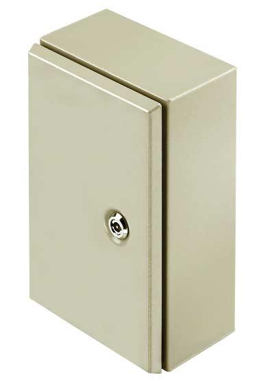
25 STB Range Small Sheet steel enclosures 18
26 STB Range Small Sheet steel enclosures Enclosures from the STB range are typically used as distribution boards and throughout building automation. We recommend the stainless steel versions from this range for the chemical and food industries, due to high demands placed in these fields. Features: 8 sizes with in two material designs Lid with 4 hexagonal M 6 slotted-head screws Earth studs Fixing lugs Our assembly service can supply these enclosures preassembled with terminals and cable glands according to customer requirements. Technical data Material Sheet steel 1.5 mm Stainless steel mm Finish Painted Light grey, semi gloss textured, similar to RAL7032 Stainless steel Polished, chemically dipped Gasket Sizes 1-4: chloroprene Sizes 5-6: silicon HT800 Lid fixing 4 captive hexagonal head, slotted M 6 screws Earthing M 6 earth studs made of brass Enclosure mounting External brackets with 8 mm drillings Equipment mounting TAS 20 rail welded to enclosure base Protection class IP 66 Impact resistance 7 J Temperature range -20 C to + 85 C STB Range Special versions Finish Equipment Sizes Special colours according to customer requirements Assembled according to customer requirements with terminals and cable glands Openings without threads according to customer requirements Special sizes according to customer requirements Approvals ATEX KEMA00ATEX8500 X Ordering information Type Length x Width x Depth Interior height RAL 7032 Stainless steel Weight (Stainl. steel) mm mm Cat. No. Cat. No. g STB x 120 x ,400 STB x 120 x ,550 STB x 150 x ,900 STB x 150 x ,960 STB x 190 x ,000 STB x 250 x ,700 STB x 380 x ,700 STB x 400 x ,400 Accessories Lock nuts Type Cat. No. Sliding fixing nut M5 with screw for TS 32 and TS 35 SFNS Sliding fixing nut M5 with screw for for TS 15 SFNS Sliding fixing nut M3 with screw for terminal strips SFNS M 6 earthing rod nut, brass M See appendix, page 78 19
27 K Range Aluminium enclosures 20
28 K Range Aluminium enclosures K Range enclosures offer a high resistance against environmental influences in industry and transportation. They offer numerous options for applications, for example, for assembling terminals, switches, power supplies, operating and display elements and electronics. Features: 22 sizes in 2 designs Lid with stainless steel screws Earthing screw inside Mounting holes outside of sealed area Mounting thread for mounting rails and mounting plates Our assembly service can supply these enclosures preassembled with terminals and cable glands according to customer requirements. Technical data Material High quality aluminum alloy (Al-Si12) Finish Smooth untreated Silver grey semi gloss textured similar to RAL 7001, 40µm Paint thickness Gasket Neoprene Lid fixing K0, K01, K02, K1, K11; Stainless steel-(+/-)-screws M 4 K2, K21, K3, K31, K32, K4 Earthing (internal) K0, K01, K02, K1, K2, K11, Earthing screw M4 K21, K3, K31, K32 K4, K5, K6, K7, K8 Earthing screw M5 K41, K51, K52, K61, K71, K72, K81 Earthing screw M6 Enclosure mounting K0, K01, K02, K1, K11, K2, K21, K3, K31, K32 Holes M4 K4 Holes M5 K41, K5, K51, K52, K6, K61, K7, K71, K72, K8, K81 Holes M6 Equipment mounting K0, K01, K02, K1, K2, K3 2 threaded holes M3 K11, K21, K31, K32 2 threaded holes M4 K4, K5, K6, K7, K8 2 threaded holes M5 K41, K51, K52, K61, K71, K72, K81 M6 threaded holes Protection class IP 66 and IP 67 Impact resistance 7 J Temperature range -30 C to +80 C K Range Special versions Finish Equipment Gaskets Special colours according to customer requirements Assembled according to customer requirements with terminals and cable glands Drillings according to customer requirements EPDM, Viton Approvals ATEX KEMA00ATEX8501 X 21

29 K Range Ordering information Type Width x Length x Depth Interior height Untreated RAL 7001 Weight mm mm Cat. No. Cat. No. g K 0 45 x 50 x K x 58 x K x 98 x K 1 70 x 70 x K x 75 x K 2 70 x 100 x K x 125 x K 3 70 x 165 x K x 175 x K x 250 x K 4 82 x 130 x / 66.5* K x 122 x K x 170 x ,500 K x 220 x ,410 K x 160 x ,410 K x 200 x / 82* ,040 K x 260 x ,960 K x 350 x / 94* ,741 K x 280 x / 103* ,925 K x 400 x / 101* ,870 K x 585 x / 91.5* ,030 K x 404 x / 101* ,310 * see dimensions diagrams Accessories Mounting plate 2.03-mm galvanized sheet steel Type Cat. No. Type Cat. No. MP K MP K MP K MP K MP K MP K MP K MP K MP K MP K MP K MP K MP K MP K MP K MP K MP K MP K MP K Earthing Rails Enclosure type Horizontal Rails Vertical Rails Cat. No. Pole Cat. No. Pole K K K K K K K K K K K Enclosure types K0, K01 and K02 are designed for use without mounting plates Enclosures K0 to K4 are designed for use without earthing rails Stand-off pillars M6 (Set with 2 pieces) Type Cat. No. Length in mm SP SP SP See appendix Page 82 Exterior fixing lugs (stainless steel, set with 4 pieces) Type Cat. No. available for Enclosures MF set K4, K5, K6, K7, K8 MF set K41, K51, K61, K71, K72, K81 Enclosures K 01, K 02, K 1, K 11, K 2, K 21, K 3, K 31, K 32 are not intended for use with fixing lugs. 22
30 K Range Accessories External hinges The hinges can be delivered separately or assembled. The protection class is retained when correctly mounted. The hinges allow the lids to be opened up to 185. A hinge set is composed of an enclosure hinge, drillings and mounting template, O-rings and appropriate screws. Type Material Cat. No. Hinge set Die-cast aluminium Enclosure type Number of hinges A + B C + D K K K K K K K K K K K K K K K K Enclosures K0, K01, K02, K1, K2, and K3 are not intended for use with hinges. K Range 23

31 POK Range Polyester enclosures 24
32 POK Range Polyester enclosures The POK Range of glass fibre reinforced polyester enclosures are a high quality, reasonably priced solution for electrical connections. The enclosures are suitable for applications where corrosion resistance and impact resistance as well as a high protection class are required. Features: 17 sizes Lid with stainless steel screws Mounting holes outside of sealed areas Mounting thread for mounting rails and mounting plates Our assembly service can supply these enclosures preassembled with terminals and cable glands according to customer requirements. Technical data Material Glass-fibre reinforced polyester (plastic fibres in accordance with DIN 16913) Finish Natural grey, similar RAL 7001 Gasket Chloroprene + Polyurethane Lid fixing POK stainless steel-(+/-)- head screws M4 POK Stainless steel-(+/-)- head screws M6 Enclosure mounting POK holes M4 POK holes M6 Protection class IP 66 Impact resistance 7 J Temperature range -40 C to +90 C Surface resistance > Ohm Flammability UL94 V-0 Toxicity Halogen and cadmium free Special versions EMC Equipment Approvals ATEX on request Shielded for applications that require electromagnetic compatibility Assembled according to customer requirements with terminals and cable glands POK Range 25
33 POK Range Ordering information Type Length x Width x Depth Interior height Cat. No. Weight mm mm g POK 1 75 x 80 x POK 2 75 x 110 x POK 3 75 x 160 x POK x 190 x POK x 230 x POK x 122 x POK x 220 x ,060 POK x 160 x ,290 POK x 260 x ,710 POK x 360 x ,150 POK x 560 x ,185 POK x 255 x ,650 POK x 400 x ,650 POK x 600 x ,235 POK x 400 x ,580 POK x 255 x ,275 POK x 400 x ,800 Accessories Mounting plate 2.03 mm galvanized sheet steel Enclosure Types Cat. No. Enclosure Types Cat. No. POK POK POK POK POK POK POK POK POK POK POK POK POK POK POK POK POK Earthing rails Enclosure Types Horizontal Rails Vertical Rails Cat. No. Pole Cat. No. Pole POK POK POK POK POK POK POK POK POK POK POK POK Enclosures POK1 to POK32 are not intended for use with earthing rails Stand-off pillars M6 (set with 2 pieces) Type Cat. No. Length in mm SP SP SP See appendix Page 96 26

34 POK Range Accessories External hinges The hinges can be delivered separately or assembled. The protection class is retained when correctly mounted. The hinges allow the lids to be opened up to 185. A hinge set is composed of an enclosure hinge, drillings and mounting template, O-rings and appropriate screws. Type Material Cat. No. Hinge set Die-cast aluminium Enclosure type Number of Hinges A + B C + D POK POK POK POK POK POK POK POK POK POK POK POK POK POK POK POK POK POK Range 27

35 TBF Range Polyester enclosures 28
36 TBF Range Polyester enclosures The enclosure range, with the TBFP variant, are manufactured from extremely robust glass-fibre reinforced polyester. They are ideal enclosures for applications where both low weight and at the same time high impact resistance are required. The weather-resistant enclosures TBF/TBFP are suitable for a wide spectrum of applications. Together with the extensive range of accessories, they provide a universal solution for accomodating built-in components such as controlling devices, measuring instruments, valves and other such devices. Features: 9 sizes in 2 designs Lid with nylon screws Mounting holes outside of sealed areas Mounting thread for mounting rails and mounting plates Extensive range of accessories Our assembly service can supply these enclosures preassembled with terminals and cable glands according to customer requirements. Technical data Material TBF 1-7 Enclosures and lids made from glass-fibre reinforced polyester (GRP) TBFP 1-7 base made from glass-fibre reinforced polyester (GRP), lid from polycarbonate (PC) Finish Grey, similar to RAL 7036 Gasket Polyurethane Lid fixing 4 or 6 captive slotted/recessed head nylon screws Equipment mounting 4 or 6 clamping screw M4 Protection class TBF 1-7 IP 67 TBFP 1-7 IP 66 Impact resistance TBF J TBFP J Temperature range TBF -50 C to C TBFP -50 C to +130 C Flammability GRP UL 94 HB PC V2 Toxicity Halogen free Additional features Hinges Extension frames External brackets Reduction of protection class possible! Reduction of protection class possible! Special versions Equipment Available assembled according to customer requirements with terminals, cable glands. earthing plates, earthing rods, display windows, lid hinges and locks. Approvals Ex BAS Ex 92C3393X TBF Range 29


37 TBF Range Ordering information Type Length x Width x Depth Interior height Grey lid Transparent lid Weight mm mm Cat. No. Cat. No. g TBF 19/15/ x 151 x ,055 TBF 19/15/ x 151 x TBF 30/19/ x 186 x ,750 TBF 30/19/ x 186 x ,410 TBF 30/30/ x 302 x ,270 TBF 30/30/ x 302 x ,970 TBF 37/30/ x 302 x ,900 TBF 37/30/ x 302 x ,370 TBF 49/30/ x 302 x ,760 TBF 49/30/ x 302 x ,260 TBF 56/30/ x 302 x ,970 TBF 56/30/ x 302 x ,500 TBF 60/30/ x 302 x ,380 TBF 60/30/ x 302 x ,900 TBF 60/37/ x 372 x ,350 TBF 60/37/ x 372 x ,880 TBF 60/60/ x 603 x ,400 TBF 60/60/ x 603 x ,900 Accessories Mounting plates Extension frames (glass-fibre reinforced Stand-off pillars Zinc coated mild steel polyamide PA66) Type Thickness Cat. No. Type Depth Cat. No. Length Ø A & B Cat. No. VPE (mm) MP TBF 19/ EF TBF 19/ M MP TBF 30/ EF TBF 30/ M MP TBF 30/ EF TBF 30/ M MP TBF 37/ EF TBF 37/ M MP TBF 49/ EF TBF 56/ M MP TBF 56/ EF TBF 60/ M MP TBF 60/ EF TBF 60/ M MP TBF 60/ EF TBF 60/ M MP TBF 60/ M See appendix page
38 TBF Range Accessories Earth continuity plates, brass 3mm Earth continuity plates must be connected to the internal earth point of the enclosure. Type Page Cat. No. Weight Page Cat. No. Weight EP TBF 19/15 C & D A & B EP TBF 30/19 C & D A & B EP TBF 30/30 C & D A & B EP TBF 37/30 C & D A & B EP TBF 49/30 C & D A & B EP TBF 56/30 C & D (2x) A & B EP TBF 60/30 C & D (2x) A & B EP TBF 60/37 C & D (2x) A & B EP TBF 60/60 C & D (2x) A & B (2x) Earth studs Type Cat. No. Weight (g) Type Cat. No. Weight (g) M6 Brass M6 Stainless steel M10 Brass M10 Stainless steel External brackets Type Cat. No. 4 pieces per set made of glass-fibre reinforced polyamide Direct mounting using the four corner holes of the enclosure. If a mounting frame is used, the wall brackets must be mounted before the frame. Maximum permissible equipment weight: 150 kg External Assembly Direct Assembly TBF Range 31


39 MPC Range Small to medium sized polycarbonate enclosures 32


40 MPC Range Small to medium sized polycarbonate enclosures The MPC range of polycarbonate enclosures is particularly suitable for the installation of electrical, electromechanical, and pneumatic devices as well as PCBs. The enclosures are suitable for use in mechanical and chemical applications in demanding environments. Features: 9 sizes in 2 designs Greay or transparent lid Lid with sealing holes Mounting holes outside of sealed areas Mounting thread for mounting rails and mounting plates Extensive range of accessories Our assembly service can supply these enclosures preassembled with terminals and cable glands according to customer requirements. Technical data Material Polycarbonate Lid Transparent or grey Finish Grey, similar to RAL 7035 Gasket Polyurethane foam Lid fixing 4 recessed screws (polyamide) Enclosure mounting 4 Holes Ø 4.5 or external fixing lugs (accessories) Equipment mounting Self tapping screws Protection class IP 66 and IP 67 Temperature range -50 C to +130 C Approvals ATEX on request MPC Range 33

41 MPC Range Ordering information Type Length x Width x Depth Interior height Grey lid Transparent lid Weight mm mm Cat. No. Cat. No. g MPC 07/12/07 75 x 125 x MPC 07/12/12 75 x 125 x MPC 12/12/ x 125 x MPC 12/17/ x 175 x MPC 12/17/ x 175 x MPC 12/17/ x 175 x MPC 17/17/ x 175 x MPC 17/17/ x 175 x MPC 17/25/ x 250 x Accessories Mounting plates made of galvanized sheet steel Type Cat. No. MP MPC 07/ MP MPC 12/ MP MPC 12/ MP MPC 17/ MP MPC 17/ Fixing lugs (set with 4 pieces) Type Cat. No. MF MPC Mounting screws Type Cat. No. SC MPC Hinge set Type Cat. No. HG MPC See appendix page
42 35 MPC Range

43 FPC Range Medium sized polycarbonate enclosures 36


44 FPC Range Medium sized polycarbonate enclosures FPC Range The design of the FPC range of enclosures is based on the MPC range. The FPC range of enclosures has the same material characteristics as the Mpc range plus a more extensive assortment of accessories; thus increasing the amount of applications. Features: 6 sizes in 2 designs Grey or transparent lid Lid with sealing holes Mounting holes outside of sealed areas Mounting thread for mounting rails and mounting plates Extensive range of accessories Our assembly service can supply these enclosures preassembled with terminals and cable glands according to customer requirements. Technical data Material Polycarbonate Lid Transparent or grey Finish Grey, similar to RAL 7035 Gasket Polyurethane foam Lid fixing 4 recessed screws (polyamide Enclosure mounting 4 Holes Ø 7.5 or external fixing lugs (Accessories) Equipment mounting Self tapping screws Protection class IP 66 and IP 67 Temperature range -50 C to +130 C Approvals ATEX on request 37
45 FPC Range Ordering information Type Length x Width x Depth Interior height Grey lid Transparent lid Weight mm mm Cat. No. Cat. No. g FPC 20/20/ x 200 x ,039 FPC 20/30/ x 300 x ,349 FPC 20/40/ x 400 x ,674 FPC 30/30/ x 300 x ,738 FPC 30/40/ x 400 x ,199 FPC 40/60/ x 600 x ,964 Accessories Mounting plates made of galvanized sheet steel Type Cat. No. MP FPC 20/ MP FPC 20/ MP FPC 20/ MP FPC 30/ MP FPC 30/ MP FPC 40/ Extension frames Type Cat. No. EF FPC 20/ mm hoch EF FPC 20/ mm hoch EF FPC 20/ mm hoch EF FPC 30/ mm hoch EF FPC 30/ mm hoch EF FPC 40/ mm hoch Hinge set Type Cat. No. HG FPC Fixing lugs (set with 4 pieces) Type Cat. No. MF FPC Display window Type Cat. No. WK FPC mm x 59 mm WK FPC mm x 94 mm WK FPC mm x 130 mm WK FPC mm x 163 mm WK FPC mm x 200 mm See appendix Page
46 39 FPC Range

47 GPS Range Polystyrene enclosures 40
48 GPS Range Polystyrene enclosures The GPS range of enclosures is the universal and reasonably priced solution for indoor applications. Features: 9 sizes in 4 designs Grey or transparent lid Sides with or without openings Lid with sealing holes Mounting holes outside of sealed areas GPS Range Our assembly service can supply these enclosures preassembled with terminals and cable glands according to customer requirements. Technical data Material Polystyrene Finish Grey, similar to RAL 7035 Gasket Polyurethane Lid Grey: polystyrene Transparent: polycarbonate Lid fixing 4 recessed screws made from polyamide Enclosure mounting 4 holes or via external lugs (accessories) Equipment mounting Self tapping screws (accessories) Protection class IP66 Max. Temperature range -40 C to 70 C Flammability V - 2 according to UL94 Approvals ATEX on request 41


49 GPS Range Ordering information With knockout Without knockout Type Length x Width x Depth Interior height Grey Transparent Grey Transparent mm mm Cat. No. Cat. No. Cat. No. Cat. No. GPS 07/07/06 65 x 65 x GPS 09/07/06 94 x 65 x GPS 11/11/ x 110 x GPS 11/11/ x 110 x GPS 13/09/ x 94 x GPS 13/13/ x 130 x GPS 18/11/ x 110 x GPS 25/18/ x 180 x GPS 36/25/ x 254 x Accessories Mounting plates Type Cat. No. MP GPS 07/ MP GPS 09/ MP GPS 11/ MP GPS 13/ MP GPS 13/ MP GPS 18/ MP GPS 25/ MP GPS 36/ Mounting screws Type Cat. No. SC GPS Spacer between enclosure base and side (set with 4 pieces) Type Cat. No. SP GPS Fixing lugs (set with 4 pieces) Type Cat. No. MF GPS Hinge set Type Cat. No. HG GPS small (to GPS 13/15/08) HG GPS large (from GPS 18/11/09) Stand-off pillars Hinge set See appendix Page
50 43 GPS Range

51 Cable glands 44
52 Cable glands The European Technical Standard DIN EN Metric cable glands for electric installations - the end of the PG Cable glands threads. The technical standards Cable Glands for cables and conductors with PG standard threads DIN (P1 - P4), DIN 46255, DIN 46259, DIN and DIN VDE 0619 became invalid on the 31 December Cable glands with PG threads are no longer standard. The design approvals granted in accordance with DIN VDE 0619: remained valid until The European Standard Metric Cable Glands for Electrical Installations EN became valid on The EN Standard EN is mandatory in all member countries of the European Union (EU) and associated countries collaborating with CENELEC (European Committee For Electrotechnical Standardization) who adopt the standard. That means that only metric cable glands are permitted to be used in new constructions as of in those countries described above. We offer cable glands as a well balanced assortment for different applications. Cable glands made from plastic and brass EMC cable glands For hazardous areas in accordance with EN 50014, EN and ATEX VDE, CSA and UL approved Cable entries, for example for enclosures or heavy duty connectors can be easily and reliably installed. DIN protection classes: IP 54 Protection against dust accumulation as well as protection against water splash IP 65 Protection against dust inflow as well as protection against hose water IP 66 Protection against dust inflow as well as protection in the case of overflooding IP 68 Protection against dust inflow as well as protection when submerging IP 69 Protection against water under pressure Cable Glands Labelling of explosion protected electric equipment according to old Ex approvals. Name of Type Examination Symbol for Conformity to Risk of Abbreviation Group of manufacturer designation certificate number electrical equipment european explosion of protection electrical or logo from of EU test site certified by standards classes used devices manufacturer EU test site certified 16 T E Ex e II i 45
53 Cable glands Labeling of devices and protection systems according ATEX The following information must be clearly and permanently readable on every device and protection system: Example: Name of Type/size Number of Symbol of Symbol of Conformity to Risk of Abbreviation Device manufacturer designation EU-type-examination protection device european explosion of applied group or from test certificate from group and standards type of logo manufacturer EU test site explosion category certified protection classes T II 2 G E EX e II ia Cable glands with metric connection thread With the taking of effect of European standard EN metric cable glands for electric installation the Europe-wide introduction of the metric ISO fine thread in cable glands took place on The EN standard lists the individual thread sizes. The previously-known thread sizes PG 7 to PG 48 (10 sizes) were replaced by the metric sizes M 12 to M 63 (8 sizes). This catalogue contains a large selection of metric cable glands Ex cables and cable entries for use in hazardous areas. 46
54 Cable glands Cable glands Criteria for the selection of cable glands Type ADE Define the installation area, in which you want to use the glands Define the cable types to determine the requested functions Check the dimensions of the outer cable sheath Check the size and type of reinforcement Check the dimensions of the inner cable sheath Check the dimensions of the lead sheath Determine the environmental condition Check the accessories Installation instructions for endangered areas in accordance with the Standards CENELEC EN Increased safety to Standard EN 50019; direct thread insertion into the enclosure or with a lock nut. Unused insertions have to be closed with a certified stopping plug. Flame protected in accordance with EN 50018; direct thread insertion into the enclosure with five full pitches (approx. 8 mm); Unused insertion have to be closed with a certified stopping plug. Cable Glands Armoured cable Non-armoured cable A: Inner sheath B: Lead sheath C:Armouring (steel strip / SWA / braided) D: Outer sheath Cable glands for armoured cable E: Outer sheath Cable glands for non-armoured cable 1: Gland 2: Sealing washer for inner cable sheath 3: Clamping module / Earthing of armouring 4: Base 5: Sealing washer for outer cable sheath 6: Washers 7: Union nut 1: Gland 2: Clamping module 3: Sealing washer 4: Union nut 1: Gland 2: Sealing washer 3: Washer 4: Union nut 47
55 Cable glands Plastic IP54 Plastic IP68 L L L1 L1 Thread Thread a v Reasonably priced cable glands IP 54 Plastic cable glands IP68; VDE, CSA and UL tested; halogene-free. EN 50262: metric Technical data Material: Polyamide connection thread M Polystyrene connection thread PG Sealing: Soft rubber Temperature: -20 C C Protection class: IP54 (with thread sealing ring type GWDR...-PO = IP65) Colour: similar grey RAL 7035 Technical data Material: Polyamide Sealing: Neoprene Temperature: -40 C C (peak +100 C) Protection class: IP68 / 5 bar in the stated clamping range with GWDR Colour: similar grey RAL 7035 Ordering data Type Thread Clamp range L L1 SW1/SW2 Qty. Cat. No. Metric gland plastic IP54 VGM12-K54 M 12 x / VGM16-K54 M 16 x / VGM20-K54 M 20 x / VGM25-K54 M 25 x / VGM25-K54 M 25 x / VGM32-K54 M 32 x / VGM40-K54 M 40 x / VGM50-K54 M 50 x / VGM63-K54 M 63 x / PG gland plastic IP54 VG 7-K54 PG / VG 9-K54 PG / VG 11-K54 PG / VG 13.5-K54 PG / VG 16-K54 PG / VG 21-K54 PG / VG 29-K54 PG / VG 36-K54 PG / VG 42-K54 PG / VG 48-K54 PG / Ordering data Type Thread Clamp range L L1 SW Qty. Cat. No. Metric gland plastic Approval: VDE VG M 12 - K 68 M 12 x VG M 16 - K 68 M 16 x VG M 20 - K 68 M 20 x VG M 25 - K 68 M 25 x VG M 32 - K 68 M 32 x VG M 40 - K 68 M 40 x VG M 50 - K 68 M 50 x VG M 63 - K 68 M 63 x PG gland plastic Approval: VDE/UL VG 7-K68 PG VG 9-K68 PG VG 11-K68 PG VG 13.5-K68 PG VG 16-K68 PG VG 21-K68 PG VG 29-K68 PG VG 36-K68 PG VG 42-K68 PG VG 48-K68 PG NPT gland plastic Approval: UL/CSA VG NPT 3/8" 5-10-K 68 NPT 3/8" VG NPT 1/2" 6-12-K 68 NPT 1/2" VG NPT 1/2" K 68 NPT 1/2" VG NPT 3/4" K 68 NPT 3/4" VG NPT 1" K 68 NPT 1" all sizes in mm all sizes in mm 48
56 Cable glands Cable glands brass IP54 Cable glands brass IP68 L L L1 Cable Glands Thread Thread L1 Brass cable gland with hexagon threaded glands Brass cable gland IP68 with strain relief. Reduced clamping range on request. Multiple seal insert on request. Technical data Technical data Material: Sealing: Temperature: Protection class: Nickel plated brass Soft rubber -20 C C IP54 (with thread sealing ring Type GWDR...-PO = IP65) Material: Sealing: Temperature: Protection class: Nickel plated brass Neoprene -40 C C (peak +100 C) IP 68 / 5 bar with GWDR in the clamping area Ordering data Ordering data Type Thread Clamp range L L1 SW1/SW2 Qty. Cat. No. Metric gland brass IP 54, hexagonal VGM12-MS54 M 12 x / VGM12-MS54 M 12 x / VGM16-MS54 M 16 x / VGM20-MS54 M 20 x / VGM20-MS54 M 20 x / VGM25-MS54 M 25 x / VGM25-MS54 M 25 x / VGM32-MS54 M 32 x / VGM40-MS54 M 40 x / VGM50-MS54 M 50 x / VGM50-MS54 M 50 x / VGM63-MS54 M 63 x / PG gland brass IP 54, hexagonal VG 7-MS54 PG / VG 9-MS54 PG / VG 11-MS54 PG / VG 13.5-MS54 PG / VG 16-MS54 PG / VG 21-MS54 PG / VG 29-MS54 PG / VG 36-MS54 PG / VG 42-MS54 PG / VG 48-MS54 PG / Type Thread Clamp range L L1 SW Qty. Cat. No. Metric gland brass VG M 12 - MS 68 M 12 x VG M 16 - MS 68 M 16 x VG M 20 - MS 68 M 20 x VG M 25 - MS 68 M 25 x VG M 32 - MS 68 M 32 x VG M 40 - MS 68 M 40 x VG M 50 - MS 68 M 50 x VG M 63 - MS 68 M 63 x PG gland brass IP 68 VG 7-MS68 PG VG 9-MS68 PG VG 11-MS68 PG VG 13.5-MS68 PG VG 16-MS68 PG VG 21-MS68 PG VG 29-MS68 PG VG 36-MS68 PG VG 42-MS68 PG VG 48-MS68 PG NPT gland brass VG NPT 3/8" - MS 68NPT 3/8" VG NPT 1/2" - MS 68NPT 1/2" VG NPT 3/4" - MS 68NPT 3/4" all sizes in mm all sizes in mm 49


57 Cable glands Plastic cable glands with bending protection Cable glands brass with bending protection L L Thread Thread L1 L1 Cable gland with bending protection and internal strain relief.clamping profile made of Hostaform C. Cable gland with bending protection and internal strain relief. Without external strain relief clamp. Clamping profile made of Hostaform C. Technical data Material: Polyamide, glass fibre reinforced Sealing: Soft rubber Temperature: -10 C C Protection class: IP 65 Colour: similar Grey RAL 7035 Technical data Material: Nickel plated brass Sealing: Soft rubber Temperature: -10 C C Protection class: IP 65 Ordering data Type Thread Clamp range L L1 SW Qty. Cat. No. Metric KV cable gland plastic bending protection VGM12-K65 BS M 12 x VGM16-K65 BS M 16 x VGM20-K65 BS M 20 x VGM20-K65 BS M 20 x VGM25-K65 BS M 25 x VGM25-K65 BS M 25 x VGM32-K65 BS M 32 x Ordering data Type Thread Clamp range L L1 SW1/SW2 Qty. Cat. No. PG-KV cable gland Brass bending protection VG 9-MS65 BS PG / VG 11-MS65 BS PG / VG 13.5-MS65 BS PG / VG 16-MS65 BS PG / VG 21-MS65 BS PG / VG 29-MS65 BS PG / PG-KV plastic bending protection VG 7-K65 BS PG VG 9-K65 BS PG VG 11-K65 BS PG VG 13.5-K65 BS PG VG 16-K65 BS PG VG 21-K65 BS PG VG 29-K65 BS PG all sizes in mm all sizes in mm 50

 Material: Sealing: Temperature: Protection class: Nickel plated brass Neoprene -20 C... +100 C IP66 (with thread sealing ring Type GWDR.")

58 Cable glands Cable glands brass IP54 with gripping jaw Cable glands brass for Ex-areas L L L1 Thread Thread L1 T With cantered strain relief For use in hazardous areas. These cable glands are tested for higher safety specifications with certified conformity to approvals LCIE 97ATEX6005X. Variant for EMC applications are available. Cable Glands Technical data Technical data Material: Sealing: Temperature: Protection class: Nickel plated brass Universal sealing ring neoprene -30 C C IP54 (with thread sealing ring type GWDR...-PO = IP65) Material: Sealing: Temperature: Protection class: Nickel plated brass Neoprene -20 C C IP66 (with thread sealing ring Type GWDR...-NP = IP68/20 bar) ATEX certification available Ordering data Ordering data Type Thread Clamp range L L1 SW1/SW2 Qty. Cat. No. Metric gland brass IP 54, hexagonal VG M12-MS54ZE M 12 x VG M12-MS54ZE M 12 x VG M16-MS54ZE M 16 x VG M20-MS54ZE M 20 x VG M20-MS54ZE M 20 x VG M25-MS54ZE M 25 x VG M25-MS54ZE M 25 x VG M32-MS54ZE M 32 x VGM40-MS54ZE M 40 x VG M50-MS54ZE M 50 x VG M50-MS54ZE M 50 x VG M63-MS54ZE M 63 x PG gland brass IP 54, hexagonal VG 7-MS54-ZE PG / VG 9-MS54-ZE PG / VG 11-MS54-ZE PG / VG 13.5-MS54-ZE PG / VG 16-MS54-ZE PG / VG 21-MS54-ZE PG / VG 29-MS54-ZE PG / VG 36-MS54-ZE PG / VG 42-MS54-ZE PG / VG 48-MS54-ZE PG / Type Thread Clamp range L L1 SW Qty. Cat. No. Metric gland brass-kv for Eex-e VG M 16-Exe MS M 16 x VG M 20-Exe MS M 20 x VG M 25-Exe MS M 25 x VG M 32-Exe MS M 32 x VG M 40-Exe MS M 40 x VG M 50-Exe MS M 50 x VG M 63-Exe MS M 63 x PG gland brass-kv for Eex-e VG 7-Exe MS PG VG 9-Exe MS PG VG 11-Exe MS PG VG 13.5-Exe MS PG VG 16-Exe MS PG VG 21-Exe MS PG VG 29-Exe MS PG VG 36-Exe MS PG VG 42-Exe MS PG VG 48-Exe MS PG NPT brass KV for Eex-e VG NPT 1/2" Eex-e MS NPT 1/2" VG NPT 3/4" Eex-e MS NPT 3/4" VG NPT 1" Eex-e MS NPT 1" VG NPT 1 1/4" Eex-e MS NPT 1 1/4" VG NPT 1 1/2" Eex-e MS NPT 1 1/2" VG NPT 2" Eex-e MS NPT 2" VG NPT 2 1/2" Eex-e MS NPT 2 1/2" all sizes in mm all sizes in mm 51
59 Cable glands Plastic cable glands for EExe-areas Plastic cable glands for EExi-areas L L L1 L1 Thread Thread T T For use in hazardous areas (EEX e II). These cable glands are tested for higher safety specifications with certified conformity to approvals LCIE 97ATEX6007X. The clamping profile serves as an internal strain relief. The sealing ring is constructed with a membrane against dust, which can be easily pierced. For use in explosion endangered areas (EEX i). These cable glands are tested for higher safety specifications with certified conformity to approvals LCIE 97ATEX6007X. The clamping profile is used as an internal strain relief. The sealing ring is constructed with a membrane against dust, which can be easily pierced. Technical data Material: Polyamide Sealing: Santoprene Temperature: -40 C C Protection class: IP66 (with thread sealing ring) Type GWDR...-NP = IP68/5 bar) ATEX available Colour: similar Black RAL 9005 Ordering data Type Thread Clamp range L L1 SW Qty. Cat. No. Metric plastic cable glands for EExe-areas VG M 16-Exe SW M 16 x VG M 20-Exe SW M 20 x VG M 25-Exe SW M 25 x VG M 32-Exe SW M 32 x VG M 40-Exe SW M 40 x VG M 50-Exe SW M 50 x VG M 63-Exe SW M 63 x Technical data Material: Polyamide Sealing: Santoprene Temperature: -40 C C Protection class: IP66 (with thread sealing ring) Type GWDR...-NP = IP68/5 bar) ATEX granted Colour: similar Blue RAL 5012 Ordering data Type Thread Clamp range L L1 SW Qty. Cat. No. PG plastic cable glands for EExi-areas VG M 16-Exi BL M 16 x VG M 20-Exi BL M 20 x VG M 25-Exi BL M 25 x VG M 32-Exi BL M 32 x VG M 40-Exi BL M 40 x VG M 50-Exi BL M 50 x VG M 63-Exi BL M 63 x / PG plastic cable glands for EExe-areas VG 7-Exe SW PG VG 9-Exe SW PG VG 11-Exe SW PG VG 13.5-Exe SW PG VG 16-Exe SW PG VG 21-Exe SW PG VG 29-Exe SW PG VG 36-Exe SW PG VG 42-Exe SW PG VG 48-Exe SW PG PG plastic cable glands for EExi-areas VG 7-Exi BL PG VG 9-Exi BL PG VG 11-Exi BL PG VG 13.5-Exi BL PG VG 16-Exi BL PG VG 21-Exi BL PG VG 29-Exi BL PG VG 36-Exi BL PG VG 42-Exi BL PG VG 48-Exi BL PG all sizes in mm all sizes in mm 52

 Protection class: IP 68 / 5 bar with GWDR Technical data Material: Nickel plated brass (on request stainless steel) Sealing: Neoprene Temperature: -40 C - 100 C Protection class:")


60 Cable glands Plastic cable glands with strain relief spiral cap Cable Gland ADE 1F T Cable gland specially for moveable connections.; Approvals to VDE and UL; halogen-free. Reduced clamping range on request EN 50262: metric For use in hazardous areas EEx e II, EEx d IIB, EEx d II C 2000 cm 3 These cable glands are certified in accordance with LCIE 97ATEX6008X. Cable Glands Technical data Material: Polyamide 6 Sealing: Neoprene Temperature: -40 C C (peak 150 C) Protection class: IP 68 / 5 bar with GWDR Technical data Material: Nickel plated brass (on request stainless steel) Sealing: Neoprene Temperature: -40 C C Protection class: IP 68 (10 bar) ATEX available Colour: similar grey RAL 7035 (on request 9005) Ordering data Type Thread Clamp range L L1 SW Qty. Cat. No. Metric.plastic-KV with strain relief spiral cap VGM12-K68 SKS M 12 x VGM16-K68 SKS M 16 x VGM20-K68 SKS M 20 x VGM20-K68 SKS M 20 x VGM25-K68 SKS M 25 x PG plastic cable glands with strain relief spiral cap VG 7-K68 SKS PG VG 9-K68 SKS PG VG 11-K68 SKS PG VG 13.5-K68 SKS PG VG 16-K68 SKS PG VG 21-K68 SKS PG Ordering data Type Thread Protecting cap Clamp range L L1 SW1 SW2 Qty. Cat. No. Metric cable glands VG ADE 1/M 12 Exe/d M 12 x VG ADE 1/M 16 Exe/d M 16 x VG ADE 1/M 20 Exe/d M 20 x VG ADE 1/M 25 Exe/d M 25 x VG ADE 1/M 32 Exe/d M 32 x VG ADE 1/M 40 Exe/d M 40 x VG ADE 1/M 50 Exe/d M 50 x VG ADE 1/M 63 Exe/d M 63 x VG ADE 1/M 75 Exe/d M 75 x VG ADE 1/M 80 Exe/d M 80 x VG ADE 1/M 90 Exe/d M 90 x VG ADE 1/M 100 Exe/d M 100 x all sizes in mm all sizes in mm 53


61 Cable glands ADE 4F EMC cable glands L L SW 1 SW 2 L1 Thread T For use in hazardous areas: EEx e II, EEx d IIB, EEx d II C 2000 cm 3 These cable glands are certified in accordance with LCIE 97ATEX6008X. On request: silicone sealing ring, halogen-free, Working temperature: -70 C C. Technical data Material: Sealing: Nickel plated brass (on request stainless steel) Neoprene Temperature: -40 C C Protection class: IP 68 (10 bar) ATEX available High shielding factor up to 100 db. An endless lock washer is pressed against the cable armour by two conical rings; thus guaranteeing a reliable and safe contact. This ensures that the shield braiding is inserted into the enclosure. Technical data Material: Sealing: O-Ring: Temperature: Nickel plated brass TPE-V /thermoplastic Elastomer Perbunan Protection class: IP C C (peak 150 C) Ordering data Type Thread Sealing Cable Armoured Cable L L1 SW1 SW2 Qty. Cat. No. ring Ø outside Ø inside Metric gland VG ADE 4F/M 12 Exe/d M 12 x VG ADE 4F/M 16 Exe/d M 16 x VG ADE 4F/M 20 Exe/d M 20 x VG ADE 4F/M 25 Exe/d M 25 x VG ADE 4F/M 32 Exe/d M 32 x VG ADE 4F/M 40 Exe/d M 40 x VG ADE 4F/M 50 Exe/d M 50 x VG ADE 4F/M 63 Exe/d M 63 x VG ADE 4F/M 75 Exe/d M 75 x VG ADE 4F/M 80 Exe/d M 80 x VG ADE 4F/M 90 Exe/d M 90 x Ordering data Type Thread Clamp range Armour-Ø L SW Qty. Cat. No. Metric cable glands brass VG EMC M18x1.5 M 18x VG EMC M20x1.5 M 20x VG EMC M24x1.5 M 24x VG EMC M25x1.5 M 25x PG cable gland brass VG EMC Pg 7/9 PG 7 / VG EMC Pg 9/11 PG 9 / VG EMC Pg 11 PG VG EMC Pg 13.5 PG VG EMC Pg 16 PG VG EMC Pg 16 PG VG EMC Pg 21 PG VG EMC Pg 21 PG VG EMC Pg 29 PG VG EMC Pg 29 PG VG EMC Pg 36 PG all sizes in mm all sizes in mm 54

62 Cable glands Lock nut brass Lock nut with EMC S D D Thread Thread Lock nut for securing brass cable glands in accordance with DIN These lock nuts are equipped with six cutting elements, which cut into the painted insulating layer of the enclosure; thus creating an optimum contact. Cable Glands Technical data Technical data Material: Nickel plated brass (on request stainless steel) Material: Nickel plated brass Ordering data Ordering data Type Thread D SW Qty. Cat. No. Metric gland lock nut brass SKMU M 12-MS M 12 x SKMU M 16-MS M 16 x SKMU M 20-MS M 20 x SKMU M 25-MS M 25 x SKMU M 32-MS M 32 x SKMU M 40-MS M 40 x SKMU M 50-MS M 50 x SKMU M 63-MS M 63 x SKMU M 75-MS M 75 x Type Thread D S SW Qty. Cat. No. Metric gland lock nut EMC brass approx. SKMU EMC M10 M 10 x SKMU EMC M12 M 12 x SKMU EMC M16 M 16 x SKMU EMC M20 M 20 x SKMU EMC M25 M 25 x SKMU EMC M32 M 32 x SKMU EMC M40 M 40 x SKMU EMC M50 M 50 x SKMU EMC M63 M 63 x PG gland lock nut brass SKMU Pg7-MS PG SKMU Pg9-MS PG SKMU Pg11-MS PG SKMU Pg13.5-MS PG SKMU Pg16-MS PG SKMU Pg21-MS PG SKMU Pg29-MS PG SKMU Pg36-MS PG SKMU Pg42-MS PG SKMU Pg48-MS PG PG gland lock nut brass with EMC SKMU EMC Pg7 PG SKMU EMC Pg9 PG SKMU EMC Pg11 PG SKMU EMC Pg13.5 PG SKMU EMC Pg16 PG SKMU EMC Pg21 PG SKMU EMC Pg29 PG all sizes in mm all sizes in mm 55

63 Cable glands Lock nut Plastic Lock nut Plastic Ex D D Thread Thread T Lock nut for securing plastic cable glands in accordance with DIN Lock nut for securing cable glands used in Ex-areas in accordance with LCIE 97ATEX6007X. Technical data Material: Polyamide, glass fibre reinforced Temperature: -40 C C Colour: similar grey RAL 7035 DIN: Technical data Material: Polyamide Temperature: -40 C C Colour: similar black RAL 9005 Ordering data Ordering data Type Thread D SW Qty. Cat. No. Metric gland lock nut plastic grey SKMU M12-K GR M 12 x SKMU M16-K GR M 16 x SKMU M20-K GR M 20 x SKMU M25-K GR M 25 x SKMU M32-K GR M 32 x SKMU M40-K GR M 40 x SKMU M50-K GR M 50 x SKMU M63-K GR M 63 x PG gland lock nut plastic grey SKMU Pg7-K GR PG SKMU Pg9-K GR PG SKMU Pg11-K GR PG SKMU Pg13.5-K GR PG SKMU Pg16-K GR PG SKMU Pg21-K GR PG SKMU Pg29-K GR PG SKMU Pg36-K GR PG SKMU Pg42-K GR PG SKMU Pg48-K GR PG Type Thread D SW Qty. Cat. No. Metric gland lock nut plastic Ex SKMU M 16-K SW M 16 x SKMU M 20-K SW M 20 x SKMU M 25-K SW M 25 x SKMU M 32-K SW M 32 x SKMU M 40-K SW M 40 x SKMU M 50-K SW M 50 x SKMU M 63-K SW M 63 x PG gland lock nut plastic Ex SKMU Pg7-K SW PG SKMU Pg9-K SW PG SKMU Pg11-K SW PG SKMU Pg13.5-K SW PG SKMU Pg16-K SW PG SKMU Pg21-K SW PG SKMU Pg29-K SW PG SKMU Pg36-K SW PG SKMU Pg42-K SW PG SKMU Pg48-K SW PG all sizes in mm all sizes in mm 56


64 Cable glands Threaded sealing rings Threaded sealing rings S S D 2 D 2 D 1 D 1 To increase the protection class of cable glands. To increase the protection class of cable glands in Ex areas in accordance with LCIE 97ATEX6007X. Cable Glands Technical data Material: Polyethylene DIN: Technical data Material: Neoprene DIN: Ordering data Type Thread D1 D2 S Qty. Cat. No. Metric threaded sealing rings, polyethylene GWDR M12-PO M 12 x GWDR M16-PO M 16 x GWDR M20-PO M 20 x GWDR M25-PO M 25 x GWDR M32-PO M 32 x GWDR M40-PO M 40 x GWDR M50-PO M 50 x GWDR M63-PO M 63 x PG Threaded sealing rings, polyethylene GWDR Pg7-PO PG GWDR Pg9-PO PG GWDR Pg11-PO PG GWDR Pg13.5-PO PG GWDR Pg16-PO PG GWDR Pg21-PO PG GWDR Pg29-PO PG GWDR Pg36-PO PG GWDR Pg42-PO PG GWDR Pg48-PO PG Ordering data Type Thread D1 D2 S Qty. Cat. No. Metric threaded sealing rings, neoprene GWDR M 16-NP M GWDR M 20-NP M GWDR M 25-NP M GWDR M 32-NP M GWDR M 40-NP M GWDR M 50-NP M GWDR M 63-NP M PG threaded sealing rings, neoprene GWDR Pg7-NP PG GWDR Pg9-NP PG GWDR Pg11-NP PG GWDR Pg13.5-NP PG GWDR Pg16-NP PG GWDR Pg21-NP PG GWDR Pg29-NP PG GWDR Pg36-NP PG GWDR Pg42-NP PG GWDR Pg48-NP PG all sizes in mm all sizes in mm 57

 Colour: similar Grey RAL 7035 DIN: 46320 Material: Sealing: Temperature: Protection class: Nickel plated brass O-Ring Perbunan -40 C.")
65 Cable glands Sealing plug, plastic Sealing plug, brass Ø Ø L1 L1 L L Thread Thread Glass-fibre reinforced polyamide offers excellent resistance to numerous chemicals. Self-sealing version with O-ring made of perbunan. Also available with a hexagon head. Technical data Technical data Material: Polyamide, glass fibre reinforced Temperature: -40 C C Protection class: IP54 (with thread sealing ring Type GWDR...-PO = IP66) Colour: similar Grey RAL 7035 DIN: Material: Sealing: Temperature: Protection class: Nickel plated brass O-Ring Perbunan -40 C C IP65 Ordering data Ordering data Type Thread L L1 Head Ø Qty. Cat. No. Metric sealing plug, plastic VP M12-K54 M12 x VP M16-K54 M16 x VP M20-K54 M20 x VP M25-K54 M25 x VP M32-K54 M32 x VP M40-K54 M40 x VP M50-K54 M50 x VP M63-K54 M63 x PG sealing plug, plastic VP 7-K54 PG VP 9-K54 PG VP 11-K54 PG VP 13.5-K54 PG VP 16-K54 PG VP 21-K54 PG VP 29-K54 PG VP 36-K54 PG VP 42-K54 PG VP 48-K54 PG Type Thread L L1 Head-Ø Qty. Cat. No. Metric sealing plug, brass VP M16 - MS65 M VP M20 - MS65 M VP M25 - MS65 M VP M32 - MS65 M VP M40 - MS65 M VP M50 - MS65 M VP M63 - MS65 M PG sealing plug, brass VP 7-MS65 PG VP 9-MS65 PG VP 11-MS65 PG VP 13.5-K65 PG VP 16-MS65 PG VP 21-MS65 PG VP 29-MS65 PG VP 36-MS65 PG VP 42-MS65 PG VP 48-MS65 PG all sizes in mm all sizes in mm 58
. Approvals in accordance with LCIE 98ATEX0001X. Also available with metric ISO thread.")
 ATEX granted Colour: similar Black RAL 9005 Material: Temperature: Protection class: Nickel plated brass -40 C... +100 C IP54 (with thread sealing ring Type GWDR.")
66 Cable glands Sealing plug plastic EExe Sealing plug brass EExe / EExd L1 L1 Thread Thread T T Sealing plugs for Ex areas in accordance with LCIE 97ATEX6003X. Also available with metric ISO thread Hexagon head version for Ex-areas (EExe II). Approvals in accordance with LCIE 98ATEX0001X. Also available with metric ISO thread. Cable Glands Technical data Technical data Material: Polyamide Temperature: -40 C C Protection class: IP54 (with thread sealing ring Type GWDR...-PO = IP66) ATEX granted Colour: similar Black RAL 9005 Material: Temperature: Protection class: Nickel plated brass -40 C C IP54 (with thread sealing ring Type GWDR...-NP = IP66) ATEX granted Ordering data Ordering data Type Thread L L1 SW Qty. Cat. No. Metric sealing plug, plastic EExe VP M 16-Exe SW M 16 x VP M 20-Exe SW M 20 x VP M 25-Exe SW M 25 x VP M 32-Exe SW M 32 x VP M 40-Exe SW M 40 x VP M 50-Exe SW M 50 x VP M 63-Exe SW M 63 x Type Thread L L1 SW Qty. Cat. No. Metric sealing plug, brass EExe VP M 16-Exe SW M 16 x VP M 20-Exe SW M 20 x VP M 25-Exe SW M 25 x VP M 32-Exe SW M 32 x VP M 40-Exe SW M 40 x VP M 50-Exe SW M 50 x VP M 63-Exe SW M 63 x PG sealing plug, plastic EExe VP 7-Exe SW PG VP 9-Exe SW PG VP 11-Exe SW PG VP 13.5-Exe SW PG VP 16-Exe SW PG VP 21-Exe SW PG VP 29-Exe SW PG VP 36-Exe SW PG VP 42-Exe SW PG VP 48-Exe SW PG PG sealing plug, brass EExe VP 7-Exe MS PG VP 9-Exe MS PG VP 11-Exe MS PG VP 13.5-Exe MS PG VP 16-Exe MS PG VP 21-Exe MS PG VP 29-Exe MS PG VP 36-Exe MS PG VP 42-Exe MS PG VP 48-Exe MS PG all sizes in mm all sizes in mm 59
67 Cable glands Adaptors T Technical data Material: Temperature: Protection class: Approval: Nickel plated brass -40 C C IP54 (with thread sealing ring Type GWDR...-NP = IP66) in accordance with LCIE 97ATEX6001X Metric PG adaptors, available soon. Please contact us Male thread 3 NPT 21/2 NPT 2 NPT 11/2 NPT 11/4 NPT 1 NPT 3/4 NPT 1/2 NPT M 75 M 63 M 50 M 40 M 32 M 25 M 20 M 16 Female thread M M M M M M M M /2 NPT /4 NPT NPT /4 NPT /2 NPT NPT /2 NPT NPT


68 Cable glands Stopper Seal stopper Accessories Earthing washer, brass for lead-sheathed cables L1 Thread Mounting instructions Closed version which can be can also be used as as a simple sealing plug In order to improve conductivity, the earthing washer is inserted into the cable gland when using lead-sheathed cables. Please refer to the mounting instructions. Cable Glands Technical data Technical data Material: Polyethylene Temperature: -20 C C Protection class: IP 54 Colour: similar grey RAL 7035 Material: brass Ordering data Ordering data Type Thread L1 Qty. Cat. No. PG seal stopper DN Pg9 PG DN Pg11 PG DN Pg13.5 PG DN Pg16 PG DN Pg21 PG DN Pg29 PG DN Pg36 PG DN Pg42 PG DN Pg48 PG Type Cable Ø D L Qty. Cat. No. EA VS No EA VS No EA VS No EA VS No EA VS No EA VS No EA VS No EA VS No EA VS No EA VS No EA VS No all sizes in mm all sizes in mm 61


69 Cable glands Accessories Serated lock washer Protecting cap (shroud) S D2 D1 The protective cap is simply slid or pulled over the cable gland. The use of protective caps achieves are more effective sealing of the cable glands via the exterior cable sheath. This method of sealing protects cable glands in corrosive atmospheres. Technical data Material: Steel, nickel plated Technical data Material: PVC Temperature: -40 C C Colour: Black Ordering data Ordering data Type Thread D1 D2 S Qty. Cat. No. Metric safety washers SZS M 16 M SZS M 20 M SZS M 25 M SZS M 32 M SZS M 40 M SZS M 50 M SZS M 63 M Type Cable Ø D L L1 Qty. Cat. No. Protection cap No Protection cap No Protection cap No Protection cap No Protection cap No Protection cap No Protection cap No Protection cap No Protection cap No Protection cap No Protection cap No Protection cap No Protection cap No all sizes in mm all sizes in mm 62


70 Cable glands Accessories Earthing ring, brass Pressure compensating elements The earthing ring is slid over the entry thread. An improved connection between the enclosure and earth or other conductive components is created by the use of earthing rings. Enclosures for electrical and electronic modules are used in environments with harsh climate changes. Temperature fluctuations can lead to considerable pressure fluctuations within a liquidtight container. If negative pressure levels resulting from temperature fluctuations are sufficient, moist air will penetrate in to the enclosure to compensate the pressure. After a number of temperature fluctuation cycles, condensation can form in the enclosure if ventilation via the seal is inadequate. Our GORE-TEX pressure compensation element, DAE PG, protects electrical and electronic components against failure: the enclosure can "breathe" even though according to IP standards it is liquid-tight. Cable Glands Technical data Technical data Material: Nickel plated brass Operating temperature - 40 C to C Protection class IP 69 K Material PBT- GF 20 Colour similar to grey RAL 7038 / black RAL 9005 Connection thread PG7 Osmotic potential of membrane > 0.6 bar (membrane side) Air flow rate, at 70 mbar. 12I /h Membrane characteristics water and oil resistant Weathering behaviour No or very slight yellowing (Xenotest h) and alteration of the surface No significant alteration to the mechanical characteristics Ordering data Ordering data Type Thread A B C D E Qty. Cat. No. Metric safety washers, brass EA-RING MS/M 16 M EA-RING MS/M 20 M EA-RING MS/M 25 M EA-RING MS/M 32 M EA-RING MS/M 40 M EA-RING MS/M 50 M EA-RING MS/M 63 M EA-RING MS/M 75 M Type Thread Qty. Cat. No. DAE PG 7 grey PG DAE M 12 black M all sizes in mm 63


71 Cable glands Drain stopper Breather Drains BD PG 16 BD 2 T T We recommend the the use of EWS drain stoppers to prevent the building up of condensation water within enclosures, and also to guarantee sufficient ventilation. DLP 99ATEX3050U Technical data Material: Polyamide Temperature: -20 C C Protection class: IP 65 Colour: similar black RAL 9005 Technical data Material: Körper BD 1 Blank brass or stainless steel BD 2 Blank brass or stainless steel DLP Blank brass or stainless steel Filter BD 1 Sinter nickel - chrom insert BD 2 Sinter nickel - chrom insert DLP Sinter nickel - chrom insert Sealing BD 1 Nylon seal BD 2 Nitril O-ring DLP Nitril O-ring Mounting: BD 1 Direct mounting in available M 16 x 1.5 connection thread or with lock nut in 16-mm round hole BD 2 Flanged fixing made with fourm 4 hexagon head screws washer and self locking lock nut DLP Direct mounting in available M 20 x 1.5 connection thread or with lock nut in 20 mm round hole Protection BD 1 IP 54 in accordance with IEC 529 class: BD 2 IP 54 in accordance with IEC 529 DLP IP 66 Approvals: BD 1 EEx e II i.a.w. EN Components certification 86B3174U BD 2 EEx e II i.a.w. EN Components certification 86B3174U DLP EEx e II i.a.w. SIRA99ATEX3050U Ordering data Type Thread Qty. Cat. No. EWS PG16 PG EWS M 25x1.5 M 25 x Ordering data Type Material Qty. Cat. No. BD 1 Brass BD 1 Stainless steel BD 2 Brass BD 2 Stainless steel DLP Brass DLP Stainless steel
72 65 Cable Glands
73 Technical Appendix Table Of Contents Page Which enclosure for which application? 67 Product overview, enclosures Q Range Sheet steel enclosures NexT Range Large sheet steel enclosures TB Range Sheet steel enclosures STB Range Small sheet steel enclosures K Range Aluminum enclosures POK Range Polyester enclosures TBF Range Polyester enclosures MPC Range Small to medium sized polycarbonate enclosures FPC Range Medium sized polycarbonate enclosures GPS Range Polystyrene enclosures Assembly plan IP protection classes 134 Protection classes according to NEMA, UL, CSA 135 Hazardous areas 136 Labeling in accordance with ATEX
74 Technical Appendix Enclosure Material Type Surface Insert Advantages Stainless steel Q Burnished, brushed Indoors Corrosion resistant: sea water/chemicals/ NexT Outdoors atmospheres TB Chemicals, Industry, Shipping STB Food and drinks, tropics Maintenance-free Sheet metal Q Polyester powder paint Indoors Corrosion resistant: chemicals/ atmospheres NexT (baked) Outdoors, protected Robust TB. Easy to mount STB Maintenance-free Die-cast aluminum K Untreated Indoors Corrosion resistant (sea water/weather resistant.) or painted Outdoors Low weight Easy to mount Torsionally rigid Maintenance-free Polyester GRP POK Indoors Corrosion resistant: sea water Outdoors Weather resistant TBF Low weight Maintenance-free Good insulating characteristics Polycarbonate MPC Indoors With extensive accessories in numerous variants FPC Outdoors Good electrical characteristics Resistant against Low weight diluted acids Maintenance-free and chemicals Offshore Polystyrene GPS Indoors Numerous variants Impact resistant, low weight Maintenance-free Technical Appendix Lowest temperature ( C) Highest temperature ( C) Highest contin. temperature ( C) Behaviour in fire, base (UL94) Behaviour in fire, lid (UL94) Halogen-free Cadmium-free Chemical resistant UV resistant Sea water resistant Oxygen content (%) Surface resistance (Ohm) Impact resistance (Nm) Protection class i.a.w. EN60529 Material Type Steel (painted) Q good very good not suitable 65 NexT /1h +85 good very good not suitable 7 66 TB /1h +85 good very good not suitable STB good very good not suitable 7 66 Stainless steel Q very good very good very good 65 NexT /1h +85 very good very good very good 7 66 TB /1h +85 very good very good very good STB very good very good very good 7 66 Aluminum K good very good good Polyester POK V0 V0 Yes Yes good very good very good TBF HB HB/V2 Yes Yes good very good very good Polycarbonate MPC V2 V2 Yes Yes good good very good FPC V2 V2 Yes Yes good good very good Polystyrene GPS V2 V2 good average- good
75 Technical Appendix Product overview, Enclosure Q Range Products: Page 4 Technical Appendix: Page x200x x200x x300x x300x x400x x400x x300x x300x x400x x400x x500x x300x x400x x400x x500x x600x x300x x400x x400x x500x x600x x300x x400x x500x x600x x300x x400x x500x x600x220 NexT Range Products: Page 8 Technical Appendix: Page x152x x260x x260x x306x x306x x260x x260x x382x x382x x480x x480x x350x x350x x450x x450x x550x x508x x640x x610x x740x205 68
76 Technical Appendix Product overview, enclosures TB Range Products: Page 14 Technical Appendix: Page x152x x260x x382x x480x x508x x610x200 STB Range Products: Page 18 Technical Appendix: Page x120x80 150x120x80 150x150x90 190x150x90 190x190x x250x x380x x400x130 Technical Appendix K Range Products: Page 20 Technical Appendix: Page 82 45x50x30 64x58x34 64x98x34 70x70x40 80x75x57 70x100x40 80x125x57 70x165x40 80x175x57 80x250x57 80x130x72 120x122x81 130x170x90 120x220x81 160x160x91 160x200x x260 x91 160x350x x280x x400x x585x x404x111 POK Range Products: Page 24 Technical Appendix: Page 96 75x80x55 75x110x55 75x160x55 75x190x55 75x230x55 120x122x90 120x220x90 160x160x90 160x260x90 160x360x90 160x560x90 250x255x x400x x600 x x400x x255x x400x160 69
77 Technical Appendix Product overview, enclosures TBF Range Products: Page 28 Technical Appendix: Page x151x x186x x302x x302x x302x x302x x302x x372x x603x x302x x302x x302x x372x x603x210 MPC Range Products: Page 32 Technical Appendix: Page x125x75 125x125x75 125x175x75 175x175x75 175x250x100 75x125x x175x x175x x175x125 FPC Range Products: Page 36 Technical Appendix: Page x200x x300x x400x x300x x400x x600x130 GPS Range Products: Page 40 Technical Appendix: Page x65x57 94x65x57 110x110x66 110x110x90 130x94x57 130x130x75 180x110x90 254x180x90 360x254x111 Cable glands Products: Page 44 Plastic cable glands Brass cable glands Sealing plugs 70
78 Technical Appendix Technical Appendix 71
 for direct mounting or external fixing lugs M6x16 threaded studs (4) Variable external fixing lug mounting Enclosure range dimensions (all in mm) Enclosure type A B C D E F G H J K L M N")
79 Technical Appendix Q Range Dimensions Ø 6.5 holes for mounting on wall Ø 6.5 holes (4) for direct mounting or external fixing lugs M6x16 threaded studs (4) Variable external fixing lug mounting Enclosure range dimensions (all in mm) Enclosure type A B C D E F G H J K L M N 120mm high Length Width Depth 20/20/ /20/ /30/ /40/12* / /160 40/30/ /40/12* / /160 50/40/12* / /160 60/40/12* / /160 *These enclosures have two flange plates of the same size Enclosure type A B C D E F G H J K L M N 220mm high Length Width Depth 30/30/ /40/22* / /160 40/30/ /40/22* / /160 40/50/22** / /247 50/30/ /40/22* / /160 50/50/22** / /247 50/60/22* / /247 60/30/ /40/22* / /160 60/50/22** / /247 60/60/22* / /247 70/30/ /40/22* / /160 70/50/22** / /247 70/60/22* / /247 80/30/22* /40/22* / /160 80/50/22** / /247 80/60/22* / /247 *These enclosures have two flange plates of the same size ** These enclosures have two flange plates of different sizes 72
80 Technical Appendix Q Range Cable entries Gland size Enclosure type Q 20/20/12 Q 30/20/12 Q 30/30/12 Q 30/40/12 Q 40/30/12 Q 40/40/12 Q 50/40/12 Q 60/40/12 Q 30/30/22 Q 30/40/22 Metric M M M M PG PG PG PG PG 13, PG PG PG Gland size Enclosure type Q 40/30/22 Q 40/40/22 Q 40/50/22 Q 50/30/22 Q 50/40/22 Q 50/50/22 Q 50/60/22 Q 60/30/22 Q 60/40/22 Q 60/50/22 Metric M M M M PG PG PG PG PG 13, PG PG PG Gland size Enclosure type Q 60/60/22 Q 70/30/22 Q 70/40/22 Q 70/50/22 Q 70/60/22 Q 80/30/22 Q 80/40/22 Q 80/50/22 Q 80/60/22 Metric M M M M Technical Appendix PG PG PG PG PG 13, PG PG PG Enclosure side identification E A: Top B: Bottom C: Left D: Right E: Base 73
81 Technical Appendix NexT Range Dimensions 62/45/20 and bigger NexT enclosure range dimensions (all in mm) CODE TYPE A B C D E F G H I J K L M N NexT* 22/15/13** ** NexT 26/26/16 (26/26/20) (205) (172) (124) 214 NexT* 30/30/16 (30/30/20) (205) (172) left 214 right (108) 261 NexT 38/26/16 (38/26/20) (205) (172) (108) 214 NexT* 45/38/16 (45/38/20) (124) 337 NexT* 48/48/16 (48/48/20) (205) left 337 right (124) 404 NexT 50/35/16 (50/35/20) (205) (124) 304 NexT 62/45/16 (62/45/20) (205) (124) 404 NexT 74/55/ NexT* 76/50/ NexT 86/64/ x NexT* 91/61/ NexT 98/74/ x x 304 * Note: Please subtract 30 mm from the size I when using flanges on the sides. ** Note: The NexT 22/15/13 has only two centrally mounted stand-off pillars. 74
82 Technical Appendix NexT Range Cable entries Gland size Size of flange plate (maximum number of glands per plate) 94 x x x x x x x 444 Metric M M M M M M Pg* Pg Pg Pg Pg Pg Pg Pg Pg Pg Pg * must be fitted with locknut Gland size Size of flange plate (maximum number of glands per plate) 164 x x x x x x 602 Metric M M M M M M Pg* Pg Pg Pg Pg Pg Pg Pg Pg Pg Pg * must be fitted with locknut Technical Appendix Enclosure side identification E A: Top B: Bottom C: Left D: Right E: Base 75
83 Technical Appendix TB Range Dimensions TB 10 TB 12 TB 12 A TB 13 TB 14 76
84 Technical Appendix TB Range Cable entries Gland size Enclosure type TB 10 TB 11 TB 12 Side A / B Side C / D Side A / B Side C / D Side A / B Side C / D Metric M M M M M M PG PG PG 13, PG PG PG PG PG PG Gland size Enclosure type TB 12a TB 13 TB 14 Side A / B Side C / D Side A / B Side C / D Side A / B Side C / D Metric M M M M M M PG PG PG 13, PG PG PG PG PG PG Technical Appendix Enclosure side identification E A: Top B: Bottom C: Left D: Right E: Base 77
85 Technical Appendix STB Range Dimensions STB Range M 6 Internal / External Earth stud assy 126 M Section A-A TAS 20 fixing rail spot welded to base STB M 6 Internal / External Earth stud assy M 6 Internal / External Earth stud assy 156 Section A-A TAS 20 fixing rail spot welded to base TAS 20 fixing rail spot welded to base M8 70 STB
86 Technical Appendix STB Range M 6 Internal / External Earth stud assy M 6 Internal / External Earth stud assy Section A-A TAS 20 fixing rail spot welded to base Section A-A TAS 20 fixing rail spot welded to base Technical Appendix M 6 Internal / External Earth stud assy Section A-A TAS 20 fixing rail spot welded to base M 6 Internal / External Earth stud assy Section A-A TAS 20 Rail spot welded to base 79
87 Technical Appendix STB Range Cable entries Gland size Enclosure type STB 1 STB 1.1 STB 2 STB 2.1 Side A / B Side C Side D Side A / B Side C Side D Side A / B Side C Side D Side A / B Side C Side D Metric* M M M M M M M 63 M 75 PG* PG PG PG PG 13, PG PG PG PG PG * must be fitted with locknut Gland size Enclosure type STB 3 STB 4 STB 5 STB 6 Side A / B Side C Side D Side A / B Side C Side D Side A / B Side C Side D Side A / B Side C Side D Metric* M M M M M M M M PG* PG PG PG PG 13, PG PG PG PG PG * must be fitted with locknut Enclosure side identification E A: Top B: Bottom C: Left D: Right E: Base 80
88 81 Technical Appendix
89 Technical Appendix K Range Dimensions K0 K01 R R Lid 14 R7.6 R Side complete Base
90 Technical Appendix K Range Dimensions K02 K Technical Appendix R7 R R7.6 R Lid 6.5 Side complete Base
91 Technical Appendix K Range 84 R7.9 R R7 R K11 K2 Dimensions Lid Side complete Base
92 Technical Appendix K Range 85 Technical Appendix R7.9 R R R7 K21 K3 Dimensions Lid Side complete Base
93 Technical Appendix K Range R7.9 R R7.9 R K31 K32 Dimensions Lid Side complete Base
94 Lid Side complete Base Technical Appendix K Range 87 Technical Appendix R2 R7.3 7 R5 R K4 K41 Dimensions
95 Technical Appendix K Range Dimensions K5 K51 Lid R15.4 R4.6 R10.5 R Side complete Base
96 Technical Appendix K Range Dimensions K52 K6 R1 R10.5 R6 Lid R15.4 R Side complete Technical Appendix Base
97 Technical Appendix K Range Dimensions K61 K7 R1 Lid R10.5 R6 7.6 R15.4 R Side complete Base
98 Technical Appendix K Range 91 Technical Appendix R12.5 R R4.7 R K71 K72 Dimensions Lid Side complete Base
99 Technical Appendix K Range Dimensions K8 K81 Lid R13.6 R4.7 R2.4 R Side complete Base
100 Technical Appendix K Range Cable entries Gland size Enclosure type K 0 K 01 K 02 K 1 Side A/B Side C/D Side A/B Side C/D Side A/B Side C/D Side A/B Side C/D Metric M M M M M M M PG PG PG PG PG 13, PG PG PG PG PG Gland size Enclosure type K 11 K 2 K 21 K 3 Side A/B Side C/D Side A/B Side C/D Side A/B Side C/D Side A/B Side C/D Metric M M M M M M M PG PG PG PG PG 13, PG PG PG PG PG Technical Appendix Gland size Enclosure type K 31 K 32 K 4 K 41 Side A/B Side C/D Side A/B Side C/D Side A/B Side C/D Side A/B Side C/D Metric M M M M M M M PG PG PG PG PG 13, PG PG PG PG PG
101 Technical Appendix K Range Cable entries Gland size Enclosure type K 5 K 51 K 52 K 6 Side A/B Side C/D Side A/B Side C/D Side A/B Side C/D Side A/B Side C/D Metric M M M M M M M PG PG PG PG PG 13, PG PG PG PG PG Gland size Enclosure type K 61 K 7 K 71 K 72 Side A/B Side C/D Side A/B Side C/D Side A/B Side C/D Side A/B Side C/D Metric M M M M M M M PG PG PG PG PG 13, PG PG PG PG PG Gland size Enclosure type K 8 K 81 Side A/B Side C/D Side A/B Side C/D Metric M M M M M M M Enclosure side identification E PG PG PG PG PG 13, PG PG PG PG PG A: Top B: Bottom C: Left D: Right E: Base 94
102 95 Technical Appendix
103 Technical Appendix POK Range Dimensions POK 1 POK 2 80/79.6* 66/65.6* 51/50.6* Lid 110/109.6* 96/95* 81/80.6* 75/74* (Total height) 8 33/32* 66/65* 75/74.6* 61.5/60.5* 28/27.6* 75/74.6* 61.5/60.5* 28/27.6* Side complete Ø (Max. installation height) 56.5 (Total height) Ø (Max. installation height) Ø 4.5 Ø Base 110/109* /74* /32* 66/65* 18 R6 32 R6 50/49* 80/79* 71/70* 101/100* 80/79* 96
104 Technical Appendix POK Range Dimensions POK 3 POK 31 Lid 160/159.6* 146/145.6* 131/130.6* 190/189.6* 176/175.6* 161/160.6* 66/65* 75/74.6* 61.5/60.5* 28/27.6* 56.5 (Total height) Ø 7.4 Technical Appendix Ø /159* /74* /32* 75/74.6* 61.5/60.5* 28/27.6* Side complete 46 (Max. installation height) 56.5 (Total height) Ø (Max. installation height) Ø 4.5 Base 190/189* /74* 45 33/32* 66/65* 160/159* 72.5 R6 181/180* R6 130/129* 151/150* 97
105 Technical Appendix POK Range Dimensions POK 32 POK 4 Lid 122/121* 108/107* 85/84* 230/229.6* 216/215.6* 201/200.6* 56.5 (Total height) 75/74* 45 33/32* 51/50.6* 66/65* 75/74.6* 61.5/60.5* 28/27.6* 46/45.6* 120/119* 106.5/105.5* 61/60* Side complete Ø (Max. installation height) 91 (Total height) Ø (Max. installation height) Ø 4.5 Ø /121* /229* /119* /65* 111/110* Base 200/199* 221/220* R6 82/81* 113/112* R8 98
106 Technical Appendix POK Range Dimensions POK 5 POK /219* 206/205* 183/182* Lid 160/159.5* 142/141.5* 114/113.5* 91 (Total height) 120/119* Technical Appendix 66/65* 111/110* 120/119* 106.5/105.5* 61/60* 160/159.5* 142.5/142* 84/83.5* Side Ø (Max. installation height) complete 91 (Total height) Ø (Max. installation height) Ø 6.3 Ø /219* /159* /159* /89* 148/147* Base 180/179* 211/210* R8 120/119* 148/147* R10 99
107 Technical Appendix POK Range Dimensions POK 6 POK 7 260/259.5* 242/241.5* 214/213.5* Lid 360/359.5* 342/341.5* 314/313.5* 91 (Total height) 160/159* /89* 148/147* 160/159.5* 142.5/142* 84/83.5* 160/159.5* 142.5/142* 84/83.5* Side complete Ø (Max. installation height) 91 (Total height) Ø (Max. installation height) Ø 6.5 Ø /259* /359* /159* /89* 148/147* Base 220/219* 248/247* R10 320/319* 348/347* R10 100
108 Technical Appendix POK Range Dimensions POK 71 POK 8 Lid 255/254* 237/236* 209/208* 560/559.5* 542/541.5* 514/513.5* 91 (Total height) Ø (Max. installation height) 121 (Total height) Technical Appendix Ø /559* /159.5* /89* 120/119* 148/147* 250/249* 232/231* 174/173* Ø 11 Ø /254* /249* /179* 238/237* 160/159.5* 142.5/142* 84/83.5* 114/113.5* Side complete 109 (Max. installation height) Base 520/519* 548/547* R10 215/214* 243/242* R10 101
109 Technical Appendix POK Range Dimensions POK 9 POK /398* 382/380* 354/352* Lid 600/599* 582/581* 554/553* 121 (Total height) Ø (Max. installation height) 121 (Total height) Ø /398* /248* /178* 238/236* 250/249* 232/231* 174/173* 204/203* Ø (Max. installation height) 600/598* /248* /178* 210/208* 238/236* 250/248* 232/230* 174/172* Side complete Ø 6.5 Base 360/358* R10 560/558* 588/586* R10 388/386* 102
110 Technical Appendix POK Range Dimensions POK 10 POK 11 Lid 255/253* 237/235* 209/207* 400/399* 382/381* 354/353* 329/328* 387/386* 405/404* Technical Appendix 393/391* 335/333* R10 250/249* /179* 238/237* 400/395* /358* 388/386* /248* 232/230* 174/172* Side complete 121 (Total height) (Max. installation height) 161 (Total height) Ø (Max. installation height) 20 Ø 6.5 Base 255/254* /403* 215/214* 243/242* R10 103
111 Technical Appendix POK Range Dimensions POK 12 Lid 400/398* 382/380* 354/352* 250/248* 232/230* 174/172* Side complete 161 (Total height) Ø 11 Ø 6.5 Base 400/398* /248* /178* 238/236* (Max. installation height) 360/358* 388/386* R10 104
112 Technical Appendix POK Range Cable entries Gland size Enclosure type POK 1 POK 2 POK 3 POK 31 Side A/B Side C/D Side A/B Side C/D Side A/B Side C/D Side A/B Side C/D Metric M M M M M M M M PG PG PG PG PG 13, PG PG PG PG PG PG Gland size Enclosure type POK 32 POK 4 POK 5 POK 51 Side A/B Side C/D Side A/B Side C/D Side A/B Side C/D Side A/B Side C/D Metric M M M M M M M M Technical Appendix PG PG PG PG PG 13, PG PG PG PG PG PG Gland size Enclosure type POK 6 POK 7 POK 71 POK 8 Side A/B Side C/D Side A/B Side C/D Side A/B Side C/D Side A/B Side C/D Metric M M M M M M M M PG PG PG PG PG 13, PG PG PG PG PG PG
113 Technical Appendix POK Range Cable entries Gland size Enclosure type POK 9 POK 91 POK 10 POK 11 Side A/B Side C/D Side A/B Side C/D Side A/B Side C/D Side A/B Side C/D Metric M M M M M M M M PG PG PG PG PG 13, PG PG PG PG PG PG Gland size Enclosure type POK 12 Side A/B Side C/D Metric M M M M M M M M PG PG PG PG PG 13, PG PG PG PG PG PG Enclosure side identification E A: Top B: Bottom C: Left D: Right E: Base 106
114 107 Technical Appendix
115 Technical Appendix TBF Range Drawings / Dimensions TBF 19/15 TBF 49/30 TBF 30/19 TBF 30/30 TBF 56/30 TBF 37/30 108
116 Technical Appendix TBF Range Drawings / Dimensions TBF 60/30 TBF 60/37 Technical Appendix TBF 60/60 109
117 Technical Appendix TBF Range Cable entries Gland size Enclosure type TBF 19/15/14 TBF30/19/18 TBF 30/30/18 TBF 37/30/18 Side A/B Side C/D Side A/B Side C/D Side A/B Side C/D Side A/B Side C/D Metric M M M M M M PG Pg Pg Pg Pg Pg Pg Pg Gland size Enclosure type TBF 49/30/18 TBF 56/30/18 TBF 60/30/18 TBF 60/37/18 Side A/B Side C/D Side A/B Side C/D Side A/B Side C/D Side A/B Side C/D Metric M M M M M M PG Pg Pg Pg Pg Pg Pg Pg Gland size Enclosure type TBF 60/60/18 Side A/B Side C/D Metric M M M M M M PG Pg Pg Pg Pg Pg Pg Pg Enclosure side identification E A: Top B: Bottom C: Left D: Right E: Base 110
118 111 Technical Appendix
119 Technical Appendix MPC Range Drawings / Dimensions MPC 07/12/ LID ø ø ø8 3.5 MPC 07/12/ LID ø ø ø
120 Technical Appendix MPC Range Drawings / Dimensions MPC 12/12/ LID ø ø ø8 3.5 Technical Appendix MPC 12/17/ LID ø ø ø
121 Technical Appendix MPC Range Drawings / Dimensions MPC 12/17/ LID ø ø 4.5 MPC 12/17/ ø LID ø ø ø
122 Technical Appendix MPC Range Drawings / Dimensions MPC 17/17/ LID ø ø ø8 3.5 Technical Appendix MPC 17/17/ LID ø 4.5 ø ø
123 Technical Appendix MPC Range Drawings / Dimensions MPC 17/25/ LID ø 4.5 ø ø
124 Technical Appendix MPC Range Cable entries Gland size Enclosure type MPC 07/12/07 MPC 07/12/12 MPC 12/12/07 MPC 12/17/07 Side A/B Side C/D Side A/B Side C/D Side A/B Side C/D Side A/B Side C/D Metric M M M PG PG PG PG PG 13, PG PG Gland size Enclosure type MPC 12/17/10 MPC 12/17/12 MPC 17/17/07 MPC 17/17/15 Side A/B Side C/D Side A/B Side C/D Side A/B Side C/D Side A/B Side C/D Metric M M M PG PG PG PG PG 13, PG PG Gland size Enclosure type MPC 17/25/10 Side A/B Side C/D Metric M M M Technical Appendix PG PG PG PG PG 13,5 5 9 PG PG Enclosure side identification E A: Top B: Bottom C: Left D: Right E: Base 117
125 Technical Appendix FPC Range Drawings / Dimensions FPC 20/20/ x x x ø x FPC 20/30/ x x x ø x
126 Technical Appendix FPC Range Drawings / Dimensions FPC 20/40/ x Technical Appendix x x ø x FPC 30/30/ x ø x x x
127 Technical Appendix FPC Range Drawings / Dimensions FPC 30/40/ x x x ø x FPC 40/60/ x x Group x x Group ø
128 Technical Appendix FPC Range Cable entries Gland size Enclosure type FPC 20/20/30 FPC 20/30/13 FPC 20/40/13 FPC 30/30/13 Side A/B Side C/D Side A/B Side C/D Side A/B Side C/D Side A/B Side C/D Metric M M M M M M PG Pg Pg Pg Pg Pg Pg Pg Pg Gland size Enclosure type FPC 30/40/13 FPC 40/60/13 Side A/B Side C/D Side A/B Side C/D Metric M M M M M M PG Pg Pg Pg Pg Pg Pg Pg Pg Technical Appendix Enclosure side identification E A: Top B: Bottom C: Left D: Right E: Base 121
129 Technical Appendix GPS Range Drawings GPS 65/65/57 Side complete Base 122
130 Technical Appendix GPS Range Drawings GPS 94/65/57 Side complete Technical Appendix Base 123
131 Technical Appendix GPS Range Drawings GPS 110/110/66 GPS 110/110/90 Side complete Base 124
132 Technical Appendix GPS Range Drawings GPS 130/94/57 Side complete Technical Appendix Base 125
133 Technical Appendix GPS Range Drawings GPS 130/130/75 Side complete Base 126
134 Technical Appendix GPS Range Drawings GPS 180/110/90 Side complete Technical Appendix Base 127
135 Technical Appendix GPS Range Drawings GPS 254/180/90 Side complete Base 128
136 Technical Appendix GPS Range Drawings GPS 360/254/111 Side complete Technical Appendix Base 129
137 Technical Appendix GPS Range Cable entries Gland size Enclosure type GPS 07/07/06 GPS 09/07/06 GPS 11/11/07 GPS 11/11/09 Side A B C D A B C D A B C D A B C D With PG 11/ knockout PG 16/ PG PG 21/ Smooth sides Metric M M M M M M M PG PG PG PG PG 13, PG PG PG PG Gland size Enclosure type GPS 13/09/06 GPS 013/13/08 GPS 18/11/09 GPS 125/18/09 Side A B C D A B C D A B C D A B C D With PG 11/ knockout PG 16/ PG PG 21/ Smooth sides Metric M M M M M M M PG PG PG PG PG 13, PG PG PG PG Gland size Enclosure type GPS 36/25/11 Side A B C D With PG 11/ knockout PG 16/ PG PG 21/ Enclosure side identification Smooth sides Metric M M M M M M M E PG PG PG PG PG 13, PG PG PG PG A: Top B: Bottom C: Left D: Right E: Base 130
138 131 Technical Appendix
139 Technical Appendix Terminal assembly plan Overview of the maximum physical number of the listed terminals per enclosure. (Sheet steel enclosures) Terminal Type (for TS 35 Rail) Enclosure type WDU 2.5 WDU 4 WDU 6 WDU 10 WDU 16 WDU 35 WDU 70 Q 30/20/12 1 x 42 1 x 35 1 x 26 1 x 21 1 x 17 1 x 13 - Q 30/30/12 2 x 42 2 x 35 2 x 26 2 x 21 2 x 17 2 x 13 1 x 7 Q 30/40/12 3 x 42 3 x 35 3 x 26 3 x 21 3 x 17 3 x 13 2 x 7 Q 40/30/12 2 x 62 2 x 51 2 x 38 2 x 31 2 x 25 2 x 19 1 x 11 Q 40/40/12 3 x 62 3 x 51 3 x 38 3 x 31 3 x 25 3 x 19 2 x 11 Q 50/40/12 3 x 82 3 x 68 3 x 51 3 x41 3 x 34 3 x 25 2 x 15 Q 60/40/12 3 x x 85 3 x 63 3 x 51 3 x 42 3 x 31 2 x 18 Q 30/30/22 2 x 42 2 x 35 2 x 26 2 x 21 2 x 17 2 x 13 1 x 7 Q 30/40/22 3 x 42 3 x 35 3 x 26 3 x 21 3 x 17 3 x 13 2 x 7 Q 40/30/22 2 x 62 2 x 51 2 X 38 2 X 31 2 X 25 2 X 19 1 X 11 Q 40/40/22 3 x 62 3 x 51 3 x 38 3 x 31 3 x 25 3 x 19 2 x 11 Q 40/50/22 4 x 62 4 x 51 4 x 38 4 x 31 4 x 25 4 x 19 2 x 11 Q 50/30/22 2 x 82 2 x 68 2 x 51 2 x 41 2 x 34 2 x 25 1 x 15 Q 50/40/22 3 x 82 3 x 68 3 x 51 3 x 41 3 x 34 3 x 25 2 x 15 Q 50/50/22 4 x 82 4 x 68 4 x 51 4 x 41 4 x 34 4 x 25 2 x 15 Q 50/60/22 5 x 82 5 x 68 5 x 51 5 x 41 5 x 34 5 x 25 3 x 15 Q 60/30/22 2 x x 85 2 x 63 2 x 51 2 x 42 2 x 31 1 x 18 Q 60/40/22 3 x x 85 3 x 63 3 x 51 3 x 42 3 x 31 2 x 18 Q 60/50/22 4 x x 85 4 x 63 4 x 51 4 x 42 4 x 31 2 x 18 Q 60/60/22 5 x x 85 5 x 63 5 x 51 5 x 42 5 x 31 3 x 18 Q 70/30/22 5 x x x 76 2 x 61 2 x 50 2 x 38 1 x 22 Q 70/40/22 3 x x x 76 3 x 61 3 x 50 3 x 38 2 x 22 Q 70/50/22 4 x x x 76 4 x 61 4 x 50 4 x 38 2 x 22 Q 70/60/22 5 x x x 76 5 x 61 5 x 50 5 x 38 3 x 22 Q 80/30/22 2 x x x 88 2 x 71 2 x 59 2 x 44 1 x 26 Q 80/40/22 3 x x x 88 3 x 71 3 x 59 3 x 44 2 x 26 Q 80/50/22 4 x x x 88 4 x 71 4 x 59 4 x 44 2 x 26 Q 80/60/22 5 x x x 88 5 x 71 5 x 59 5 x 44 3 x 26 Enclosure type WDU 2.5 WDU 4 WDU 6 WDU 10 NexT 26/26 2 x 24 2 x 20 2 x 15 2 x 12 NexT 38/26 2 x 48 2 x 40 2 x 30 2 x 24 NexT 50/35 3 x 72 3 x 60 2 x 45 2 x 36 NexT 62/45 4 x 96 4 x 80 3 x 60 3 x 48 NexT 74/55 5 x x x 75 4 x 60 NexT 86/64 6 x x x 90 5 x 72 NexT 98/74 7 x x x x 84 NexT 22/15 1 x 6 1 x 5 1 x 4 1 x 3 NexT 30/30 2 x 37 2 x 31 2 x 23 2 x 19 NexT 45/38 3 x 52 3 x 44 3 x 33 3 x 26 NexT 48/48 3 x 73 3 x 60 3 x 45 3 x 36 NexT 76/50 5 x 78 5 x 65 5 x 49 5 x 39 NexT 91/61 7 x 98 7 x 82 7 x 61 7 x 49 Enclosure type WDU 2.5 WDU 4 WDU 6 WDU 10 STB1 1 x 8 1 x 6 1 x 5 1 x 8 STB1.1 1 x 16 1 x 13 1 x 10 1 x 8 STB2 1 x 13 1 x 11 1 x 8 1 x 7 STB2.1 1 x 24 1 x 20 1 x 15 1 x 12 STB3 1 x 21 1 x 18 1 x 13 1 x 10 STB4 2 x 31 2 x 26 2 x 19 2 x 15 STB5 1 x 55 1 x 46 1 x 34 1 x 28 STB6 3 x 31 3 x 26 3 x 19 3 x
140 Technical Appendix Terminal assembly plan The assembly with other types of terminals is available on request. The maximum number of terminals per enclosure type for use in Ex areas is available on request. (Aluminium enclosures) Terminal Block Types Enclosure type MK3/4 BK2 BK4 BK6 BK12 KS2 KS4 KS6 KS10 K0 1 K K K Enclosure type WDU 2.5 WDU 4 WDU 6 WDU 10 K4 1 x 6 1 x 5 1 x 6 1 x 5 K5 1 x 22 1 x 18 1 x 16 1 x 13 K6 1 x 27 1 x 22 1 x 19 1 x 15 K7 1 x 51 1 x 47 1 x 38 1 x 31 K61 1 x 40 1 x 33 1 x 27 1 x 22 K71 2 x 44 2 x 36 2 x 30 2 x 24 K8 1 x x 86 1 x 63 1 x 49 K81 2 x 69 2 x 57 2 x 45 2 x 36 (Polyester enclosures) Terminal Type (for TS 35 Rail) Enclosure type WDU 2.5 WDU 4 WDU 6 WDU 10 POK4 1 x 12 1 x 11 POK5 1 x 31 1 x 26 POK51 1 x 19 1 x 16 1 x 12 POK6 1 x 39 1 x 32 1 x 24 POK7 1 x 58 1 x 49 1 x 37 POK71 1 x 98 1 x 82 1 x 62 POK8 2 x 38 2 x 32 2 x 24 POK9 2 x 67 1 x 56 1 x 42 POK91 2 x x 90 1 x 67 POK10 3 x 67 2 x 56 2 x 42 POK11 2 x 38 2 x 32 2 x 24 POK12 2 x 67 1 x 56 1 x 42 Technical Appendix TBF 19/15 1 x 13 1 x 11 1 x 8 1 x 7 TBF 30/19 1 x 36 1 x 30 1 x 23 1 x 18 TBF 30/30 2 x 36 2 x 30 2 x 23 2 x 18 TBF 37/30 2 x 51 2 x 42 2 x 31 2 x 25 TBF 49/30 2 x 73 2 x 61 2 x 46 2 x 37 TBF 56/30 2 x 87 2 x 73 2 x 54 2 x 44 TBF 60/30 2 x 96 2 x 80 2 x 60 2 x 48 TBF 60/37 3 x 96 3 x 80 2 x 60 2 x 48 TBF 60/60 5 x 96 5 x 80 4 x 60 4 x 48 Terminal Type (for TS 35 Rail) Enclosure type WDU 2.5 WDU 4 WDU 6 WDU 10 MPC 07/12/ MPC 07/12/ MPC 12/12/ MPC 12/17/ MPC 12/17/10 1 x 24 1 x 20 1 x 15 1 x 12 MPC 12/17/12 1 x 24 1 x 20 1 x 15 1 x 12 MPC 17/17/07 1 x 24 1 x 20 1 x 15 1 x 12 MPC 17/17/15 1 x 24 1 x 20 1 x 15 1 x 12 MPC 17/25/10 1 x 39 1 x 33 1 x 24 1 x 19 FPC 20/20/13 1 x 26 1 x 22 1 x 16 1 x 13 FPC 20/30/13 2 x 26 2 x 22 2 x 16 2 x 13 FPC 20/40/13 3 x 26 3 x 22 3 x 16 3 x 13 FPC 30/30/13 2 x 46 2 x 38 2 x 29 2 x 23 FPC 30/40/13 3 x 46 3 x 38 3 x 29 3 x 23 FPC 40/60/13 5 x 67 5 x 56 5 x 42 5 x


 0 No protection Protection against")
 Protection against mediumsized foreign")
 Protection against spraying 3 water (angle less than 60 )")

 Protection against hose water 5 from all directions Protection")

141 Technical Appendix IP Protection classes IP DEFINITION OF PROTECTION CLASSES IP protection classes are indicated by an abbreviated code which comprises the same two letters, IP, followed by two digits that designate the protection level. Please observe that the protection levels for protection against direct touch, foreign bodies and water do not make any inferences regarding the corrosion resistance of the enclosure. 0 SECOND DIGIT Protection level for water No protection Protection level according to EN FIRST DIGIT Protection level for direct touch and foreign bodies Protection against dripping water falling vertically 1 (for example, condensation) 0 No protection Protection against water drops falling up to 15 from 2 the vertical Protection against large foreign bodies (i.e., objects 1 larger than 50 mm, for example, hands) Protection against mediumsized foreign bodies (i.e. 2 objects larger than 2.5 mm, for example, fingers) Protection against spraying 3 water (angle less than 60 ) Protection against water spraying against the equipment 4 from all directions Protection against small foreign bodies (i.e., objects 3 larger than 2.5 mm, for example, tools, cables) Protection against solid foreign bodies 4 (i.e., objects larger than 1.0 mm, for example, wire) Protection against hose water 5 from all directions Protection against overflooding. Temporary overflooding 6 should not cause any damage. Protection against dust accumulation, which 5 could impair proper functioning Protection when immersed in depths from 150 mm to 1 m. 7 No damaging amounts of water should penetrate. 6 Protection against dust inflow Protection when submerged. No damaging water should 8 penetrate. 134
142 Technical Appendix Definition of protection classes according to NEMA, UL and CSA Type Designation NEMA UL CSA National Electrical Underwriters Laboratories Inc. Canadian Standards Manufacturers Association Association NEMA UL 50 and UL 508 CSA-C22.2 No. 94-M91 Type 1 Enclosure predominately for indoor use. Protection against penetration by solid foreign bodies. Enclosure predominately for indoor use. Protection against penetration by solid foreign bodies. Enclosure for general use. Protection against unintentional direct touching of live components. Type 2 Type 3 Enclosure predominately for indoor use. Protection against penetration by solid foreign bodies and water. Enclosure predominately for indoor use. Protection against penetration by rainfall and dust as well as damage due to ice-formation. Enclosure predominately for indoor use. Protection against penetration by solid foreign bodies and water. Enclosure predominately for indoor use. Protection against penetration by rainfall and dust as well as damage due to ice-formation. Enclosure for indoor use.protection against non-corrosive dripping/splashing liquids and solid foreign bodies. Enclosure for indoor and outdoor use. Protection against penetration by rain and snow as well as damage due to ice-formation. Type 3R Type 3S Enclosure predominately for indoor use. Protection against rain and snow as well as damage due to iceformation. Enclosure predominately for indoor use. Protection against rain, snow and foreign bodies. External mechanisms can be operated despite ice accumulation. Enclosure predominately for indoor use. Protection against rain and snow as well as damage due to iceformation. Enclosure predominately for indoor use. Protection against rain, snow and foreign bodies. External mechanisms can be operated despite ice accumulation. Enclosure for indoor and outdoor use. Protection against penetration by rain and snow as well as damage due to ice-formation. Enclosure for indoor and outdoor use.protection against rain, snow and foreign bodies. External mechanisms can be operated despite ice accumulation. Technical Appendix Type 4 Type 4X Type 6 Enclosure for indoor or outdoor use. Protection against rain, foreign bodies, splashing water and hose water as well as damage due to ice-formation on the outside of the enclosure. Enclosure for indoor or outdoor use. Protection against corrosion, rain, foreign bodies, splashing water and hose water as well as damage due to ice-formation on the outside of the enclosure. Enclosure for indoor or outdoor use. Protection against hose water as well as against penetration by water during immersion; protection damage due to ice-formation on the outside of the enclosure. Enclosure for indoor or outdoor use. Protection against rain, foreign bodies, splashing water and hose water as well as damage due to ice-formation on the outside of the enclosure. Enclosure for indoor or outdoor use.protection against corrosion, rain, foreign bodies, splashing water and hose water as well as damage due to ice-formation on the outside of the enclosure. Enclosure for indoor or outdoor use. Protection against hose water as well as against penetration by water during immersion; protection against damage due to ice-formation on the outside of the enclosure. Enclosure for indoor or outdoor use. Protection against rain, snow, foreign bodies, splashing water and hose water as well as damage due to ice-formation on the outside of the enclosure. Enclosure for indoor or outdoor use. Protection against rain, foreign bodies, splashing water and hose water as well as damage due to ice-formation on the outside of the enclosure; corrosion resistant. Enclosure for indoor or outdoor use. Protection against penetration by water during immersion; protection damage due to ice-formation on the outside of the enclosure. Type 12 Type 13 Enclosure predominately for indoor use. Protection against dust accumulation, foreign bodies and noncorrosive drops of liquids. Enclosure predominately for indoor use. Protection against splashing water, oil, and non-corrosive coolants. Enclosure for indoor use. Protection against dust accumulation, foreign bodies and non-corrosive drops of liquids. Enclosure for indoor use. Protection against splashing water, oil, and non-corrosive coolants. Enclosure for indoor and outdoor use. Protection against the accumulation of dust, fibres, and other foreign bodies as well as against noncorrosive drops of liquids; no previously stamped openings. Enclosure for indoor and outdoor use. Protection against the accumulation of dust, fibres, and other foreign bodies as well as against noncorrosive splashing liquids, including oil and coolants. 135
143 Technical Appendix Hazardous areas Hazardous areas are areas in which, based on local environmental and operational conditions, dangerous quantities of explosive atmospheres can form (risk of explosion) Explosive atmosphere is a mixture of air and burnable gases, vapours, fog or dusts under atmospheric conditions, which, after ignition is self perpetuating. Risk of explosion is then given when igniting sparks or high surface temperatures of operating devices or equipment can induce an ignition of the ambient explosive atmosphere. Source of danger can arise in enclosures due to heat development of built-in equipment, which heat the surface of the enclosure to non-permissible temperatures. Sparking due to defective electrical contacts within the enclosure as well as static discharges produced during the cleaning of plastic enclosures also represent a dangerous source of ignition. Protection against explosion This includes all measures that prevent the ignition of an ambient explosive atmosphere. Legislating authorities have, for this purpose, drawn up regulations for installation that regulate and sanction hazardous areas. 136
144 Technical Appendix Labeling according to ATEX TThe ATEX 100a regulates the requirements for all electrical and non-electrical equipment and protection systems, whose normal use is in hazardous areas. Control, regulating and safety devices for operation outside hazardous areas are also subject to these guidelines when, in the context of risks of explosion, considered necessary for the safe operation of devices and protection systems. Explanation: L.C.I.E.: Laboratoire Centrale des Industries Electriques Terminal range: minimum and maximum external diameter of the cable L = Total length L1 = Thread length SW = Opening of spanner Labeling requirements and amendments effective from From manufacturers are permitted to put explosion-protected electrical equipment onto the market in accordance with the European Union guideline, 94/9/EC. From they must be produced according to guideline 94/9/EC. The user should already be familiar with the new labels for equipment. Equipment be produced according to the aforementioned guidelines, must be accompanied with an instruction manual, which must contain all relevant details and translated into the official language of the country into which it is being exported (EU-wide). Excerpt from 94/9/EC Field of application: Devices and protection systems, whose normal use is in hazardous areas, with the exception of: medical devices, devices for blasting materials, equipment on ships and mobile off-shore plants, means of transport for persons and goods (street, rail, waterways, air). Not excluded are vehicles used in hazardous areas or devices for use in residential and non-commercial areas or personal protection equipment in accordance with 89/686/EEC guidelines. Classification of device groups in conformity categories: I M1 M2 II 1G 2G 3G III 1D 3D Responsibility: to place onto the market and commission Requirements for use Basic safety requirements: Definition of binding quality requirements Open markets Presumption of compliance with basic safety requirements through - Conformity with harmonised standards - Conformity with national standards as released through the Commission Labeling - CE mark - Specific labelling EEx II 2G Technical Appendix 137

145 Component housings 138
146 Component housings Weidmüller DK 4 and DKT 4 terminals are suitable for the installation of electronic components with a maximum diameter width of 4.5 mm. Four independent clamping yoke screw connections are available for this purpose. A snap-on frame expands the installation space in the DK4 by 6 mm. Depending on type, these modular terminals are suitable for mounting on TS 32, TS 35 x 7.5 or TS 35 x 15 mounting rails according to European standards EN and EN Weidmüller WDK 2.5 terminals are suitable for the installation of electronic components with a maximum width of 4 mm. As many as four independent clamping yoke screw connections or x 0.8 tab connections are available for this purpose. These terminals are suitable for mounting on TS 35 x 7.5 or TS 35 x 15 mounting rails. Weidmüller EG 1 component housings offer on a width of 18 mm 4 screw connections and, as accessories, up to x 4.8 mm solder/tab connections. The screw clamp busbar ends with a solder ring inside the housing. Two end plates seal the module. Depending on type, the modules are mounted on TS 32, TS 35 x 7.5 or TS 35 x 15 mounting rails. Weidmüller EG 2 component housings are designed with the same external shape as type EG 1 housings. Four screw connections or up to x 6.3 mm/ 0.8 x 2.8 mm tab connectors are connected together with a printed circuit board in the housing. They can be mounted on TS 32, TS 35 x 7.5 or TS 35 x 15 mounting rails. Weidmüller EG 3 component housings provide 6 screw connections or x 6.3 mm/0.8 x 2.8 mm tab connections on a width of 22.5 mm. Weidmüller offers a shaped printed-circuit board with a 2.54 mm hole grid or fully copper-coated as an accessory. The snap-on combination foot allows the terminal to be mounted on TS 32, TS 35 x 7.5 or TS 35 x 15 mounting rails. The MPL mounting plate is used to mount the housing directly (without mounting rail). Due to the sliding foot construction, the EG 3 can be rotated 180 in all types of assembly (e.g. reversing input and output). Weidmüller EG 4 component housings offer the same width, 22.5 mm, as the type EG 3. The larger assembly depth of 75 mm and height of 109 mm enable more complex circuit options. The integrated circuit can be connected via 6 screw connections. The snap-on combination foot allows assembly onto TS 32, TS 35 x 7.5 or TS 35 x 15 mounting rails. The sliding foot construction allows the EG 4 to be moved 6 mm fore or behind the socket rotated 180 and remounted (e.g., reversing input and output). Weidmüller EG 5 component housings are designed with the same external shape as type EG 4. The EG 5 has 12 screw connections, which can be wired inside the housing by means of soldering lugs. The snap-on combination foot allows the housings to be mounted on TS 32, TS 35 x 7.5 or TS 35 x 15 mounting rails. The sliding foot construction allows the EG 5 to be moved 6 mm fore or behind the socket, rotated 180 and remounted (e.g., reversing input and output). Weidmüller EG 6 component housings are designed with contact carriers with bus capability. The bus connection is created by mounting several housings together. 32 connections are available on both sides of the housing as female connector blocks. The housing can be fitted with a 100 x 120 mm PCB. The PCB adaptation is made via a VG 64 DIN strip. The front plate is screwed to the board, in the same manners as 19" technology. The snap-on socket enables easy mounting on TS 35 mounting rails. Weidmüller SEG/U component housings enable modules to be plugged onto 70 x 52 x 1 mm PCBs. The PCB is secured to the cover (accessory) by means of clip-on locks. The housing is designed with a 13- pole socket strip for connecting the module; 6 screw connections are available for connection purposes. The permissible power loss during continuous operation within the assembled housing is as much 1.5 W, depending on the surface temperature of the soldered components. The snap-on combination foot enables the assembly onto TS 32, TS 35 x 7.5, or TS 35 x 15 mounting rails. Weidmüller Enclosures type WAVEBOX It is essential to provide fit-for-use enclosures for modern electronic components. Settings and operational functions must be easily carried out, and technical requirements with respect to heat dissipation and EMC properties should be supported. An ideal design saves space and wiring costs in the switchgear cabinet. In addition, ergonomics and design are becoming increasingly important for highquality electronic products. These are the criteria that led to the development Wavebox. They ensure costsaving for the customer through simplified product production (wave soldering, SMD). The Wavebox is characterised by: Optimum width for all applications (12.5mm, 17.5mm, 22.5mm) Large component assembly surface; SMDs can be mounted on the solder side UL94 Flammability class V2 No tools required for assembly Plug-in printed circuit board Plug-in cross-connection via ZQV 2.5 N Hinged, transparent cover Choice of BLZ 5.08 tension clamp / plug-in connector Marking option with WS tags Snaps onto TS 35 mounting rail Weidmüller RS 70 individual parts for rail mounting snap together to form units up to 20 mm in width. Any required number of intermediate spacers or feet can be connected between two side pieces (fixing feet) at intervals of 5 mm. In this way, a carrier module is constructed for a printed circuit board onto which various components can be soldered. The module snaps onto TS 32, TS 35 x 7.5 or TS 35 x 15 mounting rails. The Weidmüller RSX custom circuit module is a largely prefabricated unit which can be fitted with up to 5 components via soldering terminals, such as resistors, diodes, varistors or capacitors. The components are connected on screw clamps or tab connections. This module is also suitable for mounting on TS 32, TS 35 x 7.5 or TS 35 x 15 mounting rails. Weidmüller rail-mounted profiles RS 45, RS 80 and RS 100 profiles are available in 2m long strips. The extruded profiles can be easily cut to any length with a saw. In this way, a carrier module is constructed for a printed circuit board onto which various components can be soldered. The fixing feet can be slid into these profiles for mounting onto TS 32, TS 35 x 7.5 or TS 35 x 15 mounting rails. The sliding foot construction enables the RS 80 fixing foot to rotate 180. Housings 139
 Insulation stripping length 6 mm 9 mm 6 mm 9 mm Connection data Screw connection, solid Screw connection, flexible Conductor cross-section Torque range Torque with DMS 2")


 3-pole 4-pole 10-pole Switchable cross-connection bracket Connection sleeve Fixing screw Cover plate (4 terminals) Fixing screw (plastic) Cross-connection bracket DK 4 PA DK 4 PA")
147 Housings Terminals blocks DK 4 DKT 4 Dimensions Terminal width (+0.2 assembly tolerance) Insulation stripping length 6 mm 9 mm 6 mm 9 mm Connection data Screw connection, solid Screw connection, flexible Conductor cross-section Torque range Torque with DMS 2 electric screwdriver Rated data according to VDE Nominal cross-section Nominal voltage Nominal current Power loss mm mm 2 AWG Nm 1 4 mm V~ 10 A 0.5 W mm mm 2 AWG Nm 1 4 mm V~ 10 A 0.5 W Wiring diagram Ordering data Terminal block for TS 32 Y Type Cat. No. for TS 35 W Type Cat. No. Same contour frame for TS 32 Y Type Cat. No. for TS 35 W Type Cat. No. Accessories Mounting rail (2 m long) End bracket for TS 32 (thickness mm) for TS 35 End plate (thickness mm) Small partition Socket for test plug Test plug (Pin diameter) Cross-connector 2-pole (pre-assembled) 3-pole 4-pole 10-pole Switchable cross-connection bracket Connection sleeve Fixing screw Cover plate (4 terminals) Fixing screw (plastic) Cross-connection bracket DK 4 PA DK 4 PA DK 4/35 PA DK 4/35 PA DK 4 RA DK 4 RA DK 4 RA/35 DK 4 RA/ Type Cat. No. Qty. TS m TS 35 x m TS 35 x m EWK 1 (8.5) EW 35 (8.5) AP PA (1.5) TSch StB PS (ø 2.3) Q Q Q Q VL VH BS M 2.5 x AD BSK M 2.5 x QB 2* QB 3* QB 4* QB 75 blank* Insulation profile DKT 4 PA DKT 4 PA DKT 4 /35PA DKT 4/35 PA Type Cat. No. Qty. TS m TS 35 x m TS 35 x m EWK 1 (8.5) EW 35 (8.5) AP PA (1.5) TSch QB 2* QB 3* QB 4* QB 75 blank* Insulation profile * Accessories: see sectional catalogue Terminals 140
 Insulation stripping length 5 mm 5 mm 10 mm 10 mm 5 mm 10 mm 5 mm Connection data Screw connection, solid Screw connection, flexible Conductor cross-section Torque range Torque")
 0.5 W 1 mm 2 380 V~ 12 A (2 x 6 A) 0.")
148 Housings Terminals blocks WDK 2.5 WDK 2.5 F WDK 2.5 FF Dimensions Terminal width (+0.2 assembly tolerance) Insulation stripping length 5 mm 5 mm 10 mm 10 mm 5 mm 10 mm 5 mm Connection data Screw connection, solid Screw connection, flexible Conductor cross-section Torque range Torque with DMS 2 electric screwdriver Rated data according to VDE Nominal cross-section Nominal voltage Nominal current Power loss mm mm mm mm 2 AWG 26 4 AWG Nm mm V~ 26 A 0.5 W mm mm 2 AWG Nm mm V~ 12 A (2 x 6 A) 0.5 W 1 mm V~ 12 A (2 x 6 A) 0.5 W Wiring diagram Ordering data Terminal block for TS 32 Y Type Cat. No. for TS 35 W Type Cat. No. Same contour frame for TS 32 Y Type Cat. No. for TS 35 W Type Cat. No. Accessories Mounting rail (2 m long) WDK 2.5 WDK WZR WDK Type Cat. No. Qty. TS 35 x m punched m TS 35 x m WDK 2.5 F WZR WDK Type Cat. No. Qty. TS 35 x 7.5 punched TS 35 x m m m WDK 2.5 FF WZR WDK Type Cat. No. Qty. TS 35 x m punched m TS 35 x m Housings End bracket (thickness mm) for TS 35 End plate (thickness mm) EW 35 (8.5) WAP EW 35 (8.5) WAP EW 35 (8.5) WAP Cross-connector (pre-assembled) 2-pole 3-pole 4-pole 10-pole WQV WQV WQV WQV WQV WQV WQV WQV WQV WQV WQV WQV

")

149 Housings Component housings EG 1 EG 2 Rated data Reference voltage i.a.w.. VDE /89 Degree of pollution Overvoltage category Current Power loss (when mounted in row) Protection category Flammability i.a.w.. UL Level Upper temperature limit Connection data Screw connection, solid Screw connection, flexible Torque range Torque with DMS 2 electric screwdriver 300 V 2 II 10 A 1 W IP 20 V C mm mm Nm V 2 II 10 A 1 W IP 20 V C mm mm Nm 2 Ordering data Housing frame End plate Combi-foot, latchable Mounting plate Clamping yoke unit, right Clamping yoke unit, left Intermediate plate Connection spigot Connection tab 0.8 x 6.3 mm Connection tab 2 x 0.8 x 2.8 mm Tab / solder lug 0.8 x 2.8 mm Tab / solder lug 0.8 x 4.8 mm Printed circuit board, copper-coated Printed circuit board, pitch 5.08 Type Cat. No. Qty. EG 32/1 for TS EG 35/1 for TS AP PA ZP VZ S S Type Cat. No. Qty. EG 2 R AP PA ZB-R ZB-L ZP VZ S S 2 x Dimensions See Page 152, graphic I 152, graphic II 142


150 Housings EG 3 EG 4 EG V 2 II 10 A 1.5 W IP 20 V C 300 V 2 III 10 A 1.6 W IP 20 V C 300 V 2 III 1 A 1.6 W IP 20 V C Housings mm mm mm mm 2 0,4-0.8 Nm mm Nm mm Nm 1 Type Cat. No. Qty. EG 3 R Type Cat. No. Qty. EG 4 R Type Cat. No. Qty. EG 5 R AP PA RKF MPL ZBE ZBE VZ S S 2 x AP PA RKF MPL ZBE ZBE VZ ZP AP PA RKF MPL ZBE ZBE VZ ZP LP-CU LP-LR , graphic V 153, graphic VI 153, graphic VII 143
 Colour Grey Notes: BLZ terminals must be de-energized before being worked on. Empirical values are available on request if smaller loads need to be switched.")

151 Housings Component housings with pluggable PCB WAVEBOX S 22.5 WAVEBOX L 22.5 Design of electronic Polyamide PA 6.6 housings Flammability V2 (UL 94) Colour Grey Notes: BLZ terminals must be de-energized before being worked on. Empirical values are available on request if smaller loads need to be switched. Description Housing base completely assembled with locking foot, not cross-connectable Completely assembled with locking foot, cross-connectable Top part with transparent cover/top Unit Pin header 5.08/3-pole orange; right Pin header 5.08/3-pole orange; left Socket strip 2-pole for BLZ 5.08/2 screw terminal - orange - black Other colours are available on request Socket strip 3-pole for BLZ 5.08/3 screw terminal - orange - black Other colours are available on request Socket strip 2-pole for BLZ 5.08/2 tension clamp terminal - orange - black Socket strip 3-pole for BLZ 5.08/3 tension clamp terminal - orange - black Type Cat. No. Qty. WAVEBOX S WAVEBOX S 22.5 QV Top part Pin header Pin header Socket strip Socket strip Socket strip Socket strip Type Cat. No. Qty. WAVEBOX L WAVEBOX L 22.5 QV Accessories Cross-connection ZQV 2.5N/2 black Cross-connection ZQV 2.5N/2 red Cross-connection ZQV 2.5N/2 blue Cross-connection ZQV 2.5N/2 yellow Coding elements for BLZ BLZ KO black Coding elements for BLZ BLZ KO orange ZQV 2.5N/2 black ZQV 2.5N/2 red ZQV 2.5N/2 blue ZQV 2.5N/2 yellow Coding element Coding element WS connector marker WS15/5 Multicard* WS10/5 Multicard * WS10/5 Neutral* Screw cap Power dissipation, arranged side by side, type W/40 C CAP W/20 C 2.2 W/40 C Ordering example WAVEBOX S 22.5 Housing base completely assembled with locking foot, not cross-connectable Top part with transparent cover/top Unit Pin header 5.08/3-pole orange; right Pin header 5.08/3-pole orange; left Socket strip 3-pole for BLZ 5.08/3 screw terminal orange Type Cat. No x x x x x Caution! These WAVEBOX housings are approved for operation in closed switchgear cabinets only! See dimensioned drawing on page
 Colour Grey Notes: BLZ terminals must be de-energized before being worked on. Empirical values are available on request if smaller loads need to be switched.")

152 Housings Component housings with pluggable PCB WAVEBOX 12,5 mm WAVEBOX 17,5 mm Design of electronic Polyamide PA 6.6 housings Flammability V2 (UL 94) Colour Grey Notes: BLZ terminals must be de-energized before being worked on. Empirical values are available on request if smaller loads need to be switched. Description Housing base completely assembled with locking foot, not cross-connectable Completely assembled with locking foot, cross-connectable Top part with transparent cover/top Unit Pin header 5.08/2/3-pole; right Pin header 5.08/2/3-pole; left Socket strip 2-pole for BLZ 5.08/2 screw terminal - orange - black Other colours are available on request Socket strip 3-pole for BLZ 5.08/3 screw terminal - orange - black Other colours are available on request Socket strip 2-pole for BLZ 5.08/2 tension clamp terminal - orange - black Socket strip 3-pole for BLZ 5.08/3 tension clamp terminal - orange - black Type Cat. No. Qty. WAVEBOX 12,5 mm WAVEBOX 12,5 mm orange orange Type Cat. No. Qty. WAVEBOX 17.5 mm WAVEBOX 17.5 mm beige beige Accessories Cross-connection ZQV 2.5N/2 black Cross-connection ZQV 2.5N/2 red Cross-connection ZQV 2.5N/2 blue Cross-connection ZQV 2.5N/2 yellow Coding elements for BLZ BLZ KO black Coding elements for BLZ BLZ KO orange Housings WS connector marker WS15/5 Multicard* WS10/5 Multicard * WS10/5 Neutral* Screw cap Power dissipation, arranged side by side, type CAP W/20 C 2 W/40 C CAP W/20 C 2 W/40 C Caution! These WAVEBOX housings are approved for operation in closed switchgear cabinets only. See dimensioned drawing on page


153 Housings Component housings SEG-U/LPU EG 6 Rated data Reference voltage i.a.w.. VDE /89 Degree of pollution Overvoltage category Current Current-carrying capacity of bus contacts Volume resistance of bus contacts Printed circuit board dimensions Power loss (when mounted in row) Protection category Flammability i.a.w.. UL Level Upper temperature limit Connection data Screw connection, solid Screw connection, flexible Torque range Torque with DMS 2 electric screwdriver 50 V 2 III 1 A 1.5 W IP 20 V C mm mm Nm 1 32 V to VDE 0110/ III 1 A/δ U 50 0 C 12 mω 100 x 120 x 1.8 mm IP 00 V C Ordering data Housing frame End plate Combi-foot, latchable Mounting plate Clamping yoke unit, right Clamping yoke unit, left Intermediate plate Connection spigot Connection tab 0.8 x 6.3 mm Connection tab 2 x 0.8 x 2.8 mm Tab / solder lug 0.8 x 2.8 mm Tab / solder lug 0.8 x 4.8 mm Printed circuit board, copper-coated Printed circuit board, pitch 2.54 Type Cat. No. Qty. Enclosure SEG/U Cover plate Type Cat. No. EG 6 (incl. front plate) Dimensions See Page


")
154 Housings Rail-mounted profiles RSX SKH-RS Component housing Card holder for rail-mounted profiles Parts RS 70 Dimensions Fixing foot Stand-off pillar Printed circuit board Ordering data Screw connection Push-on connection Card holder Extruded profile For soldering of 5 components Depth of solder tabs: 6 mm Distance between solder tabs: approx. 20 mm Max. voltage: 250 V~ Max. current: 5 A Type Cat. No. RSX RSX-F Total width: 77 mm Length: 25 mm Inside height: 66 mm Inside width: 55 mm Assembles with parts from RS 70 For vertical insertion of PCB Width: 60 mm Thickness: 1.8 (+0.15) mm (DIN T. 2) Type Cat. No. Qty. SKH-RS Housings Fixing foot right, with marking facility Fixing foot right, without marking facility Fixing foot left, without marking facility Fixing foot, middle (intermediate foot) Fixing foot (RS 80/RS 100) for TS 32/TS 35 Stand-off pillar 5 mm Stand-off pillar 15 mm Stand-off pillar 25 mm Stand-off pillar 30 mm Stand-off pillar 45 mm End plate without cover for mounting on rail End plate without cover for direct mounting End plate with low cover for mounting on rail End plate with low cover for direct mounting End plate with high cover for mounting on rails End plate with high cover for direct mounting Cover profile, low Cover profile, high Screws RFB RFO RF RFM ZW ZW ZW ZW ZW Accessories Insert tag (unprinted) Protective strip, transparent ESO SSt


155 Housings Rail-mounted profiles RS 45 Extruded profile RS 70 Rail-mounted profiles, parts AP 45/RE AP 45/RE Di AP 45 / LI Di AP 45 / LI Dimensions 1 ) Fixing foot Stand-off pillar Printed circuit board Rated data Flammability according to UL level Upper temperature limit Ordering data Extruded profile Fixing foot right, with marking facility Fixing foot right, without marking facility Fixing foot left, without marking facility Fixing foot, middle (intermediate foot) Fixing foot (RS 80/RS 100) for TS 32/TS 35 Stand-off pillar 5 mm Stand-off pillar 15 mm Stand-off pillar 25 mm Stand-off pillar 30 mm Stand-off pillar 45 mm End plate without cover for mounting on rails End plate without cover for direct mounting End plate with low cover for mounting on rails End plate with low cover for direct mounting End plate with high cover for mounting on rails End plate with high cover for direct mounting Shrouding profile, low Shrouding profile, high Screws Total width: 45 mm Length: 1000 mm/2000 mm For horizontal insertion of PCB Width: 42 (+0.5) mm Thickness: 1.8 (+0.15) mm (DIN T. 2) Length: selectable/ mm Dimension RS section: length of PCB 4.5 mm Dimension ADP section: length of PCB 1 mm Example: length of PCB 160 mm, RS = mm, ADP = 159 mm V-0 / V-2 Extruded profile / Accessories 70 C Type Cat. No. Qty. RS 45 (up to 2000 mm) RS 45 (up to 1000 mm) AP 45/LI AP 45/RE AP 45/LI Di AP 45/RE Di x Width: 10 mm Dimension RF Width: 5 mm/15 mm/25 mm/30 mm/45 mm Dimension ZW Width: RS-Br. 2 mm (Example.: RS=45 mm, LP=43 mm) Dimension A Length: 67.8 ( 0.2 ) mm Dimension L Thickness: 1.6 (±0.2) mm (DIN Part 2) V C Type Cat. No. Qty. RFB RFO RF RFM ZW ZW ZW ZW ZW Accessories Insert tag (unprinted) Protective strip, transparent ESO SSt
 mm Thickness: 1.8 (+0.15) mm (DIN 40802 P.")
 mm Thickness: 1.8 (+0.5) mm (DIN 40802 Part 2) Dimension RS section: Length of PCB 4.")
 Grey (RAL 7032) Qty.")
156 Housings RS 80 Extruded profile RS 100 Extruded profile for European Cards AP 111 ADP 11 AP 110 AP 111 D AP 100 RF 180 ADP 10 Screws RS 100 AP 100 D AP 110 D AP 86 AP 80 AP 85 ADP 6 RF 180 ADP 5 AP 86 D AP RF80 RE/LT AP 85 D Screws RS 80 AP 80 D Total width: 84 mm Length: 2000 mm For horizontal insertion of PCB Width: 67.8 (+0.2) mm Thickness: 1.8 (+0.15) mm (DIN P. 2) Dimension RS section: Length of PCB 4.5 mm Dimension ADP section: Length of PCB 2 mm Example: Length of PCB 160 mm, RS = mm, ADP = 158 mm Total width: 104 mm Length: 2000 mm/160 mm For horizontal insertion of PCB Width: 100 (+0.5) mm Thickness: 1.8 (+0.5) mm (DIN Part 2) Dimension RS section: Length of PCB 4.5 mm Dimension ADP section: Length of PCB 1 mm Example: Length of PCB 160 mm, RS = mm, ADP = 159 mm Housings V-0 / V-2 Extruded profile / Accessories 70 C V-0 / V-2 Extruded profile / Accessories 70 C Type Orange (RAL 2000) Grey (RAL 7032) Qty. RS 80 (2000 mm) grey RS 80 (2000 mm) orange Type Orange (RAL 2000) Grey (RAL 7032) Qty. RS 100 (2000 mm) grey RS 100 (2000 mm) orange RS 100 (155 mm) RF AP AP 80 D AP RF 80 RE AP RF 80 LT AP AP 85 D AP AP 86 D ADP 5 (1000 mm) ADP 6 (1000 mm) x RF AP AP 100 D AP AP 110 D AP AP 111 D ADP 10 (2000 mm) (2 m) ADP 11 (2000 mm) (2 m) 40 x
157 Housings Component housings EG /RST OST Dimensions Connection data Accessories EGR / EG 7 EGR / EGO RST / EG 7 EG 8 / EG 12 EG 8 EG 12 EG 7/35 for TS 35 EG 7/Combination foot Width (mm) Depth (mm) with TS 35 x with TS 35 x with TS RST/OST EG 7 Width (mm) 10 Height, plugged (mm) for TS 32 with TS 35 x with TS 35 x with combination foot with TS 35 x with TS 35 x with TS Dimensions EG 8 Width (mm) 12,5 Depth (mm) EG 12 Width (mm) 18 Depth (mm)
158 Housings Component housings Dimensions Connection data Accessories DK 5 77 DK 6 88,4 Component housings Miniconditioner MCZ Dimensions Connection data Accessories 91 Transparent head plate Cross-connection Labeling option 63, Housings 73 Dimensions Terminal width (+ assembly tolerance 0.2 mm) Insulation stripping length DK 5 6 mm 9 mm DK 6 8 mm 9 mm Connection data Screw connection, solid Screw connection, flexible Connection cross-section mm mm 2 AWG mm mm 2 AWG Accessories Mounting rail (2 m long) Y W V End bracket for TS 32 for TS 35 End plate Labeling material* Type Cat. No. TS TS 35 x 7, TS 35x EWK EW AP dekafix 5 Type Cat. No. TS 32 TS 35 x 7, TS 35x EWK EW AP dekafix 5 *See sectional catalogue 5 /Installations Products TS-Contact Dimensions Width (mm) + assembly tolerance 0.2 Insulation stripping length (mm) Connection data Z tension clamp connection, solid Z tension clamp connection, flexible Connection cross-section Accessories Mounting rail (2 m long) W Mounting rail (2 m long) U End plate End bracket for TS 35 Cross-connection (pluggable) mm mm2 AWG Type Cat. No. TS 35 x TS 35 x APMCZ EW EW ZQV 4 2-pole ZQV 4 3-pole ZQV 4 4-pole ZQV 4 5-pole ZQV 4 6-pole ZQV 4 7-pole ZQV 4 8-pole ZQV 4 9-pole ZQV 4 10-pole
159 Housings Component housings EG /EG-U/LPU Dimensions Connection data Accessories EG 1 - graphic I EG 2 - graphic II Dimensions Terminal width (+ assembly tolerance 0.2 mm) Insulation stripping length 18 mm 12 mm 20 mm 12 mm Connection data Screw connection, solid Screw connection, flexible Connection cross-section mm mm 2 AWG mm mm 2 AWG Accessories Mounting rail (2 m long) Y W U End bracket for TS 32 for TS 35 Cross-connection conductor 80 mm, 50-pole/1mm 2 Labeling material* Type Cat. No. TS TS 35 x TS 35 x EKW EW QD 50/grey dekafix 5 Type Cat. No. TS TS 35 x TS 35 x EKW EW QD 50/grey dekafix 5 EG 2 graphic III EG 2 graphic IV Dimensions Terminal width (+ assembly tolerance 0.2 mm) Insulation stripping length 18 mm 18 mm Connection data Screw connection, solid Screw connection, flexible Push-on connection (DIN 46247) Connection cross-section 2x 0.8 x 2.8 mm or 1x 0.8 x 6.3 mm 2x 0.8 x 2.8 mm Accessories Mounting rail (2 m long) Y W U End bracket for TS 32 for TS 35 Cross-connection conductor 80 mm, 50-pole/1mm 2 Labeling material* * See sectional catalogue 7 Type Cat. No. TS TS 35 x TS 35 x EKW EW QD 50/grey dekafix 5 Type Cat. No. TS TS 35 x TS 35 x EKW EW QD 50/grey dekafix 5 152
160 Housings EG 3 - graphic V SEG-U/LPU with mounting plate MPL with mounting plate MPL 22.5 mm 17 mm 20 mm 17 mm mm mm mm mm 2 AWG Type Cat. No. TS TS 35 x TS 35 x EKW EW QD 50/grey dekafix 6.5 dekafix 6.5 Type Cat. No. TS TS 35 x TS 35 x EKW EW QD 50/grey dekafix 5 EG 4 graphic VI EG 5 graphic VII EG 6 Housings Assembly dimension 22.5 mm 17 mm 22.5 mm 17 mm mm mm mm 2 AWG mm 2 AWG Type Cat. No. TS TS 35 x TS 35 x EKW EW QD 50/grey dekafix 6.5 Type Cat. No. TS TS 35 x TS 35 x EKW EW QD 50/grey dekafix 6.5 Type Cat. No. TS 35 x TS 35 x EW dekafix
161 Housings WAVEBOX S 22.5 WAVEBOX L 22.5 Printed circuit board S 22.5 Printed circuit board L 22.5 WAVEBOX 12.5 WAVEBOX
162 Housings Socket blocks BLZ 5.08 / BLZF 5.08 Materials Insulation material Colour Temperature range Flammability class Contact base material Contact plating System characteristic values Pitch Clearance Creepance Connection method Solder pin length Component assembly hole Insulation stripping length Clamping screw Insulation resistance Through resistance Conductor size Clamping range e solid H05(07)V-U f flexible H05(07)V-K f with ferrules In accordance with DIN 46228/1 With plastic collar In accordance with DIN 46228/4 AWG conductor Plug gauge i.a.w. EN /10.91 VDE rated data Nominal cross-section Nominal current Power rating Test voltage Rated load torque VDE rated data Rated cross-section Rated current (Tu=20 C) Rated voltage Rated surge Degree of pollution UL rated data AWG conductor Nominal current Nominal voltage, industrial Size BLZ 5.08/SL 5.08 PBT orange C UL 94 (VO) CuSn tin-plated 5.08 mm 2.5 mm 4.0 mm screw connection/solder connect. 3.2/4.5 mm ø mm 7 mm M MΩ 5 mω mm mm mm mm mm A3 2,5mm 2 12A 1) see derating curves2) 2) 2,0 kv~ 0.5 Nm Rated data i.a.w. UL A 300 V~ BLZF 5.08 PBT orange C UL 94 (VO) CuSn tin-plated 5.08 mm 3 mm 4.0 mm tension clamp connection 7 mm 10 5 MΩ 5 mω 1.5 mm mm mm 2 0, mm mm VDE ,5mm 2 12A 1) see derating curves 2) 2,0 kv~ VDE mm 2 12A 3) 250 V 4 kv A 300 V~ on-load current (A) on-load current (A) on-load current (A) Derating curve Pin header with BLZ (F) / H07V-K1.5 / 3 Pole Ambient temperature ( C) Derating curve Pin header with BLZ (F) / H05V-K0.75 / 3 Pole Ambient temperature ( C) Derating curve Pin header with BLZ (F) / H07V-K1.5 / 3 Pole Housings Tool SD/SDI 5 screwdriver Approvals List on request Applied for Ambient temperature ( C) 1 ) Nominal cross-section and max. number of poles determined from derating curve at 20 C ambient temperature 2 ) Further derating curve on request 155
163 Housings Rail-mounted profiles RS RS 80 RS 100 For mounting rails, without cover Direct mounting, without cover For mounting rails, with low cover Direct mounting, with low cover For mounting rails, with high cover Direct mounting, with high cover Fixing holes ADP 5 / ADP 6 ADP 10 / ADP


 4 kv (1.2/50 µs) < 8 kv (1.2/50 µs) III 2 Coordination of insulation i.a.w.")
 III 2 Ambient conditions Ambient temperature Storage temperature - 25 C + 50 C - 40 C + 85 C Ambient conditions Ambient temperature Storage temperature - 25 C + 50 C - 40 C + 85 C Dimensions")
164 Housings Pluggable relay socket RSS 5MM Suitable for PCB mounting For miniature all-or-nothing relays types Tyco SNR, NAIS APE Mechanical interlock with eject lever Semi-conductor relay socket OS 2 and OS 2/5 Suitable for PCB mounting For solid state relays, type Opto 22, Crouzet Secured in socket by integrated fixings screws * * Soldering process ventilation not dimensioned in detail Ordering data Type Cat. No. RSS 5 MM Ordering data Type Cat. No. OS ) OS2/ ) Housings Technical Data Input voltage Output voltage Max. inrush current Nominal current Flammability class according to UL V 250 V 6 A 5 A V-2 Technical Data Input voltage Output voltage Nominal current Flammability class according to UL V 250 V 5 A V-2 Insulation coordination according to EN Rated voltage Rated impulse voltage Input circuit Output circuit Input < Output Overvoltage category Degree of pollution 250 V 4 kv (1.2/50 µs) 4 kv (1.2/50 µs) < 8 kv (1.2/50 µs) III 2 Coordination of insulation i.a.w. EN Rated voltage Rated impulse voltage Input circuit Output circuit Input < Output Overvoltage category Degree of pollution 250 V 4 kv (1.2/50 µs) 4 kv (1.2/50 µs) < 8 kv (1.2/50 µs) III 2 Ambient conditions Ambient temperature Storage temperature - 25 C + 50 C - 40 C + 85 C Ambient conditions Ambient temperature Storage temperature - 25 C + 50 C - 40 C + 85 C Dimensions Length / Width / Depth Soldering pin 30.2 / 5 / 30 mm 3.5 mm Dimensions Length / Width / Depth Soldering pin 49,78 / 12,5 /13,2 mm 3,2 mm 1) Equipped with contact sockets B, C, F, H 2) Equipped with contact sockets A, B, C, F, H 157
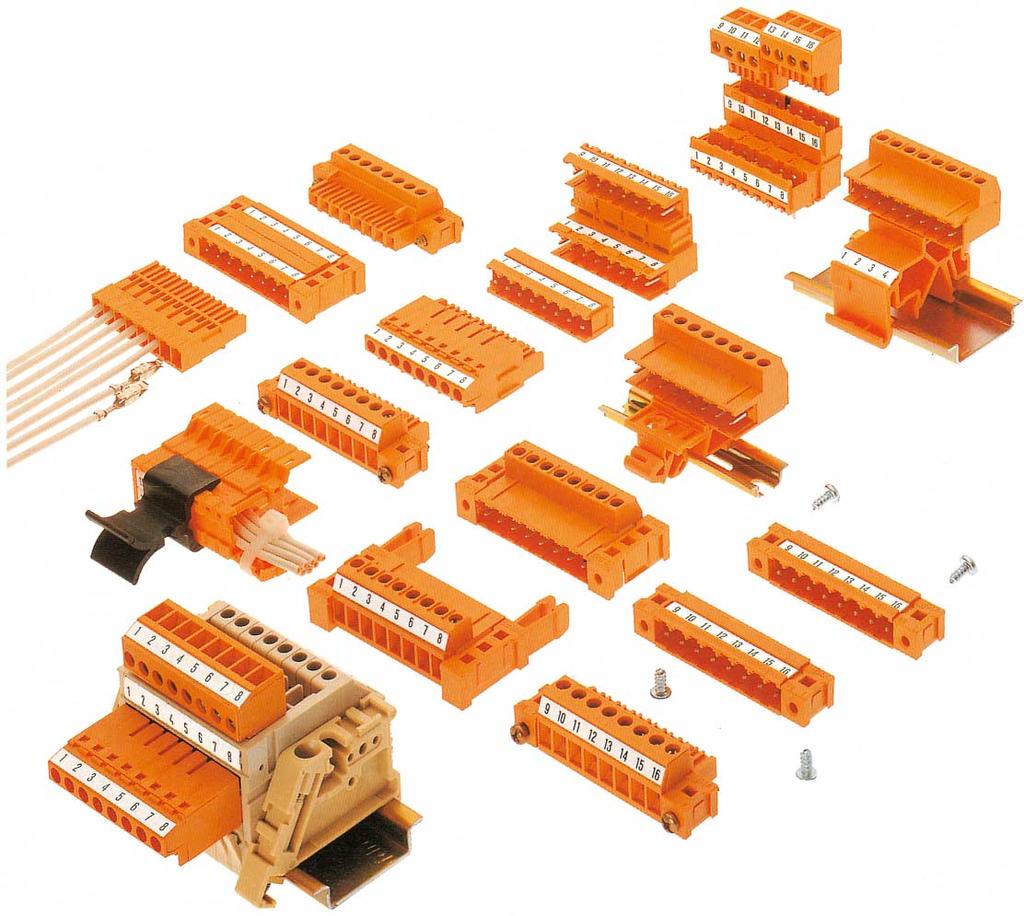
165 Connectors 158
166 Connectors SLA/BLA one-of-a-kind Only at Weidmüller: the unique connector with the secure protection against misfitment. In the SLA/BLA family of products, the pin headers and socket blocks are always paired up. That means pin headers and socket blocks with an equal number of pins. Not only this makes the Weidmüller classic unique: we assemble the product range out of glass fibre-reinforced PBT based on 5.08 mm metric pitch. Due to their amazing material properties, the pin headers and socket blocks can withstand long-term use not only at 120 C, but also at increased environmental temperatures. Even the most demanding customers can find a solution with this classic, whereas other connectors would give up. Three connection technologies are available: clamping yoke, TOP, and crimp connectors. All pin headers and socket blocks in the SLA/BLA range can be freely combined. For example, for the self wiring of initiators and actuators, interface elements and power supplies or for use in motor regulation. Overview of features Double protection against improper fitting (only connectable in pairs, only in one direction) Protection against wiring mistakes Extended use at high temperatures Voltages up to 250 V, currents up to 14 A, conductor cross-section up to 2.5 mm Glass fibre-reinforced thermoplastic polyester (PBT) as insulation material: flame resistant according to UL 94 V-0 Large selection of accessories Connectors 159
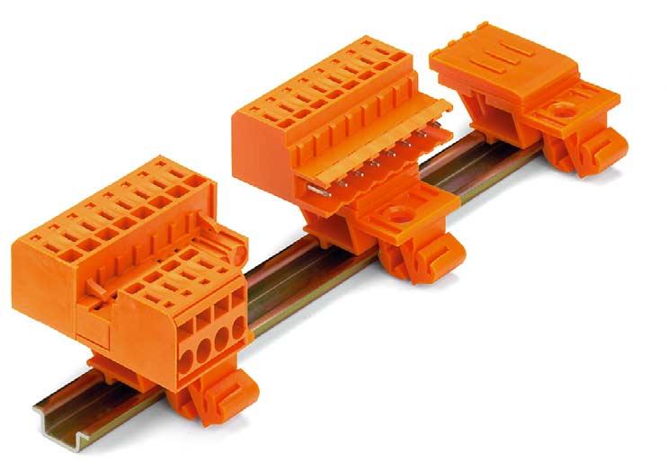
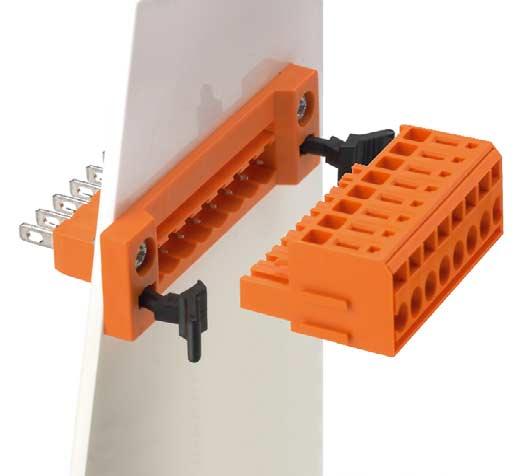
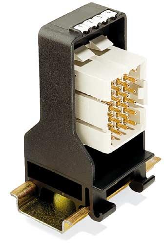
167 Other applications 160
NexT Range Large sheet steel enclosures
 Large sheet steel enclosures 8 Large sheet steel enclosures The NexT Range is the optimum choice for particularly harsh environments. The stainless steel design of the NexT Range can face up to the toughest
also in ATEX Data Sheet Enclosures Klippon POK Glass Fibre reinforced Polyester Enclosures
 Data Sheet Enclosures Klippon POK Glass Fibre reinforced Polyester Enclosures also in ATEX Weidmüller s established range of Klippon POK GRP (Glass Fibre reinforced Polyester) enclosures has been updated
Polyester enclosures CP series
 Polyester enclosures CP series BERNSTEIN polyester enclosures from the CP and CPS series are made of high-quality glass-fibre reinforced polyester. The reduced surface resistance (RO
Rittal CM Compact System Enclosures
 Rittal CM Compact System Enclosures Compact class = Top class: Infinite possibilities R Compact enclosure on the outside, Top enclosure on the inside! Index Convincing details... 3 5 Compact system enclosures
NXT Series Enclosures
 AEx Class I, Zone 1, AEx e IIC, T6 Features/Applications: The NXT series of enclosures available in two types of material finish have been designed to accommodate rail mounted terminals or other electrical
Data sheet... Klippon Klippon POK 10 Ex
 POK 10 Ex Polyester housings The glass fibre-reinforced polyester housings of the POK series represent a highquality, inexpensive solution for electric connections. These enclosures are ideal wherever
New products Ex Equipment 2015
 New products Ex Equipment 2015 ROSE Systemtechnik GmbH ROSE Systemtechnik GmbH was founded in Porta Westfalica, Germany, in 199 and is today one of the world s leading and innovative providers of industrial
Polycarbonate and ABS enclosures with quick release lid screws CT series
 Polycarbonate and s with quick release lid screws CT series The CT series of BERNSTEIN plastic enclosures are made from high-quality Polycarbonate or ABS. They are especially suitable for encapsulating
CONTENTS INTRODUCTION. Company Profile QUALITY CERTIFICATE EN ISO 9001: NEXT - Steel Enclosure Range. Product specification.
 CONTENTS INTRODUCTION Company Profile QUALITY CERTIFICATE EN ISO 9001: 2000. NEXT - Steel Enclosure Range Product specification. Product technical parameters. General arrangement drawing. Ex-Cell - Steel
EExe and EExi terminal boxes in polyester and aluminium for Ex areas
 EExe and EExi terminal boxes in polyester and aluminium for Ex areas All BERNSTEIN polyester and aluminium enclosures are available in EExe and EExi versions T II 2 G EEx e II T6 or EEx e ia IIC T6 or
ROSE Systemtechnik GmbH
 PRODUCT OVERVIEW 1 ROSE Systemtechnik GmbH The company was founded in 1969 and specializes in the development and production of high quality industrial enclosures, which are used in a variety of environmental
METTEC DESK CASES DESK CASES
 METTEC DESK CASES DESK CASES Subject to technical modification without notice. Typographical and other errors do not justify any claim for damages. Stand: 11/98 e Copyright 1998 OKW Gehäusesysteme KG Germany
Product Datasheet. Cable TV Junction Box (Page 4)
") JUNCTION BOX Product Datasheet Junction Box Bolted Type (Page 2) Cable TV Box (Page ) Cable TV Junction Box (Page 4) Telephone Box (Page 5) Telephone Junction Box (Page 6) GRP Junction Box Enclosures are
JUNCTION BOX Product Datasheet Junction Box Bolted Type (Page 2) Cable TV Box (Page ) Cable TV Junction Box (Page 4) Telephone Box (Page 5) Telephone Junction Box (Page 6) GRP Junction Box Enclosures are
Knürr Smaract. Knürr Smaract. CompactRack
 CompactRack Features Ample space for components and cabling provided in an efficient, compact design. The innovative frame concept with triangular extrusions ensures low weight while maintaining high stability.
Industrial Enclosures
 Industrial Enclosures Small enclosures from page 08 Polycarbonate enclosures PK... 0 Cast aluminium enclosures GA... 4 Terminal boxes KL... 6 E-ox E... 9 us enclosures G... 0 RiLAN Industrial IN... 4 Compact
Technical data. Material e-reinforced polyester in grey or black. Seal Neoprene (CR) round cord (siliconized)
 round cord (siliconized)") BERNSTEIN Series CP and CPS polyester enclosures are produced from highgrade e-reinforced polyester. Thanks to their reduced surface resistance (Ro < 109 Ohm), the black polyester enclosures meet the requirements
BERNSTEIN Series CP and CPS polyester enclosures are produced from highgrade e-reinforced polyester. Thanks to their reduced surface resistance (Ro < 109 Ohm), the black polyester enclosures meet the requirements
Product Datasheet. 2. GRP large rain canopy. 3. GRP door. 4. G.I Mounting plate. 5. G.I Gland plate. 6. EPDM rubber gasket
 POLYESTER ENCLOSURE SINGLE DOOR Product Datasheet GRP Single Door Enclosures are used for outdoor application with weatherproof and antistatic properties, finding their major application in the protection
Junction Boxes & Enclosures JBES and ECES Series: 316L Stainless Steel Enclosures Increased Safety
 JBES Series Medium Voltage 11 kv ECES Series Compliance Data: ATEX - IEC: ATEX IEC CE Ex e II Ex ia IIC; Ex ib IIC T6 to T4 Ex td A21 T80 C to T130 C Ex de IIC; Ex demb IIC Operating Temperatures: -50
Product Data For FARNELL
 ae Product Data For FARNELL ae Uniset is / Varioset is ae EL ELECTRONIC KOMBI SYSTEM WALL MOUNTING Pole clamp For reliable, convenient fastening to round or square poles. For pole diameter/size:
T ~ \ u " NEW. Data sheet Enclosures. Klippon STB Stainless Steel Enclosures
 ata sheet nclosures Klippon S Stainless Steel nclosures NW ~ \ u " For many decades the name Klippon has been synonymous for competence and quality in our proven supply of enclosures and customer solutions
Number of PG holes. 1 x PG 9 (Ø 15.5) 12 x PG 13.5 (Ø 21) 1 x PG 9 (Ø 15.5) /300/400/ Rittal Catalogue 32/Industrial Enclosures
 12 x PG 13.5 (Ø 21) 1 x PG 9 (Ø 15.5) /300/400/ Rittal Catalogue 32/Industrial Enclosures") us enclosures G. us enclosures Enclosure:.38 Door:.5 IP 65 to EN 60 59/09.00, complies with NEMA. Door with l/h hinge, cam lock with double-bit insert, () support rail(s) S 35/7.5 (for G 586.). Drilled
us enclosures G. us enclosures Enclosure:.38 Door:.5 IP 65 to EN 60 59/09.00, complies with NEMA. Door with l/h hinge, cam lock with double-bit insert, () support rail(s) S 35/7.5 (for G 586.). Drilled
Glass Reinforced Polyester Enclosures
 42 The GRP range comprises 16 sizes of enclosure manufactured in glass reinforced polyester (GRP). This material is highly resistant to contamination from oils, fats, aliphatic and aromatic carbohydrates,
Junction box for EKL light
 M EKL light Junction box Junction box for EKL light Features Chemical-resistant Temperature-resistant Flame-retardant Absolutely corrosion-proof Seawater-proof Description Polyester enclosures have proven
IP65/IP66 ABS/Polycarbonate Screw Lid Boxes
 IP65/IP66 ABS/Polycarbonate Screw Lid Boxes p Versatile, lightweight & durable p Choice of materials: polycarbonate for rugged applications or ABS as an economic alternative p IP protection for outdoor
I Ex-e/Ex-i terminal box I
 ID TAG label & bracket Door document holder opti. Security padlock Hasp opti. Technical data Marking accd. to 94/9/EC II G Ex e II / II D Ex td A1 IP66 Temperature class T6 up to +40 C / T5 up to +55 C
2: Ecokit Ecokit 11 Overview A 2_ Ecokit 11 Sub Rack Configuration A 2_ Width A 2_ Height / Depth A 2_6
 2: Ecokit 11 2.1 Ecokit 11 Overview 2_3 2.2 Ecokit 11 Sub Rack Configuration 2_5 2.2.1 Width 2_5 2.2.2 Height / Depth 2_6 2.2.3 Handles 2_6 2.2.4 Line Drawing 2_7 2.3 daptation Kits 2_8 2.3.1 daptation
IP65 enclosures orion plus
 IP65 enclosures orion plus One system for indoor and outdoor application Sheet steel or glass reinforced polyester - the orion plus enclosures are suited for harshest conditions and can be applied for
Rolec aludisc. The round enclosure. Roundly complete.
 Our passion is enclosures. Project 20. An entirely new concept. Rolec aludisc. The round enclosure. Roundly complete. There are industries in which everything is round. Tanks. Pipes. lamps. Displays. Instruments.
The range is fully compatible with the PS system accessories.
 The ES 5000 exclusive enclosure the compact enclosure system with multiple benefits Compact for electronics, ideal for machine control, generously proportioned for climate control, flexible and cost-effective
Outdoor system solutions
 Outdoor system solutions 2 The whole is more than the sum of its parts The same is true of Rittal The System. With this in mind, we have bundled our innovative enclosure, power distribution, climate control
Empty enclosures IEC 62208
 374 www.hensel-electric.de/en in accordance with for customized solutions and individual applications for example for low-voltage switchgear and controlgear assemblies i n accordance with the IEC 61439-series
19" chassis F. Downloads and further important information can be found on the Internet under Overview Cabinets...
 Overview... 0 Cabinets... 1 19" chassis Wall mounted cases... 2 Accessories for cabinets and wall mounted cases... 3 Climate control... 4 Desk-top cases... 5 02192001 Subracks/ 19" chassis... 6 ront panels,
Rittal console systems...
 Rittal console systems...... multi-variable Universal console Optionally with short or tall door. Short door offers free field for mounting desk section (see photograph) or keyboard drawer. High level
Part-No. Article / Version Supply A Tilt foot bar of ABS, off-white RAL 9002 A
 *Mounting angle ( ) on the adapter serves as a support to locate the case in the right position. After attachment of the adapter, the mounting angles can be easily removed. Tilt foot bar, Case feet TILT
The Ex-Cell-I series is made for instrumentation with easy access central locking system and hinged cover.
 E X - T E R M I N A L E N C L O S U R E S Stainless Steel Version for Zone and Zone 2 The enclosure range is an ATEX certified enclosure / termination solution for category 2 (Zone) application with an
Product Data For FARNELL
 ae Product Data For FARNELL ae Uniset is / Varioset is ae EL ELECTRONIC KOMBI SYSTEM WALL MOUNTING Pole clamp For reliable, convenient fastening to round or square poles. For pole diameter/size:
SITRANS P measuring instruments for pressure
 Overview Siemens AG 009 Supplementary electronics for 4-wire connection Design Dimensions (W x H x D) in mm (inch) Electrical connection 80 x 10 x 60 (3.15 x 4.7 x.36) Screw terminals (Pg 13.5 cable inlet)
Prisma Plus G enclosures IP30, IP31, IP43 enclosures
 Prisma Plus G IP30, IP31, IP43 Prisma Plus G IP30, IP31, IP43 Presentation For safe and upgradeable electrical switchboards > Safety of people and property > Continuity of service > Optimization and upgradeability
General characteristics
 Multipole Industrial Connectors General characteristics The multipole connectors for industrial purposes are used in electric and electronic machinery, robots, electric panels, control equipments and wherever
Rittal Small Enclosures
 Rittal Small Enclosures Fast and perfect, with an exceptionally diverse range of system accessories R The original is still the best! Packaging technology for the future Whether you require enclosures
ENCLOSURE CATALOGUE Ensto Cubo
 ENCLOSURE CATALOGUE Ensto Cubo www.ensto.com 2 Ensto at your service We are a specialist in the field of enclosures and customer-specific enclosure solutions. Our standard product range includes thermoplastic,
Polyester-Enclosures MBP
 24 MULTI-BOX Enclosure solutions Polyester-Enclosures MBP Protection class IP 66 MBP-Enclosures correspond with the high requirements of the mechanical engineering, shipbuilding, galvanic and petrochemical
Catalog / 2016 North American Edition
 Catalog 34 2015 / 2016 North American Edition without knockouts without knockouts without knockouts without knockouts PK Polycarbonate Housing Height inches (mm) Packs of 4.3 (110) 4.3 (110) 4.3 (110)
Euromas-Polyester, an enclosure available
 Euromas-Polyester 8 Euromas-Polyester, an enclosure available in sizes made of 0% glassbead-reinforced polyester, has been designed to satisfy the highest standards. It makes it possible for the user to
2: Stylebox Stylebox 15 Overview B 2_ Complete Stylebox 15 Kits B 2_ Stylebox 15 Standard Kit B 2_8
 2.1 Stylebox 15 Overview 2_3 2.1.1 Complete Stylebox 15 Kits 2_7 2.1.2 Stylebox 15 Standard Kit 2_8 2.2 Stylebox 15 Smart 2_10 2.2.1 Width 2_11 2.2.2 Height ezel 2_11 2.2.3 Depth 2_11 2.2.4 Top Cover Panel
OUR VISION STAINLESS STEEL MILD STEEL MODULAR FLOOR STANDING NON METALLIC P F BLACKBURN SOUTH VIC 3130
 Excalibur REAZ AUSTRALIA Enclosures PTY LTD 59 P.O. Northville BOX 2340 Drive Barnsley NSW 2278 BLACKBURN SOUTH VIC 3130 T - 03 9878 4141 sales@reaz.com.au EX-EC/S General Purpose Wall Mount Enclosures
ACCESSORIES FOR SZE2 CABINETS
 ZPAS 143 DOORS Doors Intended for use instead of front solid door or rear panel. Maximum door opening angle: 120 Sheet steel textured powder paint, light grey (RAL 7035), stiffened profiles, brown smoked
stainless steel Cover hinge The cover hinge is simply screwed to the box protection channel and to the edge fold. Model No. KL
 aus HB, S. 46 The Rittal range of terminal boxes offers 44 practical designs, developed and improved in constant dialogue with users. Whether with or without gland plates, in stainless steel, EMC version
YOUR WISH IS OUR COMMAND. Junction boxes. Catalogue-Junction boxes
 YOUR WISH IS OUR COMMAND Junction boxes Catalogue-Junction boxes 04 Index Index Hard rubber junction boxes Technical notes Type 1010 Type 1212 Type 1616 Type 1812 Type 2516 Type 1010- Type 2516 Pages 4-8
Emergency Light Fitting for Fluorescent Lamps Series ECOLUX 6608 Economy
 www.stahl.de > For fluorescent lamps 2 x 18 W and 2 x 36 W > Electronic ballast with integrated emergency light electronics > Battery is integrated in the lamp enclosure > For emergency light mode 1.5
BOXES WALL-MOUNTING BOXES AND TERMINAL BOXES
 BOXES WALL-MOUNTING BOXES AND TERMINAL BOXES ST WALL-MOUNTING BOXES WITH BLANK DOOR STP WALL-MOUNTING BOXES WITH PLEXI DOOR ST/STP COMPLEMENTARY ACCESSORIES SDV TERMINAL BOXES WITH SCREWED COVER SDF TERMINAL
13.1. Range of Enclosures. KRONECTION Box A 2 for up to 2 pairs. Expert Knowledge. Short survey of the KRONECTION Box A 2 for up to 2 pairs
 KRONECTION Box A 2 for up to 2 pairs Short survey of the KRONECTION Box A 2 for up to 2 pairs The KRONECTION Box A 2, which is equipped with connection contacts on the right and left, serves as a line
4.6. Ex-Floodlights for high-pressure discharge lamps, series FZD 04 / FZD EN. (Zone 1, 2, 21, 22)
") .6 Ex-Floodlights for high-pressure discharge lamps, series FZD 0 / FZD EN (Zone 1, 2, 21, 22) The maintenance- and installation-friendly FZD 0 floodlights for harsh operating conditions Due to the spatial
.6 Ex-Floodlights for high-pressure discharge lamps, series FZD 0 / FZD EN (Zone 1, 2, 21, 22) The maintenance- and installation-friendly FZD 0 floodlights for harsh operating conditions Due to the spatial
Pixus Technologies Catalog
 The Power of Embedded Ingenuity Pixus Technologies Catalog Kaparel, Ripac, & Vario Brand Products www.pixustechnologies.com sales@pixustechnologies.com US: 916.524.8242 CN: 519.885.5775 Product Diversity
Light Fitting for Fluorescent Lamps Series ECOLUX 6600
 > 1- or 2-lamp version: 18 W 36 W 58 W > Enclosure in polyester resin, glass fibre reinforced and cover in polycarbonate, impact-resistant > Quick fasteners www.stahl.de 10032E00 The light fittings series
SINGLE DOOR BOXES. PAINT FINISH ETA standard epoxy polyester powder coating. Enclosure and door: colour RAL 7035 textured finish.
 ST SINGLE DOOR BOXES Enclosure and door manufactured from 1.5 mm thick sheet steel. Mounting plate manufactured from 2.5 mm thick sendzimir sheet steel. Enclosure and door: colour RAL 7035 textured finish.
E3 VISE ACTION Compression Latch
 38 E3 VISE ACTION Compression Latch Overview First 90 0 turn: rotates behind frame The door is now latched against opening Then as you complete the half-turn motion, the shaft and cam compress to pull
4.7. Ex-Floodlights for high-pressure discharge lamps, series FZD 04 (Zone 1, 2, 21, 22)
") .7 Ex-Floodlights for high-pressure discharge lamps, series FZD 0 (Zone 1, 2, 21, 22) The maintenance- and installation-friendly FZD 0 floodlights for harsh operating conditions Due to the spatial separation
.7 Ex-Floodlights for high-pressure discharge lamps, series FZD 0 (Zone 1, 2, 21, 22) The maintenance- and installation-friendly FZD 0 floodlights for harsh operating conditions Due to the spatial separation
VALVE CONTROLLERS Controllers for Dust Extr 2010 / 2011 action Technology
 VALVE CONTROLLERS Controllers for Dust Extraction 2010 Technology / 2011 Valve controllers for all cases HESCH has the skills and technology to tackle any control task for dedusting of filter and dust
Conveyors 12. slide strips roller Conveyors roller elements Conveyor rollers Chain Transfer
 Conveyors slide strips roller Conveyors roller elements Conveyor rollers Chain Transfer Application example conveyors Transport solutions and goods provision 1 2 3 4 5 6 7 8 362 9 1 slide strips Low-wear
2.1 Accessories System for Enclosures CRN-CRS
 nclosures Wall Mounted 2.1 Accessories ystem for nclosures CRN-CR Mounting plates A complete range of mounting plates comprising 4 versions able to provide all the mountings needed for this installation
RockStar HighPower. Contents. RockStar HighPower Introduction C.2 C.1
 ontents Introduction.2 HighPower 250 A.4 4000 V 250 A 1 4 poles HighPower 550 A.10 4000 V 550 A 1 3 poles.1 Introduction Uncompromising power in clever and safe packaging. The modular high-current connector
Safety enclosures Normal atmospheres steel enclosure from 50 to 1600 A
 Integrated products & solutions The solution for > Iron and steel industry > Cement plants > Paper mills > Sawmills > Hydraulic power packs > Automotive > Mining coff_436_a coff_434_a Strong points Function
Small cases... the perfect shell for valuable electronics
 Small cases... the perfect shell for valuable electronics Small cases page 178 mini page 181 page 183 all standard size cards (100, 120, 160, 190 to 233,35 ) can be installed in one case favourable EMC
Hygienic Design. 1.5 Hygienic Design
 Hygienic Design.5 Hygienic Design For the design of production plant in open processes in the food and consumables industry where ease of cleaning is crucial. When it comes to the exacting demands of food
Pixus Technologies Catalog
 The Power of Embedded Ingenuity Pixus Technologies Catalog Kaparel, Ripac, & Vario Brand Products www.pixustechnologies.com sales@pixustechnologies.com US: 916.524.8242 CAN: 519.885.5775 Individual Subrack
Bocube. Colour: Graphite grey, similar to RAL 7024; light grey, similar to RAL 7035; special colours on request
 Bocube Detailed product information can be found on www.bopla.de - Patented, innovative, hinged quick-release catch technology without screws: open with a screwdriver, close by hand - 22 sizes, 132 standard
Rolec aluplus. The PlUS in technology and design.
 Our passion is enclosures. The evolution in enclosure technology. Rolec aluplus. The PlUS in technology and design. 2 Rolec milestones in enclosure development. Our passion is enclosures. aluplus The evolution:
2 Rittal climate control/wall-mounted cooling units Blue e+
 World s first The principle 2 Rittal climate control/wall-mounted cooling units Blue e+ The whole is more than the sum of its parts The same is true of Rittal The System. With this in mind, we have bundled
Emergency Light Fittings for Fluorescent Lamps Series ECOLUX 6608
 > For fluorescent lamps 2 x 18 W and 2 x 36 W > For emergency light operation periods of 1.5 or 3 hrs > During emergency time: If emergency lamp broken changing to the other lamp > Battery case which can
IN STAINLESS STEEL: Compact enclosures Enclosures and support arm systems for the human/machine interface Large enclosures
 IN STAINLESS STEEL: Compact enclosures Enclosures and support arm systems for the human/machine interface Large enclosures R RITTAL SYSTEM PARTNERS Perfect holistic solutions Be it automation, communications
Innovations. Supplement to Eldon Product Catalogue
 Innovations Supplement to Eldon Product Catalogue Table of contents Quick fixation baying brackets... 4 Mounting plate brackets... 6 Profile system... 8 Side panel improvement... 10 Easy fixation with
Light Fitting for Fluorescent Lamps Series ECOLUX 6600
 > 1- or 2-lamp version: 18 W 36 W 58 W > Enclosure in polyester resin, glass fibre reinforced and cover in polycarbonate, impact-resistant > Quick fasteners www.stahl.de 10032E00 The light fittings series
Operating Instructions
 Operating Instructions Terminal Box > 8150/1 > 8150/2 Contents 1 Contents 1 Contents...2 2 General Information...2 2.1 Manufacturer...2 2.2 Operating Instructions Information...2 3 Intended Use...2 4 Safety
4 Remote I/O. Enclosures for Fieldstations Series 8126 (Customer-Specific)
") 4 Remote I/O Series 86 078E00 Series 86 enclosures of glass-fibre reinforced polyester resin or of high grade steel are used in larger control stations and control station combinations. Special sizes are
4 Remote I/O Series 86 078E00 Series 86 enclosures of glass-fibre reinforced polyester resin or of high grade steel are used in larger control stations and control station combinations. Special sizes are
Stirrup-shaped handles, machine handles, apparatus handles
 Stirrup-shaped handles, machine handles, apparatus handles 231 K0186 Stirrup-shaped handles GJS 400 Deburred and tumble cleaned; black plastic coated; machined contact faces. KIPP Stirrup-shaped handles
Linear Luminaire for Fluorescent Lamps Series ECOLUX 6600
 > 2-lamp version: 18 W 36 W 58 W > Enclosure in polyester resin, glass fibre reinforced and cover in polycarbonate, impact-resistant > Quick fasteners www.stahl.de 10032E00 The light fittings series 6600
EB SERIES INSTRUMENT ENCLOSURES
 EB SERIES INSTRUMENT ENCLOSURES EB Series Instrument Enclosures 1 5 2 7 4 6 Multiple-fold 1 gutter type edge provides extra stability and protects against dirt and water when enclosure is opened. Grounding
Easy and safe installation
 ATX LUMINAIRES 7 Easy and safe installation 1 2 3 Safety Plus : 1- Mounting can be completed with one hand 2- One handed opening using standard tool 3- Reflector swivels easy access 4- Terminal shield
Consumer units. Index. Pages. Consumer units UK500 series 1-3 Product features 1-12 Ordering information 1-18 Technical information
 Consumer units Index Pages 01 Consumer units UK500 series 1-3 Product features 1-12 Ordering information 1-18 Technical information Consumer units A300 series 1-21 Product features 1-22 Ordering information
HINGES Weld-on Hinges Steel. Weld-on Hinges Steel. MATERIAL Steel. FINISH Raw. FEATURES Brass Washer Steel Pin Grease Nipple
 47 48 Weld-on Hinges 7004.00 Raw Brass Washer Pin Grease Nipple Weld-on Hinges 7010.00 Raw Brass Washer Pin 49 Weld-on Hinges 7005.00.080, 7005.00.100 Raw Brass Washer Brass Pin Grease Nipple 7005.00.080
Junction boxes. X series
 Junction boxes X series X-TREME The new X series Extremely robust With the X series, OBO Bettermann can offer a range of junction boxes and empty housings that can withstand even the toughest mechanical
USA Canada On the Internet: Toll Free wieland Product Range Electrical Connections
 0.2 F 01/02 270 Excerpt from our master catalogue wiecon PCB terminals In Ageneral, all Wieland components which are obliged to have the identification are provided with the A mark Pluggable PCB terminals
IECEx Certificate of Conformity
 Certificate of Conformity: IECEx BAS 07.0033X http://iecex.iec.ch/iecex/iecexweb.nsf/fc034777969a786bc1256d42005bd791/9e9052... Page 1 of 4 18/06/2008 IECEx Certificate of Conformity INTERNATIONAL ELECTROTECHNICAL
Technical Data Sheet :
 Technical Data Sheet : Die-cast Aluminium Enclosure Material: AI Si 12, as per DIN EN 1706 Components: Fastening threads M4 / M6 in the enclosure bottom. Ingress protection: IP66 / IP67 / IP68 as per IEC
Locking System. White Paper
 Locking System White Paper Contents Introduction...4 Easy Integration...4 Benefits...4 Floor standing Mild steel...5 Floor standing Stainless steel... 10 Floor standing Aluminum... 15 Wall mounted Mild
Klippon TBi FS Fixing Screw
 Klippon Ti S - ixing Screw Klippon Ti S ixing Screw Stainless steel enclosures for use within harsh industrial environments ven under moderate environmental conditions, there is an increasing need for
EPIC. Connector Accessories CONNECTOR ACCESSORIES. Glands, Seal Rings & Adapters Glands 412 EPIC SM & SP Glands, EPIC CM-M Glands
 CONNECTOR ACCESSORIES Glands, Seal Rings & Adapters Glands 412 EPIC SM & SP Glands, EPIC CM-M Glands D Series Pressure Screws 413 U Series Washers 413 Sealing Rings 413 Neoprene & Viton Concentric Sealing
Overview of junction boxes
 Overview of junction boxes ariety Staying young A series Classic and still youthful: The wellknown junction boxes of the A series have had a makeover. Halogen-free thermoplastic is just as much of a hallmark
Eldon MultiFlex platform ACCESSORIES FULLY COMPATIBLE BETWEEN RANGES. MultiCOM Aluminium. MultiFlex
 Floor Standing NEWS The new Eldon MultiFlex platform - Easy to work with! In a major development, Eldon has standardized all of its floor standing product lines around its respected and best-selling MultiFlex
Fiberglass Watertight Modular Flange Product Drawings Last Updated 1/6/2006
 ROSE+BOPLA ENCLOSURES A PHOENIX MECANO COMPANY Fiberglass Watertight Modular Flange Product Drawings Last Updated 1/6/2006 Dimensional Drawings All sizes are available with an optional clear viewing lid.
10 Load and Motor Switchgear
 10 Load and Motor gear Safety es 01941E00 Safety switches ensure the obligatory isolation of electrical power under condition of equipment cleaning, maintenance and repair. Other methods of isolation,
1.6 Accessories include tool-free snap-in technology options for air flow, cable management, shelves, power distribution units, etc.
 Rittal TS IT Rack Guide Specifications TS IT network server enclosure 1.0 General Description 1.1 Modular Free Standing Equipment Cabinet 1.2 Various combinations of dimensions: 1.2.1 Height: 48 /1200mm,
A good connection. International approvals.
 E X - P L U G S A N D R E C E P T A C L E S 0 A to 25 A plugs and receptacles plastic version for zone, 2, 2 and 22 A good connection Providing electrical energy there, where it is most needed even in
Operating Instructions (Translation)
") Product Description Definition The ANTARES RCU consists of the ANTARES Head Module and the ANTARES Connection Module. The ANTARES Head Module contains a CPU, communication interface and power pack. In
Product Description Definition The ANTARES RCU consists of the ANTARES Head Module and the ANTARES Connection Module. The ANTARES Head Module contains a CPU, communication interface and power pack. In
Weld-on Hinges Weld-on Hinges
 54 53 Weld-on Hinges 7004.00 Satin Brass Washer Pin Grease Nipple Weld-on Hinges 7004.90 Aluminium Satin Stainless Washer Stainless Pin Grease Nipple 55 Weld-on Hinges 7005.00.080, 7005.00.100 Satin Brass
W Series Cast Junction Box Options Boxes Available for Raintight, Watertight, or Submersible Applications
 W Series Cast Junction Box Options Boxes Available for Raintight, Watertight, or Submersible Applications This table shows the optional items available on the different types of enclosures shown in this
Always a little more flexible: häwa enclosures. Industrie 4.0
 Always a little more flexible: häwa enclosures häwa Industrie 4.0 ready Enclosures Is there actually an efficient solution in the häwa range of enclosures that complies with our requirements? The best
Accessories Cable glands
 Accessories Cable glands 235 Technical data Cable glands Brass hexagon cable gland Brass sealing cable gland Material: Brass, nickel-plated Gasket: Soft rubber Protection type IP 54 Additional information:
MODE - Multiple Occupancy Distribution Equipment Selection guide for low voltage indoor distribution up to 500A
 MODE - Multiple Occupancy Distribution Equipment Selection guide for low voltage indoor distribution up to 500A MODE - Multiple Occupancy Distribution Equipment Contents 4 MODE range: introduction 5 MODE