9728E APPLICATION CONSIDERATIONS
|
|
|
- Scot Little
- 6 years ago
- Views:
Transcription

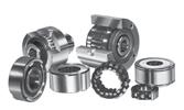

1 Bearings - Metric
2
3 BEARING TYPES DEEP GROOVE BALL BEARINGS SELF-ALIGNING BALL BEARINGS ANGULAR CONTACT BALL BEARINGS CYLINDRICAL ROLLER BEARINGS SPHERICAL ROLLER BEARING ADAPTER SLEEVES TAPERED ROLLER BEARING THRUST BALL BEARING SPHERICAL ROLLER THRUST BEARINGS 1
4 CONTENTS PART 1 Page 1) Bearing types and application 4 - Selection 12 - Life & load ratings 16 - Speed 42 - Bearing materials 44 - Suffixes & prefixes 46 2) Lubrication 48 - Handling of bearings 53 3) Fits and clearances 57 - Single row deep groove ball bearings 60 - Single row angular contact bearings 62 - Double row self-aligning ball bearings 63 - Single & double row cylindrical roller bearings 64 - Double row spherical roller bearings 66 - Double & four row tapered roller bearings 69 4) Shaft & housing tolerances 70 - ISO IT tolerance range 79 - Tolerance symbols 80 - Radial bearings 82 - Tapered roller bearings 86 - Double row cylindrical roller bearings 92 - Thrust bearings 94 - Limit dimensions of chamfer 98 - Snap ring and groove tolerances Abutment recommendations 102 2
5 PART 2 - Single row deep groove bearings Self aligning ball bearings Single & double row angular contact bearings Single & double & four row cylindrical roller bearings Spherical roller bearings Adapter sleeves Tapered roller bearings Thrust ball bearings Spherical roller & tapered roller thrust bearings 289 3
6 BEARING CHARACTERISTICS Characteristics of bearing types and application Deep groove ball bearings Deep groove ball bearings are non-separable, comparatively rigid radial bearings, their balls are guided in deep radial running grooves. They are characterized by a high radial and axial load carrying capacity and can operate at very high speed. Combined loads are accommodated to an optimum degree, in fact at higher speeds they are often better suited to transmit thrust loads than the ball thrust bearing. For these reasons and also economical price, it is the most widely used bearing. Deep grove ball bearings are also available with one or two non-rubbing metal shields (Z, ZZ) or rubbing seals (RS, 2RS) made from synthetic rubber. Bearings with two shields or two seals are pre-lubricated with the correct quantity of grease of a lithium base which permits operating temperatures of 30 C C. Deep groove ball bearings with snap ring groove (N) and snap ring in the outer ring enables a simple and space-saving axial location in the housing. Angular misalignment The following is an approximate guide to the misalignment that can be accommodated in the use of a single row ball bearing: radians A greater degree of misalignment can sometimes be accommodated if pure radial load is applied, particularly if the misalignment results from occasional peak load, and if the bearing had sufficient radial internal clearance after mounting to avoid excessive stresses. 4
7 Angular contact ball bearing There are single-row and double-row angular contact bearings and also duplex ( four point contact bearing). Single-row angular contact ball bearings are nonseparable and the standard types feature a contact angle of 40. They are suitable for the accommodation of combined (radial and axial) loads. Axial loads optimum load may be transmitted in the direction of the closed faced or high shoulder only. Optimum load transmission starts whit F a F r. Radial forces induce internal axial forces which are absorbed by the opposed bearing. Such bearings should therefore be mounted in pairs of should be adjusted against another bearing. In the case of length variations of the shaft caused by changes in temperature, which, in turn, affect the internal clearance, the distance between the bearings should be kept small. The maximum permissible speed is somewhat lower than that of deep groove ball bearings. A slight angular deflection is still possible whit the single bearing; if bearings are mounted in pairs, however, rigidity greatly increases together with the ability to prevent misalignment. Single-row angular contact bearings can also be supplied with side faces ground for mounting side-by suffix G being used in the bearing designation, ie 7250 BG. They can be mounted in any of three combinations depending on the loading characteristics: A back-to-back arrangement (closed face together, load line of the bearings diverging towards the shaft axis) is used where rigidity and an ability to absorb fitting moment is required. Back-to-Back DB Face to Face DF A face-to-face arrangement (open faces together, load line of the bearings converging on shaft axis) is used where axial loads acting in both directions are to be catered for by one bearing in one direction. Rigidity is not as good as the back-to-back arrangement and there is less ability to absorb fitting moments. 5
8 A tandem arrangement (open face-to-closed-face load lines being parallel to each other) is used for thrust loads equally distributed over all bearings, absorbed in one direction only. Adjustment against another bearing which accommodates the opposed thrust load is necessary. Tandem DT Double row angular contact bearings The inner and outer ring of these bearings each have a double raceway and the two rows of balls are so related that the contact angles are similar to that for a back-to-back arrangement. Thrust loads can be accommodated in either directions as well as fitting moments. Four point (duplex) Double row The four-point contact bearings or duplex bearings are in principle angular contact bearings that accommodate axial loading one direction or the other. They usually have mare axial movement than a pair of angular contact bearings correctly adjusted endwise; they are also able to carry combined radial and axial loading, providing the axial load at all times exceeds the radial load. Duplex bearings should not run unloaded, particularly at high speeds, for in this condition the balls contact the raceways at three or four points instead of two points necessary to correct running. Three or four point contact results in over-heating due to the balls skidding. When duplex bearings are required to carry axial loads only, then the outer rings must have radial clearance in the housing. 6
9 Angular misalignment The following is an approximate guide to the misalignment that can be prevalent when fitting angular contact bearings radians Greater misalignment, particularly under pure axial load can become critical. Double row self-aligning ball bearings This design of bearing utilizes two rows of balls with the inner ring having two deep groove raceways while the outer ring has a single continuous spherical raceway. This permits the inner and outer ring to be misaligned relative to each other through a comparatively large angle without imposing moment loads upon the balls. This bearing is frequently used when the inner ring is to be mounted upon an adapter sleeve or when conditions in the machine make it difficult to assure accurate alignment of the inner and outer rings. Due to the small contact angle, the thrust capacity of these bearings is limited. Angular misalignment Cylindrical Bore Tapered Bore 1:12 The following is an approximate guide to the misalignment that can be accommodated in a double row self-aligning ball bearing radians between 2.5 and 3 degrees depending on which series is used. Bearing series Permissible Angular Misalignment Degrees
10 Cylindrical roller bearings The rollers of these bearings are essentially cylindrical in shape providing modified line contact with the cylindrical inner and outer ring raceways. The rollers are accurately guided by ground ribs on either the inner ring or the outer ring, thus making these bearings suitable for heavy radial loads and high speed operation. For best results, these bearings should be accurately aligned. The cylindrical shape of the rollers allows the inner ring to have considerable axial movement relative to the outer ring ( except the NH type). This feature is valuable in accommodating thermal expansion in applications where both the inner ring and outer ring must be press-fitted. Also, since the inner and outer rings are separable from each other, the assembly of equipment is frequently facilitated. NU NJ NUP N RNU NJ+HJ Angular misalignment the following is an approximate guide to the misalignment that can be accommodated in a cylindrical roller bearing : radians Greater misalignment under heavy radial load can be critical. 8
11 Tapered roller bearings This design utilizes conical rollers and raceways arranged so that all elements of the roller and raceway cones meet at a common apex on the axis of rotation. The rollers are guided by contact between the large end of the roller and a rib on the high capacity for radial loads and single direction thrust loads. The bearings are usually mounted in pairs with axial adjustment to provide proper running clearance within the bearings. Being separable, inner and outer rings may be mounted individually. For heavy thrust loads, the type D (formerly 30300) with large contact angle is desirable. Tapered roller bearings with two and four rows of rollers are used for special applications. Angular alignment The following is an approximate guide to the misalignment that can be prevalent when fitting tapered roller bearings: 2 mins of arc This is under normal loading conditions. 9
12 Spherical roller bearings In this design, two rows of rollers operate in separate raceways ground into the inner ring with guide rib to guide the rollers. The outer ring has a single spherical raceway, thus allowing the inner ring and rollers to freely compensate for angular errors due to inaccurate machine components or due to elastic deflection of the shaft or housing under load. As a result of the line contact, a large number of rollers, and the substantial contact angle, these bearings have large radial and thrust load capacity. They are suitable for heavy shock and impact loads and thus are extensively used in steel mills, rock crushers, and heavy industrial equipment. Cylindrical tapered bore lubrication adapter withdrawal bore K 1: 1:12 groove and sleeve H sleeve AH K30: 1:30 holes W33 Angular misalignment The following is an approximate guide to the misalignment that can be accommodated in a spherical roller bearing-between 1 and 2,5 degrees depending on which series is being used: Bearing series Permissible angular misalignment degrees
13 Thrust ball bearings Thrust ball bearings are separable bearings. The single-acting thrust ball bearing consists of shaft washer, housing washer and ball set with cage, the double-acting type of a shaft washer ( centre washer), two housing washer and two ball sets with cages. Thrust ball bearings can be applied for high axial loads and low to medium speeds, they cannot, however, take radial loads. They are sensitive to angular deflection and characterized by extremely rigid guidance in axial direction. Depending on speed a minimum load is necessary to avoid sliding movements of the ball set, which are caused by centrifugal forces. To compensate for misalignments of the shaft, bearings with spherical housing washers and support washers should be used. 11
14 BEARING SELECTION The following procedure gives the steps to be followed when bearings are selected from the information contained in this catalogue. It will be found satisfactory for most applications. 1. Determine the speed of the bearing Calculate the loads on the bearings. 2. Establish if accurate alignment can be obtained between the bearing seatings. If it cannot, then bearings that accommodate misalignment should be selected. 3. If the bearings rotate under loud decide the life required, calculate the required dynamic load rating C values, and then select suitable bearings that have comparable C values. If the bearings do not rotate under load selected them by using the static load rating C Check if the bearings are suitable for the speed and decide of grease or oil is to be the lubricant. 5. Select a suitable bearing arrangement of this is not already known; make sure that the seating fits required can be used with this arrangement. 6. Finally decide if bearings to Standard or Extra Precision limits of accuracy are required. Select the most suitable range of radial clearance. Choose the abutment diameters. Choose suitable closures. Issue mounting and handling instructions for the bearings if necessary. 12
15 Selecting of bearing type Each type of bearing had different properties making it suitable for certain applications. The factors to be considered when choosing a bearing are numerous so guidance is given to the main points when selecting a bearing. It must also be remembered that special consideration must be given to aspects relating to the running and operating consideration must be given to aspects relating to the cases at least one of the principal dimensions of the bearing has been determined by the machine design or shaft size. Load and direction of load The magnitude and direction of the external loads along with built in factors of safety are two of the main points which determine the bearing size and in some instances the bearing type to be used. The important factors are the speed of rotation, temperature, the amount of precision required, mounting conditions and running noise. The following illustrations indicate the magnitude and direction of the external loads which the bearings will provide for. Radial loads For light and medium radial loads ball bearings are generally used, whereas for heavy loads and large shaft diameters roller bearings are often the only choice. Cylindrical roller bearings are available in several types. Types NU (with outer ring ribs) and N (with inner ring ribs) are only suitable for radial loads, whereas the NUP, NJ and NJ with angle ring HJ can be used to a certain extent to take combined loads. Thrust loads Thrust ball bearings are only suitable for light or medium purely axial loads. Double-acting thrust ball bearings can carry thrust loads in either direction. Spherical roller thrust bearings are used where heavy thrust loads are to be absorbed and in addition can carry a certain amount of radial load acting simultaneously. Combined loads If a radial and thrust load act on a bearing simultaneously this is termed as a Combined Load. The most important feature affecting the ability of carry axial loads is the angle of contact in relation to the shaft axis. The greater the angle, the more suitable the bearing is to accommodate axial loading. Combined loads are carried by deep groove ball bearings, self-aligning ball bearings, four point bearings, single and double row angular contact bearings, spherical roller bearings, cylindrical roller bearing of the locating types and taper roller bearings. 13
16 Limiting speed The speeds at which bearings can rotate are limited by the bearing type, the operating load and the permissible operating temperature of the lubricant. Bearings with low frictional resistance and correspondingly low internal heat generation are most suitable for high speeds with proper attention being given to the correct bearing clearance after mounting. For radial loads the bearings most suitable are deep groove ball bearings or cylindrical roller bearings for combined loads angular contact bearings should be selected. Misalignment Self aligning ball bearings, spherical roller bearings and spherical roller thrust bearings allow, at assembly, for the correction of misalignment where the shaft can be misaligned relative to the housing. Values for permissible angular misalignment are listed in the tables which precede the bearing sizes of those particular types. Low noise level Even thought the running noise of rolling bearings is so lox that it is lost in the background noise of other moving parts. It is sometimes of prime importance to reduce this to a minimum level for electric motors used for example in lifts for hospitals and hotels and other domestic appliances. Such applications usually demand the fitting of a deep-groove ball bearing selected for low noise level. Rigidity This is sometimes a very important requirement, especially on machine tool spindles, where rigidity controls the bearing selection. In applications of this nature single or double row cylindrical roller bearing, or taper roller bearings are best suited, compared with the point contact of ball bearings. The stiffness can be further enhanced by pre-loading. Axial movement In a normal bearing arrangement supporting a shaft it is usual to locate one bearing (fixed) and allow the non locating bearing (free) to float in the housing thus preventing axial pre-load as a result of thermal expansion of the shaft. Axial movement produced by thermal expansion can be accommodated by the use of a cylindrical roller bearing of the N or NU pattern. This allows axial movement to occur by displacement of the rollers over the track. 14
17 Tapered bore and sleeve mounting Tapered bore bearings are used for easier mounting and adjustments of the radial clearance. It is usual to fit sleeve bearings on bright drawn steel bar thus cutting machining costs and easing assembly. Withdrawal sleeves are used to ease the removal of the bearing. The residual clearance should be checked with the tables relating to the axial drive-up for spherical roller bearings, for that particular bearing size. Precision Rolling bearings with a higher degree of precision than normal are required for shafts where running accuracy is of prime importance eg, machine tools spindles and shafts rotating at very high speeds (see section relating to bearing tolerances). 15
18 BEARING LIFE AND LOAD RATINGS Determination of rolling bearing size To determine the size of the bearing static and dynamic load conditions and design life requirements must be considered. The load ratings for the size and type are given in the bearing tables on the appropriate pages. Dynamic loading When a batch of apparently identical bearings is tested under identical load, speed and operating conditions, a wide difference is obtained in the lives of the bearings. Typical results are plotted on the graph; this graph shows the rating life sometimes called the 90 per cent survival life, and this is the calculated life obtained by following the procedure set out in this catalogue. Also shown is the average life, which is appreciably greater than the rating life The reason for this difference is that even with the best steel minute imperfections exist in the material and, as the area of contact between the rolling elements and rings under load is very small, these imperfections upset the distribution and intensity of stress in the material. Variations in contact area resulting from the manufacturing tolerances on the rings and rolling elements also contribute towards this difference. In addition to the load conditions on a bearing, failure can also result from other factors, notably lack of attention to lubrication, protection or accuracy of mounting, bur these cannot be included in the basic load/life formulae. 16
19 The required basic static load rating Co of a bearing can be determined using the equation Co = s o Po where: Co = basic load rating [KN] Po = equivalent static load [KN] s o = static safety factor For bearings operating in elevated temperatures the hardness of the bearing material will be reduced. Values of s o for a few typical non rotating bearing applications are shown below and may be used as a guide. Application s o factor Variable pitch propeller 0.5 blades on aircraft Dams on aircraft 1.0 Swing bridges 1.5 Crane hooks for large cranes without additional dynamic forces 1.5 Small cranes for bulk goods with large additional dynamic forces 1.6 On rotating bearings where the load fluctuates dramatically or, where heavy shock loads occur during a fraction of a revolution, it is necessary to check that the basic static load rating is adequate. Heavy shock loads could cause permanent deformation in the form of indentation being unevenly distributed over the raceway. Shock loads are also generally such that they cannot be calculated exactly. In some cases they may also cause deformation of the housing and therefore producing unfavourble load distribution. Depending on the operating conditions the maximum load should not exceed a value determined by the static safety factor S 0. Values for so for certain operating conditions can be used. Operating conditions S 0 factor (min m ) Operation is smooth and vibration free 0.5 Operation is normal and vibration conditions normal 1.0 Pronounced shock loads Demand on smooth running is of prime importance 2.0 For spherical roller thrust bearing 4 17
20 Basic dynamic load rating Cr Basic dynamic load rating (Cr) is defined as that constant radial load which a group of apparently identical radial ball bearings, angular contact ball bearings and radial roller bearings can endure for a rating life of one million revolutions. For thrust ball bearings the basic dynamic load rating is that constant, central, axial load which a group of apparently identical thrust bearings can endure for a rating life of one million revolutions. Static load rating Co The static load Co is defined as a load acting on a non-rotating bearing. Permanent deformations appear in rolling elements and raceways under static load of moderate magnitude and increase gradually with increasing load. The permissible static load is, therefore, dependent upon the permissible magnitude of permanent deformation. Experience shows that a total permanent deformation of of the rolling element diameter, occurring at the most heavily loaded rolling element and raceway contact, can be tolerated in most bearing applications without impairment of bearing operation. Rating life Rating life (L) is defined as the number of revolutions (or hours at some constant speed) that 90% of a group of apparently identical bearings will exceed before the first evidence of fatigue develops. This may be referred to as B10 life. 18
21 LIFE EQUATION The expression is used to establish a mathematical relationship for the rating life as a function of the load where. Lu = rating life in millions of revolutions of the inner ring with constant direction of loading C = basic dynamic load rating in [KN] P = equivalent dynamic load rating in [KN] p = exponent for life equation p = 3 for ball bearings p = 10/3 for roller bearings. In most cases it is common practice to employ the rating life Lh (hours). The relationship between Lu and LH with constant rotational speed n (rpm) is If the rating life of 1 x 10 6 revs, to which the basic load rating C refers, is resolved into a reference life Lh = 500 hours, and a reference rotation speed of n = 33.1/3 rpm it follows that for ball bearings for roller bearings or: letting: = speed factor fn (equation 1) and: = life factor fl (equation 2) The rating life equation may be obtained in the form life factor: basic load rating required: The relationship of equation 1 and 2 are graphically represented in nomograms below. Also on page 20 are charts showing the L10 life in relation to C/P for ball and roller bearings. 19
22 LIFE L IN MILLIONS OF REVOLUTIONS DEPENDING ON C P L C / P C / P C / P Ball Roller Ball Roller Ball Roller L bearings bearings 10 L bearings bearings 10 bearings bearings , ,
23 NOMOGRAM FOR ESTABLISHING NOMINAL LIFE Life calculation chart 21
24 To determine the size of a rolling bearing for a particular field of operation it is necessary to establish the nominal life corresponding to the field of application. Example A deep groove ball bearing is required to run at speed n=850 RPM under constant radial load of fr = 5 KN and is to achieve a basic rating life L10h of hours. From the nomogram using the right hand column (L10) a line drawn from to the left hand column (n RPM) this passes through the centre column (C/P L ) at 10:1000 therefore a bearing is required with a basic load rating C of at least C = 10 x 5 KN. Reading from the tables relating to deep groove ball bearings it can be seen that a bearing ref 6309 has a C value of 52.7 KN. Of course the choice of bearing is also governed by the shaft and housing parameters. For motor vehicles and rolling stock the service life is expressed as a function of the wheel diameter and kilometers traveled as per formulae below. or 22
25 where: L10 L10s D = nominal life in 10 6 RPM = life in 10 6 kilometers traveled = diameter of wheel in meters. Values for selecting service life in kilometers covered are in table below. Vehicle type Wheel bearings for motor vehicles: - cars - trucks, buses Axle boxes for rolling stock freight cars Suburban traffic Long distance coaches Rail cars Diesel and electric locomotives L10s/10 6 km Depending on the working temperature of the bearings, their service life is reduced at elevated temperatures. This is to be taken into consideration when the service life is established by the application of temperature factor ft specified in table. Working temperature C Symbol S0 S1 S2 S3 ft
26 In the following table are some recommendations for factor fv along with typical applications and life factor fl. Motor vehicles - gear boxes - axle drives - water pumps - wheel bearings Application Railbound vehicles - haulage trolleys - trams - passenger coaches and freight cars - motor coaches and locomotives - gears Motors - electric motors for household appliances - traction motors and standard motors - large motors Machine-tools - lathe spindles and milling spindles - boring and grinding machine spindles - machine tool gears - electric and pneumatic tools Woodworking machines - milling cutter and cutter shaft - main bearing - rod bearing Gears general engineering - universal gears - large-sized gears, stationary Materials handling - belt drives opencast mining - medium-sized and large fans - centrifugal pumps and compressors Fields of operating conditions g k h k k h l f h e f c d d e c d i k c d b d a b c d c d g h e f e g c d d c c d c d c l d f Factor f v Factor f L Crushers, mills, screens etc. - jaw crushers, roll crushers f g Hammer mills - hammer mills and impact mills - tube mills - vibrating mills - vibrating screens d c f g f g e f
27 The wear life diagram indicates the operating conditions with the least wear factor at curve A and the heaviest wear occurring at curve B. The area between A and B being subdivided into individual fields from a to k. It can be seen that the operating conditions deteriorate progressively. 25
28 ADJUSTED RAITING LIFE Adjustments to life equations The above formula is adequate for conventional applications but in exceptional cases other factors must be considered which influence the life of the bearing. To accommodate these factors the ISO life equation is or where: Lna = adjusted rating life in 10 6 revolutions the index being the difference between the specified probability life and 100% a1 = life adjustment factor for reliability a2 = life adjustment for material a3 = life adjustment for operating conditions Calculations for the adjusted rating life are based on the pre-conditions mentioned in the above formulae ie. That bearing loads can be calculated with accuracy considering all aspects of the loads involved along with shaft deflection etc. Also, that reliability of the bearing materials are in accordance with the corresponding C values and that normal operating conditions a1=a2=a3=1 and that two life equations become identical. 26
29 Life adjustment factor a1 for reliability The a1 factor is used to determine lives which are obtained or exceeded with a greater probability than 90% (L10). The table below lists the factors for failure probability values between 10% and 1% L10 being the normal rating life. Probability % Failure probability % Life before fatigue appears Factor a L L L L L L Life adjustment factor a2 for material The factor a2 accounts for the properties of the material and its heat treatment. a2=1 is applicable to the high quality steels used in the production of normal bearing series. Life adjustment factor a3 for operating conditions The operating condition factor a3 is primarily determined by bearing lubrication providing bearing temperatures are not excessive. For elevated temperatures see reduction in dynamic load rating in table below. Working temperature C Symbol S0 S1 S2 S3 ft The efficiency of lubrication is determined primarily by the degree of separation between the rolling elements and raceways. The highest life values are reached when there is a hydrodynamic state of lubrication (where metal to metal contact does not exist between rolling elements and raceway) and under the cleanliness conditions which would normally prevail in an adequately sealed bearing arrangement. The a3 factor is based on the viscosity ratio K this is defined as the ratio of the actual lubricant viscosity V for the viscosity v1 required for adequate lubrication. With thinner lubricating films, there is an increase in metal to metal contact and life expectancy decreases. 27
30 Life adjustment factor a23 Since a2 and a3 factors are interdependent the factor combination a23 is used. and Service life Since the fatigue life modified by the adjustment factors a1 a2 and a3 only considers material fatigue as the cause of failure, the calculated life corresponds to the service life only if the following points are met. (a) Lubrication conditions are constant throughout. (b) Loads and speeds used for analysis are a true reflection of the actual operating conditions. (c) Operating viscosity is based on actual operating temperature. (d) Lubricant contamination is limited during the whole running time. (e) The service life limited by wear and break down of lubrication is not shorter than the fatigue life. Wear of the acting surfaces is primarily caused by contamination which over a period of time may penetrate the bearing. The situation is made worse by inadequate lubrication and corrosion due to condensation. The amount of wear experienced in a bearing is dependant on the operating conditions, lubrication and effective sealing arrangement. Wear factor The permissible amount of wear is expressed by the wear factor fv. where: v = permissible increase in radical clearance (mm) = bearing constant depending on the bore diameter see below for values in relationship with bore diameter mm. 28
31 DEEP GROOVE BALL BEARINGS Equivalent dynamic load The factors X and Y depend upon the ratio Fa/Co. (The relationship of the axial load to the basic static load) the values shown in the table are applicable to bearings mounted with normal fits shafts machined to j5 or k5 and housings to J6. Equivalent static load when when Calculation factors X and Y for deep groove ball bearings Normal radial clearance Radial clearance C3 Radial clearance C Fa/Co Fa / Fr e Fa / Fr > e Fa / Fr e Fa / Fr > e Fa / Fr e Fa / Fr > e e X Y X Y e X Y X Y e X Y X Y Axial loading capacity If deep groove ball bearings are axially loaded this should generally not exceed 0.5 Co. For small bearings and light series the axial load should not exceed 0.25 Co. 29
32 DOUBLE ROW SELF-ALIGNING BALL BEARINGS Equivalent dynamic load P = Fr + Y 1 Fa when Fa/Fr e P = 0.65 Fr + Y 2 Fa when Fa/Fr > e The values for Y 1 Y 2 and e are given in the bearing tables. Equivalent static load Po = Fr + Y 0 Fa The Y 0 values are given in the bearing tables. Axial load capacity when mounted on adapter sleeves When double row self-aligning ball bearings are mounted on adapter sleeves fitted on smooth shafts, the axial load the bearing will carry depends on the friction between the sleeve bore and the shaft. The allowable axial load can be calculated by the formula Faz = 3. Bd Where: Faz = maximum allowable axial load (N) B = bearing width (mm) d = bore diameter (mm) 30
33 SINGLE ROW ANGULAR CONTACT BALL BEARINGS Equivalent dynamic load For single row angular contact ball bearings (series 72B and 73B) with contact angle of 40, the following relations apply for single and tandem mounted bearings. P = F when: Fa/Fr 1.14 P = 0.35 Fr Fa when: Fa/Fr > 1.14 For bearing pairs arranged back to back or face to face: P = Fr Fa when: Fa/Fr 1.14 P = 0.57 Fr Fa when: Fa/Fr > 1.14 For paired bearings, Fr and Fa are the loads acting on the pair. Since the loads are transmitted from one raceway to the other in an inclined position, radial loads induce axial reaction forces which must be considered when calculating the equivalent dynamic load. For calculation purpose the equations show where bearing A and bearing B are subjected to a radial load Fr A and Fr B respectively and are always considered positive even when they act in the opposite direction to that shown in the figures. The radial loads act at what is termed the pressure centre of the bearings which is given in the bearing tables as a dimension. There is an external force Ka = 0; the equations are valid only if the bearings have been adjusted against each other to practically zero clearance and no preload. 31
34 SINGLE ROW ANGULAR CONTACT BALL BEARINGS Bearing arrangement and load equation 1a) F ra F rb K a 0 FaA = 1.14 FrA FaB = FaA + Ka 1b) F ra < F rb K a 1.14 (F rb F ra ) 1c) F ra < F rb K a < 1.14 (F rb F ra ) F aa = 1.14 F ra F ab = F aa + K a F aa = F ab - K a F ab = 1.14 F rb 2a) F ra F rb K a 0 F aa = F ab + K a F ab = 1.14 F rb 2b) F ra > F rb K a 1.14 (F ra F rb ) 2c) F ra > F rb K a < 1.14 (F ra F rb ) F aa = F ab + K a F ab = 1.14 F rb FaA = 1.14 FrA FaB = FaA - Ka Note: for double row angular contact ball bearings of 32 and 33 series with one piece inner ring P = Fr Fa when Fa/Fr 0.86 P = 0.62 Fr Fa when Fa/Fr > 0.86 Equivalent static load For single row angular contact ball bearings of the 72 B and 73 B series, for bearings mounted singly or paired in tandem Po = 0.5 Fr Fa when Po < Fr Po = Fr should be used For bearing pairs arranged back to back or face to face Po = Fr Fa Fr and Fa are the loads acting on the pair of bearings. Note: for double row angular contact bearings of 32 and 33 series with one piece inner ring Po = Fr Fa 32
35 Angular Contact Bearings with 15 and 25 Contact Angle (Equivalent load 15 contact angle) Single bearings and tandem mounted bearings P = Fr when Po = 0.44 Fr + Y Fa when The thrust factor Y and values of e are dependant on where Co = static load rating [KN] i = number of bearings given in tables below e Y When paired back to back or face to face P = Fr + Y Fa when P = 0.72 Fr + Y Fa when The thrust factor Y and values of e are dependant on given in table below where Co = static load rating of the single bearing KN. e Fa/Fr e Y Fa/Fr > e Y
36 Equivalent static load Single bearings and tandem mounted bearings. Po = Fr when Po = 0.5 Fr Fa when For back to back and face to face arrangements. Po = Fr Fa Equivalent load 25 contact angle Single bearings and tandem mounted bearings. P = F when P = 0.41 Fr Fa when For back to back and face to face arrangements. P = Fr Fa when Po = 0.67 Fr Fa when Equivalent static load Single bearings and tandem arranged bearings. Po = Fr when Po = 0.5 Fr Fa when For back to back and face to face arrangements. Po = Fr Fa 34
37 CYLINDRICAL ROLLER BEARINGS The equivalent dynamic radial load of a cylindrical roller bearing subjected to a pure radial load is: P = Fr [KN] The equivalent static load of a cylindrical roller bearing subjected to a pure radial load is: Po = Fr [KN] The axial dynamic capacity of a roller bearing having ribs on the outer or inner races (types NJ, NUP and HJ) is: Where: Faz = maximum allowable axial load [N] Cor = static radial load [N] Fr = radial component of loading [N] n = speed [RPM] d = inner diameter [mm] D =outer diameter [mm] K 1 = auxiliary factor, see table K 2 = auxiliary factor, see table Factor K 1 and K 2 Lubrication Factor grease oil K K
38 The permissible axial load depends on the ability of the roller ends to slide on the surface of the ribs (not fatigue values). It is therefore very important that adequate lubrication is present to assist this and dissipate heat generated by this action. The formula mentioned above is used as a guidance to calculate a suitable axial load along with the k factor mentioned in table 2. The formula is based on ideal conditions with (a) maximum temperature differential of upto to 60 C between ambient and bearing temperature (b) a specific heat elimination of 0.5 mw/mm² C (c) viscosity ratio k 1.5. k indicates an effective viscosity ratio v at working temperatures, against v1 viscosity required for a satisfactory lubrication of the bearing. In case of grease lubrication for v ratio the basic oil viscosity will be used. If viscosity ratio K is smaller than 1.5, friction and wear is generated. These can be reduced at lower speeds by use of oils with EP additives. The thrust loads Faz obtained by the formulae are valid for constant axial loadings. For short duration the values can be doubled and may be trebled for shock loads. For cylindrical roller bearings to function satisfactory under thrust loads there must also be radial loads present. The ratio of Fa/Fr should not exceed 0.4. The axial loading of bearings has, of course, a certain influence upon their service life. This influence can be practically ignored if the Fa/Fr ratio is 0.2 in case of bearings in series 10, 2, 3, and 4 and Fa/Fr 0.4 for bearings in series 22 and 23. In any case of thrust loads which act upon bearings factor Fa (N) should not exceed the numerical value of 1.5 D² (D = outer diameter of the bearing in mm). In case of certain high thrust loads (Fa D²) it is recommended to have the ribs of inner and outer rings completely supported by the integral parts of the shaft & housing. NUP, NJ and HJ type bearings which take thrust loads from both directions should always be so arranged that if the construction of the bearing permits it main thrust loads are taken by the ribs. 36
39 SPHERICAL ROLLER BEARINGS Equivalent dynamic load P = Fr + Y 1 Fa when Fa/Fr e P = Fr + Y 2. Fa when Fa/Fr > e Values for Y 1, Y 2 and e are given in the bearing tables. Equivalent static load Po = Fr + Yo Fa Values for Yo are given in the bearing tables. Axial load capacity when mounted on adapter sleeves When spherical roller bearings are mounted on adapter sleeves fitted on smooth shafts, the axial load it will carry depends on the friction between the sleeve bore and the shaft. The allowable axial load can be calculated by the formula Faz = 3 Bd Faz = maximum permissible axial load [N] B = bearing width mm d = bearing bore diameter mm 37
40 TAPERED ROLLER BEARINGS Equivalent dynamic load P = Fr P = 0.4 Fr + YFa where Fa/Fr e where Fa/Fr > e For paired single row tapered roller bearings P = Fr + Y 1 Fa P = 0.67 Fr + Y 2 Fa where Fa/Fr e where Fa/Fr > e For paired bearings Fr and Fa are the loads acting on the pair. Since the loads are transmitted from one raceway to the other in an inclined position, radial loads include axial reaction forces, which must be considered when calculating the equivalent dynamic load. For calculation purposes the equations show where bearing A and bearing B are subjected to a radial load FrA and FrB respectively and are always considered positive even when they act in the opposite direction to that shown in the figures. The radial loads act at what is termed the pressure centre of the bearings which is given in the bearing tables as a dimension. There is an external force Ka which acts on the shaft or on the housing. Figures 1c and 2c are also valid for Ka = 0. The equations are valid only if the bearings have been adjusted against each other to zero clearance and no preload. 38
41 TAPERED ROLLER BEARINGS Bearing arrangements and load equations 39
42 THRUST BALL BEARINGS Equivalent dynamic load P = Fa Where Fa is the axial load (ball thrust bearings can accommodate thrust loads only). Equivalent static Po = Fa Ball thrust bearings must have a minimum thrust load to function correctly. This ensures that sliding does not occur due to centrifugal forces acting on the ball and cage assembly. Minimum axial load This can be calculated from: where: Fam M = minimum thrust load [N] = factor for minimum load (see tables) 40
43 SPHERICAL ROLLER THRUST BEARINGS Equivalent dynamic load P = Fa Fr Providing Fr 0.55 Fa Equivalent static load P = Fa Fr Providing Fr 0.55 Fa Minimum axial load This can be calculated from where: Fam = minimum axial load [KN] Fr = = radial component of load for bearings subjected to combined load [KN] Co = basic static load [KN] In many cases the axial load acting on the bearing produced by the weight of the supporting component parts and external forces is greater than the required minimum load. If this is not the case, then bearings must be preloaded. (e.g. using springs) 41
44 LIMITING SPEED The maximum rotational speed of ball and roller bearings depends upon various factors. The size and design of the bearing, type of lubrication whether grease or oil and type of cage fitted along with the internal clearance of the bearing when mounted. If the radial run-out, which produces out of balance forces, is reduced, then higher speeds can be obtained for such as machine-tool applications, hence the use of high precision bearings. Reduction of cage weight will also reduce out of balance forces as when made from light alloy or plastic. Cages that are centered on the inner or outer races rather than the rolling elements are used for high speed applications. The surface of the riding lips being specially ground; lubrication between the sliding surfaces must be maintained. Heavier loads influence the speed and also affect the basic rating life of L10h hours. In such cases the speeds listed in the tables should be multiplied by a factor f which you can obtain from the fig. 1 below. 42
45 For combined loads the speeds indicated in the bearing tables are to be multiplied by the reduction factor f1 given in diagram fig. 2. Factor f1 For ball thrust bearings there must be a minimum load applied to counteract the centrifugal forces of the balls on rotation. Factor M is indicated in the bearing tables against the appropriate bearing size. 43
46 BEARING MATERIALS MATERIALS USED IN THE MANUFACTURING OF ROLLER BEARINGS Bearing rings and rolling elements are subjected to high stresses on a very small contact area and must have a high resistance to wear as well as high elastic and fatigue limits. Primarily these are manufactured from high-carbon chromium bearing steel with a chemical composition as indicated in the table 1 below and are in accordance with SAE C r 6. HIGH CARBON CHROMIUM BEARING STEEL Table 1 Chemical Composition % Steel Grade C Mn Si Cr Mo max S max P max Ni max Cu max Rul 1v <0.08 <0.02 <0.027 <0.30 <0.25 Rul 2v <0.08 <0.02 <0.027 <0.30 <0.25 Rul 3v , <0.02 <0.027 <0.30 <0.25 For large bearings that are subjected to high shock loads, carburized low carbon alloy steels are used, see table 2. Such steels when carburized to the correct depth have the added advantage of having a hard surface and because the core is softer, it is more energy absorbing. 44
47 CARBURIZING STEEL FOR ROLLING BEARINGS Table 2 Steel Grade Chemical Composition % C Mn Si Cr S max P max 105Cr4 1, <0.025 < Cr <0.025 < CrMn <0.025 CAGE MATERIALS Types of cages for bearings vary in accordance with the operating conditions. The most common are those made from pressed steel. Machined cages are made from high strength copper alloys or carbon steel and for high speeds manufactured from plastic or phenolic resins. HEAT TREATMENT Bearings are generally used up to a temperature of maximum C. In case of higher temperatures, bearings with special heat treatments should be used. Sealed bearings, 2RS type, should be used at operating temperatures up to +80 C.If this temperature is exceeded, the efficacy of lubricants is considerably reduced. In order to use bearings at a higher operating temperature, the bearings have to be subjected to a special heat treatment. This will ensure the dimensional stability, but will reduce the lifetime by a factor (ft)as per the table. Operating temp C Symbol S0 S1 S2 S3 ft
48 SUFFIXES AND PREFIXES SUPPLEMENTARY DESIGNATION Prefixes X - T - K - L - R - F - W - Stainless steel components Carburizing steel components Cage and roller assembly Removable inner or outer ring Removable bearing with no inner ring Shaft washer of thrust ball bearing Housing washer of thrust ball bearing WS - Shaft washer of thrust roller bearing GS - Housing washer of thrust roller bearing Suffixes Modifications to internal design of bearings. Single Row Angular Contact Ball Bearings A - Contact angle of 25 B - Contact angle of 40 C - Contact angle of 15 Tapered Roller Bearings A - Increased loading capacity B - Contact angle of 20 Cylindrical Roller Bearings E - Increased loading capacity NA - Non-interchangeable components ES - Increased loading capacity and new steel cage Spherical Roller Thrust Bearing EM - Increased loading capacity and new brass cage 46
49 Spherical Roller Bearings C - CA - CB - M - MA - MB - Increased capacity, inner ring with no flanges, loose guide ring and pressed steel cage. Flanges on inner ring, loose guide ring and solid cage. Flanges on inner ring, loose guide ring, hollow rollers and pin type cage. Machined bras cage centred on rollers. Machined brass cage centred on outer ring. Machined brass cage centred on inner ring. MA C4 F80 Special bearings for vibrating applications. Modifications to external design of bearings X - Boundary dimensions altered according to ISO K - Bearings with tapered bore 1:12 K30 - Bearings with tapered bore 1:30 R - Flange on outer ring of bearing N - Snap ring groove on outer ring of bearing NR - Snap ring groove with snap ring D - Bearing with two piece inner ring P - Bearing with two piece outer ring N2 - Diametrically opposed notches on outer ring corner RS - Seal on one side of bearing 2RS - Seals on both sides of bearing Z - Shield on one side of bearing ZZ - Shields on both sides of bearing TM - Polyamide cage NU - MPD messing cage: one piece 47
50 LUBRICATION ROLLING BEARING LUBRICATION The main duties of introducing lubricants into ball and roller bearings apart from protecting the finely finished surfaces when rotating at high speeds is to reduce friction between the rolling elements and the separator or cage and the races at any point where true rolling is absent. Lubrication also assists in dissipating heat, and sealing the bearing against the entry of contaminants such as dust and moisture. Rolling bearings may be lubricated by oil or grease, the choice of lubricant usually being decided by temperature, speed, load and operating conditions along with bearing design. We summarise as follows: 1. The size of bearing governs the viscosity of the lubricant the larger the bearing the higher should be the viscosity. Regarding size, rolling bearings can be divided into four sizes depending on the outside diameter viz Very small bearings Small bearings Medium bearings D 22 mm D 62 mm 62 D 240 mm Large bearings D 240 mm 2. Speed has an influence upon the viscosity of the lubricant because the resisting force opposed to the moving parts by the lubricant depends on its viscosity. The higher the revolution speed, the lower the viscosity of the lubricant should be. The revolution speed may be: Normal n 75% of the limit speed specified in the tables High 75% 100% of the limit speed specified in the tables Very high n 100% of the limit speed specified in the tables. For very high revolution speeds, oil lubrication is required to transfer frictional heat or other sources of heat away from the bearing. 3. Equivalent loading capacity, P = XFr + YFa, conditions the viscosity grade of the lubricant, due to specific pressure which appears between the contact surfaces. The higher this is the greater the resistance of the lubricant film should be and the respective viscosity. 48
51 Loads may vary as follows normal loads where P/Cr 0.1 for bearings within diameter ranges 1, 2 and 3. P/Cr 0.15 for bearings within diameter range 4. high loads where P/Cr 0.1 for bearings within diameter ranges 1, 2 and 3. P/Cr 0.15 for bearings within diameter range 4. P = equivalent dynamic load [KN] Cr = basic dynamic load [KN] 4. The operating temperature affects selection of lubricants as it is an influence upon viscosity and therefore each lubricant is used only within the limits of certain clearly defined temperature ranges. GREASE LUBRICATION Although oil is the better lubricant, grease is often preferred because of the following natural advantages. Grease helps to form an effective closure between the shaft and housing, thus preventing the ingress of dirt, moisture and other corrosive agents. Grease protects the finely finished working surfaces of a bearing by clinging to them, particularly when the bearing is not in motion. Oil tends to drain away, leaving the surfaces open to attack. Grease is easier to retain within housing than oil. This is of great help in the food, printing, textile, chemical and other industries where contamination or staining can ruin the product. Grease is convenient to handle, and re-lubrication of bearings is quick and clean. Planned lubrication cycles are often possible, resulting in smaller labour costs. Whatever type of grease is used, it should have no tendency to separate under operating conditions. When separation occurs, the oil runs out of the bearing and leaves behind dry soap, which hardens and cakes. This interferes with the movement of the rolling element, overheating and mechanical failure may result. Excessive softening is also undesirable, because the grease might then leak out of the bearing and leave working surfaces unprotected. 49
52 The quantity of grease used for the lubrication of rolling bearing should not be too great, as a tightly packed bearing is liable to overheat if operated at high speed. Relubrication intervals this depends on the bearing type, inner diameter and revolution speed for filling with fresh grease. The quantity required is given in the following equation G = DB grams Where D = outer diameter (m/m) B = width (m/m) After a certain number of refills it is necessary to remove old grease completely using a suitable solvent such as white spirit. Never mix two grades of grease. Typical Grease Lubrication OIL LUBRICATION Oil is sometimes more convenient to use than grease and there are circumstances when it is definitely preferred. These are as follows: When frictional resistance in light machinery and instruments must be kept low. Where either the speed or the temperature is too high for grease lubrication. Where high temperature and heavy load occur together, with or without high speed. Where the bearings are enclosed in a casing that contains other components lubricated by oil, e.g. a gearbox. A good quality mineral oil should be used of a viscosity to suit the operating conditions involved. Vegetable or animal oils are not recommended as these can become rancid under certain conditions and cause corrosion problems. A small supply for of oil is required to lubricate the bearings; a more copious supply should be used if the bearing must be kept cool, when it is often advantageous to use a synthetic oil to cope with the temperature conditions. Limiting temperature for mineral oil is about 150 C and for synthetic oils about 220 C. 50
53 METHODS OF OIL LUBRICATION There are few methods of oil lubrication for rolling bearings oil bath, oil circulation, oil splash and oil mist. Oil bath This method is suitable for horizontal shaft purposes. The oil should reach the centre of the bottom ball or roller in the bearing; a greater depth than this could cause overheating due to churning of the oil. The surface area and volume of the oil in the bath should be sufficiently large to maintain an adequate depth of oil for the cage to dip into when running. Sight oil level indicators can be used. Alternatively a tapped and plugged hole can be provided at the correct level; when replenishing the oil, the plug is removed and oil added until it starts to escape through the hole. The plug should, of course, be replaced before the machine is started! Oil Bath Pump-Feed Lubrication Pump feed This is especially suitable for heavily loaded, high-speed bearings, since such conditions can result in bearing temperatures well in excess of 100 C. Oil is pumpfed to each bearing, being directed by jets on to the outside diameter of the inner ring so that some of it gains access to the internal parts of the bearing. Each bearing may require from 45 to 140 litres of oil per hour, although most of this only flushes the face of the bearing to keep it cool. A reservoir is often provided to lubricate the bearing during starting: alternatively, the pump can be started before the machine is set in motion so that the bearing never runs unlubricated. 51
54 Splash lubrication This is suitable where the bearings are enclosed in a casing, such as a gearbox, and the oil used to lubricate the gears is distributed sufficiently to lubricate the bearings. The oil is either splashed directly on to the bearings or collected in galleries and led to the bearings. The drawing shows how the oil is made to pass through the bearing before it returns to the gearbox casing. Oil Splach Oil Mist Oil mist system One important advantage of this method of lubrication is that only a small quantity of oil is required, this being carried along in a stream of compressed air. The oil mist equipment should be turned on before the machine is set in motion so as to ensure that the bearings are constantly covered by a thin film of oil when rotating. Oil mist is advantageous for such purposes as machine tools (where it can also be used to lubricate slideways, gears, chains and other components), since the air escaping from the bearing housing prevents the ingress of foreign matter. The flow of air also keeps the bearing cool. It is important that the compressed air used is absolutely clean and dry. 52
55 HANDELING OF BEARINGS Care & fitting of bearings Storage 1. Store ball and roller bearings in a clean, dry place in their original wrappings. This will preserve them from determination. 2. Use older stocks first. 3. Do not stack too many large bearings on top of each other otherwise the protective oil could be squeezed out from between the bearing and its wrapping, thus leading to corrosion problems. Also, never store large bearings upright, but lay them flat. Fitting 4. Absolute cleanliness is essential when handing bearings. They should not be removed from their wrappings until required for fitting. A smooth metal topped bench that van be wiped clean is a great advantage. All tools, shafts, housings and other components must be perfectly clean. If fitting operations are delayed or interrupted, the assembly should be wrapped with greaseproof paper to exclude dirt and dust. 5. All bearings are usually coated with a rust preventative oil, unless prelubricated and/or packed to suit individual requirements. There is no need to remove this oil unless: It is sufficient to cause serious dilution of the oil or grease used in the bearing. This normally applies to smaller bearings where the rust preventative oil represents a large proportion of the required amount of lubricant. Low torque is required. A synthetic lubricant is used that may not be compatible with the protecting oil. spirit or good-quality paraffin ale suitable. Allow the bearings to drain throughly,. Finally dry them, the following being satisfactory methods. Place the bearing in an oven or on a hot plate, temperature of C should be adequate. Direct dry, clean, compressed air on to the bearings. The cage and rings of smaller bearings must be held firmly otherwise a sudden blast of air would rapidly accelerate the free bearing parts; this could cause the balls to skid, thus damaging the highly finished internal surfaces of the bearing. 53
56 6. The fits of the rings on their seating s are very important. Therefore, ensure that the shaft and housing seating s are of correct size and of good shape. 7. All shoulders must be smooth and square with the axis of rotation. 8. Never drive one ring on to its seating by blows on the other. Such blows would irretrievably damage the balls or rollers and raceways. 9. Apply pressure evenly around the rings. A press is better than a hammer. 10. Should a hammer be used, mild steel or brass tube of suitable size, faced up square, should be interposed between it and the bearing. This will distribute the force of the blows (or rather taps), which should be given progressively around the ring. 11. When the parts of a separable roller bearing are brought together, the inner ring, the outer ring and the rollers must all be square one with the other. If not square, then the rollers would not slide freely, and force would have to be used to bring the parts together. Such force would result in the rollers and raceways becoming scored ant this, in addition to causing noisy running, could cause early failure of the bearing. 12. Where the ring of a bearing is to be against an abutment, make sure it is properly seated. 13. For heavy interference fits, inner rings may be shrunk onto their seatings after heating in clean mineral oil at a temperature of approximately 100%. Be sure that the bearing is in contact with the abutment shoulder after it has cooled. 14. In the case of taper claming sleeve and nut bearings, the clamping nut must not be over-tightened, this could expand the inner ring and eliminate all clearance within the bearing, or even fracture the inner ring. It is recommended that when using pin spanners they should have a length of approximately five times the shaft diameter, one or two light hammer blows should be given to the handle of the spanner after the nut has been tightened as far as possible by hand pressure; this should tighten the nut sufficiently. It is good practice, if possible, to check that the sleeve is still clamed firmly to the shaft after a few days running. 54
57 As an additional precaution it is recommended that, whenever possible, the bearings are fitted so that the rotation of the shaft tends to tighten the nut on the sleeve. When using torque spanners it is recommended that the following torques be applied to the clamping nut. For LIGHT series bearings Shaft Diameter Torque on Nut 1 and 25m/m 7.6 Kgm/M (55 lbs ft) 1 1/2 and 40 m/m 12.4 Kgm/M (90 lbs ft) 2 and 50 m/m Kgm/M (125 lbs ft) 3 and 75 m/m 30.3 Kgm/m (220 lbs ft) For MEDIUM series bearings increase the above figures by approximately 50 percent. Dismantling and replacement 15. Unnecessary removal of a bearing should be avoided, particularly where interference fits have been used. Removal can damage a bearing and, in some instances, cause deterioration of the interference fit. Very often it is sufficient to clean and relubricate the bearing in its fitted position. Only remove a bearing if you need to inspect it closely. Symptoms that guide are the condition of the lubricant, the bearing temperature and noise level. 16. With roller journal bearings there is sometimes a ball locating bearing. this may be only push fit on the shaft, and therefore facilities easy dismantling. 17. In certain application some form of extractor may be necessary. This must act directly on the ring to be removed. Never try to remove the inner ring by applying force to the outer ring, or vice versa. 18. Thrust bearings offer no difficulty as push fits should have been used; but, take care to keep the rings square or they will bind. 55
58 19. Carefully protect bearings from dirt moisture whilst they are out of their housings. It is advisable to wash them thoroughly immediately after removal, by the following procedure. Immerse in a washing fluid such as clean white spirit or good-quality paraffin. The washing fluid must not attack the bearing components. After Soaking, move each separate bearing around in the fluid, using a basket or other container if convenient. Occasional slow oscillations of the bearing rings will help to dislodge dried out grease and other matter. When clean, thoroughly drain and dry. Lubricate the bearing immediately and re-fit. Alternatively, completely coat all parts with a rust preventative oil, working it well into the internal parts of the bearing. Then wrap the bearing in greaseproof paper and box until required for re-fitting, when the bearing will require re-lubricating. 20. Worn shafts, housings and abutments must have attention if creep had occurred. Knurling, scoring or distortion of the seating on which creep had occurred must not be resorted to in order to simulate an interference fit. Such deceptive practices are ineffective, for creep will very often return all too quickly. Also, even if the ring is prevented from creeping it will usually be distorted by the seating, with bearing failure resulting from local overloading of the raceways and of the balls or rollers. 56
59 FITS AND CLEARANCES RADIAL INTERNAL CLEARANCE Radial clearance is the total internal clearance between the balls or rollers in a bearing and their raceways measured normal to the axis of the bearing. This clearance compensates for (a) expansion of the inner ring and/or contraction of the outer ring when interference fits are used, (b) for differential expansion of the two ring when the inner ring of a bearing operates at a higher temperature than the outer ring; (c) accommodates the minute inaccuracies unavoidable with even the most modern methods of machining; (d) affects the end play of ball journal bearings and also affects their capacity for carrying axial loads the greater the radial clearance, the greater the capacity for supporting axial load. When bearings with small radial clearances are used, special attention must be given to the selection of seating dimensions. Once ball and roller bearings are mounted and running, a small amount of radial or running clearance is normally desirable. In the case of bearings under radial load, quieter running is generally obtained when this clearance is a minimum. Radial clearance figures for Ball and Roller bearings mentioned in our Tables are in accordance with I.S.O. recommendations. 57
60 For normal applications the general guide given in Table 1 below may be used. Excessive radial tightness in the bearing should be avoided under all conditions. Table 1 summarizing the correct radial clearance Radial clearance of bearing C2 CN C3 C3 C4 Fit of races on seating No appreciable interference either race One race only interference fit One race only interference fit Both races interference fit Both races interference fit Possibility o temperature changes reducing radial clearance Absent absent present absent present C2 fit CN fit C3 fit These bearings have the smallest amounts of radial clearance. They should only be used where freedom from all play is required in the assembled bearing and there is no possibility of the initial radial clearances being eliminated by external causes. Therefore, special attention must be given to the seating dimensions, as the expansion of the inner ring or contraction of the outer ring may cause tight bearings. This grade of radial clearance is intended for use where only one ring is made interference fit and there is no appreciable loss of clearance due to temperature differences. Ball and Roller bearings for general engineering applications are usually of this clearance. This grade of radial clearance should be used when both rings of a bearing are made an interference fit, or when only one ring is an interference fit but there is likely to be some loss of clearance due to temperature differences. It is the grade normally employed for roller journal bearings on general engineering applications, especially where there is a tendency for creep to take place due to out-of-balance loading. It is also the grade normally used for ball bearings that take axial loading, but for some purposes even C4 fit bearings may be required. C4 fit Where there will be some loss of clearance due to temperature differences and both races must be an interference fit, this is the grade of radial clearance to adopt. One example of its use is in bearings for traction motors. Where seating limits give an interference fit tighter than the recommended figures, or where temperature differences could cause radial tightness, the correct clearance can be established by calculating the maximum loss of clearance at both extremes of the following basis. A suitable clearance grade from the tables can then be selected. 58
61 Total lost of clearance = RI + RO + RT + RM RI = Expansion of inner ring raceway due to shaft interference. (See table below). RO = Contraction of outer ring raceway due to housing interference. (See table below). RT = Loss of clearance due to the inner ring being at a higher temperature than the outer ring. RM = Loss of clearance due to increase in seating interference resulting from nonferrous seating expanding or contracting at different rates from bearing steel. Table 2 below gives approximate values for RO and RI assuming a solid shaft and substantial housing. Table 2 Bearing series Extra light Light Medium and heavy Inner ring raceway expansion RI 100% interference 80% interference 70% interference Outer ring raceway Contraction RO 80% interference 60% interference 50% interference 59
62 INTERNAL BEARING CLEARANCE SINGLE ROW AND DOUBLE ROW DEEP GROOVE BALL BEARINGS With cylindrical bore Clearance to ISO 5753 Normal bore diameter d mm Symbol of clearance group C2 normal C3 C4 C5 Radial clearance of bearing μm 60 over up to min. max. min. max. min. max. min. max. min. max. 2,
63 With tapered bore Normal bore diameter d Symbol of clearance group C2 normal C3 C4 mm Radial clearance of bearing μm over up to min. max. min. max. min. max. min. max. 2,
64 SINGLE ROW ANGULAR CONTACT BALL BEARINGS Axial clearance of single row angular contact ball bearings arranged in DB and DF pairs 62 Series 72 B Normal bore diameter Series 73 B Normal bore diameter Axial clearance value d d mm mm μm over up to over up to min. max Radial clearance 0,84 axial clearance AXIAL CLEARANCE OF DOUBLE ROW ANGULAR CONTACT BALL BEARINGS Normal bore Series 32 and 33 Series 33D C2 normal C3 normal diameter d mm Axial clearance of bearing µm over up to min. max. min. max. min. max. min. max Radial clearance 0,6 axial clearance AXIAL CLEARANCE OF FOUR POINT CONTACT BEARINGS Normal bore Symbol of clearance group diameter d C2 normal C3 C4 mm Axial clearance of bearing µm over up to min. max. min. max. min. max. min. max Radial clearance 0,7 axial clearance
65 DOUBLE ROW SELF-ALIGNING BALL BEARINGS with cylindrical bore Clearance to ISO 5753 Normal bore diameter Symbol of clearance group d C2 normal C3 C4 mm Radial clearance of bearing µm over up to min. max. min. max. min. max. min. max. 2, with tapered bore Clearance to ISO 5753 Normal bore Symbol of clearance group diameter d C2 normal C3 C4 mm Radial clearance of bearing µm over up to min. max. min. max. min. max. min. max
66 SINGLE ROW, DOUBLE ROW CYLINDRICAL ROLLER BEARINGS with interchangeable component parts with cylindrical bore Clearance to ISO 5753 Bore diameter Clearance group symbol d C2 normal C3 C4 C5 mm Radial clearance of bearing µm over up to min. max. min. max. min. max. min. max. min. max ) Radial clearance for bearings with tapered bore is selected from one group to the right, for example radial clearance CN for cylindrical bore bearings match C3 for tapered bore bearings. 64
67 SINGLE ROW, DOUBLE ROW CYLINDRICAL ROLLER BEARINGS with non-interchangeable component parts with cylindrical bore Clearance to ISO 5753 Bore diameter d Clearance group symbol C1NA C2NA NA C3NA C4NA C5NA mm Radial clearance of bearing µm over up to min. max. min. max. min. max. min. max min. max min. Max. 2, ) Radial clearance for bearings with tapered bore is selected from one group to the right, for example radial clearance CN for cylindrical bore bearings match C3 for tapered bore bearings. 65
68 DOUBLE ROW SPHERICAL ROLLER BEARINGS with cylindrical bore Clearance to ISO 5753 Nominal bore diameter Symbol of clearance group C1 C2 CN C3 C4 C5 mm Radial clearance of bearing µm over up to min. max. min. max. min. max. min. max. min. max. min. max
69 DOUBLE ROW SPHERICAL ROLLER BEARINGS With tapered bore Clearance to ISO 5753 Nominal Symbol of clearance group bore diameter d C1 C2 CN C3 C4 C5 mm Radial clearance of bearing µm over up to min. max. min. max. min. max. min. max. min. max. min. max
70 REDUCTION OF RADIAL CLEARANCE IN TAPERED BORE OF DOUBLE ROW SPHERICAL ROLLER BEARINGS, MOUNTED ON SHAFT Clearance to ISO 5753 Nominal bore diameter d Reduction of radial clearance Axial displacement on 1:12 taper On the shaft On the sleeve Axial displacement on 1:30 taper On the shaft On the sleeve Check value of smallest radial clearance after mounting: clearance group over up to min. max. min. max. min. max. min. max. min. max. CN C3 C ,02 0,025 0,35 0,4 0,35 0, ,015 0,025 0, ,025 0,03 0,4 0,45 0,45 0, ,02 0,03 0, ,03 0,04 0,45 0,6 0,5 0, ,025 0,035 0, ,04 0,05 0,6 0,75 0,7 0, ,025 0,04 0, ,045 0,06 0,7 0,9 0,75 1 1,7 2,2 1,8 2,4 0,035 0,05 0, ,05 0,07 0,7 1,1 0,8 1,2 1,9 2,7 2 2,8 0,05 0,065 0, ,065 0,09 1,1 1,4 1,2 1,5 2,7 3,5 2,8 3,6 0,055 0,08 0, ,075 0,1 1,2 1,6 1,3 1, ,1 4,2 0,055 0,09 0, ,08 0,11 1,3 1,7 1,4 1,9 3,2 4,2 3,3 4,6 0,06 0,1 0, ,09 0,13 1,4 2 1,5 2,2 3,5 4,5 3,6 5 0,07 0,1 0, ,1 0,14 1,6 2,2 1,7 2,4 4 5,5 4,2 5,7 0,08 0,12 0, ,11 0,15 1,7 2,4 1,8 2,6 4,2 6 4,6 6,2 0,09 0,13 0, ,12 0,17 1,9 2,6 2 2,9 4,7 6,7 4,8 6,9 0,1 0,14 0, ,13 0, ,2 3,2 5 7,5 5,2 7,7 0,11 0,15 0, ,15 0,21 2,4 3,4 2,6 3,6 6 8,2 6,2 8,4 0,12 0,17 0, ,17 0,23 2,6 3,6 2,9 3,9 6,5 9 5,8 9,2 0,13 0,19 0, ,2 0,26 3,1 4,1 3,4 4,4 7, ,4 0,13 0,2 0, ,21 0,28 3,3 4,4 3,6 4,8 8,2 11 8,4 11,2 0,16 0,23 0, ,24 0,32 3,7 5 4,1 5,4 9,2 12,5 9,6 12,8 0,17 0,25 0, ,26 0,35 4 5,4 4,4 5, ,5 10,4 14 0,2 0,29 0, ,3 0,4 4,6 6,2 5,1 6,8 11,5 15, ,21 0,31 0, ,34 0,45 5,3 7 5,8 7,6 13,3 17,5 13,6 18 0,23 0,35 0, ,37 0,5 5,7 7,8 6,3 8,5 14,3 19,5 14,8 20 0,27 0,39 0, ,41 0,55 6,3 8,5 7 9,4 15, ,4 22 0,3 0,43 0, ,45 0,6 6,8 9 7,6 10, ,32 0,48 0, ,49 0,65 7,4 9,8 8, , ,6 26 0,34 0,54 0, ,55 0,72 8,3 10,8 9,3 12, ,2 28,3 0,36 0,59 0,84 Dimensions in mm 68
71 RADIAL CLEARANCE OF DOUBLE AND FOUR ROW TAPERED ROLLER BEARINGS Clearance to ISO 5753 Nominal bore Symbol of clearance group diameter d C1 C2 CN C3 C4 C5 mm Radial clearance of bearing µm over up to min. max. min. max. min. max. min. max. min. max. min. max
72 SHAFT AND HOUSING FITS SHAFT TOLERANCES 1. Cylindrical bore bearings. Type of Load Bearing type Diameter Rotating Outer Ring Load Ball& Roller Bearing All sizes Axial Movement Magnitude of Load Angular contact ball bearing and tapered roller bearing adjustment via inner ring Tolerance field g6 h6 h6 (g5) (h5) (j6) Rotating Inner Ring or indeterminate Load Ball Bearing Up to 40mm normal load J6 (j5) Up to 100mm low load normal & high load J6 k6 (j5) (k5) Up to 200mm low load normal & high load K6 m6 (k5) (m5) Over 200mm normal load high load, shock load M6 n6 (m5) (n5) Roller Bearing Up to 60mm low load normal & high load J6 k6 (j5) (k5) Up to 200mm low load normal load high load K6 m6 n6 (k5) (m5) (n5) Up to 500mm normal load high load, shock load m6 p6 (m5) Over 500mm normal load high load N6 p6 (n5) 70
73 SHAFT TOLERANCES 2. Thrust bearings Type of Load Bearing type Diameter Operating conditions Thrust load thrust ball bearings all sizes J6 Tolerance field trust ball bearings double acting all sizes J6 (k6) cylindrical roller thrust bearing all sizes h6 (j6) trust cylindrical roller & cage assembly all sizes h10 thrust cylindrical roller & cage assembly or thrust needle roller & cage assembly all sizes h8 Combined Load spherical roller thrust bearing all sizes point load on shaft washer j6 up to 200mm circumferential j6 (k6) over 200 mm load on shaft washer k6 (m6) 71
74 ADAPTER SLEEVES, WHITDRAWAL SLEEVES Adapter sleeves and withdrawal sleeves Permissible geometrical inaccuracy (out-of-roundness taper) IT 5/2 IT 5/2 IT 6/2 Tolerance field H7 h8 h9 SHAFT TOLERANCES FOR ADAPTER SLEEVES AND WITHDRAWAL SLEEVES Tolerances in µm d mm H7 IT 5 2 over up to upper lower max. upper lower max. upper lower max Note: IT basic tolerances indicate accepted from circularity and cylindricity h8 IT 5 2 h9 IT
75 HOUSING TOLERANCES 1. Radial bearing Type of Load Axial Movement Magnitude of Load Operation Conditions Tolerance field Rotating inner Ring Load Outer Ring slides in Housing closeness of tolerance function of running accuracy H7 (H6) high running accuracy H7 (J6) standard running accuracy H7 (J6) temperature increase through shaft G7 Rotating Outer Ring Load or indeterminate load low load K7 (KJ6) normal load, shock load with high running accuracy requirements K6,M6,N6 and P6 M7 (M6) high load, shock load high load, heavy shock load thinwalled housings N7 P7 (N6) (P6) 73
76 HOUSING TOLERANCES 2. THRUST BEARING Type of load Bearing type Operating conditions Thrust load thrust ball bearings standard running accuracy high running accuracy E8 E6 Tolerance field cylindrical roller thrust bearing thrust cylindrical roller & cage assembly H7 H11 (K6) thrust cylindrical roller & cage assembly H10 spherical roller thrust bearing normal load E8 high load G7 Radial & axial loads on spherical roller thrust bearings stationary load on housing washer rotating load on housing washer H7 M7 74
77 FITS Tolerances for the boundary dimensions of bearings are to ISO standards, to ensure satisfactory performance of the bearing under variable operating conditions it is necessary to select suitable fits between the inner ring and the shaft and the outer ring and the housing. When selecting the correct fits from the ISO range of shaft and housing tolerances it is necessary to consider adequate radial support of the bearing, ease of mounting and dismounting and allowance for axial movement of the free bearing. Selection of the fit also depends on the loading on the bearing and on the operating temperature - it should be noted that tight fits reduce the internal clearance of the bearing and allowance should be made when selecting the bearing clearance. TOLERANCES The boundary dimensions and tolerances of rolling bearings have been standardized by ISO. Most bearings ate manufactured to normal class 0 tolerances unless otherwise stated. Tolerances are also listed for the close than normal limits required for example in machine tool and high speed applications. The more common ISO norms referred to are as follows: ISO Rolling bearings Radial bearings Boundary dimensions ISO Thrust bearings with flat housing washers Boundary dimensions ISO Rolling bearings Thrust ball bearings Tolerances ISO Metric tapered roller bearing - Boundary dimensions ISO Rolling bearings with locating snap ring Dimensions ISO Radial bearings Tolerances ISO Rolling bearings Tolerances Definitions ISO Rolling bearings Radial internal clearances 75
78 Mounting data Deviation of shaft diameters 0.001mm Nominal diameter g5 g6 h5 h6 h8 h10 j5 over inc Max Min Max Min Max Min Max Min Max Min Max Min Max Min Mounting data Deviation of housing diameters 0.001mm Nominal diameter E8 G6 G7 H6 H7 H10 H11 J6 over inc Max Min Max Min Max Min Max Min Max Min Max Min Max Min Max Min
79 Deviation of shaft diameters 0.001mm Nominal diameter j6 k5 k6 m5 m6 n5 n6 p6 over inc Max Min Max Min Max Min Max Min Max Min Max Min Max Min Max Min Deviation of housing diameters 0.001mm Nominal diameter J7 K6 K7 M6 M7 N6 N7 P6 P5 over inc Max Min Max Min Max Min Max Min Max Min Max Min Max Min Max Min Max Min
80 SHAFT AND HOUSING MACHINING TOLERANCES Accuracy of shaft Accuracy of housing Description Dimensional accuracy Roundness Fit Symbol of tolerance Allowable tolerances depending on precision classes P0 P6 P5 P4(SP) P2(UP) shaft IT 6 IT 5 IT 4 IT 4 IT housing IT 7 IT 6 IT 5 IT 5 IT 4 shaft t 1 IT 4 IT 3 IT 2 IT 1 IT 0 housing IT 5 IT 4 IT 3 IT 2 IT 1 Cylindricity Runout Eccentricity shaft t 2 IT 3 IT 3 IT 2 IT 1 IT 0 housing IT 4 IT 3 IT 3 IT 2 IT 1 shaft IT 3 IT 3 IT 2 IT 1 IT 0 t 3 housing. IT 4 IT 3 IT 2 IT 2 IT 1 shaft IT 5 IT 4 IT 4 IT 3 IT 3 housing t c IT 6 IT 5 IT 5 IT 4 IT 3 78
81 BASIC TOLERANCE RANGE ISO-IT d; D from to IT 0 IT 1 IT 2 IT 3 IT 4 IT 5 IT 6 IT 7 IT 8 mm µm
82 ROLLING BEARING TOLERANCE SYMBOLS Bore Diameter d - Nominal bore diameter d1 - Nominal large diameter of tapered bore ds - Single bore diameter ds - Deviation of a single bore diameter ds - Bore diameter variation Dm - Mean bore diameter dm - Mean bore diameter deviation Dmp - Single plane mean bore diameter dmp - Single plane mean bore diameter deviation d1mp - Deviation of mean large diameter from nominal-tapered bore dp - Bore diameter variation in a single radial plane dmp - Mean bore diameter variation α - Taper angle Outside Diameter D - Nominal outside diameter Ds - Single outside diameter Ds - Deviation of a single outside diameter Dm - Mean outside diameter Dm - Mean outside diameter deviation Dmp - Single plane mean outside diameter Dmp - Single plane outside diameter deviation Dp - Outside diameter variation in a single radial plane Dmp - Mean outside diameter variation 80
83 Width and height B C Bs Cs Bs Cs Bs Cs Bm - Nominal inner ring width - Nominal outer ring width - Single inner ring width - Single outer ring width - Deviation of a single inner ring width - Deviation of a single outer ring width - inner ring width variation - Outer ring width variation - Mean inner ring width Radial Run out Kia Kea Sd SD Sia Sea D1 T Ts T1 T1s T2 T2s d2 d2p Dw Dwm Lw - Radial run out of assembled bearing inner ring - Radial run out of assembled bearing outer ring - Face run out with bore - Variation of outside surface inclination with face - Assembled bearing inner ring face run out with raceway - Assembled bearing outer ring face run out with raceway - Nominal diameter of outer ring flange - Nominal width of tapered roller bearing - Deviation in width of tapered roller bearing at single position - Nominal width of tapered roller bearing-cone - Deviation of width of tapered roller bearing-cone - Nominal width of tapered roller bearing-cup - Deviation of width of tapered roller bearing-cup - Nominal shaft washer diameter double acting thrust bearing - Deviation of shaft washer mean bore diameter single plane - Nominal diameter of roller - Mean diameter of roller - Nominal length of roller 81
84 TOLERANCES RADIAL BEARINGS (EXCEPT TAPERED ROLLER BEARINGS) PRECISION CLASS P0 Tolerances in µm d mm dmp V dp Diameter ranges 7,8,9, 0,1 2,3,4 Vdmp Inner ring 1) Including this dimension 2) Mean diameter variation before fitting snap rings 82 Kia Bs Modified 2 over up to upper lower max. max. max. upper lower upper lower max. 0,6 1) 2, , ) Including this dimension 2) Only for bearings mounted in sets Tolerances in µm Outer ring D mm Dmp VDp 2 Open Bearings Diameter ranges Sealed bearings VDmp 2 Kea 7,8,9 0,1 2,3,4 2,3,4 over up to upper lower max. max. max. max. 2,5 1) Cs V Bs VCs Identical with Bs and VBs of the inner ring of the same bearing
85 TOLERANCES RADIAL BEARINGS (EXCEPT TAPERED ROLLER BEARINGS) PRECISION CLASS P6 Tolerances in µm D mm dmp Inner ring Vdp Bs Diameter ranges Vdmp Kia 7,8,9 0,1 2,3,4 modified 2) over up to upper lower max. max. max. upper lower upper lower max. 0,6 1) 2, , ) Including this dimension 2) Only for bearings mounted in sets VBs Tolerances in µm Outer ring VDp 2) Sealed D Open Bearings Dm p bearings mm Diameter ranges VDmp 2) Kea 7,8,9, 0,1 2,3,4 2,3,4 over up to upper lower max. max. max. max. 2,5 1) Cs V Cs Identical with Bs and VBs of the inner ring of the same bearing 83
86 TOLERANCES RADIAL BEARINGS (EXCEPT TAPERED ROLLER BEARINGS) PRECISION CLASS P2 Tolerances in µm Inner ring d mm dmp ds Vdp Vdmp Kia Sd Sia2 Bs Vbs over up to upper lower upper lower max. max. max max. max. upper lower max. 0,6 1) 2,5 0-2,5 0-2,5 2,5 1,5 1,5 1,5 1, ,5 2, ,5 0-2,5 2,5 1,5 1,5 1,5 1, , ,5 0-2,5 2,5 1,5 1,5 1,5 1, , ,5 0-2,5 2,5 1,5 2,5 1,5 2, , ,5 0-2,5 2,5 1,5 2,5 1,5 2, , ,5 1,5 2, , ,5 2,5 2,5 2, , ,5 2,5 2,5 2, , , ) Including this dimension 2) Only for deep groove ball bearings Tolerances in µm Outer ring D mm Dmp Ds VDp 2) VD mp Kea SD Sea 3) Cs VCs over up to upper lower upper lower max. max. max. max. max. 2,5 1) 6 0-2,5 0-2,5 2,5 1,5 1,5 1,5 1,5 1, ,5 0-2,5 2,5 1,5 1,5 1,5 1,5 1, ,5 1,5 2,5 1, ,5 1,5 2,5 1, ,5 4 1, ,5 5 2,5 5 2, ,5 5 2,5 5 2, ,5 5 2,5 5 2, ) Including this dimension 2) Not valid for sealed or shielded bearings 3) Only for deep groove ball bearings 84
87 TOLERANCES RADIAL BEARINGS Tolerances for tapered bores taper 1:12 Nominal dimensions PRECISION CLASS P0 Tolerances in µm α = ,4 = = rad half the angle of taper D mm dmp 1) d1mp - dmp 2) dp 3) over to upper lower upper lower max ) Single plane mean bore diameter deviation at smallest theoretical opening. 2) Mean diameter deviation of large diameter less mean diameter deviation from small diameter 3) Bore diameter variation in a single radial plane 85
88 TAPERED ROLLER BEARINGS PRECISION CLASS P0 Inner ring Tolerances in µm 86 D mm Dmp dp dmp Kia over up to upper lower max. max. max Outer ring Tolerances in µm D mm Dmp Dp Dmp Kea over up to upper lower max. max. max NOTE: the limit tolerance of the outer diameter D 1 of a flanged bearing is h9
89 TAPERED ROLLER BEARINGS PRECISION CLASS P5 Inner ring Tolerances in µm D mm dmp dp dmp Kia Sd Bs Ts over up to upper lower max. max. max. max. upper lower upper lower Outer ring Tolerances in µm D Dmp Dp Dmp Kea SD mm over up to upper lower max. max. max. max. Cs Identical with Bs of the inner ring of the same bearing The limit tolerance of the outer diameter D 1 of a flanged bearing is h9 87
90 TAPERED ROLLER BEARINGS PRECISION CLASS P4 Inner ring Tolerances in µm D mm dmp, ds dp dmp Kia Sd Sia Bs Ts over up to upper lower max. max. max. max. max. upper lower upper lower Outer ring Tolerances in µm D Dmp, Ds Dp Dmp Kea SD Sea Cs mm over up to upper lower max. max. max. mas. max. Upper / lower Identical with Bs of the inner ring of the same bearing The limit tolerance of the outer diameter D1 of a flanged bearing is h9. 88
91 TAPERED ROLLER BEARINGS Width of inner and outer ring and mounting height Tolerances in µm D mm BS, CS TS T1S T2S over up to upper lower upper lower upper lower upper lower Precision class P6X - The limit tolerances for the diameter and the radial run-out of the outer ring and the inner ring in this precision class are the same with precision class P0. - The limit tolerance for the width and mounting height for the outer and inner ring are those indicated below. Tolerances in µm D mm Bs Cs Ts T1s T2s over up to upper lower upper lower upper lower upper lower upper lower
92 LIMIT TOLERACES FOR TAPERED ROLLER BEARINGS WITH DIMENSIONS GIVEN IN MM AND INCHES (AFBMA) Inner ring Tolerances in µm d Precision classes mm over up to upper lower upper lower upper lower upper lower upper lower Outer ring Tolerances in µm D Precision classes mm over up to upper lower upper lower upper lower upper lower upper lower RADIAL RUN-OUT OF AN ASSEMBLED BEARING Tolerances in µm D Precision classes mm over up to max. max. max. max. max
93 TOLERANCES FOR MOUNTING HEIGHT ( TS) Tolerances in µm D mm D mm Precision classes over up to over up to upper lower upper lower upper lower upper lower upper lower TOLERANCES FOR THE MOUNTING HEIGHT OF THE INNER RING ROLLER SUBASSEMBLY WITH OUTER RING ( T1S) Tolerances in µm d D Precision classes mm mm over up to over up to upper lower upper lower upper lower upper lower upper lower TOLERANCES FOR THE MOUNTING OF THE OUTER RING IN THE STANDARD INNER RING SUBASSEMBLY (T2S) Tolerances in µm d mm D mm Precision classes over up to over up to upper lower upper lower upper lower upper lower upper lower
94 DOUBLE ROW CYLINDRICAL ROLLER BEARING PRECISION CLASS SP Inner ring Tolerances in µm D mm cylindrical bore dmp, ds dp ds tapered bore dp d1mp - dmp Bs Bs Kia Sd Sia from to lower upper max. lower upper max. lower upper lower upper max. max. max. max Outer ring Tolerances in µm D mm Dmp, Ds Dp Kea SD Sea from to lower upper max. max. max. max
95 DOUBLE ROW CYLINDRICAL ROLLER BEARING PRECISION CLASS UP Inner ring Tolerances in µm D mm cylindrical bore dmp, ds dp ds tapered bore dp d1mp - dmp Bs Bs Kia Sd Sia from to lower upper max. lower upper max. lower upper lower upper max. max. max. max Outer ring Tolerances in µm D mm Dmp, Ds Dp Kea SD Sea from to lower upper max. max. max. max
96 THRUST BEARINGS Shaft washer Tolerances in µm 94 d and d2 mm dmp d2mp P0; P6 ; P5 P4; P2 dp d2p dmp d2mp dp d2p over up to upper lower max. upper lower max Housing washer Tolerances in µm d and d2 P0; P6 ; P5 P4; P2 mm dmp dp dmp dp over up to upper lower max. upper lower max
97 AXIAL RUN-OUT SHAFT AND HOUSING WASHERS Tolerances in µm d* mm Si P0; P6; P5; P4; P2 Se P0; P6; P5; P4; P2 over up to max. max. max. max. max. max Identical with S1 of the shaft washer Values for S i and S e for double-acting thrust bearings are equal to the values corresponding to single-acting thrust bearings and are depending on the bore diameter d, of single-acting bearings. 95
98 DOUBLE ACTING THRUST BALL BEARINGS PRECISION CLASS SP AND UP Inner ring Tolerances in µm D SP UP SP and UP mm dmp ds Sia ds Sia Hs Cs over up to upper lower upper lower max. upper lower max. upper lower upper lower Outer ring Tolerances in µm D SP and UP mm DS Sea over up to upper lower max Identical with the inner ring of the same bearing
99 r 1smax, r 3smax maximum chamfer in radial direction r 2smax, r 4smax maximum chamfer in radial direction Tapered roller bearings dimensions in inches and mm inner ring outer ring d, mm r 1smax r 2smax d, mm r 3smax r 4smax over up to over up to 50.8 rsmin. rsmin rsmin rsmin rsmin rsmin rsmin rsmin rsmin. rsmin rsmin. rsmin rsmin rsmin rsmin rsmin rsmin rsmin +1.7 rsmin +2 rsmin rsmin. +3 rsmin rsmin rsmin rsmin rsmin rsmin. +2 rsmin rsmin. +3 rsmin NOTE: The maximum shaft housing corner radius should not exceed the minimum chamfer radius dw of the bearing bore and outside diameter D s. 97
100 LIMIT DIMENSIONS OF CHAMFER d r1s max r2s max r1s max rs min 1) rs min over up to r3s max r4s max r2s max ) For smaller sizes 98
101 LIMIT DIMENSIONS OF CHAMFER Tapered roller bearing r1 s min r2 s min r3 s min r4 s min Wide end face chamfer for inner (d) and outer (D) d or D r1 s max over up to r3 s max r2 s max r4 s max
102 GROOVE AND SNAP RING Size of snap ring groove in mm Bearing A outer D1 Series of sizes b r0 diameter D max. min. max. min. max. min. max. min. max
103 SNAP RING Size of snap ring D2 D3 D3s e f g max. nominal upper lower max. min. max. min Weight g Snap ring number SP SP SP SP SP SP SP SP SP SP SP SP SP SP SP SP SP SP SP SP SP SP SP SP SP SP SP SP SP SP SP SP SP SP SP SP215 Dimensions D 2 and g refer to the snap ring fitted in to the bearing groove D 3 represents the nominal inner diameter of the snap ring before mounting 101
104 ABUTMENT RECOMMENDATIONS Filet radii The bearing tables give the maximum filet radius which the bearing will clear. A filet radius which is too large can cause distortion of the bearing ring, and may cause out of squareness of the bearing relative to the seating. Abutment shoulders These must be flat, square with the axis of rotation, and free from burrs, to maintain bearing alignment and give proper support to the bearing faces. Minimum abutment diameter Minimum abutment diameters for bearings not subject to significant axial load are: Inner ring abutment = d + 4r (minimum) Outer ring abutment = D 4r (minimum) where d = bearing bore diameter r = fillet radius (from bearing tables) D = bearing outside diameter Maximum abutment diameters The normal recommendations concerning maximum abutments for radial ball and standard cylindrical roller bearings are given in tables. It may not always be possible for small bearings to satisfy the minimum abutment recommendations, and in such cases the abutment should be made to the maximum figure in the table. Abutments for thrust bearings Thrust bearing abutments must be accurately machined flat and square with the axis of rotation as any misalignment will induce creep. The thrust bearing washers should be supported beyond the pitch diameter of the ball assembly. This may be calculated as Pcd= (d+d)/2 Where d = small bore diameter D = large outside diameter 102
105 Maximum abutments, metric sizes Table MINIATURE SERIES AND SMALL SELF ALIGNING BALL BEARING 600 and 100 Inner ring abutment Outer ring abutment MINIATURE SERIES WITH SHIELDS OR SEALS Inner ring abutment 600 Z, - 2Z 600 RS, - 2RS Outer ring abutment serie serie mm mm mm mm * 2.6* 681 ½ 2.1* 3.4* ½ ½ ½ ½
106 Maximum abutments, metric sizes Table d EXTRA LIGHT NARROW SERIES BALL BEARINGS Inner ring abutment Outer ring abutment EXTRA LICHT SERIES BALL AND ROLLER BEARINGS Inner ring abutment 6000, N Z, - 2Z 6000 RS, - 2RS Outer ring abutment mm mm mm mm d Inner ring abutment MAGNETO SERIES BALL BEARINGS EN Outer ring abutment d Inner ring abutment Outer ring abutment mm mm mm mm
107 Maximum abutments, metric sizes Table EXTRA LIGHT SERIES LIGHT SERIES , NP200, NUP200, NJ200 d Inner ring abutment Outer ring abutment Inner ring abutment Outer ring abutment mm mm mm mm MEDIUM SERIES 7300, QJ300, NF300, NP300, NUP300, NC300, NJ300 Inner ring Outer ring Inner ring Outer ring abutment d abutment abutment d abutment mm mm mm mm
108 Maximum abutments, metric sizes Table LIGHT SERIES LIGHT SERIES WITH SHIELDS OR SEALS 6200 N Z, - ZZ, - RS - 2RS 4200 NU200 d 1200 Inner ring abutment Outer ring abutment Inner ring abutment Outer ring abutment mm mm mm mm
109 Maximum abutments, metric sizes Table MEDIUM SERIES MEDIUM SERIES WITH SHIELDS OR SEALS 6300 N Z, - ZZ, - RS - 2RS 4300 NU300 d 1300 Inner ring abutment Outer ring abutment Inner ring abutment Outer ring abutment mm mm mm mm HEAVY SERIES 6400 d Inner ring Outer ring Inner ring Outer ring abutment abutment d abutment abutment mm mm mm mm
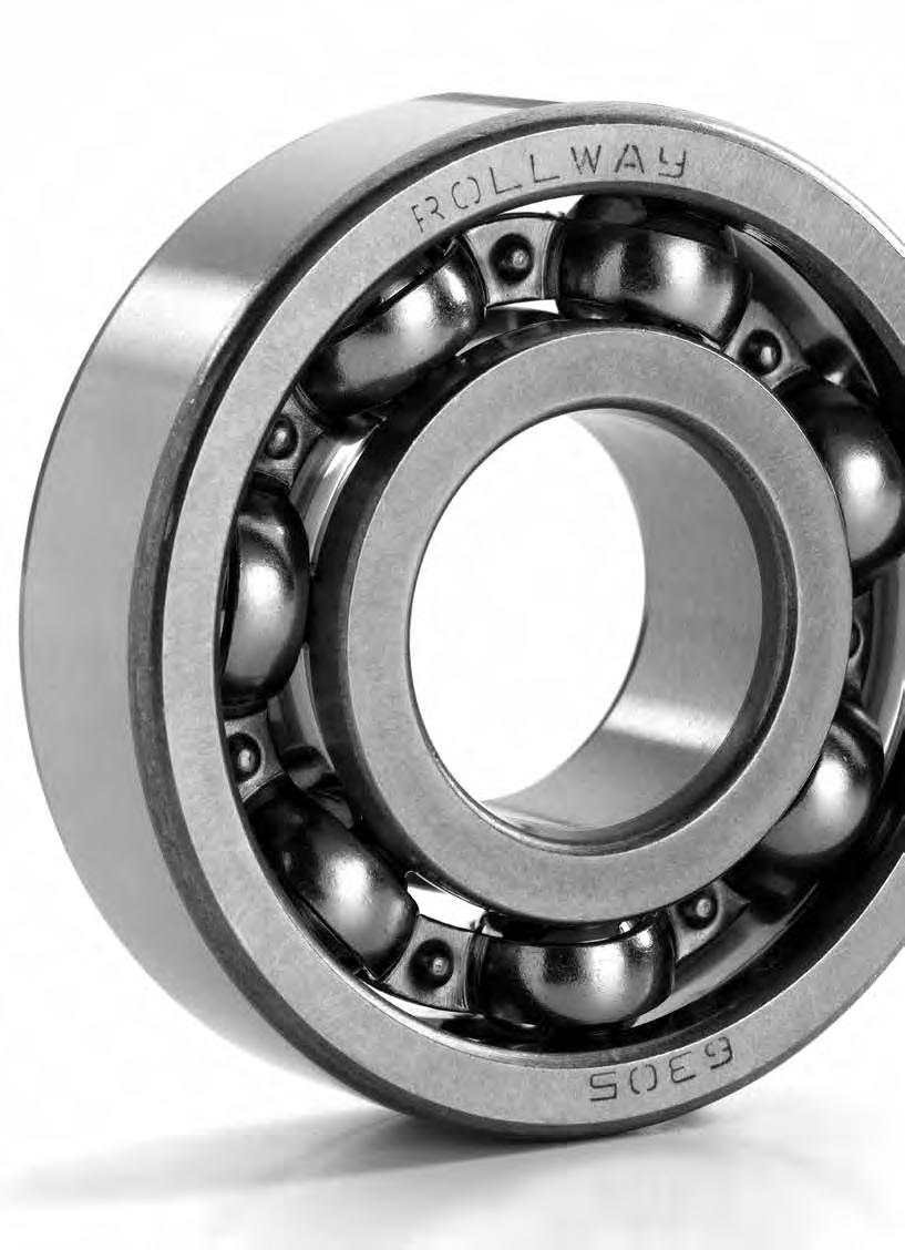
110
111 SINGLE ROW DEEP GROOVE BALL BEARINGS Dimensions in accordance with ISO The single row deep groove ball bearing is the most popular type of rolling bearing. Because the inner and outer raceway radii are only slightly larger than the ball diameter this in considerable axial load carrying capacity in either direction as well as radial loading. They are suitable for high speeds and can be supplied with shields or seals. ie. Suffix ZZ is added for shielded type and suffix 2RS is added for sealed type. The shielded type have a running clearance between the innerrace and the metal shield, whereas the seals, made from synthetic rubber, makes contact whit the inner race. Both shielded and sealed bearings are supplied with the correct amount of lithium base grease which has an operating temperature of -30 to +110 C. Cages are normally two pieced pressed steel. For higher speeds machined brass cages and reinforced plastics are used. Plastic cages are limited on operating temperature to about 120 C maximum. Deep groove ball bearings can also be supplied with snap ring and groove which provides a simple and space saving means of locating the bearing in the housing. Bearings with this feature have the suffix NR added to the designation. 109
112 Deep groove ball bearings Bearing ISO dimensions Load ratings Speed limits Weight Dim. Type Version d D B C Co Grease Oil rs mm kn kn r/min r/min kg min ,63 0, ,002 0,1 623 ZZ ,63 0, ,002 0, ,3 4, ,003 0,2 624 ZZ ,3 4, ,003 0, ,34 0, ,005 0,3 634 ZZ ,34 0, ,005 0, ,88 6, ,005 0,3 625 ZZ ,88 6, ,005 0, ,34 0, ,009 0,3 635 ZZ ,34 0, ,009 0, ,34 0, ,008 0,3 626 ZZ ,34 0, ,008 0, RS ,34 0, ,008 0, ,3 1, ,014 0,3 636 ZZ ,3 1, ,014 0, RS ,3 1,37 0,014 0, ,34 0, ,0075 0,3 607 ZZ ,34 0, ,0075 0, RS ,34 0,88 0,0075 0, ,3 1, ,013 0, ,56 1, ,024 0,3 637 ZZ ,56 1, ,024 0, RS ,56 1,98 0,024 0, ,3 1, ,012 0,3 110
113 Bearing ISO dimensions Load ratings Speed limits Weight Dim. Type Version d D B C Co Grease Oil rs mm kn kn r/min r/min kg min 608 ZZ ,3 1, ,012 0, RS ,3 1,37 0,012 0, ,35 1, ,017 0,3 628 ZZ ,35 1, ,017 0, RS ,35 1,43 0,017 0,3 628/6 ZZ ,08 0, , ,15 628/7 ZZ ,17 0, , , ,55 1, ,028 0,3 638 ZZ ,55 1, ,028 0, ,35 1, ,014 0,3 609 ZZ ,35 1, ,014 0, RS ,35 1,43 0,014 0, ,55 1, ,019 0,3 629 ZZ ,55 1, ,019 0, RS ,55 1,97 0,019 0, ,65 2, ,35 0,6 639 ZZ ,65 2, ,35 0, ,55 1, ,02 0, ZZ ,55 1, ,02 0, RS ,55 1,97 0,02 0, ,1 2, ,032 0, ZZ ,1 2, ,032 0, RS ,1 2,39 0,032 0, ,1 3, ,055 0,6 111
114 Deep groove ball bearings Bearing ISO dimensions Load ratings Speed limits Weight Dim. Type Version d D B C Co Grease Oil rs mm kn kn r/min r/min kg min 6300 ZZ ,1 3, ,055 0, RS ,1 3,45 0,055 0, ,7 0, ,005 0, ZZ ,7 0, ,005 0, ,95 0, ,01 0, ZZ ,95 0, ,01 0, ,1 2, ,021 0, ZZ ,1 2, ,021 0, RS ,1 2,37 0,021 0, ,8 3, ,038 0, ZZ ,8 3, ,038 0, RS ,8 3,05 0,038 0, ,7 4, , ZZ ,7 4, , RS ,7 4,2 0, ,1 2, ,026 0, ,8 0, ,006 0, ZZ ,8 0, ,006 0, ,9 1, ,011 0, ZZ ,9 1, ,011 0, ,6 2, ,028 0, ZZ ,6 2, ,028 0, RS ,6 2, ,028 0, ,75 3, ,045 0,5 112
115 Bearing ISO dimensions Load ratings Speed limits Weight Dim. Type Version d D B C Co Grease Oil rs mm kn kn r/min r/min kg min 6202 ZZ ,75 3, ,045 0, RS ,75 3, ,045 0, ,4 5, , ZZ ,4 5, , RS ,4 5,45 0, ,6 2, ,037 0, , ,007 0, ZZ , ,007 0, ,35 2, ,017 0, ZZ ,35 2, ,017 0, , ,035 0, ZZ , ,035 0, RS ,25 0,035 0, ,55 4, ,066 0, ZZ ,55 4, ,066 0, RS ,55 4, ,066 0, ,6 6, , ZZ ,6 6, , RS ,6 6,65 0, , ,04 0, ,2 1, ,009 0, ZZ ,2 1, ,009 0, ,35 2, ,018 0, ZZ ,35 2, ,018 0,3 113
116 Deep groove ball bearings Bearing ISO dimensions Load ratings Speed limits Weight Dim. Type Version d D B C Co Grease Oil rs mm kn kn r/min r/min kg min , ,063 0, ZZ , ,063 0, RS ,4 5 0,063 0, ,8 6, , ZZ ,8 6, , RS ,8 6,6 0, ,9 7, ,14 1, ZZ ,9 7, ,14 1, RS ,9 7,9 0,14 1, ,95 4, ,05 0, ,45 2, ,02 0, ZZ ,45 2, ,02 0, ,55 3, ,036 0, ZZ ,55 3, ,036 0, ,1 5, ,08 0, ZZ ,1 5, ,08 0, RS ,1 5,85 0,08 0, , , ZZ , , RS ,85 0, ,6 11, ,25 1, ZZ ,6 11, ,25 1, RS ,6 11,2 0,25 1, ,2 18, ,0575 1,5 114
117 Bearing ISO dimensions Load ratings Speed limits Weight Dim. Type Version d D B C Co Grease Oil rs mm kn kn r/min r/min kg min ,85 5, ,058 0, ,35 2, ,022 0, ZZ ,35 2, ,022 0, , ,041 0, ZZ , ,041 0, ,5 11, , ZZ ,5 11, , RS ,5 11, , ,9 15, ,371 1, ZZ ,9 15, ,371 1, RS ,9 15, ,371 1, ,3 24, ,785 1, ,2 7, , ,4 2, ,027 0, ,8 4, ,045 0, ,9 10, , ,7 15, ,315 1, ZZ ,7 15, ,315 1, RS ,7 15, ,315 1, ,5 18, ,45 1, ZZ ,5 18, ,45 1, RS ,5 18, ,45 1, ,5 29, ,954 1, ,2 8, ,111 0,3 115
118 Deep groove ball bearings Bearing ISO dimensions Load ratings Speed limits Weight Dim. Type Version d D B C Co Grease Oil rs mm kn kn r/min r/min kg min , ,031 0, ,5 6, ,073 0, ,8 11, , ZZ ,8 11, , RS ,8 11, , , ,402 1, ZZ , ,402 1, RS , ,402 1, , ,635 1, ZZ , ,635 1, RS , ,635 1, , ,3 9, ,13 0, ,5 10, ,111 0, , ZZ , RS , ,7 20, ,414 1, ZZ ,7 20, ,414 1, RS ,7 20, ,414 1, ,8 31, ,838 1, ZZ ,8 31, ,838 1, RS ,8 31, ,838 1, ,8 44, ,
119 Bearing ISO dimensions Load ratings Speed limits Weight Dim. Type Version d D B C Co Grease Oil rs mm kn kn r/min r/min kg min ,5 12, ,17 0, ,4 5, ,043 0, , ,12 0, ,8 16, , ZZ ,8 16, , RS ,8 16, , ,1 23, ,46 1, ZZ ,1 23, ,46 1, RS ,1 23, ,46 1, ,8 37, , ZZ ,8 37, , RS ,8 37, , , ,89 2, ,3 13, ,188 0, ,8 6, ,057 0, ,5 10, ,13 0, ,3 21, ,39 1, ZZ ,3 21, ,39 1, RS ,3 21, ,39 1, ,4 29, ,611 1, ZZ ,4 29, ,611 1, RS ,4 29, ,611 1, ,5 44, , ZZ ,5 44, ,
120 Deep groove ball bearings Bearing ISO dimensions Load ratings Speed limits Weight Dim. Type Version d D B C Co Grease Oil rs mm kn kn r/min r/min kg min RS ,5 44, , ,3 2, ,3 16, ,26 0, , ,083 0, ,4 23, ,42 1, ZZ ,4 23, ,42 1, RS ,4 23, ,42 1, , ,78 1, ZZ , ,78 1, RS , ,78 1, ,8 51, ,72 2, ZZ ,8 51, ,72 2, RS ,8 51, ,72 2, , ,76 2, , ,28 0, ,7 6, ,12 0, ,5 25, ,44 1, ZZ ,5 25, ,44 1, RS ,5 25, ,44 1, , ,995 1, ZZ , ,995 1, RS , ,995 1, ,7 59, ,1 2, ZZ ,7 59, ,1 2,1 118
121 Bearing ISO dimensions Load ratings Speed limits Weight Dim. Type Version d D B C Co Grease Oil rs mm kn kn r/min r/min kg min RS ,7 59, ,1 2, ,3 2, ,9 19, ,3 0, , ,13 0, ,1 30, ,6 1, ZZ ,1 30, ,6 1, RS ,1 30, ,6 1, ,2 44, ,07 1, ZZ ,2 44, ,07 1, RS ,2 44, ,07 1, , ,5 2, ZZ , ,5 2, RS , ,5 2, , , ,433 0, , ,16 0, RS ,7 21, , ,7 33, ,64 1, ZZ ,7 33, ,64 1, RS ,7 33, ,64 1, ,4 49, ,18 1, ZZ ,4 49, ,18 1, RS ,4 49, ,18 1, ,03 2,1 119
122 Deep groove ball bearings Bearing ISO dimensions Load ratings Speed limits Weight Dim. Type Version d D B C Co Grease Oil rs mm kn kn r/min r/min kg min 6315 ZZ ,03 2, RS ,03 2, , ,5 26, ,46 0, ,6 39, ,85 1, ZZ ,6 39, ,85 1, RS ,6 39, ,85 1, , , ZZ , , RS , , , ,6 2, ZZ , ,6 2, , ,9 29, ,6 0, ,9 13, ,16 0, ,1 20, , ,5 43, ,89 1, ZZ ,5 43, ,89 1, RS ,5 43, ,89 1, , , ZZ , , RS , , , , ZZ , ,
123 Bearing ISO dimensions Load ratings Speed limits Weight Dim. Type Version d D B C Co Grease Oil rs mm kn kn r/min r/min kg min ,8 33, , , , ,2 49, ,16 1, ZZ ,2 49, ,16 1, RS ,2 49, ,16 1, , , ZZ , , RS , , , ZZ , , ,9 40, , ,6 20, , ,5 53, ,2 1, ZZ ,5 53, ,2 1, RS ,5 53, ,2 1, , ,6 2, ZZ , ,6 2, , ,3 41, , , ,25 1, ZZ , ,25 1, RS , ,25 1,5 121
124 Deep groove ball bearings Bearing ISO dimensions Load ratings Speed limits Weight Dim. Type Version d D B C Co Grease Oil rs mm kn kn r/min r/min kg min ,1 2, ZZ ,1 2, ZZ , ,6 21, , ,3 65, , ZZ ,3 65, , ,7 2, , , ZZ , ,35 2, ZZ ,35 2, , M ,5 177, , ,5 56, , , , , ,84 1, , , ZZ , , ,15 2, ZZ ,15 2,1 122
125 Bearing ISO dimensions Load ratings Speed limits Weight Dim. Type Version d D B C Co Grease Oil rs mm kn kn r/min r/min kg min , ,2 63, , ,1 32, , , ZZ , ,93 1, ,93 1, , ZZ , , M , M ,5 272, , ,7 1, ,75 2, ZZ ,75 2, , , ,4 1, , ,4 1, M , , ,85 2,1 123
126 Deep groove ball bearings Bearing ISO dimensions Load ratings Speed limits Weight Dim. Type Version d D B C Co Grease Oil rs mm kn kn r/min r/min kg min 6032 ZZ ,85 2, M , , , ,6 1, ,49 1, M , ,8 2, , M , ,7 1, ,5 2, , M , ,3 78, , , , , , ,6 1, M , ,68 1, M ,63 2, M , M ,3 2, M ,
127 Bearing ISO dimensions Load ratings Speed limits Weight Dim. Type Version d D B C Co Grease Oil rs mm kn kn r/min r/min kg min M , ,21 1, M ,96 2, ,7 2, M , , , M , ,4 2, M , M ,1 2, M ,8 2, M , , M , M ,4 2, M M , M , M ,6 2, , , M ,4 2, ,
128 Deep groove ball bearings Bearing ISO dimensions Load ratings Speed limits Weight Dim. Type Version d D B C Co Grease Oil rs mm kn kn r/min r/min kg min , M ,4 2, ,5 2, , , ,6 2, , M , ,5 1, M ,2 2, M , MA , , , ,
129 Bearing ISO dimensions Load ratings Speed limits Weight Dim. Type Version d D B C Co Grease Oil rs mm kn kn r/min r/min kg min , M , ,5 2, M , , , , M , / ,1 618/500 M , / / / / / ,1 618/560 M , / / , /

130 Deep groove ball bearings Bearing ISO dimensions Load ratings Speed limits Weight Dim. Type Version d D B C Co Grease Oil rs mm kn kn r/min r/min kg min 609/ / / ,5 618/ , / /670 M / , / / / ,5 618/ / / ,5 608/ / / / ,5 608/ / / / ,5 618/900 CA / / ,5 128
131 Bearing ISO dimensions Load ratings Speed limits Weight Dim. Type Version d D B C Co Grease Oil rs mm kn kn r/min r/min kg min 619/ ,5 60/ ,5 608/ / / ,5 60/ ,5 618/ / ,5 60/ ,5 618/ / ,5 60/ ,5 619/ ,5 618/ / ,5 618/ ,5 619/ ,5 618/ ,5 619/ ,5 618/ ,5 619/ ,5 618/ ,5 619/ ,5 129
132 Deep groove ball bearings stainless steel Bearing ISO dimensions Load ratings Speed limits Weight Dim. Type Version d D B C Co Grease rs mm kn kn r/min kg min S685 2RS ,72 0, ,0011 0,15 S695 2RS ,08 0, ,0024 0,20 S605 2RS ,33 0, ,0035 0,20 S625 2RS ,76 0, ,0048 0,30 S635 2RS ,34 0, ,0080 0,30 S686 2RS ,08 0, ,0019 0,15 S696 2RS ,35 0, ,0038 0,20 S606 2RS ,19 0, ,0060 0,30 S626 2RS ,34 0, ,0080 0,30 S636 2RS ,30 1, ,0130 0,30 S687 2RS ,17 0, ,0021 0,15 S697 2RS ,61 0, ,0052 0,30 S607 2RS ,24 0, ,0080 0,30 S627 2RS ,35 1, ,0130 0,30 S637 2RS ,55 1, ,0240 0,30 S688 2RS ,26 0, ,0031 0,20 S698 2RS ,99 0, ,0073 0,30 S608 2RS ,35 1, ,0120 0,30 S628 2RS ,00 1, ,0170 0,30 S638 2RS ,55 1, ,0290 0,30 S689 2RS ,72 0, ,0032 0,20 S699 2RS ,48 1, ,0082 0,30 S609 2RS ,40 1, ,0140 0,30 S629 2RS ,55 1, ,0200 0,30 130
133 Bearing ISO dimensions Load ratings Speed limits Weight Dim. Type Version d D B C Co Grease rs mm kn kn r/min kg min S639 2RS ,00 2, ,0350 0,30 S6000 2RS ,55 1, ,0190 0,30 S6200 2RS ,10 2, ,0320 0,60 S6300 2RS ,20 3, ,0530 0,60 S6800 2RS ,83 0, ,0050 0,30 S6900 2RS ,70 1, ,0090 0,30 S6001 2RS ,10 2, ,0210 0,30 S6201 2RS ,10 2, ,0370 0,60 S6301 2RS ,70 4, ,0600 1,00 S6801 2RS ,92 1, ,0060 0,30 S6901 2RS ,89 1, ,0110 0,30 S6002 2RS ,60 2, ,0300 0,30 S6202 2RS ,75 3, ,0450 0,60 S6302 2RS ,40 5, ,0820 1,00 S6802 2RS ,08 1, ,0070 0,30 S6902 2RS ,10 2, ,0160 0,30 S6003 2RS ,80 3, ,0390 0,30 S6203 2RS ,60 4, ,0660 0,60 S6303 2RS ,50 6, ,1150 1,00 S6803 2RS ,81 1, ,0080 0,30 S6903 2RS ,65 2, ,0180 0,30 S6004 2RS ,40 5, ,0690 0,60 S6204 2RS ,80 6, ,1060 1,00 S6304 2RS ,90 7, ,1440 1,10 131
134 Deep groove ball bearings stainless steel Bearing ISO dimensions Load ratings Speed limits Weight Dim. Type Version d D B C Co Grease rs mm kn kn r/min kg min S6804 2RS ,00 2, ,0190 0,30 S6904 2RS ,40 3, ,0360 0,30 S6005 2RS ,10 5, ,0800 0,60 S6205 2RS ,00 7, ,1280 1,00 S6305 2RS ,20 10, ,2320 1,10 S6805 2RS ,30 2, ,0220 0,30 S6905 2RS ,05 4, ,0420 0,30 S6006 2RS ,20 8, ,1160 1,00 S6206 2RS ,50 11, ,1990 1,00 S6306 2RS ,70 15, ,3500 1,10 S6806 2RS ,70 3, ,0260 0,30 S6906 2RS ,25 5, ,0480 0,30 S6007 2RS ,00 10, ,1550 1,00 S6207 2RS ,70 15, ,2880 1,10 S6307 2RS ,50 19, ,4570 1,50 S6807 2RS ,90 4, ,0290 0,30 S6907 2RS ,20 7, ,0740 0,60 S6008 2RS ,80 11, ,1900 1,00 S6208 2RS ,10 17, ,3660 1,10 S6308 2RS ,50 24, ,6300 1,50 S6808 2RS ,10 4, ,0330 0,30 S6908 2RS ,60 10, ,1100 0,60 S6009 2RS ,00 15, ,2370 1,00 S6209 2RS ,50 20, ,3980 1,10 132
135 Bearing ISO dimensions Load ratings Speed limits Weight Dim. Type Version d D B C Co Grease rs mm kn kn r/min kg min S6309 2RS ,00 32, ,8140 1,50 S6809 2RS ,40 5, ,0400 0,30 S6909 2RS ,10 11, ,1280 0,60 S6010 2RS ,80 16, ,2610 1,00 S6210 2RS ,00 23, ,4540 1,10 S6310 2RS ,00 38, ,0700 2,00 S6810 2RS ,60 6, ,0520 0,30 S6910 2RS ,60 12, ,1320 0,60 S6011 2RS ,30 21, ,3880 1,10 S6211 2RS ,50 29, ,6010 1,50 S6311 2RS ,50 45, ,3700 2,00 S6811 2RS ,80 8, ,0830 0,30 S6911 2RS ,00 13, ,1800 1,00 S6012 2RS ,50 23, ,4140 1,10 S6212 2RS ,50 36, ,7830 1,50 S6812 2RS ,50 10, ,1060 0,30 S6912 2RS ,40 14, ,1930 1,00 S6013 2RS ,50 25, ,4210 1,10 S6213 2RS ,50 40, ,9900 1,50 S6813 2RS ,60 11, ,1280 0,60 S6913 2RS ,40 16, ,2060 1,00 S6014 2RS ,00 31, ,6040 1,10 S6814 2RS ,10 11, ,1370 0,60 S6914 2RS ,70 21, ,3340 1,00 133
136 Deep groove ball bearings stainless steel Bearing ISO dimensions Load ratings Speed limits Weight Dim. Type Version d D B C Co Grease rs mm kn kn r/min kg min S6815 2RS ,50 12, ,1450 0,60 S6915 2RS ,40 22, ,3530 1,00 S6816 2RS ,70 13, ,1540 0,60 S6916 2RS ,90 24, ,3730 1,00 134
137 135

138
139 SELF-ALIGNING BALL BEARINGS Dimensions in accordance with ISO Self aligning ball bearings have two rows of balls located on the inner ring and a spherical outer track. This design permits misalignment of the inner and outer races caused, for example, by shaft deflection or variation in housing alignment. These bearings are also manufactured with tapered bore for use with adapter sleeves. Misalignment Maximum permitted misalignment in degrees. Bearing series 108, 126, 127, 129, 135 Series 12 Series 13 Series 22 Series 22-2RS Series 23 Series 23-2RS Maximum inclination in degrees Self-aligning ball bearings with cylindrical and tapered bore Sellf-aligning ball bearings with adapter sleeve tapered bore
140 Self aligning spherical ball bearings Bearing ISO dimensions Load ratings Speed limits Weight Dim. Calculation factors Type Version d D B C Co Grease Oil r1,2 e Y1 Y2 Y0 mm kn kn r/min r/min kg min ,55 0, ,01 0,3 0,33 1, ,5 0, ,01 0,3 0,33 1, ,65 0, ,01 0,3 0,33 1, ,65 0, ,01 0,3 0,33 1, ,8 0, ,02 0,6 0,33 1, ,5 1, ,03 0,6 0,33 1, ,2 1, ,62 0,6 0,34 1,9 2,9 1, ,2 1, ,04 0,6 0,54 1,2 1,8 1, ,6 1, ,04 0,6 0,37 1,7 2,6 1, ,4 2, ,06 1 0,35 1,8 2,8 1, ,6 1, ,05 0,6 0,53 1,2 1,8 1, ,4 2, ,09 1 0,54 1,2 1,8 1, ,5 1, ,04 0,6 0,36 1,8 2,7 1, ,55 2, ,09 1 0,35 1,8 2,8 1, ,7 1, ,06 0,6 0,5 1,3 2 1, ,1 2, ,11 1 0,5 1,3 2 1, ,9 2, ,07 0,6 0,32 1, ,5 3, ,13 1 0,34 1,8 2, ,8 2, ,08 0,6 0,5 1,3 2 1, ,5 3, ,16 1 0,49 1,3 2 1, ,9 2, ,120 1,0 0,28 2,2 3,5 2, ,4 3, ,160 1,1 0,30 2,1 3,3 2, ,6 3, ,140 1,0 0,28 2,2 3,5 2, ,2 4, ,210 1,1 0,52 1,2 1,9 1,3 138
141 Bearing ISO dimensions Load ratings Speed limits Weight Dim. Calculation factors Type Version d D B C Co Grease Oil r1,2 e Y1 Y2 Y0 mm kn kn r/min r/min kg min ,2 3, ,140 1,0 0,29 2,2 3,4 2, ,8 4, ,260 1,1 0,28 2,2 3,5 2, RS ,2 3, ,160 1,0 0,29 2,2 3,4 2, ,5 3, ,160 1,0 0,43 1,5 2,3 1, RS ,8 4, ,330 1,1 0,28 2,2 3,5 2, ,5 6, ,340 1,1 0,44 1,4 2,2 1, ,7 4, ,220 1,0 0,25 2,5 3,9 2, ,4 6, ,380 1,1 0,24 2,6 4,1 2, RS ,7 4, ,260 1,0 0,25 2,5 3,9 2, ,3 4, ,260 1,0 0,40 1,6 2,5 1, RS ,4 6, ,500 1,1 0,24 2,6 4,1 2, ,4 8, ,500 1,1 0,40 1,6 2,5 1, ,8 5, ,320 1,1 0,23 2,8 4,2 2, ,1 7, ,510 1,5 0,25 2,5 3,9 2, RS ,8 5, ,400 1,1 0,23 2,8 4,2 2, ,7 6, ,400 1,1 0,37 1,7 2,6 1, RS ,1 7, ,670 1,5 0,25 2,5 3,9 2, ,7 12, ,670 1,5 0,43 1,5 2,3 1, ,2 6, ,410 1,1 0,22 2,9 4,5 3, ,5 9, ,710 1,5 0,24 2,6 4,1 2, RS ,2 6, ,500 1,1 0,22 2,9 4,5 3, ,4 7, ,500 1,1 0,33 1,9 3,0 2, RS ,5 9, ,920 1,5 0,24 2,6 4,1 2, ,9 15, ,920 1,5 0,39 1,6 2,5 1,7 139
142 Self aligning spherical ball bearings Bearing ISO dimensions Load ratings Speed limits Weight Dim. Calculation factors Type Version d D B C Co Grease Oil r1,2 e Y1 Y2 Y0 mm kn kn r/min r/min kg min ,8 7, ,460 1,1 0,21 3,0 4,7 3, ,7 12, ,950 1,5 0,24 2,6 4,1 2, RS ,8 7, ,540 1,1 0,21 3,0 4,7 3, ,3 8, ,540 1,1 0,31 2,0 3,1 2, RS ,7 12, ,230 1,5 0,24 2,6 4,1 2, ,1 16, ,230 1,5 0,31 2,0 3,1 2, ,9 8, ,520 1,1 0,21 3,0 4,7 3, ,4 14, ,210 2,0 0,24 2,6 4,1 2, RS ,9 8, ,590 1,1 0,21 3,0 4,6 3, ,3 8, ,590 1,1 0,29 2,2 3,4 2, RS ,4 14, ,640 2,0 0,24 2,6 4,1 2, ,4 20, ,230 2,0 0,42 1,5 2,3 1, ,6 10, ,700 1,5 0,20 3,2 4,9 3, ,3 18, ,580 2,0 0,23 2,3 4,2 2, ,5 9, ,810 1,5 0,27 2,3 3,6 2, ,3 23, ,100 2,0 0,41 1,5 2,4 1, ,2 11, ,900 1,5 0,19 3,4 5,2 3, ,1 20, ,960 2,1 0,23 2,8 4,2 2, ,8 12, ,100 1,5 0,28 2,2 3,5 2, ,1 28, ,600 2,1 0,41 1,5 2,4 1, ,0 12, ,150 1,5 0,17 3,7 5,7 3, ,0 22, ,450 2,1 0,23 2,8 4,2 2, ,6 16, ,450 1,5 0,28 2,2 3,5 2, ,6 32, ,250 2,1 0,38 1,7 2,6 1,7 140
143 Bearing ISO dimensions Load ratings Speed limits Weight Dim. Calculation factors Type Version d D B C Co Grease Oil r1,2 e Y1 Y2 Y0 mm kn kn r/min r/min kg min ,6 13, ,250 1,5 0,18 3,5 5,4 3, ,1 27, ,000 2,1 0,22 2,9 4,5 3, ,2 17, ,500 1,5 0,27 2,3 3,6 2, ,0 31, ,900 2,1 0,35 1,8 2,8 1, ,9 15, ,350 1,5 0,18 3,5 5,4 3, ,2 30, ,550 2,1 0,22 2,9 4,5 3, ,0 17, ,600 1,5 0,25 2,5 3,9 2, ,0 42, ,700 2,1 0,38 1,7 2,6 1, ,8 17, ,650 2,0 0,16 3,9 6,1 4, ,4 33, ,200 2,1 0,22 2,9 4,5 3, ,8 19, ,000 2,0 0,26 2,4 3,7 2, ,0 48, ,100 2,1 0,34 1,9 2,9 2, ,2 20, ,050 2,0 0,17 3,7 5,7 3, ,5 37, ,000 3,0 0,22 2,9 4,5 3, ,5 23, ,500 2,0 0,25 2,5 3,9 2, ,0 51, ,050 3,0 0,37 1,7 2,6 1, ,0 23, ,500 2,0 0,17 3,7 5,7 3, ,0 44, ,800 3,0 0,22 2,9 4,5 3, ,2 27, ,400 2,0 0,27 2,3 3,6 2, ,0 57, ,450 3,0 0,38 1,7 2,6 1, ,7 24, ,100 2,1 0,17 3,7 5,7 3, ,0 50, ,700 3,0 0,23 2,8 4,2 2, ,9 29, ,700 2,1 0,17 3,7 5,7 3, ,0 57, ,300 3,0 0,24 2,6 4,1 2,8 141
144 Self aligning spherical ball bearings Bearing ISO dimensions Load ratings Speed limits Weight Dim. Calculation factors Type Version d D B C Co Grease Oil r1,2 e Y1 Y2 Y0 mm kn kn r/min r/min kg min ,5 34, ,000 2,1 0,24 2,6 4,1 2, ,0 73, ,200 3,0 0,34 1,9 2,9 2, ,0 35, ,150 2,1 0,17 3,7 5,7 3, ,0 67, ,000 3,0 0,22 2,9 4,5 3, ,0 48, ,100 2,1 0,26 2,4 3,7 2,5 142
145 143
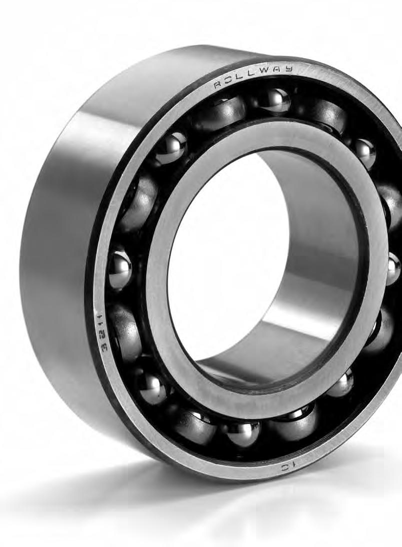
146
147 ANGULAR CONTACT BALL BEARINGS Dimensions in accordance with ISO Single row, angular contact ball bearings are especially designed to carry combination radial and single direction thrust loads. To carry thrust loads from opposing directions, these bearings are frequently mounted in duplex pairs with the contact angles opposed. Angular contact bearings can be mounted in a variety of ways ie. Face to Face and Tandem as illustrated. Bearings are also available with universally flush ground side surfaces of the inner and outer rings for duplex mountings. Flush ground bearings are available in different preloads to give axial rigidity. Angular contact bearings are offered in extra light, light and medium series. Each series is available in 15, 25 and 40 contact angles to fulfill a wide variety of applications. A higher contact angle increases thrust capacity and axial rigidity but reduces radial capacity and radial rigidity. Pressed steel, machined bronze, and phenolic cages are available to meet a variety of speed and duty requirements. SINGLE ROW ANGULAR CONTACT BALL BEARINGS Serie 72 B, 73 B Serie 70 A, 72 A Serie 70 C, 72 C Contact angle Contact angle Contact angle α= 40 α= 25 α= 15 DT arrangement DB arrangement DF arrangement (tandem) (back to back) (face to face) 145

148 Single row angular contact ball bearings Bearing Type Load ratings Speed limits Weight Dimensions Type Version d D B C Co Grease Oil r1,2 r3,4 a mm kn kn r/min r/min kg min min 7200 B ,95 2, ,031 0,6 0, B ,4 3, ,045 0,6 0, B ,45 3, ,048 0,6 0, B ,90 6, ,090 1,0 0, B ,9 5, ,065 0,6 0, B TN ,9 5, ,065 0,6 0, B ,8 8, ,120 1,0 0, B ,1 8, ,110 1,0 0, B ,3 9, ,150 1,1 0, B ,5 10, ,130 1,0 0, B ,4 14, ,250 1,1 0, B ,5 13, ,210 1,0 0, B ,3 19, ,370 1,1 0, B ,5 19, ,300 1,1 0, B ,7 24, ,510 1,5 1, B ,1 23, ,390 1,1 0, B ,8 30, ,670 1,5 1, B ,1 26, ,440 1,1 0, B ,3 40, ,900 1,5 1, B ,4 28, ,490 1,1 0, B ,2 47, ,150 2,0 1, B ,2 36, ,650 1,5 1, B ,8 56, ,450 2,0 1, B ,3 44, ,840 1,5 1, B ,0 65, ,850 2,1 1, B ,6 52, ,050 1,5 1, B ,0 75, ,250 2,1 1, B ,1 57, ,150 1,5 1,
149 Bearing Type Load ratings Speed limits Weight Dimensions Type Version d D B C Co Grease Oil r1,2 r3,4 a mm kn kn r/min r/min kg min min 7314 B ,0 86, ,750 2,1 1, B ,8 63, ,300 1,5 1, B ,0 97, ,300 2,1 1, B ,5 69, ,550 2,0 1, B ,0 109, ,900 2,1 1, B ,1 81, ,950 2,0 1, B ,0 122, ,600 3,0 1, B ,0 93, ,400 2,0 1, B ,0 135, ,400 3,0 1, B ,0 101, ,900 2,1 1, B ,0 150, ,250 3,0 1, B ,0 116, ,450 2,1 1, B ,0 178, ,750 3,0 1, B ,0 145, ,800 2,1 1, B ,0 229, ,500 3,0 1, B ,0 334, ,600 4,0 1,

150 Double rows angular contact ball bearings Bearing ISO dimensions Load ratings Speed limits Weight Dimensions Type Version d D B C Co Grease Oil r1,2 a mm kn kn r/min r/min kg min ,3 7,8 3, ,05 0, ,9 10,6 5, ,06 0, ,9 11,8 6, ,07 0, ,3 8, , ,5 14,6 7, ,1 0, ,2 20,8 10, , ,6 19,6 10, ,170 1, ,2 23,2 12, ,230 1, ,6 21,2 12, ,190 1, ,4 29,2 17, ,370 1, ,8 28,1 18, ,310 1, ,2 38,0 24, ,580 1, ,0 39,0 25, ,480 1, ,9 51,0 30, ,780 1, ,2 48,0 31, ,650 1, ,5 62,0 39, ,050 1, ,2 49,0 32, ,700 1, ,7 71,0 57, ,410 1, ,2 51,0 36, ,740 1, ,4 85,0 75, ,900 2, ,3 54,0 55, ,050 1, ,2 98,0 88, ,480 2, ,5 69,5 72, ,360 1, ,0 114,0 112, ,170 2,
151 Bearing ISO dimensions Load ratings Speed limits Weight Dimensions Type Version d D B C Co Grease Oil r1,2 a mm kn kn r/min r/min kg min ,1 73,5 83, ,760 1, ,7 129,0 130, ,010 2, ,7 81,5 91, ,930 1, ,5 143,0 146, ,040 2, ,3 85,0 98, ,080 1, ,3 163,0 166, ,160 2, ,4 95,0 110, ,640 2, ,3 176,0 186, ,930 2, ,2 112,0 132, ,390 2, ,0 190,0 200, ,300 3, ,4 125,0 146, ,140 2, ,0 216,0 240, ,230 3, ,6 140,0 163, ,000 2, ,8 220,0 245, ,400 3, ,3 160,0 196, ,100 2, ,6 240,0 280, ,200 3, ,8 190,0 228, ,790 2, ,1 280,0 400, ,000 3,
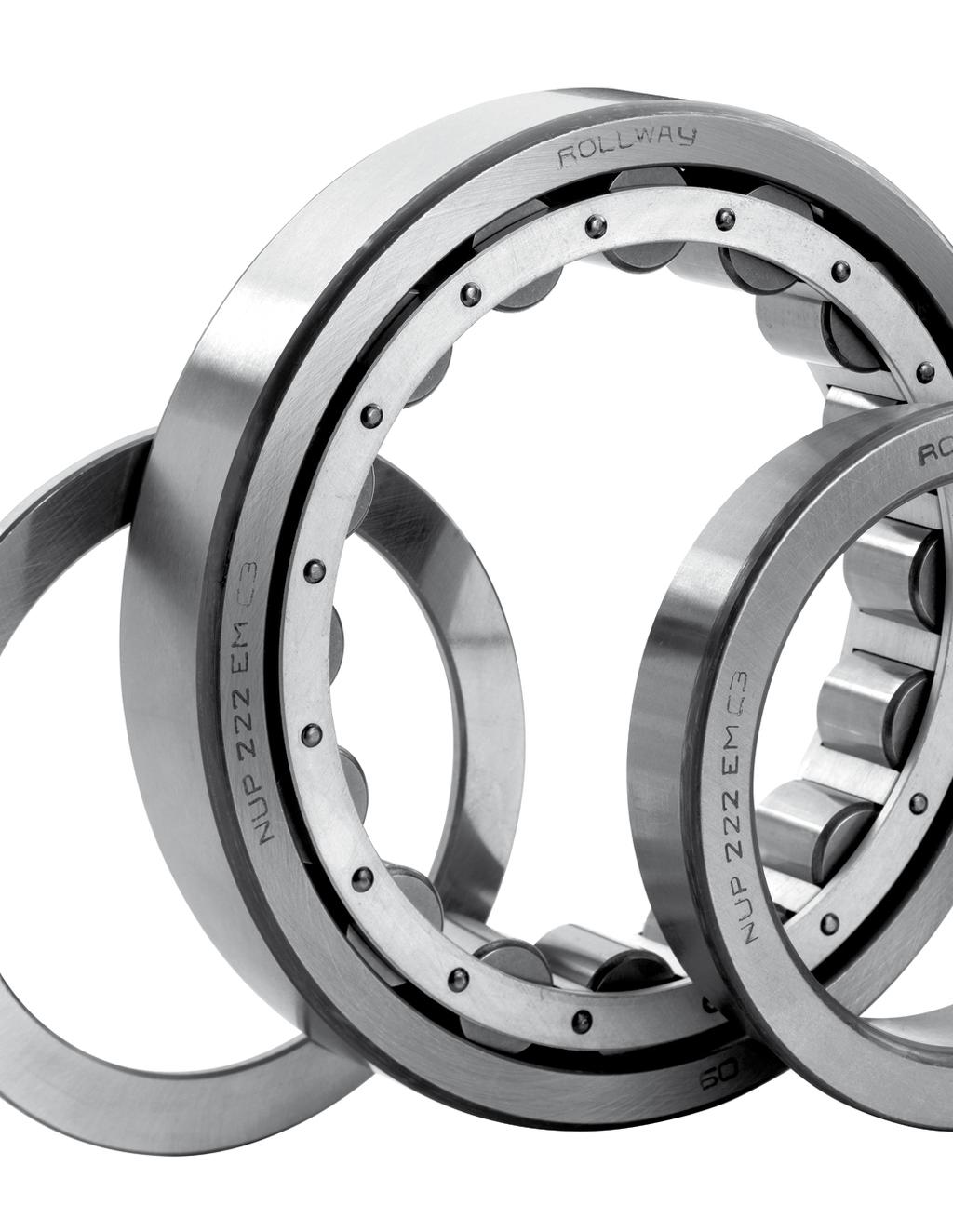
152
153 CYLINDRICAL ROLLER BEARINGS Dimensions in accordance with ISO Cylindrical roller bearings are manufactured in a number of designs as indicated on the following page; the predominant type being the single row roller. The roller and cage assembly are guided axially by the integral flanges (ribs) on one of the bearing rings. This design facilitates ease of mounting and dismounting, particularly where both races are an interference fit on their seatings. Roller bearings with flanges (ribs) on one race only do not provide any end location. Various roller bearings with ribs on both races provide axial location, and are capable of carrying light or intermittent axial loading. These patterns are of the NJ, NUP and NJ+HJ types. If used for axial location and light axial loads the contact between the flanges (ribs) and the roller ends is that of a sliding bearing, not rolling bearing, therefore lubrication is of paramount importance. Alignment is much more critical than that of a ball bearing, as a general guide this is limited to approximately.003 radians. Double and multi-row bearings are also manufactured, see NN and NNU series. NU NJ NUP N NJ+HJ Of these bearings, the NJ, NUP and NJH types can also carry light or intermittent thrust loads between the guide rib and the end of the rollers. Several arrangements of locating ribs are available as illustrated. The choice between these types is usually decided by considerations of assembly procedure or machine clearances. The bearings utilizing machined bronze cages are suitable for high speed operation. The NN 30 and NN 30 K series are available in high precision tolerances and due to their extreme rigidity, are particularly suited for use in machine tool spindles. 151
154 Single row cylindrical roller bearings Bearing ISO dimensions Load ratings Speed limits Weight Dimensions Type Version d D B C Co Grease Oil F E r s r 1s mm kn kn r/min r/min kg min min NU 202 E ,5 11, ,052 19,3 0,6 0,3 NJ 202 EM ,5 11, ,055 19,3 0,6 0,3 NJ , ,091 22,1 0,6 0,3 NU , ,064 22,9 0,6 0,3 NU 203 M , ,08 22,1 0,6 0,3 NU 203 EM ,6 14, ,01 22,1 0,6 0,3 NU , ,067 22,9 0,6 0,3 NU 2203 E ,4 19, ,097 22,1 0,6 0,3 NU , ,12 25,1 1 0,6 NUP , ,089 22,9 0,6 0,3 NUP2203 E ,4 19, ,089 22,1 0,6 0,3 N ,2 12, ,11 40,0 1 0,6 NJ ,2 12, ,11 27,0 1 0,6 NJ 204 E ,7 22, ,11 26,5 1 0,6 NJ 204 EM ,7 22, ,11 26,5 1 0,6 NJ ,7 18, ,142 26,5 1 0,6 NJ 2204 E ,6 28, ,142 26,5 1 0,6 NJ 2204 EM ,6 28, ,142 26,5 1 0,6 NJ 2304 EM , ,207 27,5 1,1 0,6 NJ 2304 E , ,207 27,5 1,1 0,6 NJ ,1 17, ,152 27,5 1,1 0,6 NJ 304 EM ,7 26, ,14 28,5 1,1 0,6 NU ,2 12, ,11 27,0 1 0,6 NU 204 E ,7 22, ,11 26,5 1 0,6 152
155 Bearing ISO dimensions Load ratings Speed limits Weight Dimensions Type Version d D B C Co Grease Oil F E r s r 1s mm kn kn r/min r/min kg min min NU 204 EM , ,124 27,0 1 0,6 NU ,7 18, ,14 27,0 1 0,6 NU 2204 E ,6 28, ,14 27,0 1 0,6 NU 2204 EM ,5 28, ,137 26,5 1 0,6 NU 2304 EM , ,22 27,5 1,1 0,6 NU 2304 E , ,207 27,5 1,1 0,6 NU ,1 17, ,152 27,5 1,1 0,6 NU 304 EM ,7 26, ,14 28,5 1,1 0,6 NUP 204 EM ,7 22, ,11 26,5 1 0,6 NUP 204 E ,7 22, ,11 26,5 1 0,6 NUP 2204 E ,6 28, ,14 28,5 1 0,6 NUP ,1 17, ,152 27,5 1,1 0,6 NUP 304 EM ,7 26, ,22 27,5 1,1 0,6 NUP 2304 EM , ,084 30,5 1,1 0,6 N ,7 15, ,16 31,5 1 0,6 N ,3 25, ,24 53,0 1,1 1,1 N 305 EM , ,243 54,0 1,1 1,1 NJ ,7 15, ,14 32,0 1 0,6 NJ 205 E ,5 26, ,14 31,5 1 0,6 NJ 205 EM ,5 26, ,14 31,5 1 0,6 NJ 205 E ,5 26, ,14 31,5 1 0,6 NJ 2205 E ,6 34, ,16 31,5 1 0,6 NJ 2205 EM ,6 34, ,17 31,5 1 0,6 NJ ,3 25, ,24 35,0 1,1 1,1 153
156 Single row cylindrical roller bearings Bearing ISO dimensions Load ratings Speed limits Weight Dimensions Type Version d D B C Co Grease Oil F E r s r 1s mm kn kn r/min r/min kg min min NJ 305 E , ,24 34,0 1,1 1,1 NJ 305 M ,3 35, ,28 35,0 1,1 1,1 NJ 305 EM , ,243 34,0 1,1 1,1 NJ 2305 E ,7 55, ,348 34,0 1,1 1,1 NJ 2305 EM ,7 55, ,348 34,0 1,1 1,1 NU ,4 20, ,14 32,0 0,6 0,3 NU ,7 15, ,14 31,5 1 0,6 NU 205 E ,5 26, ,14 31,5 1 0,6 NU 205 EM ,5 26, ,14 31,5 1 0,6 NU 205 E ,5 26, ,14 31,5 1 0,6 NU 2205 E ,6 34, ,17 31,5 1 0,6 NU 2205 EM ,6 34, ,17 31,5 1 0,6 NU 305 E ,3 25, ,243 34,0 1,1 1,1 NU 305 EM ,3 25, ,243 34,0 1,1 1,1 NU 305 M ,3 25, ,243 35,0 1,1 1,1 NU 2305 EM ,7 55, ,348 34,0 1,1 1,1 NU 2305 E ,7 55, ,34 34,0 1,1 1,1 NU , ,629 38,8 1,1 1,1 NU 405 M ,6 44, ,61 38,8 1,5 1,5 NUP 205 E ,5 26, ,14 31,5 1 0,6 NUP 2205 E ,6 34, ,16 31,5 1 0,6 NUP 2205 EM ,6 34, ,17 31,5 1 0,6 NUP 2305 E ,7 55, ,352 34,0 1,1 1,1 NUP 305 M ,7 31, ,3 34,0 1,1 1,1 154
157 Bearing ISO dimensions Load ratings Speed limits Weight Dimensions Type Version d D B C Co Grease Oil F E r s r 1s mm kn kn r/min r/min kg min min NUP 305 EM , ,3 34,0 1,1 1,1 NUP 405 M ,6 44, ,65 38,8 1,5 1,5 N ,4 21, ,206 55,5 1 0,6 N 206 EM ,7 37, ,26 55,5 1 0,6 N ,7 35, ,35 62,0 1,1 1,1 N ,4 50, ,53 62,0 1,1 1,1 NJ ,4 21, ,2 38,5 1 0,6 NJ 206 E ,7 37, ,2 37,5 1 0,6 NJ 206 EM ,7 37, ,2 37,5 1 0,6 NJ 206 E ,7 37, ,2 37,5 1 0,6 NJ ,8 33, ,26 38,5 1 0,6 NJ 2206 EM ,9 49, ,251 37,5 1 0,6 NJ 2206 E ,9 49, ,255 37,5 1 0,6 NJ 306 E , ,35 40,5 1,1 1,1 NJ 306 EM , ,37 40,5 1,1 1,1 NJ ,4 50, ,53 42,0 1,1 1,1 NJ 2306 EM , ,52 40,5 1,1 1,1 NJ 2306 E , ,52 40,5 1,1 1,1 NJ 406 M , ,867 45,0 1,5 1,5 NJ 406 M , ,867 45,0 1,5 1,5 NU ,4 21, ,2 38,5 1 0,6 NU 206 E ,7 37, ,206 37,5 1 0,6 NU 206 EM ,7 37, ,206 37,5 1 0,6 NU ,8 33, ,26 38,5 1 0,6 155
158 Single row cylindrical roller bearings Bearing ISO dimensions Load ratings Speed limits Weight Dimensions Type Version d D B C Co Grease Oil F E r s r 1s mm kn kn r/min r/min kg min min NU 2206 E ,9 49, ,26 37,5 1 0,6 NU 2206 M , ,3 37,5 1 0,6 NU 2206 EM ,9 49, ,26 37,5 1 0,6 NU 2206 E ,9 49, ,255 37,5 1 0,6 NU 306 E , ,37 40,5 1,1 1,1 NU 306 EM , ,37 40,5 1,1 1,1 NU 306 E , ,35 40,5 1,1 1,1 NU 306 M ,7 35, ,37 42,0 1,1 1,1 NU , ,75 45,0 1,5 1,5 NU 406 M , ,867 45,0 1,5 1,5 NU ,4 50, ,53 42,0 1,1 1,1 NU 2306 E , ,5 40,5 1,1 1,1 NUP 206 E ,7 37, ,2 37,5 1 0,6 NUP 206 EM ,7 37, ,2 37,5 1 0,6 NUP 206 E ,7 37, ,2 37,5 1 0,6 NUP 206 M ,4 21, ,2 38,5 1 0,6 NUP ,8 33, ,255 38,5 1 0,6 NUP 2206 E ,9 49, ,255 37,5 1 0,6 NUP ,7 35, ,37 42,0 1,1 1,1 NUP 306 E , ,38 40,5 1,1 1,1 NUP ,4 50, ,53 42,0 1,1 1,1 NUP 2306 E , ,53 40,5 1,1 1,1 NUP 2306 EM , ,53 40,5 1,1 1,1 NUP 2306 E , ,53 40,5 1,1 1,1 156
159 Bearing ISO dimensions Load ratings Speed limits Weight Dimensions Type Version d D B C Co Grease Oil F E r s r 1s mm kn kn r/min r/min kg min min NUP 2306 M ,4 50, ,53 42,0 1,1 1,1 N ,6 31, ,303 61,8 1,1 0,6 N ,3 44, ,485 68,2 1,5 1,1 N 307 E ,8 61, ,47 70,2 1,5 1,1 N 307 EM ,8 61, ,47 70,2 1,5 NJ ,6 31, ,303 43,8 1,1 0,6 NJ 207 E ,9 49, ,303 44,0 1,1 0,6 NJ 207 EM ,9 49, ,303 44,0 1,1 0,6 NJ 207 M ,6 31, ,303 43,8 1,1 0,6 NJ , ,395 43,8 1,1 0,6 NJ 2207 E ,9 69, ,395 44,0 1,1 0,6 NJ 2207 EM ,9 69, ,395 44,0 1,1 0,6 NJ 2207 M , ,395 43,8 1,1 0,6 NJ 307 E ,8 61, ,49 46,2 1,5 1,1 NJ 307 EM ,8 61, ,485 46,2 1,5 1,1 NJ 307 EM , ,55 46,2 1,5 1,1 NJ 307 M ,3 44, ,485 46,2 1,5 1,1 NJ 307 M ,1 63, ,48 46,2 1,5 1,1 NJ ,3 57, ,72 46,2 1,5 1,1 NJ 2307 E ,5 89, ,727 46,2 1,5 1,1 NJ 2307 M ,3 57, ,72 46,2 1,5 1,1 NJ 407 M ,7 69, ,03 53,0 1,5 1,5 NU ,6 21, ,18 42,0 1 0,5 NU ,6 31, ,303 43,8 1,1 0,6 157
160 Single row cylindrical roller bearings Bearing ISO dimensions Load ratings Speed limits Weight Dimensions Type Version d D B C Co Grease Oil F E r s r 1s mm kn kn r/min r/min kg min min NU 207 E ,9 49, ,303 44,0 1,1 0,6 NU 207 EM ,9 49, ,303 44,0 1,1 0,6 NU , ,395 43,8 1,1 0,6 NU 2207 E ,9 69, ,395 44,0 1,1 0,6 NU 2207 EM ,9 69, ,395 44,0 1,1 0,6 NU 307 E ,8 61, ,485 46,2 1,5 1,1 NU 307 EM ,8 61, ,485 46,2 1,5 1,1 NU 307 M ,3 44, ,485 46,2 1,5 1,1 NU ,3 57, ,72 46,2 1,5 1,1 NU 2307 E ,5 89, ,696 46,2 1,5 1,1 NU 2307 M ,3 57, ,72 46,2 1,5 1,1 NU ,7 69, ,02 53,0 1,5 1,5 NU 407 M ,7 69, ,03 53,0 1,5 1,5 NUP ,6 31, ,303 43,8 1,1 0,6 NUP 207 E ,9 49, ,303 44,0 1,1 0,6 NUP , ,95 43,8 1,1 0,6 NUP 2207 E ,3 70, ,43 44,0 1,1 0,6 NUP 307 E ,8 61, ,485 46,2 1,5 1,1 NUP 307 EM ,8 61, ,485 46,2 1,5 1,1 NUP ,3 57, ,72 46,2 1,5 1,1 NUP 2307 E ,5 89, ,696 46,2 1,5 1,1 N ,7 42, ,38 70,0 1,1 1,1 N 208 EM , ,44 70,0 1,1 1,1 N ,2 53, ,66 77,5 1,5 1,5 158
161 Bearing ISO dimensions Load ratings Speed limits Weight Dimensions Type Version d D B C Co Grease Oil F E r s r 1s mm kn kn r/min r/min kg min min N 408 M ,8 86, ,31 92,0 2 2 NJ ,7 42, ,38 50,0 1,1 1,1 NJ 208 E ,6 51, ,38 49,5 1,1 1,1 NJ 208 EM ,6 51, ,38 49,5 1,1 1,1 NJ 208 M ,7 42, ,38 50,0 1,1 1,1 NJ , ,49 50,0 1,1 1,1 NJ 2208 E ,3 74, ,5 49,5 1,1 1,1 NJ 2208 EM ,3 74, ,5 49,5 1,1 1,1 NJ ,2 53, ,66 53,5 1,5 1,5 NJ 308 E ,9 77, ,68 52,0 1,5 1,5 NJ 308 EM ,9 77, ,68 52,0 1,5 1,5 NJ 308 M ,2 53, ,66 53,5 1,5 1,5 NJ , ,95 53,5 1,5 1,5 NJ 2308 E ,95 52,0 1,5 1,5 NJ 2308 EM ,95 52,0 1,5 1,5 NJ ,8 86, ,3 58,0 2 2 NJ 408 M ,8 86, ,31 58,0 2 2 NU 1008 M , ,223 47,0 1 0,6 NU ,7 42, ,38 50,0 1,1 1,1 NU 208 E ,6 51, ,38 49,5 1,1 1,1 NU 208 EM ,6 51, ,38 49,5 1,1 1,1 NU 208 E ,6 51, ,366 49,5 1,1 1,1 NU 208 M ,7 42, ,38 50,0 1,1 1,1 NU , ,49 50,0 1,1 1,1 159
162 Single row cylindrical roller bearings Bearing ISO dimensions Load ratings Speed limits Weight Dimensions Type Version d D B C Co Grease Oil F E r s r 1s mm kn kn r/min r/min kg min min NU 2208 EMA ,3 74, ,56 49,5 1,1 1,1 NU ,2 53, ,66 53,5 1,5 1,5 NU 308 E ,9 77, ,65 52,0 1,5 1,5 NU 308 EM ,9 77, ,65 52,0 1,5 1,5 NU 308 M ,2 53, ,66 53,5 1,5 1,5 NU 2308 E ,95 52,0 1,5 1,5 NU 2308 EM ,95 52,0 1,5 1,5 NU 2308 M , ,95 53,5 1,5 1,5 NU ,8 66, ,3 58,0 2 2 NU 408 M ,8 86, ,31 58,0 2 2 NUP ,7 42, ,38 50,0 1,1 1,1 NUP 208 EM ,6 51, ,391 49,5 1,1 1,1 NUP 208 E ,6 51, ,38 49,5 1,1 1,1 NUP 208 EM ,6 51, ,38 49,5 1,1 1,1 NUP , ,49 50,0 1,1 1,1 NUP 2208 E ,3 74, ,49 49,5 1,1 1,1 NUP 2208 EM ,3 74, ,49 49,5 1,1 1,1 NUP 308 E ,5 87, ,83 52,0 1,5 1,5 NUP 308 EM ,5 87, ,83 52,0 1,5 1,5 NUP , ,95 53,5 1,5 1,5 NUP 2308 E ,95 52,0 1,5 1,5 NUP 2308 EM ,95 52,0 1,5 1,5 NUP ,8 86, ,3 58,0 2 2 NUP 408 M ,8 86, ,31 58,
163 Bearing ISO dimensions Load ratings Speed limits Weight Dimensions Type Version d D B C Co Grease Oil F E r s r 1s mm kn kn r/min r/min kg min min N 209 M , ,445 75,0 1,1 1,1 N ,2 67, ,895 86,5 1,5 1,5 N 409 M , ,66 100,5 2 2 NJ , ,445 55,0 1,1 1,1 NJ 209 EM , ,519 NJ 209 E ,2 62, ,445 54,5 1,1 1,1 NJ ,2 67, ,53 55,0 1,1 1,1 NJ 2209 E ,1 84, ,55 54,5 1,1 1,1 NJ 2209 EM ,1 84, ,55 54,5 1,1 1,1 NJ 2209 M ,2 67, ,53 55,0 1,1 1,1 NJ 309 E ,9 97, ,895 58,5 1,5 1,5 NJ 309 EM ,9 97, ,895 58,5 1,5 1,5 NJ 309 M ,2 67, ,895 58,5 1,5 1,5 NJ ,29 58,5 1,5 1,5 NJ 2309 EM ,4 141, ,29 58,5 1,5 1,5 NJ 2309 M ,29 58,5 1,5 1,5 NJ ,2 111, ,7 64,5 1,5 1,5 NJ 409 M ,2 111, ,87 64,5 1,5 1,5 NU 1009 M ,4 34, ,289 52,5 1 0,6 NU , ,445 55,0 1,1 1,1 NU 209 E ,2 62, ,427 54,5 1,1 1,1 NU ,2 67, ,53 55,0 1,1 1,1 NU 2209 E ,1 84, ,55 54,5 1,1 1,1 NU 2209 EM ,1 84, ,55 54,5 1,1 1,1 161
164 Single row cylindrical roller bearings Bearing ISO dimensions Load ratings Speed limits Weight Dimensions Type Version d D B C Co Grease Oil F E r s r 1s mm kn kn r/min r/min kg min min NU 2209 M ,2 67, ,53 55,0 1,1 1,1 NU 309 E ,9 97, ,87 58,5 1,5 1,5 NU 309 EM ,9 97, ,895 58,5 1,5 1,5 NU 309 M ,2 67, ,895 58,5 1,5 1,5 NU ,29 58,5 1,5 1,5 NU 2309 M ,29 58,5 1,5 1,5 NU 2309 EM ,4 141, ,29 58,5 1,5 1,5 NU , ,66 64,5 2 2 NU 409 M , ,66 64,5 2 2 NUP , ,445 55,0 1,1 1,1 NUP 209 E ,2 62, ,445 54,5 1,1 1,1 NUP 209 EM , ,519 54,5 1,1 1,1 NUP ,2 67, ,53 55,0 1,1 1,1 NUP 2209 E ,9 81, ,53 54,5 1,1 1,1 NUP 309 E ,9 97, ,895 58,5 1,5 1,5 NUP 309 EM ,9 97, ,895 58,5 1,5 1,5 NUP 2309 E ,25 58,5 1,5 1,5 NUP 2309 EM ,4 141, ,29 58,5 1,5 1,5 NUP 2309 M ,29 58,5 1,5 1,5 NUP , ,64 64,5 2 2 NUP 409 M , ,66 64,5 2 2 N , ,49 60,4 1,1 1,1 N ,9 86, ,14 95,0 2 2 N 410 M ,01 110,8 2,1 2,1 162
165 Bearing ISO dimensions Load ratings Speed limits Weight Dimensions Type Version d D B C Co Grease Oil F E r s r 1s mm kn kn r/min r/min kg min min NJ 1010 M ,1 36, ,32 57,5 1 0,6 NJ 210 EM ,2 69, ,59 NJ , ,49 60,4 1,1 1,1 NJ 210 E ,7 68, ,499 59,5 1,1 1,1 NJ 210 M , ,49 60,4 1,1 1,1 NJ ,8 70, ,575 60,4 1,1 1,1 NJ 2210 E ,8 87, ,6 59,5 1,1 1,1 NJ 2210 EM ,8 87, ,6 59,5 1,1 1,1 NJ 2210 M ,8 70, ,575 60,4 1,1 1,1 NJ 310 E , NJ 310 EM , NJ 310 M ,9 86, , NJ 2310 E , NJ 2310 EM ,74 65,0 2 2 NJ 410 M ,08 70,8 2,1 2,1 NU 1010 M ,1 36, ,31 57,5 1 0,6 NU , ,49 60,4 1,1 1,1 NU 210 EM ,7 68, ,48 59,5 1,1 1,1 NU 210 E ,7 68, ,49 59,5 1,1 1,1 NU ,8 70, ,575 60,4 1,1 1,1 NU 2210 EM ,8 87, ,58 59,5 1,1 1,1 NU 2210 E ,8 87, ,58 59,5 1,1 1,1 NU 2210 M ,8 70, ,575 60,4 1,1 1,1 NU 310 E ,14 65,
166 Single row cylindrical roller bearings Bearing ISO dimensions Load ratings Speed limits Weight Dimensions Type Version d D B C Co Grease Oil F E r s r 1s mm kn kn r/min r/min kg min min NU 310 EM ,14 65,0 2 2 NU 2310 E ,74 65,0 2 2 NU 2310 EM ,74 65,0 2 2 NU 410 M ,01 70,8 2,1 2,1 NUP , ,49 60,4 1,1 1,1 NUP 210 E ,7 68, ,52 59,5 1,1 1,1 NUP ,8 70, ,575 60,4 1,1 1,1 NUP 2210 E ,8 87, ,6 59,5 1,1 1,1 NUP 2210 EM ,8 87, ,6 59,5 1,1 1,1 NUP 310 EM ,14 65,0 2 2 NUP 310 E ,21 65,0 2 2 NUP 2310 E ,74 65,0 2 2 N ,9 62, ,665 88,5 1,5 1,1 N 211 M ,9 62, ,665 88,5 1,5 1,1 N ,47 104,5 2 2 N ,54 117,2 2,1 2,1 NJ ,9 62, ,665 66,5 1,5 1,1 NJ 211 E ,6 93, ,66 66,0 1,5 1,1 NJ 211 EM ,6 93, ,66 66,0 1,5 1,1 NJ 2211 E , ,78 66,0 1,1 2 NJ 2211 EM , ,78 66,0 1,1 2 NJ 2211 M , ,78 66,5 1,5 1,1 NJ 311 E ,44 70,5 2 2 NJ 311 EM ,47 70,
167 Bearing ISO dimensions Load ratings Speed limits Weight Dimensions Type Version d D B C Co Grease Oil F E r s r 1s mm kn kn r/min r/min kg min min NJ 311 M ,47 70,5 2 2 NJ ,5 70,5 2 2 NJ 2311 EM ,86 70,5 2 2 NJ 2311 M ,23 70,5 2 2 NJ ,51 77,2 2,1 2,1 NJ 411 M ,54 77,2 2,1 2,1 NU 1011 M ,7 43, ,464 64,5 1,1 1 NU ,9 62, ,665 66,5 1,5 1,1 NU 211 E ,6 93, ,665 66,0 1,5 1,1 NU 211 EM ,6 93, ,665 66,0 1,5 1,1 NU 211 EM ,6 93, ,665 66,0 1,5 1,1 NU 2211 E , ,78 66,0 1,5 1,1 NU 2211 M , ,78 66,5 1,5 1,1 NU ,23 70,5 2 2 NU 2311 EM , ,5 70,5 2 2 NU 2311 M ,5 70,5 2 2 NU 311 EM ,47 70,5 2 2 NU 311 EMA ,47 70,5 2 2 NU ,51 77,2 2,1 2,1 NU 411 M ,54 77,2 2,1 2,1 NUP 211 E ,6 93, ,665 66,0 1,5 1,1 NUP 211 EM ,6 93, ,665 66,0 1,5 1,1 NUP 2211 EM , ,85 66,0 1,5 1,5 NUP 2211 E , ,85 66,0 1,5 1,5 165
168 Single row cylindrical roller bearings Bearing ISO dimensions Load ratings Speed limits Weight Dimensions Type Version d D B C Co Grease Oil F E r s r 1s mm kn kn r/min r/min kg min min NUP ,44 70,5 2 2 NUP 311 E ,47 70,5 2 2 NUP 311 EM ,47 70,5 2 2 NUP ,54 70,5 2 2 NUP 2311 EM , ,5 70,5 2 2 NUP ,51 77,2 2,1 2,1 N ,8 75, ,825 97,5 1,5 1,5 N 212 EM , , ,0 1,5 1,5 N ,85 113,0 2,1 2,1 N 312 M ,85 113,0 2,1 2,1 N ,78 223,0 2,1 2,1 NJ ,8 75, ,825 73,5 1,5 1,5 NJ 212 E , ,825 72,0 1,5 1,5 NJ 212 EM , ,825 72,0 1,5 1,5 NJ ,08 73,5 1,5 1,5 NJ 2212 E ,08 72,0 1,5 1,5 NJ ,88 77,0 2,1 2,1 NJ 312 E ,88 77,0 2,1 2,1 NJ 312 EM ,88 77,0 2,1 2,1 NJ 312 E ,88 77,0 2,1 2,1 NJ 312 M ,85 77,0 2,1 2,1 NJ ,78 77,0 2,1 2,1 NJ 2312 E ,77 77,0 2,1 2,1 NJ 2312 EM ,77 77,0 2,1 2,1 166
169 Bearing ISO dimensions Load ratings Speed limits Weight Dimensions Type Version d D B C Co Grease Oil F E r s r 1s mm kn kn r/min r/min kg min min NJ 2312 EMA ,77 77,0 2,1 2,1 NJ ,07 83,0 2,1 2,1 NJ 412 M ,07 83,0 2,1 2,1 NU 1012 EM ,8 43, ,47 68,5 1,1 1 NU 1012 M ,8 43, ,48 69,5 1,1 1 NU ,8 75, ,825 73,5 1,5 1,5 NU 212 E , ,825 72,0 1,5 1,5 NU 212 EM , ,825 72,0 1,5 1,5 NU ,08 73,5 1,5 1,5 NU 2212 E ,08 72,0 1,5 1,5 NU 2212 EM ,08 72,0 1,5 1,5 NU ,85 77,0 2,1 2,1 NU 312 E ,83 77,0 2,1 2,1 NU 312 EM ,83 77,0 2,1 2,1 NU 312 E ,83 77,0 2,1 2,1 NU 312 M ,85 77,0 2,1 2,1 NU ,85 77,0 2,1 2,1 NU 2312 E ,78 77,0 2,1 2,1 NU 2312 EM ,69 77,0 2,1 2,1 NU 2312 M ,78 77,0 2,1 2,1 NU ,78 83,0 2,1 2,1 NU 412 M ,78 83,0 2,1 2,1 NUP 212 E , ,87 72,0 1,5 1,5 NUP ,08 73,5 1,5 2,1 167
170 Single row cylindrical roller bearings Bearing ISO dimensions Load ratings Speed limits Weight Dimensions Type Version d D B C Co Grease Oil F E r s r 1s mm kn kn r/min r/min kg min min NUP 2212 EM ,08 72,0 1,5 2,1 NUP 2212 E ,08 72,0 1,5 2,1 NUP 312 EM ,85 77,0 2,1 2,1 NUP 312 E ,93 77,0 2,1 2,1 NUP 312 M ,85 77,0 2,1 2,1 NUP ,77 77,0 2,1 2,1 NUP 2312 E ,78 77,0 2,1 2,1 NUP 2312 EM ,78 77,0 2,1 2,1 NUP 2312 EMA ,78 77,0 2,1 2,1 NUP ,02 83,0 2,1 2,1 NUP 412 M ,07 83,0 2,1 2,1 N ,5 89, ,05 105,6 1,5 1,5 N ,24 121,5 2,1 2,1 N 313 EM ,24 124,5 2,1 2,1 N 313 M ,24 121,5 2,1 2,1 NJ ,5 89, ,05 79,6 1,5 1,5 NJ 213 E ,07 78,5 1,5 1,5 NJ 213 EM ,07 78,5 1,5 1,5 NJ ,45 79,6 1,5 1,5 NJ 2213 EM ,65 78,5 1,5 1,5 NJ ,24 83,5 2,1 2,1 NJ 313 E ,3 82,5 2,1 2,1 NJ 313 EM ,24 82,5 2,1 2,1 NJ 313 EM ,3 82,5 2,1 2,1 168
171 Bearing ISO dimensions Load ratings Speed limits Weight Dimensions Type Version d D B C Co Grease Oil F E r s r 1s mm kn kn r/min r/min kg min min NJ 313 M ,24 83,5 2,1 2,1 NJ 2313 EM ,35 82,5 2,1 2,1 NJ 413 M ,68 89,3 2,1 2,1 NU 1013 M , ,07 74,5 1,1 1 NU ,5 89, ,07 79,6 1,5 1,5 NU 213 E ,05 78,5 1,5 1,5 NU 213 EM ,05 78,5 1,5 1,5 NU 213 E ,523 78,5 1,5 1,5 NU 213 M ,5 89, ,05 79,6 1,5 1,5 NU ,45 79,6 1,5 1,5 NU 2213 EM ,65 78,5 1,5 1,5 NU 313 E ,65 78,5 2,1 2,1 NU 313 EM ,24 82,5 2,1 2,1 NU 313 M ,24 83,5 2,1 2,1 NU 2313 E ,31 82,5 2,1 2,1 NU 2313 EM ,31 82,5 2,1 2,1 NU ,68 89,3 2,1 2,1 NU 413 M ,68 89,3 2,1 2,1 NUP 213 EM ,1 78,5 1,5 1,5 NUP 213 E ,05 78,5 1,5 1,5 NUP 213 M ,5 89, ,05 79,6 1,5 1,5 NUP ,42 79,6 1,5 1,5 NUP 2213 EM ,24 82,5 1,5 2,1 NUP 313 E ,37 82,5 2,1 2,1 169
172 Single row cylindrical roller bearings Bearing ISO dimensions Load ratings Speed limits Weight Dimensions Type Version d D B C Co Grease Oil F E r s r 1s mm kn kn r/min r/min kg min min NUP 313 EM ,37 82,5 2,1 2,1 NUP 2313 EM ,35 82,5 2,1 2,1 NUP ,1 125, ,68 89,3 2,1 1,5 NUP 413 M ,1 125, ,68 89,3 2,1 1,5 N 214 E ,15 133,5 1,5 1,5 N 214 EM ,17 133,5 1,5 1,5 N ,8 130,0 2,1 2,1 N 314 M ,8 130,0 2,1 2,1 N 414 M ,46 152,0 3 3 NJ ,7 96, ,17 84,5 1,5 1,5 NJ 214 E ,18 83,5 1,5 1,5 NJ 214 EM ,18 83,5 1,5 1,5 NJ 214 E ,18 83,5 1,5 1,5 NJ 2214 E ,55 83,5 1,5 1,5 NJ 2214 EM ,52 83,5 1,5 1,5 NJ 2214 M ,52 84,5 1,5 1,5 NJ ,8 90,0 2,1 2,1 NJ 314 E ,8 89,0 2,1 2,1 NJ 314 EM ,8 89,0 2,1 2,1 NJ 314 M ,8 90,0 2,1 2,1 NJ 2314 E ,95 89,0 2,1 2,1 NJ 2314 EM ,0 2,1 2,1 NJ 2314 M ,0 2,1 2,1 NJ 414 M ,28 100,
173 Bearing ISO dimensions Load ratings Speed limits Weight Dimensions Type Version d D B C Co Grease Oil F E r s r 1s mm kn kn r/min r/min kg min min NU ,8 69, ,732 80,0 1,1 1 NU 1014 M ,8 69, ,732 80,0 1,1 1 NU ,7 96, ,17 84,5 1,5 1,5 NU 214 E ,17 83,5 1,5 1,5 NU 214 EM ,17 83,5 1,5 1,5 NU 214 M ,7 96, ,17 84,5 1,5 1,5 NU 2214 E ,52 83,5 1,5 1,5 NU 2214 EM ,52 83,5 1,5 1,5 NU ,8 90,0 2,1 2,1 NU 314 EM ,8 89,0 2,1 2,1 NU 314 E ,73 89,0 2,1 1,5 NU 314 M ,8 90,0 2,1 2,1 NU 2314 E ,95 89,0 2,1 2,1 NU 2314 EM ,0 2,1 2,1 NU 2314 M ,0 2,1 2,1 NU 414 M ,26 100,0 3 3 NUP 214 E ,18 83,5 1,5 1,5 NUP 214 EM ,18 83,5 1,5 1,5 NUP 2214 E ,57 83,5 1,5 1,5 NUP 2214 EM ,57 83,5 1,5 1,5 NUP 2214 EM ,7 83,5 1,5 1,5 NUP 314 EM ,8 89,0 2,1 2,1 NUP 314 ENM ,8 89,0 2,1 2,1 NUP 314 E ,73 89,0 2,1 1,5 171
174 Single row cylindrical roller bearings Bearing ISO dimensions Load ratings Speed limits Weight Dimensions Type Version d D B C Co Grease Oil F E r s r 1s mm kn kn r/min r/min kg min min NUP 2314 E ,95 89,0 2,1 2,1 NUP 414 M ,46 100,0 3 3 N , ,28 116,5 1,5 1,5 N 215 EM ,24 118,5 1,5 1,5 N ,3 139,5 2,1 2,1 N 315 M ,3 139,5 2,1 2,1 NJ , ,28 88,5 1,5 1,5 NJ 215 E ,28 88,5 1,5 1,5 NJ 215 EM ,28 88,5 1,5 1,5 NJ 215 EM ,27 88,5 1,5 1,5 NJ ,55 88,5 1,5 1,5 NJ 315 E ,32 95,0 2,1 2,1 NJ 315 EM ,3 95,0 2,1 2,1 NJ 315 M ,3 95,5 2,1 2,1 NJ 2315 EM ,95 95,0 2,1 2,1 NJ 2315 E ,95 95,0 2,1 2,1 NJ 2315 M ,95 95,5 2,1 2,1 NJ ,44 104,5 3 3 NJ 415 M ,44 104,5 3 3 NU , ,28 88,5 1,5 1,5 NU 215 E ,28 88,5 1,5 1,5 NU 215 EM ,28 88,5 1,5 1,5 NU ,55 88,5 1,5 1,5 NU 2215 EM ,8 88,5 1,5 1,5 172
175 Bearing ISO dimensions Load ratings Speed limits Weight Dimensions Type Version d D B C Co Grease Oil F E r s r 1s mm kn kn r/min r/min kg min min NU 2215 M ,6 88,5 1,5 1,5 NU 315 E ,24 95,0 2,1 2,1 NU 315 EM ,24 95,0 2,1 2,1 NU 315 M ,3 95,5 2,1 2,1 NU 2315 E ,95 95,0 2,1 2,1 NU 2315 M ,95 95,5 2,1 2,1 NU ,44 104,5 3 3 NU 415 M ,44 104,5 3 3 NUP 215 E ,31 88,5 1,5 1,5 NUP ,55 88,5 1,5 1,5 NUP 2215 EM ,8 88,5 1,5 2,1 NUP 315 E ,3 95,0 2,1 2,1 NUP 315 EM ,3 95,0 2,1 2,1 NUP ,44 104,5 3 3 N ,54 125,3 2 2 N 216 E ,51 127,3 2 2 N 216 EM ,51 127,3 2 2 N ,93 147,0 2,1 2,1 N 316 M ,93 147,0 2,1 2,1 N ,89 147,0 2,1 2,1 NJ ,54 95,3 2 2 NJ 216 E ,54 95,3 2 2 NJ 2216 E ,3 2 2 NJ 2216 EM ,
176 Single row cylindrical roller bearings Bearing ISO dimensions Load ratings Speed limits Weight Dimensions Type Version d D B C Co Grease Oil F E r s r 1s mm kn kn r/min r/min kg min min NJ 2216 M ,3 2 2 NJ ,93 103,0 2,1 2,1 NJ 316 E ,02 101,0 2,1 2,1 NJ 316 M ,93 103,0 2,1 2,1 NJ 2316 E ,89 101,0 2,1 2,1 NJ 2316 M ,89 103,0 2,1 2,1 NJ 416 M ,23 110,0 3 3 NU 1016 M ,2 85, ,03 68,2 1,1 1 NU ,54 95,3 2 2 NU 216 E ,51 95,3 2 2 NU 216 EM ,51 95,3 2 2 NU 216 M ,54 95,3 2 2 NU 2216 EM ,3 2 2 NU 2216 M ,3 2 2 NU ,93 103,0 2,1 2,1 NU 316 E ,93 101,0 2,1 2,1 NU 316 EM ,93 101,0 2,1 2,1 NU 316 M ,93 103,0 2,1 2,1 NU 2316 M ,89 103,0 2,1 2,1 NU 2316 EM ,6 103,0 2,1 2,1 NU 2316 EMA ,7 103,0 2,1 2,1 NU ,23 110,0 3 3 NU 416 M ,23 110,0 3 3 NUP 216 E ,6 95,
177 Bearing ISO dimensions Load ratings Speed limits Weight Dimensions Type Version d D B C Co Grease Oil F E r s r 1s mm kn kn r/min r/min kg min min NUP 216 M ,78 95,3 2 2 NUP 2216 EM ,3 2 2,1 NUP 2216 M ,3 2 2 NUP ,93 103,0 2,1 2,1 NUP 316 M ,93 103,0 2,1 2,1 NUP 2316 M ,89 103,0 2,1 2,1 NUP ,23 110,0 3 3 NUP 416 M ,23 110,0 3 3 N ,89 133,8 2 2 N 217 M ,9 133,8 2 2 N ,41 156,0 3 3 N 317 M ,68 156,0 3 3 N 1017 M ,6 89, ,89 96,5 1,1 1 NJ ,89 101,8 2 2 NJ 217 E ,95 100,5 2 2 NJ 217 EM ,95 100,5 2 2 NJ 217 EM ,19 100,5 2 2 NJ 217 M ,89 101,8 2 2 NJ 2217 E ,55 100,5 2 2 NJ 2217 EM ,48 100,5 2 2 NJ ,68 108,0 3 3 NJ 317 E ,64 108,0 3 3 NJ 317 EM ,68 108,0 3 3 NJ 317 M ,68 108,
178 Single row cylindrical roller bearings Bearing ISO dimensions Load ratings Speed limits Weight Dimensions Type Version d D B C Co Grease Oil F E r s r 1s mm kn kn r/min r/min kg min min NJ 2317 E ,88 108,0 3 3 NJ 2317 EM ,85 108,0 3 3 NJ 2317 M ,56 108,0 3 3 NJ 417 M ,81 113,0 4 4 NU 1017 M ,6 89, ,066 96,5 1,1 1 NU ,89 101,8 2 2 NU 217 E ,89 100,5 2 2 NU 217 EM ,89 100,5 2 2 NU 217 M ,89 101,8 2 2 NU 2217 EM ,48 100,5 2 2 NU ,52 108,0 3 3 NU 317 EM ,68 108,0 3 3 NU 317 M ,52 108,0 3 3 NU 2317 E ,88 108,0 3 3 NU 2317 EM ,85 108,0 3 3 NU 417 M ,5 113,0 4 4 NUP ,89 101,8 2 2 NUP 217 E ,89 100,5 2 2 NUP 217 EM ,89 100,5 2 2 NUP 217 M ,89 101,8 2 2 NUP 2217 EM ,9 100,5 2 2 NUP 317 EM ,68 108,0 3 3 NUP ,88 108,0 3 3 NUP 2317 EM ,85 108,
179 Bearing ISO dimensions Load ratings Speed limits Weight Dimensions Type Version d D B C Co Grease Oil F E r s r 1s mm kn kn r/min r/min kg min min N ,36 143,0 2 2 N 218 EM ,28 145,0 2 2 N 218 M ,36 143,0 2 2 N ,42 165,0 3 3 N 318 EM ,38 169,5 3 3 N 318 M ,38 165,0 3 3 NJ ,36 107,0 2 2 NJ 218 E ,34 107,0 2 2 NJ 218 EM ,36 107,0 2 2 NJ 218 EM ,63 107,0 2 2 NJ ,18 107,0 2 2 NJ 2218 M ,18 107,0 2 2 NJ ,51 115,0 3 3 NJ 318 E ,42 113,5 3 3 NJ 318 EM ,42 113,5 3 3 NJ 318 M ,51 115,0 3 3 NJ ,15 115,0 3 3 NJ 2318 E ,01 113,5 3 3 NJ 2318 EM ,01 113,5 3 3 NJ 2318 EM ,7 113,5 3 3 NJ 2318 M ,01 115,0 3 3 NJ ,7 123,5 4 4 NJ 418 M ,7 123,5 4 4 NU 1018 M , ,4 103,0 1,5 1,1 177
180 Single row cylindrical roller bearings Bearing ISO dimensions Load ratings Speed limits Weight Dimensions Type Version d D B C Co Grease Oil F E r s r 1s mm kn kn r/min r/min kg min min NU ,36 107,0 2 2 NU 218 E ,28 107,0 2 2 NU 218 EM ,28 107,0 2 2 NU 218 M ,28 107,0 2 2 NU ,18 107,0 2 2 NU 2218 M ,18 107,0 2 2 NU 318 E ,38 113,5 3 3 NU 318 EM ,38 113,5 3 3 NU 318 M ,42 115,0 3 3 NU 2318 E ,01 113,5 3 3 NU 2318 EM ,01 113,5 3 3 NU 2318 M ,9 115,0 3 3 NU ,7 123,5 4 4 NU 418 M ,7 123,5 4 4 NUP ,36 107,0 2 2 NUP 218 E ,41 107,0 2 2 NUP 218 EM ,36 107,0 2 2 NUP ,18 107,0 2 2 NUP 2218 M ,18 107,0 2 2 NUP 318 E ,42 113,5 3 3 NUP 318 EM ,42 113,5 3 3 NUP 2318 E ,01 115,0 3 3 NUP 2318 M ,25 115,0 3 3 NUP ,7 115,
181 Bearing ISO dimensions Load ratings Speed limits Weight Dimensions Type Version d D B C Co Grease Oil F E r s r 1s mm kn kn r/min r/min kg min min N ,83 113,5 2,1 2,1 N ,28 173,5 3 3 N 319 M ,28 173,5 3 3 N 2319 M ,3 173,5 3 3 N 419 M ,8 133,5 4 4 NJ ,83 113,5 2,1 2,1 NJ 219 M ,83 113,5 2,1 2,1 NJ 2219 EM ,7 348, ,93 113,5 2,1 2,1 NJ 2219 M ,83 113,5 2,1 2,1 NJ ,28 121,5 3 3 NJ 319 E ,28 121,5 3 3 NJ 319 M ,28 121,5 3 3 NJ ,93 121,5 3 3 NJ 2319 M ,93 121,5 3 3 NJ 2319 EM ,02 121,5 3 3 NU 1019 M , ,44 108,0 1,5 1,1 NU ,83 113,5 2,1 2,1 NU 219 E ,83 112,5 2,1 2,1 NU 219 EM ,83 112,5 2,1 2,1 NU 219 M ,83 113,5 2,1 2,1 NU 2219 EM ,7 348, ,93 113,5 2,1 2,1 NU 2219 M ,93 113,5 2,1 2,1 NU ,28 121,5 3 3 NU 319 M ,28 121,
182 Single row cylindrical roller bearings Bearing ISO dimensions Load ratings Speed limits Weight Dimensions Type Version d D B C Co Grease Oil F E r s r 1s mm kn kn r/min r/min kg min min NU 319 EM ,76 121,5 3 3 NU 2319 M ,93 121,5 3 3 NU 419 M ,8 133,5 4 4 NUP ,83 113,5 2,1 2,1 NUP 219 M ,83 113,5 2,1 2,1 NUP 219 EM ,83 113,5 2,1 2,1 NUP 2219 M ,28 121,5 2,1 2,1 NUP ,28 121,5 3 3 NUP 2319 M ,3 121,5 3 3 N ,32 160,0 2,1 2,1 N 220 EM ,45 N 220 M ,38 160,0 2,1 2,1 N ,77 160,0 2,1 2,1 N 2220 EM ,9 N ,66 185,5 3 3 N 320 EM ,7 191,5 3 3 N 320 M ,66 185,5 3 3 NJ ,37 120,0 2,1 2,1 NJ 220 EM ,6 305, ,79 119,0 2,1 2,1 NJ 220 E ,6 305, ,55 119,0 2,1 2,1 NJ 220 M ,44 120,0 2,1 2,1 NJ ,77 120,0 2,1 2,1 NJ 2220 EM , ,77 119,0 2,1 2,1 NJ 2220 EM ,43 119,0 2,1 2,1 180
183 Bearing ISO dimensions Load ratings Speed limits Weight Dimensions Type Version d D B C Co Grease Oil F E r s r 1s mm kn kn r/min r/min kg min min NJ 2220 M ,67 120,0 2,1 2,1 NJ ,7 129,5 3 3 NJ 320 E ,66 127,5 3 3 NJ 320 EM ,66 127,5 3 3 NJ 320 M ,7 129,5 3 3 NJ ,5 3 3 NJ 2320 E ,5 3 3 NJ 2320 EM ,5 3 3 NJ 2320 M ,5 3 3 NJ 420 EM NJ 420 M ,88 119,5 4 4 NU , ,46 113,0 1,5 1,1 NU 1020 M , ,46 113,0 1,5 1,1 NU ,38 120,0 2,1 2,1 NU 220 E ,6 305, ,49 119,0 2,1 2,1 NU 220 EM ,6 305, ,49 119,0 2,1 2,1 NU 220 EM ,14 119,0 2,1 2,1 NU 220 E ,6 305, ,49 119,0 2,1 2,1 NU 220 M ,47 120,0 2,1 2,1 NU ,77 120,0 2,1 2,1 NU 2220 EM ,75 NU 2220 M ,67 120,0 2,1 2,1 NU ,7 129,5 2,1 2,1 NU 320 EM ,66 127,
184 Single row cylindrical roller bearings Bearing ISO dimensions Load ratings Speed limits Weight Dimensions Type Version d D B C Co Grease Oil F E r s r 1s mm kn kn r/min r/min kg min min NU 320 M ,7 129,5 3 3 NU ,5 3 3 NU 2320 EM ,5 3 3 NU 2320 M ,9 129,5 3 3 NU 420 EM NU 420 M ,0 4 4 NUP ,56 120,0 2,1 2,1 NUP 220 E ,6 305, ,44 120,0 2,1 2,1 NUP 220 M ,44 120,0 2,1 2,1 NUP ,77 120,0 2,1 2,1 NUP 2220 M ,77 120,0 2,1 2,1 NUP ,66 129,5 3 3 NUP 320 M ,66 129,5 3 3 NUP ,9 127,5 3 3 NUP 2320 M ,0 3 3 N 221 M ,04 126,8 2,1 2,1 N 321 M ,09 195,0 3 3 NJ 221 M ,04 168,8 2,1 2,1 NJ 321 M ,09 135,0 3 3 NJ 421 M ,4 144,5 4 4 NU 1021 M ,5 135, ,8 2 1,1 NU 221 M ,04 126,8 2,1 2,1 NU 321 EM ,09 133,0 3 3 NU 421 M ,4 144,
185 Bearing ISO dimensions Load ratings Speed limits Weight Dimensions Type Version d D B C Co Grease Oil F E r s r 1s mm kn kn r/min r/min kg min min NUP 421 M ,31 144,5 4 4 N ,65 178,5 2,1 2,1 N 222 M ,65 178,5 2,1 2,1 N 2222 EM ,1 N 2322 EM ,23 N 2322 M ,9 207,0 3 3 N 322 EM ,4 575, ,34 NJ ,65 132,5 2,1 2,1 NJ 222 E ,77 132,5 2,1 2,1 NJ 222 EM ,85 132,5 2,1 2,1 NJ 222 M ,65 132,5 2,1 2,1 NJ ,68 132,5 2,1 2,1 NJ 2222 EM ,68 132,5 2,1 2,1 NJ 2222 M ,68 132,5 2,1 2,1 NJ 322 E ,6 143,0 3 3 NJ 322 EM ,6 143,0 3 3 NJ 322 M ,6 143,0 3 3 NJ 2322 E ,9 143,0 3 3 NJ 2322 EM ,9 143,0 3 3 NJ 2322 M ,9 143,0 3 3 NJ 422 EM NJ 422 M ,8 155,0 4 4 NU 1022 M ,31 125,0 2 1,1 NU ,65 132,5 2,1 2,1 183
186 Single row cylindrical roller bearings Bearing ISO dimensions Load ratings Speed limits Weight Dimensions Type Version d D B C Co Grease Oil F E r s r 1s mm kn kn r/min r/min kg min min NU 222 EM ,77 132,5 2,1 2,1 NU 222 M ,65 132,5 2,1 2,1 NU ,22 132,5 2,1 2,1 NU 2222 EM ,68 132,5 2,1 2,1 NU 2222 M ,68 132,5 2,1 2,1 NU 322 E ,6 143,0 3 3 NU 322 EM ,6 143,0 3 3 NU 322 M ,6 143,0 3 3 NU 2322 EM ,0 3 3 NU 2322 M ,9 143,0 3 3 NU 422 EM NU 422 M ,8 155,0 4 4 NUP ,84 132,5 2,1 2,1 NUP 222 E ,85 132,5 2,1 2,1 NUP 222 EM ,85 132,5 2,1 2,1 NUP 222 M ,65 132,5 2,1 2,1 NUP ,68 132,5 2,1 2,1 NUP 2222 M ,14 132,5 2,1 2,1 NUP 322 E ,6 143,0 3 3 NUP 322 EM ,6 143,0 3 3 NUP 322 M ,6 143,0 3 3 NUP 2322 M ,9 143,0 3 3 NUP 422 M ,8 155,0 4 4 NJ 323 M ,3 149,
187 Bearing ISO dimensions Load ratings Speed limits Weight Dimensions Type Version d D B C Co Grease Oil F E r s r 1s mm kn kn r/min r/min kg min min N 1024 M ,55 165,0 2 1,1 N 224 EM , ,3 N 224 M ,65 191,5 2,1 2,1 N 324 EM ,1 230,0 3 3 N 324 M ,1 226,0 3 3 N 424 M ,6 260,0 5 5 NJ ,8 143,5 2,1 2,1 NJ 224 E ,8 143,5 2,1 2,1 NJ 224 EM ,54 143,5 2,1 2,1 NJ 224 M ,54 143,5 2,1 2,1 NJ ,29 143,5 2,1 2,1 NJ 2224 EM ,14 143,5 2,1 2,1 NJ 2224 EM ,53 143,5 2,1 2,1 NJ 2224 M ,29 143,5 2,1 2,1 NJ ,3 154,0 3 3 NJ 324 EM ,3 154,0 3 3 NJ 324 M ,3 154,0 3 3 NJ ,6 154,0 3 3 NJ 2324 EM ,7 1080, ,03 NJ 2324 M ,2 154,0 3 3 NJ ,0 5 5 NJ 424 EM ,5 NJ 424 M ,6 260,0 5 5 NU 1024 M ,55 135,0 2 1,1 185
188 Single row cylindrical roller bearings Bearing ISO dimensions Load ratings Speed limits Weight Dimensions Type Version d D B C Co Grease Oil F E r s r 1s mm kn kn r/min r/min kg min min NU ,65 143,5 2,1 2,1 NU 224 EM , ,35 NU 224 M ,65 143,5 2,1 2,1 NU ,29 143,5 2,1 2,1 NU 2224 EM NU 2224 M ,29 143,5 2,1 2,1 NU ,3 154,0 3 3 NU 324 EM ,3 154,0 3 3 NU 324 M ,4 154,0 3 3 NU 2324 EM ,7 1080, ,71 NU 2324 M ,2 154,0 3 3 NU 424 EM NU 424 M ,6 260,0 5 5 NUP ,65 143,5 2,1 2,1 NUP 224 M ,65 143,5 2,1 2,1 NUP ,29 143,5 2,1 2,1 NUP 2224 M ,29 143,5 2,1 2,1 NUP ,7 154,0 3 3 NUP 324 EM ,7 154,0 3 3 NUP 324 M ,1 154,0 3 3 NUP 2324 M ,6 154,0 3 3 WJ120/240 M ,7 150,0 3 WJP 120/240 M ,7 150,0 3 N 226 EM
189 Bearing ISO dimensions Load ratings Speed limits Weight Dimensions Type Version d D B C Co Grease Oil F E r s r 1s mm kn kn r/min r/min kg min min N 226 M ,79 204,0 3 3 N 326 EM ,4 247,0 4 4 N 326 M ,5 243,0 4 4 NJ 1026 M ,91 148,0 2 1,1 NJ ,5 156,0 3 3 NJ 226 E ,79 153,5 3 3 NJ 226 EM ,79 153,5 3 3 NJ 226 M ,49 156,0 3 3 NJ ,3 156,0 3 3 NJ 2226 EM ,3 153,5 3 3 NJ 2226 M ,3 156,0 3 3 NJ 2226 MA ,1 156,0 3 3 NJ ,8 167,0 4 4 NJ 326 E ,8 167,0 4 4 NJ 326 EM ,5 167,0 4 4 NJ 326 M ,5 167,0 4 4 NJ 326 M ,5 167,0 4 4 NJ ,9 167,0 4 4 NJ 2326 EM ,88 NJ 2326 M ,44 167,0 4 4 NU 1026 M ,91 148,0 2 1,1 NU ,49 156,0 3 3 NU 226 EM ,5 153,5 3 3 NU 226 M ,64 156,
190 Single row cylindrical roller bearings Bearing ISO dimensions Load ratings Speed limits Weight Dimensions Type Version d D B C Co Grease Oil F E r s r 1s mm kn kn r/min r/min kg min min NU ,3 156,0 3 3 NU 2226 EM ,3 153,5 3 3 NU 2226 M ,3 156,0 3 3 NU 326 E ,5 167,0 4 4 NU 326 EM ,5 167,0 4 4 NU 326 M ,5 167,0 4 4 NU ,6 167,0 4 4 NU 2326 EM ,6 167,0 4 4 NU 2326 M ,6 167,0 4 4 NUP ,49 156,0 3 3 NUP 226 M ,79 156,0 3 3 NUP ,3 156,0 3 3 NUP 2226 M ,3 156,0 3 3 NUP 2226 M ,3 156,0 3 3 NUP 326 E ,5 167,0 4 4 NUP 326 EM ,4 167,0 4 4 NUP 326 M ,9 167,0 4 4 NUP ,6 167,0 4 4 N 228 EM ,04 N 328 EM N 328 M ,1 260,0 4 4 N 428 EM ,8 NJ 1028 M ,1 158,0 2 1,1 NJ 228 EM ,55 169,
191 Bearing ISO dimensions Load ratings Speed limits Weight Dimensions Type Version d D B C Co Grease Oil F E r s r 1s mm kn kn r/min r/min kg min min NJ 228 M ,55 169,0 3 3 NJ 2228 EM ,7 NJ 2228 M ,2 169,0 3 3 NJ 328 EM ,45 NJ 328 M ,5 180,0 4 4 NJ 2328 E ,2 180,0 4 4 NJ 2328 EM ,2 180,0 4 4 NJ 2328 M ,2 180,0 4 4 NJ 428 EM ,76 NU 1028 M ,1 158,0 2 1,1 NU 228 EM ,35 169,0 3 3 NU 228 M ,35 169,0 3 3 NU 2228 EM ,2 169,0 3 3 NU 2228 M ,2 169,0 3 3 NU 328 EM ,2 180,0 4 4 NU 328 M ,2 180,0 4 4 NU 2328 EM ,1 NU 2328 M ,2 180,0 4 4 NU 428 EM ,07 NUP 228 EM ,55 169,0 3 3 NUP 228 M ,55 169,0 3 3 NUP 2228 M ,2 169,0 3 3 NUP 328 EM ,1 180,0 4 4 NUP 328 M ,7 180,
192 Single row cylindrical roller bearings Bearing ISO dimensions Load ratings Speed limits Weight Dimensions Type Version d D B C Co Grease Oil F E r s r 1s mm kn kn r/min r/min kg min min NUP 328 M ,7 180,0 4 4 NUP 2328 M ,2 180,0 4 4 N 230 EM ,6 554, ,2 N 230 M ,3 238,0 3 3 N 330 EM ,78 NJ 230 EM ,6 182,0 3 3 NJ 230 M ,6 182,0 3 3 NJ 2230 EM , ,61 NJ 2230 M ,2 182,0 3 3 NJ 330 EM ,32 NJ 330 M ,0 4 4 NJ 2330 EM ,5 NJ 2330 M ,7 193,0 4 4 NU 1030 M ,83 169,5 2,1 1,5 NU 230 EM ,68 182,0 3 3 NU 230 M ,3 182,0 3 3 NU 230 MA ,3 182,0 3 3 NU 2230 EM , ,25 NU 2230 M ,7 182,0 3 3 NU 330 EM ,0 4 4 NU 330 M ,0 4 4 NU 2330 EM ,98 NU 2330 M ,7 193,0 4 4 NUP 230 M ,9 182,
193 Bearing ISO dimensions Load ratings Speed limits Weight Dimensions Type Version d D B C Co Grease Oil F E r s r 1s mm kn kn r/min r/min kg min min NUP 2230 M ,7 182,0 3 3 NUP 330 M ,4 193,0 4 4 N 232 EM ,02 N 332 EM ,3 N 332 M ,0 4 4 NJ 1032 M ,2 180,0 2,1 1,5 NJ 232 EM ,6 195,0 3 3 NJ 232 M ,6 195,0 3 3 NJ 2232 EM ,3 193,0 3 3 NJ 2232 M ,3 195,0 3 3 NJ 332 EM ,01 NJ 332 M ,7 208,0 4 4 NJ 2332 EM ,5 NJ 2332 M ,2 208,0 4 4 NU 1032 M ,2 180,0 2,1 1,5 NU 232 EM ,6 195,0 3 3 NU 232 M ,6 195,0 3 3 NU 2232 EM ,3 NU 2232 M ,3 195,0 3 3 NU 332 EM ,56 NU 332 M ,7 208,0 4 4 NU 2332 EM ,98 NU 2332 M ,2 208,0 4 4 NUP 232 EM ,6 195,
194 Single row cylindrical roller bearings Bearing ISO dimensions Load ratings Speed limits Weight Dimensions Type Version d D B C Co Grease Oil F E r s r 1s mm kn kn r/min r/min kg min min NUP 232 M ,6 195,0 3 3 NUP 2232 M ,3 195,0 3 3 NUP 332 M ,0 4 4 N 234 EM ,6 272,0 4 4 N 2234 M ,8 272,0 4 4 N 334 EM ,45 NJ 1034 M ,36 193,0 2,1 2,1 NJ 234 EM ,4 747, ,96 NJ 234 M ,2 208,0 4 4 NJ 2234 EM ,1 NJ 334 EM ,0 4 4 NJ 334 M ,0 4 4 NJ 2334 EM ,28 NJ 2334 M ,7 220,0 4 4 NU 1034 M ,9 193,0 2,1 2,1 NU 234 EM ,6 207,0 4 4 NU 234 M ,1 208,0 4 4 NU 2234 EM ,57 205,0 4 4 NU 2234 M ,8 208,0 4 4 NU 334 EM ,5 NU 334 M ,0 4 4 NU 2334 EM ,3 NU 2334 M ,7 220,0 4 4 NUP 234 M ,2 208,
195 Bearing ISO dimensions Load ratings Speed limits Weight Dimensions Type Version d D B C Co Grease Oil F E r s r 1s mm kn kn r/min r/min kg min min NUP 2234 EM ,8 205,0 4 4 NUP 2234 M ,8 208,0 4 4 NUP ,0 4 4 N 1036 M ,9 255,0 2,1 2,1 N 236 EM ,4 797, ,17 N 236 M ,8 218,0 4 4 N 336 M ,4 328,0 4 4 NJ 1036 M ,9 205,0 2,1 2,1 NJ 236 EM ,4 797, ,45 NJ 236 M ,7 218,0 4 4 NJ 2236 E ,1 215,0 4 4 NJ 2236 EM ,1 215,0 4 4 NJ 2236 M ,1 218,0 4 4 NJ 336 M ,4 232,0 4 4 NU 1036 M ,9 205,0 2,1 2,1 NU 236 EM ,4 797, ,16 NU 236 M ,8 218,0 4 4 NU 2236 EM ,5 215,0 4 4 NU 2236 M ,1 218,0 4 4 NU 336 EM ,5 NU 336 M ,4 232,0 4 4 NU 2336 EM NU 2336 M ,9 232,0 4 4 NUP 236 M ,8 218,
196 Single row cylindrical roller bearings Bearing ISO dimensions Load ratings Speed limits Weight Dimensions Type Version d D B C Co Grease Oil F E r s r 1s mm kn kn r/min r/min kg min min NUP 2236 EM ,1 215,0 4 4 NUP 2236 M ,1 218,0 4 4 NUP 336 M ,4 232,0 4 4 N 238 EM ,8 846, ,74 N 238 M ,5 299,0 4 4 NJ 1038 M ,4 215,0 2,1 2,1 NJ 1938 M ,5 209,0 1 2 NJ 238 EM ,8 846, ,89 NJ 238 M ,7 231,0 4 4 NJ 2238 M ,8 231,0 4 4 NJ 338 M ,5 243,0 5 5 NU ,4 215,0 2,1 2,1 NU 1038 M ,4 215,0 2,1 2,1 NU 238 EM ,5 230,0 4 4 NU 238 EM ,5 230,0 4 4 NU 238 M ,7 231,0 4 4 NU 2238 EM ,0 4 4 NU 2238 M ,74 231,0 4 4 NU 338 EM ,5 245,0 5 5 NU 338 M ,5 243,0 5 5 NU 2338 EM ,5 245,0 5 5 NUP 238 M ,1 231,0 4 4 N 240 EM ,56 N 240 M ,5 316,
197 Bearing ISO dimensions Load ratings Speed limits Weight Dimensions Type Version d D B C Co Grease Oil F E r s r 1s mm kn kn r/min r/min kg min min N 340 EM ,2 368,0 5 5 NJ 1040 M ,8 229,0 2,1 2,1 NJ 240 EM ,9 243,0 4 4 NJ 240 M ,9 244,0 4 4 NJ 2240 EM ,5 241,0 4 4 NJ 340 EM ,1 260,0 5 5 NJ 340 M ,1 260,0 5 5 NU 1040 M ,8 229,0 2,1 2,1 NU 1940 EM ,4 221,0 2,1 2,1 NJ 1940 MA NU 240 EM ,42 NU 240 M ,5 244,0 4 4 NU 2240 EM ,5 241,0 4 4 NU 2240 M ,5 4 4 NU 340 EM ,0 5 5 NU 340 M ,1 260,0 5 5 NU 2340 EM NU 2340 M ,0 5 5 NUP 1040 M ,8 229,0 2,1 2,1 NUP 240 M ,5 244,0 4 4 N 244 EM ,45 N 244 M ,5 350,0 4 4 N 344 EM ,21 NJ 1044 M ,3 250,
198 Single row cylindrical roller bearings Bearing ISO dimensions Load ratings Speed limits Weight Dimensions Type Version d D B C Co Grease Oil F E r s r 1s mm kn kn r/min r/min kg min min NJ 244 EM ,1 NJ 244 M ,1 270,0 4 4 NJ 344 EM ,72 NJ 2344 M NU 1044 M ,5 250,0 3 3 NU 244 EM ,4 NU 244 M ,0 4 4 NU 2244 EM ,5 NU 2244 M ,5 270,0 4 4 NU 344 EM ,34 NU 2344 EM NU 2344 M NUP 244 M ,2 270,0 4 4 NUP 2244 M ,5 4 4 NUP 2344 M NJ 1944 M ,3 250,0 2,1 2,1 NU 1948 M ,5 260,0 2,5 1,8 NU 1048 M ,0 3 3 NJ 1048 M ,1 270,0 3 3 NU 248 M ,9 295,0 4 4 NJ 248 M ,6 295,0 4 4 NU 2248 M ,8 295,0 4 4 N 348 M ,3 430,0 5 5 NU 348 M ,3 310,
199 Bearing ISO dimensions Load ratings Speed limits Weight Dimensions Type Version d D B C Co Grease Oil F E r s r 1s mm kn kn r/min r/min kg min min NU 2348 M ,0 5 5 NU 1052 M ,2 347,0 4 4 NUP 1052 M ,2 296,0 4 4 NJ 1052 M ,3 296,0 4 4 NU 2052 EM ,1 294,0 4 4 NU 3052 M ,5 290,5 4 4 NU 3152 M ,5 4 4 NU 252 M ,1 320,0 5 5 NJ 252 M ,5 320,0 5 5 NUP 252 M ,0 5 5 NU ,0 5 5 NU 2252 M ,0 5 5 N 2252 M ,0 5 5 NJ 2252 M ,0 5 5 NU 352 M ,0 6 6 NU 2352 M ,0 6 6 NJ 2856 M ,15 299,0 2 2 NU 1956 M ,5 306,0 2,1 2,1 NU 1056 M ,9 316,0 4 4 NJ 1056 M ,2 316,0 4 4 NU 2056 M ,5 314,0 4 4 NU 3156 M ,0 5 5 NJ 256 M ,5 340,0 5 5 NU 256 M ,
200 Single row cylindrical roller bearings Bearing ISO dimensions Load ratings Speed limits Weight Dimensions Type Version d D B C Co Grease Oil F E r s r 1s mm kn kn r/min r/min kg min min NU 356 M ,0 6 6 NU 2356 M ,0 6 6 NU 2256 EM NJ 2860 M ,5 321,0 2,1 2,1 NU 2860 M ,5 321,0 2,1 2,1 NJ 1060 M ,1 340,0 4 4 NU 1060 M ,1 340,0 4 4 NU 2060 M ,0 4 4 NU 3060 M ,5 340,0 4 4 NU 260 M ,9 364,0 5 5 NU 2260 M ,0 5 5 NU 360 M ,0 7,5 7,5 NU 2360 M ,0 7,5 7,5 NU 1864 M ,3 341,0 2,1 1,5 NU 2864 M ,0 2,1 1,5 NU 1964 M ,7 350,0 3 3 NJ 1064 M ,8 360,0 4 4 NU 1064 M ,2 360,0 4 4 NUP 1064 M ,1 360,0 4 4 NU 2064 M ,0 4 4 NU 3064 M ,1 360,0 4 4 NU 3164 M ,0 5 5 NU 264 M ,0 5 5 NU ,
201 Bearing ISO dimensions Load ratings Speed limits Weight Dimensions Type Version d D B C Co Grease Oil F E r s r 1s mm kn kn r/min r/min kg min min NJ 2868 M ,5 361,0 2,1 2,1 NU 1968 M ,3 370,0 3 3 NU 2968 M ,2 373,0 3 3 NU 1068 M ,0 5 5 NU 2268 M ,0 6 6 NU 1072 M ,9 405,0 5 5 NU 2072 M ,5 405,0 5 5 NU 3072 M ,0 5 5 NU ,0 5 5 NU 2272 M ,0 6 6 NU ,0 7,5 7,5 NU 1876 M ,5 406,0 2,1 2,1 NUP 1876 M ,0 2,1 2,1 NU 1076 M ,0 5 5 NU 2076 EM ,0 5 5 NU 3076 EM ,0 5 5 NU 2276 EM ,0 6 6 NU 1880 M ,2 423,0 2,1 2,1 NU 1980 M ,0 4 4 NU 2980 EM ,8 435,0 4 4 NU 2980 M ,2 438,0 4 4 NJ 4980 M NUP 1080 M ,6 450,0 5 5 NU 1080 M ,5 450,
202 Single row cylindrical roller bearings Bearing ISO dimensions Load ratings Speed limits Weight Dimensions Type Version d D B C Co Grease Oil F E r s r 1s mm kn kn r/min r/min kg min min NJ ,6 450,0 5 5 NU 2080 EM ,0 5 5 NU 3080 M ,0 5 5 NU 2180 M ,0 6 6 NU 3180 M ,0 6 6 NU ,7 447,0 2,1 2,1 NJ 3884 M ,3 447,0 2,1 2,1 NJ 1984 M ,0 4 4 NU 2984 M ,5 458,0 4 4 NU 1084 M ,0 5 5 NU 2084 EM ,0 5 5 NU 3184 EM ,0 6 6 NU 2888 EM ,5 464,0 2,1 2,1 NU 1988 M ,0 4 4 NJ 2988 EM ,5 481,5 4 4 NUP 3988 EM ,5 4 4 NU 1088 M ,0 6 6 NU 2088 EM ,0 6 6 N ,0 6 6 NU ,0 6 6 N 1892 M ,2 553,0 3 3 NJ 2892 EM ,7 489,0 3 3 NJ ,4 502,0 4 4 NUP ,
203 Bearing ISO dimensions Load ratings Speed limits Weight Dimensions Type Version d D B C Co Grease Oil F E r s r 1s mm kn kn r/min r/min kg min min NU ,3 502,0 4 4 NU 1092 M ,0 6 6 NU 2092 EM ,0 6 6 NU 3092 M ,0 6 6 NU 3092 EM ,0 6 6 NU ,0 7,5 7,5 NU 3192 M ,0 7,5 7,5 NU ,0 7,5 7,5 NU 2292 M ,0 7,5 7,5 NU 1896 M ,5 511,0 3 3 NJ 2896 EM ,5 509,5 3 3 NU 1096 M ,0 6 6 NU 2096 M ,0 6 6 NU 3196 EM ,0 7,5 7,5 NU 28/500 EM ,5 530,0 3 3 NU 19/500 EM ,0 5 5 NU 29/ ,0 5 5 N 39/500 EM ,0 5 5 NJ 10/ ,0 6 6 NU 20/500 EM ,0 6 6 NU 30/ ,0 6 6 NU 31/ ,0 7,5 7,5 NU 12/500 M ,1 7,5 7,5 NU 60/500 M ,9 555,
204 Single row cylindrical roller bearings Bearing ISO dimensions Load ratings Speed limits Weight Dimensions Type Version d D B C Co Grease Oil F E r s r 1s mm kn kn r/min r/min kg min min NJ 19/530 EM ,5 573,0 5 5 NUP 29/ ,0 5 5 NU 10/530 M ,0 6 6 NU 20/530 EM ,0 6 6 NU 31/530 EM ,0 7,5 7,5 NJ 18/560 M ,5 591,0 3 3 NU 19/560 EM ,0 5 5 NJ 29/ ,0 5 5 N 29/ ,0 5 5 NU 10/560 M ,0 6 6 NU 20/560 EM ,0 6 6 NU 12/560 M ,0 9,5 9,5 NU 18/600 EM ,3 632,0 3 3 NU 28/600 EM ,5 632,0 3 3 NU 19/600 EM ,0 5 5 NUP 19/600 EM ,0 5 5 NU 10/ ,0 6 6 NU 20/600 EM ,0 6 6 NUP 19/600 M NUP 29/600 M NJ 18/630 EM ,2 667,0 4 4 N 28/630 M ,6 744,0 4 4 NU 28/630 M ,0 4 4 N 38/630 M ,
205 Bearing ISO dimensions Load ratings Speed limits Weight Dimensions Type Version d D B C Co Grease Oil F E r s r 1s mm kn kn r/min r/min kg min min NU 19/630 M ,0 6 6 NJ 19/ ,0 6 6 NU 19/630 EM ,0 6 6 NU 29/630 EM ,0 6 6 NJ 29/630 EM ,0 6 6 NU 10/630 EM ,0 7,5 7,5 NUP 10/630 EM ,0 7,5 7,5 NU 20/630 EM ,0 7,5 7,5 NU 30/ ,0 7,5 7,5 NJ 18/ ,8 708,0 4 4 NUP 19/ ,0 6 6 NU 19/ ,0 6 6 NU 10/ ,0 7,5 7,5 N 30/ ,0 7,5 7,5 NU 30/670 M ,0 7,5 7,5 NU 6/ ,0 6 6 NUP 6/ ,0 6 6 N 28/710 EM ,0 4 4 NU 19/ ,0 6 6 NU 29/710 EM ,0 6 6 NU 10/710 EM ,0 7,5 7,5 NU 20/710 EM ,0 7,5 7,5 NU 18/750 M ,0 5 5 N 28/ ,
206 Single row cylindrical roller bearings Bearing ISO dimensions Load ratings Speed limits Weight Dimensions Type Version d D B C Co Grease Oil F E r s r 1s mm kn kn r/min r/min kg min min NU 10/750 EM ,0 7,5 7,5 NU 20/750 EM ,0 7,5 7,5 NJ 18/800 EM ,0 5 5 NU 10/800 EM ,0 7,5 7,5 NU 20/800 EM ,0 7,5 7,5 N 6/ ,0 5 5 NU 28/850 M ,0 5 5 NU 19/850 EM ,0 6 6 NJ 19/ ,0 6 6 N 29/850 EM ,0 6 6 NU 18/900 M ,0 5 5 NU 28/900 M ,0 5 5 NU 19/900 EM ,5 6 6 NU 29/900 EM ,0 6 6 NU 29/ ,0 7,5 7,5 NUP 29/ ,0 7,5 7,5 NU 18/1000 M ,0 6 6 NJ 28/1000 EM ,0 6 6 N 28/1060 M ,0 6 6 NU 29/1060 EM ,0 7,5 7,5 NU 39/1060 EM ,0 7,5 7,5 N 30/ ,0 9,5 9,5 NJ 18/1120 EM ,0 6 6 NJ 18/1180 EM ,

207 Bearing ISO dimensions Load ratings Speed limits Weight Dimensions Type Version d D B C Co Grease Oil F E r s r 1s mm kn kn r/min r/min kg min min NU 29/1180 M ,0 7,5 7,5 NU 29/1180 EM ,0 7,5 7,5 N 39/1180 M ,0 7,5 7,5 N 20/1250 M ,0 9,5 9,5 NU 18/1320 M ,0 6 6 NU 19/ ,0 7,5 7,5 N 39/1320 M ,0 7,5 7,5 N 28/1400 EM ,0 7,5 7,5 NU 18/1700 EM ,0 7,5 7,5 N 18/ ,0 9,5 9,5 205

208 Double rows cylindrical roller bearings Bearing ISO dimensions Load ratings Speed limits Weight Dimensions Type Version d D B C Co Grease Oil F E rs ns mm kn kn r/min r/min kg min NN 3006 K M NA , ,192 48,5 1,0 4,5 NN 3007 K M NA , ,246 55,0 1,0 4,5 NN 3008 K M NA , ,298 61,0 1,0 4,5 NN 3009 K M NA , ,382 67,5 1,0 4,5 NN 3010 K M NA , ,415 72,5 1,0 4,5 NN 3011 K M NA , ,618 81,0 1,1 4,5 NN 3012 K M NA , ,664 86,1 1,1 4,5 NN 3013 K M NA , ,705 91,0 1,1 4,5 NN 3014 K M NA , , ,0 1,1 6,5 NN 3015 K M NA , , ,0 1,1 6,5 NN 3016 K M NA , , ,0 1,1 6,5 NN 3017 K M NA , , ,0 1,1 6,5 NN 3018 K M NA , , ,0 1,5 6,5 NN 3019 K M NA , , ,0 1,5 6,5 NN 3020 K M NA , , ,0 1,5 6,5 NNU 4920 M NA , , ,0 1,1 6,5 NNU 4920 K M NA , , ,0 2,0 NN 3021 K M NA , , ,0 2,0 6,5 NNU 4921 K M NA , , ,0 1,1 NN 3022 K M NA , , ,0 2,0 6,5 NNU 4922 K M NA , , ,0 1,1 6,5 NN 3024 K M NA , , ,0 2,0 6,5 NNU 4924 K M NA , , ,0 1,1 6,5 NN 3026 K M NA , , ,0 2,0 9,5 206
209 Bearing ISO dimensions Load ratings Speed limits Weight Dimensions Type Version d D B C Co Grease Oil F E rs ns mm kn kn r/min r/min kg min NNU 4926 K M NA , , ,0 1,5 6,5 NN 3028 K M NA , , ,0 2,0 9,5 NNU 4928 K M NA , , ,0 1,5 6,5 NN 3030 K M NA , , ,0 2,1 9,5 NNU 4930 K M NA , , ,5 2,0 NNU 4932 K M NA , , ,0 2,0 NN 3034 K M NA , , ,0 2,1 9,5 NNU 4934 K M NA , , ,5 2,0 6,5 NN 3036 K M NA , , ,0 2,1 12,2 NNU 4952 K M NA , , ,0 2,1 NN 3048 K , , ,0 3,0 NN 3056 K M NA , ,0 15,0 NNU 4960 K M NA , ,0 NNU 4960 K M NA , ,0 NNU 4164 M , ,0 NNU 4964 K M NA , ,0 NNU 4172 M ,0 NNU 4972 M , ,0 3,0 NN 3076 K M NA , ,0 16,7 NNU 4976 K M NA , ,0 NNU 4976 K M NA , ,0 NNU 4992 K M NA , ,0 NNU 49/500 K M NA , ,0 NNU 49/530 K M NA , ,0 NNU 49/630 K M NA , ,0 207
210 Full complement cylindrical roller bearings Bearing ISO dimensions Load ratings Speed limits Weight Dimensions Type d D B C Co Grease Oil E r s r 1s mm kn kn r/min r/min kg min min NCF 2920 CV ,15 1,1 1 NCF 3020 V , ,5 1,5 NCF 3024 CV , NCF 3024 V ,96 167,5 2 2 NCF 2926 CV ,3 1,5 1,1 NCF 3026 V ,44 185,5 2 2 NCF 2928 CV ,4 1,5 1,1 NCF 3028 V ,3 196,5 2 2 NCF 2930 V , NCF 3030 V , ,1 2,1 NCF 2932 CV ,05 2 1,1 NCF 2932 V ,11 240,7 2 2 NCF 3032 V ,1 225,1 2,1 2,1 NCF 2934 CV ,25 2 1,1 NCF 2934 V , NCF 3034 V ,5 243,2 2,1 2,1 NCF 2936 CV ,25 2 1,1 NCF 2936 V , NCF 3036 V , ,1 2,1 NCF 2938 V ,43 242,5 2 2 NCF 3038 V ,7 267,5 2,1 2,1 NCF 1840 V ,57 237,8 1,5 1,5 NCF 2940 CV ,15 2,1 1,5 NCF 2940 V ,01 261,2 2,1 2,1 208
211 Bearing ISO dimensions Load ratings Speed limits Weight Dimensions Type d D B C Co Grease Oil E r s r 1s mm kn kn r/min r/min kg min min NCF 3040 CV ,5 2,1 2,1 NCF 3040 V , ,1 2,1 NCF 1844 V ,8 257,5 1,5 1,5 NCF 2944 V , ,1 2,1 NCF 3044 CV ,5 3 3 NCF 3044 V , NCF 1848 V , NCF 2948 CV ,1 1,5 NCF 2948 V , ,1 2,1 NCF 3048 CV NCF 3048 V ,7 335,6 3 3 NCF 1852 V , NCF 2952 V ,4 333,7 2,1 1,5 NCF 3052 V ,5 373,5 4 4 NCF 1856 V NCF 2956 V ,6 362,7 2,1 2,1 NCF 3056 V ,5 4 4 NCF 1860 V ,1 2,1 NNCF 4860 V ,1 NCF 2960 CV ,5 3 3 NCF 2960 V , NCF 3060 V NCF 1864 V , ,1 2,1 NCF 2964 CV
212 Full complement cylindrical roller bearings Bearing ISO dimensions Load ratings Speed limits Weight Dimensions Type d D B C Co Grease Oil E r s r 1s mm kn kn r/min r/min kg min min NCF 2964 V , NCF 3064 V ,5 447,3 4 4 NCF 1868 V , ,1 2,1 NCF 2968 V , NCF 3068 V NCF 1872 V , ,1 2,1 NCF 2972 CV ,5 3 3 NCF 2972 V ,5 3 3 NCF 3072 V ,2 5 5 NCF 1876 V , ,1 2,1 NCF 2976 CV ,5 4 4 NCF 2976 V , NCF 3076 V ,5 5 5 NCF 1880 V , ,1 2,1 NCF 2980 CV ,5 4 4 NCF 2980 V , NCF 3080 V ,1 5 5 NCF 1884 V , ,1 2,1 NCF 2984 V , NCF 3084 V ,2 5 5 NCF 1888 V ,1 2,1 NCF 2988 V ,5 4 4 NCF 3088 V ,5 6 6 NCF 1892 V ,
213 Bearing ISO dimensions Load ratings Speed limits Weight Dimensions Type d D B C Co Grease Oil E r s r 1s mm kn kn r/min r/min kg min min NCF 2992 V , NCF 3092 V NCF 1896 V ,5 573,5 3 3 NCF 2896 V ,5 3 3 NCF 2996 V , NCF 3096 V ,2 6 6 NCF 18/500 V , NCF 28/500 V NCF 29/500 V ,5 5 5 NCF 30/500 V ,8 6 6 NCF 18/530 V ,5 624,5 3 3 NCF 28/530 V ,5 624,5 3 3 NCF 29/530 V NCF 30/530 V ,3 6 6 NCF 18/560 V , NCF 28/560 V ,5 3 3 NCF 29/560 V NCF 30/560 V NCF 18/600 V , NCF 29/600 V NCF 18/630 V NCF 29/630 V NCF 18/670 V NCF 28/670 V ,

214 Full complement cylindrical roller bearings Bearing ISO dimensions Load ratings Speed limits Weight Dimensions Type d D B C Co Grease Oil E r s r 1s mm kn kn r/min r/min kg min min NCF 29/670 V NCF 29/710 V NCF 18/750 V NCF 28/750 V NCF 29/750 V NCF 18/800 V NCF 28/800 V NCF 29/800 V NCF 29/850 V NCF 29/900 V NCF 29/950 V ,5 7,5 NCF 29/1000 V ,5 7,5 NCF 18/1120 V NCF 18/1400 V ,5 7,5 212
215 213
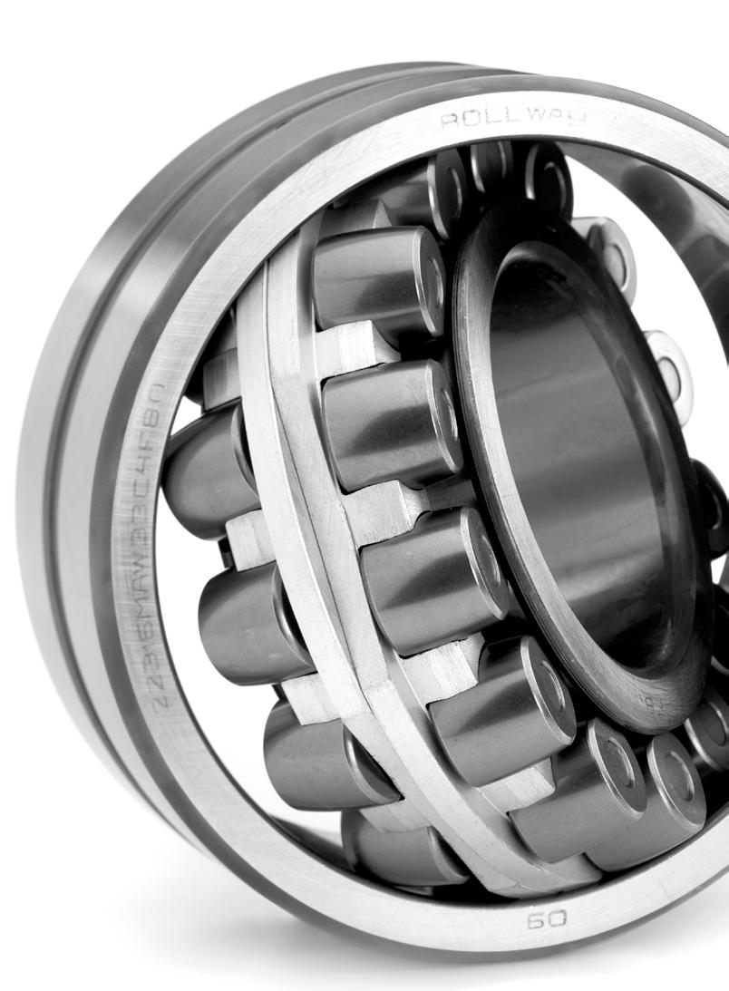
216
217 SPHERICAL ROLLER BEARINGS Dimensions in accordance with ISO Spherical roller bearings are designed to provide for heavy loads, shaft misalignment and deflection. They contain two symmetrical or asymmetrical rows of barrel-shaped rollers which align themselves in the outer race sphered track. They are therefore able to carry very heavy radial loads and axial loads in either direction. Roller guidance is achieved by the fixed flange for MB design, or floating flange of the inner race on design C, CA and CB. See technical section for further informantion Misalignment The table below give figures for permitted misalignment in the different bearing series. Bearings series Angular misalignment degrees
218 SPHERICAL ROLLER BEARINGS Roller guidance designs The sketches above show four types of roller guidance. C Rollers are assymetrical guided by sheet metal cage with floating center rib CA Rollers are assymetrical guided by brass cage whereas the cage is centered on the rollers MB Rollers are guided by 2 piece brass cage whereas the cage is centered on the inner ring MA Rollers are guided by 2 piece brass cage whereas the cage is centered on the outer ring Sherical roller bearings are manufactured with tapered bore-k(1:12) and K30 (1:30) with lubrication groove and 3 lubrication holes on the outside diameter W33 All Rollway sphericals have the W33 feature. Tolerances Spherical roller bearings with cylindrical and tapered bore are generally manufactured to PO presicion class. Radial clearance Spherical roller bearings with cylindrical and tapered bore are generally manufactured to normal (CN), C2, C3, C4 and C5 clearances. Heat treatment Spherical roller bearings with outside diameter D>240mm of all series given in this cataloge can be used to an operating temperature of +200 C. Small sized bearings operate normally at temperatures up to +120 C 216
219 Spherical roller bearings Bearing ISO dimensions Load ratings Speed limits Weight Dimensions Type Version d D B C Co Grease Oil rs e Y1 Y2 Y0 mm kn kn r/min r/min kg min C W ,18 1 0,35 1,90 2,90 1, CA W ,1 43, , ,35 1,92 2,86 1, C W ,28 1 0,36 1,90 2,80 1, CA W , , ,33 2,03 3,02 1, C W ,43 1,1 0,36 1,90 2,80 1, CA W , ,447 1,1 0,33 2,03 3,02 1, C W ,52 1,1 0,31 2,20 3,20 2, CA W , ,536 1,1 0,29 2,35 3,50 2, MB W ,571 1,1 0,31 2,20 3,20 2, C W ,71 1,5 0,26 2,60 3,90 2, C W ,96 1,5 0,40 2,60 2,50 1, MA F80 W ,05 1,5 0,40 1,70 2,50 1, MB W ,05 1,5 0,40 1,70 2,50 1, CA W ,03 1,5 0,39 1,75 2,61 1, C W ,95 1,5 0,26 2,60 3,90 2, MB W ,03 1,5 0,26 2,60 3,90 2, C W ,56 1,1 0,30 2,30 3,40 2, MB W , , CA W ,5 91, ,597 1,1 0,27 2,50 3,72 2, C W ,35 1,5 0,40 1,70 2,50 1, MB W ,36 1,5 0,40 1,70 2,50 1, MA F80 W ,36 1,5 0,40 1,70 2,50 1, CA W ,43 1,5 0,39 1,71 2,54 1, C W ,25 2 0,24 2,80 4,10 2,70 217
220 Spherical roller bearings Bearing ISO dimensions Load ratings Speed limits Weight Dimensions Type Version d D B C Co Grease Oil rs e Y1 Y2 Y0 mm kn kn r/min r/min kg min MB W ,33 2 0,27 2,50 3,70 2, MB W , ,771 1,1 0,26 2,60 3,80 2, C W ,61 1,1 0,26 2,60 3,90 2, CA W ,1 97, ,64 1,1 0,25 2,71 4,04 2, C W ,81 2 0,40 1,70 2,50 1, MB W ,85 2 0,40 1,70 2,50 1, MA F80 W ,91 2 0,40 1,70 2,50 2, CA W ,87 2 0,38 1,78 2,65 1, C W ,6 2 0,24 2,80 4,10 2, MB W ,72 2 0,26 2,50 3,80 2, C W ,89 1,5 0,24 2,70 4,10 2, MB W , , CA W ,849 1,5 0,26 2,64 3,93 2, C W ,32 2 0,40 1,70 2,50 1, MA F80 W ,44 2 0,40 1,70 2,50 1, MB W ,44 2 0,40 1,70 2,50 1, CA W ,43 2 0,37 1,80 2,69 1, C W ,9 2,1 0,24 2,90 4,30 2, CA W ,99 2,1 0,26 2,64 3,93 2, MB W ,8 140, ,39 1,5 0,27 2,50 3,70 2, C W ,16 1,5 0,27 2,50 3,70 2, CA W ,2 1,5 0,25 2,71 4,04 2, C W ,91 2,1 0,40 1,70 2,50 1, MA F80 W ,04 2,1 0,40 1,70 2,50 1,70 218
221 Bearing ISO dimensions Load ratings Speed limits Weight Dimensions Type Version d D B C Co Grease Oil rs e Y1 Y2 Y0 mm kn kn r/min r/min kg min MB W ,04 2,1 0,40 1,70 2,50 1, CA W ,01 2,1 0,37 1,80 2,69 1, C W ,45 2,1 0,24 2,80 4,20 2, CA W ,45 2,1 0,25 2,69 4,00 2, C W ,68 1,5 0,28 2,40 3,60 2, MB W ,87 1,5 0,28 2,40 3,60 2, CA W ,61 1,5 0,27 2,49 3,71 2, C W ,51 2,1 0,39 1,70 2,60 1, MA F80 W ,51 2,1 0,39 1,70 2,60 1, MB W ,71 2,1 0,39 1,70 2,60 1, CA W ,53 2,1 0,35 1,92 2,86 1, MB W ,12 2,1 0,26 2,60 4,00 2, CA W ,98 2,1 0,25 2,74 4,08 2, C W ,82 1,5 0,26 2,60 3,90 2, CA W ,68 1,5 0,24 2,83 4,21 2, MB W ,94 1,5 0,24 2,80 4,20 2, C W ,32 2,1 0,38 1,80 2,60 1, MA F80 W ,53 2,1 0,37 1,80 2,70 1, MB W ,53 2,1 0,37 1,80 2,70 1, CA W ,37 2,1 0,35 1,95 2,91 1, C W ,55 2,1 0,23 2,90 4,40 2, CA W ,63 2,1 0,24 2,84 4,23 2, MB W ,75 2,1 0,23 2,90 4,40 2, C W ,89 1,5 0,23 2,90 4,40 2,90 219
222 Spherical roller bearings Bearing ISO dimensions Load ratings Speed limits Weight Dimensions Type Version d D B C Co Grease Oil rs e Y1 Y2 Y0 mm kn kn r/min r/min kg min MB W ,72 1,5 0,24 2,80 4,10 2, CA W ,77 1,5 0,25 2,74 4,08 2, C W ,25 2,1 0,38 1,80 2,60 1, MA F80 W ,6 2,1 0,38 1,80 2,60 1, MB W ,26 2,1 0,38 1,80 2,60 1, CA W ,5 2,1 0,36 1,87 2,79 1, C W ,25 2,1 0,23 2,90 4,40 2, CA W ,29 2,1 0,24 2,84 4,23 2, MB W ,29 2,1 0,24 2,84 4,23 2, C W ,05 2 0,25 2,60 4,00 2, MB W ,14 2 0,24 2,80 4,10 2, CA W ,2 2 0,22 3,01 4,48 2, C W ,29 2,1 0,35 1,90 2,90 1, MA F80 W ,62 2,1 0,25 2,60 4,00 2, MB W ,2 2,1 0,25 2,60 4,00 2, MB W ,1 2,1 0,25 2,60 4,00 2, CA W ,54 2,1 0,36 1,87 2,79 1, MB W , ,78 3 0,22 3,00 4,50 2, C W ,55 2 0,26 2,60 3,90 2, MB W ,78 2 0,25 2,70 4,00 2, CA W ,73 2 0,23 2,95 4,40 2, C W ,5 3 0,37 1,80 2,70 1, MA F80 W ,44 3 0,37 1,80 2,70 1, MB W ,5 3 0,37 1,80 2,70 1,80 220
223 Bearing ISO dimensions Load ratings Speed limits Weight Dimensions Type Version d D B C Co Grease Oil rs e Y1 Y2 Y0 mm kn kn r/min r/min kg min CA W ,42 3 0,34 2,01 3,00 1, MBW ,86 3 0,25 2,70 4,00 2, C W ,25 2 0,27 2,50 3,80 2, MB W ,57 2 0,26 2,60 3,80 2, CA W ,47 2 0,23 2,90 4,31 2, C W ,6 3 0,36 1,90 2,80 1, MA F80 W ,8 3 0,37 1,80 2,70 1, MB W ,8 3 0,37 1,80 2,70 1, CA W ,87 3 0,34 1,98 2,94 1, C W , ,75 2 0,32 2,20 3,20 2, MB W , ,37 2 0,34 2,00 3,00 2, CA W , ,64 2 0,33 2,07 3,09 2, MB W ,15 3 0,22 3,10 4,60 3, CA W ,43 3 0,22 3,00 4,50 3, C W ,26 2,1 0,24 2,80 4,20 2, MB W ,1 2,1 0,26 2,60 3,80 2, CA W ,32 2,1 0,26 2,64 3,93 2, C W ,3 3 0,35 1,90 2,90 1, MA F80 W ,7 3 0,38 1,80 2,70 1, MB W ,2 3 0,38 1,80 2,70 1, CA W ,4 3 0,35 1,92 2,86 1, MB W ,8 3 0,22 3,10 4,70 3, CA W ,07 3 0,22 3,10 4,70 3, C W ,24 2,1 0,24 2,80 4,20 2,80 221
224 Spherical roller bearings Bearing ISO dimensions Load ratings Speed limits Weight Dimensions Type Version d D B C Co Grease Oil rs e Y1 Y2 Y0 mm kn kn r/min r/min kg min MB W ,85 2,1 0,27 2,50 3,70 2, CA W ,1 2,1 0,26 2,55 3,80 2, C W ,2 3 0,37 1,80 2,70 1, MA F80 W ,5 3 0,37 1,80 2,70 1, MB W ,5 3 0,37 1,80 2,70 1, CA W ,3 3 0,35 1,91 2,85 1, C W ,28 2,40 3,50 2, MB W ,5 2 0,31 2,20 3,20 2, CA W ,39 2 0,31 2,21 3,29 2, C W , ,34 2,1 0,33 2,00 3,00 2, MA W , ,7 2,1 0,33 2,00 3,00 2, MB W , ,8 2,1 0,33 2,00 3,00 2, CA W , ,81 2,1 0,33 2,03 3,02 1, CA W ,15 1,5 0,30 2,23 3,32 2, MB W ,21 3,20 4,80 3, C W ,45 2,1 0,25 2,70 4,00 2, MB W ,1 2,1 0,28 2,40 3,50 2, CA W ,69 2,1 0,26 2,55 3,80 2, C W ,37 1,80 2,70 1, MA F80 W ,7 3 0,37 1,80 2,70 1, MB W ,7 3 0,37 1,80 2,70 1, CA W ,3 3 0,35 1,91 2,85 1, MB W ,7 2 0,26 2,60 3,90 2, CA W ,79 2 0,25 2,67 3,97 2,61 222
225 Bearing ISO dimensions Load ratings Speed limits Weight Dimensions Type Version d D B C Co Grease Oil rs e Y1 Y2 Y0 mm kn kn r/min r/min kg min C W ,19 2 0,30 2,30 3,40 2, MB W ,55 2 0,30 2,30 3,30 2, CA W ,72 2 0,29 2,32 3,45 2, C W ,8 2, ,8 2,1 0,33 2,00 3,00 2, MB W , ,7 2,1 0,33 2,00 3,00 2, CA W , ,79 2,1 0,34 2,00 2,97 1, MB W ,85 2 0,39 1,70 2,60 1, CA W ,85 2 0,39 1,70 2,60 1, C W ,6 2,1 0,29 2,30 3,50 2, MB W ,3 2,1 0,29 2,30 3,50 2, CA W ,06 2,1 0,27 2,49 3,71 2, C W ,7 3 0,35 1,90 2,90 1, MA F80 W ,4 3 0,35 1,90 2,90 1, MB W ,36 1,80 2,70 1, CA W ,4 3 0,34 1,96 2,92 1, C W ,25 2 0,22 3,00 4,60 2, MB W ,2 2 0,24 2,80 4,20 2, CA W ,1 2 0,24 2,79 4,15 2, MB W ,8 2 0,31 2,20 3,30 2, CA W ,01 2 0,30 2,25 3,34 2, MB W ,1 0,37 1,80 2,70 1, CA W ,1 2,1 0,34 1,98 2,94 1, MB W ,1 2 0,32 2,10 3,10 2, CA W ,4 2 0,30 2,26 3,37 2,21 223
226 Spherical roller bearings Bearing ISO dimensions Load ratings Speed limits Weight Dimensions Type Version d D B C Co Grease Oil rs e Y1 Y2 Y0 mm kn kn r/min r/min kg min MB W ,2 2 0,40 1,70 2,50 1, CA W ,2 2 0,39 1,74 2,59 1, C W ,29 2,30 3,50 2, MB W ,2 3 0,29 2,30 3,40 2, CA W ,2 3 0,28 2,43 3,61 2, C W ,9 4 0,38 1,90 2,90 1, MA F80 W ,2 4 0,37 1,80 2,70 1, MB W ,5 4 0,37 1,80 2,70 1, MB W ,3 4 0,37 1,80 2,70 1, CA W ,5 4 0,35 1,95 2,90 1, C W ,59 2 0,23 2,90 4,40 2, MB W ,1 2 0,23 2,90 4,40 2, CA W ,02 2 0,25 2,71 4,04 2, MB W ,55 2 0,30 2,30 3,30 2, CA W ,75 2 0,28 2,40 3,58 2, MB W ,33 2,00 3,00 2, CA W ,3 3 0,34 1,99 2,96 1, MB W ,95 2 0,34 2,00 3,00 1, CA W ,16 2 0,31 2,15 3,20 2, MB W ,37 1,80 2,70 1, CA W ,1 2 0,35 1,94 2,88 1, C W ,4 3 0,26 2,60 3,90 2, MB W ,29 2,30 3,50 2, CA W ,3 3 0,27 2,49 3,71 2,43 224
227 Bearing ISO dimensions Load ratings Speed limits Weight Dimensions Type Version d D B C Co Grease Oil rs e Y1 Y2 Y0 mm kn kn r/min r/min kg min C W ,35 1,90 2,90 1, MA F80 W ,2 4 0,38 1,70 2,60 1, MB W ,5 4 0,38 1,70 2,60 1, CA W ,9 4 0,35 1,91 2,85 1, C W ,2 2 0,22 3,00 4,60 2, MB W ,55 2 0,22 3,00 4,60 2, CA W ,43 2 0,24 2,81 4,19 2, MB W ,5 2,1 3,00 2,30 3,30 2, CA W ,7 2,1 0,28 2,39 3,56 2, MB W ,5 3 0,37 1,80 2,70 1, CA W ,9 3 0,35 1,92 2,85 1, C W ,8 3 0,33 2,00 3,00 2, MA F80 W ,2 4 0,43 1,60 2,30 1, MB W ,45 2 0,32 2,10 3,10 2, CA W ,42 2 0,29 2,30 3,42 2, MB W ,2 2,1 0,37 1,80 2,70 1, CA W ,1 2,1 0,35 1,94 2,88 1, C W ,8 3 0,26 2,60 3,90 2, MB W ,29 2,30 3,50 2, CA W ,1 3 0,27 2,49 3,71 2, C W ,6 4 0,35 1,90 2,90 1, MA F80 W ,5 4 0,38 1,70 2,60 1, MB W ,5 4 0,38 1,70 2,60 1, CA W ,7 4 0,35 1,92 2,86 1,88 225
228 Spherical roller bearings Bearing ISO dimensions Load ratings Speed limits Weight Dimensions Type Version d D B C Co Grease Oil rs e Y1 Y2 Y0 mm kn kn r/min r/min kg min C W ,5 2,1 0,22 3,00 4,60 2, MB W ,95 2,1 0,22 3,00 4,60 2, CA W ,81 2,1 0,24 2,84 4,23 2, MB W ,3 2,1 0,32 2,10 3,20 2, CA W ,2 2,1 0,31 2,16 3,22 2, MB W ,5 3 0,38 1,80 2,70 1, CA W ,3 3 0,36 1,87 2,79 1, MB W ,5 2,1 0,33 2,10 3,10 2, CA W ,5 2,1 0,30 2,26 3,37 2, CA W ,5 2,1 0,40 1,70 2,50 1, MB W ,9 2,1 0,40 1,70 2,50 1, CA W ,2 2,1 0,37 1,83 2,72 1, C W ,9 3 0,26 2,60 3,90 2, MB W ,3 3 0,29 2,30 3,40 2, CA W ,8 3 0,28 2,43 3,61 2, MA F80 W ,5 4 0,37 1,80 2,70 1, MB W ,8 4 0,37 1,80 2,70 1, CA W ,9 4 0,35 1,91 2,85 1, C W ,4 2,1 0,22 3,00 4,60 2, MB W ,3 2,1 0,22 3,00 4,60 2, CA W ,56 2,1 0,24 2,84 4,23 2, MB W ,5 2,1 0,32 2,10 3,20 2, CA W ,8 2,1 0,31 2,16 3,22 2, CA W ,7 3 0,38 1,80 2,70 1,70 226
229 Bearing ISO dimensions Load ratings Speed limits Weight Dimensions Type Version d D B C Co Grease Oil rs e Y1 Y2 Y0 mm kn kn r/min r/min kg min MB W ,7 3 0,38 1,80 2,70 1, MB W ,3 2,1 0,32 2,10 3,10 2, CA W ,1 0,30 2,26 3,37 2, C W ,5 2,1 0,41 1,60 2,50 1, MB W ,8 2,1 0,41 1,60 2,50 1, CA W ,1 2,1 0,39 1,74 2,59 1, C W ,7 4 0,27 2,50 3,70 2, MB W ,9 4 0,30 2,30 3,40 2, CA W ,2 4 0,28 2,41 3,59 2, C W ,3 4 0,33 2,00 3,00 2, MA F80 W ,37 1,80 2,70 1, MB W ,2 4 0,37 1,80 2,70 1, CA W ,1 4 0,35 1,91 2,85 1, C W ,2 2,1 0,23 2,90 4,40 2, MB W ,4 2,1 0,23 2,90 4,40 2, CA W ,1 0,25 2,74 4,08 2, MB W ,3 2,1 0,31 2,20 3,20 2, CA W ,2 2,1 0,31 2,21 3,29 2, C W ,8 4 0,35 1,90 2,90 1, CA W ,8 4 0,35 1,90 2,90 1, MB W ,8 4 0,36 1,90 2,80 1, CA W ,4 4 0,34 1,99 2,96 1, MB W ,7 2,1 0,34 2,00 3,00 2, CA W ,6 2,1 0,32 2,12 3,15 2,07 227
230 Spherical roller bearings Bearing ISO dimensions Load ratings Speed limits Weight Dimensions Type Version d D B C Co Grease Oil rs e Y1 Y2 Y0 mm kn kn r/min r/min kg min CA W ,4 2,1 0,39 1,70 2,60 1, MB W ,4 2,1 0,37 1,80 2,70 1, C W ,1 4 0,26 2,60 3,90 2, MB W ,4 4 0,29 2,30 3,50 2, CA W ,27 2,51 3,74 2, MA F80 W ,5 4 0,37 1,80 2,70 1, MB W ,37 1,80 2,70 1, CA W ,4 4 0,35 1,92 2,86 1, C W ,7 2,1 0,24 2,80 4,20 2, MB W ,6 2,1 0,24 2,80 4,20 2, CA W ,3 2,1 0,24 2,76 4,11 2, C W ,2 3 0,30 2,30 3,40 2, MB W ,4 3 0,32 2,10 3,10 2, CA W ,32 2,13 3,17 2, MB W ,8 4 0,36 1,90 2,80 1, CA W ,5 4 0,35 1,94 2,88 1, MB W ,88 2,1 0,36 1,90 2,80 1, MB W ,2 2,1 0,36 1,90 2,80 1, CA W ,5 2,1 0,33 2,03 3,02 1, C W ,7 3 0,40 1,70 2,50 1, CA W ,56 3 0,40 1,70 2,50 1, MB W ,48 3 0,40 1,70 2,50 1, C W ,26 2,60 3,90 2, MB W ,7 4 0,29 2,30 3,40 2,30 228
231 Bearing ISO dimensions Load ratings Speed limits Weight Dimensions Type Version d D B C Co Grease Oil rs e Y1 Y2 Y0 mm kn kn r/min r/min kg min CA W ,3 4 0,27 2,49 3,71 2, MB W ,8 5 0,37 1,80 2,70 1, CA W ,7 5 0,35 1,94 2,88 1, MA F80 W ,36 1,85 2,75 1, C W ,4 2,1 0,23 2,90 4,40 4, MB W ,6 2,1 0,26 2,60 3,90 2, CA W ,2 2,1 0,24 2,76 4,11 2, MB W ,6 3 0,33 2,00 3,00 2, CA W ,9 3 0,32 2,12 3,15 2, MB W ,9 4 0,36 1,90 2,80 1, CA W ,33 2,03 3,03 1, MB W , ,06 2 0,18 3,81 5,67 3, MB W ,3 2,1 0,34 2,00 3,00 2, CA W ,8 2,1 0,31 2,18 3,24 2, CA W ,5 3 0,40 1,70 2,50 1, MB W ,8 3 0,41 1,70 2,50 1, CA W ,3 3 0,37 1,82 2,71 1, MB W , CA W ,2 4 0,27 2,47 3,67 2, C W ,6 4 0,29 2,30 3,40 2, MB W ,36 1,80 2,80 1, CA W ,2 5 0,35 1,95 2,90 1, C W ,5 2,1 0,24 2,80 4,20 2, MB W ,1 0,24 2,80 4,20 2,80 229
232 Spherical roller bearings Bearing ISO dimensions Load ratings Speed limits Weight Dimensions Type Version d D B C Co Grease Oil rs e Y1 Y2 Y0 mm kn kn r/min r/min kg min CA W ,3 2,1 0,24 2,76 4,11 2, MB W ,5 3 0,35 1,90 2,90 1, CA W ,1 3 0,32 2,09 3,11 2, MB W ,5 4 0,35 1,90 2,90 1, CA W ,8 4 0,36 1,90 2,83 1, MB W ,5 2,1 0,20 3,40 5,10 3, MB W ,6 2,1 0,35 1,90 2,90 1, CA W ,4 2,1 0,33 2,07 3,09 2, MB W ,07 3 0,40 1,70 2,50 1, CA W ,3 3 0,40 1,68 2,50 1, MB W ,29 2,30 3,40 2, CA W ,5 4 0,26 2,55 3,80 2, MB W ,8 5 0,36 1,80 2,80 1, CA W ,32 2,09 3,11 2, C W ,5 3 0,24 2,80 4,20 2, MB W ,5 3 0,24 2,80 4,20 2, CA W ,24 2,79 4,15 2, MB W ,5 4 0,30 2,30 3,40 2, CA W ,1 4 0,31 2,21 3,29 2, MB W ,5 4 0,35 1,90 2,90 1, CA W ,5 4 0,36 1,87 2,79 1, MB W ,3 2,1 0,18 3,70 5,60 3, MB W ,5 3 0,34 2,00 3,00 1, CA W ,5 3 0,32 2,09 3,11 2,04 230
233 Bearing ISO dimensions Load ratings Speed limits Weight Dimensions Type Version d D B C Co Grease Oil rs e Y1 Y2 Y0 mm kn kn r/min r/min kg min MB W ,4 4 0,41 1,60 2,50 1, MB W ,2 4 0,29 2,30 3,40 2, CA W ,7 4 0,28 2,45 3,64 2, CA W ,32 2,09 3,11 2, MBW ,31 2,20 3,30 2, CA W ,3 3 0,24 2,81 4,19 2, MBW ,2 3 0,23 2,90 4,40 2, MB W ,4 4 0,30 2,30 3,40 2, CA W ,3 4 0,32 2,13 3,17 2, MB W , MB W ,3 2,1 0,17 4,00 5,90 3, MB W ,2 4 0,32 2,10 3,10 2, CA W ,6 3 0,30 2,26 3,37 2, MB W , ,41 1,60 2,50 1, MB W ,7 5 0,29 2,30 3,40 2, CA W ,31 2,20 3,30 2, CA W ,83 4 0,23 2,90 4,40 2, MB W ,83 4 0,23 2,90 4,40 2, MB W , CA W ,7 4 0,31 2,2 3,3 2, MB W ,5 5 0,36 1,9 2,8 1, MB W ,6 2,1 0,19 3,60 5,30 3, MB W ,89 4 0,33 2,00 3,00 2, CA W ,33 2,07 3,09 2,03 231
234 Spherical roller bearings Bearing ISO dimensions Load ratings Speed limits Weight Dimensions Type Version d D B C Co Grease Oil rs e Y1 Y2 Y0 mm kn kn r/min r/min kg min MB W ,9 4 0,42 1,60 2,50 1, MB W ,5 5 0,28 2,40 3,60 2, CA W ,32 2,09 3,11 2, MB W ,24 2,79 4,15 2, CA W ,8 4 0,24 2,79 4,15 2, MB W ,3 5 0,30 2,30 3,40 2, CA W ,7 2,1 0,18 3,80 5,66 3, MB W ,8 2,1 0,18 3,70 5,60 3, MB W ,8 4 0,33 2,00 3,00 2, CA W ,40 1,70 2,50 1, MB W ,3 5 0,39 1,70 2,60 1, CA W ,26 2,60 3,90 2, MB W ,8 4 0,23 2,90 4,40 2, CA W ,4 4 0,23 2,90 4,40 2, CA W ,32 2,09 3,11 2, CA W ,35 1,90 2,90 1, CA W ,1 3 0,19 3,60 5,30 3, MB W ,23 3 0,20 3,40 3,40 3, MB W ,6 4 0,35 1,90 2,90 1, CA W ,32 2,09 3,11 2, CA W ,39 1,75 2,61 1, MB W ,1 5 0,40 1,70 2,50 1, CA W ,26 2,60 3,90 2, CA W ,7 4 0,23 2,90 4,40 2,80 232
235 Bearing ISO dimensions Load ratings Speed limits Weight Dimensions Type Version d D B C Co Grease Oil rs e Y1 Y2 Y0 mm kn kn r/min r/min kg min MB W ,8 4 0,23 2,90 4,40 2, CA W ,31 2,20 3,30 2, CA W ,35 1,90 2,90 1, CA W ,7 3 0,18 3,80 5,60 3, MB W ,92 3 0,19 3,50 5,30 3, MB W ,4 4 0,33 2,10 3,10 2, CA W ,31 2,20 3,30 2, CA W ,40 1,70 2,50 1, CA W ,24 2,80 4,20 2, MB W ,3 5 0,24 2,80 4,20 2, CA W ,31 2,20 3,30 2, CA W ,17 4,00 5,90 4, MB W ,98 3 0,18 3,70 5,60 3, CA W ,32 2,00 3,00 2, CA W ,40 1,70 2,50 1, CA W ,26 2,60 3,90 2, CA W ,22 5 0,23 2,90 4,40 2, CA W ,33 2,30 3,40 2, MB W ,33 2,30 3,40 2, CA W ,35 1,90 2,90 1, MB W ,22 3 0,17 4,10 6,00 4, CA W ,4 3 0,16 4,20 6,30 4, CA W ,33 2,00 3,00 2, CA W ,37 1,80 2,70 1,80 233
236 Spherical roller bearings Bearing ISO dimensions Load ratings Speed limits Weight Dimensions Type Version d D B C Co Grease Oil rs e Y1 Y2 Y0 mm kn kn r/min r/min kg min CA W ,22 3,00 4,60 2, CA W ,30 2,30 3,40 2, CA W ,35 1,90 2,90 1, CA W ,5 4 0,17 4,00 5,90 4, CA W ,30 2,30 3,40 2, CA W ,30 2,30 3,40 2, CA W ,23 2,90 4,40 2, CA W ,30 2,30 3,40 2, CA W ,28 2,40 3,60 2, CA W ,36 1,87 2,79 1, CA W ,35 1,90 2,90 1, CA W ,4 4 0,17 4,00 5,90 4, CA W ,6 4 0,16 4,20 6,30 4, CA W ,22 3,00 4,60 2, CA W ,30 2,30 3,40 2, CA W ,30 2,30 3,40 2, CA W ,38 1,80 2,60 1, CA W ,5 0,35 1,90 2,90 1, CA W ,17 4,00 5,90 4, CA W ,30 2,30 3,40 2, CA W ,30 2,30 3,40 2, CA W ,37 1,80 2,70 1, CA W ,5 0,35 1,90 2,90 1, CA W ,17 4,00 5,90 4,00 234
237 Bearing ISO dimensions Load ratings Speed limits Weight Dimensions Type Version d D B C Co Grease Oil rs e Y1 Y2 Y0 mm kn kn r/min r/min kg min CA W ,16 4,20 6,30 4, CA W ,5 0,30 2,30 3,40 2, CA W ,22 3,00 4,60 2, CA W ,29 2,35 3,50 2, CA W ,5 0,37 1,80 2,70 1, CA W ,4 3 0,13 5,36 7,98 5, CA W ,18 3,80 5,60 3, CA W ,21 3,20 4,80 3, CA W ,28 2,40 3,60 2, CA W ,5 0,37 1,80 2,70 1, CA W ,5 0,35 1,90 2,90 1,80 230/500 CA W ,21 3,20 4,80 3,20 238/500 CA W ,12 5,60 8,40 5,60 239/500 CA W ,17 4,00 5,90 4,00 240/500 CA W ,26 2,60 3,90 2,50 231/500 CA W ,5 0,30 2,30 3,40 2,20 241/500 CA W ,5 0,37 1,80 2,70 1,80 248/530 CA W ,15 4,50 6,70 4,50 230/530 CA W ,22 3,00 4,60 2,80 240/530 CA W ,29 2,30 3,50 2,40 231/530 CA W ,5 0,30 2,30 3,40 2,20 239/530 CA W ,17 4,00 5,90 4,00 241/530 CA W ,5 0,37 1,80 2,80 1,80 230/560 CA W ,22 3,14 4,67 3,07 235
238 Spherical roller bearings Bearing ISO dimensions Load ratings Speed limits Weight Dimensions Type Version d D B C Co Grease Oil rs e Y1 Y2 Y0 mm kn kn r/min r/min kg min 239/560 CA W ,16 4,20 6,30 4,00 240/560 CA W ,28 2,40 3,60 2,50 231/560 CA W ,5 0,30 2,30 3,40 2,20 232/560 CA W ,5 0,35 1,90 2,90 1,80 241/560 CA W ,5 0,37 1,80 2,80 1,80 239/600 CA W ,17 4,00 5,90 4,00 230/600 CA W ,22 3,00 4,60 2,80 240/600 CA W ,30 2,30 3,40 2,80 241/600 CA W ,5 0,36 1,90 2,82 1,85 230/630 CA W ,5 0,21 3,20 4,80 3,20 239/630 CA W ,17 4,00 5,90 4,00 240/630 CA W ,5 0,30 2,30 3,40 2,20 231/630 CA W ,5 0,30 2,30 3,40 2,20 241/630 CA W ,5 0,37 1,80 2,70 1,80 238/670 CA W ,11 6,10 9,10 6,30 248/670 CA W ,16 4,20 6,30 4,00 240/670 CA W ,5 0,28 2,40 3,60 2,50 231/670 CA W ,5 0,30 2,30 3,40 2,20 241/670 CA W ,5 0,36 1,87 2,79 1,83 232/670 CA W ,35 1,90 2,90 1,80 249/670 CA W ,22 3,00 4,50 2,70 240/710 CA W ,5 0,27 2,50 3,70 2,50 231/710 CA W ,8 0,28 2,40 3,60 2,50 232/710 CA W ,35 1,90 2,90 1,80 236
239 Bearing ISO dimensions Load ratings Speed limits Weight Dimensions Type Version d D B C Co Grease Oil rs e Y1 Y2 Y0 mm kn kn r/min r/min kg min 239/710 CA W ,17 4,00 5,90 4,00 232/750 CA W ,36 1,87 2,79 1,83 238/750 CA W ,11 6,10 9,10 6,30 239/750 CA W ,16 4,20 6,30 4,00 249/750 CA W ,22 3,00 4,60 2,80 230/750 CA W ,5 0,21 3,20 4,80 3,20 240/750 CA W ,5 0,28 2,40 3,60 2,50 231/750 CA W ,5 0,28 2,40 3,60 2,50 241/750 CA W ,5 0,35 1,90 2,90 1,80 248/800 CA W ,15 4,50 6,70 4,50 239/800 CA W ,16 4,20 6,30 4,00 249/800 CA W ,21 3,20 4,80 3,20 230/800 CA W ,5 0,20 3,40 5,00 3,20 231/800 CA W ,5 0,28 2,40 3,60 2,50 238/850 CA W ,11 6,10 9,10 6,30 239/850 CA W ,16 4,20 6,30 4,00 240/850 CA W ,5 0,27 2,50 3,70 2,50 249/850 CA W ,22 3,00 4,60 2,80 231/850 CA W ,28 2,40 3,60 2,50 241/850 CA W ,35 1,80 290/890 MB W26 450,85 571, ,51 2,5 0,25 5,40 8,00 5,30 248/900 CA W ,14 4,80 7,20 4,50 230/900 CA W ,5 0,20 3,40 5,00 3,20 240/900 CA W ,5 0,26 2,60 3,90 2,50 237

240 Spherical roller bearings Bearing ISO dimensions Load ratings Speed limits Weight Dimensions Type Version d D B C Co Grease Oil rs e Y1 Y2 Y0 mm kn kn r/min r/min kg min 241/900 CA W ,35 1,90 2,90 1,91 239/950 CA W ,5 0,15 4,50 6,70 4,50 249/950 CA W ,5 0,21 3,20 4,80 3,20 240/950 CA W ,5 0,27 2,50 3,70 2,50 241/950 CA W ,5 0,35 1,90 2,90 1,80 249/1000 CA W ,5 0,21 3,20 4,80 3,20 231/1000 CA W ,28 2,40 3,50 2,50 241/1000 CA W ,35 1,90 2,90 1,80 238/1060 CA W ,11 6,10 9,10 6,30 248/1060 CA W ,14 4,80 7,20 4,50 249/1060 CA W ,5 0,21 3,20 4,80 3,20 230/1060 CA W ,5 0,19 3,60 5,30 3,60 240/1060 CA W ,5 0,26 2,60 3,90 2,50 248/1120 CA W ,15 4,50 6,70 4,50 240/1120 CA W ,5 0,26 2,60 3,90 2,50 248/1180 CA W ,14 4,80 7,20 4,50 230/1250 CA W ,5 0,19 3,60 5,30 3,60 248/1320 CA W ,15 4,50 6,70 4,50 249/1320 CA W ,5 0,21 3,20 4,80 3,20 248/1500 CA W ,5 0,15 4,50 6,70 4,50 248/1800 CA W ,5 0,15 4,50 6,70 4,50 238
241 239
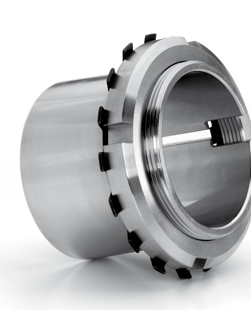
242
243 ADAPTER SLEEVES Dimensions in accordance with ISO 113/ Adapter sleeves are used to locate tapered bore bearings on cylindrical shafts. This allows less accurate machining of the shafts and ease of location. Adapter sleeves are available in metric or inch bore sizes - the external taper is 1:12. See page 75 for tolerances. 241
244 Adapter sleeve Bearing ISO dimensions Weight Type Version d1 d d3 B1 B2 G mm kn kn kg Locking nut Locking device H M 20x1 0,041 KM 4 MB 4 H M 20x1 0,049 KM 4 MB 4 H M 20x1 0,045 KM 4 MB 4 H M 25x1,5 0,070 KM 5 MB 5 H M 25x1,5 0,087 KM 5 MB 5 H M 25x1,5 0,075 KM 5 MB 5 H M 30x1,5 0,099 KM 6 MB 6 H M 30x1,5 0,126 KM 6 MB 6 H M 30x1,5 0,109 KM 6 MB 6 H M 35x1,5 0,125 KM 7 MB 7 H M 35x1,5 0,165 KM 7 MB 7 H M 35x1,5 0,142 KM 7 MB 7 H M 40x1,5 0,174 KM 8 MB 8 H M 40x1,5 0,224 KM 8 MB 8 H M 40x1,5 0,189 KM 8 MB 8 HE , M 40x1,5 0,220 KM 8 MB 8 H M 45x1,5 0,227 KM 9 MB 9 H M 45x1,5 0,280 KM 9 MB 9 H M 45x1,5 0,248 KM 9 MB 9 H M 50x1,5 0,274 KM 10 MB 10 H M 50x1,5 0,362 KM 10 MB 10 H M 50x1,5 0,303 KM 10 MB 10 H ,5 M 55x2 0,308 KM 11 MB 11 H ,5 M 55x2 0,420 KM 11 MB
245 Bearing ISO dimensions Weight Type Version d1 d d3 B1 B2 G mm kn kn kg Locking nut Locking device H ,5 M 55x2 0,345 KM 11 MB 11 H M 60x2 0,346 KM 12 MB 12 H M 60x2 0,481 KM 12 MB 12 H M 60x2 0,394 KM 12 MB 12 H M 65x2 0,401 KM 13 MB 13 H M 70x2 0,593 KM 14 MB 14 H M 65x2 0,557 KM 13 MB 13 H M 70x2 0,897 KM 14 MB 14 H M 65x2 0,458 KM 13 MB 13 H M 70x2 0,723 KM 14 MB 14 H M 75x2 0,707 KM 15 MB 15 H M 75x2 1,050 KM 15 MB 15 H M 75x2 0,831 KM 15 MB 15 H M 80x2 0,882 KM 16 MB 16 H M 80x2 1,280 KM 16 MB 16 H M 80x2 1,030 KM 16 MB 16 H M 85x2 1,020 KM 17 MB 17 H M 85x2 1,450 KM 17 MB 17 H M 85x2 1,180 KM 17 MB 17 H M 90x2 1,190 KM 18 MB 18 H M 90x2 1,690 KM 18 MB 18 H M 90x2 1,370 KM 18 MB 18 H M 95x2 1,370 KM 19 MB 19 H M 95x2 1,920 KM 19 MB
246 Adapter sleeve Bearing ISO dimensions Weight Type Version d1 d d3 B1 B2 G mm kn kn kg Locking nut Locking device H M 95x2 1,560 KM 19 MB 19 H M 100x2 1,490 KM 20 MB 20 H M 100x2 2,150 KM 20 MB 20 H M 100x2 1,800 KM 20 MB 20 H M 100x2 1,690 KM 20 MB 20 H M 105x2 1,720 KM 21 MB 21 H M 105x2 1,950 KM 21 MB 21 H M 110x2 1,930 KM 22 MB 22 H M 110x2 2,740 KM 22 MB 22 H M 110x2 2,250 KM 22 MB 22 H M 110x2 2,180 KM 22 MB 22 H M 120x2 3,190 KM 24 MB 24 H M 120x2 1,930 KML 24 MBL 24 H M 120x2 2,640 KM 24 MB 24 H M 130x2 4,600 KM 26 MB 26 H M 130x2 2,850 KML 26 MBL 26 H M 130x2 3,660 KM 26 MB 26 H M 140x2 5,550 KM 28 MB 28 H M 140x2 3,160 KML 28 MBL 28 H M 140x2 4,340 KM 28 MB 28 H M 150x2 6,630 KM 30 MB 30 H M 150x2 3,890 KML 30 MBL 30 H M 150x2 5,520 KM 30 MB 30 H M 160x3 9,140 KM 32 MB
247 Bearing ISO dimensions Weight Type Version d1 d d3 B1 B2 G mm kn kn kg Locking nut Locking device H ,5 M 160x3 5,210 KML 32 MBL 32 H M 160x3 7,670 KM 32 MB 32 H M 170x3 10,200 KM 34 MB 34 H ,5 M 170x3 5,990 KML 34 MBL 34 H M 170x3 8,380 KM 34 MB 34 H M 180x3 11,300 KM 36 MB 36 H 2336 OH Tr180x3 11,000 KM36 MB36 H ,5 M 180x3 6,830 KML 36 MBL 36 H 3036 OH ,5 Tr180x3 6,700 KML36 MBL36 H M 180x3 9,500 KM 36 MB 36 H 3136 OH M180X3 9,150 KM36 MB36 H ,5 M180x3 5,700 KML36 MBL36 H M 190x3 12,600 KM 38 MB 38 H 2338 OH Tr190x3 12,000 KM38 MB38 H ,5 M 190x3 7,450 KML 38 MBL 38 H 3038 OH ,5 Tr190x3 7,250 KML38 MBL38 H M 190x3 10,800 KM 38 MB 38 H 3138 OH M190X3 10,500 KM38 MB38 H ,5 M190x3 6,190 KML38 MBL38 H M 200x3 13,900 KM 40 MB 40 H 2340 OH Tr200x3 13,500 KM40 MB40 H ,5 M 200x3 9,190 KML 40 MBL 40 H 3040 OH ,5 Tr200x3 8,900 KML40 MBL40 H M 200x3 12,100 KM 40 MB
248 Adapter sleeve Bearing ISO dimensions Weight Type Version d1 d d3 B1 B2 G mm kn kn kg Locking nut Locking device H 3140 OH M200X3 12,000 KM40 MB40 H ,5 M200x3 7,890 KML40 MBL40 H Tr220x4 17,000 HM 44 T MB 44 H 2344 OH Tr220x4 17,000 HM44T MB44 H Tr220x4 10,300 HM3044 MS3044 H 3044 OH Tr220x4 9,900 HM3044 MS3044 H Tr220x4 15,000 HM44T MB44 H 3144 OH Tr200x3 15,000 HM44T MB44 H Tr220x4 8,160 HM3044 MS3044 H Tr 240x4 20,000 HM 48 T MB 48 H 2348 OH Tr240x4 19,000 HM48T MB48 H Tr240x4 13,200 HM3048 MS3048 H 3048 OH Tr240x4 12,000 HM3048 MS H Tr240x4 17,600 HM48T MB48 H 3148 OH Tr240x4 16,500 HM48T MB48 H Tr240x4 11,000 HM3048 MS3048 H Tr 260x4 24,500 HM 52 T MB 52 H 2352 OH Tr260x4 23,000 HM52T MB52 H Tr260x4 13,500 HM3052 MS H Tr260x4 15,300 HM3052 MS3052 H 3052 OH Tr260x4 13,500 HM3052 MS H Tr260x4 22,300 HM52T MB52 H 3152 OH Tr260x4 21,000 HM52T MB52 H Tr260x4 12,800 HM3052 MS
249 Bearing ISO dimensions Weight Type Version d1 d d3 B1 B2 G mm kn kn kg Locking nut Locking device H Tr 280x4 28,400 HM 56 T MB 56 H 2356 OH Tr280x4 27,000 HM56T MB56 H Tr280x4 17,700 HM3056 MS3056 H 3056 OH Tr280x4 16,000 HM3056 MS3056 H Tr280x4 25,100 HM56T MB56 H 3156 OH Tr280x4 19,300 HM3056 MS3056 H Tr280x4 15,300 HM3056 MS3056 H Tr300x4 20,500 HM3060 MS3060 H Tr300x4 22,800 HM3060 MS3060 H 3060 OH Tr300x4 20,500 HM3060 MS3060 H Tr300x4 30,200 HM3160 MS3160 H 3160 OH Tr300x4 29,000 HM3160 MS3160 H Tr300x4 34,100 HM3160 MS3160 H 3260 OH Tr300x4 32,000 HM3160 MS3160 H Tr300x4 20,000 HM3060 MS3060 H Tr320x5 24,600 HM3064 MS3064 H 3064 OH Tr320x5 22,000 HM3064 MS H Tr320x5 34,900 HM3164 MS3164 H 3164 OH Tr320X5 32,000 HM3164 MS3164 H Tr320x5 39,300 HM3164 MS3164 H 3264 OH Tr320x5 35,000 HM3164 MS3164 H Tr320x5 21,500 HM3064 MS3064 H Tr340x5 28,700 HM3068 MS3068 H 3068 OH Tr340x5 27,000 HM3068 MS
250 Adapter sleeve Bearing ISO dimensions Weight Type Version d1 d d3 B1 B2 G mm kn kn kg Locking nut Locking device H Tr340x5 50,000 HM3168 MS3168 H 3168 OH Tr340X5 50,000 HM3168 MS H Tr340x5 54,600 HM3168 MS3168 H 3268 OH Tr340x5 51,500 HM3168 MS H Tr340x5 24,500 HM3068 MS3068 H Tr360x5 30,500 HM3072 MS3072 H 3072 OH Tr360x5 29,000 HM3072 MS3072 H Tr360X5 56,000 HM3172 MS3172 H 3172 OH Tr360X5 56,000 HM3172 MS H Tr360x5 60,600 HM3172 MS3172 H 3272 OH Tr360x5 60,500 HM3172 MS H Tr360x5 25,200 HM3072 MS3072 H Tr380X5 35,800 HM3076 MS3076 H 3076 OH Tr380X5 35,500 HM3076 MS H Tr380X5 61,700 HM3176 MS3176 H 3176 OH Tr380X5 61,500 HM3176 MS3176 H Tr380X5 69,600 HM3176 MS3176 H 3276 OH Tr380X5 69,500 HM3176 MS3176 H Tr380x5 31,500 HM3076 MS3076 H Tr400x5 41,300 HM3080 MS3080 H 3080 OH Tr400x5 40,000 HM3080 MS H Tr400x5 73,000 HM3180 MS3180 H 3180 OH Tr400x5 73,000 HM3180 MS H Tr400x5 81,000 HM3180 MS
251 Bearing ISO dimensions Weight Type Version d1 d d3 B1 B2 G mm kn kn kg Locking nut Locking device H 3280 OH Tr400x5 87,000 HM3180 MS H Tr400x5 35,000 HM3080 MS3080 H Tr420X5 43,700 HM3084 MS3084 H 3084 OH Tr420X5 47,000 HM3084 MS3084 H Tr420X5 84,200 HM3184 MS3184 H 3184 OH Tr420X5 80,000 HM3184 MS H Tr420X5 96,000 HM3184 MS3184 H 3284 OH Tr420X5 96,000 HM3184 MS H Tr420X5 36,600 HM3084 MS3084 H Tr440X5 65,200 HM3088 MS3088 H 3088 OH Tr440X5 65,000 HM3088 MS H Tr440X5 104,000 HM3188 MS3188 H 3188 OH Tr440X5 95,000 HM3188 MS H Tr440X5 118,000 HM3188 MS3188 H 3288 OH Tr440X5 117,000 HM3188 MS H Tr440x5 58,000 HM3088 MS3088 H Tr460X5 71,000 HM3092 MS3092 H 3092 OH Tr460X5 71,000 HM3092 MS H Tr460X5 116,000 HM3192 MS3192 H 3192 OH Tr460X5 119,000 HM3192 MS H Tr460X5 134,000 HM3192 MS3192 H 3292 OH Tr460X5 134,000 HM3192 MS H Tr460x5 60,000 HM3092 MS3092 H Tr480X5 75,000 HM3096 MS30/96 249
252 Adapter sleeve Bearing ISO dimensions Weight Type Version d1 d d3 B1 B2 G mm kn kn kg Locking nut Locking device H 3096 OH Tr480X5 75,000 HM3096 MS30/ H Tr480X5 135,000 HM3196 MS3196 H 3196 OH Tr480X5 135,000 HM3196 MS3196 H Tr480X5 153,000 HM3196 MS3196 H 3296 OH Tr480X5 153,000 HM3196 MS3196 H Tr480x5 66,000 HM3096 MS30/96 H 30/ Tr500x5 82,000 HM30/500 MS30/500 H 30/500 OH Tr500x5 82,000 HM30/500 MS30/ H 31/ Tr500x5 145,000 HM31/500 MS31/500 H 31/500 OH Tr500x5 145,000 HM31/500 MS31/500 H 32/ Tr500x5 166,000 HM31/500 MS31/500 H 32/500 OH Tr500x5 170,000 HM31/500 MS31/500 H 39/ Tr500x5 74,300 HM30/500 MS30/500 H 30/ Tr530x6 105,000 HM30/530 MS30/530 H 30/530 OH Tr530x6 105,000 HM30/530 MS30/ H 31/ Tr530x6 161,000 HM31/530 MS31/530 H 32/ Tr530x6 192,000 HM31/530 MS31/530 H 39/ Tr530x6 87,900 HM30/530 MS30/530 H 39/530 OH Tr530x6 87,900 HM30/530 MS30/ H 30/ Tr560x6 112,000 HM30/560 MS30/560 H 30/560 OH Tr560x6 112,000 HM30/560 MS30/560 H 31/ Tr560x6 185,000 HM31/560 MS31/560 H 32/ Tr560x6 219,000 HM31/560 MS31/560 H 39/ Tr560x6 95,000 HM30/560 MS30/
253 Bearing ISO dimensions Weight Type Version d1 d d3 B1 B2 G mm kn kn kg Locking nut Locking device H 39/560 OH Tr560x6 95,000 HM30/560 MS30/560 H 30/ Tr600x6 147,000 HM30/600 MS30/600 H 30/600 OH Tr600x6 147,000 HM30/600 MS30/ H 31/ Tr600x6 234,000 HM31/600 MS31/600 H 32/ Tr600x6 278,000 HM31/600 MS31/600 H 39/ Tr600x6 127,000 HM30/600 MS30/600 H 39/600 OH Tr600x6 127,000 HM30/600 MS30/ H 30/ Tr630x6 138,000 HM30/630 MS30/630 H 30/630 OH Tr630x6 138,000 HM30/630 MS30/630 H 31/ Tr630x6 254,000 HM31/630 MS31/630 H 32/ Tr630x6 300,000 HM31/630 MS31/630 H 39/ Tr630x6 120,000 HM30/630 MS30/630 H 39/630 OH Tr630x6 124,000 HM30/630 MS30/630 H 30/ Tr670x6 191,000 HM30/670 MS30/670 H 30/670 OH Tr670x6 190,000 HM30/670 MS30/670 H 31/ Tr670x6 340,000 HM31/670 MS31/670 H 32/ Tr670x6 401,000 HM31/670 MS31/670 H 39/ Tr670x6 163,000 HM30/670 MS30/670 H 39/670 OH Tr670x6 162,000 HM30/670 MS30/670 H 30/ Tr710x7 223,000 HM30/710 MS30/710 H 30/710 OH Tr710x7 228,000 HM30/710 MS30/710 H 31/ Tr710x7 378,000 HM31/710 MS31/710 H 32/ Tr710x7 444,000 HM31/710 MS31/710 H 39/ Tr710x7 196,000 HM30/710 MS30/

254 Adapter sleeve Bearing ISO dimensions Weight Type Version d1 d d3 B1 B2 G mm kn kn kg Locking nut Locking device H 39/710 OH Tr710x7 183,000 HM30/710 MS30/710 H 30/ Tr750x7 246,000 HM30/750 MS30/750 H 31/ Tr750x7 451,000 HM31/750 MS31/750 H 32/ Tr750x7 507,000 HM31/750 MS31/750 H 39/ Tr750x7 211,000 HM30/750 MS30/750 H 30/ Tr800x7 300,000 HM30/800 MS30/800 H 31/ Tr800x7 515,000 HM31/800 MS31/800 H 32/ Tr800x7 610,000 HM31/800 MS31/800 H 39/ Tr800x7 259,000 HM30/800 MS30/
255 Withdrawal Sleeve Withdrawal Sleeve ISO dimensions Weight Type Version d1 d B1 B2 G G1 mm kg Dismounting nut Hydraulic nut AH M45x1,5 7 0,130 KM9 HMV9E AH M45x1,5 6 0,090 KM9 HMV9E AH M50x1,5 7 0,160 KM10 HMV10E AH M50x1,5 6 0,110 KM10 HMV10E AH M60x2 8 0,240 KM12 HMV12E AH M60x20 7 0,160 KM12 HMV12E AH M65x2 9 0,290 KM13 HMV13E AH M65x2 7 0,190 KM13 HMV13E AH M70x2 10 0,340 KM14 HMV14E AH M70x2 8 0,220 KM14 HMV14E AH M75x2 12 0,400 KM15 HMV15E AH M75x2 8 0,250 KM15 HMV15E AH M85x2 10 0,530 KM17 HMV17E AH M80x2 8 0,280 KM16 HMV16E AH M90x2 12 0,610 KM18 HMV18E AH M85x2 8 0,310 KM17 HMV17E AH M95x2 12 0,670 KM19 HMV19E AH M90x2 8 0,370 KM18 HMV18E AH M100x2 13 0,750 KM20 HMV20E AH M100x2 9 0,480 KM20 HMV20E AH M105x2 14 0,850 KM21 HMV21E AH M105x2 9 0,520 KM21 HMV21E AH M110x2 15 0,980 KM22 HMV22E AH M110x2 10 0,590 KM22 HMV22E 253
256 Withdrawal Sleeve Withdrawal Sleeve ISO dimensions Weight Type Version d1 d B1 B2 G G1 mm kg Dismounting nut Hydraulic nut AH M120x2 15 1,230 KM24 HMV24E AH M115x2 10 0,660 KM23 HMV23E AH M130x2 16 2,110 KM26 HMV26E AH M125x2 11 1,280 KM25 HMV25E AH M130x2 12 1,260 KM26 HMV26E AH M115x2 13 0,710 KM23 HMV23E AH M140x2 17 2,470 KM28 HMV28E AH M130x2 13 1,150 KM26 HMV26E AH M140x2 12 1,670 KM28 HMV28E AH M125x2 13 0,700 KM25 HMV25E AH M130x2 13 1,000 KM26 HMV26E AH M150x2 19 3,020 KM30 HMV30E AH M140x2 14 1,410 KM28 HMV28E AH M150x2 12 1,870 KM30 HMV30E AH M135x2 14 0,880 KM27 HMV27E AH M140x2 14 1,150 KM28 HMV28E AH M160x3 20 3,600 KM32 HMV32E AH M150x2 14 1,550 KM30 HMV30E AH M160x3 14 2,210 KM32 HMV32E AH M145x2 14 0,950 KM29 HMV29E AH M150x2 14 1,300 KM30 HMV30E AH M170x3 24 4,220 KM34 HMV34E AH M160x3 15 1,760 KM32 HMV32E AH M170x3 15 2,700 KM34 HMV34E 254
257 Withdrawal Sleeve ISO dimensions Weight Type Version d1 d B1 B2 G G1 mm Dismounting nut Hydraulic nut AH M155x3 15 1,050 KM31 HMV31E AH M160x3 15 1,550 KM32 HMV32E AH M180x3 24 4,720 KM36 HMV36E AH M170x3 15 2,300 KM34 HMV34E AH M170x3 15 3,000 KM34 HMV34E AH M170x3 16 2,060 KM34 HMV34E AH M180x3 16 3,210 KM36 HMV36E AH M180x3 20 4,080 KM36 HMV36E AH M190x3 24 5,250 KM38 HMV38E AH M180x3 16 2,700 KM36 HMV36E AH M180x3 16 3,250 KM36 HMV36E AH M180x3 17 2,430 KM36 HMV36E AH M190x3 16 3,400 KM38 HMV38E AH M200x3 19 4,220 KM40 HMV40E AH M190x3 24 4,800 KM38 HMV38E AH M200x3 17 3,730 KM40 HMV40E AH M200x3 26 5,830 KM40 HMV40E AH 2336 OH M200x3 26 6,050 KM40 HMV40E AH M190x3 16 3,200 KM38 HMV38E AH M190x3 16 3,750 KM38 HMV38E AH M190x3 17 2,810 KM38 HMV38E AH M190X3 17 2,800 KM38 HMV38E AH 3036 OH M190X3 17 2,800 KM38 HMV38E AH 3136 OH M200x3 19 3,900 KM38 HMV38E kg 255
258 Withdrawal Sleeve Withdrawal Sleeve ISO dimensions Weight Type Version d1 d B1 B2 G G1 mm kg Dismounting nut Hydraulic nut AH M200x3 24 5,320 KM40 HMV40E AH 3236 OH M200x3 24 4,850 KM38 HMV38E AH TR210x4 18 4,250 HM42T HMV42E AH TR210x4 26 6,630 HM42T HMV42E AH 2338 OH TR210x4 26 6,700 HM42T HMV42E AH M200x3 18 3,550 KM40 HMV40E AH M200x3 18 4,450 KM40 HMV40E AH TR205x4 18 3,320 HML41T HMV41E AH M205X3 18 3,300 KM40 HMV40E AH 3038 OH M205x3 18 3,300 KM40 HMV40E AH TR210x4 20 4,890 HM42T HMV42E AH 3138 OH TR210x4 20 4,500 KM40 HMV40E AH TR210x4 25 5,900 KM42T HMV42E AH 3238 OH TR210x4 25 5,900 KM40 HMV40E AH TR220x4 19 4,680 HM44T HMV44E AH TR220x4 30 7,540 HM44T HMV44E AH 2340 OH TR220x4 30 7,600 HM44T HMV44E AH TR210x4 18 4,000 HM42T HMV42E AH OH TR210x4 18 5,050 HM42T HMV42E AH TR215x4 19 3,800 HML43T HMV43E AH 3040 OH TR215x4 19 3,700 HM42T HMV42E AH TR220x4 21 5,490 HM44T HMV44E AH 3140 OH TR220x4 21 5,650 HM3044 HMV44E AH TR220x4 25 6,680 HM44T HMV44E 256
259 Withdrawal Sleeve ISO dimensions Weight Type Version d1 d B1 B2 G G1 mm Dismounting nut Hydraulic nut AH 3240 OH TR220x4 25 6,600 HM3044 HMV44E AH TR240x4 20 9,100 HM48T HMV48E AH TR240x ,500 HM48T HMV48E AH 2344 OH TR240x ,500 HM48T HMV48E AH OH TR230x ,500 HM46T HMV46E AH TR235x4 20 7,400 HML47T HMV47E AH TR235X4 20 7,300 HM46T HMV46E AH 3044 OH TR235X4 20 7,300 HM46T HMV46E AH TR240x ,400 HM48T HMV48E AH 3144 OH TR240x4 23 9,300 HM3048 HMV48E AH TR260x ,100 HM52T HMV52E AH 2248 OH TR260x ,500 HM3052 HMV52E AH TR260x ,500 HM52T HMV52E AH 2348 OH TR260x ,000 HM52T HMV52E AH TR260x4 21 8,750 HM52T HMV52E AH TR260x4 21 7,950 HM3052 HMV52E AH 3048 OH TR260x4 21 7,950 HM3052 HMV52E AH TR260x ,000 HM52T HMV52E AH 3148 OH TR260x ,000 HM3052 HMV52E AH TR290x ,000 HM58T HMV58E AH 2252 OH TR290x ,500 HM58T HMV58E AH TR290x ,600 HM58T HMV58E AH 2352 OH TR290x ,500 HM58T HMV58E AH TR280x ,700 HM56T HMV56E kg 257
260 Withdrawal Sleeve Withdrawal Sleeve ISO dimensions Weight Type Version d1 d B1 B2 G G1 mm kg Dismounting nut Hydraulic nut AH TR280x4 23 9,600 HM3056 HMV56E AH 3052 H TR280x4 23 9,600 HM3056 HMV56E AH 3052 OH TR280x4 23 9,600 HM3056 HMV56E AH TR290x ,200 HM58T HMV58E AH 3152 OH TR290x ,500 HM3056 HMV56E AH TR310x ,200 HM62T HMV62E AH 2256 OH TR300x ,000 HM3160 HMV60E AH TR310x ,100 HM3160 HMV60E AH 2356 OH TR310x ,500 HM62T HMV62E AH OH TR300x ,3 HM 60 T HMV 60 AH TR300x ,000 HM3060 HMV60E AH 3056 OH TR300x ,000 HM3060 HMV60E AH TR310x ,500 HM62T HMV62E AH 3156 OH TR310x ,000 HM3160 HMV60E AH TR330X ,100 HM66T HMV66E AH 2260 OH TR330X ,000 HM3164 HMV64E AH TR320x ,400 HM3064 HMV64E AH TR320X ,000 HM3064 HMV64E AH 3060 OH TR320X ,000 HM3064 HMV64E AH TR330X ,800 HM66T HMV66E AH 3160 OH TR330X ,500 HM3164 HMV64E AH TR330X ,000 HM66T HMV66E AH 3260 OH TR330X ,500 HM3164 HMV64E AH TR350X ,200 HM70T HMV70E 258
261 Withdrawal Sleeve ISO dimensions Weight Type Version d1 d B1 B2 G G1 mm Dismounting nut Hydraulic nut AH 2264 OH TR350X ,000 HM3168 HMV68E AH TR345x ,000 HML69T HMV69E AH TR345X ,000 HM3068 HMV68E AH 3064 OH TR345X ,000 HM3068 HMV68E AH TR350X ,500 HM70T HMV70E AH 3164 OH TR350X ,500 HM3168 HMV68E AH TR350X ,600 HM70T HMV70E AH 3264 OH TR350X ,500 HM3168 HMV68E AH TR365x ,500 HML73T HMV73E AH TR365X ,000 HM3072 HMV72E AH 3068 OH TR365X ,000 HM3072 HMV72E AH TR370X ,000 HM74T HMV74E AH 3168 OH TR370X ,500 HM3172 HMV72E AH TR370X ,400 HM74T HMV74E AH 3268 OH TR370X ,000 HM3172 HMV72E AH OH TR360x ,100 HM72T HMV72 AH TR385x ,000 HML77T HMV77E AH TR385X ,000 HM3076 HMV76E AH 3072 OH TR385X ,000 HM3076 HMV76E AH TR400X ,500 HM3180 HMV80E AH 3172 OH TR400X ,500 HM3176 HMV76E AH TR400X ,500 HM3180 HMV80E AH 3272 OH TR380X ,500 HM3176 HMV76E AH OH TR380X ,800 HM3176 HMV76E kg 259
262 Withdrawal Sleeve Withdrawal Sleeve ISO dimensions Weight Type Version d1 d B1 B2 G G1 mm kg Dismounting nut Hydraulic nut AH TR410x ,200 HML82T HMV82E AH TR410X ,500 HM3080 HMV80E AH 3076 OH TR410X ,500 HM3080 HMV80E AH TR420X ,700 HM3184 HMV84E AH 3176 OH TR420X ,000 HM3180 HMV80E AH TR420X ,600 HM3184 HMV84E AH 3276 OH TR420X ,000 HM3180 HMV80E AH TR430x ,300 HML86T HMV86E AH TR430X ,000 HM3080 HMV84E AH 3080 OH TR430X ,000 HM3080 HMV84E AH TR440X ,500 HM3188 HMV88E AH 3180 OH TR440X ,000 HM3184 HMV84E AH TR440X ,700 HM3188 HMV88E AH 3280 OH TR440X ,000 HM3184 HMV84E AH TR450x ,000 HML90T HMV90E AH TR450X ,000 HM3088 HMV88E AH 3084 OH TR450X ,000 HM3088 HMV88E AH TR460X ,900 HM3088 HMV88E AH 3184 OH TR460X ,000 HM3188 HMV88E AH TR460X ,500 HM3192 HMV92E AH 3284 OH TR440X ,500 HM3188 HMV88E AH TR470X ,000 HM3092 HMV92E AH 3088 OH TR470X ,000 HM3092 HMV92E AH TR480X ,800 HM3196 HMV96E 260
263 Withdrawal Sleeve ISO dimensions Weight Type Version d1 d B1 B2 G G1 mm Dismounting nut Hydraulic nut AH 3188 OH TR480X ,000 HM3192 HMV92E AH TR460X ,500 HM3192 HMV92E AH 3288 OH TR460X ,500 HM3192 HMV92E AH TR490X ,000 HM3096 HMV96E AH 3092 OH TR490X ,000 HM3096 HMV96E AH TR510X ,500 HM3196 HMV96E AH 3192 OH TR510X ,500 HM3196 HMV96E AH TR480X ,000 HM3196 HMV96E AH 3292 OH TR480X ,000 HM3196 HMV96E AH TR520X ,000 HM30/500 HMV100E AH 3096 OH TR520X ,000 HM30/500 HMV100E AH TR530X ,000 HM31/500 HMV100E AH 3196 OH TR530X ,000 HM31/500 HMV100E AH TR500X ,000 HM31/500 HMV100E AH 3296 OH TR500X ,000 HM31/500 HMV100E AH 30/ TR530X ,000 HM30/530 HMV106E AH 30/500 OH TR530X ,000 HM30/530 HMV106E AH 31/ TR530X ,500 HM31/530 HMV106E AH 31/500 OH TR530X ,500 HM31/530 HMV106E AH 30/ TR560X ,900 HM30/560 HMV112E AH 30/530 OH TR560X ,500 HM30/560 HMV112E AH 31/ TR560x ,400 HM31/560 AH 32/ TR580x ,000 HM116T HMV16E AH 30/ TR600X ,500 HM30/600 HMV120E kg 261

264 Withdrawal Sleeve Withdrawal Sleeve ISO dimensions Weight Type Version d1 d B1 B2 G G1 mm kg Dismounting nut Hydraulic nut AH 30/560 OH TR600X ,500 HM30/600 HMV120E AH 31/ TR600x ,000 HM31/600 AH 30/ TR630X ,000 HM30/630 HMV126E AH 30/600 OH TR630X ,000 HM30/630 HMV126E AH 30/ TR670X ,700 HM30/670 HMV134E AH 30/630 OH TR670X ,500 HM30/670 HMV134E AH 31/ TR670x ,000 HM31/670 AH 32/ TR680x ,000 HM136T HMV36E AH 30/ TR710X ,000 HM30/710 HMV142E AH 30/670 OH TR710X ,000 HM30/710 HMV142E AH 32/ TR720x ,000 HM144T HMV44E AH 30/ TR750X ,000 HM30/750 HMV150E AH 30/710 OH TR750X ,000 HM30/750 HMV150E AH 32/ TR760x ,000 HM31/750 AH 30/ TR800x ,000 HM30/800 AH 31/ TR800x ,000 HM31/800 AH 32/ TR800x ,000 HM31/800 AH 30/ TR850x ,000 HM30/850 AH 31/ TR850x ,000 HM31/850 AH 32/ TR850x ,000 HM31/850 AH 30/ TR900x ,000 HM30/900 AH 31/ TR900x ,000 HM31/900 AH 32/ TR900x ,000 HM31/900 AH 30/ TR950x ,000 HM30/
265 Withdrawal Sleeve ISO dimensions Weight Type Version d1 d B1 B2 G G1 mm kg Dismounting nut AH 31/ TR950x ,000 HM31/950 Hydraulic nut AH 32/ TR950x ,000 HM31/950 AH 30/ TR1000x ,000 HM30/1000 AH 31/ TR1000x ,000 HM31/1000 AH 32/ TR1000x ,000 HM31/
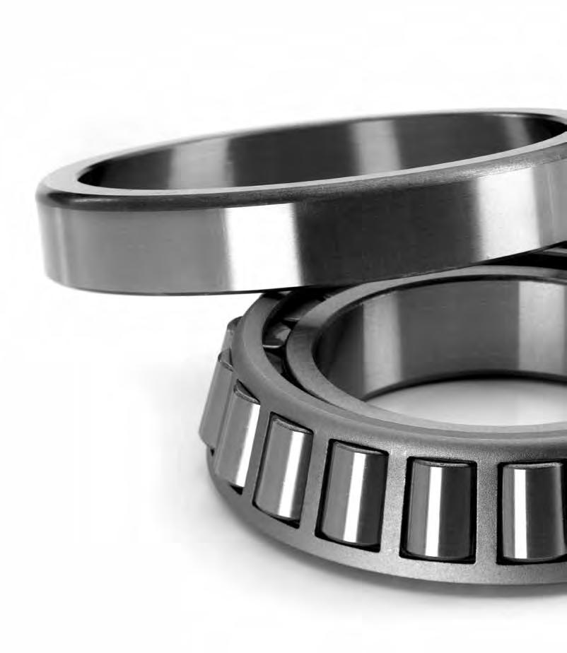
266
267 TAPERED ROLLER BEARINGS Dimensions in accordance with ISO 355 (1979) Tapered roller bearings are designed to take radial and thrust loads from one direction. They consist of the inner race (cone) with cage guided rollers and the outer race (cup) the track having the same profile as the tapered rollers. The extension of the contact lines meet at a common point on the bearing axis of rotation. The cone and cup are seperable. By using two bearings as opposed mountings they can carry thrust loadings in both directions. Single row tapered roller bearings can be supplied matched in DB or DF arrangement. These matched bearings are so manufactured that when they are mounted opposite to each other, the pair should have an established initial axial clearance and a uniform distribution of the loading. Matched bearings are used when the load carrying capacity of a single bearing is not sufficient or when the thrust loads have to be carried at a certain axial clearance in both directions. Axial clearance The axial clearance of single tapered roller bearings is adjusted on assembly. With matched bearings, as with double and 4 row bearings, axial clearance is achieved by the addition of spacer rings ground to give the required clearance. Radial clearances fort classes recommended for double and four row tapered roller bearings are shown in the technical section. The radial clearance is transformed into axial clearance by the following relation : Axial clearance = Radial clearance 2 tan α Where: α = contact angle between rollers and the outer ring raceway 265
268 TAPERED ROLLER BEARINGS Basic types and design variants Single row Matched R DF DB Double row Four row 266
269 Tapered roller bearings Bearing ISO dimensions Load ratings Speed limits Weight Dimensions Calculation factors Type Vers. d D T C Co Grease Oil B C r1,2 r3,4 r5 a e Y Y0 mm kn kn r/min r/min kg ,75 15,8 14,4 0, ,0 0,6 0, ,25 23,9 21, , , ,3 9,00 0,28 2,1 1, ,25 21,2 21, , , ,3 10,00 0,35 1,7 0, ,25 29,7 27, , , ,3 10,00 0,28 2,1 1, , , ,0 0,6 0,6 0,3 10,00 0,37 1,6 0, ,25 28,2 30, , , ,3 11,00 0,35 1,7 0, ,25 34,7 33, , ,0 1,5 1,5 0,6 11,00 0,3 2 1, , ,6 0, , ,25 44,6 46, , ,0 1,5 1,5 0,6 14,00 0,3 2 1, ,25 29,4 22, , , ,3 12,00 0,37 1,6 0, ,25 49,2 48, , ,0 1,5 1,5 0,6 13,00 0,3 2 1, A ,25 40,7 46, , ,0 1,5 1,5 0,6 20,00 0,83 0,7 0, , , ,5 0,6 0,6 0,3 11,60 0,43 1,39 0, , , , ,3 16,00 0,33 1, ,25 64,6 68, , ,0 1,5 1,5 0,6 15,00 0,3 2 1, ,5 42,5 0, ,0 0,6 0, ,1 55,8 0, , ,25 45,4 50, , , ,3 14,00 0,37 1,6 0, ,75 61,7 63, , ,0 1,5 1,5 0,6 15,00 0,31 1,9 1, ,75 52,5 60, , ,0 1,5 1,5 0,6 22,00 0,83 0,7 0, , , , ,3 13,00 0,43 1,4 0, ,25 54,3 63, , , ,3 15,00 0,37 1,6 0, ,75 85,5 96, , ,0 1,5 1,5 0,6 18,00 0,31 1,9 1, ,25 56,8 63, , ,0 1,5 1,5 0,6 15,00 0,37 1,6 0,9 267
270 Tapered roller bearings Bearing ISO dimensions Load ratings Speed limits Weight Dimensions Calculation factors Type Vers. d D T C Co Grease Oil B C r1,2 r3,4 r5 a e Y Y0 mm kn kn r/min r/min kg ,75 78,8 82, , ,0 2 1,5 0,6 16,00 0,31 1,9 1, ,75 67,9 76, , ,0 2 1,5 0,6 25,00 0,83 0,7 0, ,9 52, , , ,3 15,00 0,46 1,3 0, , , ,3 15,00 0,46 1,3 0, , , , ,0 1,5 1,5 0,6 17 0,37 1,6 0, , ,75 103,6 118, , ,0 2 1,5 0,6 20,00 0,31 1,9 1, , , ,0 1,5 1,5 0,6 16,00 0,37 1,6 0, ,25 95,2 107, , ,0 2 1,5 0,6 19,00 0,35 1,7 0, ,25 81,4 96, , ,0 2 1,5 0,6 28,00 0,83 0,7 0, , , , ,3 15,00 0,37 1,6 0, ,8 65, , , ,3 15,00 0,37 1,6 0, ,75 77,9 97, , ,0 1,5 1,5 0,6 19 0,37 1,6 0, ,25 120,8 147, , ,0 2 1,5 0,6 23,00 0,35 1,7 0, ,75 71,3 83, , ,0 1,5 1,5 0,6 18,00 0,4 1,5 0, ,25 114,05 129, , ,0 2 1,5 0,6 21,00 0,35 1,7 0, ,25 95,6 113, , ,0 2 1,5 0,6 31 0,83 0,7 0, , , , ,3 16,00 0,4 1,5 0, ,6 80, , , ,3 16,00 0,4 1,5 0, ,75 84, , ,0 1,5 1,5 0,6 20,00 0,4 1,5 0, ,25 145,3 189, , ,0 2 1,5 0,6 25,00 0,35 1,7 0, ,1 117,2 0, ,5 1,5 1, ,5 145,1 0, ,
271 Bearing ISO dimensions Load ratings Speed limits Weight Dimensions Calculation factors Type Vers. d D T C Co Grease Oil B C r1,2 r3,4 r5 a e Y Y0 mm kn kn r/min r/min kg ,75 73,3 92, , ,0 1,5 1,5 0,6 19,00 0,43 1,4 0, ,25 130,1 157, , ,0 2,5 2 0,6 23 0,35 1,7 0, , , , ,0 2,5 2 0,6 34 0,83 0,7 0, , , ,3 18 0,43 1,4 0, ,5 88, , , ,3 18 0,43 1,4 0, ,75 86,7 107, , ,0 1,5 1,5 0,6 21,00 0,43 1,4 0, ,25 177,5 236, , ,0 2,5 2 0,6 27 0,35 1,7 0, ,2 111, ,5 126, , ,0 1,5 1,5 20,00 0,4 1,5 0, ,75 94,6 112, , ,0 2 1,5 0,6 20,00 0,4 1,5 0, ,5 153,3 187, , ,0 2,5 2 0,6 24 0,35 1,7 0, ,5 129, , ,0 2,5 2 0,6 37 0,83 0,7 0, , ,5 1,5 1,5 0,6 20 0,4 1,5 0, ,7 115, , ,5 1,5 1,5 0,6 20 0,4 1,5 0, ,75 112,7 141, , ,0 2 1,5 0,5 22,83 0,4 1,48 0, ,5 212,7 271, , ,0 2,5 2 0,6 29 0,35 1,7 0, ,5 162, ,75 103, , ,0 2 1,5 0,6 22,00 0,4 1,5 0, ,5 171, , ,0 3 2, ,35 1,7 0, ,5 145,4 176, , ,0 3 2, ,83 0,7 0, , , ,5 1,5 1,5 0,6 21 0,43 1,4 0, ,8 121, , ,5 1,5 1,5 0,6 21 0,43 1,4 0, ,75 132,8 179, , ,0 2 1,5 0,6 24 0,4 1,5 0,8 269
272 Tapered roller bearings Bearing ISO dimensions Load ratings Speed limits Weight Dimensions Calculation factors Type Vers. d D T C Co Grease Oil B C r1,2 r3,4 r5 a e Y Y0 mm kn kn r/min r/min kg ,5 226, , ,0 3 2, ,35 1,7 0, , ,8 231, , ,0 2 1,5 0,6 28 0,4 1,48 0, ,75 120,6 152, , ,0 2 1,5 0,6 23 0,4 1,5 0, ,9 241, , ,0 3 2, ,35 1,7 0, ,7 202, , ,0 3 2, ,83 0,7 0, , , ,5 1,5 1,5 0,6 22 0,46 1,3 0, ,75 160,9 221, , ,0 2 1,5 0,6 27 0,4 1,5 0, , ,0 3 2, ,35 1,7 0, ,5 162, ,6 224, , ,5 1,5 1, ,2 281, , ,0 2 1,5 0,5 29,50 0,39 1,53 0, ,25 138,3 173, , ,0 2 1,5 0,6 25 0,43 1,4 0, , , ,0 3 2, ,35 1,7 0, , , ,0 1,5 1,5 0,6 23 0,43 1,4 0, ,25 168,5 237, , ,0 2 1,5 0,6 28 0,43 1,4 0, , ,0 3 2, ,35 1,7 0, , , , ,0 2 1,5 0,8 30,7 0,41 1,47 0, ,25 138,4 185, , ,0 2 1,5 0,6 27 0,43 1,4 0, ,8 318, , ,0 3 2, ,35 1,7 0, , ,0 3 2, ,83 0,7 0, ,1 160, , ,0 1,5 1,5 0,6 25 0,46 1,3 0,7 270
273 Bearing ISO dimensions Load ratings Speed limits Weight Dimensions Calculation factors Type Vers. d D T C Co Grease Oil B C r1,2 r3,4 r5 a e Y Y0 mm kn kn r/min r/min kg , , ,0 1,5 1,5 0,6 25 0,46 1,3 0, ,25 170,3 242, , ,0 2 1,5 0,6 29 0,43 1,4 0, , ,0 3 2, ,35 1,7 0, , , , ,25 167,7 212, , ,0 2,5 2 0,6 28 0,43 1,4 0, ,5 278,8 352, , ,0 3 2, ,35 1,7 0, , , ,0 3 2, ,83 0,7 0, , ,0 1,5 1,5 0,6 27 0,43 1,4 0, ,25 198, , ,0 2,5 2 0,6 30 0,43 1,4 0, ,5 387,9 543, , ,0 3 2, ,35 1,7 0, , , ,0 2 1, , ,5 177,6 236, , ,0 2,5 2 0,6 30 0,43 1,4 0, , , , ,35 1,7 0, , , , , ,0 1,5 1,5 0,6 28 0,44 1,4 0, , , ,0 2,5 2 0,6 33 0,43 1,4 0, , , , ,35 1,7 0, , , , , , ,35 1,7 0,9 271
274 Tapered roller bearings Bearing ISO dimensions Load ratings Speed limits Weight Dimensions Calculation factors Type Vers. d D T C Co Grease Oil B C r1,2 r3,4 r5 a e Y Y0 mm kn kn r/min r/min kg , , , ,83 0,7 0, , ,0 2 1,5 0,6 30 0,43 1,4 0, , , ,0 2,5 2 0,6 36 0,43 1,4 0, A , , , ,5 46,2 0,35 1,74 0, , , ,0 2, ,4 1,5 0, , , ,2 3 2,5 1,2 27 0,43 1,4 0, , , , ,35 1,7 0, , ,0 2 1,5 0,6 31 0,44 1,4 0, , , , , ,0 3 2, ,43 1,4 0, , , , ,35 1,7 0, , ,5 2 1,5 0,6 27,6 0,28 2,16 0, , ,0 3 2, ,43 1,4 0, , , , ,35 1,7 0, , , ,0 2 1,5 0,6 32 0,46 1,3 0, , ,0 3 2, ,43 1,4 0, , ,5 0,5 1, , , , , ,35 1,7 0, , ,0 3 2, ,43 1,4 0, , , , ,0 2,5 2 0,6 34 0,44 1,4 0,8 272
275 Bearing ISO dimensions Load ratings Speed limits Weight Dimensions Calculation factors Type Vers. d D T C Co Grease Oil B C r1,2 r3,4 r5 a e Y Y0 mm kn kn r/min r/min kg , ,0 3 2, ,43 1,4 0, A , , , ,35 1,7 0, ,0 2, , , ,0 3 2, ,43 1,4 0, , , , ,35 1,7 0, , ,7 403, , ,6 2, ,6 0,43 1,4 0, , ,0 3 2, ,43 1,4 0, , , , ,35 1,7 0, , , , , ,0 3 2, ,43 1,4 0, , , , ,35 1,7 0, , , , ,0 2,5 2 0,6 39 0,46 1,3 0, , , ,0 3 2, ,43 1,4 0, , , , ,35 1,7 0, , , , , , ,43 1,4 0, , , , ,5 51 0,35 1,7 0, , , ,5 87 0,83 0,7 0, X , ,0 2, ,3 0,43 1,38 0,76 273
276 Tapered roller bearings Bearing ISO dimensions Load ratings Speed limits Weight Dimensions Calculation factors Type Vers. d D T C Co Grease Oil B C r1,2 r3,4 r5 a e Y Y0 mm kn kn r/min r/min kg , , , ,43 1,4 0, , , , ,5 66 0,35 1,7 0, A , , , ,44 1,4 0, A , , , ,35 1,7 0, , ,0 2,5 2 0,6 46 0,46 1,3 0, , , , ,43 1,4 0, A , , , ,37 1,6 0, , , ,43 1,4 0, , , ,0 3 2, ,46 1,3 0, , , ,43 1,4 0, , , , , ,43 1,4 0, , , ,0 3 2, ,46 1,3 0, , , ,43 1,4 0, A , , ,35 1,7 0, , , ,5 58 0,43 1,4 0, , , ,0 3 2, ,44 1,4 0, , , ,5 75 0,43 1,4 0, , , ,5 61 0,46 1,3 0, , ,0 3 2, ,43 1,4 0,8 274
277 Bearing ISO dimensions Load ratings Speed limits Weight Dimensions Calculation factors Type Vers. d D T C Co Grease Oil B C r1,2 r3,4 r5 a e Y Y0 mm kn kn r/min r/min kg A , , ,45 1,3 0, , , ,0 3 2, ,44 1,4 0, , , ,5 81 0,43 1,4 0, , ,0 2, ,38 1,6 0, , , ,44 1,4 0, , ,0 3 2, ,43 1,4 0, , , ,41 1,5 0, , , ,5 54 0,39 1,5 0, , , ,42 1,4 0, , , ,43 1,4 0, , , ,44 1,4 0, , ,0 3 2,5 1 56,1 0,37 1,6 0, , , ,46 1,3 0, , , ,43 1,4 0, , , ,5 64 0,46 1,3 0, , , ,5 84 0,43 1,4 0, , , ,43 1,4 0, , , ,32 1,9 1, , , , ,5 60 0,3 2 1, , , ,37 1,6 0, , , ,5 64 0,32 1,9 1, , , ,28 2,1 1, , , ,43 1,4 0,8 275

278 Tapered roller bearings Bearing ISO dimensions Load ratings Speed limits Weight Dimensions Calculation factors Type Vers. d D T C Co Grease Oil B C r1,2 r3,4 r5 a e Y Y0 mm kn kn r/min r/min kg , , ,43 1,4 0, , , ,43 1,4 0, , , ,46 1,3 0, , ,0 7,5 7,5 7, ,6 1 0, , , ,44 1,35 0, , , ,46 1,3 0, , ,0 7,5 7,5 7, ,6 1 0, , , ,7 0,86 0, , ,0 7,5 7,5 7, ,57 1,05 0, , ,0 9,5 9,5 9, ,54 1,1 0,6 306/ , ,0 9,5 9,5 9, ,43 1,4 0,8 329/ , , ,46 1,3 0,72 306/ , ,0 7,5 7,5 7, ,43 1,4 0,78 306/ , , ,43 1,4 0,8 319/ , , ,46 1,3 0,72 306/ , ,0 7,5 7,5 7, ,46 1,3 0,72 276
279 277
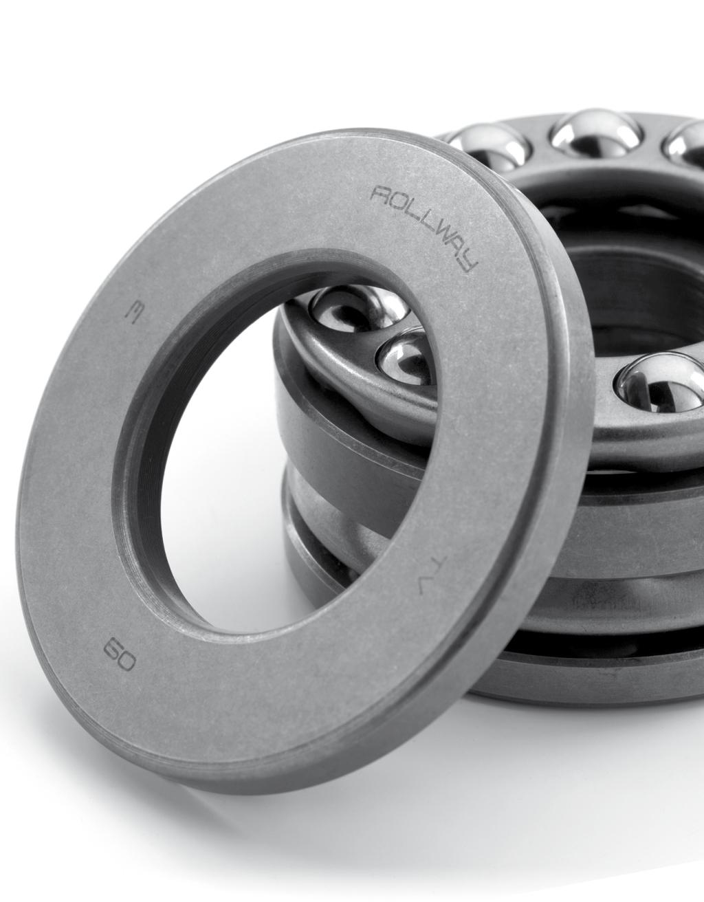
280
281 THRUST BALL BEARINGS Dimensions in accordance with ISO 104 (1979) Thrust ball bearings are available in single and double acting versions. They provide for axial loads only, and therefore should not be used where radial loads are present. The thrust loading should not drop below a minimum axial load, thus maintaining contact between the balls and the track when centrifugal forces are present. They are manufactured in the following series 511, 512, 513, 514, 522, 523 and , 512, 513, , 523,
282 THRUST BALL BEARINGS Single acting thrust ball bearigs Single acting thrust ball bearings are used to carry thrust loads in only one direction and cannot carry radial loads. They are made up of shaft washer, a flat housing washer and a ball and cage assembly. These bearings can easely mounted by separately fittings each washer. Double acting thrust ball bearing These bearing can carry thrust loadings in both directions. They are fitted with an extra thrust washer and two ball and cage assemblies. See technical section for further information. Minimum load For a thrust ball bearing to function correctly it requires axial load in order to ensure that the rolling elements maintain contact with the raceways. This prevents wear due to sliding. Fam can be obtained from formula. 2 Fam = M n Max [ ] [N] 1000 Where: Fam = minimum thrust load (N) M = Factor for minimum load n = speed in RPM 280
283 Single row thrust ball bearings Bearing ISO dimensions Load ratings Speed limits Weight Dimensions Type Version d D H C Co Grease Oil D1 d1 r1,2 mm kn kn r/min r/min kg min ,0 14, , , ,2 15, , , ,2 19, , , ,5 16, , , ,5 24, , , ,8 18, , , ,0 27, , , ,2 24, , , ,2 37, , , ,2 30, , , ,8 50, , , ,5 61, , , ,0 34, , , ,0 54, , , ,8 78, , , ,2 41, , , ,2 78, , , ,2 105, , , ,8 62, , , ,8 91, , , ,2 135, , , ,0 66, , , ,8 105, , , ,8 150, , ,0 281
284 Single row thrust ball bearings Bearing ISO dimensions Load ratings Speed limits Weight Dimensions Type Version d D H C Co Grease Oil D1 d1 r1,2 mm kn kn r/min r/min kg min ,2 69, , , ,5 112, , , , , , ,8 89, , , ,5 158, , , ,0 242, , , ,2 108, , , ,5 178, , , ,0 262, , , ,5 112, , , ,8 188, , , ,0 262, , , ,8 115, , , ,5 188, , , ,0 340, , , ,2 140, , , ,8 198, , , ,0 380, , , ,5 145, , , ,8 222, , , ,0 380, , , ,2 150, , , ,0 280, , , ,0 495, , ,5 282
285 Bearing ISO dimensions Load ratings Speed limits Weight Dimensions Type Version d D H C Co Grease Oil D1 d1 r1,2 mm kn kn r/min r/min kg min ,0 200, , , ,0 315, , , ,0 495, , , ,0 268, , , ,0 375, , , ,0 595, , , , , , , , , , , , , , , M , , , M , , , M , , , M , , , M , , , M , , , M , , , M , , , M , , , M , , , M , , , M , , , M , , , M , , ,7 283

286 Single row thrust ball bearings Bearing ISO dimensions Load ratings Speed limits Weight Dimensions Type Version d D H C Co Grease Oil D1 d1 r1,2 mm kn kn r/min r/min kg min M , , , M , , , M , , , M , , , M , , , M , , , M , , , M , , , M , , , M , , , M , , , M , , , M , , , M , , , M , , ,0 284
287 Double rows thrust ball bearings Bearing ISO dimensions Load ratings Speed limits Weight Calculation factors Type Version d D H C Co Grease Oil D1 B rs r1s mm kn kn r/min r/min kg min min , ,6 0, , ,6 0, , ,0 0, , ,6 0, , ,0 0, , ,0 0, , ,6 0, , ,0 0, , ,1 0, , ,0 0, , ,0 0, , ,0 0, , ,0 0, , ,1 0, , ,0 0, , ,0 0, , ,1 0, , ,0 0, , ,1 0, , ,5 0, , ,0 0, , ,1 0, , ,5 0, , ,0 0,6 285

288 Double rows thrust ball bearings Bearing ISO dimensions Load ratings Speed limits Weight Calculation factors Type Version d D H C Co Grease Oil D1 B rs r1s mm kn kn r/min r/min kg min min , ,1 0, , ,5 0, , ,0 1, , ,0 0, , ,0 1, , ,1 0, , ,1 1, , ,0 1, , ,5 1, , ,0 1, , ,5 1, , ,0 1, , ,5 1, , ,1 1, , ,5 1, , ,0 1, , ,1 1, , ,5 1, , ,1 1, , ,0 1, , ,1 1, , ,1 1, , ,5 1, , ,5 1,1 286
289 Bearing ISO dimensions Load ratings Speed limits Weight Calculation factors Type Version d D H C Co Grease Oil D1 B rs r1s mm kn kn r/min r/min kg min min , ,5 1, , ,1 1, , ,5 1, , ,1 1, , ,5 1,1 287

290
291 SPHERICAL ROLLER THRUST BEARINGS Dimensions in accordance with ISO 104 (1979) These bearings can accommodate heavy thrust loads and, due to raceways being inclined to the bearings axis, they can also accommodate radial loads up to a maximum of 55% of the thrust load and are suitable for taking high thrust loads at relatively high speed. Misalignment depends on the series ( figures show below). Series Misalignment The bearings are fitted with asymmetrical barrel-shaped rollers. Dimensions conform to ISO Lubrication of these bearings should be by oil except in certain exceptional cases. It is also essential that a minimum thrust load be present to avoid damage to the raceways by centrifugal forces (see formula below). Fa min = 1.5 cor 1000 [KN] Where Fa min = minimum thrust load [KN] Cor = static capacity [KN] 289

292 Spherical roller thrust bearings Bearing ISO dimensions Load ratings Speed limits Weight Calculation factors Type Version d D H C Co Grease Oil d1 D1 B C a r1,2 mm kn kn r/min r/min kg min min min EM ,5 967, ,75 85, ,5 38 1, EM , ,41 91, , EM ,1 99, ,5 23, EM ,98 106, , EM ,95 112, , , EM ,87 110, ,4 50 1, EM ,19 119, ,5 54 2, EM ,06 115, ,8 52 1, EM ,28 125, ,7 29,3 56 2, EM ,91 127, ,5 21,2 58 1, EM ,2 141, , EM ,67 141, , EM ,7 154, , EM ,96 155, ,2 70 2, EM ,5 168, , EM ,45 167, ,5 28,3 76 2, EM ,6 181, ,5 41, EM ,2 178, ,5 29,6 82 2, EM ,6 192, ,5 41, EM ,7 188, , EM ,6 205, , EM ,5 204, EM ,9 218, , EM ,54 199, ,5 290
293 Bearing ISO dimensions Load ratings Speed limits Weight Calculation factors Type Version d D H C Co Grease Oil d1 D1 B C a r1,2 mm kn kn r/min r/min kg min min min EM ,3 214, , EM , ,5 50, EM ,05 208, , EM ,7 227, ,2 35, EM ,2 247, ,5 52, EM ,95 220, , EM ,5 240, ,5 39, EM ,4 260, , EM ,08 230, EM , , EM , , EM ,84 249, , EM ,5 275, , EM ,2 275, , EM ,1 278, , , EM ,3 297, , EM , ,5 60, EM ,5 300, ,5 30, , EM ,5 323, ,8 48, EM , , EM ,5 321, , EM , , EM , , EM , ,5 36,
294 Spherical roller thrust bearings Bearing ISO dimensions Load ratings Speed limits Weight Calculation factors Type Version d D H C Co Grease Oil d1 D1 B C a r1,2 mm kn kn r/min r/min kg min min min EM ,6 370, , EM , , EM ,8 368, , EM , , EM , ,5 76, , EM ,5 389, ,5 36, EM , ,5 60, EM , , , EM ,4 417, , EM , , EM , , , EM ,8 437, , EM , ,5 66, EM , , , EM ,1 457, ,3 42, EM , , EM , , EM ,9 483, , EM , ,5 70, EM , , , EM , , EM , , EM , , EM ,9 524, ,
295 Bearing ISO dimensions Load ratings Speed limits Weight Calculation factors Type Version d D H C Co Grease Oil d1 D1 B C a r1,2 mm kn kn r/min r/min kg min min min EM , , EM , , EM , ,5 52, EM , EM ,2 623, ,5 111, ,5 292/500 EM , , /500 EM , , /500 EM , , ,5 292/530 EM , , /530 EM , , ,5 294/530 EM , , ,5 292/560 EM , , /560 EM ,5 294/560 EM , /600 EM , /600 EM , ,5 294/600 EM , , /630 EM ,0 814, , /630 EM ,5 294/630 EM /670 EM , /670 EM ,5 292/710 EM /710 EM ,5 293
296 Spherical roller thrust bearings Bearing ISO dimensions Load ratings Speed limits Weight Calculation factors Type Version d D H C Co Grease Oil d1 D1 B C a r1,2 mm kn kn r/min r/min kg min min min 294/710 EM , /750 EM , /750 EM ,5 294/750 EM , /800 EM ,0 907, ,5 293/800 EM ,5 292/850 EM ,5 292/900 EM ,0 1129, ,5 294
297 OTHER PRODUCTS The rollway production program also includes: Slewing ring bearings Full complement cylindrical roller bearings Tandem thrust bearings Multi stage thrust bearings Cross roller bearings Screw down bearings 295
298 SI-Standard Force 1KN ( kilonewton) = 1000 N = 102 kp 1 kp = 9.81 N Pressure 1 bar = 10 N/cm = 1.02 kp/cm² 1 kp / cm² = 9.81 N/cm² = bar Mechanical stress, surface pressure 1 N/mm² = 1 MPa (megapascal) = kp/mm² 1kp /mm² = 9.81 N/mm² Torsional moment 1Nm = kpm 1 kpm = 9.81Nm Output 1w = 1 J7s = Nm/s = kpm/s 1 kw = 1.36 hp = 102kpm/s 1 hp = kw = 75 kpm/s 1kpm/s = 9.81 W Kinematic viscosity 1mm²/s = 1 cst ( centistokes) 296
299 CONVERSION TABLES Millimeters to inches 1 mm = inches mm inches mm inches mm inches mm inches mm
300 CONVERSION TABLES Inches to millimeters 1 inch = 25.4mm inches mm inches mm inches mm inches mm inches mm inches mm inches mm inches mm
301 inches mm inches mm inches mm inches mm inches
302 All sales are made on our STANDARD TERMS AND CONDITIONS OF SALE in effect at the time a customer s order is accepted. The current Terms and Conditions are set forth below: STANDARD TERMS AND CONDITIONS OF SALE (October 25, 2012) These Terms and Conditions, the attendant quotation or acknowledgment and all documents incorporated by specific reference therein, will be the complete and exclusive statement of the terms of the agreement governing the sale of goods ( Goods ) by Emerson Power Transmission Corporation and its divisions and subsidiaries ( Seller ) to Customer ( Buyer ). Buyer s acceptance of the Goods will manifest Buyer s assent to these Terms and Conditions. If these Terms and Conditions differ in any way from the terms a nd conditions of Buyer s order, or other documentation, this document will be construed as a counteroffer and will not be deemed an acceptance of Buyer s terms and conditions which conflict herewith. 1. PRICES: Unless otherwise specified in writing by Seller, Seller s price for the goods shall remain in effect for thirty (30) days after the date of Seller s quotation or acknowledgment of Buyer s order for the Goods, whichever occurs first, provided an unconditional, complete authorization for the immediate shipment of the Goods is received and accepted by Seller within such time period. If such authorization is not received by Seller within such thirty (30) day period, Seller shall have the right to change the price for the Good to Seller s price for the Goods at the time of shipment. 2. TAXES: Any tax or governmental charge or increase in same hereafter becoming effective increasing the cost to Seller of producing, selling or delivering the Goods or of procuring material used therein, and any tax now in effect or increase in same payable by the Seller because of the manufacture, sale or delivery of the Goods, may at Seller s option, be added to the price. 3. TERMS OF PAYMENT: Subject to the approval of Seller s Credit Department, terms are net thirty (30) days from date of Seller s invoice in U.S. currency. If any payment owed to Seller is not paid when due, it shall bear interest, at a rate to be determined by Seller, which shall not exceed the maximum rate permitted by law, from the date on which it is due until it is paid. Seller shall have the right, among other remedies, either to terminate the Agreement or to suspend further performance under this and/or other agreements with Buyer in the event Buyer fails to make any payment when due. Buyer shall be liable for all expenses, including attorneys fees, relating to the collection of past due amounts. 4. SHIPMENT AND DELIVERY: Shipments are made F.O.B. Seller s shipping point. Any claims for shortages or damages suffered in transit shall be submitted by the Buyer directly to the carrier. While Seller will use all reasonable commercial efforts to maintain the delivery date acknowledged or quoted by Seller, all shipping dates are approximate. Seller reserves the right to make partial shipments and to segregate specials and made-to-order Goods from normal stock Goods. Seller shall not be bound to tender delivery of any Goods for which Buyer has not provided shipping instructions. 5. QUANTITY: Buyer agrees to accept overruns of up to ten percent (10%) of the order on made-to-order Goods, including parts. Any such additional items shall be priced at the price per item charged for the specific quantity ordered. 6. LIMITED WARRANTY: Subject to the limitations of Section 7, Seller warrants that the Goods will be free from defects in material and workmanship under normal use, service and maintenance for a period of one year (unless otherwise specified by Seller in writing) from the date of shipment of the Goods by Seller. THIS IS THE SOLE AND EXCLUSIVE WARRANTY GIVEN BY SELLER WITH RESPECT TO THE GOODS AND IS IN LIEU OF AND EXCLUDES ALL OTHER WARRANTIES, EXPRESS OR IMPLIED, ARISING BY OPERATION OF LAW OR OTHERWISE, INCLUDING WITHOUT LIMITATION, MERCHANTABILITY OR FITNESS FOR A PARTICULAR PURPOSE WHETHER OR NOT THE PURPOSE OR USE HAS BEEN DISCLOSED TO SELLER IN SPECIFICATIONS, DRAWINGS OR OTHERWISE, AND WHETHER OR NOT SELLER S PRODUCTS ARE SPECIFICALLY DESIGNED AND/OR MANUFACTURED BY SELLER FOR BUYER S USE OR PURPOSE. This warranty does not extend to any losses or damages due to misuse, accident, abuse, neglect, normal wear and tear, unauthorized modification or alteration, use beyond rated capacity, or improper installation, maintenance or application. To the extent that Buyer or its agents has supplied specifications, information, representation of operating conditions or other data to Seller in the selection or design of the Goods and the preparation of Seller s quotation, and in the event that actual operating conditions or other conditions differ from those represented by Buyer, any warranties or other provisions contained herein which are affected by such conditions shall be null and void. If within thirty (30) days after Buyer s discovery of any warranty defects within the warranty period, Buyer notifies Seller thereof in writing, Seller shall, at its option, repair or replace F.O.B. point of manufacture, or refund the purchase price for, that portion of the goods found by Seller to be defective. Failure by Buyer to give such written notice within the applicable time period shall be deemed an absolute and unconditional waiver of Buyer s claim for such defects. Goods repaired or replaced during the warranty period shall be covered by the foregoing warranty for the remainder of the original warranty period or ninety (90) days, whichever is longer. Buyer assumes all other responsibility for any loss, damage, or injury to persons or property arising out of, connected with, or resulting from the use of Goods, either alone or in combination with other products/components. SECTIONS 6 AND 7 APPLY TO ANY ENTITY OR PERSON WHO MAY BUY, ACQUIRE OR USE SELLER S GOODS, INCLUDING ANY ENTITY OR PERSON WHO BUYS THE GOODS FROM SELLER S DISTRIBUTOR AND SUCH ENTITY OR PERSON SHALL BE BOUND BY THE LIMITATIONS THEREIN. 7. LIMITATION OF REMEDY AND LIABILITY: THE SOLE AND EXCLUSIVE REMEDY FOR BREACH OF ANY WARRANTY HEREUNDER (OTHER THAN THE WARRANTY PROVIDED UNDER SECTION 13) SHALL BE LIMITED TO REPAIR, REPLACEMENT OR REFUND OF THE PURCHASE PRICE UNDER SECTION 6. SELLER SHALL NOT BE LIABLE FOR DAMAGES CAUSED BY DELAY IN PERFORMANCE AND IN NO EVENT, REGARDLESS OF THE FORM OF THE CLAIM OR CAUSE OF ACTION (WHETHER BASED IN CONTRACT, INFRINGEMENT, NEGLIGENCE, STRICT LIABILITY, OTHER TORT OR OTHERWISE), SHALL SELLER S LIABILITY TO BUYER AND/OR ITS CUSTOMERS EXCEED THE PRICE TO BUYER OF THE SPECIFIC GOODS PROVIDED BY SELLER GIVING RISE TO THE CLAIM OR CAUSE OF ACTION. BUYER AGREES THAT IN NO EVENT SHALL SELLER S LIABILITY TO BUYER

303 AND/OR ITS CUSTOMERS EXTEND TO INCLUDE INCIDENTAL, CONSEQUENTIAL OR PUNITIVE DAMAGES. THE TERM CONSEQUENTIAL DAMAGES SHALL INCLUDE, BUT NOT BE LIMITED TO, LOSS OF ANTICIPATED PROFITS, LOSS OF USE, LOSS OF REVENUE, COST OF CAPITAL AND DAMAGE OR LOSS OF OTHER PROPERTY OR EQUIPMENT. It is expressly understood that any technical advice furnished by Seller with respect to the use of the Goods is given without charge, and Seller assumes no obligation or liability for the advice given, or results obtained, all such advice being given and accepted at Buyer s risk. GOODS AND/OR SERVICES SOLD HEREUNDER ARE NOT FOR USE IN ANY NUCLEAR AND RELATED APPLICATIONS. Buyer accepts goods and/or services with the foregoing understanding, agrees to communicate the same in writing to any subsequent purchaser or users and to defend, indemnify and hold harmless Seller from any claims, losses, suits, judgments and damages, including incidental and consequential damages, arising from such use, whether the cause of action be based in tort, contract or otherwise, including allegations that the Seller s liability is based on negligence or strict liability. 8. EXCUSE OF PERFORMANCE: Seller shall not be liable for delays in performance or for non-performance due to acts of God, acts of Buyer, war, riot, fire, flood, other severe weather, sabotage, or epidemics; strikes or labor disturbances; governmental requests, restrictions, laws, regulations, orders or actions; unavailability of or delays in transportation; default of suppliers; or unforeseen circumstances or any events or causes beyond Seller s reasonable control. Deliveries may be suspended for an appropriate period of time as a result of the foregoing. If Seller determines that its ability to supply the total demand for the Goods, or to obtain material used directly or indirectly in the manufacture of the Goods, is hindered, limited or made impracticable due to causes addressed in this Section 8, Seller may allocate its available supply of the Goods or such material (without obligation to acquire other supplies of any such Goods or material) among itself and its purchasers on such basis as Seller determines to be equitable without liability for any failure of performance which may result therefrom. Deliveries suspended or not made by reason of this section may be canceled by Seller upon notice to Buyer without liability, but the balance of the agreement shall otherwise remain unaffected. 9. CANCELLATIONS AND DELAYS: The Buyer may cancel orders only upon written notice and upon payment to Seller of cancellation charges which include, among other things, all costs and expenses incurred and commitments made by the Seller and a reasonable profit thereon. Any request by Buyer to extend the delivery schedule must be agreed to in writing by the Seller. If agreement cannot be reached, Seller may deliver product to the last known ship to address and invoice the Buyer upon completion of the product or prior delivery date, whichever is later. 10. CHANGES: Buyer may request changes or additions to the Goods consistent with Seller s specifications and criteria. In the event such changes or additions are accepted by Seller, Seller may revise the price and delivery schedule. Seller reserves the right to change designs and specifications for the Goods without prior notice to Buyer, except with respect to Goods being madeto-order for Buyer. 11. TOOLING: Tool, die, and pattern charges, if any, are in addition to the price of the Goods and are due and payable upon completion of the tooling. All such tools, dies and patterns shall be and remain the property of Seller. Charges for tools, dies, and patterns do not convey to Buyer, title, ownership interests in, or rights to possession or removal, nor prevent their use by Seller for other purchasers, except as otherwise expressly provided by Seller and Buyer in writing with reference to this provision. 12. ASSIGNMENT: Buyer shall not assign its rights or delegate its duties hereunder or any interest therein or any rights hereunder without the prior written consent of the Seller, and any such assignment, without such consent, shall be void. 13. PATENTS AND COPYRIGHTS: Subject to Section 7, Seller warrants that the Goods sold, except as are made specifically for Buyer according to Buyer s specifications, do not infringe any valid U.S. patent or copyright in existence as of the date of delivery. This warranty is given upon the condition that Buyer promptly notify Seller of any claim or suit involving Buyer in which such infringement is alleged, and, that Buyer cooperate fully with Seller and permit Seller to control completely the defense or compromise of any such allegation of infringement. Seller s warranty as to use only applies to infringements arising solely out of the inherent operation (i) of such Goods, or (ii) of any combination of Goods in a system designed by Seller. In the event such Goods, singularly or in combination, are held to infringe a U.S. patent or copyright in such suit, and the use of such Goods is enjoined, or in the case of a compromise by Seller, Seller shall have the right, at its option and expense, to procure for Buyer the right to continue using such Goods, or replace them with non-infringing Goods; or modify same to become noninfringing; or grant Buyer a credit for the depreciated value of such Goods and accept return of them. 14. EXPORT/IMPORT: Buyer agrees that all applicable import and export control laws, regulations, orders, and requirements, including without limitation those of the United States and the European Union, and the jurisdictions in which the Seller and the Buyer are established or from which Goods may be supplied, will apply to their receipt and use. In no event shall Buyer use, transfer, release, import, or export Goods in violation of such applicable laws, regulations, orders or requirements. 15. MISCELLANEOUS: These terms and conditions set forth the entire understanding and agreement between Seller and Buyer, and supersede all other communications, negotiations and prior oral or written statements regarding the subject matter of these terms and conditions. No change, modification, rescission, discharge, abandonment, or waiver of these terms and conditions of Sale shall be binding upon the Seller unless made in writing and signed on its behalf by an officer of the Seller. No conditions, usage or trade, course of dealing or performance, understanding or agreement purporting to modify, vary, explain, or supplement these Terms and Conditions shall be binding unless hereafter made in writing and signed by the party to be bound, and no modification shall be affected by the acceptance of purchase orders or shipping instruction forms containing terms at variance with or in addition to those set forth herein. Any such modifications or additional terms are specifically rejected by Seller. No waiver by Seller with respect to any breach or default or any right or remedy and no course of dealing, shall be deemed to constitute a continuing waiver of any other breach or default or of any other right or remedy, unless such waiver be expressed in writing and signed by the party to be bound. Seller is not responsible for typographical or clerical errors made in any quotation, orders or publications. All such errors are subject to correction. The validity, performance, and all other matters relating to the interpretation and effect of this contract shall be governed by the law of the state of New York. The United Nations Convention on the International Sale of Goods shall not apply to any transaction hereunder.
TECHNICAL INFORMATION
 General Nomenclature Spherical Roller Bearings The spherical roller bearing is a combination radial and thrust bearing designed for taking misalignment under load When loads are heavy, alignment of housings
Cylindrical roller bearings
 Cylindrical roller bearings Cylindrical roller bearings are manufactured in a various range of constructive types and sizes, particularly single row cylindrical roller bearings but also two or more row
Chapter 11 Rolling Contact Bearings
 Chapter 11 Rolling Contact Bearings 1 2 Chapter Outline Bearing Types Bearing Life Bearing Load Life at Rated Reliability Bearing Survival: Reliability versus Life Relating Load, Life, and Reliability
10 Thrust ball bearings
 10 Thrust ball bearings Designs and variants.............. 1010 Single direction thrust ball bearings... 1010 Double direction thrust ball bearings.. 1010 Cages............................ 1010 Bearings
CLASSIFICATION OF ROLLING-ELEMENT BEARINGS
 CLASSIFICATION OF ROLLING-ELEMENT BEARINGS Ball bearings can operate at higher speed in comparison to roller bearings because they have lower friction. In particular, the balls have less viscous resistance
Angular contact ball bearings
 Angular contact ball bearings Single row angular contact ball bearings... 409 Double row angular contact ball bearings... 433 Four-point contact ball bearings... 451 Double row cam rollers... 463 405 Angular
bearings (metric series)
") Taper roller bearings (metric series) 32302 B J2 / Q CL7C Nomenclature 1 2 3 4 1. Contact angle: 3. Features: B Larger contact angle than standard Q Improved friction torque characteristics and raceway
Taper roller bearings (metric series) 32302 B J2 / Q CL7C Nomenclature 1 2 3 4 1. Contact angle: 3. Features: B Larger contact angle than standard Q Improved friction torque characteristics and raceway
Ch# 11. Rolling Contact Bearings 28/06/1438. Rolling Contact Bearings. Bearing specialist consider matters such as
 Ch# 11 Rolling Contact Bearings The terms rolling-contact bearings, antifriction bearings, and rolling bearings are all used to describe the class of bearing in which the main load is transferred through
Installation Procedures
 For the precision ball and roller bearings supplied by MRC Bearings, skill and cleanliness while handling, mounting and dismounting are necessary to ensure satisfactory bearing performance. As precision
Classification and Characteristics of Rolling Bearings
 1. Classification Characteristics of Rolling Beas 1.1 Rolling bea construction Most rolling consist of s with raceway (inner outer ), rolling elements (either balls or rollers) cage. The cage separates
3. BEARING ARRANGEMENT DESIGN
 3. BEARING ARRANGEMENT DESIGN 3.1 GENERAL PRINCIPLES OF ROLLING BEARING ARRANGEMENT DESIGN Rotating shaft or another component arranged in rolling bearings is guided by them in radial as well as in axial
Chapter 11 Rolling Contact Bearings
 Chapter 11 Rolling Contact Bearings 1 2 Chapter Outline 3 Overview The term rolling bearing is used to describe class of bearing in which the main load is transferred through elements in rolling contact
Axial-radial cylindrical roller bearings
 Axial-radial cylindrical roller bearings Designs and variants.............. 320 Bearing data..................... 321 (Boundary dimensions, tolerances) Product table 5.1 Axial-radial cylindrical roller
TRANSLATION (OR LINEAR)
") 5) Load Bearing Mechanisms Load bearing mechanisms are the structural backbone of any linear / rotary motion system, and are a critical consideration. This section will introduce most of the more common
5) Load Bearing Mechanisms Load bearing mechanisms are the structural backbone of any linear / rotary motion system, and are a critical consideration. This section will introduce most of the more common
BEARINGS FOR RAILWAY APPLICATIONS
 BEARINGS FOR RAILWAY APPLICATIONS BEARINGS FOR RAILWAY APPLICATIONS The railway industry is a promising field world-wide. ZKL therefore dedicates special attention to the bearings for rail vehicles. The
Bearings and steel balls
 Bearings and steel balls Deep groove ball bearings DIN 625 T1 P. 2-5 Deep groove ball bearings stainless steel DIN 625 T1 P. 2-15 Angular ball bearings DIN 628 T1 P. 2-17 Spindle bearings DIN 628 T1 P.
SKF FAG Timken NSK NTN
 BEARINGS Rolling vs. Sliding Provides support for machine elements, while allowing smooth motion. µ = 0.001-0.005 Plain Bearings (Sliding/Hydrodynamic/ Journal/Sleeve) Rolling-Element Bearings Types Selection
Double-row ball bearings
 Double-row ball bearings Radial double-row ball bearings 262 Definition and capabilities 262 Series 262 Tolerances and clearances 262 Design criteria 263 Suffixes 263 Characteristics 264 Radial double-row
FUNCTION OF A BEARING
 Bearing FUNCTION OF A BEARING The main function of a rotating shaft is to transmit power from one end of the line to the other. It needs a good support to ensure stability and frictionless rotation. The
Bearings. Rolling-contact Bearings
 Bearings A bearing is a mechanical element that limits relative motion to only the desired motion and at the same time it reduces the frictional resistance to the desired motion. Depending on the design
Bearing retention and clearances
 Bearing retention and clearances Bearing retention 9 Radial retention 9 Axial retention 91 Positioning of single bearing assemblies 91 Positioning of two bearing assemblies 92 Axial retention processes
Thrust ball bearings. - double direction
 Thrust ball bearings Thrust ball bearings are manufactured in two versions: single and double direction. These bearings can carry single or double direction heavy axial loads. - single direction - double
4 Self aligning ball bearings
 Rolling bearings 4 Self aligning ball bearings Designs and variants... 538 Basic design bearings... 539 Bearings with an extended inner ring.. 540 Cages... 540 Sealing solutions... 540 Greases for sealed
MRC Bearing Solutions for the Hydrocarbon Processing Industry
 MRC Bearing Solutions for the Hydrocarbon Processing Industry M230-710 February 1996 Table of Contents Selection of the Proper Bearing Solution.................... 1 Relative Bearing Performance Characteristics................
Single direction thrust ball bearings Double direction thrust ball bearings
 Thrust ball bearings Single direction thrust ball bearings... 838 Double direction thrust ball bearings... 839 Bearing data general... 840 Dimensions... 840 Tolerances... 840 Misalignment... 840 Cages...
INSOCOAT bearing designs INSOCOAT bearings with coated outer ring INSOCOAT bearings with coated inner ring
 INSOCOAT bearings INSOCOAT bearing designs... 913 INSOCOAT bearings with coated outer ring... 913 INSOCOAT bearings with coated inner ring... 913 Other INSOCOAT bearings... 913 Bearing data general...
Drawn cup needle roller bearings
 Drawn cup needle roller bearings Sealed drawn cup needle roller bearings... 78 Full complement drawn cup needle roller bearings... 79 3 Dimensions... 79 Tolerances... 79 Misalignment... 80 Cages... 80
Basic Static Load Rating of Rolling Contact Bearings
 Basic Static Load Rating of Rolling Contact Bearings The load carried by a non-rotating bearing is called a static load. The basic static load rating is defined as the static radial load (in case of radial
12.4 CYLINDRICAL ROLLER BEARINGS
 12.4 CYLINDRICAL ROLLER BEARINGS Cylindrical roller bearings are manufactured in many designs, dimensions and sizes. The most common designs are single row cylindrical roller bearings with cage. Single
CONTENTS. DODGE Plummer Blocks
 CONTENTS DODGE Plummer Blocks Features/Benefits.......................................... B12-2 How To Order............................................. B12-4 Nomenclature.............................................
15. Bearing Handling Storage Fitting A-97
 15. Bearing Handling Bearings are precision parts, and in order to preserve their accuracy and reliability, care must be exercised in their handling. In particular, bearing cleanliness must be maintained,
MAIN SHAFT SUPPORT FOR WIND TURBINE WITH A FIXED AND FLOATING BEARING CONFIGURATION
 Technical Paper MAIN SHAFT SUPPORT FOR WIND TURBINE WITH A FIXED AND FLOATING BEARING CONFIGURATION Tapered Double Inner Row Bearing Vs. Spherical Roller Bearing On The Fixed Position Laurentiu Ionescu,
Technical Information
 Technical Information. Types T and Features es of Bearings. Selection of Bearings. Load Capacity and Life of Bearings. Boundary y Dimensions and Nomenclature. Accuracy of Bearings. Internal nal Clearance
Bearing preload. Preload considerations
 Bearing preload There may be some applications where the bearing arrangement needs to be preloaded i.e. requires a negative operating clearance. In applications such as machine tool spindles, automotive
SKF Energy Efficient deep groove ball bearings. Reduced friction for reduced energy use
 SKF Energy Efficient deep groove ball bearings Reduced friction for reduced energy use SKF Energy Efficient bearings Engineered to promote sustainability As the need to conserve energy grows more apparent
SKF high-capacity cylindrical roller bearings. Full complement bearings with a cage
 SKF high-capacity cylindrical roller bearings Full complement bearings with a cage Higher load ratings and longer service life Applications like industrial gearboxes, gearboxes in wind turbines or machines
Bearing Handling. 15. Bearing Handling Bearing storage Installation
 15. Bearing Handling Bearings are precision parts and, in order to preserve their accuracy and reliability, care must be exercised in their handling. In particular, bearing cleanliness must be maintained,
Mounting Overlap Shield. Face Clamps. Gap. Seat Depth. Lead In Chamfer. Loose Fit.
 Mounting Introduction: Reali-Slim thin section ball bearings have a crosssection thickness that is much thinner than standard bearings of the same diameter, and are therefore more sensitive to shaft and
Features of the LM Guide
 Features of the Functions Required for Linear Guide Surface Large permissible load Highly rigid in all directions High positioning repeatability Running accuracy can be obtained easily High accuracy can
Factors Influencing the Performance of Ball and Rolling Bearings
 Factors Influencing the Performance of Ball and Rolling Bearings Course No: M02-033 Credit: 2 PDH Robert P. Tata, P.E. Continuing Education and Development, Inc. 9 Greyridge Farm Court Stony Point, NY
15E INSOCOAT bearings
 15E INSOCOAT bearings Designs and variants............... 1206 INSOCOAT bearings with a coated outer ring......................... 1207 INSOCOAT bearings with a coated inner ring.........................
TECHNICAL INFORMATION
 Radial Roller Bearings Fitting and Mounting Fixed Bearings and Float Bearings Radial and axial loads in bearing units can be transmitted by fixed and floating bearings A fixed bearing is generally used
Heavy-Duty Rod Ends - Male with integral spherical plain bearing
 Heavy-Duty Rod Ends - Male with integral spherical plain bearing 65700 Order No. Thread (hand) d 1 l 1 d 2 d 3 d 4 l 2 l 3 X g H7 65700.W0005 Right 5 33 M 5 11,11 18 20 9 14 65700.W0006 Right 6 36 M 6
Inch Series TAPERED ROLLER BEARINGS
 Inch Series General Bearings TAPERED ROLLER BEARINGS Inch Series TAPERED ROLLER BEARINGS CAT. NO. B29E Publication of New Inch series Tapered Roller Bearing Catalog Allow us to express our heartfelt appreciation
12.1 SINGLE ROW BALL BEARINGS
 12.1 SINGLE ROW BALL BEARINGS Due to the versatility of applications, single row ball bearings are among the most frequently used types of rolling bearings. They are made as non-separable without a filling
6000_EN_05_TRB.indd
 6000_EN_05_TRB.indd 600 06-10-02 14.41.31 Taper roller bearings Single row taper roller bearings... 605 Paired single row taper roller bearings... 671 601 6000_EN_05_TRB.indd 601 06-10-02 14.41.32 Taper
FAG Angular Contact Thrust Ball Bearings double direction
 FAG Angular Contact Thrust Ball Bearings Basic designs Tolerances Preload Speed suitability Cage Lubrication are precision bearings with narrow tolerances. They are mainly used in precisiopindles of machine
Angular contact ball bearings
 Angular contact ball bearings Contents Angular contact ball bearings 11 Four different designs 11 Standard high-precision angular contact ball bearings 114 High speed high-precision angular contact ball
Advantages and Disadvantages of Rolling Contact Bearings Over Sliding Contact Bearings
 Advantages and Disadvantages of Rolling Contact Bearings Over Sliding Contact Bearings Advantages 1. Low starting and running friction except at very high speeds. 2. Ability to withstand momentary shock
10 Thrust ball bearings
 Rolling bearings 10 Thrust ball bearings Designs and variants... 1010 Single direction thrust ball bearings... 1010 Double direction thrust ball bearings.. 1010 Cages... 1010 Bearings with sphered housing
FAG Cylindrical Roller Bearings full complement Standards Basic designs Tolerances Bearing clearance
 FAG Cylindrical Roller earings full complement FAG Cylindrical Roller earings full complement Standards asic designs Tolerances earing clearance Full complement cylindrical roller bearings are suitable
Coding numerically. Coding alphabetically
 Coding numerically Coding alphabetically Page 10 Self-aligning ball bearings................................. 251 112 Self-aligning ball bearings with extended inner ring.............. 251 12 13 Self-aligning
Kaydon white paper. The importance of properly mounting thin section bearings. an SKF Group brand. by Rob Roos, Senior Product Engineer
 The importance of properly mounting thin section by Rob Roos, Senior Product Engineer an SKF Group brand Figure 1 Radial Load Reversing Thrust Overturning Moment Thin section ball have a much thinner cross-section
Ball Screw Support Bearings
 Ball Screw Support Bearings. Ball Screw Support Bearings CONTENTS. Ball Screw Support Bearings q Angular contact thrust ball bearings A-BST series w Duplex angular contact ball bearings HT series e Needle
Features of the LM Guide
 Features of the Functions Required for Linear Guide Surface Large permissible load Highly rigid in all directions High positioning repeatability Running accuracy can be obtained easily High accuracy can
Publication BCRKB.Rev00EN. RKB Europe SA 2018/07
 BEARING CATALOGUE Publication BCRKB.Rev00EN RKB Europe SA 2018/07 Every care has been taken to ensure the accuracy of the information in the present document but no liability can be accepted fony errors,
3 Angular contact ball bearings
 3 Angular contact ball bearings Designs and variants.............. 476 Single row angular contact ball bearings... 476 Basic design bearings... 477 Bearings for universal matching.... 477 Double row angular
DESIGN AND SELECTION OF BEARINGS AND HOUSINGS USED IN MATERIAL HANDLING APPLICATIONS
 DESIGN AND SELECTION OF BEARINGS AND HOUSINGS USED IN MATERIAL HANDLING APPLICATIONS SPHERICAL ROLLER BEARINGS M. STEWART-LORD MANAGER - APPLICATION ENGINEERING SKF SOUTH AFRICA (PTY) LTD (SA) Spherical
Bearings for Fans. Bearing arrangements for fans
 1.1.1. Bearings for Fans Bearing arrangements for fans Summary The large variety of fans can be classified in different ways. Generally, there are two categories that are based on the fan s directions
506E. LM Guide Actuator General Catalog
 LM Guide Actuator General Catalog A LM Guide Actuator General Catalog A Product Descriptions 506E Caged Ball LM Guide Actuator Model SKR.. A2-4 Structure and Features... A2-4 Caged Ball Technology... A2-6
Crossed Roller Ways. Description of each series and Table of dimensions. Anti-Creep Cage Crossed Roller Way
 Crossed Roller Ways Description of each series and Table of dimensions Crossed Roller Way Page - to -7 Anti-Creep Cage Crossed Roller Way Page - to - Crossed Roller Way Unit Page - to - In the table of
LESSON Transmission of Power Introduction
 LESSON 3 3.0 Transmission of Power 3.0.1 Introduction Earlier in our previous course units in Agricultural and Biosystems Engineering, we introduced ourselves to the concept of support and process systems
CONTENTS. Speciality Tapered Products
 CONTENTS Products Features / Benefi ts Type C............................................................ B7-2 Special Duty, Hinged Cap............................................... B7-3 All Steel............................................................
Sensor-Bearing Units Steer-By-Wire Modules Mast Height Control units Other sensorized units
 Mechatronics Sensor-Bearing Units... 957 Steer-By-Wire Modules... 967 Mast Height Control units... 969 Other sensorized units... 971 955 Sensor-Bearing Units SKF Sensor-Bearing Units... 958 SKF Explorer
CYLINDRICAL ROLLER BEARING CATALOG TIMKEN THRUST AND PLAIN BEARINGS CATALOG
 CYLINDRICL ROLLER BERING CTLOG TIMKEN THRUST ND PLIN BERINGS CTLOG Spherical Plain Bearings SPHERICL PLIN Overview: Timken s spherical plain bearings consist of a spherically ground inner ring housed in
Cylindrical roller bearings for large electric motors
 Cylindrical roller bearings for large electric motors Cylindrical roller bearings are typically used in belt or gear driven medium- to largesized electric motors, where heavy radial loads prevail. These
5 Cylindrical roller bearings
 5 Cylindrical roller bearings Designs and variants.............. 568 Single row cylindrical roller bearings.. 570 Basic design bearings... 570 Other variants... 572 Other designs................... 574
TOUGH AND LONG LIFE (TL) SERIES SPHERICAL ROLLER BEARINGS
 SERIES SPHERICAL ROLLER BEARINGS") TOUGH AND LONG LIFE (TL) SERIES SPHERICAL ROLLER BEARINGS TOUGH PERFORMANCE IN HIGH TEMPERATURES. High temperature processing and manufacturing environments, such as those in the dryer section of paper
TOUGH AND LONG LIFE (TL) SERIES SPHERICAL ROLLER BEARINGS TOUGH PERFORMANCE IN HIGH TEMPERATURES. High temperature processing and manufacturing environments, such as those in the dryer section of paper
Inner block. Grease nipple. Fig.1 Structure of LM Guide Actuator Model KR
 LM Guide ctuator Model LM Guide + all Screw = Integral-structure ctuator Stopper Housing all screw Inner block Grease nipple Outer rail earing (supported side) Housing Stopper Double-row ball circuit earing
NSK Linear Guides. Roller Guide RA Series. Extended series
 NSK Linear Guides A roller guide series employing advanced analysis technology offers super-high load capacity and rigidity. The RA series includes a complete lineup to handle a wide range of applications.
FKL Bearings in Vibrating Screens
 FKL Bearings in Vibrating Screens Bearings in Vibrating Screens: Vibrating screens are used for grading (i.e. separation of solid materials by grain size) of materials and other vibratory machinery such
White Paper Bearing Lubrication
 White Paper Bearing Lubrication Lubrication of Rolling Bearings One of the most important requirements for effective function of bearing arrangements is proper lubrication. The lubricant forms the layer
SKF precision bearings
 SKF precision bearings Contents Made by SKF stands for excellence. It symbolises our consistent endeavour to achieve total quality in everything we do. For those who use our products, Made by SKF implies
Introduction. Deep Groove Ball Bearings. Angular Contact Ball Bearings. 1
 Introduction Deep Groove Ball Bearings At Axis, we build exceptionally close tolerances into our bearings. Instead of the usual ABEC 1, we manufacture every Axis bearing to meet or exceed ABEC 3 tolerances.
14 Track runner bearings
 14 Track runner bearings Designs and variants............... 1100 Cam rollers... 1100 Single row cam rollers............. 1100 Double row cam rollers............ 1100 Support rollers... 1101 Support rollers
Motion Technologies Bearing Products
 Page 1 of 12 Motion Technologies Bearing Products LARGE DIAMETER BEARINGS (conventional design) o Deep groove ball to 1900mm bore page 3 o Four point contact ball to 500mm bore page 3 o Single row angular
INDEX EASY RAIL: THE SOLUTION IS EASY...D4 EXAMPLES OF LOAD CAPACITIES...D5 ORDER CODES...D6 MOUNTING EXAMPLES...D7 TECHNICAL DATA...
 INDEX EASY RAIL: THE SOLUTION IS EASY...D4 EXAMPLES OF LOAD CAPACITIES...D5 ORDER CODES...D6 MOUNTING EXAMPLES...D7 TECHNICAL DATA...D8 STANDARD CONFIGURATIONS...D10 VERIFICATION UNDER STATIC LOAD...D12
Why bigger isn t always better: the case for thin section bearings
 White Paper Why bigger isn t always better: the case for thin section bearings Richard Burgess, Les Miller and David VanLangevelde, Kaydon Bearings Typical applications Thin section bearings have proven
Linear Guideways HG Series
 18 G99TE1-67 Linear Guideways 2-1 - Heavy Load Ball Type Linear Guideway HG series linear guideways are designed with load capacity and rigidity higher than other similar products with circular-arc groove
PRODUCT FOCUS BEARING KNOWLEDGE TRAINING INTRODUCTION KNOW MORE SELL MORE WIN MORE ISSUE 137
 BEARING KNOWLEDGE TRAINING This training series should prove useful to all employees of Bearings International. These training modules are geared towards improving the technical knowledge of our sales
Integral tapered roller bearings Series JK0S
 Integral tapered roller bearings Series JK0S Technical Product Information Features Features FAG integral tapered roller bearings JK0S are ready-to-fit, easily mounted units. The single row bearings are
Manufacturing Facilities
 Dunlop BTL Ltd - Ashford European Distribution Centre MPT House, Brunswick Road Cobbs Wood Industrial Estate Ashford, Kent TN23 1EL, United Kingdom Dunlop BTL Ltd - Consett UK Manufacturing Centre Unit
Ball Rail Systems RE / The Drive & Control Company
 Ball Rail Systems RE 82 202/2002-12 The Drive & Control Company Rexroth Linear Motion Technology Ball Rail Systems Roller Rail Systems Standard Ball Rail Systems Super Ball Rail Systems Ball Rail Systems
Shaft Couplings Flange-Couplings Rigid Shaft Couplings Flexible Couplings
 Shaft Couplings Flange-Couplings Rigid Shaft Couplings Flexible Couplings 44 Edition 2013/2014 RINGSPANN Registered Trademark of RINGSPANN GmbH, Bad Homburg 2 Table of Contents Flange-Couplings Page Flange-Couplings
The Design of Rolling Bearing Mountings PDF 8/8: Glossary. Rolling Bearings
 The Design of Rolling Bearing Mountings PDF 8/8: Glossary Rolling Bearings FAG OEM und Handel AG Publ. No. WL 00 200/5 EA The Design of Rolling Bearing Mountings Design Examples covering Machines, Vehicles
( ) x ( ) SELECTION. IMPERIAL - IP and ISAF Spherical Roller Bearing GENERAL
 x ( ) SELECTION. IMPERIAL - IP and ISAF Spherical Roller Bearing GENERAL") IMPERIAL - ISAF UNIFIED Plummer Sleeve Bearing SLEEVEOIL SELECTION DODGE Spherical Roller Bearings have the capacity carry heavy radial loads and combined radial and thrust loads. The maximum recommended
IMPERIAL - ISAF UNIFIED Plummer Sleeve Bearing SLEEVEOIL SELECTION DODGE Spherical Roller Bearings have the capacity carry heavy radial loads and combined radial and thrust loads. The maximum recommended
MATERIAL AND EQUIPMENT STANDARD FOR ROLLING BEARINGS ORIGINAL EDITION DEC. 1997
 MATERIAL AND EQUIPMENT STANDARD FOR ROLLING BEARINGS ORIGINAL EDITION DEC. 1997 This Standard is the property of Iranian Ministry of Petroleum. All rights are reserved to the owner. Neither whole nor any
TECHNICAL INFORMATION
 Ball Bearing Cages, Retainers, and Ball Separators The ball bearing cage (also known as a bearing retainer or ball separator used interchangeably), is the component in a ball bearing, that separates the
Ball. Ball cage. Fig.1 Structure of Caged Ball LM Guide Actuator Model SKR
 Caged all LM Guide Actuator Model Inner block all screw shaft Grease nipple Outer rail all cage all Structure and Features Fig.1 Structure of Caged all LM Guide Actuator Model Caged all LM Guide Actuator
Design 3. Bearings(1/2) Bearings. Bearings. Provides support for rotating machine elements. Contents. Hamidreza G.Darabkhani. Course Leader: A.
 Bearings. Bearings. Provides support for rotating machine elements. Contents. Hamidreza G.Darabkhani. Course Leader: A.") Design 3 Bearings Hamidreza G.Darabkhani Course Leader: A. Starr Contents Bearings Bearings Classification Loads on Bearings Rolling elements bearings Ball bearings Roller bearings Needle bearings Linear
Design 3 Bearings Hamidreza G.Darabkhani Course Leader: A. Starr Contents Bearings Bearings Classification Loads on Bearings Rolling elements bearings Ball bearings Roller bearings Needle bearings Linear
AGN 076 Alternator Bearings
 Application Guidance Notes: Technical Information from Cummins Generator Technologies AGN 076 Alternator Bearings BEARING TYPES In the design of STAMFORD and AvK alternators, the expected types of rotor
...our linkages, your solution. Rod Ends
 ...our linkages, your solution Technical Information Introduction All of our rod ends incorporate either a plain spherical bearing, ball bearing, or roller bearing. Below is an overview of each type. Plain
Easy Slide Rails ov -easy_slide_divider - U pdated
 Easy Slide Rails ov-easy_slide_divider - Updated - 18-09-2017 163 Easy Slide Rails Easy Slide Rails Introduction The Easy Slide family of linear rails have a compact cross-section and low-friction movement.
Link-Belt Cylindrical Roller Bearings
 Link-Belt Cylindrical Roller s These bearings require minimum space and provide maximum rated capacity. Link-Belt Cylindrical Roller s Features & Benefits - 1 Link Belt Cylindrical Roller s Features and
Angular contact thrust ball bearings
 Angular contact thrust ball bearings Angular contact thrust ball bearings, single direction, Ry type and angular contact thrust ball bearings, double direction, 2344 and 2347 types, have a large contact
BEARINGS USER'S HANDBOOK S.C. " RULMENTI" S.A. BARLAD
 BEARINGS USER'S HANDBOOK S.C. " RULMENTI" S.A. BARLAD URB edition E III, 2014, June 2 Table of content: 1. BEARING DESIGNATION AND IDENTIFICATION... 5 1.1. Identification of bearings... 5 2. SUGGESTIONS
Extremely High Load Capacity Tapered Roller Bearings
 New Product Extremely High Load Capacity Tapered Roller Bearings Takashi UENO Tomoki MATSUSHITA Standard tapered roller bearing Extreme high load capacity bearing NTN developed a tapered roller bearing
197 Types of Rolling Elements Basic Components of Rolling Element Bearings
 Basic Components of Rolling Element Bearings A bearing ring or washer normally has a raceway groove where the rolling elements rotate and locate. To assist in their precise location the outer ring (O.D.)
TOLERANCE, INCHES UP TO 1-1/ /16 TO 2-1/ /2 TO /16 TO /16 TO assistance.
 SPECIAL DUTY-DOUBLE ROW TAPERED ROLLER BEARINGS DODGE Double Row Tapered Roller Bearings have the highest capacity of all DODGE Tapered Roller Bearings. They carry heavy radial loads and combined radial
EPT Mounted Bearing Technical Support. Phone: FAX: Mounted Bearing Application Engineering
 ENGINEERING EPT Mounted Bearing Technical Support Browning Technical Services Phone: 606-564-2093 FAX: 606-564-2079 Mounted Bearing Application Phone: 219-465-2211 FAX: 219-465-2290 E-mail: browningbearing.eng@emerson-ept.com