442M. Split Mixer Seal Installation Instructions. Equipment Preparation CAUTIONS MECHANICAL SEAL INSTALLATION INSTRUCTIONS. .005" 0,13 mm.
|
|
|
- Rhoda Johns
- 5 years ago
- Views:
Transcription
1 442M Split Mixer Seal Installation Instructions Equipment Preparation MECHANICAL SEAL INSTALLATION INSTRUCTIONS 1 2 ø " 0,13 mm ø µ" 0,8 µm R a ø 1000 ø ±.002" 0,05mm ø CAUTIONS These instructions are general in nature. It is assumed that the installer is familiar with seals and certainly with the requirements of their plant for the successful use of mechanical seals. If in doubt, get assistance from someone in the plant who is familiar with seals or delay the installation until a seal representative is available. All necessary auxiliary arrangements for successful operation (heating, cooling, flushing) as well as safety devices must be employed. These decisions are to be made by the user. The chemical listing is intended as a general reference for this seal only. The decision to use this seal or any other Chesterton seal in a particular service is the customer s responsibility.
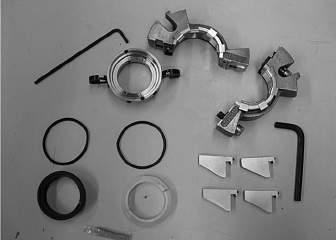
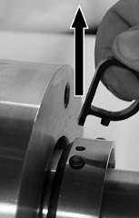
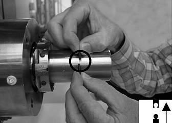
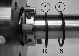
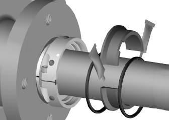
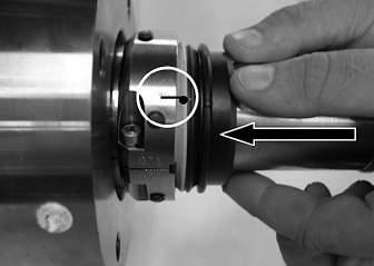
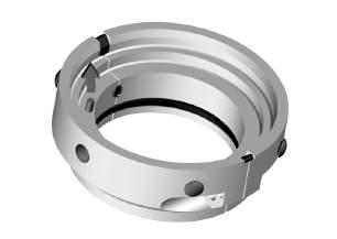
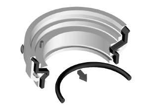
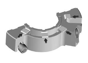
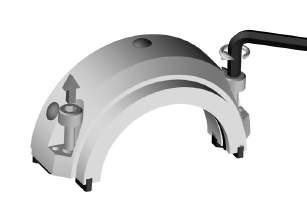
2 SEAL PREPARATION Please read these instructions and make sure you understand them before installing the seal. Installation is easy provided the parts are handled and installed carefully. Make sure your hands are clean. Any dirt particles on the seal faces or splits during handling may cause seal failure. Prepare a clean work surface on which to place parts during assembly/ disassembly. Prepare the Seal for Installation (1-6) 1. Disengage the socket head cap screws from one half of the gland. With the gland in a horizontal position, springs up, separate the halves and place them on the clean work surface. 2. You now have access to the rotary holder. Disengage the two socket head cap screws from one half of the rotary holder and place the holder halves on the clean work surface. 3. Remove the rotary and stationary seal faces from their packages and place on the clean work surface. 4. Make sure that the gland gaskets, holder gaskets, stuffing box gasket (no grease), and shaft O-Ring are properly greased and seated in their grooves. Note the gold mark on one end of each half of the cut shaft O-Ring. Assure that the O-Ring is placed in the rotary holder such that the two gold marks mate at one joint. Do not glue the gland or holder gaskets in place. 5. Snap open the ball and socket joint of the O-Rings by pulling at the seam. (NOTE: The rotary O-Ring is marked with a purple dot.) Do not apply grease or glue to the balls and sockets of the O-Rings. 6. Install seal per instructions (pages 3 and 4). NOTES: The gland, rotary holder, and face halves are matched pairs; mixing components from different seals will result in seal failure. Handle parts carefully. Greasy fingerprints on seal faces or misaligned face splits may cause leakage SCREW AND BOLT TORQUE SEAL SIZE HOLDER CAP SCREWS* GLAND CAP STUFFING BOX (X) SCREWS** (Y) BOLTS** (Z) up to 2.50" 40 in-lbf 43 in-lbf in-lbf ft-lbf (60 mm) (4,5 Nm) (4,8 Nm) (14-20 Nm) (13,5-27 Nm) up to 4.75" 100 in-lbf 110 in-lbf in-lbf ft-lbf (120 mm) (11,3 Nm) (12,4 Nm) (17-23 Nm) (27-34 Nm) up to 7.50" 325 in-lbf 325 in-lbf in-lbf ft-lbf (190 mm) (36,8 Nm) (36,8 Nm) (23-34 Nm) (27-40 Nm) * Recommended maximum. ** Typical values. Torque necessary to seat stuffing box gasket varies with bolt size and gasket sealing surfaces. EQUIPMENT START UP 1. Rotate the shaft by hand to ensure no metal-to-metal contact within the seal. A slight drag may be found due to the seal faces but the shaft should rotate freely. 2. Attach appropriate plumbing to the seal. Take all necessary precautions and follow normal safety procedures before starting the equipment. 3. Depending on how carefully the seal components were handled during installation, split seals may drip on startup. For example, greasy fingerprints on the faces or misaligned face splits may cause leakage. This type of leakage usually decreases Rotary Holder 2. Socket Head Cap Screw (X) 3. Holder Gasket 4. Static O-Ring 5. Rotary O-Ring 6. Rotary Face 7. Stationary Face 8. Stationary O-Ring 9. Gland Gasket 10. Socket Head Cap Screw (Y) 11. Stuffing Box Gasket 12. Anti-Rotation Pin 13. Vacuum Spacer 14. Spring 15. Centering Button 16. Gland 17. Stuffing Box Bolts (Z) 18. Bolt Tabs X-Large only (not shown) and stops over a period of time as a carbon face wears in or leak paths are sealed. However, leakage greater than 60 drops per minute should be investigated immediately. If the leakage remains steady, check O-Rings and gaskets for proper installation and check the faces for chips, scratches, and proper alignment. 2
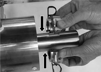
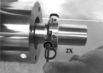
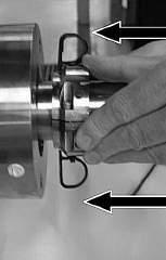
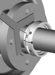
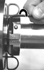
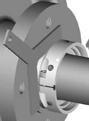
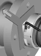
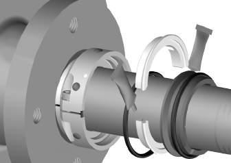
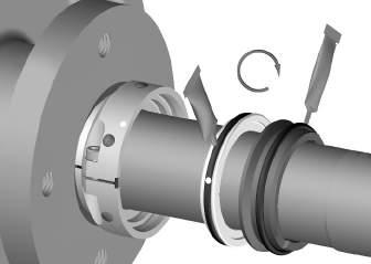
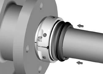
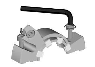
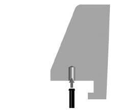
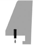
3 INSTALLATION


 Blunt thin lever (remove buttons) Rubber mallet")
 3.")


 (4,8 mm) up to 4 3/4\" 0.290\" (120 mm) (7,4 mm) up to 7 1/2\" 0.")


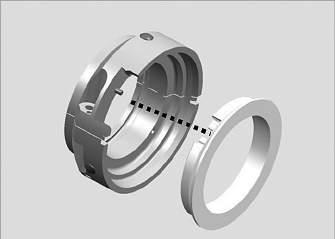
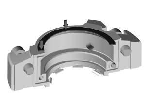
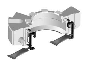
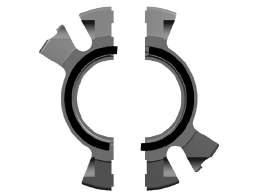
4 INSTALLATION SEAL REBUILD 1. Only the gland and rotary holder are reused. CAUTION: The gland, holder, and face halves are matched pairs; do not mix halves from different seals since this will cause seal failure. 2. The following tools may be required for rebuild: Vice grips (remove drive pin) Arbor press (replace drive pin) Blunt thin lever (remove buttons) Rubber mallet (replace buttons and springs) Channel lock pliers (remove springs) Isopropyl alcohol/actone (clean gasket surface) 3. Disassemble the seal, noting the condition of the parts. Analyze the cause of failure and correct the problem, if possible, before reinstalling the seal. 4. Rebuild of the rotary holder is optional if the shaft O-Ring, holder gaskets and drive pin are in good condition. Seal Drive Pin Size Protrusion up to 2 1/2" 0.188" (60 mm) (4,8 mm) up to 4 3/4" 0.290" (120 mm) (7,4 mm) up to 7 1/2" 0.435" (190 mm) (11 mm) 5. Replacement of springs is optional. Do not replace if springs are in good condition. Ensure all springs are properly seated, and parallel to the back of the gland. 6. Remove the stuffing box gasket from the gland face and remove the adhesive residue with isopropyl alcohol or acetone. After peeling off the protective backing, seat the gasket halves in the gland recess, overlapping the gland splits. Be careful not to wrinkle the gasket as you install it. NOTE: Please see Seal Rebuild images 1 through 18. 4


5 SEAL REBUILD
6 OPERATING CURVES Pressure (PSI) Radial Motion vs. Pressure Capability Shaft Sizes: 1.500" to 2.500" (38 mm to 60 mm) Shaft Runout - TIR (Inches) Pressure (PSI) Radial Motion vs. Pressure Capability Shaft Sizes: 2.625" to 4.750" (65 mm to 120 mm) Shaft Runout - TIR (Inches) Radial Motion vs. Pressure Capability Shaft Sizes: 4.875" to 7.500" (125 mm to 190 mm) Pressure (PSI) Shaft Runout - TIR (Inches) 6
7 DIMENSIONAL DATA (DRAWINGS) Shaft Sizes: 1.500" to 4.750" (38 mm to 120 mm) E N F D M H C A B G 3/8 NPT 2 PLACES O KEY A Shaft Size B Maximum Gland Diameter C Min./Max. Stuffing Box Diameter D Gland Length E Minimum Stuffing Box Depth F Outboard Space Required G Minimum Bolt Circle by Bolt Size H Minimum Stuffing Box Face OD M Holder ID from Box N Installation Dimension O Shaft O-Ring Number 7
8 DIMENSIONAL DATA (INCH) Shaft Sizes: 1.500" to 4.750" A B C D E F G MIN H M N O MAX MIN MAX MIN 3/8" 1/2" 5/8" 3/4" MIN O-RING DIMENSIONAL DATA (METRIC) Shaft Sizes: 38 mm to 120 mm A B C D E F G MIN H M N O MAX MIN MAX MIN 8 mm 10 mm 12 mm 14 mm 16 mm 18 mm MIN O-RING
9 DIMENSIONAL DATA (DRAWINGS) Shaft Sizes: 4.875" to 7.500" (125 mm to 190 mm) E N D F M G L H C A B O 1/2 NPT 2 PLACES KEY A Shaft Size B Maximum Gland Diameter C Min./Max. Stuffing Box Diameter D Gland Length E Minimum Stuffing Box Depth F Outboard Space Required G Minimum Bolt Circle by Bolt Size H Minimum Stuffing Box Face OD L Gland Hub OD M Holder ID from Box N Installation Dimension O Shaft O-Ring Number 9
10 DIMENSIONAL DATA (INCH) Shaft Sizes: 4.875" to 7.500" A B C D E F G MIN H L M N O MAX MIN MAX MIN 5/8" 3/4" 7/8" MIN MAX O-RING DIMENSIONAL DATA (METRIC) Shaft Sizes: 125 mm to 190 mm A B C D E F G MIN H L M N O MAX MIN MAX MIN 18 mm 20 mm 22 mm MIN MAX O-RING
11 11
12 442M is a trademark of A.W. Chesterton Company. DISTRIBUTED BY: Chesterton ISO certificates available on Salem Street Groveland, MA USA Telephone: Fax: A.W. Chesterton Company. Registered trademark owned and licensed by A.W. Chesterton Company in USA and other countries. FORM NO REV. 7 4/16
250L Cartridge Dual Seal
 INSTALLATION, OPERATION AND MAINTENANCE INSTRUCTIONS 250L Cartridge Dual Seal Installation, Operation and Maintenance Instructions TABLE OF CONTENTS 1.0 Cautions...2 2.0 Transport and Storage...2 3.0 Description...2
155 CARTRIDGE SINGLE SEAL
 MECHANICAL SEAL INSTALLATION INSTRUCTIONS 155 CARTRIDGE SINGLE SEAL SEAL INSTALLATION Preparation Determine if the pump is in good condition. A. Check the shaft or sleeve. 1. Remove all burrs and sharp
150 Cartridge Single Seal
 INSTALLATION, OPERATION and MAINTENANCE INSTRUCTIONS 150 Cartridge Single Seal Installation, Operation and Maintenance Instructions TABLE OF CONTENTS 1.0 Cautions... 2 2.0 Transport and Storage... 2 3.0
225 CARTRIDGE DUAL SEAL
 225 CARTRIDGE DUAL SEAL MECHANICAL SEAL INSTALLATION INSTRUCTIONS PREPARATION 1 2 500.010" 0,25 mm 3 4.32 µ" 0,8 µm R a 1000 + ±.001".002" 0,025mm 0,050mm CAUTIONS These instructions are general in nature.
255 Cartridge Dual Seal
 MECHANICAL SEAL INSTALLATION INSTRUCTIONS 255 Cartridge Dual Seal Installation Instructions SEAL INSTALLATION Preparation Determine if the pump is in good condition. A. Check the shaft or sleeve. 1. Remove
250L Dual Cartridge Seal
 INSTALLATION, OPERATION and MAINTENANCE INSTRUCTIONS 250L Dual Cartridge Seal Installation and Operation TABLE OF CONTENTS 1.0 Cautions... 2 2.0 Transport and Storage... 2 3.0 Description... 2 3.1 Parts
280 Heavy Duty Cartridge Dual Seal
 MECHNICL SEL INSTLLTION INSTRUCTIONS 80 Heavy Duty Cartridge Dual Seal SEL INSTLLTION Preparation Determine if the pump is in good condition.. Check the shaft or sleeve. 1. Remove all burrs and sharp corners,
4410 TwinHydrostatic Gas Seal
 IS0 9001 CERTIFIED CHESTERTON FLUID SEALING DIVISION INSTALLATION INSTRUCTIONS 4410 TwinHydrostatic Gas Seal SEAL INSTALLATION Preparation Determine if the pump is in good condition. A. Check the shaft
4400 TwinHybrid Gas Seal
 IS0 14001: 1996 and ISO 9001: 2001 CERTIFIED CHESTERTON FLUID SEALING DIVISION INSTALLATION INSTRUCTIONS 4400 TwinHybrid Gas Seal SEAL INSTALLATION Preparation Determine if the pump is in good condition.
S10/S20 Installation Instructions
 MHNIL SL INSTLLTION INSTRUTIONS S0/S0 Installation Instructions PRPRTION 00.005" 0,3 mm 3 4 3 µ" 0,8 µm Ra 000 ±.00" 0,05 mm UTIONS These instructions are general in nature. It is assumed that the installer
DELTA O-RING CARTRIDGE SEAL ASSEMBLY AND INSTALLATION INSTRUCTIONS INTRODUCTION:
 DELTA O-RING CARTRIDGE SEAL ASSEMBLY AND INSTALLATION INSTRUCTIONS INTRODUCTION: These instructions are provided to familiarize the user with the seal and its use. The instructions must be read carefully
DELTA O-RING CARTRIDGE SEAL ASSEMBLY AND INSTALLATION INSTRUCTIONS INTRODUCTION:
 DELTA O-RING CARTRIDGE SEAL ASSEMBLY AND INSTALLATION INSTRUCTIONS INTRODUCTION: These instructions are provided to familiarize the user with the seal and its use. The instructions must be read carefully
DELTA STYLE 9500 CARTRIDGE SPLIT SEAL INSTALLATION INSTRUCTIONS INTRODUCTION:
 DELTA STYLE 9500 CARTRIDGE SPLIT SEAL INSTALLATION INSTRUCTIONS INTRODUCTION: The Type 9500 Cartridge Split Seal sets the standard in the evolution of split seal designs. It is well suited for the widest
FLUID POWER SEALING SOLUTIONS TROUBLESHOOTING GUIDE
 FLUID POWER SEALING SOLUTIONS TROUBLESHOOTING GUIDE POLYMER SEALS This section provides troubleshooting criteria for Chesterton s hydraulic and pneumatic sealing devices. It should be used only as a general
GAS SEAL ENGINEERED TO BE EASY
 4400 GAS SEAL ENGINEERED TO BE EASY 4400 GAS SEAL Advanced technology made simple Plants are no longer faced with conventional single and dual cartridge seal performance limitations. That s because there
Installation Instructions
 Installation Instructions BW Seals Q, QB Series General Service Balanced Pusher Seal Q, QB, QBQ, QBS, QBU, QBQ LZ Experience In Motion 1 Equipment Check 1.1 Follow plant safety regulations: lock out motor
DELTA O-RING CARTRIDGE SEAL ASSEMBLY AND INSTALLATION INSTRUCTIONS INTRODUCTION:
 DELTA O-RING CARTRIDGE SEAL ASSEMBLY AND INSTALLATION INSTRUCTIONS INTRODUCTION: These instructions are provided to familiarize the user with the seal and its use. The instructions must be read carefully
Installation Instructions
 Installation Instructions Durametallic Double CRO Dual single coil spring friction drive for applications with water lubrication properties 1 Equipment Check 1.1 Follow plant safety regulations prior to
CP-1, CP-2, CP-2L & CPD-2 Series Overhaul
 Replacement of Mechanical Seals for CM, CMU, CS and CSU Series Pumps Installation Instructions Form No. F-1031 Section 5013 Issue Date 03/01/85 Rev. Date 02/08/11 CP-1, CP-2, CP-2L & CPD-2 Series Overhaul
CHESTERTON FLOW GUARDIAN S50 AND SP50 SINGLE FLOWMETER INSTALLATION INSTRUCTIONS
 INSTALLATION INSTRUCTIONS CHESTERTON FLOW GUARDIAN S50 AND SP50 SINGLE FLOWMETER INSTALLATION INSTRUCTIONS GENERAL The function of the FLOW GUARDIAN Single S50 (Item # 199801 compression fitting, 199804
Installation Instructions
 Installation Instructions Single Inside Pusher Type Seals BPO, BPT, BRO, BRT, PTO, PT, RO, RO-TT, and others 1 Equipment Check 1.1 Follow plant safety regulations prior to equipment disassembly: 1.1.1
McCannalok HIGH PERFORMANCE BUTTERFLY VALVE OPERATION AND MAINTENANCE MANUAL. The High Performance Company
 McCannalok HIGH PERFORMANCE BUTTERFLY VALVE OPERATION AND MAINTENANCE MANUAL The High Performance Company Table of Contents Safety Information - Definition of Terms... 1 Introduction... 1 Installation...
S10/S20 Installation Instructions
 ISO 400:996 and ISO 900:000 ERTIFIE MEHNIL SEL INSTLLTION INSTRUTIONS S0/S0 Installation Instructions PREPRTION 00.005" 0,3 mm 3 4 3 µ" 0,8 µm R a 000 ±.00" 0,05mm UTIONS These instructions are general
RDS. Radially Divided Seals.
 RDS Radially Divided Seals Minimum parts to assemble Patented assembled spring retainer External, visible, indicator of correct installation Balanced stationary design with large internal clearances Unique
INSTALLATION, OPERATION & MAINTENANCE GUIDE
 INSTALLATION, OPERATION & MAINTENANCE GUIDE STYLE 23 INTERNATIONAL BRAZIL SOUTHERN USA HEADQUARTERS REPAIR & SERVICE 1 Jackson Street Rua Javaés, 441/443 1719 South Sonny Avenue Essex Junction, VT 05452
Installation Instructions
 Installation Instructions BW Seals RIS Seal Rubber in shear slurry seal Experience In Motion 1 Equipment Check 1.1 Follow plant safety regulations prior to equipment disassembly: lock out motor and valves.
SERVICE INSTRUCTIONS ASSEMBLY & DISASSEMBLY T50X DOUBLE ACTING HYDRAULIC SERIES ACTUATORS
 Page 1 of 7 SERVICE INSTRUCTIONS ASSEMBLY & DISASSEMBLY T50X DOUBLE ACTING HYDRAULIC SERIES ACTUATORS INTRODUCTION This service procedure is offered as a guide to enable general maintenance to be performed
GH-BETTIS OPERATING & MAINTENANCE INSTRUCTIONS DISASSEMBLY & ASSEMBLY FOR THE T80X-M4-S DOUBLE ACTING SERIES HYDRAULIC ACTUATORS
 GH-BETTIS OPERATING & MAINTENANCE INSTRUCTIONS DISASSEMBLY & ASSEMBLY FOR THE T80X-M4-S DOUBLE ACTING SERIES HYDRAULIC ACTUATORS -S INDICATES CYLINDERS ARE IN TANDEM PART NUMBER: 100121 REVISION "A" ECN
HIGH PRESSURE CONTROL VALVE PISTON BALANCED
 PISTON BALANCED All Rights Reserved. All contents of this publication including illustrations are believed to be reliable. And while efforts have been made to ensure their accuracy, they are not to be
Fluid-O-Tech ROTOFLOW ROTARY VANE PUMP REBUILD MANUAL
 Fluid-O-Tech PUMP TECHNOLOGY AT ITS BEST WWW.FLUID-O-TECH.COM Office: 161 Atwater St., Plantsville, CT 06479 Phone: (860) 276-9270 Fax: (860) 620-0193 ROTOFLOW ROTARY VANE PUMP REBUILD MANUAL 08/09 Ed.,
INSTALLATION, OPERATION & MAINTENANCE GUIDE
 INSTALLATION, OPERATION & MAINTENANCE GUIDE SINGLE CARTRIDGE SEAL INTERNATIONAL BRAZIL SOUTHERN USA HEADQUARTERS REPAIR & SERVICE 1 Jackson Street Rua Javaés, 441/443 1719 South Sonny Avenue Essex Junction,
John Crane Type 5620 and 5620PR Dual O-Ring Cartridge Seal Assembly and Installation Instructions
 I-5620/5620PR-A John Crane Type 5620 and 5620PR Dual O-Ring Cartridge Seal Assembly and Installation Instructions Foreword These instructions are provided to familiarize the user with the seal and its
Check valves are for the prevention of backflow. Particular check valves perform additional services as follows:
 KENNEDY VALVE Division of McWane, Inc. 1021 East Water Street P.O. Box 931 Elmira, New York 14902-0931 Telephone (607) 734-2211 Fax (607) 734-1003 KENNEDY VALVE RESILIENT SWING CHECK MAINTENANCE MANUAL
Installation Instructions
 Preparing your vehicle to install your brake system upgrade 1. Rack the vehicle. 2. If you don t have a rack, then you must take extra safety precautions. 3. Choose a firmly packed and level ground to
HYDRAULICS. TX420 & & lower. Hydraulic Tandem Pump Removal. 4. Remove the LH side panel (Fig. 0388).
.") TX420 & 425 240000299 & lower 4. Remove the LH side panel (Fig. 0388). Hydraulic Tandem Pump Removal Note: Cleanliness is a key factor in a successful repair of any hydraulic system. Thoroughly clean all
TX420 & 425 240000299 & lower 4. Remove the LH side panel (Fig. 0388). Hydraulic Tandem Pump Removal Note: Cleanliness is a key factor in a successful repair of any hydraulic system. Thoroughly clean all
A/C COMPRESSOR SERVICING Article Text 1991 Saab 9000 For Copyright 1997 Mitchell International Friday, October 15, :22PM
 Article Text ARTICLE BEGINNING 1991 GENERAL SERVICING Compressor Service * PLEASE READ THIS FIRST * CAUTION: When discharging air conditioning system, use only approved refrigerant recovery/recycling equipment.
INSTALLATION & MAINTENANCE MANUAL
 INSTALLATION & MAINTENANCE MANUAL 3-WAY/4-WAY/5-WAY MULTI-PORT BALL VALVES T TEFLON PARTS - 1. Seat x 5 pcs. 2. Joint Gasket x 5 pcs. 3. Retainer Seal x 5 pcs. 4. Thrust Washer x 1 pc. 5. O-Ring x 1 pc
Upgrade to a new, higher level of reliability and performance. 180 Heavy Duty Cartridge Single Seal
 180 Heavy Duty artridge Single Seal Engineered to defend against common causes of seal failure Full featured PI Gland for complete environmental control capability Patented centering mechanism ensures
3M Overhaul Service Kit
 SERVICE INSTRUCTIONS FOR 3M 12,000 RPM 5 in. (127 mm) and 6 in. (150 mm) RANDOM ORBITAL SANDERS 3M Overhaul Service Kit The part number 20347, 3M Overhaul Service Kit, contains all the replacement parts
I-795/906. Series 795 and 906 Installation-Ready Knife Gate Valves WARNING INSTALLATION AND MAINTENANCE INSTRUCTIONS
 INSTALLATION AND MAINTENANCE INSTRUCTIONS I-795/906 Series 795 and 906 Installation-Ready Knife Gate Valves HANDWHEEL OPERATOR PNEUMATIC OPERATOR HYDRAULIC OPERATOR WARNING Read and understand all instructions
INSTRUCTION MANUAL AND PARTS LIST FOR PG/RG3D_-187, 218, 250 and 312 SERIES PUMPS
 INSTRUCTION MANUAL AND PARTS LIST FOR PG/RG3D_-187, 218, 250 and 312 SERIES PUMPS WARNING This Instruction Manual and General Instructions Manual, CA-1, should be read thoroughly prior to pump installation,
W.S. DARLEY & CO. REPAIR SERVICE INSTRUCTIONS TYPE 1 1/2 AGE PORTABLE PUMP. PUMP DISASSEMBLY FOR OVERHAUL Refer to Drawing DAC0101/DAC0506
 W.S. DARLEY & CO. REPAIR SERVICE INSTRUCTIONS TYPE 1 1/2 AGE PORTABLE PUMP PUMP DISASSEMBLY FOR OVERHAUL Refer to Drawing DAC0101/DAC0506 1. Remove discharge (48) from pump casing (40). Discard gasket/quad
M&H VALVE RESILIENT SWING CHECK MAINTENANCE MANUAL
 M&H Valve Co. Division of McWANE, Inc. 605 West 23 rd Street P.O. Box 2088 Anniston, AL 36202 Telephone (256) 237-3521 Fax (888) 549-5309 M&H VALVE RESILIENT SWING CHECK MAINTENANCE MANUAL I. SELECTION
Installation & Maintenance Manual SPRING ENGAGED FRICTION CLUTCHES THROUGH SHAFT MOUNT - BALL BEARING PILOT REGULAR DUTY
 Installation & Maintenance Manual SPRING ENGAGED FRICTION CLUTCHES THROUGH SHAFT MOUNT - BALL BEARING PILOT REGULAR DUTY Catalog Products: E3A2R-STH E4A2R-STH E5A2R-STH E6A2G-STH And non-catalog variations
LIMITED SLIP DIFFERENTIAL INSTALLATION
 Installation of the limited slip gear can be done with axle out of car or with car lifted to gain access from underneath. Refer to repair manual for proper lifting instructions if car is to be lifted.
W.S. DARLEY & CO. REPAIR SERVICE INSTRUCTIONS TYPE 2 1/2 AGE PORTABLE PUMP PUMP DISASSEMBLY FOR OVERHAUL Refer to Drawing DAC0600
 W.S. DARLEY & CO. REPAIR SERVICE INSTRUCTIONS TYPE 2 1/2 AGE PORTABLE PUMP PUMP DISASSEMBLY FOR OVERHAUL Refer to Drawing DAC0600 1. Remove discharge (73) from pump casing (4). Discard gasket or o ring
OPERATION, MAINTENANCE AND OVERHAUL INSTRUCTIONS FOR PB18 SERIES PORTABLE PUMPS
 WATEROUS COMPANY Form No. F 2058 South St. Paul, Minnesota 55075 January, 1992 OPERATION, MAINTENANCE AND OVERHAUL INSTRUCTIONS FOR PB18 SERIES PORTABLE PUMPS Printed in U.S.A. Waterous Company F 2058
CH-4 Series Fire Pumps Overhaul Instructions
 CH-4 Series Fire Pumps Overhaul Instructions Table of Contents Model CHK-4, Transmission Driven (The pump is turned by a K-Series Transmission mounted directly to the pump.) Introduction... 2 Ordering
Throttling Pendulum Gate O-ring Replacement Procedure Rev. A, May 2012
 Throttling Pendulum Gate O-ring Replacement Procedure Rev. A, May 2012 This procedure covers the replacement of the gate O-ring of the Nor-Cal Pendulum Gate Valve, with the gate valve housing installed
Installation Instructions
 Installation Instructions X-100 Single cartridge mounted welded metal bellows seal Experience In Motion Congratulations You have just purchased a reliable, long-life product manufactured by the leading
FLUID POWER SEALING SOLUTIONS DESIGN GUIDELINES
 FUID POWER SEAING SOUTIONS DESIGN GUIDEINES POYMER SEAS Engineering Guidelines Engineering Introduction Determining the appropriate sealing device for a particular application is generally determined by
Sure Coat 90 Degree Spray Extension
 Instruction Sheet P/N 076A Sure Coat 90 Degree Spray Extension Description The 90 Degree Spray Extension is used on Sure Coat Automatic Powder Spray Guns. It allows powder to be sprayed at right angles
Installation Instructions
 Installation Instructions TM Five Star Seal 80 Series Single, cartridge mounted, flexible stator pusher seal designed for general service applications 84 and 85 Experience In Motion Description The 84/85
John Crane Type 5620 and 5620P Dual O-ring Cartridge Seal Assembly and Installation Instructions
 I-5620/5620P John Crane Type 5620 and 5620P Dual O-ring Cartridge Seal Assembly and Installation Instructions Foreword These instructions are provided to familiarize the user with the seal and its designated
442/489 Series Conversions
 442/489 Series Conversions October 31, 2014 Left Side of Trans. 5 6 Right Side of Trans. 3 4 2 Rules of Conversion 3 Arrangement 5 Arrangement 3 Rules of Conversion 4 Observe and make notes. Observe and
Torque-LOCK TM Static Input Brake Service Manual Models: TLH13.
 Torque-LOCK TM Static Input Brake Service Manual Models: TLH13. Revised 8/18/2014 While every precaution has been taken in the preparation of this document, Fairfield Manufacturing Co. Inc. assumes no
CONTENTS. VIKING PUMP, INC. A Unit of IDEX Corporation Cedar Falls, IA USA SECTION TSM 710.1
 TECHNICAL SERVICE MANUAL industrial heavy duty motor speed pumps SERIES 4076 AND 4176 SIZES hle, ate and ale SECTION TSM 710.1 PAGE 1 of 8 ISSUE B CONTENTS Introduction....................... 1 Safety
TYPE 5625/5625P DUAL METAL BELLOWS CARTRIDGE SEAL
 Foreword TYPE 5625/5625P These instructions are provided to familiarize the user with the seal and its designated use. The instructions must be read and applied whenever work is done on the seal, and must
Installation and Service Instructions. ST Series Pumps
 Installation and Service Instructions ST Series Pumps! WARNING READ MANUAL before operating or working on a Tuthill ST Series pump. Page 2 of 24 4/24/03 Table of Contents Page 4 Page 5 Page 5 Page 6 Page
OWNER S MANUAL. ROTARY SURFACE CLEANER Models 105C, 105F, 105CW, & 105FW. Revision 2.01
 OWNER S MANUAL ROTARY SURFACE CLEANER Models 105C, 105F, 105CW, & 105FW Revision 2.01 ROTARY SURFACE CLEANER WARNING HIGH PRESSURE CAN CAUSE SERIOUS INJURY, MAXIMUM WORKING PRESSURE IS 4000 P.S.I. Any
HYDRAULIC PUMP. INSTALLATION, OPERATION, & MAINTENANCE MANUAL MAINTENANCE MANUAL #: MM-HP Rev. A Page 1 of 12
 INSTALLATION, OPERATION, & #: MM-HP001 4-20-09 Rev. A Page 1 of 12 HYDRAULIC PUMP PART NUMBER HP46982ALSL & HP46982SL HYDRAULIC PUMP MM-HP001 Rev. A Page 2 of 12 Table of Contents 1.0 General Page 3 2.0
CHOOSING THE RIGHT SPLIT CARTRIDGE MECHANICAL SEAL
 CHOOSING THE RIGHT SPLIT CARTRIDGE MECHANICAL SEAL INTRODUCTION Mechanical seals are a common solution for rotating equipment. Once installed, seals are subject to wear, corrosion, vibration, temperature
TYPE 5610V/5610VQ SINGLE O-RING CARTRIDGE SEAL
 1 Foreword These instructions are provided to familiarize the user with the seal and its designated use. The instructions must be read and applied whenever work is done on the seal, and must be kept available
Gear Products Inc N. 161st E. Ave. Tulsa, OK Phone (918) Fax (918)
 Fax (918)") SERVICE MANUAL Disassembly & Assembly Procedures Worm Gear Swing Drive 003 Series Gear Products Inc. 1111 N. 161st E. Ave. Tulsa, OK 74116 Phone (918) 234-3044 Fax (918) 234-3455 Worm Gear Swing Drive
SERVICE MANUAL Disassembly & Assembly Procedures Worm Gear Swing Drive 003 Series Gear Products Inc. 1111 N. 161st E. Ave. Tulsa, OK 74116 Phone (918) 234-3044 Fax (918) 234-3455 Worm Gear Swing Drive
FOR FUTURE REFERENCE SERIES 93HPS
 Hypro Series 93HPS Hydraulically Driven Wetseal Multistage Pumps Repair Manual KEEP FOR FUTURE REFERENCE Form L-1578R Rev. A SERIES 93HPS Hydraulically Driven Stainless Steel Multistage Centrifugal Pumps
OPERATION AND MAINTENANCE INSTRUCTIONS
 OPERATION AND MAINTENANCE INSTRUCTIONS 334 SERIES THREE-PIECE BALL VALVES 1/4 to 2-1/2 Installation and Operation Always install your valve according to accepted industry standards and practices and operate
CP-1, CP-2, CP-2L & CPD-2 Series Overhaul
 CP-1, CP-2, CP-2L, CPD-2, E301-A and E302-A Series Fire Pumps Overhaul Instructions Form No. F-1031 Section 4205.1 Issue Date 02/88 Rev. Date 01/18/08 Table of Contents Safety Information.................................
Boston Gear LOR Series
 Boston Gear LOR Series Trig-O-Matic Lite Overload Release Clutch Installation and Maintenance Instructions Doc. No. LOR Series Trig-O-Matic Lite www.bostongear.com LOR SERIES TRIG-O-MATIC LITE OVERLOAD
READ INSTRUCTIONS COMPLETELY BEFORE BEGINNING INSTALLATION
 INSTALLATION INSTRUCTIONS Hot Fox In-Tank Fuel Warmer READ INSTRUCTIONS COMPLETELY BEFORE BEGINNING INSTALLATION Models covered by these instructions include: HFG 0-0 HFG 0- SHFT--0- SHH--0 TWHF 0- HFG
INSTALLATION, OPERATION & MAINTENANCE GUIDE
 INSTALLATION, OPERATION & MAINTENANCE GUIDE STYLE 58 INTERNATIONAL BRAZIL SOUTHERN USA HEADQUARTERS REPAIR & SERVICE 1 Jackson Street Rua Javaés, 441/443 1719 South Sonny Avenue Essex Junction, VT 05452
REPAIR PROCEDURES MANUAL
 REPAIR PROCEDURES MANUAL PVX Series Vane Pumps A Design Series Step-by-Step Guide to Troubleshooting and Repairing PVX Series Vane Pumps Introduction Thank you for choosing Continental Hydraulics PVX Vane
Models Series Series
 PumpAgents.com - Click here for Pricing/Ordering Models 11860-Series 11870-Series SELF-PRIMING PUMPS ELECTRO-MAGNETIC CLUTCH UNIT FEATURES Body: Impeller: Shaft: Seal: Ports: Bearings: Weight: Bronze Nitrile
INSTALLATION & OPERATING INSTRUCTIONS
 INSTALLATION & OPERATING INSTRUCTIONS WARNING RISK OF ELECTRIC SHOCK. CONNECT ONLY TO A CIRCUIT PROTECTED BY A GROUND-FAULT CIRCUIT-INTERRUPTER. THE UNIT SHOULD BE INSTALLED BY A QUALIFIED SERVICE REPRESENTATIVE.
INSTRUCTION MANUAL IM-422 For HTC/COUPLING ASSEMBLY HC-8088
 No Revision 2/22/18 INSTRUCTION MANUAL IM-422 HTC/COUPLING ASSEMBLY The Riverhawk Company reserves the right to make changes updating this document without dissemination or notice. The latest revision
INSTALLATION INSTRUCTIONS South Highway 11 Westminster, SC Toll Free (888) (864) FAX (864)
 (864) FAX (864)") These instructions apply to the servicing of the Lift Technologies MaxiMizer Integral Sideshifters Cylinder Head. WARNING! Unless the steps in the following Installation Instructions are properly followed
These instructions apply to the servicing of the Lift Technologies MaxiMizer Integral Sideshifters Cylinder Head. WARNING! Unless the steps in the following Installation Instructions are properly followed
TO INDEX DIFFERENTIAL FRONT DIFFERENTIAL CARRIER OIL SEAL (4WD) FRONT DIFFERENTIAL CARRIER ASSEMBLY (4WD) REAR DIFFERENTIAL CARRIER OIL SEAL
 FRONT DIFFERENTIAL CARRIER ASSEMBLY (4WD) REAR DIFFERENTIAL CARRIER OIL SEAL") TO INDEX DRIVE LINE / AXLE DIFFERENTIAL DIFFERENTIAL SYSTEM PRECAUTIONS.............................................. OPERATION CHECK......................................... PROBLEM SYMPTOMS TABLE.................................
TO INDEX DRIVE LINE / AXLE DIFFERENTIAL DIFFERENTIAL SYSTEM PRECAUTIONS.............................................. OPERATION CHECK......................................... PROBLEM SYMPTOMS TABLE.................................
Installation Instructions
 Installation Instructions CPM Series Dual, cartridge mounted, flexible stator pusher seal designed for general service applications CPM PP Experience In Motion Description The CPM PP seal is a cartridge
FUNCTION OF A BEARING
 Bearing FUNCTION OF A BEARING The main function of a rotating shaft is to transmit power from one end of the line to the other. It needs a good support to ensure stability and frictionless rotation. The
Maintenance Information
 80234313 Edition 1 June 2006 Air Grinder, Die Grinder, Sander and Belt Sander Series G1 (Angle) Maintenance Information Save These Instructions WARNING Always wear eye protection when operating or performing
ESM, CSM, CDM, CSWIB, DSWIB mixer cartridge seal ranges
 ESM, CSM, CDM, CSWIB, DSWIB mixer cartridge seal ranges The AESSEAL Group of Companies Designers and Manufacturers of Mechanical Seals and Engineered Seal Support Systems Basic Mixer Cartridge Seal Ranges
SUMMIT PUMP Horizontal End Suction Pump Close Coupled and Frame Mounted
 SUMMIT PUMP Horizontal End Suction Pump Close Coupled and Frame Mounted Installation, Operation, and Maintenance Manual 2014 by Summit Pump, Inc. All rights reserved. WARRANTY Pumping units assembled
3.2 DRIVE TORQUE HUB. Roll, Leak and Brake Testing SECTION 3 - CHASSIS & TURNTABLE. 3-2 JLG Lift
 3.2 DRIVE TORQUE HUB Roll, Leak and Brake Testing 10 LUG PATTERN Torque-Hub units should always be roll and leak tested before disassembly and after assembly to make sure that the unit's gears, bearings
Installation and Operational Instructions for EAS - HTL housed overload clutch Sizes 01 3 Type 490._24.0
 Please read these Operational Instructions carefully and follow them accordingly! Ignoring these Instructions may lead to malfunctions or to clutch failure, resulting in damage to other parts. Contents:
Second Stage Regulator - 1/4 Turn
 Second Stage Regulator - 1/4 Turn MAINTENANCE AND REPAIR TAL 806 (L) Rev. 6 MSA 2008 Prnt. Spec. 10000005389 (I) Mat. 10042827 Doc. 10000015245 1/4 TURN SECOND STAGE REGULATOR SECOND STAGE REGULATOR COMPONENTS
MAINTENANCE AND REPAIR INSTRUCTIONS
 MAINTENANCE AND REPAIR INSTRUCTIONS TYPE TH PUMPS Peerless Pump Company Indianapolis IN, 46207-7026 4849357 TABLE OF CONTENTS Maintenance Page 1 & 2 Disassembly Page 5 & 6 Impeller Clearance 3 Reassembly
Hastelloy is a trademark of Hayes Int l, Inc., Aflas is a trademark of Asashi Glass Co., Ltd.
 ASI Model 730 The ASI Model 730 provides a superior, low-cost alternative to the throw-away seals currently flooding the seal market. The unique split-housing design utilizes a self-contained compact unit
3M Overhaul Service Kit
 SERVICE INSTRUCTIONS FOR 3M 12,000 RPM 3 in. (77 mm) RANDOM ORBITAL SANDERS 3M Overhaul Service Kit The part number 20346, 3M Overhaul Service Kit, contains all the replacement parts that naturally wear
Maintenance Information
 80234313 Edition 2 May 2014 Air Grinder, Die Grinder, Sander and Belt Sander Series G1 (Angle) Maintenance Information Save These Instructions Product Safety Information WARNING Failure to observe the
SKF Flex Coupling Installation Instructions
 SKF Flex Coupling Installation Instructions The performance of the coupling depends largely upon how you install and maintain. 1. Thoroughly clean all components, paying particular attention to the removal
Installation instructions, accessories - Rear Seat Entertainment
 XC90 Section Group Weight(Kg/Pounds) Year Month 3 39 2004 10 XC90 2003, XC90 2004, XC90 2005, XC90 2006, XC90 2007, XC90 2008 Replaces issue: 2003 12 J3904620 Page 1 of 18 Required tools A0000162 A0000163
Maintenance Information
 16573321 Edition 3 February 2014 Air Grinder Series 61H Maintenance Information Save These Instructions Product Safety Information WARNING Failure to observe the following warnings, and to avoid these
Vickers. Overhaul Manual. Vane Pumps. Small and Large Series Combination Pumps VC(K)(S)-**-(*)*D*-6(1) VC(K)(S)-**-(*)-*-*D*-5(1)
(S)-**-(*)*D*-6(1) VC(K)(S)-**-(*)-*-*D*-5(1)") Overhaul Manual Vickers Vane Pumps Small and Large Series Combination Pumps VC(K)(S)-**-(*)*D*-6(1) VC(K)(S)-**-(*)-*-*D*-5(1) Revised 12/1/86 I-3150-S Table of Contents Section I. Introduction................................................................................
Overhaul Manual Vickers Vane Pumps Small and Large Series Combination Pumps VC(K)(S)-**-(*)*D*-6(1) VC(K)(S)-**-(*)-*-*D*-5(1) Revised 12/1/86 I-3150-S Table of Contents Section I. Introduction................................................................................
Maintenance Information
 Form 16573321 Edition 1 July 2004 Air Grinder Series 61H Maintenance Information Save These Instructions Always wear eye protection when operating or performing maintenance on this tool. Always turn off
OWNER S MANUAL EVOLUTION 3500, 4500, 5500, & 8500 SERIES PUMPS
 OWNER S MANUAL EVOLUTION 3500, 4500, 5500, & 8500 SERIES PUMPS IMPORTANT SAFETY INSTRUCTIONS When installing and using this electrical equipment, basic safety precautions should always be followed, including
TECHNICAL SERVICE MANUAL
 Electronic copies of the most current TSM issue can be found on the Viking Pump website at www.vikingpump.com TECHNICAL SERVICE MANUAL industrial heavy duty motor speed pumps SERIES 4076 AND 4176 SIZES
Type 3761 Pneumatic or Electropneumatic Positioner for Rotary Actuators. Fig. 1 Type 3761 Positioner. Mounting and Operating Instructions EB 8386 EN
 Type 3761 Pneumatic or Electropneumatic Positioner for Rotary Actuators Fig. 1 Type 3761 Positioner Mounting and Operating Instructions EB 8386 EN Edition July 2007 Contents Contents Page 1 Design and
TECHNICAL SERVICE MANUAL HEAVY-DUTY BRACKET MOUNTED PUMPS SERIES 120 and SERIES 124 MODELS J, K, KK, L, LQ, LL AND LM
 TECHNICAL SERVICE MANUAL HEAVY-DUTY BRACKET MOUNTED PUMPS SERIES 120 and SERIES 124 MODELS J, K, KK, L, LQ, LL AND LM SECTION 3 BULLETIN TSM-120-124-V ISSUE B-2005 CONTENTS Special Information 2 Maintenance
13. CRANKCASE/CRANKSHAFT/BALANCER/PISTON/CYLINDER
 13. CRANKCASE/CRANKSHAFT/BALANCER/PISTON/CYLINDER COMPONENT LOCATION 13-2 SERVICE INFORMATION 13-3 TROUBLESHOOTING 13-4 CRANKCASE SEPARATION 13-5 CRANKSHAFT 13-7 MAIN JOURNAL BEARING 13-9 CRANKPIN BEARING
INSTRUCTION MANUAL AND PARTS LIST FOR. (A)E3LB(C)(K)-187, -200, and -250 SERIES PUMPS
E3LB(C)(K)-187, -200, and -250 SERIES PUMPS") INSTRUCTION MANUAL AND PARTS LIST FOR (A)E3LB(C)(K)-187, -200, and -250 SERIES PUMPS WARNING This Manual and GENERAL INSTRUCTIONS MANUAL, SRM00046, should be read thoroughly prior to pump installation,
INSTRUCTION MANUAL AND PARTS LIST FOR (A)E3LB(C)(K)-187, -200, and -250 SERIES PUMPS WARNING This Manual and GENERAL INSTRUCTIONS MANUAL, SRM00046, should be read thoroughly prior to pump installation,
TECHNICAL SERVICE MANUAL
 Electronic copies of the most current TSM issue can be found on the Viking Pump website at www.vikingpump.com TECHNICAL SERVICE MANUAL HEAVY-DUTY Stainless steel BRACKET MOUNTED PUMPS SERIES 127 AND 4127