CONTENTS. Introduction Customer Service Product Range Specification and Construction...4-6
|
|
|
- Cleopatra Blake
- 6 years ago
- Views:
Transcription

1
2 CONTENTS PAGE Introduction... 1 Customer Service Product Range... 4 Specification and Construction Salient Features of Ducab s Design... 7 Installation and Electrical Data XLPE Insulated s to BS 5467: Technical Data Tables /1000V rated, Copper and Aluminium Conductors t Single Core s t Two Core s t Three Core s t Four Core s Four Core s with Reduced Neutral Conductors Three and Four Core Armoured s /3300V rated, Armoured Copper Conductors XLPE insulated Lead Sheathed Armoured s to BS XLPE Voltage Drop Data for partial loads Components Reference Chart Ducab is listed in the following publication issued by the Department of Trade and Industry of the United Kingdom. THE DTI QA REGISTER - PRODUCTS AND SERVICES LIST Only those companies whose quality system is assessed and certified by U.K. accredited certification bodies appear in the above publication.
3 INTRODUCTION Established in 1979, Ducab is the leading cable manufacturing company in the region and is equally owned by the Governments of Dubai and Abu Dhabi. Ducab has 3 manufacturing sites and 6 independent manufacturing facilities that support it s continuous growth, one in Jebel Ali and two in Abu Dhabi Industrial City. Ducab-HV, inaugurated in November 2011, is a joint venture between Ducab, ADWEA and DEWA offering High Voltage cable systems up to 400 kv. Ducab-HV will sell cable systems in the voltage range 66kV (66,000 Volts) to 400 kv (400,000 Volts) covering the highest voltage currently used in the GCC. To meet the growing demand of customers around the region and the world, Ducab continues to expand its world-class facilities across the Middle East, North Africa, Europe, Australia and India. Ducab prides itself on setting and maintaining the highest quality standards of power cables. Experienced and highly skilled employees operate state-of-the-art equipment, and conduct extensive testing at every phase of production. When it comes to advanced cable solutions, Ducab continues its status as the superbrand across the world in 40 countries. Ducab product range covers High Voltage cables up to 400 kv, Ducab Powerplus Medium Voltage cables up to 33 kv, Low Voltage power cables, Control & Auxiliary, Wiring and Lead-Sheathed cables, Ducab Smokemaster - Low Smoke Zero Halogen (LSZH) s, THHN/THWN cables, DuFlex cables, Instrumentation and Pilot cables, Flam (Fire Resistant s), components and cable accessories, Installation of cables, as well as Copper rod manufactured in Ducab s own Copper rod plant. This catalogue provides working information on XLPE cables. Separate catalogues are available for the remaining range of Ducab s. Due to the wide range of cables in the catalogue, it is advisable, when ordering, to provide as much information as possible. Please use the following table as a guide: 1. Length of cables required and individual drum lengths.* 2. Voltage designation. 3. Number of cores. 4. Conductor size. 5. Colour of outer sheath. 7. Any other special requirement, e.g. circular conductors, special PVC special material, drum weight limitation etc. ORDERING ADVICE * s are normally supplied in lengths of 100 metres, 500 metres and 1000 metres depending on conductor size. Other lengths can be supplied if required. Please note depending on cable type requirement the ordering advice may change. TECHNICAL ADVISORY SERVICE For any specialist advice and assistance on the entire Ducab product range contact the Technical Department, Dubai Company (Private) Limited, P. O. Box 11529, Dubai, U. A. E., Tel: , Fax:


, Lloyd s Register of the UK, KEMA Netherland, LPCB UK (Loss Prevention")


4 CUSTOMER SERVICE Ducab is the premier cable manufacturer in the United Arab Emirates and, since 1979, has been meeting the requirements of customers throughout the GCC, Middle East and Asian markets. Ducab cables are preferred for the following reasons: Ducab as the premier cable manufacturer in the United Arab Emirates also offer cable application based design solutions, upgrading cable specifications, cable material testing to assess remaining life, as well as Type Testing for customers throughout the GCC and Middle East market. PRODUCT QUALITY Ducab is coitted to supplying its customers with the highest quality of product and of service. Ducab s cables have been type approved by recognized certifying bodies such as BASEC UK (British Approval Service for s), Lloyd s Register of the UK, KEMA Netherland, LPCB UK (Loss Prevention Certification Board), ESMA (Emirates Authority for standardization and Metrology), Kinectrics Nuclear test lab in Canada s fully conform to BS, IEC, NEMA, ASTM, AEIC and other national and international specifications. RELIABILITY Specifying the right cable for a particular application is the first step. The key to reliability however, is in the manufacturing process. The cable must be free from material and manufacturing defects, and weaknesses that will be revealed in service. Ducab constantly monitors its manufacturing processes and operates stringent quality assurance procedures to give long term reliability. Advance test equipment and traceability systems enable Ducab to prevent Counterfeit, Fraudulent and Suspected Items (CFSI). This is of vital significance where cables are to be installed in locations where future access would be difficult and this is where Ducab s reputation and resources give peace of mind. PERFORMANCE Optimum cable performance is provided by Ducab, with access to the latest developments in materials technology. In addition, Ducab s knowledge of the local environment, high ambient temperatures, corrosive soil conditions, and rigorous duty, requirements throughout the Middle East is an assurance for longer life cycle and high performance of cables. Ducab s experienced Technical and R & D Staff provides guidance on cable selection and installation and to ensure the right cable for the application. QUALITY MANAGEMENT SYSTEM CERTIFIED TO ISO 9001 AND NQA1 Ducab s Quality Management System conforms to the ISO 9001 International Quality System Standard and is certified by BASEC (British Approvals Service for s), a specialist certifying body for cables who are an internationally recognised quality authority accredited in the UK and throughout the world. Certification to the ISO 9001 International standard demonstrates that Ducab has drawn up written procedures to ensure full compliance with all requirements of the standard and that these procedures are followed by every department in the company, thus ensuring that goods leaving Ducab s factory are of the highest quality and meet each customer s requirements in every respect. Ducab is particularly proud to have achieved certification to the stringent ISO


 Gold Awards for safety since 1991.")
5 standard as it is an independent conformation that the company designs, manufactures and tests cables consistently to accepted standards. Ducab Quality Management System is also compliant to Nuclear Quality Assurance standard NQA 1 which is applied to safety critical products to Nuclear Industry ENVIRONMENTAL MANAGEMENT SYSTEM CERTIFIED TO ISO Ducab s Environmental Management System conforms to the ISO International Environmental Management Standard and is certified by BASEC who are an internationally recognised certifying authority accredited in the UK and throughout Europe. Certification to the ISO International standard shows that Ducab has a well defined structure and established working practices aimed at limiting its impact on the environment. Measurement and monitoring of effects, issuing work instructions, training of personnel and taking corrective actions are all essential elements to limiting the impact on the environment. Ducab has set improvement targets to reduce the significant environmental impacts associated with its activities. Ducab is proud to be the first cable manufacturer in the region to achieve certification to ISO and this certification along with its quality, business success and safety record demonstrates that Ducab is a world class organisation and can hold its head up to any business counity throughout the world. HEALTH & SAFETY MANAGEMENT SYSTEM CERTIFIED TO OHSAS Ducab is able to maintain a close watch on world developments in cable technology and regulations and therefore ensure that its products are designed and constructed to be hazard-free under the prescribed conditions of use. Ducab uses only tried and tested materials and processes in full compliance with all relevant British and International Standards. Our cables are therefore manufactured for safe use without risk to health on the understanding that users will exercise the same degree of care in their selection and application. Safety is an important issue for Ducab, and the stringent standards are adhered to throughout the company. Ducab is proud of its safety record and has been awarded RoSPA (Royal Society for the Prevention of Accidents) Gold Awards for safety since From 2000 onward, Ducab was awarded the prestigious President s Award for Health and Safety which is a recognition of Ducab winning 10 consecutive annual Gold awards and acknowledges Ducab s total coitment to health and safety. In 2002, Ducab was declared the joint winner of the Manufacturing Industry Sector Award from RoSPA. DUCAB SHAREEK Ducab s customer satisfaction prograe is designed to ensure that customers receive a consistently high level of service from Ducab s dedicated staff. APPROVAL CERTIFICATES 3
6 Voltage range: 0.6/1kV and 1.9/3.3 kv Types PRODUCT RANGE 1) Armoured/unarmoured XLPE insulated cables 2) Lead sheathed cables 3) Copper or Aluminium PE tape (with drain wire) shielded sizes Single core up to and including core up to and including core up to and including core up to and including core up to and including 95 2 Specification BS for XLPE insulated armoured cables BS for XLPE insulated single core unarmoured cables IEC (Part 1)...for XLPE insulated single/multicore armoured/unarmoured cables Any other International Specification as per VDE/DIN, GOST and as per customer s specifications. SPECIFICATION AND CONSTRUCTION CONDUCTORS It is the current carrying component of the cable. Material: Plain, stranded, compacted copper as per IEC: Aluminium, stranded, compacted conductors INSULATION The rated voltage level of the cable depends on the dielectric strength and thickness of the insulation. Material: Cross-linked polyethylene (XLPE) Type GP8 as per BS 7655:Section 1.3. Colour Masterbatch Ultra-violet (UV) resistant polyethylene masterbatch is used for colouring of insulation. This protects the insulation from deterioration when exposed to continuous sunlight. 4
7 CORE IDENTIFICATION Core identification is by colour as follows (unless otherwise agreed): 1 core 2 core Red Black 3 core Red Yellow Blue 4 core Red Yellow Blue Black 5 core Red Yellow Blue Black Green/Yellow * s to new colour scheme of BS 5467 eg. Blue, Brown, Black, Grey could also be supplied on special request FILLERS For providing circular shape to the cable, non-hygroscopic compatible fillers (wherever necessary) are included between laid up cores. Metallic Screen If required by the customer screening may be provided for electrical shielding. Material Copper tape / Copper laminate / Aluminium laminate Aluminium PE tape along with tinned copper drain wire (for providing screen continuity). Note: Special constructions other than stated above may be provided on request. Barrier Tape Material Polypropylene/PETP tape is used as a barrier tape over the laid up cores. Functions Holds the cores together and prevents them from opening out. Works as a separator between different polymers used in a cable. BEDDING Extruded bedding serves as a bedding for the armour and as a protection for the laid-up cores. Material Extruded PVC Type 9 Compound as per BS Reduced propagation flame retardant (RPLHCL)/RP PVC Compound for reduced flame propagation characteristics. Smokemaster Low smoke and Zero Hallogen for installations where fire hazards exist. 5
8 ARMOUR Armour provides mechanical protection to the cable. It also serves as an Earth Continuity Conductor (ECC). One layer of round wire is applied helically over the bedding. Material Galvanised round steel wire (GSW). Galvanised round steel wire (GSW) along with tinned copper wires (TCW) for maintaining specified conductivity of armour (if required by the customer). Aluminium round wire armour (AWA) is generally used for single core ac circuits as aluminium is a nonmagnetic material and this will reduce losses due to armour. Note: Aluminium glands should be used in conjunction with cables having aluminium wire armour. OVERSHEATH - FINISH Following types of materials may be specified for oversheathing. General Purpose: Extruded PVC Type 9 Compound as per BS Medium Density Polythylene (MDPE): Offers higher protection from water ingress and mechanical abrasion. Anti Termite: Termite resistance can be built in both types described above by compounding with proper additives. Reduced Propagation (RP): Retards propagation of flame in fire situation. (Oxygen Index 30) Reduced Propagation and Low Acid Fumes (RPLHCL): Retards propagation of flames and gives low emission of hydrochloric acid fumes. (OI 30 & acid gas emission is less than 18%) 6
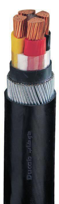
9 SALIENT FEATURES OF DUCAB CABLE DESIGN (1) XLPE insulation Ultra-violet (UV) colour masterbatch Ultra-violet (UV) resistant polyethylene masterbatch is used for colouring of insulation. This protects the insulation from deterioration when exposed to continuous sunlight. (2) Polypropylene/PETP tape over the laid up cores Acts as a separator between different polymers used in a cable. (3) Fillers For ensuring proper circular shape to the cable, non-hygroscopic compatible fillers (wherever necessary) are included between laid up cores. (4) Special requirements Ducab cables can be custom designed to incorporate special requirements of the client as follows: (a) Screening: Copper tape or Aluminium PE tape (along with tinned copper drain wire) can be used for shielding purposes. (b) Tinned copper wire can be used along with galvanised round steel wires to maintain specified armour conductivity requirements. (c) Reduced propagating flame retardant bedding (RPLHCL/RP) and outersheath material can be offered to meet reduced flame propagation characteristics and low hydrogen acid gas emission. (d) with bedding and outersheath material of special LSZH (Low Smoke and Zero Halogen) compound can be offered for installations where fire and its associated problems - the emission of smoke and toxic fumes - offer a serious potential threat. (For details on LSZH cables refer page 33-34) (e) In water logged areas or where the cables are required to be abrasion resistant, cable with medium density polyethylene (MDPE) can be offered. (f) For protection from insects, anti-termite protection can be added to the outersheath. (5) Fire test requirement s sheathed with general purpose PVC Type 9 meet fire test requirement of IEC s with varying fire performance requirements are manufactured by Ducab. The details on this are provided on request. INSTALLATION Whichever form of conductor is used, XLPE insulated cables are simple to handle, install and joint. All the cables described in this publication can be used indoors or outdoors, but some reservations are necessary concerning cables for direct burial in the ground or for use in sustained wet conditions as follows: (i) Unarmoured cables are not generally recoended for laying directly in the ground. (ii) s laid directly in the ground, particularly in sustained wet conditions, should have extruded bedding and preferably MDPE - Medium Density Polyethylene - as the outersheath material. Other important factors to be taken into account are: 7
10 Sheath Damage Care should be taken to ensure that the oversheath is not damaged during installation. This is especially important where aluminium wire armour is used, as ingress of moisture could lead to corrosion or ultimate loss of earth continuity. Minimum Installation Radius should not be bent during installation to a radius smaller than that recoended below. Wherever possible larger installation radii should be used. Overall Diameter (D) Minimum internal radius of bend Circular copper conductors armoured or unarmoured Any 6D Shaped copper or aluminium conductors, armoured or unarmoured Any 8D For lead sheathed cables Any 12D Connectors The use of compression type connectors is recoended for XLPE insulated cables since the use of soldered connectors would limit the maximum short circuit temperature of the cable to 160 C (and consequently reduce the final short circuit current by approximately 30%). Overhead terminations Ultra violet resistant sleeving or taping should be provided on XLPE insulated cores to avoid degradation due to exposure to solar rays. Armoured Single Core s for AC Operation The current rating provided for single core cables is based on armour bonded / earthed at both ends. Armour bonding at both ends results in circulating current in the armour. Higher current rating may be achieved in case the armour is bonded / earthed at single end. However single end bonding results in an induced voltage at the unearthed end of the armour. The magnitude of induced voltage is directly proportional to the current through the conductor and length of the cable. At times the magitude of induced voltage could pose potential risk if no limiting device is connected at the open end. For this purpose sheath voltage limiters are in use. Ducab strongly recoends use of an insulated adopter in the cable gland, while terminating single core cables for AC operation. Single core cables for AC operation should not pass through steel conduit or steel gland plate, as it produces a heating effect. CABLE SUPPORT SPACING As per IEE Wiring Regulations where the cable is not continuously supported it shall be supported by suitable means at appropriate intervals in such a manner that the cable does not suffer damage by its own weight. CURRENT RATINGS Current ratings for XLPE insulated cables for ground and duct installation are derived from the latest issue of ERA Report Part 5 which is based upon IEC Publication The ratings for In Air installation are taken from IEE Wiring Regulations. 8
11 All the ratings given are for single circuits installed thermally independent of other circuits or any other heat source and on the basis of the standard conditions of installation given in relevant Tables. For other ambient or ground temperatures, depth of laying, soil thermal resistivity, the rating must be multiplied by relevant rating factors in Tables. It should be noted that if XLPE insulated cables, are subjected to operating temperatures appreciably higher than the 90 C permissible for continuous operation, the insulation will undergo premature ageing thus affecting the normal life of the cable. However, limiting maximum conductor temperature to 105 C during overloads with duration not exceeding 4 hours on any one occasion, or a maximum of 100 hours in any 12 consecutive months, or a total of 500 hours in the cable s lifetime, would be tenable. IEE WIRING REGULATIONS - REQUIREMENT FOR CABLES The IEE Wiring Regulations for installation and selection of cables cannot be approached in isolation from the other equipment in the installation. In particular the devices providing protection against overload, short circuit, shock by indirect contact and over-heating of protective conductors during an earth fault, affect the selection of cables. CROSS SECTIONAL AREAS OF PROTECTIVE CONDUCTORS (Clause 543 of the 16th Edition of IEE Wiring Regulations) Regulation 543 explains how the cross sectional area of the circuit protective conductor should be calculated to avoid it over-heating during a fault to earth. Again the area required depends on the characteristics of the device providing protection against short circuit. The steel wire armour of standard cables to BS 5467 (XLPE) and BS 6346 (PVC) provides the required area, or more, when the protective device is one of the standard fuses or MCB s with a rating not higher than the current rating of the cable (assuming disconnection within 5 seconds). For the most of the cables the armour is still adequate when the fuse rating is one or two steps, or even more, above the current rating of the cable, the margins being greater for the small sizes and 4 core cables than for the larger sizes and two core cables. VOLTAGE DROP Voltage drop is normally only of importance for cables of voltage rating 600/1000V or below. If the installation is to be incompliance with Regulation 525 of the 16th Edition of the IEE Wiring Regulations, it is stipulated that the voltage drop within the installation does not exceed a value appropriate to the safe functioning of the associated equipment in normal service. The requirement is deemed to be satisfied if the drop in voltage from the origin of the installation (usually supply terminals) and the fixed current using equipment does not exceed 4 per cent of the nominal voltage of the supply, disregarding starting conditions. (Note: Diversity can be taken into account when calculating voltage drop). Since the actual power factor of the load is often not known, the most practical approach to the question of voltage drop is to assume the worst conditions i.e. where the phase angle of the load is equal to that of the cable. The voltage drop values in the tables have been based on this assumption. For conductor sizes up to and including the figures provided apply with sufficient accuracy where the power factor lies between 0.6 lagging and 1.0, and for large cables where the power factor of the load does not exceed 0.8 lagging. Where the phase angles of the loads fall outside this range, the voltage drop deduced from the tables may be unduly conservative and more exact methods of calculation should be employed. 9
12 The values of voltage drop for 600/1000 V rated cables are given in the current rating tables. In those cases where the actual current differs greatly from the tabulated current rating, the results obtained from the tables are only approximate; for a more accurate assessment, allowance should be made for the change in conductor resistance with operating temperature. It should also be ensured that the cable size ultimately selected is capable of carrying the required current under the site conditions of installation. Values of voltage drop are tabulated for a current of one ampere for a 1 metre run, i.e. for a distance of 1 metre along the route taken by the cables, and represent the effect of the voltage drop in all the circuit conductors. For balanced three phase ac circuits, the values relate to the line voltage. For any given run the values need to be multiplied by the length of the run (in metres) and by the current (in amperes) that the cables are to carry. Examples: Consider a route of 200 metres of 4 Core armoured cable to be installed in air and to carry 100 amperes load per phase, with the supply voltage being 415 volts, three phase 50 Hz and the cable to be Copper XLPE/SWA/ PVC. Using the Tables: Let Vd be the voltage drop in volts. where I = Current in amperes L = Route length in metres = Approximate volt drop/ampere/metre Assume maximum permissible volt drop = 4 per cent of 415 volts = 16.6 volts Substitute for current, route length and maximum permissible volt drop then Vd = x I x L 1000 or = Vd x 1000 I x L = 16.6 x x 100 = 0.83 Select a cable from the relevant Current Rating Table 26 such that the value from the voltage drop column is equal to or less than the 0.83 calculated, ensuring that it will carry the current. It will be seen that this value is 0.6 giving a cable size of However, 100 Amp load could be less than 80% current carrying capacity of 50 2 cable, in which case of 50 2 cable will suffice. 10
13 RATING FACTORS Where the conditions of installation differ from those defined in the current rating tables, the following rating factors may be used for cables size selection. (Reference ERA report) CABLES LAID DIRECTLY IN GROUND Ratings for cables installed directly in the ground are based on values of soil temperature and soil thermal resistivity which are generally representative of conditions in the United Kingdom. Rating factors to take account of variation in ground temperatures are given in Table 2. Where conditions of operation can be fairly accurately estimated and knowledge of the soil along the route is available, it is possible to determine the ratings more precisely by the use of the soil thermal resistivity factors, grouping factors, and factors for the depths of laying given in Tables 3 to 6. RATING FACTORS FOR GROUND TEMPERATURE Ground temperature 15 C 20 C 25 C 30 C 35 C 40 C 45 C Type Rating factor XLPE Insulated RATING FACTORS FOR VARIATION IN THERMAL RESISTIVITY OF SOIL (AVERAGE VALUES) Size of cables 2 Soil thermal resistivity in C m/w Single core cables Up to From 185 to From 400 to Multicore cables Up to From 25 to From 185 to
14 RATING FACTORS FOR DEPTH OF LAYING (TO CENTRE OF CABLE OR TREFOIL GROUP OF CABLES) Depth of laying m 600/1000 Volt 1900/3300 Volt Up to to Above Up to Above or more GROUP RATING FACTORS FOR CIRCUITS OF THREE SINGLE CORE CABLES IN TREFOIL OR LAID FLAT TOUCHING, IN HORIZONTAL FORMATION Number of Circuits Spacing Spacing Spacing of Circuits Touching** Trefoil Laid flat 0.15 m* 0.30 m 0.45 m 0.60 m /1000 Volt cables / Volt cables * This spacing will not be possible for some of the larger diameter cables. ** For high current carrying cables (i.e. large size) it is advisable to allow spacing between circuits. Alternatively the most appropriate group rating factor must be applied when determining the cable size and required number of cables in parallel. 12
15 GROUP RATING FACTORS FOR MULTICORE CABLES IN HORIZONTAL FORMATION Number of s in Group Spacing Spacing 600/1000 Volt cables 1900/3300 Volt cables Touching** 0.15 m* 0.30 m 0.45 m 0.60 m * For high current carrying cables (i.e. large size) it is advisable to allow spacing between circuits. Alternatively the most appropriate group rating factor must be applied when determining the cable size and required number of cables in parallel. CABLES INSTALLED IN DUCTS The term ducts applies to single way earthenware, fibre or ferrous pipes. RECOMMENDED DUCT DIMENSIONS AND CABLE SIZES Duct Overall cable diameter Inside diameter Outside diameter Up to and including Above 65 up to and including Ratings for cables installed in single way ducts, underground, have been based on values of soil temperature and soil thermal resistivity which are generally representative of conditions in the United Kingdom. Rating factors to take account of variations in ground temperatures are given in Table 2. Where conditions of operation can be fairly accurately estimated, and knowledge of the soil along the route is available, it is possible to determine the ratings more precisely by the use of estimated maximum ground temperature, the soil thermal resistivity factors, grouping factors, and factors for the depths of laying given. RATING FACTORS FOR GROUND TEMPERATURE Note: Same as for direct in ground. 13
16 RATING FACTORS OF VARIATION IN THERMAL RESISTIVITY OF SOIL (AVERAGE VALUES) Soil thermal resistivity in C m/w Size of cable Single Core Up to From 185 to From 400 to Multicore s Up to From 25 to From 185 to RATING FACTORS OF DEPTH OF LAYING (TO CENTRE OF DUCT OR TREFOIL GROUP OF DUCTS) Depth in laying m 600/1000 Volt 1900/3300 Volt Single Core Multicore Single Core Multicore or more GROUP RATING FACTORS FOR SINGLE CORE CABLES IN TREFOIL SINGLE WAY DUCTS, HORIZONTAL FORMATION (AVERAGE VALUES) Number of Circuits Spacing Spacing Touching* 0.45 m 0.60 m / Volt s / Volt s * For high current carrying cables (i.e. large size) it is advisable to allow spacing between circuits. Alternatively the most appropriate group rating factor must be applied when determining the cable size and required number of cables in parallel. 14
17 GROUP RATING FACTORS FOR MULTICORE CABLES IN SINGLE WAY DUCTS, HORIZONTAL FORMATION (AVERAGE VALUES) Number of Circuits Spacing Touching* 0.30 m 0.45 m 0.60 m / Volt s / Volt s * For high current carrying cables (i.e. large size) it is advisable to allow spacing between circuits. Alternatively the most appropriate group rating factor must be applied when determining the cable size and required number of cables in parallel. CABLES INSTALLED IN AIR It is anticipated that many of the in air installations will be in buildings, and the ratings are therefore given in accordance with IEE Wiring Regulations for Electrical Installations, 16th Edition. It should be noted that all ratings for cables run in free air have been based on the assumption that they are shielded from the direct rays of the sun without restriction of ventilation. The rating for cables subjected to direct sunlight should be reduced to take account of this factor and further guidance on this subject is available on request. RATING FACTORS FOR OTHER AMBIENT AIR TEMPERATURES Air Temperature 25 C 30 C 35 C 40 C 45 C 50 C 55 C XLPE Insulated DEFINED CONDITIONS OF INSTALLATION Spacing The in-air current ratings given in relevant Tables between 18 to 34 are based on the installation conditions in air as follows: (a) Single core cables (1) Two single core cables are installed one above the other, fixed to the vertical surface of a wall or open cable trench, the distance between the wall and the surface of the cable being not less than 20. s are installed at a distance between centres of twice the overall diameter of the cable, i.e. 2D, where D = overall diameter of cable. (2) Three single core cables are installed in trefoil formation, fixed to the vertical surface of a wall or open cable trench, the cables touching throughout and the distance between the wall and the surface of the nearest cable being not less than 20. The cables are assumed 15
18 to be remote from iron, steel or ferro-concrete, other than the cable supports. Single core armoured cables to be electrically bonded at each end of the run. (b) Multicore s s of all types other than single core cables are installed singly, fixed to the vertical surface of a wall or open cable trench, the distance between the surface of the cable and the wall being not less than 20 in every instance. If it is necessary for cables to be installed at distances less than those described above, then the values tabulated under the heading Clipped direct to a surface... in the IEE Wiring Regulations should be employed. SHORT CIRCUIT RATINGS CONDUCTORS Short circuit ratings for 1 second in KA Conductor size 2 Copper Conductor Aluminium Conductor Note: For any other duration t seconds divide the given value by t The values of fault current given in the graph are based on the cable being fully loaded at the start of the short circuit (conductor temperature 90 C) and a final conductor temperature of 250 C. It should be ensured that the accessories associated with the cables are also capable of operation at these values of fault current and temperature. Note: With XLPE cables the use of soldered type connectors (instead of the compression type) is not recoended since their use in the system would limit the final conductor temperature to 160 C (and consequently reduce the fault current rating by approximately 30 per cent). 16
19 Copper Conductors FAULT CURRENT KILOAMPERES DURATION OF SHORT CIRCUT IN SECONDS FAULT CURRENT KILOAMPERES Aluminium Conductors DURATION OF SHORT CIRCUT IN SECONDS 17
20 Nominal Area of Conductor 2 SHORT CIRCUIT RATINGS ARMOUR XLPE INSULATED CABLES ARMOUR FAULT CURRENTS TO EARTH (FOR A FAULT DURATION OF 1 SECOND) Aluminium Wire Armour Steel Wire Armour 600/1000 V 1900/3300 V 600/1000 V 1900/3300 V Four Core Single Core Single Core Two Core Three Core Four Core (reduced amp amp amp amp amp neutral) amp Three Core amp XLPE XLPE XLPE XLPE XLPE XLPE XLPE * 4700* * 5200* * 5700* * * Based on wire diameters larger than those specified in BS Notes: 1. The ratings given in the Table above are based on a fault duration of one second and an armour temperature rise from 80 C at coencement of the fault to a final temperature of 200 C. 2. The asyetrical fault rating of the smaller sizes may be decided by the short circuit capability of the conductor rather than the armour rating. It is therefore necessary to compare the two ratings. 18
21 CONDUCTOR / ARMOUR RESISTANCE AND REACTANCE VALUES 600/1000 V SINGLE AND MULTICORE CABLES HAVING WIRE ARMOUR Nominal Area of Conductor 2 Copper Conductor Aluminium Conductor Maximum resistance of - Armour in ohms/km at 20 C Single Core Two core Three Core Four Core** (equal neutral) Four Core (reduced neutral) Aluminium wire armour With stranded copper conductor & Galvanised Steel Wire Armour With stranded copper conductor 600/1000 V With stranded aluminium conductor 600/1000 V 600/ 1000 V 600/ 1000 V 1900/ 3300 V 600/ 1000 V 600/ 1000 V Inductive reactance (approx) per core of 3 phase circuite in 50 Hz Single core cable Two core cable Three & Four core cable * The values given are for plain annealed copper conductors. For tinned conductors reference should be made to BS ** Multicore cables with stranded Aluminium conductor have same Armour resistances as those with Copper conductors. 19
22 XLPE INSULATED CABLES TO BS 5467 & IEC DIMENSIONS AND WEIGHTS STRANDED COPPER & ALUMINIUM CONDUCTORS SINGLE CORE CABLES 600/1000 V *UNARMOURED AND ARMOURED, PVC SHEATHED CABLES Nominal Thickness area of of conductor insulation 2 Unarmoured s Armoured s (approximate values) (approximate values) Diameter weight weight under diameter Aluminium Copper kg/ armour overall kg/km km Armour** wire weight weight diameter diameter Aluminium Copper kg/ overall kg/km km *** *** *** *** * Single core unarmoured cables are as per BS ** Aluminium wire armour for AC system. *** Wire diameters are larger than those specified in BS Note: s with Stranded Aluminium Conductors conform to IEC
23 CURRENT RATINGS (AC) STRANDED COPPER & ALUMINIUM CONDUCTORS SINGLE CORE CABLES 600/1000 V ARMOURED PVC SHEATHED CABLES Stranded Copper Conductors Approximate voltage drop Current Ratings per ampere per metre Stranded Aluminium Conductors Approximate voltage drop Current Ratings per ampere per metre Nominal area of conductor 2 Direct in ground In single way ducts 3D Installed in air Ground Duct Air Direct in ground In single way ducts 3D Installed in air Ground Duct Air 600/1000 V UNARMOURED PVC SHEATHED CABLES Stranded Copper Conductors Current Ratings Approximate voltage drop per ampere per metre Stranded Aluminium Conductors Current Ratings Approximate voltage drop per ampere per metre Nominal area of conductor 2 Direct in ground In single way ducts 3D Installed in air Ground Duct Air Direct in ground In single way ducts 3D Installed in air Ground Duct Air Direct in ground - Trefoil touching Single way ducts - ducts touching Spacing in air - As shown above (D = diameter) Non magnetic wire armour bonded at both ends Installation conditions for above ratings: Ambient air temperature: 30 C Depth of laying:0.5 m Soil thermal resistivity: 1.2 C m/w Maximum conductor operating temperature at rated current is 90 C For rating factors see Tables 2 to 6 and 8 to 12 21
24 XLPE INSULATED CABLES TO BS 5467 & IEC DIMENSIONS AND WEIGHTS STRANDED COPPER & ALUMINIUM CONDUCTORS TWO CORE CABLES 600/1000 V *UNARMOURED AND ARMOURED, PVC SHEATHED CABLES Nominal Thickness area of of conductor insulation 2 Unarmoured s Armoured s (approximate values) (approximate values) diameter overall weight Aluminium kg/km weight Copper kg/km Diameter under armour Armour** wire diameter diameter overall weight weight Aluminium Copper kg/km kg/km 16* * * * Circular conductor, all others are sector shaped. Note: Unarmoured cables & cables with Stranded Aluminium Conductors conform to IEC
25 CURRENT RATINGS (AC) STRANDED COPPER & ALUMINIUM CONDUCTORS TWO CORE CABLES 600/1000 V ARMOURED PVC SHEATHED CABLES Nominal area of conductor 2 Direct in ground Stranded Copper Conductors Approximate voltage drop Current Ratings per ampere per metre In single way ducts Installed in air Ground Duct Air Direct in ground Aluminium Conductors Approximate voltage drop Current Ratings per ampere per metre In single way ducts Installed in air Ground 16* * * * Circular conductor, all others are sector shaped Duct Air 600/1000 V UNARMOURED PVC SHEATHED CABLES Nominal area of conductor 2 Direct in ground Stranded Copper Conductors Current Ratings In single way ducts Installed in air Approximate voltage drop per ampere per metre Ground Duct Air Direct in ground Current Ratings In single way ducts Aluminium Conductors Installed in air Approximate voltage drop per ampere per metre Ground 16* * * Duct Air Direct in ground - s touching Single way ducts - ducts touching * Circular conductors, all others are sector shaped Note: (1) 50 2 and above are with D-shaped conductor (2) Unarmoured cables are as per IEC Installation conditions for above ratings: Ambient air temperature:30 C Ground temperature: 15 C, Depth of laying: 0.5 m Soil thermal resistivity: 1.2 C m/w Maximum conductor operating temperature at rated current is 90 C For rating factors see Tables 2 to 6 and 8 to 12 23
26 XLPE INSULATED CABLES TO BS 5467 & IEC DIMENSIONS AND WEIGHTS STRANDED COPPER & ALUMINIUM CONDUCTORS THREE CORE CABLES 600/1000 V *UNARMOURED AND ARMOURED, PVC SHEATHED CABLES Nominal Thickness area of of conductor insulation 2 Unarmoured s Armoured s (approximate values) (approximate values) diameter overall weight Aluminium kg/km weight Copper kg/km Diameter under armour Armour** wire diameter diameter overall weight weight Aluminium Copper kg/km kg/km 16* * * * Circular conductors, all others are sector shaped. Note: Unarmoured cables & cables with Stranded Aluminium Conductors conform to IEC
27 CURRENT RATINGS (AC) STRANDED COPPER & ALUMINIUM CONDUCTORS THREE CORE CABLES 600/1000 V ARMOURED PVC SHEATHED CABLES Nominal area of conductor 2 Direct in ground Stranded Copper Conductors Approximate voltage drop Current Ratings per ampere per metre In single way ducts Installed in air Ground Duct Air Direct in ground Aluminium Conductors Approximate voltage drop Current Ratings per ampere per metre In single way ducts Installed in air Ground Duct Air 600/1000 V UNARMOURED PVC SHEATHED CABLES Nominal area of conductor 2 Direct in ground Stranded Copper Conductors Current Ratings In single way ducts Installed in air Approximate voltage drop per ampere per metre Ground Duct Air Direct in ground Current Ratings In single way ducts Aluminium Conductors Installed in air Approximate voltage drop per ampere per metre Ground Duct Air Direct in ground - s touching Single way ducts - ducts touching * Circular conductors, all others are sector shaped Note: Unarmoured cables are as per IEC Installation conditions for above ratings: Ambient air temperature:30 C Ground temperature: 15 C, Depth of laying:0.5 m Soil thermal resistivity: 1.2 C m/w Maximum conductor operating temperature at rated current is 90 C For rating factors see Tables 2 to 6 and 8 to 12 25
 weight Aluminium kg/km weight Copper kg/km Diameter under armour Armoured s (approximate values) Armour**")
28 XLPE INSULATED CABLES TO BS 5467 & IEC DIMENSIONS AND WEIGHTS STRANDED COPPER & ALUMINIUM CONDUCTORS FOUR CORE CABLES 600/1000 V *UNARMOURED AND ARMOURED, PVC SHEATHED CABLES Nominal area of conductor 2 Thickness of insulation diameter overall Unarmoured s (approximate values) weight Aluminium kg/km weight Copper kg/km Diameter under armour Armoured s (approximate values) Armour** wire diameter diameter overall weight Aluminium kg/km 16* weight Copper ** * Circular conductors, all others are sector shaped. ** as per IEC Note:Unarmoured cables & cables with Stranded Aluminium Conductors conform to IEC kg/km 26
29 600/1000 V UNARMOURED PVC SHEATHED CABLES Nominal area of conductor 2 Direct in ground Stranded Copper Conductors Current Ratings In single way ducts Installed in air CURRENT RATINGS (AC) STRANDED COPPER & ALUMINIUM CONDUCTORS FOUR CORE CABLES 600/1000 V ARMOURED PVC SHEATHED CABLES Nominal area of conductor 2 Direct in ground Stranded Copper Conductors Approximate voltage drop Current Ratings per ampere per metre In single way ducts Installed in air Ground Approximate voltage drop per ampere per metre Ground Duct Duct Air Air Direct in ground Direct in ground Aluminium Conductors Approximate voltage drop Current Ratings per ampere per metre In single way ducts Current Ratings In single way ducts Installed in air Aluminium Conductors Installed in air Ground Approximate voltage drop per ampere per metre Ground Duct Duct Air Air Direct in ground - s touching Single way ducts - ducts touching * Circular conductors, all others are sector shaped Note: Unarmoured cables are as per IEC Installation conditions for above ratings: Ambient air temperature:30 C Ground temperature: 15 C, Depth of laying:0.5 m Soil thermal resistivity: 1.2 C m/w Maximum conductor operating temperature at rated current is 90 C For rating factors see Tables 2 to 6 and 8 to 12 27
30 XLPE INSULATED CABLES TO BS 5467 & IEC DIMENSIONS AND WEIGHTS STRANDED COPPER & ALUMINIUM CONDUCTORS FOUR CORE CABLES WITH REDUCED NEUTRAL CONDUCTOR 600/1000 V *UNARMOURED AND ARMOURED, PVC SHEATHED CABLES Nominal area of conductor 2 Nominal area of neutral conductor 2 Thickness of insulation diameter overall Unarmoured s (approximate values) weight Aluminium kg/km weight Copper kg/km Diameter under armour Armoured s (approximate values) Armour** wire diameter diameter overall weight Aluminium kg/ km weight Copper kg/km 25 16* * * * * * * * ** 240* * Circular conductors, all others are sector shaped. ** as per IEC Note: Unarmoured cables & cables with Stranded Aluminium Conductors conform to IEC
31 CURRENT RATINGS (AC) STRANDED COPPER & ALUMINIUM CONDUCTORS FOUR CORE CABLES WITH REDUCED NEUTRAL CONDUCTOR 600/1000 V ARMOURED PVC SHEATHED CABLES Nominal area of conductor 2 Nominal area of neutral conductor 2 Direct in ground Stranded Copper Conductors Approximate voltage drop Current Ratings per ampere per metre In single way ducts Installed in air Ground Duct Air Direct in ground Aluminium Conductors Approximate voltage drop Current Ratings per ampere per metre In single way ducts Installed in air Ground 25 16* * * * * * * * * Duct Air 600/1000 V UNARMOURED PVC SHEATHED CABLES Nominal area of conductor 2 Nominal area of neutral conductor 2 Direct in ground Stranded Copper Conductors Current Ratings In single way ducts Installed in air Approximate voltage drop per ampere per metre Ground Duct Air Direct in ground Current Ratings In single way ducts Aluminium Conductors Installed in air Approximate voltage drop per ampere per metre 25 16* * * * * * * * * Ground Duct Air Direct in ground - s touching Single way ducts - ducts touching * Circular conductors, all others are sector shaped Note: Unarmoured cables are as per IEC Installation conditions for above ratings: Ambient air temperature:30 C Ground temperature: 15 C, Depth of laying:0.5 m Soil thermal resistivity: 1.2 C m/w Maximum conductor operating temperature at rated current is 90 C For rating factors see Tables 2 to 6 and 8 to 12 29
32 XLPE INSULATED CABLES TO BS 5467 & IEC CURRENT RATINGS (AC) AND VOLT DROPS STRANDED COPPER CONDUCTORS 600/1000 V THREE AND FOUR CORE ARMOURED, PVC SHEATHED CABLES Conductor size 2 Current in air A Voltage drop /A/m Current in ground A Conductor size 2 Current in air A Voltage drop /A/m Current in ground A
33 Conductor size 2 Current in air A Voltage drop /A/m Current in ground A Conductor size 2 Current in air A Voltage drop /A/m Current in ground A Installation conditions for above ratings: Ambient temperature: 30 C Ground Temperature: 15 C Soil Thermal resistivity: 1.2 Cm/W Depth of laying: 0.5 m 31
34 XLPE INSULATED CABLES TO BS 5467 & IEC DIMENSIONS AND WEIGHTS 1900/3300 V ARMOURED PVC SHEATHED CABLES Stranded Copper Conductors - Single core cables Stranded Copper Conductors - Three core cables Approximate Values Approximate Values Nominal area of conductor Thickness of insulation Diameter under armour Armour** wire diameter diameter overall weight copper Nominal area of conductor Thickness of insulation Diameter under armour Armour** wire diameter diameter overall weight copper 2 kg/km * * * * * * * Circular conductors, all others are sector shaped 1900/3300 V ARMOURED PVC SHEATHED CABLES Nominal area of conductor 2 Approximate Values Direct in ground In single way ducts Installed in air 2 Nominal area of conductor 2 Approximate Values Direct in ground In single way ducts kg/km Installed in air Direct in ground - Trefoil touching, Single way ducts - ducts touching Spacing in air - As shown above (D= diameter) *Wire diameters are larger than those specified in BS 5467 **Aluminium wire armour for AC system Installation conditions for above ratings: Ambient air temperature: 30 C Ground temperature: 15 C Depth of laying: 0.5 m, Soil thermal resistivity: 1.2 C m/w Maximum conductor operating temperature at rated current is 90 C 32
35 XLPE INSULATED CABLES TO BS 5467 & IEC DIMENSIONS AND WEIGHTS Lead Sheathed Armoured Power s to BS 5467 and EEMUA /1000 V Approximate diameter Nominal area of conductor 2 Nominal lead sheath Over lead Armour Wire Overall cable Approximate weight kg/km S 50* i 70* n 95* g 120* l e c o r e T w o c o r e T h r e e c o r e * *
36 F o u r c o r e Approximate diameter Nominal area of conductor 2 Nominal lead sheath Over lead Armour Wire Overall cable Approximate weight kg/km * * with 1.6 wire armour, a deviation from BS Tolerance on the above dimensions are -0.3 and sizes marked + and higher have sector shaped conductors. Lead sheath thicknesses are nominal values based on EEMUA 133. For 2 core cables, 50 2 and above have D-shaped conductors. XLPE INSULATED CABLES TO BS 5467 & IEC DIMENSIONS AND WEIGHTS Lead Sheathed Armoured Power s to BS 5467 and EEMUA /3300 V T h r e e c o r e Approximate diameter Nominal area of conductor 2 Nominal lead sheath Over lead Armour Wire Overall cable Approximate weight kg/km * * sizes 50 2 and higher have sector shaped conductors. 34
37 XLPE INSULATED CABLES TO BS 5467 & IEC RESISTANCE OF LEAD SHEATH AND ARMOUR Lead Sheathed Armoured Power s to BS 5467 and EEMUA /3300 V Maximum Resistance (ohms) per 1000 metres of cable at 20 C Nominal area 600/1000 V 1900/3300 V of conductor Single core Two core Three core Four core Three core 2 Lead Armour Lead Armour Lead Armour Lead Armour Lead Armour Note: Single core cables with Aluminium Wire Armour and Multicore cables with Steel Wire Armour 35
38 XLPE CABLE DATA FOR PARTIAL LOAD For installations where XLPE insulated cables are not fully loaded and conductor operating temperatures are below 90 C. The current ratings given in relevant tables of this publication assume that cables are fully loaded i.e. conductor operating temperature is 90 C and conductor resistances at this temperature have been used in the tabulated figures of volt drop per ampere per metre for various sizes of cables. In many situations the conductor size which is ultimately chosen may not be carrying its maximum permissible current (i.e. its full rated current) and consequently it will not be operating at its maximum designed temperature. Table 31 shows the reduced voltage drop / ampere/metre/ data corresponding to reduced operating temperature due to reduced load currents. The first line is applicable to 90 C conductor temperature. Examples are given below to illustrate situations where over-designing can be avoided. Standard conditions in the following refer to those obtained in the United Kingdom on which the current rating /voltage drop tables are based. For situations other than standard conditions such as those in the Middle East, suitable rating factors can be applied for utilising data in Table 31 as shown in example (3) in the following: It should also be ensured that the cable size ultimately selected is capable of carrying the required current under site conditions of installation. Formula Vd = xixl or = Vd x I x L where Vd I L = maximum acceptable volt drop (in volts) = current per phase (in ) = appropriate volt drop (in /amp/metre) = route length (in metres) Examples: At standard defined conditions: 1) Consider a route of 120 metres of four core copper XLPE/SWA/PVC to be installed in air (at standard conditions) and to carry 300 per phase at 415 volts. Maximum voltage drop to be 2.5 per cent. 2.5 per cent of 415 V = 10.4 V Substitute for current, route length and maximum volt drop = 10.4 x 1000 = /A/m 300 x 120 From Table 31, the first line of figures per conductor size (corresponding to IEE Wiring Regulations) and giving a voltage drop value less than is By studying the table to find a voltage drop value equal to, or less than the calculated, but at the same time representing the 300 A load required, it will be seen that a voltage drop of corresponds to a current of 305 A and a reduced conductor size of Therefore it is possible to select a cable rather than the cable first indicated. The actual volt drop of this installation is Vd = 300 X 120 X = 10.1V ) Consider a route of 130 metres of four core copper XLPE /SWA/PVC cable to be installed partly in air, partly underground, and to carry 260 per phase at 380 V. Maximum voltage drop to be 3%. 3% of 380 V = 11.4 V Substitute for current, route length and maximum volt drop = 11.4 X 1000 = /A/m 260 X 130 Selecting a voltage drop corresponding to the maximum rating the size would be but selecting from 36
39 Table 31 such that /A/m is equal to, or less than the calculated and is capable of carrying 260 A (in ground and in air), it will be seen that this value is for a cable (instead of ). and the actual voltage drop = 260 x 130 x = 11.3 V 1000 (See Tables for site conditions other than standard defined conditions) Examples: At site conditions other than standard defined conditions 3) Consider example (1) but at an ambient temperature of 45 C. Derating factor for this temp. = 0.87 (see Table 12). Using this factor, calculate the equivalent current at standard conditions by dividing the actual current by the derating factor. Thus equivalent current = 300 = 345 A 0.87 and from previous example (1) the /A/m figure needs to be or less. Selecting a cable from Max Rating figures as previously - the cable would be However selecting from Table 31 with a current of 345A and a volt drop of (or less), gives a cable size of with a voltage drop value of /A/m at 345A. (instead of the 185 2). and the actual voltage drop = 300 x 120 x = 10.4 V
40 XLPE INSULATED CABLES TO BS 5467 & IEC Nominal Con. Area 2 No. of cores Thread Size BW Indoor Gland Kit Reference CW Outdoor Gland Kit Reference E1W Outdoor Gland Kit Reference E1WF E.Exd Gland Kit Reference EXCEL PLUS Delugeproof Gland Reference BARR-W Explosion Proof Gland Reference Telcleat Ref. 385AA Ranger Cleat Ref. 382AA Aluminium Claw & 2 Bolt Cleat Ref. 370BA Easypac Resin Joint Copper Connectors Lugs 2 20 BW20SK CW20SSK KA KA AB AA PUJ2CC BT2C BW20SK CW20SSK KA KA AB AA PUJ2CC BT2C BW20SK CW20SK KA KA AB AA PUJ2CC BT2C BW20K CW20K KA KA AB AA PUJ2CC BT2C /25 BW25K CW25K KA KA AB AA PUJ6CC BT2C BW25K CW25K KA KA AB AA PUJ6CC BT2C /32 BW32K CW32K KA KA AB AA PUJ6CC BT2C BW32K CW32K KA KA AB AA PUJ16CC BT2C BW40K CW40K KA KA AB AA PUJ25CC BT2C BW20SK CW20SK KA KA AB AA PUJ2CC BT2C BW20SK CW20SK KA KA AB AA PUJ2CC BT2C BW20SK CW20SK KA KA AB AA PUJ2CC BT2C BW20K CW20K KA KA AB AA PUJ6CC BT2C BW25K CW25K KA KA AB AA PUJ6CC BT2C /32 BW25K CW25K KA KA AB AA PUJ25CC BT2C BW32K CW32K KA KA AB AA PUJ25CC BT2C BW40K CW40K KA KA AB AA PUJ25CC BT2C BW20SK CW20SK KA KA AB AA BT6C BW20SK CW20SK KA KA AB AA PUJ6CC BT6C BW20K CW20K KA KA AB AA BT6C- 38
41 Nominal Con. Area 2 No. of cores Thread Size BW Indoor Gland Kit Reference CW Outdoor Gland Kit Reference E1W Outdoor Gland Kit Reference E1WF E.Exd Gland Kit Reference EXCEL PLUS Delugeproof Gland Reference BARR-W Explosion Proof Gland Reference Telcleat Ref. 385AA Ranger Cleat Ref. 382AA Aluminium Claw & 2 Bolt Cleat Ref. 370BA Easypac Resin Joint Copper Connectors Lugs 2 20 BW20K CW20K KA KA AB AA BT6C BW20K CW20K KA KA AB AA PUJ6CC BT6C BW20K CW20K KA KA AB AA BT6C BW20K CW20K KA KA AB AA BT10C /25 BW20K CW20K KA KA AB AA PUJ10CC BT10C BW25K CW25K KA KA AB AA BT10C BW25K CW25K KA KA AB AA BT16C BW25K CW25K KA KA AB AA PUJ16CC BT16C BW25K CW25K KA KA AB AA BT16C BW25K CW25K KA KA AB AA BT25C BW32K CW32K KA KA AB AA PUJ25CC BT25C BW32K CW32K KA KA AB AA BT25C BW32K CW32K KA KA AB AA BT35C BW32K CW32K KA KA AB AA PUJ35CC BT35C- 4 32/40 BW32K CW32K KA KA AB AA BT35C- 2 25/32 BW25K CW25K KA KA AB AA BT50C BW32K CW32K KA KA AB AA PUJ50CC BT50C BW32K CW32K KA KA AB AA BT50C BW32K CW32K KA KA AB AA BT70C BW32K CW32K KA KA AB AA PUJ70CC BT70C BW40K CW40K KA KA AB AA BT70C BW32K CW32K KA KA AB AA BT95C BW40K CW40K KA KA AB AA PUJ95CC BT95C- 39
42 Nominal Con. Area 2 No. of cores Thread Size BW Indoor Gland Kit Reference CW Outdoor Gland Kit Reference E1W Outdoor Gland Kit Reference E1WF E.Exd Gland Kit Reference EXCEL PLUS Delugeproof Gland Reference BARR-W Explosion Proof Gland Reference Telcleat Ref. 385AA Ranger Cleat Ref. 382AA Aluminium Claw & 2 Bolt Cleat Ref. 370BA Easypac Resin Joint Copper Connectors Lugs 4 50 BW50K CW50K KA KA AB AA BT95C BW40K CW40K KA KA AB AA BT120C /50 BW50K CW50K KA KA AB AA PUJ120CC BT120C BW50K CW50K KA KA AB AA BT120C BW40K CW40K KA KA AB AA BT150C BW50K CW50K KA KA AB AA PUJ150CC BT150C BW50K CW50K KA KA AB AA BT150C BW50K CW50K KA KA AB AA BT185C BW50K CW50K KA KA AB AA PUJ185CC BT185C BW63K CW63K KA KA AB AA BT185C BW50K CW50K KA KA AB AA BT240C BW63K CW63K KA KA AB AA PUJ240CC BT240C BW63K CW63K KA KA AB AA BT240C- 2 50/63 BW50K CW50K KA KA AB AA BT300C BW63K CW63K KA KA AB AA PUJ300CC BT300C BW75SK CW75K KA KA AB AA BT300C BW63K CW63K KA KA AB AA BT400C /75 BW75SK CW75K KA KA AB AA PUJ400CC BT400C- 4 75/85 BW85K CW85K KA KA AB AA BT400C- Note: Resin Joint PUJ2CC only has four (4) connectors. For multipair cables additional connectors are required. When ordering connectors specify stud hole size required. eg. BT10C8 is a 102 connector with a 8 stud hole. Important Note: The dimensions of cables vary with manufacturing tolerances. We advice the cable diameter is measured where possible before purchasing components. The recoendations here are given in good faith but Ducab cannot be held liable for mistakes in selection however caused. 40
43

44 Ducab - Jebel Ali Factory P.O. Box 11529, Jebel Ali, Dubai Tel: , Fax: ducab@ducab.com Ducab Mussafah 2 Factory P.O. Box 9171, Abu Dhabi, UAE Tel: , Fax: ducab@ducab.com Ducab Mussafah 1 Factory P.O. Box 9171, Abu Dhabi, UAE Tel: , Fax: ducab@ducab.com Ducab HV P O Box 683, Dubai, UAE Tel: , Fax: ducab@ducab.com Ducab - Qatar P.O. Box 23209, Doha, Qatar Tel: , Fax: Mobile: dqsales@ducab.com Ducab - Australia Level 3, Suite 4, 695 Burke Road Camberwell, 3124, Victoria, Australia Tel: +61 (0) Ducab - Oman P.O. Box 3542, 112 RUWI, Muscat, Oman Tel: , Fax: ducabomn@omantel.net.om Dubai Co (P) Ltd. (DUCAB) - KSA 403, Al-Za abi Tower, Prince Mohaad Bin Fahad Road, 1st Street P.O. Box: 60662, Daam-31555, KSA Tel: , Fax: Mobile: mohaad.sayeed@ducab.com DUCAB - UK LTD Durham Road, Birtley, Co. Durham, England DH3 2RA United Kingdom Tel: ducabuk@ducab.com Ducab Joint Venture Bahrain MET W.L.L, P.O. Box 11413, Manama, Kingdom of Bahrain Tel: , Fax: biccmet@batelco.com.bh Ducab Joint Venture - Qatar JBK DUCAB W.L.L (JV) P.O. Box 14039, Doha, Qatar Tel: Fax: mail@jbkducab.com.qa AEI s Ltd. (Ducab Group Co.) P.O Box: Durham DH3 2RA, Durham Road Birtley, Chester-le-Street, Co. Durham Tel: Fax: sales@aeicables.co.uk technical@aeicables.co.uk
Go to Contents Page BICC. Previous Page Next Page
 1 CONTENTS Page Introduction... 1 Customer Service... Product Range... Specification and Construction... 5 Salient Features of Ducab s Design... 6 Installation and Electrical Data... 617 XLPE Insulated
LOW VOLTAGE XLPE INSULATED POWER CABLES
 Advanced Solutions Through Technology and Innovation LOW VOLTAGE XLPE INSULATED POWER CABLES CONTENTS Page Introduction... 1 Customer Service... 23 Product Range... 4 Specification and Construction...
CONTENTS. Introduction Customer Service Specification...5. Construction...6. Application...6. Technical Data
 Content Page CONTENTS Page Introduction... 2 Customer Service... 3-4 Specification...5 Construction...6 Application...6 Technical Data...7-14 1.1 Unarmoured Cables with Overall Screened (TYPE 1)...7 1.2
is the UK subsidary of Tele-Fonika Kable S.A., with offices and a warehouse centrally located in Leicestershire.
 is the UK subsidary of Tele-Fonika Kable S.A., with offices and a warehouse centrally located in Leicestershire. We are a major supplier of housewiring, low voltage, power and fire resistant cables for
Power & Control Cables. U o. /U 0.6/1 kv - IEC
 Power & Control Cables U o /U 0.6/1 kv - IEC 60502-1 2 KERPEN GmbH & Co. KG 07.2005 Printing errors excepted. Subject to alteration List of Contents Introduction Page B1 Construction Page B3 Use Page B4
Power & Control Cable IEC
 (2-, 3-, 4,- and 5-cores) U 0 Application For electricity supply and control in public networks and industrial plants; suitable for use in zone 1 and zone 2 group ΙΙ classified areas (IEC 60079-14). Recoended
CONTROL CABLES CABLES FZE.
 CONTROL CABLES CABLES FZE www.markcables.com Index Introduction 03 Particulars & Guarantees 05 Copper Conductor, PVC Insulated, PVC Sheathed Cables 08 Copper Conductor, XLPE Insulated, PVC Sheathed Cables
Your Partner in Safe Power Solutions. About RESCAB
 Your Partner in Safe Power Solutions About RESCAB Red Sea Cables Company (RESCAB) was established as a closed joint stock company in 2008 in the Kingdom of Saudi Arabia with a capital of 370 million SAR.
LOW VOLTAGE c a b l e s
 LOW VOLTAGE c a b l e s MYSORE PLANT SILVASSA PLANT MANUFACTURES A RANGE OF LOW VOLTAGE CABLES AT ITS FACILITIES AT SILVASSA AND MYSORE The Silvassa unit manufactures LV Cables since the year 2000. XLPE/
INTRODUCTION NUHAS OMAN QUALITY & RELIABILITY.
 INTRODUCTION Nuhas Oman LLC, an integral part of The Al Bahja Group of Companies, is a Quality producer of: HV, MV and LV Cables Enamelled Copper Wires Oxygen Free Continuous Cast Copper Wire Rods Drawn
Power & Control Cables
 The Quality Connection Power & Control Cables U o /U 0.6/1 kv - IEC 60502-1 2 The Quality Connection www.leoni-industrial-projects.com The LEONI Group Cable expertise for the most various industrial markets.
Any inquiries, please feel free to contact or Caledonian
 Caledonian Low Voltage cables to IEC 60502 Standard www.caledonian-cables.co.uk www.caledonian-cables.net 1 Addison Company Profile Caledonian. established in 1978.offers one of the most complete lines
BS6724 SWA/LSZH Cable IEC /1000V
 BS6724 SWA/LSZH Cable IEC 60502 600/1000V Applications: Power cable suitable for power networks, where fire emission of smoke and toxic fumes creates a serious potential threat. Suitable for direct burial.
BS 6724 Copper Conductor Multi Core SWA LSZH BASEC 0.6/1kV Cable
 ed Cable BS 6724 Copper Conductor Multi Core SWA LSZH BASEC 0.6/1kV Cable BS 6724 Copper Conductor Multi Core SWA LSZH BASEC 0.6/1kV Cable Eland Product Group: A9L APPLICATION Multi-core LSZH cable with
GEMSCAB has been associated with marketing and manufacturing of Electric Cables
 I NTRODUCTION GEMSCAB has been associated with marketing and manufacturing Electric Cables for over a period 4 decades now. Customer satisfaction has been the prime focus GEMSCAB and today it has established
Power & Control Cable IEC
 (2-, 3-, and 4-cores) U 0 Application For electricity supply and control in public networks and industrial plants; suitable for use in zone 1 and zone 2 group ΙΙ classified areas (IEC 60079-14). Recoended
FR-3S Fire Resistant Cables
 FR-3S Fire Resistant Cables APPLICATION This cable is suitable use in fire extinguishing systems to operate sprinklers, control panels, exit lights in high-rise buildings, hotels, hospitals, sub-ways and
Unarmoured Single-Core Cables to BS6883
 Unarmoured Single-Core Cables to BS TAC. EPR. SW 00/00 V 1 Application Unarmoured cable for use where mechanical protection is not required for fixed wiring in ships and in mobile and fixed offshore units
600/1000V, PVC Insulated Cables according to IEC
 8 Any inquiries, please feel free to contact 600/1000V, PVC Insulated s according to IEC 60502-1 Single core(unarmoured) Two core(unarmoured) Three core(unarmoured) Three core +1(unarmoured) Four core(unarmoured)
The cables you need when you need them
 The cables you need when you need them Whether you need standard or specialist cables you re looking in the right place. With a massive range available on short lead-times we can deliver the product you
Details make the Difference
 9001:2008 14001:2004 OHSAS 18001:2007 IS 7098 (Part I) Details make the Difference XLPE INSULATED HEAVY DUTY CABLES 650/1100V. Product Range L.V. PVC & XLPE POWER CABLES WITH COPPER AND ALUMINIUM CONDUCTOR
BS 5467 Copper Conductor Multi Core SWA PVC BASEC 0.6/1kV Cable
 BS 5467 Copper Conductor Multi Core SWA PVC BASEC 0.6/1kV Cable Eland Product Group: A9S APPLICATION Multi-core PVC cable with steel wire armour (SWA). Power and auxiliary control cables for use in power
Power & Control Cable IEC
 (2-, 3-, and 4-cores) U 0 PVC-Insulation, Application For electricity supply and control in public networks and industrial plants; suitable for use in zone 1 and zone 2 group ΙΙ classified areas (IEC 60079-14).
600/1000V XLPE Insulated, LSZH Sheathed, Armoured Power Cables (2-5 Cores)
") www.caledonian-s.co.uk www.addison-s.com 600/1000V XLPE Insulated, LSZH Sheathed, Armoured Power Cables (2-5 Cores) FTX400 1RZ1-R (CU/XLPE/LSZH 600/1000V Class 2) FTX400 1RZ1MZ1-R (CU/XLPE/LSZH/SWA/LSZH
www.caledonian-s.co.uk www.addison-s.com 600/1000V XLPE Insulated, LSZH Sheathed, Armoured Power Cables (2-5 Cores) FTX400 1RZ1-R (CU/XLPE/LSZH 600/1000V Class 2) FTX400 1RZ1MZ1-R (CU/XLPE/LSZH/SWA/LSZH
flame Retardant overall screened Instrumentation cables (Multicore)
") Caledonian flame Retardant Instrumentation cables www.caledonian-cables.co.uk www.addison-cables.com flame Retardant overall screened Instrumentation cables (Multicore) Re-2X(st)y Re-2X(st)ysWay PVC Outer
Caledonian flame Retardant Instrumentation cables www.caledonian-cables.co.uk www.addison-cables.com flame Retardant overall screened Instrumentation cables (Multicore) Re-2X(st)y Re-2X(st)ysWay PVC Outer
6491B / H07Z-R / BS EN Cable
 6491B / H07Z-R / BS EN 50525-3-41 Cable Eland Product Group: A3Z APPLICATION Suitable for use in conduit and for fixed, protected installation. For installations where fire, smoke emission and toxic fume
CONDUCTOR Plain bright annealed copper! alluminium, solid! stranded conductor confirming to IS: 8130: INSULATION INNER SHEATH
 c A B L E 5 [B) Techno Flex manufacture high quality heavy duty power cable confirming to IS: 1554 (Part -1) L.T. 1100 volts grade CONSTRUCTION DETAILS:- Power Cable CONDUCTOR Plain bright annealed copper!
N2XY IEC XLPE PVC 0.6/1kV Cable
 N2XY IEC 60502-1 XLPE PVC 0.6/1kV Cable Eland Product Group: A2N APPLICATION These power and control cables are used for electricity supply in low voltage installation systems. They are well adapted to
I N T R O D U C T I O N
 I N T R O D U C T I O N GEMSCAB are being manufactured by the people who have been associated with the industry for over years and understand the requirements their valued customers. The company took up
POLYCAB WIRES PVT LTD TECHNICAL DETAILS. HT XLPE CABLES UPTO 45Kv
 POLYCAB WIRES PVT LTD TECHNICAL DETAILS HT XLPE S UPTO 45Kv C O N T E N T S INTRODUCTION ADVANTAGE OF POLYCAB XLPE S SELECTION OF S TECHNICAL DATA Conductor Resistance Current Rating Cable Short Circuit
Firetec BS 7846 LPCB BASEC Approved Power Cable
 Firetec BS 7846 LPCB BASEC Approved Power Cable Eland Product Group: A6F APPLICATION Firetec Power is a fire resistant armoured cable suitable for use in fixed installations for power circuits, fire alarm
Insulation Colours: Orange (Standard) Natural Natural. Sheath Colours: Orange (Standard) Orange (Standard) Bedding: Black
 Natural Natural. Sheath Colours: Orange (Standard) Orange (Standard) Bedding: Black") -I Insulated, non-sheathed Insulated and sheathed Insulated, ed and sheathed 1. : Plain stranded annealed Class 2 Copper. 1.5mm 2 up to 630mm 2 Plain stranded annealed Class 2 Copper. Plain stranded annealed
-I Insulated, non-sheathed Insulated and sheathed Insulated, ed and sheathed 1. : Plain stranded annealed Class 2 Copper. 1.5mm 2 up to 630mm 2 Plain stranded annealed Class 2 Copper. Plain stranded annealed
600/1000V XLPE Insulated, PVC Sheathed, Armoured Power Cables (2-5 Cores)
") www.caledonian-s.co.uk www.addison-s.com 600/1000V XLPE Insulated, PVC Sheathed, Armoured Power Cables (2-5 Cores) FGD400 1RV-R (CU/XLPE/PVC 600/1000V Class 2) FGD400 1RVMV-R (CU/XLPE/PVC/SWA/PVC 600/1000V
www.caledonian-s.co.uk www.addison-s.com 600/1000V XLPE Insulated, PVC Sheathed, Armoured Power Cables (2-5 Cores) FGD400 1RV-R (CU/XLPE/PVC 600/1000V Class 2) FGD400 1RVMV-R (CU/XLPE/PVC/SWA/PVC 600/1000V
Materials Evolved* BS EN BS EN IEC IEC (Upon customer request) (Red, Black) or (Brown, Blue)
 (Red, Black) or (Brown, Blue)") XLPE INSULATED AND PVC OR LOW SMOKE HALOGEN FREE (LSHF) SHEATHED CABLES Voltage Rating (Uo/U) : 00/00V, 1/0V or 00/3V Standards Complied Main Specification Materials Test Methods Flame Retardant Test Test
XLPE INSULATED AND PVC OR LOW SMOKE HALOGEN FREE (LSHF) SHEATHED CABLES Voltage Rating (Uo/U) : 00/00V, 1/0V or 00/3V Standards Complied Main Specification Materials Test Methods Flame Retardant Test Test
600/1000V XLPE Insulated PVC Sheathed Power Cables (Multicore)
") 600/1000V XLPE Insulated PVC Sheathed Power Cables (Multicore) FGD400 1RV-R (CU/XLPE/PVC 600/1000V Class 2) Outdoor Cabling Earth Conductor Earth Conductor APPLICATION The cables are mainly used in power
600/1000V XLPE Insulated PVC Sheathed Power Cables (Multicore) FGD400 1RV-R (CU/XLPE/PVC 600/1000V Class 2) Outdoor Cabling Earth Conductor Earth Conductor APPLICATION The cables are mainly used in power
P High Voltage Catalogue Cables Australia Powering your Project
 P +61 8 9367 8978 www.cablesaustralia.com.au High Catalogue Cables Australia Powering your Project CABLES AUSTRALIA PTY LTD HIGH VOLTAGE CATALOGUE ABOUT US Cables Australia is a locally owned and operated
XLPE Cable Systems. User s guide. rev. 2
 XLPE Cable Systems User s guide rev. 2 C O N T E N T XLPE Cable Systems Page Page Introduction... 3 XLPE cable systems - design, installation and testing... 4 XLPE cables... Cable accessories... Installation
MEDIUM VOLTAGE POWER CABLES
 MEDIUM VOLTAGE POWER CABLES CONTENTS 1 GENERAL INTRODUCTION 4 TECHNICAL INFORMATION 15 25 35 45 Single Core XLPE Insulated PVC Sheathed Cables UNARMOURED CABLES COPPER UNARMOURED CABLES ALUMINUM ALUMINUM
BS 6724 Armoured Power Cables, 600/1000V
 BS 6724 Armoured Power Cables, 600/1000V Application These cables are used for power and control circuits, they can offer excellent protection through the use of a heavy galvanized steel wire armour. The
o o blue-brown Fire Performance BS EN BS EN
 Standard Power Cables Low age (600/1000 V) Afumex 90 Armoured Power Cable Cable Approvals > Cable approved to BS6724 > Plain annealed copper stranded (Class 2) for ease of handling Insulation > 90 C -linked
Introduction. for over a period 4 decades now. Customer satisfaction has been the prime focus of
 Introduction GEMSCAB has been associated with marketing and manufacturing Electric s for over a period 4 decades now. Customer satisfaction has been the prime focus GEMSCAB and today it has established
BS5467. Standard Power Cables. Low Voltage (600/1000 V) Cable Approvals. Conductor. Insulation. Core Identification. Bedding. Outer Sheath.
 Cable Approvals. Conductor. Insulation. Core Identification. Bedding. Outer Sheath.") Standard Power Cables Low age (600/1000 V) BS5467 Cable Approvals > Cable approved to BS5467 > Pla annealed copper stranded (Class 2) for ease of handlg Insulation > 90 C -lked XLPE sulation complyg with
Standard Power Cables Low age (600/1000 V) BS5467 Cable Approvals > Cable approved to BS5467 > Pla annealed copper stranded (Class 2) for ease of handlg Insulation > 90 C -lked XLPE sulation complyg with
SPECIFICATION S VR 1(4) HALOGEN FREE POWER AND CONTROL CABLE FOR MARINE APPLICATIONS LM-HF 0,6/1 kv and TEMAR PHFX-U 0,6/1 kv APPLICATI
 HALOGEN FREE POWER AND CONTROL CABLE FOR MARINE APPLICATIONS LM-HF 0,6/1 kv and TEMAR PHFX-U 0,6/1 kv APPLICATI") 1(4) HALOGEN FREE POWER AND CONTROL CABLE FOR MARINE APPLICATIONS LM-HF 0,6/1 kv and TEMAR PHFX-U 0,6/1 kv APPLICATION Power and control cable for fixed installations. Designed to fulfill requirements
1(4) HALOGEN FREE POWER AND CONTROL CABLE FOR MARINE APPLICATIONS LM-HF 0,6/1 kv and TEMAR PHFX-U 0,6/1 kv APPLICATION Power and control cable for fixed installations. Designed to fulfill requirements
Company Profile. Caledonian Medium Voltage Cables
 Caledonian Medium Voltage Cables Company Profile Caledonian develops, manufactures and markets a totally integrated product line of Medium Voltage Cables for a diverse variety of technological applications.
PVC SHEATH FLAME RETARDANT CABLE TO IEC60332
 600/1000V XLPE Insulated PVC Sheathed Armoured Power Cables -5 Cores CU/XLPE/PVC 600/1000V Class CU/XLPE/PVC/SWA/PVC 600/1000V Class Application: The cables are mainly used in power stations, mass transit
High Voltage Copper, Smooth Aluminum Shield/Sheath
 High Voltage Copper, Smooth Aluminum Shield/Sheath XLPE Insulation, HDPE Jacket, 69 kv - 138 kv Features True triple vertical extrusion system for optimum insulation concentricity, and excellent electric
PVC INSULATED HEAVY DUTY CABLES
 PVC INSULATED HEAVY DUTY CABLES 1100 V. 9001:2008 14001:2004 OHSAS 18001:2007 Details make the Difference IS 1554 (Part I) Product Range L.V. PVC & XLPE POWER CABLES WITH COPPER AND ALUMINIUM CONDUCTOR
PROTEC. Screened Wiring Cable. Updated to meet new requirements of BS 8436:2011 BASEC approved.
 PROTEC Screened Wiring Cable Updated to meet new requirements of BS 8436:2011 BASEC approved www.aeicables.co.uk PROTEC CABLES Manufactured and designed to BS 8436 and IS 273 Protec Low Smoke Zero Halogen
High Voltage and Extra High Voltage Cables
 High Voltage and Extra High Voltage Cables GUIDE TO THE SELECTION OF EHV AND HV CABLES EHV and HV cables are specially designed on the basis of the project data. To determine appropriate design of a high
Caledonian. BS 6346 PVC Insulated, Armored Power and Control Cables. Addison.
 Caledonian BS 6346 PVC Insulated, Armored Power and Control Cables www.caledonian-s.co.uk www.caledonian-s.com Addison Company Profile Caledonian. established in 1978.offers one of the most complete lines
High Voltage Aluminum, Smooth Aluminum Shield/Sheath
 High Voltage Aluminum, Smooth Aluminum Shield/Sheath XLPE Insulation, HDPE Jacket, 69 kv - 138 kv Features True triple vertical extrusion system for optimum insulation concentricity, and excellent electric
Flame Retardant Individual and Overall Screened, Armoured Instrumentation Cables (Multipair)
") Caledonian Flame Retardant Instrumentation Cables www.caledonian-cables.co.uk www.addison-cables.com Flame Retardant Individual and Overall Screened, Armoured Instrumentation Cables (Multipair) RE-2X(st)YSWAY
Caledonian Flame Retardant Instrumentation Cables www.caledonian-cables.co.uk www.addison-cables.com Flame Retardant Individual and Overall Screened, Armoured Instrumentation Cables (Multipair) RE-2X(st)YSWAY
Corflex. Continuous Corrugated Aluminum Sheathed PL, MC and MV Industrial Cables. Introduction Applications... 3
 Corflex Continuous Corrugated Aluminum Sheathed PL, MC and MV Industrial Cables Introduction................................. 2 Applications................................. 3 Corflex PL 300V Instrumentation
NYY-J Cable. Dungannon Electrical Wholesale Tel: Page 1 of 10
 NYY-J Cable Application: A VDE approved, solid conductor, black PVC jacketed, 600/1kV power and control cable. These power cables are designed for energy supply cable ducts, power station, industry and
Quintas & Quintas Group
 Electric Conductors Quintas & Quintas Group Index Quintas & Quintas and Solidal 2 Bare Conductors l uminium Conductors for overhead lines 3 l uminium loy Conductors for overhead lines 4 uminium Conductors
xlpe INSULATED HEAVY DUTY CABLES 650/1100 V. xlpe INSULATED HEAVY DUTY CABLES 650/1100 V. ISO 9001:2000 IS : 69 4
 xlpe INSULATED HEAVY DUTY CABLES 650/1100 V. xlpe INSULATED HEAVY DUTY CABLES 650/1100 V. ISO 9001:2000 IS : 69 4 P r o d u c t r a n g e L.T. Pvc & xlpe Power cables with copper / aluminium conductor
Solid PE Insulated & LAP Sheathed Air Core/Jelly Filled Cables to DIN VDE 0816
 Solid PE Insulated & LAP Sheathed Air Core/Jelly Filled Cables to DIN VDE 0816 APPLICATION The cables are designed for use as connection between central fices. The cables are suitable for installation
Standardization IEC /-351/-353. Conductor material
 Low voltage power cables Fire resistant low voltage power cables according to the new demanding IEC -60331 1/2 specifications for power and lighting applications in all ship areas, with reduced diameter
Submarine Power Cables
 Submarine Power Cables Submarine Power Cables Since decades Nexans plant in Hannover is specialised in the design, production and installation of low and medium voltage submarine power cables required
WIRES & WIRING CABLES
 WIRES & WIRING CBLES CBLES FZE www.markcables.com Index 1) Introduction................ 02 2) CU/PVC Wires 450/750 Volts Round Solid (Class 1) H07V-U......... 04 3) CU/PVC Wires 450/750 Volts - Round
Building & Infrastructure Cables DELIVERING ENERGY
 Building & Infrastructure Cables DELIVERING ENERGY Keystone Cable is a Leading Singaporebased Cable Manufacturer and Supplier. Keystone Cable Market Reach Established since 1990, Keystone Cable has an
600/1000V, XLPE Insulated Cables according to IEC
 600/1000V, XLPE Insulated Cables according to IEC 60502-1 Single core(unarmoured) Two core(unarmoured) Three core(unarmoured) Three core +1(unarmoured) Four core(unarmoured) Multi- core(unarmoured) Single
Caledonian. Caledonian Offshore & Marine Cables. BS 6883 STANDARD (Flame Retardant) BS 7917 STANDARD (Fire Resisitant)
 BS 7917 STANDARD (Fire Resisitant)") Caledonian Caledonian Offshore & Marine Cables BS 6883 STANDARD (Flame Retardant) BS 7917 STANDARD (Fire Resisitant) Caledonian, established in 1978, offers one of the most complete lines of fiber and
Caledonian Caledonian Offshore & Marine Cables BS 6883 STANDARD (Flame Retardant) BS 7917 STANDARD (Fire Resisitant) Caledonian, established in 1978, offers one of the most complete lines of fiber and
VDE tested single cores according to EN (H05Z-K & H07Z-K) for more demanding requirements
 for more demanding requirements") VDE tested single cores according to EN 50525-3-41 (H05Z-K & H07Z-K) for more demanding requirements ÖLFLEX HEAT 125 C MC - halogen free single core with GL certificate, special fire performance, IEC 60332-3,
VDE tested single cores according to EN 50525-3-41 (H05Z-K & H07Z-K) for more demanding requirements ÖLFLEX HEAT 125 C MC - halogen free single core with GL certificate, special fire performance, IEC 60332-3,
FR-N1X1G1. Low voltage - Energy, cabling, signalling and control
 Low voltage - Energy, cabling, signalling and control FR-N1X1G1 Construction: NF C 32-323 NF C 32-323/1 Fire propagation: NF EN 60332-3-24 NF C 32-070 C1 IEC 60332-3-24 C Flame propagation: NF EN 60332-1-2
045 : 2000 CEB STANDARD
 045 : 2000 CEB STANDARD LOW VOLTAGE FUSE SWITCH DISCONNECTOR CEYLON ELECTRICITY BOARD SRI LANKA Specification for LOW VOLTAGE FUSE SWITCH DISCONNECTOR CEB Standard 045 : 2000 CEYLON ELECTRICITY BOARD No.
LSZH Fire Resistant Cables
 300/500V Single-Core ~ 4-Core Mica Tape Fire Barrier, XLPE Insulated, LSZH Sheathed, Fire Resistant Cable CU/MICA/XLPE/LSZH of the electrical circuit is critical in maintaining power supply. Applications
Caledonian Medium Voltage Cables Three Core Cables to VDE 0276-
 Three Core Cables to VDE 0276 APPLICATIONS The three core cables are designed for distribution of electrical power with nominal voltage Uo/U ranging from 3.6/6.6KV to 19/33KV and frequency 50Hz. They are
S.No. Tender Queries BRPL Reply 1 For 11KV(E) 3Cx300sqmm A2XWY High Ampacity cable conductor details specification not
 3Cx300sqmm A2XWY High Ampacity cable conductor details specification not") S.No. Tender Queries BRPL Reply 1 For 11KV(E) 3Cx300sqmm A2XWY High Ampacity cable conductor details specification not clear.please provide Specification for High ampacity HT Cable with Trapezoidal wire
S.No. Tender Queries BRPL Reply 1 For 11KV(E) 3Cx300sqmm A2XWY High Ampacity cable conductor details specification not clear.please provide Specification for High ampacity HT Cable with Trapezoidal wire
PVC POWER CABLES ARMOURED & UNARMOURED PIONEER BY NAME. PIONEER BY DEED.
 PVC POWER CABLES ARMOURED & UNARMOURED OVER PIONEER BY NAME. PIONEER BY DEED. YEARS OF SUCCESS Some s Love To Devour Power You Pay For Electricity flows through the copper strands inside the cables used
PRODUCT CATALOGUE Volume 4
 PRODUCT CATALOGUE Volume 4 Tel: +27(11) 864 1606 Main Fax: +27(11) 864 8294 E-mail: yasmin@soew.co.za Admin Fax: +27(11) 908 6439 Website: www.soew.co.za Agent - Durban Congella Cables cc 21 Canada Road
RG7H1R-1,8/3 26/45 kv RG7H1OR-1,8/3 18/30 kv
 Medium voltage - Energy RG7H1R-1,8/3 26/45 kv RG7H1OR-1,8/3 18/30 kv Structure and electrical, physical, mechanical requirements: CEI 20-13 IEC 60502 Flame propagation: EN 60332-1-2 Measurement of partial
TRATOS OIL&GAS NEK606
 C A B L E S F O R A M O V I N G W O R L D TRATOS OIL&GAS NEK606 May 2013 Tt 08-13 TRATOS OIL&GAS NEK606 INDEX TRATOS OIL&GAS NEK606 Approvals, quality system and product certification..........................................................................
PRODUCT INFORMATION ÖLFLEX HEAT 125 C MC. Info Improved characteristics in the event of a fire GL - Germanischer Lloyd approved
 Electron beam cross-linked cables for more demanding application requirements - halogen free shielded control cable with GL certificate, special fire performance, IEC 60332-3, suitable for +125 C Info
Caledonian Medium Voltage Cables
 Three Core Cables to VDE 0276 APPLICATIONS: The three core cables are designed for distribution of electrical power with nominal voltage Uo/U ranging from 3.6/6.6KV to 19/33KV and frequency 50Hz. They
20 HUBER+SUHNER RADOX SOLAR
 All our cables fully comply with the European directives 76/769/EWG, 2003/11/EG, 2000/53/EG, 2003/53/EG and 2002/95/EG (RoHS) and the requirements of REACH Nr. EC1907/2006. 20 RADOX SOLAR cables RADOX
Technical Information
 Cable Code Designation A cable code of 2 letters (1. and 4.) or 4 letters is used to describe the construction. For example: 1st Letter: Insulation: B: Fire resistant tape + insulation (Halogen-free) R:
BASEC approved to BS8436 (300/500V) and IS273 (600/1000V) THE ORIGINA L BS8436 CABLE
 and IS273 (600/1000V) THE ORIGINA L BS8436 CABLE") BASEC approved to BS8436 (300/500V) and IS273 (600/1000V) BRITISH APPROVALS SERVICE FOR CABLES BASEC THE ORIGINA L BS8436 CABLE BASEC approved cables Launched in 2004 Flexishield has become the leading
BASEC approved to BS8436 (300/500V) and IS273 (600/1000V) BRITISH APPROVALS SERVICE FOR CABLES BASEC THE ORIGINA L BS8436 CABLE BASEC approved cables Launched in 2004 Flexishield has become the leading
CONNECTING ENERGY AND INFORMATION TO GLOBAL GROWTH
 CONNECTING ENERGY AND INFORMATION TO GLOBAL GROWTH Welcome to the Prysmian Group, the world s leading cable solutions provider. Over 130 years of aggregated history, 22,000 people in 50 countries and almost
BASEC approved to BS8436 (300/500V) and IS273 (600/1000V) THE ORIGINA L BS8436 CABLE
 and IS273 (600/1000V) THE ORIGINA L BS8436 CABLE") BRITISH APPROVALS SERVICE FOR CABLES BASEC approved to BS8436 (300/500V) and IS273 (600/1000V) BASEC THE ORIGINA L BS8436 CABLE BASEC approved cables Launched in 2004 Flexishield has become the leading
BRITISH APPROVALS SERVICE FOR CABLES BASEC approved to BS8436 (300/500V) and IS273 (600/1000V) BASEC THE ORIGINA L BS8436 CABLE BASEC approved cables Launched in 2004 Flexishield has become the leading
QHSAS APPROVED COMPANY APPROVED COMPANY APPROVED COMPANY. ISO 9001 Quality Management Systems. ISO Environmental Management Systems
 APPROVED COMPANY ISO 9001 Quality Management Systems APPROVED COMPANY QHSAS 18001 ISO 1001 Environmental Management Systems APPROVED COMPANY FOREWORD Spell Group started its journey in 19 when two enthusiastic
ELECTRICIANS REGULATIONS EXAMINATION 25 June 2011
 ER42 Candidate Code No. For Board Use Only Result Date Result Date Int ELECTRICIANS REGULATIONS EXAMINATION 25 June 2011 Int QUESTION AND ANSWER BOOKLET INSTRUCTIONS READ CAREFULLY Time Allowed: Three
Electronic Instrumentation
 Applications Electronic instrumentation, analog and digital signal circuits (4-20mA). Intrinsically safe circuits. Gas and/or fluid leak detection systems. Pressure, temperature and volume measuring and
Pyrohalon. Cables, halogen-free, fire-retardant. Pyrohalon PLUS Fire-resistant cables, halogen-free, fire-retardant
 Pyrohalon Cables, halogen-free, fire-retardant www.oktechnology.ru w Pyrohalon PLUS Fire-resistant cables, halogen-free, fire-retardant Disappointing statistics Fire is a great disaster that often cause
HOUSE - WIRING, INDUSTRIAL WIRING.'
 HOUSE - WIRING, INDUSTRIAL WIRING.' 01 CONTROL PANEL WIRING CABLES AND FLEXIBLE CORDS - 1 1 KV. CONFORMING TO IS: 694 11 SA!3AR" SINGLE CORE PLAIN COPP'ER/ALUMINIUM CONDUCTOR PVC INSULATED UNSHEATEO AND
BS EN Natural. (Orange for Non-sheathed) (Red & Black) or (Brown & Blue) (Red, Yellow, Blue) or (Brown, Black, Grey)
 (Red & Black) or (Brown & Blue) (Red, Yellow, Blue) or (Brown, Black, Grey)") LOW SMOKE HALOGEN FREE (LSHF) FIRE RESISTANT CABLES Voltage Rating (Uo/U) : /0V, /7V or 00/00V Standards Complied Main Specification Fire Tests Flame Retardant Test Test on Acid Gas Evolved Smoke Density
LOW SMOKE HALOGEN FREE (LSHF) FIRE RESISTANT CABLES Voltage Rating (Uo/U) : /0V, /7V or 00/00V Standards Complied Main Specification Fire Tests Flame Retardant Test Test on Acid Gas Evolved Smoke Density
sa B-CABLES nv PROTOLON(ST) NTSCGEWOEU.../3E Medium Voltage Flexible Cables for Use in Water with Copper Core Shield sa B-CABLES nv ENERGY
 NTSCGEWOEU.../3E Medium Voltage Flexible Cables for Use in Water with Copper Core Shield sa B-CABLES nv ENERGY") PROTOLON(ST) NTSCGEWOEU.../3E Medium Voltage Flexible Cables for Use in Water with Copper Core Shield ENERGY Technical Data Electrical Thermal Type Type designation PROTOLON (ST) NTSCGECEWÖU.../3E Approvals/
PROTOLON(ST) NTSCGEWOEU.../3E Medium Voltage Flexible Cables for Use in Water with Copper Core Shield ENERGY Technical Data Electrical Thermal Type Type designation PROTOLON (ST) NTSCGECEWÖU.../3E Approvals/
CRANE, CONVEYOR, LIFT & REELING CABLES
 CRANE, CONVEYOR, LIFT & REELING CABLES F-PVC Series... 158 F-TPECY Series...160 P Series...161 PR Series...162 PRRT Series... 164 PRVS Series...166 Reeling/Trailing Cable Enquiry Form...168 P: (09) 264
AFTER GAZETTING (WORKING DOCUMENT FOR A 3 YEAR PERIOD) DATE PAGE PARAGRAPH DESCRIPTION ORIGINATOR APPROVED
 DATE PAGE PARAGRAPH DESCRIPTION ORIGINATOR APPROVED") PART B-07 TITLE: SERVICE CONNECTIONS SPECIFICTION NO: B-07 INCEPTION DATE: AFTER GAZETTING (WORKING DOCUMENT FOR A 3 YEAR PERIOD) AMENDMENTS / REVISIONS DATE PAGE PARAGRAPH DESCRIPTION ORIGINATOR APPROVED
PART B-07 TITLE: SERVICE CONNECTIONS SPECIFICTION NO: B-07 INCEPTION DATE: AFTER GAZETTING (WORKING DOCUMENT FOR A 3 YEAR PERIOD) AMENDMENTS / REVISIONS DATE PAGE PARAGRAPH DESCRIPTION ORIGINATOR APPROVED
sa B-CABLES nv PROTOLON(ST) NTSCGEWOEU Medium Voltage Flexible Cables for Use In Water sa B-CABLES nv ENERGY
 NTSCGEWOEU Medium Voltage Flexible Cables for Use In Water sa B-CABLES nv ENERGY") PROTOLON(ST) NTSCGEWOEU Medium Voltage Flexible Cables for Use In Water ENERGY Technical Data Electrical Thermal Type Type designation PROTOLON(ST) NTSCGEWÖU Approvals/ standards DIN VDE 0250 part 813
PROTOLON(ST) NTSCGEWOEU Medium Voltage Flexible Cables for Use In Water ENERGY Technical Data Electrical Thermal Type Type designation PROTOLON(ST) NTSCGEWÖU Approvals/ standards DIN VDE 0250 part 813
THERMOCOUPLE CABLES THERMOELECTRICITY
 THERMOCOUPLE CABLES THERMOELECTRICITY When a metallic conductor is exposed to a difference of temperature between the two extremities, an electromotive force (emf) is generated by the temperature gradient,
OFFSHORE WIND FEASIBILITY STUDY APPENDICES Appendix C.2 Subsea Cable Data Sheets
 OFFSHORE WIND FEASIBILITY STUDY APPENDICES 10-7 10.3.2 Appendix C.2 Subsea Cable Data Sheets Design data for TFVA 36 kv 3x1x240 mm 2 KQ Metallic Laying up Inner sheath Bedding Armor Diameter of conductor
NA2XSEKRY 3 x (25-300) mm² 3.6/6 kv
 mm² 3.6/6 kv") NA2XSEKRY 3 x (25-300) mm² 3.6/6 kv NA2XSEKRY 3 x (25-300) mm² 3.6/6 kv (Aluminium, XLPE Insulated, Copper Tape, Lead Sheathed,, PVC Sheathed) 25 47.5 5,292 35 50.5 5,960 50 53.5 6,694 70 58.5 7,816 95
NA2XSEKRY 3 x (25-300) mm² 3.6/6 kv NA2XSEKRY 3 x (25-300) mm² 3.6/6 kv (Aluminium, XLPE Insulated, Copper Tape, Lead Sheathed,, PVC Sheathed) 25 47.5 5,292 35 50.5 5,960 50 53.5 6,694 70 58.5 7,816 95
Caledonian Medium Voltage Cables
 Three Core Cables to VDE 0276 APPLICATIONS: The three core cables are designed for distribution of electrical power with nominal voltage Uo/U ranging from 3.6/6.6KV to 19/33KV and frequency 50Hz. They
XLPE CABLES AND CABLE SYSTEMS KV MODERN SOLUTIONS FOR POWER CABLES/ESTRALIN HVC
 XLPE CABLES AND CABLE SYSTEMS 66-220 KV MODERN SOLUTIONS FOR POWER CABLES/ESTRALIN HVC XLPE рower cables...2 Production technology...3 Estralin HVC High Voltage cable production pioneer in Russia...4 Products
HIGH TEMPERATURE CABLES
 HIGH TEMPERATURE CABLES C O N T E N T S DEF 61-12 Part 18 Type 1 LFH Equipment Wires :2 Technical Information for DEF 61-12 :8 PTFE Insulated Equipment Wire Single Core :10 PTFE EFGLAS Aircraft Cable :12
NA2XSEKY 3 x (25-300) mm² 3.6/6 kv
 mm² 3.6/6 kv") NA2XSEKY 3 x (25-300) mm² 3.6/6 kv NA2XSEKY 3 x (25-300) mm² 3.6/6 kv (Aluminium, XLPE Insulated, Copper Tape, Lead Sheathed, PVC Sheathed) 25 39.5 3,292 35 43.0 3,824 50 46.0 4,419 70 50.5 5,264 95 54.5
NA2XSEKY 3 x (25-300) mm² 3.6/6 kv NA2XSEKY 3 x (25-300) mm² 3.6/6 kv (Aluminium, XLPE Insulated, Copper Tape, Lead Sheathed, PVC Sheathed) 25 39.5 3,292 35 43.0 3,824 50 46.0 4,419 70 50.5 5,264 95 54.5
DNV-GL HH CE RoHS-II conform
 Armour: Extremely bending- and torsion-stable aramid braid Armour: Extremely bending- and torsion-stable aramid wrapping Outer jacket: Pressure extruded PUR mixture Fibre: FOC-fibre made out of glass Subcable
FlexFlame BFOU-XFR(i) 150/250(300)V Instr. cable. Standards applied. IEC EN 50200:2006 Annex E
 150/250(300)V Instr. cable. Standards applied. IEC EN 50200:2006 Annex E") Page 1 of 5 extended Fire Resistant, flame retardant halogen-free instrumentation cable. Mud resistant BFOU-XFR(i) 150/250(300)V MGT/EPR/EPR/TCWB/EVA Operating temperature : 90 C Operating Voltage : 150/250(300)V
Page 1 of 5 extended Fire Resistant, flame retardant halogen-free instrumentation cable. Mud resistant BFOU-XFR(i) 150/250(300)V MGT/EPR/EPR/TCWB/EVA Operating temperature : 90 C Operating Voltage : 150/250(300)V
Calculation of the Cross-sectional Areas of Circuit Live Conductors
 Calculation of the Cross-sectional Areas of Circuit Live Conductors MOTOR CIRCUITS SUBJECT TO FREQUENT STOPPING AND STARTING Regulations requires that where a motor is intended for intermittent duty and