Lenny Arm III Crane Arm
|
|
|
- Hubert Rice
- 6 years ago
- Views:
Transcription

1 Lenny Arm III Crane Arm USER GUIDE Operational Instructions & Specifications Lenny Arm III 2000 Chapman/Leonard Studio Equipment, Inc.

2 It is Chapman/Leonard s goal to provide the best camera support equipment with exceptional Customer Service. Therefore, we are compiling this User Guide to aid in the reordering of Replacement Parts for your Leased Equipment. For any questions regarding this User Guide, please contact Customer Service at or Chapman/Leonard Certified Locations: MAIN OFFICE Raymer Street, North Hollywood, CA or Fax: or Canada 801 Eastlake Drive Burnaby, British Columbia V5A 4W2 Canada or Fax: UK and Europe Chapman Leonard Studio Equipment, Ltd. Unit 5 Kingley Park Station Road Kings Langley, Herts England WD4 8GW Texas 1901 E. 51st Street, Suite 8 Austin, Texas or Fax: Louisiana 660 Distributors Row Suite C & D Elmwood Business Park New Orleans, LA Florida 9460 Delegates Drive Orlando, Florida or Fax:
3 CONTENTS Safety First! 4 Safety Requirements 5 Examples of Bracket Placement 11 Leveling the CS Base Center Post 12 Mounting the Lenny Arm Center Post 15 Securing the Base 16 Getting Started 17 Center Post Cable Brackets 20 Rear Section 20 Balance While Assembling 21 Weight Bucket 21 Section Cable Brackets 22 The Accessory Cart Used as Support 22 Weights for Balance 2 Nose Segment 2 Nose Section 24 Spring Fine Balancing System 25 Cable System 26 Rear Cable System 27 Pan Brake 27 Auxiliary Weight Bucket 28 Camera Extensions 29 Balanced Free Head Turret 0 Film Turret 1 Other Turrets 2 Configurations 46 Parts and Accessories 46 Terms and Definitions 47 Warnings 48 Photos of Components 49 Mounting Options 50 Triple Cable System 51 Bucket Positioning Bolts 2


4 Lenny Arm III Assembly SAFETY FIRST! When assembling a Lenny Arm, never use the tires as a step. The wheels will turn easily if the base is raised up on the Jackscrews. Friction Brake The Friction Brake is used only when the Arm is in balance. It can not be used to hold an unbalanced Arm in place. A Balanced Arm is achieved by adding weights as each additional front section is attached to the Arm. This procedure ensures that no undue stress is placed on any one section of the Arm and guarantees the most rigid platform for the camera. Warning! The Riser is for Unmanned or Remote Configurations only. Use gloves when adding or removing weights. Be sure the latch on the Bucket is returned to the locked position after each addition of weights.

5 Lenny Arm III Assembly SAFETY REQUIREMENTS When the Arm is raised to its maximum height, the Weight Bucket will touch the ground. This is a REQUIRED safety feature. Warning! The configuration shown here includes the 7 1 /2 Riser and is for unmanned or remote use ONLY. When the Weight Bucket is on the ground, there will still be clearance between the Yoke of the Center Post as pictured. 4
6 Lenny Arm III Cable Bracket Placement BRACKET PLACEMENT with 8 SECTIONS when using the CABLE SYSTEM MH = Maximum Height (From lens to ground in underslung mode. Additional height may be achieved by inverting remote head.) Note: In manned configurations add 2 to 4 feet to MH. MR = Maximum Reach (As measured from center post to ideal camera position.) MP = Maximum Payload. BW = Bucket Weight for Balanced Arm (No Payload.) BAW = Balanced Arm Weight (No Payload.) MOW = Maximum Operational Weight of unit. (With 15 lb. Payload.) ROW = Remote Operational Weight of unit. (With 15 lb. Payload.) BR = Balance Ratio. (Determines the amount of weight required in bucket to balance a given payload after arm itself has been balanced.) PMH = Post Mount Height needed to obtain maximum height on level ground. (Not to be exceeded.) UW = Unit Weight. IMD = Ideal Camera Mount Distance (From the Bearing to the Camera Mount.) Warning! The configuration shown here includes the 7 1 /2 Riser and is for unmanned or remote use ONLY. 7 8 Warning! When using the Auxiliary Weight Bucket, use of the Cable System is Mandatory. 5 6 Cable Bracket attaches here on both sides. 5 Wide Bucket The Cable System is Mandatory on this Configuration. See Page 21 for more details. Configuration #40 Item #4740 MH = 4' " (1.2 m) MR = 50' 4" (15. m) MP = 250 lb. (11.6 kg) BW = 2,255 lb. (1,025 kg) BAW =,718 lb. (1,690 kg) MOW = 5,262 lb. (2,91.8 kg) ROW = 4,551 lb. (2,068.6 kg) BR = 1 : 5.17 PMH = 66" (1.7 m) UW = 1,46 lb. (665 kg) IMD = 46" Only the Cables on the right side of the Lenny Arm are shown. 5 Revision 15-1/2006
7 Lenny Arm III Cable Bracket Placement BRACKET PLACEMENT with 7 SECTIONS when using the CABLE SYSTEM MH = Maximum Height (From lens to ground in underslung mode. Additional height may be achieved by inverting remote head.) Note: In manned configurations add 2 to 4 feet to MH. MR = Maximum Reach (As measured from center post to ideal camera position.) MP = Maximum Payload. BW = Bucket Weight for Balanced Arm (No Payload.) BAW = Balanced Arm Weight (No Payload.) MOW = Maximum Operational Weight of unit. (With 15 lb. Payload.) ROW = Remote Operational Weight of unit. (With 15 lb. Payload.) BR = Balance Ratio. (Determines the amount of weight required in bucket to balance a given payload after arm itself has been balanced.) PMH = Post Mount Height needed to obtain maximum height on level ground. (Not to be exceeded.) UW = Unit Weight. IMD = Ideal Camera Mount Distance (From the Bearing to the Camera Mount.) Warning! The configuration shown here includes the 7 1 /2 Riser and is for unmanned or remote use ONLY. Warning! When using the Auxiliary Weight Bucket, use of the Cable System is Mandatory. Cable Bracket attaches here on both sides Configuration #9 Item #479 5 Wide Bucket 1 2 The Cable System is Mandatory on this Configuration. See Page 21 for more details. MH = 9' " (11.9 m) MR = 44' 6" (1.6 m) MP = 91 lb. (177.7 kg) BW = 1,774 lb. (806.4 kg) BAW =,156 lb. (1,45 kg) MOW = 5,50 lb. (2,42 kg) ROW =,91 lb. (1,779 kg) BR = 1 : 4.61 PMH = 66" (1.7 m) UW = 1,82 lb. (628 kg) IMD = 6" Only the Cables on the right side of the Lenny Arm are shown. 6
8 Lenny Arm III Cable Bracket Placement BRACKET PLACEMENT with 6 SECTIONS when using the CABLE SYSTEM MH = Maximum Height (From lens to ground in underslung mode. Additional height may be achieved by inverting remote head.) Note: In manned configurations add 2 to 4 feet to MH. MR = Maximum Reach (As measured from center post to ideal camera position.) MP = Maximum Payload. BW = Bucket Weight for Balanced Arm (No Payload.) BAW = Balanced Arm Weight (No Payload.) MOW = Maximum Operational Weight of unit. (With 15 lb. Payload.) ROW = Remote Operational Weight of unit. (With 15 lb. Payload.) BR = Balance Ratio. (Determines the amount of weight required in bucket to balance a given payload after arm itself has been balanced.) PMH = Post Mount Height needed to obtain maximum height on level ground. (Not to be exceeded.) UW = Unit Weight. IMD = Ideal Camera Mount Distance (From the Bearing to the Camera Mount.) Warning! The configuration shown here includes the 7 1 /2 Riser and is for unmanned or remote use ONLY. Warning! When using the Auxiliary Weight Bucket, use of the Cable System is Mandatory. Cable Bracket attaches here on both sides. 6 When using the Auxiliary Bucket, use of the Cable System is Mandatory. If not using the Auxiliary Bucket, see Configuration #17 Data. 5 Wide Bucket The Cable System is Mandatory on this Configuration. See Page 21 for more details. 5 Configuration #8 Item #478 MH = 5' 4" (10.8 m) MR = 8' 6" (11.7 m) MP = 550 lb. (250 kg) BW = 1,41 lb. (609.5 kg) BAW = 2,626 lb. (1,194 kg) MOW = 5,409 lb. (2,459 kg) ROW =,09 lb. (1,504.1 kg) BR = 1 : 4.06 PMH = 66" (1.7 m) UW = 1,285 lb. (584 kg) IMD = 2" Only the Cables on the right side of the Lenny Arm are shown. 7
9 Lenny Arm III Cable Bracket Placement BRACKET PLACEMENT with 5 SECTIONS when using the CABLE SYSTEM MH = Maximum Height (From lens to ground in underslung mode. Additional height may be achieved by inverting remote head.) Note: In manned configurations add 2 to 4 feet to MH. MR = Maximum Reach (As measured from center post to ideal camera position.) MP = Maximum Payload. BW = Bucket Weight for Balanced Arm (No Payload.) BAW = Balanced Arm Weight (No Payload.) MOW = Maximum Operational Weight of unit. (With 15 lb. Payload.) ROW = Remote Operational Weight of unit. (With 15 lb. Payload.) BR = Balance Ratio. (Determines the amount of weight required in bucket to balance a given payload after arm itself has been balanced.) PMH = Post Mount Height needed to obtain maximum height on level ground. (Not to be exceeded.) UW = Unit Weight. IMD = Ideal Camera Mount Distance (From the Bearing to the Camera Mount.) Warning! The configuration shown here includes the 7 1 /2 Riser and is for unmanned or remote use ONLY. Warning! When using the Auxiliary Weight Bucket, use of the Cable System is Mandatory. Cable Bracket attaches here on both sides. 5 When using the Auxiliary Bucket, use of the Cable System is Mandatory. If not using the Auxiliary Bucket, see Configuration #17 Data. 5 Wide Bucket The Cable System is Mandatory on this Configuration. See Page 21 for more details. Configuration #7 Item #4897 MH = 1' 5" (9.5 m) MR = 4' 1" (10.4 m) MP = 750 lb. (40.9 kg) BW = 95 lb. (425 kg) BAW = 2,12 lb. (965 kg) MOW = 5,498 lb. (2,499.1 kg) ROW = 2,75 lb. (1,24.2 kg) BR = 1 :.5 PMH = 66" (1.7 m) UW = 1,188 lb. (540 kg) IMD = 19" Only the Cables on the right side of the Lenny Arm are shown. 8
10 Lenny Arm III Cable Bracket Placement BRACKET PLACEMENT with 4 SECTIONS when using the CABLE SYSTEM MH = Maximum Height (From lens to ground in underslung mode. Additional height may be achieved by inverting remote head.) Note: In manned configurations add 2 to 4 feet to MH. MR = Maximum Reach (As measured from center post to ideal camera position.) MP = Maximum Payload. BW = Bucket Weight for Balanced Arm (No Payload.) BAW = Balanced Arm Weight (No Payload.) MOW = Maximum Operational Weight of unit. (With 15 lb. Payload.) ROW = Remote Operational Weight of unit. (With 15 lb. Payload.) BR = Balance Ratio. (Determines the amount of weight required in bucket to balance a given payload after arm itself has been balanced.) PMH = Post Mount Height needed to obtain maximum height on level ground. (Not to be exceeded.) UW = Unit Weight. IMD = Ideal Camera Mount Distance (From the Bearing to the Camera Mount.) Warning! The configuration shown here includes the 7 1 /2 Riser and is for unmanned or remote use ONLY. Warning! When using the Auxiliary Weight Bucket, use of the Cable System is Mandatory. Cable Bracket attaches here on both sides. 4 Configuration #15 Item # Wide Bucket 1 2 Shown is Configuration #15 with Cable System Added MH = 27' 6" (8.4 m) MR = 28' 8" (8.7 m) MP = 720 lb. (27. kg) BW = 62 lb. (28.2 kg) BAW = 1,616 lb. (74.5 kg) MOW = 4,455 lb. (2,025 kg) ROW = 2,150 lb. (977. kg) BR = 1 : 2.94 PMH = 66" (1.7 m) UW = 9 lb. (451.4 kg) IMD = 26" See Page 22 for more details. Only the Cables on the right side of the Lenny Arm are shown. 9
11 Lenny Arm III Cable Bracket Placement BRACKET PLACEMENT with SECTIONS when using the CABLE SYSTEM MH = Maximum Height (From lens to ground in underslung mode. Additional height may be achieved by inverting remote head.) Note: In manned configurations add 2 to 4 feet to MH. MR = Maximum Reach (As measured from center post to ideal camera position.) MP = Maximum Payload. BW = Bucket Weight for Balanced Arm (No Payload.) BAW = Balanced Arm Weight (No Payload.) MOW = Maximum Operational Weight of unit. (With 15 lb. Payload.) ROW = Remote Operational Weight of unit. (With 15 lb. Payload.) BR = Balance Ratio. (Determines the amount of weight required in bucket to balance a given payload after arm itself has been balanced.) PMH = Post Mount Height needed to obtain maximum height on level ground. (Not to be exceeded.) UW = Unit Weight. IMD = Ideal Camera Mount Distance (From the Bearing to the Camera Mount.) Warning! The configuration shown here includes the 7 1 /2 Riser and is for unmanned or remote use ONLY. Warning! When using the Auxiliary Weight Bucket, use of the Cable System is Mandatory. Cable Bracket attaches here on both sides. Configuration #14 Item # Wide Bucket 1 2 Configuration #14 with Cable System Added See Page 22 for more details. MH = 2' 7" (7.2 m) MR = 2' " (7.1 m) MP = 700 lb. (18.2 kg) BW = 90 lb. (177. kg) BAW = 1,275 lb. (579.5 kg) MOW =,650 lb. (1,659.1 kg) ROW = 1,74 lb. (788.2 kg) BR = 1 : 2.9 PMH = 66" (1.7 m) UW = 884 lb. (401.8 kg) IMD = 21" Only the Cables on the right side of the Lenny Arm are shown. 10


12 Lenny Arm III Assembly no LEVELING THE CS BASE CENTER POST DO NOT attempt to Level or Adjust the CS Base Center Post by turning Adjacent Leveling Rods. Adjacent Leveling Rods are on different Axes. yes Begin by observing the Leveling Bubble Indicators on the Center Post. Leveling Rods that are opposite each other are on the same axis. They must be turned in unison. Each set of Leveling Rods has its own Leveling Bubble. Grab opposing Leveling Rods and loosen the right hand Leveling Rod. One Leveling Rod will be turning clockwise while the other will be turning counter clockwise. When the Leveling Bubble indicates that the Center Post is level on this axis, tighten the right hand Leveling Rod to lock the Leveling Rods in place. Complete the Leveling Process by adjusting the second set of opposing Leveling Rods in the same manner. The CS Base Center Post may be leveled with a Lenny Arm Center Post and Lenny Arm attached only when the Arm is first adjusted to a Balanced State. 11


13 Lenny Arm III Assembly MOUNTING THE LENNY ARM CENTER POST The Lenny Arm Center Post can be placed on a work stand for maintenance or storage. When the Lenny Arm Center Post is not mounted on a Base, protect the threads with the Castle Ring. Remove the Castle Ring in preparation for mounting the Lenny Arm Center Post to the CS Base. Castle Ring Safety Cap The Lenny Arm Center Post is attached to the CS Base Center Post with this arrangement of parts. 1" Bolt 12


14 Lenny Arm III Assembly MOUNTING THE LENNY ARM CENTER POST After placing the Lenny Arm Center Post atop the CS Base Center Post, loosen the Bolt attached to the Lifting Bar at each location. (4 places) Detach the Lifting Bars at four locations. Attach the Castle Ring to the Lenny Arm Center Post. Warning! The 7 1 /2" Riser should not be used with Manned Configurations. It is attached to the Lenny Arm Center Post with a 1" Bolt and Nut. It may be removed and the Lenny Arm Center Post attached directly to the CS Base Center Post. 1


15 Lenny Arm III Assembly MOUNTING THE LENNY ARM CENTER POST Tighten the Castle Ring with a bar or rod. Attach the Bolt and Safety Cap to the Castle Ring. Tighten with a wrench. Remove the Fin Guards from the Center Section. This completes the Mounting Procedure for the Center Post. 14


16 Lenny Arm III Assembly SECURING THE BASE Begin assembly of the Arm by placing the Base on a level surface. Remove the Kingpin Cap. Insert the Jackscrew through the Kingpin hole. Place the Plate on the ground with the dimple on the plate in position to receive the Jackscrew. Turn the Jackscrew by hand to raise the Base slightly off the ground. Do not raise the wheel off the ground more than necessary. Warning! The weight of the CS Base should be evenly distributed between the wheels and the four Jackscrews. 15


17 Lenny Arm III Assembly Lenny Arm Center Post GETTING STARTED Tilt the Lenny Arm Center Post and remove the plastic covers from the bolts. 7 1 /2 Riser CS Base Center Post Remove the nuts from the bolts on the Lenny Arm Center Post. The Center Post Cable Brackets attach to bolts on the sides of the Lenny Arm Center Post section. 16


18 Lenny Arm III Assembly CENTER POST CABLE BRACKETS The Rear Section of the Center Post Cable Bracket has single cable attachments on each side. The Front Section of the Center Post Cable Bracket has triple cable attachments on each side. Red 1 White 2 Close-up of Front Section triple cable attachment holes. Blue 17


19 Lenny Arm III Assembly CENTER POST CABLE BRACKETS The Center Post Cable Brackets have Flanges that can be rested on the Center Post section during assembly. Tilt the Center Post section and attach the first Center Post Cable Bracket. Hand tighten the bolts. Lower the opposite end of the Center Post section and attach the second Center Post Cable Bracket. Hand tighten the bolts. 18


20 Lenny Arm III Assembly CENTER POST CABLE BRACKETS Attach the Center Post Cable Bracket Cross Member using a Quick Release Pin. Tilt the Center Post section to the opposite side and secure the Cross Members with Quick Release Pins. The bolts securing the Center Post Cable Brackets may now be tightened with a wrench. 19


21 Lenny Arm III Assembly THE REAR SECTION One end of the Lenny Arm Center Post is marked "Rear Only". Begin building the Arm by attaching the first section, which is also marked "Rear Only". Tilt the Lenny Arm Center Post toward yourself and attach the Leveling Rod with a Quick Release Pin. Place the section onto the bolts and tighten. BALANCE WHILE ASSEMBLING The key to building a Lenny Arm quickly and safely is to use the Fulcrum s ability to tilt. Tilt the Arm toward the front and attach the first front section. Insert the Quick Release Pin in the Leveling Rod and secure. Tighten the nuts with a wrench. Warning! Always keep the base stationary by using the jackscrews or chocking the wheels. The Arm is now almost balanced with close to equal weight on the front and rear. By alternating from front to rear, the Arm is kept stable during construction and there is less stress on each section. 20


.")
22 Lenny Arm III Assembly THE WEIGHT BUCKET Attach the Rear Segment Leveling Rod, insert the Quick Release Pin and secure. Slide the section onto the bolts. Tighten nuts with a wrench. Attach the Weight Bucket to the rear by inserting the rod into the upper hole. Hand tighten the knurled knob on each end of the rod. Attach the lower rod to the Weight Bucket. Hand tighten the knurled knobs at both ends of the rod. THE SECTION CABLE BRACKETS Tilt the Arm toward the front and add the next front section. Attach and secure the Quick Release Pin in the Leveling Rod. Attach the Arm and tighten the nuts with a wrench. The Accessory Cart can now be used to rest the Arm while continuing to add sections. Chock or lock the wheels to secure the Accessory Cart s position beneath the Arm. At this point in the construction of the Arm, you should take time to consider where the Section Cable Brackets will be attached to the Sections of the Arm. The Section Cable Brackets are attached as specified by this manual. (See pages 5-10). The V shape points to the rear of the arm and is placed under the anchor bolts for this section. The Section Cable Brackets can be moved to different section locations after the Lenny Arm is completely assembled and balanced. Remove nuts from one side at one location. Attach the section cable bracket. Attach nuts and tighten with a wrench. 21


23 Lenny Arm III Assembly THE ACCESSORY CART USED AS SUPPORT While using the Accessory Cart as a support, attach the next front section, beginning with the Leveling Rod. Tighten the nuts with a wrench. Chock or lock the wheels to secure the Accessory Cart s position beneath the Arm. Add weights to the Bucket to reestablish balance before attaching the next section to the front. This is a continuing process. With each additional front section, reestablish balance by adding additional weights to the bucket. WEIGHTS FOR BALANCE Balance the Arm by adding weights to the Bucket. Load the weights evenly. Ensure that each weight is fully seated in the bucket. Secure all wheels on the CS Base and Accessory Cart by using Wheel Chocks, locking the wheels, or using Jack Screws. Wheel Chocked Locked Wheels Continually check that the Lenny Arm is balanced. It should be easy to lift the Arm from its resting place on the Accessory Cart with just one finger. Adding weights to the bucket before they are needed for balance should be avoided. This would cause the Arm to float off the Accessory Cart. 22


24 Lenny Arm III Assembly THE NOSE SEGMENT After all the forward sections have been attached to the Arm, you can attach the Nose Segment of the Lenny Arm. Attach a Section Cable Bracket at the first section. Additional Weights can again be added to the Bucket. Load the Weights evenly across the Bucket. Remember! Use gloves when assembling and handling the Weights. Use only enough weight to keep the Arm in a balanced condition. THE NOSE SECTION Attach the Nose in a down position. Insert rods and hand tighten the knurled knobs on each end of the rods. Or attach the Nose in an up position. Insert rods and hand tighten the knurled knobs on each end of the rods. Again make sure the Arm is in balance by adding additional weights. Remember! Use gloves when handling the weights. Ensure that the Base is secure when changing configurations. 2


25 Lenny Arm III Assembly THE SPRING FINE BALANCING SYSTEM When using the Cable System, insert the Quick Release Pin in the hole on the spring bracket. Be sure the Quick Release Pin is fully seated in the hole to engage the system. The Spring Fine Balancing System is used ONLY when the Cable System is used. 24


26 Lenny Arm III Assembly THE CABLE SYSTEM Familiarize yourself with the Lenny Arm cable system. It may help if you lay out the cables on the ground under the Arm in their proper sequence. If you will not be using the maximum length Arm, there will be cables which are not used. Attach the Rear Cable Brackets on each side. Rear Cable Bracket Place nuts on the Rear Cable bracket bolts. 25

 to the")

27 Lenny Arm III Assembly THE REAR CABLE SYSTEM Attach the Rear Cable at the Center Post Cable Bracket with the Quick Release Pin. Attach the Rear Cable (the thicker cable) to the Rear Cable Bracket. Tighten the Rear Cable at the turn buckle. Repeat for the other side of the Arm. Do not over tighten. 26


28 Lenny Arm III Assembly THE PAN BRAKE The Pan Brake is used to Hold the Arm in place or to increase drag during a panning shot. It is not a Brake for stopping a panning movement. THE AUXILIARY WEIGHT BUCKET The Auxiliary Weight Bucket attaches to the top of the Standard Weight bucket. It allows the Arm to reach its maximum payload capacity. Warning! When using the Auxiliary Weight Bucket, the Cable System is mandatory. The Auxiliary Weight Bucket attaches ONLY to the 5 Wide Weight Bucket. It uses the same weights as the Standard Weight Bucket. Load the weights evenly across the Bucket. 27


29 Lenny Arm III Assembly CAMERA EXTENSIONS Attaching a Camera Extension to the Nose Section is quick and easy. Tighten the Bolt that secures the Camera Extension by hand. Then finish by tightening with a wrench. Moderate torque is sufficient to ensure the rigidity of this mount. A variety of Camera Extensions are available. A 4-Way Leveling Head may be attached to any Camera Extension in either an Upward or Downward Orientation. 28


.")


30 Lenny Arm III Accessories BALANCED FREE HEAD TURRET with FLUID DRIVE The Balanced Free Head Turret with Fluid Drive features adjustable Seat and Camera Mounts for optimal balance. When panning, the adjustable drag provides superior control and handling. Leveling Screws To Mount and Level the Turret, begin by making sure the Leveling Screws are flush with the Nose Plate. Attach the Turret onto the plate and leave the one inch Bolt slightly loose to make adjustments. Top View of the Nose Plate The weight of the person operating the Turret will determine which hole should be used when mounting the Seat. Leveling Screws Tighten the Leveling Screws on the underside of the Nose Plate in pairs (opposite each other). This will level the Turret. Bottom View of the Nose Plate Leveling Bubble Check the Leveling Bubble after each set of adjustments. For fine tuning, slide the Camera Mount to the desired balanced condition. Fluid Drag Adjustment Knob The Fluid Drag Adjustment Knob controls the resistance when the Turret pans. Tighten for more drag and loosen for less drag. Stop Locks Turret Pan Brake The Turret Pan Brake is used for locking or securing a camera position. The Stop Locks are removable and can be used to prevent the Turret from panning beyond a desired position. They may be locked anywhere in the 60 degree circle. 29


31 Lenny Arm III Accessories THE FILM TURRET Attach the Straight Nose in a down position for manned operation. Rest the Arm on a block of wood or similar support. Insert the upper rod and hand tighten the knurled knobs on each end of the rod. Tilt the Straight Nose to line up the holes for the lower rod. Insert the rod and hand tighten the knurled knobs on each end of the rod. 0 The modified lightweight Balanced Film Turret with Battery Holder may be used with the Straight Nose. It is capable of supporting two men and a camera.


 Item #")
")
32 Lenny Arm III Other Turrets Film (Hand-Operated) Turret - belted Item # 09 Electric, Video/Film Turret Item # 094 Free Head Turret (w/o Leveling Head) Item # 111 Film (Hand-Operated) Turret - geared Item # 091 TV (Foot-Operated) Turret Item # 101 1
33 Lenny Arm III Configurations NOTE: If any part of this manual is faxed or transmitted to a client, the list of warnings on page 47 MUST be attached Wide Bucket Wide Bucket Wide Bucket Wide Bucket MH = 10' 1" ( m) MR = 7' " (2.2 m) MP = 800 lb. (6.6 kg) BW = -44 lb. (-20 kg) BAW = 58 lb. (265 kg) MOW = 2,095 lb. (952. kg) ROW = 85 lb. (87.7 kg) BR = 1 : 1.00 PMH = 42" (1.1 m) UW = 59 lb. (245 kg) 6' 6" 6' 6" IMD = 9" MH = 1' 10" (4.2 m) MR = 12' 9" (.9 m) MP = 800 lb. (6.6 kg) BW = 167 lb. (75.9 kg) BAW = 811 lb. (68.6 kg) MOW =,027 lb. (1,75.9 kg) ROW = 1,155 lb. (525 kg) BR = 1 : 1.77 PMH = 42" (1.1 m) UW = 644 lb. (292.7 kg) 6' 6" 11' 6" IMD = 15" MH = 17' 10" (5.4 m) MR = 18' 4" (5.6 m) MP = 52 lb. (27.7 kg) BW = 21 lb. (145.9 kg) BAW = 1,057 lb. (480.5 kg) MOW = 2,908 lb. (1,21.8 kg) ROW = 1,50 lb. (695.5 kg) BR = 1 : 2.54 PMH = 42" (1.1 m) UW = 76 lb. (4.5 kg) 6' 6" 16' 6" IMD = 22" MH = 21' 9" (6.6 m) MR = 2' 9" (7.2 m) MP = 440 lb. (200 kg) BW = 64 lb. (288.2 kg) BAW = 1,460 lb. (66.6 kg) MOW =,56 lb. (1,525.5 kg) ROW = 2,041 lb. (927.7 kg) BR = 1 :.1 PMH = 42" (1.1 m) UW = 828 lb. (76.4 kg) 6' 6" 21' 6" IMD = 27" 2
34 Lenny Arm III Configurations NOTE: If any part of this manual is faxed or transmitted to a client, the list of warnings on page 47 MUST be attached Wide Bucket Wide Bucket Wide Bucket MH = 25' 7" (7.8 m) MR = 29' 6" (9 m) MP = 270 lb. (122.7 kg) BW = 982 lb. (446.4 kg) BAW = 1,902 lb. (864.5 kg) MOW =,275 lb. (1,488.6 kg) ROW = 2,590 lb. (1,177. kg) BR = 1 : 4.08 PMH = 42" (1.1 m) UW = 920 lb. (418.2 kg) 6' 6" 26' 6" MH = 29' 6" (9 m) MR = 5' 6" (10.8 m) MP = 18 lb. (62.7 kg) BW = 1,418 lb. (644.5 kg) BAW = 2,40 lb. (1,104.5 kg) MOW =,240 lb. (1,472. kg) ROW =,21 lb. (1,460.5 kg) BR = 1 : 4.85 PMH = 42" (1.1 m) UW = 1,012 lb. (460 kg) 6' 6" 1' 6" MH = 14' 8" (4.5 m) MR = 12' 9" (.9 m) MP = 800 lb. (6.6 kg) BW = 97 lb. (44.1 kg) BAW = 778 lb. (5.6 kg) MOW = 2,805 lb. (1,275 kg) ROW = 1,120 lb. (509.1 kg) BR = 1 : 1.5 PMH = 52" (1. m) UW = 680 lb. (09. kg) 7' 6" 11' 6" IMD = 15" IMD = 6" IMD = 48" CABLES Rear Front 2 - /8" Yellow Cables - 48" long 2-1 /4" Blue Cables - 46" long
35 Lenny Arm III Configurations NOTE: If any part of this manual is faxed or transmitted to a client, the list of warnings on page 47 MUST be attached MH = 18' 6" (5.6 m) MR = 18' 4" (5.6 m) MP = 800 lb. (6.6 kg) BW = 244 lb. (110.9 kg) BAW = 1,017 lb. (462. kg) 4 7' 6" 4-Wide Bucket MH = 22' 6" (6.9 m) MR = 2' 9" (7.2 m) MP = 545 lb. (247.7 kg) BW = 515 lb. (24.1 kg) BAW = 1,80 lb. (627. kg) 4 7' 6" 4-Wide Bucket MH = 26' 5" (8.1 m) MR = 28' 8" (8.7 m) MP = 58 lb. (162.7 kg) BW = 817 lb. (71.4 kg) BAW = 1,774 lb. (806.4 kg) 4 7' 6" 4-Wide Bucket MOW =,577 lb. (1,625.9 kg) ROW = 1,449 lb. (658.6 kg) BR = 1 : 2.20 PMH = 52" (1. m) UW = 772 lb. (51.4 kg) 16' 6" IMD = 22" CABLES Rear Front 2 - /8" Yellow Cables - 48" long 2-1 /4" Blue Cables - 46" long 2-1 /4" White Cables long MOW =,489 lb. (1,585.9 kg) ROW = 1,901 lb. (864.1 kg) BR = 1 : 2.87 PMH = 52" (1. m) UW = 864 lb. (92.9 kg) 21' 6" IMD = 27" CABLES Rear Front 2 - /8" Yellow Cables - 8" long 2-1 /4" Blue Cables - 46" long 2-1 /4" White Cables long 2-1 /4" Red Cables long MOW =,95 lb. (1,54.2 kg) ROW = 2,86 lb. (1,084.5 kg) BR = 1 :.5 PMH = 52 " (1. m) UW = 958 lb. (45.5 kg) 26' 6" IMD = 26" 4
36 Lenny Arm III Configurations NOTE: If any part of this manual is faxed or transmitted to a client, the list of warnings on page 47 MUST be attached Wide Bucket Wide Bucket Wide Bucket MH = 0' " (9.2 m) MR = ' 7" (10.2 m) MP = 210 lb. (95.5 kg) BW = 1,195 lb. (54.2 kg) BAW = 2,244 lb. (1,020 kg) MOW =,6 lb. (1,516.4 kg) ROW = 2,947 lb. (1,9.5 kg) BR = 1 : 4.20 PMH = 52 " (1. m) UW = 1,050 lb. (477. kg) 7' 6" 1' 6" IMD = 25" MH = 15' 10" (4.8 m) MR = 1' (4 m) MP = 800 lb. (6.6 kg) BW = 2 lb. (.91 kg) BAW = 70 lb. (19.5 kg) MOW = 2,527 lb. (1,148.6 kg) ROW = 1,014 lb. (460.9 kg) BR = 1 : 1.28 PMH = 66 " (1.7 m) UW = 700 lb. (18.2 kg) 9' 11' 6" IMD = 18" CABLES Rear Front 2 - /8" Yellow Cables - 64" long 2-1 /4" Blue Cables - 46" long MH = 19' 9" (6 m) MR = 17' 10" (5.4 m) MP = 800 lb. (6.6 kg) BW = 164 lb. (74.5 kg) BAW = 956 lb. (44.5 kg) MOW =,222 lb. (1,464.5 kg) ROW = 1,4 lb. (606.4 kg) BR = 1 : 1.8 PMH = 66" (1.7 m) UW = 792 lb. (60 kg) 9' 16' 6" IMD = 16" CABLES Rear Front 2 - /8" Yellow Cables - 64" long 2-1 /4" Blue Cables - 46" long 2-1 /4" White Cables - 8 7" long 5
37 Lenny Arm III Configurations CABLES Rear Front MH = 2' 7" (7.2 m) MR = 2' " (7.1 m) MP = 700 lb. (18.2 kg) BW = 90 lb. (177. kg) BAW = 1,275 lb. (579.5 kg) /8" Yellow Cables - 64" long 2-1 /4" Blue Cables - 46" long 2-1 /4" White Cables - 8 7" long 2-1 /4" Red Cables - 1 8" long MOW =,650 lb. (1,659.1 kg) ROW = 1,74 lb. (788.2 kg) BR = 1 : 2.9 PMH = 66" (1.7 m) UW = 884 lb. (401.8 kg) 9' 21' 6" IMD = 21" 4 Beyond 600 lbs. Payload (MP) Cable System is Recommended 4-Wide Bucket for Best Performance. NOTE: If any part of this manual is faxed or transmitted to a client, the list of warnings on page 47 MUST be attached. CABLES Rear Front 2 - /8" Yellow Cables - 64" long 2-1 /4" Blue Cables - 46" long 2-1 /4" White Cables - 8 7" long 2-1 /4" Red Cables - 1 8" long 2-1 /4" Red Cables - 5 long MOW = 4,455 lb. (2,025 kg) ROW = 2,150 lb. (977. kg) BR = 1 : 2.94 PMH = 66" (1.7 m) UW = 99 lb. (451.4 kg) MH = 27' 6" (8.4 m) MR = 28' 8" (8.7 m) MP = 720 lb. (27. kg) BW = 62 lb. (28.2 kg) BAW = 1,616 lb. (74.5 kg) ' 26' 6" IMD = 26" 5 Beyond 550 lbs. Payload (MP) Cable System is Recommended 5-Wide Bucket for Best Performance. CABLES Rear Front 2 - /8" Yellow Cables - 64" long 2-1 /4" Blue Cables - 46" long 2-1 /4" White Cables - 8 7" long 2-1 /4" Red Cables - 1 8" long 2-1 /4" White Cables - 5 long 4-1 /4" Red Cables - 5 long MOW = 4,50 lb. (1,977. kg) ROW = 2,6 lb. (1,196.8 kg) BR = 1 :.50 PMH = 66" (1.7 m) UW = 1,085 lb. (49.2 kg) MH = 1' 5" (9.6 m) MR = 4' 1" (10.4 m) MP = 517 lb. (25 kg) BW = 940 lb. (427. kg) BAW = 2,025 lb. (920.5 kg) ' 6" IMD = 1" 9' 5 Beyond 400 lbs. Payload (MP) Cable System is Recommended for Best Performance. 5-Wide Bucket 6
38 Beyond 20 lbs. Payload (MP) Cable System is Recommended for Best Performance. MOW = 4,25 lb. (1,9.2 kg) ROW =,165 lb. (1,48.6 kg) BR = 1 : 4.06 PMH = 66" (1.7 m) UW = 1,177 lb. (55 kg) MH = 5' 4" (10.8 m) MR = 8' 5" (11.7 m) MP = 50 lb. (159.1 kg) BW = 1,05 lb. (59.2 kg) BAW = 2,482 lb. (1,128.2 kg) IMD = 2" 6' 6" 9' Lenny Arm III Configurations Beyond 140 lbs. Payload (MP) Cable System is Recommended for Best Performance. MOW = 4,20 lb. (1,922.7 kg) ROW =,752 lb. (1,705.5 kg) BR = 1 : 4.61 PMH = 66" (1.7 m) UW = 1,272 lb. (578.2 kg) MH = 9' " (12 m) MR = 44' 6" (1.6 m) MP = 220 lb. (100 kg) BW = 1,72 lb. (78.2 kg) BAW = 2,995 lb. (1,211.4 kg) IMD = 6" 9' 41' 6" Wide Bucket MOW = 2,424 lb. (1,101.8 kg) ROW = 1,057 lb. (480.5 kg) BR = 1 : 1.15 PMH = 75 " (1.9 m) UW = 77 lb. (5 kg) Wide Bucket MH = 16' 8" (5.1 m) MR = 12' 9" (.9 m) MP = 800 lb. (6.6 kg) BW = -4 lb. (-15.5 kg) BAW = 767 lb. (48.6 kg) NOTE: If any part of this manual is faxed or transmitted to a client, the list of warnings on page 47 MUST be attached. CABLES Rear Front 11' 6" IMD = 15" 10' Wide Bucket 2-1 /4" Blue Cables - 46" long 2 - /8" Yellow Cables - 64" long 2 - /8" Yellow Cables - 12" long 7
39 Lenny Arm III Configurations NOTE: If any part of this manual is faxed or transmitted to a client, the list of warnings on page 47 MUST be attached Wide Bucket Wide Bucket Wide Bucket MH = 20' 6" (6. m) MR = 18' 4" (5.6 m) MP = 800 lb. (6.6 kg) BW = 11 lb. (51.4 kg) BAW = 94 lb. (428.6 kg) MOW =,06 lb. (1,92. kg) ROW = 1,05 lb. (59.2 kg) BR = 1 : 1.65 PMH = 75 " (1.9 m) UW = 80 lb. (77. kg) CABLES Rear Front 2 - /8" Yellow Cables - 64" long 2 - /8" Yellow Cables - 12" long 2-1 /4" Blue Cables - 46" long 2-1 /4" White Cables - 8 7" long 10' 16' 6" IMD = 22" MH = 24' 5" (7.4 m) MR = 2' 9" (7.2 m) MP = 800 lb. (6.6 kg) BW = 16 lb. (14.6 kg) BAW = 1,28 lb. (562.7 kg) MOW =,758 lb. (1,708.2 kg) ROW = 1,664 lb. (756.4 kg) BR = 1 : 2.15 PMH = 75 " (1.9 m) UW = 922 lb. (419.1 kg) CABLES Rear Front 2 - /8" Yellow Cables - 64" long 2 - /8" Yellow Cables - 12" long 2-1 /4" Blue Cables - 46" long 2-1 /4" White Cables - 8 7" long 2-1 /4" Red Cables - 1 8" long 10' 21' 6" IMD = 27" MH = 28' 4" (8.6 m) MR = 28' 8" (8.7 m) MP = 584 lb. (246.4 kg) BW = 542 lb. (259.1 kg) BAW = 1,55 lb. (705.9 kg) MOW =,685 lb. (1,675 kg) ROW = 2,046 lb. (90 kg) BR = 1 : 2.65 PMH = 75 " (1.9 m) UW = 1,011 lb. (459.6 kg) CABLES Rear Front 2 - /8" Yellow Cables - 64" long 2 - /8" Yellow Cables - 12" long 2-1 /4" Blue Cables - 46" long 2-1 /4" White Cables - 8 7" long 2-1 /4" Red Cables - 1 8" long 2-1 /4" Red Cables - 5 long 10' 26' 6" IMD = 26" 8
40 Lenny Arm III Configurations IMD = 6" IMD = 1" Beyond 145 lbs. Payload (MP) Cable System is Recommended for Best Performance. IMD = 6" NOTE: If any part of this manual is faxed or transmitted to a client, the list of warnings on page 47 MUST be attached. MOW =,585 lb. (1,629.5 kg) ROW = 2,489 lb. (1,11.4 kg) BR = 1 :.15 PMH = 75 " (1.9 m) UW = 1,10 lb. (501.4 kg) MH = 2' 2" (9.8 m) MR = 4' 1" (10.4 m) MP = 400 lb. (181.8 kg) BW = 825 lb. (75 kg) BAW = 1,928 lb. (876.4 kg) ' 6" 10' 4 4-Wide Bucket MOW =,541 lb. (1,609.5 kg) ROW = 2,979 lb. (1,54.1 kg) BR = 1 :.65 PMH = 75 " (1.9 m) UW = 1,195 lb. (54.2 kg) MH = 6' 1" (11.2 m) MR = 9' 6" (12.1 m) MP = 256 lb. (116.4 kg) BW = 1,156 lb. (525.5 kg) BAW = 2,51 lb. (1,068.6 kg) ' 6" 10' 4 4-Wide Bucket MOW =,489 lb. (1,585.9 kg) ROW =,540 lb. (1,609.1 kg) BR = 1 : 4.15 PMH = 75 " (1.9 m) UW = 1,287 lb. (585 kg) MH = 40' (10 m) MR = 44' 6" (1.6 m) MP = 125 lb. (56.8 kg) BW = 1,558 lb. (708.2 kg) BAW = 2,845 lb. (1,29.2 kg) ' 6" 10' 4 4-Wide Bucket MOW = 2,850 lb. (1,295.5 kg) ROW = 1,228 lb. (558.2 kg) BR = 1 : 1.4 PMH = 89 " (2. m) UW = 815 lb. (70.5 kg) MH = 21' 8" (6.6 m) MR = 17' 6" (5. m) MP = 800 lb. (64 kg) BW = 8 lb. ( 8 kg) BAW = 898 lb. (408 kg) ' 6" 16' 6" IMD = 12" 9 -Wide Bucket
41 Lenny Arm III Configurations NOTE: If any part of this manual is faxed or transmitted to a client, the list of warnings on page 47 MUST be attached Wide Bucket Wide Bucket Wide Bucket MH = 25' 7" (7.8 m) MR = 22' 10" (6.9 m) MP = 74 lb. (8 kg) BW = 260 lb. (118 kg) BAW = 1,167 lb. (51 kg) MOW =,00 lb. (1,500 kg) ROW = 1,555 lb. (707 kg) BR = 1 : 1.87 PMH = 89 " (2. m) UW = 907 lb. (412. kg) 11' 6" 21' 6" IMD = 16" CABLES Rear Front 2 - /8" Yellow Cables - 64" long 2 - /8" Yellow Cables - 0" long 2-1 /4" Blue Cables - 46" long 2-1 /4" White Cables - 8 7" long 2-1 /4" White Cables - 1 8" long MH = 29' 6" (9 m) MR = 28' 2" (8.6 m) MP = 51 lb. (2.2 kg) BW = 470 lb. (21.6 kg) BAW = 1,470 lb. (668.2 kg) MOW =,16 lb. (1,47.7 kg) ROW = 1,915 lb. (870.5 kg) BR = 1 : 2.0 PMH = 89 " (2. m) UW = 1,000 lb. (454.5 kg) 11' 6" 26' 6" IMD = 20" CABLES Rear Front 2 - /8" Yellow Cables - 64" long 2 - /8" Yellow Cables - 0" long 2-1 /4" Blue Cables - 46" long 2-1 /4" White Cables - 8 7" long 2-1 /4" Red Cables - 1 8" long 2-1 /4" Red Cables - 5 long MH = ' 4" (10.2 m) MR = 4' 1" (10.4 m) MP = 45 lb. (156.8 kg) BW = 70 lb. (19.5 kg) BAW = 1,795 lb. (815.9 kg) MOW =,085 lb. (1,402. kg) ROW = 2,00 lb. (1,045.5 kg) BR = 1 : 2.74 PMH = 89 " (2. m) UW = 1,092 lb. (496.4 kg) 11' 6" 1' 6" IMD = 1" 40
42 Lenny Arm III Configurations MOW =,041 lb.(1,82. kg) ROW = 2,77 lb.(1,244.1 kg) BR = 1 :.17 PMH = 89 " (2. m) UW = 1,184 lb. (58.2 kg) MH = 2' 7" (7.2 m) MR = 17' 4" (5. m) MP = 800 lb. (6.6 kg) BW = 11 lb. (.5 kg) BAW = 881 lb. (400.5 kg) MH = 27' 7" (8.4 m) MR = 22' 7" (6.9 m) MP = 800 lb. (6.6 kg) BW = 156 lb. ( 70.9 kg) BAW = 1,118 lb. (508.2 kg) MOW = 2,625 lb. (1,19.2 kg) ROW = 1,175 lb. (54.1 kg) BR = 1 : 1.18 PMH = 9' " (2.8 m) UW = 870 lb. (95.5 kg) 14' 16' 6" IMD = 10" MOW =,150 lb. (1,41.8 kg) ROW = 1,461 lb. (664.1 kg) BR = 1 : 1.54 PMH = 9' " (2.8 m) UW = 962 lb. (47. kg) 14' 21' 6" IMD = 1" -Wide Bucket -Wide Bucket MH = 7' " (11.4 m) MR = 9' 6" (12 m) MP = 208 lb. (94.5 kg) BW = 990 lb. (450 kg) BAW = 2,174 lb.(988.2 kg) Beyond 550 lbs. Payload (MP) Cable System is Recommended for Best Performance IMD = 6" 11' 6" 6' 6" NOTE: If any part of this manual is faxed or transmitted to a client, the list of warnings on page 47 MUST be attached. -Wide Bucket CABLES Rear Front 2-1 /4" Blue Cables - 46" long 2-1 /4" White Cables - 8 7" long 2 - /8" Yellow Cables - 64" long 2 - /8" Yellow Cables - 5 long CABLES Rear Front 2-1 /4" Blue Cables - 46" long 2-1 /4" White Cables - 8 7" long 2-1 /4" Red Cables - 1 8" long 2 - /8" Yellow Cables - 64" long 2 - /8" Yellow Cables - 5 long 41
43 Lenny Arm III Configurations Beyond 450 lbs. Payload (MP) Cable System is Recommended for Best Performance. MOW =,405 lb. (1,547.7 kg) ROW = 1,775 lb. (806.8 kg) BR = 1 : 1.89 PMH = 9' " (2.8 m) UW = 1,054 lb. (479.1 kg) MH = 1' 5" (9.6 m) MR = 27' 10" (8.5 m) MP = 700 lb. (18.2 kg) BW = 28 lb. (149.1 kg) BAW = 1,82 lb. (628.2 kg) 14' 26' 6" IMD = 16" NOTE: If any part of this manual is faxed or transmitted to a client, the list of warnings on page 47 MUST be attached. MH = 5' 4" (10.8 m) MR = ' 1" (10 m) MP = 487 lb. (221.4 kg) BW = 55 lb. (251.4 kg) BAW = 1,699 lb. (772. kg). 489 CABLES Rear Front /4" Blue Cables - 46" long 2-1 /4" White Cables - 8 7" long 2-1 /4" Red Cables - 1 8" long MOW =,282 lb. (1,491.8 kg) ROW = 2,140 lb. (972.7 kg) BR = 1 : 2.25 PMH = 9' " (2.8 m) UW = 1,146 lb. (520.9 kg) IMD = 19" 14' 1' 6" -Wide Bucket Beyond 0 lbs. Payload (MP) Cable System is Recommended for Best Performance. 2 - /8" Yellow Cables - 64" long 2 - /8" Yellow Cables - 5 long -Wide Bucket MOW =,220 lb. (1,46.6 kg) ROW = 2,520 lb. (1,145.5 kg) BR = 1 : 2.61 PMH = 9' " (2.8 m) UW = 1,28 lb. (562.7 kg) IMD = 2" 6' 6" 14' -Wide Bucket MH = 9' " (12 m) MR = 8' 5" (11.7 m) MP = 28 lb. (149.1 kg) BW = 796 lb. (61.8 kg) BAW = 2,04 lb. (924.5 kg) Beyond 165 lbs. Payload (MP) Cable System is Recommended for Best Performance. 42
44 IMD = 6" Lenny Arm III Configurations MH = 4' " (1.2 m) MR = 44' 6" (1.6 m) MP = 20 lb. (92. kg) BW = 1,025 lb. (465.9 kg) BAW = 2,55 lb. (1,070.5 kg) Beyond 125 lbs. Payload (MP) Cable System is Recommended for Best Performance. MOW =,160 lb. (1,46.4 kg) ROW = 2,890 lb. (1,1.6 kg) BR = 1 : 2.96 PMH = 9' " (2.8 m) UW = 1,0 lb. (604.5 kg) 14' 41' 6" -Wide Bucket When using the Auxiliary Bucket use of the Cable System is Mandatory. If not using the Auxiliary Bucket, see Configuration #16 Data. MOW = 5,498 lb. (2,499.1 kg) ROW = 2,75 lb. (1,24.2 kg) BR = 1 :.5 PMH = 66" (1.7 m) UW = 1,188 lb (540 kg) MH = 1' 5" (9.5 m) MR = 4' 1" (10.4 m) MP = 750 lb. (40.9 kg) BW = 95 lb. (425 kg) BAW = 2,12 lb. (965 kg) ' 6" IMD = 19" 9' AUX. BUCKET 5 NOTE: If any part of this manual is faxed or transmitted to a client, the list of warnings on page 5 MUST be attached. CABLES Rear Front 5-Wide Bucket with Auxiliary Bucket 2 - /8" Yellow Cables - 64" long 2-1 /4" Blue Cables - 46" long 2-1 /4" White Cables - 8 7" long 2-1 /4" Red Cables - 1 8" long 2-1 /4" White Cables - 5 long 2-1 /4" Red Cables - 5 long MOW = 5,409 lb.(2,459 kg) ROW =,09 lb (1,504.1 kg) BR = 1 :4.06 PMH = 66" (1.7 m) UW = 1,285 lb. (584 kg) MH = 5' 4" (10.8 m) MR = 8' 6" (11.7 m) MP = 550 lb. (250 kg) BW = 1,41 lb. (609.5 kg) BAW = 2,626 lb.(1,194 kg) When using the Auxiliary Bucket use of the Cable System is Mandatory. If not using the Auxiliary Bucket, see Configuration #17 Data. 6' 6" IMD = 2" 9' AUX. BUCKET 5 CABLES Rear Front 5-Wide Bucket with Auxiliary Bucket 2 - /8" Yellow Cables - 64" long 2-1 /4" Blue Cables - 46" long 2-1 /4" White Cables - 8 7" long 2-1 /4" Red Cables - 1 8" long 4-1 /4" White Cables - 5 long 6-1 /4" Red Cables - 5 long 2-1 /4" Blue Cables - 5 long 4
45 Lenny Arm III Configurations IMD = 46" IMD = 6" NOTE: If any part of this manual is faxed or transmitted to a client, the list of warnings on page 47 MUST be attached. 44 MOW = 5,50 lb. (2,42 kg) ROW =,91 lb. (1,779 kg) BR = 1 : 4.61 PMH = 66" (1.7 m) UW = 1,82 lb (628 kg) MH = 9' " (11.9 m) MR = 44' 6" (1.6 m) MP = 91 lb. (177.7 kg) BW = 1,774 lb. (806.4 kg) BAW =,156 lb. (1,45 kg) When using the Auxiliary Bucket use of the Cable System is Mandatory. If not using the Auxiliary Bucket, see Configuration #18 Data. 9' 41' 6" AUX. BUCKET 5 5-Wide Bucket with Auxiliary Bucket CABLES Rear Front 2 - /8" Yellow Cables - 64" long 2-1 /4" Blue Cables - 46" long 2-1 /4" White Cables - 8 7" long 2-1 /4" Red Cables - 1 8" long 4-1 /4" Blue Cables - 5 long 6-1 /4" White Cables - 5 long 8-1 /4" Red Cables - 5 long The Operator should be Qualified. For Assistance Please call our 24 hour Customer Service at = CABLE SYSTEM MANDATORY ON THIS CONFIGURATION.! MOW = 5,262 lb. (2,91.8 kg) ROW = 4,551 lb. (2,068.6 kg) BR = 1 : 5.17 PMH = 66" (1.7 m) UW = 1,46 lb (665 kg) MH = 4' " (1.2 m) MR = 50' 4" (15. m) MP = 250 lb. (11.6 kg) BW = 2,255 lb. (1,025 kg) BAW =,718 lb. (1,690 kg) ' 46' 6" AUX. BUCKET 5 5-Wide Bucket with Auxiliary Bucket CABLES Rear Front 2 - /8" Yellow Cables - 64" long 2-1 /4" Blue Cables - 46" long 2-1 /4" White Cables - 8 7" long 2-1 /4" Red Cables - 1 8" long 6-1 /4" Blue Cables - 5 long 8-1 /4" White Cables - 5 long 10-1 /4" Red Cables - 5 long
46 Lenny Arm III Configurations IMD = 46" NOTE: If any part of this manual is faxed or transmitted to a client, the list of warnings on page 47 MUST be attached. MH = 47' " (14.4 m) MR = 55' 4" (16.9 m) MP = 147 lb. (66.7 kg) BW = 2,980.5 lb. (1,52 kg) BAW =,8 lb. (1,79 kg) MOW = 5,174 lb. (2,47 kg) ROW = 5,189 lb. (2,54 kg) BR = 1 : 5.72 PMH = 66" (1.7 m) UW = 2,280 lb (1,04 kg) ! = CABLE SYSTEM MANDATORY ON THIS CONFIGURATION. 6 Special 6-Wide Bucket 9' 51' 6" CABLES Rear Front 2 - /8" Yellow Cables - 64" long 2-1 /4" Blue Cables - 46" long 2-1 /4" White Cables - 8 7" long 2-1 /4" Red Cables - 1 8" long 8-1 /4" Blue Cables - 5 long 10-1 /4" White Cables - 5 long 12-1 /4" Red Cables - 5 long 45
47 Lenny Arm III 46
48 Lenny Arm III Warnings NOTE: If any part of this manual is faxed or transmitted to a client, this page of warnings MUST be attached. WARNING: It is not permitted and is unlawful to operate this equipment within 10 feet of High-Voltage Lines of 50,000 volts or less. For minimum clearances of High-Voltage Lines in excess of 50,000 volts, see California Code of Regulations, Title 8, Article 7, High-Voltage Electrical Safety Orders. WARNING: Keep the crane arm balanced at all times. Avoid sudden disembarking of personnel or removing equipment. NOTE: Each section of the Lenny Arm is numbered. Every Lenny Arm is assembled at the factory in numerical order. Assembling a Lenny Arm is quick and easy if it is built in the correct numerical sequence. NOTE: The stated maximum height will vary according to the Base chosen. All weights and heights are based on scale accuracy of 2%. For configurations not shown in this brochure, or questions regarding a special setup, please contact a Chapman/Leonard Service Representative. WARNING: The Lenny Arm Bucket Positioning Bolts are for aligning and mounting an EMPTY Bucket to the rear of a Lenny Arm. As soon as a Bucket is connected to a Lenny Arm with the Positioning Bolts, the two Retaining Rods MUST be inserted and Knurled Nuts tightened on the Retaining Bolts. WARNING: Never exceed the maximum payload values for any configuration. Chapman/Leonard Studio Equipment, Inc. will NOT guarantee the safety or performance of any alterations to the depicted arm configurations. WARNING: Do not exceed the listed Post Mount Height (PMH) values to avoid invalidating our safety recommendations. WARNING: The Lenny Arm rear section combination should be configured so that the bucket touches the ground before the Lenny Arm vertical travel limits are obtained. WARNING: For All Manned Configurations...Cables Are Mandatory. SAFETY FIRST! WARNING It is NOT Permitted and is Unlawful to Operate This Equipment Within 10 Feet of High-Voltage Line of 50,000 Volts or Less. For Minimum Clearances of High-Voltage Line in Excess of 50,000 Volts. See California Code of Regulations, Title 8, Article 7, High-Voltage Electrical Safety Orders. Source Title 8, California Code of Regulations, Subchapter 5, Group 2, Article 7, 2946, 29 Code of Federal Regulations (F)(6) Nominal Voltage Minimum Required Clearance (Feet) (Meters) 600 up to 50, Over 50,000 to 75, Over 75,000 to 125, Over 125,000 to 175, Over 175,000 to 250, Over 250,000 to 70, Over 70,000 to 550, Over 550,000 to 1,000, Warnings Regarding the CS Base DO NOT exceed the total weight capacity of the CS Base. DO NOT use the tires on the CS Base as a step. The tires will turn easily if the base is raised up on the Jackscrews. DO NOT use the Riser in any Manned Configurations. The Riser is for Unmanned or Remote Configurations only. DO NOT mix tire types. All tires on the CS Base must be of the same type. DO place the CS Base on firm ground or provide further support by adding plywood sheeting or other means. DO keep any unused Weights in the Storage Areas of the CS Base. This adds to the balance and stability of the CS Base. DO wear gloves when handling Weights. DO use the Pneumatic Tires as a Safety Feature when the CS Base is used on track. DO ensure the Weight Bucket is able to touch the ground when an Arm is attached to the CS Base. The Cable System MUST be used on any Arm attached to the CS Base if the Auxiliary Weight Bucket is used on the Arm. 47


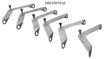

49 Lenny Arm III Components Center Post 4851 Bucket Section 4856 Remote Nose Foot Aluminum Section 485 Nose Section Foot Section 4852 Straight Nose 4847 Auxiliary 5 Wide Bucket 4849 User Guide /2 Foot Aluminum Section 4858 Wide Bucket 4850 Extra Rigid Camera Extension Wide Bucket 4854 Cable System Carrying Case 4766 Front Center Post Cable Bracket 516 Assorted Tools Rear Center Post Cable Bracket Wide Bucket Revision 15-1/2006 Mid Arm Cable Brackets 5146 Rear Cable Bracket 517
 Super Peewee With High Post Kit (For Remote Use Only) Maximum Payload 1,100 lb. (500 kg) 40 (1 m) Minimum Carrying Weight 280 lb. (127 kg) Operating Weight 86 lb.")
 Mobile Crane For Super Nova / Apollo With Platform and 2 riser. Maximum Payload = 2,700 lb. (1,227 kg) Platform at half-circle weighs 285 lb. (11 kg) Platform at full-circle weighs 412 lb.")
50 Lenny Arm III Mounting Options The Lenny Arm III can be mounted on these Chapman/Leonard products: Super Nova 0'8" (9. m) Super Peewee With High Post Kit (For Remote Use Only) Maximum Payload 1,100 lb. (500 kg) 40 (1 m) Minimum Carrying Weight 280 lb. (127 kg) Operating Weight 86 lb. (175 kg) Hybrid With High Post Kit Maximum Payload 1,900 lb. (86 kg) 46.5 (1.19 m) Minimum Carrying Weight 95 lb. (180 kg) Manned = Remove 7.5 in. riser Remote = 7.5 in. riser optional Operating Weight 501 lb. (227 kg) Mobile Crane For Super Nova / Apollo With Platform and 2 riser. Maximum Payload = 2,700 lb. (1,227 kg) Platform at half-circle weighs 285 lb. (11 kg) Platform at full-circle weighs 412 lb. (189 kg) These weights, depending on application, are deducted from the Maximum Payload. Apollo 22'8" (6.9 m) 64 (1.6 m) 49 (1.22 m) 60 (1. m) 6 10 (2 m) CS Base & Super CS Base With 7.5 in. riser Maximum Payload 5,500 lb. (2,500 kg) Minimum Carrying Weight 02 lb. (17 kg) Manned = Remove 7.5 in. riser Remote = 7.5 in. riser optional Operating Weight 771 lb. (50 kg) Hy Hy w/ 7.5 in. riser Maximum Payload 2,900 lb. (1,18 kg) Operating Weight of Unit 25 lb. (148 kg) Min. Carrying Weight 260 lb. (118 kg) Manned = Remove 7.5 in. riser Remote = 7.5 in. riser optional Camera Car Mount Maximum Payload,00 lb. (1,519 kg) (7.5 in. riser optional) Weight of Unit 515 lb. (27 kg) Maverick Maximum Payload 6,000 lb. (2,727 kg) 7 8 (2. m) 46.5 (1.19 m) 72 (1.8 m) 41 (1 m) Super Maverick Maximum Payload 8,000 lb. (,629 kg) Hustler IV With High Post Kit Maximum Payload 1,500 lb. (608.4 kg) Minimum Carrying Weight 465 lb. (211 kg) Manned = Remove 7.5 in. riser Operating Weight 465 lb. (211 kg) ATB Base (7.5 in. riser optional) Maximum Payload 5,500 lb. (2,500 kg) Manned = Remove 7.5 in. riser Remote = 7.5 in. riser optional Operating Weight 2,9 lb. (1,06 kg) Pedolly Chassis w/ Center Post Insert Maximum Payload 1,100 lb. (500 kg) Weight of Unit 248 lb. (112 kg) Min. Carrying Weight 224 lb. (102 kg) Stage 2 Stage 1 1' (.96 m) 9' (2.74 m) 8 6 (2.6 m) 58" (1.47 m) 9 (.98 m) Olympian Maximum Payload 1,700 lb. (795 kg) Weight of Unit 1,790 lb. (81 kg) Raptor Maximum Payload 2,000 lb. (909 kg) Weight of Unit 2,100 lb. (954 kg) Ground Mounting Platform Maximum Payload,000 lb. (1,56 kg) Weight of Unit 206 lb. (9 kg) Olympian III Maximum Payload Stage 1 4,000 lb. (1,818 kg) Stage 2 2,000 lb. (909 kg) Weight of Unit,200 lb. (1,455 kg) The maximum height for the LENNY ARM III is calculated by using the bearings at both ends of the arm as points of reference. Assuming that the arm is at its maximum angle of elevation (56º) and that the arm touches the ground, the maximum height is calculated by multiplying the arm length by sin56º (.829). the forward bearing height is approximately the same as the camera lens height when the camera is underslung. Additional height can be achieved by the use of risers or by overslinging. The maximum payloads and operational weights for the LENNY ARM III have been calculated using a CAMERA PLATE (7 lb.) and NOSE SEGMENT (18 lbs.). Please consider these facts while deciding which configuration is to be chosen for a given task. To calculate specific the specific operational weight for any given configuration, please use the following formula: Specific Operational = Weight BAW (Balanced arm + weight, no payload) payload (Camera, weights, risers, etc.) + payload x balance ratio (Weight in bucket required to balance the given payload) MH Specific operational height on elevated platforms = Platform Mount Height (Ground to mount) Actual Height (H) = MH - (PMH x BR - Actual Mount Height x BR) Forward Length + of Arm x.777 (Center post to + forward bearing) ft. (.45 m) (Center post bearing to mount) 49
51 Quantity Lenny Arm III Triple Cable System Checklist Item Description 0 5' Cable 12 marked Red 10 marked White Extension Cables 8 marked Blue 2 Front Cable, 1 /4" x 46" Blue 2 Front Cable, 1 /4" x 8 /4" White 2 Front Cable, 1 /4" x 1 7 /8" Red 2 64" Rear Cable 2 48" Rear Cable 2 0" Rear Cable 2 5' Rear Cable Extension Cables 2 1' Rear Cable 2 Turnbuckle, 5 /8" x 6" 6 Turnbuckle, 1 /2" x 6" 6 Mid Arm Brackets 2 Center Post Brackets 2 Center Post Spreaders 8 5 /8" x 2 1 /2" Bolt - Center Post 4 Clevis Pin with Clip 2 Rear Cable Bracket 1 Bolt, 5 /8" x 11 1 /2" Grade /8" Nut 44 Quick Release Pins, /8" x 1" (Front Cable) 4 Quick Release Pins, /8"" x 1 1 /2" (Center Post Bracket) 4 Quick Release Pins, 1 /2" x 1 1 /2" (Rear Cable) 1 Open and Close End Wrench, 15 /16" 1 Carrying Case 1 Cart ( Cable System Case) 2 1 /4" x 2 1 /2" Quick Release Spring Assist 1 Lenny Arm III User Guide 50


52 Lenny Arm Bucket Positioning Bolts The Lenny Arm Bucket Positioning Bolts are for aligning and mounting an EMPTY Bucket to the rear of a Lenny Arm. As soon as a Bucket is connected to a Lenny Arm with the Positioning Bolts, the two Retaining Rods MUST be inserted and Knurled Nuts tightened on the Retaining Rods. Bucket Positioning Bolts Retaining Bolts with Knurled Nuts Lenny Arm Bucket The lenny Arm rear section combination should be configured so that the bucket touches the ground before the Lenny Arm vertical travel limits are obtained. Bucket reaches ground. (RECOMMENDED) Bucket does not reach ground. (NOT RECOMMENDED) 51
Lenny Arm II Plus Crane Arm
 Lenny Arm II Plus Crane Arm USER GUIDE Operational Instructions & Specifications Lenny Arm II Plus 2000 Chapman/Leonard Studio Equipment, Inc. It is Chapman/Leonard s goal to provide the best camera support
Super CS Base Remote Arm Base
 Remote Arm Base USER GUIDE Operational Instructions & Specifications Super CS Base (Remote Arm Base) 2001 Chapman/Leonard Studio Equipment, Inc. It is Chapman/Leonard s goal to provide the best camera
LenCin Mini Pedestal USER GUIDE. Operational Instructions & Specifications. LenCin Mini
 LenCin Mini Pedestal USER GUIDE Operational Instructions & Specifications LenCin Mini First Edition - 7/2003 It is Chapman/Leonard s goal to provide the best camera support equipment with exceptional Customer
Pedolly Pedestal USER GUIDE. Operational Instructions & Specifications. Revision 10-10/2013
 Pedolly Pedestal USER GUIDE Operational Instructions & Specifications Pedolly Tool Case NOTE: Keeping the column clean insures smooth precise movements while filming. Wipe down the column with a soft
IV Camera Dolly USER GUIDE Operational Instructions & Specifications
 HybridTM IV Camera Dolly USER GUIDE Operational Instructions & Specifications Hybrid TM IV 203 Chapman/Leonard Studio Equipment, Inc. Customer Service at 888-883-6559 or 88-764-6726. Chapman / Leonard
MINISCOPE 7 TELESCOPING ARM USER GUIDE Operational Instructions & Specifications
 MINISCOPE 7 TELESCOPING ARM USER GUIDE Operational Instructions & Specifications MINISCOPE 7 TELESCOPING ARM USER GUIDE Operational Instructions & Specifications www.chapman-leonard.com @chapman_leonard
Equipment Catalog (818)
") Equipment Catalog (818) 316-1080 www.panavision.com For over fifteen years, Panavision Remote Systems has been the leader in providing camera systems, telescopic cranes, remote heads and camera support
Equipment Catalog (818) 316-1080 www.panavision.com For over fifteen years, Panavision Remote Systems has been the leader in providing camera systems, telescopic cranes, remote heads and camera support
<THESE INSTRUCTIONS MUST BE GIVEN TO THE END USER> B&W Trailer Hitches 1216 Hawaii Road / PO Box 186 Humboldt, KS P: F:
 B&W Trailer Hitches 26 Hawaii Road / PO Box 86 Humboldt, KS 66748 P:620.473.3664 F:620.869.903 Ford OEM Mount System Installation Instructions 20,000
<THESE INSTRUCTIONS MUST BE GIVEN TO THE END USER> B&W Trailer Hitches 1216 Hawaii Road / PO Box 186 Humboldt, KS P: F:
 B&W Trailer Hitches 26 Hawaii Road / PO Box 86 Humboldt, KS 6678 P:620.73.366 F:620.869.903 Ford OEM Mount System Installation Instructions 20,000 LBS.
<THESE INSTRUCTIONS MUST BE GIVEN TO THE END USER> B&W
 B&W Trailer Hitches 26 Hawaii Road / PO Box 86 Humboldt, KS 6678 P:620.73.366 F:620.869.903 GM Puck Mount System Installation Instructions 20,000 LBS.
B&W Trailer Hitches 1216 Hawaii Road / PO Box 186 Humboldt, KS P: F:
 B&W Trailer Hitches 1216 Hawaii Road / PO Box 186 Humboldt, KS 66748 P:620.473.3664 F:620.473.3766 NOTE: We recommend reading instructions before beginning the installation. GM OEM Mount System Slider
The H-MAC Heavy Metal Articulating Chassis Construction Guide
 The H-MAC Heavy Metal Articulating Chassis Construction Guide The Heavy Metal Chassis is constructed with two identical drive modules built using 10 mechanical sub-assemblies. The drive modules are integrated
<THESE INSTRUCTIONS MUST BE GIVEN TO THE END USER> B&W Trailer Hitches 1216 Hawaii Road / PO Box 186 Humboldt, KS P: F:
 B&W Trailer Hitches 26 Hawaii Road / PO Box 86 Humboldt, KS 6678 P:620.73.366 F:620.869.903 RAM OEM Mount System Installation Instructions 25,000 LBS.
HD 7700 Setup & Operator Manual
 HD 7700 Setup & Operator Manual Issue 1 December, 01 Performance Design Inc. The Heavy Duty Ultima (HD 7700) electric punch has been designed to punch most any job that may pass through your bindery or
Model 3770 WARNING. Failure to comply with the safety information in these instructions could result in serious injury or death.
 B&W Trailer Hitches 1216 Hawaii Road / PO Box 186 Humboldt, KS 66748 P:620.473.3664 See Limited Lifetime Warranty at F:620.869.9031 bwtrailerhitches.com/warranty NOTE: We recommend reading instructions
B&W Trailer Hitches 1216 Hawaii Road / PO Box 186 Humboldt, KS P: F:
 B&W Trailer Hitches 1216 Hawaii Road / PO Box 186 Humboldt, KS 66748 P:620.473.3664 F:620.869.9031 NOTE: We recommend reading instructions before beginning the installation. Ford OEM Mount System Slider
To learn more about this model, call or visit giuffre.com today! GIUFFRE.COM
 TC300 SERIES TELESCOPIC CRANE 2 CONTENTS //////////////////////////////////////////////////////////////////////////////////////// Crane Features...4 Chassis Data... 5 Outrigger Extension... 6 Sub Frame...6
Range Diagram and Lifting Capacity RT230. Cranes 30 TON LIFTING CAPACITY RANGE DIAGRAM 30' - 94' BOOM REDUCTION IN MAIN BOOM CAPACITY
 Range Diagram and Lifting Capacity Cranes 30 TON LIFTING CAPACITY RANGE DIAGRAM 30' - 94' BOOM Dimensions are for largest factory furnished hook block and hook & ball, with anti-two block activated COUNTER
INSTALLATION INSTRUCTIONS
 INSTALLATION INSTRUCTIONS WARNING: NEVER EXCEED YOUR VEHICLE MANUFACTURER'S RECOMMENDED TOWING CAPACITY A20 5TH WHEEL HITCH TABLE OF CONTENTS Page# Description 1 Warnings & Precautions 2 - Assembly & Installation
Cranes. Range Diagram and Lifting Capacity RT TON LIFTING CAPACITY RANGE DIAGRAM 33' - 110' BOOM
 Range Diagram and Lifting Capacity Cranes 55 TON LIFTING CAPACITY RANGE DIAGRAM 33' - 110' BOOM Dimensions are for largest factory furnished hook block and hook & ball, with anti-two block activated COUNTER
POMPE AUTOADESCANTI SELF-PRIMING ELECTRO PUMP ACM DISASSEMBLY AND ASSEMBLY INSTRUCTIONS FOR MULTISTAGE SELF-PRIMING PUMPS
 POMPE AUTOADESCANTI SELF-PRIMING ELECTRO PUMP ACM DISASSEMBLY AND ASSEMBLY INSTRUCTIONS FOR MULTISTAGE SELF-PRIMING PUMPS Ed. 02/2011 5 WARNING These instructions are for the maintenance personnel for
Important Operation Tips:
 What s Included Main Jib Assembly Unit Jib Level Knob Standard Quick Release Camera Plate 75mm Bowl mounted on Release Plate Counterweight Sandbag Carabineer and washer for Weight bag 5.5 Lb Counterweight
Cranes. Range Diagram and Lifting Capacity RT TON LIFTING CAPACITY RANGE DIAGRAM 40' - 126'
 Range Diagram and Lifting Capacity Cranes 80 TON LIFTING CAPACITY RANGE DIAGRAM 40' - 126' BOOM Dimensions are for largest factory furnished hook block and hook & ball, with anti-two block activated COUNTER
3. Operating instructions: Minor 200
 1. Technical specifications 3. Operating instructions: Minor 200 Copyright 2015 by Endecotts Ltd. 13 1. Setting up Technical specifications SIEVE SHAKER MODEL: Minor 200 General Information The Minor 200
Load Chart Exercise Workbook
 Load Chart Exercise Workbook (508) 212-4735 Copy Right 2017 For Exam Use Only BRODERSON IC-80-2D RATED LIFTING CAPACITIES IN POUNDS LOAD RADIUS IN FEET 5 6 8 10 12 14 16 18 20 22 24 26 28 30 32 34 ON RUBBER
Multistrada (MTS) Tank Installation Notes. Tools Required. Phase 1: Remove Fairings. Phase 2: Remove Fuel Tank
 Tank Installation Notes. Tools Required. Phase 1: Remove Fairings. Phase 2: Remove Fuel Tank") The California Cycleworks MTS tank provides an aftermarket alternative to the OEM nylon fuel tanks as used on aircooled Desmodue Ducati Multistrada 1100, 1000, and 620 models. This fuel tank is NOT for
The California Cycleworks MTS tank provides an aftermarket alternative to the OEM nylon fuel tanks as used on aircooled Desmodue Ducati Multistrada 1100, 1000, and 620 models. This fuel tank is NOT for
BOGERT HMMWV LIFTING JACK KIT PART NR: 30M-HVBMI NSN:
 BOGERT HMMWV LIFTING JACK KIT PART NR: 30M-HVBMI NSN: 5120-01-573-3382 Tire Replacement Jack Operating Instructions Model: 30M-HV Jack with BMI P40A Hydraulic Pump Bogert International Inc. 3606 N. Swallow
Installation Instructions
 PIN BOX SHOWN ASSEMBLED Equipment Required: Fastener Kit: ST100F Wrenches: 15/16, 1 1/8 Drill Bits: Not Required White Lithium Grease, Torque Wrench Installation Instructions DEALER/INSTALLER: (1) Provide
IMPORTANT! DO NOT THROW AWAY THE SHIPPING CARTON AND PACKING MATERIAL
 Operator s Manual IMPORTANT! DO NOT THROW AWAY THE SHIPPING CARTON AND PACKING MATERIAL ii Table of Contents Operator Safety... 1 Introduction... 2 Unpacking and Setup... 3 Unpacking... 3 Setup... 4 ROCKET
Prusa i3 Printer Assembly Guide
 Prusa i3 Printer Assembly Guide Special thanks to Carlos Sanchez and Miguel Sanchez for the graphics. All graphics captured from their great animation: http://www.carlos-sanchez.com/ Prusa3/ For copyright
Quattro-SL. Operators Guide. Pedestal. Vinten Camera Control Solutions
 Operators Guide Quattro-SL Pedestal Vinten Camera Control Solutions Quattro-SL PEDESTAL Publication Part No. V3963-4981 Issue 1 Copyright Vinten Broadcast Limited 2006 All rights reserved throughout the
DC Series Installation Manual (# )
") DC Series Installation Manual (# 101630) Page 1 of 33 In this booklet you will find: TOWER INSTALLATION... 3 U-Bolt Style mount... 4 Side Frame Style mount... 4 PIVOT INSTALLATION... 5 External Pivot Installation:
DC Series Installation Manual (# 101630) Page 1 of 33 In this booklet you will find: TOWER INSTALLATION... 3 U-Bolt Style mount... 4 Side Frame Style mount... 4 PIVOT INSTALLATION... 5 External Pivot Installation:
OWNER'S MANUAL FOR 135LB STAINLESS STEEL SPREADER SNOWRATOR
 2017 OWNER'S MANUAL FOR 135LB STAINLESS STEEL SPREADER SNOWRATOR AES L. T. RICH PRODUCTS 11/16/2017 TABLE OF CONTENTS 1.0 SHIPPING CONTENTS... 2 2.0 IMPORTANT INFORMATION... 3 2.1 ABOUT THIS MANUAL...
SCAN OPTICS SO-5800 MICROSCOPE ASSEMBLY MANUAL
 SCAN OPTICS SO-5800 MICROSCOPE ASSEMBLY MANUAL SO-5800 Ophthalmic Microscope Assembly Manual Page 2 of 25 CONTENTS INTRODUCTION... 3 PACKING LIST... 5 MECHANICAL ASSEMBLY... 6 Floor stand base and pillar...
IL500 Sierra Inclined Platform Lift
 IL500 Sierra Inclined Platform Lift Installation & Service Manual www.harmar.com 800-833-0478 IMPORTANT: Read and understand this manual thoroughly before attempting to install or operate the lift. If
panelclaw.com Polar Bear III for 10 Degree
 panelclaw.com Polar Bear III for 10 Degree Installation Manual Document Number 9910024 Rev A March 2014 Revision History Rev ECO # Date Description of Changes Approved By 01 TBD 02-FEB-14 Initial Draft
1203AA GM A-BODY Double Adjustable Trailing Arms
 1203AA 64-67 GM A-BODY Double Adjustable Trailing Arms Warning: This installation should be performed by a trained professional. Note, pictures in this booklet are from a 77-96 GM B Body. Installation
The EFL 2000/1 & 2 User Guide Test Sieve Shaker. Contents
 The EFL 2000/1 & 2 User Guide Test Sieve Shaker ISSUE 04-02 Contents Description Page 1 Setting Up: 2-8 Unpacking 2 Assembly 3 Clamping Assembly 4 Electrical Connections 5 Sieve Stacking 6 8 Operating
INSTALLATION INSTRUCTIONS
 INSTALLATION INSTRUCTIONS WARNING: NEVER EXCEED YOUR VEHICLE MANUFACTURER'S RECOMMENDED TOWING CAPACITY Q24 5TH WHEEL HITCH TABLE OF CONTENTS Page# Description 1 Warnings & Precautions 2 Assembly & Installation
RST INSTRUMENTS LTD.
 RST INSTRUMENTS LTD. MEMS Portable Tiltmeter System (Biaxial) Instruction Manual Model ICTS0004, IC6800S Readout Copyright 2012 Ltd. All Rights Reserved. Ltd. 11545 Kingston St., Maple Ridge, B.C. Canada
KITE-33 STARTER PACKAGE SET UP AND OPERATION MANUAL
 KITE-33 STARTER PACKAGE SET UP AND OPERATION MANUAL SHOWN WITH OPTIONAL ACCESSORIES All rights reserved. No part of this document may be reproduced, stored in a retrieval system, or transmitted by any
40' ' POWERED BOOM: MODE 1 40' - 126' POWERED BOOM: MODE 2
 Range Diagram and Lifting Capacity Cranes 100 TON LIFTING CAPACITY 40' - 97.3' POWERED BOOM: MODE 1 40' - 126' POWERED BOOM: MODE 2 CRANE WORKING CONDITIONS DIMENSIONS ARE FOR LARGEST FACTORY FUR- NISHED
Air Brake Adjustment. What You ll Learn After reading this chapter you will be able to:
 8 Air Brake Adjustment Fast Fact Your company may have a maintenance crew to keep vehicles safely running. But one person alone is ultimately responsible to ensure that the brakes are operating properly
Range Diagram and Lifting Capacity T Cranes RANGE DIAGRAM BOOM
 Range Diagram and Lifting Capacity T340-1 Cranes RANGE DIAGRAM 30-94 BOOM Dimensions are for largest factory furnished hook block and hook & ball, with anti-two block activated COUNTER WEIGHT BOOM LENGTH
Installation Guide Current Ford F-250 & Ford F-350 Super Duty. Product Code: 109 & 119
 Installation Guide 2008 - Current Ford F-250 & Ford F-350 Super Duty Product Code: 109 & 119 September 1, 2012 Tools Needed Components Included 3/8" Drill P2 Tip #2 Philips Screwdriver 1/2" Drill Bit Hinged
Pre-Assembly. 1 Reinstall the four kips that engage with the Tilt and Pan Locks. These kips have been removed for travel in the Case.
 QUICKST RT Axis Jib Axis Contents A G B C H J K D E F A Rear Section B 1 diameter Weight Support Bar C 2 lb Trim Weight D Pedestal E Arm Section F Front Forks G 100mm Bowl H Weight Clips J Tie Down K 5/32
Vision Ped Plus. Operators Guide. Studio Pedestal. Vinten Camera Control Solutions
 Operators Guide Vision Ped Plus Studio Pedestal Vinten Camera Control Solutions Vision Ped Plus Studio Pedestal Publication Part No. 3951-8 Issue 1 Copyright Vinten Broadcast Limited 2002 All rights reserved
Installation Instructions
 Description Instructions given in this bulletin apply to either a standard, unshielded or high-performance, shielded antenna. The antenna consists of a two-piece reflector, braced by a back structure;
Operation Guide. Hydraulic Leveling Systems #2000, #2010, #3000, and # Table of Content. Introduction
 Operation Guide Operation Guide Hydraulic Leveling Systems #2000, #2010, #3000, and #30130 Table of Content Page Introduction 1 Safety Information 1 Operation 2 Control Panel 3 Manual Mode 3 Auto Mode
Operation Guide. Operation Guide. Winnebago Hydraulic Leveling Systems by Kwikee. Introduction. Table of Content WARNINGS
 Operation Guide 05/07 Kwikee #1422192 Rev. 0F Table of Content Page Introduction 1 Safety Information 1 Operation 2 Control Panel 3 Manual Leveling 3 Automatic Leveling 3 Remote Operation 4 Stabilizing
: 1250 gpm in the deck mode : 800 gpm while operating in the ground base - Dual Inlet : 1000 gpm while operating in the ground base - Single Inlet
 APOLLO HI-RISER MONITOR STYLE 3433/3431 INSTALLATION, OPERATING, AND MAINTENANCE INSTRUCTIONS The following is intended to provide the basic instructions for installation, operation and maintenance of
LIFT Drop Spindle Lift Kit E-Z-Go RXV Gas or Electric Installation Instructions
 LIFT-107 6 Drop Spindle Lift Kit E-Z-Go RXV Gas or Electric Installation Instructions Contents of LIFT-107 E-Z-Go RXV Drop Spindle Lift Kit: a (1 ea.) Driver Side Spindle b (1 ea.) Passenger Side Spindle
Series 1400 Hydraulic Crane 33 Ton Load Ratings
 Series 1 Hydraulic Crane 33 Ton Load Ratings! DANGER AN UNTRAINED OPERATOR SUBJECTS HIMSELF AND OTHERS TO DEATH OR SERIOUS INJURY YOU MUST NOT OPERATE THIS CRANE UNLESS You have been trained in the safe
Series 1400A Hydraulic Crane 33 Ton
 Series 1A Hydraulic Crane 33 Ton Load Ratings DANGER AN UNTRAINED OPERATOR SUBJECTS HIMSELF AND OTHERS TO DEATH OR SERIOUS INJURY YOU MUST NOT OPERATE THIS CRANE UNLESS You have been trained in the safe
EL Beam Sensors Standard & SC Versions
 EL Beam Sensors Standard & SC Versions 56801399 Copyright 2008 Slope Indicator Company. All Rights Reserved. This equipment should be installed, maintained, and operated by technically qualified personnel.
Chapter 1 Safety and Operation
 Chapter 1 Safety and Operation General The importance of safe operation cannot be over emphasized. Carelessness and neglect on the part of operators, job supervisors and planners, rigging personnel, and
MULTI-POLE MOUNT - G2 ASSEMBLY INSTRUCTIONS. step-by-step assembly and installation. Version 1, Rev D SP PCN
 MULTI-POLE MOUNT - G2 ASSEMBLY INSTRUCTIONS step-by-step assembly and installation Version 1, Rev D SP3287-2 PCN 042412-1 The Multi-Pole Mount - G2 A few words about the product The Multi-Pole Mount -
Model 3400 ATTENTION: WARNING
 B&W Trailer Hitches 1216 Hawaii Road / PO Box 186 Humboldt, KS 66748 P:620.473.3664 F:620.473.3766 NOTE: We recommend reading instructions before beginning the installation. Companion Slider Hitch Installation
4- Piston Caliper Big Brake Kit Installation Instructions
 4- Piston Caliper Big Brake Kit Installation Instructions For: Austin - Healey BJ8 from (c)26705-on PART # 586-725 440 Rutherford St. Goleta, CA 93117 1-800-667-7872 FAX 805-692-2525 www.mossmotors.com
SUPER CAPACITOR CHARGE CONTROLLER KIT
 TEACHING RESOURCES ABOUT THE CIRCUIT COMPONENT FACTSHEETS HOW TO SOLDER GUIDE POWER YOUR PROJECT WITH THIS SUPER CAPACITOR CHARGE CONTROLLER KIT Version 2.0 Teaching Resources Index of Sheets TEACHING
Range Diagram and Lifting Capacity T Cranes. View thousands of Crane Specifications on FreeCraneSpecs.com RANGE DIAGRAM BOOM
 Range Diagram and Lifting Capacity Cranes RANGE DIAGRAM 30-94 BOOM Dimensions are for largest factory furnished hook block and hook & ball, with anti-two block activated COUNTER WEIGHT BOOM LENGTH UPPERSTRUCTURE
INSTALLATION & OWNER S MANUAL
 Rev. R p. 1 of 16 INSTALLATION & OWNER S MANUAL V4211 HARD SIDED CAB KIT and/or V4275 CAMO HARD SIDED CAB KIT INSTALLATION & OWNER S MANUAL The contents of this envelope are the property of the owner.
Safety - Installation and Operation:
 4x4 or 4x2 Instructions EZGO Electric Cars Thank you for purchasing your 4x4 or 4x2 conversion kit. Safety at all times whether during installation or operation is utmost importance. Before After!!!!!!!!!!!!!!
series 2802 product guide features BOOM TRUCKS
 series 2802 BOOM TRUCKS features 28 Ton (24,4 mton) Capacity 4-Section 102' (31,0 m) Proportional Boom 4-Section 92' (28.0 m) Proportional Boom 2-Section 26' (7,9 m) to 46' (14,0 m) Telescopic Jib 157'
INSTALLATION / OPERATING INSTRUCTIONS Reese Elite Series FIFTH WHEEL SLIDER HITCH
 INSTALLATION / OPERATING INSTRUCTIONS Reese Elite Series FIFTH WHEEL SLIDER HITCH DEALER/INSTALLER: (1) Provide this Manual to end user. (2) Physically demonstrate hitching and unhitching procedures in
Cranes. Range Diagram and Lifting Capacity RT345-1XL 45 TON LIFTING CAPACITY RANGE DIAGRAM 33.75' - 105' BOOM
 Range Diagram and Lifting Capacity RT345-1XL Cranes 45 TON LIFTING CAPACITY RANGE DIAGRAM 33.75' - 105' BOOM DIMENSIONS ARE FOR LARGEST FACTORY FURNISHED HOOK BLOCK AND HOOK & BALL, WITH ANTI-TWO BLOCK
3-TONNE GARAGE JACK OPERATION & MAINTENANCE INSTRUCTIONS MODEL NO: CTJ3000GB PART NO: ORIGINAL INSTRUCTIONS
 3-TONNE GARAGE JACK MODEL NO: CTJ3000GB PART NO: 7623032 OPERATION & MAINTENANCE INSTRUCTIONS ORIGINAL INSTRUCTIONS GC1216 2 INTRODUCTION Thank you for purchasing this CLARKE Garage Jack. Before attempting
GARAGE JACK MODEL NO: CTJ3000G PART NO: OPERATION & MAINTENANCE INSTRUCTIONS ORIGINAL INSTRUCTIONS
 GARAGE JACK MODEL NO: CTJ3000G PART NO: 7623030 OPERATION & MAINTENANCE INSTRUCTIONS ORIGINAL INSTRUCTIONS GC1217 INTRODUCTION Thank you for purchasing this CLARKE Garage Jack. Before attempting to use
RT555 TEREX. rough terrain crane 55 ton capacity. range diagram & lifting capacities. Range Diagram ( boom) HOOK BLOCK WEIGHTS
 HOOK BLOCK WEIGHTS") TEREX RT5 rough terrain crane ton capacity range diagram & lifting capacities DIMENSIONS ARE FOR LARGEST FACTORY FURNISHED HOOK BLOCK AND HOOK & BALL, WITH ANTI-TWO BLOCK ACTIVATED Range Diagram (33-1
TEREX RT5 rough terrain crane ton capacity range diagram & lifting capacities DIMENSIONS ARE FOR LARGEST FACTORY FURNISHED HOOK BLOCK AND HOOK & BALL, WITH ANTI-TWO BLOCK ACTIVATED Range Diagram (33-1
Build your own THUNDERBIRD 2
 PACK 01 STAGE PAGE 01 Nose assembly and Elevator Car rear wheels 3 02 Cockpit interior and Elevator Car 1 completion 7 03 Missile launcher and Thunderbird 4 11 04 Nose assembly and the Tracy brothers 15
DynaCon Instruction Manual
 DynaCon Instruction Manual Table of Contents Technical Specification & Warranty.... 3 Construction, Benefits & Safe Operating Procedures... 4 Noise Levels... 5 Installation, Operation & Maintenance...
Osprey Elite. Operators Guide. Pedestal. Vinten Camera Control Solutions
 Operators Guide Osprey Elite Pedestal Vinten Camera Control Solutions Osprey Elite Pedestal Publication Part No. 3574-8 Issue 4 Copyright Vinten Broadcast Limited 2005 All rights reserved throughout the
ASSEMBLY, INSTALLATION, AND REMOVAL OF CONTACTS AND MODULES
 ASSEMBLY, INSTALLATION, AND REMOVAL OF CONTACTS AND MODULES FOR THERMOCOUPLE CONTACTS AND MODULES Table of Contents SECTION 1 RECEIVER CONTACT ASSEMBLY INSTRUCTIONS SECTION 2 ITA CONTACT ASSEMBLY INSTRUCTIONS
Quartz One. Operators Guide. Pedestal. Vinten Camera Control Solutions
 Operators Guide Quartz One Pedestal Vinten Camera Control Solutions Quartz One Pedestal Publication Part No. 3825-8 Issue 1 Copyright Vinten Broadcast Limited 2002 All rights reserved throughout the world.
Last date for sending comments : 30 November 2011
 For comments only Draft Indian Standard AUTOMOTIVE VEHICLES METHODS OF MEASUREMENT OF BRAKING COEFFICIENT OF ROAD SURFACES Part 2 Pendulum Method Not to be reproduced or used as a standard without the
Adjusting brake shoes for AutoPark parking brake
 Adjusting brake shoes for AutoPark parking brake This document is a compilation of several separate writeups. What we're trying to do here is consolidate the necessary information needed for you to make
632 Western Avenue Henniker, New Hampshire Tel. (603) Fax (603) POSITION OF THE ROLLER PLATES
 Fax (603) POSITION OF THE ROLLER PLATES") POSITION OF THE ROLLER PLATES The roller plate must be positioned as shown. The measurement to both of the roller plates is taken from the face of the kingpin shaft to the inside edge of the roller wheel
POSITION OF THE ROLLER PLATES The roller plate must be positioned as shown. The measurement to both of the roller plates is taken from the face of the kingpin shaft to the inside edge of the roller wheel
1. AEROSTAT INTRODUCTION
 1. AEROSTAT INTRODUCTION The tethered aerostat, also known as a blimp or kite balloon, has been in use since the early 19 th Century for a variety of observation purposes. The use of aerostats for signal
Fuel supply system, servicing (vehicles with front wheel drive and 1.8 ltr. turbo or 2.8 ltr. engine)
") Page 1 of 49 20-6 Fuel supply system, servicing (vehicles with front wheel drive and 1.8 ltr. turbo or 2.8 ltr. engine) Note: VAG1921 spring clamp pliers are recommended for installation Always replace
Page 1 of 49 20-6 Fuel supply system, servicing (vehicles with front wheel drive and 1.8 ltr. turbo or 2.8 ltr. engine) Note: VAG1921 spring clamp pliers are recommended for installation Always replace
The Powermatic User Guide Test Sieve Shaker
 The Powermatic User Guide Test Sieve Shaker ISSUE 04-02 Contents Description Page 1 Setting Up: 2-8 Unpacking 2 Assembly 3-4 Levelling 4 Electrical Connections 5 Sieve Stacking 6-8 Operating Instructions
T 775. truck crane 75 ton capacity. range diagram & lifting capacities. Range Diagram (40' - 126' boom)
") T 7 truck crane ton capacity range diagram & lifting capacities DEFLECTIONS NOT SHOWN 6' - 9" 4' - 8" DIMENSIONS ARE FOR LARGEST FACTORY FURNISHED HOOK BLOCK AND HOOK & BALL, WITH ANTI-TWO BLOCK ACTIVATED
T 7 truck crane ton capacity range diagram & lifting capacities DEFLECTIONS NOT SHOWN 6' - 9" 4' - 8" DIMENSIONS ARE FOR LARGEST FACTORY FURNISHED HOOK BLOCK AND HOOK & BALL, WITH ANTI-TWO BLOCK ACTIVATED
Installation instructions for Camaro/Firebird and Nova* Windshield Wiper Systems
 Installation instructions for 1967-69 Camaro/Firebird and 1968-74 Nova* Windshield Wiper Systems The Raingear 1967-69 Camaro/Firebird and 1964-74 Nova wiper system is designed for ease of installation
Q5 5 th Wheel. Unpacking Assembly / Installation
 PA1 Unpacking Assembly / Installation Installer: Read and understand this manual. Fully instruct and demonstrate the operation of this 5 th Wheel Hitch to the End-User. Include the importance of observing
16K Reese Revolution. Operating Instructions
 Operating Instructions DEALER: (1) Provide this Manual to end user END USER: (1) Read and follow this Manual every time you use Sidewinder. (2) Save this Manual for Future Reference. PIN BOX SHOWN ASSEMBLED
LIFT-506 BMF Lift Kit Club Car DS Gas & Electric Installation Instructions
 LIFT-506 BMF Lift Kit Club Car DS Gas & Electric 2003.5-09 Installation Instructions Contents of LIFT-506 Club Car DS BMF Lift Kit: a (1 ea.) BMF Front Suspension b (1 ea.) Driver Side Upper A-Arm c (1
Electric Winch Installation & Operation Manual Permanent Magnet 12 V DC EMD2000SS STAINLESS STEEL WINCH
 Endurance Marine Products Ltd 210 19138 26 Ave Surrey, BC V3S 3V7 T 604 535 0669 TOLL FREE 1 877 535 0669 Info@endurance-marine.com www.endurance-marine.com Electric Winch Installation & Operation Manual
LIFT Standard A-Arm Lift Kit Club Car Precedent Installation Instructions
 LIFT-563 6 Standard A-Arm Lift Kit Club Car Precedent Installation Instructions Contents of LIFT-563 Club Car Precedent Lift Kit: a (1 ea.) Front Suspension b (1 ea.) Driver Side Upper A-Arm c (1 ea.)
LIFT-507 BMF Lift Kit E-Z-Go RXV Gas or Electric Installation Instructions
 LIFT-507 BMF Lift Kit E-Z-Go RXV Gas or Electric Installation Instructions Contents of LIFT-507 E-Z-Go RXV BMF Lift Kit: a (1 ea.) BMF A-Arm Assembly b (1 ea.) Driver Side Shock Tower c (1 ea.) Passenger
Range Diagram and Lifting Capacity RT665. Cranes 65 TON LIFTING CAPACITY RANGE DIAGRAM 36' - 111' BOOM REDUCTION IN MAIN BOOM CAPACITY
 Range Diagram and Lifting Capacity Cranes 65 TON LIFTING CAPACITY RANGE DIAGRAM 36' - 111' BOOM DIMENSIONS ARE FOR LARGEST FACTORY FURNISHED HOOK BLOCK AND HOOK & BALL, WITH ANTI-TWO BLOCK ACTIVATED COUNTER
Altec LMAP. (Load Moment and Area Protection) Telescopic Boom Cranes. Calibration
 Telescopic Boom Cranes. Calibration") Altec LMAP (Load Moment and Area Protection) Telescopic Boom Cranes Calibration Contents System Components...1 Anti-Two Block...1 Area Alarm...1 Boom Angle Sensor...1 Display...1 Extension Sensor...2 Function
Altec LMAP (Load Moment and Area Protection) Telescopic Boom Cranes Calibration Contents System Components...1 Anti-Two Block...1 Area Alarm...1 Boom Angle Sensor...1 Display...1 Extension Sensor...2 Function
Meinzer II TM. Testing Sieve Shaker
 Meinzer II TM Testing Sieve Shaker Operation & Set-up Manual Model: 18480100 CSC Scientific, Inc. 2799-C Merrilee Drive Fairfax, VA 22031 USA Telephone: (703) 876-4030 (800) 621-4778 Fax: 703-280-5142
System 1 Modular Post-Mount Supports
 System 1 Modular Post-Mount Supports TMC Ametek, Peabody, Massachusetts Page 1 System 1 Modular Post-Mount Support Introduction System 1 is a family of modular post mounted Vibration Isolators and Rigid
B&W Trailer Hitches 1216 Hawaii Road / PO Box 186 Humboldt, KS P: F: " Split Lock Washers 8
 B&W Trailer Hitches 1216 Hawaii Road / PO Box 186 Humboldt, KS 66748 P:620.473.3664 F:620.869.9031 NOTE: We recommend reading instructions before beginning the installation. Companion Slider Hitch Installation
<THESE INSTRUCTIONS MUST BE GIVEN TO THE END USER> B&W
 B&W Trailer Hitches 6 Hawaii Rd / PO Box 86 Humboldt, KS 66748 P:60.473664 F:60.869.903 Turnoverball Gooseneck Hitch Installation Instructions MODEL 08
IDEAL Stripmaster Model 950 Wire Stripper #45-950
 IDEAL Stripmaster Model 950 Wire Stripper #45-950 IDEAL Stripmaster Model 950 Wire Stripper Introduction The IDEAL Stripmaster Model 950 Wire Stripper is an electrically operated, pneumatic precision production
Shaver Industries. Assembly Instructions Spring-Assist Vertical Vinyl Curtain Door
 Shaver Industries 20 Steckle Place, Kitchener, ON N2E 2C3 Ph 1(888) 766 8328 www.shaverinc.com Assembly Instructions Spring-Assist Vertical Vinyl Curtain Door System Overview: Your Shaver's Spring-Assist
OPERATION AND MAINTENANCE INSTRUCTIONS
 OPERATION AND MAINTENANCE INSTRUCTIONS 334 SERIES THREE-PIECE BALL VALVES 1/4 to 2-1/2 Installation and Operation Always install your valve according to accepted industry standards and practices and operate
Agricultural Track Service Procedures Removal, Installation, Inspection and Alignment
 Agricultural Track Service Procedures Removal, Installation, Inspection and Alignment CNH STX Quadtrac Series CPB-0303 8/1/2006 Table of Contents Introduction...1 Track Terminology...1 General Tooling
Type N550 Snappy Joe Emergency Shutoff Valves
 Instruction Manual MCK-1149 Type N550 March 2010 Type N550 Snappy Joe Emergency Shutoff Valves Failure to follow these instructions or to properly install and maintain this equipment could result in an
3.25 Ton Heavy Duty Floor Jack
 Please dispose of packaging for the product in a responsible manner. It is suitable for recycling. Help to protect the environment, take the packaging to the local amenity tip and place into the appropriate