ACCESS TO MARS: (Part 1) EARTH TO MARS TRANSIT - LOGISTICS ALTERNATIVES John K. Strickland, Jr.
|
|
|
- Posy Holland
- 6 years ago
- Views:
Transcription
1 ACCESS TO MARS: (Part 1) EARTH TO MARS TRANSIT - LOGISTICS ALTERNATIVES John K. Strickland, Jr. (jkstrick@io.com) Presented at the International Space Development Conference Huntsville, Alabama, May 18-22, 2011 Initial version presented at the 13th International Mars Society Convention, Dayton, Ohio, August 5-8, 2010
2
3 Space Transport and Logistics Issues Covered Types and Purposes of Mars Expeditions Major Decisions and Alternatives for Earth to Mars Transit Systems. Getting Mars Equipment into Low Earth Orbit Connecting HLV design to Mars Missions. Types of Mars Transit vehicles Near-Earth Space Infrastructure Needed. Getting to and into Low Mars Orbit and back Low Mars Orbit Base & Needed Infrastructure. Down-select of choices for a re-usable system
4 Types of Mars Expeditions Flyby of Mars only. Mars Orbit and Phobos with Tele-operation of surface robotics and base equipment. Flags and Footprints (a few trips only) using expendable booster and in-space vehicles. Antarctic Style Scientific Bases (semi-permanent & open-ended) with reusable vehicles & ISRU. Permanent Scientific Bases - major ISRU. Base with commerce to support government. Bases and Settlement(s) with commerce.
5 Rational for avoiding Flags and Footprints Missions F&F is a dead end road. If you build a "flags and footprints" (non-re-usable) architecture, then all you will get is a short series of flags and footprints missions. Period. This path is not sustainable due to the continuing high cost of building replacement vehicles. There could be a very long gap afterward before Human Mars exploration is resumed, just like the one after Apollo. This creates a risk of loss of public interest and support similar to the post-apollo period. It creates no Mars infrastructure usable for future missions. It is inefficient and produces relatively few scientific results for the money spent. (The most important Mars Direct Concepts such as equipment pre-positioning and using local materials - are very useful for many kinds of missions).
6 How to avoid Flags and Footprints Create a fleet of re-usable, preferably air-breathing HLV Boosters, operated by private companies, to greatly reduce cost of launching payloads to LEO. Make it a policy to design all in-space vehicles to be reusable except in very specific situations. Create an in-space infrastructure of propellant depots and crew refuges using fallback base & redundant equipment concepts, similar to those used on Everest expeditions. Create a powerful, compact electric power source to operate VASIMR engines for Mars Transit. (Alternate method). Conduct all manned Mars operations as an international enterprise to share costs, with each country contributing one or more major components. Plan missions to be on-going without major interruptions.
7 Interdependency of Manned Mars Entry Vehicle Types with Booster Diameter You cannot assemble a re-usable entry vehicle with an integral aeroshell in Earth orbit (no factory equipment and no manpower), so such vehicles must be launched intact from the surface. Two types of Mars Entry Vehicle concepts exist: 1. Wide base Blunt body (capsule shaped) 2. Narrow Body lifting body or cylindrically shaped Wide body (up to 15 meters wide at the base) landers are more stable and can carry more cargo since they need less fuel due to entry drag, but they need an HLV with a 10 meter or wider diameter. Narrow body landers carry less cargo but they can be launched on some currently projected HLV boosters with an 7-8 meter diameter. The booster s launch cost must be affordable for dozens of launches per year to support a continuing Mars exploration program. We can choose a vehicle design based on the booster available OR we can pick a booster design to FIT the needs of the payload (the lander).
8 Capsule-shaped blunt-body landers - a good approximation of a Wide Body Mars Ferry. NOTE: widths in meters, not feet! Capsule shape allows bulky cargo to be landed. (Credit: Georgia Tech J. Christian 06)
9 Narrow Body Mars Entry Vehicle Using a Rigid Cylindrical Aero-shell which is expended like a launch shroud before landing as shown at right size: 10 x 30 meters Note Entry attitude for Lift and control at center Credit: NASA: Entry, Descent and Landing Systems Analysis Study: Phase 1 Report Thomas A. Zang et al
10 Types of Re-usable first Stages for HLVs ordered by increasing development cost Cluster of Boosters which separate and are recovered individually from the water. Cluster of Boosters where each one separates and individually flies back to a landing strip. Single Large Rocket-powered airframe which flies back to a landing strip with jet engines. Single very Large Rocket-powered cone-shaped airframe which lands vertically on its own rockets. Single fly-back rocket powered vehicle which captures its own LOX supply during flight & for the second stage engine. Fully air-breathing (Hypersonic) Booster which flies itself back to a landing strip with scramjets. Highest development cost = lowest operating cost. Operating costs usually far exceed development costs.

11 Examples of evolutionary booster CLUSTERS based on Atlas. These are not designed to be recovered or re-used. Note some payload shrouds have a larger diameter than the booster. (Source - United Launch Alliance)
12 Why Solid Booster Based Rockets are NOT truly Re-usable Solid Rocket Propellant has to be manufactured and is very expensive compared to liquid fuel. The Solid Rocket Booster Casings have to be re-furbished after each mission. The Propellant then has to be cast inside the refurbished Casing using a mold. In effect, a solid rocket booster has to be Remanufactured each time it is used. The cost of re-using a solid booster is thus about 80% of the cost of a brand new solid booster.
13 Other Problems with Solids Continuing risk to space workers, crew, and buildings such as the VAB from accidental ignition of solid propellant. Once you turn Solid Boosters on, you cannot turn them off until all fuel is exhausted. One crew (Challenger) was already killed by solids. Solids exhaust produces a lot of air pollution and is creating an increasing public relations problem with environmentalists.
14 Desirable Near-Term HLV features Re-usable first stage or first stage segments (required). Airbreathing engine to increase payload mass. Minimizing refurbishment to recovered stages, such as a stage that flies back and lands like an airplane. Flexible payload mass/size if a cluster. Very Wide payload capability to accommodate wide aero-shells, reentry shields and vehicles (minimum 33 feet (10 meters) wide or more, up to 15 meters). Wider payloads can be launched with an inverted conical fairing, creating a hammerhead payload configuration, up to 50% wider diameter as the booster. 7 meter (23 ft.) wide booster can launch a 10 meter wide payload 8.4 meter booster (ET) can launch a 12.6 meter wide payload 10 meter wide (33 ft) booster can launch a 15 meter (49 ft.) wide payload Large payload shroud volume to hold large integral structures with low density like habs. Ability to recover and re-use the second stage if possible.
15 Examples of Booster to Payload Diameter Ratio (Upper section can be 50% wider than lower section) Saturn V 33 feet 10 meters d. allows 15 m. payload Shuttle ET is 27.6 feet (8.4 meters) allows 12.6 m payload Ares I: lower stage 12 feet, upper stage 18 feet Source: Wikipedia - Shuttle-Derived Launch Vehicle

16 Example of flyback first stage booster Design Concept Supported by Buzz Aldrin Starcraft Boosters image
17 Mars Transit: Battlestar configuration vs. multiple smaller independent vehicles Most previous plans for Mars missions have envisioned a single large composite vehicle carrying everything needed for an entire Human Mars Expedition leaving for Mars from Low Earth Orbit. Such a composite vehicle would mass many hundreds of tons with multiple connected segments and would have to have strong connections that could withstand thrusting without damage or leaks OR it would need to use a very low thrust (inefficient) departure. It would have to carry all the propellant, Mars landers, crew habitats, and food, water and equipment for the whole mission. Such a large, long vehicle would be very difficult to get into Low Mars orbit via aero-capture since any heat shield would need to be over 150 feet across or more, and would thus need to use a massive amount of fuel to brake into Mars Orbit. The alternative is to use a fleet of smaller, independent, compact vehicles, including crew vehicles, ferries, fuel depots and racks of payloads intended for use on the surface, which can all use aero-braking and also use full thrust on departure from Earth orbit.

18 A 3 Battlestar config. Mars Mission such Transit vehicles are too big to use aero-braking and thus need a huge amount of extra fuel. Credit
19 Rationale for using Low Earth Orbit Propellant Depots with HLVs Most sources now show that Mars landers will need to have very wide diameters or bases: 10 meters (33 feet) or more. To use a lander on Mars, FIRST it needs to get to LEO. Current ELV (small-diameter) launchers cannot launch such wide payloads into LEO. We need Mars landers that can carry very large payloads to the surface - protected from re-entry heating. We can launch much larger landers DRY than when WET. If we launch them dry, we need orbital Propellant Depots to accumulate propellants for Transit and Mars landing (EDL). Without Depots, cryogenic propellants will sometimes boil off before a crew can reach the vehicle to use it. With Depots, the propellant in the first vehicle is not lost. Building Propellant Depots should NOT be used as a rationale for not building large Diameter HLV s.
20 Buildup of Mars Fleet in LEO using HLVs and Use of Propellant Depot as a Vehicle Accumulator Vehicles and equipment are launched dry to LEO. Mars Ferries may be able act as a second stage and put themselves in orbit if fully fueled. Space tugs move orbiting vehicles and cargo to depot area and dock at adjacent assembly base. External (non-integral) aero-capture shields are attached to all Mars bound Transiting vehicles such as cargo carriers, crew Earth return vehicles and two Depots: LEO to LMO (Low Mars orbit). Ferries have integral aero-shells (as part of their vehicle structure). Cargo is loaded aboard cargo transit vehicles. All Transit vehicles are fueled from large LEO Depot.
21 Mars Fleet prevents need for Battlestar vehicle and eliminates need for pre-positioning The preceding steps allow the accumulation of a large fleet of individual vehicles where fuel availability is guaranteed (in the depots) so that departure of many vehicles to Mars can be coordinated over a short period. This allows the departure of redundant vehicle types and eliminates the need for a 2 year delay after initial prepositioning of equipment in Low Mars Orbit (LMO). Transit Vehicles in the fleet launch themselves from LEO to LMO (400 km high), reaching it by Aerocapture and orbit trim with OMS propellants only. OMS propellants could be either cryogenic or not.
22 Re-usable Crew and Cargo Transit vehicles Crew transit and cargo vehicles left in Low Mars orbit can be reused to return to Earth orbit via aero-capture the same way they arrives at Mars. Cargo vehicles would return to Earth virtually empty. Both kinds would use interchangeable propulsion units. The crew Transit vehicles would consist of sections: water and food stores, inflatable crew habitat, crew radiation refuge and an external aero-shield. The cargo Transit vehicles would consist of thermally protected racks of 5-10, ton cargo containers or large objects for delivery to the Martian surface. One kind would deliver a single large Depot full of cryogenic fuel. Both vehicles would have a large non-integral aero-shield, unlike the ferry vehicles, where the aero-shell is integral to the structure. Assuming that cryogenic propellant is available at both LEO and LMO (Low Mars orbit, both kinds of vehicle can leave powered by high Isp LOX-LH2 propellant and arrive via the aero-braking maneuver and orbit trim using non-cryogenic propellant. Cargo Transit vehicles would take the most efficient (slow) Hohmann orbit to Mars; Crew would take a fast transfer orbit.
23 Use of Propellant Depots and Tugs in LEO, Mars Transit and Mars Orbit Use of Cryogenic Propellant Depots allow all vehicles to be launched dry to LEO (with OMS fuel only) and then moved to a Depot for re-fueling. Allows transfer and storage of cyrogenic propellants without loss to boil-off (ZBO) using three methods: (1) sun-shields, (2) super-insulation, (3) cryo-coolers. Cryogenic propellants are taken to Low Mars Orbit Base from Earth in an active depot by a Mars transit propulsion vehicle. A Depot can operate with less refrigeration power at Mars orbit, but also gets less sunlight to power its equipment. Using cryogenic (Hydrogen-LOX) propellants allows re-use of vehicles without needing additional propellant from the Earth. All propellants for additional Ferry missions are supplied from the surface base. Methane-based propellants allow vehicle reuse but require most propellant re-supply in orbit from Earth.
")
24 Sun-Shielded, Insulated Propellant Depot (Based on upper stages - United Launch Alliance study)

25 Boeing Composite Depot
26 Conjunction or Opposition Missions The two possible Mars Transit mission types based on chemical or nuclear thermal propulsion are Conjunction and Opposition. These are based on the orbital positions of Earth and Mars when mission starts. TYPE DURATION STAY TIME Conjunction Mission 950 days 500 days Opposition Mission 500 days days For a serious Mars mission where the crew would land, an Opposition mission stands a good chance of hitting a surface dust storm which will prevent any landing during the stay window. There is also insufficient time for the crew to do any useful work in orbit or on the surface. Using the Conjunction Mission allows lots of time for cryogenic propellant to be produced after the crew arrives.
27 VASIMR a possible Transit Alternative VASIMR is a very efficient plasma rocket system that, given a 200 Megawatt electrical power source, could reduce Mars Transit time to ~50 days from 6-8 months, greatly reducing crew exposure to solar radiation. This would save a huge mass of Mars Transit propellants. VASIMR could widen windows for Mars Transit missions. It reduces mission risk from damage to liquid fuel engines and loss of liquid propellant accidents. It could also move Mars-bound vehicles and cargo from LEO to GEO before departure from GEO and maintain a Mars base orbit. A current version is rated in tests at 250 KW. For Mars Transit purposes, development should start now on a much larger and light weight space rated power supply needed to power VASIMR, such as a compact nuclear reactor, ultra-light solar panels, etc. PROVISOS: This System is NOT useful for Mars without the large power supply. The use of chemical (cryogenic) propellants for Mars transit missions is practical without waiting for a compact VASIMR power source.

28 VASIMR Maintaining Space Station Orbit
29 Using Aerocapture at Mars Aerocapture uses a very large diameter rigid aero-shield or integral aero-shell to slow all spacecraft arriving at Mars by flying through the atmosphere once to brake down to orbital speed. This saves a huge mass of liquid propellant. Non-Cryogenic OMS Propellants may be used for the orbit trim maneuver and rendezvous with the Low Mars Orbit base. An Aero-shield is not integral to the spacecraft, but is much wider than it and partly surrounds it during the Aerocapture maneuver. Aero-shields may be able to be assembled from sections in LEO for use, (so they will fit in an HLV cargo space). They can be kept extended (out of the way) on a boom in front of Marsbound vehicles until arrival at Mars. The Aero-shield is retracted and locked before arrival. The Aero-shield can also be used during return to Earth. Aero-capture may not be compatible with use of VASIMR propulsion, which could eventually replace it. Mars Ferry vehicles would use an integral aero-shell which is part of the vehicle s structure to accomplish the aero-capture.

30 Aerocapture used at Mars to save propellant The trim maneuver raises the perigee out of the atmosphere. Credit: NASA - Aerocapture Developments by the In-space Propulsion Program

31 Aerocapture: Aeroshell with protected vehicle or cargo approaching Mars Credit: NASA - Aerocapture Developments by the In-space Propulsion Program
32 Rationale and Policies for Designing a Low Mars Orbit Base A space-faring civilization needs to be able to operate both on planetary surfaces and in orbit for maximum effectiveness, such as increasing payloads to Mars per ton delivered from Earth. In-space operations and systems need to be designed to minimize man-hour requirements and maximize selfmonitoring systems to reduce crew time. (Opposite of current space station design.) On-orbit systems should be able to operate for extended periods without crew directly on-board and with effective inplace redundancy and remote module switching capability. A 400 km circular orbit requires the least amount of propellant to reach from the surface of Mars, so that additional useful payloads can be brought down. This allows Ferries arriving individually in Mars orbit from Earth to access the Cryogenic Fuel Storage Depot and racks of payloads to be taken to the surface.
33 Choices for a Mars Orbit Base Location The base should be high enough to avoid frequent orbit re-boosts which use up fuel (about 400 km high or more Low Mars Orbit. If the orbit is elliptical, it will reduce the number of opportunities for landings and takeoffs compared to a circular orbit. A High Mars Orbit (HMO) would require a lot more fuel to reach from the surface and for landings than a LMO. A near-equatorial orbit will maximize the equatorial eastward speed of 240 meters per second to reduce fuel use for landings and takeoffs. This is 6% of takeoff delta-v and about 25% or more of powered landing delta-v requirements. A high inclination or polar orbit would increase the propellant mass needed for landings and takeoffs considerably. It would also reduce the number of opportunities for landings and takeoffs compared to a near-equatorial orbit.
34 Use of Cryogenic Depots in Low Mars Orbit Part of the Bootstrapping package for the mission is one or two full cryogenic propellant depots which are moved to LMO from LEO by a transit vehicle. Each Depot provides all the fuel needed initially to bring equipment to the surface for fuel production. We should assume that this would require about 5 missions to the surface or about 75 tons of fuel. It also stores enough fuel to allow the crew to return to Earth immediately or at the end of a mission. The triple protection of fuel boil-off (sunshade, super-insulation and cryo-cooler) guarantees the preservation of the fuel resource from most contingencies. Providing two independent Depots would add further insurance for the crew. The same Depot model can be used in LEO and LMO and thus can safely be moved from Earth to Mars with no loss of fuel.
35 Other Equipment Needed in LMO Base 2 or more Independent Crew Habitats with Solar Radiation Refuges (same as in Transit Vehicles), each capable of supporting all crew members until return to Earth. Multiple spare replaceable equipment modules and parts. Redundant food, water and consumables for the crew. 2 Cryogenic Propellant Depots (shielded & active cooling). Sets of Mars cargo landers (one-way) and Mars Ferries. Intra-system crew vehicles or tugs to explore Phobos, etc. Tele-operation equipment to run surface robots. All equipment needs to be optimized to minimize crew time to operate and maintain it, including accessibility and modularization. This is a major lesson learned from the Space Station.
36 Summary of Major Choices Selected for Earth to Mars Orbit Architectures (A) 1. Narrow body or Wide (blunt) body entry vehicles (Landers or Ferries). 2. Wide or narrow launch vehicles to put Entry vehicles and Transit vehicles in LEO. 3. Re-usable or Expendable IN-Space vehicles (all or some). 4. Stages of Transit vehicle trips during base bootstrap period - all at once (all-up) or during two or more launch windows. 5. Fueling Method for Mars Transit vehicles - launched empty and refueled from large depot or launched full and with a direct ascent to TMI from ground. 6. Conjunction (500 day stay) or Opposition (30-60 day stay) missions. 7. Very large Battlestar sized Earth-Mars transit vehicle assemblies or individual independently-transiting vehicles. 8. Type of Mars Transit Transfer Orbits for Crew: Fast or Slow 9. Type of radiation shielding surrounding crew habitats or storm shelter (equipment and food, fuel, other methods) (undetermined).
37 Summary of Major Choices Selected for Earth to Mars Orbit Architectures (B) 10. Use of cryogenic or non-cryogenic propellants on arrival at Mars. (either method feasible) 11. LOX - Hydrogen or LOX-Methane Propellants both brought to and generated at Mars for use at Mars. 12. Aerocapture of Transit vehicles into Mars orbit or braking using propellant. 13. Selection of Mars orbit for vehicles and base: low or high, elliptical or circular, near-equatorial or polar / high inclination, etc. 14. Pre-positioning of critical equipment in LMO before crew arrives or not. (Other mission designs can use pre-positioning). 15. Pre-positioning of critical equipment on Mars surface with fuel production before crew arrives on Mars surface or not. 16. Crew habitats designed for immediate burial under Mars regolith or not. 17. Expendable Mars Ascent Vehicle (MAV) inside an expendable lander or aero-shell (Matryoshka-style) or a re-usable Mars Ferry).
38 Some Links to Information Sources for this Presentation DEPOTS The Case for Orbital Propellant Depots: Space Gas Station Would Blast Huge Payloads to the Moon: On-Orbit Propellant Resupply Options for Mars Exploration Architectures: MARS EDL High Mass Mars Entry, Descent, and Landing Architecture Assessment: Development of Supersonic Retro-Propulsion for Future Mars Entry, Descent, and Landing Systems: Fully-Propulsive Mars Atmospheric Transit Strategies for High-Mass Payload Missions: A Concept For The Entry, Descent, And Landing Of High-Mass Payloads At Mars: Mars Exploration Entry, Descent and Landing Challenges: Sizing of an Entry, Descent, and Landing System for Human Mars Exploration Atkinson, Nancy: large-payloads-to-the-surface-of-the-red-planet/ Design of an Entry System for Cargo Delivery to Mars, Thompson, Robert, et al,
39 ACCESS TO MARS: (Part 2) A Mars Transport and Logistics System Based on a Fully Re-usable Mars Ferry John K. Strickland, Jr. (jkstrick@io.com) Presented at the 30 th International Space Development Conference Huntsville, Alabama, May 18-22, 2011 Initial version presented at the 13th International Mars Society Convention, Dayton, Ohio, August 5-8, 2010 Mathematical modeling, vehicle sizing and EDL Simulation of the Mars SSTO Ferry are from online collaborative research with R. Gopalaswami, Senior Aerospace Engineer (retired), Hyderabad, India
40 Space Transport and Logistics Issues Covered Rationale for Mars Ops BOTH on surface and in orbit. Do we know how to land humans on Mars Yet? The Entry, Descent and Landing (E.D.L.) Problem. Discovery of subsurface Water Ice changes the game. A massive advantage by using LOX-Hydrogen fuel Existing designs for Expendable Mars Landers Design of a Re-Usable Mars Ferry System. Synergism between the Low Mars Orbit Base, the Mars Ferry and the Surface Propellant supply system. Modules, Equipment & Infrastructure Required for a Mars Surface Base.
41 We Cannot Land People on Mars Right Now! We cannot land anything larger than the ~1 ton Mars Science Laboratory right now. This is called the Mars EDL Problem (Entry, Descent and Landing). No combination of available parachutes, reentry shields and terminal descent rockets can land a 10 ton payload on Mars right now. Minimal Crew Lander (expendable lander only) size is 20 tons, Cargo Landers and Re-usable Ferries probably weigh tons. Cargo Ferry should deliver 20+ tons to surface. Crew ferry includes a ~5 ton crew capsule.
42 The Leaders in this field confirm the facts Two of the Leaders in this field are: Robert D. Braun, currently Chief Technologist for NASA, and Aerospace Professor of Space Technology at Georgia Institute of Technology, who just won the AIAA s Von Karman Award. Robert Manning is the chief engineer for the Mars Science Lab Rover (JPL), previously was Mars Program Chief Engineer at JPL. Much of this information on EDL is from papers by them and their Georgia Tech group of colleagues or writer s interviews with them. This problem first got serious attention in 2004.
 Entry Mass 3.25 mt Landed Mass 0.")
43 Mars Science Lab: < 1 ton, Needs a Heat Shield that is 15 feet in Diameter (Lockheed Image) Entry Mass 3.25 mt Landed Mass 0.85 mt
44 Why can t we land BIG objects Now? Earth s dense atmosphere slows re-entering spacecraft to about Mach 1 at 25 miles high virtually automatically. Mars surface atmosphere is like that of Earth at 36 miles high, and its pressure varies by the season. It does a good job of slowing objects from 7560 mph (3258 m/s) to about 3340 mph (or local Mach 6 local Mach 1 is assumed to be about 543 mph). Below that speed range, the air is too thin to slow spacecraft enough all by itself. Without using additional speed reduction methods, a Ferry would hit the surface at supersonic speed. Some effective entry drag (by the Ferry s cross-section itself) continues down to ~Mach 3. The wider the lander s base or entry cross section, the more entry drag you get (and the more you slow down). Even Supersonic Parachutes can cannot work at speeds much over ~1100 mph (local Mach 2.2) due to thermal and dynamic (turbulence) damage.
45

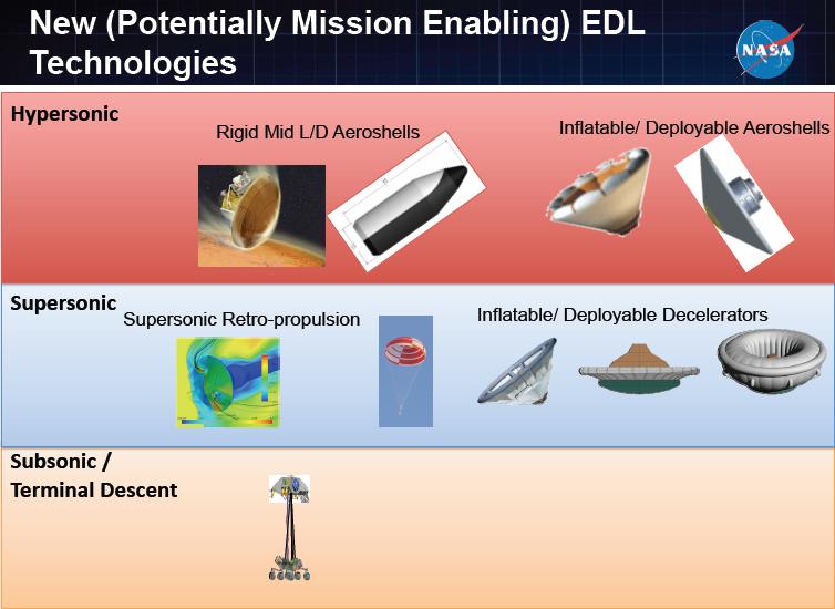
46 A wide Variety of Technologies and Sequences are being developed to deal with E.D.L. (NASA/ Georgia Institute of Tech. diagram)
47 Parachute Problems For a 100 ton cargo lander, a subsonic parachute would need to be ~300 feet in diameter. You may not be able to manufacture such large parachutes. The chute might be too heavy to use effectively. It could take too long to open, and might frequently fail to open properly at all. Parachutes are Expendable - they could not be re-used for the next trip. A Supersonic parachute is less effective at Sub-sonic speeds, since it is slotted to prevent opening damage. You can not make new parachutes at Mars since you do not have the manpower or materials to make them. It is very hard to recover from a parachute failure.
48 Supersonic Decelerators: Ballutes and Hypercones A Ballute is like an inflated semi-rigid parachute used to decelerate at the end of re-entry. Work is beginning on a Ballute-like system called a hypercone that would deploy after speed dropped below about 3250 mph. For a 60 ton vehicle, the wide end of the hypercone would be about 100 feet across. The hypercone fabric still has to be able to withstand heating caused by friction with the air. The Hypercone is hard to deploy and control. Ballutes and Hypercones are expendable only.
49 Combinations are Required if Supersonic Decelerators are used. Once speed drops below Mach 1, a subsonic parachute could be deployed. Below about 1 kilometer, landing rocket engines would be needed to set the lander down gently. This design requires 2 expendable systems, the Hypercone and the subsonic parachute. There is no way to recover and prevent a high speed crash if either the Hypercone or the parachute fails to open properly. A failed chute could also endanger separation of a crew cabin/escape capsule for abort to surface mode.
50 Atmosphere Problems All Mars landers need full heat shields and back shells for re-entry from Mars orbit or directly from solar orbit. We are glad that Mars does have an atmosphere, but if Mars had no atmosphere, it would be much easier to land on; it just would take more fuel. On an airless Mars, descent rocket engines would fire continuously from some point along the descent transfer orbit down to the surface, just like landing on the Moon. With an atmosphere, the descent engines probably cannot fire during the peak period of re-entry. However, they may be able to fire near the end of reentry (at 3250 mph or about local Mach 6.)
51 Supersonic Retro Propulsion This method is called Supersonic Retro Propulsion (SRP). It is now being taken seriously. It requires rocket thrust firing directly through the heat shield and against the supersonic flow of air pressing against the base of the vehicle as it decelerates. The rocket engines must be fixed in position with the nozzle ends flush with and sealed to the heat shield and thus they cannot gimbal for steering. Steering during re-entry and landing must be done by varying the thrust of a set of engines or by using side-mounted small vernier engines.
52 Turbulence vs. Stability Thrusting directly against the air flow may cause extreme turbulence, endangering the vehicles stability, or it may increase OR decrease the braking effect of the heat shield through which the rocket engines are firing, improving OR reducing the deceleration. The rocket engines could be aimed directly forward, or placed along the edges of the heat shield and canted out at an angle from forward. Very little work has ever been done on this method. It requires actual suborbital tests in the Earth s atmosphere to prove which engine configurations and angles may work best.

53 Simulation of Supersonic Retro-Propulsion Center Thrust Diagram showing how central SRP thrust during entry pushes the passive entry drag flow away from the vehicle, reducing drag to near zero. This simulation uses a conical heat shield with a single rocket nozzle in the center with both entry motion and thrust to the left. Cordell, C. E. C.F.D. Verification of Supersonic Retro-Propulsion for a Central and peripheral configuration IEEE Aerospace Conference, Big Sky MT
54 Simulation of Supersonic Retro-Propulsion Peripheral Thrust Magnified diagram showing how a single peripheral thruster during entry allows the passive entry gases closer to the base heat shield, preserving more of the drag forces during SRP. Cordell, C. E. C.F.D. Verification of Supersonic Retro-Propulsion for a Central and peripheral configuration IEEE Aerospace Conference, Big Sky MT

55 Needed: a Suborbital Test of Supersonic Retro Propulsion NASA / Georgia Institute of Tech. diagram Edquist et al
56 Sequences of Descent Technologies: 5 Stages of Deceleration for Mars EDL from 400 km orbit T. Speed to shed = Entry velocity Mars Equator velocity ( = 3360 m/sec) # Orbit to Primary Entry Late Entry Post-Entry Final Descent Re-entry Mach 13 - Mach 6 - Mach Mach 0.2 Mach 6 Mach 2.2 Mach 0.2 Mach m/s m/s m/s -160 m/s -60 m/s Comments gravity Fast with Ballute or Subsonic Rocket multiple (free fall) Heat Shield Hypercone Parachute Power expendables 2. gravity Fast with Supersonic Subsonic Rocket multiple (free fall) Heat Shield Parachute Parachute Power expendables 3. Rocket SLOW, NO Rocket Rocket Rocket Fully Power Heat Shield Power (SRP) Power Power Propulsive 4. gravity Fast with Rocket Rocket Rocket Current (free fall) Heat Shield Power (SRP) Power Power Option 5. gravity Fast with Rocket Supersonic- Rocket Next (free fall) Heat Shield Power (SRP) Subsonic Power Best Parachute Option Velocity values shown depend on the exact simulation scenario being used and are approximate. The Fully Propulsive method results in very little payload delivered to the surface.
57 Banish the Expendable Mentality Think Re-Usable! Current scenarios for Manned Mars landings envision a very large lander which has, inside it, just like a nested Russian doll (Matryoshka), another entire vehicle for the ascent with its own engines, tanks, controls, structure, etc. This means that every trip to the surface requires an entire additional pair of vehicles with all of the descent propellant brought from Earth. It also wastes all of the perfectly good equipment in the descent vehicle or lander. This kind of architecture is only good for the kind of Mars expedition we do not want: the Flags and Footprints style mission, which is financially unsustainable, and leads to the one-way Mars trips currently being proposed by those desperate to see any kind of Manned Mars Mission during their lifetime.

58 Set of Russian Nested Dolls: Matryoshka, a Metaphor for an object with another similar object inside it.


59 Narrow Body Mars Entry Vehicle Using a Rigid Cylindrical Aero-shell which is expended like a launch shroud before landing as shown at right size: 10 x 30 meters Note Entry attitude for Lift and control at center Credit: NASA: Entry, Descent and Landing Systems Analysis Study: Phase 1 Report Thomas A. Zang et al
60 The Case for Re-usable Mars Ferries Fewer ferries would need to be built, launched and shipped from Earth to Low Mars Orbit. Provides additional backup vehicles for rescue. Allows swapping of internal equipment modules from older (retired) units (all designed for rapid swapping). Increases reliability & safety after the first use of vehicle. Simplified designs - most with few or no expendables. Requires an integral (to vehicle) aeroshell for re-entry. Descent structure, engines and tanks can also be used for Ascent, which allows landed mass to be used more than once. Two types: Cargo Ferry & Crew (has crew capsule). Each vehicle would be retired after about 10 flights based on engineering reliability studies of components.
61 Designing a Re-Usable Mars Ferry Re-usable vehicles using SRP can use their engines for: (1) Initial de-orbit burn: (7560 mph 7400 mph) ~ Mach 13 ( ) Passive Atmospheric Entry - Deceleration (Mach 13 Mach 6) (2) Supersonic Retro-propulsion: (~Mach 6 - Mach 0.9) (3) Subsonic Deceleration Mach 0.9 Mach 0.2 (4) Final descent and landing: (Mach 0.2 / 100 mph to surface) (5) Ascent back into Low Mars Orbit. With a fully re-usable vehicle, nothing is thrown away. Hydrogen and oxygen propellants can be created from Mars ice and volatiles, using a nuclear power source and carried back to orbit for use on the next trip down, since there is little cargo other than propellant that needs to go up. Wide base vehicles with lower density slow down more during re-entry and thus need less propellant to land than a narrow base vehicle. All of the propellants needed for Crew and Cargo Descent can be carried UP on ascent. 5 tons of extra propellant can be loaded back into the Propellant Depot in Low Mars Orbit from each Cargo Ferry trip UP for use in Earth Return or access to Phobos and Deimos.
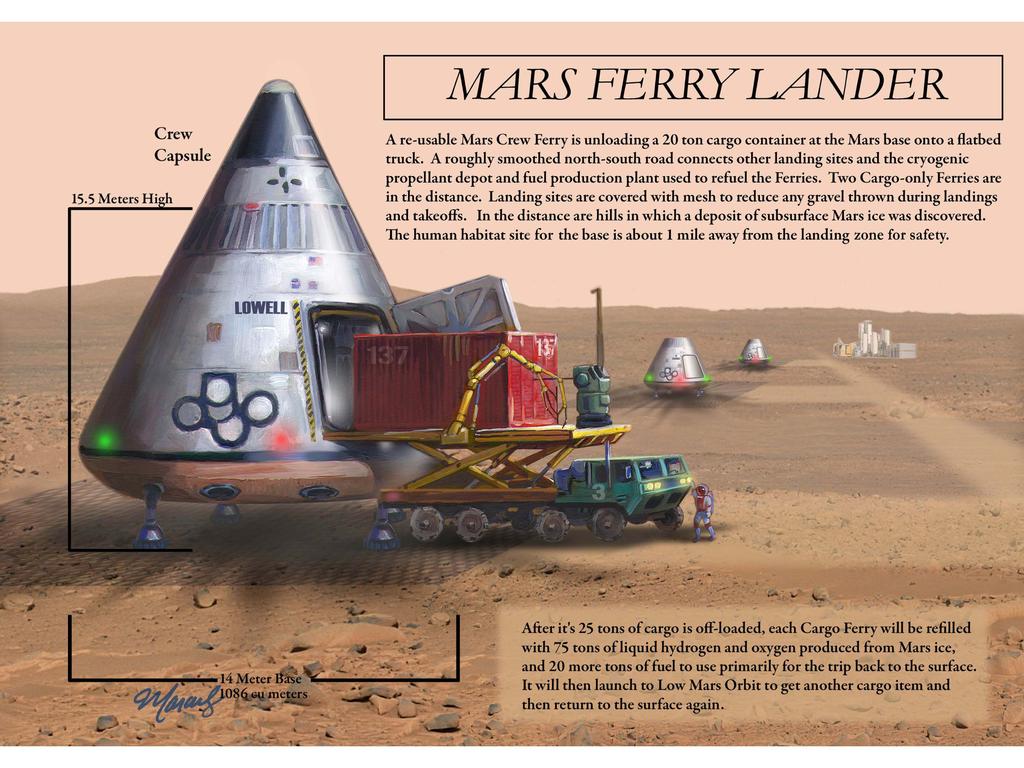
62 A Single Stage to Orbit and Back Vehicle (SSTOAB) for Mars The Mars Ferry is essentially an SSTO for Mars. Mars gravity is 0.38% of Earth s, so achieving low orbit is much easier than on earth - about 2.5 miles per second. This takes only about ¼ of the energy to reach L.E.O. Mars has 1/10 Earth mass, and 8 times lunar mass. If there is no staging, then there is no first stage to recover the entire vehicle goes to the Orbital base and back to the surface base - intact. Much less fuel is needed to land than take off to orbit since normal atmospheric re-entry sheds up to the first 4310 mph ( km/sec) of speed. A cargo ferry would carry 25 tons of modules and equipment down to the surface and 20 tons of propellants back to orbit (15 tons to use for descent and 5 tons for the Depot). A crew ferry (with its 5 ton crew cabin) would carry a crew with 20 tons of cargo down to the surface, and a crew and 15 tons of propellants back to orbit.
63 Discovery of Widespread Sub-Surface Ice on Mars makes propellant production a Non-Exotic operation 20 years ago, we had no knowledge of the widespread existence of Water on Mars in the Form of Sub-surface ice deposits (ice regolith or permafrost), some of them fairly close to the equator. Mars Direct (1989) and related concepts assumed we would bring the hydrogen to make methane fuel from all the way from Earth. Now the hydrogen can be obtained from Mars ice in large enough quantities to use as a fuel directly. Producing propellants at a Mars surface base is NOT an exotic zero-gravity technology that still needs to be developed. All of the individual steps are already performed on Earth every day. This avoids the need to first develop a technology to do it in micro-gravity, and allows a direct process of developing the hardware to do it under Mars conditions. The extraction equipment and cryogenic storage system would be built in package plant modules so that it could be set up easily by tele-operated robots, before crew members descend to the surface. Any Surface Base Site would be influenced by the availability of near-surface ice deposits that can be mined with simple excavation equipment.
64 Steps to create Propellant on Mars a standard sequence Excavate and crush regolith and ice from surface strip mine using excavator and crusher. (The ice may be hard, and may require equipment similar to coal-mining grinders.) Dump pulverized regolith with ice into pressurized hopper and melt the ice using power from a reactor. Drain the water out of the regolith, dispose of the damp regolith, filter and purify the water. Use Electrolysis or other process to produce hydrogen and oxygen gas from Water using electricity from reactor. Liquefy the hydrogen and oxygen using reactor power. Store in insulated tanks and refrigerate using reactor power. Bring propellants to launch site in insulated fuel tanker and fuel the Ascent configuration Ferry.
65 The case for using Cryogenic LOX-Hydrogen propellants instead of LOX-Methane. LOX-Methane propellants, with their lower Specific Impulse, can only carry about 7 tons of cargo (as propellant) UP to orbit in a Ferry vs. about 20 tons for LOX-Hydrogen. Methane would also take more propellants to land on Mars with less payload. This means that most of the propellant mass would still have to be supplied from Earth. Hydrogen is harder to handle and store, but it has now been in use by the US for over 40 years, (2 generations) and we will have over 20 years to ruggedize a LOX-Hydrogen propellant system and automate handling and storage, reducing crew time and increasing reliability. Since we will have the ability to maintain the cryogenic (LOX- H2) propellant supply both in orbit and on the surface, we should use them, due to the huge advantage they give. The Bottom Line: LOX - Hydrogen has massive advantages!

66 Drop-tank 1 ½ stage Mars Ascent Vehicle (MAV) -This Design is Expendable and is carried down on an even larger descent lander (ESA AURORA PROGRAMME)

67 A wider and shorter DC-X-like vehicle could be used as a Mars ferry. Note the fully enclosed base. (Slide Distorted on purpose) Credit: McDonnell Douglas DC-X Image (Artwork)
68 Capsule-shaped landers - a good approximation of a wide body Mars Ferry. NOTE: widths in meters not feet! Capsule shape allows bulky cargo to be landed. (Credit: Georgia Tech J. Christian 06)
 (for SRP, the engines would be close to the outer edge of the base.")
69 Descent Engine Placement for Lander similar to Ferry using S.R.P. (Credit: Georgia Tech J. Christian 06) (for SRP, the engines would be close to the outer edge of the base.) This slide shows placement for 4 engines only
70 Why do we need Mars Ferries? Without re-usable vehicles, you have to bring to Mars Orbit from Earth an expendable lander and all of its propellant for every 20 ton cargo you want to use on the surface, greatly increasing mission cost and mass. With Ferries, you can make repeated trips with Cargo Ferries to bring equipment down for the crew to use. You do need a source (ice) of LOX and Hydrogen on the surface (ISRU) and a large propellant supply buffer in orbit (stored in the Propellant Depot) to operate the Ferries continuously. This means the base site must be where ice exists near the surface underground and can be excavated. For early (Mars Direct style) missions to the surface, fuel producing equipment carried by cargo ferries could be offloaded and set up via tele-operations by crew in LMO. This makes a good case for a Mars Orbit only early mission with a crew, and would allow buildup of a very large propellant supply on the surface before crew arrival on the surface.
71 Mars Ferry: Launch Weight Tonnes Both Cargo & Crew designs mass ~ 70 mt at descent and 125 mt at lift off, with 20 tons total ascent payload and 25 tons for descent. Both vehicles have a base heat shield diameter 14 meters wide. Both Ferry versions have a cargo bay to hold up to 25 tons of large cargo with cargo bay doors that open on the side below the fuel tanks. Both Ferry versions have oversize tanks that can hold 95 tons of propellant (about 75 tons for ascent, about 15 tons for the subsequent descent, and about 5 tons extra for deposit in the propellant depot. (cargo ferry only) CREW AND CARGO FERRY DIFFERENCES: The Crew Ferry has a 5 ton crew cabin / escape capsule on top. It would never separate from the Ferry except in an emergency. The cargo Ferry has no equivalent capsule on top. The Crew Ferry would carry 15 tons of propellants UP as payload in its tanks during a ascent mission, and 20 tons of cargo DOWN during a descent mission. The Cargo Ferry carries (as payload) 20 tons (fuel) UP in its tanks and 25 tons (cargo) DOWN in the cargo bay. Total Ascent and Descent Masses are the same for both Ferries.
72 Mass of Mars Cargo Ferry Configurations The Crew Ferry carries a 5 ton crew capsule and thus carries only 20 tons of payload Down and 15 tons of propellant Up. CONFIGURATION DESCENT ASCENT Component Mass % Mass % Payload - 25 tons Structure - 30 tons Fuel - 15 tons TOTAL: 70 tons 100% 125 t 100% Propellants for the Initial descent trips are supplied from Earth via a Propellant Depot at the man-tended base in a 400 km Low Mars Orbit. 100 % of Descent propellants for subsequent trips are brought back up as payload during the return flights to orbit. Values in Metric Tons
73 Tons to Mars Surface via 10 Expendable Landers vs. 1 Re-usable Ferry in 8 trips 10 Expendable Methane-LOX landers: needed LMO Earth mass: Payload to surface 20 tons x 10 = 200 tons 33 % Lander Structure 15 tons x 10 = 150 tons 25 % Descent Propellant 25 tons x 10 = 250 tons 42 % Total Mass to LMO from Earth: = 600 tons 100 % Ratio of usable payload to other vehicle mass = 200/400 or Re-usable H2-LOX Ferry (8 trips) - LMO mass from Earth: Payload to surface 25 tons x 8 = 200 tons 82 % Lander Structure 30 tons x 1 = 30 tons 12 % Descent Oxygen 13 tons x 1 = 13 tons 5 % Descent Hydrogen ~2 tons x 1 = 2 tons 1 % Total Mass to LMO from Earth = 245 tons 100 % Ratio of usable payload mass to other vehicle mass from Earth = 200/45 or about 4 to 1. Earth source Mass Savings with Ferry = ~355 tons or ~ 60%. 1.8 tons from Earth saved for every 1 ton delivered to the surface.
74 CARGO CONTAINER 4.5 M X 4.5 M X 8M MARS SSTO CARGO FERRY 125-TONNE ASCENT / LAUNCH MASS 70 TON DESCENT MASS DOCKING EQUIPMENT AIRFRAME BASIC STRUCTURE OMS/RCS PROPELLANT TANK(S) LIQUID HYDROGEN TANK Collaborative Research with R. Gopalaswami, Senior Aerospace Engineer, Hyderabad India" RCS THRUSTERS 13.0 OMS ENGINE ELECTRICAL, ELECTRONICS & POWER SYSTEMS 4 X 20 CU.M LOX TANKS THRUST FRAME HEAT SHIELD Descent CARGO CONTAINER 4.5M X 4.5 M X 8M 8 Lox/Hydrogen Liquid Rocket Engines x 20 tonne Thrust Each LANDING GEAR 14.0
75 CARGO CONTAINER 4.5MX4.5MX 8M MARS SSTO CREW FERRY 125-TONNE ASCENT / LAUNCH MASS 70 TON DESCENT MASS CREW CAPSULE (CREW FERRY ONLY) AIRFRAME BASIC STRUCTURE OMS/RCS PROPELLANT TANK(S) LIQUID HYDROGEN TANK Collaborative Research with R. Gopalaswami, Senior Aerospace Engineer, Hyderabad India" DOCKING EQUIPMENT RCS THRUSTERS 17.0 OMS ENGINE ELECTRICAL, ELECTRONICS & POWER SYSTEMS 4 X 20 CU.M LOX TANKS THRUST FRAME HEAT SHIELD Descent CARGO CONTAINER 4.5M X 4.5 M X 8M 8 Lox/Hydrogen Liquid Rocket Engines x 20 tonne Thrust Each LANDING GEAR 14.0
76
77 Discovery of Possible Near-Equatorial ice deposits The current mission design uses a near-equatorial orbit to minimize propellant needs. This provides about 240 meters/second eastward velocity to assist both descent and ascent. Ice cannot exist directly on the surface near the equator since it would evaporate or sublime. Recent reports indicated that sub-surface ice deposits might lie within 25 degrees of the equator. A new paper by David E. Shean * suggests that certain craters close to the equator (in the low-lying Sinus Sabaeus region) may contain buried deposits of ice close to the surface. This would allow using the desired near-equatorial orbit. Base site selection would also be strongly influenced by the existence of other local resources for ISRU and sites of geological and biological interest. * Shean, D. E. (2010), Candidate ice-rich material within equatorial craters on Mars, Geophys. Res. Lett., 37, L24202, doi: /2010gl
78 Examples of Engineering Issues for Ferries & Mars Bases Engineering rigor and math is needed to further verify design details of ferries, propellant mass fraction, required delta-v, tank volumes, etc. Ruggedizing the LOX-H2 system failure mode and fault detection, automated fuel transfer, etc. Do the work on Earth not Mars. How large a power source (nuclear reactor) is needed to support creation and cryogenic storage of the propellant at the surface base? What is the best point for initiating firing of Supersonic Retro-Propulsion (SRP) engines during descent? What is the best angle and arrangement for SRP engines? Exactly how much deceleration can the SRP phase provide? How much deceleration due to drag occurs during the SRP phase? Attitude control for vehicle with fixed engines prove control via throttling or side-mounted small vernier engines. How to handle the start-up/bootstrap phase of transport system and initial flights down when the surface fuel plant is not yet operating. Better estimates of masses, volumes and sizes of cargo items needed on the surface are needed. Minimizing crew time to monitor and control support systems through automation and auto fault detection systems.
79 Crew Ferries with abort to surface and abort to orbit capability To protect crew lives, all crew ferries would use a crew cabin that is also an escape capsule. In case of a catastrophic accident or loss of control, the capsule would separate from the ferry and the crew would descend to the surface or to orbit based on the current velocity. This can be used during descents and ascents. Another crew ferry could be used to rescue a crew stranded too far away from the base to be rescued by a pressurized rover mission. Cargo Ferries could also be designed to carry crew members in an emergency.
80 A Mars Base takes a lot of Equipment Crew Habitat modules that can be connected like space station modules and buried under regolith to protect crew from radiation. A crane and module carrier to unload modules from cargo landers and carry them to the base site. A propellant tanker is needed to store and load fuel, moving it from the surface depot to the launch area. All base sites should be at least 1 km N. or S. of landing and takeoff paths to protect them. You do not want bases, depots or equipment under the flight path. Landing and takeoff sites should be 1/2 km from each other, and also arranged in a North-South line. This implies a north-south main base road.
81 More Base Equipment... A Propellant Depot to store generated fuel. This cannot be next to any landing site. A Mars Volatile Extraction and Propellant.Generating system. (Like Mars Direct). 2-3 Pressurized (Long Distance) Electric Rovers. Several Unpressurized Mars-capable electric ATVs to move within the local base area. 2 separate Energy sources (compact nuclear reactors) to power the base and to provide power to generate and refrigerate Propellants. Communications equipment: short & long range.
82 Even More Base Equipment Surplus of food and consumables for crew use Surplus of spare equipment and spare parts. Surplus of tools, wiring, cables, pipes, ducts, etc. 3D part replication of equipment and parts. Scientific equipment of all types. Deep drilling equipment to extract geological and biological samples and to find buried ice as a water supply. Earth moving and trenching equipment to bury and protect habs, electrical cables and pipes and to excavate the ice deposits to make fuel.
83 Comparison to Support of Antarctic Bases How would we be able (financially) to support our South Pole Antarctic Base if each supply airplane was thrown away after it lands on the ice? A fleet of just 3 cargo ferries, each landing 5 times, could bring down a total of 375 tons of modules, equipment and supplies. This tips the balance of mass brought from Earth towards the supplies and equipment and away from the cargo vehicles and propellants. To do the same using expendable landers would require building and shipping 15 dry landers, some with ascent vehicles, to Mars, as well as all of the propellants for 15 lander flights. A serious scientific Mars base requires a lot of equipment, far more than a few expendable landers could provide.
84 Compare to Original Mars Direct Plan Plan using Ferries is more open-ended, very efficient. Depends primarily on re-usable boosters & vehicles. Uses a much larger crew for safety and more capability. Leaves Earth return vehicles along with Depot in LMO. Provides spare Earth return modules in LMO and spare crew ferries on surface. LMO base is monitored 24/7. Uses Mars Ice to produce propellant for ascent and descent. Allows pre-positioning of redundant vehicles, habitat modules, supplies and fuel on surface. Returns Mars-derived propellants to LMO routinely. Gives crew permanent access to Mars Orbit and its moons. LMO equipment protected from thermal stresses in absence of crew members, allows module monitoring. Crew Modules are buried for full radiation protection. Many Mars Direct concepts still apply to this plan.
85 Benefits of Re-usable Ferry-based Plan Safety in numbers, full medical care for crew. More and faster scientific results per person. More redundancy and safety per person. Permanent surface base established with first mission, and as refuge for the next mission. Greater operational planned use of ISRU. Orbital Base and vehicles left in LMO for use by next expedition equipment health can be monitored from Earth or Mars surface. More flexibility in timing of expeditions. Faster incorporation of new technology & results of Mars operational experience for new missions. Bypasses Flags and Footprint mission phase.
86 What do we need to support Plan? Re-usable, wide (10 meter) HLV boosters to get the large mass of equipment and propellants into LEO and keep the launch costs down. Continued multi-arena Technology Development. Physical Tests to validate SRP. Large scale semi- mass production of Mars equipment and modules to reduce unit costs. Develop near-space infrastructure such as propellant depots to support LEO zone effort. Clear, supportable scientific goals for the Mars expeditions, such as deep drilling for life signs.
87 Lets Keep Going to Mars Our objective is to create a capability for continuing Manned Mars exploration. Let us use the time until the First Mars Expedition making sure that once we go there, we can afford to keep going there. Assuming the first expedition would take place after 2030, we have over 20 years to create Re-usable space vehicles. Surely that is time enough to do it.
88 Engineering Data & Graphs Values shown are current, and will change as improvements are made to this concept. NOTE: Some graphs and tables do not account for the gravitational acceleration during the period in the transfer orbit after the de-orbit burn and before start of entry. This is reflected in a difference in total descent delta-v requirements for the Ferries in those graphs.
89 Cargo Ferry Mass Configurations: the 20 tons of UP Payload is Propellant! Comparison: Hydrogen vs. Methane Vehicle masses Hydrogen-LOX at 465 Isp vs. Methane - LOX at 350 Isp LOX-H2-125 TONS UP LOX-METHANE TONS UP COMPARISON: mass Payload % Payload % 64 % less Structure % Structure % 40 % more Dry Total % Dry Total % 1.5 % less Propellant % Propellant % 56 % more Wet Total % Wet Total % 33 % more Up MASS RATIO 2.5 Up MASS RATIO % more Requirements met with these mass ratios: Delta-V to reach Low Mars Orbit = 4.2 km/sec (margin of 100 meters/sec) 400 km Low Mars Orbit Velocity = 3.36 km/sec (circular) A Methane based system cannot provide full re-supply of DOWN propellants.
90 Cargo Ferry Mass Configurations: Comparison: Hydrogen vs. Methane Vehicle masses 25 vs. 20 tons DOWN CARGO Capacity Hydrogen-LOX at 465 Isp vs. Methane - LOX at 350 Isp down MASS RATIO = 1.39 down MASS RATIO = % more LOX - H2: 70 TONS DOWN LOX-METHANE: 95 TONS DOWN COMPARISON: mass Payload % Payload % 20 % less Structure % Structure % 40 % more Dry Total % Dry Total % 12 % more Propellant % Propellant % 122 % more Wet Total % Wet Total % 38 % more
91 Mars Entry Descent & Landing Sequence Delta-V Requirements met with a mass ratio of 1.39 Velocities at each stage of EDL Delta-V Remain. Velocity Starting V. at 400 mile circular orbit (absolute) 3360 m/s Delta-V. for de-orbit burn from Low Mars Orbit - 82 m/sec 3282 m/s Approximate entry V. at 118 km (absolute velocity) (gravity) 3542 m/s Subtract Mars rotational velocity (not delta-v) m/sec Relative V. to shed to Mars surface at Entry - Total 3302 m/s Approximate Total V. shed from passive entry drag m/sec 896 m/s Delta-V to perform S.R.P. from ~Mach 4 to < Mach m/sec 290 m/s Entry Drag simultaneous with SRP Phase (1/4 of total) m/sec 88 m/s Remaining V. removed during final Landing Phase - 88 m/sec 0 m/s Total passive drag deceleration: 2608 m/sec Total Propulsive Descent Delta-V after de-orbit burn: 694 m/sec Total Propulsive Descent Delta-V (H2-LOX): 776 m/sec Total Delta-V Capacity of descent configuration: 1104 m/sec Reserve Delta-V (for hover and translate margin): 328 m/sec
92 Re-Usable Mars Ferry Mass & Engine Specifications FERRY PARAMETERS max G force allowed G min G force allowed G liftoff (max) thrust req. mt mass init. Ascent mt mass (dry) mt mass init. Descent mt Number of Engines - 8 Max Thrust / engine mt 20 Propellants (Main Engines) - LOX/H2 Mass / engine mt 0.27 Engine: Thrust / Weight ratio est. (full thrust) - 70
93 Sinus Sabaeus Region in Mars with possible ice deposits (Area within dotted red line) Shean, D. E. (2010), Candidate ice-rich material within equatorial craters on Mars, Geophys. Res. Lett., 37, L24202, doi: /2010gl045181
94 h d =D-2h/tanθ Vh MARS SSTO FERRY 125-TONNE LAUNCH MASS VEHICLE DIAMETERS (IN METRES) & VOLUMES (IN CU.M) CORRESPONDING TO EACH HEIGHT (IN METRES) IS SEEN IN THE TABLE Collaborative Research with R. Gopalaswami, Senior Aerospace Engineer, Hyderabad India" 14.0
95 MASS BREAKDOWN (TONNES) OF 14m/125 tonne (Lander: tonne) MARS SSTO FERRY (As a Percentage of SSTO Ferry Dry Structure Mass Tonnes) Margin 15% ENGINE 7% THRUST STRUCTURE 8% HYDROGEN TANK 6% OMS/RCS PROPELLANT 12% POWER SYSTEMS 5% ELECTRICAL & ELECTRONICS SYSTEMS 3% LANDING GEAR 5% HEAT SHIELD 12% Collaborative Research with R. Gopalaswami, Senior Aerospace Engineer, Hyderabad India" LOX TANK 3% BASIC STRUCTURE (UP Vehicle) 4% BACKSHELL STRUCTURE (Lander) 20% ENGINE THRUST STRUCTURE HYDROGEN TANK LOX TANK BASIC STRUCTURE (UP Vehicle) BACKSHELL STRUCTURE (Lander) HEAT SHIELD LANDING GEAR ELECTRICAL & ELECTRONICS SYSTEMS POWER SYSTEMS OMS/RCS PROPELLANT Margin
96 MARS SSTO FERRY : DRY STRUCTURE MASS BREAKDOWN SSTO Element Weight Estimating Relationship Used Reference Mass (Kgm) % age of Allowable Dry Mass Engine T/W= Thrust Structure 0.015* (T/g) T: Newtons Hydrogen Tanks (Main +OMS/RCS) 32.3(V H )^0.795 V H : Cu.m Lox Tanks (Main +OMS/RCS) 27(V O )^0.843 V O : Cu.m BASIC STRUCTURE (UP Vehicle) 0.523(H*n/D)^0.15*q^0.16*Swet^ Basic Structure (DOWN Vehicle) 8.74 %M OL ρ HS * π*d*h HS Heat Shield ρ HS = Specific mass (27 Kgm/m^2) Heat Shield Wetted Area (π*d* h HS ) Landing Gear *M L^ Power Conversion, distribution, OMS (0.135)M & C3 of^0.7213)*l^ OMS/RCS Propellant 5% M L Power System 2.2 % M L 5 Structure Mass Margin (on Kgm Dry Structure) Sum of All Structure Dry components % 1. Sutton GP and Ross Donald M Rocket Propulsion Elements, John Wiley and Sons, Inc, 1976, page 272, Extrapolated from Table Martin JA, An Evaluation of Composite Propulsion Used for Single Stage to Orbit Vehicle with Horizontal Take-Off, NASA TMX 3544, November Marsh CL and Braun RD Fully Propulsive Mars Atmospheric Transit Strategies for High Mass Payload Mission Aerospace conference, 2009 IEEE, 7-14 March 2009 ISBN: Strickland J, Personal Communication 5. Christian JA, Wells G, Lafleur J, Manyapur K, Verges A, Lewis C, Braun RD, Sizing of an Entry, Descent and Landing System for Human Mars Exploration, AIAA Space 2006 Conference September 2006, San Jose, CA. 6. Assumption Collaborative Research with R. Gopalaswami, Senior Aerospace Engineer, Hyderabad India
97 Payload Mass (Tonnes), 20, 16% Collaborative Research with R. Gopalaswami, Senior Aerospace Engineer, Hyderabad India" Dry Structure Mass (Tonnes), 29.75, 24% Propellant Mass (Tonnes), 75.25, 60% DESCENT VEHICLE PARAMETERS INITIAL MASS (IN ORBIT) : TONNES Mission Descent Payload Mass (Tonnes) Structure Mass (Tonnes) Propellant Mass (Tonnes) ASCENT VEHICLE PARAMETERS Launch Mass : 125 Tonnes Propellant Mass (Tonnes) Dry Structure Mass (Tonnes) Payload Mass (Tonnes) Ascent Structure Mass (Tonnes) Ascent Propellant Mass (Tonnes) Payload Mass (Tonnes) = 20 tonnes = Ascent Hydrogen Fuel ferried UP (15 tonnes) tonnes UP cargo/crew & Compartment Lox Mass To be Filed in Orbit (Isp=465 sec) (Tonnes) 0.00 Total propellant Mass for DOWN Ferry (Tonnes) Payload Mass (Tonnes), 25, 36% Propellant Mass (Tonnes) Dry Structure Mass (Tonnes) Payload Mass (Tonnes) Propellant Mass (Tonne 15, 22% Dry Structure Mass (Tonnes), 29.75, 42%
98 MARS SSTO FERRY 125-Tonne Lox/Hydrogen Ascent Vehicle Orbital Parameters & Mass Properties L.M.O. Orbital Height (Kms) 400 L.M.O. Orbit Velocity (Metres/sec) 3366 Ascent Trajectory Loss factor (Assumption) 0.25 Rocket Engine Exhaust Velocity Ve = (9.81 x Isp=465 secs.) 4562 Vehicle Burnout Velocity Vbo=(1+Kl) -1 *Vo (Metres/Sec) 4208 UP Vehicle Mass Ratio R= e^(vbo/ve) 2.52 DOWN Vehicle Mass Ratio 1.27 Ascent / Descent Launch Mass (Tonnes) / (Ascent / Descent ) Payload Mass Fractions (Assumed) / (Ascent / Descent ) Structure Mass Fraction (1/R) - Payload Mass Fraction / (Ascent / Descent ) Propellant Mass Fraction = 1- (Payload + Structure Mass Fraction) / Payload Masses (UP: Propellant + DOWN: Cargo) (Tonnes) / Structure Mass (Tonnes) UP Propellant Mass (Tonnes) DOWN Propellant Mass Collaborative Research with R. Gopalaswami, Senior Aerospace Engineer, Hyderabad India
99 MARS SSTO FERRY 14M / 125 TONNE launch (69.75 Tonne Lander) ENTRY, DESCENT AND LANDING (EDL) PROFILE powered flight - red Collaborative Research with R. Gopalaswami, Senior Aerospace Engineer, Hyderabad India EDL TRAJECTORY (BENCHMARK DATA FROM EXCEL SHEETS) Time (Secs) Delta V (metres/sec) Velocity (Meters/Sec) Absolute Relative Height (Kms) Nadir Angle (Degrees) Propellant Mass (Kgm) Propellant Fraction Peak Thrust (Newtons) Peak Deceleration in Earth 'g' Orbital Velocity (Metres/Sec) PLANETARY ENTRY FROM MARS ORBIT Hoffmann Transfer (Sheet 2) Hoffmann Transfer ΔV= - 84 metres./sec De-orbit (Single Burn) First Burn: Newtons Second Burn: Newtons MARS ATMOSPHERIC ENTRY Non-Propulsive (Sheet 3) Mars Surface Rotational Velocity (Metres/sec) POWERED DESCENT START with Gravity Turn (Sheet 4) POWERED DESCENT END with Gravity Turn Passive Drag: Hover & Touch Down METERS TOTAL DESCENT FLIGHT TIME FROM DE-ORBIT AT 400 KMS 4385 Seconds Total Delta V Hover Reserve Delta V metres/sec/ secs Time with Reserve Propellant
100 Mars SSTO Ferry : Lander Entry, Descent & Landing Trajectory Height above Mars Surface (KMS) Relative Velocity (Metres/sec) Collaborative Research with R. Gopalaswami, Senior Aerospace Engineer, Hyderabad India
101 Mars SSTO Ferry : 14m, 125 tonne (Ascent) ; tonne Descent; Ballistic Coefficient Kgm/m^2 Lander Deceleration & Acceleration During Descent from Atmospheric Interface Decel due to drag (Metres/sec^2) Decel due to Thrust (Metres/sec^2) Accln Due to Gravity (Metres/sec^2) Deceleration & Acceleration (Metres/sec^2) Resultant Deceleration (Metres/sec^2) -6 Height (Kms) -7 Collaborative Research with R. Gopalaswami, Senior Aerospace Engineer, Hyderabad India
102 VALIDATION OF THE ENTRY-DESCENT-LANDING (EDL) TRAJECTORY OF THE MARS SSTO FERRY BY COMPARISON WITH THE EDL TRAJECTORY OF A REFERENCE (MARSH & BRAUN) MARS LANDER VEHICLE Reference Vehicle From Marsh CL and Braun RD Fully Propulsive Mars Atmospheric Transit Strategies for High Mass Payload Mission Aerospace conference, 2009 IEEE, 7-14 March 2009 ISBN: Entry Mass : 60 tonnes Base Diameter: 10 metres Ballistic Coefficient: 477 Kgm/m^2 SSTO Ferry Entry Mass : tonnes Base Diameter: 14 metres Ballistic Coefficient: 382 Kgm/m^2 Collaborative Research with R. Gopalaswami, Senior Aerospace Engineer, Hyderabad India
103 Parameter COMPARISON OF EDL TRAJECTORIES (1) Marsh & Braun Reference Table 5 (Without Heat Rate Constraint) Marsh & Braun Table 6 (With Heat Rate Constraint =0.5 w/cm^2) Phase 1: Planetary Entry Gopalaswami (Heat Rate < 7.12 watts/cm^2) Orbit Height (Kms) Velocity Flight Time (secs) Nadir Angle (degrees) Phase 2: Atmospheric Entry Non-Propulsive Mid-Trajectory Burn Non-Propulsive Height (Kms) Start: 125 End: Start Atmospheric Entry :125 Start First Burn: End Second Burn: End Coasting: Start: End: Velocity (End-Planetary Entry=Start Atmospheric Entry) (m/s) Nadir Angle (Degrees) Flight Time ( ) Collaborative Research with R. Gopalaswami, Senior Aerospace Engineer, Hyderabad India 920
104 COMPARISON OF EDL TRAJECTORIES (2) Parameter Marsh & Braun Reference Table 5 (Without Heat Rate Constraint) Marsh & Braun Table 6 (With Heat Rate Constraint =0.5 w/cm^2) Gopalaswami (Heat Rate < 7.12 watts/cm^2) Height (Kms) Velocity (metres/sec) Phase 3: Gravity Turn at Constant Thrust Start : End Start: End: 0.00 Start: End: Start: End:0.00 Flight Time Phase 4: Hover & Touch Down Height (Meters) N/A N/A Velocity (Metres/sec) N/A N/A Start: End: Start: End: Start: metres End: Metres 1.82 (+Hover Reserve Time secs) Flight Time N/A N/A 8 secs TOTAL FLIGHT TIME FROM DE- ORBIT TO TOUCHDOWN (Secs) Collaborative Research with R. Gopalaswami, Senior Aerospace Engineer, Hyderabad India
105 VALIDATION OF RESULTS Mars OBTAINED SSTO EDL FOR Profile SSTO FERRY (NON- PROPULSIVE Height ENTRY) as a Function WITH A of REFERENCE Relative Velocity VEHICLE Entry Mass: Tonnes; Vehicle Dia.: 14m; Ballistic Coefficient (ALSO WITH NON-PROPULSIVE ENTRY) DIRECT FROM 400 KMS MARS ORBIT Non- Propulsive Reference Vehicle Marsh CL & Braun RD Fully Propulsive Mars Atmospheric Transit Strategies for High-Mass Payload Missions Aerospace conference, 2009 IEEE, 7-14 March 2009 ISBN: Height (Kms) FROM 400KM ORBIT DIRECT FROM INTERPLANETARY TRAJECTORY Direction of Increasing PMF, Shallower Trajectory & Decreasing Heating Rates SSTO Ferry Non-propulsive Entry Heating Rate < 7.12 watts/cm^ GRAVITY TURN INITIATION Relative Velocity (Metres/sec) Reference Vehicle (Non-Propulsive Entry) Heating Rate =7.12 watts/cm^2 Collaborative Research with R. Gopalaswami, Senior Aerospace Engineer, Hyderabad India
106 90 VALIDATION OF Mars RESULTS SSTO OBTAINED Ferry Atmospheric FOR SSTO Entry & FERRY Descent (NON-PROPULSIVE Trajectory ENTRY) WITH A REFERENCE VEHICLE (WITH FULLY-PROPULSIVE ENTRY) Reference Vehicle Fully-Propulsive Entry Figure 8 Marsh & Braun Reference (Lander) Vehicle Fully Propulsive Entry PMF:0.58 M=60T; D=10m Height (Kms) Heating Rate: 0.5 watts/cm^ Direction of Increasing PMF, shallower trajectory and Decreasing Heating Rates Velocity (Metres / sec) SSTO FERRY NON-PROPULSIVE ENTRY PMF: 0.28 M=69.70T; D=14M (Heating Rate < 7.12 watts/cm^2) Collaborative Research with R. Gopalaswami, Senior Aerospace Engineer, Hyderabad India

107 Reference Data for Mars Lander Characteristics Karl T. Edquist, Artem A. Dyakonov, Ashley M. Korzun, Jeremy D. Shidner, Joseph W. Studak, Michael A. Tigges, Devin M. Kipp, and Ravi Prakash, Kerry A. Trumble, and Ian C. Dupzyk Development of Supersonic Retro-Propulsion for Future Mars Entry, Descent, and Landing Systems, American Institute of Aeronautics and Astronautics, AIAA , 10th AIAA/ASME Joint Thermophysics and Heat Transfer Conference, June 2010
Martin J. L. Turner. Expedition Mars. Published in association with. Chichester, UK
 Martin J. L. Turner Expedition Mars Springer Published in association with Praxis Publishing Chichester, UK Contents Preface Acknowledgements List of illustrations, colour plates and tables xi xv xvii
Suitability of reusability for a Lunar re-supply system
 www.dlr.de Chart 1 Suitability of reusability for a Lunar re-supply system Etienne Dumont Space Launcher Systems Analysis (SART) Institut of Space Systems, Bremen, Germany Etienne.dumont@dlr.de IAC 2016
Next Steps in Human Exploration: Cislunar Systems and Architectures
 Next Steps in Human Exploration: Cislunar Systems and Architectures Matthew Duggan FISO Telecon August 9, 2017 2017 The Boeing Company Copyright 2010 Boeing. All rights reserved. Boeing Proprietary Distribution
Massachusetts Space Grant Consortium
 Massachusetts Space Grant Consortium Distinguished Lecturer Series NASA Administrator Dr. Michael Griffin NASA s Exploration Architecture March 8, 2006 Why We Explore Human curiosity Stimulates our imagination
TOWARDS A HEAVY LAUNCHER - PROPULSION SOLUTIONS - A. Souchier - C. Rothmund Snecma Moteurs, Direction Grosse Propulsion à Liquides
 Souchier_2002 TOWARDS A HEAVY LAUNCHER - PROPULSION SOLUTIONS - A. Souchier - C. Rothmund Snecma Moteurs, Direction Grosse Propulsion à Liquides ABSTRACT The Martian human missions will need heavy launchers
On Orbit Refueling: Supporting a Robust Cislunar Space Economy
 On Orbit Refueling: Supporting a Robust Cislunar Space Economy Courtesy of NASA 3 April 2017 Copyright 2014 United Launch Alliance, LLC. All Rights Reserved. Atlas V Launch History ULA s Vision: Unleashing
CHANGING ENTRY, DESCENT, AND LANDING PARADIGMS FOR HUMAN MARS LANDER
 National Aeronautics and Space Administration CHANGING ENTRY, DESCENT, AND LANDING PARADIGMS FOR HUMAN MARS LANDER Alicia Dwyer Cianciolo NASA Langley Research Center 2018 International Planetary Probe
ReachMars 2024 A Candidate Large-Scale Technology Demonstration Mission as a Precursor to Human Mars Exploration
 ReachMars 2024 A Candidate Large-Scale Technology Demonstration Mission as a Precursor to Human Mars Exploration 1 October 2014 Toronto, Canada Mark Schaffer Senior Aerospace Engineer, Advanced Concepts
lights on, down 2 ½ 40 feet, down 2 ½ Kickin up some dust 30 feet, 2 ½ down faint shadow
 lights on, down 2 ½ 40 feet, down 2 ½ Kickin up some dust 30 feet, 2 ½ down faint shadow John Connolly Lunar Lander Project Office 1 Components of Program Constellation Earth Departure Stage Ares V - Heavy
Exploration Architecture Update
 Exploration Architecture Update Doug Cooke Deputy Associate Administrator Exploration Systems Mission Directorate John Connolly Vehicle Engineering and Integration Lunar Lander Project Office March 14,
Lunar Architecture and LRO
 Lunar Architecture and LRO Lunar Exploration Background Since the initial Vision for Space Exploration, NASA has spent considerable time defining architectures to meet the goals Original ESAS study focused
MARS-OZ: A Design for a Simulated Mars Base in the Arkaroola Region
 MARS-OZ: A Design for a Simulated Mars Base in the Arkaroola Region David Willson (david.willson@au.tenovagroup.com) and Jonathan D. A. Clarke (jon.clarke@bigpond.com), Mars Society Australia The centrepiece
Planetary Surface Transportation and Site Development
 Planetary Surface Transportation and Site Development Larry Bell * Sasakawa International Center for Space Architecture (SICSA), Houston, TX 77204-4000 This paper presents considerations and concepts for
Vehicle Reusability. e concept e promise e price When does it make sense? MARYLAND U N I V E R S I T Y O F. Vehicle Reusability
 e concept e promise e price When does it make sense? 2010 David L. Akin - All rights reserved http://spacecraft.ssl.umd.edu 1 Sir Arthur C. Clarke: We re moving from the beer can philosophy of space travel
Lunar Cargo Capability with VASIMR Propulsion
 Lunar Cargo Capability with VASIMR Propulsion Tim Glover, PhD Director of Development Outline Markets for the VASIMR Capability Near-term Lunar Cargo Needs Long-term/VSE Lunar Cargo Needs Comparison with
From MARS To MOON. V. Giorgio Director of Italian Programs. Sorrento, October, All rights reserved, 2007, Thales Alenia Space
 From MARS To MOON Sorrento, October, 2007 V. Giorgio Director of Italian Programs Page 2 Objectives of this presentation is to provide the Lunar Exploration Community with some information and status of
Future NASA Power Technologies for Space and Aero Propulsion Applications. Presented to. Workshop on Reforming Electrical Energy Systems Curriculum
 Future NASA Power Technologies for Space and Aero Propulsion Applications Presented to Workshop on Reforming Electrical Energy Systems Curriculum James F. Soeder Senior Technologist for Power NASA Glenn
BIMODAL NUCLEAR THERMAL ROCKET (BNTR) PROPULSION FOR FUTURE HUMAN MARS EXPLORATION MISSIONS
 PROPULSION FOR FUTURE HUMAN MARS EXPLORATION MISSIONS") BIMODAL NUCLEAR THERMAL ROCKET (BNTR) PROPULSION FOR FUTURE HUMAN MARS EXPLORATION MISSIONS Stan Borowski National Aeronautics and Space Administration Glenn Research Center Cleveland, Ohio Bimodal Nuclear
BIMODAL NUCLEAR THERMAL ROCKET (BNTR) PROPULSION FOR FUTURE HUMAN MARS EXPLORATION MISSIONS Stan Borowski National Aeronautics and Space Administration Glenn Research Center Cleveland, Ohio Bimodal Nuclear
Lunar Surface Access from Earth-Moon L1/L2 A novel lander design and study of alternative solutions
 Lunar Surface Access from Earth-Moon L1/L2 A novel lander design and study of alternative solutions 28 November 2012 Washington, DC Revision B Mark Schaffer Senior Aerospace Engineer, Advanced Concepts
The GHOST of a Chance for SmallSat s (GH2 Orbital Space Transfer) Vehicle
 Vehicle") The GHOST of a Chance for SmallSat s (GH2 Orbital Space Transfer) Vehicle Dr. Gerard (Jake) Szatkowski United launch Alliance Project Mngr. SmallSat Accommodations Bernard Kutter United launch Alliance
The GHOST of a Chance for SmallSat s (GH2 Orbital Space Transfer) Vehicle Dr. Gerard (Jake) Szatkowski United launch Alliance Project Mngr. SmallSat Accommodations Bernard Kutter United launch Alliance
WhirliGig Transfer Vehicle for motor-driven, restartable A.G. Tom Sullivan June, 2002
 WhirliGig Transfer Vehicle for motor-driven, restartable A.G. Tom Sullivan June, 2002 Thrusters (notional) Prop tanks, Ar Rankine Engines (3) Rxtr Radiator, both sides ~25 m Side view 4-5 m Flow of potassium
A LEO Propellant Depot System Concept for Outgoing Exploration
 A LEO Propellant Depot System Concept for Outgoing Exploration Dallas Bienhoff The Boeing Company 703-414-6139 NSS ISDC Dallas, Texas May 25-28, 2007 First, There was the Vision... Page 1 Then, the ESAS
Transportation Options for SSP
 Transportation Options for SSP IEEE WiSEE 2018 SSP Workshop Huntsville, AL 11-13 December 2018 Dallas Bienhoff Founder & Space Architect dallas.bienhoff@csdc.space 571-232-4554 571-459-2660 Transportation
High Power Solar Electric Propulsion for Human Space Exploration Architectures
 High Power Solar Electric Propulsion for Human Space Exploration Architectures IEPC 2011-261 Presented at the 32nd International Electric Propulsion Conference, Wiesbaden Germany September 11 15, 2011
Deployment and Drop Test for Inflatable Aeroshell for Atmospheric Entry Capsule with using Large Scientific Balloon
 , Germany Deployment and Drop Test for Inflatable Aeroshell for Atmospheric Entry Capsule with using Large Scientific Balloon Kazuhiko Yamada, Takashi Abe (JAXA/ISAS) Kojiro Suzuki, Naohiko Honma, Yasunori
Mars Surface Mobility Proposal
 Mars Surface Mobility Proposal Jeremy Chavez Ryan Green William Mullins Rachel Rodriguez ME 4370 Design I October 29, 2001 Background and Problem Statement In the 1960s, the United States was consumed
Blue Origin Achievements and plans for the future
 Blue Origin Achievements and plans for the future Blue Origin A private aerospace manufacturer and spaceflight services company Founded in 2000 by Amazon.com CEO Jeff Bezos Headquarters in Kent (Seattle),
Human Exploration of the Lunar Surface
 International Space Exploration Coordination Group Human Exploration of the Lunar Surface International Architecture Working Group Future In-Space Operations Telecon September 20, 2017 Icon indicates first
Notes: GENERAL DYNAMICS EARLY LUNAR ACCESS [1993]
![Notes: GENERAL DYNAMICS EARLY LUNAR ACCESS [1993]](/thumbs/88/115730710.jpg "Notes: GENERAL DYNAMICS EARLY LUNAR ACCESS [1993]") Notes: file:///f /SPACE Misc/Lunar Explore/Lunar Do...NERAL DYNAMICS EARLY LUNAR ACCESS [1993].htm (1 of 8) [17/03/2005 9:35:03 p.m.] 1.INTRODUCTION EARLY LUNAR ACCESS (ELA) was a "cheaperfasterbetter"
Notes: file:///f /SPACE Misc/Lunar Explore/Lunar Do...NERAL DYNAMICS EARLY LUNAR ACCESS [1993].htm (1 of 8) [17/03/2005 9:35:03 p.m.] 1.INTRODUCTION EARLY LUNAR ACCESS (ELA) was a "cheaperfasterbetter"
Case Study: ParaShield
 Case Study: ParaShield Origin of ParaShield Concept ParaShield Flight Test Wind Tunnel Testing Future Applications U N I V E R S I T Y O F MARYLAND 2012 David L. Akin - All rights reserved http://spacecraft.ssl.umd.edu
Ares V: Supporting Space Exploration from LEO to Beyond
 Ares V: Supporting Space Exploration from LEO to Beyond American Astronautical Society Wernher von Braun Memorial Symposium October 21, 2008 Phil Sumrall Advanced Planning Manager Ares Projects Office
Adrestia. A mission for humanity, designed in Delft. Challenge the future
 Adrestia A mission for humanity, designed in Delft 1 Adrestia Vision Statement: To inspire humanity by taking the next step towards setting a footprint on Mars Mission Statement Our goal is to design an
Reentry Demonstration Plan of Flare-type Membrane Aeroshell for Atmospheric Entry Vehicle using a Sounding Rocket
 AIAA ADS Conference 2011 in Dublin 1 Reentry Demonstration Plan of Flare-type Membrane Aeroshell for Atmospheric Entry Vehicle using a Sounding Rocket Kazuhiko Yamada, Takashi Abe (JAXA/ISAS) Kojiro Suzuki
SABRE FOR HYPERSONIC & SPACE ACCESS PLATFORMS
 SABRE FOR HYPERSONIC & SPACE ACCESS PLATFORMS Mark Thomas Chief Executive Officer 12 th Appleton Space Conference RAL Space, 1 st December 2016 1 Reaction Engines Limited REL s primary focus is developing
LUNAR INDUSTRIAL RESEARCH BASE. Yuzhnoye SDO proprietary
 LUNAR INDUSTRIAL RESEARCH BASE DESCRIPTION Lunar Industrial Research Base is one of global, expensive, scientific and labor intensive projects which is to be implemented by the humanity to meet the needs
NASA Glenn Research Center Intelligent Power System Control Development for Deep Space Exploration
 National Aeronautics and Space Administration NASA Glenn Research Center Intelligent Power System Control Development for Deep Space Exploration Anne M. McNelis NASA Glenn Research Center Presentation
Solar Electric Propulsion Benefits for NASA and On-Orbit Satellite Servicing
 Solar Electric Propulsion Benefits for NASA and On-Orbit Satellite Servicing Therese Griebel NASA Glenn Research Center 1 Overview Current developments in technology that could meet NASA, DOD and commercial
LUNAR DAYLIGHT EXPLORATION Cost Constrained Human and Robotic Exploration Brand Norman Griffin 1 A.M., ASCE
 LUNAR DAYLIGHT EXPLORATION Cost Constrained Human and Robotic Exploration Brand Norman Griffin 1 A.M., ASCE ABSTRACT With 1 rover, 2 astronauts and 3 days, the Apollo 17 Mission covered over 30 km, setup
 Mission to Mars: Project Based Learning Previous, Current, and Future Missions to Mars Dr. Anthony Petrosino, Department of Curriculum and Instruction, College of Education, University of Texas at Austin
IAC-07- A3.I.A.19 A VALUE PROPOSITION FOR LUNAR ARCHITECTURES UTILIZING PROPELLANT RE-SUPPLY CAPABILITIES
 IAC-7- A3.I.A.19 A VALUE PROPOSITION FOR LUNAR ARCHITECTURES UTILIZING PROPELLANT RE-SUPPLY CAPABILITIES James Young Georgia Institute of Technology, United States of America James_Young@ae.gatech.edu
Light-Lift Rocket II
 Light-Lift Rocket I Light-Lift Rocket II Medium-Lift Rocket A 0 7 00 4 MASS 90 MASS MASS This rocket can lift a mission that has up to 4 mass units. This rocket can lift a mission that has up to 90 mass
Phoenix Lander Implications on in situ resource utilization for robotic exploration of Mars
 Phoenix Landing Site May 2008 Phoenix Lander Implications on in situ resource utilization for robotic exploration of Mars LEAG-ICEUM-SRR (2008) Cape Canaveral, FL Robert L. Ash October 29, 2008 Aerospace
The Role of Electric Propulsion in a Flexible Architecture for Space Exploration
 The Role of Electric Propulsion in a Flexible Architecture for Space Exploration IEPC-2011-210 Presented at the 32nd International Electric Propulsion Conference, Wiesbaden Germany C. Casaregola 1, D.
NASA s Choice to Resupply the Space Station
 RELIABILITY SpaceX is based on the philosophy that through simplicity, reliability and low-cost can go hand-in-hand. By eliminating the traditional layers of management internally, and sub-contractors
SPACE LAUNCH SYSTEM. Steve Creech Manager Spacecraft/Payload Integration & Evolution August 29, 2017 A NEW CAPABILITY FOR DISCOVERY
 National Aeronautics and Space Administration 5... 4... 3... 2... 1... SPACE LAUNCH SYSTEM A NEW CAPABILITY FOR DISCOVERY Steve Creech Manager Spacecraft/Payload Integration & Evolution August 29, 2017
Pre-Launch Procedures
 Pre-Launch Procedures Integration and test phase This phase of operations takes place about 3 months before launch, at the TsSKB-Progress factory in Samara, where Foton and its launch vehicle are built.
Lunar and Mars Mission Analysis and Design Using Commercial Launch Systems and the International Space Station
 1 Lunar and Mars Mission Analysis and Design Using Commercial Launch Systems and the International Space Station ARCH 7610: Master s Project Space Architecture ARCH 6398: Special Projects David Smitherman
NEXT Exploration Science and Technology Mission. Relevance for Lunar Exploration
 NEXT Exploration Science and Technology Mission Relevance for Lunar Exploration Alain Pradier & the NEXT mission team ILEWG Meeting, 23 rd September 2007, Sorrento AURORA PROGRAMME Ministerial Council
Extending NASA s Exploration Systems Architecture towards Longterm Crewed Moon and Mars Operations
 SpaceOps 2006 Conference AIAA 2006-5746 Extending NASA s Exploration Systems Architecture towards Longterm Crewed Moon and Mars Operations Wilfried K. Hofstetter *, Paul D. Wooster, Edward F. Crawley Massachusetts
Architecture Options for Propellant Resupply of Lunar Exploration Elements
 Architecture Options for Propellant Resupply of Lunar Exploration Elements James J. Young *, Robert W. Thompson *, and Alan W. Wilhite Space Systems Design Lab School of Aerospace Engineering Georgia Institute
Station for Exploratory Analysis and Research Center for Humanity (SEARCH)
") Station for Exploratory Analysis and Research Center for Humanity (SEARCH) Authors: Jasmine Wong, Matthew Decker, Joseph Lewis, Megerditch Arabian, and Dr. Peter Bishay California State University, Northridge
Station for Exploratory Analysis and Research Center for Humanity (SEARCH) Authors: Jasmine Wong, Matthew Decker, Joseph Lewis, Megerditch Arabian, and Dr. Peter Bishay California State University, Northridge
Mars Aerocapture/Aerobraking Aeroshell Configurations by Abraham Chavez
 Mars Aerocapture/Aerobraking Aeroshell Configurations by Abraham Chavez This presentation provides a review of those studies and a starting point for considering Aerocapture/Aerobraking technology as a
Lunar Missions by Year - All Countries. Mission count dropped as we transitioned from politically driven missions to science driven missions
 n Lunar Missions by Year - All Countries Key: All Mission Attempts Mission Successes Mission count dropped as we transitioned from politically driven missions to science driven missions Capability Driven
Industrial-and-Research Lunar Base
 Industrial-and-Research Lunar Base STRATEGY OF LUNAR BASE CREATION Phase 1 Preparatory: creation of international cooperation, investigation of the Moon by unmanned spacecraft, creation of space transport
H-IIA Launch Vehicle Upgrade Development
 26 H-IIA Launch Vehicle Upgrade Development - Upper Stage Enhancement to Extend the Lifetime of Satellites - MAYUKI NIITSU *1 MASAAKI YASUI *2 KOJI SHIMURA *3 JUN YABANA *4 YOSHICHIKA TANABE *5 KEITARO
ECONOMIC ANALYSIS OF A LUNAR IN-SITU RESOURCE UTILIZATION (ISRU) PROPELLANT SERVICES MARKET:
 PROPELLANT SERVICES MARKET:") ECONOMIC ANALYSIS OF A LUNAR IN-SITU RESOURCE UTILIZATION (ISRU) PROPELLANT SERVICES MARKET: 58 th International Astronautical Congress (IAC) IAC-07-A5.1.03 Hyderabad, India 24-28 September 2007 Mr. A.C.
ECONOMIC ANALYSIS OF A LUNAR IN-SITU RESOURCE UTILIZATION (ISRU) PROPELLANT SERVICES MARKET: 58 th International Astronautical Congress (IAC) IAC-07-A5.1.03 Hyderabad, India 24-28 September 2007 Mr. A.C.
ULA Briefing to National Research Council. In-Space Propulsion Roadmap. March 22, Bernard Kutter. Manager Advanced Programs. File no.
 ULA Briefing to National Research Council In-Space Propulsion Roadmap March 22, 2011 Bernard Kutter Manager Advanced Programs File no. Copyright 2011 United Launch Alliance, LLC. All Rights Reserved. Key
Rocket 101. IPSL Space Policy & Law Course. Andrew Ratcliffe. Head of Launch Systems Chief Engineers Team
 Rocket 101 IPSL Space Policy & Law Course Andrew Ratcliffe Head of Launch Systems Chief Engineers Team Contents Background Rocket Science Basics Anatomy of a Launch Vehicle Where to Launch? Future of Access
Curiosity lands on Mars
 Curiosity lands on Mars Early Monday morning (August 6, 2012), the Mars rover named Curiosity successfully landed on the surface of Mars. The rover launched on November 26 th, 2011 and traveled for 8 ½
Affordable Human Moon and Mars Exploration through Hardware Commonality
 Space 2005 30 August - 1 September 2005, Long Beach, California AIAA 2005-6757 Affordable Human Moon and Mars Exploration through Hardware Commonality Wilfried K. Hofstetter *, Paul D. Wooster., William
SPACE PROPULSION SIZING PROGRAM (SPSP)
") SPACE PROPULSION SIZING PROGRAM (SPSP) Version 9 Let us create vessels and sails adjusted to the heavenly ether, and there will be plenty of people unafraid of the empty wastes. - Johannes Kepler in a
SPACE PROPULSION SIZING PROGRAM (SPSP) Version 9 Let us create vessels and sails adjusted to the heavenly ether, and there will be plenty of people unafraid of the empty wastes. - Johannes Kepler in a
FEDERAL SPACE AGENCY OF RUSSIAN FEDERATION LAVOCHKIN ASSOCIATION PROGRAM OF THE MOON EXPLORATION BY AUTOMATIC SPACE COMPLEXES
 FEDERAL SPACE AGENCY OF RUSSIAN FEDERATION LAVOCHKIN ASSOCIATION PROGRAM OF THE MOON EXPLORATION BY AUTOMATIC SPACE COMPLEXES 2007 CONCEPT 1. The program foresees development of automatic space complexes
A Near Term Reusable Launch Vehicle Strategy
 A Near Term Reusable Launch Vehicle Strategy Ramon L. Chase Warren Greczyn Leon McKinney February 2003 (update) 2900 South Quincy Street Arlington, VA 22202 1 Introduction Provide data that could be used
Deployment and Flight Test of Inflatable Membrane Aeroshell using Large Scientific Balloon
 1 Deployment and Flight Test of Inflatable Membrane Aeroshell using Large Scientific Balloon Kazuhiko Yamada, Takashi Abe (JAXA/ISAS) Kojiro Suzuki, Naohiko Honma, Yasunori Nagata, Masashi Koyama (The
apply to all. space because it is an air-breather. Although from the atmosphere to burn its fuel. This limits
 The next step in becoming a rocket scientist is to apply rocket science and mathematics to the design and construction of actual rockets. There are many tricks of the trade for maximizing thrust and reducing
General spacecraft conceptual designs
 General spacecraft conceptual designs Aaron DeVries Astrum Exploration venera1@live.ca August 27, 2015 Introduction In this paper we will be discussing basic design concepts for a manned mission to the
Name: Space Exploration PBL
 Name: Space Exploration PBL Students describe the history and future of space exploration, including the types of equipment and transportation needed for space travel. Students design a lunar buggy and
Performance Evaluation of a Side Mounted Shuttle Derived Heavy Lift Launch Vehicle for Lunar Exploration
 Performance Evaluation of a Side Mounted Shuttle Derived Heavy Lift Launch Vehicle for Lunar Exploration AE8900 MS Special Problems Report Space Systems Design Lab (SSDL) School of Aerospace Engineering
The European Lunar Lander Mission
 The European Lunar Lander Mission Alain Pradier ASTRA Noordwijk, 12 th April 2011 European Space Agency Objectives Programme Objective PREPARATION FOR FUTURE HUMAN EXPLORATION Lunar Lander Mission Objective
Building an Economical and Sustainable Lunar Infrastructure To Enable Lunar Science and Space Commerce
 Building an Economical and Sustainable Lunar Infrastructure To Enable Lunar Science and Space Commerce Dr. Allison Zuniga, Mark Turner and Dr. Dan Rasky NASA Ames Research Center Space Portal Office Mike
An Innovative Two Stage-to-Orbit Launch Vehicle Concept
 An Innovative Two Stage-to-Orbit Launch Vehicle Concept Ramon L. Chase ANSER L. E. McKinney McKinney Associates H. D. Froning, Jr. Flight Unlimited NASA JPL/MSFC/UAH Twelfth Annual Advance Space Propulsion
WHAT WE WILL DISCUSS IN THIS VIDEO
 WHAT WE WILL DISCUSS IN THIS VIDEO What is Chandrayaan 2 all about? Why is it special? Have we entered the The Asian space race? Where do China, Japan and India stand? What is the importance of the moon?
OMOTENASHI. (Outstanding MOon exploration TEchnologies demonstrated by NAno Semi-Hard Impactor)
") SLS EM-1 secondary payload OMOTENASHI (Outstanding MOon exploration TEchnologies demonstrated by NAno Semi-Hard Impactor) The smallest moon lander launched by the most powerful rocket in the world * Omotenashi
SLS EM-1 secondary payload OMOTENASHI (Outstanding MOon exploration TEchnologies demonstrated by NAno Semi-Hard Impactor) The smallest moon lander launched by the most powerful rocket in the world * Omotenashi
Parametric Design MARYLAND
 Parametric Design The Design Process Earth Orbital/Lunar Orbital Mission Architectures Launch Vehicle Trade Studies Program Reliability Analysis U N I V E R S I T Y O F MARYLAND 2007 David L. Akin - All
A Scalable Orbital Propellant Depot Design
 A Scalable Orbital Propellant Depot Design AE8900 MS Special Problems Report Space Systems Design Lab (SSDL) School of Aerospace Engineering Georgia Institute of Technology Atlanta, GA Author David Street
Abstract. 1 American Institute of Aeronautics and Astronautics
 Enabling Long Duration CisLunar Spaceflight via an Integrated Vehicle Fluid System Michael Holguin, United Launch Alliance (ULA) 9100 E. Mineral Avenue Centennial, CO 80112 Abstract The following paper
An Update on SKYLON. Alan Bond Managing Director & Chief Engineer Reaction Engines Ltd. REACTION ENGINES LTD
 An Update on SKYLON Alan Bond Managing Director & Chief Engineer Reaction Engines Ltd. SKYLON Operations 2 SKYLON 1990 The SKYLON spaceplane the phoenix of HOTOL 1951 Skylon Sculpture Festival of Britain
Cost Estimation and Engineering Economics
 Cost Sources Vehicle-level Costing Heuristics Learning Curves 2 Case Studies Inflation Cost Discounting Return on Investment Cost/Benefit Ratios Life Cycle Costing Cost Spreading 1 2016 David L. Akin -
Venus Entry Options Venus Upper Atmosphere Investigations Science and Technical Interchange Meeting (STIM)
") Venus Entry Options Venus Upper Atmosphere Investigations Science and Technical Interchange Meeting (STIM) January 24, 2013 at the Ohio Aerospace Institute Peter Gage, Gary Allen, Dinesh Prabhu, Ethiraj
Venus Entry Options Venus Upper Atmosphere Investigations Science and Technical Interchange Meeting (STIM) January 24, 2013 at the Ohio Aerospace Institute Peter Gage, Gary Allen, Dinesh Prabhu, Ethiraj
Lunette: A Global Network of Small Lunar Landers
 Lunette: A Global Network of Small Lunar Landers Leon Alkalai and John O. Elliott Jet Propulsion Laboratory California Institute of Technology LEAG/ILEWG 2008 October 30, 2008 Baseline Mission Initial
Fly Me To The Moon On An SLS Block II
 Fly Me To The Moon On An SLS Block II Steven S. Pietrobon, Ph.D. 6 First Avenue, Payneham South SA 5070, Australia steven@sworld.com.au Presented at International Astronautical Congress Adelaide, South
Rocket Activity Advanced High- Power Paper Rockets
 Rocket Activity Advanced High- Power Paper Rockets Objective Design and construct advanced high-power paper rockets for specific flight missions. National Science Content Standards Unifying Concepts and
Preliminary Cost Analysis MARYLAND
 Preliminary Cost Analysis Cost Sources Vehicle-level Costing Heuristics Learning Curves 2 Case Studies Inflation Cost Discounting Return on Investment Cost/Benefit Ratios Life Cycle Costing Cost Spreading
Rocketry and Spaceflight Teleclass Webinar!
 Wednesday August 12, 2015 at 12pm Pacific Name Welcome to the Supercharged Science Rocketry and Spaceflight Teleclass Webinar! You can fill out this worksheet as we go along to get the most out of time
The Common Spacecraft Bus and Lunar Commercialization
 The Common Spacecraft Bus and Lunar Commercialization Alex MacDonald NASA Ames Research Center alex.macdonald@balliol.ox.ac.uk Will Marshall NASA Ames Research Center william.s.marshall@nasa.gov Summary
Supersonic Combustion Experimental Investigation at T2 Hypersonic Shock Tunnel
 Supersonic Combustion Experimental Investigation at T2 Hypersonic Shock Tunnel D. Romanelli Pinto, T.V.C. Marcos, R.L.M. Alcaide, A.C. Oliveira, J.B. Chanes Jr., P.G.P. Toro, and M.A.S. Minucci 1 Introduction
MS1-A Military Spaceplane System and Space Maneuver Vehicle. Lt Col Ken Verderame Air Force Research Laboratory 27 October 1999
 MS1-A Military Spaceplane System and Space Maneuver Vehicle Lt Col Ken Verderame Air Force Research Laboratory 27 October 1999 ReentryWorkshop_27Oct99_MS1-AMSP-SMV_KV p 2 MS-1A Military Spaceplane System
Space Architecture. Master s Thesis Project Jain, Abhishek Dec. 2 nd, 2013
 Space Architecture Master s Thesis Project Jain, Abhishek Dec. 2 nd, 2013 Contents Catalog design for medium lift launch vehicles Catalog application Mission architecture - Lagrange point L2 mission L2
Europa Lander. Mission Concept Update 3/29/2017
 Europa Lander Mission Concept Update 3/29/2017 2017 California Institute of Technology. Government sponsorship acknowledged. 1 Viable Lander/Carrier Mission Concept Cruise/Jovian Tour Jupiter orbit insertion
ENERGIA 1. IDENTIFICATION. 1.1 Name. 1.2 Classification Family : K Series : K-1/SL-17 Version : 4 strap-ons
 1. IDENTIFICATION 1.1 Name 1.2 Classification Family : K Series : K-1/SL-17 Version : 4 strap-ons Category : SPACE LAUNCH VEHICLE Class : Heavy Lift Vehicles (HLV) Type : Expendable Launch Vehicle (ELV)
Long-Range Rovers for Mars Exploration and Sample Return
 2001-01-2138 Long-Range Rovers for Mars Exploration and Sample Return Joe C. Parrish NASA Headquarters ABSTRACT This paper discusses long-range rovers to be flown as part of NASA s newly reformulated Mars
Silicon-Germanium Integrated Electronics for Extreme Environments Applied to the Design of a Lunar Hopper
 Silicon-Germanium Integrated Electronics for Extreme Environments Applied to the Design of a Lunar Hopper Presentation to Leora Peltz (Boeing Phantom Works, Huntington Beach CA, USA) leora.peltz@boeing.com,
FACT SHEET SPACE SHUTTLE EXTERNAL TANK. Space Shuttle External Tank
 Lockheed Martin Space Systems Company Michoud Operations P.O. Box 29304 New Orleans, LA 70189 Telephone 504-257-3311 l FACT SHEET SPACE SHUTTLE EXTERNAL TANK Program: Customer: Contract: Company Role:
Heat Shield Design Project
 Name Class Period Heat Shield Design Project The heat shield is such a critical piece, not just for the Orion mission, but for our plans to send humans into deep space. Final Points Earned Class Participation/Effort
Antares Rocket Launch recorded on 44 1 Beyond HD DDR recorders Controlled by 61 1 Beyond Systems total
 The 1 Beyond ultra-reliable Event DDR and Storage design won the NASA contract to supply the world s largest HD-DDR event recorder which is critical to the new Antares Rocket countdown and launch control
Flight Readiness Review Addendum: Full-Scale Re-Flight. Roll Induction and Counter Roll NASA University Student Launch.
 Flight Readiness Review Addendum: Full-Scale Re-Flight Roll Induction and Counter Roll 2016-2017 NASA University Student Launch 27 March 2017 Propulsion Research Center, 301 Sparkman Dr. NW, Huntsville
AEROSPACE TEST OPERATIONS
 CONTRACT AT NASA PLUM BROOK STATION SANDUSKY, OHIO CRYOGENIC PROPELLANT TANK FACILITY HYPERSONIC TUNNEL FACILITY SPACECRAFT PROPULSION TEST FACILITY SPACE POWER FACILITY A NARRATIVE/PICTORIAL DESCRIPTION
Mass Estimating Relations
 Lecture #05 - September 11, 2018 Review of iterative design approach (MERs) Sample vehicle design analysis 1 2018 David L. Akin - All rights reserved http://spacecraft.ssl.umd.edu Akin s Laws of Spacecraft
Analysis of Launch and Earth Departure Architectures for Near-Term Human Mars Missions
 Analysis of Launch and Earth Departure Architectures for Near-Term Human Mars Missions Wilfried K. Hofstetter 1, Arthur Guest 2, Ryan McLinko 3 and Edward F. Crawley 4 MIT Department of Aeronautics and