Preface. Halmstad, May 2013
|
|
|
- Barrie Floyd
- 6 years ago
- Views:
Transcription
1 EXAMENSARBETE
2 Preface This thesis consists of 15 credits as a final part of a three-year mechanical engineering program at Halmstad University. The project started out in January 2013and come to an end in May The following thesis was made in collaboration with JPL and we want to thank JPL for the opportunity to be a part of this project and special thanks to Drs. Ashitey Trebi-Ollennu for his help and support through the project. We also want to thank Erik Andersson, Per-Johan Bengtsson, Johan Winberg and Tomislav Stanimirovic, which worked alongside with us through this project. Finally we want to thank our supervisors Lars Bååth, professor of photonics, and Pär- Johan Lööf, Lecturer Mechanical Engineering, which contributed with support and guidance to help us get through this project. Halmstad, May 2013 Tobias Johannesson Karl Hansson I
3 Abstract In this thesis we have looked at the possibility of using a rover for deployment of lunar interferometers on the dark side of the moon. This project was made together with two other groups at Halmstad University. The project was divided into three units and we had the main responsibility for the deployment unit on the rover. The deployment unit of the rover is the device that will pick up, carry and roll out the antennas, which is a thin film 1x100 meters rolled up as a roll. The device must work in cooperation with the other units so that the antennas are deployed in a safe and controlled manner. The background of this project is to create a better understanding of the universe, its origin and how it still continues to change. This is made to believe possible by using lunar interferometers that will collect radiation from outer space. The lunar interferometers are placed at the dark side of the moon so that the radiation we humans create will not affect the results. This thesis is issued in collaboration with Jet Propulsion Laboratory (JPL) in Pasadena, California. JPL is a world leading designer and manufacturer of spacerelated products. At the time being JPL has 22 spacecraft and 10 instruments conducting active missions. The focus in this project was to develop a conceptual design of a rover able to deploy the lunar interferometers. The result is a concept created in a 3Denviroment. II
4 Sammanfattning I detta examensarbete har vi tittat på möjligheten att använda en rover för att placera ut radioteleskop på baksidan av månen. Detta gjordes ihop med två andra examensgrupper på Högskolan i Halmstad. Projektet delades upp i tre delar och vi hade huvudansvaret för utplaceringsenheten på rovern. Utplaceringsenheten på roven är den enhet som kommer att hämta, bära och rulla ut antennerna, som är en tunn film på 1x100 meter och upprullade som en rulle. Denna enhet måste i sammarbete med de andra enheterna kunna rulla ut antennerna på ett kontrollerat sätt så att det inte uppstår några spänningar i antennen. Bakgrunden till detta projekt är att få en bätte förståelse för universum, dess uppkomst och hur det än idag fortsätter förändras. Detta trors kunna möjliggöras med hjälp av radioteleskop som tar upp strålning från rymden. Radioteleskopen placeras ut på baksidan av månen för att inte jordens strålning skall påverka resultatet. Examensarbete är utfört i samarbete med Jet Propulsion Laboratory (JPL) i Pasadena, Kalifornien. JPL's är världsledande inom design och konstruktion av rymdrelaterade produkter. För tillfället har JPL 22 rymdfarkoster och 10 instrument i aktiva uppdrag. I detta projekt har vi bara tittat på hur rovern kan komma att se ut och fungera ur ett principkonstruktionsperspektiv. Resultatet är ett koncept skapat i 3D-miljö. III
5 Table of Contents 1. Introduction Background Business presentation Aims and objectives Problem definition Assumptions & delimitations Theoretical framework and references Geotechnical properties Written by Erik Andersson and Per-Johan Bengtsson Lunar landscape Trafficability parameters of lunar soil Wheel sinkage on the lunar surface Radiation Written by Johan Winberg and Tomislav Stanimirovic Solar Cosmic Rays Solar Wind Galactic Cosmic Rays Space radiation effects Shielding Complicating factors Existing rovers Written by Tobias Johannesson and Karl Hansson Lunokhod Lunokhod Lunar Roving Vehicle Sojourner Spirit and Opportunity Curiosity Prerequisite Method Method discussion Methodology of this thesis Results Product definition Product Process Surroundings...23 IV
6 5.1.4 Human interaction Economical aspects Product design specification Deployment strategy Antenna rolls deployed by rover vs. Autonomous antenna rolls Rover as base station vs. External base station Deployment mechanism Specifications Basic Evaluation Detailed evaluation Conclusion Critical review Future work Bibliography Appendix...37 Appendix Appendix Appendix Appendix Appendix V
7 1. Introduction 1. Introduction 1.2 Background The Dark Ages, When the Universe was unlit by any star, represents the last frontier in cosmology. It is the era between the genesis of the cosmic microwave background (CMB) at recombination and the formation of the first star. During the Dark Ages the only detectible signal is likely to be that from neutral hydrogen (H I). The H I will appear in absorption against the CMB and this absorption represents potentially the richest of all data sets in cosmology. The spectral nature of the H I signal allows us to follow the evolution of the Universe as a function of redshift (z). The H I absorption occurs in dark matter-dominated overdensities, locations that will later become the birthplace of the first star, so tracing this evolution will provide crucial insights into the properties of dark matter and potentially reveal aspects of cosmic inflation. Thus any deviation from the expected evolution would be a clean signature of fundamentally new physics. To be able to trace the H I signals a concept for a radio telescope locate on the far side of the Moon, the only site in the solar system shielded from human generated interference and, at night, from solar radio emissions are worked on. The array will observe at 3-30 m wavelengths ( MHz; redshift 15 z 150), and the DALI baseline concept builds on ground-based telescopes operating at similar wavelengths, e.g., Long Wavelength Array (LWA), Murchison Widefield Array (MWA), and Low Frequency Array (LOFAR). Specifically, the fundamental collecting element will be dipoles. The dipoles will be grouped into stations (illustrated in figure 1.1) deployed via rovers over an area of approximately 50 km in diameter to obtain the requisite angular resolution. The stations will be deployed by a rover and there also have to be a transmission hub for sending the signals for correlation to a central processing facility. After sending the correlated output to Earth, analysis would then proceed via standard methods being developed for ground-based arrays. 1

8 1. Introduction Figure 1.1: Illustrating how the interferometer could look on the moon surface 1.3 Business presentation Jet Propulsion Laboratory, JPL, is a world leading designer and manufacturer of space-related products. It is a place where science, technology, and engineering intermix in unique ways. JPL's history can be traced back to the mid-1930s, when a few Caltech students and amateur rocket enthusiasts started tinkering with rockets. After an unintended explosion occurred on campus, the group and its experiments relocated to an isolated area next to the San Gabriel Mountains, the present-day site of JPL. The National Aeronautics and Space Administration, NASA, was founded in October 1958, and JPL was transferred from the Army to the new agency. With this transition JPL began to turn its attention from the rockets themselves to the payloads they would carry. JPL has over the years carried out many successful missions themselves, and together with other spaceorganizations and they have been a contributor to today s understanding of the universe. Their latest successful mission was the Mars-rover Curiosity that landed on Mars August Aims and objectives The aim with this project is to get a better understanding of the universe. By tracing the neutral hydrogen you get a better understanding of how stars evolves so tracing this evolution will provide crucial insights into the properties of dark matter and potentially reveal aspects of cosmic inflation. The objective of this project is to develop a concept of a rover that can withstand the Moons ambient and is able to deploy telescopes on the far side of the Moon. The telescopes goal is to capture neutral hydrogen and send the data back to Earth. 2

9 1. Introduction 1.5 Problem definition As we mentioned earlier the antennas that are supposed to pick up the radiation from outer space must be placed on the dark side of the moon so that the human generated radiation from Earth do not affect the results of the collected data. Today there are no good solutions of how to place the antennas on the dark side of the moon. NASA and JPL have started looking at the possibility to send a rover to accomplish this. Figure 1.2: Illustrating human generated radiation 1.6 Assumptions & delimitations As this project would be way to time consuming in its full extent, and JPL and NASA have an end year of 2030, we had to make some assumptions and delimitations. We are three groups, with two students in every group, and we have divided the rover into three units so one group have primary responsibility for each unit Chassis Johan Winberg and Tomislav Stanimirovic Mobility system Erik Andersson and Per-Johan Bengtsson Deployment unit Tobias Johannesson and Karl Hansson Because of lack of time we decided to only do a conceptual design of the rover with the main focus on how the deployment will work. Since we all are mechanical engineer students we choose to focus on the mechanical aspects of the rover and not look into any electronic components. We also made some assumptions. For instance that the deployment site is prepared when the rover lands, the antenna rolls will be stored in cartridges, landed on the lunar surface and that they will use Atlas V401 rocket system for shipping. 3

10 2. Theoretical framework and references 2. Theoretical framework and references This chapter of the thesis describes the lunar ambient, the lunar surface and its properties, the present radiation and previously constructed rovers. 2.1 Geotechnical properties Written by Erik Andersson and Per-Johan Bengtsson This section explains a number of geotechnical properties of the lunar surface, which are required to make fundamental calculations for a lunar rover. It will also discuss the surface variations, depending on the lunar geography. The data are collected from Lunar Soil Simulation and trafficability parameters (Carrier, 2006) and the Lunar Sourcebook: A User's Guide to the Moon (Grant H. Heiken, David T. Vaniman och Bevan M. French (eds.), 1991), which is a collection of data, gathered during American and Soviet lunar missions Lunar landscape The terrain of the Moon can be divided into highlands and lowlands. The difference in altitude with heights at approximately m and depths at around m is fairly similar to the one on Earth. On the contrary the geology is very different. The Moon has no atmosphere, which makes it exposed for meteor impacts, but eliminates erosion due to weather. A combination of meteor impacts and volcanism has shaped the lunar landscape. This makes the terrain very rough with a few exceptions, which will be presented. The lunar highlands can be seen from Earth as lighter areas, and the lowlands as darker. Early astronomers mistook the highlands and lowlands as lands and seas. Even though we now know that there is not, and never was any oceans on the moon, however we still call the dark areas lunar maria, which is Latin for lunar seas. Lunar maria is lowlands, often impact basins, filled with lava flows. Studies have proven that the lava flows are considerably younger than the basins they reside in, which means that the maria often consists of a relatively flat surfaces, unlike the surrounding landscape (fig ) Figure 2.1: Flat mare (dark area) in Tsiolkovsky crater surrounded by rough terrain (NASA, 1968) 4

11 2. Theoretical framework and references The maria represents about 16 percent of the total lunar surface. About 30 percent of the Earth-facing side is covered with maria, which means that the lunar maria represents less than 1 percent of the far side of the moon. Scientists think this feature is caused due to the lunar crust being thicker on the far side, making it hard for the basalt magma to reach the lunar surface Lunar surface material The entire lunar surface is covered in a material called regolith. It consists of broken rock, soil, dust particles and other related materials. Regolith can also be found on Earth, Mars and other terrestrial planets, but each with its own specific properties. The regolith specific to our moon has a composition of oxygen, silicon, iron, calcium, aluminum, magnesium and other materials in small concentrations. It provides a fairly compact soil with a fine and powdery texture with a density of about 1.5 g/cm 3, and is able to support a wide variety of roving vehicles, which we will confirm with mathematical calculations in the next section. The thickness of the regolith varies between 5 m on mare surfaces, and 10 m in highland areas. Figure 2.2: Footprint in regolith taken on the Apollo 11 mission (NASA, 1969) Trafficability parameters of lunar soil Just after the Apollo 11 mission, NASA issued a request for design proposals for the Lunar Roving Vehicle (LRV), which was used on the Apollo 15, 16 and 17 missions. This initiated a process of soil simulations to find a soil type which matched that of the actual lunar surface. 5
12 2. Theoretical framework and references The Boeing Company, who was the prime contractor for the LRV, defined five sets of soil parameters, as shown in table from the Lunar Soil Simulation and trafficability parameters (Carrier 2006, p. 2) Table 2.1: Soil type parameters (Carrier 2006, p.2) c b and ɸ b define the maximum shear strength of the soil available to drive the wheel. c b is the coefficient of soil/wheel cohesion and its unit is [N/cm 2 ]. ɸ b defines the soil/wheel friction angle (Carrier, 2006). K defines the fraction of the maximum soil shear strength that is actually mobilized due to wheel slippage. K is the coefficient of soil slip and its unit is [cm] (Carrier, 2006). n, k c, and k ɸ define the pressure-sinkage characteristics of the soil under a wheel load. n is the exponent of soil deformation and is dimensionless; k c is the cohesive modulus of soil deformation and its unit is [N/cm 2 ]; k ɸ is the frictional modulus of soil deformation and its unit is [N/cm 3 ] (Carrier, 2006). In 1971, after the completion of the Apollo 15 mission, an extensive evaluation of the LRV's performance was carried out. Costes et al. and Mitchell et al. (1973, 1974) came to the conclusion that soil simulant type B was the best match for actual lunar soil. In correspondence with these conclusions table 9.14 in the Lunar Sourcebook: A User's Guide to the Moon (Carrier et al. 1991, p. 529) lists the current recommended trafficability parameters for lunar soil. Based on this data, we have made the decision to use the parameters of soil type B in our following calculations. 6
13 2. Theoretical framework and references Wheel sinkage on the lunar surface Before initiating any kind of mechanical design, it's essential to establish accurate data regarding identified problem areas. One of these areas is the wheel sinkage on the lunar surface. By using the soil parameters established in the previous section we can create and use mathematical equations and expressions to accurately estimate the actual wheel sinkage of a roving vehicle on the lunar surface. We have made the following calculations: Figure 2.3: Illustrates a wheel sinking into its support surface e.g lunar surface φ = Angle generated due to wheel sinkage θ = 2 φ R = Wheel radius [cm] z = Wheel sinkage [cm] A = Wheel footprint area [cm 2 ] B = Wheel width [cm] ( ) (2.3-1) k = Soil consistency [N/cm 3 ] k c = Cohesive modulus of soil deformation [N/cm 2 ] k ϕ = Frictional modulus of soil deformation [N/cm 3 ] (2.3-2) (2.3-3)* ( ) (2.3-4)* W = Total load per wheel [N] Z = Wheel sinkage [mm] * Lunar Sourcebook: A User's Guide to the Moon (Carrier et al. 1991, p. 526) 7
14 2. Theoretical framework and references Assume a rover with the following specifications: R = 10cm B = 10cm W = 65N ( 160kg total weight on earth) This would generate the following results: ( ) ( ) Regardless of which specifications we use, within reason, we get acceptable results, thanks to the low ground pressure of this type of vehicle. This is what led Carrier to write in the Lunar Sourcebook: From the experience of the Apollo and Lunokhod missions, we now know that almost any vehicle with round wheels will perform satisfactorily on the lunar surface (Carrier et al. 2006, p. 522) 2.2. Radiation Written by Johan Winberg and Tomislav Stanimirovic The radiation that hits the Moon is very diverse and very different from those on the Earth because the Moon lacks both a strong magnetic field and a thick atmosphere. There are three major types of radiation at the Moon: solar cosmic rays, solar wind and galactic cosmic rays. These radiations consist of protons and electrons and the penetration can vary from micrometers to meters depending on their energy and composition (Heiken et al., 1991, p.47) Solar Cosmic Rays Solar-Flare-Associated Particles are produced by the sun. This kind of radiation is also called solar energetic particles or solar cosmic rays (SCR). Because relativistic electrons and nuclei with energies above a few MeV/u are produced only in large fluxes by major flares at the sun, they are present at the Moon only a small fraction of the time. Most of the SCR particles are emitted during the time near solar maximum, which occurs in cycles for 11 years. Solar-cosmic-ray 8
.")
15 2. Theoretical framework and references particles are rarely emitted during the period of the 11-year solar cycle when solar activity is near minimum but can be present near the Moon at any time when the sun is fairly active, usually when the sunspot number is above ~50. However, the sunspot number is only a qualitative indicator of SCR fluxes (Heiken et al., 1991, p.49). These energetic particles are generally a minor concern on the Moon. As we mentioned before a few very large solar particle events can occur each decade. These events would be serious radiation for humans and equipment exposed on the lunar surface, and it is therefore important to predict these SCR events. Data from earlier solar cycles, shown in Illustration I (NASA, 2013), shows that large particle events with above 1010 protons/cm2 are fairly rare. The existing data indicates that there would be several hazardous solar-particle events per solar cycle, and that there is only a period of a few years around solar minimum when such events are unlikely (Heiken et al., 1991, p.52). The prediction shows that the maximum sunspot number in the fall of 2013 will be around 69. Figure 2.4: Past solar cycles and predictions Solar Wind In addition to the radiant energy continuously released from the sun, there is also a steady plasma emission. The composition of the solar wind is not well known, especially for heavier cores. With direct satellite measurements and analyses of artificial materials exposed at the lunar surface it has been possible to characterize large quantity of heavier core in the solar wind. 9
16 2. Theoretical framework and references Galactic Cosmic Rays Galactic cosmic rays are the dominant radiation which must be dealt with. These particles are affected by the Sun s magnetic field which means their average intensity is the highest during periods of low solar activity when the magnetic field is weak and less able to deflect the particles. When the solar wind expands from the sun it carries magnetic fields that cause the GCR particles to lose energy as they penetrate into the solar system. It is shown that the highest GCR fluxes occur during periods of minimum solar activity (Heiken et al., 1991, p.52). This means that the largest possible flux of GCR particles at the Moon would be for a long period of very low solar activity. The radiation damage caused by GCR nuclei is so intense it can cause problems in sensitive electronic components. This requires the use of shielding to protect humans and electronic equipment of the Moon. Shielding of a few g/cm2 is usually adequate to remove most of these highly-ionizing heavy GCR nuclei (Heiken et al., 1991, p.54). There is a study made by Silvestri et al. (2012) where they looked at the ability of different shielding structures to protect electronics from GCR radiation. In the study they used the Columbus shield that reflects the Columbus module used at the International Space Station (ISS) and the Remsim shield designed for future inflatable habitats. In Table I (Silvestri et al., 2012, p.1079) the material, the thickness and the areal density is summarized. To obtain the required iron energy spectrum in the study they used the standard tool for radiation environment and effects calculation, namely CREME96, in the worst case conditions: solar minimum, GEO (Apogee and Perigee km, inclination 0, no magneto-sphereic cutoff). Silvestri et al. (2012, p.1084) came to the conclusion that the behavior of electronic devices below the shield has been found to be dependent on the interplay between different factors: the shielding thickness, the shielding composition, and the device cross section. The sensitive devices such as Commercial off-the Shelf (COTS) are the most affected by the different shielding structure, thickness, and used method. The Soft Error Rate (SER) reduction has been found to be larger for Columbus as compared to Remsim due to the difference in the transmitted secondaries, especially for extremely sensitive devices as mentioned before Space radiation effects Developing reliable space systems for lunar exploration and infrastructure for extended duration operations on the lunar surface requires analysis and mitigation of potential system vulnerabilities to radiation effects on materials and systems (Joseph I, Minow et al., 2007, p.1). 10
17 2. Theoretical framework and references The effects of radiation environment in interplanetary space must be taken into account for spacecraft design. The dominant components of the ionizing radiation environment in interplanetary space are galactic cosmic rays (GCR) and solar cosmic rays (SCR) (Adams, James H., Jr., 2008, p.1). Another event that causes effects on spacecraft materials is meteoric particles. As a result of the space environment factors mentioned above, various physic-chemical processes occur in spacecraft materials and equipment components and lead to the deterioration in their operating parameters. The effects of radiation depend on the type, intensity and energy of the radiation, the type and temperature of the irradiated material and some other factors. More than 50 % of malfunctions in spacecraft equipment are caused by cosmic factors, according to the experts. Radiation effects produced by the action of the fluxes of charged particles on the spacecraft depend on the total absorbed space radiation dose and the dose rate. The most critical effects to microelectronic and optoelectronic components are single charged particles. The effects of these particles depend on the dose rate, because their appearance is related to a large energy release in a restricted volume of material during a short period of time (L.S. Novikov, et al., 2008, p.199) Shielding Shielding is arguably the main countermeasure for the exposure to cosmic radiation during interplanetary exploratory missions. However, shielding of cosmic rays, both of galactic or solar origin, is problematic, because of the high energy of the charged particles involved and the nuclear fragmentation occurring in shielding materials. High-energy radiation is very penetrating. A thin or moderate shielding is generally efficient in reducing the equivalent dose, as the thickness increases, shield effectiveness drops. This is the result of the production of a large number of secondary particles, including neutrons, caused by nuclear interactions of the GCR with the shield (P.Spillantini, et al., 2005, p.14) Complicating factors Radiation effects in spacecraft materials are very complicated. It is difficult to analyze the effects because the compositions and structures of many materials used in the spacecraft constructions are complicated (L.S. Novikov, et al., 2008, p.202). The formation of radiation defects under cosmic ionizing radiation has several special features. The defects produced by different radiation components interact between themselves and also with initial defects of the irradiated structure, with the result that various synergetic effects occur (L.S. Novikov, et al., 2008, p.203). 11

18 2. Theoretical framework and references 2.3. Existing rovers Written by Tobias Johannesson and Karl Hansson This section describes already existing rovers that has driven on another celestial body. It describes how they are constructed and what kind of mission they were made for. The data is collected from different articles and JPL s and NASA s own database Lunokhod 1 The first rover ever to drive on another celestial body was Lunokhod ( moon walker in English) and was constructed in the Soviet Union. The rover was approximately 2,3 meters long, 1,5 meters wide, weight approximately 800 kg and was a remote controlled vehicle that could run at a maximum speed of 2 km/h. It could drive 37 km before it needed recharging. Lunokhod had eight rigid-rim wire mesh wheels with bicycle-type spokes. (Vivake Asnani, 2007) The rover was powered by solar power during the day and at night it parked and relied on thermal energy from polonium-210 radioisotope heater to survive the cold (-150 ). Lunokhods first mission was Luna 17 that launched in November 1970 and after a successful landing on the moon it drove 10,5 km during the following ten months and sent back valuable data concerning the composition of the regolith, close up views and local topography and important engineering measurements of the regolith. (NASA) Lunokhod carried a French-built laser reflector and both the Soviet Union and the French ranged to the reflector during the first lunar night, followed by another success in February After this they never got real contact with the rover until Mars (Murphy, 2010) Figure 2.5: Lunokhod 1 & 2 12
19 2. Theoretical framework and references Lunokhod 2 Two years after Lunokhod first touched the lunar surface the Soviet Union launched mission Luna 21 that delivered a new rover, Lunokhod 2, to the moon. Lunokhod 2 was an upgraded version of Lunokhod1 with better cameras and an improved scientific payload. Like its predecessor it was driven by engineers on Earth during the day and parked at night. Lunokhod explored the moon for about four month and had driven a total distance of 37 km when unfortunately the mission was brought to an early end due to overheating. The two Lunokhod rovers showed the value of robotic explorers on the surface of another celestial body, but it would another 24 years before the next robotic rover, Sojourner, drove on another celestial body, this time Mars. (NASA) Lunar Roving Vehicle Before 1971 the United States had accomplished three successful manned lunar landings and totally explored a distance of approximately 7 km, compared to the Soviet Union that explored approximately 10,5 km with an unmanned rover. In July 1971 the United States launched Apollo 15 that carried America s first vehicle that drove on another celestial body, Lunar Roving vehicle (LRV). The LRV was developed by NASA and built by The Boeing Company. Under development and construction the main concerns were simplicity of design and operation and light weight. The LRV is 3,1 m long, slightly more than 1,83 m wide, 1,14 m high and has a 2,29 m wheelbase. It weighs about 2130 N, including tie down and unloading systems, and can carry a weight of about 4800 N, including the weight of two astronauts and their Portable Life Support System. The LRV has four wheels and each wheel is individually driven by an electrical motor. This makes the vehicle s top speed 9 to 13 km/h depending on the terrain. The rover is powered by two no rechargeable silver-zinc batteries and has two complete battery systems that each can provide power for operation. The LRV is manually operated by one of the two astronauts and normally steered by both front and rear wheels in a double Ackerman arrangement. The wheels are woven of zinc-coated piano wire with a spun aluminum hub and a titanium bump stop. Chevron-shaped treads of titanium are riveted to the wire mesh around each wheel s outer circumference and cover approximately 50 percent of the soil contacting surface. Each wheel weighs 53.3 N. The drive motors are direct-current series, brush-type motors which operate from a nominal voltage of 36 V. Each motor is thermally monitored by an analog temperature measurement from a thermostat at the stator field. In addition each motor contains a thermal switch which closes on increasing temperatures at 204. The basic chassis is fabricated from 2219 aluminum alloy tubing and welded at 13
 Figure 2.")

20 2. Theoretical framework and references the structural joints. The tubular members are milled to minimum thickness consistent with the bending moment and shear diagrams. The chassis is suspended from each wheel by a pair of parallel triangular suspension arms connected between the Rover chassis and each traction drive. (Nicholas C. Costes, 1972) Figure 2.6: Luna Roving Vehicle Sojourner Sojourner is the first unmanned rover to successfully land on another planet. The rover landed on Mars in June of 1997 after spending seven months traveling through space. Sojourner was a part of the NASA Mars Pathfinder mission. Sojourner is a lightweight rover measuring only 0,63 meters long, 0,48 meters wide and with a total weight of 11,5 kg. The small rover is a sixwheeled vehicle of a rocker bogie design that allows driving over rough terrain with a wheel diameter of 0,13 meter and a Figure 2.7: Sojourner top speed of 0,4 meter per min. The rover is powered by a 0,22 sqm solar panel and backed up by a lithium battery. This provides up to 150Whr of energy, normal driving power that is required for a rover this size is 10W. The inner components of the rover are not designed to withstand ambient Mars temperatures of -110 degc during a Martian night. The solution is to place all the 14
21 2. Theoretical framework and references sensitive components inside a Warm Electronics Box, WEB. The WEB houses the computer, batteries, and other vital electronic components. The WEB is designed to protect these components and control their temperature. Thermal control is achieved through the use of gold paint, aerogel insulation, heaters, thermostats, and radiators. This makes sure of a temperature inside the WEB is between -40 degc and 40 degc at all time. (JPL) Spirit and Opportunity In 2000 the decision was made by NASA to send another two rovers to Mars, Spirit and Opportunity. The twin rovers landed successfully on opposite sides of Mars early in The designs of these rovers are based on the earlier Sojourner rover. Some of the carried-over design is the six wheels and a rocker-bogie suspension for driving over rough terrain, solar panels, rechargeable batteries for power and the WEB for housing sensitive components inside the rover. These new rovers are a lot bigger, measuring 1,6 meters long, 2,3 meters wide and with a total weight of 174 kg each. (NASA/JPL, 2005) For driving the twin rovers have six wheels and a rocking-bogie suspension, each wheel have it individual motor for power and the two front wheels and the two rear wheels can turn, this enable the rovers to turn in place. The vehicles have a top speed of 3 m/min. The vehicles are also designed to safely operate at tilts up to 30 degrees but are constructed to withstand tilts up to 45 degrees whiteout falling over. Power to the rover is provided by the solar arrays, generating up to 140 W of power under full Sun conditions. The energy is then stored in rechargeable batteries. The chassis of the rover is based on a box design. The chassis contains the WEB, which works the same way as on the previous rover Sojourner, on top of the WEB is the triangular rover equipment deck, on which is mounted the Pancam mast assembly, high gain, low gain and UHF antennas. Attached to the two forward sides of the equipment deck are solar arrays that are level with the deck and extended outward with the appearance of a pair of swept-back wings. Attached to the lover front of the WEB is the instrument deployment device, a long hinged arm that protrudes in front of the rover. At top of the Pancam mast assembly is the mount for a panoramic camera and cameras for navigations, at a height of about 1,4 meter. 15

22 2. Theoretical framework and references Communications with Earth are in X-band via the high gain directional dish antenna and the low gain omni-directional antenna. Communications with orbiting spacecraft are through the ultra-high frequency, UHF, antenna. Figure 2.8: Spirit Curiosity Curiosity is the forth and biggest rover on Mars as of this day, with roughly the same size as a small car. Curiosity landed safely in august Curiosity also has some key components from its predecessor like the six wheels and a rocking-bogie suspension, a WEB for housing sensitive components, high gain, low gain and UHF antennas for communication, a mast on its equipment deck with a panoramic camera, cameras for navigation and a long arm for executing various experiments on the Martin surface. Curiosity is, as said, roughly the same size as a small car measuring 3 meters long, 2,7 meters wide, 2,2 meters height and a total wait of 900kg. This makes Curiosity by far the biggest unmanned rover to set its wheels on another celestial body. This rover is based on the same box design as its predecessor with a WEB to house sensitive components. Curiosity also carries a science laboratory to be able to carry out more advance experiments. The rover is based on the same six wheels and rocker-bogie suspensions as the earlier rovers, with an individual motor for power to each wheel and steering at the two wheels at the front and the two wheels at the rear. Curiosity has a top speed of 2,4 meters per minute. Curiosity carries a radioisotope power system that generates electricity from a heat of plutonium s radioactive decay. This power source gives the mission an operating lifespan on Mars surface of at least a full Martian year, almost 2 Earth 16

23 3. Prerequisite years. This also providing significantly greater mobility and operational flexibility it also enhanced the science payload capability. (NSSDC) Figure 2.9: Curiosity 3. Prerequisite In order to construct the deployment mechanism, we need to know the size and weight of the antenna rolls. However, this is a problem because there are no antennas made for this purpose and therefore no measurements of their size. To solve this problem we decided to find out, roughly, how big the antennas would be rolled up as a roll and what their weigh would be. We did this by looking up possible materials that the antenna rolls could be made of and assume values that we believe are on the high side of what the values will be when they are constructed. After doing some research for materials that could be relevant we found the material DuPont Kapton. DuPont Kapton is available in many different series and is a polyimide film that works well in environments with large temperature changes. Depending on the class chosen by DuPont Kapton the film is specialized for different things, but common for almost all series is their high temperature resistance and good mechanical properties. DuPont Kapton is today widely used in the areas of aerospace constructions. After looking around on different DuPont Kapton series, we see that the thickness varies between µm. (DUPONT) As the film will contain antenna parts we assume that the film will consist of two layers, where the antenna parts are located between the two layers of DuPont 17

24 3. Prerequisite Kapton films. It is unclear how thick such an antenna part is but assumes the antenna film will have a thickness of approximately 0,1-0,5 mm, including the two layers of DuPont Kapton films, when constructed. When we now have a material and a thickness we are able to do some calculations of what the size and weight would be of the antenna rolls. In order to make the calculations, we first have to build a mathematical formula that describes the size and then we can calculate the weight with help of the density. Figure 3.1: Illustrating looks of antenna roll R r R = Biggest radus r = Shaft Radius t = Thickness on film L = Length on film b = Width on film m = mass on film ρ = Density on film V = volume on film ( ) Values: L = mm b = 1000mm r = 50mm ρ = 1,53 g/cm 3 Thickness, t [mm] 0,1 0,2 0,3 0,4 0,5 Biggest radius, R [mm] 75,4 94,2 109,8 123,4 135,7 Weight, m [kg] 15,3 30,6 45,9 61,2 76,5 Table 3.1: Illustrating how size and weight depends on thickness 18
25 4. Method 4. Method This chapter describes the method used in this thesis Method discussion When working with product development there are many different methods to choose from or combine so that you can work in a structured and controlled manner. There are methods for every step in the development process, from how to choose a project to how to promote a finish product. Since this project and the product that is going to be developed already are decided by JPL there is no need to look into methods for how a project is chosen in this thesis. Since this project is limited to conceptual construction due to a time shortage, there is no need to look in to methods for detailed engineering, manufacturing or how to promote a product. With other words in this thesis there has only been focus on methods for principle construction. Before it was determined which method would be used in this project some different and already created methods was looked into, with focus on their concept construction part. The methods that were looked into were Principkonstruktion by Fredy Olsson (Olsson, 1995), Total design by Stuart Pugh (Pugh, 1990), Product design and development by Kart T. Ulrich and Steven D. Eppinger (Karl T. Ulrich, 2012), Engineering Design by Dym & Little (Clive L. Dym, 2009), Engineering Design Methods by Nigel Cross (Cross, 2008), The Mechanical Design Process by David G. Ullman (Ullman, 2010) and Engineering Design by Dieter & Schmidt (George E. Dieter, 2009). After reading and analyze these different methods you can say that they pretty much are the same. You can divide all these methods into some basic steps, start out with a product definition where all parts that makes up the product are defined, the products main- and sub purpose, the link between the product and humans and who is going to use the product is analyzed and mapped. The next step when the product has been defined is a product study. Are there already similar products on the market, if it is, how are they designed and how do they meet the product specifications. After this is it time to make a product specification for our on product were suitably requirements and desired are selected. 19
26 4. Method When the product specification is done it is time to start a concept generation, also called brainstorming. In the brainstorming you try to come up with as many different concepts as possibly that meet your earlier requirements and desired. When you are satisfied with your brainstorm and the ideas you come up with is it time to continue working with the ideas you got and figure out which one is the better one. It is mainly in this step the different methods divide and are different both in how many evaluations there are to do and how the evaluations are performed Methodology of this thesis This project started out by developing a product specification for the entire product. After this the project was divided into two separate steps. In the first step all three groups worked together to come up with a strategy for the deployment of the radio telescopes. In the second step each group worked separately to design the part they were assigned. In the first step, when the deployment strategy where design the groups decided to use a method that they come up whit themselves. The idea was to come up whit some different concepts for the deployment and then weight their advantages and disadvantages against each other and then chose the concepts with the best results. For the method in the next step it was decided to use the main parts from Osborn's method (Osborn, 1963) with some parts from Fredy Olsson s method (Olsson, 1995) Osborn s method looks like following: 20
27 5. Results Brainstorming Concept Concept Concept Concept Concept Concept Concept Basic evaluation Concept Concept Concept Detailed evaluation Chosen concept Further Development Figure 4.1: Method used in this thesis The parts that were used from Fredy Olsson s method were the how the basic- and detailed evaluation were made. Fredy Olsson has different matrixes for how to weight the different criteria s and then how to get the best concept. (Olsson, 1995) 5. Results This chapter will describe the results of this thesis Product definition This section describes the product definition of the product Product The goal with this project is to construct a roving vehicle that is able to deploy radio antennas on the dark side of the moon. This rover will be designed to operate on the moon, taken into account the temperature differences during day and night and also an array of cosmic rays that is constantly present on the moon. The rover is divided into three product units. The chassis is for stability and protecting vital components, a deployment mechanism for deployment of the antennas and a drive system for mobility. These units are then divided in to product parts. The drive system consists of wheels, suspension and power transfer. The chassis is divided into interior and 21

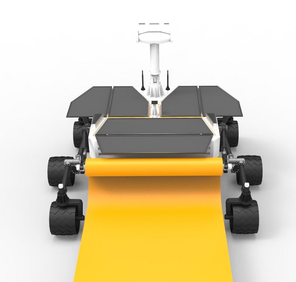
28 5. Results exterior. The interior part is to hold and protect vital inner components and the exterior to provide stability and attachments for outer components. Mission/Project Usage/context Product Units Parts New type of lunar rover Deployment of radio antennas on the lunar surface Lunar rover Drive system Chassis Deployment mechanism Transmission Suspension Wheels Internal chassis External chassis Table 5.1: Product overview Deployment mechanism Process Figure 5.1: Initial Process schematic After deployment from the lunar landing module the rover heads to the stationary rack which holds multiple antenna rolls. This stationary rack will be located near 22

29 5. Results the landing site, prior to this mission. Here it will fetch one antenna rolls. The rover will then need to travel between 100 m and 1 km from the landing site/stationary rack to reach the deployment site. After reaching the destination the rover will deploy each antenna roll in a controlled manner while preventing sideways tension as the film settles on the lunar surface. When the 6 antennas are deployed in the form of a star, as seen in the Figure 5.2, the rover takes place in the middle of the films and acts like a transmission hub. Figure 5.2: Example of antenna deployment Surroundings The rover is placed in a lunar module which will be carried to low earth orbit (LEO) by an Atlas V rocket system. The lunar module will land at the far side of the moon, and deploy the roving vehicle. This rover will then carry out the current mission. During launch, flight and landing the rover can be subjected to forces up to 20 times that of Earth's gravity (20 g) Outside Earth's atmosphere and at the lunar surface, the rover will be exposed to various radiation types. Mainly Solar Cosmic Rays (SCR), Galactic Cosmic Rays (GCR) and solar winds (Section Radiation Environment) A suitable location for this kind of mission could be the lunar mare Tsiolkovsky, at the far side of the moon. Surface conditions of lunar marina are presented in: Section Geotechnical properties' Human interaction The only type of human interaction a mission ready rover of this type will have, is initial loading in lunar module and remote access for managing and data upload/download. 23
30 5. Results Economical aspects The project definition specifies that the economic aspects will not be taken into consideration Product design specification In the list below there is lined up the product design specifications. This design specification tells what the rover must be able to withstand and accomplish on its maiden voyage on the lunar surface. 1. Equipped with elevated camera 2. The rover must house and protect vital electrical components o Communication unit o Remote managing and controlling 3. Rover and lunar landing module must meet the space requirements of the Atlas V 401-4S (4x9.4 m, nose cone) o Compact design 4. Rover design must withstand forces up to 20 g 5. Maximum ground pressure at 3 kpa 6. The rover must withstand the lunar radiation environment o Solar wind o SCR o GCR 7. The rover must withstand temperature differences of ±125 C 8. The antennas shall be deployed in a star-pattern 9. If an antenna malfunctions or is destroyed, a new antenna can be deployed 10. The rover will act as transmission hub for the antennas 11. 8/10 stations must be operational within 90 days 12. 7/10 stations must remain operational after six months 5.3. Deployment strategy This section will describe the deployment strategy Antenna rolls deployed by rover vs. Autonomous antenna rolls To be able to make a decision of which concept is the better we put together the table you see below. In the table we lined up the advantages and the disadvantages of the two different concepts and then weighted them against each other. In the concept deployed by rover the advantages that we can see is that the antenna rolls would be smaller and easier to construct because there is no need to put any equipment inside or around the rolls for deployment. There are also noting 24
31 Weighting Weighting 5. Results that s needed to be protected against the Luna ambient. Another advantage is a more stable deployment. A disadvantage is that the deployment would take longer time because the rover has to deploy the rolls itself. If we look when the rolls are rolled out we see an advantage thanks to the rovers ground clearance, and this is that small stones or other obstacles don t make any problems because the film is rolled out on top of them. In the strategy with autonomous antenna rolls the advantages we can see is the reduced distance the rover will have to travel because it don t have to deploy the rolls itself. This will also save time because when the rover have placed a roll where it supposed to be the autonomously roll rolls out itself meanwhile the rover drive back and pick up next antenna roll. The disadvantages we can see with this strategy are that the rolls will be larger and heavier because they have to some sort of deployment system attach to the rolls or inside the rolls. Some of these components will be hard to shield from the radiations that affect the moon. Another disadvantage is that it will be an unstable deployment because the rolls will have bad ground clearance and if one of the wheels will get stuck by a stone the other will keep drive ant the whole film will get turned. Concept Deployed by rover Autonomous antenna rolls Advantages (1-5) (1-5) Lighter/smaller rolls 5 Shorter distance for rover 1 More stable/secure deployment 5 Save time 1 Lesser chance for film to stuck 4 Disadvantages ( ) ( ) The rover must drive longer -1 Larger, heavier rolls -5 unstable deployment -5 Problem if the film get damaged -4 Little space for construction -4 Radiation shielding -5 Sum: 3,67 Table 5.2: Evaluation of Deployed by rover vs. Autonomous antenna rolls - 3,60 25
32 5. Results After doing this we decided that the strategy where the rover deploys the antenna rolls is the better and a more stable way to deploy the antenna Rover as base station vs. External base station We also have to decide if the rover is to be the base station to each unit or if we should move and place an external base station in the center of each antenna units. This way we would not lock the rover in one place after the antenna units are deployed and we can use the same rover to deploy more antennas units. In the strategy with an external base station an advantage is that one rover can deploy more the one antenna unit, which leads to lesser rovers needed to be constructed and shipped to the moon. This probably also reduces the rovers size. Another advantage is if the rover should break down or get stuck before it completed deploying the antenna rolls in one antenna unit, the base station and the antenna rolls that already are deployed will still work. A disadvantage with only one rover deploying more than one antenna unit is if the rover would break down or get stuck early there will not be any more base stations or antenna rolls deployed. As we can see there are no direct advantages within having the rover as a base station. However there are some disadvantages, the rover would be larger, if the rover brakes down or get stuck before it has completed a full antenna unit nothing will work. We also would have to ship more equipment to the moon. After this we decided that the strategy with an external base station is better and more secure than if the rover is the base station. 26
33 Weighting Weighting 5. Results Concept External base station Rover as base station Advantages (1-5) (1-5) Smaller rover 4 Same rover for several units 5 If rover breaks antennas still works 5 Works as anchor point for antenna rolls 5 Disadvantages ( ) ( ) If rover breaks no more deployment -5 Larger, heavier rover -2 If rover breaks and nothing works -5 One rover for each unit -4 Sum: -0,25-3,67 Table 5.3: Evaluation External Base station vs. Rover as base station Below is a simplified process schematic for how the rover will act when there is an external base stations. Communication unit pick-up Rove to deployment site Deploy communication unit Antenna roll pick-up Antenna deployment Fetch new antenna roll Repeat until all six antennas are deployed Standby for new tasks Figure 5.3: simplified process schematic when an external base station is used 27
34 5. Results 5.4. Deployment mechanism This section will describe the deployment mechanism Specifications In the following table you can see the requirements and desires for the deployment mechanism. The desires are weighted according to Freddy Olsson s method (Olsson, 1995). Design Specification Hold the weight of the rolls Withstand radiation Withstand temperature Withstand launch Requirements [R] / Desired [W] R1 R2 R3 R4 Motions in one plane As few moving parts as possible Simple construction Foldable Table 5.4: Specifications for deployment mechanism D1 D2 D3 D Basic Evaluation In the table in appendix 3 you can see the different design specifications that where put up for the deployment mechanism. There are both requirements and desires. As the requirements are depending on the continued development where choice of thickness and material will be made all our concepts will get the same results and therefore there were no weighting in these. The wishes were weighted between 0-3, where there is good, one is bad and zero does not work. The results is as shown in the table were concept one, two and thirteen is proceeding to 3D CAD construction. In appendix 2 you can see the thirteen different concepts. The first two concepts are fairly different; the third concept is a combination of the first two. 28
 Figure 5.")
 Figure 5.")

35 5. Results Concept one is roughly two jaws which can open and close, when they are closed they create a grip around the antenna roll and hold it sturdy. In the center of the grip there is a roll that will rotate the antenna roll when it is being deployed. (Figure 5.4) Figure 5.4: Concept 1 Concept two is a grip whit only one jaw that creates a grip when it closes and holds it sturdy. This concept has the same strategy for turning the antenna roll while it is deployed. (Figure 5.5) Figure 5.5: Concept 2 Concept thirteen is a combination of concept one and two. It has one moving jaw that will create a sturdy grip of the antenna roll and as in concept one everything is rotating round one point. Also in this concept there is a roll in the center that will rotate the antenna roll ass it is being deployed. (Figure 5.6) Figure 5.6: Concept 13 29
36 5. Results Detailed evaluation To be able to make an informed choice witch of the tree concepts to continue working on there had to be made a detailed evaluation. The method for how this detailed evaluation has been carrying out is taken from Freddy Olsson s method for principle construction. (Olsson, 1995) The results of the detailed evaluations are visibly in the tables below. Where concept thirteen was chosen as the better one. Concept Concept Concept R1 R2 R3 R4 D1 4xFD1 4xFD2 4xFD1 D2 2xFD2 3xFD2 4xFD2 D3 2xFD3 3xFD3 4xFD3 D4 4XFD4 4XFD4 4XFD4 Total 3 3,6 4 Table 5.6: Detailed evaluation Design Specification Requirements [R] / Desired [W] Hold the weight of the rolls R1 Withstand radiation R2 Withstand temperature R3 Withstand launch R4 F Motions in one plane D1 0,3 As few moving parts as possible D2 0,2 Simple construction D3 0,3 Foldable D4 0,2 Table 5.7: Design Specificatons D1 D2 D3 D4 C P F D ,3 D ,2 D ,3 D ,2 Total 20 1 C: correctional factor P: Individual points F: Weight factor Table 5.5: Weight factor of desires 30

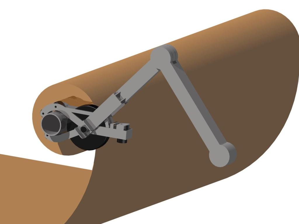
37 5. Results Figure 5.7: A 3D module of final concept In appendix 4 you can see some pictures of how the deployment mechanism is supposed to work. 31
38 6. Conclusion 6. Conclusion When we now are done with the principal construction, as our goal was, and have a concept of how the deployment of the antenna rolls where to be executed on the dark side of the Moon. As you can read earlier in this thesis we have come to the conclusion that of all our concept, concept 13 is the best one and the one the we think as the best potential for continued development. Figure 5.4 shows basic drawing of how the concept works. Basically there is a griping claw, within this claw there are four wheels, three smaller ones that can turn freely and a forth bigger wheel that is connected to an electric motor. This enables the griping claw to pick up and secure a tight grip but at the same time be able to deploy the antenna and unroll it at the right time. The griping claw is attached at the end of an arm that is connected to the rover. This arm has basically two parts with an elbow like joint in the middle. The arm can rotate freely around its connection to the rover and also the griping claw can rotate at the end of the arm. This makes sure that the rover can reach out, pick up and grip the antenna roll carry it to the deployment site and carry out its mission. 32
39 7. Critical review 7. Critical review The goal with this project was to work out a concept idea for a rover that is able to deploy an interferometer on the dark side of the Moon. As you can read earlier in this thesis we have come up with an idée that we are satisfied whit. But the pas six month haven t always been easy. Considering this is a big project the first thing we did was some major delimitations, as the project has moved forward we also have been forced to make more delimitations and some assumptions. The biggest delimitation we did was to only focus on the mechanical part of the rover. This means that we did not at all look into the electronic components of the rover, like the rover s brain, steering or communication. This did not have a major impact on how the project was carried out, we just make sure that there were room for the electronic components. Another big delimitation was also that we only were focusing on a principal construction and there for did not go in to any details. During the project there has come up things along the way that we needed to know, but was not constructed or decided how they were going to work or look yet. So to solve this problem we had to make some assumptions to be able to continue our work. A hard part of this project has been just all the assumptions we have been forced to make during the project. Many of these assumptions is, if you look into it, a project of its own and because of a time shortage we could not go in to them deeper and were forced to make an assumption. This means that the solutions we have come up with is general and some of this is probably to changes in the future if the assumption we made shows to be different. There have been different kinds of assumptions, some of them are to make our work essayer and others to be able to continue at all. An example of a assumptions we made is that the antenna roll already have landed on the Moon when the rover gets there, also that they are in some kind of rack so that they are easy for the rover to pick up. We have not put any time on constructing a rack, but this is something that needs to be constructed alongside whit the rover so that they can operate together. Another example is the antenna rolls itself. Since the exact structure of the material that is going to be used is not decided we cannot yet know what diameter or what weight the rules going to get. So we made an assumption and emanated from that. This means that the concept we picket as the best one maybe will be disregarded later. 33
40 8. Future work We also made the assumption that ground where the antennas are to be rolled out is already prepared. This means that after the rover has landed it can start whit the main mission directly and deployed the interferometers. We made this assumption due to lack of time. If it was not so that the landing site was prepared we would have been forced to construct our rover so that it prepared the site before it started rolling out the antennas or construct a rover only for this. 8. Future work Since this project is fairly big there is a lot of work remaining before there is a rover on the Moon. We decided to only look at the principal construction and the mechanical parts of the rover, this means there are a lot of work remaining whit detail construction and all the electronic components of the rover. The detail construction is a big part of a project and takes a lot of time. This is because in this step you go in to all the details and construct every part that makes the rover. In this step you also need to include the electronic parts and the brain of the rover. Other suggestions to future work is to design and construct the base unit to every interferometer, this needs to be design so it can communicate whit the antennas, the rovers and Earth. It also must be design so that the rover can pick it up and carry it to the deployment site. More suggestions are the antenna rolls itself, and the rack that they are going to be stored and shipped in to the Moon in. There also are needs of some sort of software which enable the rovers to communicate whit Each other, the bas units the rack that s store the antenna roll and Earth. Also a software for the rover itself, since the rover is supposed to work automatically and be able to figure out where to drive and how to get there. When some of the suggestions above are completed it is also time to start with some test here on Earth, to make sure the rover can perform and do what is expected of it. 34
41 9. Bibliography 9. Bibliography Adams, J. H. (2008). Models for galactic cosmic ray and solar energetic particles and their applications to spacecraft design. Carrier, W. D. (2006). Lunar Soil Simulation and Trafficability Pratmeters. Lakeland, FL: Lunar Geotechnical Institute. Clive L. Dym, P. L. (2009). Engineering Design a project-based introduction. John Wiley & Sons Inc. Cross, N. (2008). Engineering Design Methods. John Wiley & Sons Inc. Curiosity, J. (n.d.). JPL Curiosity. Retrieved February 7, 2013, from JPL Curiosity Drozd K, G. R. (1970). Lunar surface engineering properties experiment definition vol.3. NASA. DUPONT. (n.d.). DUPONT. Retrieved February 26, 2013, from George E. Dieter, L. C. (2009). Engineering Design. McGraw-Hill Inc. Heiken H. G, V. T. (1991). Lunar Sourcebook. Cambridge: Press Syndicate of the University of Cambridge. JPL. (n.d.). JPL. Retrieved February 6, 2013, from Karl T. Ulrich, S. D. (2012). Product Design and Development. McGraw-Hill Companies Inc. L.S Novikov, V. N. (2008). Radiation effects on spacecraft material. Minow, J. I., & Blackwell, W. C. (2007). Radiation Enviroments for Lunar Programs. Murphy, T. (2010). Laser ranging to the lost Lunokhod 1 reflector. Icarus 211 (2011). NASA. (n.d.). NASA. Retrieved Mars 06, 2013, from html# NASA. (n.d.). NASA. Retrieved February 11, 2013, from http//: NASA/JPL. (2005). Mars Exploration Rover. NASA Facts. Nicholas C. Costes, J. E. (1972). Mobility preformance of the lunar roving vehicle: Terrestrial studies - Apollo 15 results. Washington D.C: NASA. NSSDC. (n.d.). NSSDC. Retrieved February 8, 2013, from Olsson, F. (1995). Principkonstruktion. Lund: Lunds Tekniska Högskola. Osborn, A. F. (1963). Appliied Imagination: Principles and procedures of creative problem solving. P. Soillantini, M. C.-M. (2005). Shielding from cosmic radiation for interplanetary missions: active and passive methods. 35
42 9. Bibliography Pugh, S. (1990). Total Design. Addison-Wesley Publishers Company Inc. Silvestri M., T. E. (2012). Influence of Spacecraft Shielding Structures on Galactic Cosmic Ray-Induced Soft Error Rate. IEEE TRANSANCTIONS ON NUCLEAR SCIENCE. Ullman, D. G. (2010). The mechanical Design Process. McGraw-Hill Inc. Vivake Asnani, D. D. (2007). The development of wheels for the Lunar Roving Vehicle. Journal of Terramechanics. 36

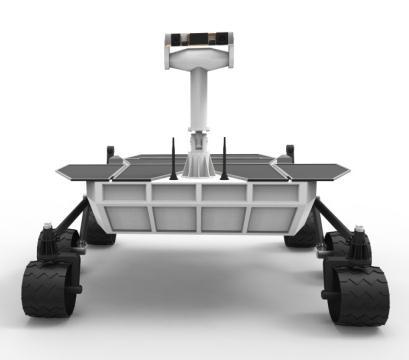
43 10. Appendix 10. Appendix Appendix 1 This is a suggestion of how the rover could look. 37


44 10. Appendix Appendix 2 The Thirteen different Concepts that were brainstormed. Sketch 1 Sketch 2 Sketch 3 Sketch 4 Sketch 5 Sketch 6 Sketch 7 38

45 10. Appendix Sketch 8 Sketch 9 Sketch 10 Sketch 11 Sketch 12 Sketch 13 39
46 10. Appendix Appendix 3 Design Specification Hold the weight of the rolls Requirements [R] / Wishes [W] Sketch 1 Sketch 2 Sketch 3 Sketch 4 Sketch 5 Sketch 6 Sketch 7 Sketch 8 Sketch 9 Sketch 10 Sketch 11 Sketch 12 R Withstand radiation R Withstand temperature R Withstand launch R Motions in one plane W As few moving parts as possible W Simple construction W Foldable W Own thoughts W Summa: Sketch 13 40


47 10. Appendix Appendix 4 Shows how deployment is supposed to work. Start position Collect antenna roll in racket 41

48 10. Appendix Grip antenna roll 42
49 10. Appendix Transportation to deployment site Start deployment 43

50 10. Appendix 44

51 10. Appendix Appendix 5 45
Name: Space Exploration PBL
 Name: Space Exploration PBL Students describe the history and future of space exploration, including the types of equipment and transportation needed for space travel. Students design a lunar buggy and
Light-Lift Rocket II
 Light-Lift Rocket I Light-Lift Rocket II Medium-Lift Rocket A 0 7 00 4 MASS 90 MASS MASS This rocket can lift a mission that has up to 4 mass units. This rocket can lift a mission that has up to 90 mass
Initial Concept Review Team Alpha ALUM Rover (Astronaut Lunar Utility Mobile Rover) Friday, October 30, GMT
 Friday, October 30, GMT") Initial Concept Review Team Alpha ALUM Rover (Astronaut Lunar Utility Mobile Rover) Friday, October 30, 2009 1830-2030 GMT Rover Requirements/Capabilities Performance Requirements Keep up with an astronaut
Initial Concept Review Team Alpha ALUM Rover (Astronaut Lunar Utility Mobile Rover) Friday, October 30, 2009 1830-2030 GMT Rover Requirements/Capabilities Performance Requirements Keep up with an astronaut
Edible Rovers Activity High School Edible Rover Worksheet Geometry Answers
 Edible Rovers Activity High School Edible Rover Worksheet Geometry Answers Instructions You have just been notified that NASA is planning to launch another Mars Rover Mission and you are going to design
 Mission to Mars: Project Based Learning Previous, Current, and Future Missions to Mars Dr. Anthony Petrosino, Department of Curriculum and Instruction, College of Education, University of Texas at Austin
WHAT WE WILL DISCUSS IN THIS VIDEO
 WHAT WE WILL DISCUSS IN THIS VIDEO What is Chandrayaan 2 all about? Why is it special? Have we entered the The Asian space race? Where do China, Japan and India stand? What is the importance of the moon?
Some Thoughts on Simulations in Terramechanics
 Some Thoughts on Simulations in Terramechanics J.Y. Wong Professor Emeritus and Distinguished Research Professor Carleton University and Vehicle Systems Development Corporation Ottawa, Canada Copyright
Mars Surface Mobility Proposal
 Mars Surface Mobility Proposal Jeremy Chavez Ryan Green William Mullins Rachel Rodriguez ME 4370 Design I October 29, 2001 Background and Problem Statement In the 1960s, the United States was consumed
Station for Exploratory Analysis and Research Center for Humanity (SEARCH)
") Station for Exploratory Analysis and Research Center for Humanity (SEARCH) Authors: Jasmine Wong, Matthew Decker, Joseph Lewis, Megerditch Arabian, and Dr. Peter Bishay California State University, Northridge
Station for Exploratory Analysis and Research Center for Humanity (SEARCH) Authors: Jasmine Wong, Matthew Decker, Joseph Lewis, Megerditch Arabian, and Dr. Peter Bishay California State University, Northridge
LUNAR WHEEL TEAM TEAM: ADAM ANDERSON DAN BARRET RICHARD FREDRICKSON KRISTINA LYNN RAMOS ERIC SOLIS. ADVISORS: Dr. COLIN BRITCHER Dr.
 LUNAR WHEEL TEAM TEAM: ADAM ANDERSON DAN BARRET RICHARD FREDRICKSON KRISTINA LYNN RAMOS ERIC SOLIS ADVISORS: Dr. COLIN BRITCHER Dr. SEBASTIAN BAWAB OBJECTIVE design a wheel that would be resistant to the
roving on the moon Leader Notes for Grades 6 12 The Challenge Prepare ahead of time Introduce the challenge (5 minutes)
") for Grades 6 12 roving on the moon Leader Notes The Challenge Build a rubber band-powered rover that can scramble across the room. In this challenge, kids follow the engineering design process to: (1)
for Grades 6 12 roving on the moon Leader Notes The Challenge Build a rubber band-powered rover that can scramble across the room. In this challenge, kids follow the engineering design process to: (1)
Planetary Surface Transportation and Site Development
 Planetary Surface Transportation and Site Development Larry Bell * Sasakawa International Center for Space Architecture (SICSA), Houston, TX 77204-4000 This paper presents considerations and concepts for
Two Related Primary Challenges for Successful Renewed Lunar Exploration
 Two Related Primary Challenges for Successful Renewed Lunar Exploration October 10, 2017 Presented By Ron Creel Retired Apollo Lunar Roving Vehicle Team Member OUTLINE Challenge 1 Coping with Exposure
Brief overview of lunar surface environment Examples of rover types and designs Steering systems Static and dynamic stability
 Brief overview of lunar surface environment Examples of rover types and designs Steering systems Static and dynamic stability 2007 David L. Akin - All rights reserved http://spacecraft.ssl.umd.edu Lunar
Good afternoon. We're going to be talking today about frontiers of imagination in space exploration
 Good afternoon. We're going to be talking today about frontiers of imagination in space exploration First, though, I want to introduce myself. My name is Loretta Hall, and I'm a space buff. I've been a
Study of Flexible Wheels for Lunar Exploration Rovers: Running Performance of Flexible Wheels with Various Amount of Deflection
 Journal of Asian Electric Vehicles, Volume 7, Number 2, December 2009 Study of Flexible Wheels for Lunar Exploration Rovers: Running Performance of Flexible Wheels with Various Amount of Deflection Koiro
Travel: Detailed Flight Plan
 DarkSide Logistics Lunar Spaceport Initiative Travel: Detailed Flight Plan The payload will be launched from Cape Canaveral Air Force Station Launch Complex 46 at 15:59:35 ET on January 25, 2010, using
Lunar Architecture and LRO
 Lunar Architecture and LRO Lunar Exploration Background Since the initial Vision for Space Exploration, NASA has spent considerable time defining architectures to meet the goals Original ESAS study focused
NEXT Exploration Science and Technology Mission. Relevance for Lunar Exploration
 NEXT Exploration Science and Technology Mission Relevance for Lunar Exploration Alain Pradier & the NEXT mission team ILEWG Meeting, 23 rd September 2007, Sorrento AURORA PROGRAMME Ministerial Council
MARS-OZ: A Design for a Simulated Mars Base in the Arkaroola Region
 MARS-OZ: A Design for a Simulated Mars Base in the Arkaroola Region David Willson (david.willson@au.tenovagroup.com) and Jonathan D. A. Clarke (jon.clarke@bigpond.com), Mars Society Australia The centrepiece
SOFT LANDING GET READY AHEAD OF TIME. MATERIALS (per lander) INTRODUCE THE CHALLENGE (10 minutes)
 INTRODUCE THE CHALLENGE (10 minutes)") SOFT LANDING Photo credit: NASA/J CHALLENGE: Design and build an airbag system that can safely land an egg dropped onto the floor. LEARNING GOALS: Science: Force, potential and kinetic energy, and the
SOFT LANDING Photo credit: NASA/J CHALLENGE: Design and build an airbag system that can safely land an egg dropped onto the floor. LEARNING GOALS: Science: Force, potential and kinetic energy, and the
Lunar Driving Simulator History
 1 of 20 Lunar Driving Simulator History Early NASA MSFC/Northrop MOLAB Concept. This vehicle concept evolved from the study contract NAS8-11096 in support of the early Apollo Logistic Support System studies
Lunette: A Global Network of Small Lunar Landers
 Lunette: A Global Network of Small Lunar Landers Leon Alkalai and John O. Elliott Jet Propulsion Laboratory California Institute of Technology LEAG/ILEWG 2008 October 30, 2008 Baseline Mission Initial
Computer-Assisted Induction Aluminum
 Home Computer-Assisted Induction Aluminum Brazing November 11, 2003 Coupled electromagnetic and thermal computer simulation provides a sufficient basis for process optimization and quality improvement
Deployment and Drop Test for Inflatable Aeroshell for Atmospheric Entry Capsule with using Large Scientific Balloon
 , Germany Deployment and Drop Test for Inflatable Aeroshell for Atmospheric Entry Capsule with using Large Scientific Balloon Kazuhiko Yamada, Takashi Abe (JAXA/ISAS) Kojiro Suzuki, Naohiko Honma, Yasunori
Case Studies on NASA Mars Rover s Mobility System
 Case Studies on NASA Mars Rover s Mobility System Shih-Liang (Sid) Wang 1 Abstract Motion simulation files based on Working Model 2D TM are developed to simulate Mars rover s mobility system. The rover's
The Study of Locomotion of Small Wheeled Rovers: The MIDD Activity
 The Study of Locomotion of Small Wheeled Rovers: The MIDD Activity L. Richter 1, M.C. Bernasconi 2, P. Coste 3 1: Institute of Space Simulation, D-51170 Cologne, Germany 2: Contraves Space, CH-8052 Zurich,
Success of the H-IIB Launch Vehicle (Test Flight No. 1)
") 53 Success of the H-IIB Launch Vehicle (Test Flight No. 1) TAKASHI MAEMURA *1 KOKI NIMURA *2 TOMOHIKO GOTO *3 ATSUTOSHI TAMURA *4 TOMIHISA NAKAMURA *5 MAKOTO ARITA *6 The H-IIB launch vehicle carrying
53 Success of the H-IIB Launch Vehicle (Test Flight No. 1) TAKASHI MAEMURA *1 KOKI NIMURA *2 TOMOHIKO GOTO *3 ATSUTOSHI TAMURA *4 TOMIHISA NAKAMURA *5 MAKOTO ARITA *6 The H-IIB launch vehicle carrying
Rocket Activity Advanced High- Power Paper Rockets
 Rocket Activity Advanced High- Power Paper Rockets Objective Design and construct advanced high-power paper rockets for specific flight missions. National Science Content Standards Unifying Concepts and
Lunar Escape: Development of Astronaut Recovery Rover Program
 Lunar Escape: Development of Astronaut Recovery Rover Program Nicholas Wade-Mayhue, Dan Janke, Kyle Kilgore, Mohammed Alzohay, Samad Qureshi Colorado School of Mines Advisor: Dr. Knecht nwademay@mines.edu
Adrestia. A mission for humanity, designed in Delft. Challenge the future
 Adrestia A mission for humanity, designed in Delft 1 Adrestia Vision Statement: To inspire humanity by taking the next step towards setting a footprint on Mars Mission Statement Our goal is to design an
SAE Baja - Drivetrain
 SAE Baja - Drivetrain By Ricardo Inzunza, Brandon Janca, Ryan Worden Team 11A Concept Generation and Selection Document Submitted towards partial fulfillment of the requirements for Mechanical Engineering
Rediscovery of the Lunokhod 1 Reflector
 Rediscovery of the Lunokhod 1 Reflector What it means for Lunar Ranging Science Tom Murphy (PI) Eric L. Michelsen UCSD and the APOLLO Collaboration Background photo: Dan Long Introduction to APOLLO APOLLO
SAE Mini BAJA: Suspension and Steering
 SAE Mini BAJA: Suspension and Steering By Zane Cross, Kyle Egan, Nick Garry, Trevor Hochhaus Team 11 Progress Report Submitted towards partial fulfillment of the requirements for Mechanical Engineering
Industrial-and-Research Lunar Base
 Industrial-and-Research Lunar Base STRATEGY OF LUNAR BASE CREATION Phase 1 Preparatory: creation of international cooperation, investigation of the Moon by unmanned spacecraft, creation of space transport
Chapter 3 Solar PV Panel: Components Details and Fabrication
 Chapter 3 Solar PV Panel: Components Details and Fabrication Background After deciding the idea of position of Solar PV Panel, the next step is to conceptualize and fabricate one module and deploy it on
Performance Evaluation of Wheeled Rover by Analysis and Test
 Performance Evaluation of Wheeled Rover by Analysis and Test Gaurav Sharma, Srividhya G., Shamrao, K. Balaji, G. Nagesh, C.D. Sridhara Abstract Rovers provide a mobile platform for exploring planetary
Massachusetts Space Grant Consortium
 Massachusetts Space Grant Consortium Distinguished Lecturer Series NASA Administrator Dr. Michael Griffin NASA s Exploration Architecture March 8, 2006 Why We Explore Human curiosity Stimulates our imagination
Safety Assessment for secondary payloads launched by Japanese Expendable Launch Vehicle
 Safety Assessment for secondary payloads launched by Japanese Expendable Launch Vehicle 6 th IAASS(International Association for the Advancement of Space Safety) Safety is Not an Option Montreal, Canada
SAE Mini Baja: Suspension and Steering
 SAE Mini Baja: Suspension and Steering Project Proposal Zane Cross, Kyle Egan, Nick Garry, Trevor Hochhaus NAU December 3, 2014 Overview 2 Problem Definition and Project Plan Concept Generation Design
THE SIMULATION OF ONE SIDE OF TETRAHEDRON AIRBAGS IMPACT ATTENUATION SYSTEM
 THE SIMULATION OF ONE SIDE OF TETRAHEDRON AIRBAGS IMPACT ATTENUATION SYSTEM Zhuo Wu (1) (1) Beijing Institution of Space Mechanics and Electrics, PB-9201-3, Beijing, China, Email:wuzhuo82@gmail.com ABSTRACT
Planetary Roller Type Traction Drive Unit for Printing Machine
 TECHNICAL REPORT Planetary Roller Type Traction Drive Unit for Printing Machine A. KAWANO This paper describes the issues including the rotation unevenness, transmission torque and service life which should
White Paper. How Do I Know I Can Rely on It? The Business and Technical Cases for Solar-Recharged Video Surveillance Systems
 White Paper How Do I Know I Can Rely on It? The Business and Technical Cases for Solar-Recharged Video Surveillance Systems Introduction Remote cameras are a security professional s eyes at the edges of
ANALYSIS ON MECHANICAL PARAMETERS OF LUNAR ROVER WHEEL
 ANALYSIS ON MECHANICAL PARAMETERS OF LUNAR ROVER WHEEL 1,2 DAWEI JIN, 1 JIANQIAO LI, 3 JIANXIN ZHU, 3 CHUNHUA ZHANG 1 Key laboratary of Bionic Engineering (Ministry of Education), Jilin University, Changchu
Reentry Demonstration Plan of Flare-type Membrane Aeroshell for Atmospheric Entry Vehicle using a Sounding Rocket
 AIAA ADS Conference 2011 in Dublin 1 Reentry Demonstration Plan of Flare-type Membrane Aeroshell for Atmospheric Entry Vehicle using a Sounding Rocket Kazuhiko Yamada, Takashi Abe (JAXA/ISAS) Kojiro Suzuki
Soviet Lunokhod 1 and 2 missions and things around
 Soviet Lunokhod 1 and 2 missions and things around Alexander Basilevsky Vernadsky Institute of Geochemistry and Analytical Chemistry Russian Academy of Sciences, Moscow, Russia and Department of Geological
Martin J. L. Turner. Expedition Mars. Published in association with. Chichester, UK
 Martin J. L. Turner Expedition Mars Springer Published in association with Praxis Publishing Chichester, UK Contents Preface Acknowledgements List of illustrations, colour plates and tables xi xv xvii
Long-Range Rovers for Mars Exploration and Sample Return
 2001-01-2138 Long-Range Rovers for Mars Exploration and Sample Return Joe C. Parrish NASA Headquarters ABSTRACT This paper discusses long-range rovers to be flown as part of NASA s newly reformulated Mars
Cooperative EVA/Telerobotic Surface Operations in Support of Exploration Science
 Cooperative EVA/Telerobotic Surface Operations in Support of Exploration Science David L. Akin http://www.ssl.umd.edu Planetary Surface Robotics EVA support and autonomous operations at all physical scales
Lockheed Martin. Team IDK Seung Soo Lee Ray Hernandez Chunyu PengHarshal Agarkar
 Lockheed Martin Team IDK Seung Soo Lee Ray Hernandez Chunyu PengHarshal Agarkar Abstract Lockheed Martin has developed several different kinds of unmanned aerial vehicles that undergo harsh forces when
Railway Technical Web Pages
 Railway Technical Web Pages Archive Page Vehicle Suspension Systems Introduction Almost all railway vehicles use bogies (trucks in US parlance) to carry and guide the body along the track. Bogie suspension
Electrical Engineering Within a Robotic System
 Electrical Engineering Within a Robotic System Carli Hand Fall, 2016 Synopsis The NASA Robotics Mining Competition (RMC) is held every year at Kennedy Space Center, Florida. Fifty universities assemble
Spacecraft Power Systems
 Spacecraft Power Systems The Generation and Storage of Electrical Power D. B. Kanipe Aero 401 February 9, 2016 Power Systems Batteries Solar Cells + Batteries Fuel Cells RTG Nuclear Reactors? Functions
Landing Targets and Technical Subjects for SELENE-2
 Landing Targets and Technical Subjects for SELENE-2 Kohtaro Matsumoto, Tatsuaki Hashimoto, Takeshi Hoshino, Sachiko Wakabayashi, Takahide Mizuno, Shujiro Sawai, and Jun'ichiro Kawaguchi JAXA / JSPEC 2007.10.23
NASA Glenn Research Center Intelligent Power System Control Development for Deep Space Exploration
 National Aeronautics and Space Administration NASA Glenn Research Center Intelligent Power System Control Development for Deep Space Exploration Anne M. McNelis NASA Glenn Research Center Presentation
Heat Shield Design Project
 Name Class Period Heat Shield Design Project The heat shield is such a critical piece, not just for the Orion mission, but for our plans to send humans into deep space. Final Points Earned Class Participation/Effort
Seminar 12! The Future of Space Flight! Spacecraft Power & Thermal Control!
 Seminar 12! The Future of Space Flight! Spacecraft Power & Thermal Control! Robert Stengel! FRS 112, From the Earth to the Moon! Princeton University, 2015! " NASA s Strategic Direction! Rationales and
M:2:I Milestone 2 Final Installation and Ground Test
 Iowa State University AerE 294X/AerE 494X Make to Innovate M:2:I Milestone 2 Final Installation and Ground Test Author(s): Angie Burke Christopher McGrory Mitchell Skatter Kathryn Spierings Ryan Story
w. David Carrier, III
 BOARD OF TRUSTEES Brig. Gen. Charles M. Duke, Jr. USAF Ret. Apollo 16 Astronaut Dr. Valery V. Gromov Mobile Vehicle Engineering St. Petersburg, Russia Dr. Grant Heiken University or California Los Alamos
Page 1. Design meeting 18/03/2008. By Mohamed KOUJILI
 Page 1 Design meeting 18/03/2008 By Mohamed KOUJILI I. INTRODUCTION II. III. IV. CONSTRUCTION AND OPERATING PRINCIPLE 1. Stator 2. Rotor 3. Hall sensor 4. Theory of operation TORQUE/SPEED CHARACTERISTICS
Abstract. Thermoelectric Solar Power Generation for Space Applications
 Abstract This Project addresses steps towards developing a new type of thermoelectric power generation technique, and will function as gateway research to aid eventual invention and production of a revolutionary
Deployment and Flight Test of Inflatable Membrane Aeroshell using Large Scientific Balloon
 1 Deployment and Flight Test of Inflatable Membrane Aeroshell using Large Scientific Balloon Kazuhiko Yamada, Takashi Abe (JAXA/ISAS) Kojiro Suzuki, Naohiko Honma, Yasunori Nagata, Masashi Koyama (The
Cassini-Huygens Power Conversion Technology
 Cassini-Huygens General Purpose Heat Source Radioisotope Thermoelectric Generator (GPHS-RTG) The GPHS-RTG is the first standardized RTG design using GPHS modules to encase the fuel. In today s mission,
From MARS To MOON. V. Giorgio Director of Italian Programs. Sorrento, October, All rights reserved, 2007, Thales Alenia Space
 From MARS To MOON Sorrento, October, 2007 V. Giorgio Director of Italian Programs Page 2 Objectives of this presentation is to provide the Lunar Exploration Community with some information and status of
PUBLICATION NEW TRENDS IN ELEVATORING SOLUTIONS FOR MEDIUM TO MEDIUM-HIGH BUILDINGS TO IMPROVE FLEXIBILITY
 PUBLICATION NEW TRENDS IN ELEVATORING SOLUTIONS FOR MEDIUM TO MEDIUM-HIGH BUILDINGS TO IMPROVE FLEXIBILITY Johannes de Jong E-mail: johannes.de.jong@kone.com Marja-Liisa Siikonen E-mail: marja-liisa.siikonen@kone.com
Remote Control Helicopter. Engineering Analysis Document
 Remote Control Helicopter By Abdul Aldulaimi, Travis Cole, David Cosio, Matt Finch, Jacob Ruechel, Randy Van Dusen Team 04 Engineering Analysis Document Submitted towards partial fulfillment of the requirements
Development of Japan s Next Flagship Launch Vehicle
 20 Development of Japan s Next Flagship Launch Vehicle - To compete and survive in the global commercial market - ATSUTOSHI TAMURA *1 MAYUKI NIITSU *2 TAKANOBU KAMIYA *3 AKIHIRO SATO *4 KIMITO YOSHIKAWA
FEDERAL SPACE AGENCY OF RUSSIAN FEDERATION LAVOCHKIN ASSOCIATION PROGRAM OF THE MOON EXPLORATION BY AUTOMATIC SPACE COMPLEXES
 FEDERAL SPACE AGENCY OF RUSSIAN FEDERATION LAVOCHKIN ASSOCIATION PROGRAM OF THE MOON EXPLORATION BY AUTOMATIC SPACE COMPLEXES 2007 CONCEPT 1. The program foresees development of automatic space complexes
High Speed, Low Weight Momentum/reaction Wheels. Larry Wilhide, Valley Forge Composite Tech, Inc. P.O. Box 344 Carlisle, PA (717)
") SSC99-XI-1 High Speed, Low Weight Momentum/reaction Wheels, Valley Forge Composite Tech, Inc. P.O. Box 344 Carlisle, PA 17013 (717) 776-3249 Louis Brothers, Valley Forge Composite Tech, Inc. P.O. Box 344
SSC99-XI-1 High Speed, Low Weight Momentum/reaction Wheels, Valley Forge Composite Tech, Inc. P.O. Box 344 Carlisle, PA 17013 (717) 776-3249 Louis Brothers, Valley Forge Composite Tech, Inc. P.O. Box 344
Counterbalance Transportation System
 Counterbalance Transportation System Introduction The idea of our robot came from a Sample Return Rover 1 that was created by NASA. The Rough terrain mobility of a mobile robot could easily be increased
Coupled Aero-Structural Modelling and Optimisation of Deployable Mars Aero-Decelerators
 Coupled Aero-Structural Modelling and Optimisation of Deployable Mars Aero-Decelerators Lisa Peacocke, Paul Bruce and Matthew Santer International Planetary Probe Workshop 11-15 June 2018 Boulder, CO,
Running head: GYROSCOPIC STABILIZATION VS. STABILIZATION FINS 1
 Running head: GYROSCOPIC STABILIZATION VS. STABILIZATION FINS 1 Gyroscopic Stabilization vs. Stabilization fins in Model Rocketry Donald S. Corp, Maccoy G. Merrell Waxahachie Global High School January
350 International Atlas of Lunar Exploration
 :UP/3-PAGINATION/IAW-PROOFS/3B2/978«52181«5(M.3D 3 5 0 [7428] 19.8.20073:28PM 350 International Atlas of Lunar Exploration 8 January 1973: Luna 21 and Lunokhod 2 (Soviet Union) The 4850 kg Luna 21 spacecraft
Special edition paper
 Efforts for Greater Ride Comfort Koji Asano* Yasushi Kajitani* Aiming to improve of ride comfort, we have worked to overcome issues increasing Shinkansen speed including control of vertical and lateral
Advanced Battery Models From Test Data For Specific Satellite EPS Applications
 4th International Energy Conversion Engineering Conference and Exhibit (IECEC) 26-29 June 2006, San Diego, California AIAA 2006-4077 Advanced Battery Models From Test Data For Specific Satellite EPS Applications
Adams-EDEM Co-simulation for Predicting Military Vehicle Mobility on Soft Soil
 Adams-EDEM Co-simulation for Predicting Military Vehicle Mobility on Soft Soil By Brian Edwards, Vehicle Dynamics Group, Pratt and Miller Engineering, USA 22 Engineering Reality Magazine Multibody Dynamics
Design and Analysis of Stirling Engines. Justin Denno Advised by Dr. Raouf Selim
 Design and Analysis of Stirling Engines Justin Denno Advised by Dr. Raouf Selim Abstract The Stirling engines being researched here are the acoustic engines and the Alpha-V engine. The acoustic engine
Evolving Bump Chip Carrier
 FUJITSU INTEGRATED MICROTECHNOLOGY LIMITED. The Bump Chip Carrier, which was developed as a small pin type, miniature, and lightweight CSP, is not only extremely small due to its characteristic structure,
CHAPTER 1 INTRODUCTION
 CHAPTER 1 INTRODUCTION The development of Long March (LM) launch vehicle family can be traced back to the 1960s. Up to now, the Long March family of launch vehicles has included the LM-2C Series, the LM-2D,
Canadian Lunar & Planetary Rover. Development
 Canadian Lunar & Planetary Rover Guy who likes rovers Development Lunar Exploration Analysis Group Meeting October 21, 2015 Peter Visscher, P.Eng. Argo/Ontario Drive & Gear Ltd. Perry Edmundson, P.Eng.
Blue Origin Achievements and plans for the future
 Blue Origin Achievements and plans for the future Blue Origin A private aerospace manufacturer and spaceflight services company Founded in 2000 by Amazon.com CEO Jeff Bezos Headquarters in Kent (Seattle),
TOWARDS A HEAVY LAUNCHER - PROPULSION SOLUTIONS - A. Souchier - C. Rothmund Snecma Moteurs, Direction Grosse Propulsion à Liquides
 Souchier_2002 TOWARDS A HEAVY LAUNCHER - PROPULSION SOLUTIONS - A. Souchier - C. Rothmund Snecma Moteurs, Direction Grosse Propulsion à Liquides ABSTRACT The Martian human missions will need heavy launchers
Gravity Control Technologies Phase I - Unmanned Prototype
 archived as http://www.stealthskater.com/documents/gct_02.pdf read more of GCT at http://www.stealthskater.com/ufo.htm#gct note: because important websites are frequently "here today but gone tomorrow",
Design and Analysis of Go-kart Chassis
 Design and Analysis of Go-kart Chassis Sannake Aniket S. 1, Shaikh Sameer R. 2, Khandare Shubham A. 3 Prof. S.A.Nehatrao 4 1,2,3 BE Student, mechanical Department, N.B.Navale Sinhagad College Of Engineering,
Sheffield Hallam University Engineering Masterclass Programme 2015
 Sheffield Hallam University For more information please contact Helen King Special Projects Officer Engineering and Tel: 0114 225 6459 Email: h.king@shu.ac.uk An overview We are excited to launch Sheffield
The GHOST of a Chance for SmallSat s (GH2 Orbital Space Transfer) Vehicle
 Vehicle") The GHOST of a Chance for SmallSat s (GH2 Orbital Space Transfer) Vehicle Dr. Gerard (Jake) Szatkowski United launch Alliance Project Mngr. SmallSat Accommodations Bernard Kutter United launch Alliance
The GHOST of a Chance for SmallSat s (GH2 Orbital Space Transfer) Vehicle Dr. Gerard (Jake) Szatkowski United launch Alliance Project Mngr. SmallSat Accommodations Bernard Kutter United launch Alliance
The Design of an Omnidirectional All-Terrain Rover Chassis
 The Design of an Omnidirectional All-Terrain Rover Chassis Abstract Submission for TePRA 2011: the 3rd Annual IEEE International Conference on Technologies for Practical Robot Applications Timothy C. Lexen,
THE MARS EXPLORATION ROVERS: HITTING THE ROAD ON MARS. Nagin Cox
 THE MARS EXPLORATION ROVERS: HITTING THE ROAD ON MARS Nagin Cox Jet Propulsion Laboratory National Air & Space Administration/California Institute of Technology Email: nagin@jpl.nasa.gov Abstract: Since
FACT SHEET SPACE SHUTTLE EXTERNAL TANK. Space Shuttle External Tank
 Lockheed Martin Space Systems Company Michoud Operations P.O. Box 29304 New Orleans, LA 70189 Telephone 504-257-3311 l FACT SHEET SPACE SHUTTLE EXTERNAL TANK Program: Customer: Contract: Company Role:
An Overview of CSA s s Space Robotics Activities
 An Overview of CSA s s Space Robotics Activities Erick Dupuis, Mo Farhat ASTRA 2011 ESTEC, Noordwijk, The Netherlands Introduction Key Priority Area for CSA Recent Reorganisation Strategy Guided by Global
SAE Mini BAJA: Suspension and Steering
 SAE Mini BAJA: Suspension and Steering By Zane Cross, Kyle Egan, Nick Garry, Trevor Hochhaus Team 11 Project Progress Submitted towards partial fulfillment of the requirements for Mechanical Engineering
Measuring equipment for the development of efficient drive trains using sensor telemetry in the 200 C range
 News Measuring equipment for the development of efficient drive trains using sensor telemetry in the 200 C range Whether on the test stand or on the road MANNER Sensortelemetrie, the expert for contactless
MASSACHUSETTS INSTITUTE OF TECHNOLOGY Department of Aeronautics and Astronautics
 MASSACHUSETTS INSTITUTE OF TECHNOLOGY Department of Aeronautics and Astronautics 16.00 Introduction to Aerospace and Design Problem Set #4 Issued: February 28, 2002 Due: March 19, 2002 ROCKET PERFORMANCE
Building an Economical and Sustainable Lunar Infrastructure To Enable Lunar Science and Space Commerce
 Building an Economical and Sustainable Lunar Infrastructure To Enable Lunar Science and Space Commerce Dr. Allison Zuniga, Mark Turner and Dr. Dan Rasky NASA Ames Research Center Space Portal Office Mike
Semi-Active Suspension for an Automobile
 Semi-Active Suspension for an Automobile Pavan Kumar.G 1 Mechanical Engineering PESIT Bangalore, India M. Sambasiva Rao 2 Mechanical Engineering PESIT Bangalore, India Abstract Handling characteristics
Wheels for a MEMS MicroVehicle
 EE245 Fall 2001 1 Wheels for a MEMS MicroVehicle Isaac Sever and Lloyd Lim sever@eecs.berkeley.edu, limlloyd@yahoo.com ABSTRACT Inch-worm motors achieve high linear displacements with high forces while
MIKLOS Cristina Carmen, MIKLOS Imre Zsolt UNIVERSITY POLITEHNICA TIMISOARA FACULTY OF ENGINEERING HUNEDOARA ABSTRACT:
 1 2 THEORETICAL ASPECTS ABOUT THE ACTUAL RESEARCH CONCERNING THE PHYSICAL AND MATHEMATICAL MODELING CATENARY SUSPENSION AND PANTOGRAPH IN ELECTRIC RAILWAY TRACTION MIKLOS Cristina Carmen, MIKLOS Imre Zsolt
The Discussion of this exercise covers the following points:
 Exercise 1 Battery Fundamentals EXERCISE OBJECTIVE When you have completed this exercise, you will be familiar with various types of lead-acid batteries and their features. DISCUSSION OUTLINE The Discussion
Future NASA Power Technologies for Space and Aero Propulsion Applications. Presented to. Workshop on Reforming Electrical Energy Systems Curriculum
 Future NASA Power Technologies for Space and Aero Propulsion Applications Presented to Workshop on Reforming Electrical Energy Systems Curriculum James F. Soeder Senior Technologist for Power NASA Glenn
CHAPTER 1 INTRODUCTION
 1 CHAPTER 1 INTRODUCTION 1.1 ELECTRICAL MOTOR This thesis address the performance analysis of brushless dc (BLDC) motor having new winding method in the stator for reliability requirement of electromechanical