The company and the products
|
|
|
- Nathaniel Perry
- 6 years ago
- Views:
Transcription

1


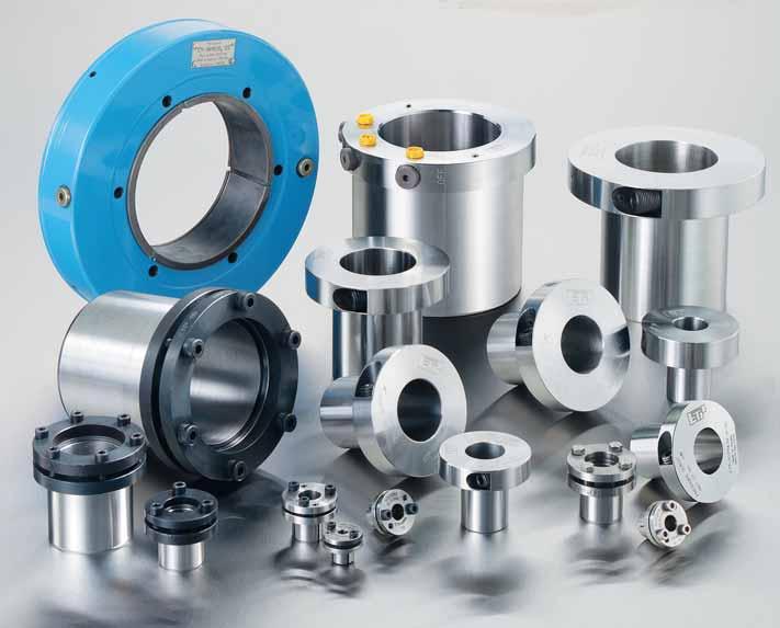
2 The company and the products ETP Transmission AB have developed and manufactured hydraulic hub-shaft connections for more then 30 years, which are sold under the trademark ETP. The company has built up a unique world wide knowledge within the hydraulic fastening and centering field. Continuous development with customers has resulted in a steady flow of new products. Electron beam welding is one of the key manufacturing operations, which gives the ETP-Product range its extreme levels of precision & repeatable performance. The company has built up a leading position within three different business areas: general machine building (described in this brochure), industrial woodworking and metal machining. Since 1995 the company is certified according to ISO Authorized representatives with stock and high levels of technical service are present in each country in Western Europe, North America, Japan, Australia, New Zealand, South-Africa, India and Southeast Asia. Box 1120, SE Linköping, Sweden Tel. +46 (0) , Fax +46 (0) info@etp.se, Internet: 2

3 Pascal discovered the principle We put it to work The scientist Blaise Pascal formulated the principle of pressure propagation in liquids many years ago: A liquid confined in a vessel which is subjected to pressure distributes the pressure uniformly upon the walls of the vessel. ETP has explored the many positive qualities in this principle, developed it further and applied it to the hub-shaft connections. A hydraulic pressure medium confined in a double-walled sleeve is pressurized (with screws/pistons or with an external pump). The pressure is distributed evenly along and around hub/shaft. The double-walled sleeve expands uniformly and gives an even contact pressure against shaft and hub. The ETP-Principle gives because of the hydraulic principle: compact design, fast mounting, easy to position, good runout, does not damage the contact surfaces and is easy to dismantle. These qualities are important today and will be even more important in the future. With increasing requirements on down sizing the machines, better runout/balance, increased machine speeds, shorter downtime for service and increased precision, the ETP hydraulic hub-shaft connections are choosen for more and more designs. 3


4 EASY AND ACCURATE TO POSITION When starting the mounting/pressurizing, the double-walled sleeve will come in contact with the middle of the area on the hub and shaft first. In this situation it is still easy to turn, and axially move the ETP connection, around and along the shaft. The hub is easy to position accurately in the required location and syncronize with other machine elements. At continued pressurizing the double-walled sleeve only moves in the radial direction towards the hub and shaft, the adjusted position will be maintained. This means that time is saved as the mounting will be accurate and correct. SAVES SPACE ALONG THE SHAFT Some of the ETP connections have the pressure screw in the radial direction to the shaft. When the connections are in the radial direction, no space needs to be reserved along the shaft for mounting tools. An advantage with this is, another machine component can be placed all the way up against the flange of the ETP connection. The minimal space needed for the flange makes a very compact design possible. All together this means reduced weight, smaller dimensions and lower polar moment of inertia for the final design. QUICK MOUNTING Mounting of the hydraulic ETP connection is completed and ready within a few minutes. Only a few screws, for some ETP connections only one, need to be tightened to a low tightening torque. The connection can immediately be subjected to a load. Tightening of the screws is not required afterwards. The contact length onto the hub and shaft is long, so that the surface pressure can be kept at a moderate level. The low and even surface pressure means that the hub and shaft surfaces will not be damaged. This means that hubs of aluminium can be used. 4


5 The hydraulic ETP-principle gives advantages at design, manufacturing, mounting, operation and dismantling SMALL BUILT-IN DIMENSIONS The ETP connections require a minimum of space. The double-walled sleeve is thin, the surface pressure is not high and even distributed towards shaft and hub. This makes it possible to minimize the outer diameter of the hub and to use simpler material with a low yield point. The ETP connections leads to reduced total weight and inertia. This makes it possible with quicker start and stops and thus increased productivity. GOOD RUNOUT The hydraulic principle coupled with our accurate machining makes the runout (axial and radial) and balance extremely good. The surface pressure is equal both around and along the shaft and hub. These hydraulic qualities means that the ETP connections give a minimum of vibrations, lower noise level and good precision also at high rpms. By repeated mountings the good runout will be maintained because of the hydraulic working principle. QUICK DISMANTLING Dismantling the ETP connection, is as quick and easy as the mounting. When the screws are loosened, the hydraulic pressure reduces and disappears, the elastically pre-stressed double-walled sleeve returns to its original dimensions and can immediately be removed. The ETP connection can then be mounted as quick again, with the same good precision and performance as the first time. The downtime will be minimized. 5

6 6 QUALITY IN DESIGN AND MANUFACTURE At ETP all are aware about their responsibility for quality. To ensure that our designs meet the customers requirements, we collaborate closely with our sub-contractors and leading customers. When developing new products these are validated together with customers. Production is planned and controlled so that quality and environmental requirements are fully met while maintaining high productivity. Monitoring is systematic and continuous. The quality system complies with the SS-EN ISO


7 Choose the ETP-connection that suits you best ETP-EXPRESS incl. type R/C For fast mounting and compact design. Also in stainless and electroless Nickel coated. Page ETP-TECHNO For extremely good concentricity. For frequent mounting. Page ETP-CLASSIC incl. type R For all normal needs. Also in stainless. Page ETP-MINI incl. type R For small shafts. Also in stainless. Page ETP-HYLOC For fast mounting and high loads. Good concentricity. Page ETP-IMPRESS Shrink joint for hollow shafts. Fast and accurate mounting. ACCESSORIES Torque wrenches, pumps. Connections, screws. Friction increasing methods. TECHNICAL INFORMATION Design aids. Hub, tolerances, runout etc. Design tips. ETP-SPECIAL DESIGNS ETP-OCTOPUS ETP-HYCON ETP-UNIGRIP, ETP-KN etc. Page Page Page Page


8 ETP-EXPRESS has only one screw for pressurising, it is therefore specially designed for when there is a need for the repositioning of the hub to be done fast and accurately. The scew is tightened in the radial direction, this means that no space is used along the shaft for mounting tools. Other components can be mounted on the shaft all the way up to the flange. ETP-EXPRESS has extremely small built-in dimensions which makes a compact design possible. CONSTRUCTION ETP-EXPRESS consists of a double-walled hardened steel sleeve filled with a pressure medium, and a flange. The flange part contains screw and piston with seals to maintain pressure. OPERATION When the pressure screw is tightened the double-walled sleeve expands uniformly against shaft and hub and creates a rigid joint. Dismantling is done by loosening the screw. ETP-EXPRESS returns to its original dimensions and can easily be dismantled. QUALITIES The unique hydraulic principle gives a great number of advantages: Extremely fast mounting/dismantling with only one screw (d > 80 mm, two screws). Radial tightening of the screw saves space along the shaft. Extremely small built-in dimensions. Accurate positioning, no axial movement when mounting. Good concentricity, also after several mountings. 8 When the pressure screw is tightened to the recommended tightening torque, the piston has reached the bottom of the bore. ETP-EXPRESS has created a uniform surface pressure against the shaft and hub.

9 ETP-EXPRESS N N d D D2 L L1 R R ETP- EXPRESS Dimensions TOLERANCES Shaft h7 for d=15 mm. Shaft h8 for d= 5/8", 3/4", 20, 7/8, 25, 1", 1 1/8, 30, 1 1/4", 1 3/8, 35, 1 3/16, 1 1/2", 40, 45, 50, 2", 60, 70, 80, 90, 100 mm. Shaft k6-h7 for d= 19, 22, 24, 28, 32, 38, 42, 48, 55 mm. Hub H7. For further information see under the section for technical information and tolerances. Transmittable axial radial torque force force Screws DIN 915, 12.9 d D D1 D2 L L1 Tr Fr FR R N Tt mm mm mm mm mm mm Nm kn kn Dim. mm mm Nm Notation ETP-EXPRESS XX Polar moment of inertia J kgm , ,1 0,5 M10 15, ,043 0,16 5/8" 15, , ,5 0,5 M10 15, ,047 0, ,5 49, ,3 1 M10 17, ,064 0,20 3/4" 19, ,5 53, ,3 1 M10 17, ,064 0, ,5 53, ,1 1 M ,070 0, ,5 54, ,6 1,2 M10 19, ,097 0,25 7/8" 22, ,5 60, ,6 1,2 M10 19, ,097 0, ,5 60, ,4 M10 20, ,112 0, , ,5 M10 20, ,117 0,27 1" 25, , ,5 M10 21, ,127 0, , ,8 M10 22, ,170 0,34 1 1/8" 28, ,5 69, ,8 M ,180 0, ,5 70, M10 23, ,189 0,35 1 1/4" 31, ,5 71, ,2 M10 24, ,249 0, ,5 77, ,2 M10 24, ,249 0,42 1 3/8" 34, , ,5 M10 26, ,325 0, , ,5 M10 26, ,325 0,48 1 7/16" 36, ,5 85, ,6 M10 27, ,365 0, ,5 86, ,8 M ,761 0,84 1 1/2" 38, ,5 89, ,8 M ,761 0, ,5 89, M ,844 0, , ,2 M16 33, ,971 0, , ,5 M16 34, ,170 1, , M16 36, ,458 1, ,5 103, ,5 M16 37, ,524 1,20 2" 50, ,5 105, ,5 M ,716 1, , M16 40, ,182 1, ,5 132, ,3 M16 43, ,167 1, ,5 153, ,4 M20 50, ,125 3, ,5 162, ,5 M20 56, ,350 3, ,5 171, ,6 2 x M20 61, ,20 4, , ,7 2 x M20 67, ,90 5,90 Tr= Transmittable torque when axial force is 0. Fr= Transmittable axial force when torque is 0. } When the screw is tightened to Tt. The dimensions are valid for ETP-EXPRESS before mounting. FR=Max transmittable radial force at continuous operation. Tt= Recommended tightening torque for the screw/screws. Dimensions subject to alterations without notice. D1 Weight kg TIGHTENING TORQUE When the tightening torque, Tt, is reached the piston is at the end of the bore. Further tightening does not increase the pressure. Runout, balance, number of mountings, hub/hollow shaft, fatigue, temperature and radial loads/bending torque. See the section for technical information. 9


10 The demand from the food and process industries is increasing for stainless steel hub-shaft connections; surface coatings and plating are no longer always sufficient. The most common sizes of ETP-EXPRESS are available in stainless steel as well as plated with a thick layer of electroless Nickel. CONSTRUCTION ETP-EXPRESS type R is made of hardened stainless steel. ETP-EXPRESS C is plated with electroless Nickel, approx. 15 µm, containing also a high proportion of phosphor. The screw for both products is in stainless steel. OPERATION ETP-EXPRESS type R and C work in the same way as ETP-EXPRESS. For type C the following applies: The transmittable torque is reduced because of the lower friction coefficient for Nickel. Cleaning of the contact surfaces must be more carefully done before mounting. If also the shaft or hub is plated with Nickel the transmittable torque will be reduced by 50 %. QUALITIES ETP-EXPRESS type R and C have the same good qualities when it comes to fast and frequent mounting with only one screw in the radial direction, small built-in dimensions etc. as the standard ETP-EXPRESS. All parts exposed to the environment are made of stainless steel (type R) or plated with Nickel (type C). Easy to clean. In food processing this meets essential requirements. The pressure medium and lubricant for the screw are approved for use in the food industry. When the pressure screw is tightened to the recommended tightening torque, the piston has reached the bottom of the bore. ETP-EXPRESS type R and C will have created a uniform surface pressure against the shaft and hub. 10
 Hub H7. For further information see under the section for technical information and tolerances. MATERIAL Type R: Euronorm 1.")
11 ETP-EXPRESS R/C N N d D D2D 2 L1 L R r VV o ETP- EXPRESS Transmittable Dimensions axial radial Screw*) DIN 915, A4 torque force force d D D1 D2 L L1 r Tr Fr FR R N Tt mm mm mm mm mm mm mm v Nm kn kn Dim. mm mm Nm TOLERANCES Shaft h8 (R-15 and C-15 only h7) Hub H7. For further information see under the section for technical information and tolerances. MATERIAL Type R: Euronorm , stainless steel, X19CrNi17-2. Type C: steel, coated with 15 µm electroless Nickel with high proportion of phosphor. For rate of corrosion, see page 31. *)Screw: coated for a low and even friction in the threads. MOUNTING ADVICE Make sure the screw thread is well lubricated (OKS 260 or Molykote D) before each mounting. Runout, balance, number of mountings, hub/hollow shaft, fatigue, temperature and radial loads/bending torque. See the section for technical information. Polar moment of inertia J kgm STAINLESS R , , ,1 0,5 M10 15, ,043 0,16 R-5/8" 15, , , ,5 0,5 M10 15, ,047 0,17 R-3/4" 19, ,5 53, , ,3 1 M10 17, ,064 0,20 R ,5 54, , ,1 1 M ,070 0,21 R-7/8 22, ,5 60, , ,6 1 M10 19, ,097 0,25 R , , ,5 M10 20, ,117 0,27 R-1" 25, , , ,5 M10 21, ,127 0,29 R-1 1/8 28, ,5 70, , ,8 M ,18 0,35 R ,5 71, , M10 23, ,189 0,35 R-1 1/4" 31, ,5 77, , ,2 M10 24, ,249 0,42 R , , ,5 M10 26, ,325 0,48 R-1 1/2" 38, ,5 89, , ,8 M ,761 0,84 R ,5 91, , M ,844 0,88 R , , ,5 M16 34, ,170 1,05 R ,5 105, , ,5 M16 37, ,524 1,20 R-2" 50, ,5 111, , ,5 M ,716 1,28 R ,5 132, , ,3 M16 43, ,167 1,85 R ,5 153, ,4 M20 50, ,125 3,04 R ,5 162, , ,5 M20 56, ,35 3,75 NICKEL COATED C , , ,8 0,5 M10 15, ,043 0,16 C ,5 54, , ,8 1 M ,070 0,21 C , , ,5 M10 20, ,117 0,27 C ,5 71, , M10 23, ,189 0,35 C ,5 91, , M ,844 0,88 C ,5 105, , ,5 M16 37, ,524 1,20 Tr= Transmittable torque when axial force is 0. Fr= Transmittable axial force when torque is 0. } When the screw is tightened to Tt. The dimensions are valid for ETP-EXPRESS R and C before mounting. FR=Max transmittable radial force at continuous operation. Tt= Recommended tightening torque for the screw. Dimensions subject to alterations without notice. D1D 1 Notation ETP-EXPRESS R-XX ETP-EXPRESS C-XX Weight kg 11


12 ETP-TECHNO is specially designed for applications where fast frequent changes or adjustments, with high precision are needed. ETP-TECHNO can be mounted/dismantled 1000 s of times. It is very easy to mount, only one screw, ETP-TECHNO in a tight space, and it also has extremely good concentricity. ETP-TECHNO is the high precision joint among the ETP hub-shaft connections. CONSTRUCTION ETP-TECHNO consists of a double-walled hardened steel sleeve filled with a pressure medium, and a flange. The flange part contains the pressurizing mechanism which consists of a screw and piston with double sealing function, an o-ring and a metallic seal with a steel ball which is pressed against a spherical seating. The outer, D, and inner, d, diameter and the side of the flange towards the hub are accurately machined for extremely good concentricity. The piston and the cylinder are designed for 1000 s of mountings. OPERATION When the pressure screw is tightened the double-walled sleeve expands uniformly against the shaft and the hub thus creating a rigid joint. Dismantling of the joint is done by loosening the screw. ETP-TECHNO returns to its original measurements and can easily be dismantled. QUALITIES The unique hydraulic principle gives a great number of advantages: Fast mounting/dismantling. Only one screw needs to be tightened. Extremely good concentricity, also after several mountings. Can be mounted/dismantled 1000 s of times. Possible to mount in tight spaces. The pressure screw is tightened in the radial direction to the shaft. Small built-in dimensions. The hub can be adjusted easily and accurately. ETP-TECHNO is also suitable as a base for customer adapted solutions. See the section for ETP-Special designs. When the pressure screw is tightened to the recommended tightening torque, Tt, the steel ball seals against the spherical seating. ETP-TECHNO will have created a uniform surface pressure against the shaft and hub. 12

13 ETP-TECHNO N d D L D2D 2 L1 R ETP- TECHNO Dimensions Transmittable axial radial Screws torque force force d mm D mm D1 mm D2 mm L mm L1 mm Tr Nm Fr kn FR kn Dim. R mm N mm Tt Nm TOLERANCES Shaft h8. Hub H7. For further information see under the section for technical information and tolerances. Notation ETP-TECHNO XXX TIGHTENING TORQUE When the tightening torque, Tt, is reached the piston is at the end of the bore. Further tightening does not increase pressure. Runout, balance, number of mountings, hub/hollow shaft, fatigue, temperature and radial loads/bending torque. See the section for technical information. Polar moment of inertia J kgm M ,092 0, M ,153 0, M ,382 0, , M ,382 0, M14 26, ,541 0,69 1 1/4 31, M14 27, ,641 0, M14 27, ,641 0, M ,752 0,84 1 1/2 38, M16 32, ,138 1, M16 33, ,267 1, M16 35, ,503 1, M16 39, ,313 1, M20 46, ,027 2, M ,854 3, M ,600 4, M ,370 4, M22 64, ,062 6, M ,013 8,41 Tr= Transmittable torque when axial force is 0. Fr= Transmittable axial force when torque is 0. } When the screw is tightened to Tt. The dimensions are valid for ETP-TECHNO before mounting. FR=Max transmittable radial force at continuous operation. Tt= Recommended tightening torque for the screw. Dimensions subject to alterations without notice. D1D 1 Weight kg 13


14 ETP-CLASSIC is used in a large variety of applications, for mounting timing belt pulleys, camcurves and arms etc. Positioning along and between the shafts is easy and fast with a high precision. Service and maintenance are also quick because of the easy dismantling. ETP-CLASSIC is recommended for all normal needs. CONSTRUCTION ETP-CLASSIC consists of a double-walled hardened steel sleeve, filled with a specially adopted pressure medium, sealing ring, piston, pressure flange and clamping screws. OPERATION When tightening the screws, the sleeve expands uniformly against hub and shaft and creates a rigid joint. When loosening the screws, the sleeve returns to its original measurements and can easily be dismantled. QUALITIES The unique hydraulic principle gives a great number of advantages: Small built-in dimensions and a reasonable surface pressure means small outside diameter for the hub. Mounting and dismantling is fast. Fine adjustment of the hub can be made during mounting. Low tightening torque and a small number of screws makes the mounting easy. Good concentricity, also after several mountings. ETP-CLASSIC has cap head screws but screws with hex head are available as accessories, see page 24. ETP-CLASSIC in place between the shaft and hub ready for mounting. When the screws have been tightened, ETP-CLASSIC creates an even surface pressure against the hub and shaft along virtually the entire length. 14

15 ETP-CLASSIC D1 D2 d D L1 L2 L Notation ETP-CLASSIC XXX ETP- CLASSIC Dimensions TOLERANCES Shaft h8 k6 (size 15 only h7) Hub H7 For further information see the section for technical information and tolerances. Transmittable torque axial force radial force d D D1 D2 L L1 L2 Tr Fr FR mm mm mm mm mm mm mm Nm kn kn Screws DIN 912, 12.9 Polar moment of inertia J kgm , ,3 2,5 3 M5 6 0,019 0, ,6 5,8 3 M5 8 0,045 0, ,5 6,6 3 M5 8 0,043 0, ,3 8,2 4 M5 8 0,063 0, ,7 9,8 4 M5 8 0,066 0, ,0 10,6 4 M5 8 0,067 0, ,4 13,1 4 M5 8 0,112 0, , ,0 14,7 4 M5 8 0,133 0, , ,3 16,3 4 M5 8 0,180 0, , ,1 18,8 6 M5 8 0,230 0, ,5 21,2 6 M5 8 0,277 0, , ,0 22,8 6 M5 8 0,408 0, , ,8 24,4 6 M5 8 0,414 0, , ,3 26,9 6 M6 13 0,636 0, , ,4 29,3 6 M6 13 0,761 0, , ,0 30,9 6 M6 13 0,943 0, ,9 35,0 8 M6 13 1,301 1, , ,1 8 M6 13 1,959 1, ,1 8 M6 13 2,780 1, ,2 6 M8 32 4,035 2, ,3 6 M8 32 5,500 2, ,0 6 M8 32 8,100 2, ,0 6 M8 32 9,500 3, ,0 8 M ,200 3, ,5 8 M ,100 4, ,0 8 M ,950 4,87 Tr= Transmittable torque when axial force is 0. Fr= Transmittable axial force when torque is 0. } When the screws are tightened to Tt. The dimensions are valid for ETP-CLASSIC before mounting. FR=Max transmittable radial force at continuous operation. Tt= Recommended tightening torque for the screws. Dimension subject to alterations without notice. VERSIONS Also available in a complete range of inch sizes 3/4 4, and in a shorter version for shafts mm, see page 34. Runout, balance, number of mountings, hub/hollow shaft, fatigue, temperature and radial loads/bending torque. See the section for technical information. No. Dim. Tt Nm Weight kg 15


16 The demand from the food and process industries is increasing for stainless steel hub-shaft connections; surface coatings and plating are not always sufficient. The most common sizes of ETP-CLASSIC are also available in stainless steel. CONSTRUCTION ETP-CLASSIC type R is the normal type of ETP-CLASSIC made of stainless steel. Type R has hexhead stainless steel screws, in order to facilitate easy cleaning when used for example in machines for processing food. OPERATION ETP-CLASSIC type R works in the same way as ETP-CLASSIC with a few exceptions: There are a few more screws in type R as the tightening torque is lower for stainless steel screws. The transmittable torque is lower. ETP-CLASSIC type R; in place between the shaft and hub ready for mounting. QUALITIES ETP-CLASSIC type R has the same qualities as ETP-CLASSIC when it comes to fast/backlash free mounting and positioning. All parts exposed to the environment are made of stainless steel. In food processing this meets essential requirements. When the screws have been tightened, ETP-CLASSIC type R will create an even surface pressure against the hub and shaft along virtually the entire length. 16
 DIN 933, A4 Polar moment of inertia J kgm 2 10-3 R-15 15 23 38 28,5 17 30 34 45 6,0 2,5 4 M5 4,5 0,019 0,10 R-20 20 28 45 35 22 37 41 100 10,0 6,6 5 M5 4,5 0,044 0,16 R-25 25 34 49 40 27 43")
17 ETP-CLASSIC R D1 D2 d D L L1 L2 Notation ETP-CLASSIC R-XX ETP- CLASSIC Dimensions torque Transmittable axial force radial force d D D1 D2 L L1 L2 Tr Fr FR mm mm mm mm mm mm mm Nm kn kn Ant. Screws*) DIN 933, A4 Polar moment of inertia J kgm R , ,0 2,5 4 M5 4,5 0,019 0,10 R ,0 6,6 5 M5 4,5 0,044 0,16 R ,8 10,6 7 M5 4,5 0,070 0,21 R , ,3 14,7 7 M5 4,5 0,137 0,30 R , ,5 18,8 9 M5 4,5 0,234 0,41 R , ,5 22,8 9 M5 4,5 0,414 0,58 R , ,8 26,9 9 M6 7,8 0,647 0,74 R , ,0 30,9 9 M6 7,8 0,957 0,92 Tr= Transmittable torque when axial force is 0. Fr= Transmittable axial force when torque is 0. } When the screws are tightened to Tt. The dimensions are valid for ETP-CLASSIC R before mounting. FR=Max transmittable radial force at continuous operation. Tt= Recommended tightening torque for the screws. Dimension subject to alterations without notice. Dim. Tt Nm Weight kg TOLERANCES Shaft h8 (R-15 only h7). Hub H7. For further information see under the section for technical information and tolerances. MATERIAL Euronorm , stainless steel, X5CrNiCuNb16-4. *)Screws: surface coated for a low and even friction in the threads. MOUNTING ADVICE Make sure that the screw threads are well lubricated (OKS 260 or Molykote D) before each mounting. Runout, balance, number of mountings, hub/hollow shaft, fatigue, temperature and radial loads/bending torque. See the section for technical information. 17

 and clamping screws (type R stainless).")

18 ETP-MINI is far superior to keyways or setscrews because it allows an adjustable, backlash free joint. Typical applications are mounting of hubs on small electrical motors, stepmotors and encoders. As no keyways are needed, the shaft will not be weakened and the unbalance will be lower, which is very important at high speeds, as the motor bearings are sensitive to vibrations. Also available in stainless, ETP-MINI type R, suitable for the food processing industry etc. CONSTRUCTION ETP-MINI consists of two, partly slotted, conical steel sleeves (type R stainless) and clamping screws (type R stainless). OPERATION By tightening the screws, the inner sleeve is pressed against the shaft and the outer sleeve against the hub, thus forming a rigid joint. When dismantling, one or if necessary, two of the screws are moved to the threaded dismantling holes in the flange. By tightening, the sleeves will separate and the joint will loosen. ETP-MINI type R has one screw more than the normal ETP- MINI in order to transmit the same torque (lower tightening torque for stainless screws). The built-in dimensions are the same. QUALITIES Easy to mount. Good runout. Allows wide tolerances. Available in stainless steel (type R). ETP-MINI R has stainless cap head screws but stainless hex head screws are available as accessories, see page 24. The inner sleeve, for ETP-MINI incl. type R, has a light recess close to the flange in order to create a more uniform surface pressure to the shaft. 18

19 ETP-MINI inkl. typ R D1 D2 d D L2 L1 L ETP- MINI ETP- MINI Dimensions Dimensions Transmittable torque or axial force Transmittable torque or axial force Screws DIN 912, 12.9 d D D1 D2 L L1 L2 Tr Fr Tt mm mm mm mm mm mm mm Nm kn Ant. Dim. Nm Screws *) DIN 912, A4 d D D1 D2 L L1 L2 Tr Fr Tt mm mm mm mm mm mm mm Nm kn Ant. Dim. Nm Notation ETP-MINI XX Polar moment of inertia J kgm ,5 2 M3 2 2,1 0,03 1/4 6, ,5 2 M3 2 2,1 0, ,5 25, M4 4 3,3 0, ,5 2 M4 4 4,4 0,05 3/8 9, ,5 2 M4 4 4,4 0, ,5 2 M4 4 4,3 0, ,5 29,5 36 6,5 2 M4 4 6,2 0, ,5 29,5 40 6,5 2 M4 4 6,1 0,06 1/2 12, ,5 29,5 42 6,5 2 M4 4 6,0 0, ,5 31,5 66 9,5 3 M4 4 13,2 0,08 Tr= Transmittable torque when axial force is 0. Fr= Transmittable axial force when torque is 0. } When the screws are tightened to Tt. The dimensions are valid for ETP-MINI before mounting. Tt= Recommended tightening torque for the screws. Dimensions subject to alternations without notice. Notation ETP-MINI R-XX Polar moment of inertia J kgm R ,7 3 M3 1,2 2,1 0,03 R ,5 25,5 17 4,4 3 M4 2,7 3,3 0,04 R ,4 3 M4 2,7 4,4 0,05 R ,4 3 M4 2,7 4,3 0,05 R ,5 29,5 25 4,4 3 M4 2,7 6,2 0,06 R ,5 29,5 27 4,4 3 M4 2,7 6,1 0,06 R ,5 31,5 48 6,5 4 M4 2,7 13,2 0,08 Tr= Transmittable torque when axial force is 0. Fr= Transmittable axial force when torque is 0. } When the screws are tightened to Tt. The dimensions are valid for ETP-MINI R before mounting. Tt= Recommended tightening torque for the screws. Dimensions subject to alternations without notice. Weight kg Weight kg TOLERANCES Shaft: k6-h10. Hub: H8. For further information see under the section for technical information and tolerances. MATERIAL FOR TYPE R Euronorm , stainless steel, X10CrNiS18-9. *)Screws: surface coated for a low and even friction in the threads. MOUNTING ADVICE Make sure the screw threads for type R are well lubricated (OKS 260 or Molykote D) before each mounting. Runout, balance, number of mountings and hub/hollow shaft. See the section for technical information. 19

 in the radial direction and the same in the axial. This makes it possible to choose radial or axial connection of the hoses.")

20 ETP-HYLOC, due to its robust design, is ideally suited to work in difficult environments and heavy operations like steel rolling mills, process industry etc. An interesting application, among many, has been fastening of rolls to shafts. ETP-HYLOC is fast to mount, has good concentricity and can take high radial loads. CONSTRUCTION ETP-HYLOC is a hydromechanical joint, which consists of a double-walled steel sleeve which encloses a conical moveable piston. In the flange there are three threaded connections ( ON, P and OFF ) in the radial direction and the same in the axial. This makes it possible to choose radial or axial connection of the hoses. Mounting and dismantling is carried out with a hydraulic pump. OPERATION When the piston is moved, by the hydraulic pressure from the pump, the double-walled sleeve expands uniformly against shaft and hub to form a rigid joint. When dismantling, the piston is moved in the opposite direction and the joint will loosen. A small amount of oil will be taken via spiral tracks in the piston between the surfaces (pressure applied through the P connection), in this way making it easier for the piston to move. QUALITIES High transmittable torque which can be varied by changing the mounting pressure. Fast mounting/dismantling in tight spaces. By using a pump the time is reduced to a minimum even for large sizes. Radial and axial connection is possible. Fine adjustments of the hub can be made when mounting. Good concentricity, also after several mountings. High radial load capacity. Mounting: Apply pressure in the ON and P (not shown) connections. When mounted no hydraulic pressure remains. The small conical angle prevents the piston from releasing. Dismantling: Apply pressure in the OFF and P (not shown) connections. ETP-HYLOC returns to its original measurements and the joint is loose. 20

21 ETP-HYLOC 7 7 OFF P ON D1 d D 2xH 2xH L1 L ETP-HYLOC is prepared for axial connection of the hoses (where the plastic plugs are situated). If radial connection is to be made, the steel plugs are moved to the axial connections and are tightened with a torque wrench to 20 Nm. Axial/radial connections G 1/8. Notation: ETP-HYLOC XXX ETP- HYLOC Dimensions Transmittable torque or axial force at 1000 bar Shaft h7 Shaft h8 Min. hub DH mm d D D1 L L1 Tr Fr Tr Fr Vieldpoint N/mm 2 mm mm mm mm mm knm kn knm kn >300 >400 Tr= Transmittable torque when axial force is 0. Fr= Transmittable axial force when torque is 0. DH=Outer diameter for hub material in steel. H Polar moment of inertia J kgm ,6 70 2, M8 3,2 2, , , M8 5,4 3, , , M8 8,7 4, , , M8 14 5, , , M , , , M , , , M , , M , , M , , M , , M M M M M Weight kg H: Threads for easy handling. Dimension subject to alterations without notice. ETP- HYLOC 600 bar 800 bar 1200 bar Shaft Min. hub DH Shaft Min. hub DH Shaft Min. hub DH h7 h8 Yieldpoint h7 h8 Vieldpoint h7 h8 Yieldpoint Tr Tr N/mm 2 Tr Tr N/mm 2 Tr Tr N/mm 2 knm knm >200 >300 >400 knm knm >300 >400 knm knm > ,8 0, ,6 1, ,3 3, ,1 1, , ,9 5, ,4 2, ,8 5, ,9 9, ,6 5, , ,3 14, ,3 7, ,7 11, ,6 20, , ,2 17, ,3 29, ,8 15, ,8 23, , ,3 20, ,7 31, , ,2 24, ,5 38, , ,6 32, ,3 49, ,6 82, ,5 41, , ,8 51, , Transmittable torque at different mounting pressures. The torque for sizes 80 can be increased by using ETP-HFC, see page 26. Runout, balance, number of mountings and radial loads/bending torque. See the section for technical information. TOLERANCES Shaft h7 or h8. Hub H7. For further information see under the section for technical information and tolerances. MOUNTING ADVICE The contact surfaces L and L1 must be completely covered by the shaft and hub. The oil for the pump should be a transmission oil type 80 W. For pumps/connections see page 25. For other hub materials, for example aluminium, contact us. MOUNTING PRESSURE The mounting pressure is normally 1000 bar. Max mounting pressure 1200 bar. Dismantling requires max. 200 bar higher pressure than for mounting. VERSIONS Larger sizes available, see page 34. ETP-HYLOC can be designed to suit special applications on request. 21


22 The connection of a hollow shaft, for example from a hydraulic motor or a gearbox, to a shaft is today often done with a mechanical shrink disc. These are built up of conical rings. When mounting a high radial force is needed to compress both the conical rings and the hollow shaft. This is achieved through a lot of screws with a high tightening torque. Mounting/dismantling causes long downtime which is expensive in the process industry for example in the pulp and paper industry. ETP IMPRESS is a shrink connection where the mounting and dismantling is done easily and quickly through hydraulic pressure. CONSTRUCTION ETP-IMPRESS consists of two flange parts and an inner sleeve with two or more conical surfaces, connections for hydraulic are both radial (RC) and axial (AC), locking screws (LS), dismantling screws (DS) and seals. OPERATION The sealed chamber between the flanges is pressurised with a hydraulic pump. The pressure makes the flanges move apart in the axial direction, the conical surfaces will then press the inner sleeve uniformly against the hollow shaft. The hollow shaft will be compressed and engage the solid shaft. A surface pressure will be built up between the hollow shaft and the solid shaft. When the mounting pressure is reached the axial locking screws are tightened. The hydraulic pressure is released; the flanges will stay in position supported by the locking screws. The connection is ready. When dismantling, the joint is pressurized; the locking screws loosened, the pressure released and the connection is free. Because of the friction resistance around the seals it may be necessary to use the radial dismantling screws for loosening ETP-IMPRESS from the hollow shaft. QUALITIES The unique hydraulic principle gives a great number of advantages. 22 Mounting/dismantling is done quickly, easily and accurately. Can be mounted/dismantled a great number of times without servicing. Can be mounted in tight spaces. Is possible to dismantle without hydraulic. Approx. same built-in dimensions as mechanical joints. Direct relation between hydraulic pressure and transmittable torque. No large screws with high tightening torque for mounting, which have a high-risk breaking. DS RC AC LS Mounting is done in a couple of minutes with hydraulic, even on large hollow shafts. Dismantling is as quick.

23 ETP-IMPRESS D 0.5x B 0.5x B B b R da d ds L ETP- IMPRESS Dimensions Transmittable torque or axial force Max. width Mounting pressure Locking screws DIN 913, HRC 45 Axial connection d da D L B Tr Fr B+ B bar No. Dim. ds R Dim. b mm mm mm mm mm Nm kn mm mm mm mm Notation ETP-IMPRESS XXX Dismantling screws, 4 pcs , M M4 7,3 0, ,6 6 M M6 10,6 0, ,5 7 M M6 13,2 0, ,5 10 M ,5 M10 15,1 0, ,9 11 M M10 16,6 0, ,8 9 M ,5 M10 18,4 0, , M M10 19,9 0, Tr= Transmittable torque when axial force is 0. Fr= Transmittable axial force when torque is 0. } At the mounting pressure acc. to above. Dimensions subject to alteration without notice. Max. oil volume l Weight kg TOLERANCES da (mm) Solid shaft Tolerances, da Hollow shaft inside (mm) h6 +0,004 till +0, h6 +0,004 till +0, h6 +0,004 till +0, g7 H8 Outer diameter hollow shaft, d = h8. MOUNTING Mounting pressure acc. to above. Same for dismantling. All types of hydraulic oil can be used. Clean the contact surfaces between hollow/solid shaft thoroughly. MAX. STROKE, B B can be reached by largest possible play within the prescribed tolerances. BUILT-IN The contact area L must be covered by both the hollow shaft and the solid shaft mounted in the hollow shaft, before pressurizing. CONNECTIONS Axial and radial pump connections, G 1/8, 180 apart. LOCKING SCREWS The locking screws are tightened to approx. 5 Nm, before the pressure is released. All the screws should be tightened equally. HYDRAULIC PUMPS See the accessories section. Max. oil volume acc. to above refers to max. stroke, B. LOADS Torque and axial forces are calculated for a hollow shaft of nodular iron (E= MPa). Friction Coefficient, µ, between solid shaft and hollow shaft of 0,15 (well cleaned surfaces). 0,8 (200 or 280 bar) 1 (250 or 350 bar) If the hardness of the hollow shaft is < 250 HB, the surface might be damaged. This can be avoided by reducing the mounting pressure. The transmittable torque will then be proportionally reduced. For example a hardness of 150 HB, a reduction of the mounting pressure by 20% is recommended. 23


24 ETP-EXPRESS incl. type R and C ETP-TECHNO SCREWS All pressure screws for ETP-TECHNO and ETP-EXPRESS incl. type R and C have cap heads. These are available as spare parts. TORQUE WRENCHES The torque wrenches are designed for ETP-TECHNO and ETP-EXPRESS incl. type R and C. They are equipped with wratch head and snap function when the fixed torque (recommended tightening torque, Tt) is reached. The hex head key is integrated in a specially designed adapter which facilitates handling and accessibility. The torque wrenches are specially designed to facilitate the use of the ETP connections and assure a correct tightening. For size ETP-EXPRESS Torque wrench Torque (Nm) M M M39 39 Torque wrenches for ETP-EXPRESS incl. type R and C. For size ETP-TECHNO Torque wrench Torque (Nm) M M M M M M80 80 Torque wrenches for ETP-TECHNO. ETP-CLASSIC incl. type R ETP-MINI inkl. type R HEX HEAD SCREWS For ETP-CLASSIC and ETP-MINI R there are hex head screws as accessories. These can be used when space in the axial direction is limited. ETP-CLASSIC hex head screws, DIN ETP-MINI R hex head screws, DIN 933 A4 (surface coated). TORQUE WRENCHES The torque wrenches have been designed for ETP-CLASSIC and ETP-MINI incl. the R types. They have a fixed torque which releases with a snap at the recommended tightening torque, Tt. The torque wrench makes the mounting easier and guarantees a correct tightening. It is equipped with an adapter which fits the corresponding screws for the ETP connection. For ETP-CLASSIC and ETP-MINI R there is an adapter for hex head screws as an accessory, in case the screws have been changed. For size ETP-CLASSIC Torque wrench Torque (Nm) Adapter for hex head 15 M06 6 A M08 8 A M13 13 A M32 32 A13 R-15 R-40 MR4,5 4,5 Standard R-45 R-50 MR7,8 7,8 Standard Torque wrenches for ETP-CLASSIC incl. type R. To facilitate the use of the ETP hub-shaft connections there are specially designed torque wrenches, hex head screws and adapters for these. For size ETP-MINI Torque wrench Torque (Nm) Adapter for hex head 6 1/4 M M04 4 R-6 MR1,2 1,2 M-R6* R-8 R-14 MR2,7 2,7 A07 Torque wrenches for ETP-MINI incl. type R. *Complete wrench. 24


 and one nipple (N), for example type 02 of C-02 and N-02.")


25 Accessories ETP-HYLOC C-02 N-02 C-03 N-03 Quick connection Quick connection type 02. type 03. QUICK CONNECTIONS When ETP-HYLOC needs to be mounted frequently and fast, the hoses can be equipped, as accessories, with special highpressure quick release chucks. The ON, P, and OFF connections for ETP-HYLOC are then equipped with the corresponding nipples. There are the following 2 versions: Type 02: the chuck, C-02, is screwed onto the nipple, N-02, with an outer ring. Typ 03: the chuck, C-03 is pressed on to the nipple, N-03. This type has bigger built-in dimensions and can not be used axially, if the shaft pass all the way through, for sizes 110 mm. 3 nipples are needed for each ETP-HYLOC and for each pump 3 chucks. A quick connection consists of one chuck (C) and one nipple (N), for example type 02 of C-02 and N-02. Handpump H-11 is delivered in a practical steel box. HYDRAULIC PUMPS The pumps are designed for ease of use at the pressures and volumes that are needed for ETP-HYLOC. The handpump H-11 is a robust, CE marked, pump. Motorpump A-03 is designed to be used when mounting frequently. Both pumps are equipped with manometer and 3 hoses (length 3 m), 2 high-pressure hoses and a thinner hose for the return oil. A threaded connection G 1/8 is on each hose which is suitable for ETP-HYLOC. Max. pressure bar, controlled by a pressure release valve. The pressure release valve is available as accessory for 700 and 1000 bar for the handpump H-11. Motorpump A-03, pneumatical driven. ETP-IMPRESS HYDRAULIC PUMP The pump capacity and handling is designed for the oil volumes and pressures needed for all sizes of ETP-IMPRESS (100 to 260 mm). It is delivered with manometer and hose (length 2 m), hose connection G 1/8. Max. pressure 400 bar. Oil volume for the pump 1 litre. Equipped with an overflow connection for larger return flows. Handpump H30. 25


26 Friction increasing methods In certain applications high even loads or high peak loads occur, which would cause the ETP hub-shaft connection to slip. To overcome this problem some ETP accessories have been developed which increases the coefficient of friction, µ, and therefore the transmittable torque and axial force. The enlarged drawings below illustrate the various products. The bore surface of the ETP hub-shaft connection is shown in blue, the shaft in grey. Steel ETP-FRICTION ETP-FRICTION is a liquid containing extremely small, hard, irregular particles which "grips into" the contact surfaces. It is easily applied with a brush or cloth. ETP-FRICTION will not harden or cure. Content in the can: 125 ml. ETP-INTERFIX ETP-INTERFIX is a specially developed anaerobic adhesive which fills the irregularities in the surfaces. When hardened ETP-INTERFIX forms a layer of approx. 0,002 mm. Content in the bottle: 10 gram. Some premachining of the inner- and outer diameter of the ETP hub-shaft connection is necessary to make sure that dismantling is possible. Instruction is included. ETP-HFC ETP-HFC (High Friction Coating) is a surface treatment of the bore and outside diameter of the ETP hub-shaft connection. ETP-HFC is a carbide coating of small, sharp particles which are imbedded into the treated surface. Is offered separately. TRANSMITTABLE TORQUE CAPACITY Untreated ETP hub-shaft connection = 1 M. Torque duty ETP-FRICTION ETP-INTERFIX ETP-HFC Static 2 M 2-3 M 2 M *Pulsating Not suitable 2-3 M 2 M *Alternating Not suitable 2-3 M 2 M *For applications with a large number of load cycles (more than times) at an increased torque level, there is a risk of fatigue in the ETP product. Please contact us to confirm your application. The friction increasing methods allows for easy dismantling of the ETP hub-shaft connections. ETP-FRICTION and ETP-INTERFIX must be reapplied after remounting. The methods only work for locking assemblies with unslotted sleeves. They have only been tested on ETP hub-shaft connections. 26

27 Technical information Information on On the homepage there is updated information about the products, new products, mounting instructions and links to most of the ETP representatives. CAD SYMBOLS To facilitate the design work there are CAD symbols in the form of side and front views and 3D-views for most of the ETP connections ready to be down loaded. Transmittable torque L s Built-in principle of ETP-connection. D H The ETP connections are tubular and create a surface pressure on the shaft and the hub. By the friction resistance both axial forces and torques can be transmitted. The amount will be determined by the area of the contact surface, the surface pressure and the coefficient of friction (µ). The following formula is valid: T r = p s πd 2 L s µ 2 L s = the contact length. p s = surface pressure on the shaft. p H = surface pressure on the hub. Axial force F1 Fr If axial force (F 1 ) and torque (T 1 ) are to be transmitted at the same time, the following formula is valid. 2 2 F 1 T this means that the value should be F r T r inside the quarter circle in the diagram. () ( ) Fr and Tr are the rated values for axial force and torque for the different ETP products. T1 Tr 27
28 Coefficient of friction (µ) Recommended surface finish, shaft/hub Ra max 3,0 (µm) Ra min 1,0 (µm) The coefficient of friction depend on a number of factors. The most important are: SURFACE FINISH The surface must not be too smooth. If it is, the influence of impurities can be great. A good turning operation is often better than grinding. CLEANLINESS It is very important that the surfaces are well cleaned. Grease on the surfaces will drastically reduce the coefficient of friction. A thin oil will however only reduce the coefficient of friction with about 0,03 µ. MATERIAL The coefficient of friction varies depending on the materials of the contact surfaces, see table. Value of µ for well cleaned contact surfaces steel stainless steel steel cast iron aluminium aluminium bronze stainless steel stainless steel 0,15 0,13 0,17 0,20 0,15 0,15 Surface pressure and torque Max. tightening torque (screw quality 12.9) *M4 **M5 **M6 **M8 5 Nm 10 Nm 17 Nm 40 Nm If the tightening torque is increased the transmittable torque will increase. *) Valid for ETP-MINI. Transmittable torque, Tr, is increased by 20 %. **) Valid for ETP-CLASSIC. Transmittable forque, Tr, is increased by 25 %. This effect can only be used if the operating temperature < the mounting temperature. If the surface pressure is too low, a metallic contact between the surfaces will not be created because of oxide layers. If the surface pressure is too high, plastic deformation can occur and the friction will decrease dramatically. The hydraulic ETP principle gives a surface pressure within the right range, which is also utmost even around and along the contact area. The surface pressure from the ETP connections (not ETP- HYLOC or ETP-IMPRESS) is at the recommended tightening torque: p s = approx. 90 N/mm 2. p H = approx. 70 N/mm 2. By increasing the surface pressure the transmittable torque can be increased, see table. Tolerances Change of torque when ETP-CLASSIC is mounted on: h9 shaft h8 shaft k6 shaft - 25 % acc. to techn. data + 20 % Recommended tolerances for shaft and hub are given under the section for each product. If the tolerance differs from these so the play between the contact surfaces is increased. The surface pressure and the torque will decrease. The opposite is valid for decreased play. See example in the table. Shaft tolerances in µm (upper/lower limits) Hub tolerances in µm (upper/lower limits) Shaft dia. k6 h7 h8 h9 h10 Shaft dia. H7 H8 (3) 6 +9/+1 0/-12 0/-18 0/-30 0/-48 (10) /0 +27/0 (6) /+1 0/-15 0/-22 0/-36 0/-58 (18) /0 +33/0 (10) /+1 0/-18 0/-27 0/-43 0/-70 (30) /0 +39/0 (18) /+2 0/-21 0/-33 0/-52 0/-84 (50) /0 +46/0 (30) /+2 0/-25 0/-39 0/-62 0/-100 (80) /0 +54/0 (50) /+2 0/-30 0/-46 0/-74 0/-120 (120) /0 +63/0 (80) /+3 0/-35 0/-54 0/-87 0/-140 (180) /0 +72/0 (120) /+3 0/-40 0/-63 0/-100 0/-160 (250) /0 +81/0 (180) /+4 0/-46 0/-72 0/-115 0/
29 Technical information Dimensioning of hub and hollow shaft For ETP-HYLOC and ETP-IMPRESS see information under the corresponding product section, the information below is not valid for these. Because of the even and reasonable surface pressure and the compact built-in dimensions of the ETP connections, a thin material in hub and shaft can be used. Also aluminium can be used. For hubs and hollow shafts in steel, the yield point of those decides the thickness of the material. For cast iron and aluminium the module of elasticity is decisive. The requisite thickness can be selected from the table or more accurately in the diagram. HUB Material D N /D Steel incl. stainless, ReL>300 N/mm 2 1,4 Steel incl. stainless, ReL>220 N/mm 2 1,5 Cast iron, E=120 kn/mm 2 2,0 Aluminium, E=70 kn/mm 2 2,5 ReL = Yield point for the material. E = Module of elasticity. D H = The minimum outer diameter of the hub. d i = The maximum inner diameter of the hollow shaft. o = Effective stress. For other notations see figure on page 27. If D H /D < 1,4 for the hub or if d i /d > 0,6 for the hollow shaft, contact us for advice. For all materials there will be an elastic expansion/ compression of the hub/hollow shaft. The expansion/compression will not be uniform of the hub/ hollow shaft if the material is unsymmetrical. For accurate calculation contact us. HOLLOW SHAFT Material d i /d Steel incl. stainless, ReL>300 N/mm 2 0,6 Steel incl. stainless, ReL>240 N/mm 2 0,5 Cast iron, E=120 kn/mm 2 0,3 Aluminium, E=70 kn/mm 2 0,2 o (N/mm 2 ) o (N/mm 2 ) ,0 1,2 1,4 1,6 1,8 2,0 2,2 2,4 D H /D 100 0,1 0,3 0,5 0,7 d i /d Runout and balance The hydraulic ETP principle assures a good runout and balance. All products are balanced by design. For guide values see the table. To these values the runout/unbalance for shaft and hub in the actual case has to be added in order to get the final value when mounted. Dynamic balancing can be done on request. ETP-EXPRESS and ETP-TECHNO can be dynamically balanced to G 2,5 on request. ETP-EXPRESS ETP-TECHNO ETP-CLASSIC ETP-MINI ETP-HYLOC incl. type R and C incl. type R incl. type R Runout (mm)* < 0,02 0,006 0,03 0,06 0,02 0,01 0,02 Unbalance (gmm/kg) ** * Values are also valid after repeated mountings. ** For size 100 mm, with radial mounted steel plugs, the unbalance is larger. 29
30 Number of mountings ETP connection Nbr. of mountings ETP-EXPRESS ETP-EXPRESS ETP-EXPRESS ETP-EXPRESS R and C ETP-EXPRESS R and C ETP-EXPRESS R ETP-TECHNO ETP-TECHNO ETP-TECHNO ETP-CLASSIC 100 ETP-CLASSIC R 50 ETP-MINI 100 ETP-MINI R 50 ETP-HYLOC 2000 ETP-IMPRESS 200 One of the qualities with the ETP connections are their ability to be mounted quickly and repeatedly with maintained performance and precision. There is however a limit when the screw/screws will be worn and has to be changed. If the threads are cleaned and regularly lubricated, the guide values in the table can be used. The values indicates when the screws needs to be changed, the ETP connection lasts longer. For the R and C types it is very important that the screws are well lubricated when tightening, both for proper function and full lifetime capabilities. When used in food processing applications or similar we recommend the lubricants OKS 260 or Molykote D. For other applications Molykote G-n plus can be used. The value for ETP-IMPRESS indicates when it needs to be dismantled for lubrication of the tapered surfaces. We recommend Molykote G-Rapid plus. ETP-HYLOC is not recommended for more mountings than acc. to the table. Fatigue ETP connection Alternating Pulsating ETP-EXPRESS incl. typ R and C 0,5 0,6 ETP-TECHNO 0,7 0,8 ETP-CLASSIC incl. type R: mm 0,6 0,7 ETP-CLASSIC incl. type R: mm 0,5 0,6 When the loads are in form of alternating or pulsating torque it is recommended to reduce the transmittable torque, Tr, with the factors according to the table (factor Tr). The values are based on tests and calculations on the lifetime of ETP connections. The lifetime for the ETP connection increases if the play between the contact surfaces is decreased, for example ETP- CLASSIC can be used on a shaft tolerance of k6, instead of the recommended h8. ETP-MINI and ETP-HYLOC can take essentially higher fatigue loads. The fatigue loads do not affect ETP-IMPRESS as they go through the hollow shaft. Radial loads and bending torque kn ETP-CLASSIC incl. type R ETP-TECHNO Most friction joints have limited capacity to transmit radial forces and bending torque. High levels of these loads can affect the function of the ETP connection. The values acc. to the diagram and table based on tests can serve as guide lines. ETP-MINI and ETP-HYLOC can transmit essentially higher radial forces than the other connections ETP-EXPRESS incl. type R and C Radial force shaft size. mm ETP-EXPRESS ETP-TECHNO ETP-CLASSIC ETP-MINI ETP-HYLOC incl. type R and C incl. type R incl. type R Bending torque as % of transmittable torque, 30
31 Technical information Temperature t ( C) T ( C) ,4 0,6 0,8 1,0 1,2 1,4 1,6 1,8 ETP-TECHNO ETP-EXPRESS incl. type R and C ETP-CLASSIC incl. type R M Tk T Tr M The pressure medium in the hydraulic ETP connections and the double-walled steel sleeve have different volume expansion coefficients. This means that when the temperature rises, the pressure in the connection increases and a higher torque can be transmitted. The opposite is valid at decreasing temperature. Also the seals built into the connections decides the upper and lower operating temperature. The following has to be taken into consideration when the operating temperature differs from the mounting temperature: Max. and min. temperature for continuos operation, see table. ETP-MINI and ETP-HYLOC can withstand essentially wider upper and lower limits. The decreases in torque due to lower operating temperatures. See diagram. ETP-MINI, ETP-HYLOC and ETP-IMPRESS are not affected. T r = transmittable torque acc. to technical data. T k = transmittable torque at operating temperature. ETP connection Min. temp. C Max. temp. C ETP-EXPRESS incl. type R and C ETP-TECHNO ETP-CLASSIC incl. type R ETP-IMPRESS Keyways If there is a keyway in the shaft or hub, we recommend it to be filled in with for example some two component hardening medium (not for ETP-MINI or ETP-IMPRESS). The medium is then hand grind to the diameter of the shaft/hub. This prevents deformation and dismantling problems of the double-walled sleeve. Rate of corrosion Electroless Nickel gives an extremely good protection against all types of water, strong caustic solutions,strong and weak acids, organic acids and all types of salt solutions. It is used successfully in most industries i.e. food and drug-, automotive-, process-, chemical-, and printing industries. Solution µm/year 26% NaCI 0,2 25% KCI 0 31% Na 2 SO 4 0,8 27% AI 2 (SO 4 ) % CH 3 CO 2 H 25 5% C 6 H 8 O % (CO 2 H 2 3 2% NH 3 * 28 28% NH 3 * 16 27% NH 4 CI 8 43% (NH 4 ) 2 SO 4 3 H 2 O 0,1 80% H 3 PO 4 3 1% FeCI Guide values for the corrosion speed in mm/year of electroless Nickel. Solution µm/year 10% acetic acid 25 Glacial acid 0,8 5% citric acid 2 10% oxalic acid* 3 Formic acid 13 Borax 10 Vinegar 10 Chlorine-wet 10 Sodium Bicarbonate 10 Beer 2 Milk* 2 Fruit and lemon juice 2 Oil vegetable 2 Sodium Hydroxide 2 * Will turn black 31
32 rpm ETP-TECHNO Max spel, tol. D N H /D=1.4 ETP-TECHNO Min spel, tol. D N H /D=1.4 ETP-TECHNO Max spel, tol. D N H /D=2 Due to centrifugal force, the transmittable torque will be reduced with increasing speed (rpm). The diagram gives examples for ETP-TECHNO 50 with a steel hub. A reduced tolerance between the contact surfaces gives a higher surface pressure at the same tightening torque, and thus higher transmittable torque at high speeds. A thicker hub is more effected by the centrifugal force and the torque will reduce faster at increasing speed. The example is not directly applicable for other sizes or types of ETP connections. Contact us for assistance with calculations at high speeds. In humid environments, at varying temperature and with a hub made from aluminium ETP-CLASSIC type R can be used. Thanks to the flexibility of ETP-CLASSIC R at varied temperatures, it can be used in hubs of aluminium. Because of the even surface pressure and the lack of slotted sleeves, ETP-CLASSIC R can function as a sealing element up to a pressure difference, p1 p2, of 50 bar. 0 When manufacturing precision gears, they can be fastened with ETP- EXPRESS. If the gear is fixed in its position with an axial screw or pin before the last grinding operation, a repeatability within 2 µm will be achieved. ETP-TECHNO gives advantages when used to fasten printing cylinders in light materials for example aluminium. The cylinder can be changed 1000's of times, using the same ETP-TECHNO, with maintained good concentricity and repeatability. The radial access to the screw facilitates the handling and saves space. 32
33 Technical information Design tips There is a linear ratio, between the transmittable torque and the tightening torque for the screw, for ETP-EXPRESS and ETP-TECHNO. The torque can be roughly selected for when the connection slips, by proper choice of hub/shaft tolerances and tightening torque. The connection can then be used as an overload protection with limited slipping. Long thin rollers subjected to high bending torque, can be fastened to stub shafts with ETP-HYLOC. To decrease the elastic deformation of the roller and make it easier to take up the bending torque, the inner part of the hub and the stub shaft can be designed with conical support surfaces. ETP-HYLOC gives good concentricity and fast changes. ETP-HYCON S is a hydro-mechanical shaft-shaft coupling for high torque and rigidity. The mounting is done, as for ETP-HYLOC, with an external pump. The design is type approved by for example DNV for use in the drive line for ships. Other important applications are in the steel-, paperand other heavy industry, where the requirements are for high torque, low weight, high rigidity and short down time. Separate brochure is available. ETP-OCTOPUS is a connection where the pressure setting is done with an external pressure source. Suitable applications are when repositioning of parts are to be done frequently, fast and precise. Several connections can be clamped/loosened simultaneously. Separate brochure is available. 33
34 ETP-CLASSIC type S ETP- CLASSIC Dimensions d D D1 L L1 L2 mm mm mm mm mm mm Transmittable torque or axial force Tr Nm Notation ETP-CLASSIC S-XX Fr kn No. Screws DIN 912, 12.9 Dim. Tt Nm Weight kg S M5 8 0,15 S M5 8 0,14 S M5 8 0,17 S M5 8 0,24 S M5 8 0,32 S M5 8 0,46 S M6 13 0,57 S M6 13 0,72 ETP-CLASSIC also has limited availability in a shorter version, type S, which is especially suitable for small hubs. The main dimensions are given in the table, for notations please refer to technical data for ETP-CLASSIC. TOLERANCES Shaft: h9 (for size 19: k6 h8). Hub: H7. ETP-CLASSIC in inch ETP- CLASSIC Dimensions d D D1 L L1 L2 tum mm mm mm mm mm Notation ETP-CLASSIC XXX Transmittable torque or axial force Tr Nm Fr kn No. Screws DIN 912, /4" 3/4" ,3 3 M5 8 7/8" 7/8" ,1 4 M5 8 15/16" 15/16" ,7 4 M5 8 1" 1" ,2 4 M /8" 1 1/8" ,5 4 M /16" 1 3/16" ,5 4 M /4" 1 1/4" ,1 4 M /16" 1 5/16" ,5 4 M /8" 1 3/8" ,1 6 M /16" 1 7/16" ,8 6 M /2" 1 1/2" ,7 6 M /8" 1 5/8" ,2 6 M /16" 1 11/16" ,7 6 M /4" 1 3/4" ,0 6 M /16" 1 15/16" ,9 6 M6 13 2" 2" ,3 6 M /16" 2 3/16" ,6 8 M /16" 2 7/16" ,5 8 M /2" 2 1/2" ,6 6 M /16" 2 15/16" ,0 6 M8 32 3" 3" ,1 6 M /16" 3 7/16" ,0 7 M /16" 3 15/16" ,0 8 M8 32 4" 4" ,0 8 M8 32 Dim. Tt Nm ETP-CLASSIC is also available in a large assortment of inch sizes. The main dimensions are given in the table, for notations please refer to technical data for ETP-CLASSIC. TOLERANCES ETP-CLASSIC Shaft tolerance 3/4 0 till 0,0015 7/8 1 1/2 0 till 0, /8 2 15/16 0 till 0, /16 0 till 0, / till 0,0030 ETP-CLASSIC Hub tolerance 3/4 1 15/16 0 till +0, /16 0 till +0, /2 4 0 till +0,0014 ETP-HYLOC >220 mm ETP- HYLOC Dimensions Transmittable torque* d D D1 L L1 M mm mm mm mm mm knm Min. hub DH mm Polar moment of inertia J kgm 2 Weight kg , , , , , , , , ,4 347 ETP-HYLOC is also available for shafts greater than 220 mm. These are manufactured acc. to the customers request. In the table the main dimensions and data are given for shafts up to 400 mm, these can be used as guide lines for the design work. For final dimensioning please contact us. Also bigger sizes can be offered. * With ETP-HFC (High Fiction Coating) treatment of the bore of ETP-HYLOC. 34


35 ETP special designs ETP-UNIGRIP R A ETP-UNIGRIP is an axial tensioner for clamping for example workpieces and tools against a shoulder on the shaft. It is available in a limited range of standard sizes for shafts mm. More information can be sent on request. Special versions also with threaded inner diameter can be offered. ETP-UNIGRIP has two separate hydraulic functions. When tightening the screw, R, ETP-UNIGRIP grips to the shaft. When tightening screw, A, 3 pistons are pressurized which creates a high axial force against the components which are going to be clamped. ETP-KN ETP-KN is designed acc. to the same principle as ETP-TECHNO but the expansion is only against the shaft. It is used for example for fastening of circular knives for slitting thin steelplate when manufacturing beverage and food cans. The knife is fastened with a nut or with screws onto the flange. ETP-KN gives excellent runout and repeatability as well as fast adjustment. It is only made to customer's specification. Shaft dimensions mm. Ask for separate information. Other types With mainly ETP-TECHNO as a base, new customer specifications are continuously being designed. They solve specific fastening and centering problems. Here are some of the products shown which have been developed through our technician's close co-operation with customers, in order to create the optimal solution. These ETP connections are designed to absorb the very small bearing play in a robot design. With the proper choice of tolerances and pressure in the connection, the precision and repeatability of the robot has been improved. This ETP connection is used for fastening and centering a cylinder in a printing machine for beverage cans of aluminium. It has two separate pressure chambers, one for expansion to the shaft and one to the cylinder. The runout is better and the downtime shorter. 35
The company and the products
 The company and the products ETP Transmission AB have developed and manufactured hydraulic hub-shaft connections for more then 30 years, which are sold under the trademark ETP. The company has built up
For advanced drive technology CLAMPEX. Shaft-hub-connection. KTR Precision joints CLAMPEX
 technology CLAMPEX Shaft-hub-connection CLAMPEX KTR Precision joints 227 technology Table of contents Page Brief information 228 Selection and calculation 25-255 CLAMPEX -Selection Shaft diameter = d 0
For advanced drive technology CLAMPEX. Shaft-Hub-Connection. KTR Precision Joints CLAMPEX
 technology CLAMPEX Shaft-Hub-Connection CLAMPEX KTR Precision Joints 07 technology Table of contents Page Brief information 09 Selection and calculation -5 CLAMPEX -Selection Shaft diameter = d 0 10 0
Metalworking ETP HYDRO-GRIP. Achieve Excellence through Simplicity. Hydraulic high precision toolholders
 Metalworking ETP HYDRO-GRIP Hydraulic high precision toolholders Achieve Excellence through Simplicity ETP HYDRO-GRIP Hydraulic high precision toolholders HYDRO-GRIP high precision tool holders are your
Shaft Couplings Flange-Couplings Rigid Shaft Couplings Flexible Couplings
 Shaft Couplings Flange-Couplings Rigid Shaft Couplings Flexible Couplings 44 Edition 2013/2014 RINGSPANN Registered Trademark of RINGSPANN GmbH, Bad Homburg 2 Table of Contents Flange-Couplings Page Flange-Couplings
Locking Assemblies Shrink Discs Rigid Couplings.
 M I N I Locking Assemblies Shrink Discs Rigid Couplings www.mav.it our company We are an Italian company world renowned for our creativity and ethics. Established in 1989 we have rapidly built a reputation
Shaft-Hub-Connections
 Stand: 14.01.2010 Shaft-Hub-Connections Shrink Discs Cone Clamping Elements Star Discs 36 Edition 2012/2013 RINGSPANN Eingetragenes Warenzeichen der RINGSPANN GmbH, Bad Homburg Table of Contents Introduction
Locking elements. Technical information
 Technical information ocking elements.principle of operation. These parts operate on the basis of an interference fit between two conical rings crewed together. The outer ring expands and exerts a pressure
SIT-LOCK self locking elements
 self locking elements Advantages of on the shaft-hub connection compared with traditional systems Easy assembly and disassembly Both actions take place by locking and unlocking the clamping screws with
NEW. Cone Clamping Elements Trantorque Keyless Locking Devices for very small diameters from 3 mm. E03.050e
 Cone Clamping Elements Trantorque Keyless Locking Devices for very small diameters from 3 mm NEW E03.050e Backlash free positioning Excellent concentricity Quick mounting by central clamping nut Issue
FRICTIONAL CONNECTIONS CATALOGUE
 FRICTIONAL CONNECTIONS CATALOGUE Reprinting and all other forms of copying, not even partially, is prohibited without permission from Stüwe. Maschinenfabrik GmbH & Co. KG Production: Studio Salewski GmbH,
Flexible Couplings 44
 Flexible Couplings 44 RINGSPANN Registered Trademark of RINGSPANN GmbH, Bad Homburg MTY (81) 83 54 10 18 Why RINGSPANN Flexible Couplings? No connection of shafts without clutches It is a well-known fact
Metalworking ETP HYDRO-GRIP. Achieve Excellence through Simplicity. Hydraulic high precision toolholders
 Metalworking ETP HYDRO-GRIP Hydraulic high precision toolholders Achieve Excellence through Simplicity 2017 ETP HYDRO-GRIP Hydraulic high precision toolholders HYDRO-GRIP high precision tool holders are
In-house development Own manufacturing Sole distributor in Germany Working with distributors worldwide
 In-house development Own manufacturing Sole distributor in Germany Working with distributors worldwide External Clamping devices Overview 3073 Mini-Range For very low torque transmission Very small profile
The Ideal Locking Devices For Shaft-to-Hub Connections. Proven Design. Easy To Use
 C-ROM Sizing Software ETP Keyless Shaft Mount Connections The Ieal ocking evices For Shaft-to-Hub Connections. ETP Connections are ieal for positioning an locking shaft components in a system. They are
Shaft Couplings Tru-Line Flange-Couplings Rigid Shaft Couplings Flexible Couplings
 Shaft Couplings Tru-Line Flange-Couplings Rigid Shaft Couplings Flexible Couplings Edition 2015/2016 RINGSPANN Registered Trademark of RINGSPANN GmbH, Bad Homburg Table of Contents Tru-Line Flange-Couplings
Swiss Automatic Tooling
 Swiss Automatic Tooling 1 Collets - Features Benefits 2 Concentricity T.I.R. 3 Assembly Instructions 4 8 8-UP 8-MB 5 11 11-UP 11-MB 11-ND 6 16 16-UP 16-MB 7 20 20-UP 8 25 25-UP 9 Metallic Sealed Collets
Solutions for power transmission. MAV-standardisarja.
 Solutions for power transmission MAV-standardisarja www.konaflex.fi L O C K I N G A S S E M B L I E S Shrink disc Mini Series Rigid Couplings www.mav.it our company We are an Italian company world renowned
Accessories smart additions for efficiency and intelligent performance
 smart additions for efficiency and intelligent performance Metal bellows couplings Perfectionists you can count on Metal bellows couplings are designed for the highest requirements in servo drive technology.
LIGHTWEIGHT AND COMPACT. SERIES SL Nm. single-position multi-position. THE ultimate COUPLING from Nm
 LIGHTWEIGHT AND COMPACT L SAFETY COUPLINGS TOQLIGHT SEIES SL 5 700 Nm THE ultimate COUPLING from 5 700 Nm SEIES SL DESIGN / FEATUES Extremely lightweight construction Up to 60 % weight reduction in comparison
Selection Tool. on the Internet at in the section MÄDLER -Tools. Other sizes and designs on request. Connecting Shafts Page 766
 Couplings Overview Friction Clutches Friction Clutches Type B Axial Arrangement Friction Clutches Type C Transversal Flexibility Sliding Hubs with Torsionally-Flexible Coupling Multi-Disk Friction Clutches
RFC SPECIALTY LOCKING DEVICES
 RINGFEDER Products are available from MARYLAND METRICS P.O. Box 261 Owings Mills, MD 21117 USA email: sales@mdmetric.com web: http://mdmetric.com phones: (410)358-3130 (800)638-1830 faxes: (410)358-3142
GatesFacts Technical Information Library Gates Compass Power Transmission CD-ROM version 1.2 The Gates Rubber Company Denver, Colorado USA
 MAKING THE RIGHT SHAFT CONNECTIONS Daniel Schwartz & Gary Porter Power Transmission Design August, 1996 Securing a belt pulley to a drive shaft often seems like such a routine task, that engineers and
TORQLIGHT SAFETY COUPLINGS
 LIGHTWEIGHT AND COMPACT single-position TOQLIGHT SAFETY COUPLINGS SEIES SL 10 700 Nm THE ULTIMATE COUPLING FOM 10 700 Nm SEIES SL DESIGN / FEATUES Extremely lightweight construction Up to 60 % weight reduction
TRANSMISSIONS. Mechanical Power Transmission
 TRANSMISSIONS Mechanical Power Transmission Dunlop BTL Ltd European Distribution Centre MPT House Brunswick Road Cobbs Wood Industrial Estate Ashford, Kent. UK TN23 1EL Contact us +44 (0)1233 663340 +44
CLAMPEX KTR 400 Operating/Assembly instructions
 1 of 10 The CLAMPEX clamping set is a frictionally engaged, detachable shaft-to-shaft connection for cylindrical shafts and bores without feather key. Table of contents 1 Technical data 2 2 Advice 2.1
RE / STAR Tolerance Rings STAR Ball Knobs, Knob and Lever Type Handles
 RE 2 970/.99 STAR Tolerance Rings STAR Ball Knobs, Knob and Lever Type Handles STAR Tolerance Rings Product Overview Tolerance rings are made of hard, embossed spring steel strip and belong to the class
Specifications. Trantorque GT CALL FAX
 GT Specifications The following pages contain engineering data and product specifications for GT. For CAD drawings of GT, please click on the part number to download the drawing. All drawings are in AutoCAD
Sibre All Steel Couplings
 Overview Coupling is device to transmit torque from driving side to driven side and also has function of compensation of axial,radial,angular misalignment which generated by manufacturing, installation
MINIATURE METAL BELLOWS COUPLINGS
 VERSATILE AND PRECISE. Courtesy of CMA/Flodyne/Hydradyne Motion Control Hydraulic Pneumatic Electrical Mechanical (800) 426-5480 www.cmafh.com MINIATURE METAL BELLOWS COUPLINS SERIES MK 0.05 10 Nm THE
TRADITIONAL SHAFT HUB CONNECTIONS
 TABLE OF CONTENTS MAV locking devices.... Pg. 2 Traditional shaft hub connections...pg. 3 Advantages of MAV locking devices...pg. 4 The wedge principle..... Pg. 5 Installation removal...pg. 6 Characteristics....
Comparison Chart. extremely difficult. Finally, separated components can rarely be re-used.
 JAN 2014 Traditional Connections Why Go Keyless Keyed Bushing Systems Both QD and Taper-Lock bushing and weld-on hub systems are popular component mounting technologies. Yet both are ultimately keyed connections
ZERO-POINT CLAMPING SYSTEM
 simple. gripping. future. ZERO-POINT CLAMPING SYSTEM 22 Quick Point Grid Plates 3 Quick Point Plates 34 Quick Point Round Plates 39 Quick Point Adaptor Plates 4 Quick Point Clamping Studs 43 Quick Point
Power-Lock shaft-hub locking devices provide simple and highly secure connections.
 POWER-LOCK Power-Lock shaft-hub locking devices provide simple and highly secure connections. AS Series Multipurpose locking devices available in stainless steel and electroless nickelplated finish, in
CLAMPEX KTR 603 Operating/Assembly instructions
 1 of 9 The CLAMPEX clamping set is a frictionally engaged, detachable shaft-hub-connection for cylindrical shafts and bores without feather key. Table of contents 1 Technical data 2 2 Advice 6 2.1 General
Chuck size
 URO-T / URO A Exterior form incl. splash water edge URO-T Technical features RÖHM URO-T Manual chucks: 20% higher clamping forces Chuck body stiffer (guarantees precision at higher loads) Surface of chuck
3. BEARING ARRANGEMENT DESIGN
 3. BEARING ARRANGEMENT DESIGN 3.1 GENERAL PRINCIPLES OF ROLLING BEARING ARRANGEMENT DESIGN Rotating shaft or another component arranged in rolling bearings is guided by them in radial as well as in axial
Description Symbol Definition or explanation Rated torque T KN Torque that can continuously be transmitted over the entire permissible speed range
 Coupling selection Normally the is selected according to the nominal torque ( ) shown in the list of technical data, like all other coupling systems. In all cases the torque ( ) must exceed the maximum
QUICK-ACTING JAW CHANGE SYSTEM
 QUICK-ACTING JAW CHANGE SYSTEM The RÖHM key bar chucks with quick-acting jaw change system convince in two ways. On the one hand the jaws can be quickly and easily turned, changed or offset over the entire
SKF FX Keyless Bushings
 SKF FX Keyless ushings Contents The SKF brand now stands for more than ever before, and means more to you as a valued customer. While SKF maintains its leadership as a high-quality bearing manufacturer
BoWex FLE-PA. BoWex FLE-PAC. KTR-N Sheet: Edition: EN 1 of BoWex FLE-PA / FLE-PAC Operating/Assembly instructions
 1 of 17 is a torsionally rigid flange coupling. It is able to compensate for shaft misalignment, for example caused by manufacturing inaccuracies, thermal expansion, etc. BoWex FLE-PA BoWex FLE-PAC Drawn:
Standard with cone bushing. Backlash-free Safety Clutch
 EAS -Compact ratchetting clutch/synchronous clutch The Backlash-free Safety Clutch for Standard with cone bushing Packaging Machinery Machine Tools Paper Machinery Indexing Drives Servo Motors EAS -NC
Assortment 2013_FPT BOOK.indb /02/13 6:57 PM
 Assortment Contents Why compete against your supplier when you can be our partner Chain Tensioners...14 see Chains section for details Anti-Vibration Mounts...224 Key Steel...225 Motor Rails...226 Self
OVERLOAD CLUTCHES FOR INDEX DRIVES
 The Driving Force in Automation OVERLOAD CLUTCHES FOR INDEX DRIVES WARNING WARNING This is a controlled document. It is your responsibility to deliver this information to the end user of the CAMCO indexer.
Tandler. ServoFoxx Servo Gearheads
 Tandler ServoFoxx Servo Gearheads ServoFoxx Inline and Right Angle Planetary Servo Gearheads The Tandler ServoFoxx series of servo gearheads provide the ultimate in precision motion control for highly
Bearing retention and clearances
 Bearing retention and clearances Bearing retention 9 Radial retention 9 Axial retention 91 Positioning of single bearing assemblies 91 Positioning of two bearing assemblies 92 Axial retention processes
TOOLFLEX Operating-/Assembly Instructions
 D-807 Rheine heet: 5810 EN 1 of 19 Backlash-free, torsionally stiff and maintenance-free coupling is a backlash-free, torsionally stiff and maintenance-free metal bellow-type coupling designed to be used
HepcoMotion. SBD Sealed Belt Drive
 HepcoMotion SBD Sealed Belt Drive Introduction The HepcoMotion SBD is an exceptionally rugged, quiet and precise linear unit. It uses super-smooth Hepco LBG caged linear ball guides having such high load
TECHNICAL INFORMATION
 General Nomenclature Spherical Roller Bearings The spherical roller bearing is a combination radial and thrust bearing designed for taking misalignment under load When loads are heavy, alignment of housings
General information on radial seals
 170 General information on radial seals Radial seals is the common name for shaft seals, which seal against a rotating shaft using an elastic and resilient lip of rubber or PTFE. The lip in turn is either
 heet: 1 of 22 Backlash-free, torsionally stiff and maintenance-free coupling Type with setscrew Type with clamping hubs Type KN (Taper hubs) Type M with setscrew Type M with clamping hubs Type PI 11-3379-883
HP High-Performance Gear Units with <2' Adjustable Backlash
 Page HP High-Performance Gear Units with
Shaft Couplings. Edition 2015/2016. Tru-Line Flange-Couplings Rigid Shaft Couplings Flexible Couplings
 Shaft Couplings Tru-Line Flange-Couplings Rigid Shaft Couplings Flexible Couplings Edition 2015/2016 RINGSPANN Registered Trademark of RINGSPANN GmbH, Bad Homburg 2 Table of Contents Tru-Line Flange-Couplings
ROTARY MOTION CONTROL
 ROTARY MOTION ONTROL Technical Data Sheet Mechanical Torque Limiter The trend in industry is to design and incorporate more automation into production processes. Machines are becoming more accurate, requiring
KTR Torque Limiters Overload Protection Systems
 KT Torque Limiters Overload Protection Systems UFLEX - Friction Disk - Zero Backlash Ball Detent KT SI - Ball/oller Bearing Style KT SI Compact - Zero Backlash Ball Detent Catalog Contents (Metric) Page
Support Units. FA Units
 Support Units FA Units Sungil Support Units EK, EF Type Support Units BK, BF Type Support Units AK, AF Type Support Units FK, FF Type Support Units Support Units Sungil Support Units Lock Nut Joint Unit
In-house development Own manufacturing Sole distributor in Germany Working with distributors worldwide
 In-house development Own manufacturing Sole distributor in Germany Working with distributors worldwide External Clamping devices Overview 3173 Mini-Range For very low torque transmission Very small profile
FLEXIBLE COUPLINGS - RIGID COUPLINGS Up to Nm of torque and 205 mm bores
 Edition 10/2014 www.comintec.it FLEXIBLE COUPLINGS - RIGID COUPLINGS Up to 130.000 Nm of torque and 205 mm bores (BACKLASH FREE) Technology for Safety FLEXIBLE COUPLINGS - RIGID COUPLINGS (BACKLASH FREE):
RACK JACK. Synchronous Lifting Systems
 RACK JACK Synchronous Lifting Systems RACK JACK (ROUND RACK TYPE) Operation The Rack Jack from WMH Herion provides simple synchronous lifting motion. The system of rack and pinion transforms linear motion
RINGFEDER KEYLESS SHAFT/HUB CONNECTIONS LOCKING ASSEMBLIES TM LOCKING ELEMENTS TM SHRINK DISCS W-300-2
 RINGFEDER KEYLESS SHAFT/HUB CONNECTIONS LOCKING ASSEMBLIES TM LOCKING ELEMENTS TM SHRINK DISCS W-300-2 1 Ringfeder Corporation Catalog W-300-1 Shaft-Hub Locking Devices Ringfeder unique frictional, keyless
1 Mounting V-belt drive (motor pulley, fly wheel, V-belts and guard)
") Mounting V-belt drive (motor pulley, fly wheel, V-belts and guard) General safety instructions, requirements and procedures 1 Mounting V-belt drive (motor pulley, fly wheel, V-belts and guard) 1.1 General
Mounting V-belt drive (motor pulley, fly wheel, V-belts and guard) General safety instructions, requirements and procedures 1 Mounting V-belt drive (motor pulley, fly wheel, V-belts and guard) 1.1 General
Frictional Connections Catalogue
 MMADE IN GERMANY Frictional Connections Catalogue ADE IN GERMANY Certified in accordance with DIN ISO 9001:2008 FRICTIONAL CONNECTIONS TECHNOLOGY THAT CONNECTS Dear business partner, STÜWE GmbH & Co. KG
Hydraulic Motors. Radial Piston Motors with fixed displacement Series RM...X Vg = 250 cm³/u cm³/u. Repair manual. Doc.-No.
 Hydraulic Motors Radial Piston Motors with fixed displacement Series RM...X Vg = 250 cm³/u - 900 cm³/u Doc.-No. HM3-005 UK Seite 2 Table of contents 1. General... 3 2. Dismantling the distributor unit...
POSI-LOCK. Connects the Shaft and Hub with the Wedging Action of the Tapered Surface. Mechanical Shaft Lock ETP BUSHINGS
 Mechanical Shaft ock POSI-OCK Mechanical Shaft ock POSI-OCK Application Machine tool, pump, molding machine, printing machine, palletizing robot, various jigs and tools Connects the Shaft and Hub with
Clamping elements and precision joints
 262 and precision joints CLAMPEX Types of clamping elements 264 Selection guide 266 Selection 267 Example of calculation/selection 268 Calculation of hubs and technical data 269 KTR 100 270 KTR 105 272
MULTI CROSS RILLO. Highly flexible tyre coupling with taper bushings
 MULTI CROSS RILLO Highly flexible tyre coupling with taper bushings Maschinenfabrik Dipl.-Ing. Herwarth Reich GmbH Vierhausstr. 53 D-44807 Bochum P.O. Box 10 20 66 D-44720 Bochum Tel.: +49 / (0)234 / 959
ER Collets Nuts Disks
 Collets Nuts Disks 1 Collets - Features Benefits 2 Concentricity T.I.R. 3 Assembly Instructions 4 8 8-UP 8-MB 5 11 11-UP 11-MB 11-ND 6 16 16-UP 16-MB 7 20 20-UP 8 25 25-UP 9 32 32-UP 10 40 40-UP 12 50
Candy Coup-Link OVER YEARS OF INNOVATION
 Candy Coup-Link Zero-backlash, flexible-shaft couplings High torque, excellent response Accommodates misalignment and shaft endplay Aluminum and stainless steel options Inch and metric bores available
SLEWING RING CHARACTERISTICS, APPLICATIONS
 SLEWING RING CHARACTERISTICS, APPLICATIONS Slewing rings are large-sized bearings which are able to accommodate combined load, i.e. axial, radial loads and tilting moment. They are usually provided with
CLAMP AND FLANGE COUPLINGS
 POWER TRANSMISSION RIGID COUPLINGS CLAMP AND FLANGE COUPLINGS 2 CLAMP AND FLANGE COUPLINGS RIGID COUPLINGS CLAMP AND FLANGE COUPLINGS FLANGE COUPLINGS DIN 116 Flange couplings are torsionally stiff, particularly
ROBATIC ROBA -quick ROBA -takt. Reliable coupling and braking.
 Reliable coupling and braking Equipment Technology Packaging Machinery Conveyors and Materials Handling Equipment Door drives Indexing tables ROBATIC ROBA -quick ROBA -takt www.mayr.de Electromagnetic
Rexnord Tollok Locking Assemblies
 Tollok Catalog Download the most up-to-date version at www.rexnord.com/documentation Rexnord Tollok Locking Assemblies Why Choose Rexnord Tollok Locking Assemblies? Why Choose Rexnord? When it comes to
Owners manual. Öhlins Superbike front fork FG 170
 Owners manual Öhlins Superbike front fork FG 0 Including: Setting up your fork Changing springs and seals Service the fork Trouble shooting Technical info Spare parts & tools Öhlins super bike front fork
Shrink Discs, Smart-Lock & Shaft Couplings
 RINGFEDER Products are available from MARYLAND METRICS Shrink Discs, Smart-Lock & Shaft Couplings US 08 2009 Partner for performance RINGFEDER Products are available from MARYLAND METRICS P.O. Box 261
Guide units. For toolmaking, fixture manufacturing and machine engineering
 Guide units For toolmaking, fixture manufacturing and machine engineering Guide units in compliance with DIN, ISO and STEINEL standards or according to your specifications Guide pillars Guide and pillar
RIGHT ANGLE SERVO GEARHEADS PRECISION GEARHEADS
 RIGHT ANGLE SERVO GEARHEADS PRECISION GEARHEADS July 2005 Provides : TABLE OF CONTENTS RIGHT ANGLE SERVO GEARHEADS : To machine designers a convenient option of turning servomotor drive systems through
RIGIFLEX -N RADEX -N. Steel laminae coupling. Steel laminae coupling. You will find continuously updated data in our online catalogue at
 117 Table of contents 117 Coupling selection steel laminae coupling 119 Description of coupling 121 General information 122 Types and applications 123 Technical data 124 Standard types 126 Special types
CLAMPEX KTR 100 Operating/Assembly instructions
 1 of 9 The CLAMPEX clamping set is a frictionally engaged, detachable shaft-to-shaft connection for cylindrical shafts and bores without feather key. Table of contents 1 Technical data 2 2 Advice 4 2.1
SafeSet Torque-limiting Safety Coupling
 Torque-limiting Safety Coupling Voith Turbo Safeset We are the experts in torque-limiting and connection couplings at Voith Turbo. Voith Turbo, the specialist for hydrodynamic drive, coupling and braking
Hydraulic Motors. Radial Piston Motors Precision drives with fixed displacement RM 80N... - RM 250N... series Vg = 80 ccm/rev ccm/ccm
 Hydraulic Motors Radial Piston Motors Precision drives with fixed displacement RM 80N... - RM 250N... series Vg = 80 ccm/rev - 250 ccm/ccm Repair Manual Doc.-No. HM3-013 UK Seite 2 Table of contents 1.
Flexible couplings. Flexible Torsion shaft couplings... LB Coupling. BICO-TL Coupling...Technical data, Service faktor.
 Flexible couplings Flexible Torsion shaft couplings... LB Coupling...Technical data, Service faktor... Dimensions, Type of rubber BICO-TL Coupling...Technical data, Service faktor... Dimensions, Type of
Series 54 and S54 Resilient Couplings
 Series 54 and S54 Resilient s Bibby Transmissions Resilient s Bibby are the world originator of the resilient grid type shaft coupling, which is universally accepted by engineers to be one of the most
Seals Stretch Running Friction Friction Break-Out Friction. Build With The Best!
 squeeze, min. = 0.0035 with adverse tolerance build-up. If the O-ring is made in a compound that will shrink in the fluid, the minimum possible squeeze under adverse conditions then must be at least.076
PINS & BUSHINGS METRIC
 PINS & BUSHINGS METRIC PINS & BUSHINGS METRIC CONTENTS PAGE NUMBER General Information 1 Plain & Ball Bearing Guide Posts Press Fit Guide Posts 2 Demountable Guide Posts 4 Automotive Straight Guide Posts
Installation and Operational Instructions for EAS - HTL housed overload clutch Sizes 01 3 Type 490._24.0
 Please read these Operational Instructions carefully and follow them accordingly! Ignoring these Instructions may lead to malfunctions or to clutch failure, resulting in damage to other parts. Contents:
MINIATURE METAL BELLOWS COUPLINGS
 VRSATIL AND PRCIS. MINIATUR MTAL BLLOWS COUPLINS SRIS MK 0.05 10 Nm TH ULTIMAT COUPLIN FROM 0.05 10 Nm BACKLASH FR MINIATUR BLLOWS COUPLINS MODLS PROPRTIS APPLICATION XAMPLS MK1 with radial set screws
Precision Modules PSK
 Precision Modules PSK The Drive & Control Company Rexroth Linear Motion Technology Ball Rail Systems Roller Rail Systems Standard Ball Rail Systems Super Ball Rail Systems Ball Rail Systems with Aluminum
POWER TRANSMISSION RIGID COUPLINGS MINI MINI
 POWER TRANSMISSION RIGID COUPLINGS 2 RIGID COUPLINGS FEATURES The Mini coupling is a backlash-free, torsion proof, bending elastic and, above all, maintenance-free steel coupling made in one piece. It
FLEXIBLE AND TORSIONALLY RIGID. THE ULTIMATE COUPLING BELLOWS COUPLINGS. SERIES BK 15 10,000 Nm.
 FLEXIBLE AND TORSIONALLY RIGID. THE ULTIMATE COUPLING BELLOWS COUPLINGS SERIES BK 15 10,000 Nm TORSIONALLY STIFF METAL BELLOWS COUPLINGS Areas of application: Servo drives CNC axes Robotic axes Manipulators
FLENDER ZAPEX couplings. Type ZWT. Operating instructions BA 3505 EN 10/2011. FLENDER couplings
 FLENDER ZAPEX couplings Type ZWT Operating instructions FLENDER couplings FLENDER ZAPEX couplings Type ZWT Operating instructions Translation of the original operating instructions Technical data Notes
Product overview. Joints. Circlips for ball seats DIN K0714. Quick plug couplings with radial offset compensation K0709. Page 837.
 Joints 825 Product overview Joints Quick plug couplings with radial offset compensation K0709 Quick plug couplings with radial offset compensation and screw-on flange K0710 Quick plug couplings with angular
MINIATURE METAL BELLOWS COUPLINGS
 VRSATIL AND PRCIS. K SRIS MK 0.05 10 Nm MINIATUR MTAL BLLOWS COUPLINS TH ULTIMAT COUPLIN FROM 0.05 10 Nm BACKLASH FR MINIATUR BLLOWS COUPLINS MODLs PROPRTIS APPLICATION examples MK1 with radial set screws
Highest Performance: Dyna Series
 Highest Performance: Dyna Series GAM can. If you don t see exactly what you need, let us know. We can modify the Dyna Series gearboxes to meet your needs. Page provides a list of commonly requested modifications
Precision Drives Precision Gears Performance in Accuracy
 Precision Gears Performance in Accuracy Your addition in transmission. The foundations were laid over 100 years ago: In the small mill belonging to the Stephan family in the 1890s, everything already
Ball Rail Systems RE / The Drive & Control Company
 Ball Rail Systems RE 82 202/2002-12 The Drive & Control Company Rexroth Linear Motion Technology Ball Rail Systems Roller Rail Systems Standard Ball Rail Systems Super Ball Rail Systems Ball Rail Systems
NARVIK-YARWAY. Heavy Duty A.T. - Temp Desuperheater Model: 18/54 and 28/64
 NARVIK-YARWAY Narvik-Yarway covers requirements for Desuperheaters, pneumatic actuators, strainers with a wide range of models, sizes and materials to satisfy all the specifications of the power-pulp &
155 CARTRIDGE SINGLE SEAL
 MECHANICAL SEAL INSTALLATION INSTRUCTIONS 155 CARTRIDGE SINGLE SEAL SEAL INSTALLATION Preparation Determine if the pump is in good condition. A. Check the shaft or sleeve. 1. Remove all burrs and sharp
Installation and Operating Instructions for EAS -NC clutch Type 45_. _. _ Sizes 02 and 03
 Table of contents: Please read and observe this Operating Instruction carefully! A possible malfunction or failure of the clutch and any damage may be caused by not observing it. Page 1: - Table of contents
FLEXIBLE COUPLINGS - RIGID COUPLINGS Up to Nm of torque and 205 mm bores
 Edition 10/2014 www.comintec.it FLEXIBLE COUPLINGS - RIGID COUPLINGS Up to 130.000 Nm of torque and 205 mm bores (BACKLASH FREE) Technology for Safety FLEXIBLE COUPLINGS - RIGID COUPLINGS (BACKLASH FREE):
and spring operated multiple-disk disc brakes FDLB, LB
 Pressure Hydraulically released released and spring operated multiple-disk disc brakes FDLB, LB KWN 01 Couplings from Dresden / Germany By specialists for specialists general information external body