Modular conveyors FABER. Flexmove. Flextoo. CAB Robur
|
|
|
- Helena Randall
- 5 years ago
- Views:
Transcription


1 Modular conveyors CAB


2 Pieds-Legs-Ständer Guides-Führungen CAB, CAB-SB Shared design work Design of lines in 3D. 2


3 More than 30 years experience in modular conveyors. Faber takes over your transport projects as soon as you express the need. l On the basis of our standard ranges, we propose kinematics adapted to your needs. l A network of sales engineers in your area ready to discuss with you. l Technical recommendations. l 2D/3D libraries available to your design office. l Large stock l Reactivity and short delivery lead times l Constant pursuit of innovations (performance, functions, ergonomics, development of new ranges). l Delivery as a kit or fully assembled conveyors. 3 Curve production by digital bending Integral finishing and assembly shops 40 tonnes of aluminium profile, thousands of components in stock. Pieds-Legs-Ständer Guides-Führungen CAB, CAB-SB


")
")

 Unitary or overpacked")
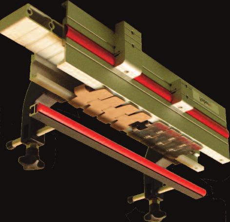
4 Pieds-Legs-Ständer Guides-Führungen CAB, CAB-SB Slat chain conveyors Standard Economical Easily expandable Silent For transporting unitary products Widths 45 to 300 mm (aluminium structure) and 65 to 105 mm ( stainless steel structure) Tough Open or monobloc structure Difficult conditions (dust, chips, etc.) Unitary or overpacked products Widths 70 to 196 mm 4 30 YEARS EXPERIENCE


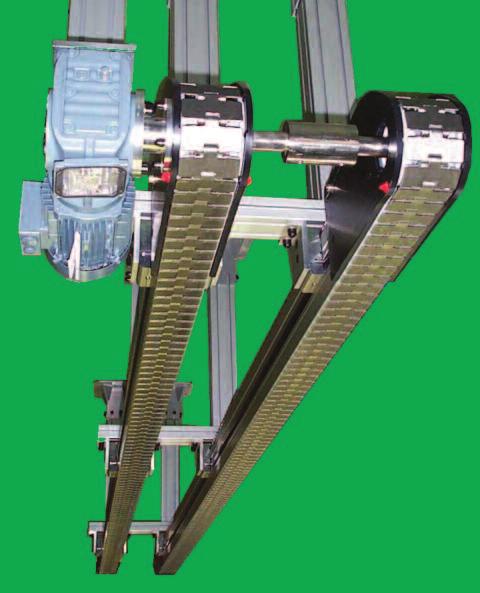
5 Modular belt conveyors 5 Tough Silent Easy to maintain Personnel safety Possibility of complex geometry Heavy loads Transport of overpacked products, boxes, etc. Widths 230 to 650 mm Straight conveyor with a smooth belt or a ball or roller belt Widths from 165 mm CAB Pieds-Legs-Ständer Guides-Führungen CAB, CAB-SB
6 Pieds-Legs-Ständer Guides-Führungen CAB, CAB-SB Summary of the conveyor ranges Choice guide table modular conveyors 6 page M 8 - «Flex» chains pages - beams and modules pages - F45 conveyors pages - CM conveyor, width 85 &FB conveyors, width 180 & 300 pages modular conveyors modular conveyors modular conveyors CAB & CAB-SB modular conveyors Conveyor width (mm) Chain or belt width (mm) Chain / Material Chain / belt 200 elastic Limit N F45 FK FS FM CM FC FL page M 43 page M 52 page M 64 page M & & 42 FlexToo FB 175 FB 295 R1 R2TB R2 R3TB R3 R ,5 82,5 114,3 190,5 190,5 304, ,2 609,6 152,4 500 N sauf avec axes plastiques POM chain 1250 N except with plastic pins POM POM or metal chain (stainless steel or steel) 2250 N except with plastic pins F2-750 F F F F POM belt + Kevlar reinforced wear heels Maximum weight of a product 1 kg 3 kg 6 kg 10 kg 15 kg 10 kg 15 kg Max speed m/mn Kinematic 10 m 25 m 15 m 30 m 35 m complexity 2000 N 3400 N 3500 N 3600 N 3800 N CAB Belt POM or PP according to width according to width Price variable Conditions Industry Clean, dry Agri-food (packaged products), Pharmacy, Cosmetics Oils - Temperature - Abrasive conditions (sugar, ceramic, dust, chips, etc.) Automotive, Mechanical, Heavy industries Cardboard dust Clean, dry Agri-food (packaged and overpacked products), Pharmacy, Cosmetics
7 Contents Lateral guiding page S 86 - Lateral guide profiles with metal frames pages - Lateral guides and intermediate roller and ball guides pages - Lateral guide profiles in aluminium pages - Guide holders pages - Height-adjustable mountings: - x-grf moulded mountings and spacer shims page - Assembly sheaves, angle connectors page - Width-adjustable mountings: x-grb & FGRF moulded mountings pages - Channel brackets and pins page - GH5 mountings page - Accessories pour et Cobral, fastenings page - Rotobloc-GL system page - Hardware and various accessories pages - Fixed and adjustable aluminium angle brackets pages - Width of passage with GH5 brackets page - Frontal guiding for page 88 & & & & & & & Legs for modular conveyors page S Structural tubes pages - Steel angle brackets for structural tubes page - Aluminium angle brackets for structural tubes page - Bases for square tube legs page - Fastenings on and Cobral beams page - Round tubes page - Bases for round tubes page - Square section legs pages - Ø 60.3 tube legs pages - legs page - Cable raceways page - Chutes for conveyors pages - Aluminium angle brackets for lateral fastening page - Adjustment modules for wedge conveyors page - Starter boxes page Reference index 7 page 114 & & & & CAB, CAB-SB Pieds-Legs-Ständer Guides-Führungen


8 Pieds-Legs-Ständer Guides-Führungen CAB, CAB-SB FLEXMOVE 8

9 Aluminium modular conveyors FLEXMOVE 9 Pieds-Legs-Ständer Guides-Führungen CAB, CAB-SB


10 Pieds-Legs-Ständer Guides-Führungen CAB, CAB-SB FlexMove & FlexInox Standard and economical, for isolated loads FlexMove conveyors adjust to all types of installation. 3D design Ready-to-assemble modules or conveyors assembled and tested in our workshops. FLEXMOVE FlexInox 10
 12,7 25,4 33,5 35,5 33,5 roll length 3 m 5 m 3 m More than a hundred chain variants for your specific needs. Structures and chains compatible and linkable with thousands of conveyors in service.")
11 FLEXMOVE FlexInox FlexMove & FlexInox Aluminium structures F45 FK FS FM CM FC FL FB 175 FB 295 Stainless steel structures SS SM SC Conveyor widths Chain pitches (+/- 1%) 12,7 25,4 33,5 35,5 33,5 roll length 3 m 5 m 3 m More than a hundred chain variants for your specific needs. Structures and chains compatible and linkable with thousands of conveyors in service. The most common modules and chains are available from stock. Quick and simple installation, transformation or modification. Small radii of curvature. Low noise. Oil collection channels, motorized transfers, cable raceways, control boxes, variable speed. 11 Pieds-Legs-Ständer Guides-Führungen CAB, CAB-SB
 Antistatic black acetal Kevlar reinforced acetal High temperature (100 C) PBT")


12 Pieds-Legs-Ständer Guides-Führungen CAB, CAB-SB Natural acetal Flat chains Material idem, with plastic pin (*) Antistatic black acetal Kevlar reinforced acetal High temperature (100 C) PBT Fibre glass reinforced acetal acetal, lubricated Anti-UV acetal PVDF (*) Chains with plastic pins: reduced elastic limit FLEXMOVE FlexInox 25.4 FK FS - SS FM - SM FC - SC 25,4 25,4 33,5 35,5 3,1 3,5 4 4, FKPC 5 FSPC 5 FMPC 5 FCPC 5 FKPC 5P FSPC 5P FMPC 5P FCPC 5P FKPC 5CD FSPC 5CD FMPC 5CD FCPC 5CD FKPC 5WR FSPC 5WR FMPC 5WR FCPC 5WR FSPC 5HT FMPC 5HT FCPC 5HT FSPC 5PBT FSPC 5GF FMPC 5GF FCPC 5GF FSPC 5LF FMPC 5LF FCPC 5LF FKPC 5UV FSPC 5UV FMPC 5UV FCPC 5UV FKPC 5PV FSPC 5PV E Safety chains Natural acetal chains Standard version High temperature (100 C) Antistatic black acetal Flat channels, safety chains For horizontal and sloping (< 5 ) transfers and accumulation conveying Series Pitch E W Colour White Black Yellow White Series Pitch E W Fig. 1 Fig. 2 Version with lateral roller Fig. 3 W 12 Pitch E W FM - SM FC - SC FL 33,5 35,5 35,5 5,5 6 7, FMPC 5V EMPC 5HT EMPC 5R FCPC 5V FCPC 5VHT FCPC 5VR FLPC 5V FLCD 5V

 Convex anti-slip insert on all links 3 Idem, (L= pitch of")
 Grooved anti-slip insert on all links D Idem, (L= pitch of")
 6 7 Stainless Steel 6 FLEXMOVE FlexInox Coated chains F.")


13 for horizontal or sloping transfer B 5 D E 6 Riveting detail 7 F...ST 5/-5S Series Coated natural acetal chains Pitch W Coating / accumulation impossible Figure Velvet grey flocking / fragile products 1 Flocking, colour to order Flat grey anti-slip insert on all links Idem, (L= pitch of coated links) 2 Translucent flat anti-slip insert / all links Idem, (L= pitch of coated links) Convex anti-slip insert on all links 3 Idem, (L= pitch of coated links) Anti-slip insert on all links Idem, (L= pitch of coated links) B LF acetal variant Flat anti-slip insert on all links Idem with lateral roller 5 Idem, (L= pitch of coated links) Grooved anti-slip insert on all links D Idem, (L= pitch of coated links) Short studded anti-slip insert / all links E Idem, (L= pitch of coated links) Coating / accumulation possible 50 HRC steel (for mechanical parts) 6 7 Stainless Steel 6 FLEXMOVE FlexInox Coated chains F...ST 5 NF FK FS - SS FM - SM FC - SC FL 25,4 25,4 33,5 35,5 35, FKFC 5 FSFC 5 FMFC 5 FCFC 5 FLFC 5V x x x x x FKFT 5 FSFT 5 FMFT 5A FCFT 5A FKFT 5-L FSFT 5-L FMFT 5A-L FCFT 5A-L FSFT 5A FSFT 5A-L FKFT 5C FSFT 5C FMFT 5 FCFT 5 FKFT 5C-L FSFT 5C-L FMFT 5-L FCFT 5-L FSFT 5B FMFT 5B FCFT 5B FSFT 5B-L FMFT 5B-L FCFT 5B-L FCFT 5B LF FLFT 5V EMFT 5R EMFT 5R-L FSFT 5D FMFT 5D FCFT 5D FSFT 5D-L FMFT 5D-L FCFT 5D-L FSFT 5E FMFT 5E FCFT 5E FSFT 5E-L FMFT 5E-L FCFT 5E-L FSST 5FA FMST 5FA FCST 5 FKST 5S FSST 5S FMST 5S FCST 5S FMST 5S NF FCST 5S NF 13 Pieds-Legs-Ständer Guides-Führungen CAB, CAB-SB
14 Pieds-Legs-Ständer Guides-Führungen CAB, CAB-SB W Series Pitch FLEXMOVE & FLEXinox W Figure Acetal chain, anti-stick surface 1 With magnetic insert 2 EA "universal acetal chain = centre distance 3 Idem, (L= pitch of universal links) Flat chain, radius 700 mm, acetal Flat chain, radius 700 mm, PBT 4 (*) Flat chain, radius 500 mm, acetal Flat chain, radius 700 mm, acetal 5 (*) Cradle chain Ø14, acetal 6 incompatible with horizontal curves Chains in... (POM = acetal)-> Flat chain, width 36 Flat chain, width 51 Flat chain, width 52 Flat chain, width 76 Series Pitch Figure 7 Special flat chains 5 6 x 65 Ø 14 FS - SS FM - SM FC - SC 25,4 33,5 35, FSPC 5 R FSPC 5 R PBT FK FSNS 5 Øa 18,5 FSMT 5 FMMT 5 FCMT 5 FSUC 5 Øa =5 EA=45 x=3,3 FMUC 5 Øa =6 EA= 50 x=3 FSUC 5-L FMUC 5-L FSPC 5 R700 FSPC 5 R700 PBT FMPC 5 R500 FMPC 5 R700 (*) Chains incompatible with intermediate drives FMB14 5 FS - SS 25,4 25,4 POM W PBT W POM W PBT W 14 hole Ø 3.1 *References of width 76 mm require special drive modules, and curves R 500 mm FSPC FSPC 5 36 PBT 36 FSPC FSPC 5 51 PBT 51 FSPC FSPC 5 52 PBT 52 FSPC FSPC 5 76 PBT * 76

15 H H Acetal chains Series Pitch FLEXMOVE & FLEXinox W Figure Slat insert 1 Flexible slat insert 2 Tubular insert 3 Tubular insert with 1 ply 4 "Brush insert for light loads (<1kg) Inclined tubular insert Wedge chains References for each chain link fitted with an insert, dimension H taken above the slat. H H FK FS - SS FM - SM 25,4 33, H H H FSWT 5BA 30 FMWT 5B 31,3 FSWT 5B 28 FKWT 5D 25 FSWT 5D 25 FMWT 5DC 25 FKWT 5C 30 FSWT 5C 30 FMWT 5C 30 FKWT 5DA 30 FSWT 5DA 30 FMWT 5DA 30 FKWT 5A 12,5 FSWT 5A 13 FMWT 5A 10,8 FKWT 5DB 25 FSWT 5DB H H Pieds-Legs-Ständer Guides-Führungen CAB, CAB-SB

 1 row of rollers Ø35 on")


 6 3 FCRT 5 (L=93) FSRC")


16 Pieds-Legs-Ständer Guides-Führungen CAB, CAB-SB ,5 62 L Acetal chains with... Ø 35 2 rows of rollers Ø10.4 on each link 1 row of rollers Ø18 on each link Same as pitch = (roller lug function) 1 row of rollers Ø35 on each link Same as pitch = (roller lug function) 1 row of rollers Ø20 on each link Same as pitch = (roller lug function) 1 row of rollers Ø11 on each link Same as pitch = (roller lug function) Ø 10,4 FLEXMOVE FlexInox Roller chains Lug / roller chains Series Pitch W Figure FS - SS FM - SM FC - SC FL 25,4 33,5 35,5 35, FMRT 5 (L=72) 6 3 FCRT 5 (L=93) FSRC 5A (L=39) FMRC 5A (L=60) FCRC 5A (L=60) FSRC 5A L FSRT 5 FSRT 5 L 16 Ø 20 FCRC 5A L FLRT 5V FMRC 5B FCRC 5B FLRC 5VB FMRC 5B L FMRC 5C FMRC 5C L 23 L Ø 18 15,5 54 FCRC 5B L Ø 11


17 1,5 C W Chains in... (POM = acetal)-> Chain with R 4.5 groove Reduced width variant Chain with domed reliefs Reduced width variant Increased width variant Grooved chains or chains with domed relief Ø 9 Series Pitch Figure C FLEXMOVE FlexInox B Usual Application: transport of cigarettes, same reference for every chain link B W 3 14,5 *References of width 76 mm require special drive modules, and curves R 500 mm FK FS - SS 25,4 25,4 POM W PBT W POM W PBT W FKCT 5C 44 FSCT 5C 63 FSCT 5C PBT 63 FSCT 5C FSCT 5C 51 PBT 51 FKCT 5B 43 FKCT 5B PBT 43 FSCT 5B 63 FSCT 5B PBT 63 FKCT 5B FSCT 5B FSCT 5B 51 PBT FSCT 5B 76 * 76 FSCT 5B 76 PBT * 76 Pieds-Legs-Ständer Guides-Führungen CAB, CAB-SB
18 Pieds-Legs-Ständer Guides-Führungen CAB, CAB-SB F Lo FL 12 FR 12 E Acetal chains Chain width = Lug width Thickness of thin lug Thin lug chains Thick lug chains Inclined lug chains Curved lug chains (*) L 50,8 mm (**) L 67 mm H FLEXMOVE FlexInox Wide lug chains (same width as the link) Horizontal or sloping transfer, without accumulation References for lug link with a pitch L (multiple of the pitch of the chain) D H 12,5 Series Pitch W Lo Figure F D FL FR E FK FS - SS FM - SM 25,4 25,4 33, ,5 H H H FKCT 5F3 L 3 FSCT 5F15 L 15 FMCT 5F15 L 15 FKCT 5F5 L 5 FMCT 5F20 L 20 FKCT 5F9 L 9 FSCT 5F30 L 30 FMCT 5F30 L FSCT 5FL12 L 12 FSCT 5FR12 L 12 FSCT 5E55 L (*) 55 FMCT 5D40 L 40 FMCT 5D60 L(**) 60 FMCT 5D80 L(**) 80
 Horizontal or sloping transfer, without accumulation of small products (lateral guiding positioned above the smooth")

19 Acetal chains Chain width Lug width Thin lug chain Thick lug chain 4 J La FLEXMOVE FlexInox Narrow lug chains (width less than the width of the link) Horizontal or sloping transfer, without accumulation of small products (lateral guiding positioned above the smooth part of the chain) References for lug link at pitch L (multiple of the chain pitch) Series Pitch W La Figure J K 6 FK 25, K H FKCT 5J6 L 6 FKCT 5K3 L 3 FKCT 5K5.5 L 5,5 FKCT 5K9 L 9 FKCT 5K20 L 20 FKCT 5K27 L La H Pieds-Legs-Ständer Guides-Führungen CAB, CAB-SB
 H Series Pitch W Figure FLEXMOVE FlexInox 1 2 Figure G Figure D FS - SS FM - SM FC - SC 25,4 33,5 35,5 63 83 103 H J = 8 J = 8 J =")
20 Pieds-Legs-Ständer Guides-Führungen CAB, CAB-SB 1 G D J 56 H H H 51, Acetal chains Open lug chains Closed lug chains Lug chains Horizontal or sloping transfer, without accumulation References for lug link with a pitch L (multiple of the pitch of the chain) H Series Pitch W Figure FLEXMOVE FlexInox 1 2 Figure G Figure D FS - SS FM - SM FC - SC 25,4 33,5 35, H J = 8 J = 8 J = 15,5 4 FSCT 5A4 L 5,5 FSCT 5A5.5 L 9 FSCT 5A9 L 12 FSCT 5A12 L 15 FSCT 5A15 L FMCT 5A15 L FCCT 5A15 L 17 FSCT 5A17 L FMCT 5A17 L FCCT 5A17 L 20 FCCT 5A20 L 30 FSCT 5A30 L FMCT 5A30 L FCCT 5A30 L 40 FSCT 5A40 L FCCT 5A40 L H 12 FSCT 5G12 L H 5 FSCT 5D5 L 12 FSCT 5D12 L 15 FSCT 5D15 L 30 FSCT 5D30 L 20
 or sloping transfer (Figure 4) References for each identical chain link Series")

21 H Acetal chains FLEXMOVE FlexInox 3 H 5 Rib chains For wet conditions. Horizontal (improved sliding) or sloping transfer (Figure 4) References for each identical chain link Series Pitch W Figure Rib h=3 1 Rib h= Rib + support h=35 3 Sloping reliefs 4 Rib h=15 5 FS - SS FM - SM FC - SC 25,4 33,5 35, FSRB 5C (H=12) 21 26,5 FMRB 5A FMRB 5B FMRB 5C (H=15,4) FMRB 5D FCRB 5A FCRB 5B 35 Pieds-Legs-Ständer Guides-Führungen CAB, CAB-SB


22 Pieds-Legs-Ständer Guides-Führungen CAB, CAB-SB A H D H Acetal chains V at Series Pitch W Figure 120 A D 120 with a flat in the bottom of the V F H FLEXMOVE FlexInox B C E V-shaped chains Horizontal or sloping transfer of cylindrical products References for each identical chain link H B E H 62 C F FK FS - SS FM - SM FC - SC 25,4 25,4 33,5 35, FSCV 5A 13 FKCV 5B 15 FSCV 5B 16 FMCV 5B 17 FCCV 5B 17 FKCV 5C 25 FSCV 5C 14 FSCV 5D 15 FSCV 5E 13 FSCV 5F 22 H

23 Chains with flange(s) or longitudinal grooves References for each identical chain link 1 Acetal chains Chain with transverse groove Groove width 15 mm depth 0.7 mm H Series Pitch W FLEXMOVE FlexInox 2 Series Pitch W Figure A flange on both sides 1 A flange on the left side 2 A flange on the right side 3 Flanged chain Grooved chain FK FS - SS 25,4 25, H=3 H=6 H=18 FK2R 5 3 FK2R 5 6 FS2R 5 18 FKRG 5 3 FKRG 5 6 FKRD 5 3 FKRD 5 6 FK 25,4 44 FKTR H H 3 Pieds-Legs-Ständer Guides-Führungen CAB, CAB-SB


24 Pieds-Legs-Ständer Guides-Führungen CAB, CAB-SB Conveyor profile sections W H H2 Width of the conveyor / W profile section FLEXMOVE Conveyor profile sections, intervention modules 1 H Series Reference Fig. 1 Strengthened variant Fig. 2 Height H aluminium profile only Heights H1 / H2 (standard chain) Standard lengths FK FS FM FC FL 45 / / / / / 150 KPS SPS MPS CPS Intervention modules They facilitate accessibility for dismantling and reassembly of the chain. Conveyor width W Fig. 3 Series Single intervention module 1 Double intervention module FCCB 3R FLCB / / / / / 94 3 et 6 m 3 m FK FS FM FC FL FKCC 160 FSCC 160 FMCC 160 FCCC 160 FLCC FMCC 160D 2 FL
 90 idler Reference Dimensions 3 Transfer kits for end modules Rollers alone (acetal Ø11): FAFR 11 For standard end modules")

 Series Figure Removable roller transfer kit 3 Removable plate transfer kit 4")
 (FMIE 85 FMDD 85... FMDD GP...) (FCIE 105 FCDD 105.")
 FKTB A45F FSTB A65F FMTB A85F FCTB A105F FLTB A150F FKTB A45PF FSTB A65PF FMTB A85PF FCTB A105PF FLTB A150PF (FSIE A65) (FSDD A65.")
 (FLSD.")
25 1 Standard models H FLEXMOVE W Series Figure Standard end idler 1 Dimensions (H = including standard chain) Compact versions Compact end idler 2 Dimensions (H = including standard chain) 90 idler Reference Dimensions 3 Transfer kits for end modules Rollers alone (acetal Ø11): FAFR 11 For standard end modules (do not fit on compact versions) Roller transfer kit (standard) Plate transfer kit (standard) L (except chain) FK FS FM FC FL FSIE A65 FMIE A85 FCIE A105 FLIE A150 L = 320 ; H =158 ; W = 65 L = 320 ; H = 160 ; W = 85 L = 325 ; H = 170 ; W = 105 FKIE 200 FSIE 200 FMIE 260P FCIE 280P L = 200 ; H = 101; W = 45 L = 200 ; H = 102 ; W = 65 L = 256 ; H = 132 ; W = 85 L = 275 ; H = 138 ; W = 105 FSIB 206 FMIB 300 FCIB 350 L = 200 ; W = 65 L = 300 ; W = 93 L = 350 ; W = For new standard end modules (do not fit on compact versions) Series Figure Removable roller transfer kit 3 Removable plate transfer kit 4 For end modules with transmission Roller transfer kit 1 Plate transfer kit 2 For compact idler modules -> Roller transfer kit 1 Plate transfer kit 2 H W 2 Idler modules Transfer kits L L = 325 ; H = 174 ; W = 155 FK FS FM FC FL (FSIE 65 FSDD FSDD GP...) (FMIE 85 FMDD FMDD GP...) (FCIE 105 FCDD FCDD GP...) (FLIE 325 FLDD... FLDD GP...) FKTB A45F FSTB A65F FMTB A85F FCTB A105F FLTB A150F FKTB A45PF FSTB A65PF FMTB A85PF FCTB A105PF FLTB A150PF (FSIE A65) (FSDD A65...) (FMIE A85) (FCIE A105) (FLIE A150) FSTB A65 FMTB A85 FCTB A105 FLTB A150 FSTB A65P FMTB A85P FCTB A105P FLTB A150P (FKSD...) (FSSD...) (FMSD...) (FCSD...) (FLSD...) FKTB 45SD FSTB 65SD FMTB 85SD FCTB 105SD FLTB 150SD FKTB 45PSD FSTB 65PSD FMTB 85PSD FCTB 105PSD FLTB 150PSD (FKIE-45) (FSIE-200) (FMIE-260P) (FCIE-280P) FKTB 200 FSTB 200 FMTB 260 FCTB 280 FKTB 200P FSTB 200P FMTB 260P FCTB 280P 25 3 L W Pieds-Legs-Ständer Guides-Führungen CAB, CAB-SB


 Maximum tensile force Gear motor on the left Gear motor on the right Dimensions (H = including standard chain) Gear (Z=Nbr of teeth) Maximum tensile force Guard")
 (FMIE A85) (FCIE A105) FSIE-PCB FMIE-PCB FCIE-PCB (FSDD...) (FMDD...) (FCDD.")
26 Pieds-Legs-Ständer Guides-Führungen CAB, CAB-SB FLEXMOVE D G FK FS FM FC FL FKDD A45 0L FSDD A65 0L FMDD A85 0L FCDD A105 0L FLDD A150 0L FKDD A45 0R FSDD A65 0R FMDD A85 0R FCDD A105 0R FLDD A150 0R L = 320 ; H = 250 ; W = 57 L = 320 ; H = 265 ; W = 65 L = 320 ; H = 265 ; W = 85 L* L = 325 ; H = 265 ; W = 105 H* W L = 325 ; H = 285 ; W = 155 Z16 Øp 130,2 Z16 Øp 130,2 Z12 Øp 129,4 Z12 Øp 137,2 Z12 Øp 137,2 500 N 500 N 1250 N 1250 N 1250 N Compact models (intended for SEW WAF10 gear motors, shaft Ø16, flange Ø80) Series FK FS FM FC FL Protection plate for chain winding Drive modules for all of these modules, the motors have to be ordered separately. Multi-track modules to order. Standard models (intended for SEW WAF20 or WAF30 gear motors, shaft Ø20, flange Ø120) Gear motor on the left Gear motor on the right Dimensions (*) excluding chain Gear (Z=Nbr of teeth) Maximum tensile force Gear motor on the left Gear motor on the right Dimensions (H = including standard chain) Gear (Z=Nbr of teeth) Maximum tensile force Guard plate Series Figure G D Figure G D Series Figure For idler modules -> For direct drive modules -> Guard plate FKDD 250 0L FKDD 250 0R L = 250 ; H = 160 ; W = 51 FSDD 250 0L FSDD 250 0R L = 250 ; H = 162 ; W = 65 Z11 Øp 90 Z11 Øp N 500 N FS FM FC (FSIE A65) (FMIE A85) (FCIE A105) FSIE-PCB FMIE-PCB FCIE-PCB (FSDD...) (FMDD...) (FCDD...) FSDD-PCB FMDD-PCB FCDD-PCB 26
 Gear motor on the left Gear motor on the right Dimensions (H =")

27 G G FLEXMOVE L* Drive modules for all these modules, the motors have to be ordered separately. Multi-track modules to order. Variants without slack strand for wedge conveyors Standard models (intended for SEW WAF20 or WAF30 gear motors, shaft Ø20, flange Ø120) Gear motor on the left Gear motor on the right Dimensions (H = including standard chain) Gear (Z=Nbr of teeth) Maximum tensile force Series Figure G D H* D D FK FS FM FC FL FKDD A45GP 0L FSDD A65GP 0L FMDD A85GP 0L FCDD A105GP 0L FLDD A150GP 0L FKDD A45GP 0R FSDD A65GP 0R FMDD A85GP 0R FCDD A105GP 0R FLDD A150GP 0R L = 320 ; H = 160 ; W = 57 L = 320 ; H = 162 ; W = 65 L = 320 ; H = 162 ; W = 85 L = 325 ; H = 171 ; W = 105 L = 325 ; H = 176 ; W = 105 Z16 Øp 130,2 Z16 Øp 130,2 Z12 Øp 129,4 Z12 Øp 137,2 Z12 Øp 137,2 500 N 500 N 1250 N 1250 N 1250 N Drive modules with transmission and adjustable torque limiter Standard support plate intended for SEW W30, S37 gear motors in the horizontal position. Transmission by 08B roller chain (pitch =12.7 mm, 3m included by module) gears: 19 teeth; Ø prim = mm. Gear motor on the left Gear motor on the right Dimensions (*) excluding chain Gear (Z=Nbr of teeth) Maximum tensile force Series Figure G D FK FS FM FC FL FKSD A45 0L FSSD A65 0L FMSD A85 0L FCSD A105 0L FLSD A150 0L FKSD A45 0R FSSD A65 0R FMSD A65 0R FCSD A105 0R FLSD A150 0R L = 320 ; H = 278 ; W = 57 L = 320 ; H = 265 ; W = 77 H* L* L = 320 ; H = 265 ; W = 97 L = 320 ; H = 265 ; W = 117 L = 325 ; H = 285 ; W = 166 Z16 Øp 130,2 Z16 Øp 130,2 Z12 Øp 129,4 Z12 Øp 137,2 Z12 Øp 137,2 500 N 500 N 1250 N 1250 N 1250 N 27 L* 65 H* W Pieds-Legs-Ständer Guides-Führungen CAB, CAB-SB
 (intended for SEW WAF20 or WAF30 geared motors, shaft Ø20, flange Ø120) (drive pinion on the lower strand of the chain, tensile force max")
 FCID DD 0R L = 380 ; H = 280 ; W = 57 H L = 380 ; H = 280 ; W = 77 W D L = 465 ; H = 300 ; W = 97 E W L = 465 ; H = 300 ; W = 117 Z11 Øp 90 Z11 Øp 90 Z9 Øp 98 Z9 Øp 104 FK FS FM FC FKID")
 Standard support plate intended for SEW W30, S37 gear motors in the horizontal position, max.")
28 Pieds-Legs-Ständer Guides-Führungen CAB, CAB-SB G F FLEXMOVE Intermediate drive modules for all these modules, the motors have to be ordered separately. Multi-track modules to order. Direct intermediate drive modules without torque limiter (*) (intended for SEW WAF20 or WAF30 geared motors, shaft Ø20, flange Ø120) (drive pinion on the lower strand of the chain, tensile force max 200 N) Gear motor on the left Gear motor on the right Dimensions Gear (Z=Nbr of teeth) Figure Series G D L L H FK FS FM FC FKID DD 0L FSID DD 0L(*) FMID DD 0L (*) FCID DD 0L FKID DD 0R FSID DD 0R(*) FMID DD 0R(*) FCID DD 0R L = 380 ; H = 280 ; W = 57 H L = 380 ; H = 280 ; W = 77 W D L = 465 ; H = 300 ; W = 97 E W L = 465 ; H = 300 ; W = 117 Z11 Øp 90 Z11 Øp 90 Z9 Øp 98 Z9 Øp 104 FK FS FM FC FKID SD 0L FSID SD 0L (*) FMID SD 0L (*) FCID SD 0L FKID SD 0R FSID SD 0R (*) FMID SD 0R (*) FCID SD 0R L = 380 ; H = 280 ; W = 57 (*) Not compatible with closed chains (R500 and R700), items 4 and 5 of page 14 Intermediate drive modules with transmission and adjustable torque limiter (*) Standard support plate intended for SEW W30, S37 gear motors in the horizontal position, max. tensile force 200 N Transmission by 08B roller chain (pitch =12.7 mm, 3m included per module) gears: 19 teeth; Ø prim = mm. Gear motor on the left Gear motor on the right Dimensions Gear (Z=Nbr of teeth) Figure Series F E L = 380 ; H = 280 ; W = 77 L = 465 ; H = 300 ; W = 97 L = 465 ; H = 300 ; W = 117 Z11 Øp 90 Z11 Øp 90 Z9 Øp 98 Z9 Øp (*) Not compatible with closed chains (R500 and R700), items 4 and 5 of page 14
 (drive gear under the upper strand of the chain, the")

 Transmission by 08B roller chain (pitch =12.")
 Maximum tensile force Figure Series F E 65 H (Excl.")
29 G F FLEXMOVE Catenary drive modules for all these modules, the motors have to be ordered separately. Multi-track modules to order. Drive modules with direct catenary, without torque limiter (intended for SEW WAF20 or WAF30 geared motors, shaft Ø20, flange Ø120) (drive gear under the upper strand of the chain, the conveyor has no return strand) Gear motor on the left Gear motor on the right Dimensions Gear (Z=Nbr of teeth) Maximum tensile force Figure Series G D L FK FS FM FC FKCD DD 0L FSCD DD 0L FMCD DD 0L FCCD DD 0L FKCD DD 0R FSCD DD 0R FMCD DD 0R FCCD DD 0R L = 670 ; H = 560 ; W = 57 L H L = 670 ; H = 560 ; W = 77 D L = 675 ; H = 567 ; W = 97 L = 685 ; H = 560 ; W = 117 Z16 Øp 133,8 Z12 Øp 129,4 Z12 Øp 137,2 500 N 1250 N Catenary drive modules with transmission and adjustable torque limiter Standard support plate intended for SEW W30, S37 gear motors in the horizontal position. (drive gear under the upper strand of the chain, the conveyor has no return strand) Transmission by 08B roller chain (pitch =12.7 mm, 3m included per module) gears: 19 teeth; Ø prim = mm. Gear motor on the left Gear motor on the right Dimensions Gear (Z=Nbr of teeth) Maximum tensile force Figure Series F E 65 H (Excl. motor) FS FM FC FSCD SD 0L FMCD SD 0L FCCD SD 0L FSCD SD 0R FMCD SD 0R FCCD SD 0R L = 670 ; H = 560 ; W = 77 L = 675 ; H = 567 ; W = 97 L = 685 ; H = 560 ; W = 117 Z16 Øp 133,8 Z12 Øp 129,4 Z12 Øp 137,2 500 N 1250 N 29 W W E Pieds-Legs-Ständer Guides-Führungen CAB, CAB-SB

 to order Lengths of the straight portions L L x L FK FS FM FC FL FKWB... FSWB... FMWB... FCWB... FLWB.")

30 Pieds-Legs-Ständer Guides-Führungen CAB, CAB-SB FLEXMOVE r Curves with wheels Curve modules with wheels These modules allow friction-free chain guiding. The wheels are made from fibre glass reinforced nylon and are held by double sealed ball bearings ensuring durability and minimum friction. Linking fish plates included in each module. Mean radius r Series Angle x Figure Other angles (x ) to order Lengths of the straight portions L L x L FK FS FM FC FL FKWB... FSWB... FMWB... FCWB... FLWB... FKWB 30R150A FSWB 30R150A FMWB 30R160A FCWB 30R170A FLWB 30R210A FKWB 45R150A FSWB 45R150A FMWB 45R160A FCWB 45R170A FLWB 45R210A FKWB 60R150A FSWB 60R150A FMWB 60R160A FCWB 60R170A FLWB 60R210A FKWB 90R150A FSWB 90R150A FMWB 90R160A FCWB 90R170A FLWB 90R210A FKWB 180R150A FSWB 180R150A FMWB 180R160A FCWB 180R170A FLWB 180R210A FKWB xr150a FSWB xr 150 A FMWB xr160a FCWB xr170a FLWB xr 210 A FKWB: It is not possible to fit these curves directly on drive modules FKDD and FKSD or idler FKIE. A straight module must be fitted between them

.")
31 1 FLEXMOVE Curved drive modules Curved drive modules, with sprocket, 180 : These modules enable the motorization of "carousel conveyors. An intervention module F...CC-160 is required. The gear motor is positioned horizontally under the module, by direct fitting or with transmission. The position of the motor, direction of rotation (clockwise / anticlockwise to be specified on the order); gear motor and connection flange to be ordered separately. Allowable forces 200 N. Linking fish plates included in each module (references of the fishplates the same as those of the curves with wheels above). Direct curved drive modules, without torque limiter (intended for SEW WAF20 or WAF30 geared motors, shaft Ø20, flange Ø120) Primitive radius / sprocket (Z= number of teeth) Series Figure 1 FK FS FM FC FKWD DD 0M FSWD DD 0M FMWD DD 0M FCWD DD 0M 150 mm / Z mm / Z mm / Z mm / Z30 Curved drive modules with transmission and torque limiter Standard support plate intended for SEW W30, S37 gear motors in the horizontal position Series Figure 2 Primitive radius / sprocket (Z= number of teeth) FK FS FM FC FL FKWD SD 0M FSWD SD 0M FMWD SD 0M FCWD SD 0M FLWD SD 0M 150 mm / Z mm / Z mm / Z mm / Z mm / Z Pieds-Legs-Ständer Guides-Führungen CAB, CAB-SB
.")
.")
.")

 and FCHB 90 R 500 (figure 3) Series Angle x Radius y mm References of the modules (angle x")
 150 (mini) - 300-500 250 (mini) - 500-700 1 300 (mini)- 500-700-1000")

32 Pieds-Legs-Ständer Guides-Führungen CAB, CAB-SB FLEXMOVE Curves on slip rails: Horizontal & articulated horizontal Horizontal curves on slip rails: These modules are made by bending 2 aluminium half-profile sections with spacers (figure1). They allow reduced volume thanks to the absence of rotating plates, but create additional friction. We recommend a verification of the tensile forces applied to the chain (our Design Office is at your disposal). Tolerance +/- 1 mm for the radius and +/- 1 for the angle. All angles and radii can be produced to order (see example of concentric curves below). Linking fish plates included in each module. In the event of significant forces or high speed, a bendable wear profile section in PA6 can be mounted on the inside using M5x10 screws (Figure 4). Examples: FCHB 30 R 500 (figure 2) and FCHB 90 R 500 (figure 3) Series Angle x Radius y mm References of the modules (angle x Radius y mm) Example of a reference (Angle 90 Radius 500 mm) Standard lengths of the straight portions L Linking fish plates included in each module. FK FS FM FC FL standard: 15, 30, 45, 60, 90, 180 (autres sur demande) 150 (mini) (mini) (mini) (mini) FKHB.x R y FSHB.x R y FMHB.x R y FCHB.x R y FLHB.x R y FKHB 90 R 500 FSHB 90 R 500 FMHB 90 R 500 FCHB 90 R 500 FLHB 90 R 500 FACS 20x140 FKHB only: It is not possible to fit these curves directly on drive modules FKDD and FKSD or idler FKIE. A straight module must be fitted between them. Articulated horizontal curves on slip rails: References of the modules Linking fish plates included in each module. E.g.: Concentric curves Series ± FACS 25x140A FK FS FM FC FL FACS 20x FSHAB 5 FMHAB 5 FCHAB 5 FACS 25x140A

 Series Angle x Radius R (mm) Example of a reference (angle 7 ) Standard lengths of the straight portions L Linking fish plates included in each module.")
33 FLEXMOVE Curves on slip rails: Vertical & articulated vertical Vertical curves on slip rails: Vertical curves enable a change in slope of the conveyors. Like all curves on slip rails, they cause additional friction. Standard aluminium curves, kept in stock. These modules are made by bending aluminium beam section on which is fitted the slip profile in continuity of the upstream and downstream modules. References of the modules (angle x ) Series Angle x Radius R (mm) Example of a reference (angle 7 ) Standard lengths of the straight portions L Linking fish plates included in each module. R 80 FK FS FM FC FL standard: 5, 7, 10, 15, 30, 45, 90 (autres sur demande) FKVB...x R 300 FSVB...x R 300 FMVB...x R 400 FCVB...x R 400 FLVB...x R 500 FKVB 7 R 300 FSVB 7 R 300 FMVB 7 R 400 FCVB 7 R 400 FLVB 7 R 500 FACS 20x140 For angles < 2, a simple bias cut can be made on straight beams, with fish plating by FACS-20X140 Articulated vertical curves on slip rails: This module allows you to adjust the slope of a straight section, for example, to adapt it to the height of the vials. Angles and straight parts made to order. References of the Modules Linking fish plates included in each module. Series 80 FACS 25x140A FK FS FM FC FL FKVAB 5 FSVAB 5 FMVAB 5 FCVAB 5 FACS 20x ± 5 FACS 25x140A 163 approx. Pieds-Legs-Ständer Guides-Führungen CAB, CAB-SB


34 Pieds-Legs-Ständer Guides-Führungen CAB, CAB-SB FLEXMOVE FS, FM and FC conveyor ranges Helical or twisted curves on slip rails Helical curves allow space saving along with a change of direction and level. They are produced by bending, usually at a radius 500 mm. The usual angle is 90, 180, or even 360. At the beginning and end of a helical curve, a vertical curve enables connection to horizontal parts. It is also possible to prepare for the beginning and/or the end of a sloping conveyor. Our Design Office is at your disposal to validate your requirement. The twisted curves enable products to be referenced along the lateral guide, or products to be turned over. Our Design Office is at your disposal to validate your requirement. Vertical curve, 5 or 7 34 DH Slope ΔH for curve in Rm angle at 90 at 180 at Helical curve Vertical curve, 5 or 7


35 F45 chain range FLEXMOVE 35 Pieds-Legs-Ständer Guides-Führungen CAB, CAB-SB


36 Pieds-Legs-Ständer Guides-Führungen CAB, CAB-SB FLEXMOVE FACS 11x100 FACS 50 F45 F45PC 3 F45CV 3E F45FT 3 F45FC 3 F45WT 3C F45CB Beam Packaging: 3 m bar; (recuts to order) Slip profile: F45SR 25H (PEHD+PA6 grey) Fish plates Figure lateral 1 central 2 Acetal chains, pitch 12.7 mm Figure Natural acetal flat chain 1 V-Form, Chain with insert 3 Flocked chain 4 Slat chain 5 F45 conveyor range * Direction of travel * With F45 PC3 chain 7 43 Elastic Limit 200 N Max speed 20m/min Packaging: Roll of 3 m Applications: light products Maximum conveyor length: 6 m NEW


37 Idler module F45IE tooth sprocket Drive modules (usable with the shaft protruding on the right or the left) 10-tooth gear Motors to order, max. speed 20m/min ØA ØA Intermediate drive module F45ID 50 Reference F45DD 9 F45DD 12 FLEXMOVE F45 conveyor range Standard fitting Fitting with brushless motor Pieds-Legs-Ständer Guides-Führungen CAB, CAB-SB


38 Pieds-Legs-Ständer Guides-Führungen CAB, CAB-SB F45HB horizontal curves on slip rails Mean radius 150 or 300 mm, Straight portions of 40 mm, fish plates included F45VB vertical curves on slip rails Mean radius 400 mm, straight portions of 40 mm, fish plates included FLEXMOVE F45 conveyor range angle a angle a R = 150 F45HB 30R150 F45HB 45R150 F45HB 90R150 F45HB 180R150 R = 300 F45HB 30R300 F45HB 45R300 F45HB 90R300 F45HB 180R Other radii on request Other radii on request R = 300 F45HB 30R300 F45HB 45R300 F45HB 90R300 F45HB 180R300 R = 400 F45VB 5R400 F45VB 7R400 F45VB 15R400 F45VB 90R400

 H=17 5 H=30 Universal chain 6 Flat acetal chain, steel plated 7 Flat acetal chain + anti-slip insert on each link 8 9 Flocked chain 10 Thick lug chain (pitch.")

39 H 5 9 CM chain, width 83 mm not compatible with ranges FM and SM FB175 chains width 175 mm & FB295 chains width 295 mm Acetal chains Chain width Elastic limit (except with plastic pins) Natural acetal flat chain Idem with plastic pins: elastic limit 250N Acetal flat chain, antistatic black Wear-resistant chain A B FLEXMOVE 1 Series Pitch W Figure Natural acetal flat chain 15 Idem with anti-slip insert on each link 16 Antistatic chain 15 Roller lug chain Ø46 Closed chain 700 radius 3 V-chain H=16 4 H=9 H=12 Lug chain tabs H=15 (pitch...l) H=17 5 H=30 Universal chain 6 Flat acetal chain, steel plated 7 Flat acetal chain + anti-slip insert on each link 8 9 Flocked chain 10 Thick lug chain (pitch...l) H= Chain with insert covering the whole slat 12 Chain with tubular insert 13 Chain with translucent insert covering the whole slat H 12, H X design CM FB 175 FB N A = 9; B = 29.5 A = 9; B = 33 CMPC 5 CMPC 5P CMPC 5 CD CMPC 5WR FB175 PC 3A FB295 PC 3A FB175 FT 3A FB295 FT 3A FB175 CD 3A FB175 RC 3A CMPC 5R700 CMCV 5B CMCT 5A9 L CMCT 5A12 L CMCT 5A15 L CMCT 5A17 L CMCT 5A30 L CMUC 5 CMST 5 CMFT 5 CMFT 5C CMFC 5 CMCT5 D125L CMFT 5A CMWT 5C CMFT 5F Pieds-Legs-Ständer Guides-Führungen CAB, CAB-SB


40 Pieds-Legs-Ständer Guides-Führungen CAB, CAB-SB H2 W Width of the conveyor / W profile section Reference Height H1 aluminium profile only H2 CM range, width 85 mm Note: not compatible with the FM and SM ranges FB175 range, width 182 mm & FB295 range, width 300 mm Standard lengths Intervention module: Idler modules: CMCC-160 CMIE FLEXMOVE H1 150 Series Fig. 1 Fig. 2 Fig. 3 CM FB 175 FB CMCB 3 FB175 CB3 FB295 CB3 FB175 IE 325 FB295 IE m X design


 on request L CMWB 160 CMWB")


41 Drive modules: Direct drive modules with torque limiter: on the left on the right Direct drive modules without torque limiter: on the left on the right Curves with wheels: 4 FLEXMOVE Series Drive modules with transmission and torque limiter: on the left CM range, width 85 mm Note: not compatible with the FM and SM ranges FB175 range, width 182 mm & FB295 range, width 300 mm on the right Mean radius r Angle x (x ) on request L CMWB 160 CMWB 30R160A CMWB 45R160A CMWB 90R160A CMWB 180R160A CMWB xr160a CM FB 175 FB 295 CMDD TL 0L CMDD TL 0R CMSD 0L CMSD 0R 41 FB175 DD 0L FB175 DD 0R L 2 x X design FB295 DD 0L FB295 DD 0R L Pieds-Legs-Ständer Guides-Führungen CAB, CAB-SB


 Standard lengths of the straight")


42 Pieds-Legs-Ständer Guides-Führungen CAB, CAB-SB CM range, width 85 mm Note: not compatible with the FM and SM ranges FB175 range, width 182 mm & FB295 range, width 300 mm Curves on slip rails: L x r L FLEXMOVE 42 CM FB175 VB FB295 VB , 45, 60, CMHB x R y FB 175 HB x R y FB 295 HB x R y CMHB 90 R 700 FB 175 HB 90 R 700 FB 295 HB 90 R FACS 20x r x Series Angle x Radius y mm References of the modules (angle x Radius y mm) Example of a reference (Angle 90 Radius 700 mm) Standard lengths of the straight portions L Linking fish plates included in each module. Vertical curves on slip rails: Series Angle x Mean Radius radius y mm References of the modules (angle x Radius y mm) Standard lengths of the straight portions L Linking fish plates included in each module. CM FB175 VB FB295 VB , 7, 15, 30, 45, 60, CMVB x R y FB175 VB x R y FB295 VB x R y 80 FACS 20x160 X design

43 Stainless steel modular conveyors Pieds-Legs-Ständer Guides-Führungen CAB, CAB-SB FlexInox 43


44 Pieds-Legs-Ständer Guides-Führungen CAB, CAB-SB Width Chains Chain pitch Slip profile Rivets Modules Drive module, shaft on the left FlexInox Range Item Drive module, shaft on the right 1 Drive module, shaft on the left without slack strand 2 Drive module, shaft on the right without slack strand 3 Direct intermediate drive, shaft on the left Direct intermediate drive, shaft on the right Idler module 4 Roller transfer kit Plate transfer kit FlexInox modular conveyors Presentation, end modules 44 These conveyors are made with a stainless steel structure, They accept Flex chains of series: FS-FM-CF. The sides are assembled by spacers with a pitch 500 mm fixed in slotted holes. They also allow for the mounting of accessories: guide brackets and legs. SS SM SC FS series FM series FC series FASR FASLS-M5 references SSDD 0L SMDD 0L SCDD 0L SSDD 0R SMDD 0R SCDD 0R SSDD GP 0L SMDD GP 0L SCDD GP 0L SSDD GP 0R SMDD GP 0R SCDD GP 0R SSID DD 0L SMID DD 0L SCID DD 0L SSID DD 0R SMID DD 0R SCID DD 0R SSIE 320 SMIE 320 SCIE 325 SSTB 65 SMTB 85 SCTB 105 SSTB 65P SMTB 85P SCTB 105P 4


45 FlexInox modular conveyors Straight modules, fish plating Straight beams Creations to order, up to 2 m long Range Beam reference Width L Beam height H Height HT chain included Range Intervention module reference L HT Intervention modules length 160 mm This module facilitates connection of the chain. FlexInox 45 SS SM SC SSCB SMCB SCCB SS SM SC SSCC 160 SMCC 160 SCCC 160 H Pieds-Legs-Ständer Guides-Führungen CAB, CAB-SB


46 FlexInox modular conveyors Curves with wheels & Vertical curves on slip rails Pieds-Legs-Ständer Guides-Führungen CAB, CAB-SB Curves with wheels: These modules provide friction-free chain guiding. The wheels are made from fibre glass reinforced nylon and are held by double sealed ball bearings ensuring durability and minimum friction. Average curve radius: see table below. Straight parts 160 mm Linking fish plates SACS-50x75 are delivered with each module. Creation of any curve with wheel from 5 to 180 to order, tolerance on the angle ± 1 Series R mean radius Angle Curve with wheels, 45 Series Angle FlexInox 45 SS SM SC Reference Reference Reference SSWB 30 R 150 SMWB 30 R 160 SCWB 30 R 170 SSWB 45 R 150 SMWB 45 R 160 SCWB 45 R 170 SSWB 60 R 150 SMWB 60 R 160 SCWB 60 R 170 SSWB 90 R 150 SMWB 90 R 160 SCWB 90 R 170 SSWB 180 R 150 SMWB 180 R 160 SCWB 180 R 170 S...WB-45R Curve with wheels, 180 S...WB-180R Vertical curves on slip rails: Vertical curves enable a change in slope of the conveyors. As all the curves on slip rails, they generate additional friction. These stainless steel curves accept the slip profiles in continuity of the upstream and downstream modules. 46 Curve with wheels, S...WB-90R... SS SM SC Reference Reference Reference SSVB 5R300 SMVB 5R400 SCVB 5R400 SSVB 10R300 SMVB 10R400 SCVB 10R400 SSVB 15R300 SMVB 15R400 SCVB 15R400 SSVB 30R300 SMVB 30R400 SCVB 30R


47 FlexInox modular conveyors Horizontal curves on slip rails These modules are made by bending of 2 stainless steel half-profile sections with spacers. They allow reduced volume thanks to the absence of rotating plates, but create additional friction. We recommend a verification of the tensile forces applied to the chain (our Design Office is at your disposal). Standard mean radii of the curve: 500 and 700 mm (and 300mm for SM series). Straight parts 200 mm. Linking fish plates included in each module. Tolerance +/- 10 mm for the radius and +/- 1 for the angle. Other angles and other radii can be produced to order. Series Mean radius R Angle Mean radius R Angle Mean radius R Angle Curve on slip rails, 30 S...HB-30R... R FlexInox 47 SS SM SC 300 Reference Reference Reference SMHB 7.5 R 300 SMHB 15 R 300 SMHB 30 R 300 SMHB 45 R 300 SMHB 60 R 300 SMHB 90 R Reference Reference Reference SSHB 7.5 R 500 SMHB 7.5 R 500 SCHB 7.5 R 500 SSHB 15 R 500 SMHB 15 R 500 SCHB 15 R 500 SSHB 30 R 500 SMHB 30 R 500 SCHB 30 R 500 SSHB 45 R 500 SMHB 45 R 500 SCHB 45 R 500 SSHB 60 R 500 SMHB 60 R 500 SCHB 60 R 500 SSHB 90 R 500 SMHB 90 R 500 SCHB 90 R Reference Reference Reference SSHB 7.5 R 700 SMHB 7.5 R 700 SCHB 7.5 R 700 SSHB 15 R 700 SMHB 15 R 700 SCHB 15 R 700 SSHB 30 R 700 SMHB 30 R 700 SCHB 30 R 700 SSHB 45 R 700 SMHB 45 R 700 SCHB 45 R 700 SSHB 60 R 700 SMHB 60 R 700 SCHB 60 R 700 SSHB 90 R 700 SMHB 90 R 700 SCHB 90 R 700 Curve on slip rails, 90 S...HB-90R... R Pieds-Legs-Ständer Guides-Führungen CAB, CAB-SB
(2) 590 (2) 460 300 FS / 640 (1) 620 63 65 SS 800 790 620 790 FM 740 560 (3) 480 720 SM 83 85 160 800 800 800 640 320 640 CM 775 640 640 FC 800 690 (4) 500 730 103 105")

 with idler module, length 200 mm, (3) with special fish plating, (4) with idler module, length 280 mm, (5) with 2 curves of 90, without chutes.")
48 Pieds-Legs-Ständer Guides-Führungen CAB, CAB-SB A D Conveyor reference Chain width & conveyors Straight or curved, 90 : minimum dimensions L Conveyor width C F FK (1)(2) 590 (2) FS / 640 (1) SS FM (3) SM CM FC (4) SC FL FB FB Intervention modules, if any, can be added to the dimensions above: Dimensions calculated with minimum size idler modules and curves with wheels. Please consult our Design Office to validate these installations according to the application. FLEXMOVE FlexInox Mean radius of curves (1) with drive module, length 250 mm. (2) with idler module, length 200 mm, (3) with special fish plating, (4) with idler module, length 280 mm, (5) with 2 curves of 90, without chutes. (The chutes require longer straight sections). (6) with a single curve of C L A min B min C min C B A A D min (5) D (6)
.")


49 For series reference Material White HDPE PA6 + grey HDPE Black anti-static UHMW PE White PVDF PTFE (Teflon ) Stainless steel Installation recommendations for slip profile: (See fitting instructions and sketches below). - Provide 1 or 2 rivets or 1 or 2 plastic screws at the same slip band leading end. - Do not exceed a unit length of the profile of 3m and allow sufficient clearance for expansion: 0.2mm/m/ ) Conveyors Slip profiles CM Maximum F45 FK FS, FM, FB 175 temperature Figure FC, FL FB 295 of the profile section FASR 25K FASR 25U CMSR 25 1 CMSR 25B 2 60 C CMSR 3 3 F45SR 25H FASR 25KH FASR 25H CMSR 25H 100 C FASR 25KA FASR 25A CMSR 25A 60 C 1 FASR 25KP FASR 25P CMSR 25P 100 C FASR 1.2 T 220 C FASR 3X C Installation tool for slip rail profile Drilling Templates FLEXMOVE FlexInox Slip profile Attachment tools Aluminium rivets Smooth bore 49 Fitting pliers Applications Standard load++ Integral guide Chemical Abrasion Packaging roll of 25 m 3m bar roll of 25 m 1.2 m bar 3m bar PCPE Cutting pliers for PE profiles with maximum section of 30x10 or 20x12 Installation screw press for smooth rivets Plastic grub screw, length 6mm F45 GAB F45 ALU. RIVET 3X6.5 D3 F45 PRESS FK GAB FK Ø3 L6.5 SERT D3 D3 PRESS PAST M4x6 FSMR 140 FS, SS ALU. RIVET 4X6.5 FM, SM FMMR 140 SERT D4 D4 PRESS PAST M5x6 GAB FM Ø4 L6.5 FC, FL, SC FCMR 200 CM, FB175, FB295 FBMR 170 ALU. RIVET 4X8 PAST M5x8 Pieds-Legs-Ständer Guides-Führungen CAB, CAB-SB

, TC44, TC44-88, TC88 A L B 11 Zinc")
 B")


 3 4,5 19 50 28")

50 Pieds-Legs-Ständer Guides-Führungen CAB, CAB-SB Groove cover Groove cover reference For profile section e 1 FAAC 3P Rigid PVC, in 3 m bars FAAC 2 Aluminium in 2m bars FBSB... (Except FBSB- 40x40), TC44, TC44-88, TC88 A L B 11 Zinc plated steel fish plates HC screws included except (*) SACS 50x75 fish plates for (2P necessary for one fish plating) B FLEXMOVE FlexInox A Groove cover, fish plates, tooling for chain pins H FASC 25 Flexible PVC, in 25 m rolls TC64, KPS, SPS, MPS, CPS FLCB For FK, (FS, FM, FC, FL; ), FxDT chute FS, FM, FC, FL; FBCD cable raceways CM, FB 175; FB 295 AC2A8, AT30; FGLB, FGLR, FGRR 3x20x12 e A L B H 3 50 For series Reference Figure FACS 20x FACS 20x140A FACS 25x140A FACS 20x130A FACS 20x FACS 25x A Tools for inserting chain pins FK FS SS FACS 25x FBCS 19x50 (*) 3 4, FBCS 20x55 (*) 3 4, FBCS 13x e FM SM L A FC FL SC H CM FB 175 FB 295 FSMJ 4 FMMJ 6 FCMJ 6 FBMJ 6P 1 2 Reference figure e H L A B ØM 5 8
 FLEXMOVE FlexInox Standard gear motors The modules with lengths of 320-325 mm receive as standard WAF20, WAF30 & FAS 37 (hollow shaft) gear motors with flange Ø120.")


51 Modules with direct drive: &#! &"! &!! %! $! #! "!! )*+,-./0.-, /167 Tensile force (dan) FLEXMOVE FlexInox Standard gear motors The modules with lengths of mm receive as standard WAF20, WAF30 & FAS 37 (hollow shaft) gear motors with flange Ø120. The FAS 37/WAF30 gear motor requires an additional support leg. * FK and FS modules of length 250 mm receive as standard WAF10 (hollow shaft) gear motors with flange Ø 80. S37-SAF37 <750W W30-WAF30 750W W20-WAF20 550W WAF W* FM - FC - FL FK - FS! ' &! &' "! "' (! (' #! #' '! 89-0::0./;.2+48+<0;,.5=>=47 Conveyor speed (m/min) Modules with transmission: They are designed as standard for W30 or S37 (protruding shaft) gear motors. The S37 gear motor requires an additional support leg. Chain transmissions contain a torque limiter. The forces applied to the chain must be monitored, either by checking the motor current, or by precise adjustment of the torque limiters. For the calculation of forces and for other motor versions, do not hesitate to consult our design office. Intermediate drive modules or curves with sprockets (F...ID and F...WD): Maximum tensile forces are limited to 20 dan. Achievable speeds: Consult our Design Office 51 SAF37 S37 WAF20 WAF30 W30 WAF10, WAF20, W20, WAF30, W30, FAS37 and S37 types are SEW USOCOME products Pieds-Legs-Ständer Guides-Führungen CAB, CAB-SB

52 Pieds-Legs-Ständer Guides-Führungen CAB, CAB-SB FLEXTOO 52


53 Aluminium modular conveyors Pieds-Legs-Ständer Guides-Führungen CAB, CAB-SB FLEXTOO 53


 are common to all of our ranges and fit in the 2 lateral grooves.")
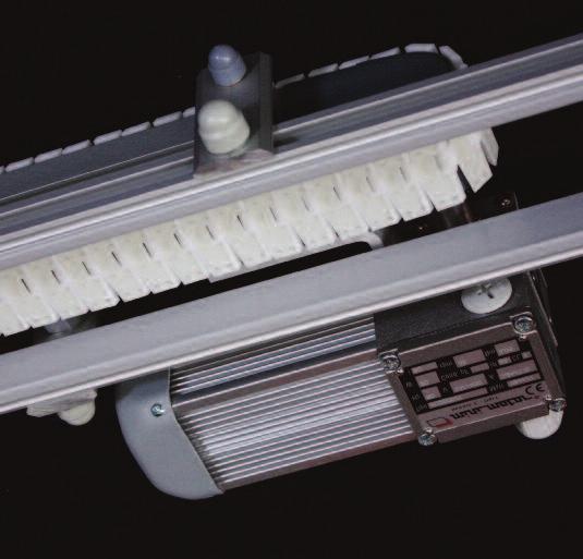
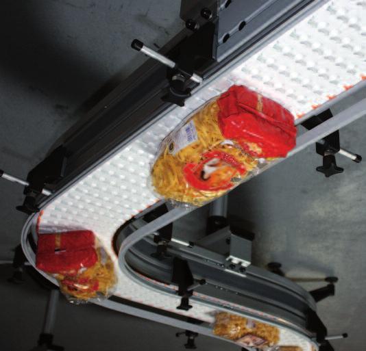
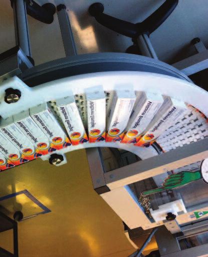
54 FlexToo conveyors Presentation of the range Tough and silent for conveying cartons & bulky products. is available in 5 widths: 227, 342, 418, 494, 647 mm Modularity. Robust structure and a very resistant belt permit complex and compact geometries. Silent. Optimum staff safety. Motorized transfers, Quick and easy maintenance Pieds-Legs-Ständer Guides-Führungen CAB, CAB-SB The many accessories (legs, guides, mountings, etc.) are common to all of our ranges and fit in the 2 lateral grooves. FLEXTOO 54 Designed for your installation requirements, FlexToo conveyors are assembled and tested in our workshops. Cable raceways integral to the conveyor.


")


 with integral")


55 A safe belt with a, pitch of 38.1 mm Low noise. Good wear resistance High tensile strength (including curves) Small radius of curvature Standard colour white FlexToo conveyors Presentation of the range FlexOne belt R W Direction of travel Blue colour to order F links (width mm) with integral stop, height width 273 mm Possibility of stops or special lugs to order. FLEXTOO Belt options Flocked velvet belt Additional equipment for the belt FONE-BUTH10 stops (50x25 Ht 10) snap-on on the belt 55 FONE-INSERT anti-slip inserts (50x25 th. 5.5) snap-on on the belt FONE-INSERT anti-slip short studded inserts (50x25 th. 5.5) snap-on on the belt Pieds-Legs-Ständer Guides-Führungen CAB, CAB-SB

 Conveyor reference F2 750 F2 1200 F2 1500 F2 1800 F2 2400 Belt, width W FLEXTOO A maximum tensile force* Drilling Templates Example of a Reference")

56 FlexToo conveyors Structures & straight modules Sectional view W 156 Slip profile: F2PG white F2PG-N black (inside of curves) FL5X CRF2 Groove cover FACS 25 optional Pieds-Legs-Ständer Guides-Führungen CAB, CAB-SB Conveyor reference * with slip profile made from special material in the inside of the curves. See table at the end of the chapter for the allowable tensile force according to the speed of the belt. Straight modules F2-xxxx-D... (standard length 3m, others to order) Conveyor reference F2 750 F F F F Belt, width W FLEXTOO A maximum tensile force* Drilling Templates Example of a Reference module length 3m F2 750 D3000 F D3000 F D3000 F D3000 F D3000 Conveyor, width A 56 Aluminum rivets Smooth bore Number of support profiles Installation screw press for smooth rivets Mean radius of curves R F N F N F N F N F N Plastic grub screw, length 6mm: GAB F2 ALU. RIVET 3X6.5 Ø3 L6.5 D3-F2 PRESS PAST M4x6 FACS-25x140A connecting fish plates not included
 80 FLEXTOO 180 radius average a 8 a 7 Intervention modules The F2-xxx-CC-180 module includes 1 removable area (above or below) allowing connection of the belt.")


57 FlexToo conveyors Curved modules & intervention modules Horizontal curved modules multiple angles of 15, (others to order) 200 Vertical curved modules mean radius 500 mm (angles to order) 80 FLEXTOO 180 radius average a 8 a 7 Intervention modules The F2-xxx-CC-180 module includes 1 removable area (above or below) allowing connection of the belt. The F2-xxx-2CC-400 module contains 2 removable areas (above and below) to be split for the delivery of a long conveyor while leaving the belt in place. The belt support profiles are extended from the upstream and downstream modules. Reference conveyor F2 750 F2 750 C400/ F F C640/ F F C800/ F F C930/ F F C1180/ F2 750 F2 750 CV F F CV F F CV F F CV F F CV FACS-25x140A fish plates included F2 750 F2 750 CC 180 F CC 180 F F CC 180 F CC 180 F F CC 180 F CC 180 F F CC 180 F CC 180 F F CC 180 F CC Conveyor reference Conveyor reference Ex. of reference of a curve, 90 Mean radius Connecting fish plates FACS-25x140A included E.g. of the reference of a curve, 15 Intervention module reference single (Figure 1) double (figure 2) FACS-25x140A connecting fish plates included Pieds-Legs-Ständer Guides-Führungen CAB, CAB-SB


 W W 50 Transfer reference to be fixed to idler modules transmission on the left transmission on the right F2 750 249 F2")

58 FlexToo conveyors Idler and transfers end modules Standard idler module Idler module with sprockets - for motorised transfer at conveyor input - for dusty conditions Pieds-Legs-Ständer Guides-Führungen CAB, CAB-SB Reference conveyor F2 750 F F F F FLEXTOO Reference idler module F2 750 R F R F R F R F R FACS-25x140A connecting fish plates included End transfer (not compatible with lugs or anti-slips inserts) Conveyor reference F2 750 F2 750 TG1R F2 750 TG2R F F TG1R F TG2R F F TG1R F TG2R F F TG1R F TG2R F F TG1R F TG2R Conveyor reference Reference of the transfer to be fixed to Idler or GP drive modules at the start of the between s Transfer reference to be fixed to drive modules at the end of the between s F2 750 F2 750 TG1M F2 750 TG2M F F TG1M F TG2M F F TG1M F TG2M F F TG1M F TG2M F F TG1M F TG2M Reference conveyor F2 750 F F F F Reference idler module F2 750 RP F RP F RP F RP F RP FACS-25x140A connecting fish plates included Conveyor reference Motorised transfer For idler module...-rp above or drive module (not compatible with lugs or anti-slips inserts) W W 50 Transfer reference to be fixed to idler modules transmission on the left transmission on the right F F2 750 TMGR NTB F2 750 TMDR NTB F F TMGR NTB F TMDR NTB F F TMGR NTB F TMDR NTB F F TMGR NTB F TMDR NTB F F TMGR NTB F TMDR NTB Conveyor reference Transfer reference to be fixed to drive modules on F2...MDD20 on F2...MDG20 F2 750 F2 750 TMGM NTB F2 750 TMDM NTB F F TMGM NTB F TMDM NTB F F TMGM NTB F TMDM NTB F F TMGM NTB F TMDM NTB F F TMGM NTB F TMDM NTB


59 F2-...-MDG F2-...-MDG GP F2-...-MSG FLEXTOO F2 xx BPE TD FlexToo Conveyors Drive modules Direct drive modules (flanged motors) F2-...-MDD F2-...-MDD GP F2-...-MSD 59 With slack strand L = 324 mm, shaft Ø Reference Reference Reference conveyor motor on the left motor on the right F2 750 F2 750 MDG... F2 750 MDD... F F MDG... F MDD... F F MDG... F MDD... F F MDG... F MDD... F F MDG... F MDD... Ohne Leertrum L = 175 mm, Welle Ø Reference Reference Reference conveyor motor on the left motor on the right F2 750 F2 750 MDG GP F2 750 MDD GP F F MDG GP F MDD GP F F MDG GP F MDD GP F F MDG GP F MDD GP F F MDG GP F MDD GP Drive modules with transmission (motors with protruding shaft) Reference conveyor Intermediate drive modules Symmetrical construction to position the motor on the preferred side. Both directions of operation are possible. Belt drive sprockets: 11 teeth, pitch 38.1 mm i.e. a ØP = mm. FACS-25x140A connecting fish plates included in the modules on this page NEW Pneumatic end stop F2 750 F2 750 MSG30 F2 750 MSD30 F F MSG30 F MSD30 F F MSG30 F MSD30 F F MSG30 F MSD30 F F MSG30 F MSD30 Conveyor reference F2 750 F F F F Conveyor reference Reference Transm. on the left pipes on the left Reference Transm. on the right Module reference F2 750 MID20 F MID20 F MID20 F MID20 F MID20 Module reference pipes on the right F2 750 F2 750 BPE TG F2 750 BPE TD F F BPE TG F BPE TD F F BPE TG F BPE TD F F BPE TG F BPE TD F F BPE TG F BPE TD Pieds-Legs-Ständer Guides-Führungen CAB, CAB-SB

 - between the idler module and the curve, dimensions A2 and C2 (Figure 3).")
 666 830 790 666 F2 1200 304.8 342 640 1020 1070 1030 1020 F2 1800 457.2 494 930 1462 1462 1462 1462 F2 2400 609.")
60 FlexToo conveyors Straight or with 1 curve, 90 : Minimum dimensions L A C C2 Intervention module A2 Pieds-Legs-Ständer Guides-Führungen CAB, CAB-SB Conveyor reference Belt width F F FLEXTOO Conveyor width Mean radius of curves Intervention module figure 1 figure 2 figure 3 2 possibilities, depending on the position of the intervention module: - between the curve and the drive module, dimensions A and C (figure 2) - between the idler module and the curve, dimensions A2 and C2 (Figure 3). Please consult our Design Office to validate these installations. Dimensions C and C2 are for drive modules without slack strands (... GP) F F F L min X1 min Y1 min X2 min Y2 min

. The dimensions X and Y appear on the previous page.")

61 FlexToo conveyors Minimum dimensions with 2 curves of 90 in the same direction or 1 curve of 180 Intervention module C Intervention module A C2 C Z1 figure 4 figure 5 3 possibilities, depending on the position of the intervention module: - between the curve and the drive module, dimensions X1, Y1 and Z1 (figure 4) - between the 2 curves, dimensions X1, Y2, and Z2 (Figure 5) - between the idler module and the 1st curve, dimensions X2 and Z1 (Figure 6). The dimensions X and Y appear on the previous page. Consult our Design Office to validate these installations. Conveyor reference F F F F F FLEXTOO Z1 min Z2 min 61 figure 6 C2 Z2 Z1 A2 Intervention module Pieds-Legs-Ständer Guides-Führungen CAB, CAB-SB
 - between the 2 curves, dimensions X1, Y2, and S2 (Figure 8) Pieds-Legs-Ständer")

 Consult our Design Office to validate these installations. Other combinations are possible; please do not hesitate to ask us.")
62 FlexToo conveyors Minimum dimensions with 2 curves of 90 in the opposite direction figure 7 Y2 S1 Intervention module X2 3 possibilities, depending on the position of the intervention module: - between the idler module and the 1st curve dimensions X2, Y2, and S1 (Figure 7) - between the 2 curves, dimensions X1, Y2, and S2 (Figure 8) Pieds-Legs-Ständer Guides-Führungen CAB, CAB-SB Conveyor reference figure 8 figure 9 Belt width F F F F F FLEXTOO Intervention module Intervention module Y1 Conveyor width S2 Y2 Average radius of curves S1 62 X1 X1 - between the 2nd curve and the drive module, dimensions X1, Y1 and S1 (figure 9) Consult our Design Office to validate these installations. Other combinations are possible; please do not hesitate to ask us. Dimensions Y1 and Y2 are for drive modules without slack strands (... GP) X1 min Y1 min X2 min Y2 min S1 min S2 min

63 Motors The modules with direct drive are provided as standard for the WAF, its (F), and Ka(F) gear motors (except width F2 750). SA(F) and Ka(F) gear motors require additional mountings. Modules with transmission are provided as standard for W, S, and K gear motors. The forces applied to the chain must be monitored, either by checking the motor current, or by precise adjustment of the torque limiters. For the calculation of forces and for other motor versions, do not hesitate to consult our design office. These references are the models produced by SEW USOCOME. The values on the curve below are only valid for conveyors. WAF20 Tensile force (dan) FLEXTOO K47-KAF W K37-KAF W S47-SAF W S37-SAF37 750W W37-WAF37 750W W30-WAF30 750W W20-WAF20 550W F F F F F > Conveyor speed (m/min) 63 W20 WAF30 W30 SAF37 S37 Pieds-Legs-Ständer Guides-Führungen CAB, CAB-SB

64 Pieds-Legs-Ständer Guides-Führungen CAB, CAB-SB ROBUR 64


65 Aluminium modular conveyors ROBUR Pieds-Legs-Ständer Guides-Führungen CAB, CAB-SB 65


 Requires special")
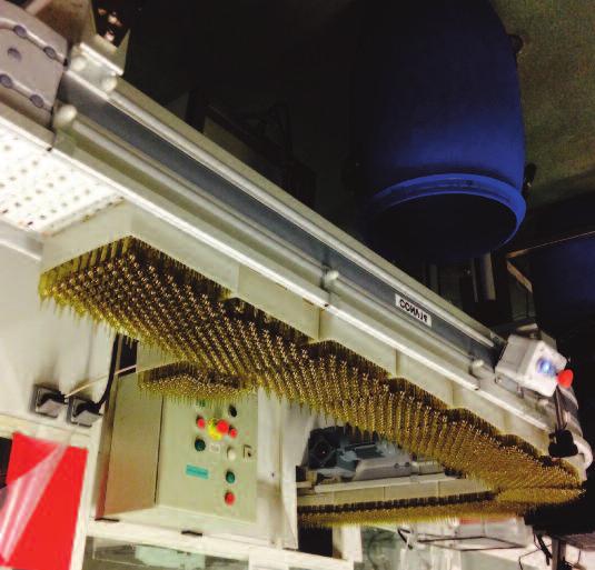
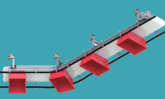
66 Plastic chains, pitch 38.1 mm Standard chain, minimum curve radius 400 mm Thicknesses: slat 4 mm, inserts +2 mm sens de marche Width width L Acetal, lubricated* LF880TAB... Acetal, black antistatic AS880TAB... Acetal white D880TAB... acetal, lubricated with anti-slip inserts HFL880TAB , K250...K250...K250...K TB 82, K325...K325...K325...K TB 114, K450...K450...K450...K , K750...K750...K750...K750 Curved chain, minimum curve radius 200 mm Necessary for modules with curves of 200 mm radius. Thicknesses: slat 880 TAB 4 mm, 878 BO 4,8 mm; inserts +2 mm Pieds-Legs-Ständer Guides-Führungen CAB, CAB-SB Chain width Lubricated acetal LF880TAB , K250 R...K250 R...K250 R...K250 R 2 & LF879-82, K325 R...K325 R...K325 R...K325 R...K325 R...K325 R...K325 2TB K325 R GRIP 3 & 114, K450 R...K450 R...K450 R...K450 R...K450 R...K450 3TB 1 63, K250...K250...K250...K TB 82, K325...K325...K325...K TB 114, K450...K450...K450...K , K750...K750...K750...K750 Other materials to order (chemical, abrasion or temperature resistant). Chains with anti-slip inserts: consult us. ROBUR Chain width L Black antistatic acetal AS880TAB... sens de marche Acetal, white D880TAB... Lubricated acetal LF Acetal, white D 879 SC Safety finger acetal, antistatic black AS Lubricated acetal LF878BO... Acetal, white D Lubricated acetal Straight chain (Only to order for straight conveyors) Requires special sprockets and bottom guide profiles. Thicknesses: slat 4 mm; inserts +2 mm Lubricated acetal + anti-slip ins. HFL880TAB... Lubricated acetal + anti-slip ins. HFL878BO... Acetal, lubricated with anti-slip inserts HFL820...


67 Metal chains, pitch 38.1mm and adaptations Curved chain Option requiring special gears. Slat thickness 3.15 mm. Figure 1 Figure 2 2-2TB 82, K325...K K325R...K325R TB 114, K450...K , K750...K , K250...K TB 82, K325...K TB 114, K450...K , K750...K750 ROBUR Chain width L Chain width L Stainless steel SS881TAB... Straight chain This chain is only available to order for straight conveyors. Requires special sprockets and bottom guide profiles. Slat thickness 3.15 mm. Stainless steel SS Steel S881TAB Steel S Average minimum radius of curves on slip rails Plastic lug chain Addition of machined lugs to order, screwed through the slats of different chains. Note: The safety of persons must be considered right from the design stage of conveyors fitted with lugs, because of the inevitable danger points between lugs and legs, lugs and lateral guides, lugs and housings, etc... Figure Pieds-Legs-Ständer Guides-Führungen CAB, CAB-SB


68 low height Structures, Straight modules The " low height" range offers 3 different widths (see below). Chains: standard curved plastic, pitch 38.1 mm, to order straight metal, or straight plastic chains. Anodized aluminium profiles. The usual mean radius of curvature is 200 mm (on rotating plates) and 500 mm (on clip rails). Linking fish plates included in the modules. Fasteners M8 stainless steel. The side groove can be closed by a flexible black cover reference 15 CN. Accessories: Side bracket clamps or leg clamps clip over this groove cover. Range 1 2 Low height 3 Low height Monobloc straight modules: Production to order of any length x from 200 to 3000 mm Ref. R1 D...x R2TB D...x R3TB D...x Beam R1 PS R2TB PS R3TB PS H 63,5 84 mm (Biflex chain) or 87 mm (straight chain) 82,5 114,3 Pieds-Legs-Ständer Guides-Führungen CAB, CAB-SB 70 Open straight modules: Production to order of any length x from 200 to 3000 mm 5 Not applicable Ref. R2TB Dx OPEN R3TB Dx OPEN Side R2TB FS R3TB FS ROBUR 68 H 86 H H

 70 86 118 Lc (chain) 63.5 82.5 114.")
69 low height End modules End modules: Their construction is based on a moulded aluminium yoke and uses of standard bearings. End modules include the corresponding housings. Gear motors and their connection flanges are sold separately (casings in black polyethylene th. 10 mm or to order, 30/10 stainless steel); 9-tooth sprocket for plastic chains or 18 tooth for metal chains with primitive Ø mm Drive modules Version below: shaft on the right. 164 L1 Symmetrical version, not shown = shaft on the left standard: 500 min.: Lt Range 1 2 Low height 3 Low height Lt (beam) Lc (chain) L1 (housing included) References of drive modules above (shaft Ø20) shaft on the right R1 MD20 R2TB MD20 R3TB MD20 shaft on the left R1 MG20 R2TB MG20 R3TB MG20 References of idler modules (below) R1 R R2TB R R3TB R ROBUR Idler modules These modules are fixed to clear beams in the bottom part over a length of 126 mm L1 The reintroduction of the chain return strand is by a system of shoes integral to the side housings Pieds-Legs-Ständer Guides-Führungen CAB, CAB-SB


70 low height Curves on slip rails Horizontal curves on slip rails: Each module is supplied with one connecting fish plate. The black groove cover profile, the required length of slip profile to be clipped on during assembly, and the chain should be ordered separately. Recommendations for use: It is generally recommended not to exceed a total of 180 of curves on slip rails per conveyor (horizontal curves and vertical curves). angle a Rm The usual radius is 500 mm on the chain centre line Pieds-Legs-Ständer Guides-Führungen CAB, CAB-SB Material: Black HDPE Angle a 1 2 Low height 3 Low height ROBUR 15 R1 C500/15 R2TB C500/15 R3TB C500/15 30 R1 C500/30 R2TB C500/30 R3TB C500/30 45 R1 C500/45 R2TB C500/45 R3TB C500/45 60 R1 C500/60 R2TB C500/60 R3TB C500/60 90 R1 C500/90 R2TB C500/90 R3TB C500/ R1 C500/135 R2TB C500/135 R3TB C500/ R1 C500/180 R2TB C500/180 R3TB C500/180 Vertical Curves: Recommendations for use: For angles 4, a bias connection of the modules provides a more economical solution (a special fish plate is required). Beyond 7, anti-slip inserts or lugs are generally necessary to avoid spontaneous slipping of the products conveyed. 5 R1 CV500/5 R2TB CV500/5 R3TB CV500/5 7 R1 CV500/7 R2TB CV500/7 R3TB CV500/7 x R1 CV500/x R2TB CV500/x R3TB CV500/x 70 The usual mean radius is 500 mm Angle a 1 2 Low height 3 Low height 100 a 100
 allow connection to adjacent modules.")
71 low height Curves with wheels Curve modules with wheels enable a reduction in tensile forces and a greater number of curves per conveyor. The straight end sections (100 or 110 mm) allow connection to adjacent modules. The connection of 2 of these modules together necessitates an intermediate straight module of a length of at least 200 mm. These modules require 880/881 Tab K...chains R (radius 200 mm), with which the whole conveyor must be fitted. Range R1 1 R2TB 2 Low height R3TB 3 Low height Conveyor width Straight sections R1 C200/45 R2TB C200/45 R3TB C200/45 90 R1 C200/90 R2TB C200/90 R3TB C200/ R1 C200/180 C200/45 R2TB C200/180 C200/45 R3TB C200/180 C200/45 90 x R1 C200/90 C200/x R2TB C200/90 C200/x R3TB C200/90 C200/x Plastic 180 chains R1 C200/180 4 R2TB C200/180 4 R3TB C200/180 4 Metal x chains R1 C200/x 5 R2TB 4 C200/x (*) R3TB 5C200/x Examples: 100 Rm Rm 200 ROBUR * Metal chains of are only available in 200 mm radius for R2TB. They require a bottom tray supplemented by a support disc Rm Pieds-Legs-Ständer Guides-Führungen CAB, CAB-SB


72 2 Low height Fish plates, slip profiles, gears Fish plates: Each module is supplied with its connecting fish plating. If the module is of the monobloc type, we use 2 half-fish plates. If it is an open type or a curve on slip rails, the fish plate is monobloc. Curves with wheels do not require fish plates. 1 2 Taille Low height Basse 3 Taille Low height Basse Monobloc fish plate between sides 5 Not non applicable 2 half-fish plates for beams Pieds-Legs-Ständer Guides-Führungen CAB, CAB-SB Top profile For straight or curved chain Bottom profile for curved chain Bottom profile for curved chain Mounting screw for slip profiles: FS ST M4.2x9.5 ROBUR Slip profiles: 1 2 Taille Low height Basse 3 Taille Low height Basse R1 PGR3 & R1 PGR16 R2TB PGHD1000 R3 PG R1 PG-CD R2 PG-CD R3 PG-CD 72 For plastic curved chain (880TAB) 9 tooth: N_ROBUR Gears: For straight plastic chain (820) 18 tooth: _ROBUR For metal chain (881TAB and 81x) 18 tooth: _ROBUR


73 standard height Structures & Straight modules The " standard height" range offers 3 different widths (see below). Chains: standard curved plastic, pitch 38.1 mm, to order straight metal, or straight plastic chains. Anodized aluminium profiles. The usual mean radius of curvature is 200 mm (on rotating plates) and 500 mm (on clip rails). Linking fish plates included in the modules. Fasteners M8 stainless steel. The side groove can be closed by a flexible black cover reference 15 CN. Accessories: Side bracket clamps or leg clamps clip over this groove cover. Range Monobloc straight modules: Production to order of any length x from 200 to 3000 mm Ref. R2 D...x-MONO R3 D..x.-MONO Beam R2 PS R3 PS H 145 mm (Biflex chain) or 148 mm (straight chain) 82,5 114,3 H H ROBUR H H H 5 non Not applicable Open straight modules: Production to order of any length x from 200 to 3000 mm Ref R2 D...x R3 D...x R4 D...x Side R2 FS R3 FS R4 FS ,5 Pieds-Legs-Ständer Guides-Führungen CAB, CAB-SB
.")
 86 118 196 Lc (chain) 82.5 114.3 190.")
74 standard: 500 min.: mini: 280 Lt standard height End modules End modules: Their construction is based on a moulded aluminium yoke and uses of standard bearings. End modules include the corresponding housings. Gear motors and their connection flanges are sold separately (casings in black polyethylene th. 10 mm). 11-tooth sprocket for plastic chains with primitive Ø mm, 21 tooth sprocket for metal chains with primitive Ø mm Drive modules 130 With standard RxM housing... L1 212 Drive modules Option with roller housing Pieds-Legs-Ständer Guides-Führungen CAB, CAB-SB 150 ROBUR L Range Lt (beam) Lc (chain) L1 (housing included) References of drive modules with standard housing (shaft Ø20) shaft on the right R2 MD20 R3 MD20 R4 MD20 shaft on the left R2 MG20 R3 MG20 R4 MG20 References of idler modules with standard housing (below) R2 R R3 R R4 R Idler modules with standard RxR housing Version above: shaft on the right. Symmetrical versions, not shown = shaft on the left 74 Idler modules Option with roller housing


.")
75 standard height Curves on slip rails Horizontal curves on slip rails: Each module is supplied with one connecting fish plate. The black groove cover profile, the required length of slip profile to be clipped on during assembly, and the chain should be ordered separately. Recommendations for use: It is generally recommended not to exceed a total of 180 of curves on slip rails per conveyor (horizontal curves and vertical curves). angle a Rm 500 2: Curved sides + profile R2PG... 3 & 4: Curved sides + machined soles Angle a ROBUR 15 R2 C500/15 R3 C500/15 R4 C500/15 30 R2 C500/30 R3 C500/30 R4 C500/30 45 R2 C500/45 R3 C500/45 R4 C500/45 60 R2 C500/60 R3 C500/60 R4 C500/60 90 R2 C500/90 R3 C500/90 R4 C500/ R2 C500/135 R3 C500/135 R4 C500/ R2 C500/180 R3 C500/180 R4 C500/180 Vertical curve modules: Material: Black HDPE. Recommendations for use: For angles 4, a bias connection of the modules provides a more economical solution (a special fish plate is required). Beyond 7, anti-slip inserts or lugs are generally necessary to avoid spontaneous slipping of the products conveyed. Angle a R2 CV500/5 R3 CV500/5 R4 CV500/5 7 R2 CV500/7 R3 CV500/7 R4 CV500/7 x R2 CV500/x R3 CV500/x R4 CV500/x a 100 Pieds-Legs-Ständer Guides-Führungen CAB, CAB-SB
 allow connection to adjacent modules.")
, with which the whole conveyor must be fitted.")
 5 * Metal chains are only available with a radius of 200 mm for R2.")
76 2 & 3 Curves with wheels Curve modules with wheels enable a reduction in tensile forces and a greater number of curves per conveyor. The straight end sections (250 mm) allow connection to adjacent modules. 2 of these modules can be connected together without a straight module between them. These modules require 880/881 Tab K...chains R (radius 200 mm), with which the whole conveyor must be fitted. Range Straight sections x Plastic chains Metal chains R2 C200/45 R3 C200/45 R2 C200/90 R3 C200/90 R2 C200/180 R3 C200/180 R2 C200/x R3 C200/x (*) 5 * Metal chains are only available with a radius of 200 mm for R2. They require a bottom tray supplemented by a support disc. R2C200/180 R3C200/90 Pieds-Legs-Ständer Guides-Führungen CAB, CAB-SB Rm 200 ROBUR Rm


 11 tooth:")

77 standard height, Fish plates, Slip profiles, Sprockets Fish plates: Each module is supplied with its connecting fish plating. If the module is of the monobloc type, we use 2 half-fish plates. If it is an open type or a curve on slip rails, the fish plate is monobloc. Curves with wheels do not require fish plates Monobloc fish plate between sides 2 half-fish plates for beams 5 non Not applicable Top profile For straight or curved chain Bottom profile for curved chain Bottom profile for curved chain ROBUR For plastic curved chain (880TAB) 11 tooth: N_ROBUR Slip profiles: R2 PGHD1000 R3 PG R4 PG R2 PG-CD R3 PG-CD R4 PG-CD Sprockets: Sprockets, item 1 For straight plastic chain (820) 21 tooth: N-ROBUR 77 For metal chain (881TAB and 81x) 21 tooth: _ROBUR Pieds-Legs-Ständer Guides-Führungen CAB, CAB-SB


78 conveyors Minimum dimensions with 2 curves of 90 in the same or the opposite direction Y1 X1 X1 X1 Z1 Pieds-Legs-Ständer Guides-Führungen CAB, CAB-SB Z1 Conveyor reference with plastic chain ROBUR Y1 with metal chain Chain width Conveyor width , min. mini TB min. mini , min. mini min. mini TB min. mini , min. mini min. mini min. mini , min. mini The dimensions indicated cover standard curved modules with minimum length drive modules. Consult our Design Office to validate your installations. 78 Mean radius of curves Y1 X1 min Y1 min Z1 min


79 Aluminium modular conveyors CAB Ball conveyors CAB-SB Straight conveyors Pieds-Legs-Ständer Guides-Führungen CAB, CAB-SB CAB, CAB-SB 79


 are common to all our ranges and are fixed in the 2 side grooves.")
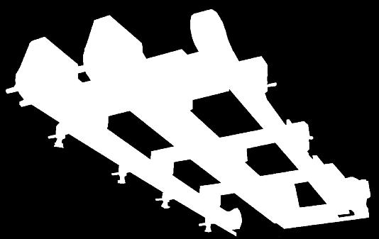
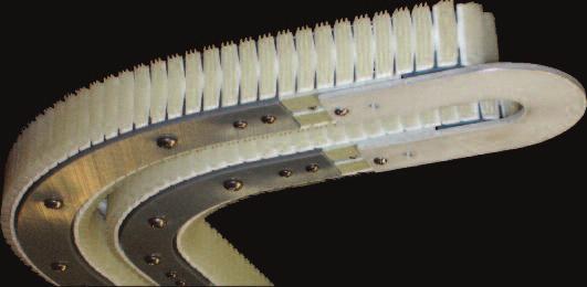
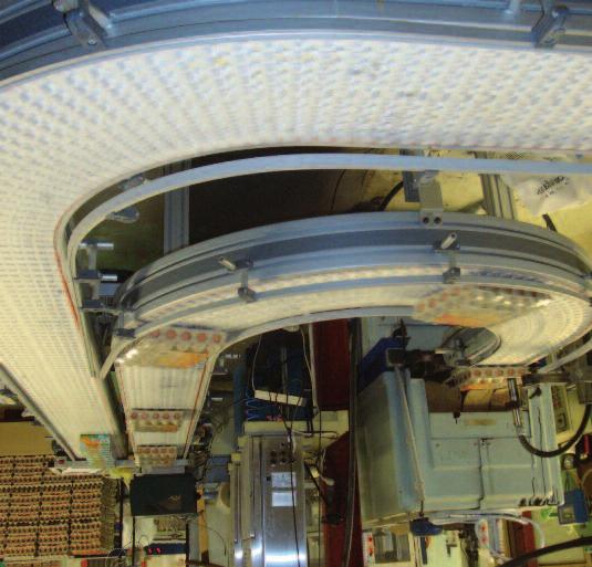
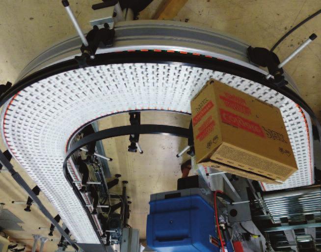
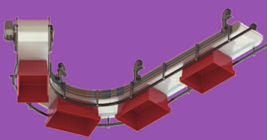
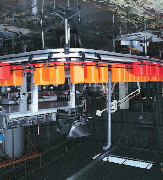
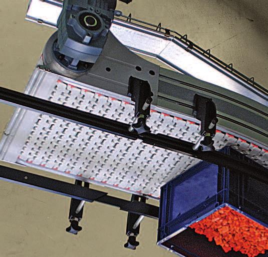
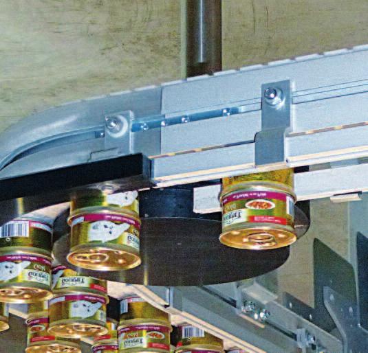
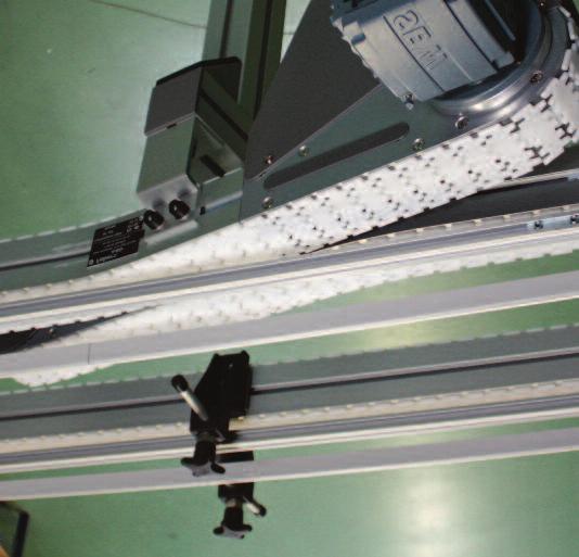
80 CAB: Ball conveyors Structure Tough and silent for conveying and handling boxes & hard base bulky products. CAB is available in several widths: see table on the next page) Modularity. Tough structure, Silent. Optimum staff safety. Quick and easy maintenance. Multidirectional ball belt, pitch 25.4 Very strong: The QNB BALL Handling functions achievable thanks to or several conveyors integrated in the structure (as from the CAB 15 QNB version): Referencing on a fixed edge, 90 transfer Ejection of non-compliant products, Creation of a pitch between the products, reduction of the gap between products, stoppage of the product on the running conveyor, reversing the direction of feed of the product Product rotation It is possible to integrate several functions in a same feeder, depending on the length available. Pieds-Legs-Ständer Guides-Führungen CAB, CAB-SB Sectional view Many accessories (guides, supports, etc.) are common to all our ranges and are fixed in the 2 side grooves. Lower groove for attaching the legs (HM6 screws) CAB 239 W A 80 Slip profiles: CAB PG white PEHD F2PG white HDPE Groove cover FACS 25 optional
 CAB 9 M-TTB CAB 9 SNB M2R 5 254 mm 267 mm 1 5 5 5 CAB 10 RTB 304,8 304.8 mm 318 318 mm CAB 12 QNB (*) CAB 12 M-TTB CAB 12SNB M2R CAB 12 RTB 355,6 355.")


 possible for CAB 15 QNB and others M-TTB SNB M2 Roll Pitch of 12.7 mm with rollers Pitch of 25.")
81 Belt width Conveyor width (A) 152, mm 165 mm CAB 6 QNB (*) CAB 6 M-TTB CAB 6 SNB M2R CAB 6 RTB 203, mm mm CAB 8 RTB 228, mm mm CAB 9 QNB (*) CAB 9 M-TTB CAB 9 SNB M2R mm 267 mm CAB 10 RTB 304, mm mm CAB 12 QNB (*) CAB 12 M-TTB CAB 12SNB M2R CAB 12 RTB 355, mm 369 mm CAB 14 RTB 381 mm 394 mm CAB 15 QNB CAB 15 M-TTB CAB 15 SNB M2R 5 406, mm 420 mm CAB 16 RTB 457, mm 470 mm 2 CAB 18 QNB CAB 18 M-TTB CAB 18 SNB M2R CAB 18 RTB 508 mm 521 mm CAB 20 RTB 533, mm 546 mm CAB: Ball conveyors and roller variants Dimensions, straight modules Number of support profiles QNB (ball) belt (previous page) M-TTB belt figure 1 SNB M2 Roll belt figure 1 RTB belt figures 3 & 4 CAB 21 QNB CAB 21 M-TTB CAB 21 SNB M2R 5 558, mm 572 mm CAB 22 RTB 609, mm 623 mm CAB 24 QNB CAB 24 M-TTB CAB 24 SNB M2R CAB 24 RTB The belt widths and the dimension A are for the QNB belt. They vary slightly compared with the other internal band conveyor belts (*) possible for CAB 15 QNB and others M-TTB SNB M2 Roll Pitch of 12.7 mm with rollers Pitch of 25.4 mm with rollers for accumulation for accumulation Versions of the CAB under development RTB M1 Pitch of 50.8 mm A belt with small swivellable rollers RTB M2 RTB M2 Rubber (PU coated) Pitch of 50.8 mm, belt with swivellable rollers POM belt, PA66 balls; (other materials to order) The RTB-M2 belt allows the products to be centred on the conveyor. Straight modules CAB D... (standard length 3m, others to order) CAB FACS-20x140A connection fish plates not included 81 Pieds-Legs-Ständer Guides-Führungen CAB, CAB-SB


 Pieds-Legs-Ständer Guides-Führungen CAB,")
 18 tooth drive gears, pitch 25.")
 Not compatible with anti-slip lugs or")
82 Vertical curves and idler and direct drive modules, end transfers Vertical curved modules mean radius 500 mm (angles to order) 80 a CAB CV500 B a CAB CV500 H Standard & knife edge idler modules ØP = 68.7 mm) Pieds-Legs-Ständer Guides-Führungen CAB, CAB-SB Drive modules Modules with slack strand (Ø20 or Ø30 shaft) 18 tooth drive gears, pitch 25.4 i.e. ØP = mm End transfers CAB (ØP = mm) Not compatible with anti-slip lugs or inserts 210 CAB MDG CAB MDD CAB TG1 210 CAB TG2


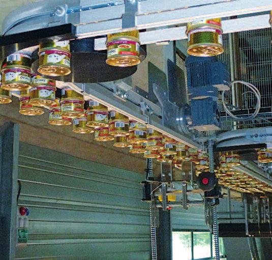
83 CAB: Functions with the QNB ball belt Lateral movement Applications: Referencing on a fixed edge 90 transfer Ejection of non-compliant products Rotational movements With two belt conveyors with different speeds placed in parallel in the structure Variation in the conveying spee Applications: Creation of a pitch between products Reduction of the gap between products Stoppage of the product on the running conveyor Reversal of the direction of feed of the product CAB 83 With pivot stop For these functions, our conveyors do not require compressed air. Energy saving Reduction of the installation costs Time saving in the fitting in the machine or the packaging line Possibility of including multiple functions on a single conveyor Pieds-Legs-Ständer Guides-Führungen CAB, CAB-SB Before any order, tests should be carried out in our workshops to validate the proposed functions.
 A Groove cover FACS 25 optional Conveyor")

84 CAB-SB Structure Sectional view Many accessories (guides, supports, etc.) are common to all our ranges and are fixed in the 2 side grooves. W approximately 39, depending on the belt Slip profiles: CAB PG white PEHD F2PG white HDPE Lower groove for attaching the legs (HM6 screws) A Groove cover FACS 25 optional Conveyor reference Belt width Conveyor width (A) Number of support profiles QNB, JCB, SNB M2, M-TTB and M-QNB belts Pieds-Legs-Ständer Guides-Führungen CAB CAB-SB, CAB-SB 6 152,4 mm 165 mm 4 CAB-SB 9 228,6 mm 242 mm 4 1 CAB-SB ,8 mm 318 mm 4 CAB-SB mm 394 mm 4 CAB-SB ,2 mm 470 mm 2 4 CAB-SB ,4 mm 546 mm 4 3 CAB-SB ,6 mm 623 mm 4 The belt widths and the dimension A vary slightly depending on the belt. CAB-SB 84


85 CAB-SB Tough and silent for conveying boxes & bulky products. CAB-SB is available in several widths: 165 mm, 242 mm, 318 mm, 394 mm, 470 mm, 546 mm, 623 mm (beyond this to order) Modularity, Tough structure, Silent, Optimum staff safety, 3 types of belt available with a pitch of 25.4, Quick and easy maintenance, Conveyor length 570 mm. CAB-SB: this is a range of conveyors equipped with smooth, openwork or closed belts QNB C closed belt CAB-SB Versions of CAB-SB available: belt with a pitch of 25.4 mm JCB Y closed belt 85 SNB M2 20% Versions of CAB-SB under development: belt with a pitch of 12.7 mm M-QNB closed belt POM belt (other materials to order) Pieds-Legs-Ständer Guides-Führungen CAB CAB-SB, M-TTB openwork belt SNB M2 34% openwork belt

86 CAB, CAB-SB Guides-Führungen Pieds-Legs-Ständer Guides-Führungen 86


87 Guides for conveyors CAB, CAB-SB Guides-Führungen Pieds-Legs-Ständer Guides-Führungen 87
 20,25 20.25 FL2 V N 3 m Machined 20 17,5 17.")

 PTFE (Teflon ), length 1200 mm Black High Density Polyethylene Extruded")
88 Lateral guide profiles with metal frames Profiles FL1 H Contents and profile colours N T V Observations Packaging 3 m Machined Frame: C2010X or C2010Z Frame and clamp (if compatible) idem + EL60 bracket 30 idem + EL92 bracket ,1 40, , Frame AC2A8 (aluminium) 20, FL2 V N 3 m Machined 20 17, X incompatible X incompatible 29 FL5 20 NE N X FL5U H30 30 NE N V 3 m Extruded Machined H X incompatible X incompatible ,5 FL5UH40 40 V 3 m Machined FL5S 20 N V 3 m Machined ,5 26, FL5S H30 30 N V 3 m FL8 V Machined Extruded 20 H H X incompatible X incompatible 31, CAB, CAB-SB Guides-Führungen Pieds-Legs-Ständer Guides-Führungen B N R V NA X T NE Materials of plastic profiles Natural High Density Polyethylene Black High Density Polyethylene Red High Density Polyethylene Green High Density Polyethylene Black Anti-Static High Density Polyethylene OV Protect 7 blue (better slipping) PTFE (Teflon ), length 1200 mm Black High Density Polyethylene Extruded Other materials and colours to order Plastic clamps for C2010 above 60 EL60 (Machined acetal) 25 x 8 59 EL92 (Moulded PA6) , ,5 1.5 C2010Z (zinc plated steel) C2010X (stainless steel) Weight in kg/m: 0.49 Fish plate FBCS 13x50 Groove cover CR8N2 88 Metal frames above 21, ,5 20, AC2A8 (Extruded black anodized aluminium) Weight in kg/m: 0.51 H M8 standard fastenings Accessories for AC2A8 above Possibility of brush guides Height 5 to 120 mm 20,25


. Lateral guidance profiles for aluminium frame AT30 Profile Ref.")


89 Lateral guide profiles with metal frames Lateral guide profiles FD7... for metal strip Profile Ref. B H b1 b2 h1 h2 Mild steel strip not supplied Dimensions FD , x 3 FD , x 4 FD , x 8 FD , x 6 FD , x 5 FD , x 5 FD , x 3 FD , x 5 FD , x 6 FD , x 6 b1 H h2 h1 FD7-x b2 B B Materials and colours of the FD7 profiles B N R V NA Other materials and colours to order Example of installation: with threaded pin (to be ordered separately) and steel or stainless steel strip (not supplied). Lateral guidance profiles for aluminium frame AT30 Profile Ref. B H b1 b2 h1 h2 FD 7-1A ,5 30,5 5,3 8,5 FD 7-2A ,5 30,5 5,3 8,5 FD 7-4A ,5 30,5 5,3 8,5 Materials and colours of the FD7-1 profiles Reference RI12 TI12 B N R V NA Other materials and colours to order Stainless steel bar and tube Ø12 Packaging: 3m bar Fish plate FBCS-13x50 Groove cover CR8N2 Stainless steel bar Ø12 Stainless steel tube Ø12 Application Straight or curved lateral guide Straight lateral guide Armature, black anodised aluminium 89 AT30 FD7-xA AT30 HM8 standard fastenings Plastic part FGPR FD100 in black POM for guides FD7-1A... in curves CAB, CAB-SB Guides-Führungen Pieds-Legs-Ständer Guides-Führungen

")


90 Lateral guides and intermediate ball and roller guides (aluminium structure) E.g.: FGLB 1 Lateral ball guide, single height E.g.: FGCR 2 Central roller guide, double height Balls and rollers, pitch 12 mm, Unit length 3m mounting by M8 screws and fish plates: FBCS 13x50 Groove cover CR8G2 Bends to order FGLB 1 FGLR 1 FGCB 1 FGCR 1 CAB, CAB-SB FGLB 2 FGLR 2 FGCB 2 FGCR 2 Guides-Führungen Pieds-Legs-Ständer Guides-Führungen H Reference figure FGEC L1 1 FGEC L1A 2 48 FGEC L Grey PE ends, stainless steel fastenings H Can be fitted on FGLB1 FGLR1 FGLB2 FGLR Reference H H FGEC C1 62 FGEC C1 62 FGEC C2 107, Can be fitted on FGCB1 FGCR1 FGCB2 FGCR2
")


91 Lateral formable ball and roller guides* (stainless steel frame) Lateral ball guide, single height FGLB 1C Lateral roller guide, single height FGLR 1C 12.5 ø ø Lateral ball guide, double height FGLB 2C 375 Lateral roller guide, double height FGLR 2C 12.5 ø ø Examples of use CAB, CAB-SB * minimum radii: inside 350 mm, outside 500mm 91 Stainless steel frame for the guides above FGRRX 3x40x8 can also be used alone as a lateral guide. Groove for HM8 head, Packaging: bar of 3m 40 Guides-Führungen Pieds-Legs-Ständer Guides-Führungen 8
 FGRR 3x20x10T (steel) Profile FGRR 3x20x10 F Natural anodised")

 CAB, CAB-SB Flexible profile FGRR 3x20x10P for adjustable curves")


92 Profile 20x10 Packaging: 3m bar It can be used alone (not covered with protection profiles below) FGRR 3x20x10 (natural anodised aluminium) FGRR 3x20x10T (steel) Profile FGRR 3x20x10 F Natural anodised aluminium Packaging: bar of 3m It can be used alone (not covered with protection profiles below) Lateral guide profiles Profile FGRR 3x20x10 B Natural anodised aluminium Packaging: bar of 3m It can be used alone (not covered with protection profiles below) End plug FGEC 10x20 Junction FGRJ 10x20 Grey plastic ends (Machined HDPE or moulded nylon) CAB, CAB-SB Flexible profile FGRR 3x20x10P for adjustable curves Grey machined PE in bars of 3m Mounting of these profiles by clamps or FGRA or FGRB brackets Guides-Führungen Pieds-Legs-Ständer Guides-Führungen Profile FGRR 3x20x12 Natural anodised aluminium Packaging: bar of 3m Used alone or covered with protection profiles FGRT... below. The rear groove can receive the cover CR8G2 End plug: FGEC 12x20 Fish plate: FBCS 13x50 Sliding gib FGRR FG25 We recommend placing at least a set of brackets every meter on the straight lengths, and 2 or 3 per curve. For the transfer of heavy products, or 20 x 10 profiles, the intervals can be reduced Mounting of this profile by standard HM8 screws


93 Lateral guide profiles Profile FGRRF 3x20x15 Natural anodised aluminium Packaging: 3m bar Used alone covered with protection profiles below Grey plastic ends (Machined HDPE or moulded nylon) Flexible profile FGRR 3x20x15P for adjustable curves Grey machined PE in bars of 3m. End FGEC 15x20 Junction FGRJ 15x20 Sloping end FGEC 30D Mounting of these profiles by clamps or FGRA or FGRB brackets Protection profiles in bars of 3m. For FGRR-3x20x12 & FGRR-F-3x20x15 profiles; they prevent wear of the rail and direct contact of the products with the aluminium. FGRT 3x23 FGRT 3x23A FGRT 3x33 FGRT 3x33A material Grey HDPE White anti-static HDPE material Grey HDPE Grey anti-static HDPE H 23 H 33 FGRT 3x50 Grey HDPE 50 H CAB, CAB-SB Colourless anodized aluminium fish plates, for joining FGRRF-3x20x15, FGRR 3x20x15P, FGRR 3x20x10, FGRR 3x20x10B, FGRR 3x20x10F, FGRR 3x20x10P and FGRR 3x20x10T x Fish plate Including grub screws. Profile also available by the meter. X FGRC FGRC Internal fish plate FBCS 13x50 for joining FGRR 3x20x12 AT30 AC2A8 93 Flocked lateral guides: Production to order Acetal flocked POM Profiles Guides-Führungen Pieds-Legs-Ständer Guides-Führungen

94 Guide holder and brackets Single vertical guide holder Material: PA6 30 Double vertical guide holder Material: PA6 30 Ø18 A B Ø18 A B Single guide Reference A B FGRL 18x110C Zinc FGRL 18x160C ØM5 fastenings plated steel Double guide Reference A B FGRC 18x110C Zinc FGRC 18x160C ØM5 fastenings plated steel SGRL 18x110C Stainless SGRL 18x160C steel SGRC 18x110C Stainless SGRC 18x160C steel CAB, CAB-SB Plastic guide holder pin Guide holder bracket Enables vertical adjustment of the Ø18 pin of the guide holder by tightening with an M5 screw provided. Material: PA6 Ø18 37 Guides-Führungen Pieds-Legs-Ständer Guides-Führungen Reference A FGRK 18x40A 40 FGRK 18x60A 60 FGRK 18x80A 80 FGRK 18x130A 130 A ØM5 fastenings Zinc plated steel SGRK 18x80A 80 Stainless SGRK 18x130A 130 steel 94 Ø18 A Reference A B ØM5 fastenings FGRL 18x110CA Zinc plated FGRL 18x160CA steel SGRL 18x110CA Stainless SGRL 18x160CA steel B


 FGGR 18xL (L=length to order request) End")
, enables the creation of guide holders of all")
 Stainless steel tube ø19 cut to length: SGGR 19x150 (L.")
 Other lengths to order End plug SGEC 19 Junction SGRJ 3x19 for tube above")
95 Guide holder clamp in PA6 between - vertical tube Ø18 - lateral guide FGRR-3x20 or tube ø18 FGGR or SGRR below Height and width adjustable brackets with assembly sheave Aluminium bracket FGRB 22x63 Reference of the clamp FGRS 18 SGRS 18 Fastenings Zinc plated steel Stainless steel Guide holder clamp in PA6 between - vertical profile FGRRF 3x20x15 - lateral guide FGRR-3x20x10 or FGGRF 3x20x15 Reference of the clamp FGRS 15x20 L Fastenings Zinc plated steel Aluminium tube Ø 18/13: FGGR 3x18 (L. 3m can also be used as a lateral guide) FGGR 18xL (L=length to order request) End plug FGEC 18 Junction FGRJ 18x18 For tube above Guide holder FGRK 18CE Used with the tube ø18 FGGR 3x18 (aluminium), enables the creation of guide holders of all sizes. Material: PA6 95 Stainless steel tube Ø 19: SGGR 3x19 (L. 3m, lateral guide) Stainless steel tube ø19 cut to length: SGGR 19x150 (L. 150 mm) SGGR 19x200 (L. 200 mm) Other lengths to order End plug SGEC 19 Junction SGRJ 3x19 for tube above Aluminium brackets FGRB 22x63 Usable for example as a guide bracket under a slat CAB, CAB-SB Guides-Führungen Pieds-Legs-Ständer Guides-Führungen


 Zinc plated steel 1 FGRF")


96 xgrf brackets & spacers Moulded guide holders Clamping system by means of an M6 screw Bracket attachment to the aluminium profile, by Ø M8 mm nuts and bolts sold separately. Material: PA6 Reference Material Fastenings Figure FGRF 42x18V plastic (PA6) Zinc plated steel 1 FGRF 42x18VH zinc Zinc plated steel 2 SGRF 42x18V plastic (PA6) Stainless steel 1 Ø Spacer Material: PA6 CAB, CAB-SB Reference E FGRD 6A 6 FGRD 18A 18 E Guides-Führungen Pieds-Legs-Ständer Guides-Führungen Aluminium profile FGRN 3U for making a spacer. 96 Plastic plug FGRD 3D Th.=3mm For profile below


97 Assembly sheaves and corner connectors Assembly sheave Corner connector Ø A E Ø B Reference E Ø A Ø B Fastenings EO 12x Stainless steel FGRB 18x Zinc FGRB 18x plated FGRB 20x steel SGRB 18x SGRB 18x Stainless SGRB 20x steel EO 20x Ø A Ø B Reference Ø A Ø B Fastenings FGRX 18x Zinc FGRX 18x plated FGRX 20x steel SGRX 18x Stainless SGRX 18x steel SGRX 20x Assembly sheave 22 Corner connector FGRX 15x20 for FGRRF 3x20x15; zinc plated steel fastenings CAB, CAB-SB Ø A 20 x 15 Reference Ø A Fastenings FGRB 18X20T 18 Zinc plated FGRB 20X20T 20 steel SGRB 18X20T 18 Stainless steel x 15 Guides-Führungen Pieds-Legs-Ständer Guides-Führungen


98 Width adjustable brackets F/S-GRB Height adjustable brackets FGRF Lateral guide bracket or bar Ø 18 or Ø 20 Lateral guide bracket FGRB 40x15x20 for FGRRF 3x20x15 CAB, CAB-SB Reference for bar Ø Fastenings FGRB 40x18 18 Zinc plated FGRB 40x20 20 steel SGRB 40x18 18 SGRB 40x20 20 Spacer FGRD 6B thickness 6.3mm for brackets FGRB * the groove provides anti-rotation for the brackets of guides xgrb 40 41* Stainless steel Guides-Führungen Pieds-Legs-Ständer Guides-Führungen Moulded guide bracket Clamping system by means of an M6 screw. To fix the bracket to the aluminium profile, use ØM8 mm nuts and bolts sold separately. Material: PA6 W ØA Reference for bar ØA W Y Fastenings FGRF 40x Zinc plated FGRF 40x steel Y 98 Spacer FGRD 30B for FGRF 40x18 thickness 30mm 2 holes Ø 9 centre distance 52 Material: PA


 for bar Ø 18 Reference A B FGRB")


99 Guide for FGRF moulded brackets (1, 2 or 4 levels) 2 level lateral guide bracket for bar Ø 18 Reference FGRF A35 SGRF A35 Fastenings Zinc plated steel Stainless steel 4 level lateral guide bracket for bar Ø 18 Reference FGRF A110 SGRF A110 Fastenings Zinc plated steel Stainless steel 0 N2 N1 N4 N3 N2 0 N1 Pin heights above the chain Pin heights above the chain N1 N2 FK and et FS FM-FC-FL F Single level lateral guide bracket (plastic) for bar Ø 18 Reference A B FGRB 11x30C FGRB 16x42C FGRB 16x54C FGRB 40x42C N1 N2 N3 N4 FK and et FS FM-FC-FL F Tightening knob FGAR 6x20 for lateral guide brackets...grf-a... Plug FGRF DP for lateral guide brackets...grf-a CAB, CAB-SB Guides-Führungen Pieds-Legs-Ständer Guides-Führungen 20


 103 End-CCD12 For pins Ø12 11 Combined pins and clamps Guide:")


100 Pins Ø12 for brackets GH5 Combined pins and clamps Guide holder clamps Stainless steel pin AF703CC Ø 12 threaded M Ø 12 pins threaded M8 Reference Material Fig AF12/8 120CC Aluminium 1 AF720CC Stainless steel Ø Aluminium pin AFPOCC Ø 12 with swivel plate (80x25x8 + 2 holes Ø8.5) 103 End-CCD12 For pins Ø12 11 Combined pins and clamps Guide: Reference Pin Ø L Materials Figure bar Ø AF710CC S/s pin, PA clamp 1 AF712CC SGRK 12x80A Pin and PA clamp, 2 SGRK 12x130A s/s fastenings 1 2 CAB, CAB-SB L L Guides-Führungen Pieds-Legs-Ständer Guides-Führungen Guide holder clamp FGRC 20 also used to fix a cell to the 20x10 or 20x15 profile hole Ø 8.5 Material: Aluminium Guide holder clamp FGRC 20A for 20x10 or 20x15 profiles, hole for M8 screw F/45 Material: Aluminium 100


101 Product guide Adjustable in height and width Moulded brackets GH5, plastic clamps Lateral guide brackets GH5... for bar Ø 12 GH5 5 GH5 1PM GH5 1B GH5 2 GH5 3 with swivel head GH5 4 25, , Plastic clamps A 25 x 8 A 25 x 8 A 66 Reference EL 30 EL 60 EL 92 EL 72 PSR CC A material machined POM moulded PA6 moulded PA6 moulded PA6 + s/s bar Ø12 for frames C Spacer FGRD 6B th. 6mm for brackets GH5. This shim also performs the anti-rotation function for the bracket with and conveyors frames C S/s bar Ø A S/s bar Ø12 Thrust collars for lateral guiding or motor shafts or conveyor idlers A Référence BAGUE D ARRET D12 BAGUE D ARRET D20 BAGUE D ARRET D25 BAGUE D ARRET D30 BAGUE D ARRET D40 BAGUE D ARRET SQ40 A Ø12 Ø20 Ø25 Ø30 Ø40 40x40 CAB, CAB-SB Guides-Führungen Pieds-Legs-Ständer Guides-Führungen


102 Accessories for and Cobral conveyors Attachment in the side groove The connection with these conveyors is by attachment in the dovetail groove, by an aluminium clamp, a moulded plastic clamp or a dovetail nut. Anodized aluminium clamps thickness 25.4 These clamps allow - many possibilities of machining (drilling, etc.) - larger lateral forces. 1 2 A A The clamps can be clipped over the groove cover. Stainless steel Ø M8 screws. Tapped holes Ø M8. CAB, CAB-SB Reference A Figure R1 SL32-SL40 40 R1 SL32-SL R2 SL32-SL40 40 R2 SL32-SL Plastic clamps, Clamps can be clipped over the groove cover. Stainless steel fastenings Ø M8 moulded for lateral guide brackets. Reference A Figure R1 SL1/21.5M 25 3 R2 SL1/17M 40 4 machined from black acetal for the cell bracket, reflector bracket, etc... Reference H for /Cobral Figure R2 SL2-H65 65 low height 5 R2 SL2-H86 86 standard height Spacers R2 SLA... Spacer for R2SL1/17, figure 5 (E= 8, 13, 18, 20, 23, 28, 30, 33, 38, 40, 48) 3 4 A 5 A E 40 5 Ø 12 16,5 Ø M8 33 H Guides-Führungen Pieds-Legs-Ständer Guides-Führungen Nuts for dovetail for & Cobral conveyors These nuts allow accessories to be installed while saving space and cost. Central tapped hole. The fitting is generally done using an HC screw (headless) locked in the bottom of the dovetail. The assembly [screw + nut] then behaves like a stud. The installation of the groove covers is only possible between these nuts. Screws not included Reference material Ø thread use figure ECQA 40 M6 aluminium M6 ECQA 40 M8 aluminium M8 to thread 6 ECQA 40 M8 STEEL steel M8 ECQA/45 M6 aluminium M6 ECQA/45 M8 aluminium M8 to rotate 7 ECQA/45 M8 STEEL steel M


103 Guidance in quick dismantling products Rotobloc-GL system Our quick dismantling product guiding system guides your products over all the ranges of conveyors. Its Rotobloc locking system facilitates you changes in format and reduces your intervention time. Different colours of guides make it possible to match them with the other tools of the format of the line. The format parts are designed by our design office. Do not hesitate to consult us for all your needs. The locking / unlocking works by rotating fixing knobs. The ROTOBLOC system is also available for your format tools on your packaging machines. FLRG-xxx Ø = xxx Examples: Figure 1: ROTOBLOC curve outside guide Guide plate nested on the hub of the curve with wheels. Figure 2: 2 pairs of quick dismantling ROTOBLOC curved guides adapted to each side of a conveyor. Figure 3: 1 pair of quick dismantling ROTOBLOC with brackets for guides of other formats. Figure 4: curves with wheels equipped with 2 stage guides. Outside of curves with 1 or 2 level ROTOBLOC guides. 1 2 CAB, CAB-SB Guides-Führungen Pieds-Legs-Ständer Guides-Führungen


** 19 FASN M6 25")

 for")


 In stock, M8 threaded parts, ready to fit: FGDT 80 (L 80 mm) FGDT 100 (L100")
104 Fastenings Nuts (in zinc coated steel, packed in boxes of 50 pieces) Squares for T-shaped grooves Lozenge Rectangle Rocking Ball Clip-on with leaf spring With integral lock washer Ø M * of conveyors ** of conveyors (except F45) C for T-shaped grooves (except FBSB24... & KPS) for F45 CB3 for TC44, TC64, TC44x88, TC64, TC88 for F45 CB3 4 FASN M4 20 ECB 4 5 FASN M5 20 ECB 5 FCAN 5 F45AN M5B 6 8 FASN M6B (h 4)** 19 FASN M FASN M8 20 FASN M ØM FAHN M6 Ø M F45RN M6 (25x12x5) F45AN M6 (16x11) ECB 6 FCAN 6 F45AN M6B ECROU TWOLOCK M6 FAHN M8 ECB 8 FCAN 8 F45AN M8B ECROU TWOLOCK M8 C 22 CAB, CAB-SB Guides-Führungen Pieds-Legs-Ständer Guides-Führungen Square head and hammer head screws M8 (Packed in boxes of 50 or 100 pieces) for T-shaped grooves. The square head fits into the groove during assembly, the hammer head can be inserted without dismantling. Square head Hammer head Length Zinc plated steel Stainless steel 17 FATB 17 FATBX FASB 20 FATB 20 FATBX FATB 24 FATBX FASB 35 FATB 35 FATBX FATB 53 FATBX FATB 71 FATBX 71 ØM 8 ØM 8 Aluminium tube Ø20-17/flats FGDT: FGDT 3x20 (L. 3m) In stock, M8 threaded parts, ready to fit: FGDT 80 (L 80 mm) FGDT 100 (L100 mm) FGDT 150 (L150 mm) FGDT 200 (L200 mm) 104 CACHE VIS FHC FHC SCREW COVER Exists for FHcM6 colour grey or black FHcM8 colour grey or black CACHE-ECROU HM6 CACHE-ECROU HM8 colour grey or black Bouchon Plug FGEC RONDELLE WASHER PA PA 8/20 8/20

")
 Reference FGCD")


105 Miscellaneous accessories Spacers for juxtaposition of conveyors For T-shaped groove ( / ) Reference CJF2 FM Spacers for juxtaposition of conveyors For dovetail ( / Cobral) Reference CJR C Separation profile between conveyors ( / ) Reference FGCD 3 unitary length 3m. Juxtaposition clips Between structural tubes Reference FBFP 75 (Zyl.Schraube Innenskt. M6x15) 11 Stabiliser Reference Figure Mounting shim FGRD 6P 1 Tablets FSRP 3 2 unitary L 3m FCRP 3 3 Curved tablets 90 for FSWB 90R150A FSRM for FCWB 90R170A FCRM for FSWB 180R150A FSRM for FCWB 180R170A FCRM Soft wheels Ø75 for contact with products transported by inclined conveyors, central hole Ø Swivel stops Examples of production CAB, CAB-SB Material Foam Soft PVC Reference FASR 75x15M FASR 75x19P 105 SWIVEL STOP for heavy loads CONICAL STOP for light loads Guides-Führungen Pieds-Legs-Ständer Guides-Führungen
 for CAB-SB, with smooth belt or belt with pitch of 25.")
 FK 45 56")
106 CAB, CAB-SB Guides-Führungen Pieds-Legs-Ständer Guides-Führungen B E A Aluminium brackets FGRB... for - FGRRF 3x20x15, - FGRRF 3x20x10 and - FGRRF 3x20x12 FGAP-25 pin included *Height H: above balls for CAB (with QNB- Ball belt) for CAB-SB, with smooth belt or belt with pitch of 25.4 FGRB fixed aluminium brackets and FGRD spacers FGRB x30 23x30 35x30 48x30 29x36 16x42 28x42 40x42 49x42 53x42 65x4290x42 16x54 40x54 65x54 A B Conveyor W1*** Passage width W* (E=0) FK FS FM FC FL F F F F F CAB CAB CAB CAB CAB CAB CAB Guide height H above chain plane FK and FS 3 (not usable on inside of curves with wheels) FM-FC-FL 7 19 F CAB* 16 (CAB), 18 (CAB-SB) 28 (CAB), 30 (CAB-SB) *** For bracket FGRB 11x30 only profile FGRR-3x20x10 can be used, dimension W1 gives the corresponding passage width. For and CAB conveyors the height H is measured with the bracket fixed in the top groove. E Spacers other thicknesses to order Reference E FGRD 6 6,3 FGRD FGRD FGRD FGRD FGRD *Passage width with FGRRF-3x20x15 covered with plastic profile FGRT-3x23, without spacers (E=0). Width corrections for other combinations: Compatible with FGRB x30 to 48x x x42 to 90x42 16x54 & 40x54 FGRRF 3x20x15 not covered: W + 3 mm FGRR 3x20x12 covered: W + 6 mm FGRR 3x20x12 not covered: W + 9 mm FGRR 3x20x10: W + 13 mm E
 for CAB-SB, with smooth belt or")
107 FGRA adjustable aluminium brackets FGRA-... 8x9x45 8x39x45 26x9x45 26x39x45 16x30x52 41x9x52 41x30x52 16x30x64 B FGRA... adjustable aluminium brackets for - FGRRF 3x20x15, - FGRRF 3x20x10 and - FGRRF 3x20x12 FGAP-25 pin included *Height H: above balls for Cab (with QNB- Ball belt) for CAB-SB, with smooth belt or belt with pitch of 25.4 C E C max. maxi B Conveyor FK FS FM FC FL F F F F F CAB CAB CAB CAB CAB CAB CAB Guide height H above chain plane FK and et FS FM-FC-FL F CAB (*) 19 (CAB), 21 (CAB-SB) 26 (CAB), 28 (CAB-SB) 38 (CAB), 40 (CAB-SB) E 107 Passage width W* (E=0) *Configuration with FGRRF-3x20x15 covered with plastic profile FGRT-3x23, without spacers (E=0). Width corrections for other combinations: FGRRF 3x20x15 not covered: FGRR 3x20x12 covered: FGRR 3x20x12 not covered: FGRR 3x20x10: W + 3 mm W + 6 mm W + 9 mm W + 13 mm In, and CAB conveyors the height H is measured with the bracket fixed in the top groove. CAB, CAB-SB Guides-Führungen Pieds-Legs-Ständer Guides-Führungen
 W H B=6 Bracket -> GH5-1 PM GH5-1B Conveyor W (with B=6) FK 0-85 12,5-0 - 81 43,5 - FS-SS 0-105 57,5 0-101 83,5 FM-SM 0-125")
 H CAB, CAB-SB")
 FK 0-80 21-0 - 76 43,5 - FS-SS 0-100 57,5 0-96 83,5 FM-SM 0-120 21 0-116 37 FC-SC 4-140 - 5-136 - FL 47-185 51 50-181 77")
108 Product guiding: GH5 moulded brackets Examples of fitting on or, CAB and ; width between guides Use of the combination: spacer FGRD-6B, moulded bracket GH5-1 PM or GH5-1B, aluminium pin AF 12/8-120 CC, screw HM washer, profile FGRR-3x20x12 covered FGRT 3x23 (or 3x33) W H B=6 Bracket -> GH5-1 PM GH5-1B Conveyor W (with B=6) FK , ,5 - FS-SS , ,5 FM-SM FC-SC FL F F F F F CAB CAB CAB CAB CAB CAB CAB H W (with B=6) H CAB, CAB-SB Guides-Führungen Pieds-Legs-Ständer Guides-Führungen Use of the combination: spacer FGRD-6B, moulded bracket GH5-1 PM or GH5-1B, aluminium pin AF 12/8-120 CC, screw HM washer, frame AT30 covered FD7-1AN W H B=6 108 Bracket -> GH5-1 PM GH5-1B Conveyor W (with B=6) FK ,5 - FS-SS , ,5 FM-SM FC-SC FL F F F F F CAB CAB CAB CAB CAB CAB CAB H W (with B=6) H
 Slip")


109 Front guides for W 1 Frame reference (unit length 3m) Slip rail reference (unit length 2m) for Fig. 1 Fig. 2 Fig. 3 W 4 5 a 6 7 Re a Ri 3 2 FS FSVF 3 FSVG 2 65 FM FMVF 3 FMVG 2 85 FC FCVF 3 FCVG Outside Inside Re Ri for Fig. 4 Fig. 5 a FS FSVA45R352 FSVA60R352 FSVA90R352 FSVC45R245 FSVC60R245 FSVC90R FM FMVA60R460 FMVA90R460 FMVC60R335 FMVC90R FC FCVA60R460 FCVC60R335 for Fig. 6 Fig. 7 Fig. 8 FS FSVK33 FSVS FSVK58 FSVS FM FCVK43 FCVS FCVK93 FCVS FC FCVK43 FCVS FCVK93 FCVS Formed frame reference Mounting kit Bracket W D H 8 H 95 CAB, CAB-SB Guides-Führungen Pieds-Legs-Ständer Guides-Führungen 150

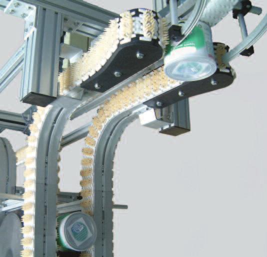
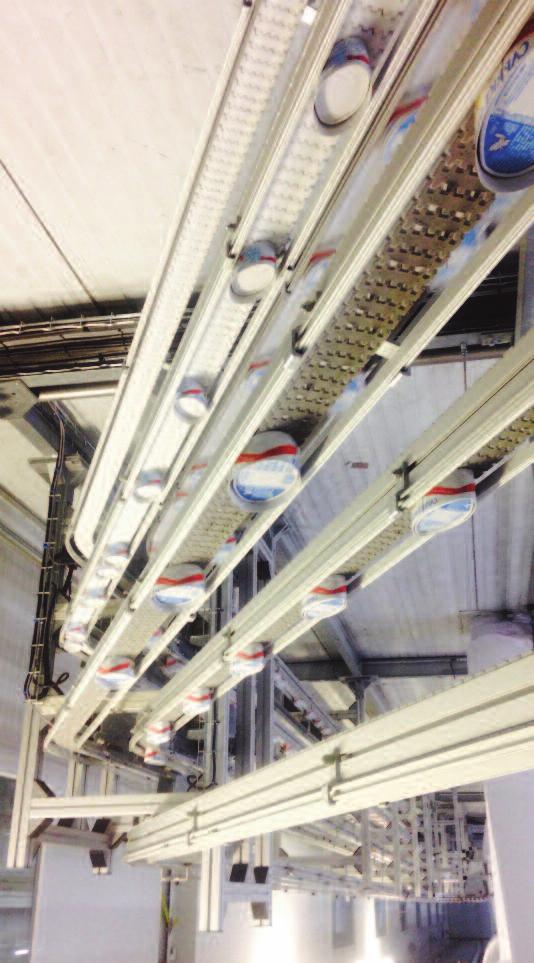
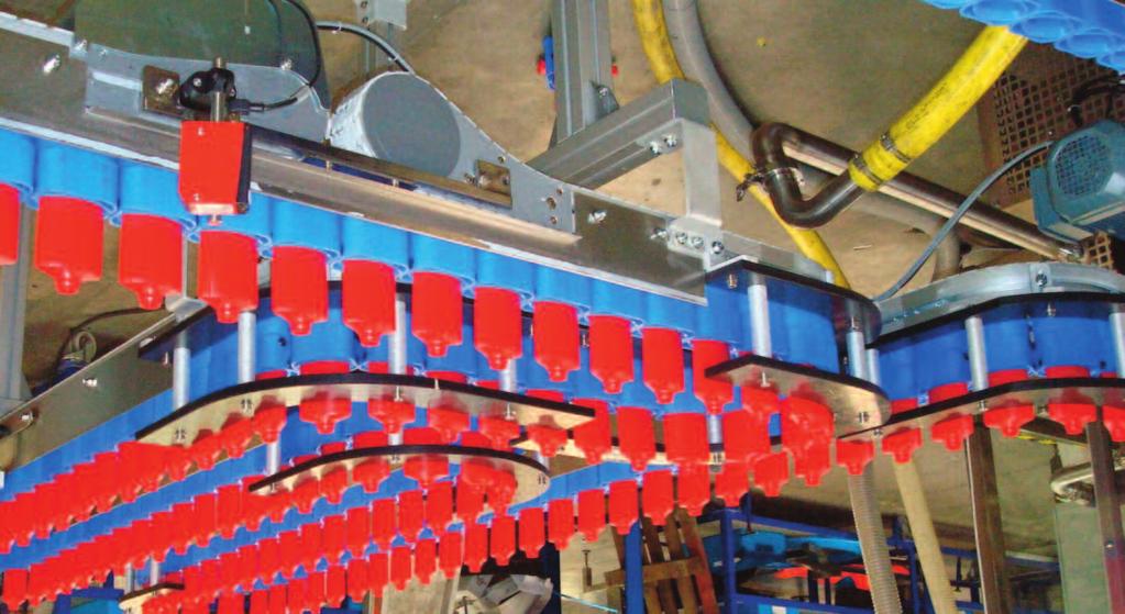
110 CAB, CAB-SB Guides-Führungen Pieds-Legs-Ständer 110

111 Legs for conveyors CAB, CAB-SB Guides-Führungen Pieds-Legs-Ständer 111


112 Brackets between conveyors and horizontal cross pieces Aluminium brackets FAHBS... Mainly used between the horizontal cross piece and the conveyor legs. Generally the width L corresponds to that of the cross piece. Holes or slots for fastenings Ø8 unless indicated otherwise. Reference L H A B Figure FAHBS , FAHBS 40B FAHBS 60 99, FAHBS 62B FAHBS 62A FAHBS 74A 100 FAHBS 74B FAHBS 74C 135 FAHBS 74D FAHBS , Bracket FAHBS A 4 L H CAB, CAB-SB 5 6 Guides-Führungen B Attachment points to the outside Reference L H A B Figure FGRB FGRB L 7 Example: console mounting Pieds-Legs-Ständer 112 H


113 Attachment of conveyors to vertical tubes Aluminium brackets FAVBS... mainly used between conveyors and vertical tubes. Holes or slots for fastenings Ø8 unless indicated otherwise. Conveyor F45 FK FS FK FS FM FC FK FS FM FC FK FS FM FC FS FM FC Vertical tube TC44 5 TC64 TC88 Compatible - chute - cable raceway 5 4 F45VBS FAVBS 40S FAVBS 40M FAVBS 60K FAVBS 60S FAVBS 60M FAVBS 60C FAVBS 60KV FAVBS 60SV FAVBS 60MV FAVBS 60CV FAVBS 60K FA FAVBS 60S FA FAVBS 60M FA FAVBS 60C FA 5 FAVBS 88S 4 Reference L B Figure FAVBS 88M FAVBS 88C L CAB, CAB-SB 5 6 Guides-Führungen B 113 Pieds-Legs-Ständer

 CAB, CAB-SB FBSB 15X44 44 TC44 44 BTC44 M8 (ØM8) FBEC")

114 Structural tubes, end pieces for aluminium profile, profiles for housings FBSB 24X24 FBSB 24X34 FBSB 24X FBEC FBEC 24x34 24 FBEC 24x44 CA FBSB 40X40 (Tappable ØM8) FBEC 40 Tappable central hole ØM8. (ØM10 or ØM12 after drilling) CAB, CAB-SB FBSB 15X44 44 TC44 44 BTC44 M8 (ØM8) FBEC 44 Guides-Führungen Pieds-Legs-Ständer 15 FBEC 15x44 Profile for housing JEC4 11 Allows installation of a panel th. 4 to 7 mm into the 11 mm groove in our profiles FBSB 44X44M (Tappable ØM8)


 70 FEFU used to")
")
115 Structural tubes, ends for aluminium profile, profiles for housings x 64 FBSB 44X64 TC64 FBSB 64x64M FBEC 44x64 4 x (Tappable ØM8) FBEC 64 FBSB 64x64C 44 x 88 TC TC88 FBSB 44x88M FBEC 44x88 FBSB 88x88M FBEC 88 CAB, CAB-SB 2 x (Tappable ØM8) 70 FEFU used to construct telescopic legs with 2 tubes FBSB 64x64M and TC x (Tappable ØM8) Guides-Führungen Pieds-Legs-Ständer


116 Zinc plated steel brackets for structural tubes FBRX 20A thickness 4 mm 2 M8 pressure screws included 20 FBRX 20B thickness 4 mm 1 M8 pressure screw and 1 M8 bolt included 20 FBRX 20C thickness 4 mm 4 pressure screws included FBRY 20 thickness 3 mm 2 HM8 screws included Reference FBRY 20A 90 FBRY 20x45A 45 thickness 3 mm, without fastenings, holes 8.5 x 11 A 30 FBFA 100A CAB, CAB-SB A Guides-Führungen FBRW 20 thickness 4 mm 2 M8 pressure screws included FBRW 20X45 thickness 4 mm 2 M8 pressure screws included Reference A FBCP 60L 90 FBCP 60X45 45 thickness 6 mm Pieds-Legs-Ständer A


117 Aluminium or light alloy brackets for structural tubes Brackets: moulded or cut from profile section Bracket: FBAB 20 (Fastenings M5) Bracket: FBFA Fixed hinge: FBFJ 44F Adjustable hinge: FBFJ FBFA 38A 38 Bracket: FBFA 38B End plug: BE FBFA 38B 38 FBFA 38C FBRX 13 für AT30, AC2A8, FGGR 3x20x12 Bracket: FBFA 58B End plug: BE FBFA 58B Winkel FBAB 60L Bracket: FBFA 88C Bracket: FBFA Bracket: FBFA 88B End plug: BE FBFA 88B 44 Guides-Führungen CAB, CAB-SB Pieds-Legs-Ständer


118 Square tube leg bases Aluminium bases For square tube TC 44 TC 64 TC 88 Base reference EC FBFT 64 EC Dimensions 150 x 150 x H x x 260 Connection to the vertical tube 6 screws HM6 x 16 6 square nuts M8 + spring washers Fastenings included Fastenings included Floor anchorage Ø 10 Ø 10 Ø 16 Plastic feet moulded for square profiles Plates for structural tubes Guides-Führungen CAB, CAB-SB Pieds-Legs-Ständer For tube TC64 jacks included For tube TC64 70x70 Bipod reference FBFT 64BP Tripod reference FBFT 64TP FEFG 70T jacks included Adjustment jack FBAF M20x56 for FBFT 64BP or FBFT 64TP Anti-vibration sole plate FLFJ 69 optional for FBAF M20x56 ØM20 ØM20 ØM20 Ø70 Ø For tube Plate reference Mountings Figure TC44 FBSB-44x64 TC TC64 FBSB 64x64M TC88 FBFE 44M8 FBFE 44M12 FBFE 44x64M12 FBFE 44x88M12 FBFE 64M12 FBFE 88M12 FAFB 88F x ØM8 4 x Ø 6 1 x ØM12 4 x Ø 6 4 x Ø 6 4 x Ø
 84 R2")
 84 30 62")


 Adjustable plates for inclined feet reference L")
119 Mountings on beams R2 SL32P Aluminium clip with mobile rocker for lower mounting (2 holes ØM8) 84 R2 SL32PL Aluminium clip with mobile rocker for lateral mounting or inclined conveyor (2 holes ØM8) ,4 25,4 EPR Aluminium profile with 3 grooves for M8 nut or bolt head. Is used between clips R2SL32P and support head 331-4, for, Cobral or other conveyors. EMEPR Closing end piece for profile EPR below U CLAMP Clamp for feet, 1 R1 SL1/21.5M Moulded plastic clip for stirrup U (legs for 1) Adjustable plates for inclined feet reference L PL1 84 PL CAB, CAB-SB Guides-Führungen L Pieds-Legs-Ständer


120 Round tubes Support heads and junction TUA 60 4R Aluminium profile with 4 grooves for M8 nut or bolt head. These grooves can be plugged by an optional cover: red CR8R, black CR8N2 or grey CR8G2 TUX 60 Smooth stainless steel tube Ø 60.3 thickness 2 CAB, CAB-SB BTC M16 End M16 for TUA 60 4R Smooth tubes Ø 42.4 thickness 1.6 mm Material Reference aluminium TUA 42 stainless steel TUX 42 BTR M16 M16 end piece for TUA 60 TUX60 Guides-Führungen Support head For tubes TUA 60 4R or TUX60 Junction between tubes TUA 60 4R or TUX 60 and TUA 42 or TUX 42 Lateral support head for tubes TUA 60 4R or TUX 60 Pieds-Legs-Ständer 120


: ØA H Swivel castor with brake: ØM tube")
 H 331 80 M8 331 80 M10 80 94 A49 125 M10 M10.")
 60 150 331 80 M16 80 95 331 80 M16GH 145 A49 125 M16 M16 FBFA")
 Ø M 121 331 3, 331 2 or 331 2 120 BTC M16")
121 Leg bases (feet) for tubes Ø60.3 Jacks/sole plates Ø moulded tripod foot in Black PA6 for tube Ø Moulded bipod foot in black PA6 for tube Ø Moulded bipod foot in black PA6 for tube Ø60.3 to be used in cross braced pairs per tube Ø 42.4 ØM16 ØM16 97 ØM16 Spitable jack except (*): ØA H Swivel castor with brake: ØM tube FBSB 40x40... plate for base above end piece (/of tube) H M M A M10 M10... M10 tapped M12 94 A M12 M12... M12 tapped FBFE-...-M M12GH (*) M M16GH 145 A M16 M16 FBFA PC 88 Ø M Ø A A M8 M8... M8 tapped FBFE44 M8 BTC44 M8 (/TC44) Ø M , or BTC M16 (/TUA60 4R) BTR M16 (/TUX 60) Note: L fitted with castors must be cross braced with for example Ø42 tubes and junction to improve their stability and strength. Zinc plated steel bracket for floor mounting of profiles 40 mm Connection to the vertical tube Ø8 floor anchorage: Ø12 Guides-Führungen CAB, CAB-SB Pieds-Legs-Ständer


 Bipod foot (C.")


 multi-track version inclined")
122 Square tube legs for and conveyors CAB, CAB-SB conveyor Square profile 44 Square profile 64 Profile TC-88 (C.88) Tripod foot (C.64) Bipod foot (C.64) F45 F45TC 44 FK-FT-FH FKTC 44 FKTC 64 FKTC 3 FKTC 2 FS FSTC 44 FSTC 64 FSTC 88 FSTC 3 FSTC 2 FM FMTC 64 FMTC 88 FMTC 3 FMTC 2 FC FCTC 64 FCTC 88 FCTC 3 FCTC 2 Possible variants Inclined conveyor Inclined conveyor Inclined conveyor Inclined conveyor B Guides-Führungen Pieds-Legs-Ständer Conveyor FL FLPC 64 FLPC FLTC F2 750 PC 64 F2 750 PC F2 750 PH40 F2 750 PH44 F2 750 TC F PC 64 F PC F PH40 F PH44 F TC F PC 64 F PC F PH40 F PH44 F TC * F PC 64 F PC F PH40 F PH * F PH40 F PH44 Possible variants Square profile 64 multi-track version inclined conveyor swivel leg Profile PC88 (C.88) multi-track version inclined conveyor 122 B Leg PH40 (C.40) Leg PH44 (C.44) Tripod foot (C.64) multi-track version inclined conveyor

 CAB.")
 CAB.")
 CAB.")


123 Square tube legs for CAB conveyors CAB conveyor Square profile 64 CAB...PC64 Profile PC88 (C.88) CAB...PC88 Leg PH40 (C.40) CAB...PH40 Leg PH44 (C.44) CAB...PH44 Bipod foot (C.64) CAB...TC3 Tripod foot (C.64) CAB...TC3 CAB 6 CAB 6 PC64 CAB 6 PC88 CAB 6 PH40 CAB 6 PH44 CAB 6 TC2 CAB 6 TC3 CAB 9 CAB 9 PC64 CAB 9 PC88 CAB 9 PH40 CAB 9 PH44 CAB 9 TC2 CAB 9 TC3 CAB 12 CAB 12 PC64 CAB 12 PC88 CAB 12 PH40 CAB 12 PH44 CAB 12 TC2 CAB 12 TC3 CAB 15 CAB 15 PC64 CAB 15 PC88 CAB 15 PH40 CAB 15 PH44 CAB 15 TC2 CAB 15 TC3 CAB 18 CAB 18 PC88 CAB 18 PH40 CAB 18 PH44 CAB 21 CAB 21 PH40 CAB 21 PH44 CAB 24 CAB 24 PH40 CAB 24 PH4 H min. Without cable raceway 530 mm 555 mm 315 mm 478 mm 575 mm With cable raceway 577 mm 600 mm 370 mm 478 mm 623 mm Legs for special situations: Single leg for mounting geared motors Swivel leg Height-adjustable stand, with telescopic square tubes CAB, CAB-SB multi-track leg for parallel conveyors Guides-Führungen "H shaped legs may be cross braced for better stability Pieds-Legs-Ständer 123


 FK 4 FK P3 FK")


124 Ø60.3 tube legs for, and conveyors Conveyor Figure Tripod leg Bipod leg Conveyor Figure Tripod leg Bipod leg 1 1 R1 P3 R1 P2 2 / 2TB R2 P3 R2 P2 3 / 3TB 2 R3 P3 R3 P2 4 2 R4 P3 R4 P2 Possible variants multi-track version inclined conveyor (Figure 3) FK 4 FK P3 FK P2 FS 4 FS P3 FS P2 FM 5 FM P3 FM P2 FC 5 FC P3 FC P2 FL 4 FL P3 FL P2 Guides-Führungen Pieds-Legs-Ständer CAB, CAB-SB Conveyor Tripod foot Bipod foot Tetrapod foot Reference Reference Reference -750 F2 750 P3 F2 750 P F P3 F P F P3 F P F P3 F P * F P


125 Ø60.3 tube legs Conveyors CAB conveyor Bipod foot CAB...P2 Tripod foot CAB...P3 Tetrapod foot CAB...2P2 120 CAB 6 CAB 6 P2 CAB 6 P3 CAB 9 CAB 9 P2 CAB 9 P3 CAB 12 CAB 12 P2 CAB 12 P3 CAB 15 CAB 15 P2 CAB 15 P3 CAB 18 CAB 18 P2 CAB 18 P3 CAB 18 2P2 120 CAB 21 CAB 21 2P2 120 CAB 24 CAB 24 2P2 120 H min. Without cable raceway 540 mm With cable raceway 595 mm Option: legs on casters The adjustment jacks are replaced by braked swivelling casters A M16. The reference of the leg has the suffix R. CAB, CAB-SB Note: To avoid the instability of legs fitted with castors, they must be cross braced Guides-Führungen Pieds-Legs-Ständer 125


126 Ø60.3 stainless steel tube legs for In the top part, a stirrup is placed between the horizontal modules and the support head. Fixing by Ø9 holes L Clamp SAHBS CAB, CAB-SB Guides-Führungen Range SS SM SC Bipod foot reference SS P2 SM P2 SC P2 Tripod foot reference SS P3 SM P3 SC P3 Width L Clamp SAHBS 90S SAHBS 90M SAHBS 90C Detail of the mounting of the attachment stirrup on the beam Pieds-Legs-Ständer 126


 Cable raceways FBEC 44 FBEC 44 88 FBEC 88")

 CABLE UF 54x100 1 2 Zinc plated steel")


 internal partition")
127 Cable raceways Aluminium cable raceways with covers Standard length 3m Fish plates not included: FACS 20x130a; compatible fastenings: FASN..., FAHN..., FATB..., and FASB... on page 104. Cover FBCC 44 FBCC 88 FBCD 44 (44 x h.44) FBCD 44x88 (88 x h.44) FBCD 88 (88 x h.88) Cable raceways FBEC 44 FBEC FBEC 88 End plug Welded wire cable raceways Reference Item 8 Wire cable raceway Zinc plated steel (100 x h.54 mm) CABLE UF 54x Zinc plated steel cover (option) CVR UF100 2 Fish plate ECLISSE UF300 3 Mounting clips CLIPS UF 4 Backing plate CLAME UF 5 Self-locking nut ØM6 ECROU TWOLOCK M6 6 Small fish plate ECLISSE UF30 7 Side Bracket PATTE UF 8 Steel cable raceways Cable raceway (100 x h.54 mm) internal partition (option) Exists straight and curved CAB, CAB-SB Guides-Führungen 127 Pieds-Legs-Ständer


128 Drain gutters and trays for the FK, FS, FM and FC ranges They are used to keep workshops safe and clean when wet or oily parts are transported. They can also be used to secure conveyors with lug chains. Chute FxDT End piece FxDC Top chutefxdv...bu End piece FxDD Bottom chute FxDV...BL Junction FxDJ Conveyor Width of conveyor Chute width W FK 45 FS FM FC CAB, CAB-SB Aluminium chutes length 3 m for straight modules Conveyor Straight chutes W Junction trays H FK-FS FSDT 3x10⁷B 107 FSDJ 107B 90 FM FMDT 3x127B 127 FMDJ 127B 111 FC FCDT 3x147B 147 FCDJ 147B 108 W Guides-Führungen Chute mounting system FADB 21x100 Junction trays F...DJ... are used to assemble 2 lengths of aluminium chutes together. Curves or end chutes do not require connecting pieces. Additional possibility of fish plating with FACS-20x130A. H Pieds-Legs-Ständer Spacer FGRD-10 (th. 10) for FK series 128 W


 Conveyor R 30 45 90 180 FK-FS 227 FSDV 30x107BU FSDV 45x107BU FSDV 90x107BU FSDV 180x107BU FM 310 FMDV 30x127BU")

 Conveyor R 30 45 90 180 FK-FS 330 FSDV 30x107BL FSDV 45x107BL FSDV 90x107BL FSDV 180x107BL FM 430 FMDV 30x127BL")
129 Drain gutters and trays for the FK, FS, FM and FC ranges Thermoformed chutes End pieces Conveyor Flat end piece Reference Hollow end piece Reference W Hd Ld End piece Lc FK-FS FSDE 107B FSDD 107B FSDC 107B 74 FM FMDE 127B FMDD 127B FMDC 127B 74 FC FCDE 147B FCDD 147B FCDC 147B 72 Hd W Male union Ø1/2'' gas Ld W Lc Thermoformed drain trays for curved modules with wheels For curves with wheels of... (α ) Conveyor L H R FK-FS FSDH 30x107B FSDH 45x107B FSDH 90x107B FSDH 180x107B FM FMDH 30x127B FMDH 45x127B FMDH 90x127B FMDH 180x127B FC FCDH 30x147B FCDH 45x147B FCDH 90x147B FCDH 180x147B W a R H L raccord Male union mâle Ø1/2'' Ø1/2 gas gaz Thermoformed chutes for vertical curves Top chutes for curves of... (α ) Conveyor R FK-FS 227 FSDV 30x107BU FSDV 45x107BU FSDV 90x107BU FSDV 180x107BU FM 310 FMDV 30x127BU FMDV 45x127BU FMDV 90x127BU FMDV 180x127BU W 80 R CAB, CAB-SB FC 310 FCDV 30x147BU FCDV 45x147BU FCDV 90x147BU FCDV 180x147BU Idem, with male union Ø1/2'' gas for curve of 90 FK-FS 230 FSDV 90x107B FM 310 FMDV 90x127B FC 310 FCDV 90x147B Bottom chutes for curves of... (α ) Conveyor R FK-FS 330 FSDV 30x107BL FSDV 45x107BL FSDV 90x107BL FSDV 180x107BL FM 430 FMDV 30x127BL FMDV 45x127BL FMDV 90x127BL FMDV 180x127BL FC 430 FCDV 30x147BL FCDV 45x147BL FCDV 90x147BL FCDV 180x147BL 129 W R 80 R 80 W Pieds-Legs-Ständer Guides-Führungen


130 Side mounting brackets Reference for L FAAL 64 TC FAAL 40 FBSB 40x40 or TC44 40 FAAL 88 bracket for post TC88 44 L 85,5 73,5 44 Application: serpentine Dimensions for curves with wheels and for posts (FS, FM, FC) W W / 2 D = 2 x R = W 235 E LP E Guides-Führungen CAB, CAB-SB Bracket E LP (post) FAAL square FAAL square Series W R 2x R - W FS FM FC Pieds-Legs-Ständer Another example of use 130


131 Components for adjustable wedge conveyors Adjustment module FGLA... for wedge elevators Reference Figure FGLA 660L 1 FGLA 950L Hand wheel FGAW FGAW 160x10A for wedge elevators Transmission pin FGFX 3 Ø25/12 grooved for corner pieces, length 3 m. Corner piece FGFW 90L 3 protruding shafts Ø10 pinned 88 x 88 x 69 CAB, CAB-SB Guides-Führungen Example of application of the brackets on the previous page: Lateral mounting of wedge conveyors on adjustment modules FGLA... Pieds-Legs-Ständer 131

* 0,63 0.")


 Adjustment range of the thermal circuit breaker (A) Version")

132 Pieds-Legs-Ständer Guides-Führungen CAB, CAB-SB Starter boxes Direct starters with motor circuit breaker, switch and emergency stop for 3-phase motor 400 V 50 Hz Compliance with standards IEC , IEC , polycarbonate material Motor power (* number of poles) 60 W 0, , DRTA02 DRTB02 DRTC02 90 W 0, , DRTA03 DRTB03 DRTC & 180 W 0, , DRTA04 DRTB04 DRTC & 370 W (2p/4p)* 0, DRTA05 DRTB05 DRTC W (6p)* & 550 W 1-1,6 1.6 DRTA06 DRTB06 DRTC W & 1,1 1.1 kw 1, ,5 2.5 DRTA07 DRTB07 DRTC07 1,5 1.5 kw 2, DRTA08 DRTB08 DRTC08 2,2 2.2 kw 4-6,3 6.3 DRTA10 DRTB10 DRTC10 Supply 3-phase phase 400+N Possibility of remote emergency stop 5 4 in 230 V 4 in 24 V Type, mains power and current of the Movimot variable speed drive MM03 370W 1,3A 1.3A MM05 550W 1,6A 1.6A 1-1,6 1.6 DRTA06M DRTB06M DRTC06M MM07 0, kw 1,9A MM11 1,1 1.1 kw 2,4A 2.4A 1, ,5 2.5 DRTA07M DRTB07M DRTC07M MM15 1,5 1.5 kw 3,5A 3.5A 2, DRTA08M DRTB08M DRTC08M Supply 3-phase phase 400+N Possibility of remote emergency stop 5 4 in 230 V 4 in 24 V 132 Adjustment range of the thermal circuit breaker (A) Adjustment range of the thermal circuit breaker (A) Version A Version A Locking emergency stop (option) Suffix to be added at the end of the starter reference: OC can be supplied as an accessory ref: DRTOC Version B Version B Version C Version for Movimot variable speed drive fitted with a motor on-off control, enabling the integral functionalities of the variable speed drive (acceleration / deceleration slopes) to be used. Control +/- fast (option) Version C Emergency stop, compatible with versions B and C ref: DRTAU
133 Index of references 133 Pieds-Legs-Ständer Guides-Führungen CAB, CAB-SB
134 Guides-Führungen CAB, CAB-SB Pieds-Legs-Ständer 134
135 _ROBUR _ROBUR N-ROBUR N_ROBUR N_ROBUR _ROBUR M12GH M M M M16GH M8 121 A A M A M A M A M8 121 AC2A8 88 AF12/8 120CC 100 AF703CC 100 AF710CC 100 AF712CC 100 AF720CC 100 AFPOCC 100 B BAGUE D ARRET D BAGUE D ARRET D BAGUE D ARRET D BAGUE D ARRET D BAGUE D ARRET D BAGUE D ARRET SQ BE FBFA 38B 117 BE FBFA 58B 117 BE FBFA 88B 117 Bouchon FGEC BTC M BTC44 M8 114 BTR M BUTEE CONIQUE 105 BUTEE PIVOT 105 C C2010X 88 C2010Z 88 CA CAB PG 80 CAB-SB 84 CAB CV500 B 82 CAB CV500 H 82 CAB D 81 CAB MDD 82 CAB MDG 82 CAB R 82 CAB RS 82 CAB TG1 82 CAB TG2 82 reference index page page page CABLE UF 54x CACHE VIS FHC 104 CACHE-ECROU HM6 104 CACHE-ECROU HM8 104 CJF2 FM 105 CJR C 105 CLAME UF 127 CLIPS UF 127 CMCB 3 40 CMCT 5A12 L 39 CMCT 5A15 L 39 CMCT 5A17 L 39 CMCT 5A30 L 39 CMCT 5A9 L 39 CMCT5 D125L 39 CMCV 5B 39 CMDD TL 0L 41 CMDD TL 0R 41 CMFC 5 39 CMFT 5 39 CMFT 5A 39 CMFT 5C 39 CMFT 5F 39 CMHB 42 CMIE CMPC 5 39 CMPC 5 CD 39 CMPC 5P 39 CMPC 5R CMPC 5WR 39 CMSR CMSR 25A 49 CMSR 25B 49 CMSR 25H 49 CMSR 25P 49 CMSR 3 49 CMST 5 39 CMUC 5 39 CMVB 42 CMWB 41 CMWT 5C 39 CPS 24 CR8G2 92 CR8N2 88 CVR UF D DRTA 132 DRTAU 132 DRTB 132 DRTC 132 DRTOC 132 E ECLISSE UF ECLISSE UF ECQA 40 M6 102 ECQA 40 M8 102 ECQA 40 M8 ACIER 102 ECQA/45 M6 102 ECQA/45 M8 102 ECQA/45 M8 ACIER 102 EL EL EL EL EL60 88 EL92 88 Embout-CCD EMEPR 119 EMFT 5R 13 EMFT 5R-L 13 EMPC 5HT 12 EMPC 5R 12 EO 12x12 97 EO 20x20 97 EPR 119 F F C640/90 57 F CV F D F MDD GP 59 F MDD F MDG GP 59 F MDG F MID20 59 F MSD30 59 F MSG30 59 F P2 124 F P3 124 F PC F PC F PH F PH F R 58 F RP 58 F TC F TG1M 58 F TG1R 58 F TG2M 58 F TG2R 58 F TMDM NTB 58 F TMDR NTB 58 F TMGM NTB 58 F TMGR NTB 58 F C800/90 57 F CV F D F MDD GP 59 F MDD F MDG GP 59 F MDG F MID20 59 F MSD30 59 F MSG30 59 F P2 124 F P3 124 F PC F PC F PH F PH F R 58 F RP 58 F TC F TG1M 58 F TG1R 58 F TG2M 58 F TG2R 58 Pieds-Legs-Ständer Guides-Führungen CAB, CAB-SB
136 Pieds-Legs-Ständer Guides-Führungen CAB, CAB-SB F TMDM NTB 58 F TMDR NTB 58 F TMGM NTB 58 F TMGR NTB 58 F P F C930/90 57 F CV F D F MDD GP 59 F MDD F MDG GP 59 F MDG F MID20 59 F MSD30 59 F MSG30 59 F P3 124 F PC F PC F PH F PH F R 58 F RP 58 F TG1M 58 F TG1R 58 F TG2M 58 F TG2R 58 F TMDM NTB 58 F TMDR NTB 58 F TMGM NTB 58 F TMGR NTB 58 F P F C1180/90 57 F CV F D F MDD GP 59 F MDD F MDG GP 59 F MDG F MID20 59 F MSD30 59 F MSG30 59 F PH F PH F R 58 F RP 58 F TG1M 58 F TG1R 58 F TG2M 58 F TG2R 58 F TMDM NTB 58 F TMDR NTB 58 F TMGM NTB 58 F TMGR NTB 58 F2 750 C400/90 57 F2 750 CC F2 750 CV F2 750 D F2 750 MDD GP 59 F2 750 MDD F2 750 MDG GP 59 F2 750 MDG F2 750 MID20 59 F2 750 MSD30 59 F2 750 MSG30 59 F2 750 P2 124 reference index page page page F2 750 P3 124 F2 750 PC F2 750 PC F2 750 PH F2 750 PH F2 750 R 58 F2 750 RP 58 F2 750 TC F2 750 TG1M 58 F2 750 TG1R 58 F2 750 TG2M 58 F2 750 TG2R 58 F2 750 TMDM NTB 58 F2 750 TMDR NTB 58 F2 750 TMGM NTB 58 F2 750 TMGR NTB 58 F45CB 36 F45CV 3E 36 F45DD F45DD 9 37 F45FC 3 36 F45FT 3 36 F45HB 38 F45ID 37 F45IE F45PC 3 36 F45SR 25H 49 F45TC F45VB F45VBS F45WT 3C 36 FAAC 2 50 FAAC 3P 50 FAAL FAAL FAAL FACS 11x FACS 20x130A 50 FACS 20x FACS 20x140A 50 FACS 20x FACS 25x140A 50 FACS 25x FACS 25x70 50 FACS FADB 21x FAFB 88F 118 FAHBS FAHBS 40B 112 FAHBS FAHBS 62A 112 FAHBS 62B 112 FAHBS 74A 112 FAHBS 74B 112 FAHBS 74C 112 FAHBS 74D 112 FAHBS FASB FASB FASC FASR 1.2 T 49 FASR 25A 49 FASR 25H 49 FASR 25K 49 FASR 25KA 49 FASR 25KH 49 FASR 25KP 49 FASR 25P 49 FASR 25U 49 FASR 3X 49 FASR 75x15M 105 FASR 75x19P 105 FATB FATB FATB FATB FATB FATB FATBX FATBX FATBX FATBX FATBX FATBX FAVBS 40M 113 FAVBS 40S 113 FAVBS 60C 113 FAVBS 60C FA 113 FAVBS 60CV 113 FAVBS 60K 113 FAVBS 60K FA 113 FAVBS 60KV 113 FAVBS 60M 113 FAVBS 60M FA 113 FAVBS 60MV 113 FAVBS 60S 113 FAVBS 60S FA 113 FAVBS 60SV 113 FAVBS 88C 113 FAVBS 88M 113 FAVBS 88S 113 FB 175 HB 42 FB 295 HB 42 FB175 CB3 40 FB175 CD 3A 39 FB175 DD 0L 41 FB175 DD 0R 41 FB175 FT 3A 39 FB175 IE FB175 PC 3A 39 FB175 RC 3A 39 FB175 VB 42 FB295 CB3 40 FB295 DD 0L 41 FB295 DD 0R 41 FB295 FT 3A 39 FB295 IE FB295 PC 3A 39 FB295 VB 42 FBAB FBAB 60L 117 FBAF M20x FBCC FBCC FBCD FBCD 44x FBCD FBCP 60L 116 FBCP 60X FBCS 13x50 50
137 FBCS 19x50 50 FBCS 20x55 50 FBEC 15x FBEC FBEC 24x FBEC 24x FBEC FBEC FBEC 44x FBEC 44x FBEC FBEC FBFA 100A 116 FBFA FBFA 38A 117 FBFA 38B 117 FBFA 38C 117 FBFA 58B 117 FBFA FBFA 88B 117 FBFA 88C 117 FBFA PC 121 FBFE 44M FBFE 44M8 118 FBFE 44x64M FBFE 44x88M FBFE 64M FBFE 88M FBFE44 M8 121 FBFJ FBFJ 44F 117 FBFP FBFT 64BP 118 FBFT 64TP 118 FBMJ 6P 50 FBMR FBRB 22x63 95 FBRW FBRW 20X FBRX FBRX 20A 116 FBRX 20B 116 FBRX 20C 116 FBRY FBRY 20A 116 FBRY 20x45A 116 FBSB 15X FBSB 24X FBSB 24X FBSB 24X FBSB 40X FBSB 44X44M 114 FBSB 44X FBSB 44x88M 115 FBSB 64x64C 115 FBSB 64x64M 115 FBSB 88x88M 115 FC P2 124 FC P3 124 FCCB 3R 24 FCCC FCCD DD 0L 29 FCCD DD 0R 29 FCCD SD 0L 29 FCCD SD 0R 29 reference index page page page FCCT 5A15 20 FCCT 5A17 20 FCCT 5A20 20 FCCT 5A30 20 FCCT 5A40 20 FCCV 5B 22 FCDC 147B 129 FCDD 147B 129 FCDD A105 0L 26 FCDD A105 0R 26 FCDD A105GP 0L 27 FCDD A105GP 0R 27 FCDD-PCB 26 FCDE 147B 129 FCDH 129 FCDJ 147B 128 FCDT 3x147B 128 FCDV 129 FCFC 5 13 FCFT 5 13 FCFT 5A 13 FCFT 5B 13 FCFT 5B LF 13 FCFT 5D 13 FCFT 5E 13 FCHAB 5 32 FCHB 32 FCIB FCID DD 0L 28 FCID DD 0R 28 FCID SD 0L 28 FCID SD 0R 28 FCIE 280P 25 FCIE A FCIE-PCB 26 FCMJ 6 50 FCMR FCMT 5 14 FCPC 5 12 FCPC 5CD 12 FCPC 5GF 12 FCPC 5HT 12 FCPC 5LF 12 FCPC 5P 12 FCPC 5UV 12 FCPC 5V 12 FCPC 5VHT 12 FCPC 5VR 12 FCPC 5WR 12 FCRB 5A 21 FCRB 5B 21 FCRC 5A 16 FCRC 5A L 16 FCRC 5B 16 FCRC 5B L 16 FCRM FCRM FCRP FCRT 5 16 FCSD A105 0L 27 FCSD A105 0R 27 FCST 5 13 FCST 5S 13 FCST 5S NF 13 FCTB FCTB 105PSD 25 FCTB 105SD 25 FCTB FCTB 280P 25 FCTB A FCTB A105P 25 FCTC 122 FCVAB 5 33 FCVB FCWB FCWD DD 0M 31 FCWD SD 0M 31 FD7 89 FEFG 70T 118 FEFU 115 FGAP FGAR 6x20 99 FGAW 160x10A 131 FGCB 1 90 FGCB 2 90 FGCD FGCR 1 90 FGCR 2 90 FGDT FGDT FGDT FGDT 3x FGDT FGEC 10x20 92 FGEC 12x20 92 FGEC 15x20 93 FGEC FGEC 30D FGEC C1 90 FGEC C2 90 FGEC L1 90 FGEC L1A 90 FGEC L2 90 FGFW 90L 131 FGFX FGGR 18xL 95 FGGR 3x18 95 FGLA 660L 131 FGLA 950L 131 FGLB 1 90 FGLB 1C 91 FGLB 2 90 FGLB 2C 91 FGLR 1 90 FGLR 1C 91 FGLR 2 90 FGLR 2C 91 FGPR FD FGRA FGRB 11x30C 99 FGRB 16x42C 99 FGRB 16x54C 99 FGRB 18x18 97 FGRB 18x20 97 FGRB 18X20T 97 FGRB 20x20 97 FGRB 20X20T 97 FGRB FGRB 40x15x20 98 FGRB 40x18 98 Pieds-Legs-Ständer Guides-Führungen CAB, CAB-SB
138 Pieds-Legs-Ständer Guides-Führungen CAB, CAB-SB FGRB 40x20 98 FGRB 40x42C 99 FGRB FGRB FGRC FGRC 18x110C 94 FGRC 18x160C 94 FGRC FGRC 20A 100 FGRC FGRD FGRD FGRD FGRD 18A 96 FGRD FGRD FGRD 30B 98 FGRD 3D 96 FGRD FGRD 6A 96 FGRD 6B 98 FGRD 6P 105 FGRF 40x12 98 FGRF 40x18 98 FGRF 42x18V 96 FGRF 42x18VH 96 FGRF A FGRF A35 99 FGRF DP 99 FGRJ 10x20 92 FGRJ 15x20 93 FGRJ 18x18 95 FGRK 18CE 95 FGRK 18x130A 94 FGRK 18x40A 94 FGRK 18x60A 94 FGRK 18x80A 94 FGRL 18x110C 94 FGRL 18x110CA 94 FGRL 18x160C 94 FGRL 18x160CA 94 FGRN 3U 96 FGRR 3x20x10 92 FGRR 3x20x10 B 92 FGRR 3x20x10 F 92 FGRR 3x20x10P 92 FGRR 3x20x10T 92 FGRR 3x20x12 92 FGRR 3x20x15P 93 FGRR FG25 92 FGRRF 3x20x15 93 FGRS 15x20 95 FGRS FGRT 3x23 93 FGRT 3x23A 93 FGRT 3x33 93 FGRT 3x33A 93 FGRT 3x50 93 FGRX 15x20 97 FGRX 18x18 97 FGRX 18x20 97 FGRX 20x20 97 FK P2 124 FK P3 124 FK2R reference index page page page FK2R FKCC FKCD DD 0L 29 FKCD DD 0R 29 FKCT 5B 17 FKCT 5B FKCT 5B PBT 17 FKCT 5C 17 FKCT 5F3 L 18 FKCT 5F5 L 18 FKCT 5F9 L 18 FKCT 5J6 L 19 FKCT 5K20 L 19 FKCT 5K27 L 19 FKCT 5K3 L 19 FKCT 5K5.5 L 19 FKCT 5K9 L 19 FKCV 5B 22 FKCV 5C 22 FKDD 250 0L 26 FKDD 250 0R 26 FKDD A45 0L 26 FKDD A45 0R 26 FKDD A45GP 0L 27 FKDD A45GP 0R 27 FKFC 5 13 FKFT 5 13 FKFT 5C 13 FKHB 32 FKID DD 0L 28 FKID DD 0R 28 FKID SD 0L 28 FKID SD 0R 28 FKIE FKPC 5 12 FKPC 5CD 12 FKPC 5P 12 FKPC 5PV 12 FKPC 5UV 12 FKPC 5WR 12 FKRD FKRD FKRG FKRG FKSD A45 0L 27 FKSD A45 0R 27 FKST 5S 13 FKTB FKTB 200P 25 FKTB FKTB 45PSD 25 FKTB 45SD 25 FKTC FKTR 5 23 FKVAB 5 33 FKVB 33 FKWB FKWD DD 0M 31 FKWD SD 0M 31 FKWT 5A 15 FKWT 5C 15 FKWT 5D 15 FKWT 5DA 15 FKWT 5DB 15 FL P2 124 FL P3 124 FLCB 24 FLCC FLCD 5V 12 FLDD A150 0L 26 FLDD A150 0R 26 FLDD A150GP 0L 27 FLDD A150GP 0R 27 FLFC 5V 13 FLFJ FLFT 5V 13 FLHB 32 FLIE A FLPC 122 FLPC 5V 12 FLRC 5VB 16 FLRT 5V 16 FLSD A150 0L 27 FLSD A150 0R 27 FLTB FLTB 150PSD 25 FLTB 150SD 25 FLTB A FLTB A150P 25 FLTC 122 FLVB FLWB FLWD SD 0M 31 FM P2 124 FM P3 124 FMB FMCC FMCC 160D 24 FMCD DD 0L 29 FMCD DD 0R 29 FMCD SD 0L 29 FMCD SD 0R 29 FMCT 5A15 20 FMCT 5A17 20 FMCT 5A30 20 FMCT 5D40 L 18 FMCT 5D60 L 18 FMCT 5D80 L 18 FMCT 5F15 L 18 FMCT 5F20 L 18 FMCT 5F30 L 18 FMCV 5B 22 FMDC 127B 129 FMDD 127B 129 FMDD A85 0L 26 FMDD A85 0R 26 FMDD A85GP 0L 27 FMDD A85GP 0R 27 FMDD-PCB 26 FMDE 127B 129 FMDH 129 FMDJ 127B 128 FMDT 3x127B 128 FMDV 129 FMFC 5 13 FMFT 5 13 FMFT 5A 13 FMFT 5B 13 FMFT 5D 13 FMFT 5E 13
139 FMHAB 5 32 FMHB 32 FMIB FMID DD 0L 28 FMID DD 0R( 28 FMID SD 0L 28 FMID SD 0R 28 FMIE 260P 25 FMIE A85 25 FMIE-PCB 26 FMMJ 6 50 FMMR FMMT 5 14 FMPC 5 12 FMPC 5 R FMPC 5 R FMPC 5CD 12 FMPC 5GF 12 FMPC 5HT 12 FMPC 5LF 12 FMPC 5P 12 FMPC 5UV 12 FMPC 5V 12 FMPC 5WR 12 FMRB 5A 21 FMRB 5B 21 FMRB 5C 21 FMRB 5D 21 FMRC 5A 16 FMRC 5B 16 FMRC 5B L 16 FMRC 5C 16 FMRC 5C L 16 FMRT 5 16 FMSD A65 0R 27 FMSD A85 0L 27 FMST 5FA 13 FMST 5S 13 FMST 5S NF 13 FMTB FMTB 260P 25 FMTB FMTB 85PSD 25 FMTB 85SD 25 FMTB A85 25 FMTB A85P 25 FMTC 122 FMUC 5 14 FMUC 5-L 14 FMVAB 5 33 FMVB FMWB FMWD DD 0M 31 FMWD SD 0M 31 FMWT 5A 15 FMWT 5B 15 FMWT 5C 15 FMWT 5DA 15 FMWT 5DC 15 FS P2 124 FS P3 124 FS2R FSCC FSCD DD 0L 29 FSCD DD 0R 29 reference index page page page FSCD SD 0L 29 FSCD SD 0R 29 FSCT 5A12 20 FSCT 5A15 20 FSCT 5A17 20 FSCT 5A30 20 FSCT 5A4 20 FSCT 5A40 20 FSCT 5A FSCT 5A9 20 FSCT 5B 17 FSCT 5B FSCT 5B 51 PBT 17 FSCT 5B FSCT 5B 76 PBT 17 FSCT 5B PBT 17 FSCT 5C 17 FSCT 5C FSCT 5C 51 PBT 17 FSCT 5C PBT 17 FSCT 5D12 20 FSCT 5D15 20 FSCT 5D30 20 FSCT 5D5 20 FSCT 5E55 L 18 FSCT 5F15 L 18 FSCT 5F30 L 18 FSCT 5FL12 L 18 FSCT 5FR12 L 18 FSCT 5G12 20 FSCV 5A 22 FSCV 5B 22 FSCV 5C 22 FSCV 5D 22 FSCV 5E 22 FSCV 5F 22 FSDC 107B 129 FSDD 107B 129 FSDD 250 0L 26 FSDD 250 0R 26 FSDD A65 0L 26 FSDD A65 0R 26 FSDD A65GP 0L 27 FSDD A65GP 0R 27 FSDD-PCB 26 FSDE 107B 129 FSDH 129 FSDJ 107B 128 FSDT 3x10⁷B 128 FSDV 129 FSFC 5 13 FSFT 5 13 FSFT 5B 13 FSFT 5D 13 FSFT 5E 13 FSHAB 5 32 FSHB 32 FSIB FSID DD 0L 28 FSID DD 0R 28 FSID SD 0L 28 FSID SD 0R 28 FSIE FSIE A65 25 FSIE-PCB 26 FSMJ 4 50 FSMR FSMT 5 14 FSNS 5 14 FSPC 5 12 FSPC 5 R FSPC 5 R FSPC 5 R PBT 14 FSPC 5 R700 PBT 14 FSPC 5CD 12 FSPC 5GF 12 FSPC 5HT 12 FSPC 5LF 12 FSPC 5P 12 FSPC 5PBT 12 FSPC 5PV 12 FSPC 5UV 12 FSPC 5WR 12 FSRB 5C 21 FSRC 5A 16 FSRC 5A L 16 FSRM FSRM FSRP FSRT 5 16 FSRT 5 L 16 FSSD A65 0L 27 FSSD A65 0R 27 FSST 5FA 13 FSST 5S 13 FSTB FSTB 200P 25 FSTB FSTB 65PSD 25 FSTB 65SD 25 FSTB A65 25 FSTB A65P 25 FSTC 122 FSUC 5 14 FSUC 5-L 14 FSVAB 5 33 FSVB 33 FSWB FSWD DD 0M 31 FSWD SD 0M 31 FSWT 5A 15 FSWT 5B 15 FSWT 5BA 15 FSWT 5C 15 FSWT 5D 15 FSWT 5DA 15 FSWT 5DB 15 G GAB F2 56 GAB F45 49 GAB FK 49 GAB FM 49 GH5 1B 101 GH5 1PM 101 GH GH GH GH Pieds-Legs-Ständer Guides-Führungen CAB, CAB-SB
140 Pieds-Legs-Ständer Guides-Führungen CAB, CAB-SB J JEC K KPS 24 M MPS 24 P PAST M4x6 49 PAST M5x6 49 PAST M5x8 49 PATTE UF 127 PCPE 49 PL1 119 PL PRESSE D3 49 PRESSE D3 F45 49 PRESSE D3-F2 56 PRESSE D4 49 PSR CC 101 R R1 D 68 R1 MD20 69 R1 MG20 69 R1 P2 124 R1 P3 124 R1 PS 68 R1 R 69 R1 SL1/21.5M 102 R1 SL32-SL R1 SL32-SL R2 C R2 C R2 CV R2 D...x-MONO 73 R2 MD20 74 R2 MG20 74 R2 P2 124 R2 P3 124 R2 PS 73 R2 R 74 R2 SL1/17M 102 R2 SL2-H R2 SL2-H R2 SL32-SL R2 SL32-SL R2 SL32P 119 R2 SL32PL 119 R2 SLA R2TB D 68 R2TB FS 68 R2TB MD20 69 R2TB MG20 69 R2TB PS 68 R2TB R 69 R3 C R3 C R3 CV R3 D..x.-MONO 73 R3 MD20 74 reference index page page page R3 MG20 74 R3 P2 124 R3 P3 124 R3 PS 73 R3 R 74 R3TB D 68 R3TB FS 68 R3TB MD20 69 R3TB MG20 69 R3TB PS 68 R3TB R 69 R4 C R4 CV R4 MD20 74 R4 MG20 74 R4 P2 124 R4 P3 124 R4 PG 77 R4 PG-CD 77 R4 R 74 RI12 89 RIVET ALU 3X RIVET ALU 4X RIVET ALU 4X8 49 RONDELLE PA 8/ S SACS 50x75 50 SAHBS 90C 126 SAHBS 90M 126 SAHBS 90S 126 SC P2 126 SC P3 126 SCCB 45 SCCC SCDD 0L 44 SCDD 0R 44 SCDD GP 0L 44 SCDD GP 0R 44 SCID DD 0L 44 SCID DD 0R 44 SCIE SCTB SCTB 105P 44 SCVB 46 SCWB 46 SERT D3 49 SERT D4 49 SGEC SGGR 19x SGGR 19x SGGR 3x19 95 SGRB 18x18 97 SGRB 18x20 97 SGRB 18X20T 97 SGRB 20x20 97 SGRB 40x18 98 SGRB 40x20 98 SGRC 18x110C 94 SGRC 18x160C 94 SGRF 42x18V 96 SGRF A SGRF A35 99 SGRJ 3x19 95 SGRK 12x130A 100 SGRK 12x80A 100 SGRK 18x130A 94 SGRK 18x80A 94 SGRL 18x110C 94 SGRL 18x110CA 94 SGRL 18x160C 94 SGRL 18x160CA 94 SGRS SGRX 18x18 97 SGRX 18x20 97 SGRX 20x20 97 SM P2 126 SM P3 126 SMCB 45 SMCC SMDD 0L 44 SMDD 0R 44 SMDD GP 0L 44 SMDD GP 0R 44 SMID DD 0L 44 SMID DD 0R 44 SMIE SMTB SMTB 85P 44 SMVB 46 SMWB 46 SPS 24 SS P2 126 SS P3 126 SSCB 45 SSCC SSDD 0L 44 SSDD 0R 44 SSDD GP 0L 44 SSDD GP 0R 44 SSID DD 0L 44 SSID DD 0R 44 SSIE SSTB SSTB 65P 44 SSVB 46 SSWB 46 T TC TC TC TC TI12 89 TUA TUA 60 4R 120 TUX TUX U U ETRIER 119
141 Guides-Führungen CAB, CAB-SB Pieds-Legs-Ständer 141


142 Zone industrielle - rue Henri Dunant Bazeilles Tél. : +33 (0) info@faber.fr CORIS 1 bis rue de la Pompadour - ZI de la Haie Griselle Boissy-Saint-Léger Tél. : +33 (0) info@coris94.fr
EN. Modular conveyors. Flexmove. Flextoo. CAB Robur
 2018-1-EN Modular conveyors Flexmove Shared design work 1/2 Design of lines in 3D. 3 Performance check (speed, noise level, etc.). 4 Curve production by digital bending. 5/6 Integral finishing and assembly
FL SERIES: 150 mm Conveyor System
 : 150 mm Conveyor System Variety of chain type suitable for wide range of applications either horizontal or vertically product transportation. Capacity higher than FK, FS, FM. The maximum product width
SS 63mm Stainless Steel Conveyor System
 SS 63mm Stainless Steel Conveyor System SS FlexMove Product Catalogue 319 Variety of chain type suitable for wide range of applications either horizontal or vertically product transportation. FV Series
83mm Stainless Steel Conveyor System
 SM 83mm Stainless Steel Conveyor System SM FlexMove Product Catalogue 333 Variety of chain type suitable for wide range of applications either horizontal or vertically product transportation. SM Series
SC 103mm Stainless Steel Conveyor System
 SC 103mm Stainless Steel Conveyor System SC FlexMove Product Catalogue 347 Variety of chain type suitable for wide range of applications either horizontal or vertically product transportation. SC Series
150mm Conveyor System
 150mm Conveyor System FlexMove Product Catalogue 231 Variety of chain type suitable for wide range of applications either horizontal or vertically product transportation. Capacity higher than FK, FS, FM.
FS SERIES. FS Series Characteristic Beam Width: 65mm Product Width: Refer to Guide Rail Assembly
 SERIES Variety of chain types suitable for wide range of applications either horizontal or vertically product transportation. The maximum product width to be conveyed can be referred to guide rail assembly
300mm Conveyor System
 300mm Conveyor System FlexMove Product Catalogue 281 SERIES Variety of chain types suitable for wide range of applications either horizontal or vertically product transportation. The maximum product width
FC SERIES. FC Series Characteristic Beam Width: 105mm Product Width: Refer to Guide Rail Assembly
 Variety of chain type suitable for wide range of applications either horizontal or vertically product transportation. Capacity higher than FK, FS, FM. The maximum product width to be conveyed can be referred
Conveyor System ML2 ML2-1 MS2 MM3 ML2 MX2 DS2 DM3 DL2 DX2
 Conveyor System Description 140mm width thermoplastic chain with aluminium frame conveyor system. Also available with stainless steel frame, please refer section. Examples of application industries Personal
Conveyors 12. slide strips roller Conveyors roller elements Conveyor rollers Chain Transfer
 Conveyors slide strips roller Conveyors roller elements Conveyor rollers Chain Transfer Application example conveyors Transport solutions and goods provision 1 2 3 4 5 6 7 8 362 9 1 slide strips Low-wear
Description 315 mm width thermoplastic belt with aluminium frame conveyor system
 AP DF2 DR2 DT2 DX2 DL2 DM3 DS2 MA MB MG MF2 MR2 MT2 MX2 ML2 MM3 MS2 TR Conveyor System DT2 Description 315 mm width thermoplastic belt with aluminium frame conveyor system Examples of application industries
Conveyor system XH Contents System information Chain width 103 mm Technical characteristics Features Examples of application areas
 Conveyor system Contents System information...215 Chains...216 Chain accessories...217 Beams...217 Beam accessories...218 Slide rails...219 Slide rails, hardened steel...220 Drive and idler units introduction...221
FlexLink conveyor Series Y
 FlexLink conveyor Series Y 3 Introduction New conveyor with focus on hygiene The new FlexLink hygiene conveyor was designed to meet the following requirements of special interest to the dairy, food, and
Modular plastic belt conveyor WK
 Modular plastic belt conveyor Contents System information...405 Belts introduction...406 Belts...407 Conveyor sections...408 Conveyor frame components introduction...409 Conveyor frame components...410
Modular belt conveyor WL678X
 Modular belt conveyor 678X Contents System information...139 Conveyor sections...140 Modular Belts - Introduction...141 Modular belts...142 Conveyor Beams - Introduction...143 Conveyor frame components...145
Modular belt conveyor WL526X
 Modular belt conveyor 526X Modular plastic belt conveyor 526X Contents System information...123 Conveyor sections...124 Modular Belts - Introduction...125 Modular belts...126 Conveyor Beams - Introduction...127
Modular belt conveyor WL374X
 S Modular belt conveyor Contents System information...107 Conveyor sections...109 Modular Belts - Introduction...110 Modular belts...111 Conveyor Beams - Introduction...112 Conveyor frame components...114
Spartec CONVEYORS DESIGN MANUFACTURE INSTALLATION CONVEYORS
 DESIGN MANUFACTURE INSTALLATION PARTS SCRAP PACKAGE BULK HANDLING LOW PROFILE DIE-VEYORS 2 Frame Heavy Duty BELT WIDTH + 1 1/2" 3/4" BELT WIDTH 3/4" 2" 1" BELT WIDTH + 3/4" SECTION VIEW WIDTHS: 2 Thru
Modular plastic belt conveyor WL
 Modular plastic belt conveyor WL Contents System information...389 Conveyor sections...390 Belts introduction...391 Belts...392 Accessories for use with Friction top belt...392 Conveyor frame components
VarioFlow Lateral Guide Generation 2. Customer Presentation
 VarioFlow Lateral Guide Generation 2 Customer Presentation Market Requirements Your requirements: A compact, clearly designed lateral guide system for numerous standard applications and customized solutions
Stainless steel systems
 Stainless steel systems Copyright FlexLink 2014 The contents of this publication are the copyright of the publishers and may not be reproduced (even extracts) unless permission is granted. Every care has
Conveyor system FS F45 F65 F85 FLX FMX FHX ACC PAL IDX FB140 FB175 FB295 FS - TOOL SPIRAL FBX175 FBX295
 Conveyor system F45 FT FL F65 FM F85 FH FB140 FB175 FB295 SPIRAL FW FLX FMX FHX FBX175 FBX295 ACC Contents Chains 3 Conveyor beam 5 End drive units 7 Idler units 10 Horizontal wheel bends 12 Horizontal
At Dyno we make the world of business go round. Up and down. And side to side.
 Roller Catalogue 2017 SECTION At Dyno we make the world of business go round. Up and down. And side to side. Our conveyors make moving meat, veges, fruit, packages, gravel, and even luge sleds simple and
Design Innovative, robust construction, straight section eliminated before and after curve. Features Speed: Up to 70 meters per minute
 The new modular radius belt is available in different widths with a closed-top surface capable of handling a variety of package sizes, types and configurations including delicate products and applications
Stainless steel conveyor system X85X
 Stainless steel conveyor system XX Contents System information...27 Conveyor chain...28 Chain accessories...29 Conveyor beams...30 Slide rails...32 Tools for conveyor beam...33 Drive and idler units introduction...34
P1X Series. Compact Rodless Air Cylinders Contents
 Compact DL RC P1Z P1X OSP-P Contents Features and Benefits... 130 Ordering Information... 131 Specifications, Weights and Forces... 132 Technical Data... 133-136 Sensor Adapter Bracket... 137 Basic Dimensions...
CONVENTIONAL TURNOUTS
 RAILWAY CONVENTIONAL Basic description Turnout mounted in the track enables passing of the vehicle in either straight or branch direction. Depending on the design we distinguish the following types of
Modular transfer plates with rollers
 Modular transfer plates with rollers For heavy duty construction, and for bigger width please see page 328-330 Create a smooth transfer between two conveyors Can be used individually or back-to back Ultra
Stainless steel conveyor system X180X
 Stainless steel conveyor system XX Contents System information...43 Conveyor chain...43 Chain accessories...44 Conveyor beams...45 Slide rails...46 Tools for conveyor beam...47 Drive and idler units introduction...48
Ammeraal Beltech Modular
 Ammeraal Beltech Modular Innovative belt and chain solutions for every industry & application www.unichains.com Content Q2 updates - Chains page 4 Q2 updates - Straight Running Belts page 5 Q2 updates
Series R/W ratio, minimum*** L-curves X X X X. Work load in curve [N]
![Series R/W ratio, minimum*** L-curves X X X X. Work load in curve [N]](/thumbs/74/71445427.jpg "Series R/W ratio, minimum*** L-curves X X X X. Work load in curve [N]") Series 2351 2451 2551 2651 Name Standard Heavy Duty HD Small Radius SM HD-SM R/W ratio, minimum*** 1.6 1.6 1.0 1.0 S-curves X L-curves X X X X Work load in curve [N] 2500 3500 2500 3500 Load example 6x1.5
Series 2351 2451 2551 2651 Name Standard Heavy Duty HD Small Radius SM HD-SM R/W ratio, minimum*** 1.6 1.6 1.0 1.0 S-curves X L-curves X X X X Work load in curve [N] 2500 3500 2500 3500 Load example 6x1.5
Doors and fittings. Doors and fittings Aluminum Framing Hinge profile (p. 8-3) Hinge (p. 8-4) Hinge, plastic (p. 8-5)
 Hinge (p. 8-4) Hinge, plastic (p. 8-5)") Doors and fittings Aluminum Framing.0-1 Doors and fittings 1 4 Hinge profile (p. -) Hinge (p. -4) Hinge, plastic (p. -) Hinge, aluminum (p. -) 1 LIFTOFF hinge (p. -) Hinge, removable (p. -) Hinge, adjustable
Doors and fittings Aluminum Framing.0-1 Doors and fittings 1 4 Hinge profile (p. -) Hinge (p. -4) Hinge, plastic (p. -) Hinge, aluminum (p. -) 1 LIFTOFF hinge (p. -) Hinge, removable (p. -) Hinge, adjustable
ROLLERS SERIES 3500 Fixed drive conveyor roller. ROLLERS SERIES 3500 Fixed drive conveyor roller. Technical data
 Application area Driven unit handling conveying, such as transport of cardboards, containers, barrels or tires. Low-noise The use of polyamide drive heads results in very quiet running. Lateral loading
From a modest beginning in 1976 producing small. quantities of gravity conveyor rollers, Arnott Handling
 ARNOTT HANDLING LTD From a modest beginning in 1976 producing small quantities of gravity conveyor rollers, Arnott Handling Equipment Limited has grown to become one of the United Kingdom s foremost manufacturers
Conveyor system X180. System information X45 X65 X65P X85 X85P XKP X180 X300 ELV CTL FST APX IDX. Contents. Chain X180. Technical characteristics
 Conveyor system X1 Contents System information...271 Chains X1...272 Chain accessories X1...27 Beam components X1...27 Beam accessories X1...2 Slide rails X1...275 Drive and idler units introduction...276
Conveyor system FS FS -
 Conveyor system Contents Chains 3 Conveyor beam 5 End drive units 7 Idler units 10 Horizontal wheel bends 12 Horizontal plain bend 14 Vertical bends 16-1 Chains - 2 Chains Plain chain TP 5 Plain chain
Series SK Straight running plastic chains
 Series 80-83 - SK 38-8 - 857 Straight running plastic chains 80 STRAIGHT RUI CHAIS RD=50 38. 38. 7..5 3.5 9.5 Ø 6.35. STRAIGHT RUI CHAIS Series 80 Applications: Food and beverage industry: Conveying lines
CHAINS & BELTS PRODUCTION PROGRAM
 CHAINS & BELTS PODUCTION POGAM STAIGHT BELTS SIDEFLEXING BELTS SIDEFLEXING CHAINBELTS 2 INCH PITCH ½ INCH PITCH 1 ¼ INCH PITCH 1 INCH PITCH Imperial width Metric width Metric width Metric width Metric
Conveyor system XB. System information X45 XLP X85 X85P XKP FST XMY XLX XMX GRX CSX ELV CTL APX IDX. Chain width 175/295 mm.
 Conveyor system System information PO X45 XS Chain width 175/295 mm Features Chain travels on four slide rails. Wide track sideflexing safety chain. Compact horizontal and vertical bends. Suitable for
CONVEYING COMPONENTS 03/06/06
 CONVEYING COMPONENTS 03/06/06 PART NUMBER DESCRIPTION LIST F9-22-31-2-0 ZINC HEX NUT 1" UNC 1.365 0013200600 ROUND RED CAPPING FOR CURVE 5-MTR. 3.675 0013200600X1.5 ROUND RED CAPPING FOR OILER 7.7726 004217.20
TURNING DISK STEEL CHAINS:
 TURNING DISK STEEL CHAINS: Series 878TAB 324 327 MULTIFLEX CHAINS 328 331 878 TAB DRIVE AND IDLER DISK for sideflexing chains TANGENTIAL SPROCKETS Plain bore Ø 18.. 4 1 Ø18 Z B C M R 12817 32 337 32 29
Profile series I-40. System kit Profile series I-40
 Profile series I-40 System kit Profile series I-40 n n n a n n n R n a R 45 Profile series I-40 Contents 1 Technical data/profile machining F f Page 1 2 Page 1 3 Page 1 5 Page 1 8 Profiles Page 2 2 3000
Dynamic Elements Linear Slides Mechanical Drive Elements Accessories for Mechanical Drive Elements
 8 Dynamic Elements Mechanical Drive Elements Accessories for Mechanical Drive Elements The Dynamic Elements product group of the MB Building Kit System contains components which enable precise linear movement.
Conveyor system XK. System information X45 X65 X65P X85 X85P XKP X180 X300 ELV CTL FST APX IDX. Contents. Examples of application areas
 Conveyor system XK Contents System information...235 Chains XK...236 Chain accessories XK...237 Beams XK...237 Beam accessories XK...238 Slide rails XK...238 Slide rails, hardened steel XK...239 Drive
CONVEYOR COMPONENTS CONVEYORS. All Belts are available in a variety of pitches and materials. FREEFAX:
 Freephone lines are open between 8.00am and 5.pm 0800 80 CONVEYOR COMPONENTS Moody have been appointed as a unichain distributor, and are able to offer the full range of unichain products. Chains are available
Food Conveyor Belting
 Food Conveyor Belting GatesMectrol.com Food Belts 1 Gates Mectrol Design Leadership and Service Reflecting 25 years of synchronous timing belt experience, the Gates Mectrol food belt product line represents
Maintenance manual XT modules
 Maintenance manual XT modules Copyright FlexLink 2013 The contents of this publication are the publishers and may not be reproduced (even extracts) unless permission is granted. Every care has been taken
Conveyor system X300. System information X45 X65 X65P X85 X85P XKP X180 X300 ELV CTL FST APX IDX. Contents. Chain X300. Technical characteristics
 Conveyor system X300 Contents System information...281 Chains X300...282 Chain accessories X300...282 Beam components X300...283 Beam accessories X300...284 Slide rails X300...284 Drive and idler units
Roller Selection Flowchart
 Selection Selection Flowchart Solus offers a line of conveyor rollers and components which are engineered to provide totally maintenance free service. These rollers are quiet, need no lubrication, are
EXCERPT FROM PROLINK ENGINEERING MANUAL SERIES 14. siegling prolink modular belts. 11/17 (Ref-No. 888) Straight running belts Pitch 12.7 mm (0.
 Straight running belts Pitch 12.7 mm (0.") EXCERPT FROM PROLINK ENGINEERING MANUAL 11/17 (Ref-No. 888) SERIES 14 Straight running belts Pitch 12.7 (0.50 in) Forbo Siegling GmbH Lilienthalstraße 6/8, D-30179 Hannover Phone +49 511 6704 0, Fax +49
EXCERPT FROM PROLINK ENGINEERING MANUAL 11/17 (Ref-No. 888) SERIES 14 Straight running belts Pitch 12.7 (0.50 in) Forbo Siegling GmbH Lilienthalstraße 6/8, D-30179 Hannover Phone +49 511 6704 0, Fax +49
Conveyor chain catalogue
 Conveyor chain catalogue www.renold.com Table of Contents Section - Conveyor Products and Dimensions Conveyor chain introduction....................................................................5-7 BS
Conveyor system X300. System information X45 X65 X65P X85 X85P XKP X180 X300 ELV CTL FST APX IDX. Contents. Chain X300. Technical characteristics
 Conveyor system X300 Contents System information...279 Chains X300...2 Chain accessories X300...2 Beam components X300...281 Beam accessories X300...282 Slide rails X300...282 Drive and idler units introduction...284
Belt Conveyor System. The Just-in-Time (JIT)
") 24 8 The Just-in-Time (JIT) Belt Conveyor System Success is often measured by efficiency and speed. For Robotunits customers this means always keeping one step ahead regarding the time required for delivery,
24 8 The Just-in-Time (JIT) Belt Conveyor System Success is often measured by efficiency and speed. For Robotunits customers this means always keeping one step ahead regarding the time required for delivery,
Index SECTION L PLASTICS
 Index SECTION L PLASTICS PRODUCT PAGE SECTION I NON-METALLIC SPROCKETS.... L-2 L-30 SPROCKETS - STOCK NO. 25 ¼" PITCH...L-5 NO. 35 3 8" PITCH...L-6 NO. 40 ½" PITCH...L-7 NO. 50 5 8" PITCH...L-8 NO. 60
Tie rods cylinders to ISO standard
 Tie rods cylinders to ISO 5552 standard seriescpui DESCRIPTION Cylinders series CPUI comply with ISO 5552 standard, being in this way completely interchangeable with the well-known cylinders to ISO 643
STRAIGHT CONVEYOR UNITS AND RIGHT-ANGLE TRANSFER
 FICHE TECHNIQUE AIRPORT \ In general, conveyor units injecting luggage on downstream conveyor units, positioned at 90, operate in two ways: Automatic direction Two directions, for flow separation and maintenance
Chain Guides for Roller Chains as per DIN 8187
 Chain Guides for Roller Chains as per DIN 8187 Type T DIN 8187 chain no. Chain dimensions in inches B H b h Article no. 06B-1 3/8 x 7/32 15 10 5,4 1,5 221 010 002 083-1 1/2 x 3/16 15 10 4,5 1,5 221 010
7 Design and Operating Data
 Tolerances Catalog Design and Operating Data.1 Tolerances Shaft heights The following tolerances apply to the indicated dimensions: h 9.84 in -0.0 in h > 9.84 in -0.04 in Foot-mounted gear units: Check
PLASTICS INDEX...L-1 PLASTIC CAPABILITIES...L-2
 Index SECTION L PRODUCT PAGE INDEX...L-1 PLASTIC CAPABILITIES...L-2 SECTION I NON-METALLIC SPROCKETS...L-3 - L-12 Sprockets - Stock No. 25 1/4" Pitch...L-3 No. 35 3/8" Pitch...L-4 No. 40 1/2" Pitch...L-5
Aluminium profile. TANDEM: Double thrust and traction forces. LOW FRICTION: Friction force reduced by over 40%
 CATALOGUE > Release 8.7 > Series 6 cylinders Series 6 cylinders - Aluminium profile Single and double-acting, magnetic, cushioned Standard, low friction, low temperatures and tandem versions ø 32, 40,
Page 1. Special Devices SD SD1 - SD6 2. Special Equipment SE SE1 - SE4 3. Tools TL TL1 - TL3
 Catalogue MODU M Series Conveyor Thermoplastic Chain with Aluminium Based Conveyor Systems 1. Application Photos AP AP1 - AP9 2. TR1 - TR19 3. Conveyor System MS2 MS1 - MS9 4. Conveyor System MM3 MM1 -
CONTENTS. HT200/HTD Synchronous Belt Drives. Features/Benefits... PT11-2
 CONTENTS HT200/HTD Synchronous Belt Drives V-Drives Features/Benefits.......................................... PT11-2 Specification HT TAPER-LOCK Sprockets................................ PT11-4 MPB &
Single and double-acting, magnetic, cushioned Standard, low friction and low temperature versions ø 32, 40, 50, 63, 80, 100, 125mm
 CATALOGUE > Release 8.6 > Series 60 cylinders Series 60 cylinders New version Single and double-acting, magnetic, cushioned Standard, low friction and low temperature versions ø 32, 40, 50, 63, 80, 00,
ROLL-UP COVERS Standard products
 A ROLL-UP COVERS Standard products P.E.I. Roll-up Covers are normally equipped with our patented system of multiple springs. This offers countless advantages: Reliability Compact size Extremely high speeds
2200 SERIES CONVEYORS Low Profile, High Performance, Fabric & Modular Belt Conveyors ENGINEERING MANUAL. Fast & Simple to Use Online Configurator
 Superior V-Guided Belt Tracking Universal Motor & Mounting Package ENGINEERING MANUAL Fast & Simple to Use Online Configurator Industry-Best Product Transfers 2200 SERIES CONVEYORS Low Profile, High Performance,
FK DN PVC-U Butterfly valve
 .co.th FK DN 40 300 PVC-U Butterfly valve FK DN 40 300 The FK is a butterfly valve for shutting off or regulating flow, with structural characteristics that make it ideal for industrial applications requiring
PROLINK ENGINEERING MANUAL
 EXCERPT FROM PROLINK ENGINEERING MANUAL 01/19 (Ref-No. 888) SERIES 3 Straight running belts Pitch 50 mm (1.97 in) Forbo Siegling GmbH Lilienthalstraße 6/8, D-30179 Hannover Phone +49 511 6704 0 www.forbo-siegling.com,
6990 Series Hybrid MatTop Chain Product Brochure. Rexnord 6990 Series Hybrid MatTop Chain
 6990 Series Hybrid MatTop Chain Product Brochure Rexnord 6990 Series Hybrid MatTop Chain Breakthrough Automotive Solution Count on Rexnord 6990 Series Hybrid MatTop Chain to support you in your automotive
0 = 0 mm rear cover panel edging (standard) Number = rear cover panel edging according to table
 Number = rear cover panel edging according to table") Type overview FSR with guide cables or rods Type key FSR P S 0 0 = 0 mm rear cover panel edging (standard) Number = rear cover panel edging according to table Cover panel without back-fold: S = small,
Type overview FSR with guide cables or rods Type key FSR P S 0 0 = 0 mm rear cover panel edging (standard) Number = rear cover panel edging according to table Cover panel without back-fold: S = small,
9000 Series Uni-Belt Technical Specifications
 Design Elements: The 9000 Series Uni-Belt conveyor is designed and engineered to meet specific requirements for load, unload, and transport needs of the baggage handling industry. Rugged and versatile,
6990 Series Hybrid MatTop Chain Product Brochure. Rexnord 6990 Series Hybrid MatTop Chain
 6990 Series Hybrid MatTop Chain Product Brochure Rexnord 6990 Series Hybrid MatTop Chain Breakthrough Automotive Solution Count on Rexnord 6990 Series Hybrid MatTop Chain to support you in your automotive
Overview for containers with Euro dimensions
 STORAGE / ORDER PICKING / TRANSPORT CONTAINERS Overview for containers with Euro dimensions Efficient supply, storage and distribution with the extensive range of SSI SCHAEFER Euro containers. All containers
MATERIAL HANDLING SYSTEMS
 MATERIAL HANDLING SYSTEMS Transport Systems MODULAR BELTS We specialized in custom design and development of high performance plastic components for material handling systems. SERIES PLA_00 SERIES PLA_030
MicroSpan. Chain. Chain. revised SpanTech LLC
 Chain MicroSpan Chain 1 27 SpanTech LLC Contents Overview... 3 MicroSpan Chain Types... 3 The Nose Bar... 6 Chain Fabrication... 8 Chain Widths... 8 MicroSpan Sprockets... 9 Standard Split Sprocket...
FIX-WHEEL RAILS. rationalisation, transportation, automation
 FIX-WHEE RIS DBGM rationalisation, transportation, automation IN SOCK he following items can always be delivered immediately from stock: CCESSORIES broad range of standard accessories supplements and simplifies
2. COMPACT CYLINDERS series STRONG (RS, RQ)
") 2. COMPACT CYLINDERS series STRONG (RS, RQ) A new series of compact cylinders for long s and heavy-duty applications standard supplied with oversized guides and rods, the first one with adjustable pneumatic
2. COMPACT CYLINDERS series STRONG (RS, RQ) A new series of compact cylinders for long s and heavy-duty applications standard supplied with oversized guides and rods, the first one with adjustable pneumatic
smooth. good. informed. Chain, Belt, and Sliding Guides
 www.murtfeldt.com smooth. good. informed. {ASA/JIS Edition} Chain, Belt, and Sliding Guides Chain, Belt, and Sliding Guides Table of Contents Introduction 3 Construction with Plastic Guides 4 Coefficient
CV-Series. Single Curve Conveyors
 CV-Series Single Curve Conveyors J O I N T H E Q U I E T R E V O L U T I O N I N C O N V E Y O R T E C H N O L O G Y V-Series Engineered to have the tightest turning radius in the industry. Built for nearly
Conveyor track made of section profiles and roller elements
 -4 MGE 1. Elements for manual movement Conveyor track made of section profiles and roller elements Economical solution for manual slide sections Roller elements can e clipped in Accessories: Roller elements
Download the most up-to-date version at KleanTop Belt Product Catalog
 Download the most up-to-date version at www.rexnord.com/documentation KleanTop Belt Product Catalog Conveniently Accessible Online Information We realize the success of your business depends on up-to-date
uni Flex SNB Sideflexing
 uni Flex S 132 Pitch 25.4 (1.00 ) uni Flex S strong and tight radius sideflexing belt uni Flex S 1 pitch is created to optimize throughput in high volume operations with space limitations. The belt has
Rexnord 6990 Series Hybrid MatTop Chain Product Brochure. Rexnord 6990 Series Hybrid MatTop Chain
 Rexnord 6990 Series Hybrid MatTop Chain Product Brochure Rexnord 6990 Series Hybrid MatTop Chain Automotive Solution Breakthrough 6990 Series H4 Hybrid MatTop Chain Rexnord 6990 Series Hybrid H4 MatTop
INDUSTRIAL VACUUM SYSTEMS MADE AND MANUFACTURED IN GERMANY RANGE OF ACCESSORIES COMPETENCE CENTRE INDUSTRIAL VACUUMING. Valid from
 INDUSTRIAL VACUUM SYSTEMS MADE AND MANUFACTURED IN GERMANY Valid from 01.01.2019 COMPETENCE CENTRE INDUSTRIAL VACUUMING 2 3 DEAR CUSTOMER, This catalogue provides you with an essential selection of the
Linear Axes Technical Data Summary
 components Technical Data Summary Pneumatic Axes Electrical Axes LM 6 P LM 8 P LM 8 PV LM 10 P LM 6 PE LM 8 PE LM 8 PEV LM 10 PE Standard stroke lengths [mm]: h 0-150 Overall length [mm]: L 408 468 468
IEC Power Control SIRIUS. Motor Starter Protectors. Revised 04/20/15. Section Overview... 1/2-1/3. Motor Starter Protectors
 04/20/15 IEC Power Control Motor Starter Protectors Contents Pages Section Overview......................... 1/2-1/3 Motor Starter Protectors 3RV20 MSP, Class 10/20.................... 1/4-1/5 3RV10 MSP,
Index. Purchase guide. Belt conveyor. Elevator Belt conveyor. Modular belt conveyor. Stainless steel belt & slat chain conveyor. Accessories & options
 belts SOMEFI is a company dedicated to the manufacture and sale of conveyors and modular handling equipment. For more than 40 years SOMEFI has offered a complete range of industrial conveyors, of flexible
the power to innovate Steel cable carriers Subject to change.
 the power to innovate Steel cable carriers 177 Steel cable carriers The solution for extreme applications. Cable carriers with chainbands made of galvanized steel or of high-grade stainless steel Maximum
S ST-SeriesBrochure_modified:STSeriesBrochure.qxd2/4/20091:32PMPage17 ST- T Series Straight Conveyors -Series your Material Handling Specialist
 ST-Series ST-SeriesBrochure_modified:ST Series Brochure.qxd 2/4/2009 1:32 PM Page 17 ST-Series Straight Conveyors your Material Handling Specialist ST-SeriesBrochure_modified:ST Series Brochure.qxd 2/4/2009
McKenzie s Low Profile Modular Belt Conveyor provides the design flexibility needed to meet your requirements.
 McKenzie Handling Systems has been designing and manufacturing standard and custom belt conveyors since its incorporation in 1985. Belt types for all your applications Permanently Sealed Bearings T-slots
Plastic bearings that revolve around your needs.
 NON-CORROSIVE n NON-MAGNETIC n LIGHTWEIGHT Plastic bearings that revolve around your needs. FROM MAGNUS MOBILITY SYSTEMS ISO 9001-2008 Certified Plastic bearings that revolve around your needs We go to
Spare parts End drive unit-xh... 1
 Copyright FlexLink 2011 The contents of this publication are the copyright of the publishers and may not be reproduced (even extracts) unless permission is granted. Every care has been taken to ensure
JdB cassette. Version 1.03 Sun Protection AVZ 3J.1
 Version 1.0 Sun Protection AVZ J.1 J.2 Sun Protection AVZ Version 1.0 4211 424-000 Alu wall bracket JdB 95 mm Mill finish 4211 424-006 Idem RAL 9010 pure white 4211 424-755 Idem (* = Textured) RAL 7016
Single and double-acting, magnetic, cushioned Standard, low friction, low temperatures and tandem versions ø 32, 40, 50, 63, 80, 100, 125mm
 CATALOGUE > Release 8.8 > Series 60 cylinders Series 60 cylinders Single and double-acting, magnetic, cushioned Standard, low friction, low temperatures and tandem versions ø 32, 40, 50, 63, 80, 00, 25mm»»
RACK JACK. Synchronous Lifting Systems
 RACK JACK Synchronous Lifting Systems RACK JACK (ROUND RACK TYPE) Operation The Rack Jack from WMH Herion provides simple synchronous lifting motion. The system of rack and pinion transforms linear motion
ABOUT KJN ALUMINIUM PROFILES
 P R O D U C T C ATA L O G U E ABOUT KJN ALUMINIUM PROFILES Our range of Aluminum Profile is available in a large range of sizes starting with 20 x 20 through to 100 x 200 making it suitable to use in all
BAKERY SNACK FOODS CONFECTIONARY FRUITS VEGETABLES NON-PROTEIN READY-TO-EAT 7400U 7400U. Conveyor Selection Chart. AquaGard.
 CONVEYOR OVERVIEW From packaging to processing, Dorner has the food industry covered. By offering three series of sanitary conveyors AquaGard, AquaPruf and AquaPruf Ultimate Dorner can meet virtually any
Bearing retention and clearances
 Bearing retention and clearances Bearing retention 9 Radial retention 9 Axial retention 91 Positioning of single bearing assemblies 91 Positioning of two bearing assemblies 92 Axial retention processes
Advised minimum width SLIDING ROLLERS SERIES 20
 Pitch Drive system Belt width Advised minimum width Rod diameter 20 mm Central Multiples of 8 mm 120 mm Ø 4.6 mm FLAT TOP FLUSH GRID RAISED RIB FRICTION TOP SLIDING ROLLERS TRIAN SERIES 20 SERIES 20 SERIES
2: Ecokit Ecokit 11 Overview A 2_ Ecokit 11 Sub Rack Configuration A 2_ Width A 2_ Height / Depth A 2_6
 2: Ecokit 11 2.1 Ecokit 11 Overview 2_3 2.2 Ecokit 11 Sub Rack Configuration 2_5 2.2.1 Width 2_5 2.2.2 Height / Depth 2_6 2.2.3 Handles 2_6 2.2.4 Line Drawing 2_7 2.3 daptation Kits 2_8 2.3.1 daptation