Ditec QIK4E-7EH-7YEH Electromechanical barrier (Original instructions)
|
|
|
- George Barker
- 5 years ago
- Views:
Transcription


1 Ditec QIK4E-7EH-7YEH Electromechanical barrier (Original instructions) IP1861EN Technical Manual
2 24
3 Index Key Subject 1. General safety precautions EC Declaration of Conformity Machine Directive Technical specifications Operating instructions Standard installation Dimensions Main components Mechanical installation Installation of bar Bar balancing Selecting opening direction Limit switch adjustment (QIK4E only) Electrical connections Routine maintenance plan 37 i Operating instructions 39 This symbol indicates instructions or notes regarding safety, to which special attention must be paid. This symbol indicates useful information for the correct functioning of the product. Page 25
4 1. General safety precautions This installation manual is intended for qualified personnel only. Installation, electrical connections and adjustments must be performed in accordance with Good Working Methods and in compliance with the present standards. Read the instructions carefully before installing the product. Bad installation could be dangerous. The packaging materials (plastic, polystyrene, etc.) should not be discarded in the environment or left within reach of children, as these are a potential source of danger. Before installing the product, make sure it is in perfect condition. Do not install the product in explosive areas and atmospheres: the presence of inflammable gas or fumes represents a serious safety hazard. Before installing the motorisation device, make all the necessary structural modifications in order to create safety clearance and to guard or isolate all the crushing, shearing, trapping and general hazardous areas. Make sure the existing structure is up to standard in terms of strength and stability. The motorisation device manufacturer is not responsible for failure to observe Good Working Methods when building the frames to be motorised or for any deformation during use. The safety devices (photocells, safety edges, emergency stops, etc.) must be installed taking into account: applicable laws and directives, Good Working Methods, installation premises, system operating logic and the forces developed by the motorised door. The safety devices must protect the crushing, cutting, trapping and general hazardous areas of the motorised door. Display the signs required by law to identify hazardous areas. Each installation must bear a visible indication of the data identifying the motorised door. When requested, connect the motorised door to an effective earthing system that complies with current safety standards. During installation, maintenance and repair operations, cut off the power supply before opening the cover to access the electrical parts. The automation protection casing must be removed by qualified personnel only. The electronic parts must be handled using earthed antistatic conductive arms. The manufacturer of the motorisation declines all responsibility in the event of component parts being fitted that are not compatible with the safe and correct operation. Use original spare parts only for repairs or replacements of products. The installer must supply all information on automatic, manual and emergency operation of the motorised door and must provide the user with the operating instructions. 26
5 2. EC Declaration of Conformity (Directive 2006/42/EC, Annex II-B) The manufacturer Entrematic Group AB, with headquarters in Lodjursgatan 10, SE Landskrona, Sweden, declares that the Ditec QIK4E-QIK7EH-QIK7YEH type motorised barrier complies with the essential requirements of the following EC directives: - Electromagnetic Compatibility Directive 2004/108/EC - Machinery Directive 2006/42/EC - Construction Products Directive 89/106/EC conforms to the following characteristics of the standard EN (Attachment ZA): - Factory production control (Conforming) - Release of hazardous substances (Conforming) - Resistance to wind load (Class 5) - Safe opening (Conforming) - Mechanical strength and stability (Conforming) - Manoeuvring forces (Conforming) Notified body: Treviso Tecnologia - CERT Registration number: 1600 Address: Via Pezza Alta, Rustignè di Oderzo (TV) Landskrona, Marco Pietro oz Zini (BA President) 2.1 Machinery Directive Pursuant to Machinery Directive (2006/42/EC) the installer who motorises a door or gate has the same obligations as the manufacturer of machinery and as such must: - prepare the technical file which must contain the documents indicated in Annex V of the Machinery Directive; (The technical file must be kept and placed at the disposal of competent national authorities for at least ten years from the date of manufacture of the motorised door); - draw up the EC Declaration of Conformity in accordance with Annex II-A of the Machinery Directive and deliver it to the customer; - affix the EC marking on the motorised door in accordance with point of Annex I of the Machinery Directive. 27
6 3. Technical specifications QIK4E QIK7EH-QIK7YEH Power supply 230 V~ 50 Hz 230 V~ 50/60 Hz Absorption 1,5 A 1 A Line fuse F1,6A F1,6A Torque 90 Nm 70 Nm Insulation class Class 1 Class 1 Opening time 4 s/ s/90 Closing time 4 s/ s/90 Bar length (max) 3700 mm 6000 mm Service class 4 - INTENSE 5 - VERY INTENSE Intermittence S2 = 15 min S3 = 30% S2 = 60 min S3 = 60% Temperature min -20 C max +55 C min -20 C max +55 C Degree of protection IP24D IP24D Control panel E1A EL31R 3.1 Operating instructions Service class: 4 (minimum 10 5 years of working life with cycles per day). Applications: INTENSE (for apartment block, industrial and commercial entrances and car parks with vehicle access or access for intense pedestrian use). Service class: 5 (minimum 5 years of working life with 600 cycles per day). Applications: VERY INTENSE (for apartment block, industrial and commercial entrances and car parks with vehicle access or access for very intense pedestrian use). - Performance characteristics are to be understood as referring to the recommended weight (approx. 2/3 of maximum permissible weight). When used with the maximum permissible weight a reduction in the above mentioned performance can be expected. - Service class, running times, and the number of consecutive cycles are to be taken as merely indicative, having been statistically determined under average operating conditions, and are therefore not necessarily applicable to specific conditions of use. - Each automatic entrance has variable elements such as: friction, balancing and environmental factors, all of which may substantially alter the performance characteristics of the automatic entrance or curtail its working life or parts thereof (including the automatic devices themselves). The installer should adopt suitable safety conditions for each particular installation. i Every automatic system contains variable elements (friction, balancing and environmental factors) that may substantially alter both the lifespan and performance of the system or its components (including the spring). Tests have shown that the average spring lifespan is around cycles, so you are advised to check its state of wear when this limit is reached. If there are clear signs of wear, or it is difficult to balance the bar correctly, replace the spring. 28
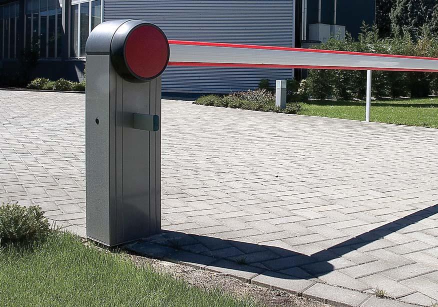
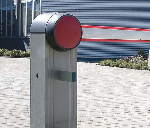
7 4. Standard installation 4 A i Ref. Code Description QIK4E Barrier cabinet QIK7EH Barrier cabinet 1 QIK7YEH Stainless steel barrier cabinet QIKZ Cabinet fastening base 2 3 QIKB37 QIKB50 QIKB60 QIKSN QIKBG QIKLUX QIKC QIKAM QIKGR QIKAF QIKAFE QIKAFZ Elliptical bar 3700 mm Elliptical bar 5000 mm Elliptical bar 6000 mm Articulated joint for elliptical bar Joint for elliptical bar Bar lighting kit Box of 10 bar reflectors Mobile support Aluminium skirt 2000 mm Fixed support Fixed support with electromagnetic block Fixed support fastening base 4 LAMPH Flashing XEL5 Key selector switch 5 LAN4 Combination keyboard LAN7 Card decoder XELCA Column for control accessories 6 GOL4 Remote control 7 XEL2 Photocells XELCB Photocell column 8 LAB9 Magnetic loop detector for passage control A Connect the power supply to a type-approved omnipolar switch, with a contact opening distance of at least 3 mm (not supplied). Connection to the mains must be via independent channel and separate from the connections to the control and safety devices. The given operating and performance features can only be guaranteed with the use of DITEC accessories and safety devices. 29
8 5. Dimensions = min max
9 6. Main components QIK4E QIK7EH QIK7YEH Ref. Code Description 1 24 V motor with encoder V~ motor 3 Mechanical stop adjustment 4 Key release 5 QIKM1 QIKM2 QIKM3 QIKM4 Grey spring Green spring Red spring Ø38 mm Red spring Ø51 mm 6 Control panel 7 Limit switch 8 Limit switch sliding block 31
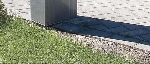
10 7. Mechanical installation Unless otherwise specified, all measurements are expressed in mm Ø60 Ø12, If the surface does not allow the cabinet to be fastened strongly and firmly, prepare a concrete base with embedded anchor ties and QIKZ base plate which must be level and clean. - Insert elements made of iron or another material in the anchor ties to attach the ties to the concrete reinforcement. - Pass the cable ducts through the central hole of the plate. WARNING: make sure that the fastening is strong and firm. - Secure the cabinet. i N.B.: to open the cabinet, release the automation as described on page 40 and unscrew the 4 screws on the front
11 8. Installation of bar L 1 2 only 4800mm Cut the length of the bar to L=+275 mm. - Install the bar as shown in the figure. 5 33
12 9. Bar balancing - Release the automation as described on page 40 and place the bar in the vertical opening position. - Place the spring in the correct position depending on the choice of opening direction as described on page Using the nuts placed above the spring (see ref. [B] on page 35), compress the spring until the bar is balanced at an angle of 5-30 to the floor (in this position, the bar must be stationary or point slightly upwards). WARNING: compression of the spring must comply with measurement A indicated on page Make sure that the bar remains still when in the open or closed position. WARNING: never use the force of the motor to support the weight of the bar. Always use the balancing spring. (mm) QIKM1 / / / QIKM1 / QIKM2 / / / QIKM2 / / / QIKM QIKM3 / / / QIKM3 / / QIKM4 / (mm) / / QIKM QIKM2 / / / QIKM2 / / / QIKM QIKM3 / / / QIKM3 / / QIKM4 / m min 500 (mm) / / QIKM QIKM3 / / m min 500 (mm) QIKM3 / / / QIKM3 / (mm) 2 m 2 m min / QIKM4 / WARNING: for 4000 mm, you must use the fixed support QIKAF-QIKAFE or the mobile support QIKAM. With the fixed support with the electromagnetic block QIKAFE installed, use the configurations indicated for the mobile support QIKAM. (mm) QIKM2 / / / QIKM2 / / / QIKM QIKM3 / / / QIKM3 / 34
13 10. Selecting opening direction A C B QIKM1 (grey) QIKM2 (green) QIKM3 (red Ø38) QIKM4 (red Ø51) A 190 mm 190 mm 220 mm 220 mm Right opening DIP2=OFF [E1A] DIP2A=OFF [EL31R] Left opening DIP2=ON [E1A] DIP2A=ON [EL31R] 85 Nm - Select the opening direction as shown in the figure. - Mount the spring using the special screw M12x40 [C] with thread locking compound and tightly fasten as shown in the figure. - [QIK4E] Set the DIP2 on the control panel E1A as shown in the figure. [QIK7EH] Set the DIP2A on the control panel EL31R as shown in the figure. - Once you have installed the bar, adjust spring compression using the nuts [B] until measurement A in the table is obtained. 35
14 11. Limit switch adjustment (QIK4E only) B A C A C - Adjust the opening and closing position of the bar using the special screws [A]. - Adjust the opening and closing limit switches using the special cams [C] so that the switches are activated approx. 3 mm before the mechanical stop [B]. 12. Electrical connections i N.B.: The electrical wiring and start-up of the gearmotors are shown in the control panel installation manuals. QIK4E Control panel E1A EL31R QIK7EH - QIK7YEH Before connecting the power supply, make sure the plate data correspond to that of the mains power supply. An omnipolar disconnection switch with minimum contact gaps of 3 mm must be included in the mains supply. Check that upstream of the electrical installation there is an adequate residual current circuit breaker and a suitable overcurrent cutout. Use a H05RN-F 3G1.5 or H05RR-F 3G1.5 type electric cable and connect it to terminals L (brown) and N (blue) inside the automation. Connect the earth wire. Connection to the mains power supply, in the section outside the automation, is made with independent channel and separated from the connections to the control and safety devices. The channel must penetrate the automation through the holes on the base plate at least 50 mm. Make sure there are no sharp edges that may damage the power supply cable. Make sure the mains power conductors (230 V) and accessory power conductors (24 V) are separated. 36
15 13. Routine maintenance plan Perform the following operations and checks every 6 months according to intensity of use of the automation. Disconnect the 230 V~ power supply and batteries (if present): - Clean and oil the levers and check the nuts and screws are all well tightened. - Clean and grease the articulated joint and spring-post as shown in the figure. - Check the electrical connections. - Check that the manual release is operating correctly. - Check that the bar is balanced correctly as shown on page [QIK4E] Check the capacity value of the motor condenser. - Check the state of wear of the mechanical parts, in particular the spring after about 300,000 work cycles. Reconnect the 230 V~ power supply and batteries if present: - [QIK4E] Make sure the limit switches are working correctly. - Check that obstacle detection is operating correctly. - Check that all control and safety functions are working correctly. i N.B.: For spare parts, see the spares price list. 37
16 38

17 Operating instructions General safety precautions DETACH AND DELIVER TO THE CUSTOMER These precautions are an integral and essential part of the product and must be supplied to the user. Read them carefully since they contain important information on safe installation, use and maintenance. These instructions must be kept and forwarded to all possible future users of the system. This product must only be used for the specific purpose for which it was designed. Any other use is to be considered improper and therefore dangerous. The manufacturer cannot be held responsible for any damage caused by improper, incorrect or unreasonable use. This product must not be used by people (including children) with reduced physical, sensorial or mental abilities, or lack of experience or knowledge, unless they are given proper surveillance and instructions for operating the device by a person responsible for their safety. Avoid operating in the proximity of the hinges or moving mechanical parts. Do not enter within the operating range of the motorised door while it is moving. Do not block the movement of the motorised door since this may be dangerous. Do not allow children to play or stay within the operating range of the motorised door. Keep remote controls and/or any other control devices out of the reach of children in order to avoid possible involuntary activation of the motorised door. In the event of a fault or a malfunction of the product, turn off the power supply switch, do not attempt to repair or intervene directly and contact only qualified personnel. Failure to comply with the above may cause a dangerous situation. All cleaning, maintenance or repair work must be carried out by qualified personnel. To ensure that the system works efficiently and correctly, the manufacturer s indications must be complied with and only qualified personnel must perform routine maintenance of the motorised gate. In particular, regular checks are recommended in order to verify that the safety devices are operating correctly. All installation, maintenance and repair work must be documented and made available to the user. To dispose of electrical and electronic equipment as well as batteries correctly, users must take them to special "recycling centres" provided by the municipal authorities. 39
18 Manual release instructions 1 2 In the event of a fault or power failure, insert the key, turn it anticlockwise and completely open the hatch. Manually open the barrier. To block the barrier again, close the hatch, turn the key clockwise and remove the key. WARNING: do not release with the springs under tension without bar. Perform bar locking and release with the motor switched off. Do not enter the operating range of the bar. When the barrier is released, the bar may move of its own accord. When the hatch is closed but the key is still horizontal, the release microswitch is open and all manoeuvres are prevented. To deactivate the barrier, the power supply must be removed and the batteries disconnected (if present). For any problems and/or information, contact the support service. Installer's stamp Operator Date of intervention Technician's signature Customer's signature DETACH AND DELIVER TO THE CUSTOMER Intervention performed Entrematic Group AB Lodjursgatan 10 SE , Landskrona Sweden 40
19 All the rights concerning this material are the exclusive property of Entrematic Group AB. Although the contents of this publication have been drawn up with the greatest care, Entrematic Group AB cannot be held responsible in any way for any damage caused by mistakes or omissions in this publication. We reserve the right to make changes without prior notice. Copying, scanning and changing in any way are expressly forbidden unless authorised in writing by Entrematic Group AB. 41
20 Entrematic Group AB Lodjursgatan 10 SE , Landskrona Sweden
Ditec QIK80EH Electromechanical barrier. IP2085EN Technical Manual. (Original instructions)
") Ditec QIK80EH Electromechanical barrier (Original instructions) IP2085EN Technical Manual www.ditecentrematic.com 2 Index Subject Page 1. General safety precautions 4 2. EC Declaration of Conformity 5
Ditec QIK80EH Electromechanical barrier (Original instructions) IP2085EN Technical Manual www.ditecentrematic.com 2 Index Subject Page 1. General safety precautions 4 2. EC Declaration of Conformity 5
QIK4E-QIK7EH. Installation and maintenance manual for electromechanical barrier. (Translation of the original instructions) IP1861EN- rev.
 IP1861EN- rev.") QIK4E-QIK7EH IP1861EN- rev. 2012-03-14 EN Installation and maintenance manual for electromechanical barrier. (Translation of the original instructions) DITEC S.p.A. Via Mons. Banfi, 3-21042 Caronno Pertusella
QIK4E-QIK7EH IP1861EN- rev. 2012-03-14 EN Installation and maintenance manual for electromechanical barrier. (Translation of the original instructions) DITEC S.p.A. Via Mons. Banfi, 3-21042 Caronno Pertusella
Ditec LUXO Swing gates automation (Original instruction)
") Ditec LUXO Swing gates automation (Original instruction) IP2128EN Technical manual www.ditecentrematic.com Index Subject Page 1. General safety precautions 21 2. Declaration of incorporation of partly
Ditec LUXO Swing gates automation (Original instruction) IP2128EN Technical manual www.ditecentrematic.com Index Subject Page 1. General safety precautions 21 2. Declaration of incorporation of partly
IP2160 EN. Ditec NEOS Sliding Gates. Technical Manual. (Original instructions)
") Ditec NEOS Sliding Gates (Original instructions) IP2160 EN Technical Manual www.ditecentrematic.com Index Subject Page 1. General safety precautions 4 2. Declaration of incorporation of partly completed
Ditec NEOS Sliding Gates (Original instructions) IP2160 EN Technical Manual www.ditecentrematic.com Index Subject Page 1. General safety precautions 4 2. Declaration of incorporation of partly completed
Ditec BOX Balanced up and over doors
 Ditec BOX Balanced up and over doors (original instructions) IP1529EN Technical Manual www.ditecentrematic.com All the rights concerning this material are the exclusive property of Entrematic Group AB.
Ditec CUBIC Swing gates automation
 Ditec CUBIC Swing gates automation (Original instructions) IP1812EN Technical Manual www.entrematic.com Index Subject Page 1. General safety precautions 21 General safety precautions for the user 22 2.
Ditec DOD Industrial sectional door automations
 Ditec DOD Industrial sectional door automations (Original instructions) IP1733EN Technical manual www.ditecentrematic.com Index Subject Page 1. General safety precautions 33 2. Declaration of incorporation
Ditec CROSS18-19 Sliding gates automation. IP1984 EN Technical Manual. (original instructions)
") Ditec CROSS18-19 Sliding gates automation (original instructions) IP1984 EN Technical Manual www.ditecentrematic.com 2 Index Subject Page 1. General safety precautions 4 2. Declaration of incorporation
Ditec CROSS18-19 Sliding gates automation (original instructions) IP1984 EN Technical Manual www.ditecentrematic.com 2 Index Subject Page 1. General safety precautions 4 2. Declaration of incorporation
Ditec VALOR Sliding doors automation (Original instructions)
") Ditec VALOR Sliding doors automation (Original instructions) IP1950 EN Technical manual www.entrematic.com Index Subject Page 1. General safety precautions 3 2. Declaration of incorporation of partly completed
Ditec VALOR Sliding doors automation (Original instructions) IP1950 EN Technical manual www.entrematic.com Index Subject Page 1. General safety precautions 3 2. Declaration of incorporation of partly completed
Ditec SPRINT Swing doors drive unit
 Ditec SPRINT Swing doors drive unit (Original instructions) IP2185 EN Technical Manual www.ditecentrematic.com Index Subject Page 1. General safety precautions 33 2. Declaration of incorporation of partly
Ditec PWR25H/35H Automation for hinged gates
 Ditec PWR25H/35H Automation for hinged gates (translation of the original instructions) www.entrematic.com IP2250EN Technical Manual Contents Subject Page 1. General safety precautions 27 2. Declaration
Ditec PWR50H/HV/HR Automation for swing gates
 Ditec PWR50H/HV/HR Automation for swing gates (translation of the original instructions) IP2253EN Technical Manual www.entrematic.com Contents Subject Page 1. General safety precautions 23 2. Declaration
Ditec VALOR HH-HS IP2063EN. Technical manual Sliding doors automation for hospitals and heavy sliding doors (Translation of the original instructions)
") IP2063EN Ditec VLOR HH-HS Technical manual Sliding doors automation for hospitals and heavy sliding doors (Translation of the original instructions) www.ditecentrematic.com Index Subject Page 1. General
IP2063EN Ditec VLOR HH-HS Technical manual Sliding doors automation for hospitals and heavy sliding doors (Translation of the original instructions) www.ditecentrematic.com Index Subject Page 1. General
IP2160EN. Ditec NeoS / NeoS+ Sliding Gates. Technical Manual. (Original instructions)
") Ditec NeoS / NeoS+ Sliding Gates (Original instructions) IP2160EN Technical Manual www.entrematic.com Contents Subject Page 1. General safety precautions 29 General safety precautions for the user 30 2.
Ditec NeoS / NeoS+ Sliding Gates (Original instructions) IP2160EN Technical Manual www.entrematic.com Contents Subject Page 1. General safety precautions 29 General safety precautions for the user 30 2.
Ditec EL31R Installation Manual for control panel for 24V automations with built-in radio.
 Ditec EL31R Installation Manual for control panel for 24V automations with built-in radio. IP1851EN Motor 24V= EL31R -M +M ENC A N T AT IN 11 JR1 ATK3 SA POWER 12 COM AUX SIG PRG Safety switch A 1 1 2
Entrematic Ditec Sprint 24V
 Foreløpig Brukerveiledning, vedlikeholdsog monteringsanvsing Entrematic Ditec Sprint 24V Ditec Sprint V Art.nr.: 2102200 Gewa AS Postboks 626 Trollåsveien 8 N-1411 KOLBOTN Tlf.: (+47) 66 99 60 00 Telefaks:
WEL. Manuale di installazione e manutenzione per automazioni per porte battenti. Installation and maintenance. for swing doors.
 WEL IP1891 - rev. 2007-04-20 I GB F D E P Manuale di installazione e manutenzione per automazioni per porte battenti. Installation and maintenance manual for automations for swing doors. Manuel d installation
Control panel installation manual for 230 V~ automation with one or two motors D5 S5 JT RF ON TC RP TR R1 OM J7. Electric lock. Flashing light.
 FUSE Ditec LOGIC M Control panel installation manual for 230 V~ automation with one or two motors IP1854EN LOGICM F2 FUSE JR4 JR10 SO D5 S5 JT NIO CT 1 2 3 4 5 RF ON AUX AUX F1 POWER SA IN 11 12 TM JR6
Ditec SPRINT Automation for swing doors
 Ditec SPRINT Automation for swing doors (translation of the original instructions) IP2185EN Technical Manual www.ditecentrematic.com 32 Contents Subject Page 1. General safety precautions 34 2. Declaration
INSTALLATION MANUAL FOR SWING SHUTTERS KAF212. FACE S.r.l. Viale delle Industrie, Dosson di Casier Treviso Italy
 INSTALLATION MANUAL FOR SWING SHUTTERS KAF212 FACE S.r.l. Viale delle Industrie, 74 31030 Dosson di Casier Treviso Italy INDEX Subject Page 1. General safety instruction 2 1.1 EC marking and European directives
Ditec E1A. IP2045EN Technical manual. Control panel installation manual for one motor automation with built-in radio.
 Ditec EA Control panel installation manual for one motor automation with built-in radio. EA RF FUSE CT 2 3 4 5 C O M SIG J2 PRG NIO F2 JR4 JR0 SO 6>4 IN JR3 R TC TM AUX A N T PT3 JR6 F FUSE 2 0 2 POWER
Ditec EL31R Installation Manual for control panel for 24V automations with built-in radio.
 Ditec EL31R Installation Manual for control panel for 24V automations with built-in radio. IP1851EN Motor 24V= EL31R -M +M ENC A N T BATK3 B A T IN 11 SA POWER 12 JR1 B COM AUX SIG PRG Safety switch A
INSTRUCTIONS FOR INSTALLATION
 HYDRAULIC OPERATOR MODO 110-110/L FOR SINGLE- OR DOUBLE-WING SWING GATES INSTRUCTIONS FOR INSTALLATION GENERAL WARNINGS These warnings constitute an integral and essential part of the product and must
EC MACHINE DIRECTIVE COMPLIANCE DECLARATION
 770 EC MACHINE DIRECTIVE COMPLIANCE DECLARATION (DIRECTIVE 89/392 EEC, APPENDIX II, PART B) Manufacturer: FAAC S.p.A. Address: Via Benini, 1 40069 - Zola Predosa BOLOGNA - ITALY Hereby declares that: the
EC MACHINE DIRECTIVE COMPLIANCE DECLARATION
 EC MACHINE DIRECTIVE COMPLIANCE DECLARATION (DIRECTIVE 89/392 EEC, APPENDIX II, PART B) Manufacturer: FAAC S.p.A. Address: Via Benini, 1 40069 - Zola Predosa BOLOGNA - ITALY Hereby declares that: the 770
Cross14, Cross14E, Cross14VE, Cross15V
 Cross14, Cross14E, Cross14VE, Cross15V IP1732 - rev. 2005-03- I GB F D E P Manuale di installazione e manutenzione per automazioni per cancelli scorrevoli. Installation and maintenance manual for sliding
24 V ENCODER SAFE VERSATILE SETTING. Ditec Qik Automatic barriers for passages up to 7.6 m.
 SAFE 24 V ENCODER VERSATILE SETTING EN Ditec Qik Automatic barriers for passages up to 7.6 m www.entrematic.com Ditec Qik Ditec Qik is the top performance automatic barrier that fits perfectly into any
USER INSTRUCTIONS FOR SLIDING DOORS
 ENGLISH USER INSTRUCTIONS FOR SLIDING DOORS SL3L LIGHT SL4A ADVANCED SL5A ADVANCED SL5H HEAVY SLTA TELESCOPIC-ADVANCED SL4E EMERGENCY SL5E EMERGENCY SL5B BIG SLTE TELESCOPIC-EMERGENCY FACE S.p.A. Viale
Typical Installation Schematic
 The 760 Gate Automation System The FAAC 760 automation system consists of a monoblock hydraulic unit and foundation box assembly. The system is designed for underground installation, and will not alter
Rex. Manuale di installazione e manutenzione per porte scorrevoli. Installation and maintenance manual for sliding door
 Rex IP1838 - rev. 2008-02-18 I GB F D E P Manuale di installazione e manutenzione per porte scorrevoli Installation and maintenance manual for sliding door Manuel d installation et d entretien pour portes
DOCUMENT TYPE = FITTING INSTRUCTIONS ORIGINAL LANGUAGE = ENGLISH. Maximum door weight = 40kg per leaf total system 80kg
 Evolve SIM Kit DOCUMENT TYPE = FITTING INSTRUCTIONS ORIGINAL LANGUAGE = ENGLISH 80kg Maximum door weight = 40kg per leaf total system 80kg Maximum door width 2 x 2mtr Track = 675-1058mm (Up to 2035 mm
SLIDE NEW CONTROL BOARD
 GB SLIDE NEW CONTROL BOARD CN1 CN2 3 4 5 FUSE 2 RL2 RL1 FUSE 1 TR2 TR1 TR3 TR4 U 1 JP1 Ld2 CMR 3 4 CN E Ld7 Ld6 Ld5Ld4Ld3 CN3 3 4 5 6 7 8 9 10 11 SW 12 13 14 Ld1 P2 P1 FUSE 1 FUSE 2 TR1 TR2 TR3 TR4 SW.1
BULL 424 ESA BULL 624 ESA
 L8542677 01/2012 rev 1 BULL 424 ESA BULL 624 ESA UNIONE NAZIONALE COSTRUTTORI AUTOMATISMI PER CANCELLI, PORTE SERRANDE ED AFFINI 1 140 260 92 83 330 330 210 326 2 X BULL.P3 34 mm = = 3 3 4 P P D 102 mm
Contents. EC DECLARATION OF CONFORMITY FOR MACHINES... p. 10. WARNINGS FOR THE INSTALLER... p. 10
 Contents EC DECLARATION OF CONFORMITY FOR MACHINES... p. 10 WARNINGS FOR THE INSTALLER... p. 10 1. DESCRIPTION AND TECHNICAL SPECIFICATIONS... p. 11 1.1. DIMENSIONS... p. 11 2. ELECTRIC DEVICES (standard
Maximum Weight = 80 kg for 2 doors; Maximum door width = 1100mm (to suit up to maximum 2120mm clear opening) Quick Start. 5 & 4mm Allen keys.
 Quick Start. 5 & 4mm Allen keys.") EVOLVE 80 SIM KIT FITTING INSTRUCTIONS - NOTICE DE POSE - MONTAGE HANDLEIDING - MONTAGEANLEITUNG ISTRUZIONI DI MONTAGGIO - INSTUCCIONES DE MONTAJE 80kg Maximum Weight = 80 kg for 2 doors; Maximum door
EVOLVE 80 SIM KIT FITTING INSTRUCTIONS - NOTICE DE POSE - MONTAGE HANDLEIDING - MONTAGEANLEITUNG ISTRUZIONI DI MONTAGGIO - INSTUCCIONES DE MONTAJE 80kg Maximum Weight = 80 kg for 2 doors; Maximum door
EC DECLARATION OF CONFORMITY FOR MACHINES (DIRECTIVE 98/37/EC) WARNINGS FOR THE INSTALLER
 WARNINGS FOR THE INSTALLER") EC DECLARATION OF CONFORMITY FOR MACHINES (DIRECTIVE 98/37/EC) Manufacturer: Address: Declares that: FAAC S.p.A. Via Benini, 1-40069 Zola Predosa BOLOGNA - ITALY 740-24V mod. operator is built to be integrated
EC DECLARATION OF CONFORMITY FOR MACHINES (DIRECTIVE 98/37/EC) Manufacturer: Address: Declares that: FAAC S.p.A. Via Benini, 1-40069 Zola Predosa BOLOGNA - ITALY 740-24V mod. operator is built to be integrated
Quick Start. Flat head screwdriver. Wheel carriage x 2. M8 Nut x 2. Strap Bolt x 2. 1 x 2m Anodised Track
 Evolve 80 Glass FITTING INSTRUCTIONS - NOTICE DE POSE - MONTAGE HANDLEIDING - MONTAGEANLEITUNG ISTRUZIONI DI MONTAGGIO - INSTUCCIONES DE MONTAJE 80kg Maximum Weight = 80kg - Maximum Door Width = 1100mm
AUTOMATION SYSTEM FOR SWING GATES FROG SERIES INSTALLATION MANUAL SUPERFROG
 AUTOMATION SYSTEM FOR SWING GATES FROG SERIES INSTALLATION MANUAL SUPERFROG IMPORTANT SAFETY INSTRUCTIONS FOR INSTALLATION CAUTION: IMPROPER INSTALLATION MAY CAUSE SERIOUS DAMAGE, FOLLOW ALL INSTALLATION
Automation Swing Gate Opener
 Automation Swing Gate Opener Operating and installation instructions SP EIFFEL 400 V1.0 Rev 08/01 CONTENTS 0) GENERAL SAFETY REGULATIONS...Page 0 1) DESCRIPTION...Page 03 ) TECHNICAL SPECIFICATIONS 3)
Automatic concealed bollards 275 H600 and 275 H800 with pit
 Automatic concealed bollards 275 H600 and 275 H800 with pit Technical installation manual CE Declaration of conformity Warnings for the installer Bollard technical data Preparing and installing the bollard
Installation Manual. Swing Gate System. Leading the way...
 Installation Manual 402 Swing Gate System Leading the way... Contents EC DECLARATION OF CONFORMITY FOR MACHINES... p. 2 WARNINGS FOR THE INSTALLER... p. 2 1. DESCRIPTION AND TECHNICAL SPECIFICATIONS...
Automatic concealed bollards 275 H600 and 275 H800 Control station
 Automatic concealed bollards 275 H600 and 275 H800 Control station Technical installation manual CE Declaration Warnings for the installer Bollard electrical connection Technical specifications for control
EC DECLARATION OF CONFORMITY
 EC DECLARATION OF CONFORMITY Manufacturer : Address: Declares that: FAAC S.p.A. Via Benini, 1-40069 Zola Predosa BOLOGNA - ITALY 844 T control board, conforms to the essential safety requirements of the
MOUNTING AND CONNECTING INSTRUCTIONS 1. GATE ARRANGEMENT ENGLISH
 SATURN SATURN is a motor reducer designed for the automation of sliding gates with grease lubrication of the gear in the 600 version; in oil bath in the 1000 and 2000 versions. The irreversibility of the
FORCE SPD 800/1500/2000
 English AUTOMATION SYSTEMS FOR SLIDING GATES Operating and installation instructions FORCE SPD 800/1500/2000 v1.0 Rev 11/2012 INDEX 1) General Safety Regulations... pág. 01 2) Description... pág. 02 3)
EC DECLARATION OF CONFORMITY FOR MACHINES WARNINGS FOR THE INSTALLER
 EC DECLARATION OF CONFORMITY FOR MACHINES (DIRECTIVE 2006/42/EC) Manufacturer: Address: Declares that: FAAC S.p.A. Via Benini, 1-40069 Zola Predosa BOLOGNA - ITALY 740 / 741 mod. operator is built to be
Cross Automations for sliding gates
 ENG Automations for sliding gates TM Advanced entrance technology Automations for sliding gates Sliding gates require flexible automations capable of managing different frame dimensions, different types
BULL 5M - BULL 5M.S BULL 8M - BULL 8 M.S BULL 8 OM - BULL 8 OM.S
 L8542676 04/2012 rev. 2 BULL 5M - BULL 5M.S BULL 8M - BULL 8 M.S BULL 8 OM - BULL 8 OM.S UNIONE NAZIONALE COSTRUTTORI AUTOMATISMI PER CANCELLI, PORTE SERRANDE ED AFFINI 1 140 260 100 91 330 330 210 326
UNDERGROUND OPERATOR FOR SWING GATES 119AS45EN. Installation manual FROG-A / FROG-AV / FROG-AE. English
 119AS45EN UNDERGROUND OPERATOR FOR SWING GATES Installation manual FROG-A / FROG-AV / FROG-AE English EN WARNING! important safety instructions: READ CAREFULLY! NECESSARY AND IN A VISIBLE PLACE SPECIAL
Nice TTN3724HS TTN3724RHS TTN6024HS TTN6024RHS
 Nice TTN3724HS TTN3724RHS TTN6024HS TTN6024RHS Swing gate opener EN - Instructions and warnings for installation and use CONTENTS GENERAL WARNINGS: SAFETY - INSTALLATION - USE 2 1 - PRODUCT DESCRIPTION
FITTING AND CONNECTION INSTRUCTIONS
 LEPUS is an oil-bathed motor-reducer created for sliding gates automation. The motor-reducer irreversibility allows a perfect and safe gate closing avoiding the setup of an electrolock and in case of power
BARRY BARRIER GATE AUTOMATION
 BARRY BARRIER GATE AUTOMATION Installation Manual 1. WARNINGS AND GENERAL SAFETY INSTUCTIONS This manual contains important safety information. An incorrect installation or an improper use may cause serious
Installation manual ASTER AUTOMATION FOR SWING GATES 11_16
 Installation manual ASTER AUTOMATION FOR SWING GATES 11_16 Contents 1. GENERAL SAFETY PRECAUTIONS... page 01 2. INTENDED USE AND APPLICATION... page 01 2.1 Kit contents... page 01 2.2 Technical features...
1 GENERAL SAFETY PRECAUTIONS
 16EN 16 1 GENERAL SAFETY PRECAUTIONS Failure to respect the information given in this manual may cause personal injury or damage to the device. This installation manual is intended for qualified personnel
IRREVERSIBLE OPERATOR FOR SWING GATES AND DOORS
 VH IRREVERSIBLE OPERATOR FOR SWING GATES AND DOORS WARNING!! Before installing, thoroughly read this manual that is an integral part of the pack Our products if installed by qualified personnel capable
UNDERGROUND OPERATOR FOR SWINGING GATES. WARNING!! Before installing, thoroughly read this manual that is an integral part of the pack
 UNDERGROUND OPERATOR FOR SWINGING GATES COMPAS 2 WARNING!! Before installing, thoroughly read this manual that is an integral part of the pack Our products if installed by qualified personnel capable to
CE DECLARATION OF MACHINE CONFORMITY
 CE DECLARATION OF MACHINE CONFORMITY (DIRECTIVE 2006/42/EC) Manufacturer : Address: Declares that: FAAC S.p.A. Via Calari, 10-40069 Zola Predosa BOLOGNA - ITALY Operator mod. 541 3ph is built to be incorporated
CICLÓN ATTUATORE ELETTROMECCANICO IRREVERSIBILE A BRACCIO SNODATO PER CANCELLI A BATTENTE
 by IL n. 366 EDIZ. 28/03/2012 CICLÓN I GB F E P D ATTUATORE ELETTROMECCANICO IRREVERSIBILE A BRACCIO SNODATO PER CANCELLI A BATTENTE IRREVERSIBLE ELECTROMECHANICAL PIVOTING ARM ACTUATOR FOR SWING GATES
D Vers. 03 ELECTROMECHANICAL AUTOMATION FOR SWING GATES
 E5 D811007 15-09-99 Vers. 03 ELECTROMECHANICAL AUTOMATION FOR SWING GATES 122 This product complies with recognised technical standards and safety regulations. We declare that this product is in conformity
Sheet n 1 of 20 Doc. n WDMM/02/E MOD. WDMM INSTALLATION, USE AND SERVICE MANUAL. PETROL INSTRUMENTS S.r.l APRILIA (LT) - ITALY
 - ITALY") Sheet n 1 of 20 WATER DRAW/ MASTER METER PETROL COUNTER MOD. WDMM INSTALLATION, USE AND SERVICE MANUAL PETROL INSTRUMENTS S.r.l. - 04011 APRILIA (LT) - ITALY Sheet n 2 of 20 INSTALLATION, USE AND SERVICE
Sheet n 1 of 20 WATER DRAW/ MASTER METER PETROL COUNTER MOD. WDMM INSTALLATION, USE AND SERVICE MANUAL PETROL INSTRUMENTS S.r.l. - 04011 APRILIA (LT) - ITALY Sheet n 2 of 20 INSTALLATION, USE AND SERVICE
JOINT INSTALLATION MANUALS AND SAFETY INFORMATION
 INSTALLATION MANUALS AND SAFETY INFORMATION SEA S.p.A. Zona industriale 64020 S.ATTO Teramo - (ITALY) Tel. +39 0861 588341 r.a. Fax +39 0861 588344 www.seateam.com seacom@seateam.com REV.00-06/2016 1 TABLE
L /2012 rev 0 BISON 45 OTI UNIONE NAZIONALE COSTRUTTORI AUTOMATISMI PER CANCELLI, PORTE SERRANDE ED AFFINI
 L8542965 03/2012 rev 0 BISON 45 OTI UNIONE NAZIONALE COSTRUTTORI AUTOMATISMI PER CANCELLI, PORTE SERRANDE ED AFFINI 1 470 327 F A 500 825 B 243.5 2 C 445 210 15 ±5 205 92 50 2 3 4 I D2 D2 D1 5 T 6 D A
VEM motors Thurm GmbH
 VEM motors Thurm GmbH Installation, Operating and Maintenance Instructions Single-Phase Squirrel-Cage Induction Motors, Standard Version March 2005 1. General To avoid damage to the motors and equipment
INDEX CE DECLARATION OF CONFORMITY FOR MACHINES... 2 WARNINGS FOR THE INSTALLER DESCRIPTION AND TECHNICAL SPECIFICATIONS...
 INDEX CE DECLARATION OF CONFORMITY FOR MACHINES... 2 WARNINGS FOR THE INSTALLER... 2 1. DESCRIPTION AND TECHNICAL SPECIFICATIONS... 3 1.1 MAXIMUM USE CURVE... 4 2 ELECTRIC PREPARATIONS (standard system)...
Corso Principi di Piemonte, 65/ RACCONIGI (CN) ITALY tel fax
 ITALY tel fax") V2 S.p.A. Corso Principi di Piemonte, 65/67 12035 RACCONIGI (CN) ITALY tel. +39 01 72 81 24 11 - fax +39 01 72 84 050 info@v2home.com - www.v2home.com IL n.131 EDIZ. 28/08/2012 Bingo I GB F E P D NL ATTUATORE
V2 S.p.A. Corso Principi di Piemonte, 65/67 12035 RACCONIGI (CN) ITALY tel. +39 01 72 81 24 11 - fax +39 01 72 84 050 info@v2home.com - www.v2home.com IL n.131 EDIZ. 28/08/2012 Bingo I GB F E P D NL ATTUATORE
EC DECLARATION OF CONFORMITY FOR MACHINES (DIRECTIVE 98/37/EC)
") EC DECLARATION OF CONFORMITY FOR MACHINES (DIRECTIVE 98/37/EC) Manufacturer: Address: Declares that: FAAC S.p.A. Via Benini, 1-40069 Zola Predosa BOLOGNA - ITALY The operator mod. 844 R Reversible is built
EC DECLARATION OF CONFORMITY FOR MACHINES (DIRECTIVE 98/37/EC) Manufacturer: Address: Declares that: FAAC S.p.A. Via Benini, 1-40069 Zola Predosa BOLOGNA - ITALY The operator mod. 844 R Reversible is built
Installation manual. English. mystrike OPENER FOR RACK-DRIVEN SLIDING MOTOR
 Installation manual English mystrike OPENER FOR RACK-DRIVEN SLIDING MOTOR 1. WARNINGS AND GENERAL SAFETY INSTRUCTIONS This manual contains important safety information. An incorrect installation or an
Sectional and Tilting Door Opener
 Sectional and Tilting Door Opener Installation Instructions and User Guide 600 800 1000 S/N WARNING Please read the manual carefully before installation and use. The installation of your new door opener
Qik. Automatic Barriers. Advanced entrance technology ENG
 TM ENG Qik Automatic Barriers Advanced entrance technology Looking for a parking access solution? Qik is your answer Truly innovative shapes and uncompromising safety: these are the credentials of the
MEKO OPENER FOR RACK-DRIVEN SLIDING MOTOR
 Installation Manual MEKO OPENER FOR RACK-DRIVEN SLIDING MOTOR 02_2016 1. WARNINGS AND GENERAL SAFETY INSTUCTIONS This manual contains important safety information. An incorrect installation or an improper
E R A I GATE AUTOMATION DIVISION
 S E R A I GATE AUTOMATION DIVISION INSTALLATION MANUAL MC/5C - 03.5C UNDERGROUND MOTOR 230 Vac FOR WING GATES UP TO 3,00m AND 300 Kg EACH WING + FOUNDATION BOX IN HOT-GALVANISED STEEL Thank you for choosing
L /2013 rev 0 BISON 35 OTI UNIONE NAZIONALE COSTRUTTORI AUTOMATISMI PER CANCELLI, PORTE SERRANDE ED AFFINI
 L8543019 04/2013 rev 0 BISON 35 OTI UNIONE NAZIONALE COSTRUTTORI AUTOMATISMI PER CANCELLI, PORTE SERRANDE ED AFFINI 1 458 250 A F 645 477 B 195 470 270 2 C 13 ±5 156 70 2 3 4 D2 R D2 I D1 T 5 W D H G R
L /2012 rev 0 BISON 30 OTI UNIONE NAZIONALE COSTRUTTORI AUTOMATISMI PER CANCELLI, PORTE SERRANDE ED AFFINI
 L8542968 07/2012 rev 0 BISON 30 OTI UNIONE NAZIONALE COSTRUTTORI AUTOMATISMI PER CANCELLI, PORTE SERRANDE ED AFFINI 1 458 250 A F 645 477 B 195 470 270 2 C 13 ±5 156 70 2 3 4 D2 R D2 I D1 T 5 W D H G R
Mod: KLD6-12/35XLAS-N
 12/2011 Mod: KLD6-12/35XLAS-N Production code: 1914070 INSTRUCTION MANUAL LOGIC LINE PLUS HOOD Reseller Stamp for Warranty Dear customer, Above all, thank you for choosing our product and we would like
BAYT 980. Oil-hydraulic OIL-HYDRAULIC BARRIER FOR TRAFFIC CONTROL INSTALLATION MANUAL. code 4425 Post with fixing base. POLO 44 - optional -
 Oleodinamica BAYT 980 Oil-hydraulic OIL-HYDRAULIC BARRIER FOR TRAFFIC CONTROL POLO 44 - optional - BAYT 980 560 code 4425 Post with fixing base the gate opener Made in Italy INSTALLATION MANUAL GB INSTRUCTIONS
Sectional and Tilting Door Opener Installation Instructions and User Guide
 Sectional and Tilting Door Opener Installation Instructions and User Guide ET-600E ET-800E ET-1000E S/N WARNING Please read the manual carefully before installation and use. The installation of your new
GROUND GROUND - ( ) Interrati elettromeccanici ISTRUZIONI PER L INSTALLAZIONE. Electromechanical underground INSTRUCTIONS FOR INSTALLATIONS
 Interrati elettromeccanici ISTRUZIONI PER L INSTALLAZIONE. Electromechanical underground INSTRUCTIONS FOR INSTALLATIONS") GROUND GROUND - (610-624) Interrati elettromeccanici ISTRUZIONI PER L INSTALLAZIONE Electromechanical underground INSTRUCTIONS FOR INSTALLATIONS I UK F E D P NL GR 2 GROUND 1a 6 3 4 7 Ø 5 x4 3 9 1 8 1
GROUND GROUND - (610-624) Interrati elettromeccanici ISTRUZIONI PER L INSTALLAZIONE Electromechanical underground INSTRUCTIONS FOR INSTALLATIONS I UK F E D P NL GR 2 GROUND 1a 6 3 4 7 Ø 5 x4 3 9 1 8 1
IN-GROUND OPERATOR FOR SWING GATES FROG SERIES INSTALLATION MANUAL FROG-A 230V
 IN-GROUND OPERATOR FOR SWING GATES FROG SERIES INSTALLATION MANUAL FROG-A 230V IMPORTANT INSTALLATION, SAFETY INSTRUCTIONS CAUTION: IMPROPER INSTALLATION MAY CAUSE SERIOUS DAMAGE, FOLLOW ALL INSTALLATION
ECO PLUS RAPID DOOR USER S AND INSTALLER S MANUAL
 ECO PLUS RAPID DOOR USER S AND INSTALLER S MANUAL v1.0 REV. 02/2018 00. CONTT 01. SAFETY INSTRUCTIONS INDEX 01. SAFETY INSTRUTIONS STANDARDS TO FOLLOW 02. THE AUTOMATISM COMPONTS TECHNICAL SPECIFICATIONS
OPERATING AND USERS MANUAL
 OPERATING AND USERS MANUAL EN Automatic battery chargers 12V10A 399000 PF.09272 12V15A 399010 PF.09273 12V25A 399020 PF.09274 12V40A 399030 PF.09275 24V20A 399040 PF.10284 WARNING BEFORE OPERATION THIS
BELT CONVEYOR CB/M5 Series
 BELT CONVEYOR CB/M5 Series User and maintenance manual 1 DECLARATION OF CONFORMITY The company: Tel. +39-0444 450 620-451 520 Fax +39-0444 671 840 declares under its own responsibility that the machine
Table of Contents. General Safety Preparation for Installation Parts List Optional Accessories Part List... 5
 REV 12a Table of Contents General Safety....... 2 Preparation for Installation....... 3 Parts List....... 4 Optional Accessories Part List...... 5 Technical Specifications & Feature...... 5 Installation
BL240 BL240 - (15400) Operatore elettromeccanico lineare ISTRUZIONI PER L INSTALLAZIONE
 Operatore elettromeccanico lineare ISTRUZIONI PER L INSTALLAZIONE") - (15400) Operatore elettromeccanico lineare ISTRUZIONI PER L INSTLLZIONE Electromechanical linear operator INSTRUCTIONS FOR INSTLLTIONS I UK F E D P NL GR 2 1a 5 8 10 7 4 10 1 3 2 B 5 8 9 9 6 1b 9 1 2
- (15400) Operatore elettromeccanico lineare ISTRUZIONI PER L INSTLLZIONE Electromechanical linear operator INSTRUCTIONS FOR INSTLLTIONS I UK F E D P NL GR 2 1a 5 8 10 7 4 10 1 3 2 B 5 8 9 9 6 1b 9 1 2
BELT CONVEYOR PNL/4 Series User and maintenance manual
 BELT CONVEYOR PNL/4 Series User and maintenance manual 1 DECLARATION OF CONFORMITY CE In conformity with the 2006/42/CE Machine Directives, Enclosure II, section A The company: VIRGINIO NASTRI S.r.l. Tel.
PW320/PW330 USER MANUAL SWING GATE OPENERS 24V DC GEAR MOTOR FOR RESIDENTIAL. Flashing Light. Push Button. Control box. Gate 2.
 PW320/PW330 USER MANUAL SWING GATE OPENERS 24V DC GEAR MOTOR FOR RESIDENTIAL Flashing Light Push Button Control box Gate 2 Gate 1 Declaration of Conformity Applicant: Powertech Electronics Inc. Manufacturer:
AUTOMATION FOR STREET BARRIERS GARD 8 SERIES INSTALLATION MANUAL G G2080I
 AUTOMATION FOR STREET BARRIERS GARD 8 SERIES INSTALLATION MANUAL G2080 - G2080I IMPORTANT SAFETY INSTRUCTIONS FOR INSTALLATION CAUTION: IMPROPER INSTALLATION MAY CAUSE SERIOUS DAMAGE, FOLLOW ALL INSTALLATION
GB Instructions Manual
 GB Instructions Manual pages - 8 CMYK- 0 0 KYMC- 0 0 KYMC- 0 0 0 KYMC- 8 KYMC- 0 KYMC- 0 0 0 KYMC- 0 0 0 0 Underground oil-hydraulic operator for swinging gates or 7 shaft rotation Compact all-in-one oil-hydraulic
BISON 20 OM BISON 25 OTI
 L8542939 11/2011 rev 0 BISON 20 OM BISON 25 OTI UNIONE NAZIONALE COSTRUTTORI AUTOMATISMI PER CANCELLI, PORTE SERRANDE ED AFFINI 2 x 1,5 GND 13 8 7 5 RG 58 4 3 4 x 0,35 6 1 2 4 3 x 1,5 min 230V 2 x 0,35
SLIDE & OL USER'S AND INSTALLER'S MANUAL V1.0 REV. 06/2017
 SLIDE & OL USER'S AND INSTALLER'S MANUAL V1.0 REV. 06/2017 00. CONTT 01. SAFETY INSTRUCTIONS INDEX 01. SAFETY INSTRUCTIONS STANDARDS TO FOLLOW 02. OPERATOR TECHNICAL SPECIFICATIONS DESCRIPTION DIMSIONS
SARGON S - M - L. All rights reserved INSTALLATION MANUAL
 INSTALLATION MANUAL Our compliments for your excellent choice. SARGON LINE S (300mm) M (400mm) and L (600mm) electro-mechanical gear motor has been produced for reliability and high quality. This Manual
IMPORTANT NOTICE FOR THE INSTALLER
 EC MACHINE DIRECTIVE COMPLIANCE DECLARATION (DIRECTIVE 89/392 EEC, APPENDIX II, PART B) Manufacturer: FAAC S.p.A. Address: Via Benini, 1 40069 - Zola Predosa BOLOGNA - ITALY Hereby declares that: the 6
Porte 150 Users Manual Swing Gate Opener 24V DC
 Porte 150 Users Manual Swing Gate Opener 24V DC for residential use only Signal Light Push-button Control Box 14 Contents 1. Important Safety Information 2. Product Description and Application 2.1 Application
INSTALLATION MANUAL ENGLISH ALPHA 200 ALPHA 330. L C (stroke) 960 mm 1160 mm
 960 mm 1160 mm") INSTLLTION MNUL The LPH is provided with a mechanical locking system that grants the operator locking in the opened and closed position avoiding any needs for electric locks and/or magnetic locks. The
INSTLLTION MNUL The LPH is provided with a mechanical locking system that grants the operator locking in the opened and closed position avoiding any needs for electric locks and/or magnetic locks. The
OPERATION & MAINTENANCE INSTRUCTIONS
 AUTOMATIC BATTERY CHARGER / MAINTAINER MODEL NO: CBO9-12 PART NO: 6267025 OPERATION & MAINTENANCE INSTRUCTIONS LS0315 INTRODUCTION Thank you for purchasing this CLARKE product. Before attempting to use
OMATION FOR SLIDING GATES LINESTAR INSTALLATION MANUAL
 AUTOMA OMATION FOR SLIDING GATES LINESTAR INSTALLATION MANUAL CONTENTS 1.0 Description of the system parts page 3 1.1 Description of the parties of the group gearmotor page 3 2.0 General characteristics
CO 3-WAY PNEUMATIC VALVE INSTRUCTION MANUAL 2080
 CO 3-WAY PNEUMATIC VALVE INSTRUCTION MANUAL 2080 STI S.r.l has taken every care in collecting and verifying the documentation contained in this Instruction Manual. The information herein contained are
INSTALLER AND USER S MANUAL. v4.0 REV. 01/2019
 MBM6 -BARRIER INSTALLER AND USER S MANUAL v4.0 REV. 01/2019 00. CONTT INDEX 01. SAFETY INSTRUCTIONS STANDARDS TO FOLLOW 01. SAFETY INSTRUCTIONS STANDARDS TO FOLLOW 02. PACKAGE INSIDE PACKAGE 03. OPERATOR
OPERATION & MAINTENANCE INSTRUCTIONS
 AUTOMATIC BATTERY CHARGER / MAINTAINER MODEL NO: CBO9-6/12 PART NO: 6267020 OPERATION & MAINTENANCE INSTRUCTIONS LS0615 INTRODUCTION Thank you for purchasing this CLARKE product. Before attempting to use
ASW-400. Installation Manual. Downee
 ASW-400 Installation Manual Downee INDEX INDEX 2 TECHNICAL DATA 3 OVERALL DIMENSIONS 4 SET PANEL 5 MAINTENANCE DISPOSAL FINAL RECOMMENDATIONS THIS HANDBOOK IS APPOINTED FOR THE INSTALLER ONLY The installation
PW150/PW200 USER MANUAL SWING GATE OPENERS 24V DC GEAR MOTOR
 PW150/PW200 USER MANUAL SWING GATE OPENERS 24V DC GEAR MOTOR FOR RESIDENTIAL Flashing Light Push Button Control box Declaration of Conformity Applicant: Powertech Electronics Inc. Manufacturer: Timotion