.RESEARCH.MEMORANDUM. WASHINGTON April 6,1955. By Powell M. Lovell, Jr. Langley Aeronautical Laboratory Langley Field, Va.
|
|
|
- Hugo Higgins
- 5 years ago
- Views:
Transcription
1 .RESEARCH.MEMORANDUM i FLIGHT TESTS OF A DELTA-WING VERTICALLY RISING AIRPLANE MODEL POWEFIED BY A DUCTED FAN By Powell M. Lovell, Jr... Langley Aeronautical Laboratory Langley Field, Va.. ~. This material contains information affect- ule National Defense of the Unlted States wlthin the meanlng of the espionage laws, Title 18, U.S.C., Secs. 193 and 784, the tr8a5mhslon or revelatloo of which in any mwer to an unauthorized person is prohibited by law.,....,...,., " NATIONALADVISORY COMMITTEE FOR AERONAUTICS WASHINGTON April 6,1955
2 I I NACA RM L55B17 C r, 1 NATIONAL ADVISORY COMMITTEE AEXONAUTICS FOR msearch MEMORANDUM FLIGHT TESTS OF A DELTA-WING VERTICALLY RISING AIRF'LANE MODEL POWEEED BY A DUCTED FAN By Powell M. Lovell, Jr. SUMMARY An experimental investigation has been conducted to determine the dynamic stability and control characteristics of a delta-wing vertically rising airplane model powered by a ducted fan. In addition to conventional flap-type control surfaces on the wings and vertical tail, the model had jet-reaction control provided bymovable eyelids at the rear of the tail pipe and by air bled from the main duct and exhausted through movable nozzles near the wing tips. The investigation included take-offs and landings, hovering flight, and the transition from hovering to unstalled forward flight. In hovering flight, the model could be fl& smoothly and easily without any automatic stabilization. The jet-reaction controls were powerful and enabled the pilots to maneuver the model rapidly to various positions within the hovering test area. Take-offs could be made easily and landings on a predetermined spot could be made accurately. About half the transition flights made without automatic stabilization devices were unsuccessful because the model diverged in roll and yaw at angles of attack between about 50 and 60 despite the efforts of the pilots to stop it. In some cases, however, it was possible to make the transition when the model happened to be flying very steadily as it passed through the critical angle-of-attack range. The use of artificial damping in roll greatly improved the lateral stability and made the model easy to fly throughout the entire speed range. The use of artificial damping in yaw, directional stability, or dihedral effect, however, did not provide sufficient improvement in the critical angle-of-attack range to eliminate the occurrence of divergences during the transition.
3 2 INTRODUCTION An investigation has been conducted to determine the dynamic stability and control characteristics of a jet-powered delta-wing vertically rising airplane model. A ducted-fan powerplant was used because there was no hot-jet powerplant of sufficiently small size and adequate reliability available. When the test results are interpreted, it should be borne in mind that the gyroscopic effects which a jet engine may have on the stability and control characteristics of a vertically rising airplane were not simulated because the two motors of the model powerplant turned in opposite directions and the gyroscopic forces were canceled. The investigation consisted entirely of flight tests and covered take-offs and landings, hovering flight, and the transition from hovering to unstalled forward flight. In the transition flights, which covered a range of angle of attack from about 90' to loo, the effects of various artificial lateral-stability devices were determined. The results of the investigation were obtained both from the pilots' observations and opinions of the stability and controllability of the model and from time histories of the motions of the model prepared from motion-picture records of the flights. NOMENCLATURE AND SYMBOLS In order to avoid confusion in terminology which might arise because of the large range of operating attitudes of the model, it should be explained that the controls and motions of the model are referred to in conventional terms relative to the body system of axes; that is, the rudder on the vertical tail and the deflection of the jet to left or right by the eyelid produced yaw about the no& body axis; differential deflection of the elevons and the jet nozzles in the wing produced roll about the fuselage axis; and simultaneous up or down deflections of the elevons and deflection of the jet up or down by the eyelid produced pitch about the spanwise axis. Figure 1 shows the axes and the positive directions of the linear and angular displacements. I e The symbols used in the present paper are as follows: angle pitch of of fuselage axis relative to horizontal, deg (For this report the angle of attack and angle of pitch are the same.) angle of yaw, positive for right yaw; measured from the vertical in plane shown by rear camera, deg angle of bank, deg -
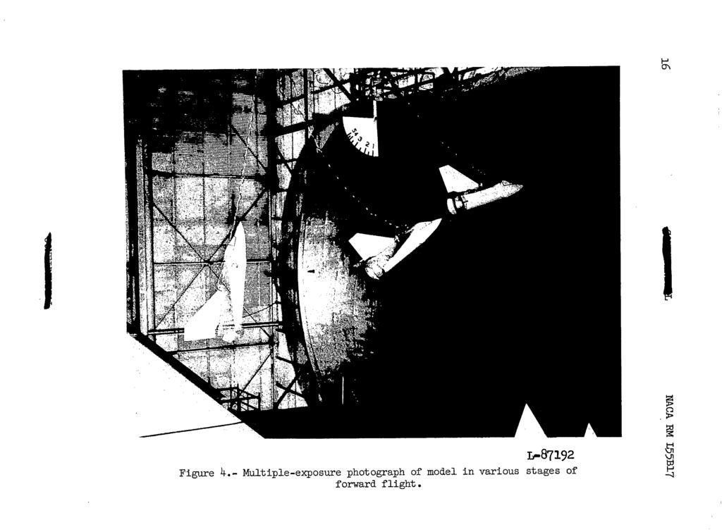
4 3 t 6a Sr 6e sec time, deflection of controls to produce roll control deflection of controls to produce yaw control deflection of controls to produce pitch control APPARA!T'US AND TESTS Model Photographs of the model showing the pmerplant installation and controls are presented as figure 2, and a sketch showing some of the more important dimensions is shown as figure 3. The geometric characteristics of the model are presented in table I. A multiple-exposure photograph showing the model in various stages of a transition flight is presented as figure 4. The model was powered by two 5-horsepower electric motors turning inch-diameter oppositely rotating propellers in a duct 4 feet long. The duct was made of cellular plastic 0.25 inch thick covered both inside and outside with laminated-glass-fiber fabric. A rounded lip was provided on the forward end of the duct to increase the static thrust of the ducted fan. It is not known exactly howmuch increase was provided by this lip but tests of another ducted fm indicate than an increase in thrust of 60 percent over that of a ducted fan with a sharp lip might be expected. The model had modified delta-wing and vertical-tail surfaces with conventional flap-type elevon and rudder controls for use in forward flight. Pitch and yaw controls for hovering flight were provided by eyelids at the rear of the fuselage which deflected the jet. Roll control was provided by air routed from the main duct through the wings to differentially moving nozzles near the wing tips. About 10 percent of the air was bled off from the main duct to the nozzles. In most flights, the jet-reaction controls were operated by the flicker-type (full-on or off) pneumatic actuators used on all models by the Langley free-flight tunnel section. These actuators were equipped with an integrating-type trimer which trimmed the control a small amount in the direction the control was moved each time a control deflection was applied. With actuator,s of this type, a model becomes accurately trimmed after flying a short time in a given flight condition.
5 4 NACA RM L55B17 In some of the transition flights, various artificial stabilizing devices were used to move the controls automatically in proportion to the rate of roll, rate of yaw, or to the sideslip angle. The sensing elements for the rate-of-roll and rate-of-yaw devices were rate gyroscopes which, in response to rate of roll or rate of yaw, provided signals to proportional control actuators which moved the controls to oppose the 'rolling or yawing motion. A pilot-operated override was provided in the gyroscope-operated devices so that the pilot could have all the available control power at his command.the operation of these devices was such that they provided damping in roll or yaw regardless of the attitude of the model. The override cut out the damping action and applied all available control in the direction desired by the pilot. If there had not been an override, the damping devices would have applied controls to oppose those applied by the pilot and would thus reduce the control effectiveness available to the pilot. The sensing elements for the angle-ofsideslip stabilizing devices were air-flow valves operated by a vane mounted on a boom extending from the nose of the model which provided signals to the proportional control actuators that moved the controls in response to an angle of sideslip. Inasmuch as only a small amount of excess thrust was available, it was necessary to keep the weight of the model to a minimwn to avoid overheating of the electric-drive motors. In some cases, therefore, various items of equipment unnecessary for a given test were removed. For the take-off, hovering, and landing tests, the flap-type control actuators were removed; for the transition tests, the landing-gear shock struts were removed. The weight of the model for the transition tests was 45.2 pounds and for the take-off, landing, and hovering tests, was 46.5 pounds. Test Equipment and Setup The take-off, landing, and hovering tests were conducted in a large building which provided protection from the random effects of outside air currents and thereby permitted the basic stability and control characteristics of the model to be determined more readily. The forward-flight tests were conducted in the Langley full-scale tunnel. Essentially the same test setup was used in all tests. This setup is illustrated for the forward-flight tests in figure 5. The sketch shows the pitch pilot, the safety-cable operator, and a power and camera operator on a balcony at the side of the test section. The roll pilot was located in an enclosure in the lower rear part of the test section, and the yaw pilot and a second camera operator were at the top rear of the test section. The three pilots were located at positions which gave them a good vantage point for observing and controlling the particular phase of the motion with which they were concerned. In the hovering
6 L tests, which were made in a different facility, the pilots and operators were also stationed at various positions around the test area to give them a good vantage point for observing and flying the model. A safety cable was used for catching the model to prevent crashes in case of a parer or control failure or in the event that the pilots lost control of the model. This cable was attached to the top of the fuselage at the front motor mount and was then run over a pulley at the ceiling of the test chamber and to the safety-cable operator who adjusted the length of the cable to keep it slack during flight. Thepower and control cable consisted of plastic tubes, which provided air for the electro-pneumatic control actuators, and electric wires, which supplied power for the motors and carried the remote control signals to the control actuators. This cable was led from the power sources and suspended from the ceiling from a point near the safety cable pulley. It was then taped to the safety cable from about 15 feet above the model down to the model. Tests The investigation consisted of flight tests to determine the stability and control characteristics of the model in vertical take-offs and landings in still air, in hovering flight in still air, and in forward flight. The test results were obtained both from the pilots' observations and opinions of the behavior of the model and from motionpicture records of the motions of the model. In take-offs, landings, and hovering flight, the eyelids were deflected 24.O from the trim position for both yaw and pitch control and the roll nozzles were deflected 260~. For forward flight, the eyelids were deflected fllo for elevator control and f8' for rudder control and the roll nozzles were deflected 260~. In all the forward-flight tests, the elevons were deflected +18O for roll control. In the few forward- flight tests in which the elevons and rudder were used for longitudinal and directional control, the elevons were deflected fl3' and the rudder was deflected t18o. The take-off tests were made by increasing the power to the model fairly rapidly until it took off. After the take-off, power was reduced until the model stabilized at a height of about 10 feet above the ground. Landing tests were started with the model in steady hovering flight at a height of about 10 feet above the ground. The power was reduced slightly so that the model descended slowly until the landing gear was about 6 inches above the ground. At this point the power was cut off abruptly and the model dropped to the ground.
7 ~ " 6 NACA RM L52B17 The hovering-flight tests were made at a height of about 15 to 20 feet above the ground in order to study the basic stability and control characteristics of the model when it was high enough to eliminate any possible effects of ground proximity. In these tests the ease with which the model could be flown in steady hovering flight and maneuvered from one position to another was studied. The transition-flight tests were started with the model in hovering flight in the test section of the full-scale tunnel and, as the airspeed was increased, the controls were operated so that the model tilted progressively into the wind to maintain its fore-and-aft position in the test section. These flights corresponded to very slow constant-altitude transitions and covered a range of angle of attack from the hovering attitude of about 830 to an angle of attack of about 10'. Since small corrections or adjustments to the tunnel airspeed could not bemade quickly, the pitch pilot and power operator had to make adjustments continually in order to hold the model in the center of the test section. Flights were also made in which the airspeed was held constant at intermediate speeds so that the stability and control characteristics at constant speeds could be studied. Constant speeds less than 25 miles per hour could not be maintained, however, because of speed control limitations in the drive system of the Langley full-scale tunnel. Artificial stability devices which provided damping in roll, damping in yaw, effective dihedral, and directional stability were used one at a time in the tests. The control surfaces were moved approximately 3O per degree per second for the damping parameters and 3' per degree of sideslip for the directional stability and effective dihedral parameters. The exact amount of each of the stability parameters added artificially is not known because no force tests have been made to determine the control effectiveness. RESULTS AND DISCUSSION The results of the investigation are illustrated more graphically by motion pictures of the flights of the model than is possible in a written presentation. For this reason a motion-picture film supplement to this paper has been prepared and is available on loan from the National Advisory Committee for Aeronautics, Washington, D. C. When the test results are interpreted, it should be borne in mind that the gyroscopic effects which - a jet engine may have on the stability and control characteristics of a vertically rising airplane were not simulated because the two motors of the model powerplant turned in opposite directions and the gyroscopic forces were canceled.
8 NACA RM L55B17 7 Basic Model Hovering flight.- The model could be flown smoothly and easily in hovering flight and could be maneuvered to any desired position at will. Figure 6 shows time histories of three typical flights in which the model takes off, maneuvers away from the take-off position, hovers a short time, maneuvers back to the take-off position, and lands. The jet-reaction controls provided good controllability and, as is evident in the time histories, the model could be moved fairly rapidly from one position to another and restored quickly to a steady-flight condition. The motions of the model in pitch and yaw were very steady. Since the stability was not studied in detail, it is not known whether the model had unstable pitching and yawing oscillations such as had been experienced previously with propeller-driven models. It was clear, however, that the model did not tend to start an oscillation as quickly as the propellerdriven models and was consequently easier for the pilots to fly. The rolling motions, as would be expected, seemed about neutrally stable. The modelseemed easier to fly in roll than the propeller-driven models previously tested because the random torque fluctuations which had been experienced with the unshrouded propellers of propeller-driven models were much less severe with the shrouded propellers of the present model. Take-offs and landings. - Take-off s could be made very easily; in fact, they were easier to perform than for any of the propeller-driven vertically rising airplane models tested by the Langley free-flight tunnel section. The time histories of figure 6 show that the model took off vertically with very little control required. For all these take-offs, the controls were trimed for hovering flight before the start of the tests. The take-offs were smoother when the angle (pitch or yaw) at which the model rested on the ground was the same as the angle for hovering flight. Occasionally, because of improper inflation of the pneumatic shock struts, these angles were not identical and the model would slide sideways about one-half a span before leaving the ground. This sideways motion could not be stopped by use of the controls until the model left the ground. It was not particularly objectionable to the pilots but it did cause them to have,to maneuver the model back to the desired flight path. The climb to thf hovering altitude appeared rougher than for those take-offs in which the angle at which the model rested on the ground was the same as the angle for hovering flight. The model could be landed fairly gently on a predetermined spot on the ground with little difficulty. No decrease in stability or controllability was noticed when the model neared the ground.

9 8 Forward flight.- The forward flights made in the test section of the Laagley full-scale tunnel which represented slow, constant-altitude transitions covered a range of angle of attack from about 90' down to loo. Some preliminary flights were made with both the jet-reaction controls and the flap-type controls operating for roll, pitch, and yaw. These tests showed that for the high-speed portion of the transition the use of both sets of control resulted in excessive control moments and consequently in overcontrolling. Al later flights were therefore made with only the eyelids operating for yaw and pitch controls. Both the nozzles and elevons were used for roll control, however, because it was found that the nozzles alone did not provide sufficient rolling moment for control at the angles of attack at which the tendency toward the rolling and yawing divergence was encountered. About half the forward flights made without automatic-stabilization devices were unsuccessful because the model diverged in roll and yaw at angles of attack between about.50 and 60 despite the efforts of the pilots to stop it. In all cases, the divergence started with the model rolling to the left about 20' or 30, flying in a sideslipped attitude for a short time, and then diverging in yaw to the right. Figure 7 shows time histories of two transition flights which ended in such dlvergences. Since no accurate records of the rolling motions could be obtained from the motion pictures, these time histories are somewhat incomplete but they do illustrate the difficulty of controlling the motions since, at the time of the divergence, the control records indicate that the pilots were holding corrective control (right aileron and left rudder) as the model diverged. The roll records presented are only approximate. Their only purpose is to indicate the time at which the model started the rolling divergence. The divergence could not be studied in detail because of speed-control limitations in the Langley full-scale tunnel. Theminimum steady airspeed available was 25 miles per hour which corresponded to an angle of attack of 33O; thus, when the airspeed reached the minimum steady-state value, the model had already passed through the critical angle-of-attack range. The reasons for the divergence have not yet been definitely ascertained but some of the factors which probahly contribute to the divergence are known. A rapid change in roll trim between hovering and low-speed forward flight existed which may have been caused by asymmetry in the model or by a change in propeller torque due to increased inflow velocity as the model went into forward flight. The divergence in roll was undoubtedly aggravated by this change in roll trim, which caused difficulty in controlling the model - because the pilot could not trim the controls quickly enough. Another contributing factor to the divergence might have been the negative dihedral effect. If the model possessed negative effective dihedral at these high angles of attack, any sideslip introduced by control deflections or by rolling of the model about its body axis would have caused it to tend to diverge in roll. The divergence in yaw following the roll could have been caused by static directional instability.
10 Force tests of a similar model have indicated the likelihood directional instability at very high angles of attack. of static In some cases it was possible to complete the transition if the model happened to be flying very steadily as it passed through the critical angle-of-attack range in which the strong divergent tendency was encountered and if this critical range was passed through rapidly. Figure 8 shows a time history of a transition flight in which there was no divergence. Although this yaw record indicates that the model did not fly very smoothly in yaw at the higher speeds, the 'yaw pilot felt that the model was easy to control in this speed range. In the unstalled flight range, the lateral motions of the model were easy to control and in most cases the roll pilot could quit controlling the model and the yaw pilot alone could control the lateral motions. The model tended to wander but the yaw pilot could stop it at any time he desired. The lateral motions could not be controlled satisfactorily with the roll controls alone in the unstalled flight range because of the adverse aileron yawingmoments. The pitch and power controls were somewhat difficult to coordinate since variations in thrust also changed the pitching moment because the center of gravity was not on the thrust axis. Despite the coordination difficulty, however, the model could be flown smoothly in pitch at the higher speeds. At times the model seemed to have stability of angle of attack since, at constant tunnel airspeeds, it could be flown hands-off occasionally for a short period of time without any indication of a tendency to diverge. Effect of Artificial Stabilizing Devices Roll damper.- The roll damper which moved the elevons greatly improved the stability in both the critical angle-of -attack range (50' to 60 ) and at high speeds so that all the transition flights attempted with this device installed were successful. Apparently the roll damper reduced the tendency of the model to sideslip by keeping it steady in roll about the body axis. During the high-speed portions of these flights, the roll pilot had to apply very little control; in fact, the record of figure 9 shows that the roll pilot did not have to apply any control after the model reached angles of attack below about 50'. The flights with the roll damper installed were much smoother than for any other condition covered in the investigation. Theyaw record is similar to that made without any automatic stabilization but, in this case, the. roll and yaw pilots,;found that, although a.slight tendency to diverge was still evldent, the model could be controlled fairly easily fn the critical angleof-attack range. The roll pilot was able.to trim the model for level flight early in the flight and then could stop flying the model and let
11 10 the yaw pilot alone control the lateral motions at high speeds. This procedure was followed in most of the flights because of the excessive roll control at high speeds. Yaw damper. - When the yaw damper with a manual override was used to operate the yaw eyelid and the rudder was held fixed, the tendency toward a lateral divergence in the low-speed portion of the transition was reduced somewhat but was not eliminated. The model sometimes diverged at angles of attack of about 50 to 60 in spite of the pilot's.efforts to control it. At high speeds the flights were much smoother than whenno automatic stabilization was used. Apparently the stability of the Dutch-roll motion was increased by the yawdamper to such an extent that the motion was not excited so easily by the roll and yaw controls. The use of the yawdamper operating the rudder (no override was used in this system) and mual control of the yaw eyelid did not cause any noticeable improvement in the divergent tendency during the low-speed portion of the transition, probably because of low rudder effectiveness in this high angle-of-attack range. The flights were smoother at high speeds, however, than whe no automatic stabilization was used. This improvement at high speeds apparently resulted from the increase in damping of the Dutch-roll motion provided by the damper. Artificial dihedral effect.- Additional effective dihedral was provided by a vane pick-up operating a proportional-control actuator which deflected the elevons differentially when the model sideslipped. No override was provided in this control system and the roll pilot had manual control only of the nozzles. With this system in operation, the lateral divergence in the transition range was not materially improved and the behavior at high speeds was mademuch worse than whenno automatic stabilization was used. The flights were characterized by rolling oscillations between about f20 angle of bank. At high speeds these oscillations became violent and were very difficult to control. Usually the oscillations at high speeds caused loss of control and the model had to be retrieved with the safety cable. Artificial directional stability.- Additional directional stability was provided by the vane pick-up operating a proportional control actuator connected to the rudder. No override.was provided with this system and the yaw pilot had manual control only of the yaw eyelid. The lateral divergent tendency at low speeds was not materially improved, probably because the vertical tail and rudder were blanketed by the wing so that the rudder was relatively ineffective. This system reduced the yaxing motions at high speeds but it caused the rolling oscillation to become very pronounced at high speeds as was the case when artificial dihedral effect was used.
12 SUMMARY OF RESULTS The results of a free-flight investigation of the stability and control characteristics of a delta-wing vertically rising airplane model poweredby a ducted fan can be summarized as follows: 1. In hovering flight the model could be flam smoothly and easily without any automatic stabilization devices. The jet-reaction controls were powerful and enabled the pilots to maneuver the model to various positions within the hovering test area and to restore it to a steadyflight condition rapidly. 2. Take-offs could be made easily and landings on a predetermined spot could be made accurately. 3. The eyelid controls provided good pitch and yaw control throughout the entire speed range covered in the investigation. In order to maintain roll control in the transition range, however, the jet-reaction roll control had to be supplemented by the flap-type elevons. 4. Transition flights without automatic stabilization were difficult to accomplish because of a lateral divergence which occurred between angles of attack of about 50' to 60. Only about half the forward flights without automatic stabilization were successful. 5. The use of a roll damper eliminated the lateral divergent tendency during the low-speed portion of the transition and also made the high-speed portion of the flights much smoother than in any other test condition. The use of artificial damping in yaw, directional stability, or dihedral effect, however, did not provide sufficient improvement in the critical angle-of-attack range to eliminate the occurrence of divergences during transition flights. Langley Aeronautical Laboratory, National Advisory Committee for Aeronautics, Langley Field, Va., February 2, 1955.
13 I, TABLE I.- GEOMETRIC CHARACTERISTICS OF MODEL Weight. lb Hovering. take.offs. and landings Forward flight Wing (modified tri-a,r plan form): Sweepback. deg Airfoil section... NACA 65~006 Aspect ratio Taper ratio (rooto tip) kea. sq in span. in Mean aeroaynamic chord. in Span of elevon. in Chord of elevon. in Span of roll-control nozzles. in Chord of roll-control nozzles. in Overall length of model. in f om) : deg Airfoil section... &A 65AOO6 Aspect ratio Taper ratio (root to tip) 2.94 Area. sq in Span. in... Span of rudder. in Vertical tail (modified triangular plan Sweepback. Chord of rudder. in... Fuselage : Duct length. in Inside diameter. in Outside diameter. in "..."......
14 Figure 1.- The body system of axes. Arrows indicate positive directions of linear and angular displacements.

15 v NACA RM L55B17
16 1- I 25 4 I Figure 3.- Sketch showing the more important dimensions. are in inches. All dimensions
17 Y

18 Figure 5.- Sketch of test setup for forward flight.
19 18., - NACA RM L35B ) E % 6.0 U - E 4:O o I.O Figure 6.- Time histories of take-offs, hovering flights, in still air. and landings."".."_ ".,,.,,,,
20 IO. c =* 6.0 0, : 4 n P 6 s o - Figure 6. Continued.
21 20 - C NACA RM L55B17 Left Yaw control I. I I I I I l l I Rlght UP Pitch control I I I I I I II till I I. I I Down Tme, sec Figure 6.- Concluded.
22 I NACA RM ~ 55~17 rrr, 21 ~oll control Rlght Le' - Rol I Left control Rlght Yaw control Left " 1 Right Yaw control ~" t kf Rlght Pltch control Down 01 I L -20 -I0 8o r I0 8o I 2ok L OO A Time, sec 601"\7i\J\ 8,deg O O L"d&d Ttme sec Figure 7.- Time histories of transition flights made without automatic stabilization that ended in lateral divergences. The roll records are only approximate and merely indicate when the rolling divergence started.
23 Left II II I Ilf II 111 I I1 I I I I I I IIIII Roll control Rlgh+ I u n NII JIIIII II 1111 I I II II I 1111 II Iu Iu 60 t v A I I I I I I I I l l 1 I I 1 I l l I I l l I l l u E Tlme,t,sec Gl u Figure 8.- Time history of a transition flight made without automatic w P stabilization and in which there was no lateral divergence. ;I
24 z?- 0 Left? Rdl contrd Right I ~11111 s I IO I- [\ 0 l l l l l l 1 l l l I I I I I I I ) Tlme,t,sec Figure 9.- Time history of a transition flight made with a roll damper installed.
RESEARCH MEMORANDUM. fox the. U. S. Air Force
 RESEARCH MEMORANDUM fox the U. S. Air Force - NACA RM SL53L24 NATIONAL ADVISORY COMMITTEE FOR AERONAIJTICS RESEARCH "ORANDUM the for U. S. Air Force _.I SPEED-BRAKE INVESTIGATION AT LOW SPEEDOF A l/lo-scale
International Journal of Scientific & Engineering Research, Volume 4, Issue 7, July ISSN BY B.MADHAN KUMAR
 International Journal of Scientific & Engineering Research, Volume 4, Issue 7, July-2013 485 FLYING HOVER BIKE, A SMALL AERIAL VEHICLE FOR COMMERCIAL OR. SURVEYING PURPOSES BY B.MADHAN KUMAR Department
Weight & Balance. Let s Wait & Balance. Chapter Sixteen. Page P1. Excessive Weight and Structural Damage. Center of Gravity
 Page P1 Chapter Sixteen Weight & Balance Let s Wait & Balance Excessive Weight and Structural Damage 1. [P2/1/1] Airplanes are designed to be flown up to a specific maximum weight. A. landing B. gross
XIV.C. Flight Principles Engine Inoperative
 XIV.C. Flight Principles Engine Inoperative References: FAA-H-8083-3; POH/AFM Objectives The student should develop knowledge of the elements related to single engine operation. Key Elements Elements Schedule
RESEARCH MEMORANDUM NATIONAL ADVISORY COMMITTEE FOR AERONAUTICS. By John A. Ramen and George R. Gray w. WASHINGTON August 7, 1951
 ! RESEARCH MEMORANDUM TANK NVESTGATON OF THE GRUMMAN JRF-5 ARPLANE WTH A SNGLE HYDRO-SK AND AN'EXTENDED AFTERBODY By John A. Ramen and George R. Gray w Of NATONAL ADVSORY COMMTTEE FOR AERONAUTCS WASHNGTON
Prop effects (Why we need right thrust) Torque reaction Spiraling Slipstream Asymmetric Loading of the Propeller (P-Factor) Gyroscopic Precession
 Torque reaction Spiraling Slipstream Asymmetric Loading of the Propeller (P-Factor) Gyroscopic Precession") Prop effects (Why we need right thrust) Torque reaction Spiraling Slipstream Asymmetric Loading of the Propeller (P-Factor) Gyroscopic Precession Propeller torque effect Influence of engine torque on aircraft
Prop effects (Why we need right thrust) Torque reaction Spiraling Slipstream Asymmetric Loading of the Propeller (P-Factor) Gyroscopic Precession Propeller torque effect Influence of engine torque on aircraft
Section 2: Basic Aerobatics
 Section 2: Basic Aerobatics Airplane Considerations and Control Setup Primary to Aerobatic Airplane Transition Parallel Positioning B-34 Basic Aerobatics Introduction Aerobatics is unarguably the most
Flightlab Ground School 13. A Selective Summary of Certification Requirements FAR Parts 23 & 25
 Flightlab Ground School 13. A Selective Summary of Certification Requirements FAR Parts 23 & 25 Copyright Flight Emergency & Advanced Maneuvers Training, Inc. dba Flightlab, 2009. All rights reserved.
Lecture 5 : Static Lateral Stability and Control. or how not to move like a crab. G. Leng, Flight Dynamics, Stability & Control
 Lecture 5 : Static Lateral Stability and Control or how not to move like a crab 1.0 Lateral static stability Lateral static stability refers to the ability of the aircraft to generate a yawing moment to
XIV.D. Maneuvering with One Engine Inoperative
 References: FAA-H-8083-3; POH/AFM Objectives The student should develop knowledge of the elements related to single engine operation. Key Elements Elements Schedule Equipment IP s Actions SP s Actions
Design Considerations for Stability: Civil Aircraft
 Design Considerations for Stability: Civil Aircraft From the discussion on aircraft behavior in a small disturbance, it is clear that both aircraft geometry and mass distribution are important in the design
Performance means how fast will it go? How fast will it climb? How quickly it will take-off and land? How far it will go?
 Performance Concepts Speaker: Randall L. Brookhiser Performance means how fast will it go? How fast will it climb? How quickly it will take-off and land? How far it will go? Let s start with the phase
CHAPTER 11 FLIGHT CONTROLS
 CHAPTER 11 FLIGHT CONTROLS CONTENTS INTRODUCTION -------------------------------------------------------------------------------------------- 3 GENERAL ---------------------------------------------------------------------------------------------------------------------------
Lateral Directional Flight Considerations
 Lateral Directional Flight Considerations This section discusses the lateral-directional control requirements for various flight conditions including cross-wind landings, asymmetric thrust, turning flight,
AERONAUTICAL ENGINEERING
 AERONAUTICAL ENGINEERING SHIBIN MOHAMED Asst. Professor Dept. of Mechanical Engineering Al Ameen Engineering College Al- Ameen Engg. College 1 Aerodynamics-Basics These fundamental basics first must be
All Credit to Jeff Goin and Scout Paramotoring
 TechDummy Understanding Paramotor Torque & Twist ad how to correct or minimize Mar 18, 2013 Section IV Theory & Understanding See other PPG Bible Additions See also Paramotor Torque Twist and Crash Torque
Climber is 776B101101
 is Climber 776B101101 Introduction Product Introduction NE R/C 776B is a good-sized glider designed by Nine Eagles Company latest, whose wing span is up to 2008mm. You only need to assemble the aerofoil
FLASHCARDS AIRCRAFT. Courtesy of the Air Safety Institute, a Division of the AOPA Foundation, and made possible by AOPA Services Corporation.
 AIRCRAFT FLASHCARDS Courtesy of the Air Safety Institute, a Division of the AOPA Foundation, and made possible by AOPA Services Corporation. Knowing your aircraft well is essential to safe flying. These
Initial / Recurrent Ground Take-Home Self-Test: The Beechcraft 58 Baron Systems, Components and Procedures
 Initial / Recurrent Ground Take-Home Self-Test: The Beechcraft 58 Baron Systems, Components and Procedures Flight Express, Inc. This take-home self-test partially satisfies the recurrent ground training
FLIGHT TEST PROGRAM YOUR AIRPLANE HERE FLIGHT TEST PROGRAM YOUR AIRPLANE HERE
 Flight #: 1 FIRST TEST FLIGHT Validate Engine Reliability Explore Flight Control Characteristics Do not use flaps Do not change throttle settings, mixture, or fuel tanks Remain above the airport Climb
Die Lösungen müssen manuell überpüft werden. Die Buchstaben stimmen nicht mehr überein.
 HELI Final Test 2015, Winterthur 17.06.2015 NAME: Mark the best answer. A B C D A B C D Die Lösungen müssen manuell überpüft werden. Die Buchstaben stimmen nicht mehr überein. 1 1 Principles of Flight
Cessna Aircraft Short & Soft Field Takeoff & Landing Techniques
 Cessna Aircraft Short & Soft Field Takeoff & Landing Techniques Objectives / Content For short- and soft-field takeoff and landing operations in CAP Cessna aircraft, review: Standards (from ACS) Procedures
UNCLASSIFIED i34l AD ARMED SERVICES TECHNICAL INFORMATION AGENCY ARLINGTON HALL STATION ARLINGTON 12, VIRGINIA UNCLASSIFIED
 UNCLASSIFIED 2 6-8i34l AD 268342 ARMED SERVICES TECHNICAL INFORMATION AGENCY ARLINGTON HALL STATION ARLINGTON 12, VIRGINIA L UNCLASSIFIED NOTICE: When governent or other drawings, specifications or other
DESIGN FOR SPIN. Leonardo Manfriani Pilatus Aircraft Ltd. Keywords: aerodynamic design, rotary balance testing, flight mechanics, spinning
 DESIGN FOR SPIN Leonardo Manfriani Pilatus Aircraft Ltd. Keywords: aerodynamic design, rotary balance testing, flight mechanics, spinning Abstract The Pilatus PC-21 advanced turboprop trainer was designed
52 BACKYARDFLYER.COM FLY
 52 BACKYARDFLYER.COM FLY HELIS IN1O EASY STEPS by Klaus Ronge Photography by Hope McCall & Pete Hall Flying model helicopters is exciting and fun and looks very easy, that is, until you try it. Unlike
SIMULATION OF PROPELLER EFFECT IN WIND TUNNEL
 SIMULATION OF PROPELLER EFFECT IN WIND TUNNEL J. Červinka*, R. Kulhánek*, Z. Pátek*, V. Kumar** *VZLÚ - Aerospace Research and Test Establishment, Praha, Czech Republic **C-CADD, CSIR-NAL, Bangalore, India
Flight Stability and Control of Tailless Lambda Unmanned Aircraft
 IJUSEng 2013, Vol. 1, No. S2, 1-4 http://dx.doi.org/10.14323/ijuseng.2013.5 Editor s Technical Note Flight Stability and Control of Tailless Lambda Unmanned Aircraft Pascual Marqués Unmanned Vehicle University,
INDEX. Preflight Inspection Pages 2-4. Start Up.. Page 5. Take Off. Page 6. Approach to Landing. Pages 7-8. Emergency Procedures..
 INDEX Preflight Inspection Pages 2-4 Start Up.. Page 5 Take Off. Page 6 Approach to Landing. Pages 7-8 Emergency Procedures.. Page 9 Engine Failure Pages 10-13 Propeller Governor Failure Page 14 Fire.
FLIGHT CONTROLS SYSTEM
 FLIGHT CONTROLS SYSTEM DESCRIPTION Primary flight control of the aircraft is provided by aileron, elevator and rudder control surfaces. The elevator and rudder control surfaces are mechanically operated.
DUCHESS BE-76 AND COMMERCIAL MULTI ADD-ON ORAL REVIEW FOR CHECKRIDE
 DUCHESS BE-76 AND COMMERCIAL MULTI ADD-ON ORAL REVIEW FOR CHECKRIDE The Critical Engine The critical engine is the engine whose failure would most adversely affect the airplane s performance or handling
Turbinator-2 Build Manual
 Turbinator-2 Build Manual Thank you for your purchase of the Turbinator-2 sport jet by Boomerang RC Jets. This RC Jet IS NOT A TOY and should only be flown and operated by experienced RC Turbine Pilots.
Introduction. Fuselage/Cockpit
 Introduction The Moravan Zlin 242L is a fully aerobatic 2 seat aircraft designed to perform all advanced flight maneuvers within an envelope of -3.5 to +6 Gs. Many military and civilian flight-training
Chapter 3: Aircraft Construction
 Chapter 3: Aircraft Construction p. 1-3 1. Aircraft Design, Certification, and Airworthiness 1.1. Replace the letters A, B, C, and D by the appropriate name of aircraft component A: B: C: D: E: 1.2. What
It has taken a while to get
 HOVERING15 99 15 BASICS HOVERING Hovering It has taken a while to get here, but this is what all the building and planning were for to see light under those skids. But this is also the time when you have
Cause of AA587 A R
 Another Possible Cause of AA587 A300-605R Accident July 18, 2005 This brief report is prepared to explain the possibility that the inertial forces on the control linkages moved control surfaces, or at
1.1 REMOTELY PILOTED AIRCRAFTS
 CHAPTER 1 1.1 REMOTELY PILOTED AIRCRAFTS Remotely Piloted aircrafts or RC Aircrafts are small model radiocontrolled airplanes that fly using electric motor, gas powered IC engines or small model jet engines.
Caution Notes. Features. Specifications. Installation. A3 3-axis Gyro & Stabilizer User Manual V1.0
 Caution Notes Thank you for choosing our products. If any difficulties are encountered while setting up or operating it, please consult this manual first. For further help, please don t hesitate to contact
31 st Annual American Helicopter Society Student Design Competition: Graduate Submission
 Rotorcraft Adaptive and Morphing Structures Lab The Emperor UAV: Executive Summary George Jacobellis Alex Angilella Jean-Paul Reddinger Andrew Howard Matthew Misiorowski Michael Pontecorvo Jayanth Krishnamurthi
64MM F-16 Fighting Falcon V2
 64MM F-16 Fighting Falcon V2 SIMPLE Simple assembly RIGID STRONG DURABLE EPO STABLE SMOOTH FLYING PERFORMANCE FMSMODEL.COM Table of Contents Introductions 3 Contents of Kit 4 Assemble the plane 5 Battery
Gyroplane questions from Rotorcraft Commercial Bank (From Rotorcraft questions that obviously are either gyroplane or not helicopter)
") Page-1 Gyroplane questions from Rotorcraft Commercial Bank (From Rotorcraft questions that obviously are either gyroplane or not helicopter) "X" in front of the answer indicates the likely correct answer.
Page-1 Gyroplane questions from Rotorcraft Commercial Bank (From Rotorcraft questions that obviously are either gyroplane or not helicopter) "X" in front of the answer indicates the likely correct answer.
Reducing Landing Distance
 Reducing Landing Distance I've been wondering about thrust reversers, how many kinds are there and which are the most effective? I am having a debate as to whether airplane engines reverse, or does something
AIRCRAFT DESIGN MADE EASY. Basic Choices and Weights. By Chris Heintz
 AIRCRAFT DESIGN MADE EASY By Chris Heintz The following article, which is a first installement of a two-part article, describes a simple method for the preliminary design of an airplane of conventional
CHECKLIST 1969 CESSNA 172-K. NOTE: Verify all information with airplane's POH
 CHECKLIST 1969 CESSNA 172-K NOTE: Verify all information with airplane's POH PRE-FLIGHT INSPECTION 1 CABIN 1 A.R.R.O.W. CHECK Airworthiness Cert. In Clear View Registration In Clear View Radio License
UNITED STATES OF AMERICA CIVIL AERONAUTICS BOARD WASHINGTON, D.C.
 UNITED STATES OF AMERICA CIVIL AERONAUTICS BOARD WASHINGTON, D.C. Civil Air Regulations Amendment 4b-2 Effective: August 25, 1955 Adopted: July 20, 1955 AIRPLANE AIRWORTHINESS - TRANSPORT CATEGORIES MISCELLANEOUS
How to use the Multirotor Motor Performance Data Charts
 How to use the Multirotor Motor Performance Data Charts Here at Innov8tive Designs, we spend a lot of time testing all of the motors that we sell, and collect a large amount of data with a variety of propellers.
The Airplane That Could!
 The Airplane That Could! Critical Design Review December 6 th, 2008 Haoyun Fu Suzanne Lessack Andrew McArthur Nicholas Rooney Jin Yan Yang Yang Agenda Criteria Preliminary Designs Down Selection Features
AIRCRAFT DESIGN SUBSONIC JET TRANSPORT
 AIRCRAFT DESIGN SUBSONIC JET TRANSPORT Analyzed by: Jin Mok Professor: Dr. R.H. Liebeck Date: June 6, 2014 1 Abstract The purpose of this report is to design the results of a given specification and to
Fokker 50 - Landing Gear & Flaps
 FLIGHT CONTROLS The flight controls can be operated manually and automatically. From the flight deck, all control surfaces are mechanically operated via rod-and-cable systems, except the electrically operated
IMPACT REGISTER, INC. PRECISION BUILT RECORDERS SINCE 1914
 IMPACT REGISTER, INC. PRECISION BUILT RECORDERS SINCE 1914 RM-3WE (THREE WAY) ACCELEROMETER GENERAL The RM-3WE accelerometer measures and permanently records, for periods of 30, 60, and 90 days, the magnitude,
System Normal Secondary Direct. All 3 PFC work in parallel. available. Pitch Normal Secondary Direct. Pitch maneuver command.
 Flight s System Normal Secondary Direct Primary Flight Computers (PFC) Three Primary Flight Computers use control wheel and pedal inputs from the pilot to electronically the primary flight control surfaces
Aeroelasticity and Fuel Slosh!
 Aeroelasticity and Fuel Slosh! Robert Stengel, Aircraft Flight Dynamics! MAE 331, 2016 Learning Objectives Aerodynamic effects of bending and torsion Modifications to aerodynamic coefficients Dynamic coupling
U.S. NAVAL TEST PILOT SCHOOL FLIGHT TEST MANUAL
 USNTPS-FTM-No. 103 U.S. NAVAL TEST PILOT SCHOOL FLIGHT TEST MANUAL FIXED WING STABILITY AND CONTROL Theory and Flight Test Techniques Approved for public release; distribution is unlimited. NAVAL AIR WARFARE
Metrovick F2/4 Beryl. Turbo-Union RB199
 Turbo-Union RB199 Metrovick F2/4 Beryl Development of the F2, the first British axial flow turbo-jet, began in f 940. After initial flight trials in the tail of an Avro Lancaster, two F2s were installed
Charles H. Zimmerman promoted his Flying Pancake design from 1933 to 1937 while working for the
 Model Number : V-173 Model Name : Flying Pancake Model Type: Proof of Concept, Fighter Charles H. Zimmerman promoted his Flying Pancake design from 1933 to 1937 while working for the National Advisory
Full-Scale 1903 Wright Flyer Wind Tunnel Test Results From the NASA Ames Research Center
 Full-Scale 1903 Wright Flyer Wind Tunnel Test Results From the NASA Ames Research Center Henry R. Jex, Jex Enterprises, Santa Monica, CA Richard Grimm, Northridge, CA John Latz, Lockheed Martin Skunk Works,
Appenidix E: Freewing MAE UAV analysis
 Appenidix E: Freewing MAE UAV analysis The vehicle summary is presented in the form of plots and descriptive text. Two alternative mission altitudes were analyzed and both meet the desired mission duration.
DEVELOPMENT OF A CARGO AIRCRAFT, AN OVERVIEW OF THE PRELIMINARY AERODYNAMIC DESIGN PHASE
 ICAS 2000 CONGRESS DEVELOPMENT OF A CARGO AIRCRAFT, AN OVERVIEW OF THE PRELIMINARY AERODYNAMIC DESIGN PHASE S. Tsach, S. Bauminger, M. Levin, D. Penn and T. Rubin Engineering center Israel Aircraft Industries
LAA TYPE ACCEPTANCE DATA SHEET TADS 193 RANS S4 AND RANS S5 (B WING AND C WING)
") Issue 2 MOD/193/006 added, ref tail bracing wire tang cracking. dated 13.06.07 1. UK contact Skycraft Ltd., Kestrel, Broadgate, Weston Hills, Spalding. Lincs. PE12 6DP. United Kingdom Telephone: 01406
Issue 2 MOD/193/006 added, ref tail bracing wire tang cracking. dated 13.06.07 1. UK contact Skycraft Ltd., Kestrel, Broadgate, Weston Hills, Spalding. Lincs. PE12 6DP. United Kingdom Telephone: 01406
Facts, Fun and Fallacies about Fin-less Model Rocket Design
 Facts, Fun and Fallacies about Fin-less Model Rocket Design Introduction Fin-less model rocket design has long been a subject of debate among rocketeers wishing to build and fly true scale models of space
Airframes Instructor Training Manual. Chapter 6 UNDERCARRIAGE
 Learning Objectives Airframes Instructor Training Manual Chapter 6 UNDERCARRIAGE 1. The purpose of this chapter is to discuss in more detail the last of the Four Major Components the Undercarriage (or
Y. Lemmens, T. Benoit, J. de Boer, T. Olbrechts LMS, A Siemens Business. Real-time Mechanism and System Simulation To Support Flight Simulators
 Y. Lemmens, T. Benoit, J. de Boer, T. Olbrechts LMS, A Siemens Business Real-time Mechanism and System Simulation To Support Flight Simulators Smarter decisions, better products. Contents Introduction
Flight Test Evaluation of C-130H Aircraft Performance with NP2000 Propellers
 Flight Test Evaluation of C-130H Aircraft Performance with NP2000 Propellers Lance Bays Lockheed Martin - C-130 Flight Sciences Telephone: (770) 494-8341 E-Mail: lance.bays@lmco.com Introduction Flight
Van s Aircraft RV-7A. Pilot s Operating Handbook N585RV
 Van s Aircraft RV-7A Pilot s Operating Handbook N585RV PERFORMANCE SPECIFICATIONS SPAN:..25 0 LENGTH...20 4 HEIGHT:.. 7 10 SPEED: Maximum at Sea Level...180 knots Cruise, 75% Power at 8,000 Ft...170 knots
DASSAULT AVIATION Proprietary Data
 F900EX EASY 02-27-00 CODDE 1 PAGE 1 / 2 TABLE OF CONTENTS 02-27 02-27-00 TABLE OF CONTENTS 02-27-05 GENERAL Introduction Flight control sources Primary and secondary flight controls 02-27-10 DESCRIPTION
Felix Du Temple de la Croix Monoplane 1857
 2 1 Felix Du Temple de la Croix Monoplane 1857 2 Thrust for Flight 3 Unpowered airplanes George Cayle s design (early 19 th century) Samuel P Langley s Airplane (late 19 th century) 4 Langley s Airplane
LANDING ON SLIPPERY FACTORS AFFECTING WHEEL BRAKING. Wet Runways
 From : Boeing Airliner LANDING ON SLIPPERY RUNWAYS This article reviews the principles of tire traction, landing techniques and the use of brakes, speedbrakes and reverse thrust to stop the airplane during
Special edition paper
 Efforts for Greater Ride Comfort Koji Asano* Yasushi Kajitani* Aiming to improve of ride comfort, we have worked to overcome issues increasing Shinkansen speed including control of vertical and lateral
Owners Manual. Table of Contents 3.1. INTRODUCTION AIRSPEEDS FOR EMERGENCY OPERATION OPERATIONAL CHECKLISTS 3
 EMERGENCY PROCEDURES Table of Contents 3.1. INTRODUCTION 2 3.2. AIRSPEEDS FOR EMERGENCY OPERATION 2 3.3. OPERATIONAL CHECKLISTS 3 3.3.1. ENGINE FAILURES 3. ENGINE FAILURE DURING TAKEOFF RUN 3. ENGINE FAILURE
1100MM P-51 Mustang ELECTRIC POWERED REMOTE CONTROL AIRPLANE ELEVENHOBBY.COM
 1100MM P-51 Mustang ELECTRIC POWERED REMOTE CONTROL AIRPLANE ELEVENHOBBY.COM WARNING: Read the ENTIRE instruction manual to become familiar with the features of the product before operating. Failure to
Aircraft Design Conceptual Design
 Université de Liège Département d Aérospatiale et de Mécanique Aircraft Design Conceptual Design Ludovic Noels Computational & Multiscale Mechanics of Materials CM3 http://www.ltas-cm3.ulg.ac.be/ Chemin
Navy Case No Date: 10 October 2008
 DEPARTMENT OF THE NAVY NAVAL UNDERSEA WARFAE CENTER DIVISION NEWPORT OFFICE OF COUNSEL PHONE: 401 832-3653 NEWPORT FAX: 401 832-4432 DSN: 432-3653 Navy Case No. 96674 Date: 10 October 2008 The below identified
The J2 Universal Tool-Kit Supporting Accident Investigation
 The J2 Universal Tool-Kit Supporting Accident Investigation AIRCRAFT MODELLING AND PERFORMANCE PREDICTION SOFTWARE Key Aspects INTRODUCTION PA-31-325 C/R Navajo Accident Objectives MODEL BUILDING Aircraft
AIRCRAFT TECHNICAL AND GENERAL TYPICAL QUESTIONS
 AIRCRAFT TECHNICAL AND GENERAL TYPICAL QUESTIONS JANUARY 2004 TYPICAL QUESTIONS AT & G PAGE 1 of 116 1. Using counter-rotation propellers has the effect of: a) Cancelling out the gyroscopic and torque
INVESTIGATION OF ICING EFFECTS ON AERODYNAMIC CHARACTERISTICS OF AIRCRAFT AT TSAGI
 INVESTIGATION OF ICING EFFECTS ON AERODYNAMIC CHARACTERISTICS OF AIRCRAFT AT TSAGI Andreev G.T., Bogatyrev V.V. Central AeroHydrodynamic Institute (TsAGI) Abstract Investigation of icing effects on aerodynamic
CHAPTER 10 TAIL ROTOR TABLE OF CONTENTS
 CHAPTER 10 TAIL ROTOR TABLE OF CONTENTS INTRODUCTION 3 GENERAL 3 HUB ASSEMBLY 3 TRUNION 4 YOKE ASSEMBLY 4 BEARING HOUSING 5 BLADES 5 STRUCTURE 5 BLADE MAJOR PARTS 7 PITCH-CHANGE MECHANISM 7 PITCH HORNS
Flight Procedures Aero AT-3 R100
 Flight Procedures Page: 1 1. FOREWORD... 3 2. FLIGHT PREPARATION... 3 3. PRE-FLIGHT CHECK... 3 3.1. External inspection:... 4 3.2. In the cockpit... 4 3.3. Left wing... 5 3.4. Engine nacelle, canopy and
CHAPTER 4: EXPERIMENTAL WORK 4-1
 CHAPTER 4: EXPERIMENTAL WORK 4-1 EXPERIMENTAL WORK 4.1 Preamble 4-2 4.2 Test setup 4-2 4.2.1 Experimental setup 4-2 4.2.2 Instrumentation, control and data acquisition 4-4 4.3 Hydro-pneumatic spring characterisation
Exploration 4: Rotorcraft Flight and Lift
 Exploration 4: Rotorcraft Flight and Lift Students use appropriate terminology to describe the various stages of flight and discover that the lift force changes with the amount of air moved by the rotor
70MM YAK-130 STABLE SMOOTH FLYING PERFORMANCE FMSMODEL.COM
 70MM YAK-130 REALISTIC RETRACT & FLAPS INSTALLED RIGID STRONG DURABLE EPO STABLE SMOOTH FLYING PERFORMANCE FMSMODEL.COM Table of Contents Introductions 3 Contents of Kit 4 Assemble the plane 5 Battery
JODEL D.112 INFORMATION MANUAL C-FVOF
 JODEL D.112 INFORMATION MANUAL C-FVOF Table of Contents I General Description...4 Dimensions:...4 Powertrain:...4 Landing gear:...4 Control travel:...4 II Limitations...5 Speed limits:...5 Airpeed indicator
Owners Manual. Table of Contents 4.1. INTRODUCTION SPEEDS FOR NORMAL OPERATION CHECKLIST & PROCEDURES 4
 NORMAL OPERATIONS Table of Contents 4.1. INTRODUCTION 2 4.2. SPEEDS FOR NORMAL OPERATION 2 4.3. CHECKLIST & PROCEDURES 4 4.3.1. PREFLIGHT INSPECTION 4 4.3.2. BEFORE STARTING ENGINE 8 4.3.3. STARTING ENGINE
DASSAULT AVIATION Proprietary Data
 F2000EX EASY 02-27-00 CODDE 1 PAGE 1 / 2 TABLE OF CONTENTS 02-27 02-27-00 TABLE OF CONTENTS 02-27-05 GENERAL Introduction Flight control sources Primary and secondary flight controls 02-27-10 DESCRIPTION
CHAPTER 10. WEIGHT AND BALANCE
 9/27/01 AC 43.13-1B CHG 1 CHAPTER 10. WEIGHT AND BALANCE SECTION 1 TERMINOLOGY 10-1. GENERAL. The removal or addition of equipment results in changes to the center of gravity (c.g.). The empty weight of
Wind Tunnel Test Results of a 1/8-Scale Fan-in-Wing Model
 NASA Technical Memorandum 471 ATCOM Technical Report 96-A-5 Wind Tunnel Test Results of a 1/8-Scale Fan-in-Wing Model John C. Wilson Joint Research Program Office, Aeroflightdynamics Directorate U.S. Army
Aircraft Maintenance Prof. A.K Ghosh Prof. Vipul Mathur Department of Aerospace Engineering Indian Institute of Technology, Kanpur
 Aircraft Maintenance Prof. A.K Ghosh Prof. Vipul Mathur Department of Aerospace Engineering Indian Institute of Technology, Kanpur Lecture 05 Aircraft Landing Gear System Now, coming to the next aircraft
Aeroplanes DAR ltd. Brief Flight Manual DAR Solo BRIEF FLIGHT MANUAL. DAR-Solo series. Sofia Page 1 of 25
 BRIEF FLIGHT MANUAL DAR-Solo series Sofia 2015 Page 1 of 25 TABLE OF CONTENTS Introduction 3 Limitations and Safety Information 4 General View of DAR-Solo series 6 Ignition 7 Engine warm up 8 Taxiing 9
(Glider) ASSEMBLY MANUAL
 ASSEMBLY MANUAL") (Glider) MS:132 ASSEMBLY MANUAL Graphics and specifications may change without notice. Specifications: Wing span ------------------------------118.1in (300cm). Wing area ---------------------902.1sq.in
(Glider) MS:132 ASSEMBLY MANUAL Graphics and specifications may change without notice. Specifications: Wing span ------------------------------118.1in (300cm). Wing area ---------------------902.1sq.in
RESEARCH MEMORANDUM NAT~NAL ADVISORY COMMITTEE I! 3 FOR AERONAUTICS CHARACT. WASHINGTON March 3, 1958
 RESEARCH MEMORANDUM STATIC LONGITUDINAL AND LATERAL STABILITY AND CONTROL CHARACT TICS OF A MODEL OF A SWEPT-WING FIGHTER- 3 A~RPLANE WITH A TOP INLET AT MACH B~MB+YPE 1 NUMBERS FROM 1.6 TO 2.35 NAT~NAL
CONTROLS UPGRADE CASE STUDY FOR A COAL-FIRED BOILER
 CONTROLS UPGRADE CASE STUDY FOR A COAL-FIRED BOILER ABSTRACT This paper discusses the measures taken to upgrade controls for a coal-fired boiler which was experiencing problems with primary air flow, furnace
Chapter Thirteen. Nose Wheel Steering Systems. A. Small Aircraft. B. Large Aircraft. C. Shimmy Dampers
 Chapter Thirteen Nose Wheel Steering Systems A. Small Aircraft Almost all airplanes with tricycle landing gear have some provisions for steering on the ground by controlling the nose wheel. Some of the
* Ql! ^0f. B-17 Flying Fortress. 3 axis stabilization
 G3&nw * Ql! ^0f B-17 Flying Fortress 3 axis stabilization (HK)EASYSKY ENTERPRISE LIMITED Website: www.easy-sky.net E-mail: rcmodel@easy-sky.net sales@easy-sky.net Tel: 86-755-27891 659 Fax:86-755-27372071
Instruction Manual. We wish you many enjoyable flights with your plane and once again thank you for your choosing a Phoenix Model product
 Instruction Manual Wing span: 1590mm (626 in) Length: 1100mm (433 in) Weight: 1500gr - 1700gr Motor: AXI 2814/10 or Motor: 500-600 w/ gear box Radio: 4 Channel / 4 servos standar Propeller: 12 x 47 We
Cathay Pacific I Can Fly Programme General Aviation Knowledge. Aerodynamics
 Aerodynamics 1. Definition: Aerodynamics is the science of air flow and the motion of aircraft through the air. 2. In a level flight, the 'weight' and 'lift' of the aircraft respectively pulls and holds
Revisiting the Calculations of the Aerodynamic Lift Generated over the Fuselage of the Lockheed Constellation
 Eleventh LACCEI Latin American and Caribbean Conference for Engineering and Technology (LACCEI 2013) International Competition of Student Posters and Paper, August 14-16, 2013 Cancun, Mexico. Revisiting
Proposed Special Condition C-xx on Rudder Control Reversal Load Conditions. Applicable to Large Aeroplane category. Issue 1
 Proposed Special Condition C-xx on Rudder Control Reversal Load Conditions Introductory note: Applicable to Large Aeroplane category Issue 1 The following Special Condition has been classified as an important
Operation Manual 3-Axis Stabilization System for Fixed Wing Model Aircraft
 Operation Manual -Axis Stabilization System for Fixed Wing Model Aircraft Table of Contents Introduction 2 Safety Instructions 2 Product Layout 2 HGXA Overview 2 LED Display Overview Specifications Features
The following slideshow and talk were presented at the Uber Elevate Summit on April 25 th, The text included here is an approximate transcript
 The following slideshow and talk were presented at the Uber Elevate Summit on April 25 th, 2017. The text included here is an approximate transcript of the speech given by Jay Carter, founder and CEO of
USING STANDARD ISOLATORS TO CONTROL UNWANTED MACHINE VIBRATION
 USING STANDARD ISOLATORS TO CONTROL UNWANTED MACHINE VIBRATION From small medical pumps to large diesel engines, vibration is unavoidable and dangerous if left unchecked in rotating and oscillating machinery.
GACE Flying Club Aircraft Review Test 2018 N5312S & N5928E. Name: GACE #: Score: Checked by: CFI #:
 GACE Flying Club Aircraft Review Test 2018 N5312S & N5928E Name: GACE #: Score: Checked by: CFI #: Date: (The majority of these questions are for N5312S. All N5928E questions will be marked 28E) 1. What
Compliance Checklist. 1 of 9. Legend: A-analysis, C-comparison, D-design, T-test FAR Amdt. Compliance Method Takeoff. Description
 Compliance Checklist Legend: A-analysis, C-comparison, -design, -test FAR Amdt. Compliance Method akeoff. escription 27.51 C, (a) he takeoff, with takeoff power and r.p.m., and with the extreme forward