SMARTSTRINGSTM. Owner's Manual
|
|
|
- Berenice Smith
- 5 years ago
- Views:
Transcription

1 SMARTSTRINGSTM Owner's Manual
2 Welcome! Thank you for purchasing our SmartStrings alignment kit. You are now the owner of what we believe to be the best and most universal way to quickly perform accurate four-wheel alignments on virtually any car anywhere. Why SmartStrings? The number one design premise was to allow all four wheels to be aligned with one simple, accurate, portable and affordable tool. Just so you know, some of the fastest cars in the world - including Indy style cars, 200 mph road racing cars and NASCARs etc are aligned with strings (or wire in some cases). As with our SmartCamber gauge, SmartStrings were designed to be used on as wide a variety of cars as possible; its telescoping design in all three planes assures that. The attaching or hooking features on the Attaching Arms have also been carefully thought out to be as versatile as possible. Unlike nearly all other toe measuring gauges on the market today, our SmartStrings allow you to simultaneously align and square the car, that is, insuring that the rear axle is running true and parallel to the front axle. Also, since our strings attach to the car, they move with the car so when adjustments are made, the vehicle can be rolled to settle the settings without the worry or bother of the gauge having to be recalibrated. Since you can adjust all four wheels relative to one another, you can set the car up however you like, or however track conditions require. Properly installed, the parallel strings form a perfect parallelogram around the car s own centerline! Combined with our SmartCamber camber/caster tool, you can perform a full four-wheel alignment and know for yourself that the numbers are correct and to your individual needs or liking. If you have any questions or concerns at any time, please do not hesitate to contact me by any of the means listed on the back cover. The team here at Smart Racing Products are all here to help you in any way we can. Thank you, Craig Watkins 2
3 Hook 24 in. Cross Bar 36 in. Hook 24 in. Left Union Hook Leg 36 in. Right Union String Bar stud and washer Holder Leg 36 in. Assemble the tool: 1. Slide the unions onto the cross bars. 2. Slide the hooks into the unions. 3. Slide the legs into the unions. 4. Assemble the string bars. 5. Slide the string bars into the legs. 6. Attach to the car. 7. Tie a loop on one end of the string and put it around the bar. 8. The other end of the string will be held in place by pinching the loose end of the string in the groove of the bar with tension from the taught string. Pull the string between the bars taught. Take up the slack around the bar with the loose end and release the top string. The string will now be held tight. 3
4 TECH TIP 1. When attaching the frames to the vehicle, try to keep the legs that hold the string bar as vertical as possible. 2. Make sure to place the string in the same groove position on all four corners of the string bars so that the strings will be roughly 2" to 4" away from the wheel/tire. 3. Adjust the legs to set the string heights to be even with the axle centers. 4. Center the steering very important! Double check the number of rotations it takes to turn from full left to full right, then go back half way. You may need to reset the steering wheel to a straightahead position. Do not guess this, if you do, then all sorts of things can be thrown off, for example, bump and roll steer (even if you don t know what they are, you don t want to unintentionally create problems). Also, excessive play in the steering system (loose or worn tie rod ends, etc) will affect getting repeatable results. 5. Setup and toe setting sequence should be: set ride height, caster, camber and then toe. 6. It is important to take the measurements on as large a diameter as you can. See figure #3 for the variations in toe angles taken at different diameters. Calibration: 1. Lock the steering wheel or rack and pinion to the center-steer position. Use Snap-On s steering wheel lock (part #WA-96A) or equivalent to hold the steering wheel in the center-steer position. If the steering wheel moves while you are making adjustments, all of your work and effort will be lost and you get to do the front all over again. 2. Position the string bars so that the distance from the tires to the bar are approximately equal from side to side (see figure 2). 3. Slide the front string bar so that the distance from the center of the wheel to the string is equal side to side (see figure 2, A measurement). 4. Slide the rear string bar so that the distance from the center of the wheel to the string is equal side to side (see figure 2, B measurement). 5. Repeat steps 3 and 4 until they are perfect. Note on a piece of paper what the final measurements are (front and rear) so if someone accidentally bumps or trips on the strings, it is easy to reset them after you ve chased your friend around the shop. 4
5 6. When satisfied, carefully snug the leg rosette knobs. Remember that the front axle s measurement side to side will not be the same as the rear axle, because front and rear track widths are rarely the same. The important thing is that the front measurements (left & right) are equal and the rear measurements are equal. By doing this, you have squared the strings around the car. Again, see figure #2. Measuring: 1. I use a steel rule with the decimal scale (to 1/32") on one side and metric on the other, roughly 12" long. 2. To determine toe on a given wheel we need two measurements per wheel. One on the leading edge and one on the trailing edge (see figure #2). First measure the leading edge of the wheel then measure the trailing edge. Compare your measurements and determine the amount of toe you have. At first, you may get a little confused just try to establish your own measuring style and stick to it. In other words, always measure to the inside of the string or to the outside of the string. If you are not consistent, it can get confusing and frustrating. -in: the measurement is longer on the leading edge of the wheel than the trailing edge of the wheel. -out: the measurement is shorter on the leading edge of the wheel than the trailing edge of the wheel. 3. Adjust the toe links/control arms as necessary until you are satisfied with your settings. Setting Factoids: The following are included to give you additional information of the many toe specification types and how you can convert from one unit type to another. This is important to know because there are many variations and subtleties that many people are not aware of. Here are a few: 1) Setup and toe setting sequence should be: set ride height, caster, camber and then toe. 2) Look at Figure #3, it shows the variation in toe for different diameters - both in decimal and degrees. Note that the toe angle (in degrees) does not change with diameter, but it does with decimal settings. This is why measuring from the same position each time on each tire is crucial - and looking to see what your measuring points diameter is because you may not have the toe setting you think you do! 5
6 3) Figure #4 is a simple mathematical formula converting rim measurements to the equivalent as if measured at the outside diameter of the tire. 4) measuring assumptions and toe machine averages (old machines vs. new): Years ago, if you had your car aligned and asked for 1/8th of total toe-in in the front for example, they based the 1/16th per side on an old industry tire diameter standard of 29.5". In the 1970 s, that was changed to 28". In the age of computer alignment machines, they enter lots of data into the system, including tire diameters to get more accurate or true settings. 5) Thrust angles created by toe: Let s say that the front of the car is set to perfect zero toe, the rear is set to 1/16th per side or 1/8th total toe-in. If the front is dead nuts on and the rears do not have precisely the same amount of toe-in, then the point somewhere way out in front of the car where the rear tire s centerlines theoretically intersect, would not be on the same centerline as the car itself. This deviation from the true centerline is called the thrust angle. Some race cars use this thrust angle to help them to be faster around certain corners. 6) Measuring from the true centerline: You can measure using your SmartStrings to measure from the true centerline of the car as well and the theoretical centerline, which is the way I have explained it in the procedures above. In order to do this, you must first find a point under the car in the front and rear that is measured to be the true centerline. Then the strings are set equal distance from that line. For 99% of the world s applications, the theoretical centerline method works very well. However, for Indy cars and others that are extremely powerful and only make left hand turns, measuring from the true centerline is crucial because each wheel s toe angle is set individually. Also note that modern computer alignment machines also say they measure toe angles from the true centerline, but they really do not (at least the ones I have seen don t). Rather, they optically surround the car with laser beams and estimate where the centerline is based on reflection averages. It s pretty neat how they work, but if you took the time to check its accuracy, it would be off a bit. There are many variables, including operator competency, machine calibration methods, condition of the machine etc etc. At least you are now aware of the two and can act accordingly for your particular application. 7) Downloadable copies of these instructions are available by going to click on Instructions, then on SmartStrings Instructions. 6

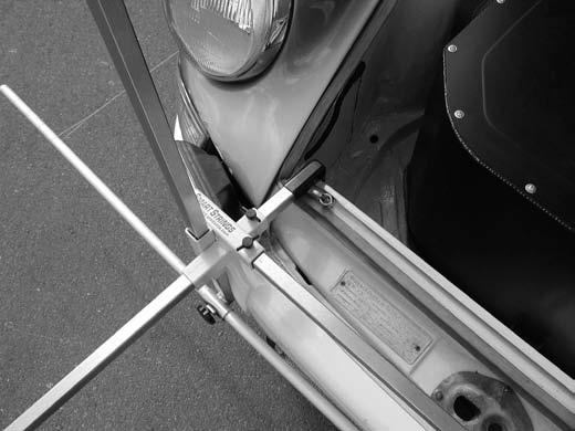
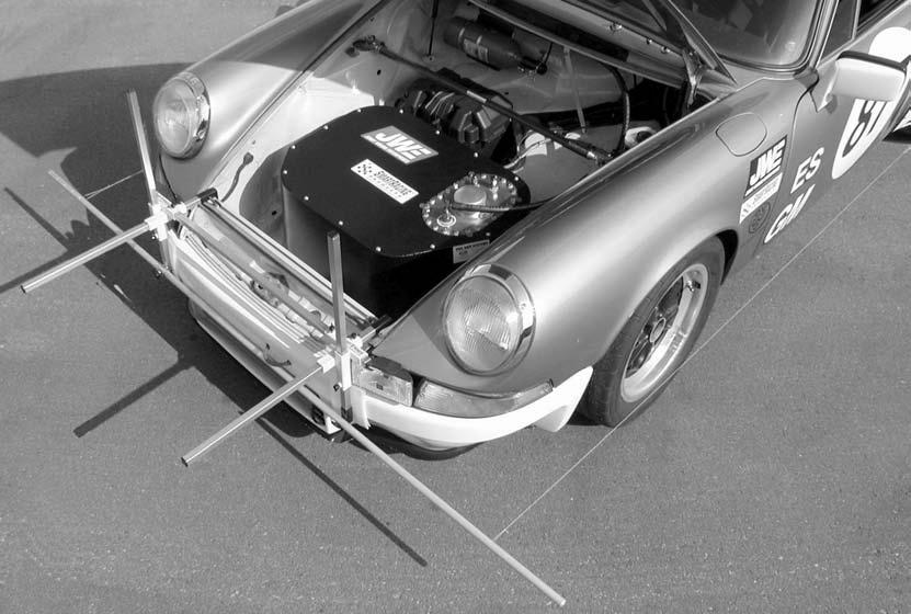
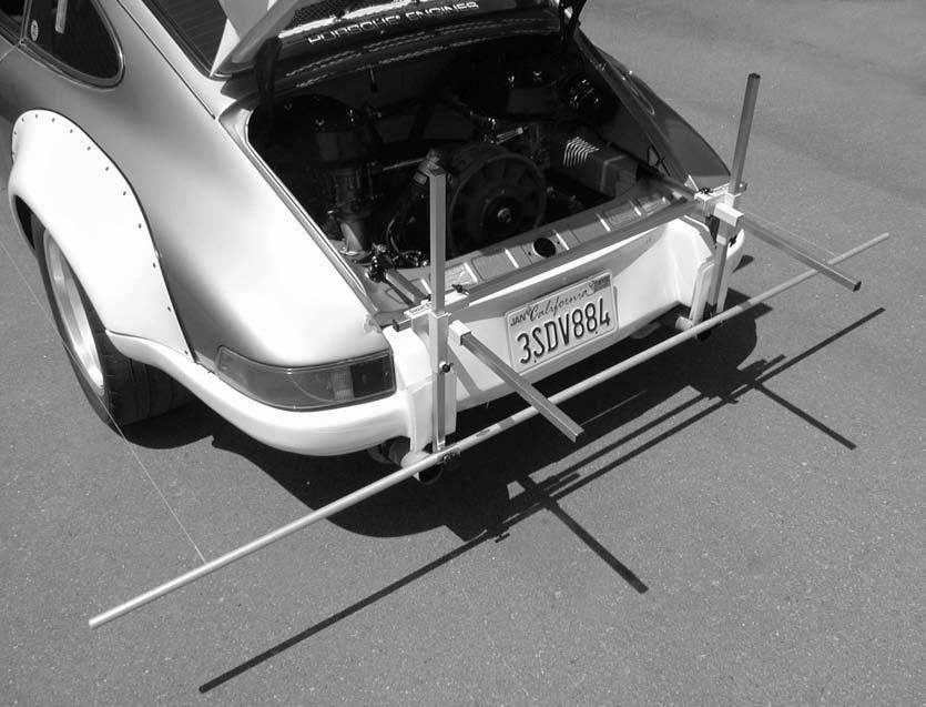
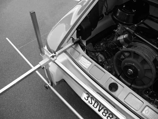
7 Figure 1. Photos of Installation Front & Rear 7

8 8
9 Figure 2. String Layout and Measurements A FRONT A = A C A D -in: The measurement is longer on the leading edge of the wheel than the trailing edge of the wheel. Example: Measurement C is longer than measurement D. -out: The measurement is shorter on the leading edge of the wheel than the trailing edge of the wheel. Example: Measurement C is shorter than measurement D. String B B = B String B Note: This is true for both the front and rear axles. Note: By using the same groove in the bar both front and rear, the strings are now parallel to each other. Measurement A and B will most likely not be the same. 9
10 Figure 3. Settings at Various Tire Diameters Per Wheel /4" 7/32" 3/16" -in = F > R -out = R > F R F Measuring Diameter Forward direction 60' (minutes) = 1 (Deg) String angle angle degrees/wheel /32" 1/8" 3/32".3 1/16".2.1 1/32" Measuring diameter inches 10
11 Figure 4. Mathematical Conversion To convert a known toe setting (call it Ta) and a known tire diameter (call it Da), use this equation to convert to a different tire diameter but using the same toe. For those who hate the math, just use the graph. For those who want the exact number and not interpolate from a graph use this equation: T a D a = T b D b Where Ta = known toe setting Da = known tire diameter If you want the same toe angle with different tire diameters call those Tb and Db. If you do the algebra, you end up with: T b T a X D b = D a You can see that measuring toe accurately is not something that you can take for granted. 11

12 SmartStrings Parts List Item SRP Part No. Part Name Quantity Union Right Side Union Left Side Leg with Holder 36" Leg with Hook 36" Cross Bar 36" Hook 24" String Bar Stud Washer String Line 1 11 Pads 4 12

13 The SmartCamber tool was designed to maximize its measuring potential over a wide variety of wheel/ tire combinations. Utilizing repeatable digital technology, the tool allows accurate measuring regardless of where the vehicle is or what angle surface it is on. There is no misinterpretation with this tool because there are no bubbles or lines to subjectively read. The SmartCamber tool takes all of the guess work out of camber and caster measuring. Since there are nearly an infinite number of wheel and tire combinations, it was necessary to design a tool that would be quick and easy to use. The number one design premise was to allow camber and caster to be measured almost anywhere without removing hub caps, lug nuts or jacking the car off of the ground. Though it is basic in concept, the results are excellent. One fixed and one adjustable standoff allows the owner to use the tool on almost any vehicle. SmartCamber tool with hands free adapter... $ SmartCamber without hands free adapter... $ Hands free adapter... $44.95 Carrying case... $
14 Notes 14
15 Notes 15
16 For Customer Service or Technical Support Call or fax SmartCamber, SmartStrings, SmartRacing Products, SmartTool and SmartLevel are registered trademarks, used by permission where applicable. Copyright Rev. 5 July 2006 Part #011435
17 SmartStrings Parts List Item SRP Part No. Part Name Quantity Union Right Side Union Left Side Leg with Holder 36" Leg with Hook 36" Cross Bar 36" Hook 24" String Bar Stud Washer String Line 1 11 Pads 4 Questions or comments please call or FAX ILL Rev 2
Welcome! mhtml:file://c:\newgti\technical Resources\SmartCamber Manual.mht
 Page 1 of 8 Welcome! Thank you for your purchase of our SmartCamber tool with the SmartTool digital module. You are now the owner of what we believe is the best portable camber and caster measuring tool
ON/OFF Calibrate 0%IN/FT HOLD. Owner s Manual
 Owner s Manual Adjustable long standoff Long standoff Contents Short knurled feet Welcome... 1 Overview... 1 Battery Installation... 1 Optional Hands-Free Adapter... 2 SmartTool - Digital Inclinometer...
Setup Guide and Chassis Tuning Tips (simple version) By Jim Daniels
 By Jim Daniels") This document is released into the public domain and may be reproduced and distributed in its entirety so long as all credit to Jim Daniels remains. If you find this guide helpful please consider donating
This document is released into the public domain and may be reproduced and distributed in its entirety so long as all credit to Jim Daniels remains. If you find this guide helpful please consider donating
ALIGNING A 2007 CADILLAC CTS-V
 ALIGNING A 2007 CADILLAC CTS-V I ll describe a four-wheel alignment of a 2007 Cadillac CTS-V in this document using homemade alignment tools. I described the tools in a previous document. The alignment
Part 3: CHECKING TOE ANGLE -
 CHECKING TOE ANGLE - Part 3: With the caster and camber out of the way and the vehicle on a properly leveled surface, it's time to lay out the string network that will allow you to take accurate measurements
GR40 SLA Installation and Set Up Instructions.
 GR40 SLA Installation and Set Up Instructions. Read these instructions completely before beginning. These instructions are written for experienced installer/technicians with a strong idea as to how a chassis
Adjustable Tie-rod Ends (Mm5TR-1)
") 3430 Sacramento Dr., Unit D San Luis Obispo, CA 93401 Telephone: 805/544-8748 Fax: 805/544-8645 www.maximummotorsports.com 2005-10 Adjustable Tie-rod Ends (Mm5TR-1) 3. Remove the front wheels. 4. Loosen
3430 Sacramento Dr., Unit D San Luis Obispo, CA 93401 Telephone: 805/544-8748 Fax: 805/544-8645 www.maximummotorsports.com 2005-10 Adjustable Tie-rod Ends (Mm5TR-1) 3. Remove the front wheels. 4. Loosen
Customer Engagement - Execution Playbook Module 1 WHEEL ALIGNMENTS ALIGNMENTS
 Customer Engagement - Execution Playbook Module 1 WHEEL ALIGNMENTS -------------------------- ALIGNMENTS 101 ------------------------------ While a wheel alignment is often referred to simply as an alignment,
Basic Wheel Alignment Techniques
 Basic Wheel Alignment Techniques MASTERING THE BASICS: Modern steering and suspension systems are great examples of solid geometry at work. Wheel alignment integrates all the factors of steering and suspension
Roehrig Engineering, Inc.
 Roehrig Engineering, Inc. Home Contact Us Roehrig News New Products Products Software Downloads Technical Info Forums What Is a Shock Dynamometer? by Paul Haney, Sept. 9, 2004 Racers are beginning to realize
Brake, suspension and side slip testers... the facts! October 2009 Technical Newsletter
 October 2009 Technical Newsletter Brake, suspension and side slip testers... the facts! VTEQ brake test lane at Jim Wright Nissan AECS Ltd is the NZ distributor of the VTEQ test equipment since 2001. AECS
2011+ Adjustable Tie-rod Ends (Mm5TR-2)
") 3430 Sacramento Dr., Unit D San Luis Obispo, CA 93401 Telephone: 805/544-8748 Fax: 805/544-8645 www.maximummotorsports.com 2011+ Adjustable Tie-rod Ends (Mm5TR-2) Instructions 1. Set the parking brake
3430 Sacramento Dr., Unit D San Luis Obispo, CA 93401 Telephone: 805/544-8748 Fax: 805/544-8645 www.maximummotorsports.com 2011+ Adjustable Tie-rod Ends (Mm5TR-2) Instructions 1. Set the parking brake
Wheel Alignment Defined
 Wheel Alignment Defined While it's often referred to simply as an "alignment" or "wheel alignment," it's really complex suspension angles that are being measured and a variety of suspension components
2005 to 2008 #08 Metric Nova Chassis Set Up Sheet
 Springs 1 2005 to 2008 #08 Metric Nova Chassis Set Up Sheet Flat end of spring down on tubular lower a-arms. Left Front 800lb. Right Front 750lb. Left Rear 200lb. Right Rear 225lb. On Top of Tube Axle
Disco 3 Clock Spring / Rotary Coupler replacement
 Disco 3 Clock Spring / Rotary Coupler replacement I recently had to change my Clock spring and thought some folks may find it helpful to see what it entailed. I did lots of reading around but couldn t
CHASSIS DYNAMICS TABLE OF CONTENTS A. DRIVER / CREW CHIEF COMMUNICATION I. CREW CHIEF COMMUNICATION RESPONSIBILITIES
 CHASSIS DYNAMICS TABLE OF CONTENTS A. Driver / Crew Chief Communication... 1 B. Breaking Down the Corner... 3 C. Making the Most of the Corner Breakdown Feedback... 4 D. Common Feedback Traps... 4 E. Adjustment
Real Square RSX User Instructions v. 10.2
 Real Square RSX User Instructions v. 10.2 Basic RSX Kit Contents: (1) RSX Shaft Mounted Laser Assembly (2) Axle Alignment Fixtures (Hub Mount or Spindle Thread-on Mount) (2) Wheel Measurement Fixtures
Jeep Wrangler Toe-in and Steering Wheel Center Adjustment
 Jeep Wrangler Toe-in and Steering Wheel Center Adjustment There are really only two adjustments that are adjustable on the front of 1997-2006 Jeep Wranglers. The first is caster, and that is only adjustable
The Mark Ortiz Automotive
 August 2004 WELCOME Mark Ortiz Automotive is a chassis consulting service primarily serving oval track and road racers. This newsletter is a free service intended to benefit racers and enthusiasts by offering
Adjusting brake shoes for AutoPark parking brake
 Adjusting brake shoes for AutoPark parking brake This document is a compilation of several separate writeups. What we're trying to do here is consolidate the necessary information needed for you to make
How to Set the Alignment on Ford Mustangs
 How to Set the Alignment on 1967-1973 Ford Mustangs Let's Get This Straight - Mustang Monthly Magazine Christopher Campbell Technical Editor March 25, 2015 Frontend alignment is one of the most basic adjustments
SHAFT ALIGNMENT FORWARD
 Service Application Manual SAM Chapter 630-76 Section 24 SHAFT ALIGNMENT FORWARD One of the basic problems of any installation is aligning couplings or shafts. Therefore, this section will endeavor to
Real Square 2011 RS400PRO Quick Start User Instructions v. 10.1
 Real Square 2011 RS400PRO Quick Start User Instructions v. 10.1 Technical Help: Please call 540-483-4442, Monday-Friday 8:00AM-5:30PM or e-mail questions to tech@drpperformance.com. RS400PRO Contents:
Fiat - Argentina - Wheel Aligner / Headlamp Aimer #16435
 2017 Fiat - Argentina - Wheel Aligner / Headlamp Aimer #16435 Wheel Aligner / Headlamp Aimer Operation & Maintenance Manual Overview Fori Automation Version 1.2 4/21/2017 TABLE OF CONTENTS Section 1.0
QuickTrick Alignment Tools
 QuickTrick Alignment Tools QuickTrick Alignment Kits are Professional quality tools designed for a lifetime of reliable service. QuickTrick Kits can be used on any vehicle for measurement of the alignment
Tech Tip: Trackside Tire Data
 Using Tire Data On Track Tires are complex and vitally important parts of a race car. The way that they behave depends on a number of parameters, and also on the interaction between these parameters. To
PRESEASON CHASSIS SETUP TIPS
 PRESEASON CHASSIS SETUP TIPS A Setup To-Do List to Get You Started By Bob Bolles, Circle Track Magazine When we recently set up our Project Modified for our first race, we followed a simple list of to-do
HEIDTS SUPERIDE INSTALLATION INSTRUCTIONS OPEN WHEEL SUPERIDE INDEPENDENT FRONT SUSPENSION
 HEIDTS SUPERIDE INSTALLATION INSTRUCTIONS OPEN WHEEL SUPERIDE INDEPENDENT FRONT SUSPENSION Please read these instructions completely before starting your installation. Remember the basic rule for a successful
Hub Stands -- VERSION 5.0
 Hub Stands -- VERSION 5.0 Thanks for choosing our Alignment Hub Stands for your chassis setup needs. We hope you'll find them as handy, accurate, and easy to use as we do! Each stand has a max capacity
Setting The Sag. We ve gathered up a few tutorials on setting the sag. Read them over and decide which one makes the most sense to you.
 Setting The Sag Setting the sag on your bike is the first step in correctly adjusting your suspension. We here at MotorPsycle.com want you to have a safe, great-handling bike. A suspension set up too hard
Installation Procedure GR40 S197 SLA Front Suspension System (Does not include Aluminum Spindle and Hub Instructions)
") Installation Procedure GR40 S197 SLA Front Suspension System (Does not include Aluminum Spindle and Hub Instructions) Please take the time and read these instructions first! The GR40 S197 system is designed
Installation Procedure GR40 S197 SLA Front Suspension System (Does not include Aluminum Spindle and Hub Instructions) Please take the time and read these instructions first! The GR40 S197 system is designed
RZR XP 1000 HD Radius Rod Kit
 RZR XP 1000 HD Radius Rod Kit Polaris RZR XP 1000 2014-2016 Part #: 5201509 Rev. 111517 491 W. Garfield Ave., Coldwater, MI 49036. Phone: 517-278-7768 E-mail: sales-rtpro@sporttruckusainc.com SAFETY WARNING
LG CORVETTE GT2 COIL OVERS
 LG CORVETTE GT2 COIL OVERS THE MOST POWERFUL HEADERS ON THE PLANET Brought to you by LG Motorsports 972-429-1963 Parts Inventory: 1. Assembled Front shock and spring 2. Assembled Rear shock and spring
Dexter Never-Adjust Brake Install
 Dexter Never-Adjust Brake Install Arctic Fox 2007 29-5T Warning: This involves lifting your trailer, working under and around it. If you do not have the correct equipment and knowledge for this, please
ASSOCIATED 1:10 SCALE ELECTRIC BUGGY INSTRUCTION MANUAL FOR THE TEAM ASSOCIATED RC10B Associated Electrics, Inc. RS-1
 ASSOCIATED 1:10 SCALE ELECTRIC BUGGY INSTRUCTION MANUAL FOR THE TEAM ASSOCIATED RC10B4 TT RS-1 2003-2006 Associated Electrics, Inc. FINAL ADJUSTMENTS RADIO ADJUSTMENTS Use the following
QUICKTRICK PRODUCT IN- STRUCTIONS ALIGNMENT SIMPLE SOLUTIONS. Mr & Mrs QuickTrick. Made in the USA
 QUICKTRICK PRODUCT IN- ALIGNMENT SIMPLE SOLUTIONS Thank you for your support of QuickTrick products. You are supporting an American Dream business grown from the Garage and the race track to a World Wide
2. MEASURE VEHICLE HEIGHT. (b) Measure the vehicle height. Measurement points: C: Ground clearance of front wheel center
 Measure the vehicle height. Measurement points: C: Ground clearance of front wheel center") ADJUSTMENT If the wheel alignment has been adjusted, and if suspension or underbody components have been removed/installed or replaced, be sure to perform the following initialization procedure in order
ADJUSTMENT If the wheel alignment has been adjusted, and if suspension or underbody components have been removed/installed or replaced, be sure to perform the following initialization procedure in order
RZR 900 spring/shock installation
 RZR 900 spring/shock installation Thank you for purchasing the Shock Therapy Dual Rate Spring Kit for your RZR 900. Your item list: 2 Front upper coil springs, 2 Front lower coil springs, 2 Rear upper
How to Build with the Mindstorm Kit
 How to Build with the Mindstorm Kit There are many resources available Constructopedias Example Robots YouTube Etc. The best way to learn, is to do Remember rule #1: don't be afraid to fail New Rule: don't
7256 INSTRUCTIONS FOR ELIMINATOR II A-ARM FRONT, 4-LINK REAR, MILD STEEL, INTERMEDIATE, SERIES CHASSIS
 #917256 Page 1 of 7 7256 INSTRUCTIONS FOR ELIMINATOR II A-ARM FRONT, 4-LINK REAR, MILD STEEL, INTERMEDIATE, SERIES CHASSIS ITEM QTY SIZE/PART NO. TUBE CODE DESCRIPTION 1 2 4138 Cage Side 2 2 4208 Forward
Hub Stands -- VERSION 5.0
 Hub Stands -- VERSION 5.0 Thanks for choosing our Alignment Hub Stands for your chassis setup needs. We hope you'll find them as handy, accurate, and easy to use as we do! Each stand has a max capacity
ATASA 5 th. Wheel Alignment. Please Read The Summary. ATASA 5 TH Study Guide Chapter 47 Pages: Wheel Alignment 64 Points
 ATASA 5 TH Study Guide Chapter 47 Pages: 1403 1423 64 Points Please Read The Summary Before We Begin Keeping in mind the Career Cluster of Transportation, Distribution & Logistics Ask yourself: What careers
RHINO SUSPENSION SYSTEM INSTALLATION INSTRUCTIONS
 PARTS INCLUDED: 2 FRONT UPPER A-ARMS 2 FRONT LOWER A-ARMS 2 UNI-BALL JOINTS 2 UNI-BALL JOINT STUDS 2 UNI-BALL JOINT CAPS 2 RETAINING RINGS 1 FRONT SHOCK ASSEM. 2 DELRON STEERING STOPS 2 SHOCK MOUNT SPACERS
Caring for Your Manual Wheelchair
 Caring for Your Manual Wheelchair Your wheelchair is a machine that will help you to be more active and mobile. Check the wheelchair often to be sure that it is working well and safely. There may be a
LUGGAGE RACK MG TD with Original Steel Wheels. Installation Instructions. Step 1
 Created on 7/7/2003 8:34:00 PM by Michael Grant Last Revised 2/2/2008 1:55:00 PM Page 1 of 14 1 2 3 243-705 LUGGAGE RACK MG TD with Original Steel Wheels If your TD has been converted to wire wheels, please
INSTRUCTIONS FOR STRUT FRONT, 4-LINK REAR, ROADSTER CHASSIS
 #917406 Page 1 of 5 7406 INSTRUCTIONS FOR STRUT FRONT, 4-LINK REAR, ROADSTER CHASSIS ITEM QTY SIZE/PART NO. TUBE CODE DESCRIPTION 1 1 4215 Front frame rail strut 1 5/8 (pair) 2 1 4236 Roadster firewall
HONDA AN & AZ 600 STEERING RACK
 HONDA AN & AZ 600 STEERING RACK Bill Colford 1 8/30/2010 Introduction This will be a review of how to remove, clean, inspect and reassemble the Honda 600 steering rack. Upon completion of this presentation
Yamaha Viking Rackzilla Install/Removal
 2014-15 Yamaha Viking Rackzilla Install/Removal Kit Numbers: 8001850, 8001790 Full refund will NOT be granted to any kits that are damaged, scratched, or altered in any fashion. Kit Contents: Part Number
Measuring Threaded Holes
 Measuring Threaded Holes It s a common question In PC-DMIS I can use the pitch function within a circle feature so the probe would "follow" the thread. How are tapped holes measured in Calypso? I have
The Mark Ortiz Automotive
 July 2004 WELCOME Mark Ortiz Automotive is a chassis consulting service primarily serving oval track and road racers. This newsletter is a free service intended to benefit racers and enthusiasts by offering
NEW CAR TIPS. Teaching Guidelines
 NEW CAR TIPS Teaching Guidelines Subject: Algebra Topics: Patterns and Functions Grades: 7-12 Concepts: Independent and dependent variables Slope Direct variation (optional) Knowledge and Skills: Can relate
STEP #1: Remove the wheels from the truck. There are (6) 21mm lug nuts holding each wheel on... Remember Lefty Loosy, Righty Tighty.
 21mm lug nuts holding each wheel on... Remember Lefty Loosy, Righty Tighty.") - CustomTacos.com Page 1 of 36 How-To: Toytec Lift Install Read all of these install instructions prior to installing Toytec's suspension lift. I cannot be held responsible for any damages or personal
- CustomTacos.com Page 1 of 36 How-To: Toytec Lift Install Read all of these install instructions prior to installing Toytec's suspension lift. I cannot be held responsible for any damages or personal
1940 Hudson SERVICING THE FRONT SUSPENSION SYSTEM
 1940 Hudson SERVICING THE FRONT SUSPENSION SYSTEM Source of this material is from 1940 Series, Issue 3, November-December Hudson Service Magazine SERVICING THE FRONT SUSPENSION SYSTEM No set rule can be
Installation Instructions
 Instructions Created by an: Revised 7-11-17 LRT 2005-2017 3/1 Leveling/ Lift Kit for Toyota Tacoma by Low Range Off-Road (SKU# LR-LRTACO) Installation Instructions Suggested Tools: CAUTION: Safety glasses
AMT Motorsport C7 Corvette Camber Kit User s Guide. 8 Upper Control Arm Studs and hardware for rear upper control arm adjustments
 AMT Motorsport C7 Corvette Camber Kit User s Guide Thank you for purchasing the AMT Motorsport Camber Kit for the C7 Corvette. We believe this is the most versatile camber kit available on the market,
A /F/X Body Instruction Packet Rear Disc Conversion
 A /F/X Body Instruction Packet Rear Disc Conversion 64-72 A Body / 67-81 F Body / 62-74 X Body This kit is for axles with a 3 1/8 spread center to center on the top two bolt holes (pictured left). Rotor
Fig 1 An illustration of a spring damper unit with a bell crank.
 The Damper Workbook Over the last couple of months a number of readers and colleagues have been talking to me and asking questions about damping. In particular what has been cropping up has been the mechanics
BIG BAR SOFT SPRING SET UP SECRETS
 BIG BAR SOFT SPRING SET UP SECRETS Should you be jumping into the latest soft set up craze for late model asphalt cars? Maybe you will find more speed or maybe you won t, but either way understanding the
Wench With a Wrench. By Gail Wagner. A Shocking Discussion. Should I or Shouldn t I? That is The Question
 By Gail Wagner Wench With a Wrench A Shocking Discussion There are lots of things you want out of your Miata driving experience and one of them is a smooth ride. A key factor that contributes to this experience
Teacher s Guide: Safest Generation Ad Activity
 Teacher s Guide: Safest Generation Ad Activity Introduction Today s 11- and 12-year-old preteens are very smart about vehicle safety. They have grown up using car seats and booster seats more consistently
Computerscales DX Model Operating Instructions
 16892 146 th St SE, Monroe, WA 98272 (360) 453-2030 Computerscales DX Model 72641 Operating Instructions QUICK START INSTRUCTIONS: 1) Set up pads alongside kart (they are interchangeable). 2) Connect cables
APPENDIX A: Background Information to help you design your car:
 APPENDIX A: Background Information to help you design your car: Solar Cars: A solar car is an automobile that is powered by the sun. Recently, solar power has seen a large interest in the news as a way
Ford 8, 9 Small Bearing Installation Instructions Rear Disc Conversion
 Ford 8, 9 Small Bearing Installation Instructions Rear Disc Conversion This kit is for Ford 9 rear axles with the small (2.835 ) style bearing and Ford 8 rear ends. This kit is designed to work with axles
SHOCK DYNAMOMETER: WHERE THE GRAPHS COME FROM
 SHOCK DYNAMOMETER: WHERE THE GRAPHS COME FROM Dampers are the hot race car component of the 90s. The two racing topics that were hot in the 80s, suspension geometry and data acquisition, have been absorbed
Thanks for Ordering The Kawasaki KLX Adjustable Lowering Kit From
 www.scootworks.com Thanks for Ordering The Kawasaki KLX Adjustable Lowering Kit From READ THIS BEFORE UNPACKING YOUR KIT! This instruction booklet contains detailed steps for installing the rear suspension
INSTALLATION GUIDE. TCP TIER-14 Bump Steer Conversion Kit - Early Mustang to Late Spindle
 READ ALL INSTRUCTIONS COMPLETELY AND THOROUGHLY UNDERSTAND THEM BEFORE DOING ANYTHING. CALL TOTAL CONTROL PRODUCTS TECH SUPPORT (916) 388-0288 IF YOU NEED ASSISTANCE. INSTALLATION GUIDE TCP TIER-14 Bump
Installation Instructions
 Instructions Created by an: DIY Alignment Toe Set Tool, 5 Patterns (SKU# DIY-TST) Installation Instructions CAUTION: Safety glasses should be worn at all times when working with vehicles and related tools
Computerscales DX Model Operating Instructions (Also applies to models 72632, 72635, 72636)
") 16892 146 th St SE, Monroe, WA 98272 (360) 453-2030 Computerscales DX Model 72634 Operating Instructions (Also applies to models 72632, 72635, 72636) QUICK START INSTRUCTIONS: 1) Set up pads alongside
16892 146 th St SE, Monroe, WA 98272 (360) 453-2030 Computerscales DX Model 72634 Operating Instructions (Also applies to models 72632, 72635, 72636) QUICK START INSTRUCTIONS: 1) Set up pads alongside
STEERING SYSTEM Introduction
 STEERING SYSTEM Introduction The steering makes it possible to change direction. The steering must be reliable and safe; there must not be too much play in the steering. It must be possible to steer accurately.
Installation Instructions
 79-04 Ford Mustang Perfect Fit K-Member Part # 20022 Installation Instructions Congratulations on your purchase of the AFCO Perfect Fit K-member for the 79-04 Ford Mustang. Please read and understand each
Next, chase the threads in the lower A-arm mounts with the 5/8-18 tap and blowout any remaining particles.
 Next, chase the threads in the lower A-arm mounts with the 5/8-18 tap and blowout any remaining particles. Now, apply some anti-seize to the threads of the pivot stud. Also put anti-seize inside the bore
How To: Fix That Ugly Hanging E-Brake Cable A CFans Members Mod Project by dirtydawg
 How To: Fix That Ugly Hanging E-Brake Cable A CFans Members Mod Project by dirtydawg Skill Level: Easy Disclaimer: Please use caution and seek professional assistance when necessary. ColoradoFans.com,
INSTRUCTIONS FOR STRUT FRONT, 4-LINK REAR, 1 5/8 FRAME, FULL SIZE, 4130 ELIMINATOR CHASSIS
 #917230 Page 1 of 6 7230 INSTRUCTIONS FOR STRUT FRONT, 4-LINK REAR, 1 5/8 FRAME, FULL SIZE, 4130 ELIMINATOR CHASSIS ITEM QTY SIZE/PART NO. TUBE CODE DESCRIPTION 1 2 4350 Cage Side 2 2 4351 Forward strut
CALDERA 10E Spur Gear Change
 CALDERA 10E Spur Gear Change www.thirdcoastrc.com ebay handle - little*oak Click Below to Visit our Ebay Store EBAY STORE (Please take a moment and bookmark my website, ebay store, and save me as an ebay
Perfect Park 7000 Installation & Unloading Instructions Operating Manual
 Perfect Park 7000 Installation & Unloading Instructions Operating Manual 1) Always file a claim with the truck line if the lift has been damaged! (If you don t originally notice the damage, but find some
55-64 Full Size GM (Impala, Bel Air, etc.) This kit is for axles with a 3 3/8 spread center to center on the top two bolt holes (pictured left).
 This kit is for axles with a 3 3/8 spread center to center on the top two bolt holes (pictured left).") SUM-BK1624A Full Size GM Installation Instructions Rear Disc Conversion 55-64 Full Size GM (Impala, Bel Air, etc.) This kit is for axles with a 3 3/8 spread center to center on the top two bolt holes (pictured
SUM-BK1624A Full Size GM Installation Instructions Rear Disc Conversion 55-64 Full Size GM (Impala, Bel Air, etc.) This kit is for axles with a 3 3/8 spread center to center on the top two bolt holes (pictured
*NOTE* The following suspension system will not work with heavy duty axle housings as pictured below.
 1964 ½ - 1970 Ford Mustang Triangulated 4-Link Suspension Installation Instructions Tech Line: 1-855-693-1259 www.totalcostinvolved.com Read and understand these instructions before starting any work!
IRS-151 INSTALLATION INSTRUCTIONS `55-57 CHEVY INDEPENDENT REAR SUSPENSION
 IRS-151 INSTALLATION INSTRUCTIONS `55-57 CHEVY INDEPENDENT REAR SUSPENSION Please read these instructions completely before starting your installation. Remember the basic rule for a successful installation:
1964 1/2-70 Mustang Torque Arm Rear Suspension Installation Instructions
 1964 1/2-70 Mustang Torque Arm Rear Suspension Installation Instructions 1-800-984-6259 www.totalcostinvolved.com Version 2 (c) 2008 Total Cost Involved Engineering, Inc. All Rights Reserved. Page 1 of
TRAILING ARM CHEVY PICK-UP
 TRAILING ARM 1947 1954 CHEVY PICK-UP Congrats on choosing the best riding and handling rear suspension for your Chevy. Trailing arm suspension can be tricky to install correctly, so please follow our recommendations,
Assembly Manual. 1/10th Formula 1 Car
 Assembly Manual 1/10th Formula 1 Car Center Pivot Bag 1 3374 - Center Pivot Socket 40194 - Hard Anodized Alum Pivot ball 3254-2-56 *Note - Sometimes it is helpful to slightly over-tighten the top clamp
BBK Ceramic Long Tube Headers (99-04 Cobra and Mach 1) - Installation Instructions
 - Installation Instructions") BBK Ceramic Long Tube Headers (99-04 Cobra and 03-04 Mach 1) - Installation Instructions The below installation instructions work for the following products: BBK Ceramic Long Tube Headers (99-04 Cobra
BBK Ceramic Long Tube Headers (99-04 Cobra and 03-04 Mach 1) - Installation Instructions The below installation instructions work for the following products: BBK Ceramic Long Tube Headers (99-04 Cobra
7260 INSTRUCTIONS FOR ELIMINATOR II STRUT FRONT, 4-LINK REAR, MILD STEEL, FULL SIZE, SERIES CHASSIS
 #917260 Page 1 of 6 7260 INSTRUCTIONS FOR ELIMINATOR II STRUT FRONT, 4-LINK REAR, MILD STEEL, FULL SIZE, SERIES CHASSIS ITEM QTY SIZE/PART NO. TUBE CODE DESCRIPTION 1 2 4139 Cage Side 2 2 4250 Forward
TECHNOLOGY AND SIMPLICITY.
 TM DISCOVER THE PERFECT COMBINATION OF SERIES TECHNOLOGY AND SIMPLICITY. INTRODUCING THE V-SERIES WHEEL ALIGNMENT SYSTEMS For more information regarding the V-SERIES call 800.362.4618 (US) or 800.362.4608
Front Wheel Alignment Kit for Can-Am Spyder.
 Front Wheel Alignment Kit for Can-Am Spyder. The Alignment Kit consists of : 2 yellow Shinty LE007 magnetic-base Laser Levels ( batteries included ) NB: These levels are accurate but made of plastic. They
How to use the Multirotor Motor Performance Data Charts
 How to use the Multirotor Motor Performance Data Charts Here at Innov8tive Designs, we spend a lot of time testing all of the motors that we sell, and collect a large amount of data with a variety of propellers.
LOS ANGELES UNIFIED SCHOOL DISTRICT
 LOS ANGELES UNIFIED SCHOOL DISTRICT THE SCHOOL REPAIR AND CONSTRUCTION PROGRAM The Safety Sheet January 27, 2004 This edition of the Safety Sheet addresses Crane Safety Awareness, and is intended to provide
Peg-Harness installation instructions
 Peg-Harness installation instructions I know it s not the easiest thing to do, but PLEASE READ THESE INSTRUCTIONS COMPLETELY so you will understand what you are trying to accomplish before you start drilling
THE TORQUE GENERATOR OF WILLIAM F. SKINNER
 THE TORQUE GENERATOR OF WILLIAM F. SKINNER IN 1939, WHICH WAS THE START OF WORLD WAR TWO, WILLIAM SKINNER OF MIAMI IN FLORIDA DEMONSTRATED HIS FIFTH-GENERATION SYSTEM WHICH WAS POWERED BY SPINNING WEIGHTS.
Bag 1. Bag 1. Center Pivot. Center Pivot
 8 00734 01901 5 Center Pivot Bag 1 3374 - Center Pivot Socket 4019 - Alum Pivot ball 3254-2-56 Button Head *Note - Sometimes it is helpful to slightly over-tighten the top clamp screws, then work the ball
Chevrolet 3100 IFS Kit
 1947-54 Chevrolet 3100 IFS Kit Congratulations on your purchase on what we believe is the finest IFS kit available for 1947-54 Chevrolet pickups with stock frames. We have invested many hours into designing
INSTALLATION GUIDE Bolt-On Drag-Race Strut Clip Chevy II
 INSTALLATION GUIDE 7702 Bolt-On Drag-Race Strut Clip 1962-67 Chevy II Description: STRUT CLIP 4130 BOLT ON 62-67 CHEVY II, INCLUDES 4130 ROUND TUBE FRAME CLIP, DOUBLE-ADJUSTABLE STRUTS, ADJUSTABLE-HEIGHT
Pro/Series 2000 Tubular A-Arm Front Suspension
 11 Mennonite Church Road Spring City, PA 19475 (610) 948-7303 Installation Instructions Pro/Series 2000 Tubular A-Arm Front Suspension (Pinto-Style) CAUTION!!! The most important requirement for a successful
RS-2 SINGLE ACTION REAR BUMPER WITH TIRE CARRIER INSTALL MANUAL FOR JEEP WRANGLER ALL MODELS.
 RS-2 SINGLE ACTION REAR BUMPER WITH TIRE CARRIER INSTALL MANUAL FOR 2007-2016 JEEP WRANGLER ALL MODELS. Rear Bumper Installation Instructions 1) Remove factory rear bumper, (this includes all tow hitch
All of the control valves that we install the Mk. 16IQ positioner on are factory calibrated for proper operation prior to shipment.
 1 Troubleshooting The first thing you need is information... Try to find out what is wrong and why. Getting a serial number (found on the valve tag (see above)) and application parameters are always helpful
Speakers and Motors. Three feet of magnet wire to make a coil (you can reuse any of the coils you made in the last lesson if you wish)
") Speakers and Motors We ve come a long way with this magnetism thing and hopefully you re feeling pretty good about how magnetism works and what it does. This lesson, we re going to use what we ve learned
Speakers and Motors We ve come a long way with this magnetism thing and hopefully you re feeling pretty good about how magnetism works and what it does. This lesson, we re going to use what we ve learned
USE THE PARTS LIST BELOW TO MAKE SURE YOUR KIT IS COMPLETE BEFORE INSTALLATION. IF ANY PIECES ARE MISSING, PLEASE CONTACT:
 55-59 Chevy Truck Chassis Custom IFS & 4-Link Install Instructions Tech line: 1-855-693-1259 www.totalcostinvolved.com Read and understand these instructions before starting any work! USE THE PARTS LIST
Wheel A L I G N M E N T
 Wheel ALIGNMENT excellence in Wheel alignment REDUCE TIME AND INCREASE ACCURACY From our versatile geoliner 580 Prism to our top-of-the-range geoliner 790, our wheel alignment systems feature the best
UNIBODY/FRAME/WHEEL ALIGNMENT II ABCT 2212
 UNIBODY/FRAME/WHEEL ALIGNMENT II ABCT 2212 A. Course Description Credits: 6.00 Lecture Hours/Week: 1.00 Lab Hours/Week: 5.00 OJT Hours/Week: 0 Prerequisites: None Corequisites: None MnTC Goals: None This
Installing the Wireless Charging upgrade kit in a 2018 XT5 (Platinum version)
") Installing the Wireless Charging upgrade kit in a 2018 XT5 (Platinum version) September 2, 2018 Tools needed: Wireless charger upgrade kit Plastic trim tools 7 mm nut driver Background: I purchased the
Installing the Wireless Charging upgrade kit in a 2018 XT5 (Platinum version) September 2, 2018 Tools needed: Wireless charger upgrade kit Plastic trim tools 7 mm nut driver Background: I purchased the