Operating Temperature. 32 to 122 F (0 to 50 C)
|
|
|
- Meredith Reed
- 6 years ago
- Views:
Transcription
1
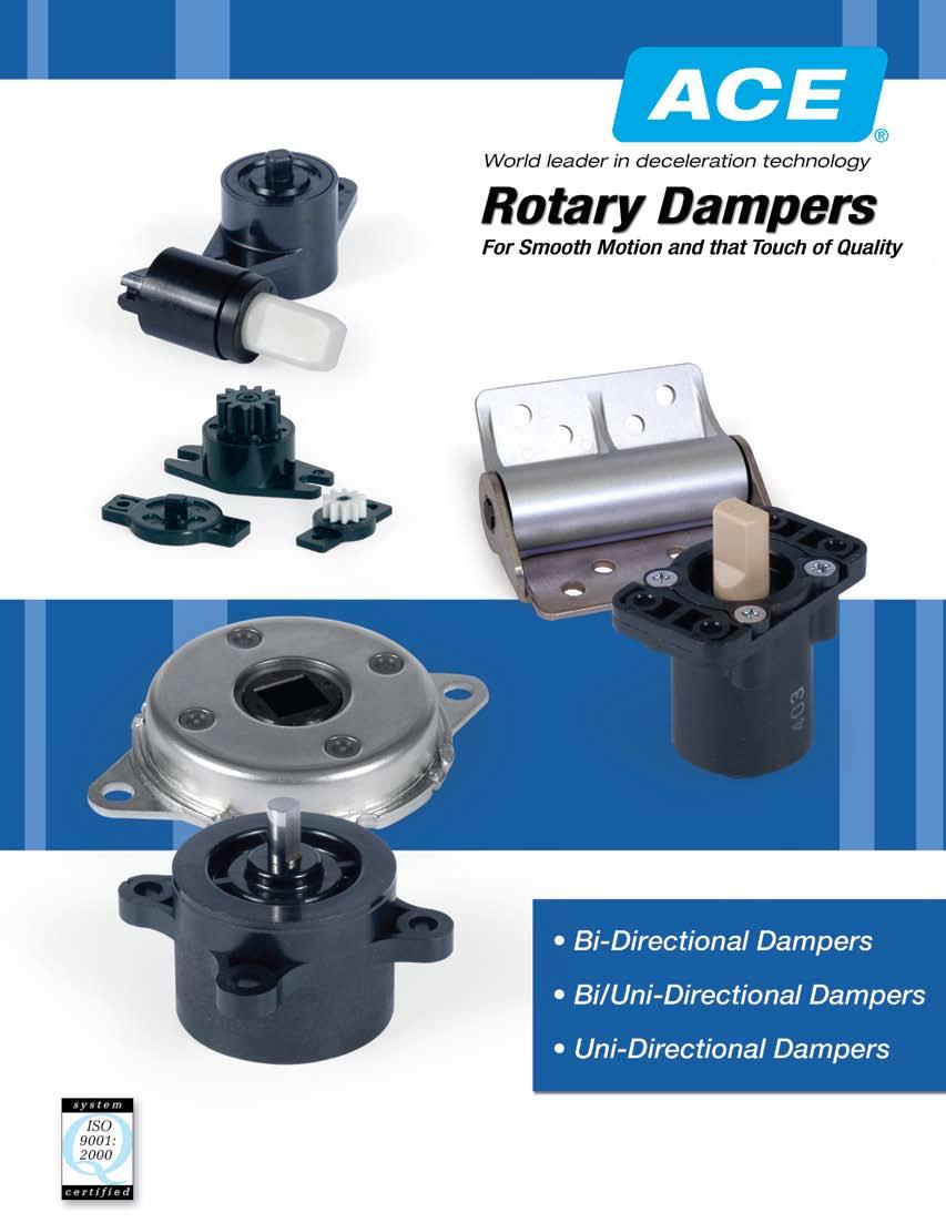
2 Rotary Dampers GENERAL INFORMATION ACE Controls Inc. offers a world class range of compact rotary dampers that enable products to function with a smooth mechanical motion, resulting in that touch of quality. Incorporation of ACE s reliable dampers can protect delicate electronics and extend the life of your product by helping to prevent lid and access panel closure damage. In addition, superior noise suppression is obtained as a direct result of the smooth flowing motion provided by ACE s dependable rotary dampers. In today s liability conscious world it pays to incorporate elements into your product design that reduce your chances of liability litigation. ACE s rotary dampers can help make your product safer for today s discerning, safety conscious consumer. Rotary motion control models are available with damping in both directions of rotation. Alternatively, certain model sizes are available with the option of uni-directional damping, i.e. damping action only in a clockwise or counterclockwise rotation and free travel in the opposite rotation. This is achieved by means of an internal one way clutch on the output shaft. If your application calls for locking in both directions of motion, the versatile ACE Controls bi-directional locking series of rotary dampers can be added to enhance the functionality of your new product design. General Models may vary. See individual specifications or consult factory. Maximum Cycle Rates Nominal Torque Rating Operating Temperature Storage Temperature Cycles per minute Measured at 0 rpm & 73 F 3 to 1 F (0 to 0 C) -4 to 140 F (-0 to 0 C) Conversions Physical Quantity Divide By To Obtain Torque gf cm 7 in oz Torque gf cm 11 in lb Torque kgf cm 1.1 in lb Length mm.4 in Length cm.4 in Angular Velocity deg/s rpm Angular Velocity deg/s 7.30 rad/s Angular Velocity rpm 9. rad/s Temperature TF = 3 + (9/) TC TC = (/9) (TF - 3) Where: TF = Temperature Fahrenheit TC = Temperature Celsius Mountings To Avoid Rotary dampers are designed for controlling rotary and linear motion. Shown below are examples of mountings that should be avoided.
3 GENERAL INFORMATION Applications 3 Indicates rotary damper locations
4 Structure & Principles GENERAL INFORMATION Rotary Damper-Basic Structure Cap Silicone oil Rotor Main body Basic Principles Rotary dampers utilize the principle of fluid resistance to dampen movement. Oil viscosity is utilizied to provide the braking force of the damper. The torque is determined by the viscosity of the oil; the gap between the rotor and the body and the surface area of the parts. Temperature Characteristics 4 Temperature Characteristics The torque of the rotary damper varies according to the temperature. The higher the temperature, the lower the torque. The lower the temperature, the higher the torque. torque Speed Characteristics The torque of the rotary damper varies according to cycle rate. In general, if the cyle rate goes up, the torque increases. If the cycle rate goes down, the torque decreases. Speed Characteristics ambient temperature Vane Damper-Basic Structure torque rotation speed Main Body Basic Principles Silicone oil Vane Oil viscosity is utilizied to provide the braking force of the damper. The torque is determined by the viscosity of the oil, the gap between the moving parts and the surface area of the parts. When the shaft rotates, the oil in the damper moves into the opposite chamber. The torque is determined by the oil pressure on the vane.
5 GENERAL INFORMATION Selection Procedure Selection Procedure C, D, E, F, & G Series 1). Determine the torque about the pivot point for your application. Also, determine a desired angular velocity for the pivoting object. (See example below.) ). From the catalog pages in the section, choose a rotary damper that provides the closest torque to what was calculated in step 1. 3). On the catalog page of the model selected, look at the torque vs rpm graph to determine the rotation speed using the selected damper. 4). If the speed is too fast for your requirement, select the next higher torque damper. If the speed is too slow, select the next lower torque damper. ). Develop a part number from the table on the catalog page of the damper selected. ). If a satisfactory model cannot be found, contact ACE applications engineering at to discuss a custom model for your application. Torque Calculation Example L = Length from pivot to the end of the lid θ = Angle between the lid and horizontal W = Free weight of the lid To calculate the torque about the pivot point for the lid pictured above use the following formula: T = (L/) x (W) x (Cos θ) Where: T = Torque L/ = 1/ the length of the lid from the pivot to the end (center of gravity) W = Free weight of the lid (actual weight of lid) θ = Angle between the lid and horizontal Note: as the lid closes, θ decreases and the torque increases.


 0. 0.4 40 30 0 00 0 0.")
6 E Series Bi-Directional Damper..1 Applications include: computer disk drives, CD players and instrumentation equipment. Gear Type Tooth profile Module 0. Pressure angle Number of teeth Pitch circle diameter.0 in oz (gf cm) Specification - mm Standard spur gear Involute (full) 0 degrees Relationship Between Torque and Temperature 0 rpm 14 +/ / ºC ºF Relationship Between Torque and rpm s 73 º F (3 º C) in oz (gf cm) (.) rpm RT E 0 G1 Control Type Series Directions Torque Code Gear RT = Two Way E Blank = Two Way in oz / (gf cm) G1 = With Gear 0 = 0.14 () 00 = 0.8 (0) 300 = 0.4 (30) 400 = 0. (40) Blank = Without Gear
 Specification - mm Standard spur gear Involute (full) 0 degrees Relationship Between Torque and Temperature 0 rpm.")
7 Bi-Directional Damper G Series..1 Applications include: audio cassette door on a tape deck and automobile ashtrays. Gear Type Tooth profile Module 0. Pressure angle Number of teeth 14 Pitch circle diameter 7.0 in oz (gf cm) Specification - mm Standard spur gear Involute (full) 0 degrees Relationship Between Torque and Temperature 0 rpm / / º C º F in oz (gf cm) Relationship Between Torque and rpm s 73 º F (3 º C) (.4) rpm RT G 00 G1 Control Type Series Directions Torque Code Gear RT = Two Way G Blank = Two Way in oz / (gf cm) G1 = With Gear 00 = 0.8 (0) 300 = 0.4 (30) 40 = 0.3 (4) 00 = 0.83 (0) 1 = 1.39 (0) Blank = Without Gear
 POM Silicone Standard torque is decided at 0 rpm and 3 C ± C Within limits different torques can be obtained by using a different viscosity oil. 4.")
8 L1 Series Bi-Directional Damper Max. rotation speed: Max. cycle rate: Operating temperature: Weight: Body and cap material: Rotating shaft material: Oil type: 0 rpm cycles/min 0 to 0 C 14.1 g PC (polycarbonate) POM Silicone Standard torque is decided at 0 rpm and 3 C ± C Within limits different torques can be obtained by using a different viscosity oil. 4. Temperature Characteristics Rotary damper torque varies according to the ambient temperature. Refer to the diagram below which shows the torque change under different temperatures. This occurs because the oil viscosity varies according to the temperature ±0.3 torque Nm 40 Temperature characteristics at 0 rpm º C ± Speed Characteristics Rotary damper torque varies according to the rotation speed. Refer to the diagram below. The starting torque is different than the standard torque. torque Nm 40 Speed characteristics at 3 º C rpm RT L1 0 Control Type Series Directions RT = Two Way L1 Blank = Two Way Torque Code in oz / (gf cm) 0 = 7.77 (000 ± 400) 30 = 41. (3000 ± 00)
 NYLON (with glass) Silicone Standard")
9 Bi-Directional Damper DT-47A & 7A Series Max. rotation speed: Max. cycle rate: Operating temperature: Weight: Body and cap material: Rotating shaft material: Oil type: 0 rpm 1 cycles/min - to 0 C 47A: 49g, 7A: 7g Steel (SCP440) NYLON (with glass) Silicone Standard torque is decided at 0 rpm and 3 C ± C R4. ø4. DT-47A ± Temperature Characteristics Rotary damper torque varies according to the ambient temperature. Refer to the chart to the right which shows the torque change under different temperatures. This occurs becuase the oil viscosity varies according to the temperature. torque Nm 8 4 Temperature characteristics at 0 rpm DT-7 DT º C 9 R. DT-7A ± Speed Characteristics Rotary damper torque varies according to the rotation speed. Refer to the diagram to the right. torque Nm 8 4 Speed characteristics at 3 º C DT DT-47 ø. This damper is a two way torque damper. There is no support for the shaft in the damper structure. Support for the shaft must be provided. Please use the recommended shaft dimensions. When mounting the shaft, ensure as tight a fit as possible. Refer to the dimensions in the diagrams at the right. DT 47A rpm 8 0 ø DT-47A 0 ø DT-7A Control Type Series Directions DT = Two Way 47A 7A Blank = Two Way DT-47A-03 DT-7A-03 Torque Code Nm (kgf cm) 03 = ± 0.3 (0 ± 3) 03 = 4.7 ± 0. (47 ± )
 Nylon (with glass) Silicone Standard")
10 DT-3A/B & 70A/B Series Bi-Directional Damper Max. rotation speed: Max. cycle rate: Operating temperature: Weight: Body and cap material: Rotating shaft material: Oil type: 0 rpm 1 cycles/min - to 0 C 3A: 9, 70A: 11g Steel (SCP440) Nylon (with glass) Silicone Standard torque is decided at 0 rpm and 3 C ± C R. - ø R0. DT-3A Temperature Characteristics Rotary damper torque varies according to the ambient temperature. Refer to the chart at the right which shows the torque change under different temperatures. This occurs because the oil viscosity varies according to the temperature. Temperature characteristics at 0 rpm torque Nm 8 DT-70 DT º C - R. - ø DT-70A ± ± Speed Characteristics Rotary damper torque varies according to the rotation speed. Refer to the chart at the right. torque Nm 8 4 Speed characteristics at 3 º C DT-70 DT R rpm This damper is a two way torque damper. There is no support for the shaft in the damper structure. Support for the shaft must be provided. Please use the recommended shaft dimensions. When mounting the shaft, ensure as tight a fit as possible. Refer to the dimensions in the drawings to the right. ø ø DT 3B Ø DT 70B DT 3A/B 703 Control Type Series Directions DT = Two Way 3A/B 70A/B Blank = Two Way DT- 3A/B-703 DT- 70A/B-903 Torque Code Nm (kgf cm) 703 =.7 ± 0.7 (7 ± 7.0) 903 = 8.7 ± 0.8 (87 ± 8.0)

11 Bi-Directional Locking Damper A1 and B1 Locking Series Applications include: briefcases, display lids, furniture doors, or any small panel that would benefit from being locked against rotation. Operation of A1/B1 Bi-Directional Locking Series In Figure 1 free movement is available in the counterclockwise direction and the unit is locked against movement in the clockwise direction. In Figure a load exceeding the rated torque of the locking mechanism is applied in the clockwise direction and the lock function is cancelled. In Figure 3 free movement is now available in the clockwise direction but is locked against movement in the counterclockwise direction. In Figure 4 a load exceeding the rated torque of the locking mechanism is applied in the counterclockwise direction and the lock function is cancelled. The damper has returned to its original state in Figure Selection Procedure A1/B1 Series 1. Determine the torque about the pivot point for your application.. In the section, select a model which has a higher torque rating than what was calculated in step 1, above. 3. The difference between the torque determined in step 1 and the torque rating of the model selected in step is the external load that must be applied to cancel the locking function. If this difference is too small, select a model with a higher torque rating. If this difference is too large, select a model with a lower torque rating. 4. Develop a part number from the table on the specification page.. If a satisfactory model cannot be found contact ACE applications engineering at to discuss a custom model for your application. RL A1 03 RL B1 0 Control Type RL = Bi-Directional Locking Series A1 Torque Code in oz / (gf cm) 0 = 1.74 (.0) Control Type RL = Bi-Directional Locking Series B1 Torque Code in oz / (gf cm) 0 = 4.34 (.0)

12 HD-B1/B Series-Friction Rotary Damper Bi-Directional Damper (Fixed) Max. rotation speed: Max. cycle rate: Operating temperature: HD-B1/B-133: HD-B1/B-133-1: Body case material: Shaft collar material: Shaft material: 1 rpm cycles/min 0-0 C 0 g 40 g Aluminum die-casting Urethane rubber Steel (SCP440) The torque is determined at rpm and C ± C Body case (Aluminum die-casting ADC) Rotary shaft (Steel SUM) Bushing (Urethane rubber) 1 R HD-B1-133 HD-B-133 R. ø ø HD-B HD-B ø.. 14 R.. Damper Usage One half only can be used as a damper 1. This damper can be used in two directions.. Damper can be used even without shaft support. 3. Lubricants must not be used in or near the damper. 4. If damper is used in or near water or oil, the torque will be lost.. Damper cannot be used for more than one continuous 30º rotation.. Damper can be used as a free stop hinge. HD B1 133 Model Series Torque Code HD B1 Nm (kgfcm) B 133 = 1.3 ± 0.34 (13. ± 3.4)
13 Bi-Directional Damper (Fixed) HD-B1/B Series-Friction Rotary Damper Please use the following formula to determine the torque. M: Material L: Length θ: Degrees a: Max temperature rate N: Damper number (Torque) = M x 9.8 x 0. x L x cos θ 0. x α x N (Nm) Max temperature rate a Room temperature ( ± º C) 1 Max 40º C 0.7 Max 0º C 0.0 G L M pivot point 13 Temperature Characteristics Rotary damper torque varies according to ambient temperature. This occurs because the oil viscosity varies according to the temperature. Please refer to the chart below. Speed Characteristics Rotary damper torque varies according to the rotation speed. Refer to the chart below. temperature at 3ºC action angle at 90º rotation speed Nm 1 Nm ºC 0 1 rpm
14 C Series Bi/Uni-Directional Damper Applications include: VCR loading mechanisms, glove box doors and instrumentation equipment. Gear Type Tooth profile Module 0.8 Pressure angle Number of teeth 11 Pitch circle diameter 8.8 Specification - mm Standard spur gear Involute (full) 0 degrees in oz (gf cm) Relationship Between Torque and Temperature 0 rpm 1 3.+/ ºC ºF Relationship Between Torque and rpm s 73 º F (3 º C) 7..4 in oz (gf cm) rpm RN C R 01 G1 Control Type Series Directions Torque Code Gear RN = One Way C in oz / (gf cm) RT = Two Way R = Clockwise L = Counterclockwise Blank = Two Way 01 =.78 (00) 301 = 4.17 (300) G1 = With Gear Blank = Without Gear

15 Bi/Uni-Directional Damper D Series Applications include: window shades, sliding closet doors, printer covers and paper trays for copy machines. Gear Type Tooth profile Module 1.0 Pressure angle Number of teeth 1 Pitch circle diameter 1.0 Specification - mm Modified spur gear Involute (full) 0 degrees in oz (gf cm) Relationship Between Torque and Temperature 0 rpm / R ºC ºF Relationship Between Torque and rpm s 73 º F (3 º C) in oz (gf cm) rpm RN D R 01 G1 Control Type Series Directions Torque Code Gear RN = One Way D in oz / (gf cm) RT = Two Way R = Clockwise L = Counterclockwise Blank = Two Way 01 =.94 (00) = (00) 1 = 0.83 (100) G1 = With Gear Blank = Without Gear
 0 rpm cycles/min 0 to 0 C RT-F 11.")
16 F Series Bi/Uni-Directional Damper Applications include: copy machine lids, dining room table folding extensions and more. Max. rotation speed: Max. cycle rate: Operating temperature: Weight: Body and cap material: Rotating shaft material: Oil Type: Relationship Between Torque and Temperature 0 rpm in lb (kgf cm) 0 rpm cycles/min 0 to 0 C RT-F 11. g RN-F 93. g Polycarbonate + glass SUS (stainless steel) Silicone R ºC ºF Relationship Between Torque and rpm s 73 º F (3 º C) 40 +/ in lb (kgf cm) rpm RN F R 03 Control Type Series Directions RN = One Way RT = Two Way F R = Clockwise L = Counterclockwise Blank = Two Way Torque Code in lb/(kgf cm) 03 = 17.3 (0)
 Oil Type: Silicone Standard torque is decided at 0 rpm and 3 C ± C Within limits different torques can be")
17 Bi/Uni-Directional Damper K Series 47 3 Max. Rotation Speed: 0 rpm Max. Cycle Rate: cycles/min Operating Temperature: 0 to 0 C Weight: RT-K 78.3g RN-K.g Body and cap material: Polycarbonate + glass Rotating shaft material: SUS (stainless steel) Oil Type: Silicone Standard torque is decided at 0 rpm and 3 C ± C Within limits different torques can be obtained by using a different viscosity oil. Temperature Characteristics Rotary damper torque varies according to the ambient temperature. Refer to the diagram below which shows the torque change under different temperatures. This occurs because the oil viscosity varies according to the temperature.. R torque Nm 3 1 Temperature characteristics at 0 rpm º C 40 +/ Speed Characteristics Rotary damper torque varies according to the rotation speed. Refer to the diagram below. The starting torque is different than the standard torque torque Nm 0.3 Speed characteristics at 3 º C rpm RN K R 3 Control Type Series Directions RN = One Way RT = Two Way K R = Clockwise RN-K-R3 RN-K-R0 L = Counterclockwise RN-K-L3 RN-K-L0 Blank = Two Way RT-K-3 RT-K-0 Torque Code Nm, kgf cm, Ncm R3 = 0.98 ± 0. Nm L3 = ± kgfcm 3 = ± kgfcm 0 = 0 ± Ncm
18 FYT & FYN-H1() Series Bi/Uni-Directional Damper (Adjustable) º.º M Max. rotation angle: º Operating temperature: - to 0 C Weight: H1:40 ±, H:3 ± g Body and cap material: ZDC (zinc die-cast) Rotating shaft material: SC (carbon steel) Oil type: Silicone Torque is determined at 3º C ± ºC 1. The FYN-H1 action is designed for use in applications as shown in diagram A. The torque is highest when the cover is horizontal and lowest when the cover is vertical. If used in applications as shown in diagram B, the damper will not provide a statisfactory closing action. ± A damper with a higher torque can be made to special order. 18 A The torque is stronger, cover can slowly close B The torque is stronger, cover cannot close well Adjusting Screw ø8 0.1 M=kg L=0.4m. Please use the following formula to determine the torque. Example: M = kg L = 0.4 m T = x 0.4 x 9.8/ = 9.8 Nm FYN-H1 *4 can be used. ø Dimensional tolerances for shaft 3. When the damper is mounted using the shaft, ensure as tight a fit as possible. FYN H1 R 4 Control Type Series Directions FYN = One Way FYT = Two Way H1 H R = Clockwise FYN-H1() L = Counterclockwise FYN-H1() Blank = Two Way FYT=H1() Torque Code Nm (kgf cm) 4 = (00) Reverse Torque *4 = 0. () *FYN models only

19 Bi/Uni-Directional Damper (Adjustable) FYT & FYN-H1() Series Temperature Characteristics Rotary damper torque varies according to the ambient temperature. Refer to the chart below which shows the torque change under different temperatures. This occurs because the oil viscosity varies according to the temperature. rotation end-point torque applied in this direction º.º.º rotation starting point Damper action angle is ±.º from center. Exceeding the maximum action angle will result in damage to the damper. A stopper should be used. Please refer to the drawings to the right. FYN-H1 () temperature characteristics rotor action angle 30 FYN-H1-L FYN-H-L torque applied in this direction sec 0 º rotation starting point.º.º rotation end-point ºC ambient temperature rotor Torque Adjustment Method 1. FYT-H1(H) and FYN-H1(H) torque is adjustable by turning the adjustment screw.. To increase torque turn screw in clockwise direction(h). 3. To reduce torque turn screw in counterclockwise direction(l). 4. Do not rotate the adjustment screw more than 30º as the damper may be damaged.. After adjusting please fix the adjusment screw, otherwise the torque may change during operation. 30 (max) adjustment angle 180 FYN-H1-R FYN-H-R Torque Adjustable Range Torque and Adjustment Screw Relationship adjustment screw torque increase (clockwise) torque decrease (counterclockwise) loaded torque 1. measurement of hexagonal spanner Damper torque direction differs according to the model, please choose an appropriate direction for your application. lock screw
20 FYT & FYN-D1() Series Bi/Uni-Directional Damper (Fixed) Max. Rotation Angle: º Operating Temperature: - to 0 C Weight: D1:1 ±, D: ± g Body and cap material: ZDC (zinc die-cast) Rotating shaft material: SC (carbon steel) Oil Type: Silicone Torque is determined at 3º C ± ºC º.º M ± The FYN-D1 action is designed for use in applications as shown in diagram A. The torque is highest when the cover is horizontal and lowest when the cover is vertical. If used in applications as shown in diagram B, the damper will not provide a statisfactory closing action. A damper with a higher torque can be made to special order. 0 A The torque is stronger, cover can slowly close B The torque is stronger, cover can not close well Adjusting Screw ø8 0.1 ø M=kg L=0.4m Dimensional tolerances for shaft. Please use the following formula to determine the torque. Example: M = kg L = 0.4 m T = x 0.4 x 9.8/ = 9.8 Nm FYN-D1 *4 can be used. 3. When the damper is mounted using the shaft, ensure as tight a fit as possible. FYN D1 R 4 Control Type Series Directions FYN = One Way FYT = Two Way D1 D R = Clockwise FYN-D1() L = Counterclockwise FYN-D1() Blank = Two Way FYT=D1() Torque Code Nm (kgf cm) 4 = (00) Reverse Torque *4 = 0. () *FYN models only
21 Bi/Uni-Directional Damper (Fixed) FYT & FYN-D1() Series Temperature Characteristics Rotary damper torque varies according to the ambient temperature. Refer to the chart below which shows the torque change under different temperatures. This occurs because the oil viscosity varies according to the temperature. rotation end-point torque applied in this direction º.º.º rotation starting point Max damper action angle is º Do not exceed º or damage will result. Please use mechanical stop. Please refer to the drawings to the right. rotor action time FYT/N-D1 (D) temperature characteristics FYN-D1-L FYN-D-L torque applied in this direction (sec) 4.º º.º 1 rotation starting point rotation end-point rotor (ºC) ambient temperature FYN-D1-R FYN-D-R FYN-D1 torque is nonadjustable, however dampers with torque ranging from to 0 Nm can be supplied by using a different viscosity oil. Damper torque direction differs according to the model, please choose an appropriate direction for your application.
 Rotating shaft material: SC (carbon steel) Oil type: Silicone Torque is determined at 3º C ± ºC 8 9")

22 FYT/N-LA3 Series Bi/Uni-Directional Damper (Adjustable) Max. rotation angle: º Operating temperature: - to 0 C Weight: 1.7 kg Body and cap material: ZDC (zinc die-cast) Rotating shaft material: SC (carbon steel) Oil type: Silicone Torque is determined at 3º C ± ºC 8 9 ± rotor location mark 80 Adjusting Screw 3 0 P ø. + adjustment screw damper action angle is ± º from center mark Temperature Characteristics Rotary damper torque varies according to the ambient temperature. Refer to the chart below which shows the torque change under different temperatures. This occurs because the oil viscosity varies according to the temperature. (%) damping rate / temperature characteristics M=0kg L=0.4m. Use the following formula to determine the torque. Example: M = 0 kg L = 0.4 m T = 0 x 0.4 x 9.8/ = 39. Nm FYN-LA3 can be used damping number vary rate 0 + Damping number adjustment screw: + torque increases - torque decreases (ºC) ambient temperature torque adjustment screw FYN LA3 R Control Type Series Directions FYN = One Way FYT = Two Way LA3 R = Clockwise FYN-LA3R L = Counterclockwise FYN-LA3L Blank = Two Way FYT=LA3 Torque Code Nm (kgf cm) 40 (400) Damping Rate -0 Nm/rad/sec

23 Bi/Uni-Directional Damper (Adjustable) FYT/N-LA3 Series Important Damper Information Rotation 1. When the damper is mounted using the shaft, ensure as tight a fit as possible.. Damper action angle is ± º from center. 3. Damper torque direction differs according to the model Max damper action angle is ± º. Do not exceed ± º or damage will result. Use mechanical stop. 1,-0,0 70 9, Rotary Damper Damping Number Count Method 1. Steady movement in a straight line = FL²t d. Steady rotation = T w F = lever force (N) L = distance between center of damper axes to lever effect-point (m) d = lever removing distance (m) t = lever removing time T = torque is on shaft (Nm) w = angle speed (rad/sec) 3 3. Deceleration of mass moving in a straight line = MVL² d M = quality (kg) V = speed (m/s) L = distance between center of damper axes to lever effect-point (m) d = lever removing distance (m) 4. Critical damping of vibrating mass = MfL² 0.08 M = quality (kg) f = vibrancy frequency (Hz) L = distance between center of damper axes to lever effect-point (m) Controls linear movement F d 3 Controls rotational motion L T Impact absorption M V d M Vibration absorption
 Silicone 3 9 1 1 4 Temperature")
24 FYN-M1 Series Uni-Directional Damper Max. rotation angle: Max. cycle rate: Operating temperature: Weight: Body and cap material: Rotating shaft material: Oil type: 180 cycles/min 0 to 0 C 17 ± g PBT ZDC (zinc die-cast) Silicone Temperature Characteristics Rotary damper torque varies according to the ambient temperature. Refer to the chart below which shows the torque change under different temperatures. This occurs because the oil viscosity varies according to the temperature. FYN-M1 Series Temperature Characteristics action angle sec º complementary angle complementary angle º middle double rotor face action angle 180º ambient temperature 0 ºC 180º (R4) (R4) º complementary angle FYN-M1-L º complementary angle FYN-M1-R Standard torque is decided at 0 rpm and 3 C ± C Within limits different torques can be obtained by using a different viscosity oil. FYN M1 R 1 Control Type Series Directions Torque Code FYN = One Way M1 R = Clockwise L = Counterclockwise Nm (kgf cm) 1 = 0.1 (1.) = 0. (.) 3 = 0.3 (3.) 0 = 0.0 (.0)


25 8 Uni-Directional Damper FYN-K1 Series Max. rotation angle: Operating temperature: Weight: Body and cap material: Rotating shaft material: Oil type: 8 - to 0 C 33 ± 3 g PBT PPS Silicone R R Use the following formula to determine the torque. Example: M = kg L=0.4m L = 0.4 m M=kg T = x 0.4 x 9.8/ = 3.9 Nm Select damper: FYN-K1-403 Torque is determined at 3 C ± C FYN-K1 torque is nonadjustable. However, dampers with torque ranging from to 4 Nm can be supplied by using a different viscosity oil. Temperature Characteristics Rotary damper torque varies according to the ambient temperature. Refer to the chart below which shows the torque change under different temperatures. This occurs because the oil viscosity varies according to the temperature. FYN-K1 Temperature Characteristics 13 action time T (sec) Clockwise damping 4 End Position Counterclockwise damping ºC ambient temperature FYN K1 R 403 Control Type Series Directions Torque Code FYN = One Way K1 R = Clockwise Nm (kgf cm) L = Counterclockwise 403 = 4 (40)


 FYN-N1 Temperature Characteristics CCW 1. 8-0.")
26 FYN-N1 Series Uni-Directional Damper Max. rotation angle: Operating temperature: Weight: Body and cap material: Rotating shaft material: Oil type: 1 - to 0 C 1 ± 1 g PBT PPS Silicone White end cap: counterclockwise damping Black end cap: clockwise damping As shown in the diagram below, the maximum action angle is 1º. Do not exceed 1º or damage will result. Standard torque is decided at 0 rpm and 3 C ± C Within limits different torques can be obtained by using a different viscosity oil. Use the following formula to determine the torque. Example: M = 1. kg L=0.4m L = 0.4 m T = 1. x 0.4 x 9.8/ M=1.kg =.9 Nm Select damper: FYN-N1-303 Temperature Characteristics Rotary damper torque varies according to the ambient temperature. Refer to the chart below which shows the torque change under different temperatures. This occurs because the oil viscosity varies according to the temperature Rotation 1 The rotating starting point is pre-set at the factory. Torque applied in this direction 1º 90º Rotation Starting Point action time T (sec) FYN-N1 Temperature Characteristics CCW rotation end-point FYN-N1-L rotor ambient temperature 0 ºC FYN N1 R 3 Control Type Series Directions Torque Code FYN = One Way N1 R = Clockwise L = Counterclockwise Nm (kgf cm) 3 = 1 () 03 = (0) 303 = 3 (30)


27 Uni-Directional Damper FYN-P1 Series Max. rotation angle: Operating temperature: Weight: Body and cap material: Rotating shaft material: Oil type: 11 - to 0 C. ± 1 g PBT PBT Silicone Torque is determined at 3 C ± C Use the following formula to determine the torque Rotation 0 1 Example: M = 1 kg L = 0.3 m T = 1 x 0.3 x 9.8/ = 1.47 Nm Select damper: FYN-P1-13 M=1kg L=0.3m Temperature Characteristics Rotary damper torque varies according to the ambient temperature. Refer to the chart below which shows the torque change under different temperatures. This occurs because the oil viscosity varies according to the temperature. 7 FYN-P1 Temperature Characteristics action time T (sec) ambient temperature 0 ºC FYN P1 R 3 Control Type Series Directions Torque Code FYN = One Way P1 R = Clockwise L = Counterclockwise Nm (kgf cm) 3 = 1 () 13 = 1. (1) 183 = 1.8 (18)
28 DN-47A & 3A Series Uni-Directional Damper Max. rotation speed: Max. cycle rate: Operating temperature: Weight max: Body and cap material: Rotating shaft material: Oil type: 0 rpm 1 cycles/min - to 0 C 10 g Steel (SCP440) Nylon (with glass) Silicone.3 ±.03 Standard torque is decided at 0 rpm and 3 C ± C Within limits different torques can be obtained by using a different viscosity oil. 8 -R. -R4. -R4. -ø. ø DN-47A-R/L ± Temperature Characteristics Rotary damper torque varies according to the ambient temperature. This occurs because the oil viscosity varies according to the temperature. Speed Characteristics Rotary damper torque varies according to the rotation speed. This is a one way damper which features a special axle insert which can be easily reversed by the user to provide damping in the opposite direction. There is no support for the shaft in the damper structure. Support for the shaft must be provided. ø DN-3A-R/L903 DN 47A R Control Type Series Directions DN = One Way 47A 3A R = Clockwise DN-47A-R03 DN-3A-R903 L = Counterclockwise DN-47A-L03 DN-3A-L03 Torque Code Nm (kgf cm) ± 0.3 (0 ± 3) 8. ± 0.8 (8 ± 8)
29 Uni-Directional Damper DN-7A & 70A Series Max. rotation speed: Max. cycle rate: Operating temperature: Weight: Body and cap material: Rotating shaft material: Oil type: 0 rpm 1 cycles/min - to 0 C 7A: 94g, 70A:10g Steel (SCP440) Nylon (with glass) Silicone R. ø. 14 ± Standard torque is decided at 0 rpm and 3 C ± C Within limits different torques can be obtained by using a different viscosity oil. Temperature Characteristics Rotary damper torque varies according to the ambient temperature. This occurs because the oil viscosity varies according to the temperature Speed Characteristics Rotary damper torque varies according to the rotation speed. This is a one way damper which features a special axle insert which can be easily reversed by the user to provide damping in the opposite direction. 9 R. ø. DN-7A-R/L There is no support for the shaft in the damper structure. Support for the shaft must be provided DN-70A-R/L114 DN 7A R 3 Control Type Series Directions DN = One Way 7A 70A R = Clockwise DN-7A-R3 DN-70A-R114 L = Counterclockwise DN-7A-L3 DN-70A-L114 Torque Code Nm (kgf cm) 3 =. ± 0. ( ± ) 114 = 11 ± 1.1 (1 ± 11)
 POM Silicone 0. ± 0.")
30 FYN-S1 Series Uni-Directional Damper Max. rotation angle: Operating temperature: Weight: Body and cap material: Rotating shaft material: Oil type: to 0 C 0 ± g ZDC (zinc die-cast) POM Silicone 0. ± 0. Torque is determined at 3 C ± C FYN-S1 Series dampers are self-compensating and can maintain the same action time as the load changes. 1. ø. 30º R. 70 ± ± 1 Temperature Characteristics Rotary damper torque varies according to the ambient temperature. Refer to the chart below which shows the torque change under different temperatures. This occurs because the oil viscosity varies according to the temperature action time T (sec) FYN-S1 Temperature Characteristics 1 3. The maximum action angle of the damper is 130 as shown below. Do not exceed 130. A mechanical stop is recommended. 4 torque applied in this direction (L) º torque applied in this direction (R) ambient temperature 0 ºC 130º 130º max. rotation angle max. rotation angle FYN-S1-L º FYN-S1-R FYN S1 R 4 Control Type Series Directions Torque Code FYN = One Way S1 R = Clockwise Nm (kgf cm) L = Counterclockwise 4 = (0)
31 Uni-Directional Damper FYN-D3 Series ø4. ± Max. rotation speed: 8º Operating temperature: - to 0 C Weight: 1 ± 1 g Body and cap material: ZDC (zinc die-cast) Shaft material: SC (carbon steel) Oil type: Silicone Torque is determined at 3 C ± C MX0.8 8 ø º ø8 ø ø1 0 ø M R1. 31 The FYN-H1 action is designed for use in applications as shown in diagram A. The torque is highest when the cover is horizontal and lowest when the cover is vertical. If used in applications as shown in diagram B, the damper will not provide a satisfactory closing action. A damper with a higher torque can be made to special order. A The torque is stronger, cover can slowly close B The torque is stronger, cover cannot close well M=kg ø L=0.4m Dimensional tolerances for shaft Use the following formula to determine the torque. Example: M = kg L = 0.4 m T = x 0.4 x 9.8/ = 9.8 Nm FYN-D3-4 can be used. When the damper is mounted using the shaft, ensure as tight a fit as possible. FYN D3 R 4 Control Type Series Directions FYN = One Way D3 R = Clockwise FYN-D3-R4 FYN-D3-R03 FYN-D3-R703 L = Counterclockwise FYN-D3-L4 FYN-D3-L03 FYN-D3-L703 Torque Code Nm (kgf cm) 4 = (0) 03 = (0) 703 = 7 (70) Reverse Torque 4 = (0) 03 = 1 () 703 = 1 ()
32 FYN-D3 Series Uni-Directional Damper Temperature Characteristics Rotary damper torque varies according to the ambient temperature. Refer to the chart to the right which shows the torque change under different temperatures. This occurs because the oil viscosity varies according to the temperature. action time 1 FYN-D3 temperature characteristics (sec) Max damper action angle is 180º Do not exceed 180º or damage will result Please use mechanical stop Please refer to the following diagram (ºC) ambient temperature rotation starting point rotation starting point torque applied in this direction rotor rotor torque applied in this direction 180º 180º rotation end point rotation end point FYN-D3-L FYN-D3-R. FYN-D3 torque is non-adjustable, however dampers with torque ranging from to Nm can be supplied by using a different viscosity oil. 7. Damper torque direction differs according to the model, please choose an appropiate direction for your application.
33 Uni-Directional Damper (Fixed) HD-A1 Series Max. rotation speed: 10º Operating temperature: - to 0 C Weight: 4 g Body material: ZDC (zinc die-cast) + painting Hinge material: SUS304 (stainless steel) Max. Action time: 4 ±. sec. (Torque: loaded torque 9.8 Nm, Fall angle 0º to 0º) HD-A1-1-*** 10º ø HD-A1--*** 10º Temperature Characteristics Rotary damper torque varies according to the ambient temperature. This occurs because the oil viscosity varies according to the temperature. This damper is available in mounting styles: HD-A1-1-XXX (Fixing outside) HD-A1--XXX (Fixing inside) 10º largest opening angle 10º torque direction largest opening angle 90º torque direction cover damper cover stopper damper stopper HD-A1 1 4 Model HD-A1 Mounting Styles 1 Torque Code Nm (kgf cm) 4 = (0) 03 = (0) Reverse Torque 4 = under 1 () 03 = under 0. ()
34 RX-A1 Series Uni-Directional Damper Material: Nylon Operating temperature: 0 C to 0 C Weight: 0.01 kg Max rotation angle: 10º Do not use damper as final end stop. Fit external mechanical stops Ø 1 Ø 34 3 Ø º rotation Shaft GFK (GRP) RX A1 R 03 Control Type Series Directions Torque Code RX = One Way A1 R = Clockwise L = Counterclockwise Nm (kgf cm) 03 = ± 0. (0 ± )
 7 ± º (action angle of hinge) ± º (action angle of damper) 0 to 0 C 1 ± 0. kg Applications include: photocopy and test machine covers 4 ø4.3 1 1 94 1 1 ±0.")
35 Spring Hinged Damper (Fixed) DSH-B1 Series Spring torque: Action angle: Operating temp: Weight: 8.8º ± 1.7cNm (θ = 0º damper closed spring torque).39 ± 1.08cNm (θ = 7º damper open spring torque) 7 ± º (action angle of hinge) ± º (action angle of damper) 0 to 0 C 1 ± 0. kg Applications include: photocopy and test machine covers 4 ø ±0.3 7º 7º θ ±0. 7. θ1 θ ± ø. DSH B ± DSH-B1 action illustration. This is a combined spring/ damper hinge. (The damper is hidden inside the spring) θ 3 : Spring engaged-automatically returns to 90º position. θ : Spring engaged-free stop action-stops in desired position from 7º to º θ 1 : Damper engaged-automatic controlled closing from º to 0 Model Series Torque Code Nm (kgf cm) 134 = 13 (130) max ACE Controls is focused daily on continuous improvement. We therefore reserve the right to change models, dimensions or specifications without notice or obligation.


36 Additional ACE Controls Products Industrial & Safety Shock Absorbers Velocity Controllers ACE ACE Gas Springs & Hydraulic Dampers TUBUS Bumpers Locked Series ACE Controls Inc Industrial Park Drive Farmington Hills, MI 4833 Toll Free: Phone: Fax:
Air-Oil Systems, Inc.
 Rotary Dampers GENERAL INFORMATION ACE Controls Inc. offers a world class range of compact rotary dampers that enable products to function with a smooth mechanical motion, resulting in that touch of quality.
Mechanical Rotary Dampers
 Introduction Mechanical Our are sealed maintenance free units. They are available with fixed or adjustable damping rates. The damping can be clockwise, anticlockwise or in both directions. The outer body
Overview of Profi le Dampers TR/TR-L
 TUBUS-Series Overview of Profi le Dampers Physical Properties of TUBUS Profile Dampers Energy Capacity per unit weight Operating Lifetime PUR Rubber Gummi TUBUS Energy Capacity per unit volume ACE TUBUS
Small dampers refine end product
 4 Motion Control Small dampers refine end product ACE rotary dampers mainly provide an invisible yet valuable service as a maintenance-free machine element to allow controlled deceleration of rotary or
ANTI-VIBRATION Rotary Dampers - Continuous Rotation Bi-Directional : Ncm
 FRTE Bi-Directional :.1 -. 2.1 2.5 2. 1 ±.5 2 ±.5 Ø Ø7.2 Ø2.5 ±.5 Ø2.1 (5.5 without gear) torque.7..5...2.1 FRTE2 (at 2 C) 2 Model 2 5 Rpm torque.5...2.1 FRTE2 (at 2 Rpm) 2 5 C Model 2 torque varies with
LOCKED SERIES. Machine Failures. General Information. set up. maintenance. reconditioning. repair 30.4%
 General Information LOCKED SERIES 2 Lowering machinery process costs is key in today s world. According to a recent study approximately a third of all machine stoppages result in unexpected damage and
252 DISK DAMPER Picture Item Name Size Thickness Damping direction Torque Page UDD-L 80 x 51.6mm 19.6mm N.cm 254 UDD-R 80 x 51.6mm 19.6mm
 S 2 1 S 252 DISK DAMPER Picture Item Name Size Thickness Damping direction Torque Page UDD-L 80 x 51.6mm 19.6mm 50-300N.cm 254 UDD-R 80 x 51.6mm 19.6mm 50-300N.cm 254 Picture Item Name Diameter Length
Ultra-High Energy Absorption SC 25 to SC 650 Heavyweight Shock Absorbers. Featuring New SC 25, 75 & 190 Models Features...
 Ultra-High Energy Absorption SC 5 to SC 650 Heavyweight Shock Absorbers Featuring New SC 5, 75 & 190 Models Features. Piston Tube Design for Long Cycle Life Stainless Steel Piston Rod Integral Mechanical
Innovation in. Mechanical Motion & Vibration Controls
 Innovation in Mechanical Motion & Vibration Controls ACE Controls Inc. located in Farmington Hills, Michigan, is a leading innovator in deceleration, vibration and motion control technology. For over a
Series CRB2. Rotary Actuator Vane Style. Size: 10, 15, 20, 30, 40 CRB2 CRBU2 CRB1 MSU CRJ CRA1 CRQ2 MSQ MRQ D- 20- Series Variations.
 Rotary Actuator Vane Style Series :,,,, 4 1 Series Variations Standard Vane type Port location Rotating angle Shaft type Fluid (S) ouble vane () Side ported (Nil) Axial ported (E) 9 18 27 ouble shaft W
Theory of Machines. CH-1: Fundamentals and type of Mechanisms
 CH-1: Fundamentals and type of Mechanisms 1. Define kinematic link and kinematic chain. 2. Enlist the types of constrained motion. Draw a label sketch of any one. 3. Define (1) Mechanism (2) Inversion
P1X Series. Compact Rodless Air Cylinders Contents
 Compact DL RC P1Z P1X OSP-P Contents Features and Benefits... 130 Ordering Information... 131 Specifications, Weights and Forces... 132 Technical Data... 133-136 Sensor Adapter Bracket... 137 Basic Dimensions...
High Speed, High Pressure Vane Motors
 ENGINEERING DATA High Speed, High Pressure Vane Motors M - Motors 25M, 35M, 45M, 5M w w w. F l u i D y n e F P. c o m E m a i l : c s @ F l u i D y n e F P. c o m Dependable Versatile The M Motor is a
Pneumatic Rotary Actuators. PRO-PRN Series PRO-PRN. PDE2613TCUK Pneumatic Rotary Actuators & Airmotors
 Pneumatic Rotary Actuators Series 173 Rotary actuators are an efficient and easy way to generate torque from compressed air, in a very compact size. They are ideal for the compact applications in a wide
Vickers 45. VMQ Series 30 Vane Pumps. Fixed Displacement, For Industrial and Mobile Applications (4.188)
") [ (4.188) 49,4 (1.94) /21,8 /.86) 174,7/172,3 (6.88/6.78) 332,9/33,5 (13.11/13.1) "M" is marked if metric port threads No marking if inch port threads AS-568-152 O-ring Vickers 45 65,3 (2.57) 13 (5.1 VMQ
[ (4.188) 49,4 (1.94) /21,8 /.86) 174,7/172,3 (6.88/6.78) 332,9/33,5 (13.11/13.1) "M" is marked if metric port threads No marking if inch port threads AS-568-152 O-ring Vickers 45 65,3 (2.57) 13 (5.1 VMQ
Linear Thrusters/PneuMoment
 /PneuMoment Extruded TE Series 3.3-3.10 3.11-3.16 T Series Multiple Position T4 Series Movable Housing 3.17-3.22 3.23-3.24 3.25-3.28 3.29-3.32 Pneu-Moment Checklist PneuMoment Pneumatic Actuators PneuMoment
Linear Drive with Ball Screw Drive Series OSP-E..SB
 Linear Drive with Ball Screw Drive Series OSP-E..SB Contents Description Data Sheet No. Page Overview 1.30.001E 47-50 Technical Data 1.30.002E-1 to 5 51-55 Dimensions 1.30.002E-6, -7 56-57 Order instructions
ISO Cylinders Compact Cylinders TC08 Series Plastic Finger Tight Fittings
 ISO 632 Cylinders ISO 15552 Cylinders Compact Cylinders TC08 Series Pilot Valves 207-208 209-212 213-21 215 TC15 Series Pilot Valves TC08 Series Solenoid Valves CD7 Series Solenoid Valves CD12 Series Solenoid
BMVSS Knee a low-cost passive prosthesis to replicate able-bodied motion
 BMVSS Knee a low-cost passive prosthesis to replicate able-bodied motion Molly Berringer, Paige Boehmcke, Jason Fischman, Athena Huang, Danny Joh, Cali Warner Mentor: Murthy Arelekatti May, 2, 2017 Final
Simple Gears and Transmission
 Simple Gears and Transmission Contents How can transmissions be designed so that they provide the force, speed and direction required and how efficient will the design be? Initial Problem Statement 2 Narrative
Linear Drive with Toothed Belt Series OSP-E..B. Contents Description Overview Technical Data Dimensions Order Instructions 46
 Linear Drive with Toothed Belt Contents Description Page Overview 35-38 Technical Data 39-43 Dimensions 44-45 Order Instructions 46 35 The System Concept ELECTRIC LINEAR DRIVE FOR POINT-TO-POINT APPLICATIONS
Code No: R Set No. 1
 Code No: R05310304 Set No. 1 III B.Tech I Semester Regular Examinations, November 2007 KINEMATICS OF MACHINERY ( Common to Mechanical Engineering, Mechatronics, Production Engineering and Automobile Engineering)
FTP Series HIGH FORCE ELECTRIC PRESS ACTUATOR
 FTP Series HIGH FORCE ELECTRIC PRESS ACTUATOR Ideal hydraulic press replacement Industry-leading power density Rugged and reliable Flexible and precise 952.500.6200 www.exlar.com 75 FTP Series High Force
Linear Actuator with Ball Screw Series OSP-E..S. Contents Description Overview Technical Data Dimensions 89
 Linear Actuator with Ball Screw Series OSP-E..S Contents Description Page Overview 79-82 Technical Data 83-88 Dimensions 89 79 The System Concept ELECTRIC LINEAR ACTUATOR FOR HIGH ACCURACY APPLICATIONS
Adjustable Series Hydraulic Shock Absorbers OEM Series. Adjustable Series OEM XT. Overview. Features and Benefits
 XT Hydraulic Shock Absorbers Series Overview Xtreme Mid-Bore Series Large Series Small Bore Platinum Series Enidine Adjustable Hydraulic Series shock absorbers offer the most flexible solutions to energy
Vickers. Vane Pumps. V Series - Low Noise Vane Pumps High Performance Intravane Pumps For Industrial Applications.
 Vickers Vane Pumps V Series - Low Noise Vane Pumps High Performance Intravane Pumps For Industrial Applications Revised 6/95 560 Introduction Vickers offers the most complete line of hydraulic intravane
Linear Actuator with Toothed Belt Series OSP-E..B
 Linear Actuator with Toothed Belt Series OSP-E..B Contents Description Data Sheet No. Page Overview 1.20.001E 21-24 Technical Data 1.20.002E-1 to 5 25-29 Dimensions 1.20.002E-6 30 Order Instructions 1.20.002E-7
Linear Thrusters/PneuMoment
 /PneuMoment Extruded TE Series (Composite Bearings) 3.3-3.10 3.11-3.16 T Series Multiple Position T4 Series Movable Housing 3.17-3.22 3.23-3.24 3.25-3.28 3.29-3.32 Pneu-Moment Checklist PneuMoment Pneumatic
Introduction. Kinematics and Dynamics of Machines. Involute profile. 7. Gears
 Introduction The kinematic function of gears is to transfer rotational motion from one shaft to another Kinematics and Dynamics of Machines 7. Gears Since these shafts may be parallel, perpendicular, or
Linear Thrusters/PneuMoment
 /PneuMoment Extruded 3.3-3.10 TE Series 3.11-3.16 T Series 3.17-3.22 3.23-3.24 3.25-3.28 3.29-3.32 PneuMoment Pneumatic Actuators PneuMoment Application 3.33 3.34-3.48 3.49 Bimba 304 stainless steel body
HYDRAULIC OIL PUMPS AND MOTORS PRODUCT CATALOG. Hybel - Hydraulic Oil Pumps and Motors
 HYDRAULIC OIL PUMPS AND MOTORS PRODUCT CATALOG Hybel Hydraulic Oil Pumps and Motors HYDRAULIC OIL PUMPS AND MOTORS Contents CONTENTS About us.... 04 Products Line.... 06 Configure your product.... 08 Aluminibeta
Stepper Motors ver ver.5
 A Stepper s Stepper s A-1 Overview... A-2 Overview and... A-15 & Stepper and RK Series A-16 RK... A-47... A-51 Stepper Series A-52 Stepper Series A-8 See Full Product Details Online www.orientalmotor.com
Linear Thrusters/PneuMoment
 /PneuMoment Extruded 3.3-3.10 TE Series 3.11-3.16 T Series 3.17-3.22 3.23-3.24 3.25-3.28 3.29-3.32 PneuMoment Pneumatic Actuators PneuMoment Application 3.33 3.34-3.48 3.49 Pneu-Moment Bimba Pneu-Moment
Gerotor pump, fixed displacement volume
 Gerotor pump, fixed displacement volume RE 10545/12.11 1/12 Type GZ Component series 1X Maximum operating pressure 15 bar Maximum displacement 140 cm³ H7572_d Table of contents Contents age eatures 1 Ordering
ACTUATORS GENERAL CATALOG
 CAD drawing data catalog is available. ACTUATORS GENERAL CATALOG ROTARY ACTUATORS PISTON TYPE SERIES CONTENTS Features 1223 Specifications 1224 Inner Construction, Major Parts and Materials 1226 Order
External gear pump Series G
 External gear pump Series G RE 10 093/04.14 Replace RE 10 093/06.13 AZPG-22 Fixed pumps V = 22.5...100 cm 3 / rev Overview of contents Contents Page General 2 Product overview 3 Ordering code single pumps
Data Sheet. Rotary actuators. RS stock numbers to Actual torque. Data Pack G. Actuator 10mm bore. Technical specification
 Data Pack G Issued March 1997 3-3939 Data Sheet s RS stock numbers 76-36 to 76-93 ctual torque ctuator 10mm bore ctual torque kgf-cm 1.5 1 0.5 Technical specification 10mm 0mm 30mm ctuator dia. dia. dia.
ACTUATORS GENERAL CATALOG
 CAD drawing data catalog is available. ACTUATORS GENERAL CATALOG ROTARY ACTUATORS VANE TYPE SERIES CONTENTS RAN (Standard Type) Basic Model and Configuration 259 Specifications 26 Order Codes 264 Dimensions
Application Notes. Calculating Mechanical Power Requirements. P rot = T x W
 Application Notes Motor Calculations Calculating Mechanical Power Requirements Torque - Speed Curves Numerical Calculation Sample Calculation Thermal Calculations Motor Data Sheet Analysis Search Site
Series MSU. Rotary Table. High Precision. Vane Type/Sizes 1, 3, 7, 20. High precision series MSUA introduced to vane type rotary tables CAT.
 CAT.ES20-90 C Rotary Table Series MSU Vane Type/Sizes 1, 3, 7, 20 Peripheral table deflection Table top deflection mm or less High Precision mm or less Series MSUB Series MSUA High precision series MSUA
WST Stopper Cylinder. Series WST. Specifications. How to adjust the shock absorber. Precautions. Shock absorber replacement
 WST Stopper Cylinder Specifications Features Media Clean dry compressed air Operating Pressure Range 22 to 102 psi (1.5 to 7 Bar) Max* Pressure 145 psi (10 Bar) Operating Temperature Range 32 to 140 F
Vickers. Vane Pumps. Double Thru-drive Vane Pumps. High speed, high pressure VQT Series for mobile equipment. Released 7/93
 Vickers Vane Pumps Double Thru-drive Vane Pumps High speed, high pressure VQT Series for mobile equipment Released 7/93 612 Introduction Double VQT high performance pumps are fixed displacement units that
2. COMPACT CYLINDERS series STRONG (RS, RQ)
") 2. COMPACT CYLINDERS series STRONG (RS, RQ) A new series of compact cylinders for long s and heavy-duty applications standard supplied with oversized guides and rods, the first one with adjustable pneumatic
2. COMPACT CYLINDERS series STRONG (RS, RQ) A new series of compact cylinders for long s and heavy-duty applications standard supplied with oversized guides and rods, the first one with adjustable pneumatic
FEASIBILITY STYDY OF CHAIN DRIVE IN WATER HYDRAULIC ROTARY JOINT
 FEASIBILITY STYDY OF CHAIN DRIVE IN WATER HYDRAULIC ROTARY JOINT Antti MAKELA, Jouni MATTILA, Mikko SIUKO, Matti VILENIUS Institute of Hydraulics and Automation, Tampere University of Technology P.O.Box
PNEUMATIC ROTARY ACTUATORS
 Bulletin FRA.C-09 Prices effective September 1, 2011 PNEUMATIC ROTARY ACTUATORS FRA & FRC Series FRA Series Features 1. Magnetic pistons are standard on all models. 2. Compact design saves space. 3. Rectangular
Catalogue Index. Precision Rotary Dampers for Smooth Motion Control. vibration damping. speed control. shock absorption.
 Rotary Dampers Precision Rotary Dampers for Smooth Motion Control Catalogue Index vibration damping speed control shock absorption slipping drives S-CRD mechanical delays Catalogue Contents Pages Dashpot
Aluminum Pipe Structure Series New Items 2018
 Aluminum Pipe Structure Series New Items 2018 Index Introduction ------------------------------------ 04 Overall Contents ----------------------------- 07 GF-N Aluminum Pipe Structural ---------- 08 GF-G
PNEUMATIC 180 ANGULAR GRIPPER
 PNEUMATIC 180 ANGULAR GRIPPER Major Benefits Jaws rotate completely clear of work area eliminating an otherwise required axis of travel Three standard jaw rotations available: 60, 90, and 180 One piece
Pneumatic Rotary Actuators PRO - PRN. Catalogue : 2254UK-1-po
 Pneumatic Rotary Actuators Catalogue : 2254UK-1-po Easy-to-use oscillating angles Two oscillation reference points of 45 and 90 and three oscillating angles of 90 180 and 270 are featured on the PRN ranges
Chain Drives. Pitch. Basic Types -There are six major types of power-
 1 2 Power transmission chains have two things in common; side bars or link plates, and pin and bushing joints. The chain articulates at each joint to operate around a toothed sprocket. The pitch of the
High Pressure Gear Motors KM 5
 High Pressure Gear Motors KM 5 2 KRACHT GmbH Gewerbestr. 20 58791 Werdohl, Germany fon +49(0)2392/935-0 fax +49(0)2392/935 209 mail info@kracht.eu web www.kracht.eu Construction 1 Housing 2 Gearing 3 Drive
Industrial shock absorbers
 Industrial shock absorbers Safety shock absorbers Hydraulic speed controls General information Industrial shock absorbers, safety shock absorbers and hydraulic speed controls are used wherever masses have
Table of contents of linear technology
 Table of contents of linear technology Page General informations Construction and properties... 130 Construction features... 131 Coarse design... 131 List of formulae, terms, definitions... 133 ATL high
Rotational Kinematics and Dynamics Review
 Rotational Kinematics and Dynamics Review 1. The Earth takes slightly less than one day to complete one rotation about the axis passing through its poles. The actual time is 8.616 10 4 s. Given this information,
MAC / MAD series MAC SHOCK ABSORBERS. Order example. TUBE O.D. (mm) STROKE (mm) Select damping constant from graph
 STROKE (mm) Select damping constant from graph") M / MD series SHOK SORRS Order example M 0806 1 TU O.D. MD: djustable M: Non-adjustable MD: Double cushion STROK Select damping constant from graph 1: Hight : Medium 3: Low S: -S series K: -K series lank:
M / MD series SHOK SORRS Order example M 0806 1 TU O.D. MD: djustable M: Non-adjustable MD: Double cushion STROK Select damping constant from graph 1: Hight : Medium 3: Low S: -S series K: -K series lank:
LONG LENGTH DESIGN MANUAL CONTENTS PAGE. Introduction Long Length features & benefits... 2 Long Length belting programme... 7
 DESIGN MANUAL LONG CONTENTS PAGE LENGTH Introduction Long Length features & benefits... 2 Long Length belting programme... 7 Drive Design Belt drive selection procedure... 8 Belt pitch selection guides...
 Rotary Actuators Actuators Three-Position Engineering Specifications/ Application Checklist 4.3-4.15 4.16-4.18 4.19-4.22 Rotary Actuators TURN TO THE BIMBA PNEU-TURN ROTARY ACTUATOR FOR THESE QUALITY FEATURES
Potentiometers and sensors
 Potentiometers and sensors Specifications on this catalog are for reference only, as they are subject to change without notice. www.acptechnologies.com CA6 Carbon Potentiometers CA www.acptechnologies.com
COMPACT CYLINDER CYLINDER FORCE AND WEIGHT TABLE BASE WEIGHT EFFECTIVE AREA
 CRS COMPACT CYLINDER STROKE TOLERANCE TEMPERATURE LIMITS VELOCITY LIFE EXPECTANCY SERIES CRS 1 psi min to 15 psi max at zero load [.7 bar min to 1 bar max] air.31 inch [.8 mm] -2 to +18 F [-28 to +82 C]
Rodless Pneumatic Cylinders Series OSP-P
 Rodless Pneumatic Cylinders Series OSP-P System Concepts & Components... 2-5 Technical Data... 7-9 Dimensions... 10-15 Active rakes... 16-19 Accessories (Mounts & Supports)... 20-29 Ordering Information...30
Butterfly valve with ADA pneumatic actuator
 A B Butterfly valve with ADA pneumatic actuator MAIN CARACTERISTICS The 1133-1135 lug butterfly valves are dedicated to the automatic shut off of standard fluids lines. The construction includes a long
gear reduction. motor model number is determined by the following: O: Single 1: Double Motor Characteristics (1-99) Construction
 Construction") TEP OPERATIO & THEORY 1 KC tepping Motor Part umber. oncumulative positioning error (± % of step angle).. Excellent low speed/high torque characteristics without 1. tepping motor model number description
TEP OPERATIO & THEORY 1 KC tepping Motor Part umber. oncumulative positioning error (± % of step angle).. Excellent low speed/high torque characteristics without 1. tepping motor model number description
How to Order. Lead wire length Nil L Z M9N L. Type of auto switch for detecting rotation. Nil Without auto switch. Applicable Auto Switch
 Indicator light Indicator light Rotary Gripper Series MRHQ Size:, 1,, 25 How to Order Lead wire length Nil L Z.5 m 3 m 5 m MRH Q D 9 S M9NV L M9N L Q Rotary gripper Gripper Parallel type: 2 fingers D S
Transmission Error in Screw Compressor Rotors
 Purdue University Purdue e-pubs International Compressor Engineering Conference School of Mechanical Engineering 2008 Transmission Error in Screw Compressor Rotors Jack Sauls Trane Follow this and additional
ROTARY MODULES. Rotary modules
 Rotary modules Rotary modules ROTARY MODULES Series Size Page Rotary modules RM swivel unit 156 RM 08 160 RM 10 162 RM 12 164 RM 15 168 RM 21 172 RM rotor 176 RM 50 180 RM 110 182 RM 200 184 RM 310 186
St epping Mot or s C-i ORIENTAL MOTOR GENERAL CATALOG 2009/2010
 C-i ORIENTAL MOTOR GENERAL CATALOG 29/21 C Introduction C-2 Stepping Motor and Driver Packages AC Input Stepping Motor and Driver Packages DC Input Stepping Motors AC Input AS Series C-14 DC Input ASC
PTR Series Pneumatic Rack & Pinion Rotary Actuator
 zact14 Pneumatic Rack & Pinion Rotary Actuator Contents Features... 2 Specifications... 3 Dimensions... 4 Mounting Options... 5 Shaft Options... 6 Port Size and Location... 7 Cushions and Bumpers... 8
Airflex Air Cooled Disc Clutches and Brakes
 Airflex Air Cooled Disc Clutches and Brakes DBA Description... 183 DBA Brake Elements... 185 DBA Technical information... 186 DBB and DBBS Description... 187 DBB Brake Elements... 189 DBB Technical Information...
Axial Piston Fixed Motor A2FNM for Fan Drives and Flywheel Mass
 Electric Drives and Controls Hydraulics Linear Motion and ssembly Technologies Pneumatics Service xial Piston Fixed Motor 2FNM for Fan Drives and Flywheel Mass RE 91007/02.11 1/16 Data sheet Series 61
Miniature Ball Rail Systems
 R310EN 2210 (2004.06) The Drive & Control Company 2 Bosch Rexroth AG Linear Motion and Assembly Technologies Miniature-BRS R310EN 2210 (2004.06) Linear Motion Systems Ball Rail System Standard Ball Rail
The Available Solution CYCLO DRIVE. Gearmotors & Speed Reducers. Series
 The Available Solution CYCLO DRIVE Gearmotors & Speed Reducers 6000 Series WHAT DO YOU THINK OF THIS? THESE ARE THE ADVANTAGES OF THE NEWEST CYCLO, 6000 SERIES: More frame sizes, gear ratios and motor
Disc Valve Hydraulic Motors 4000 Compact Series
 Disc Valve Hydraulic Motors 10.2014 inspired hydraulics. Änderungen und Druckfehler vorbehalten 10.2014 EN EATON_Motoren english Port B Port A Features Shuttle Valve with Back- Pressure Relief Valve Highlights
MOTORS. Part 2: The Stepping Motor July 8, 2015 ELEC This lab must be handed in at the end of the lab period
 MOTORS Part 2: The Stepping Motor July 8, 2015 ELEC 3105 This lab must be handed in at the end of the lab period 1.0 Introduction The objective of this lab is to examine the operation of a typical stepping
PNEUMATIC CYLINDER ACTUATORS, SERIES B1
 PNEUMATIC CYLINDER ACTUATORS, SERIES B1 Metso's Neles double acting and spring return B1-Series piston type actuators are designed for use in both modulating control and on-off service. The series B1C
KTM PNEUMATIC ACTUATORS AK SERIES (FOR SMALL AND MIDDLE SIZED VALVES)
") Compact and light-weight actuator, equipped with a guide rod for smooth operation and extended durability FEATURES Double acting and single acting type are of the same shape and dimension Double rack and
Compact and light-weight actuator, equipped with a guide rod for smooth operation and extended durability FEATURES Double acting and single acting type are of the same shape and dimension Double rack and
Series CP95. Profile Design ISO/VDMA Air Cylinder. Increased kinetic energy absorption. Improved end of stroke cushion capacity
 Profile Design ISO/VDMA Air Cylinder Series CP95 Improved end of stroke cushion capacity Piston rod lurching has been eliminated at the end of stroke positions by means of a floating seal mechanism. Increased
IPV catalog High-pressure internal gear pumps
 Voith Turbo IPV catalog High-pressure internal gear pumps Benefits that convince Internal gear pumps from Voith Turbo are working reliably in hundreds of thousands of machines worldwide. Sophisticated
III B.Tech I Semester Supplementary Examinations, May/June
 Set No. 1 III B.Tech I Semester Supplementary Examinations, May/June - 2015 1 a) Derive the expression for Gyroscopic Couple? b) A disc with radius of gyration of 60mm and a mass of 4kg is mounted centrally
Standard with cone bushing. Backlash-free Safety Clutch
 EAS -Compact ratchetting clutch/synchronous clutch The Backlash-free Safety Clutch for Standard with cone bushing Packaging Machinery Machine Tools Paper Machinery Indexing Drives Servo Motors EAS -NC
Bimba Extruded Linear Thrusters 2X FF X EE DP 2X DD 2X Ø DD X EE DP U V W X Y Z R S Dimensions - ET T B 4X TAP AA THRU Ø BB C BORE X CC DP (OPP.SIDE)
") Bimba Extruded Linear Thrusters Engineering Specifications Maximum Operating Pressure 140 psi (10 bar) Temperature Range 15 to 160 degrees F (-10 to 70 degrees C) Expected Service Life 1,500 miles (with
Bimba Extruded Linear Thrusters Engineering Specifications Maximum Operating Pressure 140 psi (10 bar) Temperature Range 15 to 160 degrees F (-10 to 70 degrees C) Expected Service Life 1,500 miles (with
Product series extended even more! Non-rotating Type. Offers 3 types of non-rotating operation types. push type cylinders. pull type cylinders
 The Pen Cylinder s compactness and easy handling make production lines in a broad range of industries. new release with even lighter weight and more PEN CYLINDERS Product series extended even more! The
6000 Series Highlights
 Highlights Features 9 displacements available Presents a multitude of options that make this motor very smart and flexible to apply Benefits Very tough motor for demanding applications Can be used in a
Linear Axes Technical Data Summary
 components Technical Data Summary Pneumatic Axes Electrical Axes LM 6 P LM 8 P LM 8 PV LM 10 P LM 6 PE LM 8 PE LM 8 PEV LM 10 PE Standard stroke lengths [mm]: h 0-150 Overall length [mm]: L 408 468 468
GRB. long life Compact Angular gripper SHIPS IN 1-2 days. Major Benefits. Industry Uses
 long life Compact Angular gripper SHIPS IN 1-2 days hardened steel jaws have robust design and include dowel holes for precise tooling location steel cover, jaw design, and tight jaw slots minimize external
Linear Actuator with Ball Screw Series OSP-E..S. Contents Description Overview Technical Data Dimensions 79
 Linear Actuator with Ball Screw Series OSP-E..S Contents Description Page Overview 71-74 Technical Data 75-78 Dimensions 79 71 The System Concept ELECTRIC LINEAR ACTUATOR FOR HIGH ACCURACY APPLICATIONS
10 million cycles. Improved durability. Shock Absorber/Soft type. RJ Series. Maximum operating cycles M6, M8, M10, M14, M20, M27
 Shock Absorber/Soft type Series M, M, M, M, M, M Improved durability RoS Long-term continuous operation has been realized by employing the pre-load mechanism, newly-developed oil seals. Maximum operating
Why Mag Tech Brakes & Clutches are Better n No electricity n No break-away torque n Constant torque independent of shaft (rotor) speed n No contacting
 speed n No contacting") Permanent Magnet Hysteresis Brakes & Clutches n Non-electrical n No wearing parts n Precise, permanent tension control TRANSMITTING TORQUE THROUGH AIR AIR Why Mag Tech Brakes & Clutches are Better n No
Permanent Magnet Hysteresis Brakes & Clutches n Non-electrical n No wearing parts n Precise, permanent tension control TRANSMITTING TORQUE THROUGH AIR AIR Why Mag Tech Brakes & Clutches are Better n No
Courtesy of Steven Engineering, Inc - (800) PATENTED
 PATENTED") PRECISION RING DRIVE SYSTEMS Based on Nexen s innovative Roller Pinion technology, Nexen Ring Drive Systems come complete with a precision grade, high capacity bearing and drive mechanism in a rigid housing.
PRECISION RING DRIVE SYSTEMS Based on Nexen s innovative Roller Pinion technology, Nexen Ring Drive Systems come complete with a precision grade, high capacity bearing and drive mechanism in a rigid housing.
Applications. Car audio. Robo
 Rotary Position Sensor High Rotational Life Type Features High Durability: 1M cycles Pb Free Soldering: 260 C Operating Temperature: -40 C to +85 C Terminal Shape: SMD Type and Lead Type Rotational Rotor:
HPG CSF-GH Helical Gearhead Series. Sizes. New Two-Stage Ratios Coming Soon!
 HPG CSF-GH Helical Gearhead Series HPG Helical Series High-Performance Gearhead for Servomotors HPG Helical Series Size 11, 14,, 32 Peak torque 5 4 Reduction ratio 3:1 to :1 Low backlash New Two-Stage
Solenoid Valves HJE Series (2, 3, 5-port pilot type solenoid valves)
") Solenoid Valves HJE Series (2, 3, 5-port pilot type solenoid valves) 80mm 12mm 18mm Space Saving Thin and compact size Valve width: 12mm [0.472in.] Valve length: 80mm [3.150in.] Flow Large flow rate with
Solenoid Valves HJE Series (2, 3, 5-port pilot type solenoid valves) 80mm 12mm 18mm Space Saving Thin and compact size Valve width: 12mm [0.472in.] Valve length: 80mm [3.150in.] Flow Large flow rate with
PRECISION MOTION CONTROL
 PRECISION MOTION CONTROL Application & Selection Guide RPS System 5 Racks 9 ROLLER PINION TECHNOLOGY Gears 15 Pinions & Accessories 21 Precision Ring Drive System 31 RPS System Life 43 Harmonic Gearhead
VRX Vane rotary actuator
 VRX Vane rotary actuator Corrosion Resistant External Components MAXIMUM DURABILITY What You Expect from the pneumatic actuator Leader: Tolomatic offers a complete line of linear motion products. We offer
GSM. Modular Design. Versions of the series. Type GSM. Gripper type P Z W R. Size. {} AS IS without O.D. clamping I.D. clamping
 GSM Pneumatic Gripper-Swivel System Modular Design Versions of the series Type GSM Gripper type P Z W R Size 32 40 50 64 30 38 45 16 20 25 32 40 16 20 25 32 40 Gripping force safety device {} AS IS without
FLUID POWER FLUID POWER EQUIPMENT TUTORIAL HYDRAULIC AND PNEUMATIC MOTORS. This work covers part of outcome 2 of the Edexcel standard module:
 FLUID POWER FLUID POWER EQUIPMENT TUTORIAL HYDRAULIC AND PNEUMATIC MOTORS This work covers part of outcome 2 of the Edexcel standard module: UNIT 21746P APPLIED PNEUMATICS AND HYDRAULICS The material needed
Mounting and operating instructions EB 5801 EN. Electric Actuators Type 5801 (Rotary Actuator) Type 5802 (Linear Actuator)
 Type 5802 (Linear Actuator)") Electric Actuators Type 5801 (Rotary Actuator) Type 5802 (Linear Actuator) Linear Actuator with Type 3260 Control Valve Rotary actuator with lever system Linear actuator with Type 3321 (V2001) Control
Electric Actuators Type 5801 (Rotary Actuator) Type 5802 (Linear Actuator) Linear Actuator with Type 3260 Control Valve Rotary actuator with lever system Linear actuator with Type 3321 (V2001) Control
Pneu-Turn Rotary Actuators
 Pneu-Turn Rotary Actuators Pneu-Turn Actuators 4.3-4.14 Three-Position Pneu-Turn 4.15-4.17 Engineering Specifications/ Application Checklist 4.18-4.21 TURN TO THE BIMBA PNEU-TURN ROTARY ACTUATOR FOR THESE
6000 Series. Highlights C-5. Description With torque up to 15,000 in-lb and 40 gpm continuous, this motor is packed with power operates very smoothly.
 Highlights Features 9 displacements available Presents a multitude of options that make this motor very smart and flexible to apply Benefits Very tough motor for demanding applications Can be used in a
ACTUATORS GENERAL CATALOG
 CAD drawing data catalog is available. ACTUATORS GENERAL CATALOG ROTARY ACTUATORS PISTON TYPE SERIES CONTENTS Features 1233 Handling Instructions and Precautions 1235 Selection 1239 Specifications 1247
Shock Absorber & Gas Spring
 07 & 1. Data [7] - 2 (Adjustable) /, [7] - 7 (Non-adjustable) / KSCA [7] - 12 Costant Speed Controller / [7] - 16 2. Data [7] - 18 / KBG-W10, W20 [7] - 21 / KBG-B20, B22 [7] - 24 Data Operating Principles