Document number AMS & AMD Damper Series for Honeywell Spyder Controller Installation, Operation, and Maintenance Instructions
|
|
|
- April Fowler
- 6 years ago
- Views:
Transcription
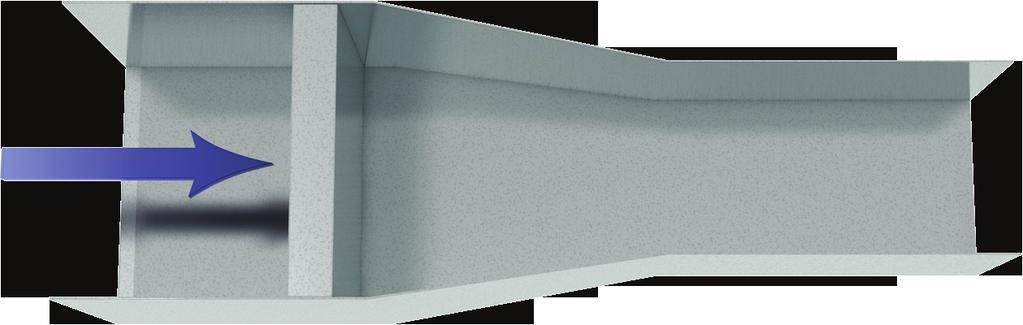
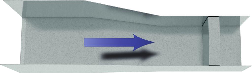
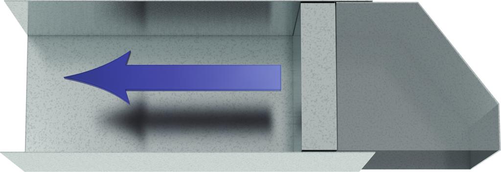
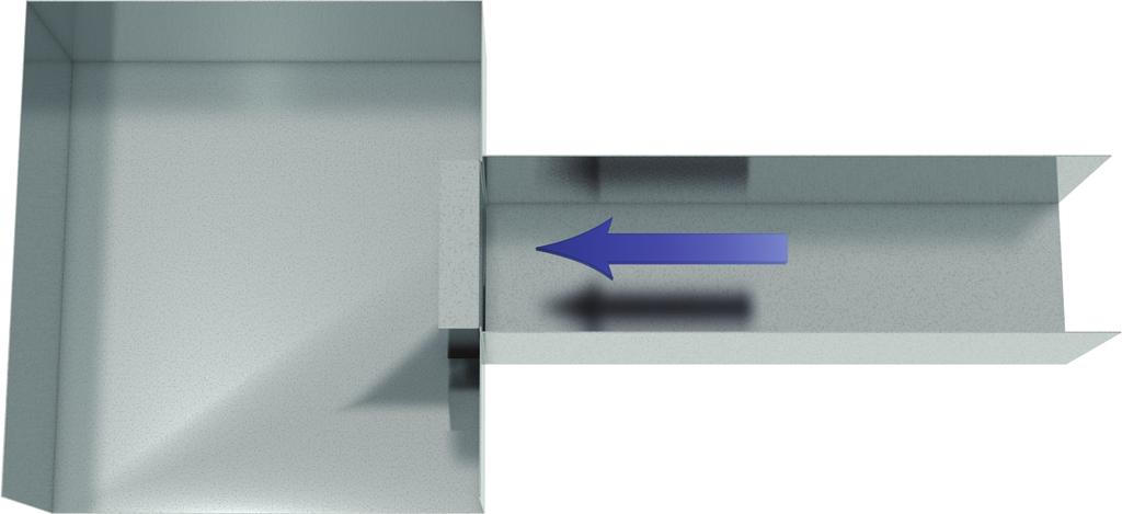
1 Document number AMS & AMD Damper Series for Honeywell Spyder Controller Installation, Operation, and Maintenance Instructions Use this manual when AMS and AMD series dampers were purchased prior to June 1, After June 1, 2015, refer to Document Number This manual is the property of the owner, and is required for future maintenance. Please leave it with the owner when the job is complete. SAFETY WARNING: Improper installation, adjustment, alteration, service or maintenance can cause property damage, injury or death. Read the installation, operating, and maintenance instructions thoroughly before installing or servicing this equipment. Airflow AMS Note: A minimum velocity of 300 fpm (1.5 m/s) is required. AMD-42 RECEIVING AND HANDLING Upon receiving dampers, check for both obvious and hidden damage. If damage is found, record all necessary information on the bill of lading and file a claim with the final carrier. Check to be sure that all parts of the shipment, including accessories, are accounted for. Dampers must be kept dry and clean. Indoor storage and protection from dirt, dust and the weather is highly recommended. Do not store at temperatures in excess of 100 F (37ºC). Due to continuing research, Greenheck reserves the right to change specifications without notice. Pre-Installation Guidelines The basic intent of a proper installation is to secure the AMS & AMD series damper into the opening in such a manner as to prevent distortion and disruption of damper operation. The following items will aid in completing the damper installation in a timely and effective manner. 1) Check the schedules for proper damper locations within the building. Visually inspect the damper for damage. 2) Lift or handle damper using sleeve or frame. Do not lift damper using blades, linkage, actuators, pick-ups, or jackshafting. When handling multiple sections assemblies, use sufficient support to evenly lift at each section mullion (see drawing). Do not drag, step on, apply excessive bending, twisting, or racking. 3) Do not install screws in damper frame that will interfere with unexposed blade linkage and
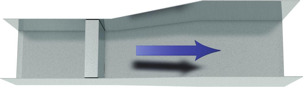
2 prevent damper blades from opening and/or closing. Multi section dampers Attachments Spreader Bar 4) Damper must be installed into duct or opening square and free of twist or other misalignment. Damper must not be squeezed or stretched into duct or opening. Out of square, racked, twisted or misaligned installations can cause excessive leakage and/or torque requirements to exceed damper/actuator design. 5) Damper and actuator must be kept clean, dry and protected from dirt, dust and other foreign materials prior to and after installation. Examples of such foreign materials include but are not limited to: a) Mortar dust b) Drywall dust c) Firesafing materials d) Wall texture e) Paint overspray 6) Damper should be sufficiently covered as to prevent overspray if wall texturing or spray painting will be performed within 5 feet (1.5m) of the damper. Excessive dirt or foreign material deposits on damper can cause excessive leakage and/or torque requirements and inaccurate airflow measurement to exceed damper/actuator design. 7) ACCESS: Suitable access (actuators maintenance, etc.) must be provided for damper inspection and servicing. Where it is not possible to achieve sufficient size access, it will be necessary to install a removable section of duct. Installation- Failure to follow instructions will void all warranties 1. Ensure the AMS or AMD series damper is mounted with airflow straightener upstream of the damper. 2. Duct opening or opening square should measure 1/4 inch (6mm) larger than damper dimension and should be straight and level. 3. Use shims between damper frame and duct opening or opening space to prevent distortion of frame by fasteners holding it in place. Brace at every horizontal mullion and vertically brace at every 8 feet (2.4m) of damper width for strength. Dampers in high velocity (2000 fpm [610m per second]) may require more bracing. Note: Greenheck dampers are specifically designed and engineered for structural integrity based on model and conditions. Attachment, framing, mating flanges, and anchoring of damper assemblies into openings, ductwork, or walls is the responsibility of the installer. Design calculations for these retaining and supporting members should be determined by field engineers for that particular installation. 4. Individual damper sections, as well as entire multiple section assemblies must be completely square and free from racking, twisting, or bending. Measure diagonally from upper corners to opposite lower corners of each section. A C E B D F AF = BE AB = CD Do not twist or bow. Mount damper plumb in the opening. 5. Damper blades, axles, and linkage must operate without binding. Before system operation, cycle dampers after installation to assure proper operation. On multiple section assemblies all sections should open and close simultaneously. 2
3 Installation cont... 6) Installing two section high AMD series together. AMD's more than one section high will be shipped separately in individual sleeves. The high and low pressure ports need to be plumbed together and then plumbed back to the pressure transducer. Damper Sleeve Pressure Transducer Plumb the high pressure parts together Plumb the low pressure parts together Electrical Guidelines Damper Sleeve Electrical and/or pneumatic connections to damper actuators should be made in accordance with wiring and piping diagrams developed in compliance with applicable codes, ordinances and regulations. SAFETY CAUTION! Verify power requirements before wiring actuator. Greenheck is not responsible for any damage to, or failure of the unit caused by incorrect field wiring. SAFETY DANGER! Electrical input may be needed for this equipment. This work should be performed by a qualified electrician. Connect electrical connection to terminal strip as shown on drawing (see figure 1). Setup and Operation for AMS and AMD Series Without Factory Supplied Controller The factory supplied pressure transducer supplies a 0-10 VDC output that is proportional to the pressure measured by the airflow station (see Figure 1). Using the output from the transducer a controller can be programmed to calculate airflow using the formulas: P transducer = (Transducer Output Voltage) * (high Pressure Limit of Transducer)/10 The factory supplied pressure transducer has a high pressure limit of 0.25 in. wg, 1.0 in. wg, or 2 in. wg depending on the size fo the AMD/AMS and the selected maximum calibrated velocity. The value is listed on the transducer and on the labe affixed to the AMD/AMS. CFM = Area * K * (P transducer ) m The K & m values are damper specific factory supplied variables that will be printed on a label on the side of the damper: 24 VAC In 0-10 Vdc output Figure 1 Transducer without factory controller 3
4 Assembled in USA Sales Order: Line: Item Number: AMD x P.O Assy Date: 5/6/10 Qty: 1of 1 Actuator: MS7510A2008 Damper Model: AMD-42 Damper Width: Damper Height: Q = Area * K * P m Q = Airflow (cfm) P = Damper Pressure (in *wc) K = 8,720 m = Area = 4.0 Label 1 Label 2 Setup and Operation for AMS and AMD Series With Factory Supplied Controller 1. Mount the control box higher than the damper to avoid condensation from running back into the pressure transducer. 2. Wire the actuator terminals to the control box terminal strip as shown in figure 1. Wire the actuator power, actuator terminals 1 and 2, to the control box terminals labeled P1 and P2 respectively. Wire the actuator position command, actuator terminal 3, to the control box terminal labeled Plumb the air pressure pickups from the damper to the control box as shown in figure 1. Make sure that the air pressure pickup fitting labeled High is plumbed back to the control box fitting labeled High. Likewise, the air pressure pickup fitting labeled Low should be plumbed back to the control box fitting labeled Low Pressure. 4. Wire the airflow setpoint command (+) to control box terminal 2 and the airflow setpoint command ground (-) to control box terminal 1. Note: The control signal source must have an impedance of less than 2,000 ohms. The correct flow setpoint signal can be calculated based on the following formula: Where: Q = Desired Airflow (cfm) C = Flow Set-point (Vdc or ma) A = Face Area of the damper (ft 2 ) 0-10VDC C = (10/ Max Cal. Velocity) * (Q/A) 2-10VDC C= (8/Max Cal. Velocity) *(Q/A) mA C=(16/max Cal. Velocity)*(Q/A)+4 Example: The building desires 6,000 cfm through a 24 x 24 AMD-42 with 0-10VDC. A= (24*24)/144 = 4 ft 2 C=6,000 / (200 * 4) =7.5 Vdc Factory Controller Terminal Strip Transducer Transformer Terminal Strip Controller Figure 2 wiring diagram with factory controller 4


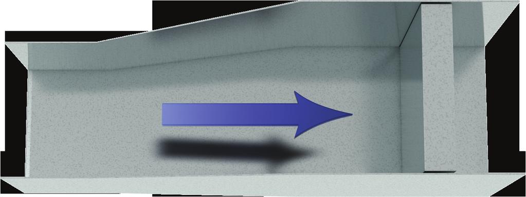
5 Optimal Placement for AMS & AMD Damper Series Fans 3D 1.5D Centrifugal Fan Discharge Centrifugal Fan Inlet 5D Vane Axial Fan Discharge Vane Axial Fan Inlet Elbows 90 Elbow Without Vanes 90 Vaned Elbow 5D Round Sweep Elbow Sweep Elbow 5


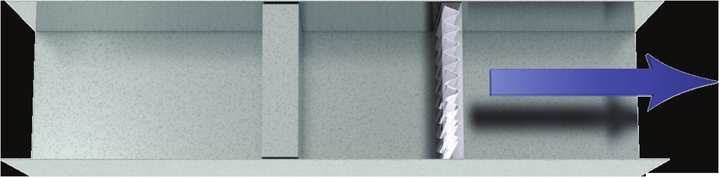
6 Optimal Placement for AMS & AMD Damper Series Dampers 4D D1 D2 Transitions Transition 1 Transition 2 Transition 3 Transition 6 Transition 7 6 Transition 5 Transition 4 Transition 8


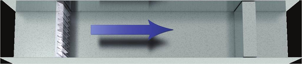
7 Optimal Placement for AMS & AMD Damper Series Takeoffs Branch Takeoff B2A 3D 3D Branch Takeoff 3 Branch Takeoff 1 Branch Takeoff B2B Branch Takeoff 4 Air Handling Units Louver Air Handler with Louver Hood Return Air 7


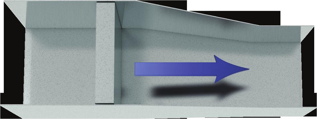
8 Optimal Placement for AMS & AMD Damper Series Air Handling Units... MIN 3D Fan Discharge 2 Fan Discharge 1 Rectangular Duct: D= 4 x Width x Height Circular Duct: D = Duct Diameter Damper Maintenance Greenheck's dampers are designed to be trouble free and hassle free under normal operation. Dampers are to be installed square and straight so as to prevent binding during operation. The following annual damper maintenance suggestions will help to insure proper damper operation and increase the life expectancy of the damper. Foreign Matter Over the course of time, dirt and grime may collect on damper surfaces. The damper surfaces should be cleaned to prevent hindrance to airflow. Moving Parts Make sure that parts such as linkage, bearings, blades, etc. that are intended to move freely, can do so. Lubricating these components can prevent possible rusting and unnecessary friction increase. Use only a moli-spray oil or similar graphite based oil as regular lubricating oil will attract dirt. Bearings. Synthetic, oil impregnated, and ball bearings (without grease fittings) do not require lubrication. Ball bearings with grease fittings require only minimal grease. Closure Remove foreign materials that may be interfering with blade closure or effective sealing of the blades with each other or with the frame. Operation While operating the damper through its full cycle, check to see that the blades open and close properly. If there is a problem, check for loose linkage, especially at the actuator. Tighten the linkage where required. Our Commitment As a result of our commitment to continuous improvement, Greenheck reserves the right to change specifications without notice. Specific Greenheck product warrantees can be located on greenheck.com within the product area tabs and listed in the Library under Warrantees. Phone: (715) Fax: (715) gfcinfo@greenheck.com Website: AMS & AMD, Rev. 1, May 2015 Copyright 2015 Greenheck Fan Corporation
Installation, Operation, and Maintenance Instructions
 Document Number 463384 VCD, FBH & FBV MODELS Vertical and Horizontal Mount Installation, Operation, and Maintenance Instructions This manual is the property of the owner, and is required for future maintenance.
Installation, Operation and Maintenance Manual
 Document 483509 VCD, FBH & FBV Models Vertical and Horizontal Mount Installation, Operation and Maintenance Manual Please read and save these instructions for future reference. Read carefully before attempting
Installation, Operation and Maintenance Manual
 Document 461338 SMOKE DAMPERS SMD-XXX, SMD-XXXEF, SMD-XXXM, SMD-XXXV, SESMD-XXX, SSSMD-XXX, SMDR-XXX, SESMDR-XXX, and SSSMDR-XXX Series Leakage Rated Smoke Dampers Vertical and Horizontal Mount Installation,
Installation, Operation and Maintenance Manual
 Document 474916 HBS Series Installation, Operation and Maintenance Manual Please read and save these instructions for future reference. Read carefully before attempting to assemble, install, operate or
Installation, Operation and Maintenance Manual
 Installation, Operation and Maintenance Manual Document 483514 SMOKE DAMPERS SMD-XXX and SMDR-XXX Series Leakage Rated Smoke Dampers Vertical and Horizontal Mount Please read and save these instructions
The IAQ50 Air Damper/Monitor Installation and Maintenance Manual
 The IAQ50 Air Damper/Monitor Installation and Maintenance Manual RUSKIN MANUFACTURING 3900 Dr. Greaves Road Kansas City, Missouri 64030-1183 U.S.A. ! WARNING DO NOT TAMPER WITH (REMOVE, REPLACE, RELOCATE
Installation, Operation and Maintenance Manual
 Document Number 478799 AMD-xx-TD Series Installation, Operation and Maintenance Manual Please read and save these instructions for future reference. Read carefully before attempting to assemble, install,
Installation, Operation and Maintenance Instructions
 Document Number 474094 CRD-1WT Ceiling Radiation for Wood Truss Application Installation, Operation and Maintenance Instructions Receiving and Handling Upon receiving dampers, check for both obvious and
AMD-42V Air Measuring Station with VCD-42V Control Damper
 Application and Design Construction Standard Optional Frame Material Galvanized Steel - Frame Material Thickness 16 ga. (1.5mm) 12 ga. (2.7mm) 14 ga. (2mm) Frame Type 5 in. x 1 in. hat channel - Blade
AMD-42 Air Measuring Station with VCD-42 Control Damper
 Application and Design W x H Construction Standard Optional Frame Material Galvanized Steel - Frame Material Thickness External Minimum Size 16 ga. (1.5mm) Internal Single Section Maximum Size Multiple
AMD-33. Air Measuring Station with VCD-33 Control Damper. Application and Design. Features & Control Options
 Application and Design The combines the functionality of an accurate airflow measuring station and a low leakage control damper into one compact assembly that both measures and regulates airflow volumes
Air Measuring Products. AMS Thermal Dispersion Pressure Differential
 Air Measuring Products AMS Thermal Dispersion Pressure Differential August 2014 1 Airflow Measuring Technologies Greenheck airflow measuring products are available with either differential pressure based
AMD-33 Air Measuring Station with VCD-33 Control Damper
 Application and Design Construction Standard Optional Frame Material Galvanized Steel - Frame Material Thickness 16 ga. (1.5mm) 12 ga. (2.7mm) Frame Type 5 in. x 1 in. hat channel - Blade Material Galvanized
RECEIVING AND HANDLING INSTALLATION SUPPLEMENTS WARRANTY SAFETY WARNING:
 Part #461336 Installation,Operation and Maintenance Instructions for FSD-XXX, DFD-XXX,DFDTF-XXX CFSD-XXX,SEDFD-XXX, SEFSD-XXX, IMO-XXX, AND SSFSD-XXX SERIES 1 1 2 and 3 Hour Fire & Combination Fire Smoke
Part # Installation,Operation and Maintenance Instructions
 Part #461336 Installation,Operation and Maintenance Instructions for FSD-xxX, DFD-XXX, DFDTF-XXX CFSD-XXX, SEDFD-XXX, SEFSD-XXX, IMO-XXX, and SSFSD-XXX Series 1 1 2 and 3 Hour Fire & Combination Fire Smoke
Air Quality Solutions
 Air Quality Solutions Installation & Maintenance Manual Model: IAQ50X Air Measuring Station Indoor Air Quality Damper II-IAQ50X-818/Replaces II-IAQ50X-612 ALL STATED SPECIFICATIONS ARE SUBJECT TO CHANGE
MODELS TSX AND TSX-S SINGLE DUCT ROUND AIR TERMINALS
 MODELS TSX AND TSX-S SINGLE DUCT ROUND AIR TERMINALS INSTALLATION OPERATION & MAINTENANCE New Release Form 130.13-NOM4 (908) In conjunction with the use of these instructions, obtain and refer to the construction,
MODELS SGX AND SSX SINGLE DUCT ROUND AIR TERMINALS
 BY JOHNSON CONTROLS INSTALLATION OPERATION & MAINTENANCE MODELS SGX AND SSX SINGLE DUCT ROUND AIR TERMINALS New Release Form ET130.13-NOM4 (908) In conjunction with the use of these instructions, obtain
Air Measuring Products AMD AMS IAQ
 Air Measuring Products AMD AMS IAQ January 1 2012 Air Measuring Products Why is outside air measurement important? There are many significant benefits to monitoring outside air volumes. By measuring the
Centrifugal Cabinet Fans Model BCF Belt Drive Low-Profile
 Centrifugal Cabinet s BCF Belt Drive Low-Profile May 2007 BCF Belt Drive Cabinet s Greenheck belt drive low-profile cabinet fans, BCF, are designed for efficiency and reliability in supply, exhaust or
CCS Zone/Bypass Damper Assembly
 Code No. LIT-1900539 Issued July 15, 2011 UZR-xx-x, UBR-xx-x, UZD-0xxX0xx-x, UBD-0xxX0xx-x CCS Zone/Bypass Damper Assembly Description The Commercial Comfort System (CCS) Zone/Bypass Damper are zone control
Centrifugal Cabinet Fans Model BCF. Belt Drive Low-Profile
 Centrifugal Cabinet s BCF Belt Drive Low-Profile November 204 BCF Centrifugal Cabinet Contents Standard Construction Features... 3 Options and Accessories... 4 Filter and Mixing Box Data... 5 Typical Installations...
AMD-42-TD. Thermal Dispersion Air Measuring Station with VCD-42 Control Damper. Application and Design. Ratings. Features and Control Options
 Application and Design Thermal Dispersion Air Measuring Station with VCD-42 Control Damper The combines the functionality of a highly accurate thermal dispersion airflow measuring station and a low leakage
FOR USE IN SOLUTION AIR HANDLING UNITS
 AMS-60 AIRFLOW MONITORING DEVICE APPLICATION GUIDE Supersedes: NOTHING Form 102.20-AG1 (303) FOR USE IN SOLUTION AIR HANDLING UNITS GENERAL The YORK AMS-60 is an airflow monitoring device which combines
Model SMD-302M. Modulating Smoke Damper. Application. Steel Airfoil Blades UL 555S Leakage Class II. Ratings. Size Limitations.
 Model Application The is a leakage rated modulating smoke damper with airfoil blades for operational closure in emergency smoke control situations. This model serves the function of both a control damper
Installation, Operation and Maintenance Manual
 Document 458295 Automatic Fire Damper Installation, Operation and Maintenance Manual Please read and save these instructions for future reference. Read carefully before attempting to assemble, install,
AMD-23-TD. Thermal Dispersion Air Measuring Station with VCD-23 Control Damper. Application. Ratings. Features and Options
 Application Thermal Dispersion Air Measuring Station with VCD-23 Control Damper The combines the functionality of a highly accurate thermal dispersion airflow measuring station and a low leakage control
Introduction to Johnson Controls Dampers
 Damper and Actuator Product Guide 268.1 Damper Engineering Section Product Bulletin Issue Date 1297 Introduction to Johnson Controls Dampers For over 100 years, Johnson Controls has been the industry leader
Table of Contents. Page 2 Page 2 Page 2 Page 2 Page 3 Page 3 Page 3 Page 3 Page 3 Page 4 Page 4 Page 4 Page 5 Page 5 Page 5
 -02 - Location and Mounting: AirflowMonitoringStation Table of Contents #1 - Right Angle wo/turning Vanes Mounting #2 - Right Angle w/turning Vanes Mounting #3 - Right Angle w/rounded Elbow Mounting #4
Model DFD-150. Dynamic Rated Fire Damper 11/2 Hour Fire Resistance Rating. Application. Ratings. Optional Features
 Application Model is approved for use in walls, floors, and partitions with fire resistance ratings less than 3 hours. This model carries a 1 1 2 hour UL fire damper label. UL555 classifies dynamic rated
NJK Precision Product NJK-02 Sensor Installation Guide
 Precision -02 Sensor 2017 Product Line Precision Product Table of Contents Precision Company Overview - Page 2-02 Installation Guidelines - Page 3-02 Recommended Installations - Page 5-02 Non-Recommended
Model VCD-18. Ratings. Blade Operation. Size Limitations. Features & Options
 Application and Design The series is a general purpose, low leakage control damper intended for application in low pressure and velocity systems. atings Pressure: 2 in. wg (.5 kpa) - pressure differential.
YCCS Zone/Bypass Damper Assembly
 YCCS Zone/Bypass Damper Assembly UZR-xx-x, UBR-xx-x, UZD-0xxX0xx-x, UBD-0xxX0xx-x The York Commercial Comfort System (YCCS) Zone/Bypass Damper are zone control and pressure control devices that include
Model VCD-20V. 3V Vertical Control Damper. Application and Design. Ratings (See page 4 for specific limitations) Flange Options.
 Flange Options.") Application and Design The series is a vertical blade general purpose damper for application as an automatic control or manual balancing damper. This model is intended for application in low to medium
Application and Design The series is a vertical blade general purpose damper for application as an automatic control or manual balancing damper. This model is intended for application in low to medium
Model VCD-20. Control Damper. Application. 3V Blade. Ratings. Flange Options. Size Limitations. Blade Operation. Features and Options
 Application The series is a general purpose control damper for applications as an automatic control or manual balancing damper with low to medium pressure and velocity systems. A wide range of electric
YCCS Zone/Bypass Damper Assembly
 YCCS Zone/Bypass Damper Assembly UZR-xx-x, UBR-xx-x, UZD-0xxX0xx-x, UBD-0xxX0xx-x The York Commercial Comfort System (YCCS) Zone/Bypass Damper Assemblies are zone control and pressure control devices that
Model CFSD-211. Corridor Ceiling FIRE SMOKE DAMPER Steel 3V Blades UL 555S Leakage Class I
 Application and Design Model is a combination fire smoke damper that is UL classified to protect corridor ceiling penetrations as required by the Uniform Building Code. This model s operational ratings
READ AND SAVE THESE INSTRUCTIONS
 READ AND SAVE THESE INSTRUCTIONS Part #469003 Model Vektor -H Installation Operation and Maintenance Manual for Vektor-H Laboratory Exhaust System Receiving Greenheck model Vektor-H fans are thoroughly
Model VCD-40. Extruded Airfoil Blade Control Damper Narrowline Frame Construction. Application. Ratings. Flange Options.
 Model Application The is a low leakage high performance control damper with extruded aluminum airfoil blades. Blades are completely contained within the frame allowing the damper to be directly mounted
Model SSFSD-211. Combination Fire Smoke Damper 304 Stainless Steel 3V Blades UL 555S Leakage Class I UL Hour Fire Resistance Rating
 R Model Application Model is a 304SS combination fire smoke damper with 3V style blades. The is qualified to 2,000 fpm (10.2 m/s) and 6 in. wg (1.5 kpa). This damper may be installed vertically (with blades
Model DFD-230 Multi-Blade Fire Damper Steel 3V Blades UL555 3 Hour Fire Resistance Rating
 Application Model is a multi-blade fire damper with 3V style blades. The has been qualified to 4000 fpm (20.3 m/s) and 10 in. wg (2.5 kpa) for dynamic closure in emergency fire situations. Model may be
MOTORIZED VOLUME DAMPER
 MOTORIZED VOLUME DAMPER 1 a perfect partner in performance... Our Product Ranges Dampers 1 Fire Dampers 2 Fire / Smoke Dampers 3 Volume Control Dampers 4 Motorized Control Dampers 5 Pressure Relief Dampers
Model VCD-20 3V CONTROL DAMPER
 R Application and Design The series is a ruggedly built general purpose damper for application as an automatic control or manual balancing damper. This model is intended for application in low to medium
MANUAL INSTALLATION. Venturi FX. VFX Series. v100 Issue Date: 11/22/ Price Industries Limited. All rights reserved.
 MANUAL INSTALLATION Venturi FX VFX Series v100 Issue Date: 11/22/16 2016 Price Industries Limited. All rights reserved. TABLE OF CONTENTS Product Overview Safety Precautions... 1 Caution to Contractors...1
Model FSD-331. Combination Fire Smoke Dampers. Application. Ratings. Features
 Application Model is a high performance combination fire smoke damper with Class I leakage. High strength airfoil blades ensure the lowest resistance to airflow in HVAC systems with velocities to 4000
Model SMD-301. Smoke Damper Steel Airfoil Blades UL 555S Leakage Class I. Application. Ratings. Size Limitations. Features
 Model Application The is a leakage rated smoke damper with airfoil blades for operational closure in emergency smoke control situations. This model serves the function of both a control damper and smoke
WD-300 Series. Backdraft Damper Vertical Mount - Horizontal Airflow. Application and Design. Ratings. Frame Styles. Size Limitations.
 Application and Design The WD300 series dampers are designed to prevent reverse airflow in horizontal exhaust applications. The WD300 features a pressure sensitive blade design that opens and remains open
MODEL 8682 SUREFLOW ADAPTIVE OFFSET CONTROLLER
 MODEL 8682 SUREFLOW ADAPTIVE OFFSET CONTROLLER INSTALLATION INSTRUCTIONS WARNING: The Model 8682 Adaptive Offset Controller must be wired to 24 VAC only. Wiring the unit to 110 VAC will cause serious unit
VCD-23. Low Leakage CONTROL DAMPER
 Application and Design The series is a ruggedly built low leakage control damper intended for application in low to medium pressure and velocity systems. A wide range of electric and pneumatic actuators
VCD-23. Flange Options. Size Limitations
 Application and Design The series is a ruggedly built low leakage control damper intended for application in low to medium pressure and velocity systems. A wide range of electric and pneumatic actuators
Baked Enamel, Epoxy, Hi Pro Polyester, Industrial Epoxy, Kynar/Hylar (70%) Permatector. Single or Reverse Flange 8 x 6 (203 x 178)
 Permatector. Single or Reverse Flange 8 x 6 (203 x 178)") Application and Design The is an extremely low leakage damper designed to meet the highest standards established for commercial control dampers. The is intended for application in medium to high pressure
Application and Design The is an extremely low leakage damper designed to meet the highest standards established for commercial control dampers. The is intended for application in medium to high pressure
Centrifugal Cabinet Fans Model BDF. Belt Drive Duct Fan
 Centrifugal Cabinet s BDF Belt Drive Duct July 007 BDF Belt Drive Duct s Greenheck s Belt Drive Duct s, BDF, provide the industry s best performance and durability. BDF is carefully engineered for efficiency
Laboratory Exhaust Systems
 Laboratory Exhaust Systems Vektor -HS, Vektor -MS and Vektor -CS with Variable Geometry Nozzle September 017 Vektor -HS, Vektor -MS and Vektor -CS Greenheck s Variable Geometry Nozzle exhaust systems allow
VCD-23 Low Leakage CONTROL DAMPER
 Application and Design The series is a ruggedly built low leakage control damper intended for application in low to medium pressure and velocity systems. A wide range of electric actuators are available.
HCD-135. Industrial Control Damper. Application and Design. Ratings (see page 2 and 3 for specific limitations) Standard Construction.
 Standard Construction.") Application and Design Model is a heavy duty industrial control damper with a flanged frame. It is designed to control airflow and provide shut off in HVAC or industrial process control systems. A variety
Application and Design Model is a heavy duty industrial control damper with a flanged frame. It is designed to control airflow and provide shut off in HVAC or industrial process control systems. A variety
HCD-230 Industrial Control Damper
 Application and Design Model is a heavy duty industrial control damper with a flanged frame. It is designed to control airflow and provide shut off in HVAC or industrial process control systems. A variety
Model DFD-150. Dynamic Rated Fire Damper 11/2 Hour Fire Resistance Rating. Application. Ratings. Optional Features
 Application Model is approved for use in walls, floors, and partitions with fire resistance ratings less than 3 hours. This model carries a 1 1 2 hour UL fire damper label. UL555 classifies dynamic rated
Tube Axial Inline Fans
 Tube Axial Inline Fans Models TDI & TBI-CA Level 3 with Cast Aluminum Propeller Direct & Belt Drive Clean Air or Fume Exhaust July 2011 Features Tube Axial Inline Fans Greenheck s tube axial fans are the
PC-125x Counter-Balanced Backdraft Damper
 PC-15x Counter-Balanced Backdraft Damper Product Bulletin Code No. LIT-101180 Issued April 7, 015 Refer to the QuickLIT Web site for the most up-to-date version of this document. Since 1885, Johnson Controls
Centrifugal Roof Supply Fans Models RSF and RSFP. Forward Curved
 Centrifugal Roof Supply Fans Models and Forward Curved April 2008 Centrifugal Filtered Roof Supply Fan When you buy a Greenheck model or, you receive a fan with the industry s best performance and durability
Table of Contents. Page 2 Page 2 Page 2 Page 2 Page 3 Page 3 Page 3 Page 3 Page 3 Page 4 Page 4 Page 4 Page 5 Page 5 Page 5
 -02 - Location and Mounting: AirflowMonitoringStation Table of Contents #1 - Right Angle wo/turning Vanes Mounting #2 - Right Angle w/turning Vanes Mounting #3 - Right Angle w/rounded Elbow Mounting #4
SMD-201M. Application. Modulating Smoke Dampers Steel 3V Blades UL 555S Leakage Class I. Ratings. Operational Rating. Size Limitations.
 Application Model is a leakage rated modulating smoke damper with 3V style blades. The has been qualified to 2,000 fpm (10.2 m/s) and 6 in. wg (1.5 kpa) for operational closure in emergency smoke control
Model DFD-350. Dynamic Rated Fire Damper 3 Hour Fire Resistance Rating. Application. Ratings. Optional Features
 Application Model is approved for use in walls, floors, and partitions with fire resistance ratings of hours or more. This model carries a hour UL fire damper label. UL 555 classifies dynamic rated fire
Model FSD-211. Application. Combination Fire Smoke Damper Steel 3V Blades UL 555S Leakage Class I UL /2 Hour Fire Resistance Rating.
 Application Model is a combination fire smoke damper with 3V style blades. This model is designed for operation and dynamic closure in emergency fire smoke situations. It is rated for airflow and leakage
Centrifugal Roof Supply Fans Models RSF and RSFP. Forward Curved
 Centrifugal Roof Supply Fans Models and Forward Curved B U I L D I N G V A L U E I N A I R. April 2008 Centrifugal Filtered Roof Supply Fan When you buy a Greenheck model or, you receive a fan with the
INSTALLATION & OPERATION MANUAL. Fan Powered Terminals VAV TERMINALS. Redefine your comfort zone.
 INSTALLATION & OPERATION MANUAL Fan Powered Terminals VAV TERMINALS IOM FAN POWERED TERMINALS Receiving Inspection After unpacking the terminal, check it for shipping damage. If any shipping damage is
Model VCD-43 Extruded Airfoil Blade Control Damper
 Application and Design The is an extremely low leakage damper designed to meet the highest standards established for commercial control dampers. The is intended for application in medium to high pressure
SMD-201. Application. Smoke Dampers Steel 3V Blades UL 555S Leakage Class I. Ratings. Operational Rating. Size Limitations.
 Application Model is a leakage rated smoke damper with 3V style blades. The has been qualified to 2,000 fpm (10.2 m/s) and 6 in. wg (1.5 kpa) for operational closure in emergency smoke control situations.
Utility Distribution System
 READ AND SAVE THESE INSTRUCTIONS Utility Distribution System Installation, Operation and Maintenance Manual Warning!! Improper installation, adjustment, alteration, service or maintenance can cause property
Model VCD-34. Low Leakage Insulated Airfoil CONTROL DAMPER. Ratings (See page 3 for specific limitations) Flange Options.
 Flange Options.") Application and Design The Series is a ruggedly built low leakage control damper with thermally insulated blades. The is intended for application in medium pressure and velocity systems. This model also
Application and Design The Series is a ruggedly built low leakage control damper with thermally insulated blades. The is intended for application in medium pressure and velocity systems. This model also
CONTROL DAMPERS. Models 1810 & Model Model Model 1370
 CONTROL DAMPERS CONTROL DAMPERS MODELS 1810 & 1820 MANUAL ALANCING DAMPERS STEEL Models 1810 and 1820 have been engineering and designed for manual balancing applications in low to medium pressure and
Model SEVCD-33. Low Leakage Airfoil Control Damper. Application and Design. Ratings (See page 3 for specific limitations) Blade Operation
 Blade Operation") Application and Design The is a severe environment 316SS ultra low leakage control damper with rugged stainless steel airfoil blades designed to meet the highest standards established for commercial control
Application and Design The is a severe environment 316SS ultra low leakage control damper with rugged stainless steel airfoil blades designed to meet the highest standards established for commercial control
Model FSD-331 Combination Fire Smoke Dampers
 R APPLICATION Model is a high performance combination fire smoke damper with class I leakage. High strength airfoil blades ensure the lowest resistance to airflow in HVAC systems with velocities to 4000
HVAC Control & Balancing Dampers
 HVAC Control & Balancing Dampers Models VCD, MBD and RBD Selection Construction Performance H* W* 1June 2017 Design and Construction Features Bearing Shaft Extension Jamb Seal Commercial Control Dampers
Installation, Operation and Maintenance Manual
 Document 482393 Model MSF Direct Drive Supply Fan Installation, Operation and Maintenance Manual Please read and save these instructions for future reference. Read carefully before attempting to assemble,
Model FSD-212. Combination FIRE SMOKE DAMPERS
 R APPLICATION Model is a combination fire smoke damper with 3V style blades. The has been qualified to 2000 fpm (10.2 m/s) and 6 in. wg (1.5 kpa) for operation and dynamic closure in emergency fire smoke
WD-200 Series. Model WD-220 Flange Opposite Motor. Model WD-210 Flange on Motor Side. Model WD-200 No Flange. Motorized Backdraft Damper.
 Application The WD200 series are electrically motorized backdraft dampers that open when energized and spring return close when deenergized. The WD200 series are for horizontal or vertical mounting. Primary
Safety & Installation Instructions
 Model 8120A & 8126A Digital Ventilation Controller Safety & Installation Instructions READ AND SAVE THESE INSTRUCTIONS Table of contents Safety Instructions... 3 Specifications... 4 Overview... 4 Mounting
First Inline fan in the industry to be UL/cUL Listed Power Ventilator for Smoke Control Systems
 Medium Pressure Axial Fans Model TBI-FS Levels 3, 4 & 5 with Fabricated Steel Propeller Belt Drive Inline or Roof Mounted Upblast Clean Air or Fume Exhaust High Temperature Process Exhaust Emergency Smoke
Smoke Dampers. Installation Instructions
 Smoke Dampers Installation Instructions Installation Details 1. Dampers should be installed to provide proper operation and performance. They should be installed to permit them to maintain their shape
VCD-43V. Vertical Airfoil Blade Control Damper. Application and Design. Ratings. Size Limitations. Features and Options: Pressure:
 Application and Design is a low leakage damper with vertical blade orientation designed to meet the highest standards established for commercial control dampers. The is intended for application in medium
CONTROL DAMPERS. Model Model 1370CB. Model 1380CB. Model 1390CB B7
 CONTROL DAMPERS MODEL 1380 HIGH PERFORMANCE ACKDRAFT DAMPER EXTRUDED ALUMINUM HEAVY DUTY Model 1380 is a high performance extruded aluminum gravity operated backdraft damper for use in medium to heavy
HVAC Control & Balancing Dampers
 HVAC Control & Balancing Dampers Models VCD, MBD and RBD Selection Construction Performance H* W* August 1 2013 HVAC Control and Balancing Dampers Commercial Control Dampers are used in buildings to regulate
CFSD Series. Product Description
 COMBINATION FIRE AND SMOKE DAMPER 1-1/2 HR LEAKAGE RESISTANCE CLASS II 250 O F FILE NO: R22165 Product Description Combination Fire / Smoke dampers provide an automatic means of localizing areas of smoke
Installation, Operation and Maintenance Manual
 Document 479288 Installation, Operation and Maintenance Manual Please read and save these instructions for future reference. Read carefully before attempting to assemble, install, operate or maintain the
General Safety Information. Document KSFB and KSFD DANGER CAUTION WARNING! DBC DB3. Horizontal
 Document 471553 KSFB and KSFD Installation, Operation and Maintenance Manual Please read and save these instructions for future reference. Read carefully before attempting to assemble, install, operate
Model FSD-211. Combination FIRE SMOKE DAMPERS Steel 3-V Blades UL 555S Leakage Class I UL Hour Fire Resistance Rating
 R APPLICATION Model FSD-211 is a combination fire smoke damper with 3V style blades. The FSD-211 has been qualified to 2000 fpm (10.2 m/s) and 6 in. wg (1.5 kpa) for operation and dynamic closure in emergency
MODEL 8636 / 8636-LN / 8636-BAC SUREFLOW ROOM PRESSURE CONTROLLER
 MODEL 8636 / 8636-LN / 8636-BAC SUREFLOW ROOM PRESSURE CONTROLLER INSTALLATION INSTRUCTIONS The Model 8636 Room Pressure Controller must be wired to 24 VAC only. Wiring the unit to 110 VAC will cause serious
INSTALLATION, OPERATION AND MAINTENANCE MANUAL WALL EXHAUST FANS BELT DRIVE XBL FANS
 INSTALLATION, OPERATION AND MAINTENANCE MANUAL WALL EXHAUST FANS BELT DRIVE XBL FANS The purpose of this manual is to aid in the proper installation and operation of the fans. These instructions are intended
FBV-43. Vertical Face & Bypass Control Damper Ultra Low Leakage Aluminum Frame Construction. Application and Design. Size Limitations.
 Application and Design The is a vertical style face and bypass low leakage damper. This model is intended for application in medium to high pressure and velocity systems. Smooth profile extruded aluminum
High Performance Axial Fans
 High Performance Axial Fans Model RA Standard and High Temperature High Efficiencies Low Sound January 2014 High Performance Axial Fans Greenheck s model RA, high performance, direct-driven axial fans,
INSTALLATION, OPERATION AND MAINTENANCE MANUAL WALL EXHAUST FANS BELT & DIRECT DRIVE XB, HV, HVA, ADD, DDS, DDP
 INSTALLATION, OPERATION AND MAINTENANCE MANUAL WALL EXHAUST FANS BELT & DIRECT DRIVE XB, HV, HVA, ADD, DDS, DDP The purpose of this manual is to aid in the proper installation and operation of the fans.
Matrix APAX. 380V-415V 50Hz TECHNICAL REFERENCE MANUAL
 Matrix APAX 380V-415V 50Hz TECHNICAL REFERENCE MANUAL WARNING High Voltage! Only a qualified electrician can carry out the electrical installation of this filter. Quick Reference ❶ Performance Data Pages
High Frequency SineWave Guardian TM
 High Frequency SineWave Guardian TM 380V 480V INSTALLATION GUIDE FORM: SHF-IG-E REL. January 2018 REV. 002 2018 MTE Corporation High Voltage! Only a qualified electrician can carry out the electrical installation
Jet Fans. Instruction Manual READ AND SAVE THESE INSTRUCTIONS WARRANTY
 Jet Fans Instruction Manual READ AND SAVE THESE INSTRUCTIONS WARRANTY All Leader Fan products are guaranteed to be free from defects of workmanship or material and to function satisfactorily when properly
Installation, Operation and Maintenance Manual
 Document 473681 Vari-Green Motor and Controls Installation, Operation and Maintenance Manual Please read and save these instructions for future reference. Read carefully before attempting to assemble,
PIM Pressure Independence Module
 PIM Pressure Independence Module PIM : Product Overview BENEFITS AT A GLANCE QUIET VAV DIFFUSER OPERATION The PIM Pressure Independence Module is a modulating static pressure controller/actuator that allows
Direct Gas-Fired Heating
 Direct Gas-Fired Heating Model DG 800 to 15,000 cfm Up to 1,600,000 BTU/hr Optional Evaporative Cooling January 2005 PRODUCT FEATURES Model DG Direct Gas-Fired Make-Up Air Unit The Greenheck model DG is
for Untempered - Make-Up Air Units
 Part # 457646 Installation, Operation, and Maintenance Instructions for Untempered - Make-Up ir Units Table of Contents Installation............................. 2-5 Troubleshooting..........................
Slide Gates INSTALLATION, OPERATION & MAINTENANCE INSTRUCTIONS. 295-E-002 Effective
 295-E-002 Effective 7-1-2013 Slide Gates INSTALLATION, OPERATION & MAINTENANCE INSTRUCTIONS Your Source for Bulk Handling/Air Process Equipment Wm. W. Meyer & Sons, Inc. 1700 Franklin Blvd Libertyville,