IFS Installation Instructions
|
|
|
- Noreen Carr
- 6 years ago
- Views:
Transcription
 Installation Revision Level: Effective Date: July 21th, 2015 Originator:")

1 Wipe Out Enterprises Inc. Work Instructions Document # WOEI-0009 Independent Front Suspension (IFS) Installation Revision Level: Effective Date: July 21th, 2015 Originator: Thomas Ludwig Approved Date: August 27 th, 2015 (DAW) PURPOSE: IFS Installation Instructions TOOLS: Welding Equipment - (Welder, Welding Helmet, Cutting Wheel, etc.) Tape Measure Tubing Notcher Jegs Part #049-ALL10411 IFS Kit (See Picture A ) A1 Upper Shock Mount Qty (2) A2 Wheel Hub Qty (2) A3 Outer Tie Rod Qty (2) A4- Spindle Steering Knuckle Assembly Qty (2) A5- A -Arm Frame Mount Structure - Qty (2) 1 P a g e
 A9 Lower A -Arm Qty (2)")
 Qty (1) 2 P a g")
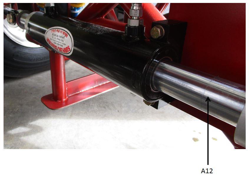
2 A6 Spindle Pivot Qty (2) A7 Upper A -Arm Qty (2) A8 Steering Arms Qty (4) A9 Lower A -Arm Qty (2) A10 Coil-Over Shocks Qty (4) A11 Springs Qty (4) A12 Steering Cylinder (Optional) Qty (1) 2 P a g e

3 Picture A 3 P a g e

4 IFS Installation Instructions: Notes: ***Measurements in these instructions are based on a 15 Diameter Tire (Size 35PSI) and frame width of 22 across the top, if you have different tires diameters and frame width please contact Wipe Out Enterprises Inc. for additional information.*** 1) Tractor must be placed on level surface 2) Set rear tire pressure as if you were setting tractor up to go a pulling event. 3) Remove Fuel/Water Tanks, Wiring, plumbing and etc. from front end of frame. 4) You will need to support front end of frame at desired ride height and place on jack-stands. (See Picture B ) Picture B 5) Center-Line of front axle needs to be determined, if unsure take straight-edge and mark both sides of front axle and centerline will be located half-way between marks. 6) From axle centerline make a mark on the Frame 6 Forward and 6 to the rear. These marks represent the center of the tubes on the A -Arm frame mount structure. You need to measure from the floor to the bottom of the frame at the rear mark, and then you need to subtract 11-5/8 to determine the distance from the frame to lower A -Arm pivot point. From floor to center of lower A -Arm mount should be 11-5/8 (See Picture C ) 4 P a g e

 ***This might change depending on your frame width, measurement is for a 22 Wide Frame*** a.")
5 Picture C 7) Cut A -Arm frame mount structure to determined length from lower A -Arm pivot to top of tubing. a. Cut lower A -Arm frame to achieve the 4 Max distance at ride height. 8) Tack weld A -Arm frame mount structures to bottom of frame, maintaining the width between the lower A -Arm pivots at approx. 24-1/2 to 25-1/2 (See Picture D ) ***This might change depending on your frame width, measurement is for a 22 Wide Frame*** a. A -Arm frame mount structures need to be parallel to one of another and perpendicular to floor. Picture D 5 P a g e
 Bracing is required on front and rear A -Arm Frame Mount Structures.")
6 9) Build X Bracing between A -Arm frame mount structure and tack weld into place, bracing should start in-line with bottom A -Arm Pivot and run to opposite side as high as you can without interfering with any other components. (See Picture E and X Frame highlighted in Picture) Bracing is required on front and rear A -Arm Frame Mount Structures. Picture E 10) Side bracing is required, needs to start at bottom front and extend towards rear of frame. (See Picture F ) 6 P a g e


7 Picture F 11) Upper Shock Mount needs to be located on outer frame rail approx. 15 above lower A - Arm Pivot bracket. Upper mounts need to be located straight above lower A Arm Shock brackets and tack weld in place. (See Picture G ) Picture G 7 P a g e
 Picture H 13) Install Upper and Lower A Arms (Parts A7 & A9) along with coil-over, spindle steering knuckle assembly and spindle pivot.")
8 12) Locate Steering Cylinder, center of steering cylinder body ( X ) should be centered between Y and Z lines. Center of Steering Cylinder Ram ( A ) should be centered between B and C lines. (See Picture H ) Picture H 13) Install Upper and Lower A Arms (Parts A7 & A9) along with coil-over, spindle steering knuckle assembly and spindle pivot. After installed move components to verify that there is no binding between the components. Also verify that the ski s hit the ground before the shocks bottom out. 14) If you are satisfied with the test fit from step #12 then finish welding all the components complete. If not make adjustments as needed and then finish welding the components. 15) Once finish welding is completed, we recommend that components be painted before final assembly. 16) Assemble components as in step #12 and also install springs on shocks. 17) Put Front tires back on tractor and remove jack stands 18) Place weights on tractor, as if you were setting tractor up for a pulling event. 19) To achieve desired ride height, the nut located under the spring will need to be adjusted. To make adjustments, tractors front wheels will need to be jacked up off the ground. 20) The Standard kit comes with 500 pound springs, if overall compressed spring length is less than 5-5/8 then springs will need to be upgraded to either 600 or 650 pound springs. 21) Once springs have been verified, the A -Arms will need to be adjusted so the front wheels are straight vertically. When you check this the tractor needs to be sitting on the ground with the weights in place as you were going to a pulling event. 8 P a g e


9 22) Steering cylinder needs to be adjusted so the same amount or ram is showing outside of the steering cylinder body, then adjust Heiman bearings so the center to center distance is the same as the A Arm Pivots. (See Picture I ) Picture I 23) With steering cylinder still centered, place a string past the rear tire to create a straight line running past front tire. Take a measurement from string to edge of from rim, make adjustments to outer Heiman bearings on outer tie-rod to achieve parallelism with rear tire. (See Picture J & K ) Picture J 9 P a g e


10 Picture K 24) Front rims need to be parallel to each other in the horizontal plane, to complete this task a straight edge will need to be placed on outside of both front tires horizontally and a measurement taken in front of tire and rear of tire. Measurements need to be with ¼ of each-other, make adjustment to outer tie-rod end located on opposite side of tractor from step #22. (See Picture L ) a. Front tires being towed-in is preferred over being towed-out Picture L 10 P a g e
 If Coil-Over Shock needs either Compression or Rebound adjustment, See Picture M Picture M")
11 25) Make sure all fasteners are tightened. 26) If Coil-Over Shock needs either Compression or Rebound adjustment, See Picture M Picture M C:\desktop\qualitycontrol\instructions\WOEI-0009-IFS Installation.docx 11 P a g e
7256 INSTRUCTIONS FOR ELIMINATOR II A-ARM FRONT, 4-LINK REAR, MILD STEEL, INTERMEDIATE, SERIES CHASSIS
 #917256 Page 1 of 7 7256 INSTRUCTIONS FOR ELIMINATOR II A-ARM FRONT, 4-LINK REAR, MILD STEEL, INTERMEDIATE, SERIES CHASSIS ITEM QTY SIZE/PART NO. TUBE CODE DESCRIPTION 1 2 4138 Cage Side 2 2 4208 Forward
INSTRUCTIONS FOR STRUT FRONT, 4-LINK REAR, ROADSTER CHASSIS
 #917406 Page 1 of 5 7406 INSTRUCTIONS FOR STRUT FRONT, 4-LINK REAR, ROADSTER CHASSIS ITEM QTY SIZE/PART NO. TUBE CODE DESCRIPTION 1 1 4215 Front frame rail strut 1 5/8 (pair) 2 1 4236 Roadster firewall
7211 A-ARM FRONT, 4-LINK, 3 X 2 FRAME, INTERMEDIATE, ELIMINATOR CHASSIS ITEM QTY SIZE/PART NO. TUBE CODE DESCRIPTION
 #917211 Page 1 of 6 7211 A-ARM FRONT, 4-LINK, 3 X 2 FRAME, INTERMEDIATE, ELIMINATOR CHASSIS ITEM QTY SIZE/PART NO. TUBE CODE DESCRIPTION 1 2 4138 Cage Side 2 2 4208 Forward strut 3 1 4038 Main Hoop 4 1
Chevrolet 3100 IFS Kit
 1947-54 Chevrolet 3100 IFS Kit Congratulations on your purchase on what we believe is the finest IFS kit available for 1947-54 Chevrolet pickups with stock frames. We have invested many hours into designing
Installation Instructions Tubular A-Arm Front Suspension
 11 Mennonite Church Road Spring City, PA 19475 (610) 948-7303 Installation Instructions Tubular A-Arm Front Suspension (Mustang II -Style) CAUTION!!! The most important requirement for a successful installation
INSTRUCTIONS FOR STRUT FRONT, 4-LINK REAR, 1 5/8 FRAME, FULL SIZE, 4130 ELIMINATOR CHASSIS
 #917230 Page 1 of 6 7230 INSTRUCTIONS FOR STRUT FRONT, 4-LINK REAR, 1 5/8 FRAME, FULL SIZE, 4130 ELIMINATOR CHASSIS ITEM QTY SIZE/PART NO. TUBE CODE DESCRIPTION 1 2 4350 Cage Side 2 2 4351 Forward strut
SYNERGY SUSPENSION UNIVERSAL FRONT 3-LINK KIT Version 1.0
 5051 - SYNERGY SUSPENSION UNIVERSAL FRONT 3-LINK KIT Version 1.0 GENERAL NOTES: These instructions are also available on our website; www.synergymfg.com. Check the website before you begin for any updated
Airflex Air Ride Suspension System Installation Instructions
 www.dexteraxle.com Airflex Air Ride Suspension System Installation Instructions Frame Styles Tube Frame Outside Frame Dimension Outside Bracket Dimension Channel Frame Outside Frame Dimension "C" Channel
7333 INSTRUCTIONS FOR MILD STEEL A-ARM AVENGER CHASSIS MUSTANG
 #917333 Page 1 of 5 7333 INSTRUCTIONS FOR MILD STEEL A-ARM AVENGER CHASSIS 1994-2004 MUSTANG ITEM QTY PART NO/SIZE TUBE CODE DESCRIPTION 1 1 4080 Main hoop 2 1 pr 4180 Cage side (driver & passenger side)
WIDE RIDE IFS (STOP --- READ ALL THE DIRECTIONS FIRST!)
") WIDE RIDE IFS We are happy to inform you that you have purchased the best I.F.S. kit on the market for you truck. The NO LIMIT WIDE-RIDE I.F.S. is our own design, based on years of truck building experience.
WIDE RIDE IFS We are happy to inform you that you have purchased the best I.F.S. kit on the market for you truck. The NO LIMIT WIDE-RIDE I.F.S. is our own design, based on years of truck building experience.
CLAYTON OFF ROAD COR JEEP GRAND CHEROKEE LONG ARM UPGRADE KIT ( WJ)
") CLAYTON OFF ROAD COR-4806011 JEEP GRAND CHEROKEE LONG ARM UPGRADE KIT (1999-2004 WJ) NOTES: This product requires general welding, fabrication and automotive mechanic skills. ing should only be done by
CLAYTON OFF ROAD COR-4806011 JEEP GRAND CHEROKEE LONG ARM UPGRADE KIT (1999-2004 WJ) NOTES: This product requires general welding, fabrication and automotive mechanic skills. ing should only be done by
Step 5 Install the frame rail insert into the frame.
 COR-6372S, COR-6372D 63-72 C-10 Rear Coil-over KIT Tool s for the job Car Lift Floor Jack Chalks Jack Stands Standard Wrench set Standard Socket set Spring Compressor Phneumatic/ Electric Grinder Phneumatic/
7260 INSTRUCTIONS FOR ELIMINATOR II STRUT FRONT, 4-LINK REAR, MILD STEEL, FULL SIZE, SERIES CHASSIS
 #917260 Page 1 of 6 7260 INSTRUCTIONS FOR ELIMINATOR II STRUT FRONT, 4-LINK REAR, MILD STEEL, FULL SIZE, SERIES CHASSIS ITEM QTY SIZE/PART NO. TUBE CODE DESCRIPTION 1 2 4139 Cage Side 2 2 4250 Forward
GENERAL INFORMATION. Wheel Alignment Theory & Operation
 Fig. 1: Checking Steering Linkage GENERAL INFORMATION Wheel Alignment Theory & Operation ADJUSTMENTS NOTE: This article is intended for general information purposes only. This information may not apply
FAX
 INSTALLATION INSTRUCTIONS 6090 Air Suspension Kit (pat. pending) 1999-2006 Tahoe, Suburban, Avalanche, Yukon Thank you for purchasing a quality Hellwig Product. PLEASE READ THIS INSTRUCTION SHEET COMPLETELY
CLAYTON OFF ROAD COR JEEP GRAND CHEROKEE PRO SERIES 3 LINK FRONT LONG ARM UPGRADE KIT ( , ZJ)
") CLAYTON OFF ROAD COR-4804331 JEEP GRAND CHEROKEE PRO SERIES 3 LINK FRONT LONG ARM UPGRADE KIT (1993-1995, ZJ) NOTES: This product requires general welding, fabrication and automotive mechanic skills. Welding
CLAYTON OFF ROAD COR-4804331 JEEP GRAND CHEROKEE PRO SERIES 3 LINK FRONT LONG ARM UPGRADE KIT (1993-1995, ZJ) NOTES: This product requires general welding, fabrication and automotive mechanic skills. Welding
7311 INSTRUCTIONS FOR 4130 STRUT AVENGER CHASSIS CAMARO/FIREBIRD
 #917311 Page 1 of 5 7311 INSTRUCTIONS FOR 4130 STRUT AVENGER CHASSIS 1993-1995 CAMARO/FIREBIRD ITEM QTY PART NO/SIZE TUBE CODE DESCRIPTION 1 1 4382 Main hoop 2 1 pr 4383 Cage side (driver & passenger side)
7316 INSTRUCTIONS FOR MILD STEEL STRUT AVENGER CHASSIS CHEVY FULL SIZE WITH 3" TOP CHOP
 #917316 Page 1 of 5 7316 INSTRUCTIONS FOR MILD STEEL STRUT AVENGER CHASSIS 1955-1957 CHEVY FULL SIZE WITH 3" TOP CHOP ITEM QTY PART NO/SIZE TUBE CODE DESCRIPTION 1 1 4054 Main hoop 2 1 pr 4154 Cage side
Supplementary Installation Instructions for RW-1019 GMC / CHEVY 4500/5500 Series Trucks
 Supplementary Installation Instructions for RW-1019 GMC / CHEVY 4500/5500 Series Trucks OVERVIEW: GMC / Chevrolet no longer offers the 3500HD pickup truck. There is still a dual rear wheeled 3500, but
Pro/Series 2000 Tubular A-Arm Front Suspension
 11 Mennonite Church Road Spring City, PA 19475 (610) 948-7303 Installation Instructions Pro/Series 2000 Tubular A-Arm Front Suspension (Pinto-Style) CAUTION!!! The most important requirement for a successful
INSTRUCTIONS FOR MILD STEEL STRUT AVENGER CHASSIS 1937 CHEVY, SCALED DOWN BODY
 #917325 Page 1 of 5 7325 INSTRUCTIONS FOR MILD STEEL STRUT AVENGER CHASSIS 1937 CHEVY, SCALED DOWN BODY Item Qty Part No/Tube Size Tube Code Description 1 1 4069 Main hoop 2 1 pr 4169 Cage side (driver&passenger
CLAYTON OFF ROAD COR JEEP GRAND CHEROKEE PRO SERIES REAR LONG ARM UPGRADE KIT ( , ZJ)
") CLAYTON OFF ROAD COR-4804351 JEEP GRAND CHEROKEE PRO SERIES REAR LONG ARM UPGRADE KIT (1993-1998, ZJ) NOTES: This product requires general welding, fabrication and automotive mechanic skills. Welding should
CLAYTON OFF ROAD COR-4804351 JEEP GRAND CHEROKEE PRO SERIES REAR LONG ARM UPGRADE KIT (1993-1998, ZJ) NOTES: This product requires general welding, fabrication and automotive mechanic skills. Welding should
HEIDTS SUPERIDE INSTALLATION INSTRUCTIONS OPEN WHEEL SUPERIDE INDEPENDENT FRONT SUSPENSION
 HEIDTS SUPERIDE INSTALLATION INSTRUCTIONS OPEN WHEEL SUPERIDE INDEPENDENT FRONT SUSPENSION Please read these instructions completely before starting your installation. Remember the basic rule for a successful
FAX
 INSTALLATION INSTRUCTIONS 6299 Air Suspension Kit (pat. pending) 2009+ Dodge 1500 Pickup with Rear Coil Springs Thank you for purchasing a quality Hellwig Product. PLEASE READ THIS INSTRUCTION SHEET COMPLETELY
DIAGNOSIS AND TESTING
 DIAGNOSIS AND TESTING SUSPENSION AND STEERING SYSTEM 2007 SUSPENSION Suspension - Nitro CONDITION POSSIBLE CAUSES CORRECTION FRONT END NOISE 1. Loose or worn wheel bearings. 1. Replace wheel bearings.
OVERVIEW FIGURE 1 AXLE REINFORCEMENT BRACKET INSPECTION
 PAGE 1 OF 7 CERTAIN 1998-2003 MODEL YEAR WINDSTAR VEHICLES REPAIRED UNDER SAFETY RECALL 10S13 WITH REAR AXLE REINFORCEMENT BRACKETS REAR AXLE INSPECTION AND REPAIR OVERVIEW Determine if repairs completed
INSTALLATION INSTRUCTIONS `64 ½ - 70 MUSTANG, HEIDTS IFS, PRO-G GEN II P/N: MTF-201
 INSTALLATION INSTRUCTIONS `64 ½ - 70 MUSTANG, HEIDTS IFS, PRO-G GEN II P/N: MTF-201 Please read these instructions completely Before starting your installation. Assemble suspension on vehicle before powder-coating
Installing the Custom IFS
 35-40 Ford Car & 35-41 Ford Truck Chassis Custom IFS & 4-Link Install Instructions Tech Line: 1-855-693-1259 www.totalcostinvolved.com Read and understand these instructions before starting any work! USE
RED LINE LANDCRUISERS LLC. FJ40-70 series BIG BRAKE KIT INSTRUCTIONS
 RED LINE LANDCRUISERS LLC. FJ40-70 series BIG BRAKE KIT INSTRUCTIONS Tired of not have the brake performance on your land cruiser? Have you upgraded to 35,37" Tires, a V8? Well, This brake kit is for you.
Installing the Custom IFS Installing the lower control arms:
 33-34 Ford Car & Truck Chassis Custom IFS & 4-Link Install Instructions Tech Line: 1-855-693-1259 www.totalcostinvolved.com Read and understand these instructions before starting any work! USE THE PARTS
INSTRUCTION G-Comp Unser Edition Rear Suspension: Chevy Nova. Kit Contents:
 INSTRUCTION 350-400 G-Comp Unser Edition Rear Suspension: 62-67 Chevy Nova Speedway Motors, Inc. 2017 Kit Contents: 350003.1 G-Comp Chassis Brace 350003.2 G-Comp Front Support 350400.1 Chevy II Unser Rear
INSTALLATION INSTRUCTION 88148
 INSTALLATION INSTRUCTION 88148 Rev C For Rancho Suspension Systems RS6548, RS6549 & RS6550: GM 2500HD, 2500, and 1500HD Trucks READ ALL INSTRUCTIONS THOROUGHLY FROM START TO FINISH BEFORE BEGINNING INSTALLATION
SUSPENSION 2-1 SUSPENSION TABLE OF CONTENTS
 DN SUSPENSION 2-1 SUSPENSION TABLE OF CONTENTS page ALIGNMENT... 1 FRONT SUSPENSION - 4x2... 6 page FRONT SUSPENSION - 4x4... 14 REAR SUSPENSION... 23 ALIGNMENT TABLE OF CONTENTS page AND OPERATION WHEEL
TRAILING ARM CHEVY PICK-UP
 TRAILING ARM 1947 1954 CHEVY PICK-UP Congrats on choosing the best riding and handling rear suspension for your Chevy. Trailing arm suspension can be tricky to install correctly, so please follow our recommendations,
Three-Wheel Drive Kit for Greensmaster 3300 Triflex, 3400 Triflex, 3320 Triflex, Triflex Hybrid, and 3420 Triflex Traction Units Model No.
 Form No. 67-99 Rev B Three-Wheel Drive Kit for Greensmaster 00 Triflex, 00 Triflex, 0 Triflex, Triflex Hybrid, and 0 Triflex Traction Units Model No. 07 Installation Instructions Loose Parts Use the chart
Part # GM F Body Rear R-Joint Bolt-in 4 Link GM F Body Rear Bolt-in 4Link. Table of contents. Installation Instructions
 Part # 11167199-1967-1969 GM F Body Rear R-Joint Bolt-in 4 Link Recommended Tools 1967-1969 GM F Body Rear Bolt-in 4Link Installation Table of contents Page 2-3... Included Components Page 4... Hardware
Detroit Speed, Inc. Rear QUADRAlink Conversion Kit Camaro/Firebird P/N:
 Detroit Speed, Inc. Rear QUADRAlink Conversion Kit 1982-92 Camaro/Firebird P/N: 041721 The Detroit Speed Inc. QUADRAlink Conversion Kit, eliminates the factory torque arm configuration. It features no-compromise
HEIDTS RF-110. INSTALLATION INSTRUCTIONS Fairlane Comet Rear 4-Link
 HEIDTS RF-110 INSTALLATION INSTRUCTIONS 66-67 Fairlane 66-67 Comet Rear 4-Link Please read these instructions completely before starting your installation. Remember the basic rule for a successful installation:
Installation Instructions
 Instructions Created by an: DIY Alignment Toe Set Tool, 5 Patterns (SKU# DIY-TST) Installation Instructions CAUTION: Safety glasses should be worn at all times when working with vehicles and related tools
INSTALLATION OF ROAD WHEELS AND TIRES
 INSTALLATION OF ROAD WHEELS AND TIRES SAFETY PRECAUTIONS If any installation problems are encountered, please call G&B Specialties, Inc. for technical assistance before continuing with the installation
Chrysler A-Body Tubular A-Arms Installation Instructions A-ARM INSTALLATION
 1967-1976 Dodge Demon 1112 67-72 Chrysler A-Body Tubular A-Arms Installation Instructions Thank you for your purchase of this Hotchkis Performance product. Your A-Arm set was designed with the performance
INSTALLATION INSTRUCTIONS P/N: C2005 LADDER LINK
 INSTALLATION INSTRUCTIONS P/N: C2005 LADDER LINK The Competition Engineering Ladder Link offers all the strength of our standard ladder bar coupled with an adjustable pivoting lower link that enables you
PERFORMANCE SUSPENSION PARTS
 PERFORMANCE SUSPENSION PARTS Introduction Air Lift Performance The purpose of this publication is to assist with the installation, maintenance and troubleshooting of this Chrysler LX, LD, LC Platform 300C,
2014+ DODGE RAM LIFT KIT PART# STOP! READ THIS FIRST!
 NOTE: 2014+ DODGE RAM 2500 8 LIFT KIT PART# 54320 STOP! READ THIS FIRST! **READ THESE ENTIRE INSTRUCTIONS BEFORE STARTING ANYTHING** or chroming, which can damage the strength and structure of the metal,
Airflex Air Ride Suspension System Installation Instructions
 Airflex Air Ride Suspension System Installation Instructions Frame Styles Tube Frame Outside Frame Dimension Outside Bracket Dimension Channel Frame Outside Frame Dimension "C" Channel frames should be
'99-03 CHEVROLET/GMC IFS 4WD 6" SUSPENSION SYSTEM P/N INSTALLATION INSTRUCTIONS
 1/16/04 '99-03 CHEVROLET/GMC IFS 4WD 6" SUSPENSION SYSTEM P/N. 10-41099 INSTALLATION INSTRUCTIONS NOTE: Each Lift Kit and options to Lift Kits are packaged separately. Therefore, installation procedures
TRAILER INSTALLATION INSTRUCTIONS
 TRAILER INSTALLATION INSTRUCTIONS 8A000450 DuraMax 20,000 LB. CAPACITY Link Mfg. Ltd. 223 15th St. N.E. Sioux Center, IA USA 51250-2120 www.linkmfg.com QUESTIONS? CALL CUSTOMER SERVICE 1-800-222-6283 Refer
SUSPENSION 2-1 SUSPENSION CONTENTS
 TJ SUSPENSION 2-1 SUSPENSION CONTENTS page ALIGNMENT... 1 FRONT SUSPENSION... 5 page REAR SUSPENSION... 12 ALIGNMENT INDEX page GENERAL INFORMATION WHEEL ALIGNMENT... 1 DIAGNOSIS AND TESTING SUSPENSION
INSTALLATION INSTRUCTIONS 88518
 INSTALLATION INSTRUCTIONS 88518 For Rancho Suspension Systems RS6518: 2009 FORD F-150 4WD READ ALL INSTRUCTIONS THOROUGHLY FROM START TO FINISH BEFORE BEGINNING INSTALLATION Rev A IMPORTANT NOTES! WARNING:
INSTALLATION INSTRUCTION 88088
 INSTALLATION INSTRUCTION 88088 For Rancho Suspension Systems RS6588 & RS6589: FORD F-150 READ ALL INSTRUCTIONS THOROUGHLY FROM START TO FINISH BEFORE BEGINNING INSTALLATION Rev B IMPORTANT NOTES! WARNING:
Air Lift. Kit Honda Civic (8th GEN) PERFORMANCE INSTALLATION GUIDE. Front Application
 PERFORMANCE INSTALLATION GUIDE. Front Application") Air Lift PERFORMANCE Kit 78524 Honda Civic (8th GEN) Front Application INSTALLATION GUIDE PERFORMANCE SUSPENSION PARTS For maximum effectiveness and safety, please read these instructions completely before
Air Lift PERFORMANCE Kit 78524 Honda Civic (8th GEN) Front Application INSTALLATION GUIDE PERFORMANCE SUSPENSION PARTS For maximum effectiveness and safety, please read these instructions completely before
SUSPENSION 2-1 SUSPENSION CONTENTS
 TJ SUSPENSION 2-1 SUSPENSION CONTENTS page ALIGNMENT... 1 FRONT SUSPENSION... 6 page REAR SUSPENSION... 13 ALIGNMENT INDEX page DESCRIPTION AND OPERATION WHEEL ALIGNMENT... 1 DIAGNOSIS AND TESTING SUSPENSION
INSTALLATION INSTRUCTION 88146
 INSTALLATION INSTRUCTION 88146 Rev H FOR RANCHO SUSPENSION SYSTEM RS6547: 4WD SUBURBAN/YUKON XL, 4WD TAHOE/YUKON, & 4WD AVALANCHE READ ALL INSTRUCTIONS THOROUGHLY FROM START TO FINISH BEFORE BEGINNING
Ford Passenger Cars Mustang II Independent Front Suspension Installation Instructions
 1935-1948 Ford Passenger Cars Mustang II Independent Front Suspension Installation Instructions 1-866-925-1101 www.totalcostinvolved.com The installation of the Total Cost Involved's Mustang Independent
INSTALLATION INSTRUCTION 88581
 INSTALLATION INSTRUCTION 88581 FOR RANCHO SUSPENSION SYSTEM RS6581B: DODGE RAM READ ALL INSTRUCTIONS THOROUGHLY FROM START TO FINISH BEFORE BEGINNING INSTALLATION Rev C IMPORTANT NOTES! WARNING: This suspension
SUSPENSION 2-1 SUSPENSION CONTENTS
 ZJ SUSPENSION 2-1 SUSPENSION CONTENTS page ALIGNMENT... 1 FRONT SUSPENSION... 6 page REAR SUSPENSION... 14 ALIGNMENT INDEX page GENERAL INFORMATION WHEEL ALIGNMENT... 1 DIAGNOSIS AND TESTING SUSPENSION
INSTALLATION INSTRUCTION 89400
 INSTALLATION INSTRUCTION 89400 FOR RANCHO SUSPENSION SYSTEM RS66400B: 2012 RAM 1500 4WD. READ ALL INSTRUCTIONS THOROUGHLY FROM START TO FINISH BEFORE BEGINNING INSTALLATION Rev B IMPORTANT NOTES! WARNING:
INSTALLATION INSTRUCTIONS P/N: C2006 LADDER BAR
 INSTALLATION INSTRUCTIONS P/N: C2006 LADDER BAR PARTS LIST 2) Ladder Bars 4) Lg. Housing Brackets 4) RH Solid Rod Ends 6) RH Jam Nuts 2) Spherical Rod Ends 4) Washers 6) 3/4"-16 x 2-1/2" Bolts 6) 3/4"-16
INSTALLATION INSTRUCTIONS 64 ½ - 70 SUPERRIDE II INDEPENDENT FRONT SUSPENSION BX-350 FOR COYOTE AND MOD ENGINES
 INSTALLATION INSTRUCTIONS 64 ½ - 70 SUPERRIDE II INDEPENDENT FRONT SUSPENSION BX-350 FOR COYOTE AND MOD ENGINES Please read these instructions completely before starting your installation. Assemble suspension
First, check and record the camber and caster readings, they will be adjusted later.
 First, check and record the camber and caster readings, they will be adjusted later. The caliper-mounting bosses are machined perpendicular to the spindle so they are an excellent place for the level.
OVER THE KNUCKLE 1-TON STEERING INSTALLATION INSTRUCTIONS
 OVER THE KNUCKLE 1-TON STEERING INSTALLATION INSTRUCTIONS TOOLS NEEDED Grinder with cutoff wheel, sawzall, cutting torches, or a plasma cutter Welder (for optional sway bar mounts) Hand drill with a ½
Jeep JK Dana 44 and 30 Front Axle Truss Axle Truss Installation Instructions
 THE INFORMATION CONTAINED IN THIS DRAWING IS THE SOLE PROPERTY OF SYNERGY MFG. ANY REPRODUCTION IN PART OR WHOLE WITHOUT THE WRITTEN PERMISSION OF SYNERGY MFG IS PROHIBITIED. Revisions Rev. Description
Superslam IFS Supplemental Instructions
 Superslam IFS Supplemental Instructions Scotts Hotrods 3421 Galaxy Place Oxnard CA 93030 (805) 485 0382 www.scottshotrods Please note a few things before beginning: Superslam IFS Supplemental Instructions
TECHNICAL PROCEDURE NON-STEERABLE SUSPENSION SYSTEMS
 TECHNICAL PROCEDURE NON-STEERABLE SUSPENSION SYSTEMS SUBJECT: Installation Instructions LIT NO: DATE: December 2003 TABLE OF CONTENTS Introduction... 2 Required Supplies... 2 Pre-Installation Checklist...
Installation Instructions
 Installation Instructions For 3500HD & IMPORTANT NOTE The Axle Less suspension provides many advantages and permits many innovative designs for trailers. There is no thru axle and therefore the two sides
Special Note: On 4 Wheel Drive models you must remove the Drive Axle Bolts. Be sure to use the correct tool on these 12mm 12 Point Bolts.
 ReadyLift (Part# 69-2070) Strut extension 2003-2007 Ford Expedition 2WD & 4WD 3 Front Leveling Kit Instructions Check www.readylift.com for any updated installation instructions. Step 1: Position truck
Master Your Terrain. (307) XD Front Axle Truss Installation Instructions
 XD Front Axle Truss Installation Instructions") Master Your Terrain (307) 775 9565 www.tntcustoms.com XD Front Axle Truss Installation Instructions Congratulations for purchasing TNT, Inc. Extreme Duty Front Axle Truss. Begin by unpacking your kit and
Master Your Terrain (307) 775 9565 www.tntcustoms.com XD Front Axle Truss Installation Instructions Congratulations for purchasing TNT, Inc. Extreme Duty Front Axle Truss. Begin by unpacking your kit and
SUSPENSION 2-1 SUSPENSION CONTENTS
 WJ SUSPENSION 2-1 SUSPENSION CONTENTS page ALIGNMENT... 1 FRONT SUSPENSION... 4 page REAR SUSPENSION... 15 ALIGNMENT INDEX page AND WHEEL ALIGNMENT... 1 SERVICE PROCEDURES PRE-ALIGNMENT... 2 AND WHEEL
SCOTT S HOTRODS n CUSTOMS STANDARD FRONT STEER IFS INSTALLATION INSTRUCTIONS 1
 SCOTT S HOTRODS n CUSTOMS STANDARD FRONT STEER IFS INSTALLATION INSTRUCTIONS 1 Installation Manual for Scott s Hotrods Standard Front Steer IFS ***READ THIS FIRST*** Check the parts list thoroughly to
USE THE PARTS LIST BELOW TO MAKE SURE YOUR KIT IS COMPLETE BEFORE INSTALLATION. IF ANY PIECES ARE MISSING, PLEASE CONTACT:
 55-59 Chevy Truck Chassis Custom IFS & 4-Link Install Instructions Tech line: 1-855-693-1259 www.totalcostinvolved.com Read and understand these instructions before starting any work! USE THE PARTS LIST
LG CORVETTE GT2 COIL OVERS
 LG CORVETTE GT2 COIL OVERS THE MOST POWERFUL HEADERS ON THE PLANET Brought to you by LG Motorsports 972-429-1963 Parts Inventory: 1. Assembled Front shock and spring 2. Assembled Rear shock and spring
Part # Mustang Complete SA CoilOver Kit
 Front Components: 350 S. St. Charles St. Jasper, In. 47546 Ph. 812.482.2932 Fax 812.634.6632 www.ridetech.com Part # 12100210 67-70 Mustang Complete SA CoilOver Kit 1 12103510 Single Adjustable Front CoilOvers
Suspension System RS6582B
 Suspension System RS6582B Tahoe/Yukon READ ALL INSTRUCTIONS THOROUGHLY FROM START TO FINISH BEFORE BEGINNING INSTALLATION IMPORTANT NOTES! WARNING: This suspension system will enhance the off-road performance
Rear Axle Hub, Bearing, Cup, and/or Seal Replacement
 Page 1 of 11 Rear Axle Hub, Bearing, Cup, and/or Seal Replacement Special Tools J 8092 Universal Driver Handle - 3/4 inch - 10 J 2222-C Wheel Bearing Nut Wrench J 24426 Wheel Bearing Race Installer - Outer
Part 3: CHECKING TOE ANGLE -
 CHECKING TOE ANGLE - Part 3: With the caster and camber out of the way and the vehicle on a properly leveled surface, it's time to lay out the string network that will allow you to take accurate measurements
Detroit Speed, Inc. QUADRA Link Rear Suspension Mustang P/N:
 Detroit Speed, Inc. QUADRA Link Rear Suspension 1964.5-1970 Mustang P/N: 041731 The Detroit Speed QUADRAlink is a great way to upgrade from an original leaf spring rear suspension. Detroit Speed's exclusive
Part # Mustang Complete CoilOver Kit
 Front Components: Part # 12100109 67-70 Mustang Complete CoilOver Kit 1 12103509 Non Adjustable Front CoilOvers 1 12102899 Lower StrongArms 1 12103699 Upper StrongArms Rear Components: 1 12106509 Non Adjustable
CLAYTON OFF ROAD COR , COR JEEP WRANGLER 2.5", 3.5" ENTRY LEVEL LIFT KIT 2 DR (2018 & UP, JL)
") CLAYTON OFF ROAD COR-2909002, COR-2909010 JEEP WRANGLER 2.5", 3.5" ENTRY LEVEL LIFT KIT 2 DR (2018 & UP, JL) NOTES: This product may require general welding, fabrication and automotive mechanic skills.
CLAYTON OFF ROAD COR-2909002, COR-2909010 JEEP WRANGLER 2.5", 3.5" ENTRY LEVEL LIFT KIT 2 DR (2018 & UP, JL) NOTES: This product may require general welding, fabrication and automotive mechanic skills.
INSTALLATION INSTRUCTION 88073
 INSTALLATION INSTRUCTION 88073 Rev C FOR RANCHO SUSPENSION SYSTEMS RS6572 & RS6573: DODGE RAM READ ALL INSTRUCTIONS THOROUGHLY FROM START TO FINISH BEFORE BEGINNING INSTALLATION IMPORTANT NOTES! WARNING:
5003 TJ/LJ REAR COILOVER BRACKET KIT
 GENERAL NOTES: SYNERGY MFG. 870 INDUSTRIAL WAY, SAN LUIS OBISPO, CA (805) 242-0397 5003 TJ/LJ REAR COILOVER BRACKET KIT These instructions are also available on our website; www.synergymfg.com. Check the
MODEL NO & UP
 FORM NO. 97 50xi GARDEN TRACTOR MODEL NO. 7570 990000 & UP SET UP INSTRUCTIONS Loose Parts Use the chart below to identify parts for assembly. DESCRIPTION QTY. USE Rear Wheel Wheel Bolt R.H. Wheel Spindle
NISSAN #2744. Gross Trailer Weight (Maximum)...16,000 lbs. Vertical Load Weight (Max. Pin Weight)...4,000 lbs. SYSTEM TOW CAPACITY
...16,000 lbs. Vertical Load Weight (Max. Pin Weight)...4,000 lbs. SYSTEM TOW CAPACITY") NISSAN 16K Industry Standard Rail Custom Mounting Kit #2744 Gross Trailer Weight (Maximum)...16,000 lbs. Vertical Load Weight (Max. Pin Weight)...4,000 lbs. SYSTEM TOW CAPACITY Please note, in order to
NISSAN 16K Industry Standard Rail Custom Mounting Kit #2744 Gross Trailer Weight (Maximum)...16,000 lbs. Vertical Load Weight (Max. Pin Weight)...4,000 lbs. SYSTEM TOW CAPACITY Please note, in order to
1940 Hudson SERVICING THE FRONT SUSPENSION SYSTEM
 1940 Hudson SERVICING THE FRONT SUSPENSION SYSTEM Source of this material is from 1940 Series, Issue 3, November-December Hudson Service Magazine SERVICING THE FRONT SUSPENSION SYSTEM No set rule can be
FAX
 559-734-7451 800-367-5480 FAX 559-734-7460 INSTALLATION INSTRUCTIONS 6091 Air Suspension Kit (pat. pending) 1999-2006 Tahoe, Suburban, Avalanche, Yukon Thank you for purchasing a quality Hellwig Product.
IFS Eliminator Kit,
 IFS Eliminator Kit, 110001-1 IFS Eliminator Kit Contents: Front Leaf Springs (choice 3", 4", or 5") 1.0 High Steer Crossover Steering Kit 1.0 Frame Tube Jig Kit 1.0 Steering Stabilizer Kit 1.0 U-bolt Flip
Part # Mustang Complete CoilOver Kit
 Front Components: 1 12103509 Front CoilOvers 1 12102899 Lower StrongArms 1 12103699 Upper StrongArms 350 S. St. Charles St. Jasper, In. 47546 Ph. 812.482.2932 Fax 812.634.6632 www.ridetech.com Part # 12100109
RAM LIFT KIT PART# STOP! READ THIS FIRST!
 NOTE: 2014-2016 RAM 2500 4 LIFT KIT PART# 54340 STOP! READ THIS FIRST! **READ THESE ENTIRE INSTRUCTIONS BEFORE STARTING ANYTHING** or chroming, which can damage the strength and structure of the metal,
Next, chase the threads in the lower A-arm mounts with the 5/8-18 tap and blowout any remaining particles.
 Next, chase the threads in the lower A-arm mounts with the 5/8-18 tap and blowout any remaining particles. Now, apply some anti-seize to the threads of the pivot stud. Also put anti-seize inside the bore
5 inch lift kit. WILL FIT E-Z-GO RXV installation instructions. Main Bracket Spindles Shock Mount Brackets Rear Shock Plates Rear Lift Blocks
 PART# 18142 included: 5 inch lift kit WILL FIT E-Z-GO RXV installation instructions Main Bracket Spindles Shock Mount Brackets Rear Shock Plates Rear Lift Blocks WARNING: After installing this lift kit,
INSTALLATION INSTRUCTION 88051
 INSTALLATION INSTRUCTION 88051 For Rancho Suspension System RS6551: Chevrolet 2500 Suburban & 2500 Avalanche READ ALL INSTRUCTIONS THOROUGHLY FROM START TO FINISH BEFORE BEGINNING INSTALLATION Rev C IMPORTANT
 Page 1 of 7 Section 05-03A: Axle, Front Drive, Dana Models 44 and 50 1996 Bronco/F-Series Workshop Manual DESCRIPTION AND OPERATION Procedure revision date: 06/19/2000 Hubs, Automatic Lock Refer to Section
INSTALLATION INSTRUCTION Rev A
 INSTALLATION INSTRUCTION 88587 Rev A FOR RANCHO SUSPENSION SYSTEM RS6587B: 2009 DODGE RAM 1500 READ ALL INSTRUCTIONS THOROUGHLY FROM START TO FINISH BEFORE BEGINNING INSTALLATION IMPORTANT NOTES! WARNING:
SUSPENSION 2-1 SUSPENSION CONTENTS
 DN SUSPENSION 2-1 SUSPENSION CONTENTS page ALIGNMENT... 1 FRONT SUSPENSION... 5 page REAR SUSPENSION... 13 ALIGNMENT INDEX page GENERAL INFORMATION WHEEL ALIGNMENT... 1 DIAGNOSIS AND TESTING PRE-ALIGNMENT
DODGE OFF ROAD T-STYLE STEERING KIT INSTALLATION INSTRUCTIONS
 Dodge Off Road, LLC Specializing in Dodge Ram Solid-Axle 4x4 Suspension and Steering for Off Road Applications 855.9009.DOR sales@dodgeoffroad.com dodgeoffroad.com DODGE OFF ROAD T-STYLE STEERING KIT INSTALLATION
Part # GM F Body Complete CoilOver System
 350 S. St. Charles St. Jasper, In. 47546 Ph. 812.482.2932 Fax 812.634.6632 www.ridetech.com Part # 11170109 70-81 GM F Body Complete CoilOver System Front Components: 1 11173509 Front Fixed Valving CoilOvers
SCOTT S HOTRODS n CUSTOMS AIRBAG FRONT STEER IFS INSTALLATION INSTRUCTIONS 1
 SCOTT S HOTRODS n CUSTOMS AIRBAG FRONT STEER IFS INSTALLATION INSTRUCTIONS 1 Installation Manual for Scott s Hotrods Airbag Front Steer IFS ***READ THIS FIRST*** Check the parts list thoroughly to be sure
InstalLation Instructions. Rock Assault hydro assist ram kit. kit contents
 InstalLation Instructions Rock Assault hydro assist ram kit 130250-1-kit (1.5" x 6") 130251-1-KIT (2" x 6") 130266-1-KIT (2" x 8") 130056-1-kit (1.5" x 6" Rock Assault) 130058-1-kit (2" x 8" Rock Assault)
Air Lift. Kits PERFORMANCE / /78637 BMW E36, E46 Chassis Rear Application (With and Without Shocks) INSTALLATION GUIDE
 INSTALLATION GUIDE") Air Lift PERFORMANCE Kits 75636/78636 75646/78637 BMW E36, E46 Chassis Rear Application (With and Without Shocks) INSTALLATION GUIDE PERFORMANCE SUSPENSION PARTS For maximum effectiveness and safety, please
Air Lift PERFORMANCE Kits 75636/78636 75646/78637 BMW E36, E46 Chassis Rear Application (With and Without Shocks) INSTALLATION GUIDE PERFORMANCE SUSPENSION PARTS For maximum effectiveness and safety, please
PERFORMANCE SUSPENSION PARTS
 PERFORMANCE SUSPENSION PARTS Introduction Air Lift Performance The purpose of this publication is to assist with the installation, maintenance and troubleshooting of this Lexus XE10 Performance kit. It
Rusty's WJ Steering and Brake Conversion
 Rusty's Off-Road Products 7161 Steele Station Rd. Rainbow City, AL 35906 techline: 256-442-0607 www.rustysoffroad.com Rusty's WJ Steering and Brake Conversion PART #: RS-BC999-UV APPLICATION: XJ,TJ,ZJ