FLAIL MULCHER SFM SERIES
|
|
|
- Bryce Price
- 6 years ago
- Views:
Transcription


1 FLAIL MULCHER SFM SERIES OPERATOR'S MANUAL & PARTS INFORMATION
2 Congratulation for purchasing your new COSMO BULLY Flail Mulcher! This implement has been designed and manufactured following all safety and quality requirements needed for a safe and satisfactory use over time. A careful reading of this manual will permit you to familiarize with your new implement, and will provide you all the blade/hammer needed to use it safely. A proper maintenance and knowledge of the safety rules of use will allow you to obtain the best performance and a long service life of the implement. The Safety Alert Symbol used throughout this manual and on safety decals of the implement indicates the presence of potential hazard to the operator. When you see this symbol be alert and carefully read the message that follows it. The Safety Alert Symbol is used in conjunction with following Signal Words, according to the degree of possible injuries that may result operating the implement: DANGER Indicates an imminently hazardous situation that if not avoided will result in death or serious injury. Indicates a potentially hazardous situation that, if not avoided, could result in death or serious injury, and includes hazards that are exposed when guards are removed. It may also be used to alert against unsafe practices. CAUTION Indicates a potentially hazardous situation that if not avoided may result in minor or moderate injury. It may also be used to alert against unsafe practices. IMPORTANT Indicates instructions or procedures that if not observed can cause damage to equipment or environment. NOTE Indicates helpful information READ, UNDERSTAND, and FOLLOW the safety messages following the Safety Alert Symbol and words. Failure to comply with safety messages could result in serious bodily injury or death.
3 TO THE PURCHASER This manual contains valuable information about COSMO BULLY FLAIL MULCHER. It has been carefully prepared to give you helpful suggestions for operating, adjusting, servicing repair parts. Keep this manual in a convenient place for quick and easy reference. Study it carefully. You have purchased a dependable and sturdy Mulcher, but only by proper care and operation can you expect to get the service and long life designed and built into it. RIGHT-HAND AND LEFT-HAND sides are determined by watching from the tractor side. Sometime in the future your Mulcher may need new parts to replace those are worn or broken. If so, go to nearest COSMO BULLY dealer and provide him the model and part number. Customer information Name Purchased from Purchased date Model No. Serial No.
4 TABLE OF CONTENTS 1. ABOUT THIS MANUAL 5 2. INTRODUCTION IMPLEMENT IDENTIFICATION INTENDED USE MAIN PARTS DESCRIPTION CONFIGURATION TECHNICAL SPECIFICATION SAFETY GENERAL SAFETY INSTRUCTIONS EQUIPMENT SAFETY INSTRUCTIONS OPERATING SAFETY INSTRUCTIONS TRANSPORTING SAFETY INSTRUCTIONS MAINTENANCE SAFETY INSTRUCTIONS STORAGE SAFETY INSTRUCTIONS SAFETY DECALS SET UP CONNECTING TO THE TRACTOR PTO SHAFT INSTALLATION TRACTOR-FLAIL MULCHER STABILITY OPERATING START-UP OPERATING INSTRUCTIONS ADJUSTMENTS STOPPING AND DISCONNECTION TRANSPORTING MAINTENANCE ROTOR BLADE/HAMMER REPLACEMENT GEARBOX LUBRICATION ROTOR BEARINGS LUBRICATION ROLLER BEARINGS LUBRICATION WHEELS BRACKETS LUBRICATIONS POINT HITCH LUBRICATION DRIVE BELTS REPLACEMENT PTO SHAFT MAINTENANCE STORAGE SCRAPING TROUBLESHOOTING TORQUE VALUES TABLE SPARE PARTS WARRANTY CE DECLARATION OF CONFORMITY 50


5 1. ABOUT THIS MANUAL The operator must read the manual for a correct understanding of the hazards that may present when operating the Flail Mulcher, as well as for obtain optimum performance from the implement. The manual is part of the implement, it must be kept in good condition and remain with the implement even in case of resale, until its demolition. In case of loss or damage, request a new copy to the Manufacturer or your Dealer. The information, descriptions and illustrations in this manual describe the state of the product at the time it was published, and may not reflect the product in the future. The Manufacturer reserve the right to make design improvements or changes in specifications without any obligation to install them on units previously sold. Text, illustrations and drawings of this manual cannot be disclosed or transmitted, in whole or in part, to third parties without the written permission of the Manufacturer. All rights are reserved. 2. INTRODUCTION 2.1. IMPLEMENT IDENTIFICATION Each Flail Mulcher is provided with a plate for unique identification (see position in picture below), showing the CE marking together with following information: Manufacturer name and address Type of implement ( TYPE ) Model of implement ( MODEL ) Serial number ( SERIAL No. ) Construction year ( YEAR ) Implement weight ( MASS ) Speed required at Implement Input Connection ( INPUT ). It s recommended to note down all data shown on the plate. Any request for assistance or information regarding the implement must be directed to the Manufacturer or Dealer always referring to the model and serial number as shown on the plate affixed to the implement. 5
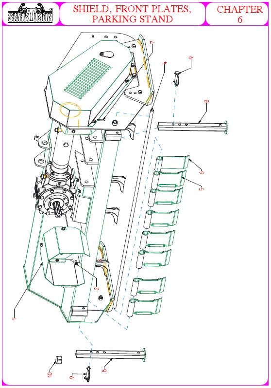
6 2.2. INTENDED USE The FLAIL MULCHER is designed specifically for cutting grass and for shredding fibrous wood stalks, corn and branches up to a diameter of 8 cm (depends on the type of blade fitted). The Flail Mulchers are designed to be mounted on tractors equipped with hydraulic lift and universal three point hitch that can support the implement weight, and driven by the power of the tractor through the PTO Shaft. The tractors used to operate the FLAIL MULCHER must have the following requirements: Hitch Category: PTO: Horsepower: 3-point hitch, I/II Category standard 540 RPM, 6-spline, 1 3/8 Z HP DANGER Any use of the implement other than the intended use is non-intended use, and is to be considered as unauthorized and dangerous. The manufacturer assumes no liability for damage resulting from nonintended use MAIN PARTS DESCRIPTION 1. Flail Mulcher body 10. Rear Rakes 2. Lower linkage point 11. Shredding Chamber 3. Lower linkage pin 12. Roller 4. Top link pin 13. Implement stand 5. Top linkage point 14. Side skid 6. Input shaft cover 15. PTO shaft 7. Input shaft 16. PTO shaft support 8. Gearbox (built in free wheel) 17. Rear Support Stay 9. Belt Cover 18. Hydraulic hoses NOTE To make the illustrations more clear, some images in this manual may picture implements with some safety guards removed. NEVER use a implement without all safety guards correctly fitted. 6


 2.5.")
7 2.4. CONFIGURATIONS The FLAIL MULCHER can be purchased in different configurations. The standard configuration can be changed applying one or more optional parts, listed below: STANDARD CONFIGURATION Mobile arc with hydraulic cylinder Rear roller Standard rear cover Y blades or hammers OPTIONAL Mechanical shifting device (instead of hydraulic cylinder) Rear cover with rakes (instead of standard rear cover) 2.5. TECHNICAL SPECIFICATIONS Technical specification of all models is as per the table on page 8. 7
8 MODEL SPECIFICATION Working width Recommended tractor HP 3-point hitch type Number of blades Number of hammers PTO input speed Rotor speed Side transmission Side shift (max) Rotor diameter Rotor swing diameter Approx Weight (PTO not included) Cm cm inches HP - N. N. rpm rpm - cm inches mm mm Kg x85x " Cat. I/II belts BX type SPECIFICATION x85x Cat. I/II belts BX type x85x Cat. I/II belts BX type x85x Cat. I/II belts BX type x85x Cat. I/II belts BX type x85x Cat. I/II belts BX type
9 3. SAFETY Proper use of the equipment, a strict observance of the safety messages listed below and application of all reasonable practices to avoid any risks, prevents accidents or injury, allows the implement to function better, increases longevity and minimizes failures. The manufacturer assumes no liability for any damage resulting from not applying the behavioral rules indicated into the manual GENERAL SAFETY INSTRUCTION DANGER The implement must be used only by authorized and well trained operators. The operator must have read and understood the instructions in this manual. It must make adequate preparation for the proper use of the implement and should hold a driving license. In case of doubt about the use of the implement and/or the interpretation of this manual, the operator must contact the Manufacturer or the Dealer. The manual must always remain with the implement. In case of loss or damage, request a new copy from the Manufacturer or your Dealer. Follow strictly the rules prescribed by the safety decals applied to the implement. Be sure that all safety decals are legible. If decals are worn, they must be replaced with others obtained from the Manufacturer, and placed in the position indicated by this manual. DANGER Before using the implement, make sure that all safety devices are installed and in good working conditions. In case of damages to shields or covers, replace them immediately. DANGER Is absolutely forbidden to remove or alter safety devices. DANGER Before starting, and during operation of the Flail Mulcher, make sure there are no people or animals in the operation area: the implement can project material from the back, with risks of serious injury or death. DANGER Pay maximum attention to avoid any accidental contact with rotating parts of the implement. DANGER During operation, adjustment, maintenance, repairing or transportation of the implement, the operator must always wear appropriate Personal Protective Equipment (PPE). 9
10 DANGER Do not operate the implement while wearing loose fitting clothing that may become entangled in the moving parts of the implement. DANGER Do not operate the implement when tired or unwell or under the influence of alcohol or drugs. CAUTION If the use of the implement is required at night or in conditions of reduced visibility, use the lighting system of the tractor and possibly an auxiliary lighting system EQUIPMENT SAFETY INSTRUCTION Use the Flail Mulcher for its intended purpose only. Improper use can damage the Flail Mulcher and cause serious injury to persons, animals, or death. DANGER The implement should be used by a single operator driving the tractor. Any unauthorized modification of the implement may cause problems in safety and relieves the Manufacturer of any liability for damages or injuries that may result to operators, third parties and objects. Before using the implement, familiarize yourself with its controls and its working capacity. Do not leave the Flail Mulcher unattended with tractor engine running. Keep the implement clean from debris and foreign objects which may damage functioning or cause injury. Do not use the implement if the category of the connecting pins of the Flail Mulcher does not match that of the tractor hitch system. Do not use the implement with missing bolts, screws, pins or safety pins, safety guards etc. Never use the implement to transport or lift people, animals or objects. 10
11 Make certain, by adding front ballast that at least 20% of the total weight (tractor, implement and ballast) is on the front axle of the tractor, to ensure stability. Before engaging the tractor PTO, make sure the tractor PTO speed is set as required for the Flail Mulcher (540 rpm). Do not use any other PTO speed other than the speed it has been designed. DANGER Do not operate the Flail Mulcher if the PTO shaft is damaged. A damaged PTO shaft can cause serious injury or death. Remove the PTO shaft and repair or replace before continuing operations. With Flail Mulcher disconnected from tractor, rest the PTO Shaft on the provided support of the Flail Mulcher OPERATING SAFETY INSTRUCTION Before using the implement, be sure to have cleared the operating area from obstacles (stones, branches, debris, etc...). Mark all the obstacles that cannot be removed (e.g. use flags or other suitable marker). DANGER Never engage the tractor PTO in the presence of people close to the PTO shaft. Body parts, hair or clothing can get caught in rotating parts, causing serious injury or death. DANGER Before engaging the PTO and during all operations, make sure that no person or animal is in immediate area of action of the implement. Never use the Flail Mulcher if people are in the operating area. DANGER It s absolutely forbidden to stand near the Flail Mulcher with moving parts. The operator must operate implement lifting/lowering only from the driving seat of the tractor. Do not per- form lifting maneuvers on the side or behind the tractor. Before making changes in direction, turns or going in reverse, slightly lift the Flail Mulcher off the ground. Disengage the PTO shaft before lifting the Mulcher for transport or in any situation that requires the Mulcher to be lifted well off the ground. 11
12 DANGER On steep slopes the angle can cause instability of the tractor with a risk of serious injury or death hazard. Consult the manual for the tractor to determine the maximum slope that the tractor is able to deal with. Always operate up and down (NEVER across) a steep slope. DANGER Always disengage the PTO before raising the Flail Mulcher, and never engage the PTO with the Flail Mulcher in the raised position. The implement might throw objects at high speed, causing serious injury or death. Never leave the driver s seat when the tractor is turned on. Before leaving the tractor, lower the Flail Mulcher to the ground, disengage the PTO, insert the parking brake, stop engine and remove the key from the ignition. DANGER Safety guards and covers on the tractor, implement and the PTO shaft must be properly installed and in good condition, to avoid risk of entanglement with serious injury or death. Stop all operations until all safety guards/covers are replaced. DANGER Before engaging the PTO of the tractor, always make sure that the PTO Shaft is locked in the angular groove of the input/output shaft and the spring pins are back to their original position. Be sure to check both to tractor output side and the Flail Mulcher side. Stop operating immediately if blades strike a foreign object. Repair all damage and make certain rotor and blades are in good condition before resuming operation. Always disengage the tractor PTO when the PTO Shaft looks like it will exceed an angle of 10 degrees. An excessive angle with the PTO Shaft rotating can break the PTO Shaft and cause flying projectiles. CAUTION Prolonged use of the Flail Mulcher can cause the gearbox to become hot. Do not touch the gearbox during use and immediately after, it could be extremely hot and cause severe burn. All adjustment operations on the Flail Mulcher must be performed by qualified and trained operators, with the tractor engine off, the PTO disengaged, the Flail Mulcher lowered to the ground or on support stands, the ignition off and the parking brake set. 12
13 3.4. TRANSPORTING SAFETY INSTRUCTION Before transporting the implement, determine the stopping characteristics of the tractor and implement. Transport only at speeds where you can maintain control of the equipment. When driving on roads, the implement must be in transport position adequately raised from the road surface, with tractor lower linkage arms locked so that the Flail Mulcher cannot be lowered accidentally. DANGER The implement may be wider than the tractor. Pay attention during transporting to persons, animals or obstacles exposed. When turning, use extreme care and reduce tractor speed. Do not operate the tractor with weak or faulty brakes or worn tires. CAUTION Always use tractor lighting system and auxiliary lighting system for an adequate warning to operators of other vehicles, especially when transporting at night or in conditions of reduced visibility. CAUTION In case is required the lifting of the implement, make sure that the lifting device chosen is suitable to perform the operation safely, and use only the lifting points prescribed on Flail Mulcher MAINTENANCE SAFETY INSTRUCTION All maintenance and repairing operations must be performed by qualified and trained operators, with the tractor engine off, the PTO disengaged, the Flail Mulcher lowered to the ground or on support stands, the ignition off and the parking brake set. Perform repairs and replacements necessary to the implement using only original spare parts provided by the manufacturer or your Dealer. DANGER Perform maintenance operations wearing appropriate Personal Protective Equipment (protective eye glasses, hard hat, hearing protection, safety shoes, overall and work gloves, filter mask). 13
14 CAUTION Before carrying out maintenance, make sure all parts have come to a stop and have cooled (gear box). Do not perform repairs that you are not familiar with. Always follow the manual instructions and in case of doubt contact the Manufacturer or your Dealer. DANGER Do not swallow fuels or lubricants. In case of accidental contact with eyes, rinse well with water and consult a doctor. 3.6 STORAGE SAFETY INSTRUCTIONS Never leave the tractor unattended with the Mulcher in lifted position. Accidental operation of lifting lever or a hydraulic failure may cause sudden drop of unit with injury or death by crushing. DANGER Following operation, or before unhooking the Mulcher, stop the tractor, set the brakes, disengage the PTO, lower the attached Mulcher to the ground, shut off the engine, remove the ignition key and wait for all moving parts to stop. DANGER Make sure all parked implements are on a hard, level surface and engage all safety devices. CAUTION Place support blocks under Mulcher as needed to prevent unit from tipping over onto a child and/or an adult. A Mulcher that tips over can result in injury or death. CAUTION Store the unit in an area away from human activity. 3.7 SAFETY DECALS The safety decals applied to the implement give fundamental information for using the implement safely. Make sure safety decals are in good conditions. If decals are worn, they must be replaced with others obtained from the manufacturer and placed in the position indicated by this manual. Make sure the safety decals are legible. If necessary, wipe them by a cloth, with soap and water. 14


15 SAFETY DECALS POSITION AND DESCRIPTION 1 Disengage the PTO, turn off the tractor engine, remove the key and ensure that all rotating parts have stopped before approaching the implement. Read the operator s manual before performing any maintenance operation. Thrown or flying objects hazard 15


16 2 Safety Wear 3 Crushing hazards & Thrown or Flying objects hazards. 4 Operate only with 540 rpm PTO. 5 Rotating Gears 6 Oil filling point 7 Lifting point 8 Grease filling point 9 Hand Hazard 16

17 4. SET UP The Flail Mulcher is delivered equipped with a PTO Shaft and related operating manual. When the implement is delivered, check that there is no damage to the Flail Mulcher or PTO Shaft. In case of damage or missing parts immediately notify the Manufacturer or your Dealer. Because of its size, the implement may require some be assembly. In this case, the assembly of such parts is the responsibility of the dealer and must be performed carefully with reference to the tables (spare parts and torque) in this manual. For proper tightening torques of bolts and screws, refer to the table in this manual CONNECTING TO THE TRACTOR The FLAIL MULCHER is designed to be mounted on tractors equipped with 3-point Hitch Category I (ISO 730 standard). To connect the Flail Mulcher to the tractor the operator must do the following: reverse the tractor up to the implement and align the rear lower linkage arms to lower linkage points of the Flail Mulcher then stop. (see picture below); set the tractor s parking brake, stop engine, remove the ignition key and get off the tractor; connect the lower linkage arms of the tractor to the lower linkage points of the Flail Mulcher and secure with pin and clip. Connect the top link to the top linkage point and secure with pins and clips; Fit PTO Shaft. Raise the Flail Mulcher so the PTO shaft is parallel to the ground. Now adjust the top link to the deck of the Flail Mulcher is parallel to the ground looking front to back. This will limit the forces that that the PTO shaft can transfer to your Mulcher. Next, adjust the lower linkage arms of the tractor to ensure the Mulcher is level left to right (looking from the back). May sure to lock the lower linkage arms once you have the Mulcher level and straight. If not, the moment could compromise the stability of tractor and implement; Raise support stand to its highest point and secure with pin and clip. Before connect the Flail Mulcher to the tractor, make sure that tractor and Flail Mulcher are on a flat, stable and dry surface 17


18 4.2. PTO SHAFT INSTALLATION Before installing the PTO shaft, the operator must read the manuals of PTO shaft and tractor, checking in particular that rpm and direction of rotation of the tractor PTO match those of the implement. If the direction of rotation of the PTO tractor does not match that of the implement contact your dealer. To connect the PTO shaft to the tractor and implement, the operator must: park tractor and implement on a flat surface, with parking brake set, engine off, and ignition key removed; check that safety devices on the implement PTO shaft and tractor are in good condition, otherwise provide for their replacement; position the PTO shaft between tractor and implement. NT you may need to remove the Input Shaft Cover to fit the PTO shaft. If you do, always remember to replace this cover: insert the PTO shaft yoke on the tractor s PTO output shaft, then ensure its locking into the angular groove; insert the PTO shaft yoke on the Implement s input shaft, then ensure its locking into the angular groove NT if the PTO shaft has chains to stop the covers spinning, hook one to the tractor and one to the implement. PTO SHAFT LENGTH CHECK Before operating the implement ensure that the size of PTO shaft is adequate. The PTO shaft supplied with the implement comes in a standard length. Therefore it may need to be shortened depending on you tractor and implement. The length of the PTO shaft must be such that it: avoid bottoming out of the transmission tubes, when the PTO shaft is in compressed position, when Mulcher is raised up off the ground; ensure there is sufficient overlapping of the transmission tubes, enough to transmit the torque required, when the PTO shaft is in max extension, with the Mulcher at its lowest position on the ground. When the PTO shaft is at its maximum operational extension, there must be an overlap between the tubes profiles of at least 15 cm (see below). When the PTO shaft is at its minimum length (max compressed position), there must be at least a 2 cm of distance between the ends of each transmission tube and the yokes side. A PTO shaft that is too long may cause structural damages to the tractor and implement. If the PTO shaft is too long, it may be adapted by removing it and shortening the tubes according to the instructions provided by the manufacturer in its use and maintenance manual. A PTO shaft that is too short can cause disengage of the tubes during operation, with severe hazard for the operator and structural damage to the tractor and implement. If the PTO shaft is too short, it must be replaced with a longer one. In this case contact the manufacturer or your dealer. 18
19 IMPORTANT before operating the implement the first time, make sure that the PTO shaft is lubricated in accordance with how indicated in the instruction booklet; always engage the tractor PTO at low rpm to minimize the effect of the peak torque on the PTO Shaft and the implement 4.3. TRACTOR-FLAIL MULCHER STABILITY The weight of the implement modifies the stability of the system tractor-flail Mulcher, resulting in loss of steering control and braking. The front axle of the tractor should always loaded with at least 20% of the overall weight of the system tractor-flail Mulcher. CAUTION Check the lifting capacity and stability of the tractor making sure the following relations are complied with (see table below for definitions): M x (S1+S2) 0.2 x T x i + Z x (d+i) M 0.3T If this not occurs, apply the front ballast required. To determine the appropriate characteristics of the ballast, refer to the manual of the tractor. Z 0.2 T T M d i s1 s2 i = Tractor wheelbase (cm) d = Distance between front axle and ballast center of mass (cm) T = Weight of tractor + operator (75 kg) Z = Ballast weight (kg) M = Implement weight (kg) s1 = Distance between rear axle and lower hitch points (cm) s2 = Distance between lower hitch points and implement center of mass = 61 cm 19
20 5. OPERATING Before operate the Flail Mulcher, make sure you have read and understood the operating manuals of the Flail Mulcher, tractor and PTO shaft, and followed what is described in the section Set Up. DANGER During operation, adjustment, maintenance, repairing or transportation of the implement, the operator must always wear appropriate Personal Protective Equipment (PPE). Before starting work, ensure that all implement guards are in good conditions and fully functional. During operation, the implement can throw material from the back: prevent people and animals to approach the operational area START-UP Before conducting the above inspections and service, make sure the tractor engine is off, all rotation parts are completely stopped and the tractor is in park with the parking brake engaged. Make sure the implement is resting on the ground or securely blocked up and the tractor lifting hydraulics locked. Before the start up and before each use, perform the following pre-operation inspections and service of the implement: check that the implement is not damaged and all mechanical parts are in good condition. Repair and/or replace any damaged parts; check that the implement has all the required pins, clips and safety guards fitted. Replace any damaged guards, covers, safety decals, etc. before operating; verify that the PTO Shaft is properly installed (see section: Connection of the drive shaft); verify that the PTO Shaft is the correct length for the tractor you are using. check the presence of lubricant in all greasing points of the implement and PTO Shaft (see sections: Maintenance / PTO Shaft and Maintenance / Support rotor); check for oil leaks from the gearbox. Identify the cause and repair and/or replace the damaged components before commencing operations; check the oil level in the gearbox is correct (see section maintenance); check that blades are not excessively worn and the relating hardware to secure them is correctly tightened (see section Maintenance); check that all hardware is properly tightened. Refer to the tightening table in the manual for proper torque values; check that all safety decals are in good condition and legible. Replace any damaged decals; check that rotor is spinning freely and there is no material wrapped around the rotor Before the start up and before each use, make sure you carry out a visual inspection of the operating area identifying that: the area is clear of foreign objects (rocks, branches or debris). foreign object have been remove or that immoveable obstacles have been marked with flags or other suitable visible markers; there are no people or animals in the operating area. Once all the checks above have been done, start the tractor and the Flail Mulcher as follows: start the tractor and engage the PTO at low rpm, making sure that the Flail Mulcher is NOT in the raised position but close to the ground, then increase the speed engine until to 540 rpm; lower the implement on the ground and simultaneously start driving the tractor at low speed. Subsequently increase the ground speed depending on ground conditions; if the environmental temperature is extremely cold, it s recommended to wait a few minutes with the PTO of the tractor at low rate before lowering the Flail Mulcher completely on the ground; 20
21 If the cutting height and/or the quality of the shredding are not as desired, correct them by adjusting the roller or the wheels (see sections Adjustments ) making sure you reduce engine speed, disengage PTO, set the parking brake, stop engine, remove key and lift the Flail Mulcher just off the ground BEFORE carry out the adjustment OPERATING INSTRUCTIONS During operations: always maintain tractor engine so rpm rate is as stated so that the Mulcher has sufficient power to carry out the job it has been designed to do; always keep a tractor speed adequate to working conditions (from 2 to 10 km/h approx.); where possible, drive in a manner that allows for long passes and minimizes turning; when working on slopes, always operate up and down the slope NEVER across. always perform severe charges in direction (i.e. forward to reverse, hard left/right) with PTO disengaged and/or the Flail Mulcher slightly lifted from the ground to avoid damage to the implement; periodically check for foreign objects that may have become wrapped around the rotor. Remove them immediately BUT ONLY after disengaging PTO, turning off tractor engine, and waiting for all moving parts to come to a complete stop; if you feel the rotor or blades strike a foreign object, stop operating IMMEDIATELY by reducing ground/engine speed and disengaging the PTO. Wait for all rotating parts to come to a complete stop, set the parking brake, stopped engine and removed the ignition key. Raise and block the implement and proceed to carry out a visual check of blades and moving parts. Repair any damages immediately and make sure rotor is in good condition before restarting operation; Visually inspect the area just cut and identify what could have caused the impact. Mark with flags. In heavy thick operation conditions it is important to monitor the temperature of the gearbox and ensure that it does not overheat. Typical problems that may occur operating the Flail Mulcher are described into Troubleshooting section, together with their solutions ADJUSTMENTS All adjustment operations must be performed with the tractor engine off, the PTO disengaged, the Flail Mulcher lowered to the ground or on rated support stands, the parking brake set and the ignition key off. CUTTING HEIGHT ADJUSTMENT The cutting height of the Flail Mulcher is determined by the vertical position of the rear roller, the rear wheels (if fitted in lieu of a roller) or the skid skids (if roller and/or wheels are not fitted). Raising the roller (or the wheels) will result in the blade/hammers becoming closer to the ground which will result in a reduced the cutting height. On the contrary, lowering the roller (or the wheels) will increase the distance the blades/hammers are from the ground increasing the cutting height. After a changing the cutting height make sure that the blades/hammers of the rotor are not touching the ground. Direct contact with the ground will result in the rapid wearing of the blades/hammers and excessive loads being placed on the Mulcher which will reduce its longevity. 21

22 If the Flail Mulcher is provided with a roller, adjust the cutting height as follows: Lift the Flail Mulcher onto rated safety stands. Turn off the tractor engine, disengage the PTO, set the parking brake and remove the key from the panel. Remove the bolts (1) that secure the roller supports to the frame on the both sides; Position the roller according to the height required; Replace and tighten the bolts (for the correct torque value refer to the torque table of the manual). Depending on the different roller positions, it is possible to set four different cutting heights of approx. 30mm, 60mm, 80mm and 105mm. Make sure that the roller supports are positioned at the same height on BOTH side with the Flail Mulcher resting on the ground. Check that the front of the implement is leveled (front to back and left to right). If necessary adjust the levels via the adjustable top link or the lower linkage arms of the tractor. 22
; remove the wheel/fork from")
23 If the Flail Mulcher is provided with depth wheels (see picture) adjust cutting height as follows: lift the Flail Mulcher onto rated support stands. Turn off the tractor engine, disengage the PTO, set the parking brake and remove the key from the panel; while supporting the weight of the wheel/fork, remove the clip (1); remove the wheel/fork from the bracket paying careful attention to the spacers (2) (required to determine the cutting height); insert one or more spacers onto the lower part of the shaft of the wheel fork. The number of the spacers placed on the lower part of the wheel fork shaft will increase the cutting height; insert the wheel fork into the bracket and place remaining spacers on top of the shaft; fix the wheel fork in place with the clip (1); repeat the same procedure to the opposite wheel, making sure the same number and sized spacers are as per the first wheel. Depending on the different position of the spacers on the shaft, it is possible achieve five (5) different cutting heights of approx. 70mm, 75mm, 90mm, 115mm and 145mm. Before commencing operations make sure that the depth wheels are positioned at the same height with the Flail Mulcher resting on the ground. That the front of the implement is leveled with the back and it is level left to right as well. If not, adjust using the tractors adjustable top link or lower linkage arms. 23
. The skids can be placed in 3 different positions.")

24 The position of the skids can be adjusted by: SKID ADJUSTMENT Loosening and removing the bolts (1) that clamp the skids to the side plates of the frame, Reposition the skids according to the needs, and Retightening the bolts (1). The skids can be placed in 3 different positions. HOWEVER, when there is a roller or depth wheels fitted to your Mulcher the skids are there to act as a secondary height stop protecting the Flail Mulcher from bottoming out and the rotor/side walls coming in direct contact with the ground. The skids should NEVER be position below that of the roller or depths wheels. If they are, the roller or depth wheels will not be functioning as they are design as a result of the skids acting as the primary height setting device lifting the Mulcher off the ground. RAKE ADJUSTMENT The function of the rear rakes is to hold cut material inside the Mulcher to obtain a fine finish. It is therefore recommend to set the rake height immediately after the cutting height. To set the rake height, follow the following procedure: remove the upper and lower cotter pins (1) from one of the rakes; push the rake downwards in order to retain more material inside the shredding chamber and obtain a more fine crushing. Vice-versa, pull the rake upwards to retain less material inside the shredding chamber and to obtain a more coarse crushing; insert the split pins (1) on the holes of the rake closest to rear bar; repeat the procedures adjusting all other rakes to the same height of the first one. 24

25 SIDE SHIFTING ADJUSTMENT The Flail Mulchers can be purchased with either mechanical or hydraulically shifting tower. In case of a mechanical shifting tower, the tower is bolted to the body. Adjust the position of the tower for a mechanical tower as follows: Raise implement slightly off the ground, turn off the tractor engine, disengage the PTO, set the parking brake and remove the key from the ignition; Unscrew and remove the bolt (1); Manually move the body of the Flail Mulcher by pushing it from one side, until the desired offset is reached and the holes are in alignment in the mechanical jack; Reinsert the bolt removed earlier and tighten. In cases where the offset feature is controlled by a hydraulic cylinder, the adjustment is controlled from the tractor using the tractors hydraulics to activate the hydraulic cylinder attached to the Mulcher. NT The hydraulic hoses must be fitted correctly to a tractor with working hydraulics to adjust the offset. For more information on how to control the hydraulics of your tractor, please refer to the tractor manual. 25
 bolts (1)")
 pulleys and record the movement of the belts")
26 BELT TENSIONING ADJUSTMENT To check the correct belt tensioning of the side transmission, remove the safety cover of the belts by loosening the four (4) bolts (1) that secure it to the side wall of the Mulcher (see picture): Apply a force of about kg half way between the two (2) pulleys and record the movement of the belts (see picture): 26
: loosen the four nuts (1) under the gearbox that secure it to the body; loosen the two bolts (2)")
 tighten the screw (3). If the tension was too tight (belts has less than 10mm of movement) loosen the screw (3).")
27 If the deflection is about 10 mm, the tension is correct. If is more than 10mm then you will need to proceed with an adjustment as follows (see pictures below): loosen the four nuts (1) under the gearbox that secure it to the body; loosen the two bolts (2) fixing the extension tube to the side plate of the body; while holding the screw (3), loosen the lock nuts (4); Adjust the tension on the plate (5). If the tension was too low (belts had more than 10mm of movement) tighten the screw (3). If the tension was too tight (belts has less than 10mm of movement) loosen the screw (3). Once the correct belt tension has been achieved tighten the lock nuts (4). retighten the two bolts (2) fixing the extension tube to the side plate of the frame; adjust the gearbox so that the extension tube is perpendicular to the side plate of the Mulcher; retighten the four nuts (1) under the gearbox; reattached the belt cover as original fitted. 27
28 If the belts are worn or damaged and need to be replaced: remove the safety cover of the belts by loosening the four bolts that secure it to the frame; loosen the four nuts (1) under the gearbox which lock it to the frame; loosen the two bolts (2) fixing the extension tube to the side plate of the frame; loosen the lock nuts (4) and the tension nut (5) until the belts can be unseat from the grooves in the pulley. Always starting with the external belt (position (a)); reinsert the new belts in reverse order to the way the old belts were removed; adjust the belt tension according to the instructions above; retighten the two bolts (2) fixing the extension tube to the side plate of the frame; adjust the gearbox so that the extension tube is perpendicular to the side plate of the Mulcher; retighten the four nuts (1) under the gearbox; reattached the belt cover as original fitted STOPPING AND DISCONNECTION To stop the Flail Mulcher at the end of a working session: bring the tractor to a complete stop; place the transmission in park or neutral; reduce the engine speed then disengage the PTO; wait for stopping of all rotating parts; lower the implement to the ground; set the parking brake; shut down the engine and remove the key before exiting the tractor; do the cleaning and maintenance required to make the implement ready for later use (see section maintenance). 28
29 Never leave the tractor unattended with the implement raised. To disconnect the Flail Mulcher from the tractor (e.g. to make a change of implement): Park the tractor on a dry and level surface; Reduce the engine speed, then disengage PTO; Wait for stopping of all rotating parts; Adjust the support stand to the lowest position use the pin and clip; Lower the implement to the ground; Set the parking brake; Shut down the engine and remove the key before exiting the tractor; Disconnect the PTO Shaft from the tractor PTO and rest it on the provided support of the Flail Mulcher; Disconnect the top link and rear lifting arms of the tractor from the Flail Mulcher hitches; Check the Flail Mulcher stability. If needed, place additional safety blocks; Get on the tractor, start the engine and move away from the Flail Mulcher slowly; Make sure the Flail Mulcher remains stored in a protected area, to prevent that unauthorized personnel can approach it. Before a long term storage (e.g. at seasonal end), do cleaning and maintenance operations as specified in the MAINTENANCE and STORAGE sections of this manual TRANSPORTING To set the Flail Mulcher for transportation, perform the following steps: reduce tractor engine to idle, disengage, or make sure tractor PTO is disengaged and wait for moving parts to come to a complete stop; lift the Flail Mulcher until it is high enough to transport making sure the tubes of PTO Shaft do not contact the body of the Flail Mulcher and the Flail Mulcher cannot touch the tractor. NT The minimum gap should be 2 cm (see also section PTO Shaft installation); lock the tractors lower linkage arms so that the implement cannot lower during transport. When driving on public roads, follow strictly all local laws and traffic regulations. When driving on public roads, reduce your speed, be aware of traffic around you and proceed in such a way that complies with local laws ensuring faster moving vehicles may pass you safely. If commencing work, setup Mulcher as per the instruction in section 5.1. START-UP. At the end of the day shut down and store Mulcher as per instructions as per MAINTENANCE and STORAGE sections of this manual 6. MAINTENANCE Proper and regular maintenance ensures longevity and avoids failures which can be time consuming and costly. Periodic inspections and maintenance described in this section must be performed by the operator at all times as per the terms prescribed. Failure to comply with maintenance prescriptions can compromise the functioning and duration of the implement, and consequently void the warranty. The frequency of maintenance refers to average conditions and use. Service internal frequency must be increased based on use and operating conditions (frequent stops and starts, prolonged winter season etc.). Repairs, maintenance and modifications other than those mentioned in this paragraph should NOT be performed without consulting the Manufacturer or your Dealer. The manufacturer may, on a case by case basis, authorize repairs with strict instructions. Wrong or inappropriate repairs or maintenance may result in equipment damage and increase the risks to the operator. 29

30 For safety reasons, all maintenance operations must be performed with tractor PTO disengaged, Flail Mulcher stopped and completely lowered to the ground or onto rated support blocks, parking brake set, tractor engine shut off, and ignition key removed. IMPORTANT Respect the environment. Store or dispose of unused chemicals and fluids as specified by the manufacturer BLADE REPLACEMENT Frequently check the condition and wear of the blade/hammer on the rotor through visual inspection. The wear will vary depending on the type of material being cut, abrasiveness of the soil, moisture, etc. Operators should notice an increase of power absorption during operations when the blades or hammers are worn. The quality of the material being cut will reduce as the blades/hammers wear. Before changing blades/hammers: Reduce tractor engine to idle, set the parking brake, disengage tractor PTO, and wait for all moving parts to come to a complete stop; place the implement slightly lifted from the ground on rated safety blocks or mechanical stands; lock the control lever of the hydraulic lift of the tractor; turn off the tractor and remove the key from ignition. To replace blades/hammers: remove the bolt that locks the two (2) blades (will look like a Y ) or the hammer in the holders on the rotor. NT - For the Y blades, two bushing are placed on the bolt to fill the gap between the blades and the holders of the rotor; place the new blade(s) or hammer in the place of the worn parts, refit bolt and tighten. Make sure any washers are replaced and tension is as per the torque values shown in Torque Table in this manual. NT If fitting hammers be sure to install the cutting edge facing the direction of rotation. repeat this process for all the blade/hammer. IMPORTANT Remove and install one blade/hammer at a time to ensure blades/hammers are correctly oriented when installed. Replace worn blades only with original parts. When the blades/hammers are worn out it is necessary to replace the full set of blade/hammer. Replacing only some of the blade/hammer is certainly cause of the rotor unbalance, implement vibrations and can compromise the reliability of the Flail Mulcher and generates risks to the operator. CAUTION Worn blades and hammers may be very sharp! 30
.")
31 6.2. GEARBOX LUBRICATION Lubrificant: AGIP ROTRA MP SAE 85W/140 oil gear or equivalent CAUTION Before touching the gearbox, check that it is cool. Gearboxes can become very hot during operation. Check the oil level every 50 hours, making sure the level is aligned with the level plug (1). To perform the check, it is necessary to remove the screws (2) holding the Input Shaft Cover on the gearbox, which prevents access to the plug. If the oil level is below the line of the level plug, it will require a top up to restore the correct level. The oil change must be performed: after the first 50 working hours; each 500 working hours. To make the oil change: unscrew the level plug (1); place a tank under the oil drain plugs (3) and (4); unscrew the oil drain plugs (3) and (4) and drain oil completely into the tank; retighten the drain plug (4); unscrew the oil filling plug (5) on the top of gearbox; fill up with oil till the level reach the hole of the level plug (1); retighten level plug (1) and the filling plug (5); replace the safety cover retightening the screws (2); dispose the discharged oil into containers for used oil. IMPORTANT Frequently check possible oil leaks from the Flail Mulcher through visual inspection, and in case of leakage provide immediately proper maintenance. Avoid oil leaks on the ground when restoring oil level or making oil change. 31
 and inject grease through the nipple (2); inject grease through the nipple (3). IMPORTANT Make sure to clean the grease nipple before using the grease gun.")
 Frequency: each 20 working hours To perform lubrication, inject grease into the")
32 6.3. ROTOR BEARINGS LUBRICATION Lubricant: AGIP GREASE MU EP 2 lithium-type grease (or equivalent) Frequency: each 20 working hours To perform lubrication (see pictures): turn the cover (1) and inject grease through the nipple (2); inject grease through the nipple (3). IMPORTANT Make sure to clean the grease nipple before using the grease gun. Do not let excess grease collect on or around parts, particularly when operating in sandy areas ROLLER BEARINGS LUBRICATION Lubricant: AGIP GREASE MU EP 2 lithium-type grease (or equivalent) Frequency: each 20 working hours To perform lubrication, inject grease into the nipples (1) and (2), located on the upper part of the roller bearing supports (see pictures). 32
, located on the")
 Frequency:")
, located on the lower part of the shifting tube of the hitch; inject")
33 6.5. WHEELS BRACKETS LUBRICATION Lubricant: AGIP GREASE MU EP 2 lithium-type grease (or equivalent) Frequency: each 20 working hours To perform lubrication, inject grease into the nipple (1), located on the inner part of the wheel bracket (see picture) POINT HITCH LUBRICATION Lubricant: AGIP GREASE MU EP 2 lithium-type grease (or equivalent) Frequency: each 20 working hours To perform lubrication of the shifting parts of the 3-point hitch (see pictures): inject grease into the nipples (2), located on the lower part of the shifting tube of the hitch; inject grease into the nipples (3), located on the rod-tie of the hitch. 33
34 6.7. DRIVE BELTS REPLACEMENT Frequently check the wear of the belts, and if one or more of these appears worn replace the full set. To replace the drive belts, refer to the section Belts tensioning adjustment PTO SHAFT MAINTENANCE Lubricant: AGIP GREASE MU EP 2 lithium-type grease (or equivalent) Frequency: each 20 working hours Grease crosses, sliding parts of protective shielding and PTO Shaft transmission tubes. IMPORTANT For details about maintenance and lubrication of the PTO Shaft, refer to the user manual of the PTO Shaft manufacturer. NOTE For the PTO Shaft service parts, refer to the user manual of the PTO Shaft Manufacturer. 7. STORAGE Before leaving the Mulcher unused for long periods of time, it s necessary to perform following tasks to preserve the appearance and functionality of the implement, and to make easier the restart at later use: park the Flail Mulcher on a flat surface, in a place dry and protected from exposition to the elements, Optimum storage temperature is between 0-50 C (see section Stopping and disconnection); thoroughly clean the implement, removing any material from the rotor which will help prevent rust; inspect carefully the implement, checking for worn and/or damaged parts. Perform repairs immediately in case of damage to painted surfaces, restoring the surface with touchup paint to prevent rust; make sure the safety decals are in their original positions, intact and legible. Replace if damaged; lubricate all grease points and restore the oil levels as indicated in the Maintenance section. In extreme environments, use oil as a protective coat to the exposed mechanical components to protect them against rust. 8. SCRAPPING In a situation where the implement is beyond repair and going to be scrapped, the implement must be disposed in appropriate and authorized sites, according to local legislation. Before scrapping, separate plastic parts from rubber parts, aluminum, steel, etc. Recover and dispose any exhausted oils to authorized centers for oil collecting. 34
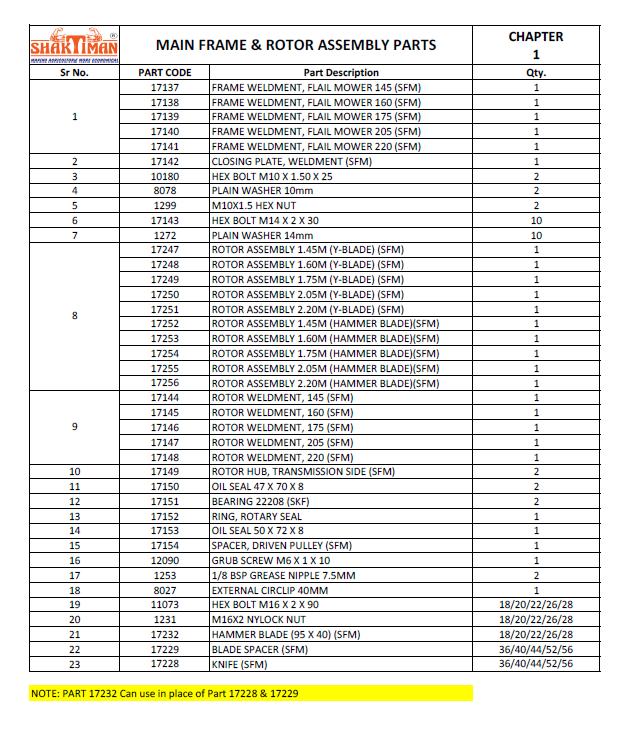
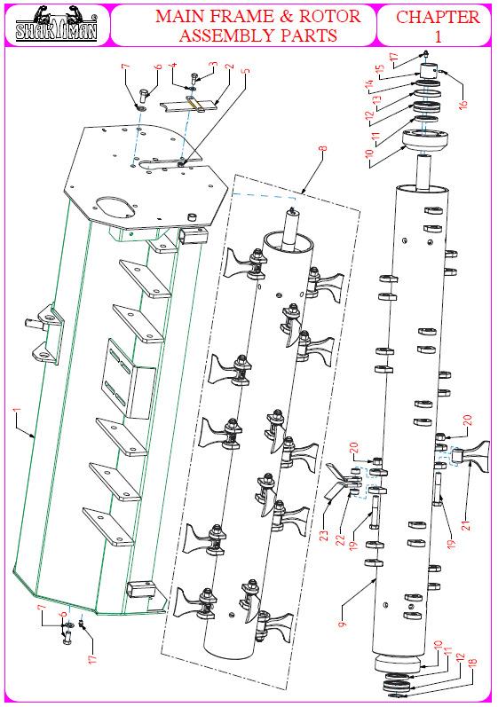
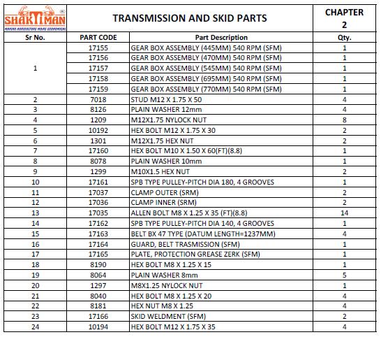
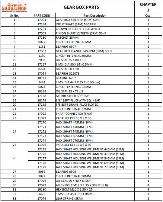
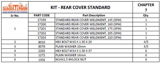
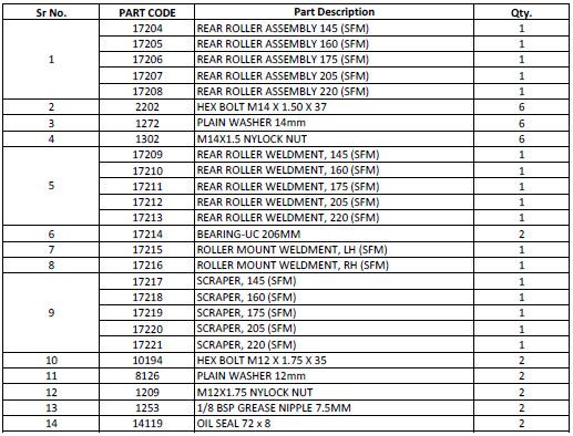
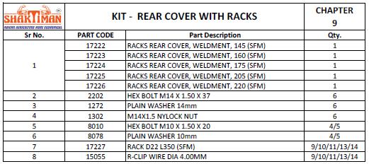
35 9. TROUBLESHOOTING PROBLEM POSSIBLE CAUSE POSSIBLE SOLUTION Oil leaking from gearbox/ transmission case Cut not uniform Gearbox overheating Blades/hammers wear frequently Flail Mulcher noise and vibration noticeable and Constant 10. TORQUE VALUES TABLE Gearbox overfilled Loose filling/drain/level plug Damaged breather plug Damaged seals Worn blades/hammers Roller/wheels set in wrong way Debris wrapped on rotor Low oil level Materiale di diffi cile Hard trash Cutting height too low Unbalanced roller Worn bearings Blades/hammers worn, damaged or missing Drain to proper level Replace breather plug Tighten filling/drain/level plug Replace seals Replace blades/hammers Set the roller/wheels correctly Reduce the ground speed Clean the shredding room Add oil Reduce the ground speed Check the soil in advance Increase the cutting height Balance the roller in authorized shop Replace bearings Replace blades/hammers Check frequently Flail Mulcher hardware to make sure that screws and bolts are tightened according to torque values listed in following table: 11. SPARE PARTS 8.8 GRADE 10.9 GRADE BOLT SIZE N N (METRIC) m m M 1 1 M 2 3 M 5 7 M 9 1 M 1 2 M 2 3 M 3 4 M 4 6 All replacement of parts must be original spare parts obtained from the Manufacturer or your Dealer. This section contains the information needed to identify the parts of FLAIL MULCHER that may be ordered to Manufacturer. When request spare parts to Manufacturer, always give following indications: Type of Implement Serial number Description and part number of the part required Quantity required NOTE For identification of p/numbers and description of safety decals refer to the Section Safety decals. For identification of p/numbers and description of PTO Shaft parts, refer to the manual of the PTO Shaft Manufacturer. The Manufacturer reserves the right to substitute a required part with an equivalent part, if applicable. 35
36 36
37 37
38 2. 38
39 39
40 40
41 41
42 42
43 43
44 44
45 45
46 46
47 47
48 WARRANTY Tirth Agro Technology Pvt. Ltd. offer the following warranty to the purchaser of COSMO BULLY FLAIL MULCHER mentioned herein above subject to the conditions set out herein after provided the COSMO BULLY FLAIL MULCHER shall be in the possession of and used by such purchaser as from the date of delivery. Tirth Agro Technology Pvt. Ltd. warrants its products for a period of twevle (12) months against defective parts. This warranty shall not apply to implements or parts that have been subjected to negligence, of accident, or that have been altered or repaired or used with non-genuine parts. CONDITIONS If you wish to make a warranty claim you must first contact the supplier of your goods to begin the claim process. The following are the warranty terms and conditions for new goods sold in Australia by Farm Implements P/L in conjunction with the manufacture Tirth Agro Technology Pvt. Ltd ( We, Our or Us ), both of 16 Cahill Street, Dandenong, Victoria, Australia, To the extent that any goods or services supplied by Us are supplied to a consumer as defined in the Australian Consumer Law, We will comply with any applicable consumer guarantees and the following statement will apply: Our goods come with guarantees that cannot be excluded under the Australian Consumer Law. You are entitled to a replacement or refund for a major failure and for compensation for any other reasonably foreseeable loss or damage. You are also entitled to have the goods repaired or replaced if the goods fail to be of acceptable quality and the failure does not amount to a major failure. 2. Australian Consumer Law means Schedule 2 of the Competition and Consumer Act 2010 (Cth). 3. The warranties provided in this document are in addition to any other rights or remedies available to you under the law, and do not limit the consumer guarantees for consumers under the Australian Consumer Law. 4. Goods presented for repair may be replaced by refurbished goods of the same type rather than being repaired. Refurbished parts may be used to repair the goods. 5. Any warranty claim that is the result of operator abuse, neglect or unauthorized modifications being made to the good will not be considered valid, subject to the Australian Consumer Laws. The warranty does not cover costs of claiming under this warranty; depreciation, damage, malfunction or failure caused by normal wear and tear; lack of reasonable maintenance or improper servicing; failure to follow operating instructions; misuse or lack of proper protection during storage. The expected normal working conditions and maintenance requirements are outlined in the relevant operator s manual. 6. All new Implements are provided with a 12 month comprehensive warranty from the date of invoice against faulty workmanship or materials, under normal working conditions and service, as outlined in the relevant operational manual for the particular good. Your warranty for those goods will be considered void if any damage to the implement is caused by operator abuse, neglect, or if any unauthorized modifications have been made. 7. If you wish to make a warranty claim, you must immediately report the defect to the supplier within the warranty or consumer guarantee claim period, including a written statement of your claim, along with photos of the current condition of the goods by mail (or if possible, ) to the address of the place from which you purchased the good. You will be required to present valid proof of purchase, and at your expense promptly provide the goods to the supplier immediately after notification of a service issue. 8. Please note that We require an assessment of the condition of the goods to be conducted by either the supplier, Us or the manufacturer, as well as obtaining a history of use of the good, before We can determine whether a consumer guarantee or manufacturer s warranty is applicable. We are not responsible for any transportation cost incurred in the repair or replacement of parts not covered by the warranty. 9. To the maximum extent permitted by law, and except in circumstances where the consumer guarantee provisions under the Australian Consumer Law apply and are inconsistent with the following, Our liability for the supply of the goods is limited, at Our discretion, to 1) replacement of the goods or the supply of equivalent goods; 2) repair of the goods; 3) payment of the cost of replacing the goods or acquiring equivalent goods; or 4) payment of the cost of having the goods repaired. 48
49 10. You acknowledge that use of the goods is inherently dangerous and agree that to the maximum extent permitted by law, We are not liable in any event for consequential loss, damage or injury, including loss of crops, loss of profits, or personal injury or death howsoever caused. 11. Farm Implements Dealers have no authority to make any representation, promise or admission on behalf of Us or to modify the terms or limitations of these Warranty Conditions in any way. Nothing in these Warranty Conditions constitutes a partnership between Us and any Farm Implements Dealer, or constitutes any Authorised Dealer as an agent or employee of Ours for any purpose at all. Our Dealers have no authority or power to bind Us, to contract in the name of Farm Implements P/L or to create a liability against Us in any way or for any purpose at all, including but not limited to representations regarding performance or fitness for any purpose of the goods. If you have specific queries regarding the warranties or consumer guarantees provided by Farm Implements P/L in conjunction with the manufacture Tirth Agro Technology Pvt. Ltd please send details of your claim to Our attention at 16 Cahill Street, Dandenong, Victoria, Australia, 3175, or via at kanga@farmimplements.com.au or phone THIS CONTRACT WILL BE INEFFECTIVE AND INOPERATIVE IF: i. The COSMO BULLY FLAIL MULCHER has not been delivered, assembled, started and put into operation by the company or it s Authorized Representative. ii. The warranty card has not been returned within 30 days of date of purchase. iii. The COSMO BULLY FLAIL MULCHER parts thereof is subjected to neglect, fire, flood or other acts of God or if in the company s opinion any damage has caused to the COSMO BULLY FLAIL MULCHER in transportation. iv. The original numbers are removed, obliterated or altered from the unit. v. Any attempt is made to have the repairs executed by a person or persons, other than the company or its authorized representative. vi. Any defect is not informed immediately to the company or its authorized representative, any alteration in warranty card is made. vii. Any change in the location of the COSMO BULLY FLAIL MULCHER or in its ownership during the warranty period must be intimated in writing to the company or its Authorized Representative ten days before the change. Failure to do so will absolve the company from the obligation under this warranty. viii. Damage to the COSMO BULLY FLAIL MULCHER or any part thereof caused, during shifting or transportation is not covered by this warranty. ix. This warranty is given in lieu of all other guarantees and condition expressed or implied by law or by any person purporting to act on behalf of the COMPANY and excludes every condition, warranty or guarantee not herein expressly set out. NT Parts/materials that are not covered by the warranty are as follows: Blade Universal Joint Cross Paint Bearings Rubber components Gaskets Hardware/fasteners (nuts, bolts, chains, etc.). WHEN THE WARRANTY BECOMES VOID Besides the cases specified in the supply agreement, the warranty shall in any case become void: Should there have been a maneuvering error, use of an inadequate safety bolt on the cardan shaft torque limiter or when the cardan shaft clutch has been damaged through improper maintenance. When the implement has been used beyond the specified power limit as stated in the technical data chart. When following repairs made by the customer without authorization from the manufacturer or the instillation of spurious spare parts, the machine is subjected to variations and the damage can be atributed to these variations. Whenever the user or anyone else on his behalf applies equipment to the machine that has not been expressly approved by the manufacturer. When the user failed to comply with the instructions in this manual book. 49
50 EC DECLARATION OF CONFORMITY In accordance with the EC Implementry Directive 2006/42/EC The company COSMO S.r.l. in conjunction with Tirth Agro Technology Pvt. Ltd. (An ISO 9001:2008 Certified Company) National Highway 27, Nr. Bharudi Toll Plaza, Gondal Road At.: Bhunava Ta. Gondal, Dist.: Rajkot. State: Gujarat- INDIA. hereby declares that the implement: Type: COSMO BULLY Flail Mulcher Model: SFM - Series satisfies the basic safety and health requirements established by European Directive 2006/42/EC. Harmonized standards used: EN ISO Safety of implementry - General principles for design - Risk assessment and risk reduction EN ISO Agricultural implementry - Safety - Part 1: General requirements EN ISO Agricultural implementry - Safety - Part 12: Rotary disc and drum Mulchers and flail Mulchers Other technical standard used: ISO Tractors, implementry for agriculture and forestry, powered lawn and garden equipment - Safety signs and hazard pictorials - General principles Ashwin Gohil / Hasmukh Gohil Chairman / Managing Director Rajkot, 10 October

51 Tirth Agro Technology Pvt. Ltd. (An ISO 9001:2008 Certified Company) National Highway 27, Nr. Bharudi Toll Plaza, Gondal Road At.: Bhunava Ta. Gondal, Dist.: Rajkot. State: Gujarat- INDIA.
ROTARY TILLERS Lowery Model SERIES LMC1.8(LM72)
") ROTARY TILLERS Lowery Model SERIES LMC1.8(LM72) OPERATOR'S AND PARTS MANUAL Lowery Manufacturing, Inc. 145 AL Hwy. 179 Boaz, AL 35957 855-646-9624 or 256-593-8842 www.lowerymanufacturing.com lmcsales@lowerymanufacturing.com
ROTARY TILLERS Lowery Model SERIES LMC1.8(LM72) OPERATOR'S AND PARTS MANUAL Lowery Manufacturing, Inc. 145 AL Hwy. 179 Boaz, AL 35957 855-646-9624 or 256-593-8842 www.lowerymanufacturing.com lmcsales@lowerymanufacturing.com
OPE R AT O R S MANU A L QUICK-HITCH ADAPTER. 5BP (Field conversion kit)
") OPE R AT O R S MANU A L 5BP006750 (Field conversion kit) Manual 5BP97378B Date 06/8/05 SAFETY Take note! This safety alert symbol found throughout this manual is used to call your attention to instructions
OPE R AT O R S MANU A L 5BP006750 (Field conversion kit) Manual 5BP97378B Date 06/8/05 SAFETY Take note! This safety alert symbol found throughout this manual is used to call your attention to instructions
BEFCO. Operator s Manual BABY HOP & HOP FERTILIZER SPREADERS ACCESSORIES SIDE ROW DISCHARGE. AA4-120 (fits models Hop 209 & 212) DEFLECTOR
 DEFLECTOR") BEFCO Operator s Manual BABY HOP & HOP FERTILIZER SPREADERS ACCESSORIES SIDE ROW DISCHARGE AA-0 (fits models Hop 09 & ) DEFLECTOR AA-0 (fits models Baby Hop 0 & 06) 009-95 (fits models Hop 0 & 06) 009-968
BEFCO Operator s Manual BABY HOP & HOP FERTILIZER SPREADERS ACCESSORIES SIDE ROW DISCHARGE AA-0 (fits models Hop 09 & ) DEFLECTOR AA-0 (fits models Baby Hop 0 & 06) 009-95 (fits models Hop 0 & 06) 009-968
Finishing Mower Estate 72
 Finishing Mower Estate 72 Owners/Operators Manual & Spare Parts List Issue Date: October 2011 1 Introduction Your FIELDMASTER Estate 72 Finishing Mower has been designed to do a range of work to your satisfaction.
Operator s ManualMOWERS
 Operator s ManualMOWERS ATTENTION Carefully read this manual before using the machine M48-S M48-A M60-S M60-A M72-S M72-A M84-S M84-A March 2009 page 1 page 2 Belco Resources Equipment PO Box 8164 Rocky
Post Hole Digger. Operation Manual MODEL
 Post Hole Digger MODEL 107798 Operation Manual This safety alert symbol identifies important safety messages in this manual. Failure to follow this important safety information may result in serious injury
Post Hole Diggers Compact Standard Heavy Duty
 Post Hole Diggers Compact Standard Heavy Duty MODEL 90 / MODEL 100 / MODEL 110 # 100623 # 100498 # 100624 Operation Manual This safety alert symbol identifies important safety messages in this manual.
BEFCO. Operator s Manual POST HOLE DIGGER ACCESSORIES DOWN FORCE KIT. PHD-002 (fits models MOLE 300 & 400) PHD-005 (fits model MOLE 200) HOOKUP STAND
 PHD-005 (fits model MOLE 200) HOOKUP STAND") BEFCO Operator s Manual POST HOLE DIGGER ACCESSORIES DOWN FORCE KIT PHD-00 (fits models MOLE 300 & 400) PHD-005 (fits model MOLE 00) HOOKUP STAND 009-985 (fits models MOLE 00, 00, 300 & 400) POSITIONING
BEFCO Operator s Manual POST HOLE DIGGER ACCESSORIES DOWN FORCE KIT PHD-00 (fits models MOLE 300 & 400) PHD-005 (fits model MOLE 00) HOOKUP STAND 009-985 (fits models MOLE 00, 00, 300 & 400) POSITIONING
OPERATORS MANUAL FOR KAFURTER ROTARY TOPPERS MODELS: TP110, TP140, TP160, TP170
 OPERATORS MANUAL FOR KAFURTER ROTARY TOPPERS MODELS: TP110, TP140, TP160, TP170 SAFETY WARNING: Do not use or operate this this manual and assembly instructions (where applicable) has been read and understood.
Mulcher Operators Manual
 Mulcher Operators Manual Skid Pro Attachments PO Box 982 Alexandria, MN 56308 October 2015 1 2 Contents 1. Introduction And Warranty... 4 1.1 Introduction... 4 1.2 Warranty... 4 2. Component Identification...
Berta Flail Mower Attachment. BCS Power Units
 Manufactured by Berta s.r.l. to fit BCS Power Units Operating Instructions Before commissioning the machine, read operating instructions and observe warning and safety instructions. PLEASE ALSO READ ORIGINAL
Operator's Manual. VC-60 & VC-60 Plus Harper Industries, Inc. 7/03 Part No
 Operator's Manual VC-60 & VC-60 Plus 2003 Harper Industries, Inc. 7/03 Part No. 970066 Thank you for purchasing a Harper/Goossen Verti-Cutter. As with all Harper/Goossen products, the Harper/Goossen Verti-Cutter
Trench Filler for Compact Utility Loaders
 Form No. 3353-608 Rev A Trench Filler for Compact Utility Loaders Model No. 22472 260000001 and Up Operator s Manual Register your product at www.toro.com Original Instructions (EN) Contents Page Introduction................................
TL SERIES ADJUSTABLE OFFSET TILLER
 R L S E S 995 OPERATION & PARTS MANUAL Please read these instructions carefully before using! Always grease all fittings and be sure to always check and fill with oil before operating! Retain this manual
LP1207 LP1208 LP1210 LAND PLANES LP12_5TL15788_06/10
 LP1207 LP1208 LP1210 O P E R A T O R ' S M A N U A L LAND PLANES LP12_5TL15788_06/10 TO THE DEALER: Assembly and proper installation of this product is the responsibility of the Frontier dealer. Read manual
WOOD CHIPPER WC1103 5PQ (8/02/12)
") O P E R A T O R ' S M A N U A L WOOD CHIPPER WC1103 5PQ990101 (8/02/12) To the Owner; Thank-You for choosing a quality product from Frontier Equipment. We strive to give you the best equipment and the
O P E R A T O R ' S M A N U A L WOOD CHIPPER WC1103 5PQ990101 (8/02/12) To the Owner; Thank-You for choosing a quality product from Frontier Equipment. We strive to give you the best equipment and the
AG PRODUCTS, LTD. YOU RE ALWAYS AHEAD... WITH A MODERN BEHIND.
 SUMMER 2016 BADGER DISC HARROW Operator s Manual 011-1156 011-1166 001-1501 001-1501-1 011-1167 001-1501-2 001-1501-3 011-1176 001-1501-4 011-1177 MODERN AG PRODUCTS, LTD. YOU RE ALWAYS AHEAD... WITH A
WARNING this attachments capacity changes depending on the Skid Steer Loader it is hooked up to. CAPACITY AT 24 LOAD CENTER
 SKID STEER FORKLIFT ATTACHMENT Any piece of equipment can be dangerous if not operated properly. YOU are responsible for the safe operation of this equipment. The operator must carefully read and follow
W & A 12 ROW TOP LEVELING STACKER LEVEL BANDER
 W & A 12 ROW TOP LEVELING STACKER LEVEL BANDER NO. 3640 OPERATOR S MANUAL TO THE OWNER: Congratulations on your purchase of a new W & A Top Leveling Stacker Level Bander. Your selection is an indication
RED23305 Owner s Manual
 RED23305 Owner s Manual 5 foot, 3-Point Mounted Snow Blower 270 West Park Avenue Huron, SD 57350 866-526-5682 Serial Number: Date of Purchase: Red Devil Snow Blower See Figure 1. 1. The Red Devil Snow
FERTILIZER SPREADERS MODEL PL180, PL400 & PL500
 FERTILIZER SPREADERS MODEL PL180, PL400 & PL500 SAFETY INSTRUCTIONS; OPERATING INSTRUCTIONS; PARTS BREAKDOWNS; ASSEMBLY; MAINTENANCE TABLE OF CONTENTS PAGE Introduction...1 Safety Decals...2 Checklists...3
ROTARY TILLER. Operation, Service & Parts Manual For "AS" Series. FORM: ASTillerBook.QXD
 ROTARY TILLER Operation, Service & Parts Manual For "AS" Series FORM: ASTillerBook.QXD April 2002 TABLE OF CONTENTS Preparation......................................1 Assembly Instructions.............................2
3-Pt. Quick Hitch. Owner s Manual
 3-Pt. Quick Hitch Owner s Manual WARNING: Read carefully and understand all ASSEMBLY AND OPERATION INSTRUCTIONS before operating. Failure to follow the safety rules and other basic safety precautions may
GROUNDSMASTER. 52 Recycler. for 120 Traction Unit. Model No & UP. Operator s Manual
 FORM NO. 8-980 Rev A GROUNDSMASTER 5 Recycler for 0 Traction Unit Model No. 077 79000 & UP Operator s Manual IMPORTANT: Read this manual carefully. It contains information about your safety and the safety
Wheel Horse. 44 Snowthrower. for 5xi Lawn and Garden Tractors. Model No & Up. Operator s Manual
 FORM NO. 8 Rev A Wheel Horse Snowthrower for 5xi Lawn and Garden Tractors Model No. 7966 890050 & Up Operator s Manual IMPORTANT: Read this manual, and your tractor manual, carefully. They contain information
KING COBRA/CALIBER GRASS COLLECTION SYSTEM PARTS & OPERATORS MANUAL
 KING COBRA/CALIBER GRASS COLLECTION SYSTEM PARTS & OPERATORS MANUAL GRASS CATCHER W/WEIGHTS: TUBE KITS: BLOWER KITS: 52 542128 52 542119 5101002 60 542129 60 542120 5101003 2 WORLDLAWN POWER EQUIPMENT
610 BUSHEL MANURE SPREADER
 610 BUSHEL MANURE SPREADER RODA MANUFACTURING 1008 LOCUST ST. HULL, IA. 51239 Art s-way Manufacturing 712-439-2366 Co., Inc. Hwy 9 West - PO Box 288 WWW.RODAMFG.COM Armstrong, IA. 50514 U.S.A 2 INTRODUCTION
ProLine. 44 Mower. for 120 Traction Unit. Model No & Up. Operator s Manual
 FORM NO. 9 ProLine Mower for 0 Traction Unit Model No. 05 99000 & Up Operator s Manual IMPORTANT: Read this manual carefully. It contains information about your safety and the safety of others. Also become
LOG CHOP. Hydraulic Wood Guillotine. Owners Illustrated Instruction Book & Parts List
 LOG CHOP Hydraulic Wood Guillotine Owners Illustrated Instruction Book & Parts List Grovebury Road, Leighton Buzzard, Bedfordshire. LU7 4UX. UK. Tel:01525 375157. Fax:01525 385222. Email: enquires@brownsagricultural.co.uk
Rotary Mowers. Instruction Book
 Instruction Book Rotary Mowers Manufactured By: Helm Welding (1983) Limited 86386 Lucknow Line PO Box 158 Lucknow, Ontario, Canada NOG 2HO TEL: (519) 529-7627 or 529-7000 FAX: (519) 529-3260 Email: inquiry@lucknowproducts.com
HAMMER KNIFE FLAIL MOWER SHREDDER
 HAMMER KNIFE FLAIL MOWER SHREDDER Operation, Service, & Parts Manual For Models: GOL79 & GOL89 October 2010 FORM: GOLShredder.QXD TABLE OF CONTENTS Installation....................................................1
WARRANTY REGISTRATION AND POLICY
 WARRANTY REGISTRATION AND POLICY Buhler Manufacturing products are warranted for a period of twelve (12) months from original date of purchase, by original purchaser, to be free from defects in material
Two-Stage Snow Blower For 4WD Pick Up Trucks. Operator s Manual
 Two-Stage Snow Blower For 4WD Pick Up Trucks Operator s Manual Distrubuted by: Metal Fabricating LLC P.O. Box 831 Brodheadsville, PA 18322 Phone: 570-992-9989 SnowVac.com WARRANTY POLICY Metal Fabricating
DIAMONDBACK/EDGE GRASS COLLECTION SYSTEM PARTS & OPERATORS MANUAL
 DIAMONDBACK/EDGE GRASS COLLECTION SYSTEM PARTS & OPERATORS MANUAL GRASS CATCHER W/WEIGHT: TUBE KIT: BLOWER KIT: 48 5101305 632093 632078 52 5101305 542119 632074 60 632086 542120 632081 3 WORLDLAWN POWER
TABLE OF CONTENTS DESCRIPTION. Safety Instructions & Safety Sign Locations Operating Instructions Assembly Instructions...
 TABLE OF CONTENTS DESCRIPTION PAGE Warranty... 1 Safety Instructions & Safety Sign Locations... 2 Operating Instructions... 3 Assembly Instructions... 5 500 & 600 Snowblower Drawings... 8 500 & 600 Snowblower
OXDALE PRODUCTS LTD POST HOLE BORER KEEP FOR FUTURE REFERENCE
 OXDALE PRODUCTS LTD POST HOLE BORER KEEP FOR FUTURE REFERENCE 1 Safety 1 Safety Signs 6 Mounting Instructions 7 Operating Instructions 11 Borer Operation 13 Special Operating Conditions 14 Removing the
Operator s Manual. Go Galvanized! YOU'RE ALWAYS AHEAD...WITH A MODERN BEHIND.
 SUMMER 2008 rock & landscape rake Operator s Manual 003-7445 003-7450 003-7460 003-7440 003-7445 003-7450 YOU'RE ALWAYS AHEAD...WITH A MODERN BEHIND. P.O. Box 790 Beaumont, Tx 77704 409.833.2665 1.800.231.8198
Wood Chipper Model C550M Operator's Manual
 Wood Chipper Model C550M Operator's Manual THIS MANUAL MUST BE READ AND UNDERSTOOD BEFORE ANYONE OPERATES THIS MACHINE! Manual# 990023 Revised 01/2010 YOU MUST FILL OUT YOUR WARRANTY REGISTRATION TO ACTIVATE
Wheel Horse. 36 Tiller. Model No & Up. Operator s Manual
 FORM NO. 8 9 Rev. A Wheel Horse 6 Tiller for Classic Garden Tractors Model No. 7970 690000 & Up Operator s Manual IMPORTANT: Read this manual carefully. It contains information about your safety and the
Log Splitter. Owner/Operator Manual. Models HCWP1-26
 Log Splitter Owner/Operator Manual Models HCWP1-26 SAFETY..........................2 SAFETY WARNING SYMBOL.........3 SAFETY RULES.................. 4-5 SPECIFICATIONS................. 6 CONTROLS AND FEATURES.......
W & A 12 ROW TOP LEVELING STACKER LEVEL BANDER
 W & A 12 ROW TOP LEVELING STACKER LEVEL BANDER NO. 3640 OPERATOR S MANUAL TO THE OWNER: Congratulations on your purchase of a new W & A Top Leveling Stacker Level Bander. Your selection is an indication
WOOD CHIPPER WC1105 5PQ (8/08/2012)
") O P E R A T O R ' S M A N U A L WOOD CHIPPER WC1105 5PQ990102 (8/08/2012) To the Owner; Thank-You for choosing a quality product from Frontier Equipment. We strive to give you the best equipment and the
O P E R A T O R ' S M A N U A L WOOD CHIPPER WC1105 5PQ990102 (8/08/2012) To the Owner; Thank-You for choosing a quality product from Frontier Equipment. We strive to give you the best equipment and the
44 and 52 Twin Bagger 100 Series Z Master
 Form No. 7 87 and 5 Twin Bagger 00 Series Z Master Model No. 7855 Serial No. 000000 and Up Operator s Manual English (CE) Contents Page Introduction................................ Safety.....................................
LOG SPLITTER. Heavy Duty PTO Driven. Owners Illustrated Instruction Book & Parts List
 LOG SPLITTER Heavy Duty PTO Driven Owners Illustrated Instruction Book & Parts List Grovebury Road, Leighton Buzzard, Bedfordshire. LU7 4UX. UK. Tel:01525 375157. Fax:01525 385222. Email: enquires@brownsagricultural.co.uk
GRASS CATCHER PART S & OPERATORS MANUAL
 GRASS CATCHER PART S & OPERATORS MANUAL WORLDLAWN POWER EQUIPMENT, INC. WORLDLAWN.COM 2415 ASHLAND AVE BEATRICE, NE 68310 800-267-4255 FAX 402-223-4103 2 3 4 OPERATORS MANUAL This catcher manual is for
ROTARY MOWER OPERATION, SERVICE & PARTS MANUAL FOR
 ROTARY MOWER OPERATION, SERVICE & PARTS MANUAL FOR L-G-40-40-P, L-G-48-40-P, L-G-60-40-P & L-G-72-40-P Slip Clutch Models: L-G-60-40-SC-P & L-G-72-40-SC-P February 2003 FORM: RotMwrBook.QXD TABLE OF CONTENTS
107086_0607. Hustler Z BAC-VAC Owner s Manual
 107086_0607 Hustler Z BAC-VAC Owner s Manual TABLE OF CONTENTS 1. General Information...Sect. 1 2. Safety Precautions...Sect. 2 3. Assembly Instructions...Sect. 3 4. Operation...Sect. 4 5. Maintenance...Sect.
OPERATOR S MANUAL & PARTS LIST
 OPERATOR S MANUAL & PARTS LIST Flail Mower MODEL FL-72 FIRST PRODUCTS INC. 164 Oakridge Church Road Tifton, Georgia 31794 U.S.A. Phone (229) 382-4768 1-800-363-8780 Fax (229) 382-0506 Web: www.1stproducts.com
ROTARY TILLERS UL - SERIES UL0.9 (UL36) UL1.05 (UL42) - UL1.2 (UL48) UL1.5(UL60)
 UL1.05 (UL42) - UL1.2 (UL48) UL1.5(UL60)") ROTARY TILLERS UL - SERIES UL0.9 (UL36) UL1.05 (UL42) - UL1.2 (UL48) UL1.5(UL60) PARTS MANUAL Tirth Agro Technology Pvt. Ltd. ISO 9001:2008 Certified Company Manual P/N: PM 1121-2 / REV. 07 / 2016 Congratulation
ROTARY TILLERS UL - SERIES UL0.9 (UL36) UL1.05 (UL42) - UL1.2 (UL48) UL1.5(UL60) PARTS MANUAL Tirth Agro Technology Pvt. Ltd. ISO 9001:2008 Certified Company Manual P/N: PM 1121-2 / REV. 07 / 2016 Congratulation
Rotary Brush Cutter. Model Number RBV. Serial Number. Serial Number and Greater. Maximum Flow Rate gpm. Phone: RBV
 Rotary Brush Cutter Model Number RBV. Serial Number. Serial Number 75 and Greater Maximum Flow Rate gpm. Phone: 0--700 0/5/0 Revised // RBV Features of Virnig Mfg. Inc. Rotary Brush Cutter include: diameter
MK AUGERS POWER SWING KIT ASSEMBLY & OPERATION MANUAL
 MK AUGERS POWER SWING KIT ASSEMBLY & OPERATION MANUAL Read this manual before using product. Failure to follow instructions and safety precautions can result in serious injury, death, or property damage.
Operator s Manual. Go Galvanized! YOU'RE ALWAYS AHEAD...WITH A MODERN BEHIND.
 SUMMER 2008 C2 tilting grader blade Operator s Manual YOU'RE ALWAYS AHEAD...WITH A MODERN BEHIND. 003-5336 003-5342 003-5531 003-5544 P.O. Box 790 Beaumont, Tx 77704 409.833.2665 1.800.231.8198 Fax: 409.726.8333
Walker Loader Bucket OPERATOR S AND PARTS MANUAL
 Walker Loader Bucket OPERATOR S AND PARTS MANUAL Please Read and Save These Instructions For Safety, Read all Safety and Operation Instructions Prior To Operating Machine P/N 6690 TABLE OF CONTENTS Introduction
FLAIL MOWER SHREDDER
 FLAIL MOWER SHREDDER Operation, Service, & Parts Manual For Models: GML41, 49, 61, 69, & 79 February 2006 FORM: GMLMower.QXD TABLE OF CONTENTS Installation....................................................1
Rotary Brush Cutter (Standard Flow)
") Rotary Brush Cutter (Standard Flow) Model Number RBV. Serial Number. Serial Number 6795-0050 Maximum Flow Rate gpm. For and 5 GPM Max Models Phone: 0-9-700 0/5/0 Revised // RBV Features of Virnig Mfg.
Rotary Brush Cutter (Standard Flow) Model Number RBV. Serial Number. Serial Number 6795-0050 Maximum Flow Rate gpm. For and 5 GPM Max Models Phone: 0-9-700 0/5/0 Revised // RBV Features of Virnig Mfg.
Centrifugal PTO Pumps. 2 nd Edition
 Centrifugal PTO Pumps 2 nd Edition MAN072 November 2005 2005 Centrifugal PTO pumps are manufactured by AMADAS Industries. You can find us on the Web at: www.amadas.com or e-mail us at: amadas@amadas.com
GRADING SCRAPERS INDUSTRIAL SERIES OPERATION, SERVICE & PARTS MANUAL FOR MODELS: GSI7-SS, GSI7, GSI8, GSI10, & GSI12.
 GRADING SCRAPERS INDUSTRIAL SERIES OPERATION, SERVICE & PARTS MANUAL FOR MODELS: GSI7-SS, GSI7, GSI8, GSI10, & GSI12 September 2006 FORM: IndGradingScrpr.QXD TABLE OF CONTENTS Safety Information......................1-2
Table of Contents. Safety symbols... 3 Assembly 6. Operation Maintenance Troubleshooting 11. Storage. 12. Notes. 13
 Table of Contents Safety symbols... 3 Assembly 6 Operation... 8 Maintenance... 10 Troubleshooting 11 Storage. 12 Notes. 13 2 Safety Information Attention; this machine can be dangerous! All operators should
Sawhorse with Chainsaw Holder
 Sawhorse with Chainsaw Holder Owner s Manual Chainsaw not included. WARNING: Read carefully and understand all ASSEMBLY AND OPERATION INSTRUCTIONS before operating. Failure to follow the safety rules and
MODEL M400 POST HOLE DIGGER
 MODEL M400 POST HOLE DIGGER MANUAL, OPERATORS & S THIS SAFETY ALERT SYMBOL IDENTIFIES IMPORTANT SAFETY MESSAGES IN THIS MANUAL. FAILURE TO FOLLOW THIS IMPORTANT SAFETY INFORMATION MAY RESULT IN SERIOUS
RONDINI SQTF. The spreader cannot be used for other purposes than those ones for which had been designed.
 RONDINI SQTF 1 - How to use the machine The spreader cannot be used for other purposes than those ones for which had been designed. The liability is null and void in case of damages occurred when the machine
CPHD POST HOLE DIGGER Operator s/parts Manual. Table of Contents
 CPHD POST HOLE DIGGER Operator s/parts Manual Table of Contents Warranty Information... -3 Dealer Checklist... 4 Safety Precautions... 5-6 Federal Laws and Regulations... 7 Torque Specifications... 8 Important
Worldlawn Power Equipment, Inc. Industrial Park 2415 Ashland Ave. Beatrice, NE Toll Free Number:
 Operator s Manual R WYZ48/52/60CS BAGGER Worldlawn Power Equipment, Inc. Industrial Park 2415 Ashland Ave. Beatrice, NE 68310 Toll Free Number: 1-800-267-4255 OPERATOR S MANUAL This catcher manual is for
ROTARY TILLER. Operation, Service & Parts Manual For P-P/C Series. November 1996 (Rev. 4-05) FORM: PTillerBook.QXD
 FORM: PTillerBook.QXD") ROTARY TILLER Operation, Service & Parts Manual For P-P/C Series FORM: PTillerBook.QXD November 1996 (Rev. 4-05) TABLE OF CONTENTS Preparation......................................1 Assembly Instructions.............................2
ROTARY TILLER Operation, Service & Parts Manual For P-P/C Series FORM: PTillerBook.QXD November 1996 (Rev. 4-05) TABLE OF CONTENTS Preparation......................................1 Assembly Instructions.............................2
Concrete Mixer DBM 750
 Concrete Mixer DBM 750 OPERATING INSTRUCTIONS AND SPARE PARTS READ CAREFULLY BEFORE OPERATING M ACHINE August 2006 Concrete Mixer Type DBM750 Technical data: Mixing capacity 0.75 m3 Container diameter:
48 Side Discharge Mower
 FORM NO. 9 7GB Wheel Horse 48 Side Discharge Mower for Lawn & Garden Tractors Model No. 7868 790000 & Up Operator s Manual IMPORTANT: Read this manual carefully. It contains information about your safety
Wheel Horse. 42 Mower. for Lawn and Garden Tractors. Model No & Up. Operator s Manual
 FORM NO. 9 559 Rev A Wheel Horse 4 Mower for Lawn and Garden Tractors Model No. 78 890000 & Up Operator s Manual IMPORTANT: Read this manual carefully. It contains information about your safety and the
BUCKET SWEEPER OPERATORS & PARTS MANUAL 2852 & 3174 SERIES
 OM628 BUCKET SWEEPER OPERATORS & PARTS MANUAL 2852 & 3174 SERIES MODEL 12002-5 FOOT WIDE X 24 INCH DIAMETER (SKID-STEER) MODEL 12004-6 FOOT WIDE X 24 INCH DIAMETER (SKID-STEER) MODEL 12017-6 FOOT WIDE
1000-lb Hydraulic Truck Crane
 1000-lb Hydraulic Truck Crane Owner s Manual WARNING: Read carefully and understand all ASSEMBLY AND OPERATION INSTRUCTIONS before operating. Failure to follow the safety rules and other basic safety precautions
THE GIANT-VAC PTO BLOWER MODELS 2000*/3200**/4000***
 THE GIANT-VAC PTO BLOWER MODELS 2000*/3200**/4000*** Congratulations! ASSEMBLY INSTRUCTIONS AND OPERATOR S MANUAL You have just purchased one of the finest pieces of outdoor power equipment on the market
OPERATION MANUAL DBW Bale Wagon DFW Feeder Wagon
 OPERATION MANUAL DBW Bale Wagon DFW Feeder Wagon To the Owner/Operator/Dealer All implements with moving parts are potentially hazardous. There is no substitute for a cautious, safe-minded operator who
POST HOLE DIGGER. Operation, Service & Parts Manual For Models D20 & D40. FORM: D20_40DigRev.QXD
 POST HOLE DIGGER Operation, Service & Parts Manual For Models D20 & D40 FORM: D20_40DigRev.QXD September 2006 Revised August 2009 TABLE OF CONTENTS Introduction.............................1 Preparation..............................2
Owner's Manual Instructions for Operation, Maintenance
 Owner's Manual Instructions for Operation, Maintenance Compact Stump and Root Grinder 2961090 (200-6H) Your Dosko grinder is intended for outdoor-use only and can be used to remove many tree stumps and
OPERATOR'S MANUAL. Shredders TL JN001AGB K JN001AGB K
 OPERATOR'S MANUAL JN001AGB K JN001AGB K - English - 11-2009 $Dear Owner In buying a Kuhn machine you have chosen wisely. Into it have gone years of thought, research and improvement. You will find, as
2 TON CAPACITY PROFESSIONAL SERIES ALUMINUM JACK OWNER'S MANUAL SPECIFICATIONS
 80006 OWNER'S MANUAL CONTENTS: Page 1 Specifications 2 Warning Information 3 Setup, Operating and Preventative Maintenance 4 Troubleshooting 5 Maintenance 6 Exploded View Drawing and Replacement Parts
36 Tiller Wheel Horse Lawn and Garden Tractor Attachment
 Form No. 9 6 Rev B 6 Tiller Wheel Horse Lawn and Garden Tractor Attachment Model No. 797 890000 and Up Operator s Manual English(En) Contents Page Introduction................................ Safety.....................................
Part Number Published 08/ Series Blade. 181 Series Blade
 141 SERIES 181 SERIES Published 08/15 Part Number 50076192 141 Series Blade 181 Series Blade To the Owner/Operator/Dealer All implements with moving parts are potentially hazardous. There is no substitute
INSTRUCTIONS AND SPARE PARTS READ CAREFULLY BEFORE OPERATING MACHINE
 SP Series OPERATING INSTRUCTIONS AND SPARE PARTS READ CAREFULLY BEFORE OPERATING MACHINE July 2006 Technical Data SERIES "SP Model SP 150 SP 250 SP 300 SP 400 SP 500 Capacity 149 li 198 li 250 li 302 li
Directions for use VIBRO FLEX 7400
 Directions for use VIBRO FLEX 7400 Contents Introduction... 3 Identification... 3 Explanation of symbols... 4 Safety... 5 General safety advice... 5 Coupling and uncoupling... 5 Three-point hitch or linkage...
42in GT Classic Single Stage Snowthrower Conversion Kit XT Series Garden Tractor
 Form No. 9 66 in GT Classic Single Stage Snowthrower Conversion Kit XT Series Garden Tractor Part No. 06 88 Installation Instructions English (EN) This kit is for installing an existing 00 Series Classic
Trencher Dingo Attachment
 Form No. 3326-453 Trencher Dingo Attachment Model No. 22459 2000000 & Up Operator s Manual English (CE) Contents Page Introduction................................ 2 Safety.....................................
Wheel Horse. 48 Mower. for Lawn and Garden Tractors. Model No & Up. Operator s Manual
 FORM NO. 5 Wheel Horse 48 Mower for Lawn and Garden Tractors Model No. 786 990000 & Up Operator s Manual IMPORTANT: Read this manual carefully. It contains information about your safety and the safety
Smart-Till. Models ST101, ST151, ST203, and ST303. HCC, inc st Avenue Mendota, IL
 Owners Manual Smart-Till Models ST101, ST151, ST203, and ST303 HCC, inc. 1501 1st Avenue Mendota, IL 61342 815-539-9371 www.hccincorporated.com C-1159 May 2010 Safety Most work related accidents are caused
EverythingAttachments.com
 EverythingAttachments.com 60 Xtreme Duty Brush Cutter Owner s Manual SAFETY GENERAL SAFETY INSTRUCTIONS AND PRACTICES A careful operator is the best operator. Safety is of primary importance to the manufacturer
SPINNER SPREADER. Operation, Service & Parts Manual For Models S203L, S273L & S503L. May Form: Spnsprdr.PM65
 SPINNER SPREADER Operation, Service & Parts Manual For Models S20L, S27L & S0L May 200 Form: Spnsprdr.PM TABLE OF CONTENTS Welcome/Introduction... 1 Training... 1 PreOperation... 1 Spreader Assembly...2
BEFORE YOU START!! Read the safety messages on the implement as shown in your manual. Observe the rules of safety and common sense!
 To the Owner/Operator/Dealer All implements with moving parts are potentially hazardous. There is no substitute for a cautious, safe-minded operator who recognizes the potential hazards and follows reasonable
Wheel Horse. 52 Mowers. Model No & Up Model No & Up. Operator s Manual
 FORM NO. 9-567 Wheel Horse 5 Mowers for Lawn & Garden Tractors Model No. 7880 890000 & Up Model No. 7885 890000 & Up Operator s Manual IMPORTANT: Read this manual carefully. It contains information about
Begin Program: Welcome everyone and introduce yourself, speaker(s) and/or interpreter if one is present/necessary. Feel free to include your name/prog
 and/or interpreter if one is present/necessary. Feel free to include your name/prog") Begin Program: Welcome everyone and introduce yourself, speaker(s) and/or interpreter if one is present/necessary. Feel free to include your name/program name on the title slide for purposes of personalization.
Begin Program: Welcome everyone and introduce yourself, speaker(s) and/or interpreter if one is present/necessary. Feel free to include your name/program name on the title slide for purposes of personalization.
1 2 " H Y D R AU L I C V E H I C L E P O S I T I O N I N G J A C K OWNER S MANUAL
 2 " H Y D R AU L I C V E H I C L E P O S I T I O N I N G J A C K OWNER S MANUAL WARNING: Read carefully and understand all INSTRUCTIONS before operating. Failure to follow the safety rules and other basic
OPERATOR S AND PARTS MANUAL PALLET FORKS. Part Number: MODEL NUMBER: Rev. 4
 OPERATOR S AND PARTS MANUAL PALLET FORKS SERIAL NUMBER: Manual Number: OM642 Part Number: 75542 MODEL NUMBER: Rev. 4 800-456-7100 I www.paladinlcg.com 503 Gay Street, Delhi, IA 52223, United States of
DM-135 DRUM MOWER USER S MANUAL
 DM-135 DRUM MOWER USER S MANUAL 1 DM135 DRUM MOWER INSTRUCTIONS CHAPTER 1 SAFE OPERATION Do not attempt to operate the mower until you have read the operator s manual and all the safety signs on the mower.
2. PREPARATION 1. SAFETY 3. FRAME 4. TRANSMISSION 5. DRIVE 6. ROW UNIT 7. OPTIONAL EQUIPMENT Monosem Inc.
 TABLE OF CONTENTS 1. SAFETY 2. PREPARATION 3. FRAME 4. TRANSMISSION 5. DRIVE 6. ROW UNIT 7. OPTIONAL EQUIPMENT For the initial preparation of the planter, lubricate the planter and row units. Make sure
p.t.o. Slip clutch Read this material before using this product. Failure to do so can result in serious injury. Save this manual.
 p.t.o. Slip clutch 65517 Installation Instructions Distributed exclusively by Harbor Freight Tools. 3491 Mission Oaks Blvd., Camarillo, CA 93011 Visit our website at: http://www.harborfreight.com Read
John Berends Implements Pty Ltd OPERATOR S MANUAL PARTS LIST
 John Berends Implements Pty Ltd AGRICULTURAL ENGINEERS OPERATOR S MANUAL PARTS LIST PRODUCT NO. Lifting Jibs 0140 Lifting Jib 0142 Lifting Jib - Heavy Duty 130 FRANKSTON RD, DANDENONG, VIC. 3175 AUSTRALIA
Champion Chippers OPERATOR S MANUAL. Operation & Safety. Includes Model: CX850 CX851. Part #
 OPERATOR S MANUAL Champion Chippers Operation & Safety Includes Model: CX850 CX851 Part # 990026 YOU MUST FILL OUT YOUR WARRANTY REGISTRATION TO ACTIVATE YOUR WARRANTY AND TO QUALIFY FOR PARTS SERVICE!!
Operator s Manual. Power V Plow Toro 7200/7210
 Operator s Manual Power V Plow Toro 7200/7210 M-B Companies, Inc.: 1615 Wisconsin Avenue, P.O. Box 200 New Holstein, WI 53061 Telephone: 800-558-5800 FAX: (920) 898-4588 CONTENTS: Table of Contents Safety...
DWHOIST. Drywall Hoist Assembly & Operating Instructions
 DWHOIST Drywall Hoist Assembly & Operating Instructions READ ALL INSTRUCTIONS AND WARNINGS BEFORE USING THIS PRODUCT. SAVE THESE INSTRUCTIONS FOR FUTURE REFERENCE. This manual provides important information
Prime Attachments & Custom Fab Brush Mower Owners/Operators Manual
 Prime Attachments & Custom Fab Brush Mower Owners/Operators Manual The operator is responsible for the safe operation and maintenance of the machine. It is important that anyone who uses the machine is
OPERATOR PROTECTIVE EQUIPMENT. Owner s Responsibility
 CONGRATULATIONS! You have just made the first step toward making your tire changing chores much easier! This DAA Assist Arm assembly guide will help you to assemble and install your new DAA Assist Arm
Operator s Manual. Go Galvanized! YOU'RE ALWAYS AHEAD...WITH A MODERN BEHIND.
 fall 2010 3pt & quick attach Bale spears & 3pt bale carrier Operator s Manual YOU'RE ALWAYS AHEAD...WITH A MODERN BEHIND. 318-1006-i 318-1005-i 020-1500 020-1502 P.O. Box 790 Beaumont, Tx 77704 409.833.2665