The Most Respected Name in Pilot Certification. Piper Seminole. Training Supplement $ Revised
|
|
|
- Adelia Lawrence
- 6 years ago
- Views:
Transcription


1 The Most Respected Name in Pilot Certification Piper Seminole Training Supplement Revised $


2 Maximize the value of your training at ATP with exclusive access to get in front of airline recruiters. FREE for ATP Graduates Get a FREE pilot profile with helpful pre-loading of ATP flight time Target the specific airlines you want to fly for Compare your ranking and project when you ll meet minimums Whether you re airline qualified or working towards it, PilotPool.com will get you in front of airline recruiters. This is the first pilot recruitment tool of its kind. We allow airlines to visualize the pilot training pipeline, predict pilot supply, and begin recruitment earlier in your qualification process. With ATP s Regional Jet programs, you gain advanced ranking over pilots without it. These Airlines Have Access to PilotPool.com Airlines TRANS STATES AIRLINES info@atpflightschool.com
3 Introduction Thank you for choosing ATP for your flight program. ATP flies over 11,000 hours per month to provide over 4,500 FAA certificates each year. ATP is committed to providing you low prices; efficient, standardized, and effective flight programs; and most importantly the highest level of safety. To maximize the effectiveness of your flight program, ATP s Piper Seminole Training Supplement contains a condensed overview of multi-engine aerodynamics, portions of the Piper Seminole POH, and flight procedures. You must have a complete knowledge of all information contained in this supplement prior to the start of your program. This information will assist you with your training and flight check. It is critical that you memorize the following: Emergency Engine Failure Checklists. V-Speeds. Answers to all questions contained in the Oral Review section in the back of the supplement. The information in this supplement is highly condensed and serves as a good quick reference, but it must not be used as a substitute for the FAA-approved pilot's operating handbook required for safe operation of the airplane. Thank you for giving ATP an opportunity to serve you.
4 Engine-Out Aerodynamics... 1 Aerodynamic Effects of an Engine Failure... 1 Approximate Drag Factors... 2 Airspeeds for Max SE Performance... 2 Sideslip Versus Zero Sideslip... 3 Single-Engine Service Ceiling... 4 Single-Engine Absolute Ceiling... 4 Climb Performance Factors... 4 Critical Engine... 4 V MC... 6 Aircraft Systems... 8 Engines... 8 Propellers... 9 Landing Gear Brakes Flaps Vacuum Pumps Pitot Static Fuel System Electrical System Heater Stall Warning Horn Emergency Exit Inoperative Instruments & Equipment...14 Garmin G G500 Failures & Partial-Panel Appr...17 Differences in '79 & '00 Seminoles...20 Performance / Weight & Balance...21 Piper Seminole V-Speeds...21 Performance Charts Formulas CG Envelope Graph Flight Check Tasks & Procedures...24 Passenger Briefing Pre-Takeoff Briefing Normal Takeoff Engine Failure Procedure...26 Approach Briefing Announced Calls on Approach...27 Stabilized Approach Corridor...27 Contents Revised Go Around Philosophy Normal Landing Normal Visual Approach & Landing...29 ILS Approach One or Two Engines...31 Non-Precision Straight-In Approach...32 Circle to Land Approaches Two Engines...33 Go Around / Missed Approach...34 Holding Approach, PT & Holding Power Settings...34 In-Flight Maneuvers Clearing Turns for In-Flight Maneuvers...35 V MC Demonstration Maneuvering with One Engine Inop...36 In-Flight Engine Failure Demo...36 Example SE Drift Down Scenario...38 Airstart Procedure Emergency Descent Recovery from Unusual Attitudes...39 Spin Awareness Private Pilot Multi-Engine Add-On.41 Steep Turns Maneuvering During Slow Flight...41 Stall Recovery Power-Off Stall Power-On Stall Commercial Multi-Engine Add-On.45 Steep Turns Maneuvering During Slow Flight...45 Power-Off Stall Power-On Stall Accelerated Stall Short Field Takeoff & Climb (Flaps 0 )...48 Short Field Visual Approach & Landing...49 CFI Multi-Engine Add-On...50 Airspeed Drag Demonstration...50 Airline Transport Pilot...51 Steep Turns Approach to Stall in Approach Config Approach to Stall in Landing Config...52 Oral Review...53 Sample Oral Questions... 54
5 SECTION 1 Engine-Out Aerodynamics Aerodynamic Effects of an Engine Failure When an engine failure occurs in a multi-engine aircraft, asymmetric thrust and drag cause the following effects on the aircraft s axes of rotation: Pitch Down (Lateral Axis) Loss of accelerated slipstream over the horizontal stabilizer causes it to produce less negative lift, causing the aircraft to pitch down. To compensate for the pitch down effect, additional back pressure is required. The Seminole has a lesser pitch-down effect than most light twins because the T-tail configuration removes the horizontal stabilator from the accelerated slipstream. Roll Toward the Failed Engine (Longitudinal Axis) The wing produces less lift on the side of the failed engine due to the loss of accelerated slipstream. Reduced lift causes a roll toward the failed engine and requires additional aileron deflection into the operating engine. Yaw Toward the Dead Engine (Vertical Axis) Loss of thrust and increased drag from the windmilling propeller cause the aircraft to yaw toward the failed engine. This requires additional rudder pressure on the side of the operating engine. Dead foot, dead engine. VIDEO: Visit ATPFlightSchool.com/students for an interactive multi-engine aerodynamics presentation. Requires Flash Player. e-learning Engine-Out Aerodynamics 1
6 Engine Inoperative Climb Performance Climb performance depends on the excess power needed to overcome drag. When a multi-engine airplane loses an engine, the airplane loses 50% of its available power. This power loss results in a loss of approximately 80% of the aircraft s excess power and climb performance. Drag is a major factor relative to the amount of excess power available. An increase in drag (such as the loss of one engine) must be offset by additional power. This additional power is now taken from the excess power, making it unavailable to aid the aircraft in climb. When an engine is lost, maximize thrust (full power) and minimize drag (flaps and gear up, prop feathered, etc.) in order to achieve optimum single-engine climb performance. Approximate Drag Factors per the Piper Seminole POH 1. Flaps FPM 2. Flaps FPM 3. Windmilling Prop FPM 4. Gear Extended FPM ATP s experience indicates more than -200 FPM drag from the windmilling prop. Under FAR Part 23: The FAA does not require multi-engine airplanes that weigh less than 6,000 pounds or have a V SO speed under 61 knots to meet any specified single-engine performance criteria. No single engine climb performance is required. Actual climb performance is documented by the manufacturer. The Seminole s max TOW is 3,800 pounds and V SO speed is 55 KIAS. Review the POH for single-engine climb performance for specific conditions. Airspeeds for Max Single-Engine Performance V XSE The airspeed for the steepest angle of climb on single-engine. V YSE The airspeed for the best rate of climb on single-engine. (Or for the slowest loss of altitude on drift-down.) Blueline is the marking on the airspeed indicator corresponding to V YSE at max weight. 2 Engine-Out Aerodynamics
7 Sideslip Versus Zero Sideslip During flight with one engine inoperative, proper pilot technique is required to maximize aircraft performance. An important technique is to establish a Zero Sideslip Condition. Sideslip Condition (Undesirable) When an engine failure occurs, thrust from the operating engine yaws the aircraft. To maintain aircraft heading with the wings level, rudder must be applied toward the operating engine. This rudder force results in the sideslip condition by moving the nose of the aircraft in a direction resulting in the misalignment of the fuselage and the relative wind. This condition usually allows the pilot to maintain aircraft heading; however, it produces a high drag condition that significantly reduces aircraft performance. Relative Wind Failed Engine Sideslip Condition: Ball Centered & Wings Level, Aircraft Tracking North Zero Sideslip Condition (Best Performance) The solution to maintaining aircraft heading and reducing drag to improve performance is the Zero Sideslip Condition. When the aircraft is banked into the operating engine (usually 2-5 ), the bank angle creates a horizontal component of lift. The horizontal lift component aids in counteracting the turning moment of the operating engine, minimizing the rudder deflection required to align the longitudinal axis of the aircraft to the relative wind. In addition to banking into the operating engine, the appropriate amount of rudder required is indicated by the inclinometer ball being split towards the operating engine side. The Zero Sideslip Condition aligns the fuselage with the relative wind to minimize drag and must be flown for optimum aircraft performance. Horizontal Component of Lift Failed Engine Zero Sideslip Condition: 2-5 Bank into Operating Engine Engine-Out Aerodynamics 3
8 Single-Engine Service Ceiling Single-engine service ceiling is the maximum density altitude at which the single-engine best rate of climb airspeed (V YSE ) will produce a 50 FPM rate of climb with the critical engine inoperative. Single-Engine Absolute Ceiling Single-engine absolute ceiling is the maximum density altitude that an aircraft can attain or maintain with the critical engine inoperative. V YSE and V XSE are equal at this altitude. The aircraft drifts down to this altitude when an engine fails. Climb Performance Depends on Four Factors Airspeed: Too little or too much will decrease climb performance. Drag: Gear, Flaps, Cowl Flaps, Flight Control Deflection, Prop, and Sideslip. Power: Amount available in excess of that needed for level flight. (Engines may require leaning due to altitude for max engine performance.) Weight: Passengers, baggage, and fuel load greatly affect climb performance. Critical Engine The critical engine is the engine that, when it fails, most adversely affects the performance and handling qualities of the airplane. The Seminole is equipped with a counter-rotating propeller on the right engine. The failure of either engine has the same effects on performance. This is why the Seminole does not have a critical engine. On most multi-engine aircraft, both propellers rotate clockwise as viewed from the cockpit. By understanding the following factors when flying an aircraft that has both propellers rotating clockwise, it will be apparent that a left-engine failure makes the aircraft more difficult to fly than a right-engine failure. The clockwise rotation of the props contributes to the following factors that cause the left engine to be critical: P A S T P-Factor Accelerated Slipstream Spiraling Slipstream Torque 4 Engine-Out Aerodynamics
9 P-Factor (Yaw) Both propellers turn clockwise as viewed from the cockpit. At low airspeeds and high angles of attack, the descending blade produces more thrust than the ascending blade due to its increased angle of attack. Though both propellers produce the same overall thrust, the descending blade on the right engine has a longer arm from the CG (or greater leverage) than the descending blade on the left engine. The left engine produces the thrust closest to center line. The yaw produced by the loss of the left engine will be greater than the yaw produced by the loss of the right engine, making the left engine critical. Accelerated Slipstream (Roll and Pitch) P-Factor causes more thrust to be produced on the right side of the propeller. This yields a center of lift that is closer to the aircraft's longitudinal axis on the left engine and further from the longitudinal axis on the right engine and also results in less negative lift on the tail. Because of this, the roll produced by the loss of the left engine will be greater than the roll produced by the loss of the right engine, making the left engine critical. Spiraling Slipstream (Yaw) A spiraling slipstream from the left engine hits the vertical stabilizer from the left, helping to counteract the yaw produced by the loss of the right engine. However, with a left engine failure, slipstream from the right engine does not counteract the yaw toward the dead engine because it spirals away from the tail, making the left engine critical. Torque (Roll) For every action, there is an equal and opposite reaction. Since the propellers rotate clockwise, the aircraft will tend to roll counterclockwise. When the right engine is lost, the aircraft will roll to the right. The right rolling tendency, however, is reduced by the torque created by the left engine. When the left engine is lost, the aircraft will roll to the left, and the torque produced by the right engine will add to the left rolling tendency requiring more aileron input, which increases drag, making the left engine critical. Engine-Out Aerodynamics 5
10 Summary On most light multi-engine aircraft when the critical engine is inoperative, both directional control and performance suffer more than when the non-critical engine is inoperative. V MC V MC is the minimum airspeed at which directional control can be maintained with the critical engine inoperative. V MC speed is marked on the airspeed indicator by a red radial line. Aircraft manufacturers determine V MC speed based on conditions set by the FAA under FAR : 1. Most Unfavorable Weight and Center of Gravity 2. Standard Day Conditions at Sea Level (Max Engine Power) 3. Maximum Power on the Operating Engine (Max Yaw) 4. Critical Engine Prop Windmilling (Max Drag) 5. Flaps Takeoff Position, Landing Gear Up, Trimmed for Takeoff (Least Stability) 6. Up to 5 of Bank into the Operating Engine Any change to the above conditions changes V MC speed, possibly significantly. The following summarizes how V MC may be affected by the above conditions: 1. Most Unfavorable Weight and Center of Gravity The certification test allows up to 5 bank into the operating engine. In a given bank, the heavier the aircraft, the greater the horizontal component of lift that adds to the rudder force. As weight increases, the horizontal component of lift increases, which added to the rudder, decreases V MC. As the center of gravity moves forward, the moment arm between the rudder and the CG is lengthened, increasing the leverage of the rudder. This increased leverage increases the rudder s effectiveness and results in a lower V MC speed. 2. Standard Day Sea Level Standard conditions yield high air density that allows the engine to develop maximum power. An increase in altitude or temperature (a decrease in air density) will result in reduced engine performance and prop efficiency. This decreases the adverse yaw effect. V MC speed decreases as altitude increases. 3. Maximum Power On The Operating Engine When the operating engine develops maximum power, adverse yaw is increased toward the inoperative engine. The pilot must overcome this yaw to maintain directional control. Any condition that increases power on the operating engine will increase V MC speed. Any condition that decreases power on the operating engine (such as power reduction by the pilot, an increase in altitude, temperature, low density, or aging engine) will decrease V MC. 6 Engine-Out Aerodynamics
11 4. Critical Engine Prop Windmilling When the propeller is in a low pitch position (unfeathered), it presents a large area of resistance to the relative wind. This resistance causes the engine to windmill. The windmilling creates a large amount of drag and results in a yawing moment into the dead engine. When the propeller is feathered, the blades are in a high pitch position, which aligns them with the relative wind, minimizing drag. A feathered prop will decrease drag and lower V MC. 5. Flaps Takeoff Position, Landing Gear Up, Trimmed for Takeoff When the gear is extended, the gear and gear doors have a keel effect, reducing the yawing tendency and decreasing the V MC speed. Extended flaps have a stabilizing effect that may reduce V MC speed. 6. Up to 5 Bank into the Operating Engine When the wings are level, only the rudder is used to stop the yaw produced by the operating engine (sideslip condition). Banking into the operating engine creates a horizontal component of lift which aids the rudder force. With this horizontal component of lift and full rudder deflection, V MC is at the lowest speed. V MC increases with decreasing bank by a factor of approximately 3 knots per degree of bank angle. At V MC, the rudder pedal force required to maintain control must not exceed 150 pounds and it must not be necessary to reduce power of the operative engine(s). During the maneuver, the airplane must not assume any dangerous attitude and it must be possible to prevent a heading change of more than 20. Piper determined V MC for the Seminole at 1,500' MSL with a weight of 2,730 lbs. and 5 bank into the operating engine. The test results were then computed to sea level conditions. NOTE: Each aircraft is different and may be subject to different handling qualities than discussed here. Recovery from loss of directional control should always follow the guidelines of the POH and FAA Airplane Flying Handbook. Engine-Out Aerodynamics 7
12 SECTION 2 Aircraft Systems Engines The Seminole is equipped with two Lycoming, 4-cylinder, (opposed, 360 cubic inch) engines rated at 180 horsepower at 2700 RPM. The right engine is designated as an LO-360 due to the fact that it rotates to the left. The engines are direct drive (crankshaft connected directly to the propeller), horizontally opposed (pistons oppose each other), piston driven, carbureted and normally aspirated (no turbo or supercharging). Engine ignition is provided through the use of engine-driven magnetos which are independent of the aircraft's electrical system and each other. L H A N D Lycoming Horizontally Opposed Air Cooled Normally Aspirated Direct Drive Carburetor Icing Under certain moist atmospheric conditions at temperatures of 20 to 70 F (-5 to 20 C), it is possible for ice to form in the induction system, even in summer weather. This is due to the high air velocity through the carburetor venturi and the absorption of heat from this air by vaporization of the fuel. To avoid this, the carburetor heat is provided to replace the heat lost by vaporization. The initial signs of carburetor ice can include engine roughness and a drop in manifold pressure. Carburetor heat should be selected on if carburetor ice is encountered. Adjust mixture for maximum smoothness. 8 Aircraft Systems
13 Propellers The Seminole is equipped with Hartzell two-bladed, controllable pitch, constant speed, full feathering metal propellers. Controllable Pitch Controllable pitch is the ability to control engine RPM by varying the pitch of the propeller blades. When the blue propeller control handle is moved forward, oil pressure, regulated by a propeller governor, drives a piston, which moves the blades to a low pitch high RPM (unfeathered) position. When the blue propeller control handle is moved aft, oil pressure is reduced by the propeller governor. This allows a nitrogen-charged cylinder, spring, and centrifugal counterweights to drive the blades to a high pitch low RPM (feathered) position. Constant Speed After RPM setting is selected with the blue propeller control handles, the propeller governor will automatically vary oil pressure inside the propeller hub to change the propeller blade pitch in order to maintain a constant engine RPM. Because of this, changes in power setting (manifold pressure) and flight attitude will not cause a change in RPM. Full Feathering When the propeller blades are in alignment with the relative wind, they are feathered. Feathered propeller blades reduce the drag caused by the blade area exposed to the relative wind. Feathering the propeller blades on the Seminole is accomplished by moving the blue propeller control handle fully aft past the low RPM detent, into the FEATHER position. The propeller takes approximately six seconds to feather. When feathering the propeller, the mixture should be placed to cutoff to stop engine combustion and power production. The Seminole is equipped with a centrifugal stop pin that prevents propeller feathering below 950 RPM. The purpose of this is to allow the propeller blades to remain in a low pitch upon engine shutdown. This will prevent excessive loads on the engine starter during the next engine start. Regardless of the Prop Lever position, if oil pressure is lost, the propeller will feather when the RPM is above 950 RPM. Typically, RPM will be above 950 in flight and on takeoff roll and landing roll due to airflow over the propeller. Propeller Overspeed Propeller overspeed is usually caused by a malfunction in the propeller governor which allows the propeller blades to rotate to full low pitch. If propeller overspeed should occur, retard the throttle. The propeller control should be moved to full DECREASE RPM and then set if any control is available. Airspeed should be reduced and throttle used to maintain a maximum of 2700 RPM. Aircraft Systems 9
14 Landing Gear The Seminole is equipped with hydraulically actuated, fully retractable, tricycletype landing gear. Hydraulic pressure for gear operation is provided by an electrically powered, reversible hydraulic pump. The gear is held in the up position solely by hydraulic pressure. Springs assist in gear extension and in locking the gear in the down position. After the gear is down and the downlock hooks engage, springs maintain force on each hook to keep it locked until it is released by applying hydraulic pressure with the gear selector. A gear warning system is activated under any of the following conditions: 1. The gear is not locked down with the throttle lever positioned below approximately 15" manifold pressure (MP) on one or both engines. 2. The gear is not locked down with wing flaps selected to 25 or The gear handle is in the up position on the ground (tested only by authorized maintenance personnel). Gear retraction on the ground is prevented by a squat switch located on the left main landing gear. On the ground, the switch is open, preventing electrical current from reaching the hydraulic pump. Once airborne, the strut becomes fully extended, closing the switch that allows current to reach the hydraulic pump. In the event of a hydraulic malfunction, the landing gear may be extended by the use of the red emergency gear extension knob. After placing the gear selector in the down position, pulling the red emergency gear extension knob releases the hydraulic pressure which is holding the gear in the up position and allows the gear to free-fall down. The positive gear down indication is 3 green lights. Emergency gear extension is limited to a maximum of 100 KIAS due to air-load on the nose gear. When dealing with a suspected landing gear problem, it is important to verify the position of the navigation light switch. This switch will cause the green lights to be dimmed and, in some cases, make them impossible to see during the day. As with any emergency or abnormality, always refer to the appropriate checklist. NOTE: If hydraulic pressure is lost with gear retracted, the gear will free-fall. The nose wheel is steered through the use of the rudder pedals and is steerable 30 degrees either side of center. 10 Aircraft Systems
15 Brakes The Seminole is equipped with hydraulically actuated disk brakes on the main landing gear wheels. Braking is accomplished by depressing the tops of the rudder pedals. The hydraulic system for the brakes is independent of that for the landing gear. The brake fluid reservoir for servicing is located in the nose cone. To set the parking brake, hold the brakes and pull the black parking brake knob. All ATP Seminoles are equipped with heavy duty brakes. Refer to the POH to make the required adjustment to performance calculations. The parking brake is not to be used in training or flight checks with ATP. Flaps The Seminole is equipped with a manual flap system. The flaps are extended with a lever located between the two pilot seats. Flap settings are 0, 10, 25 and 40 and are spring-loaded to return to the 0 position. ATP operations require Flaps 25 for all landings except the short field, which requires Flaps 40. Flaps 25 causes a gear warning indication if the gear is not down. Vacuum Pumps The Seminole is equipped with two engine-driven vacuum pumps. The vacuum system operates the attitude gyro and, on aircraft without slaving mechanisms installed, the HSI. Suction limits are 4.8 to 5.2 inches of mercury at 2000 RPM. The failure of a vacuum pump is indicated by an annunciator panel light and a red, pump inoperative indicator on the vacuum gauge. In most circumstances, the failure of one pump alone will not cause the loss of any instruments because the remaining pump should handle the entire vacuum demand. Pitot Static The heated pitot tube and static port are located underneath the left wing. An alternate static source is located inside the cabin under the left side of the instrument panel for use in the event of static port blockage. When using the alternate static source, the storm window and cabin vents must be closed, and the heater and defroster must be turned on. This will reduce the pressure differential between the cockpit and the atmosphere, reducing pitot static error. The pitot static instruments are the airspeed indicator, altimeter, and VSI. Aircraft Systems 11
16 Fuel System The Seminole, which uses 100 low lead avgas (blue), is equipped with two 55-gallon bladder nacelle tanks. One gallon is unusable in each tank. There are two engine-driven and two electrically driven fuel pumps. The electric fuel pumps are used for engine start, takeoff, landing, and fuel selector changes. ATP uses the electric fuel pumps for in-flight maneuvers, except for steep turns. The aircraft is equipped with a three-position fuel selector for each engine. The positions are ON, OFF, and X-FEED (cross feed). The fuel selectors remain in the ON position during normal operations, and each engine draws fuel from the tank on the same side as the engine. When X-FEED is selected, the engine draws fuel from the tank on the opposite side. Fuel cannot be transferred from tank to tank. Crossfeed operation is limited to straight and level flight only. The correct procedure for crossfeed operations to supply the left engine with fuel from the right tank is: 1. Left engine electric boost pump on. 2. Left fuel selector selected to X-FEED. 3. Check left fuel pressure. 4. Left engine electric boost pump off. 5. Check fuel pressure. Electrical System The Seminole is equipped with a 14-volt electrical system which utilizes pushpull type circuit breakers; a 12-volt, 35 amp hour battery; and two 70-amp, engine-driven alternators. Voltage regulators maintain constant 14-volt output from each alternator at varying engine RPMs, effectively sharing the electrical load. Loss of one alternator is indicated by an annunciator light and a zero indication on the loadmeter. The remaining alternator will normally provide adequate electrical power. An over-voltage relay in each alternator circuit provides system protection by taking an alternator offline if its output exceeds l7-volts. If this occurs, the ALT annunciator will illuminate. The battery is used as a source of emergency electrical power and for engine starts. High drain items include the lights, vent fan, heater, gear hydraulic pump, radios, radios, and PFD/MFD (if applicable). If an electrical problem arises, always check circuit breakers. If a circuit breaker is popped, reset only one time. 12 Aircraft Systems
17 Heater Heat to the cabin is supplied by a Janitrol gas combustion heater located in the nose compartment. Air from the heater is distributed by a manifold to the ducts along the cabin floor to outlets at each seat and to the defroster outlet. Operation of the heater is controlled by a three-position switch located on the instrument panel labeled CABIN HEAT, OFF, and FAN. Airflow and temperature are regulated by the three levers to the right of the switch: AIR INTAKE, TEMP, and DEF. For cabin heat, the AIR INTAKE lever must be fully open and the CABIN HEAT switch on. This simultaneously starts fuel flow and ignites heater. During ground operation, it also activates the ventilation blower. When cabin air reaches the temperature selected on the TEMP lever, ignition of the heater cycles automatically to maintain the selected temperature. Two safety switches located on the front of the heater unit prevent both fan and heater operation when the air intake lever is in the closed position. When the heater is on, a ventilation blower actuates any time the landing gear is extended. In flight, a micro switch, which actuates when the gear is retracted, turns off the ventilation blower so that the cabin air is circulated by ram air pressure only. An overheat switch in the heater acts as a safety device to render the heater inoperative if a malfunction should occur. Should the switch deactivate the heater, the red HEATER OVER TEMP annunciator light on the instrument panel will illuminate. The overheat switch is located on the aft inboard end of the heater vent jacket. A red reset button is located on the heater shroud in the nose cone compartment. To prevent activation of the overheat switch upon normal heater shutdown during ground operation, turn the three-position switch to FAN for two minutes with the air intake lever in the open position before turning the switch off. During flight, leave the air intake open for a minimum of 15 seconds after turning the switch to off. Fuel is supplied to the heater at a rate of ½ gallon per hour from downstream of the left fuel selector and filter. To introduce outside, unheated air into the cabin during flight, the AIR INTAKE lever should be open and the CABIN HEAT off. A fresh air blower is installed to provide airflow during ground operation. It is operated by a high/low blower fan switch. Stall Warning Horn The Seminole is equipped with two electric stall detectors located on the left wing. The inboard detector provides stall warning at flaps 25 or 40 and the outboard at flaps 0 or 10. The purpose of the two tabs is to provide adequate stall warning at varied angles of attack. The electric stall tabs are deactivated on the ground through the use of the squat switch on the left main landing gear. Aircraft Systems 13

18 Emergency Exit The emergency exit is the pilot s left side window. Use this when emergency egress becomes necessary on the ground and the main entry door is unavailable due to fire, etc. The emergency exit release handle is located beneath the thermoplastic cover on the vertical post between the first and second left side windows. To exit the aircraft, remove the thermoplastic cover, pull the release handle forward and then push the window out. The window then will fall free from the fuselage. Inoperative Instruments & Equipment per FAR ATP s aircraft do not operate under the guidance of a minimum equipment list (MEL), and instead operate in accordance with the following FAR subpart. Because this is only an excerpt, the complete subpart should be referred to if necessary: (3) The inoperative instruments and equipment are -- (i) Removed from the aircraft, the cockpit control placarded, and the maintenance recorded in accordance with 43.9 of this chapter; or (ii) Deactivated and placarded Inoperative. If deactivation of the inoperative instrument or equipment involves maintenance, it must be accomplished and recorded in accordance with part 43 of this chapter; (4) A determination is made by a pilot, who is certificated and appropriately rated under part 61 of this chapter, or by a person, who is certificated and appropriately rated to perform maintenance on the aircraft, that the inoperative instrument or equipment does not constitute a hazard to the aircraft. Garmin G and later model Piper Seminoles are equipped with the Garmin G500 electronic flight deck. G500-equipped aircraft are available only at select training centers. Visit ATPFlightSchool.com/locations to find out if your training center requires you to study the following G500 information. PRIMARY FLIGHT DISPLAY (PFD) MULTI-FUNCTION DISPLAY (MFD) 14 Aircraft Systems
19 G500 Differences G500 powers on with the battery master, not the avionics master. No vacuum driven instruments, vacuum pumps, or suction gauge. Instruments are electrically powered. An electric standby attitude indicator is powered and charged by the electrical system during normal operations. During an electrical failure, the standby attitude indicator will continue operating from its internal dedicated battery for 60 seconds while a blinking LED prompts you to press the "STBY PWR" button to continue operation until its battery is depleted. Battery life is not specified by the manufacturer. During normal shutdown, do not press the "SBY PWR" button. That would activate emergency operation and deplete the internal battery. After the shutdown terminate checklist, the standby attitude indicator should be blinking or flagged. G500 equipped Seminoles do not have a conventional turn coordinator. A slip-skid indicator is located at the top of the attitude indicator. Step on the brick instead of the ball. Use the reference lines and the magenta line that appears above the heading indicator to identify a standard rate or half-standard rate turn. Outside air temperature (OAT) displays on PFD under the airspeed tape. There is no OAT probe or analog gauge between the windows. Ground track can be identified on the heading indicator by a small magenta diamond near the lubber line (only visible when ground track is different than heading). The digital altitude and airspeed readouts are very sensitive and can cause some pilots to continuously make corrections for insignificant deviations. Do not overcorrect for deviations of a few feet. Crosscheck digital and analog standby instruments to avoid the tendency to overcorrect. Refer to the complete G500 Pilot's Guide on Student Resources at ATPFlightSchool.com/students or in the ATP Flight School App Library. Aircraft Systems 15
20 G500 Components The G500 is comprised of 6 main components: Primary Flight Display (PFD, left) and Multi-Function Display (MFD, right) Attitude Heading Reference System (AHRS) Air Data Computer (ADC) Magnetometer Temperature Probe Dual Garmin GNS 430 GPS The PFD (left) shows primary flight information in place of traditional pitotstatic and gyroscopic instruments and also provides an HSI for navigation. ATP procedures call for configuring the MFD (right) to display traffic information service (TIS). The Attitude Heading Reference System (AHRS) contains tilt sensors, accelerometers, and rate sensors to provide attitude and heading information on the PFD. The Air Data Computer (ADC) compiles information from the pitot-static system and an outside air temperature sensor to provide pressure altitude, airspeed, vertical speed, and outside air temperature on the PFD. The magnetometer senses the earth's magnetic field and sends data to the AHRS for processing to determine magnetic heading. The temperature probe provides outside air temperature (OAT) data to the ADC. The dual Garmin GNS 430 GPSs provide input to the AHRS and PFD/MFD. CAUTION: The GNS 430 and G500 units each have their own databases. Navigation, terrain and map information on the G500 Multi-Function Display (MFD) may not be current and is not to be used for navigation. Use the G500 MFD for traffic information. 16 Aircraft Systems
21 G500 PFD Functions These buttons toggle the function of the PFD knob. Set heading bug - (push PFD knob to set heading bug to current heading.) Set course - (when in VLOC mode) Set altitude bug and alerter - HDG CRS ALT Set V/S Bug - (do not use) Altimeter setting - V/S BARO CDI needle indicates NAV source: green for VLOC / magenta for GPS. G500 Failures & Partial-Panel Approaches For partial panel training and checkrides, the two most common training scenarios are simulated AHRS failure and PFD failures. Failure Condition AHRS Failure PFD Failure Electrical Failure ADC Failure Simulated By Cover Attitude Indicator (ADI) Dim PFD/MFD screens No simulated failure available No simulated failure available Instrument Approaches Available All precision and nonprecision Only GPS approach None All precision and nonprecision Circuit breaker-simulated failures are prohibited in ATP aircraft. Piper and Garmin advise against pulling circuit breakers as a means of simulating failures on the Garmin G500 system. Pulling circuit breakers or using them as switches has the potential to weaken the circuit breaker to a point at which it may not perform its intended function. Also reference Advisory Circulars , 23-17B, and B. Aircraft Systems 17

22 Attitude and Heading Reference System (AHRS) Failure Indications: 1. The sky/ground presentation is removed. 2. A red X appears across the Attitude Direction Indicator (ADI). 3. Yellow ATTITUDE FAIL and HDG alert messages appear on the PFD. 4. A TRK message appears to the right of the ground track at the top of the compass rose. 5. Rate-of-turn information is unavailable. 6. HDG LOST, HDG FAULT, and "TRK TRAFFIC alert messages appear on the MFD. AHRS Failure The PFD continues displaying airspeed, altitude, vertical speed, compass rose and ground track. Ground track and compass rose indications are supplied by GPS, indicated by a TRK message. Any precision or non-precision approach is available using the HSI on the PFD. Pilot Action 1. Use standby attitude indicator. 2. Continue using HSI on PFD. Verify track against magnetic compass heading. 3. Precision (ILS) and non-precision (GPS, Localizer, and VOR) approaches can be accomplished. PFD Failure Indications 1. PFD Screen is dark. Pilot Action 1. Refer to the standby instruments. 2. Use the GPS CDI page for navigation and approaches. CLR - Press and hold for 3 seconds to return to default CDI page. 3. Only GPS non-precision approaches can be accomplished. During an MFD failure, with the PFD functioning normally, all approaches are available for use. 18 Aircraft Systems

23 Electrical Failure Indication 1. The G500 and GPS systems will be inoperative / dark. 2. The STBY PWR button on the standby attitude indicator will begin blinking. Pilot Action 1. Use standby attitude indicator. Press the "STBY PWR" button right of the blinking LED to continue operating using its internal battery. 2. Use standby airspeed, altimeter and compass. 3. Declare an emergency and exit IMC as soon as practicable. The manufacturer does not specify the endurance time of the integral emergency battery. Air Data Computer (ADC) Failure Indications 1. Loss of data accompanied by a red X and yellow alert messages occurs over: Airspeed Altitude Vertical speed True airspeed (TAS) Outside air temperature (OAT) 2. Wind calculations are unavailable Attitude and heading references will function normally on the PFD. ADC Failure Pilot Action 1. Use standby airspeed indicator and altimeter. There is no backup for the VSI, but known pitch attitudes using the attitude indicator, power settings, and airspeeds produce consistent rates. Aircraft Systems 19
24 Notable Differences Between & Seminoles Engines Left: O-360-E1A6D Left: A1H6 Right: LO-360- Right: LO-360-A1H6 E1A6D Oil Capacity Minimum Oil Pressure Landing Gear Mute Switch Primer 4 to 6 Quarts ATP Minimum 4.5 Quarts 15 PSI 25 PSI N/A Do not use. Manual/Plunger Ports Fuel Into Cylinders 1, 2 & 4 6 to 8 Quarts ATP Minimum 6.5 Quarts Button/Electric Electric Fuel Pump Must be On Press Primer Button 2-3 Sec. before Starting Cold Engine Ports Fuel Into Cylinders 1, 2 & 4 Recognition Lights N/A Located on Each Wingtip Used Instead of Landing Light for Recognition Saves Landing Light for Night Landing/Takeoff Fin Strobe & Strobe Light Rocker Switch LO BUS Annunciator Light Unfeathering Accumulators Airstart Anti-Collision Lights Only (Strobes) N/A N/A Starter Only Be Sure to Only Engage the Proper Side of the Rocker Start Switch Pressing the Wrong Side will Cause Engine Damage to the Operating Engine Rocker Switch Down for Ground Use (Fin Strobe / Rotating Beacon) Rocker Switch Up Before Takeoff / Flight Use (Strobes) Illuminates Red when Alternators not Providing 14 V DC to the tie bus, and bus voltage drops to battery voltage, 12 V DC Stores Engine Oil Under Pressure for Air- Starting the Engine Releases Stored Pressure Back to Prop Governor when Prop Lever Moved Forward Oil Pressure Drives the Blades from the Feathered Position Toward Low-Pitch (Windmilling) Windmilling Prop with Addition of Fuel and Ignition will Allow the Engine to Start Unfeathering Accumulator The 2000 Seminole utilizes a prop unfeathering accumulator which stores engine oil under pressure for airstarting the engine. The stored pressure is released back to the prop governor when the prop lever is moved forward. Oil pressure drives the blades from the feathered position toward low-pitch windmilling. When the prop is windmilling, the addition of fuel and ignition will allow the engine to start. 20 Aircraft Systems
25 SECTION 3 Performance / Weight & Balance Piper Seminole V-Speeds Speeds listed below are in Knots Indicated Airspeed (KIAS). V-Speed KIAS Description Airspeed Indicator Marking V SO 55 Stall speed in landing configuration Bottom of White Arc V MC 56 Minimum controllable airspeed Red Line V S 57 Stall speed with zero flaps Bottom of Green Arc V R 75 Rotation speed (start rotation) V X 82 Best angle of climb V XSE 82 Best angle of climb single-engine V SSE 82 Safe speed for intentional engine failure V Y 88 Best rate of climb V YSE 88 Best rate of climb single-engine Blue Line V FE 111 Maximum flap extension speed Top of White Arc V LO (Up) 109 Maximum gear retraction speed V LO (Down) 140 Maximum gear extension speed V LE 140 Maximum speed with gear extended V NO 169 Max Structural Cruising Speed Top of Green Arc V NE 202 Never exceed speed Red Line V A 135 Maneuvering speed at 3800 pounds V A 112 Maneuvering speed at 2700 pounds Maximum demonstrated crosswind 17 Performance / Weight & Balance 21
26 Performance Charts All performance charts will be covered by the instructor and are not limited to the following: Takeoff Distance to Clear a 50' Obstacle Accelerate Stop Distance (Piper does not provide an Accelerate Stop Distance chart for 2000/2001 models.) Single Engine Rate of Climb Single Engine Service Ceiling Landing Distance Sample Weight & Balance Problem Complete the following sample weight and balance problem. Conditions Basic Empty Weight:... 2,540.5 lbs. (Remember to use actual aircraft BEW for flight check.) Front Pilots: lbs. Rear Passengers: lbs. Baggage: lbs. and 2 50 lbs. (May need to relocate some baggage to rear passenger seats.) Max Ramp Weight:... 3,816 lbs. Max Takeoff/Landing Weight:... 3,800 lbs. Max Baggage Weight: lbs. Max Usable Fuel: gal. Weight Arm = Moment Basic Empty Weight Front Pilots Rear Passengers Baggage 200 lbs. Max Zero Fuel Weight = CG CG = Moment / Weight = Usable Fuel Ramp Weight = Taxi Fuel (2.65 Gal.) ,520 Takeoff Weight = CG CG = Moment / Weight = Fuel Burn Landing Weight = CG CG = Moment / Weight 22 Performance / Weight & Balance
27 Calculate the Following 1. Zero Fuel CG 2. Usable Fuel 3. Takeoff Weight 4. Takeoff CG 5. From comparing the Takeoff CG and Zero Fuel CG, which direction does the CG move as fuel is burned off? Plot Zero Fuel CG and Takeoff CG on the CG Envelope Graph Below Answers: (1) 91.6 (2) 68.4 gal. (3) 3,800 lbs. (4) 91.9 (5) Forward Formulas Weight Arm = Moment Total Moment Total Weight = CG Max Ramp Weight Zero Fuel Weight = Usable Fuel Weight Fuel Weight 6 = Fuel Gallons 100 LL (Blue) Fuel Weighs 6 lbs./gal.; Oil Weighs 7.5 lbs./gal. 2 Gallons of unusable fuel and oil at full capacity are Included in Basic Empty Weight CG Envelope Graph Performance / Weight & Balance 23
28 SECTION 4 Flight Check Tasks & Procedures Passenger Briefing 1. Safety Belt/Harness Usage 2. Cockpit Door Operation 3. Emergency Exit Operation 4. Fire Extinguisher Location/Usage 5. No Smoking 6. PIC Authority/Training/Checkride Pre-Takeoff Briefing (Standard Procedures) Engine failure or abnormality prior to rotation: Abort takeoff - Throttles immediately closed Brake as required - Stop straight ahead If not enough runway to stop: Mixture to cutoff Fuel selectors, Magnetos, & Battery Master Off Maintain directional control, avoid obstacles Engine failure after rotation with gear down & sufficient runway remains for a complete stop: Maintain directional control Throttles immediately closed Land straight ahead, brake as required Engine failure after rotation with gear up and decision made to continue: Maintain directional control/pitch Attitude/Airspeed Mixtures, Props, Throttles Full Forward Flaps and Gear Up Identify with dead foot, Verify by closing the throttle Feather Prop Mixture to cutoff Climb at 88 KIAS/Blueline Declare an Emergency and Land 24 Flight Check Tasks & Procedures
29 Normal Takeoff (Flaps 0 ) Do not delay on runway. 1. Increase throttles to 2000 RPM. 2. Check engine gauges. 3. Increase throttles to full power. 4. Airspeed Alive. 5. Start slow rotation at 75 KIAS. (Main gear should lift off at approximately 80 KIAS. 75 KIAS is V R, not VLOF.) 6. Accelerate to 88 KIAS/Blueline (V Y ). 7. Establish a positive rate of climb and retract the gear if no runway remains. (When taking off from runways 4,000' or less, no runway usually remains after a positive rate of climb has been established.) 8. Climb at 88 KIAS/Blueline (V Y ) until 500' AGL. 9. Climb at 110 KIAS after passing through 500' AGL. ( KIAS provides better visibility and engine cooling. Density altitude, terrain, obstacles, etc. may require a climb speed from KIAS.) 10. Reduce throttles to 24" MP, 2500 RPM at 1,000' AGL. 11. After Takeoff Checklist out of 1,000' AGL. Normal Takeoff Profile After Takeoff Checklist Airspeed Alive Positive Rate Gear Up Some ATP aircraft are equipped with Traffic Information System (TIS). TIS is not intended to be used as a collision avoidance system and does not relieve the pilot of responsibility to see and avoid other aircraft. Flight Check Tasks & Procedures 25
30 Engine Failure Procedure After Takeoff with No Runway Remaining and Gear Up Should an engine failure occur after takeoff and gear-up in a light twin, the following three second, step-by-step technique is suggested. For liability purposes, the following procedure does not cover all situations due to aircraft weight, OAT, density altitude, and aircraft performance. Refer to aircraft POH for additional information. Engine Failure Occurs Perform the following in 3 seconds. One Thousand One: Decrease pitch attitude to horizon or slightly above approximately 1 on AI. (If the Seminole is trimmed flying out at 88 KIAS and engine failure occurs, the airplane nose will drop towards the horizon due to loss of lift.) One Thousand Two: Input aileron to bank 2 to 5 into the operating engine. This will assist in directional control and assist in stopping the torque roll effect. One Thousand Three: Input rudder towards the operating engine. Inputting the rudder after accomplishing the above steps in the first two seconds will help alleviate stomping on the wrong rudder, creating a situation of directional control loss, airspeed loss, and possible altitude loss. Immediately accomplish memory items on In-Flight Engine Failure checklist. EMERGENCY In-Flight Engine Failure (After Takeoff) (For ATP, Inc. training and checkrides only perform Troubleshoot Checklist at or above 3000' AGL. If an actual engine failure occurs, perform Troubleshoot Checklist only if altitude permits.) MAINTAIN DIRECTIONAL CONTROL / PITCH ATTITUDE / AIRSPEED MIXTURES... FULL FORWARD PROPS... FULL FORWARD THROTTLES... FULL FORWARD FLAPS...UP GEAR...UP IDENTIFY... DEAD FOOT VERIFY/THROTTLE... CLOSE PROP INOP ENG...FEATHER MIXTURE INOP ENG...CUTOFF CLIMB* KIAS/BLUELINE DECLARE AN EMERGENCY WITH ATC LAND AT NEAREST SUITABLE AIRPORT 26 Flight Check Tasks & Procedures
31 Approach Briefing IFR Field Elevation Type of Approach NAV Frequency Course Glideslope Intercept or FAF Altitude Minimums Missed Approach Procedure VFR Field Elevation Pattern Altitude Type of Landing Brief 400' AGL altitude for "Gear Down Stabilized" call Announced Calls on Approach Gear Down Before Landing Checklist. Visual: Prior to descending from Traffic Pattern Altitude (TPA) (abeam approach end on downwind). ILS: ½ dot below glideslope intercept. Non-Precision: At or just prior to FAF. Blueline GUMP. Gas, Undercarriage, Mixtures, Props. Visual: On base or turning final. Instrument: Descending through 1,000' AGL. The GUMP check is a backup before landing checklist that must be demonstrated to ensure pilots are familiar with its use when flying light complex aircraft. Gear Down Stabilized. Visual or ILS: At 400' AGL. Non-Precision: Descending from MDA. 100 To Go. Instrument: Prior to MDA or DH. Minimums. Instrument: at MDA or DH. Stabilized Approach Corridor The stabilized approach corridor is required during visual and instrument approaches in ATP aircraft. The aircraft must be stabilized by: 1,000' AGL for an ILS Approach. Descending from MDA for a Non-Precision Approach. 500' AGL for a Visual Approach. A Gear Down Stabilized call and verification are required for all approaches at 400' AGL or when descending from MDA. Flight Check Tasks & Procedures 27
32 General Conditions for a Stabilized Approach Aircraft in landing configuration. (Gear down and final flaps set.) Engines must be steady at the proper approach power setting. Proper descent angle and rate of descent must be established and maintained. All available landing aids (ILS, VASI, PAPI, etc.) must be used. Non-precision approaches may require a slightly steeper angle until reaching MDA. Airspeed must be stable and within range of target speed plus 10 KIAS. The aircraft will touch down in the first 1,000' of the landing runway. If this is not assured, a go-around must be executed. Conditions for a Seminole Stabilized Approach (Normal & Single-Engine) Gear Down, Flaps 25. Power Set Approx. 15" MP (2-engine) or 20" MP (1-engine). Approx. 500 FPM Descent. Airspeed 88 KIAS at 400' AGL or Descending from MDA. Gear Down Stabilized Announced & Verified. The procedures and parameters listed above are not merely targets, they are mandatory conditions and limits. Any deviation occurring at or beyond the beginning of the stabilized approach corridor requires a mandatory go-around. A go-around must be accomplished if at 400' AGL the aircraft is not stabilized with gear down. Go Around Philosophy The decision to execute a go-around is both prudent and encouraged anytime the outcome of an approach or landing becomes uncertain. ATP considers the use of a go-around under such conditions as an indication of good judgement and cockpit discipline on the part of the pilot. Normal Landing Verify and announce at 400' AGL: Gear Down Stabilized. Maintain a stabilized descent angle. Reduce throttles slowly over approach end, slow to 80 KIAS Touch down at approx. 75 KIAS on centerline within the first 1,000' of the runway. Maintain back pressure on control wheel to prevent slamming the nose wheel onto the runway. Flap Setting ATP always recommends landing with flaps 25. The approach speeds used for flaps 25 are the same as flaps 40 for normal landings. Flaps 25 places 28 Flight Check Tasks & Procedures
33 the airplane in the best configuration for go-arounds and crosswind landings. Note: Flaps 25 also introduces a secondary gear warning. Use pilot discretion for situations requiring a different setting, such as short field landings, singleengine maneuvering or high winds. The revised PA operation manual, section 4.31a states: landing may be made with any flap setting. The gear horn is an action horn. The gear warning horn should never be heard below 1,000' AGL on arrivals. Take immediate action by extending the landing gear or by going around. Normal Visual Approach & Landing 1. Complete the Approach Checklist before entering the traffic pattern; devote full attention to aircraft control and traffic avoidance. 2. Slow to 100 KIAS prior to entering downwind or traffic pattern. 3. Enter traffic pattern at published TPA (typically 1,000' AGL). 4. Announce when abeam approach end, on extended base, or on extended final (When ready to descend out of pattern altitude): Gear Down Before Landing Checklist. 5. Extend flaps Descend out of TPA at 88 KIAS/Blueline. 7. Announce on base leg or turning final: Blueline GUMP. Gas, Undercarriage, Mixtures, Props. 8. Maintain 88 KIAS/Blueline with flaps 25 on base and final. 9. Announce at 400' AGL: Gear Down Stabilized. Whenever leaving TPA you should verify that the Gear Down Before Landing Checklist has been accomplished. Gear Down Before Landing Checklist (ATP, Inc. Max Gear Speed 120 KIAS) GEAR... (Hand on Selector Until) 3 GREEN FUEL SELECTORS...ON FLAPS... (Vfe 111 KIAS) 25 MIXTURES... FWD PROPS... FWD FUEL PUMPS...ON Checklist Complete Flight Check Tasks & Procedures 29
34 Normal Visual Approach & Landing Profile Touchdown on first third of RWY at Approx 75 KIAS On Base Maintain Blueline Speed Check and Announce: Blueline GUMP, Gas, Undercarriage, Mixtures, Props 88 KIAS Maintain Centerline Until Taxi Speed At 200' AGL Begin Slowing to 80 KIAS On Final At 400' AGL Check and Announce: Gear Down Stabilized (Gear Down, Flaps 25, Power Stable, Approx 500 FPM Descent, Blueline) When Ready to Descend Out of Pattern Altitude (Only descend out of pattern altitude on one engine when certain of making the runway.) Announce: Gear Down Before Landing Checklist Extend Gear (Hand On Selector Until 3 Green) Approx. 5 Mi from Airport Set Flaps 25 Reduce Power to Approx. 15" MP, Accomplish Before Landing Checklist or Power Setting that Eliminates Gear Horn Maintain 100 KIAS and Pattern Altitude Approx. 10 Mi from Airport Begin Slowing to 100 KIAS Begin Descent to Reach Pattern Altitude by 5 Mi Out 100 KIAS Approx. 15 Mi from Airport Approach Check Verify 400' AGL Alt. for Gear Down Stabilized call 30 Flight Check Tasks & Procedures
35 VIDEO: Visit ATPFlightSchool.com/students to watch an ILS approach, non-precision approach, and missed approach using ATP procedures. e-learning ILS Approach One or Two Engines ATP recommends initially setting flaps 25 at glideslope intercept for both one and two-engine ILS precision approaches. When conducting a one-engine ILS down to minimums it is assumed that a landing is assured. Flaps 25 allows for a stabilized approach to touchdown for both one and two-engine operations. ATP does not recommend a one-engine go around below 400' AGL. 1. Complete the Approach Checklist and identify localizer when able. 2. Set the published inbound course on the HSI. 3. The aircraft is considered established inbound when the course is alive. 4. Check for flags at glideslope intercept altitude and marker. 5. Maintain 100 KIAS until glideslope intercept. 6. ½ dot below glideslope intercept: Gear Down Before Landing Checklist. 7. Extend flaps Descend on glideslope at 88 KIAS/Blueline (or 100 KIAS considering traffic). 9. Announce out of 1,000' AGL: Blueline GUMP. Gas, Undercarriage, Mixtures, Props. 10. Maintain 88 KIAS/Blueline from 1,000' AGL inbound. 11. Announce at 400' AGL: Gear Down Stabilized. 12. Announce at 100' above minimums: 100 To Go. 13. Minimums. ILS Approach One or Two Engines Profile Gear Down Before Landing Checklist Flaps 25 Blueline, GUMP. Gear Down Stabilized 100 to go Minimums Flight Check Tasks & Procedures 31
36 Non-Precision Straight-In Approach One or Two Engines For simulated single-engine non-precision straight-in approach: Gear Down Before Landing Checklist at FAF; maintain 100 KIAS approach speed and flaps 0 ; Flaps 25 descending from MDA, followed by the Gear Down Stabilized call. If the airplane will not maintain MDA on a simulated one-engine approach with full power on the operating engine, terminate the approach and use both engines. During simulated single-engine training ATP prohibits gear retraction at MDA unless a missed approach is being demonstrated. With an actual engine failure, you may be required to retract the gear to maintain MDA. 1. Complete the Approach Checklist and identify the NAV aid when able. 2. Maintain 100 KIAS clean (gear up, flaps up) during procedure turn outbound and inbound to the FAF. 3. Set the published inbound course on the HSI. 4. The aircraft is considered established inbound when the course is alive. 5. Check for flags. Note: On two-engine non-precision approaches it is recommended that the Gear Down Before Landing Checklist is accomplished while inbound just prior (approx. 2 miles) to the FAF. Single-engine non-precision approaches require the gear to be extended no earlier than the FAF due to the drag introduced. 6. At FAF: Start time, Gear Down Before Landing Checklist. 7. Flaps 0 (one engine) Flaps 25 (two engines). 8. Descend at KIAS. 9. Descend at FPM at 88 KIAS/Blueline. 10. Announce out of 1,000' AGL: Blueline GUMP. Gas, Undercarriage, Mixtures, Props. 11. Maintain 88 KIAS/Blueline from 1,000 AGL inbound. 12. Announce at 100' above minimums: 100 To Go. 13. Minimums. 14. Maintain MDA (plus 50' minus 0'). 15. Runway in sight: descend at predetermined VDP or maintain MDA to MAP. 16. Do not leave MDA until landing is assured. 17. When descending from MDA: Flaps 25 (single-engine), verify and announce: Gear Down Stabilized. Non-Precision Straight-In Approach One or Two Engines Profile Gear Down Before Landing Checklist Blueline, GUMP. 100 to go Minimums Gear Down Stabilized 32 Flight Check Tasks & Procedures
37 Circle to Land Approaches Two Engines ATP prohibits engine-out (actual or simulated) circle to land approaches in the training environment. ATP requires 88 to 100 KIAS approach speed and flaps 0 for circle to land approaches. Unlike straight-in approaches, maintain 88 to 100 KIAS out of 1,000' AGL, descending to MDA. Approach category B is used for minimums. Category B speed ranges from 91 KIAS to 120 KIAS. When leaving MDA, set flaps 25 and verify and announce Gear Down Stabilized. Do not exceed 111 KIAS (V FE ) during approach. 1. Complete the approach checklist and identify the NAV aid when able. 2. Maintain 100 KIAS clean (gear up, flaps up) during procedure turn outbound and inbound to the FAF. 3. Set the published inbound course on the HSI. 4. The aircraft is considered established inbound when the course is alive. 5. Check for flags. 6. At FAF: Start time, Gear Down Before Landing Checklist. 7. Flaps Descend at KIAS. 9. Descend at FPM at KIAS. 10. Announce out of 1,000' AGL: Blueline GUMP. Gas, Undercarriage, Mixtures, Props. (You may maintain up to 100 KIAS for circle maneuver at MDA.) 11. Announce at 100 above minimums: 100 To Go. 12. Minimums. 13. Maintain MDA during circling maneuver (plus 50' minus 0'). 14. When turning onto final and descending from MDA: Flaps 25, verify and announce: Gear Down Stabilized. Circle to Land Approaches Two Engines Profile Gear Down Before Landing Checklist Blueline, GUMP. 100 to go Minimums Gear Down Stabilized Flight Check Tasks & Procedures 33
38 Go Around / Missed Approach 1. Simultaneously increase throttles to full power and pitch for climb. 2. Retract flaps slowly to 0. (Slowly to preclude excessive sink.) 3. Retract landing gear upon acquiring positive rate of climb. 4. Climb at 88 KIAS/Blueline (V Y ) until 500' AGL. 5. Climb at 110 KIAS after passing through 500' AGL (provides better visibility and engine cooling) unless V X or V Y is needed for obstacle clearance. 6. Reduce power to 24" MP, 2500 RPM at 1,000' AGL. 7. Announce and perform After Takeoff Checklist out of 1,000' AGL. Holding Max speeds: Up to 6,000' MSL KIAS 6,001' to 14,000' MSL KIAS 1. Slow to 100 KIAS holding speed 3 minutes prior to fix. 2. Acquire EFC. 3. Hold at 100 KIAS, with 1 minute leg to the inbound fix once established. 4. Report altitude and time at holding fix. 5. Make proper entry. Approach, Procedure Turn & Holding Power Settings The following suggested power settings are approximations only. Speed 2-Eng. 1-Eng. ILS 88 KIAS (Configured) 15" 20" Non-Precision 88 KIAS (Configured) 13" 15" ( FPM Descent) Level at MDA 88 KIAS (Configured) 20" Full or As Necessary Holding/PT 100 KIAS (Clean) 18" Full or As Necessary Traffic Pattern 100 KIAS (Clean) 18" Full or As Necessary In-Flight Maneuvers The following maneuvers (except for the V MC Demo unless CLT restricted) are required for all ratings. Additional procedures required for the specific rating sought are listed in the following sections for Airline Transport Pilot, Commercial Multi-Engine Add-On, CFI Multi-Engine Add-On and Private Multi-Engine Add- On. 34 Flight Check Tasks & Procedures
39 Clearing Turns for In-Flight Maneuvers 1. Maintain selected altitude. 2. Set bug to entry heading. 3. Perform 90 clearing turn to left or right. 4. Reduce power to approximately 15" MP, as specified for the maneuver, or just above the gear horn sounding to slow airplane. (A higher MP setting may be required so the gear horn will not sound during the clearing turn.) 5. Perform 90 clearing turn back to original heading. When slowing for maneuvers or approaches, maintain a power setting that eliminates the gear horn. This may increase the target speed to maintain gear horn silence. V MC Demonstration Not required for ATP rating, unless CLT restricted. The V MC Demo is to be accomplished at or above 4,000' AGL, or as specified by Examiner. In the Piper Seminole, V MC occurs at a lower airspeed than stall speed. The Seminole will lose power as altitude increases because of the reduced density of the air entering the induction system of the engine. Increase the pitch attitude slowly to reduce the airspeed at approximately 1 knot per second while applying rudder pressure to maintain directional control until full rudder is applied. As the speed decreases, additional aileron input will be required to maintain a maximum of 5 bank toward the operating engine. Recover at the first indication of loss of directional control, stall horn, or buffet. 1. Clearing turns. 2. Flaps-up, gear-up. 3. Mixtures Enrichen, Props Fwd, Fuel Pumps On. 4. Slowly close left throttle while maintaining heading and altitude. 5. Slow to 100 KIAS (approx. 10 KIAS above V YSE ). 6. Slowly increase right throttle (operating engine) to full power. Use rudder to maintain directional control and bank up to 5 towards the operating engine. 7. Increase pitch attitude slowly, decrease airspeed at approximately 1 knot per second until full rudder is applied to maintain directional control. 8. Recover at first sign of: A. Loss of directional control. B. First indication of stall (stall horn or buffet). 9. Recover promptly by simultaneously reducing power sufficiently on the operating engine while decreasing the angle of attack as necessary to regain directional control within 20 of entry heading. Flight Check Tasks & Procedures 35
40 10. Continue recovery by increasing power slowly on operating engine while maintaining an AOA that allows for airspeed to increase to a point where directional control can be maintained with a minimum loss of altitude. 11. Accelerate to KIAS. 12. Bring throttles slowly together to 20" MP. 13. Cruise Checklist. Recovery shall not be attempted by increasing the power on the simulated failed engine for demonstration. During the V MC Demo, the gear horn will sound due to the left throttle being closed. Do not confuse the gear horn, which beeps at 90 cycles per minute, with the steady stall warning horn typically the first indication of a stall at which to begin recovery. Maneuvering with One Engine Inoperative The maneuver shall be performed above 4,000' AGL and in a position where a safe landing at an airport can be accomplished in the event the engine cannot be restarted. Maintain altitude ±100' unless a minimum sink is required due to airspeed at blueline and extremely high density altitude. Maintain heading ±10. Below 3,000' AGL, engine failures may be simulated with the throttle only. At 3,000' AGL or higher, engine failures may also be simulated with the mixture. Never use the fuel selector to simulate an engine failure. In-Flight Engine Failure (Shutdown-Secure) Demo 1. Instructor or examiner simulates engine failure with the mixture. 2. Complete the In-Flight Engine Failure Checklist. 3. Complete the Troubleshoot Checklist above 3,000' AGL (if no obvious damage). 4. If no re-start, continue the In-Flight Engine Failure Checklist and complete the Engine Failure Secure Checklist. 5. Maneuver as specified by instructor or examiner. When maneuvering with one engine inoperative is complete, perform an airstart (separate maneuver) using the Airstart Checklist. 36 Flight Check Tasks & Procedures
41 For this training scenario, ATP shuts down the left engine on both the 1979 and 2000 Seminoles. A high-torque starter is located on the left engine of the 1979 Seminoles to assist in the airstart. ATP also shuts down the left engine on the 2000 Seminoles to maintain standardization. EMERGENCY In-Flight Engine Failure MAINTAIN DIRECTIONAL CONTROL / PITCH ATTITUDE / AIRSPEED MIXTURES... FULL FORWARD PROPS... FULL FORWARD THROTTLES... FULL FORWARD FLAPS...UP GEAR...UP IDENTIFY... DEAD FOOT VERIFY/THROTTLE... CLOSE Troubleshoot Checklist THROTTLE... 1/4 FUEL PUMPS...ON MAGNETOS...ON/CHECK FUEL SELECTORS...ON CARB HEAT...ON, CHECK, OFF FUEL QTY/PRESSURE... CHECK OIL PRESSURE/TEMP... CHECK (If engine inop continue In-Flight Engine Failure Checklist & Engine Failure Secure.) PROP INOP ENG...FEATHER MIXTURE INOP ENG...CUTOFF Engine Failure Secure OPERATING ENG MIXTURE...LEAN AS REQ TRIM... AS REQUIRED INOP ENG MAGNETOS... OFF INOP ENG FUEL PUMP... OFF INOP ENG ALTERNATOR... OFF INOP ENG FUEL SELECTOR... OFF INOP ENG COWL FLAP... CLOSED REC/BLOW... OFF Flight Check Tasks & Procedures 37
42 Example Single-Engine Drift Down Scenario Inoperative Engine at 8,000' MSL, 20 C, and 3,400 lbs. (This is the approximate weight for two people, bags, and half fuel.) The following computations are based on the Climb Performance - One Engine Operating - Gear Up chart in the Seminole POH. Associated Conditions: Flaps 0, Operating Engine Cowl Flap Open, Inoperative Engine Cowl Flap Closed, Landing Gear Up, Mixture Full Rich, Inoperative Engine Prop Feathered, Full Throttle, 2700 RPM, 88 KIAS/Blueline. (To achieve maximum single-engine performance, the operating engine mixture should be leaned as required.) Altitude (Feet MSL) Temp ( C) / ( F) Rate of Climb (FPM) Distance at 88 KIAS/Blueline (Approx. 1.5 NM per minute) 8, / From 8,000 to 7,000: 13 NM 7, / From 7,000 to 6,000: 19 NM 6, / From 6,000 to 5,000: 37 NM 5, / 79 0 Single Engine Absolute Ceiling 4, / Single Engine Service Ceiling All figures are approximate. Airstart Procedure The airstart procedure varies between the 1979 and 2000 model Seminoles since the 2000 models are equipped with an unfeathering accumulator Model Seminole Airstart INOP ENG FUEL SELECTOR... ON INOP ENG CARB HEAT... OFF INOP ENG MIXTURE...FULL FORWARD INOP ENG PROP...FULL FORWARD INOP ENG FUEL PUMP... ON INOP ENG ALTERNATOR...ON INOP ENG MAGNETOS... ON AVIONICS MASTER... (If Conditions Permit) OFF INOP ENG THROTTLE...TWO FULL STROKES INOP ENG THROTTLE...1/4" OPEN INOP ENG STARTER...(ATP 8 Seconds Max) ENGAGE Prop Windmilling INOP ENG STARTER...RELEASE When Engine Begins to Run THROTTLE...INCREASE SLOWLY TO 15" MP MAINTAIN 15" MP UNTIL CHT GREEN AVIONICS MASTER... ON PERFORM CRUISE CHECKLIST (Next Page) EMERGENCY 38 Flight Check Tasks & Procedures
43 2000 Model Seminole Airstart INOP ENG THROTTLE... CLOSED INOP ENG FUEL SELECTOR... ON INOP ENG CARB HEAT... OFF INOP ENG MAGNETOS... ON INOP ENG FUEL PUMP... ON INOP ENG ALTERNATOR...ON INOP ENG MIXTURE...FULL FORWARD INOP ENG PROP...FULL FORWARD AIRSPEED... (Suggested) 120 KIAS INOP ENG THROTTLE...1/4" OPEN (The prop may not easily come out of feather unless airspeed is at least 100 KIAS. It may take up to 20 seconds for prop to windmill. If prop does not windmill verify that there is no prop movement, then engage starter for 2 seconds.) When Engine Begins to Run THROTTLE...INCREASE SLOWLY TO 15" MP MAINTAIN 15" MP UNTIL CHT GREEN PERFORM CRUISE CHECKLIST EMERGENCY Emergency Descent 1. Throttles Slowly reduce to idle. 2. Props Full Forward. 3. Mixtures Adjust. 4. Gear Down, accelerate up to a max speed of 140 KIAS (For training at ATP use 120 KIAS unless specified by examiner to go up to the max of 140 KIAS.) 5. Cowl Flaps As Required. 6. Maintain 140 KIAS (ATP 120 KIAS) during descent. 7. Notify ATC as appropriate. Recovery from Unusual Attitudes When recovering from the Emergency Descent, verify airspeed at or below 109 KIAS (maximum gear retraction speed) before retracting the gear. Nose High Climbing (Airspeed Decreasing) 1. Increase power. 2. Pitch level. 3. Bank Cruise Checklist. Nose Low Descending (Airspeed Increasing) 1. Reduce power. 2. Bank Pitch smoothly level. 4. Cruise Checklist. Flight Check Tasks & Procedures 39
44 Spin Awareness Aerodynamic Factors All spins are preceded by a stall on at least part of the wing. The primary cause of an inadvertent spin is exceeding the critical AOA while applying excessive or insufficient rudder and, to a lesser extent, aileron. Asymmetrical power could contribute to a spin. Flight Situations when Unintentional Spins may Occur During a V MC Demonstration, when at the point of reaching both V MC and stall simultaneously. It may also occur while maneuvering during slow flight. Procedure for Recovery from Unintentional Spins This procedure is taken directly from the Piper Seminole POH. 1. Throttles Retard to idle. 2. Rudder Full opposite to direction of spin. 3. Control Wheel Release back pressure. 4. Control Wheel Full forward if nose does not drop. 5. Ailerons Neutral. 6. Rudder Neutralize when rotation stops. 7. Control Wheel Smooth back pressure to recover from dive. Intentional spins are prohibited in multi-engine aircraft. For further reference concerning stall and spin awareness, consult AC 61-67C. 40 Flight Check Tasks & Procedures
45 SECTION 5 Private Pilot Multi-Engine Add-On Specific Tasks & Procedures Steep Turns Steep turns are to be accomplished above 3,000' AGL. Roll into a coordinated 360 steep turn with at least 45 of bank. The applicant is required to maintain entry altitude ±100', airspeed ±10 KIAS, and bank angle ±5, roll out on the entry heading ± Clearing turns as specified by the Examiner. 2. Set power 20" MP, 2300 RPM. 3. Set bug to entry heading. 4. Maintain selected altitude ±100'. 5. Maintain 120 KIAS or a safe airspeed not to exceed V A. 6. Adjust power as necessary during maneuver. 7. Perform 360 turn to the left maintaining at least 45 bank ±5. 8. Roll out on entry heading ± Perform 360 turn to the right maintaining at least 45 bank ± Roll out on entry heading ±10. Maneuvering During Slow Flight Slow flight is to be accomplished above 4,000' AGL. As specified by the Examiner, this maneuver may be accomplished in any configuration while demonstrating coordinated straight-and-level flight, climbs, turns, and descents. The airspeed selected is that at which any further increase in angle of attack, increase in load factor, or reduction in power would result in an immediate stall. The applicant is required to maintain selected altitude ±100', heading ±10, airspeed +10/-0 KIAS, and bank angle ± Clearing turns. 2. Gear Down Before Landing Checklist. 3. Extend full flaps Slow to just above stall (approximately 60 KIAS). 5. Adjust power as necessary (approximately 20" MP) to maintain airspeed while maneuvering. 6. Accomplish straight-and-level flight, climbs, turns, and descents as required. Private Pilot Multi-Engine Add-On 41
46 7. Recover with max power. 8. Retract flaps slowly to Accelerate to 82 KIAS (V X ), maintain altitude or climb as specified by Examiner. 10. Retract gear, accelerate to 88 KIAS (V Y ). 11. Cruise Checklist. Stall Recovery When practicing recovery from a fully developed stall in a multi-engine aircraft, immediately reduce the AOA by aggressively moving the elevator control forward to ensure recovery without worrying about a specific loss of altitude. This is not an approach to stall it is a stall that has broken and an aggressive reduction in AOA is critical. The PTS places no emphasis on maintaining altitude or limiting loss of altitude. CAUTION: Fully developed stalls may lead to inadvertent, unrecoverable spins. Stall training (in multi-engine airplanes) should be limited to approaches to stalls and when a stall condition occurs. Recoveries should be initiated at the onset, or decay of control effectiveness, or when the first physical indication of the stall occurs. (AFH 12-26) No multi-engine airplane is approved for spins, and spin recovery characteristics are generally very poor. It is therefore necessary to practice spin avoidance and maintain high awareness of situations that can result in an inadvertent spin. (AFH 12-27) Fully developed stalls in a multi-engine airplane is a situation that can result in an inadvertent spin. In order to spin any airplane, it must first be stalled. At the stall, a yawing moment must be introduced. In a multi-engine airplane, the yawing moment may be generated by rudder input or asymmetrical thrust. (AFH 12-27) When recovering with max power, advance throttles smoothly. This assists with symmetrical power increases. 42 Private Pilot Multi-Engine Add-On
47 Power-Off Stall Stalls are to be accomplished above 4,000' AGL, with a stabilized descent approximating a 3 final approach glidepath (400 FPM). Private requires prompt recovery after a fully developed stall occurs. As specified by the Examiner, this stall may be accomplished on a selected heading ±10 or in a 15 -bank turn (max bank 20 ). Always reduce throttles slowly to avoid damage to engines. When recovering with max power, advance throttles smoothly. This assists with symmetrical power increases. 1. Clearing turns. 2. Gear Down Before Landing Checklist. 3. Extend full flaps Establish a stabilized 400 FPM descent at 75 KIAS. 5. Maintain selected heading, or establish 15 -bank turn as specified by Examiner. 6. Slowly reduce power to idle. 7. Slowly increase pitch attitude to induce a stall. 8. Recover immediately after a fully developed stall occurs. Simultaneously: Reduce AOA Lower nose. Do not attempt to maintain altitude. Smoothly apply max power. Level wings. 9. Retract flaps slowly to Accelerate to 82 KIAS (V X ), establish a positive rate of climb. 11. Retract gear, accelerate to 88 KIAS (V Y ). 12. Cruise Checklist. Power-On Stall Stalls are to be accomplished above 4,000' AGL. Private requires recovery after a fully developed stall occurs. As specified by the Examiner, this stall may be accomplished in the takeoff configuration (Gear Down, Flaps 0 ) or the departure configuration (Gear Up, Flaps 0 ) while on a selected heading ±10 or in a 15 -bank turn (max bank 20 ) ± Clearing turns. 2. Set takeoff or departure configuration as specified by the Examiner: A. Takeoff configuration (Gear Down, Flaps 0 ). B. Departure configuration (Gear Up, Flaps 0 ). 3. Mixtures Enrichen, Props Fwd, Fuel Pumps On. 4. Slow to 80 KIAS, liftoff speed. Private Pilot Multi-Engine Add-On 43
48 5. Maintain selected heading or establish a 15 -bank turn, as specified by the Examiner. 6. Transition smoothly to approx. 15 pitch-up while increasing power to 18" MP. 7. Recover immediately after a fully developed stall occurs. Simultaneously: Reduce AOA Lower nose. Do not attempt to maintain altitude. Smoothly apply max power. Level wings. 8. Accelerate to 82 KIAS (V X ), establish a positive rate of climb. 9. Retract gear (if extended), accelerate to 88 KIAS (V Y ). 10. Cruise Checklist. 44 Private Pilot Multi-Engine Add-On
49 SECTION 6 Commercial Multi-Engine Add-On Specific Tasks & Procedures Steep Turns Steep turns are to be accomplished above 3,000' AGL. Roll into a coordinated 360 steep turn with at least 50 of bank. The applicant is required to maintain entry altitude ±100', airspeed ±10 KIAS, and bank angle ±5, roll out on the entry heading ± Clearing turns as specified by the Examiner. 2. Set power 20" MP, 2300 RPM. 3. Set bug to entry heading. 4. Maintain selected altitude ±100'. 5. Maintain 120 KIAS or a safe airspeed not to exceed V A. 6. Adjust power as necessary during maneuver. 7. Perform 360 turn to the left maintaining at least 50 bank ±5. 8. Roll out on entry heading ± Perform 360 turn to the right maintaining at least 50 bank ± Roll out on entry heading ±10. Maneuvering During Slow Flight Slow flight is to be accomplished above 4,000' AGL. As specified by the Examiner, this maneuver may be accomplished in any configuration while demonstrating coordinated straight-and-level flight, climbs, turns, and descents. The airspeed selected is that at which any further increase in angle of attack, increase in load factor, or reduction in power would result in an immediate stall. The applicant is required to maintain selected altitude ±50', heading ±10, airspeed +5/-0 KIAS, and bank angle ±5. 1. Clearing turns. 2. Gear Down Before Landing Checklist. 3. Extend full flaps Slow to just above stall (approximately 60 KIAS). 5. Adjust power as necessary (approximately 20" MP) to maintain airspeed while maneuvering. 6. Accomplish straight-and-level flight, climbs, turns, and descents as required. Commercial Multi-Engine Add-On 45
50 7. Recover with max power. 8. Retract flaps slowly to Accelerate to 82 KIAS (V X ), maintain altitude or climb as specified by Examiner. 10. Retract gear, accelerate to 88 KIAS (V Y ). 11. Cruise Checklist. Power-Off Stall Stalls are to be accomplished above 4,000' AGL, with a stabilized descent approximating a 3 final approach glidepath (400 FPM). Commercial requires prompt recovery at the onset (buffeting) stall condition. As specified by the Examiner, this stall may be accomplished on a selected heading ±5 or in a 15 bank turn (max bank 20 ). Always reduce throttles slowly to avoid damage to engines. When recovering with max power, advance throttles smoothly. This assists with symmetrical power increases. 1. Clearing turns. 2. Gear Down Before Landing Checklist. 3. Extend full flaps Establish a stabilized 400 FPM descent at 75 KIAS. 5. Maintain selected heading, or establish 15 -bank turn as specified by Examiner. 6. Slowly reduce power to idle while increasing pitch attitude to induce stall (approx. 12 ). 7. Recover promptly at the onset (buffeting) stall condition. 8. Simultaneously reduce angle-of-attack, set max power, and level wings. 9. Retract flaps slowly to Accelerate to 82 KIAS (V X ), establish a positive rate of climb. 11. Retract gear, accelerate to 88 KIAS (V Y ). 12. Cruise Checklist. 46 Commercial Multi-Engine Add-On
51 Power-On Stall Stalls are to be accomplished above 4,000' AGL. Commercial requires recovery at the onset (buffeting) stall condition. As specified by the Examiner, this stall may be accomplished in the takeoff configuration (Gear Down, Flaps 0 ) or the departure configuration (Gear Up, Flaps 0 ) while on a selected heading ±10 or in a 15 -bank turn (Max bank 20 ) ± Clearing turns. 2. Set takeoff or departure configuration as specified by the Examiner: A. Takeoff configuration (Gear Down, Flaps 0 ). B. Departure configuration (Gear Up, Flaps 0 ). 3. Mixtures Enrichen, Props Fwd, Fuel Pumps On. 4. Slow to 80 KIAS, liftoff speed. 5. Maintain selected heading or establish a 15 -bank turn, as specified by the Examiner. 6. Transition smoothly to approx. 15 pitch-up while increasing power to 18" MP. 7. Recover promptly at the onset (buffeting) stall condition. 8. Simultaneously reduce angle-of-attack, set max power, and level wings. 9. Accelerate to 82 KIAS (V X ), establish a positive rate of climb. 10. Retract gear (if extended), accelerate to 88 KIAS (V Y ). 11. Cruise Checklist. Accelerated Stall Accelerated stalls are accomplished at an altitude that allows the maneuver to be completed no lower than 4,000 feet AGL. Transition smoothly from cruise attitude to a bank angle of 45, maintaining coordinated turning flight, while increasing elevator back pressure steadily to induce the stall. 1. Clearing turns. 2. Slow to approximately 120 KIAS (during clearing turns). 3. Flaps-up, gear-up. 4. Mixtures Enrichen, Props Fwd, Fuel Pumps On. 5. Establish a coordinated 45 bank turn. 6. Slowly reduce power to idle. 7. Maintain altitude to induce stall. 8. Recover at the onset (buffeting) stall condition. 9. Simultaneously reduce angle-of-attack, set max power, and level wings. 10. Cruise Checklist. Commercial Multi-Engine Add-On 47
52 Short Field Takeoff & Climb (Flaps 0 ) 1. Hold brakes at departure end of runway. 2. Increase throttles to 2000 RPM. 3. Check engine gauges. 4. Increase throttles to full power. 5. Release brakes. 6. Airspeed Alive. 7. Rotate at speed per Short Field Effort Chart (POH section 5) for Flaps 0 and actual weight. 8. Climb through obstacle height at speed per Short Field Effort Chart (POH section 5) for Flaps 0 and actual weight. 9. Establish a positive rate of climb and retract the gear. 10. Climb at 88 KIAS/Blueline (V Y ) when clear of obstacles until 500' AGL. 11. Climb at 110 KIAS after passing through 500' AGL. 12. Reduce power to 24" MP, 2500 RPM at 1,000' AGL. 13. After Takeoff Checklist out of 1,000' AGL. Short Field Takeoff & Climb Profile Positive Rate Gear Up Airspeed Alive After Takeoff Checklist Perform all training flight takeoffs with flaps up. ATP prohibits a flaps 25 short field takeoff for training and flight checks due to critically low airspeeds in the event of an actual engine failure. 48 Commercial Multi-Engine Add-On
53 Short Field Visual Approach & Landing 1. Complete the Approach Checklist before entering the traffic pattern; devote full attention to aircraft control and traffic avoidance. 2. Slow to 100 KIAS prior to entering downwind or traffic pattern. 3. Enter traffic pattern at published TPA. 4. Announce when abeam approach end, on extended base, or on extended final (When ready to descend out of pattern altitude): Gear Down Before Landing Checklist Short Field. 5. Extend flaps Descend out of TPA at 88 KIAS/Blueline. 7. Announce: (On Base Leg or Turning to Final) Blueline GUMP. Gas, Undercarriage, Mixtures, Props. 8. On final, extend flaps Reduce airspeed to speed per Landing Distance Over 50 Ft. Obstacle Short Field Effort Chart (POH section 5) for actual weight. Maintain constant power, airspeed, and angle of descent. 10. Announce at 400' AGL: Gear Down Stabilized. 11. Close throttles slowly in the flare touch down with little or no floating. 12. Maintain back pressure on control wheel to prevent slamming the nose wheel onto the runway. 13. Retract flaps after touchdown. 14. Simulate and announce max braking for training and checkride purposes. Use 75 KIAS (max weight speed) on final as a minimum speed for training and flight checks, unless specified by the Examiner to use computed speed for actual weight. Technique: Fly proper speed and maintain some power for round out, close throttles in flare. Commercial Multi-Engine Add-On 49
54 SECTION 7 CFI Multi-Engine Add-On Specific Tasks & Procedures Required maneuvers for the CFI Multi-Engine Add-On are the same as for the Commercial Add-On except for the addition of the Airspeed Drag Demonstration. Airspeed Drag Demonstration Note power required for each drag item and VSI changes throughout each step. 1. Clearing turns. 2. Mixtures Enrichen, Props Fwd, Fuel Pumps On. 3. Slow to 88 KIAS/Blueline. 4. Extend gear. 5. Add power to maintain 88 KIAS and altitude. 6. Extend flaps Add power to maintain 88 KIAS and altitude. 8. Extend flaps Add power to maintain 88 KIAS and altitude. Above steps are for knowledge of drag to required-power relationships PTS-Required Tasks Below 10. Close left throttle. (Windmilling prop) 11. Add max power on right engine, maintain 88 KIAS and heading. (Note VSI.) 12. Left Cowl Flap As Required. 13. Flaps up, maintain 88 KIAS. (Note VSI.) 14. Gear up, maintain 88 KIAS. (Note VSI.) 15. Left throttle to 12" MP simulated feather power, maintain 88 KIAS. (Note VSI.) 16. Pitch for 82 KIAS. (Note VSI.) 17. Pitch for 100 KIAS. (Note VSI.) 18. Bring throttles slowly together to 20" MP. 19. Left cowl flap: open or as required. 20. Cruise Checklist. 50 CFI Multi-Engine Add-On
55 SECTION 8 Airline Transport Pilot Specific Tasks & Procedures Steep Turns Steep turns are to be accomplished above 3,000' AGL and may be performed with two 180 turns or one 360 turn. Roll into a coordinated 45 -bank steep turn. Roll into and out of turns at approximately the same rate. The applicant is required to maintain entry altitude ±100', airspeed ±10 KIAS, and bank angle ±5, roll out on the entry heading ± Clearing turns as specified by the Examiner. 2. Set power 20" MP, 2300 RPM. 3. Set bug to entry heading. 4. Maintain selected altitude ±100'. 5. Maintain 120 KIAS or a safe airspeed not to exceed V A. 6. Adjust power as necessary. 7. Perform 180 turn to the left maintaining 45 bank ±5. 8. Roll out at 180 point ± Perform 180 turn to the right maintaining 45 bank ± Roll out on entry heading ±10. Approach to Stall in Approach Configuration (Clean) Stalls are to be accomplished above 3,000' AGL. ATP rating requires the pilot to announce the first indication of an impending stall (stall horn). As specified by the Examiner, this stall may be accomplished on a selected heading ±5 or in a 15 to 30 -bank turn. 1. Clearing turns. 2. Flaps-up, gear-up. 3. Mixtures Enrichen, Props Fwd, Fuel Pumps On. 4. Pitch to maintain altitude. 5. Maintain selected heading, or establish a 20 -bank turn as specified by Examiner. 6. Announce first indication of impending stall (stall horn). 7. Initiate recovery using max power or as specified by Examiner. 8. Recover and maintain selected altitude (and heading if selected). 9. Cruise Checklist. Airline Transport Pilot 51
56 Approach to Stall in Landing Configuration Stalls are to be accomplished above 3,000' AGL. ATP rating requires the pilot to announce the first indication of an impending stall (stall horn). As specified by the Examiner, this stall may be accomplished on a selected heading ±5 or in a 15 to 30 -bank turn. Always reduce throttles slowly to avoid damage to engines. When recovering with max power, advance throttles smoothly. This assists with symmetrical power increases. 1. Clearing turns. 2. Gear Down Before Landing Checklist. 3. Set Flaps Pitch to maintain altitude. 5. Maintain selected heading, or establish a 20 -bank turn as specified by Examiner. 6. Announce first indication of impending stall (stall horn). 7. Initiate recovery using max power or as specified by Examiner. 8. Recover and maintain selected altitude (and heading if selected). 9. Retract flaps slowly to Accelerate to 82 KIAS (V X ). 11. Retract gear, accelerate to 88 KIAS (V Y ). 12. Cruise Checklist. 52 Airline Transport Pilot
57 SECTION 9 Oral Review Lost Comm Procedure (FAR ) If in VFR conditions, or if VFR conditions are encountered, squawk 7600, remain VFR and land as soon as practicable. If in IFR conditions, squawk 7600 and Fly: Route (First that applies.) Assigned Vectored Expected Filed Altitude (Whichever is highest until descent is required for landing.) Minimum IFR Altitude Expected Assigned FAR Review 1. To maintain instrument currency, a pilot must have made six approaches and demonstrated proper holding procedures as well as radial and bearing tracking in the last six months. 2. An alternate is not required if the weather at your destination is forecast to be at least a 2,000' ceiling and visibility of at least three miles. The forecast must be from one hour before to one hour after your estimated time of arrival. 3. If an alternate airport is needed, forecasted weather at ETA must be at least 600' ceiling and 2 miles visibility for a precision approach; an alternate airport that offers only a non-precision approach must be at least 800' ceiling and 2 miles visibility. An alternate cannot be based on a GPS approach. 4. Reserve fuel of 45 minutes is required for IFR flights; 30 minutes for VFR day flights; and 45 minutes for VFR night flights. This reserve is required in addition to the fuel required to fly to your destination and alternate. Oral Review 53
58 5. VOR limits: 4 degrees for VOT, ground checkpoint and dual check. 6 degrees for an airborne check. 6. VOR equipment must be checked every 30 days. 7. Transponders must be checked every 24 calendar months. 8. Pitot static systems must be checked every 24 calendar months. 9. ELT equipment must be checked every 12 months, after half of the battery life, or after 1 hour of cumulative use. 10. An aircraft used for hire must have a 100 hour and an annual inspection. 11. In order to descend below the DH or MDA, all of the following conditions must exist: C. The required flight visibility is met. D. The aircraft is in a normal position to land. E. (1) The runway environment is in sight descend to land. (2) Approach lights in sight descend to 100' above touch down zone until runway environment is in sight. (3) Descend and land if red terminating bars or red side row bars are in sight. 12. Multi-engine aircraft with a V SO of 61 knots or less, or a gross weight under 6,000 pounds do not have to demonstrate positive single-engine climb performance per FAR The minimum equipment list includes a list of equipment that may be inoperative for a particular phase of flight. If not required to have a MEL, comply with the minimum equipment prescribed by the FAR s. 14. Standard Traffic Pattern Altitude (TPA) for multi-engine aircraft is 1,000' AGL. Answer The Following Sample Oral Questions Prior To Arriving For Training 1. Recite the V speeds. 2. What is the maximum demonstrated crosswind component? 3. Describe the Seminole PA engine. A. How many cylinders? B. Who is the manufacturer? C. What is the horsepower rating? D. Does it have fuel injectors or a carburetor? E. Is the engine turbo-charged or normally aspirated? F. Why is the right engine labeled LO-360? G. How are the cylinders arranged? 54 Oral Review
59 H. How is ignition provided? I. What are the minimum and maximum oil capacities in the 1979 and 2000 model Seminoles? 4. Describe the propeller system. A. Who makes the propellers? B. What does oil pressure do to the propeller? C. Which lever manipulates oil pressure to the propeller? D. Which unit regulates oil pressure to the propeller? E. What is the function of the nitrogen cylinder? F. What is the purpose of the spring in the prop dome? G. Define constant speed. H. What unit adjusts the propeller to maintain a constant RPM and how does it do it? I. Define full feathering. J. Will the propeller always feather? K. What are centrifugal stop pins? L. What is the true purpose of the centrifugal stop pins? 5. What is the correct action for a propeller overspeed? 6. Describe the electrical system. 7. What are the indications of a failed alternator? 8. Will the engines continue to run with the alternator and battery master switches turned off? 9. Describe the vacuum system. A. Which instruments are vacuum operated? B. What are the normal vacuum operating limits? C. How many vacuum pumps does the PA-44 have? D. What indications would occur in the event of a vacuum pump failure? 10. Describe the stall warning system. 11. Describe the fuel system. 12. Explain how to cross feed fuel. 13. Describe the landing gear system. A. How is the landing gear actuated? Describe the pump. B. What keeps the gear in the up position? C. What keeps the gear in the down position? D. If Hydraulic pressure is suddenly lost in flight, what indication, if any, would you have? E. In what three situations will the landing gear horn activate? F. What unit will not allow the gear to be retracted on the ground? Oral Review 55
60 G. What is the procedure to extend the gear manually (Emergency Gear Extension)? H. What airspeed is of importance during manual gear extension? I. Are the brake and the landing gear hydraulics interconnected? J. If you lose gear hydraulics, will you still have brakes? K. What indicates that the gear is in transit and the hydraulic pump is activated? 14. What type of braking system is used by the Seminole? Where is the brake fluid serviced? 15. What type of flaps does the Seminole have? A. What are the flap settings on the Seminole? 16. What are the maximum taxi, takeoff, and landing weights? 17. What is the maximum baggage capacity? 18. Define V SSE. 19. What are the drag factors on light twins? 20. Who determines V MC for a particular aircraft? 21. Define V MC. 22. Why is an aft CG used in determining V MC? 23. What are the factors in determining V MC? 24. Define critical engine and list the factors used to determine it. 25. What causes an aircraft to sideslip with the loss of an engine, and what action is required to correct this? 26. How much climb performance is lost when an engine fails? 27. What aircraft equipment checks are required under FAR part 91? 28. Define absolute and single-engine service ceiling. 29. What documents are required to be on the aircraft? 30. Explain lost communications procedures. 31. Will the propeller feather below 950 RPM. Why or why not? 32. Explain the pitot static system. A. Does the PA-44 have an alternate static source? If so, how is it activated and what actions are necessary to acquire the most accurate reading? B. What instruments are pitot static? C. Where is the pitot static port located? 33. How do you prevent a heater overheat? 34. What is the fuel capacity? How many gallons are unusable? 56 Oral Review
61 35. What grade fuel is to be used in the PA-44? 36. How many fuel pumps are on the aircraft? 37. When are the electric fuel pumps to be used? 38. What are the various positions on the fuel selector control? 39. Explain the procedure for cross feeding fuel when operating the right engine from the left tank. 40. If an engine failure occurred at 5,000' MSL, or a high density altitude, what would you do to get max performance from the operating engine after performing the In-Flight Engine Failure Checklist? 41. If the cylinder head temp and oil temp approach the caution range, what can be done to assist in cooling? 42. Why does manifold pressure decrease approximately 1" every 1,000' during climb? 43. When an engine is inoperative or feathered, what indication will be observed on the manifold pressure gauge? 44. Why is the manifold pressure gauge not necessarily a good indicator in determining an inoperative engine? Additional Questions Specific to G500-Equipped Aircraft 1. In the event of an electrical failure, what pilot actions are necessary to ensure continued operation of the standby attitude indicator? 2. If the standby power button on the attitude indicator is not pressed within one minute of electrical failure, what will happen? 3. How do you determine a standard rate turn on an aircraft with a G500 system? 4. In the event of an AHRS failure, which indications will no longer be displayed on the PFD? Which indications will still be visible on the PFD? 5. Which approaches can be accomplished with an AHRS failure? 6. What instrument approaches are available with the PFD inoperative? With the MFD inoperative? With a total PFD/MFD failure? 7. How long does the internal battery last when providing power to the standby attitude indicator? 8. With the loss of the ADC, which lost instrument does not have a backup? What should you do to compensate for the lack of information? Oral Review 57
62 Copyright 2012 Airline Transport Professionals. The content of this manual is furnished for informational use only, and is subject to change without notice. Airline Transport Professionals assumes no responsibility or liability for any errors or inaccuracies that may appear in this manual. This manual does not replace the Piper Seminole Pilot Operating Handbook, FAA Airplane Flying Handbook, or Practical Test Standards. Nothing in this manual shall be interpreted as a substitute for the exercise of sound judgement. No part of this publication may be reproduced, stored in a retrieval system, or transmitted, in any form or by any means electronic, mechanical or otherwise, without the prior written permission of Airline Transport Professionals. 58
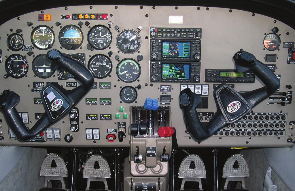
63


64 ATP Purchases 30 Piper Seminoles Piper Aircraft Inc. and Airline Transport Professionals reached agreement at the 2011 NBAA for the sale of as many as 30 Piper Seminoles with a total retail value of $18 million. Beginning in April, 2012, ATP began taking delivery of these aircraft, all equipped with the Garmin G500 glass cockpit avionics suite. Learn more at: ATPFlightSchool.com
DUCHESS BE-76 AND COMMERCIAL MULTI ADD-ON ORAL REVIEW FOR CHECKRIDE
 DUCHESS BE-76 AND COMMERCIAL MULTI ADD-ON ORAL REVIEW FOR CHECKRIDE The Critical Engine The critical engine is the engine whose failure would most adversely affect the airplane s performance or handling
XIV.C. Flight Principles Engine Inoperative
 XIV.C. Flight Principles Engine Inoperative References: FAA-H-8083-3; POH/AFM Objectives The student should develop knowledge of the elements related to single engine operation. Key Elements Elements Schedule
Vso 61. Vs1 63. Vr 70. Vx 76. Vxse 78. Vy 89. Vyse. 89 (blue line) Vmc. 61 (radial redline) Vsse 76. Va 134) Vno 163
 Vmc. 61 (radial redline) Vsse 76. Va 134) Vno 163") PA34-200T Piper Seneca II Normal procedures V-speeds Knots Vso 6 Vs 63 Vr 70 Vx 76 Vxse 78 Vy 89 Vyse Vmc 89 (blue line) 6 (radial redline) Vsse 76 Va 2-36(@4507lbs 34) Vno 63 Vfe 38 (0*)/2(25*)/07(40*)
PA34-200T Piper Seneca II Normal procedures V-speeds Knots Vso 6 Vs 63 Vr 70 Vx 76 Vxse 78 Vy 89 Vyse Vmc 89 (blue line) 6 (radial redline) Vsse 76 Va 2-36(@4507lbs 34) Vno 63 Vfe 38 (0*)/2(25*)/07(40*)
Henley Aviation BE-76 Beechcraft Duchess
 The Problem of Asymmetric Thrust When a Multi-engine aircraft with engines not mounted on the longitudinal axis loses an engine, there will be unbalanced forces and turning moments about the center of
Elmendorf Aero Club Aircraft Test
 DO NOT WRITE ON THIS TEST JAN 2014 Elmendorf Aero Club Aircraft Test SENECA II For the following questions, you will need to refer to the Pilots Information Manual for the PA-34-200T. USE ANSWER SHEET
PA GURW (December 30, 2000) PRE-START. Langley Flying School. Airspeeds (MPH) for Safe Operation. Cockpit Checks
 PRE-START. Langley Flying School. Airspeeds (MPH) for Safe Operation. Cockpit Checks") Langley Flying School PA-34-200 GURW (December 30, 2000) Airspeeds (MPH) for Safe Operation V y (all weights) 105 V x (all weights) 90 En Route Climb 120 V mc 80 V yse 105 V xse 93 V r 80 V r (25 Flaps)
Langley Flying School PA-34-200 GURW (December 30, 2000) Airspeeds (MPH) for Safe Operation V y (all weights) 105 V x (all weights) 90 En Route Climb 120 V mc 80 V yse 105 V xse 93 V r 80 V r (25 Flaps)
PA , Model E Normal Checklist (04/15/11)
") PA-23-250, Model E Normal Checklist (04/15/11) Key Airspeeds IAS-MPH V NE 249 V NO 198 V LO/LE 150 V A (At max gross weight.) 149 Speed for single engine cruise. 138 V FE Quarter Flaps 160 Half Flaps 140
PA-23-250, Model E Normal Checklist (04/15/11) Key Airspeeds IAS-MPH V NE 249 V NO 198 V LO/LE 150 V A (At max gross weight.) 149 Speed for single engine cruise. 138 V FE Quarter Flaps 160 Half Flaps 140
Piper Archer II (PA )
") 1. Oil... 6-8 qts, Cap Secure CABIN 1. POH & Documents.. Check Available 2. Magneto Switch...... OFF 3. Pitot/Static Drains... Push to Drain 4. Avionics/Electrical Switches... OFF 5. Master Switch. ON
1. Oil... 6-8 qts, Cap Secure CABIN 1. POH & Documents.. Check Available 2. Magneto Switch...... OFF 3. Pitot/Static Drains... Push to Drain 4. Avionics/Electrical Switches... OFF 5. Master Switch. ON
FLASHCARDS AIRCRAFT. Courtesy of the Air Safety Institute, a Division of the AOPA Foundation, and made possible by AOPA Services Corporation.
 AIRCRAFT FLASHCARDS Courtesy of the Air Safety Institute, a Division of the AOPA Foundation, and made possible by AOPA Services Corporation. Knowing your aircraft well is essential to safe flying. These
Initial / Recurrent Ground Take-Home Self-Test: The Beechcraft 58 Baron Systems, Components and Procedures
 Initial / Recurrent Ground Take-Home Self-Test: The Beechcraft 58 Baron Systems, Components and Procedures Flight Express, Inc. This take-home self-test partially satisfies the recurrent ground training
CARENADO COPYRIGHTS. Normal & Emergency Checklist
 NORMAL PROCEDURES CHECKLIST PREFLIGHT CHECK Control wheel -- RELEASE BELTS Avionics -- OFF Master Switch -- ON Fuel quantity gauges -- CHECK Master switch -- OFF Ignition -- OFF Exterior -- CHECK FOR DAMAGE
DO NOT WRITE ON THIS TEST FEB 2013 Elmendorf Aero Club Aircraft Test. Cessna - 182
 DO NOT WRITE ON THIS TEST FEB 2013 Elmendorf Aero Club Aircraft Test Cessna - 182 For the following questions, you will need to refer to the Pilots Information Manual for the C-182R. The bonus questions
CESSNA 172S NAV III VFR CHECKOUT POH EXAMINATION (Based on N1129K, serial no. 172S revised 10/05/06)
") INTRODUCTION, POH CESSNA 172S NAV III VFR CHECKOUT POH EXAMINATION (Based on N1129K, serial no. 172S10315 - revised 10/05/06) 1. Rate of climb at sea level: 2. Service ceiling: 3. Takeoff performance,
INTRODUCTION, POH CESSNA 172S NAV III VFR CHECKOUT POH EXAMINATION (Based on N1129K, serial no. 172S10315 - revised 10/05/06) 1. Rate of climb at sea level: 2. Service ceiling: 3. Takeoff performance,
Jump to Table of Contents
 Jump to Table of Contents PIPER AIRCRAFT CORPORATION PA-28R-201, CHEROKEE ARROW III SECTION 3 EMERGENCY PROCEDURES 3.3 EMERGENCY PROCEDURES CHECK LIST ENGINE FIRE DURING
Cessna 172P PPL Checklist Page 1
 Cessna 172P PPL Checklist 06-08-2017 Page 1 Cessna 172P PPL Checklist 06-08-2017 Page 2 Checklist Items Informational Items Critical Memory Items PREFLIGHT COCKPIT CHECK (DO-LIST) Pitot Cover -- REMOVE
CESSNA SECTION 4. Unless otherwise noted, the following speeds are based on a maximum weight of 2550 pounds and may be used for any lesser weight.
 CESSNA SECTION 4 INTRODUCTION Section 4 provides procedures and amplified instructions for normal operations using standard equipment. Normal procedures associated with optional systems can be found in
Interior Pre Flight Documents: Check Control Wheel Lock: Remove Flight Controls: Check Instruments: Check for Damage Switches: Verify All Off Master
 Interior Pre Flight Documents: Check Control Wheel Lock: Remove Flight Controls: Check Instruments: Check for Damage Switches: Verify All Off Master Switch ALT/BAT: On Fuel Gauge: Check Quantity Flaps:
NORMAL PROCEDURRES CHECKLIST PA T SENECA II PREFLIGHT CHECK INSIDE CABIN OUTSIDE CABIN
 NORMAL PROCEDURRES CHECKLIST PA-34-200T SENECA II PREFLIGHT CHECK INSIDE CABIN Avionics Master Switch -- OFF Landing Gear Control. -- DOWN Mixture Controls -- IDLE/CUTOFF Ignition Switches -- OFF Master
CESSNA 182 CHECKLIST. LEFT WING Trailing Edge 1. Aileron CHECK freedom of movement and security
 CESSNA 182 CHECKLIST PRE-FLIGHT INSPECTION CABIN 1. Pilot s Operating Handbook AVAILABLE IN THE AIRPLANE (A.R.R.O.W.E) 2. Landing Gear Lever DOWN 3. Control Wheel Lock REMOVE 4. Ignition Switch OFF 5.
Elmendorf Aero Club Aircraft Test
 DO NOT WRITE ON THIS TEST FEB 2013 Elmendorf Aero Club Aircraft Test Cessna - 182 For the following questions, you will need to refer to the Pilots Information Manual for the C-182R. The bonus questions
N123AX Piper Saratoga II HP (PA-32R-301) Checklist (v23 - Revision 3 April 2011) AIRSPEEDS FOR SAFE OPERATIONS. Best Rate of Climb (gear up, flaps up)
 Checklist (v23 - Revision 3 April 2011) AIRSPEEDS FOR SAFE OPERATIONS. Best Rate of Climb (gear up, flaps up)") N123AX Piper Saratoga II HP (PA-32R-301) Checklist (v23 - Revision 3 April 2011) AIRSPEEDS FOR SAFE OPERATIS Best Rate of Climb (gear down, flaps up) Best Rate of Climb (gear up, flaps up) Turbulent Air
N123AX Piper Saratoga II HP (PA-32R-301) Checklist (v23 - Revision 3 April 2011) AIRSPEEDS FOR SAFE OPERATIS Best Rate of Climb (gear down, flaps up) Best Rate of Climb (gear up, flaps up) Turbulent Air
a. Lycoming IO-520J 250 HP c. Lycoming O-540-J3C5D 235 HP b. Continental O450T 330 HP d. Lycoming O-360A 180 HP
 Three points each question Page 1 of 6 References: Pilot's Operating Handbook for the 1979 Cessna R182 Model; Flying Magazine Article "Cessna 182 Safety Report;" RAFA SOP; and Refueling Instructions found
Elmendorf Aero Club Aircraft Test
 DO NOT WRITE ON THIS TEST FEB 2013 Elmendorf Aero Club Aircraft Test Cessna - 172 For the following questions, you will need to refer to the Pilots Information Manual for the C-172R (180hp). The bonus
Elmendorf Aero Club Aircraft Test
 DO NOT WRITE ON THIS TEST FEB 2014 Elmendorf Aero Club Aircraft Test Cessna - 185 For the following questions, you will need to refer to the Pilots Information Manual for the C-185F and Graphic Engine
PA32-RT LANCE II CHECKLIST
 PA32-RT LANCE II CHECKLIST 6815.10.1112 1 Normal Procedures PREFLIGHT CHECK Control Wheel... RELEASE BELTS Parking brake... Set Master Switch... ON Fuel Quantity Gauges... check Master Switch... OFF Ignition...
CHECKLIST 1969 CESSNA 172-K. NOTE: Verify all information with airplane's POH
 CHECKLIST 1969 CESSNA 172-K NOTE: Verify all information with airplane's POH PRE-FLIGHT INSPECTION 1 CABIN 1 A.R.R.O.W. CHECK Airworthiness Cert. In Clear View Registration In Clear View Radio License
INDEX. Preflight Inspection Pages 2-4. Start Up.. Page 5. Take Off. Page 6. Approach to Landing. Pages 7-8. Emergency Procedures..
 INDEX Preflight Inspection Pages 2-4 Start Up.. Page 5 Take Off. Page 6 Approach to Landing. Pages 7-8 Emergency Procedures.. Page 9 Engine Failure Pages 10-13 Propeller Governor Failure Page 14 Fire.
N1523J CHECKLIST PA Nebraska Flight Center Eppley Airfield 3737 Orville Plaza Omaha, NE Tel. (402)
") CHECKLIST N1523J 1967 Cherokee 140 PA-28-140 F Nebraska Flight Center Eppley Airfield 3737 Orville Plaza Omaha, NE 68110 Tel. (402) 342-4314 www.nebflight.com Piper Cherokee 140 N1523J 1967 GENERAL INFORMATION
CHECKLIST N1523J 1967 Cherokee 140 PA-28-140 F Nebraska Flight Center Eppley Airfield 3737 Orville Plaza Omaha, NE 68110 Tel. (402) 342-4314 www.nebflight.com Piper Cherokee 140 N1523J 1967 GENERAL INFORMATION
Multi-Engine Training Packet
 Multi-Engine Training Packet This multi-engine training course is designed for the Commercial Multi-Engine Rating, MEI and ATP. This packet, in conjunction with the BE-76 Pilot s Operating Handbook contains
V - Speeds. RV-10 V fe Flaps Speeds Trail (0 deg) Half (15 deg) Full (30 deg) 122 kias 96 kias. 80 kias
 Half (15 deg) Full (30 deg) 122 kias 96 kias. 80 kias") RV-10 Check List V - Speeds RV-10 V fe Flaps Speeds Trail (0 deg) Half (15 deg) Full (30 deg) 122 kias 96 kias 87 kias V s1 Stall (Flap Up) 60 kias V s0 Stall (Flap 40 deg) 55 kias Best Glide 80 kias V
RV-10 Check List V - Speeds RV-10 V fe Flaps Speeds Trail (0 deg) Half (15 deg) Full (30 deg) 122 kias 96 kias 87 kias V s1 Stall (Flap Up) 60 kias V s0 Stall (Flap 40 deg) 55 kias Best Glide 80 kias V
Cessna 172 Skyhawk. Aircraft Checklist Models: R & S
 Cessna 172 Skyhawk Aircraft Checklist Models: R & S This is an abbreviated checklist. Most explanatory items, notes cautions and warnings have been omitted for brevity. Procedures in red/bold text in this
GACE Flying Club Aircraft Review Test 2018 N5312S & N5928E. Name: GACE #: Score: Checked by: CFI #:
 GACE Flying Club Aircraft Review Test 2018 N5312S & N5928E Name: GACE #: Score: Checked by: CFI #: Date: (The majority of these questions are for N5312S. All N5928E questions will be marked 28E) 1. What
I. DISPATCH PLANNING & AIRCRAFT EXTERIOR CHECK
 SCHODACK AVIATION Page 1 of 10 I. DISPATCH PLANNING & AIRCRAFT EXTERIOR CHECK 1. Flight Planning 1. Aircraft requirements & preparation: Required aircraft documents: Airworthiness Certificate Registration
EMERGENCY CHECKLIST for N11HC
 OFF AIRPORT LANDING Airspeed / AOA... Vg (2G-1Y ~85 K) Best Field... Into Wind 3 Power Knobs... Aft Fuel Selector... Off Flaps... As Required Slip... As Required Mags... Off Talk... Emergency Squawk...
XIV.D. Maneuvering with One Engine Inoperative
 References: FAA-H-8083-3; POH/AFM Objectives The student should develop knowledge of the elements related to single engine operation. Key Elements Elements Schedule Equipment IP s Actions SP s Actions
The engines are designed to use 100/130 octane fuel. If not available use next higher grade. - 1
 PNEUMATIC SYSTEM The aircraft has a dual pneumatic system. In case of failure of either pneumatic pump, the system will automatically select the operative source. (Inoperative source will be indicated
TECNAM P2004 BRAVO N128LS
 TECNAM P2004 BRAVO N128LS GENERAL INFORMATION NORMAL PROCEDURES TIME SENSITIVE EMERGENCY TECNAM P2004 BRAVO CHECKLIST [FLIGHT PLAN DESIGNATION IS BRAV ] EMERGENCY CONTACT The following are First Landings'
TECNAM P92 EAGLET N615TA TECNAM P92 EAGLET CHECKLIST [FLIGHT PLAN DESIGNATION IS ECHO ]
![TECNAM P92 EAGLET N615TA TECNAM P92 EAGLET CHECKLIST [FLIGHT PLAN DESIGNATION IS ECHO ]](/thumbs/86/93080937.jpg "TECNAM P92 EAGLET N615TA TECNAM P92 EAGLET CHECKLIST [FLIGHT PLAN DESIGNATION IS ECHO ]") TECNAM P92 EAGLET CHECKLIST [FLIGHT PLAN DESIGNATION IS ECHO ] EMERGENCY CONTACT The following are First Landings' emergency contact telephone numbers. We ask that you call the numbers in the order listed.
TECNAM P92 EAGLET CHECKLIST [FLIGHT PLAN DESIGNATION IS ECHO ] EMERGENCY CONTACT The following are First Landings' emergency contact telephone numbers. We ask that you call the numbers in the order listed.
Elmendorf Aero Club Aircraft Test
 DO NOT WRITE ON THIS TEST FEB 2013 Elmendorf Aero Club Aircraft Test Cessna 172RG For the following questions, you will need to refer to the Pilots Information Manual for the C-172RG and the Auxiliary
Expanded Flight Checklist Cessna 152
 OUTSIDE CHECK INSIDE CABIN 1 Magnetos... OFF 2 Mixture... IDLE CUT OFF 3 Master switch... ON 4 Fuel quantity... CHECKED 5 Master switch... OFF OUTSIDE CABIN 1 Left wing... CHECKED Surface condition Flap
Van s Aircraft RV-7A. Pilot s Operating Handbook N585RV
 Van s Aircraft RV-7A Pilot s Operating Handbook N585RV PERFORMANCE SPECIFICATIONS SPAN:..25 0 LENGTH...20 4 HEIGHT:.. 7 10 SPEED: Maximum at Sea Level...180 knots Cruise, 75% Power at 8,000 Ft...170 knots
OPERATIONS MANUAL FTO SECTION : 06.04
 06.04.08. OO-WIK SECTION : 06.04 PARTENAVIA OO-WIK PAGE : 1 PRE ENTRY PITOT COVER - REMOVE SNOW / ICE CHECK AIRCRAFT NOSE INTO WIND AIRCRAFT WEIGHT & BALANCE WITHIN LIMITS EXTERNAL (COCKPIT FIRST) PARK
AIRSPEEDS. Cessna 172R Emergency Checklist
 AIRSPEEDS AIRSPEEDS FOR EMERGENCY OPERATION Cessna 172R Emergency Checklist INTRODUCTION This document provides checklist and amplified procedures for coping with emergencies that may occur. Emergencies
Preflight Inspection Cabin EMPENNAGE RIGHT WING Trailing Edge RIGHT WING NOSE
 Preflight Inspection Cabin 1. Control Wheel Lock REMOVED 2. Ignition Switch OFF 3. Avionics Power Switch OFF 4. Master Switch ON 5. Fuel Quantity Indicators CHECK QUANTITY 6. Master Switch OFF 7. Fuel
NORMAL CHECKLIST ATTENTION!
 Avion Training CHECKLIST Normal Checklist CESSNA 172R / TC-STS Cessna 172 R TC-STS NORMAL CHECKLIST ATTENTION! DO NOT STOW THIS CHECKLIST IN DIRECT SUNLIGHT Avion Training - Doc.nr. 212 Revision 1 / 02022018
RFC Dallas, Inc. AIRCRAFT QUESTIONNAIRE (9/25/2016) "A Safe Pilot Knows His Equipment"
 A Safe Pilot Knows His Equipment") RFC Dallas, Inc. AIRCRAFT QUESTIONNAIRE (9/25/2016) "A Safe Pilot Knows His Equipment" NAME: Date: Aircraft: Cessna 182Q Registration Number: N631S Serial Number: The purpose of this questionnaire is to
RFC Dallas, Inc. AIRCRAFT QUESTIONNAIRE (9/25/2016) "A Safe Pilot Knows His Equipment" NAME: Date: Aircraft: Cessna 182Q Registration Number: N631S Serial Number: The purpose of this questionnaire is to
Normal T/O Procedure. * * * Engine Failure on T/O * * *
 Normal T/O Procedure After adding full power: Engine Instruments green Airspeed alive 1,000 AGL Accelerate to enroute climb 113 KIAS Set climb power Vr 78, but it will come off the ground before Stay in
IN-FLIGHT CHECK LIST B-17 Technical Session for Flight Engineers 11/18/2017 (with REVISION)
") IN-FLIGHT CHECK LIST B-17 Technical Session for Flight Engineers 11/18/2017 (with REVISION) Check Lists became an integral part of aviation following the tragic loss of Boeing 299 the prototype for the
IN-FLIGHT CHECK LIST B-17 Technical Session for Flight Engineers 11/18/2017 (with REVISION) Check Lists became an integral part of aviation following the tragic loss of Boeing 299 the prototype for the
PA28R ARROW CHECKLIST
 PA28R ARROW CHECKLIST 2300.11.0112 1 Normal Procedures Initial PREFLIGHT CHECK General Appearance... CHECKED Position & Taxi Path... CHECKED Tie Downs, Locks, Chocks & Covers... REMOVED Cockpit Controls...UNLOCKED
I. DISPATCH PLANNING & AIRCRAFT EXTERIOR CHECK
 SCHODACK AVIATION Page 1 of 10 I. DISPATCH PLANNING & AIRCRAFT EXTERIOR CHECK 1. Flight Planning 1. Aircraft requirements & preparation: 1. Required aircraft documents: 1. Airworthiness Certificate 2.
COLUMBIA 350 EMERGENCY PROCEDURES
 COLUMBIA 350 EMERGENCY PROCEDURES TABLE OF CONTENTS EMERGENCY PROCEDURES LANDING AND TAKEOFF Engine Failure During Takeoff...1 Engine Failure Immediately After Takeoff...1 Engine Failure During Climb to
Wings of Carolina Flying Club PA Aircraft Type Checkout and Currency Quiz
 Wings of Carolina Flying Club PA-28-161 Aircraft Type Checkout and Currency Quiz Pilot Instructor Score Date Instructor: Please note the final score (subtract 2.5 points from 100 for each wrong answer)
Cessna 152 Checklist
 Cessna 152 Checklist This checklist covers the operation of the model 152. Use at your own risk, the author nor the publisher is responsible for any damage or accidents resulting from the use of this checklist.
LOG OF REVISIONS. Model G58 Baron (Serials TH-2125 and After) Pilot s Operating Handbook and FAA Approved Airplane Flight Manual
 Pilot s Operating Handbook and FAA Approved Airplane Flight Manual") LOG OF REVISIONS Model G58 Baron (Serials TH-2125 and After) Pilot s Operating Handbook and FAA Approved Airplane Flight Manual Revision A12 - May, 2015 Title Page LOEP LOR Section 1 All Reformatted to
LOG OF REVISIONS Model G58 Baron (Serials TH-2125 and After) Pilot s Operating Handbook and FAA Approved Airplane Flight Manual Revision A12 - May, 2015 Title Page LOEP LOR Section 1 All Reformatted to
PA34-220T Piper Seneca III
 PREFLIGHT PA34-220T Piper Seneca III Weight and Balance Documents -Airworthiness Certificate -Registration -Airplane Flight Manual -Weight & Balance Hobbs/Time Landing Gear Avionics and Fan(s) Cowl Fuel
2. What type and size (hp) engine does the airplane have? Lycoming O540-JC35D rated at 235 BHP at 2400 RPM
 engine does the airplane have? Lycoming O540-JC35D rated at 235 BHP at 2400 RPM") This quiz will help test your knowledge of the POH and the systems and equipment in CR-182 N133BW. In preparation for your checkout flight, answer all of the following questions as thoroughly as possible
This quiz will help test your knowledge of the POH and the systems and equipment in CR-182 N133BW. In preparation for your checkout flight, answer all of the following questions as thoroughly as possible
PA-28R 201 Piper Arrow
 Beale Aero Club Aircraft Written Test PA-28R 201 Piper Arrow (Required passing score: 80%) 1. If an engine power loss occurs immediately after take off, the pilot s reaction should be to: a. maintain safe
King Air B90. Speeds (KIAS)
") King Air B90 Speeds (KIAS) V MCA 92 V SSE (101) Derived from C90 V X 101 V Y 114 Down to 103 @ 30 000 V XSE 101 V YSE 110 Down to 101 @ 24 000 V A 169 V R 92 V 1 101 V MO 208 V FE 174 35% 130 100% V LE
King Air B90 Speeds (KIAS) V MCA 92 V SSE (101) Derived from C90 V X 101 V Y 114 Down to 103 @ 30 000 V XSE 101 V YSE 110 Down to 101 @ 24 000 V A 169 V R 92 V 1 101 V MO 208 V FE 174 35% 130 100% V LE
EGLIN AERO CLUB C-172 OPEN BOOK EXAMINATION Apr Total usable fuel capacity for the aircraft with long range tanks is:
 (The following questions are taken from the C-172N POH) 1. Total usable fuel capacity for the aircraft with long range tanks is: a. 54 gallons b. 50 gallons c. 62 gallons d. 40 gallons 2. Total fuel capacity
3. What is the total fuel capacity with normal tanks? Usable? 4. What is the total fuel capacity with long range tanks? Usable?
 Pilot Name: Last, first, mi. Date: (mo/dy/yr) Instructor: Pass/Fail: Instructors Initials: 1. What is the engine Manufacturer: Model: Type: 2. What is the horsepower rating? 3. What is the total fuel capacity
Aircraft Checklist Commander 114
 Aircraft Checklist Commander 114 This is an abbreviated checklist. Most explanatory items, notes cautions and warnings have been omitted for brevity. Procedures in red/bold text in this checklist should
Aircraft Checklist Cessna 182T
 Aircraft Checklist Cessna 182T This is an abbreviated checklist. Most explanatory items, notes cautions and warnings have been omitted for brevity. Procedures in red/bold in this checklist should be committed
Pilot's Operating Handbook Supplement AS-03
 POH / AFM SECTION 9 Pilot's Operating Handbook Supplement ASPEN EFD1000 PFD This supplement is applicable and must be inserted into Section 9 of the POH when the Aspen Avionics Evolution Flight Display
Systems PA28R-201 ARROW. Engine. Make : Avco Lycoming. Model: IO-360 C1C6. Type:
 1 Systems PA28R-201 ARROW Engine Make : Avco Lycoming Model: Type: IO-360 C1C6 4 cylinders Horizontally opposed Normally aspirated(no turbo charge) Air cooled (Engine oil and fuel helps cooling) Direct
FIRST FLYING TECHNIQUES COCKPIT PREPARATION STARTUP TAXI
 1. Introduction FIRST FLYING TECHNIQUES COCKPIT PREPARATION STARTUP TAXI We aim to teach and demonstrate how to operate a general aviation aircraft and show some basic techniques and manoeuvres that every
CESSNA 182 TRAINING MANUAL. Trim Control Connections
 Trim Control Connections by D. Bruckert & O. Roud 2006 Page 36 Flaps The flaps are constructed basically the same as the ailerons with the exception of the balance weights and the addition of a formed
RFC Dallas, Inc. AIRCRAFT QUESTIONNAIRE (6/3/2018) "A Safe Pilot Knows His Equipment"
 A Safe Pilot Knows His Equipment") RFC Dallas, Inc. AIRCRAFT QUESTIONNAIRE (6/3/2018) "A Safe Pilot Knows His Equipment" NAME: Date: Aircraft: Bonanza Registration Number: Serial Number: The purpose of this questionnaire is to aid the pilot
RFC Dallas, Inc. AIRCRAFT QUESTIONNAIRE (6/3/2018) "A Safe Pilot Knows His Equipment" NAME: Date: Aircraft: Bonanza Registration Number: Serial Number: The purpose of this questionnaire is to aid the pilot
CESSNA 172I CESSNA 172I PREFLIGHT INSPECTION
 PREFLIGHT INSPECTION Visually check airplane for general condition during walk-around inspection. In cold weather, remove even small accumulations of frost, ice or snow from wing, tail and control surfaces.
Checklist LN-DAG SFK 2014
 Checklist LN-DAG SFK 2014 2 GROUND Exsterior Checklist 1. Fuel (wings & filter) - Drained 2. Documents - Checked 3. Fire extinguisher, first aid sur. kit - Checked 4. Magnetos - Off 5. Master switch -
If, nonetheless, an emergency does arise, the guidelines given here should be followed and applied in order to clear the problem.
 3.1 INTRODUCTION 3.1.1 GENERAL This Chapter contains checklists as well as the description of recommended procedures to be followed in the event of an emergency. Engine failure or other airplane-related
PA WARRIOR II Quick Reference Handbook
 PA28-161 WARRIOR II Quick Reference Handbook Version 1.0 ALL GREY SHADED AREAS ARE MEMORY ITEMS Normal Procedures Pre-Flight Check... N-1 Before Start... N-3 Flooded Engine Start... N-4 Starting With
The Straight Word. Cessna 208 Caravan 208 Caravan I & 208B Grand Caravan Series
 The Straight Word Cessna 208 Caravan 208 Caravan I & 208B Grand Caravan Series I. FLIGHT PROCEDURES: COCKPIT PREPARATION Fuel Tank Selectors Ignition Switch Heading Bug HSI Course Indicator Altimeters
Pilot s Checklist PIPER ARROW PA-28R-201
 Pilot s Checklist PIPER ARROW PA-28R-201 Original Issue 10/31/2012 REVISIONS Changes and/or additions in this checklist will be covered by Owner Advisories published by the Piper Aircraft Corporation.
QUICK REFERENCE HANDBOOK TECNAM P92 ECHO
 NORMAL LISTS PRE-START S Park brake Left fuel cock Flight Instruments (No broken glass or bent needles) Engine Instruments (No broken glass or bent needles) Right fuel cock Fuses Landing Light Avionics
Cessna 182S-CHECKLIST PROCEDURES
 Cessna 182S-CHECKLIST PROCEDURES PREFLIGHT INSPECTION 1 CABIN 1. Pitot Tube Cover -- REMOVE (if installed) and check for stoppage 2. Pilot s Operating Handbook AVAILABLE IN THE AIRPLANE 3. Airplane Weight
INDEX: Normal Procedures Emergency Procedures Pre Flight Inspection NORMAL PROCEDURES BEFORE STARTING ENGINE
 INDEX: Normal Procedures Emergency Procedures Pre Flight Inspection NORMAL PROCEDURES BEFORE STARTING ENGINE 1. Preflight Inspection -- COMPLETE 2. Seats, Belts, Shoulder Harnesses -- ADJUST and LOCK 3.
CESSNA 172N 08E/97E CESSNA 172N 08E/97E PREFLIGHT INSPECTION
 PREFLIGHT INSPECTION Visually check airplane for general condition during walk-around inspection. In cold weather, remove even small accumulations of frost, ice or snow from wing, tail and control surfaces.
Checklist for Bellanca Viking N4880V (Speeds in MPH (KTS) IAS)
 IAS)") V-SPEEDS Checklist for Bellanca Viking N4880V V SO 62 (54) Stall Full Flaps V S1 72 (63) Stall Clean V R 80 (70) Takeoff Rotation Flaps Up V Y 110 (96) Best Rate Gear Up & Flaps Up V R 70 (61) Takeoff
V-SPEEDS Checklist for Bellanca Viking N4880V V SO 62 (54) Stall Full Flaps V S1 72 (63) Stall Clean V R 80 (70) Takeoff Rotation Flaps Up V Y 110 (96) Best Rate Gear Up & Flaps Up V R 70 (61) Takeoff
AIRPLANE FLIGHT MANUAL AQUILA AT01 AIRPLANE FLIGHT MANUAL - SUPPLEMENT AVE28 GLASS COCKPIT. equipped with ASPEN EFD1000 PFD
 SECTION 9 AIRPLANE FLIGHT MANUAL - SUPPLEMENT AVE28 GLASS COCKPIT equipped with ASPEN EFD1000 PFD This AFM supplement is applicable and must be inserted into Section 9 of the Airplane Flight Manual when
PIPER SENECA II (N39522)
") PIPER SENECA II () FLIGHT CREW CHECKLIST PIPER SENECA II CHECKLIST DATA AND INFORMATION IN THIS CHECKLIST IS OBTAINED FROM SEVERAL DIFFERENT SOURCES AND IS PRESENTED ONLY AS A GUIDE. THE PILOT IS RESPONSIBLE
PIPER SENECA II () FLIGHT CREW CHECKLIST PIPER SENECA II CHECKLIST DATA AND INFORMATION IN THIS CHECKLIST IS OBTAINED FROM SEVERAL DIFFERENT SOURCES AND IS PRESENTED ONLY AS A GUIDE. THE PILOT IS RESPONSIBLE
PA ARCHER II Quick Reference Handbook
 PA28-180 ARCHER II Quick Reference Handbook ALL GREY SHADED AREAS ARE MEMORY ITEMS 7813.03.0116 1 Table of Contents Normal Procedures... 4 PREFLIGHT CHECK... 4 BEFORE START... 6 FLOODED ENGINE START...
EMERGENCY PROCEDURES PA44
 ENGINE FAILURES ENGINE FAILURE DURING TAKEOFF ROLL *REQUIRES IMMEDIATE ACTION FROM MEMORY* Throttles....IMMEDIATELY CLOSE Maintain Directional Control Brakes..AS REQUIRED Stop straight ahead or exit runway
Vr V STANDARD EQUIPMENT LIST
 Vr V5.02.09 STANDARD EQUIPMENT LIST IMPORTANT NOTE: this document is a general description of the aircraft equipment only. It is not a technical document and is to be used only for the purpose of generally
Owners Manual. Table of Contents 3.1. INTRODUCTION AIRSPEEDS FOR EMERGENCY OPERATION OPERATIONAL CHECKLISTS 3
 EMERGENCY PROCEDURES Table of Contents 3.1. INTRODUCTION 2 3.2. AIRSPEEDS FOR EMERGENCY OPERATION 2 3.3. OPERATIONAL CHECKLISTS 3 3.3.1. ENGINE FAILURES 3. ENGINE FAILURE DURING TAKEOFF RUN 3. ENGINE FAILURE
FLIGHT TEST PROGRAM YOUR AIRPLANE HERE FLIGHT TEST PROGRAM YOUR AIRPLANE HERE
 Flight #: 1 FIRST TEST FLIGHT Validate Engine Reliability Explore Flight Control Characteristics Do not use flaps Do not change throttle settings, mixture, or fuel tanks Remain above the airport Climb
SECTION 3 EMERGENCY PROCEDURES
 SECTION 3 TABLE OF CONTENTS Page Introduction... 3-3 Airspeeds for Emergency Operation... 3-5 CHECKLISTS Engine Failures... 3-6 Engine Failure During Takeoff Run... 3-6 Engine Failure Immediately After
DIAMOND DA40 PILOTS MANUAL
 DIAMOND DA40 PILOTS MANUAL INTRODUCTION THIS IS THE SLEEK AND FUTURISTIC DIAMOND STAR DA40 XLS BY DIAMOND AIRCRAFT CORPORATION. THE DIAMOND STAR FEATURES 4 SEATS, AND OPTIONAL EXPANDED REAR CARGO AREA,
HU-16 Albatross USER MANUAL. Virtavia HU-16 Albatross DTG Steam Edition Manual Version 1.0
 HU-16 Albatross USER MANUAL 0 Introduction The Grumman HU-16 Albatross is a twin-engine amphibious flying boat. First flown in 1949, the HU-16 underwent a number of modifications and improvements over
Central Warning Systems
 CIRRUS AIRPLANE MAINTENANCE MANUAL Central Warning Systems CHAPTER 31-50: CENTRAL WARNING SYSTEMS GENERAL 31-50: CENTRAL WARNING SYSTEMS 1. General This section describes the Indicating/Recording Systems
CESSNA P 337 H Pressurized Skymaster
 CESSNA P 337 H Pressurized Skymaster N777SN Quick reference training guide This training manual cannot be used as a substitute for the official pilots operating handbook. Page 1 - 1. Take off (normal)
Name: GACE #: Score: Checked by: CFI #: 1. What is the total fuel capacity? Usable: /Section: Page:
 GACE Flying Club Aircraft Review Test, 2016 N5312S Date: Name: GACE #: Score: Checked by: CFI #: Date: (Information for all answers can be found in the 172S POH) 1. What is the total fuel capacity? Usable:
N955DK RV-8A David B. Kumhyr. N955DK Version 05Nov04 RV-8A
 N955DK RV-8A David B. Kumhyr Operating Speeds Reference VREF Flight Regime Kts Mph Vso Stall, dirty (gross)... Stall, dirty (solo).. 50 58 Vs.. Stall, clean (gross)... Stall, clean (solo). 55 63 Vr.. Rotation.
CHAPTER 7 ABNORMAL FLOWS AND CHECKLISTS TABLE OF CONTENTS
 CHAPTER 7 ABNORMAL FLOWS AND CHECKLISTS TABLE OF CONTENTS ELECTRICAL FAULTS...3 Alternator Failure / Low Voltage...3 INSTRUMENTS...7 Low vacuum indication / vacuum failure...7 Erroneous airspeed / altitude
EMERGENCY PROCEDURES ENGINE FIRE DURING START/GROUND OPERATIONS STARTER ENERGIZED ANNUNCIATOR ILLUMINATED. Memory items are printed in red.
 ENG FIRE-GRND, STARTER ENERGIZED EMERGENCY PROCEDURES Memory items are printed in red. ENGINE FIRE DURING START/GROUND OPERATIONS 1. Mixture...IDLE CUTOFF 2. Fuel Selector Valve... OFF 3. Battery, Alternator,
PREFLIGHT CHECKLIST PA28R-200
 PREFLIGHT CHECKLIST PA28R-200 COCKPIT AND CABIN MAINTENANCE STATUS VERIFIED / CLEARED HOBBS / TACH METERS VERIFIED / RECORDED POH / AIRCRAFT DOCUMENTS AVAILABLE / PARKING BRAKE SET FLIGHT CONTROLS FREE
M20J-201 Checklist BEFORE STARTING ENGINE
 M20J-201 Checklist BEFORE STARTING ENGINE Preflight... COMPLETE Baggage door... LATCHED/LOCKED Door... LATCHED/LOCKED Seatbelts... FASTENED Passenger brief....... [seatbelts/exits/smoking/talking/traffic]
LIMITING SPEEDS. DECISION SPEEDS (V 1 ) Confined Runways MPH Non-confined Runways MPH
 Confined Runways MPH Non-confined Runways MPH") PA34-200 GURW Version 17-02 AIRSPEEDS (MPH) FOR SAFE OPERATION V y (all weights)... 105 V x (all weights)... 90 En Route Climb... 120 V mc... 80 V yse... 105 V xse... 93 V r... 80 V r (25 Flaps)... 70
PA34-200 GURW Version 17-02 AIRSPEEDS (MPH) FOR SAFE OPERATION V y (all weights)... 105 V x (all weights)... 90 En Route Climb... 120 V mc... 80 V yse... 105 V xse... 93 V r... 80 V r (25 Flaps)... 70
Cessna 172RG WARNING. Maximum Demonstrated Crosswind. Takeoff or landing..15 KTS
 Cessna 172RG INTRODUCTION: This aircraft checklist contains information from the original manufacturer s Pilot Information Manual. Normal procedures associated with optional systems can be found in Section
PREFLIGHT CHECK COCKPIT RIGHT WING. NORMAL PROCEDURRES CHECKLIST PA-28RT 201 Arrow IV
 NORMAL PROCEDURRES CHECKLIST PA-28RT 201 Arrow IV PREFLIGHT CHECK COCKPIT Control Wheel -- Release Restraints Avionics -- OFF Parking Brake -- SET All Switches -- OFF Mixture -- IDLE CUT-OFF Master Switch
AIRCRAFT FAMILIARIZATION. Some questions may not apply to the aircraft you are flying.
 541-895-5935 Name Date AIRCRAFT FAMILIARIZATION Note: If this information is not provided in the aircraft s flight manual give it your best guess. Some questions may not apply to the aircraft you are flying.