Linear Guideway General Catalog
|
|
|
- Derrick Grant
- 6 years ago
- Views:
Transcription

1 General Catalog
2 General Catalog
3 Index TY AG Contents Technical roducts TY AG The Characteristics of MI s 2. The Classifi cation Chart of MI s 3. The rocedure of Select 4. oad Rating and Service ife of 4.1 Basic Static oad Rating (C ) 4.2 Static ermissible Moment (M ) 4.3 Static Safety Factor ( f s ) 4.4 Basic Dynamic oad Rating (C ) 4.5 Calculation of Nominal ife 4.6 Calculation of Service ife in Time 5. Friction Coeffi cient 6. Calculation of orking oad 7. Calculation of the quivalent oad 8. The Calculation of the Mean oad Calculation xample 9.1 Calculate the load that each carriage exerts 9.2 Calculate equivalent load 9.3 Calculation of static factor 9.4 Calculate the mean load on each carriage m n 9.5 Calculation of nominal life (n) 1. Accuracy Standard 1.1 The Selection of Accuracy Grade 1.2 Accuracy Standard for ach Series 11. reload and Rigidity 11.1 The Selection of reload Grade 11.2 reload Standard for ach Series Introduction for ach Series 12.1 MSA Series - eavy oad Type 12.2 MSB Series - Compact Type 12.3 MSR Series - Full Roller Type 12.4 MSC Series Miniature Type 12.5 SM Series Ball Chain Type 12.6 SMR Series - Roller Chain Type 13. Reference of Design 13.1 Installation Direction of 13.2 Fixing Methods of 13.3 The Design of Mounting Surface 14. Installation of 14.1 Installation of hen Machine Subjected to Vibration and Impact 14.2 Installation of without ush Screws 14.3 The Installation of Carriage of without the Reference Side for Master Rail 14.4 Accuracy Measurement after Installation 14.5 The Recommended Tightening Torque for Rails 15. Options Dust roof 15.2 ubrication 16. recautions of 17. MI Request Form 2 Contents General Catalog 3
4
5 1 The Characteristics of MI s The Classification Chart of MI s 2 (1) igh positioning accuracy, high repeatability The MI linear guideway is a design of rolling motion with a low friction coefficient, and the difference between dynamic and static friction is very small. Therefore, the stick-slip will not occur when submicron feeding is making. (2) ow frictional resistance, high precision maintained for long period The frictional resistance of a linear guideway is only 1/2th to 1/4th of that in a slide guide. ith a linear guideway, a well lubrication can be easily achieved by supplying grease through the grease nipple on carriage or utilizing a centralized oil pumping system, thus the frictional resistance is decreased and the accuracy could be maintained for long period. (3) igh rigidity with four-way load design The optimum design of geometric mechanics makes the linear guideway to bear the load in all four directions, radial, reversed radial, and two lateral directions. Furthermore, the rigidity of linear guideway could be easily achieved by preloading carriage and by adding the number of carriages. (4) Suitable for high speed operation Due to the characteristic of low frictional resistance, the required driving force is much lower than in other systems, thus the power consumption is small. Moreover, the temperature rising effect is small even under high speed operation. Type Model Characteristics Major Application Full Ball, eavy oad Type Full Ball, Compact Type MSA-A MSA-A MSA- MSA- MSA-S MSA-S MSB-T MSB- MSB-TS MSB-S eavy oad, igh Rigidity Self Alignment Capability Smooth Movement ow Noise Interchangeability Compact, igh oad Self Alignment Capability Smooth Movement ow Noise Interchangeability Machine Center, NC lathe, XYZ axes of heavy cutting machine tools, Grinding head feeding axis of grinding machines, Milling machine, Z axis of boring machine and machine tools, DM, Z axis of industrial machine, Measuring equiement, recision XY table, elding machine, Binding machine, Auto packing machine (5) asy installation with interchangeability Compared with the high-skill required scrapping process of conventional slide guide, the linear guideway can offer high precision even if the mounting surface is machined by milling or grinding. Moreover the interchangeability of linear guideway gives a convenience for installation and future Full Ball, Miniature Type MSC Ultra Compact Smooth Movement ow Noise Ball Retainer Interchangeability IC/SI manufacturing machine, ard disc drive, Slide unit of OA equipment, afer transfer equipment, rinted circuit board assembly table, Medical equipment, Inspection equipment maintenance. 6 The Characteristics of MI s General Catalog 7


6 Type Model Characteristics Major Application MSR- Full Roller, eavy oad Type MSR- MSR-S Ultra eavy oad Ultra igh Rigidity Smooth Movement ow Noise Good lubricant ffect Machine Center, NC lathe, Griding machine, Five axes milling machine, Jig borer, Drilling machine, orizontal milling machine, Mold processing machine, DM MSR-S SM- eavy oad, igh Rigidity Machine Center, NC lathe, XYZ axes of heavy Ball Chain, eavy oad Type SM- SM-S Self Alignment Capability Ball Chain Design Smooth Movement ow Noise, Good ubricant ffect cutting machine tools, Grinding head feeding axis of grinding machines, milling machine, Z axis of boring machine and machine tools, DM, Z axis of industrial machine, Measuring equiement, recision XY table, elding machine, Binding SM-S Interchangeability machine, Auto packing machine SMR- SMR- Ultra eavy oad Ultra igh Rigidity Machine Center, NC lathe, Griding machine, Five Roller Chain, Roller Chain Design axes milling machine, Jig borer, Drilling machine, eavy oad Type Smooth Movement orizontal milling machine, Mold processing SMR-S ow Noise Good ubricant ffect machine, DM SMR-S 8 The Classification Chart of MI s General Catalog 9
7 3 The rocedure of Select oad Rating and Service ife of 4 span, No. of carriages, No. of rails change Type or size changed Identify the operating conditions Select type Calculate the applied load Calculate the equivalent load arameters for calculating load on the linear guideway Space available for installation Size (span, No. of carriages, No. of rails) Installation position (horizontal, vertical, tilted, or wallhung, etc.) Magnitude, direction, and location of imposed load Frequency of use (duty cycle) Stroke length Moving speed, acceleration Required service life, and accuracy Operating environment Select proper type and size (If applied with ballscrew, the size of guideway should be similar to diameter of ballscrew.) Calculate the load applied on each carriage Convert the load of block exerts in each direction into equivalent load To obtain a model which is most suitable for your service conditions of the linear guideway system, the load capacity and service life of the model must be taken into consideration. To verify the static load capacity, the basic static load rating (C) is taken to obtain the static safety factor. The service life can be obtained by calculating the nominal life based on basic dynamic load rating. As the raceways or rolling elements are subjected repeated stresses, the service life of a linear guideway is defined as the total running distance that the linear guideway travel until flaking occurs. 4.1 Basic Static oad Rating (C) A localized permanent deformation will develop between raceways and rolling elements when a linear guideway receives an excessive load or a large impact. If the magnitude of the deformation exceeds a certain limit, it could obstruct the smooth motion of the linear guideway. The basic static load rating (C) refers to a static load in a given direction with a specific magnitude applied at the contact area under the most stress where the sum of permanent deformation develops between the raceway and rolling elements is.1 times of the diameter of rolling ball. Therefore, the basic static load rating sets a limit on the static permissible load. 4.2 Static ermissible Moment (M) Calculate the static safety factor The safety factor verified by basic static load rating and max equivalent load hen a moment is applied to a linear guideway, the rolling balls on both ends will receive the most stress among the stress distribution over the rolling elements in the system. The static permissible moment (M) refers to a static NO Verification of safety factor moment in a given direction with specific magnitude applied at the contact area under the most stress where the sum of permanent deformation develops between the raceway and rolling elements is.1 times the diameter YS of rolling elements. Therefore, the static permissible moment sets a limit on the static moment. In linear guideway Calculate mean load Averaging the applied loads that fluctuate during operation and convert them into mean load system, the static permissible moment is defined as M, MY, MR three directions. See the figure below. NO Calculate nominal life Using the service-life equation to calculate the running distance or hours Does the calculated value satisfy the required service life M R M YS Identify stiffness Select preload Determine the fastening methods Determine the rigidity of fastened area M Y Identify accuracy ubrication and dust protection Select accuracy grade Identify the precision of mounting surface Types of lubrication (grease, oil, special lubrication) Method of lubrication (periodic or forced lubrication) Dust prevention design. Completion 1 The rocedure of Select General Catalog 11
8 4.3 Static Safety Factor ( fs ) Due to the impact and vibration while the guideway at rest or moving, or the inertia from start and stop, the linear guideway may encounter with an unexpected external force. Therefore, the safety factor should be taken into consideration for effects of such operating loads. The static safety factor ( fs) is a ratio of the basic static load rating (C) to the calculated working load. The static safety factor for different kinds of application is shown as Table. Machine Type oad Condition fs (ower limit) Regular industrial Normal loading condition 1. ~ 1.3 machine ith impact and vibration 2. ~ 3. Normal loading condition 1. ~ 1.5 Machine tool ith impact and vibration 2.5 ~ 7. Standard value of static safety factor 4.4 Basic Dynamic oad Rating (C ) ven when identical linear guideways in a group are manufactured in the same way or applied under the same condition, the service life may be varied. Thus, the service life is used as an indicator for determining the service life of a linear guideway system. The nominal life () is defined as the total running distance that 9% of identical linear guideways in a group, when they are applied under the same conditions, can work without developing flaking. The basic dynamic load rating (C ) can be used to calculate the service life when linear guideway system response to a load. The basic dynamic load rating (C ) is defined as a load in a given direction and with a given magnitude that when a group of linear guideways operate under the same conditions. As the rolling element is ball, the nominal life of the linear guideway is 5 km. Moreover, as the rolling element is roller, the nominal life is 1 km. 4.5 Calculation of Nominal ife () The nominal life of a linear guideway can be affected by the actual working load. The nominal life can be calculated base on selected basic dynamic load rating and actual working load. The nominal life of linear guideway system could be influenced widely by environmental factors such like hardness of raceway, environmental temperature, motion conditions, thus these factors should be considered for calculation of nominal life. ardness factor f In order to ensure the optimum load capacity of linear guideway system, the hardness of raceway must be RC58~64. If the hardness is lower than this range, the permissible load and nominal life will be decreased. For this reason, the basic dynamic load rating and the basic static load rating should be multiplied by hardness factor for rating calculation. See figure below. The hardness requirement of MI linear guideway is above RC58, thus the f =1.. ardness factor ( f ) Raceway hardness (RC) oad factor f w Although the working load of liner guideway system can be obtained by calculation, the actual load is mostly higher than calculated value. This is because the vibration and impact, caused by mechanical reciprocal motion, are difficult to be estimated. This is especially true when the vibration from high speed operation and the impact from repeated start and stop. Therefore, for consideration of speed and vibration, the basic dynamic load rating should be divided by the empirical load factor. See the table below. Temperature factor f T hen operating temperature higher than 1, the nominal life will be degraded. Therefore, the basic dynamic and static load rating should be multiplied by temperature factor for rating calculation. See figure below. The assemble parts of MI guideway are made of plastic and rubber, therefore, the operating temperature below 1 is strongly recommend. For special need, please contact us. Temperature factor ( ft ) Motion Condition Operating Speed f No impact & vibration V 15 m/min 1.~1.2 Slight impact & vibration 15 V 6 m/min 1.2~1.5 Moderate impact & vibration Raceway temperature( ) 6 V 12 m/min 1.5~2. Strong impact & vibration V 12 m/min 2.~3.5 Ball C Nominal life (km) Basic dynamic load rating (N) orking load (N) 4.6 Calculation of Service ife in Time ( h ) hen the nominal life () is obtained, the service life in hours can be calculated by using the following equation when stroke length and reciprocating cycles are constant. Roller f f T f ardness factor Temperature factor oad factor h l S Service life in hours (hr) Nominal life (km) Stroke length (m) n 1 No. of reciprocating cycles per minute (min -1 ) 12 oad Rating and Service ife of General Catalog 13
9 5 Friction Coefficient Calculation of orking oad 6 A linear guideway manipulates linear motion by rolling elements between the rail and the carriage. In which type of motion, the frictional resistance of linear guideway can be reduced to 1/2th to 1/4th of that in a slide guide. This is especially true in static friction which is much smaller than that in other systems. Moreover, the difference between static and dynamic friction is very little, so that the stick-slip situation does not occur. As such low friction, the submicron feeding can be carried out. The frictional resistance of a linear guideway system can be varied with the magnitude of load and preload, the viscosity resistance of lubricant, and other factors. The frictional resistance can be calculated by the following equation base on working load and seals resistance. Generally, the friction coefficient will be different from series to series, the friction coefficient of ball type is.2~.3 (without considering the seal resistance) and the roller type is.1~.2(without considering the seal resistance) The load applied to a linear guideway system could be varied with several factors such as the location of the center gravity of an object, the location of the thrust, and the inertial forces due to acceleration and deceleration during starting and stopping. To select a correct linear guideway system, the above conditions must be considered for determining the magnitude of applied load. xamples for calculating working load Type Operation Conditions quations 3 l2 F Frictional resistance (kgf ) μ Dynamic friction coefficient orizontal application: 4 l3 F 2 orking load (kgf ) Uniform motion f Seal resistance (kgf ) or at rest 1 l4 l1.15 Friction coefficient ( ).1.5 Overhung horizontal application: Uniform motion l2 or at rest l1.1.2 l4 F l3 oad ratio (/C) : orking load C: Basic dynamic load rating l3 Relationship between working load and friction coefficient 4 F Vertical 1 application: l1 1T Uniform motion or at rest 3 l4 2 2T l2 14 Friction Coefficient General Catalog 15
10 Type Operation Conditions quations Type Operation Conditions quations l1 mg 2T During acceleration l2 1T 2 all installation l4 1 3 application: 1 l4 Uniform motion or at rest 3T 3 orizontal application: l3 4 l1 3T In uniform motion F 4T l3 4 Subjected to inertia l2 4T V (m/s) an = V tn During deceleration h1 F Velocity t1 t2 t3 t(s) Time aterally tilted 3 1 Velocity diagram application l4 2 l3 1T l3 l2 2T l1 4 mg During acceleration 1 l1 1T 3 Vertical application: 3 l4 In uniform motion ongitudinally tilted application h1 4 F 1 2 l3 2T Subjected to inertia 2T 2 l2 V (m/s) V an= tn During deceleration l2 l4 1T l1 Velocity t1 t2 t3 Velocity diagram t(s) Time 16 Calculation of orking oad General Catalog 17
11 7 Calculation of the quivalent oad The Calculation of the Mean oad 8 The linear guideway system can take up loads and moments in all four directions those are radial load, reverse-radial load, and lateral load simultaneously. hen more than one load is exerted on linear guideway system simultaneously, all loads could be converted into radial or lateral equivalent load for calculating service life and static safety factor. hen a linear guideway system receives varying loads, the service life could be calculated in consideration of varying loads of the host-system operation conditions. The mean load (m) is the load that the service life is equivalent to the system which under the varying load conditions. The equation of mean load is: MI linear guideway has four-way equal load design. The calculation of equivalent load for the use of two or more m Mean load (N) linear guideways is shown as below. n Varying load (N) Total running distance (mm) n Running distance under load n (mm) R xamples for calculating mean load T Types of Varying oad Calculation of Mean oad quivalent load (N) oads that 1 R Radial or reverse-radial load (N) change stepwise T ateral load (N) m 2 For the case of mono rail, the moment effect should be considered. The equation is: oad () 1 2 n n Mean load (N) Varying load (N) Total running distance (mm) Running distance under load n (mm) Total running distance () oads that change monotonously m quivalent load (N) MR R T C Radial or reverse-radial load (N) ateral load (N) Basic static load rating (N) min oads that change sinusoidally max Mean load (N) M Calculated moment (N. m) R T Minimum load (N) Maximum load (N) M R ermissible static moment (N. m) max max m m Mean load (N) Maximum load (N) Mean load (N) Maximum load (N) 18 Calculation of the quivalent oad General Catalog 19
12 9 Calculation xample Operation conditions Modle MSA35A2SSFC + R252-2/2 II Basic dynamic load rating C = 63.6 kn Basic static load rating C = 1.6 kn m1g l5 l6 Mass Velocity Time Acceleration m 1 = 7 kg m 2 = 45 kg V =.75 m/s t 1 =.5 s t 2 = 1.9 s t 3 =.15 s a 1 = 15 m/s 2 a 3 = 5 m/s 2 Stroke Distance l s = 15 mm l 1 = 65 mm l 2 = 45 mm l 3 = 135 mm l 4 = 6 mm l 5 = 175 mm l 6 = 4 mm ateral load t n la During deceleration to the left, Radial load n la 3 eft m2g V (m/s) No.1 l4 l3 No.3 l2 l1 t1 t2 t3 X1 X2 X3 ls t (s) (mm) (mm) No.4 Velocity diagram ateral load t n la Calculate the load that each carriage exerts Uniform motion, Radial load n During acceleration to the right, Radial load n ra During acceleration to the left, Radial load n la 1 ateral load t n ra 1 2 Calculation xample General Catalog 21
13 9.1.5 During deceleration to the right, Radial load n ra Calculation of static factor From above, the maximum load is exerted on carriage No.2 when during acceleration of the 2nd linear guideway to the left. 9.4 Calculate the mean load on each carriage m n ateral load t n ra Calculate equivalent load In uniform motion During acceleration to the left 9.5 Calculation of nominal life ( n ) Base on the equation of the nominal life, we assume the f =1.5 and the result is as below: During deceleration to the left During acceleration to the right From these calculations and under the operating conditions specified as above, the km running distance as service life of carriage No.2 is obtained During deceleration to the right 22 Calculation xample General Catalog 23
14 1 Accuracy Standard The accuracy of linear guideway includes the dimensional tolerance of height, width, and the running accuracy of the carriage on the rail. The standard of the dimension difference is built for two or more carriages on a rail or a number of rails are used on the same plane. The accuracy of linear guideway is divided into 5 classes, normal grade (N), high 1.1 The Selection of Accuracy Grade The accuracy grade for different applications shown as table below. precision (), precision (), super precision (S), and ultra precision (U). Running parallelism Sort Application Accuracy Grade N S U Sort Application Accuracy Grade N S U The running accuracy is the deviation of parallelism between the reference surface of carriage and reference surface of rail when carriage moving over the entire length of rail. Machining center athe Milling machine Boring machine Industrial Robot Cartesian coordinate robot Cylindrical coordinate robot Jig borer ire bonder eight difference (Δ) The height difference (Δ) means the height difference among carriages installed on the same plane. 2 Machine Tool Grinding machine lectric discharge machine unching press aser-beam machine oodworking machine NC drilling machine Semiconductor Manufacturing rober lectroniccomponent inserter rinted-circuitboard drilling machine Injection-molding machine 3D measuring instrument Office equipment idth difference (Δ 2 ) The width difference (Δ2) means the width difference among carriages installed on a rail. Tapping center allet changer ATC Others Transfer equipment XY table ainting machine Additional remarks 1. hen two or more linear guideways are used on the same plane, the tolerance of 2 and difference of Δ2 is applicable to master rail only. ire cutter Dresser elding machine Medical equipment Digitizer 2. The accuracy is measured at the center or central area of carriage. Inspection equipment 24 Accuracy Standard General Catalog 25
15 1.2 Accuracy Standard of ach Series Accuracies of series MSA, MAB, MSR, SM and SMR Model No Item Normal N igh Tolerance for height ±.1 ±.3 Accuracy Grade recision -.3 Super recision S -.15 Ulitra recision U -.8 eight difference Δ Tolerance for distance 2 ±.1 ± Difference in distance 2 (Δ 2 ) Running parallelism of surface C with surface A Running parallelism of surface D with surface B Tolerance for height ±.1 ±.4 ΔC (see the right table) ΔD (see the right table) eight difference Δ Tolerance for distance 2 ±.1 ± Difference in distance 2 (Δ 2 ) Running parallelism of surface C with surface A Running parallelism of surface D with surface B Tolerance for height ±.1 ±.5 ΔC (see the right table) ΔD (see the right table) eight difference Δ Tolerance for distance 2 ±.1 ± Difference in distance 2 (Δ 2 ) Running parallelism of surface C with surface A Running parallelism of surface D with surface B Tolerance for height ±.1 ±.7 ΔC (see the right table) ΔD (see the right table) eight difference Δ Tolerance for distance 2 ±.1 ± Difference in distance 2 (Δ 2 ) Running parallelism of surface C with surface A Running parallelism of surface D with surface B ΔC (see the right table) ΔD (see the right table) C D B A D Rail length (mm) C A 2 B Running arallelism Values (μm) Above Or less N S U For MSR and SMR series, only high or higher grades apply. 26 Accuracy Standard General Catalog 27
16 reload and Rigidity 11 Accuracy of MSC series, divided into 3 classes, normal grade (N), high precision (), precision () Model No Item Normal N Accuracy Grade igh recision Tolerance for height ±.4 ±.2 ±.1 eight difference Δ Tolerance for distance 2 ±.4 ±.25 ±.15 Difference in distance 2 (Δ 2 ) Running parallelism of surface C with surface A Running parallelism of surface D with surface B ΔC (see Fig) ΔD (see Fig) Δ D B C A D Δ C A 2 B The rigidity of a linear guideway could be enhanced by increasing the preload. As shown as right figure, the load could be raised up to 2.8 times the preload applied. The preload is represented by negative clearance resulting from the increase of rolling element diameter. Therefore, the preload should be considered in calculation service life The Selection of reload Deformation (δ) 2 ight preload (FC) Medium preload (F) eavy preload (F1) : reload 2.8 oad Selecting proper preload from table below to adapt the specific application and condition. reload Operating Condition Major Application Rail length (mm) Running arallelism Values (μm) Above Or less N Rail length (mm) Running arallelism Values (μm) Above Or less N ight preload (FC) The loading direction is fixed, vibration and impact are light, and two axes are applied in parallel. igh precision is not required, and the low frictional resistance is needed. elding machine, binding machine, auto packing machine, XY axis of ordinary industrial machine, material handling equipments Medium preload (F) eavy preload (F1) Ultra heavy preload (F2) Overhang application with a moment load. Applied in one-axis configuration The need of light preload and high precision. Machine is subjected to vibration and impact, and high rigidity required. Application of heavy load or heavy cutting. Machine is subjected to vibration and impact, and high rigidity required. Application of heavy load or heavy cutting reload Grades of ach Series Z axis of industrial machines, DM, precision XY table, C board drilling machine, industrial robot, NC lathe, measuring equipment, grinding machine, auto painting machine. Machine center, NC lathe, grinding machine, milling machine, Z axis of boring machine and machine tools. Machine center, NC lathe, grinding machine, milling machine, Z axis of boring machine and machine tools. reload grades of each series is shown as the table below, the preload is the percentage of basic dynamic load rating (C). The basic dynamic load rating is reference to the dimension tables of each series. reload grade and preload(n) Series MSA MSB MSR MSC SM SMR ight preload (FC).2 C Medium preload (F).5 C eavy preload (F1).8 C Ultra heavy preload (F2).13 C 28 Accuracy Standard General Catalog 29
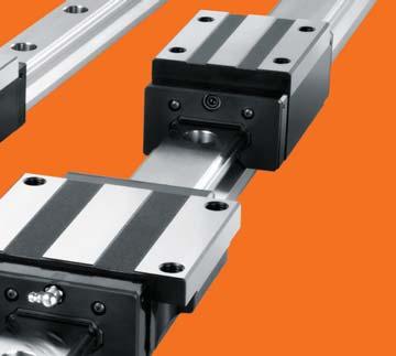
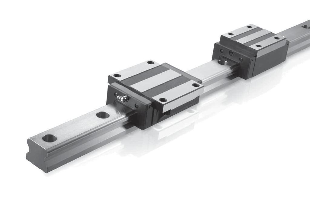
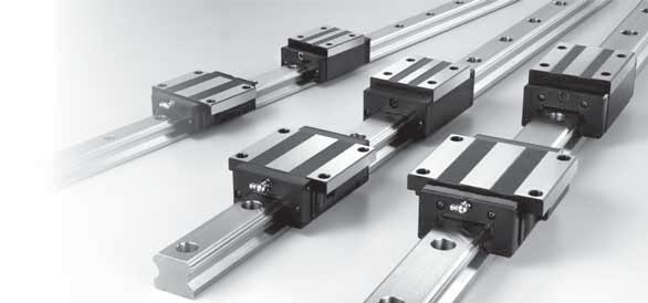
17 12 Introduction of ach Series 12.1 eavy oad Type, MSA Series C. Carriage Type A. Construction Upper Retainer Carriage nd Cap eavy oad MSA-A Type MSA- Type MSA-S Type nd Seal Rail Grease Nipple Ball 45 ower Retainer Bottom Seal 45 B. Characteristics Installed from top side of carriage with the thread length longer than MSA- type. This type offers the installation either from top or bottom side of carriage. Square type with smaller width and can be installed from top side of carriage. The trains of balls are designed to a contact angle of 45 which enables it to bear an equal load in radial, reversed radial and lateral directions. Therefore, it can be applied in any installation direction. Furthermore, MSA series can achieve a well balanced preload for increasing rigidity in four directions while keeping a low frictional resistance. This is especially suit to high precision and high rigidity required motion. The patent design of lubrication route makes the lubricant evenly distribute in each circulation loop. Therefore, the optimum lubrication can be achieved in any installation direction, and this promotes the performance in running accuracy, service life, and reliability. Ultra eavy oad igh Rigidity, Four-way qual oad The four trains of balls are allocated to a circular contact angle at 45, thus each train of balls can take up an equal rated load in all four directions. Moreover, a sufficient preload can be achieved to increase rigidity, and this makes it suitable for any kind of installation. Smooth Movement with ow Noise Self Alignment Capability The self adjustment is performed spontaneously as the design of face-to-face (DF) circular arc groove. Therefore, the installation error could be compensated even under a preload, and which results in precise and smooth linear motion. Interchangeability MSA-A Type MSA- Type MSA-S Type The simplified design of circulating system with For interchangeable type of linear guideway, the strengthened synthetic resin accessories makes the dimensional tolerances are strictly maintained movement smooth and quiet. within a reasonable range, and this has made the random matching of the same size of rails and carriages possible. Therefore, the similar preload and All dimensions are same as MSA-A except the length is longer, which makes it more rigid. All dimensions are same as MSA- except the length is longer, which makes it more rigid. All dimensions are same as MSA-S except the length is longer, which makes it more rigid. accuracy can be obtained even under the random matching condition. As a result of this advantage, the linear guideway can be stocked as standard parts, the installation and maintenance become more convenient. Moreover, this is also beneficial for shortening the delivery time. 3 eavy oad Type, MSA Series General Catalog 31
18 D. Rail Type Counter bore (R type) Tapped ole (T type) Subsidiary rail 1 2 Master rail 32. Description of Specification (1) Non-Interchangeable Type Series MSA Size 15, 2, 25, 3, 35, 45, 55, 65 Carriage type (1) eavy load A : Flange type, mounting from top : Flange type, mounting either from top or bottom S : Square type (2) Ultra heavy load A : Flange type, mounting from top : Flange type, mounting either from top or bottom S : Square type Number of carriages per rail 1, 2, 3... Dust protection option of carriage No symbol, UU, SS, ZZ, DD, KK,, RR reload FC (ight preload), F (Medium preload), F1 (eavy preload) Code of special carriage No symbol, A, B... Rail type R (Counter-bore type), T (Tapped hole type) Rail length (mm) Rail hole pitch from start side (1, see Fig.12.1) Rail hole pitch to the end side (2, see Fig.12.1) Accuracy grade N,,, S, U Code of special rail No symbol, A, B... Dust protection option of rail No symbol, /CC Number of rails per axis No symbol, II, III, IV... eavy oad Type, MSA Series MSA 25 A 2 SS F A + R 12-2 / 4 A /CC II (2) Interchangeable Type Code of Carriage Code of Rail Fig12.1 Series MSA Size 15, 2, 25, 3, 35, 45, 55, 65 Carriage type (1) eavy load A : Flange type, mounting from top : Flange type, mounting either from top or bottom S : Square type (2) Ultra heavy load A : Flange type, mounting from top : Flange type, mounting either from top or bottom S : Square type Dust protection option of carriage No symbol, UU, SS, ZZ, DD, KK,, RR reload FC (ight preload) Accuracy grade N, Code of special carriage No symbol, A, B... Series MSA Size 15, 2, 25, 3, 35, 45, 55, 65 Rail type R (Counter-bore type), T (Tapped hole type) Rail length (mm) Rail hole pitch from start side (1, see Fig.12.1) Rail hole pitch to the end side (2, see Fig.12.1) Accuracy grade N, Code of special rail No symbol, A, B... Dust protection option of rail No symbol, /CC MSA 25 A SS FC N A MSA 25 R 12-2 / 4 N A /CC General Catalog 33
19 Dimensions of MSA-A / MSA-A roduct 4-Sxl B M T 1 T F. Accuracy Grade For details, see page 26 G. reload Grade For details, see page (G) M Y. The Shoulder eight and Corner Radius for Installation For details, see page d 1 K 1 C M R I. Dimensional Tolerance of Mounting Surface For details, see page 76 J. Rail Maximum ength and Standrad Unit: mm MSA 15 MSA 2 MSA 25 MSA 3 MSA 35 MSA 45 MSA 55 MSA 65 Standard itch () Standard ( std. ) Minimum ( min. ) Max ( max.) eight xternal dimension idth ength Carriage dimension 2 2 B C S l 1 T T 1 N G K d 1 Grease Nipple MSA 15 A M G-M4 MSA 2 A MSA 2 A MSA 25 A MSA 25 A MSA 3 A MSA 3 A MSA 35 A MSA 35 A MSA 45 A MSA 45 A h d D N M M M M M G-M G-M G-M G-M G-T1/8 Unit: mm Specifications K. Tapped-hole Rail Dimensions h S Rail Model S h(mm) MSA 15 T M5 8 MSA 2 T M6 1 MSA 25 T M6 12 MSA 3 T M8 15 MSA 35 T M8 17 MSA 45 T M12 24 MSA 55 T M14 24 MSA 65 T M2 3 Rail dimension Basic load rating Static moment rating eight M M Y idth eight itch D h d Dynamic C Static C o M R Carriage 1 1 std. kn kn kg Single * Double * Single * Double* MSA 15 A MSA 2 A MSA 2 A MSA 25 A MSA 25 A MSA 3 A MSA 3 A MSA 35 A MSA 35 A MSA 45 A MSA 45 A Note: Request for size 55 and 65 MSA-A / MSA-A carriage, please refer to MSA- / MSA- carriage type. Note* : Single: Single carriage/ Double: Double carriages closely contacting with each other Rail kg/m eavy oad Type, MSA Series General Catalog 35
20 roduct Dimensions of MSA- / MSA- Dimensions of MSA-S / MSA-S roduct Specifications T1 4-Sxl T T 2 2 B S 1 S 2 4- d D N h d 1 (G) K M M Y M R 1 C Bolt Size S 1 S 2 MSA 15 M5 M4 MSA 2 M6 M5 MSA 25 M8 M6 MSA 3 M1 M8 MSA 35 M1 M8 MSA 45 M12 M1 MSA 55 M14 M12 MSA 65 M16 M14 4-Sxl T B 1 h d 4- d 1 D N (G) K 1 C M M Y M R Specifications Unit: mm Unit: mm eight xternal dimension idth ength Carriage dimension 2 2 B C S l 1 T T 1 T 2 N G K d 1 Grease Nipple MSA M G-M4 MSA 2 MSA 2 MSA 25 MSA 25 MSA 3 MSA 3 MSA 35 MSA 35 MSA 45 MSA 45 MSA 55 MSA 55 MSA 65 MSA M M M M M M M G-M G-M G-M G-M G-T 1/ G-T 1/ G-T 1/8 Rail dimension Basic load rating Static moment rating eight eight xternal dimension idth ength Carriage dimension 2 2 B C S l 1 T N G K d 1 Grease Nipple MSA 15 S M G-M4 MSA 2 S MSA 2 S MSA 25 S MSA 25 S MSA 3 S MSA 3 S MSA 35 S MSA 35 S MSA 45 S MSA 45 S MSA 55 S MSA 55 S MSA 65 S MSA 65 S M5 6 M6 8 M8 1 M8 12 M1 17 M12 18 M G-M G-M G-M G-M G-T 1/ G-T 1/ G-T 1/8 Rail dimension Basic load rating Static moment rating eight idth 1 eight 1 itch std. D h d Dynamic C kn Static C o kn M M Y Single * Double* Single * Double* M R Carriage kg Rail kg/m idth 1 eight 1 itch std. D h d Dynamic C kn Static C o kn M M Y Single * Double* Single * Double* M R Carriage kg Rail kg/m MSA MSA 2 MSA 2 MSA 25 MSA 25 MSA 3 MSA 3 MSA 35 MSA 35 MSA 45 MSA 45 MSA 55 MSA 55 MSA 65 MSA MSA 15 S MSA 2 S MSA 2 S MSA 25 S MSA 25 S MSA 3 S MSA 3 S MSA 35 S MSA 35 S MSA 45 S MSA 45 S MSA 55 S MSA 55 S MSA 65 S MSA 65 S Dimensions of MSA Note* : Single: Single carriage/ Double: Double carriages closely contacting with each other. Note* : Single: Single carriage/ Double: Double carriages closely contacting with each other. General Catalog 37
21 12.2 Compact Type, MSB Series A. Construction Upper Retainer Carriage nd Cap nd Seal C. Carriage Type Medium oad MSB-T Type MSB-TS Type Rail Grease Nipple Ball 45 ower Retainer B. Characteristics 45 Bottom Seal The trains of balls are designed to a contact angle of 45 which enables it to bear an equal load in radial, reversed radial and lateral directions. Therefore, it can be applied in any installation direction. Furthermore, MSB series can achieve a well balanced preload for increasing rigidity in four directions while keeping a low frictional resistance. This is especially suit to high precision and high rigidity required motion. The patent design of lubrication route makes the lubricant evenly distribute in each circulation loop. Therefore, the optimum lubrication can be achieved in any installation direction, and this promotes the performance in running accuracy, service life, and reliability. This type offers the installation either from top or bottom side of carriage. Square type with smaller width and can be installed from top side of carriage. Compact, Four-way qual oad Self Alignment Capability eavy oad Compact design of the carriage with the four trains of balls are allocated to a circular contact angle at 45, The self adjustment is performed spontaneously as the design of face-to-face (DF) circular arc groove. MSB- Type MSB-S Type thus each train of balls can take up an equal rated load Therefore, the installation error could be compensated in all four directions. Moreover, a sufficient preload even under a preload, and which results in precise and can be achieved to increase rigidity, and this makes it smooth linear motion. suitable for any kind of installation. Smooth Movement with ow Noise Interchangeability The simplified design of circulating system with For interchangeable type of linear guideway, the strengthened synthetic resin accessories makes the dimensional tolerances are strictly maintained movement smooth and quiet. within a reasonable range, and this has made the random matching of the same size of rails and carriages possible. Therefore, the similar preload and All dimensions are same as MSB-T except the length is longer, which makes it more rigid. All dimensions are same as MSB-TS except the length is longer, which makes it more rigid. accuracy can be obtained even under the random matching condition. As a result of this advantage, the linear guideway can be stocked as standard parts, the installation and maintenance become more convenient. Moreover, this is also beneficial for 38 Compact Type, MSB Series shortening the delivery time. General Catalog 39
22 D. Rail type Counter bore (R, U type) Tapped ole (T type) Subsidiary rail 1 2 Master rail 4. Description of Specification (1) Non-Interchangeable Type MSB 25 Series MSB Size 15, 2, 25, 3, 35 Carriage type (1) Medium load T : Flange type, mounting either from top or bottom TS : Square type (2) Ultra heavy load : Flange type, mounting either from top or bottom S : Square type Number of carriages per rail 1, 2, 3... Dust protection option of carriage No symbol, UU, SS, ZZ, DD, KK,, RR reload FC (ight preload), F (Medium preload), F1 (eavy preload) Code of special carriage No symbol, A, B... Rail type R,U (1) (Counter-bore type), T (Tapped hole type) Rail length (mm) Rail hole pitch from start side (1, see Fig.12.2) Rail hole pitch to the end side (2, see Fig.12.2) Accuracy grade N,,, S, U Code of special rail No symbol, A, B... Dust protection option of rail No symbol, /CC Number of rails per axis No symbol, II, III, IV... Notr (1) U type rail is only applicable for MSB15 with M4 mounting hole. Compact Type, MSB Series 2 SS F A + R 12-2 / 4 A /CC II (2) Interchangeable Type Code of Carriage Code of Rail Fig12.2 Series MSB Size 15, 2, 25, 3, 35 Carriage type (1) Medium load T : Flange type, mounting either from top or bottom TS : Square type (2) Ultra heavy load : Flange type, mounting either from top or bottom S : Square type Dust protection option of carriage No symbol, UU, SS, ZZ, DD, KK,, RR reload FC (ight preload) Accuracy grade N, Code of special carriage No symbol, A, B... Series MSB Size 15, 2, 25, 3, 35 Rail type R,U (1) (Counter-bore type), T (Tapped hole type) Rail length (mm) Rail hole pitch from start side (1, see Fig.12.2) Rail hole pitch to the end side (2, see Fig.12.2) Accuracy grade N, Code of special rail No symbol, A, B... Dust protection option of rail No symbol, /CC Notr (1) U type rail is only applicable for MSB15 with M4 mounting hole. MSB 25 SS FC N A MSB 25 R 12-2 / 4 N A /CC General Catalog 41
23 Dimensions of MSB-T / MSB- roduct M B S 1 T 1 T M Y F. Accuracy Grade For details, see page 26 S 2 G. reload Grade For details, see page M R. The Shoulder eight and Corner Radius for Installation For details, see page 75 I. Dimensional Tolerance of Mounting Surface For details, see page 77 J. Rail Maximum ength and Standrad 1 h 4-Ød1 N ØD (G) K MSB- 1 C 4-Sxl MSB-T 1 2-Sxl K (G) N Bolt Size S 1 S 2 MSB 15 M5 M4 MSB 2 M6 M5 MSB 25 M8 M6 MSB 3 M1 M8 Specifications Ød Unit: mm Unit: mm MSB 15 MSB 2 MSB 25 MSB 3 MSB 35 Standard itch () Standard ( std. ) Minimum ( min. ) Max ( max.) MSB 15 T MSB 15 MSB 2 T MSB 2 MSB 25 T MSB 25 MSB 3 T MSB 3 eight xternal dimension idth ength Carriage dimension 2 2 B C S l 1 T T 1 N G K d 1 Grease Nipple M5 7 M6 9 M8 1 M G-M G-M G-M G-M6 Rail dimension Basic load rating Static moment rating eight K. Tapped-hole Rail Dimensions idth 1 eight 1 itch std. D h d Dynamic C kn Static C o kn M M Y Single * Double* Single * Double* M R Carriage kg Rail kg/m MSB 15 T MSB ( ) h MSB 2 T MSB S MSB 25 T MSB 25 MSB 3 T MSB Rail Model S h(mm) MSB 15 T M5 7 Note: Rail mounting holes for M3 (6x4.5x3.5) and M4 (7.5x5.3x4.5) are available for MSB15 rail. The codes of rail type are MSB15R for M3 mounting holes, and MSB15U for M4 mounting holes. MSB 2 T M6 9 Note* : Single: Single carriage/ Double: Double carriages closely contacting with each other. MSB 25 T M6 1 MSB 3 T M8 14 MSB 35 T M Compact Type, MSB Series General Catalog 43

 M R N 6 5.5 5.5 5.1 3.3 G-M4 6 5.5 12 5.9 3.3 G-M6 8 6 12 6.3 3.")

24 roduct Dimensions of MSB-TS / MSB-S 12.3 Full Roller Type, MSR Series T B M M Y A. Construction nd Cap nd Seal Grease Nipple Carriage 2 Specifications MSB 15 TS MSB 15 S MSB 2 TS MSB 2 S MSB 25 TS MSB 25 S MSB 3 TS MSB 3 S MSB 35 S MSB 35 S eight 1 xternal dimension idth h Ød 2 4-Ød1 N ØD ength (G) K 1 C Carriage dimension 2 2 B C S l 1 T N G K d 1 Grease Nipple MSB-S Sxl M4 6 M5 7 M6 9 M8 12 M MSB-TS 1 2-Sxl K (G) M R N G-M G-M G-M G-M G-M6 Unit: mm Inner Seal Roller 45 Bottom Seal Rail 45 B. Characteristics The full roller type linear guideway, MSR series, equip with rollers instead of the ball, and therefore the MSR series can provide higher rigidity and loading than the normal type with the same size. specially suit for the requests of high accuracy, heavy load and high rigidity. Ultra eavy oad The Optimization Design of Four Direction oad MSR linear guideway through rollers have a line Through the structure stress analysis of finite element contact with carriage and rail. Relative to the general method, SMR series have four trains of rollers are type linear guideway through balls have a point designed to a contact angle of 45 and the section contact; the MSR type linear guideway can offer lower design for high rigidity. xcept for bearing heavier elastic deformation while bearing the same load. Base loads in radial, reversed radial and lateral directions, a on the rollers have the same outer diameter with balls, sufficient preload can be achieved to increase rigidity, the roller can bear the heavier load. The excellent and this makes it suitable for any kind of installation. characteristics of high rigidity and ultra heavy load can suitable for the high accuracy application that heavy load is processed even more. Rail dimension Basic load rating Static moment rating eight idth 1 eight 1 itch std. D h d Dynamic C kn Static C o kn M M Y Single * Double* Single * Double* M R Carriage kg Rail kg/m MSB 15 TS MSB 15 S MSB 2 TS MSB 2 S MSB 25 TS MSB 25 S MSB 3 TS MSB 3 S MSB 35 S MSB 35 S ( ) Note: Rail mounting holes for M3 (6x4.5x3.5) and M4 (7.5x5.3x4.5) are available for MSB15 rail. The codes of rail type are MSB15R for M3 mounting holes, and MSB15U for M4 mounting holes. Note* : Single: Single carriage/ Double: Double carriages closely contacting with each other Ultra igh Rigidity Test data of rigidity Test samples Ball type MSA3 with preload F1 Full roller type MSR3 with preload F1 Roller chain type SMR3 with preload F1 Deformation (μm) MSA3 MSR3 SMR3 5 1 Radial load Dimensions of MSB General Catalog 45
25 C. Carriage Type. Description of Specification eavy oad MSR- Type MSR-S Type Series MSR MSR 25 2 SS F A + R 12-2 / 4 A /CC II Size 25, 3, 35, 45, 55, 65 This type offers the installation either from top or bottom side of carriage. Ultra eavy oad MSR- Type Square type with smaller width and can be installed from top side of carriage. MSR-S Type Carriage type (1) eavy load : Flange type, mounting either from top or bottom S : Square type (2) Ultra heavy load : Flange type, mounting either from top or bottom S : Square type Number of carriages per rail 1, 2, 3... Dust protection option of carriage No symbol, UU, SS, ZZ, DD, KK reload F (Medium preload), F1 (eavy preload), F2 (Ultra eavy reload) Code of special carriage No symbol, A, B... Rail type R (Counter bore type), T (Tapped hole type) Rail length (mm) Rail hole pitch from start side (1 see Fig12.3) Rail hole pitch to the end side (2 see Fig12.3) Accuracy grade,, S, U Code of special rail No symbol, A, B... Dust protection option of rail No symbol, /CC, /MC... Number of rails per axis No symbol, II, III, IV... All dimensions are same as MSR- except the length is longer, which makes it more rigid. All dimensions are same as MSR-S except the length is longer, which makes it more rigid. D. Rail Type Subsidiary rail Counter bore (R type) Tapped ole (T type) 1 2 Master rail Fig Full Roller Type, MSR Series General Catalog 47
26 Dimensions of MSR- / MSR- roduct M Y F. Accuracy Grade For details, see page 26 M R M G. reload Grade For details, see page 29. The Shoulder eight and Corner Radius for Installation For details, see page 76 I. Dimensional Tolerance of Mounting Surface For details, see page 77 J. Rail Maximum ength and Standrad 1 ØD h Ød N (G) 1 6-S K C 2 C 1 4-G1 T2 T T3 T 1 B S 1 S 2 Bolt Size S 1 S 2 MSR 25 M8 M6 MSR 3 M1 M8 MSR 35 M1 M8 MSR 45 M12 M1 MSR 55 M14 M12 MSR 65 M16 M14 Specifications K. Tapped-hole Rail Dimensions Unit: mm MSR 25 MSR 3 MSR 35 MSR 45 MSR 55 MSR 65 Standard itch () Standard ( std. ) Minimum ( min. ) Max ( max.) eight MSR 25 MSR 25 MSR 3 MSR 3 MSR 35 MSR 35 MSR 45 MSR 45 MSR 55 MSR 55 xternal dimension idth ength Carriage dimension 2 2 B C C 2 S 1 T T 1 T 2 T 3 N G K e 1 d 1 Grease Nipple M M M M M M6 G-M M6 G-M M6 G-M M6 G-T 1/ M6 G-T 1/8 MSR M M6 G-T 1/8 Rail dimension Basic load rating Static moment rating eight Uni:t mm h S MSR 25 MSR 25 MSR 3 MSR 3 idth 1 eight 1 itch std. D h d Dynamic C kn Static C o kn M M Y Single * Double* Single * Double* M R Carriage kg Rail kg/m MSR 35 MSR Rail Model S h(mm) MSR 25 T M6 12 MSR 3 T M8 15 MSR 35 T M8 17 MSR 45 T M12 24 MSR 45 MSR 45 MSR 55 MSR MSR Note* : Single: Single carriage/ Double: Double carriages closely contacting with each other MSR 55 T M14 24 MSR 65 T M Full Roller Type, MSR Series General Catalog 49
27 roduct Dimensions of MSR-S / MSR-S M Y 12.4 Miniature Type, MSC Stainless Steel Series A. Construction M R M Carriage Specifications MSR 25 S MSR 25 S MSR 3 S MSR 3 S MSR 35 S MSR 35 S MSR 45 S MSR 45 S MSR 55 S MSR 55 S eight Rail dimension idth ength xternal dimension 2 2 B C S l 1 T N G K e 1 G 1 Grease Nipple M6 1.5 M8 12 M8 14 M1 19 M M6 G-M M6 G-M M6 G-M M6 G-T 1/ M6 G-T 1/8 MSR 65 S M M6 G-T 1/8 MSR 25 S MSR 25 S MSR 3 S MSR 3 S MSR 35 S MSR 35 S MSR 45 S MSR 45 S MSR 55 S MSR 55 S idth 1 l T eight 1 Rail dimension Basic load rating Static moment rating eight itch B std. D h d S 1 h Ød Dynamic C kn ØD Static C o kn M M Y Single * Double* Single * Double* M R Carriage kg MSR 65 S Note* : Single: Single carriage/ Double: Double carriages closely contacting with each other. N (G) e 1 6-Sxl C K 1 4-G Unit: mm Rail kg/m nd Cap nd Seal Rail Ball Retainer 45 Bottom Seal 45 B. Characteristics MSC stainless steel series are applied two rows with Gothic-arch groove and designed to contact angle of 45 which enables it to bear an equal load in radial, reversed radial and lateral directions. Furthermore, ultra compact and low friction resistance design is suit to compact equipment. The lubrication route makes the lubricant evenly distribute in each circulation loop. Therefore,the optimum lubrication can be achieved in any installation direction, and this promotes the performance in running accuracy, service life, and reliability. Four-way qual oad Smooth Movement with ow Noise The two trains of balls are allocated to a Gothic-arch The simplified design of circulating system with groove contact angle at 45, thus each train of balls can strengthened synthetic resin accessories makes the takeup an equal rated load in all four directions. movement smooth and quiet. Ultra Compact Interchangeability The ultra compact design is suit to the compact For interchangeable type of linear guideway, the application with limited in space. dimensional tolerances are strictly maintained within a reasonable range, and this has made the Ball Retainer random matching of the same size of rails and carriages possible. Therefore, the similar preload and Design with ball retainer can prevent ball form accuracy can be obtained even under the random dropping. matching condition. As a result of this advantage, the linear guideway can be stocked as standard parts, the installation and maintenance become more convenient. Moreover, this is also beneficial for shortening the delivery time. 5 Dimensions of MSR General Catalog 51
28 C. Description of Specification (1) Non-interchangeable Type Series MSC Size 7, 9, 12, 15 Carriage type M: Standard type (Stainless) M: eavy load type (Stainless) Number of carriages per rail 1, 2, 3... Dust protection option of carriage, RR reload FC (ight preload), F (Medium preload) Code of special carriage No symbol, A, B... Rail type R (Counter bore type) Rail length (mm) Rail hole pitch from start side (1, see Fig.12.4) Rail hole pitch to the end side (2, see Fig.12.4) Accuracy grade N,, Stainless steel Code of special rail No symbol, A, B... Number of rails per axis No symbol, II, III, IV... Subsidiary rail MSC 7 M 2 F A + R /7.5 M A II 1 2 (2) Interchangeable Type Code of Carriage Code of Rail Series MSC Size 7, 9, 12, 15 Carriage type M: Standard type (Stainless) M: eavy load type (Stainless) Dust protection option of carriage, RR reload FC (ight preload) Accuracy grade N, Code of special carriage No symbol, A, B... Series MSC Size 7, 9, 12, 15 Rail type R (Counter bore type) Rail length (mm) Rail hole pitch from start side (1, see Fig.12.4) Rail hole pitch to the end side (2, see Fig.12.4) Accuracy grade N, Stainless steel Code of special rail No symbol, A, B... MSC 7 M FC N A MSC 7 R /7.5 N M A Master rail Fig Miniature Type, MSC Stainless Steel Series General Catalog 53
29 Dimensions of MSC-M / MSC-M roduct F. Accuracy Grade For details, see page 28 G. reload Grade For details, see page 29 4-Sx l T B G M M Y M R. The Shoulder eight and Corner Radius for Installation For details, see page 76 I. Dimensional Tolerance of Mounting Surface For details, see page 78 J. Rail Maximum ength and Standrad 2 1 h 1 d D 1 C Specifications Unit: mm Unit: mm MSC 7 MSC 9 MSC 12 MSC 15 MSC 7 M MSC 7 M MSC 9 M MSC 9 M eight idth xternal dimension ength Carriage dimension 2 2 B C S l 1 T G M2 2.5 M Ø Ø1 Standard itch () Standard ( std. ) Max ( max.) MSC 12 M MSC 12 M MSC 15 M MSC 15 M M3 3.6 M Ø1.5 7 G-M3 Rail dimension Basic load rating Static moment rating eight idth 1 eight 1 itch std. D h d Dynamic C kn Static C o kn M N-m M Y N-m Single * Double * Single * Double * M R N-m Carriage g Rail kg/m MSC 7 M MSC 7 M MSC 9 M MSC 9 M MSC 12 M MSC 12 M MSC 15 M MSC 15 M Note* : Single: Single carriage/ Double: Double carriages closely contacting with each other. 54 Miniature Type, MSC Stainless Steel Series General Catalog 55
30 12.5 Ball Chain Type, SM Series A. Construction C. Carriage Type Carriage eavy oad nd Cap nd Seal Grease Nipple SM-A Type SM-B Type Ball Chain Inner Seal Ball Bottom Seal 45 Rail 45 B. Characteristics The ball chain type linear guideway, SM series, equip with the patent of ball chain design can make the movement smooth and stability, especially suit for the requests of high speed, high accuracy. The Optimization Design of Direction oad Self Alignment Capability This type offers the installation either from top or bottom side of carriage. All dimensions are same as SM-A except the mounting hole dimensions of carriage are different and the height is lower, which do not change the basic loading rating. Through the structure stress analysis, SM series have The self adjustment is performed spontaneously as the four trains of balls are designed to a circular contact design of face-face (DF) circular arc groove. Therefore, angle of 45 and the section design for high rigidity. the installation error could be compensated even xcept for bearing heavier loads in radial, reversed under a preload, and which results in precise and radial and lateral directions, a sufficient preload can be smooth linear motion. achieved to increase rigidity, and this makes it suitable for any kind of installation. SM-SA Type SM-SB / SM-SV Type Ball Chain Design, Smooth Movement ow Noise, Good ubricant ffect The concise and smooth design of circulating system The ball chain design avoids interference between with strengthened synthetic resin accessories and balls, lowers the operating noise, and can keep the cooperating with the ball chain, these can avoid lubricant between the balls and ball chain effectively. interference between balls and make the balls more Moreover, improve the movement smooth and stability during passing in and out the load district. service life of the whole, can meet high accuracy, high Besides, the ball chain can keep the ball move in a line reliability and smooth and stability. and improve the movement most smooth substantially. Kgf Ball chain type, SM series Standard type, MSB series Noise evel (dba) SM3 MSB3 9 dba Square type with smaller width and can be installed from top side of carriage. All dimensions are same as SM-SA except the mounting hole dimensions of carriage are different and the height is lower, which do not change the basic loading rating mm Rolling resistance test Speed (m/min) Noise level comparison test 56 Ball Chain Type, SM Series General Catalog 57
31 Ultra eavy oad. Description of Specification SM-A Type SM-B Type (1) Non-interchangeable Type SM 25 A 2 SS F A +R 1-2 /2 A /CC II Series SM Size 15, 2, 25, 3, 35, 45 All dimensions are same as SM-A except the length is longer, which makes it more rigid. SM-SA Type All dimensions are same as SM-SA except the length is longer, which makes it more rigid. D. Rail Type Counter bore(r type) All dimensions are same as SM-B except the length is longer, which makes it more rigid. SM-SB / SM-SV Type All dimensions are same as SM-SB and SM- SV except the length is longer, which makes it more rigid. Tapped-ole(T type) Carriage type (1) eavy load A Flange type, mounting either from top or bottom B Compact flange type, mounting either from top or bottom SA Square type SB/SV Compact square type (2) Ultra heavy load A Flange type, mounting either from top or bottom B Compact flange type, mounting either from top or bottom SA Square type SB/SV Compact square type Number of carriages per rail 1, 2, 3... Dust protection option of carriage No symbol, UU, SS, ZZ, DD, KK reload FC (ight reload), F (Medium preload), F1 (eavy preload) Code of special carriage No symbol, A, B... Rail type R (Counter-bore type), T (Tapped hole type) Rail length (mm) Rail hole pitch from start side (1, see Fig.12.5) Rail hole pitch to the end side (2, see Fig.12.5) Accuracy grade N,,, S, U Code of special rail No symbol, A, B... Dust protection option of rail No symbol, /CC, /MC... Number of rails per axis No symbol, II, III, IV... Subsidiary rail 1 2 Master rail 58 Ball Chain Type, SM Series Fig 12.5 General Catalog 59
32 (2) Interchangeable Type Code of Carriage Series SM Size 15, 2, 25, 3, 35, 45 Carriage type (1) eavy load A Flange type, mounting either from top or bottom B Compact flange type, mounting either from top or bottom SA Square type SB/SV Compact square type (2) Ultra heavy load A Flange type, mounting either from top or bottom B Compact flange type, mounting either from top or bottom SA Square type SB/SV Compact square type Number of carriages per rail 1, 2, 3... Dust protection option of carriage No symbol, UU, SS, ZZ, DD, KK reload FC (ight reload) Accuracy grade N, Code of special carriage No symbol, A, B... SM 25 A 2 SS FC A F. Accuracy Grade For details, see page 26 G. reload Grade For details, see page 29. The Shoulder eight and Corner Radius for Installation For details, see page 76 I. Dimensional Tolerance of Mounting Surface For details, see page 77 J. Rail Maximum ength and Standrad Unit: mm SM 15 SM 2 SM 25 SM 3 SM 45 SM 45 Standard itch () Standard ( std. ) Minimum ( min. ) Max ( max.) K. Tapped-hole Rail Dimensions Code of Rail Series SM SM 25 R 1-2 /2 A /CC h Size 15, 2, 25, 3, 35, 45 S Rail type R (Counter-bore type), T (Tapped hole type) Rail length (mm) Rail hole pitch from start side (1, see Fig.12.5) Rail hole pitch to the end side (2, see Fig.12.5) Accuracy grade N, Code of special rail No symbol, A, B... Dust protection option of rail No symbol, /CC, /MC... Rail Model S h(mm) SM 15 T M5 8 SM 2 T M6 1 SM 25 T M6 12 SM 3 T M8 15 SM 35 T M8 17 SM 45 T M Ball Chain Type, SM Series General Catalog 61
33 roduct Dimensions of SM-A / SM-A Dimensions of SM-B / SM-B roduct M Y M Y M R M M R M Specifications 1 h 4-S l D N d e 1 (G) K C 1 4-G 1 T 1 T 2 2 B 1 S1 S2 Bolt Size S 1 S 2 SM 15 M5 M4 SM 2 M6 M5 SM 25 M8 M6 SM 3 M1 M8 SM 35 M1 M8 SM 45 M12 M1 1 h 4-S l D N d e1 (G) K C 1 4-G1 T 1 T 2 2 B 1 S1 S2 Bolt Size S 1 S 2 SM 15 M5 M4 SM 2 M6 M5 SM 25 M8 M6 Specifications SM 15 A SM 15 A SM 2 A SM 2 A SM 25 A SM 25 A SM 3 A SM 3 A SM 35 A SM 35 A SM 45 A SM 45 A SM 15 A SM 15 A SM 2 A SM 2 A SM 25 A SM 25 A SM 3 A SM 3 A SM 35 A SM 35 A SM 45 A SM 45 A eight xternal dimension idth idth 1 eight 1 ength Carriage dimension 2 2 B C S l 1 T T 1 N G K e 1 G 1 Grease Nipple M M M M M M M4 G-M M4 G-M M4 G-M M6 G-M M6 G-M M6 G T 1/8 Rail dimension Basic load rating Static moment rating eight itch std. D h d Dynamic C kn Static C o kn M M Y Single * Double* Single * Double* M R Carriage kg Unit: mm Rail kg/m SM 15 B SM 15 B SM 2 B SM 2 B SM 25 B SM 25 B SM 15 B SM 15 B SM 2 B SM 2 B SM 25 B SM 25 B eight xternal dimension idth idth 1 eight 1 ength Carriage dimension 2 2 B C S l 1 T T 1 N G K e 1 G 1 Grease Nipple M5 8 M6 8 M M4 G-M M4 G-M M4 G-M6 Rail dimension Basic load rating Static moment rating eight itch std. D h d Dynamic C kn Static C o kn Note* : Single: Single carriage/ Double: Double carriages closely contacting with each other. M M Y Single * Double* Single * Double* M R Carriage kg Unit: mm Rail kg/m Note* : Single: Single carriage/ Double: Double carriages closely contacting with each other. 62 Dimensions of SM General Catalog 63
34 4-S l e1 C (G) K 1 B Dimensions of SM-SA / SM-SA M Y M R M (G) 2 T h D d N 4-G1 B Unit: mm roduct Dimensions of SM-SB / SM-SB SM-SV / SM-SV roduct M Y M R M 4-S l e1 C Specifications 2 T h D d N K 1 4-G1 Specifications Unit: mm eight xternal dimension idth ength Carriage dimension 2 2 B C S l 1 T N G K e 1 G 1 Grease Nipple eight xternal dimension idth ength Carriage dimension 2 2 B C S l 1 T N G K e 1 G 1 Grease Nipple SM 15 SA SM 15 SA M M4 G-M4 SM 15 SB SM 15 SB M M4 G-M4 SM 2 SA SM 2 SA M M4 G-M6 SM 2 SB SM 2 SB M M4 G-M6 SM 25 SA SM 25 SA M M4 G-M6 SM 25 SB SM 25 SB M M4 G-M6 SM 3 SA SM 3 SA M M6 G-M6 SM 25 SV SM 25 SV M M4 G-M6 SM 35 SA SM 35 SA M M6 G-M6 SM 3 SB SM 3 SB M M6 G-M6 SM 45 SA SM 45 SA M M6 G T 1/8 SM 35 SB SM 35 SB M M6 G-M6 Rail dimension Basic load rating Static moment rating eight SM 45 SB SM 45 SB M M6 G T 1/8 SM 15 SA SM 15 SA idth 1 eight 1 itch std. D h d Dynamic C kn Static C o kn M M Y Single * Double* Single * Double* M R Carriage kg Rail kg/m 1.4 idth 1 eight 1 Rail dimension Basic load rating Static moment rating eight itch std. D h d Dynamic C kn Static C o kn M M Y Single * Double* Single * Double* M R Carriage kg Rail kg/m SM 2 SA SM 2 SA SM 15 SB SM 15 SB SM 25 SA SM 25 SA SM 2 SB SM 2 SB SM 3 SA SM 3 SA SM 25 SB SM 25 SB SM 35 SA SM 35 SA SM 25 SV SM 25 SV SM 45 SA SM 45 SA SM 3 SB SM 3 SB Note* : Single: Single carriage/ Double: Double carriages closely contacting with each other. SM 35 SB SM 35 SB SM 45 SB SM 45 SB Dimensions of SM Note* : Single: Single carriage/ Double: Double carriages closely contacting with each other. General Catalog 65


35 12.6 Roller Chain Type, SMR Series A. Construction Carriage nd Cap nd Seal Grease Nipple Inner Seal Roller Chain 45 Roller Bottom Seal Rail 45 B. Characteristics The roller chain type linear guideway, SMR series, equip with rollers instead of the ball, and therefore the SMR series can provide higher rigidity and loading than the normal type with the same size. Besides, the patent of roller chain design can make the movement smooth and stability, especially suit for the requests of high accuracy, heavy load and high rigidity. Ultra eavy oad The Optimization Design of Four Direction oad SMR linear guideway through rollers have a line Through the structure stress analysis of finite element contact with carriage and rail. Relative to the general method, SMR series have four trains of rollers are type linear guideway through balls have a point designed to a contact angle of 45 and the section contact; the SMR type linear guideway can offer lower design for high rigidity. xcept for bearing heavier elastic deformation while bearing the same load. Base loads in radial, reversed radial and lateral directions, a on the rollers have the same outer diameter with balls, sufficient preload can be achieved to increase rigidity, the roller can bear the heavier load. The excellent and this makes it suitable for any kind of installation. characteristics of high rigidity and ultra heavy load can suitable for the high accuracy application that heavy load is processed even more. Roller Chain Design, Smooth Movement The concise and smooth design of circulating system with strengthened synthetic resin accessories and cooperating with the roller chain, these can avoid interference between rollers and make the rollers more stability during passing in and out the load district. Besides, the roller chain can keep the roller move in a line and improve the movement most smooth substantially. ow Noise, Good ubricant ffect The roller chain design avoids interference between rollers, lowers the operating noise, and can keep the lubricant between the rollers and roller chain effectively. Moreover, improve the movement smooth and service life of the whole, can meet high accuracy, high reliability and smooth and stability. C. Carriage Type eavy oad SMR- Type SMR-S Type This type offers the installation either from top or bottom side of carriage. Square type with smaller width and can be installed from top side of carriage. Ultra eavy oad Ultra igh Rigidity Test data of rigidity SMR- Type SMR-S Type Test samples Ball type MSA3 with preload F1 Full roller type MSR3 with preload F1 Roller chain type SMR3 with preload F1 Deformation (μm) MSA3 MSR3 SMR3 5 1 Radial load 15 2 All dimensions are same as SMR- except the length is longer, which makes it more rigid. All dimensions are same as SMR-S except the length is longer, which makes it more rigid. 66 Roller Chain Type, SMR Series General Catalog 67
The Classification Chart of PMI Linear Guideways
 1 The Characteristics of MI s The Classification Chart of MI s 2 (1) igh positioning accuracy, high repeatability The MI linear guideway is a design of rolling motion with a low friction coefficient, and
Ballscrews / Linear Guideway General Catalog
 Ballscrews / inear Guideway General Catalog inear Guideway 2 Introduction of ach Series 2. eavy oad Type, MSA Series A. Construction Upper Retainer Carriage nd Seal nd Cap Rail Grease Nipple Ball 45 ower
(1) High positioning accuracy, high repeatability. (2) Low frictional resistance, high precision maintained for long period
 High positioning accuracy, high repeatability. (2) Low frictional resistance, high precision maintained for long period") Linear Guideway 1 The Characteristics of PMI Linear Guideways (1) igh positioning accuracy, high repeatability The PMI linear guideway is a design of rolling motion with a low friction coeffcient, and
Linear Guideway 1 The Characteristics of PMI Linear Guideways (1) igh positioning accuracy, high repeatability The PMI linear guideway is a design of rolling motion with a low friction coeffcient, and
Introduction of Each Series
 12 Introduction of Each Series 12.1 eavy Load Type, MSA Series A. Construction LINEAR GUIDEWAY Upper Retainer Carriage End Cap End Seal Grease Nipple Ball Lower Retainer Rail 45 eavy Load Type, MSA Series
The Characteristics of PMI Linear Guideways
 Linear Guideway 1 The Characteristics of PMI Linear Guideways (1) High positioning accuracy, high repeatability The PMI linear guideway is a design of rolling motion with a low friction coeffcient, and
Precise Stable Durability High Rigidity. Meet the Multi-Demand of Accuracy and Efficiency
 Precise Stable Durability High Rigidity Meet the Multi-Demand of Accuracy and Efficiency Linear Guideway B1-1 The Characteristics of PMI Linear Guideways High positioning accuracy, high repeatability
Linear Guideway. Forniture per l Industria Gelmini S.r.l.
 Linear Guideway Forniture per l Industria Gelmini S.r.l. Sede Via Cerati, 3/A 43126 Parma Tel. 0521.993844 Fax 0521.291688 Filiale Via Tiziano, 11 46040 Z.I. Guidizzolo (MN) Tel. 0376.847123 Fax 0376.840319
12.3 Full Roller Type, MSR Series
 12.3 Full Roller Type, MSR Series A. Construction Carriage End Seal Grease Nipple End Cap Inner Seal Roller Bottom Seal 45 Rail 45 B. Characteristics The full roller type linear guideway, MSR series, equip
12.5 Ball Chain Type, SME Series
 12.5 Ball Chain Type, SME Series A. Construction Carriage End Cap End Seal Grease Nipple Inner Seal Ball Bottom Seal Ball Chain 45 Rail 45 B. Characteristics The ball chain type linear guideway, SME series,
12.4 Miniature Type, MSC MSD Stainless Steel Series
 12.4 Miniature Type, MSC MSD Stainless Steel Series A. Construction Carriage End Cap MSC Standard Type End Seal Rail MSD Wide Type Ball Retainer Bottom Seal 45 45 B. Characteristics MSC st ows with Gothic-arch
Miniature Linear Guideway MSC Stainless Steel Series
 Supreme Performance of High Precision 1 Construction Carriage End Cap End Seal Rail Ball Retainer Bottom Seal 4 4 2 Characteristics MSC stainless steel series are applied two rows with Gothicarch groove
Linear Guideways HG Series
 18 G99TE1-67 Linear Guideways 2-1 - Heavy Load Ball Type Linear Guideway HG series linear guideways are designed with load capacity and rigidity higher than other similar products with circular-arc groove
2-9 RG Series High Rigidity Roller Type Linear Guideway
 G99TE17-136 2-9 High Rigidity Roller Type Linear Guideway 2-9-1 Advantages and features The new RG series from Hiwin features a roller as the rolling element instead of steel balls. The roller series offers
506E. LM Guide Actuator General Catalog
 LM Guide Actuator General Catalog A LM Guide Actuator General Catalog A Product Descriptions 506E Caged Ball LM Guide Actuator Model SKR.. A2-4 Structure and Features... A2-4 Caged Ball Technology... A2-6
Inner block. Grease nipple. Fig.1 Structure of LM Guide Actuator Model KR
 LM Guide ctuator Model LM Guide + all Screw = Integral-structure ctuator Stopper Housing all screw Inner block Grease nipple Outer rail earing (supported side) Housing Stopper Double-row ball circuit earing
Precision Linear Pack
 Precision Linear Pack General Catalog A Technical Descriptions of the Products B Product Specifications (Separate) Features... Features of the Precision Linear Pack... Structure and features... Rated Load
Ball. Ball cage. Fig.1 Structure of Caged Ball LM Guide Actuator Model SKR
 Caged all LM Guide Actuator Model Inner block all screw shaft Grease nipple Outer rail all cage all Structure and Features Fig.1 Structure of Caged all LM Guide Actuator Model Caged all LM Guide Actuator
2-1 HG Series - Heavy Load Ball Type Linear Guideway
 2 G99TE15-114 Linear Guideways 2-1 - Heavy Load Ball Type Linear Guideway HG series linear guideways are designed with load capacity and rigidity higher than other similar products with circular-arc groove
Ball Rail Systems RE / The Drive & Control Company
 Ball Rail Systems RE 82 202/2002-12 The Drive & Control Company Rexroth Linear Motion Technology Ball Rail Systems Roller Rail Systems Standard Ball Rail Systems Super Ball Rail Systems Ball Rail Systems
HSR. LM Guide Global Standard Size Model HSR. Point of Selection. Point of Design. Options. Model No. Precautions on Use
 LM Guide Global Standard Size Model Retainer plate Endplate End seal Grease nipple Ball Retainer plate Inner seal (Optional) Side seal LM rail Cross section 45 45 Point of Selection A Point of Design Options
Linear Guideway. Technical Information.
 Linear Guideway Technical Information www.hiwin.com.tw Linear Guideways Technical Information Index Preface...1 1. General Information...1 1-1 Advantages and features of Linear Guideway...1 1-2 The principles
SHS. Caged Ball LM Guide Global Standard Size Model SHS. Point of Selection. Point of Design. Options. Model No. Precautions on Use
 Caged Ball LM Guide Global Standard Size Model LM block LM rail Endplate End seal 45 Ball Ball cage Cross section 45 * For the Ball Cage, see. Point of Selection Point of Design Options Model No. Precautions
Features of the LM Guide
 Features of the Functions Required for Linear Guide Surface Large permissible load Highly rigid in all directions High positioning repeatability Running accuracy can be obtained easily High accuracy can
1 of 19. Asia Automation Parts Supply (PG) Sdn. Bhd. Flange Unit (Oval) Pillow Block
 Sdn. Bhd. Flange Unit (Oval) Pillow Block") Asia Automation Parts Supply (PG) Sdn. Bhd. Flange Unit (Oval) Pillow Block YAMADA Spherical Plain Radial Bearings with Fitting Crack and Fitting Groove YAMADA Thrust Ball Bearing Series 51100 & 51200
Asia Automation Parts Supply (PG) Sdn. Bhd. Flange Unit (Oval) Pillow Block YAMADA Spherical Plain Radial Bearings with Fitting Crack and Fitting Groove YAMADA Thrust Ball Bearing Series 51100 & 51200
Miniature LM Guide RSR and RSR-W
 iniature Guide RSR and RSR End plate block rail End seal Ball Greace nipple ig. 1 onstruction of odel RSRV onstruction and eatures Balls roll in two rows of precisionground raceways on an rail and an block.
Features of the LM Guide
 Features of the Functions Required for Linear Guide Surface Large permissible load Highly rigid in all directions High positioning repeatability Running accuracy can be obtained easily High accuracy can
G10TE HG Linear Guideway
 G10TE01-0310 I HG Linear Guideway Preface... 1 1... 1 1-1... 1 1-2... 2 1-3... 3 1-3-1 1-3-2 1-4... 4 1-4-1 1-4-2 1-4-3 1-4-4 1-4-5 1-5... 6 1-5-1 1-5-2 1-5-3 1-5-4 1-6... 9 1-7... 9 1-7-1 1-7-2 1-8...
Linear Guideways QH Series
 G99TE17-136 2-6 Quiet Linear Guideway, with SynchMotion TM Technology The development of HIWIN-QH linear guideway is based on a four-row circular-arc contact. The HIWIN-QH series linear guideway with SynchMotion
LM Guide Actuator KR. For details, visit THK at CATALOG No E. Product information is updated regularly on the THK website.
 LM Guide Actuator KR For details, visit THK at www.thk.com Product information is updated regularly on the THK website. CATALOG No.209-10E Integrated LM Guide and all Screw High-rigidity / High-precision
Linear Bushing General Catalog
 General Catalog A Technical Descriptions of the Products B Product Specifications (Separate) Features and Types... Features of the... Structure and features... Dedicated Shafts for Model LM... Standard
Studying the Positioning Accuracy
 Ball Screw Studying the Positioning Accuracy Causes of Error in the Positioning Accuracy Point of Selection Studying the Positioning Accuracy The causes of error in the positioning accuracy include the
...components in motion. Miniature Linear Guideways
 ...components in motion Miniature Linear Introduction Miniature linear guideway systems are widely used throughout industry for precise, compact applications. Precise and Stainless The gothic arch shape
LM Guide Radial Type Model SR
 LM Guide Radial Type Model Endplate LM block Grease nipple End seal LM rail 90 Ball Retainer plate Side seal (Optional) Cross section 30 Point of Selection A Point of Design Options Model No. Precautions
RSR. LM Guide Miniature Types Model RSR. Point of Selection. Point of Design. Options. Model No. Precautions on Use
 LM Guide Miniature Types Model Endplate LM block End seal LM rail Ball Grease nipple Cross section Point of Selection A Point of Design Options Model No. Precautions on Use Accessories for Lubrication
HSR-M1. LM Guide High Temperature Type Model HSR-M1. Point of Selection. Point of Design. Options. Model No. Precautions on Use
 LM Guide High Temperature Type Model Endplate SUS304 End seal (High temperature rubber material) LM THK-EX50 Ball SUS440C Side seal (High temperature rubber material) LM rail THK-EX50 Cross section 45
Caged Roller LM Guide
 Caged Roller LM Guide SRG/SRN Ultra-high Rigidity Long-term Maintenance-free Operation Smooth Motion Wide Array of Options For details, visit THK at www.thk.com Product information is updated regularly
Caged Ball LM Guide Actuator SKR
 Caged Ball LM Guide Actuator SKR For details, visit THK at www.thk.com Product information is updated regularly on the THK website. CATALOG No.309-11E Integrated LM Guide and Ball Screw High-rigidity /
Cross Roller Guide/Ball Guide General Catalog
 General Catalog A Product Descriptions Features and Types... A7-2 Features of the.. A7-2 Structure and Features... A7-2 Types of the.. A7-3 Types and Features... A7-3 Point of Selection... A7-4 Rated Load
Profi le rail guides LLR
 Profi le rail guides LLR Content The SKF brand now stands for more than ever before, and means more to you as a valued customer. While SKF maintains its leadership as the hallmark of quality bearings throughout
SSR. Caged Ball LM Guide Radial Type Model SSR. Point of Selection. Point of Design. Options. Model No. Precautions on Use
 Caged Ball LM Guide Radial Type Model Endplate LM block End seal LM 90 30 Ball Ball cage Cross section * For the Ball Cage, see A. Point of Selection A Point of Design Options Precautions on Use Accessories
Crossed Roller Ways. Description of each series and Table of dimensions. Anti-Creep Cage Crossed Roller Way
 Crossed Roller Ways Description of each series and Table of dimensions Crossed Roller Way Page - to -7 Anti-Creep Cage Crossed Roller Way Page - to - Crossed Roller Way Unit Page - to - In the table of
LM Guide HCR/HMG. R Guide / Straight-Curved Guide Achieving a Simplified Mechanism. For details, visit THK at CATALOG No.
 LM Guide HCR/HMG R Guide / Straight-Curved Guide Achieving a Simplified Mechanism For details, visit THK at www.thk.com Product information is updated regularly on the THK website., CATALOG No.306-8E HCR
Linear Bushing. General Catalog A-523
 Linear Bushing General Catalog A Technical Descriptions of the Products B Product Specifications (Separate) Features and Types... Features of the Linear Bushing... Structure and features... Dedicated Shafts
SRS. Caged Ball LM Guide Miniature Type Model SRS. Point of Selection. Point of Design. Options. Model No. Precautions on Use
 Caged Ball M Guide Miniature Type Model M rail Endplate End seal M block Compact type Model -M Ball Side seal Ball cage Wide type Model -WM * or the ball cage, see A. Point of Selection A Point of Design
BALLSCREW INSPECTION CERTIFICATE Inspected by HEWLETT PACKARD Laser Measuring System
 1 (1) High reliability Features of PMI Ballscrews PMI has accumulated many years experience in production managing. It covers the whole production sequence, from receiving the order, designing, material
SRG. Caged Roller LM Guide Ultra-high Rigidity Type Model SRG. Point of Selection. Point of Design. Options. Model No. Precautions on Use
 Caged Roller LM Guide Ultra-high Rigidity Type Model LM block LM rail End seal Endplate 45 45 Caged roller Roller 45 Cross section 45 * or the caged roller, see. Point of Selection A Point of Design Options
Linear Guideway. Technical Information.
 Linear Guideway Technical Information www.hiwin.com.tw Linear Guideways Technical Information Index Preface...1 1. General Information...1 1-1 Advantages and features of Linear Guideway...1 1-2 The principles
SVR/SVS. Caged Ball LM Guide Ultra-heavy Load Type for Machine Tools Model SVR/SVS. Point of Selection. Point of Design. Options. Model No.
 Caged Ball Guide Ultra-heavy Load Type for Machine Tools Model Protector 90 rail Ball cage Radial type model SVR Cross section 40 50 Ball * For the Ball Cage, see A. 4-Way Type Model SVS Cross section
Courtesy of CMA/Flodyne/Hydradyne Motion Control Hydraulic Pneumatic Electrical Mechanical (800)
") 01_1 Miniature st Headline_36 Ball Rail pt/14.4 Systems mm second line 2 Linear Motion and Assembly Technologies Miniature Ball Rail Systems Ball Rail Systems Roller Rail Systems Linear Bushings and Shafts
01_1 Miniature st Headline_36 Ball Rail pt/14.4 Systems mm second line 2 Linear Motion and Assembly Technologies Miniature Ball Rail Systems Ball Rail Systems Roller Rail Systems Linear Bushings and Shafts
series Linear guideways CG-serie 3.3 CG series
 series CG-serie 3.3 CG series 3.3.1 Properties of the linear guideways, series CG The HIWIN linear guideways of the CG series with O-arrangement of the ball tracks guarantee high torque loading capacity,
Linear Guideways MG Series
 52 2-3 - Miniature Linear Guideway 2-3-1 Features of MGN Series 1. Tiny and light weight, suitable for miniature equipment. 2. All materials in special grade of stainless steel for anti-corrosion size
Guide plate. Fig. 1 Construction of Slide Pack Type FBW-RUU
 A Slide Pack Slide Pack Type FBW Japanese patent No. 1696446 Overseas patent resistered in the U.S. Mounting plate Ball Slide rail Seal Guide plate Stopper Fig. 1 Construction of Slide Pack Type FBW-RUU
4mm(H)x8mm(W) Micro LM Guides
x8mm(W) Micro LM Guides") 4mm(H)x8mm(W) Micro LM Guides US, EPC, Patent Pending CATALOG No.293E Micro LM Guides RSR3M/3N The micro size allows space-saving design. Can be used in various fields of industry including micro machines
4mm(H)x8mm(W) Micro LM Guides US, EPC, Patent Pending CATALOG No.293E Micro LM Guides RSR3M/3N The micro size allows space-saving design. Can be used in various fields of industry including micro machines
A SH Series. SH Series. 2. Ball slide shape
 S Series -5-1.2 S Series 1. eatures (1) ower noise and gentler tone Incorporating a retaining piece and optimizing te circulation pat enables steel ball circulation stability and te prevention of ball
RSR-M1. LM Guide High Temperature Type Model RSR-M1. Point of Selection. Point of Design. Options. Model No. Precautions on Use
 LM Guide High Temperature Type Model Endplate SUS34 LM block THK EX5 End seal (High temperature rubber) LM rail THK EX5 Ball SUS44C Grease nipple SUS34 Point of Selection A Point of Design Options Model
504E. LM Guide Actuator General Catalog
 LM Guide Actuator General Catalog A LM Guide Actuator General Catalog A Product Descriptions 504E Caged Ball LM Guide Actuator Model SKR.. A2-4 Structure and Features... A2-4 Caged Ball Technology... A2-6
TECHNICAL INFORMATION
 General Nomenclature Spherical Roller Bearings The spherical roller bearing is a combination radial and thrust bearing designed for taking misalignment under load When loads are heavy, alignment of housings
Linear Guideways.
 www.hiwin.de Linear Guideways HIWIN GmbH Brücklesbünd 2 D-77654 Offenburg Telephone +49 (0) 7 81 9 32 78-0 Telefax +49 (0) 7 81 9 32 78-90 info@hiwin.de www.hiwin.de All rights reserved. Complete or partial
511E. LM Guide General Catalog
 General Catalog A Classification Table of the s Ball Guide Caged Ball Type Full-ball Type Standard Type Standard Type Model SHS Global Standard Size Model SSR Radial Model HSR 4-way Equal Load Model SR
NEW Compact series. New KSF10 Size, Now Available Top Cover Type / Open Cover Type Lineup. For details, visit THK at Compact Series KSF
 NEW ompact series ompact Series New 1 Size, Now vailable Top over Type / Open over Type For details, visit THK at www.thk.com information is updated regularly on the THK website. TLOG No.396-1E-EU ELETRI
Miniature Ball Rail Systems
 R310EN 2210 (2004.06) The Drive & Control Company 2 Bosch Rexroth AG Linear Motion and Assembly Technologies Miniature-BRS R310EN 2210 (2004.06) Linear Motion Systems Ball Rail System Standard Ball Rail
Specifi cation Table. SSR-XW A 14.7 to to SSR-XV A 9.1 to to SSR-XTB A 14.7 to to 36.4
 Types of s THK offers a wide array of types and dimensions with s as standard so that you can select the optimal product for any application. With the unit structure of each model, you can easily obtain
Easy Slide Rails ov -easy_slide_divider - U pdated
 Easy Slide Rails ov-easy_slide_divider - Updated - 18-09-2017 163 Easy Slide Rails Easy Slide Rails Introduction The Easy Slide family of linear rails have a compact cross-section and low-friction movement.
KR15. LM Guide Miniature Actuator. KR Series Actuators with Integrated LM Guide and Ball Screw in a Compact Stainless Steel Body. CATALOG No.
 LM Guide Miniature Actuator KR1 KR Series Actuators with Integrated LM Guide and Ball Screw in a Compact Stainless Steel Body US, EPC Patent pending CATALOG No.76E LM Guide Actuator KR1 Miniature LM Guide
...components in motion. Easy Rail
 ...components in motion Easy Rail Easy Rail Introduction The Easy Rail family have a compact cross-section and low-friction movement. Robust and Long Service Life Easy Rail s range of cross-sectional rail
LINEAR RAIL BALL CHAIN TYPE
 LINEAR RAIL BALL CAIN TYPE Svanemærket tryksag 54-73 INDEX Index Product overview... 4-5 Dimension table RC/ERC... 6-7 Dimension table RC... 8-9 Dimension table ARC... 0-3 Dimension table & Grease... 4
Linear Guideways.
 www.hiwin.de Linear Guideways HIWIN GmbH Brücklesbünd 2 D-77654 Offenburg Phone +49 (0) 7 81 9 32 78-0 Fax +49 (0) 7 81 9 32 78-90 info@hiwin.de www.hiwin.de All rights reserved. Complete or partial reproduction
Features of the Ball Screw
 Features of the Driving Torque One Third of the Sliding Screw With the, balls roll between the screw shaft and the nut to achieve high effi ciency. Its required driving torque is only one third of the
NSK Linear Guides. Roller Guide RA Series. Extended series
 NSK Linear Guides A roller guide series employing advanced analysis technology offers super-high load capacity and rigidity. The RA series includes a complete lineup to handle a wide range of applications.
Precision Modules PSK
 Precision Modules PSK The Drive & Control Company Rexroth Linear Motion Technology Ball Rail Systems Roller Rail Systems Standard Ball Rail Systems Super Ball Rail Systems Ball Rail Systems with Aluminum
Profile rail guides LLT
 Profile rail guides LLT Contents The SKF brand now stands for more than ever before, and means more to you as a valued customer. While SKF maintains its leadership as the hallmark of quality bearings throughout
2-3 Miniature MGN/MGW Series Features of MGN Series
 54 G99TE08-0405 2-3 Miniature MGN/MGW Series 2-3-1 Features of MGN Series 2-3-2 Construction of MGN Series Cap Block End cap End seal Grease nipple Ball Bottom seal Retainer Rolling Circulation System:
Axial-radial cylindrical roller bearings
 Axial-radial cylindrical roller bearings Designs and variants.............. 320 Bearing data..................... 321 (Boundary dimensions, tolerances) Product table 5.1 Axial-radial cylindrical roller
R310EN 2302 ( ) The Drive & Control Company
 The Drive & Control Company") R31EN 232 (26.4) The Drive & Control Company Bosch Rexroth AG Linear Motion and Assembly Technologies Ball Rail Systems Linear Bushings and Shafts Ball Screw Drives Linear Motion Systems Basic Mechanical
R31EN 232 (26.4) The Drive & Control Company Bosch Rexroth AG Linear Motion and Assembly Technologies Ball Rail Systems Linear Bushings and Shafts Ball Screw Drives Linear Motion Systems Basic Mechanical
CLASSIFICATION OF ROLLING-ELEMENT BEARINGS
 CLASSIFICATION OF ROLLING-ELEMENT BEARINGS Ball bearings can operate at higher speed in comparison to roller bearings because they have lower friction. In particular, the balls have less viscous resistance
Industry. SNR : We get you moving!
 Industry SNR : We get you moving! SNR WE GET YOU MOVING... SNR is one of the leading European roller bearing manufacturers and has been one of the most innovative companies in this sector for decades.
A LH Series. LH Series. 2. Ball slide shape
 Series -5-1.1 Series are also available in randam matcing. (Special ig-carbon steel products for 15 to 45) 2. all slide sape all slide Model Sape/installation metod ype (Upper row, Rating: ower row, all
Precision Modules PSK. The Drive & Control Company
 Precision Modules PSK The Drive & Control Company 2 Bosch Rexroth Coporation Precision Modules PSK R310A 2414 (2008.07) Linear Motion and Assembly Technologies Ball Rail Systems Roller Rail Systems Linear
LM Roller General Catalog
 General Catalog A Product Descriptions Features and Types... A10-2 Features of the... A10-2 Structure and Features... A10-2 Types of the... A10-4 Types and Features... A10-4 Point of Selection... A10-6
Roller Follower General Catalog
 General Catalog A Product Descriptions Features and Types... A20-2 Features of the... A20-2 Structure and Features... A20-2 Types of the... A20-3 Types and Features... A20-4 Point of Selection... A20-6
NSR-TBC. LM Guide Self-aligning Type Model NSR-TBC. Point of Selection. Point of Design. Options. Model No. Precautions on Use
 LM Guide Self-aligning Type Model LM casing Spline nut End seal LM rail Grease nipple Side plate Clearance adjustment bolt 90 Side seal (Optional) Ball Retainer Cross section 30 Point of Selection A Point
Linear Guideways ov -linear -guidew ays-divider - U pdated
 Linear Guideways ov-linear-guideways-divider - Updated - 11-01-2017 163 Linear Guideways Linear Guideways Introduction L1016 Linear guideways Linear guideways are widely used throughout industry for heavy-duty
MINIRAIL Profiled miniature guideway
 MINIRAIL Profiled miniature guideway Table of Contents 1 Product overview and technical informations MINIRAIL a range of high-precision products.... 2 MINIRAIL overview accuracy classes:.... 3 MINIRAIL
2. HG Series Linear Guideway Four-row Super Heavy Load
 16 2. HG Series Linear Guideway Four-row Super Heavy Load 2-1 Features of the HG Series Linear Guideway 2-2 Construction of HG Series Block Cap End cap End seal (Double seals and scraper) Rail Grease nipple
Precision Modules PSK
 Precision Modules PSK 2 Bosch Rexroth AG Precision Modules PSK R999000500 (2015-12) Identification system for short product names Short product name Example:: P S K - 050 - N N - 1 System = Precision Module
Ball Screw General Catalog
 Ball Screw General Catalog A-661 Ball Screw General Catalog A Technical Descriptions of the Products Features and Types... A-664 Features of the Ball Screw... A-664 Driving Torque One Third of the Sliding
HSR(Ct Grade) Cost effective Type (Ct Grade) of LM Guide Debuts STOCK DISPONIBLE ENTREGA INMEDIATA
 Cost effective Type (Ct Grade) of LM Guide Debuts STOCK DISPONIBLE ENTREGA INMEDIATA") Cost effective Type (Ct Grade) of L Guide Debuts A cost effective series of the well-established model HSR has been newly added. Optimal for the general linear guide market such as for conveyance systems!
Cost effective Type (Ct Grade) of L Guide Debuts A cost effective series of the well-established model HSR has been newly added. Optimal for the general linear guide market such as for conveyance systems!
F-1 SLIDE GUIDE STROKE BALL SPLINE ROTARY BALL SPLINE BALL SPLINE TOPBALL PRODUCTS SLIDE BUSH SLIDE UNIT SLIDE ROTARY BUSH STROKE BUSH SLIDE SHAFT
 SLIDE GUIDE BALL SPLIE ROTARY BALL SPLIE STROKE BALL SPLIE TOPBALL PRODUTS SLIDE BUSH SLIDE UIT SLIDE WAY/GOIO WAY MIIATURE SLIDE F- ATUATOR SLIDE SREW The B stroke bush is a linear and rotational motion
LINEAR MOTION SYSTEM COMPONENTS
 R RECISION NDUSTRIAL OMPONENTS R LINEAR MOTION SYSTEM COMPONENTS LINEAR MOTION SYSTEM COMPONENTS PIC Design has added a most comprehensive selection of precision components for linear motion applications.
The Block Structure. Linear block SBG, SBS, SPG and SPS types are available. All blocks are dimensionally interchangeable.
 Circular arc groove Two pint contact structure of circular arc groove. It keeps the function of self-aligning and smooth rolling performance. 45 angle of contact Four rows of circular arc groove contact
LM Guide Structural Member Rail Four-way Equal Load Type
 LM Guide Structural Member Rail Four-way Equal Load Type JR CATALOG No.137-5E Structural Member Rail, Four-way Equal Load Type LM Guide JR Upper plate LM rail LM block Endplate End seal Grease nipple Side
10 Thrust ball bearings
 10 Thrust ball bearings Designs and variants.............. 1010 Single direction thrust ball bearings... 1010 Double direction thrust ball bearings.. 1010 Cages............................ 1010 Bearings
LINEAR SLIDES RECISION NDUSTRIAL OMPONENTS DESIGN. Phone: FAX:
 R RECISION NDUSTRIAL OMPONENTS R LINEAR SLIDES 2. 4. 3. 1. Ball Slides 2. X, X-Y, X-Y-Z Positioners with Micrometers 3. Rails 4. Crossed Roller Slides 1. 2-1 TECHNICAL SECTION Typical coefficient of friction
HSR-M1VV. LM Guide Medium-to-low Vacuum Type Model HSR-M1VV. Point of Selection. Point of Design. Options. Model No. Precautions on Use
 LM Guide Medium-to-low Vacuum Type Model LM block: THK-EX50 (martensitic stainless steel) End plate: SUS304 Labyrinth end seal dedicated for Medium-to-Low Vacuum: SUS304 Upper plate: SUS316L LM rail: THK-EX50
Linear Guideways RG/QR series
 CRD Devices Ltd All Saints Industrial Estate, Shildon, Co, Durham, DL4 2RD Tel: +44 (0)1388 778400 Fax: +44 (0)1388 778800 E: sales@crd-devices.co.uk W: www.crd-devices.co.uk 1.7 Linear Guideway Series
3. Bearing fitting practice
 . earing fitting practice. Load classifications earing loads can be classified in various ways. With respect to magnitude, loads are classified as light, medium, or heavy; with respect to time, they are
NEW SIZE!! Low Profile Ball Type. EG Series. Linear Guideway. EG 35 Extend New Models
 ow rofile all Type inear uideway Series Te four-row series is designed to offer ig load capacity and ig rigidity. It features equal load ratings in all four directions, and self-aligning capability to
Compact Modules. with ball screw drive and toothed belt drive R310EN 2602 ( ) The Drive & Control Company
 The Drive & Control Company") with ball screw drive and toothed belt drive R310EN 2602 (2007.02) The Drive & Control Company Bosch Rexroth AG Linear Motion and Assembly Technologies Ball Rail Systems Roller Rail Systems Linear Bushings
with ball screw drive and toothed belt drive R310EN 2602 (2007.02) The Drive & Control Company Bosch Rexroth AG Linear Motion and Assembly Technologies Ball Rail Systems Roller Rail Systems Linear Bushings
III B.Tech I Semester Supplementary Examinations, May/June
 Set No. 1 III B.Tech I Semester Supplementary Examinations, May/June - 2015 1 a) Derive the expression for Gyroscopic Couple? b) A disc with radius of gyration of 60mm and a mass of 4kg is mounted centrally
WE GET YOU MOVING! With You
 WE GET YOU MOVING! www.ntn-snr.com With You WE GET YOU MOVING... NTN-SNR as part of the NTN Corporation has been one of the most innovative companies in this sector for decades. The NTN Group is one of