"~",." ~).'-u,,'. Worcester Polytechnic Institute SAE Baja Design Report
|
|
|
- Lauren Floyd
- 6 years ago
- Views:
Transcription


1 "~",." ~).'-u,,'. Worcester Polytechnic Institute SAE Baja Design Report Thomas Dixon, Ben Mie, Scott Nelson, Mark Nickerson; Owen Roberts Worcester Polytechnic Institute ABSTRACT / The ebjective of this project wasto design and manufacture a racing vehicle for,participation in SAE's B~jaWorl~ Challenge. The ve~icle was aesi~rled ~!~'i "mathematical and computer-aided modeling' and <~, simulation, resulting in a safe"high-perfoffp.ance,vehicle for off-road competition, with a lightweignf, high', strength, and high durability. The vehicle was fabricated meticulously by the team, using WPI facilities, comprehensively satisfying both the design goals and manufacturing constraints, and will compete in May INTRODUCTION This vehicle was designed to be produced with semiskilled labor in a relatively high production volume, based on the concept of introducing a new product to the consumer industrial market from,a fictitious company. The team uses learned.engineering practices to design, built, test, and race this vehicle against other student teams, in a series of competitive events which reward teams for good engineering and mechanical practices. CHASSIS The WPI SAE Baja chassis was designed to maximize strength and durability, while minimizing weight and retaining manufacturability. In order to do so, the chassis was designed using CAD software and analyzed using finite element tools (allowing for geometrical optimization), and fabricated using techniques which maximized strength and geometrical accuracy. TUBE SIZE EQUIVALENCY As required by the SAE Baja rulebook (31.5), the members specified in rule must be made of a material with equal bending stiffness and bending strength to,1018 steel with a 1 inch outside diameter and a wall thickness of inches. As bending stiffness is proportional to the product of the modulus of elasticity and the area moment of inertia, and the bending strength is proportional to the product of the yield strength and the area moment, the optimization of these tubes can be done through a minimization of weight per tube length while meeting these requirements. We determined that tube with an outside diameter of 1.25 inches requires a wall thickness of inches to meet the stiffness rule, and that heat treated 4130 steel with a yield strength of 130 ksi and the same outside diameter requires a wall thickness of inches to meet the bending s~rength requirement; due to the fact that both 9f these fall belovl4the minimum wall thickness of 0.062, ',)nen~s, we chose to use commercially available 1.25 x,",' 0,.065 steel tube, which has 30% less linear weight than 'the specified 1.00 x tube. MATERIALS, HEAT TREATMENT, FATIGUE This choice of AISI 4130 for the construction of the chassis was reached after considering the fatigue properties of steel versus aluminum, the capacity of team members' ability to weld aluminum or steel, the availability of the chosen material, and the heat treatability of the material. The lower carbon content steels such as 1010,1018, and 1020 do not increase their endurance limit, yield strength, and ultimate strengths to as great an extent for a specific heat treatment quench an<i temper sequence as higher carbon content steels. Thus, the highest carbon content that is recommended to be welded without necessary pre and post heating of the material is approximately 0.30 percent weight carbon. Thus, of the commonly available low to medium alloy steels with approximately 0.30 percent carbon content were AISI1030 and AISI 4130; however 4130 proved to be more commonly available in a wider range of diameters and wall thicknesses. This variation in tube diameter and wall thickness was neceslsary due to the basic geome'try specified by the rules, the lo'ading scenarios we deemed equivalent of the loading the vehicle will see in use, and the iterations of the truss structure of the chassis. After researching the use of AISI4130 steel in aircraft,,' and similar space frame structures, we determined that,,';~ the post-weld normalization of the weld joint with a ha,ra held torch (per FAA specification) was too large of a" variable for design purposes. Thus, a full chassis heat treat after all welding was completed was considered" ' and deemed to be the best option. This decision alsqled to the usage of 4130 filler rod as opposed to the ".: recommended ER70S or ER80S rod when not heat ', treating The usage of 4130 filler rod with a full " anneal (performed at Bod1cote In~. Worcester) ensured the uniform crystal structure and thus unifortil material properties for all tubes and wejded joints in the chassis. The chassis was then sent to Bodycote Inc. in Melrose' Park, IL, where itwas oil quenched and then tempered, at ~ 000 degr~es Fahrenheit for two houri-and ak~oled., ThJs resulted In a measured Rockwell C scale,~ness<, 9,~en 28 and 2~which correlated to an agpif,)(iijlcite "\Ultimate tensile strength of 150 Ksi oppose~;t6 the. nermalized ultimate tensile strength of ap~to)(imately 120 Ksi. This 25 percent increase in ultimate tensile strength and the increase injatigue life were not the only, r '


2 benefits' the main benefit was not having the heat affected' zones or brittle welds in close proximity to the stress concentrations (welded joints) since their fatigue lives are much lower than the mildly hardened material. This is due to the fact that the extremely hard weld and the much lower hardness heat affected zone will have lower endurance limits and fatigue strengths for a given number of loading cycles. The correlation between hardness and endurance limit can be seen in Figure 1. the test specimen and our loading cases. The loading on all chassis members is very slightly partially reversed and this was taken into consideration when calculating the new fatigue strength; correlations between the endurance limit of a ferrous material and varying stress ratios can be seen in Figure 2. Figure 1: Correlation of hardness and endurance Iimit 1 We considered localized yielding and fatigue failure as failure modes of the chassis and designed each member to undergo a stress less than the critical stress that we determined from the various loading scenarios and fatigue calculations. As per the finite difference suspension model (see suspension section), the statically resolved forces were used to determine th~ loading in each member in the finite element analysis model. Thus, for each loading scenario, each member could be designed with a specific maximum stress which was dictated by the fatigue life for the scenario. The fatigue life was determined using the Boeing wing fatigue high-low limit model. Thus, for a given number of hours for testing and competition that the vehicle will undergo, we determined the worst case scenario per unit time to be a large six foot vertical jump to a flat landing. This scenario was also used due to its simplicity of static force distribution and so we could later test this exact scenario to validate our design. The final estimate for the number of cycles that the chassis would see at this stress level was approximately 5000 cycles for the lifetime of the vehicle. After considering these loading scenarios, correction factors were added to the calculation to help account for differences between lab specimens and our specific chassis. These correction factors included manufacturing error or reliability, the surface finish of the material, corrosion an 1 d 2environmental factors, and loading differences between 1 Krauss "Steels: Heat Treatment and Processing Principles" P Smith, Carrol. Engineer to Win. p. 109 The new endurance limit when corrected for the product of all of these correction factors was. approximately 62.3 Ksi. This increase from the previous fatigue strength for normalized material with the same correction factors and the same number of cycles of 49.0 Ksi allowed the chassis to be designed with both a lighter weight and a larger safety factor. CHASSIS OPTIMIZATION In order to maximize chassis strength and durability while minimizing weight, Pro/Engineer and Pro/Mechanica were used to model and analyze the tubular structure of the chassis under predetermined loading conditions based on estimated real-world conditions (see finite difference suspension model in suspension section). USing these tools, the geometry and size (diameter and wall thickness) of all of the chassis tubular members was optimized to yield stress concentrations below the predetermined fatigue limit, while minimizing chassis weight through the use of the smallest and/or thinnest wall tube possible, through an iterative process concentrating on one member or one area at a time. These tubular members were modeled as simple beam elements with rigid connections, thus minimizing simulation time and computational complexity. The analyses were run with loading at both the front and rear suspension points, and for cases of both vertical and lateral acceleration; in each case, the suspension mount points at the opposite end of the chassis were constrained, with the loads applied based on the finite difference simulation and a simple statics model of the suspension linkage geometry. The loading

 below the fatigue limit of the")
3 scenarios, being based on a worst-case condition either landing or turning forces generated with the majority of the chassis weight, allow for the assumption that the loads are only applied at one end of the chassis; additionally, application of forces at one end with constraints at the other result in a more conservative chassis design due to the potential for increased bending loads due to larger unsupported loaded lengths. As a result of this optimization, the chassis has minimal areas of high stress concentration, with the maximum stresses (excluding special cases with singularities) below the fatigue limit of the heat-treated material, including both load and material safety factors. The results of this optimization, in terms of stress levels and maximum deflection, can be seen in Table 1. We find that the stress levels in all load cases are sufficiently within the material's limitations. The final chassis geometry and tube size can be seen in Figure 17. Peak Peak Load Scenario Stress Displacement (ksi) (inches) Front Jump landing From Lateral AccEHerafion Rear Jump landing Rear lateral AccEHerafion Table 1: FEA Optimization Results A commonly-used indicator in chassis design conversations is torsional rigidity: by measuring the rotational deflection of the chassis when a moment is applied to it, some sense of its resistance to torsional deformation in cases of loading can be found. This type of loading can correlate with transitions and steady-state lateral acceleration in a performance vehicle, as well as impact situations in a vehicle such as those used in the SAE Baja event. This number, which can be determined through either experimental or computational analysis, is often used as a yardstick to compare designs. However, through background research and our own computational analysis, the team has found that the results of this testing vary significantly with differing testing methods. With unchanging chassis geometry, for example, the team was able to achieve results from 1500 to 3500 ft-ibs of applied moment per degree of torsional deflection, solely by changing the location and type of the load and constraint conditions. A load applied to a distinct point or a small area (such as applying a load on the suspension linkage in an experimental test) will induce greater local deflections, indicating a smaller stiffness, while a load applied in a plane (as is often done in computational simulations) increases uniformity and thus stiffness. More so, variations in the loaded length directly influence the degree of deflection for a given load, meaning that chassis which are physically shorter or are loaded in a manner in which they appear to be shorter, will generate higher stiffness results. FABRICATION To maximize the geometrical accuracy of the fabricated chassis, all fixturing and measurements were based on a single fixed coordinate system relative to a rigid table on which the chassis and all components were bolted. Through the use of this table and good fixturing practices, the team was able to best assure that the chassis geometry, especially in critical sections such as the suspension pickup points, correlated closely with the design specifications. In addition, measuring from a fixed location minimized tolerance stack-up due to measurement error and component movement. All joints in the chassis were welded using a gas tungsten arc welder, using 4130 filler rod (due to heat treatment requirements). Due to the criticality of the welded joints, all welded sections were shielded with an inert gas on both the torch side of the weld (through the gas delivery system built into the welder) and the inside of the corresponding tubes through a secondary delivery system. This method of shielding minimizes hydrogen embrittlement with a greater amount of penetration than would otherwise be possible. SUSPENSION DESIGN PARAMETERS The fully independent suspension consists of an unequal length, non-parallel a-arm design in the front, and a semi-trailing arm design in the rear. These configurations were chosen, and further optimized, around both the vehicle envelope as well as our kinematic performance goals. Prior to optimizing either the chassis or the suspension design, a number of dimensional limitations were defined around which the suspension had to conform. Basic dimensions of tires, wheels, track width, wheelbase, and ground clearance defined an envelope for the lengths of our suspension arms. At the chassis, the requirements of the foot box and its inclination, or rake, further influence the available area for optimization. In the rear, the drivetrain and its chassis requirements were the major limiting factors. The envelope dimensions defined, goals were set for kinematic values affecting the dynamic performance of the vehicle. Many factors were accounted for in defining the goals for castor, camber change, toe change, contact patch distance change, and change in the angle of joints such as tire profile, track surface, component selection, and a variety of dynamic scenarios. Our constraints, and the vastly different terrain that the vehicle could encounter, have pushed the design parameters towards values which should offer a well balanced, predictable vehicle. The front wheels can travel 12 inches vertically, with 7 inches of compression travel and 5 inches of droop travel. The rear suspension


4 provides 10 inches of vertical wheel travel, 6 inches in compression and 4 inches in droop. Both the front and rear suspensions offer approximately 6 degrees of negative camber gain during their compression from ride height depending on adjustment. Further vehicle specifications can be seen in the vehicle specifications sheet. SIMULATION AND OPTIMIZATION Both front and rear suspension systems were optimized for dynamic characteristics via both mathematical and CAD models. These models were derived from the parameters above. The mathematical model for the front suspension optimized the suspension for camber characteristics over its range of motion. Due to the nature of the semi-trailing arm rear suspension, the mathematical model optimized the geometry for both camber and toe change. Once preliminary values were obtained for front and rear suspension geometries, the dimensions were input to a Pro/Engineer solid model. All vehicle components, outside the immediate suspension system, affecting the potential suspension geometry were modeled as dimension envelopes and added to assemblies. Again, changes in camber and toe were investigated throughout the travel along with change in joint angles, contact patch separation change, and other constraints. The mounting locations at the chassis were optimized for both dynamic performance considerations (camber, toe, etc.) as well as optimum load paths throughout the chassis and general packaging concerns. The solid, mechanized models can be seen in Figure 18 and Figure 19. With both suspension geometries finalized, the physical components were designed via solid models in Pro/Engineer. The geometries dictated the basic design of each component, the upper and lower a-arms for the front suspension and the trailing arms for the rear suspension. The designs were also based on suspension component selection, the knuckles and ball joints in the front, and the wheel bearing and axle assembly in the rear. Once basic configurations for the a-arms and trailing arms were constructed, each was optimized via FEA in Pro/Engineer. In a similar methodology to that used on the chassis, finite element analysis was used on the suspension members in order to optimize their geometry for minimized weight with acceptable stress levels. In all cases, the loads used with the suspension members were the same as those used in the chassis analysis, and material properties were assumed to be the same due to the same heat treatment process. The suspension member analysis was completed using solid models of the components, which were loaded in accordance with a statics model under the loads determined using the finite difference suspension simulation. Loads were generally applied to the outer attachment points, primarily the inside of the ball joint holder, with constraints on the chassis mount points in accordance to the manner in which the arm rotates. As a result of the finite element analysis, the team determined that the upper control arms would be fabricated using 1.00 x inch tube, the lower control arms using 1.25 x inch tube, and the rear trailing arms using a more complex geometry with several tube sizes, primarily 1.00 x These selections allowed for a significant safety factor in these regions, which is crucial for success in competition where loads may vary and impact loading is more likely in these unprotected members. The FEA results for the upper and lower control arms, as well as a solid model illustrating the rear wheel bearing retention mechanism, can be seen in Figure 3, Figure 4, and Figure 5. Figure 4: Lower control arm stress distribution
, a finite-difference computational simulation was created.")


5 FINITE DIFFERENCE MODEL For the purpose of determining dynamic suspension behavior and component loading conditions (without the availability of a previously fabricated SAE Baja vehicle), a finite-difference computational simulation was created. This simulation uses a sprung and damped mass model in discrete time steps with a basic set of initial conditions based on vehicle vertical velocity and mass, thus determining the suspension behavior in situations of pure vertical deceleration; the model used can be seen in Figure 7. STEERING Figure 5: Rear trailing arm solid model The vehicle's steering system was designed to, as much as possible; limit the effects of bump steer. Ergonomics were taken into account through the analysis of driver comfort in both steering wheel position and its rotation for maximum wheel angle. A rack and pinion, with an acceptable ratio was purchased, 240 degrees of wheel rotation for 60 degrees of steering angle at the tire. Through analysis during the suspension design, the location of a model tie rod point at the chassis was found. This necessitated extending the rack to 15.7 inches in width, which also required additional bushings and a support structure for the rack extensions. These components were designed around calculated loads applied through the tie rods, which are limited by the driver's ability to hold the steering wheel, and analyzed through FEA methods. Further analysis using the suspension assembly model was performed to obtain significant Ackerman geometry by altering the rack's mounting location in the chassis. The inside tire will be turned approximately 4 degrees more at full lock than the outside tire. An exploded view of the rack assembly can be seen in Figure 6. Figure 7: Suspension model for simulation By utilizing a set of statics equations at each discrete time step, the simulation determines the state of the vehicle and suspension in small increments, storing information such as position, velocity, acceleration, spring force, damper velocity and force, motion ratio, and resultant forces. As the length of the time step approaches zero, the error in the simulation goes to zero, and thus can be minimized with a sufficiently small time step while retaining computational flexibility. The simulation was run using several different initial conditions, all based on a drop from some height with a landing on flat ground with some percentage of the vehicle's mass on one particular wheel. These heights were based on photographic and video data from previous competitions, and the fall velocity was calculated assuming gravitational acceleration and neglecting aerodynamic effects. The loads which result from this simulation were then used for the chassis and suspension component FEA, as well as optimization of spring rates and damper response curves. An example of the results characteristic of this simulation can be seen in Figure 20. Analysis of suspension response in various jumping/landing conditions revealed poor initial natural frequency distribution between the front and rear suspension assemblies. It was found that the natural frequency of the front suspension was about 2.4 Hz, 10% higher than that of the rear suspension (-2.2 Hz). As a result, the chassis experienced heavy front to back oscillations during jump landing conditions (see Figure 20). Research and analysis suggested that the rear suspension natural frequency should be about 20%


6 higher than the front suspension's, allowing for the rear suspension's oscillation to 'catch up' to the front's. Thus natural frequencies of about 2.0 Hz and 2.4 Hz were desired for the front and rear suspensions respectively. To achieve this, damper settings and spring rates were adjusted while maintaining the suspension's overall level of performance. FIXTURING Like the chassis, the suspension was fabricated using fixturing theories which allowed the team to precisely set the location and orientation of the components relative to the same fixed coordinate system of the chassis. In the front, the track width, castor, toe, camber, and ball joint angles were all constrained prior to the fabrication of the control arms, assuring geometrical accuracy and consistency from left to right; the mechanism used for this constraint can be seen in Figure 8. All of the points for attachment of the suspension links were fabricated in a similar fashion, using fixtures which located the rotation axis of the suspension members relative to the chassis coordinate system, which allowed for proper placement of the attachment points for suspension movement. This fixturing method can be seen in Figure 9 and Figure 10. The rear trailing arms were also fabricated as such, using a fixture which assured that both sides were held with zero toe and camber, and with the spindles in axial alignment. This fixture can be seen in Figure 11. Figure 8: Front Knuckle Fixturing Figure 9: Rear Trailing Arm Axis Jig DRIVETRAIN TRANSMISSION SELECTION Since the rules dictate the use of an engine which results in a vehicle with a very low power to weight ratio, minimization of power losses through the drivetrain was a key design goal. A constantly variable transmission (CVT) was selected because when properly tuned it will maximize thrust at the rear wheels. The CVT allows the engine to remain at its peak power producing speed for as much time as possible as opposed to a gearbox with fixed ratios. The CVT also simplifies the driving of the vehicle, as the driver controls are limited to a gas pedal, brake pedal, and steering wheel. The multi-speed fixed ratio transmission adds the complexity of a clutch pedal and a shifter, which is undesirable in events such as the endurance race where the driver already has an overwhelming amount of worries to concentrate on. A CVT developed specifically for SAE Baja cars is available from CVTech-IBC. This CVT was chosen because all other available CVT's were intended for use in vehicles with different power and/or speed ratio range requirements. The alternative CVT's result in lower efficiencies and the necessity of adding a secondary transmission to achieve the desirable range of vehicle speeds. The CVTech CVT coupled with a single 6.77:1 reduction (through a final chain drive) results in possible vehicle speeds ranging from 7 to 40 mph while producing peak power. The final reduction ratio was chosen based upon the expected needs of the vehicle at competition and in its use with potential customers.


7 An engine dynamometer test stand was set up to measure the location of peak horsepower, which was determined to be 3200 rpm. See Figure 22 for a dyno chart of the governed Briggs and Stratton Model 90. This engine speed was used during the tuning of the CVT (through internal spring rate and preload changes) and in all drivetrain calculations. REAR DRIVE ASSEMBLY For a CAD model of the complete drivetrain, see Figure 23. A Polaris ATV rear drive assembly was modified to accommodate the 1.5 inches of driveshaft length change during suspension travel. Bearings were selected to allow the vehicle to be run for its expected life without replacement. The smaller reduction sprocket was machined from 1040 steel and then heat treated to produce an adequate safety factor during peak engine torque output while the bigger sprocket was machined from 6061 aluminum previously heat treated to the T651 condition. The small chain reduction sprocket is as small as possible (9 teeth) to allow for the big sprocket to be small as well (60 teeth) which maximizes ground clearance and indirectly minimizes axle length change. A triple row chain was used to spread the loads on the sprockets and to ensure that the chain will not stretch too quickly. Axles were made from heat treated 4130 steel and were sized to be equally as strong as the Polaris A TV axle stubs (induction hardened 1117 steel) to which they were welded. These axle stubs allow the production CV joints, which are sized for similar torque requirements by Polaris, to be used. A removable aluminum sub-frame was designed to house the entire drivetrain, which allows all components to be easily serviceable (Figure 24). Aluminum was chosen as a material mainly due to the volume required to house bearings. Aluminum is less dense and stronger than the other practical materials, and it can also be easily machined and welded in a production environment filler rod must be used and the structure must be heat treated post welding so that the heat affected zones are returned to their original strength. The subframe, sprockets, axles, and sprocket shafts were all analyzed in FEA to ensure that they are adequately strong and stiff during worst case scenario loading conditions. Sample FEA results for some of these components can be seen in Figure 25. Overall the WPI SAE Baja drivetrain is light, simple, compact, economical, and strong enough to handle the worst loads encountered by a recreational off-road vehicle of its size. WHEELS AND TIRES conditions and retaining within the availability of our sponsors. The team has chosen to utilize 2-ply tires to minimize rotating mass, while using tubes to lessen the probability of bead-rolling. FLARED HOLES In applications where a high ratio of strength and/or stiffness to weight is desired, flared holes in sheet metal serve to increase stiffness and buckling resistance while reducing weight. This is accomplished by increasing the effective area moment of inertia of the sheet, while reducing weight by the removal of the material at the center of the hole. These holes are made by pre-drilling a center hole in the piece of sheet metal, and then using a pair of dies in a manual drawing process to form the shape; for this project, the team designed and fabricated two sets of dies, to be used with 0.75 and 1.00 inch holes, with a flare angle of approximately 45 degrees. The result of the flaring process can be seen in Figure 12. Figure 12: Flared Holes in Sheet Metal In order to receive the optimal benefit of flared holes, a significant amount of finite element simulation was done for the purpose of modeling changes in geometry and their effect on the structural behavior of flared sheet metal. Our primary goals were the determination of the optimal flare angle for bucking resistance and torsional rigidity, as well as optimization of the placement of multiple flared holes in a single segment of sheet metal. To study the placement of holes, we used a test sheet with dimensions 6 in x 12 in x in, and placed an array of dimple dies with an effected area of 1.25 inches and a flare angle of 30 degrees within its boundaries. We then performed a buckling analysis with one of the short ends held with a clamp constraint, and the other under a compressive load with a guide constraint. The results of these bucking analyses for a variety of hole arrangements can be seen in Figure 13. The wheels were selected based on commonly used A TV and SAE Baja vehicle sizes, as well as availability and cost constraints. The tires were chosen based on what was available to fit the aforementioned wheels, while using tread designs suitable for the competition


.")
8 analysis Pro/Engineer's buckling analysis works by computing a "buckling load factor," which is essentially a safety factor for the type of bucking you specify with your geometry and load/constraint set. In this context, the absolute values for the buckling load factors are irrelevant, as the load case is an arbitrary 100 pounds; however, by comparing the relative buckling load factors for different hole arrangements, one can easily determine the resulting differences in buckling resistance. The buckling load factors for each of the cases can be seen in Table 2. CneNumber Buckliru:! load Fader : Table 2: Buckling load factors for various flared hole arrangements From this analysis, we have determined two things: it appears to be suboptimal to place the holes in a linear grid pattern, and greater hole density increases the buckling resistance (all else being equal). In changing the hole pattern from a grid to diagonals, we can see that case 3 has 94% as much hole area as case 1, and 99% of the buckling resistance, indicating a superior arrangement. However, it is likely that the optimal hole pattern would vary depending on the loading state. Additionally, we can see that increasing hole density has a significant effect on the buckling resistance, and a minimal effect on peak stress levels. The geometry of the individual flared holes was studied on an individual basis. In order to create a method of easy modification of flare angle, the solid model was designed with a tapering flare thickness, based on the flare angle; we assumed that the flare would have a constant volume (which should be the case for a plastic deformation process), and that the thickness would be inversely proportional to the strain distribution. The resulting Pro/Engineer revolve sketch is as follows: We can assess the degree of accuracy of this geometry by comparing the volume of the resulting flared holes; any discrepancies in the volumes would indicate a fallacy of the geometry. We found that, even with a 90 degree flare, the volume discrepancy is only 3.8%; below 60 degrees, the error is less than 1%. Based on the amount of change in buckling resistance and torsional rigidity, this error is insignificant. To analyze the range of flare angles, we ran a buckling analysis similar to the multiple-hole sheet, and a torsional stiffness analysis. In this case, we used a sheet of steel with dimensions 2 in x 2 in x in, and a flared hole with an effected area of 1.8 inches and an initial hole size of 1.0 inches. For the buckling analysis, we applied a compressive load of 782 pounds, which is the theoretical buckling limit for the 2 inch x 2 inch sheet with no hole, while constraining both ends as was done for the larger sheet. For the torsional stiffness analysis, a solid block was added to each end of the square to keep the distortion to pure tension, and a moment was applied to one side with the other constrained; by dividing the deformation angle by the moment, a torsional rigidity value in degrees per in-ib can be obtained. The results of both of these analyses can be seen in Figure 15 and Figure _.. _- Figure 15: Buckling Safety Factor vs. Flare Angle
, and")
 there")

9 Figure 16: Torsional Deformation VS. Flare Angle In the case of buckling resistance, we found that a flared hole with a flare angle of about 45 degrees results in a 105% increase in the buckling load (as compared to a plain sheet), and decreases the material mass by 19%. For the torsional deformation case, we can see that any flare angle greater than 10 degrees drastically increases stiffness, and that at the optimal flare angle (again approximately 45 degrees) there is a 156% improvement in torsional rigidity. If one includes the lower mass of the sheet with the flared hole, the improvement in torsional rigidity per unit weight is 216%. From these analyses, we can see that the use of flared holes in sheet metal structures can result in a very significant increase in strength and stiffness, with a decrease in material weight. In applications where high strength and rigidity and low weight is desired, such as the design and fabrication of race vehicles, this proves to be a very significant advantage. CONCLUSION This type of engineering project has not only taught all members of this team to design and fabricate a complete vehicle from scratch, but also how to financially and logistically manage and balance a first year project of this scale while balancing the workload of this project with all other academic requirements. This project encompasses many aspects of engineering design considerations and is a great experience for new engineers.

10 APPENDIX A: VEHICLE SPECIFICATIONS Wheelbase Overall Height Front Track Rear Track Ground Clearance Target Weight Max Speed CVT Transmission Final Drive Material Size Type Travel Camber gain Castor Adjustment Type Travel Camber gain Toe Change Adjustment Lock to Lock Max Angle Toe Change Adjustment Master Cylinders Adjustment General Specifications 61 inches 58 inches 62 inches 56 inches 10 inches 400 Ibs wlo driver 50 mph Drivetrain Specifications CVTech Baja sponsorship program Fixed reduction (6.77:1) chain drive Modified Polaris Outlaw drive assembly Chassis Specifications Heat treated AISI 4130 steel wi aluminum subframe 0.5 to 1.25 inch outside diameter Suspensions Specifications Front Unequal length, non parallel a-arm 12in.(7in. compression, 5in droop) 7 degrees under compression 10 degrees Static camber, castor, ride height Rear Semi-trailing arm 10in. (6in. compression, 4in. droop) 6 degrees under compression Less than.7 degree toe in Static toe, camber, ride height Steering Specifications 240 degrees wheel rotation 30 degrees 0.3 degrees total Static toe, vertical rack position Brake Specifications Dual (front and rear) Bias adjustment


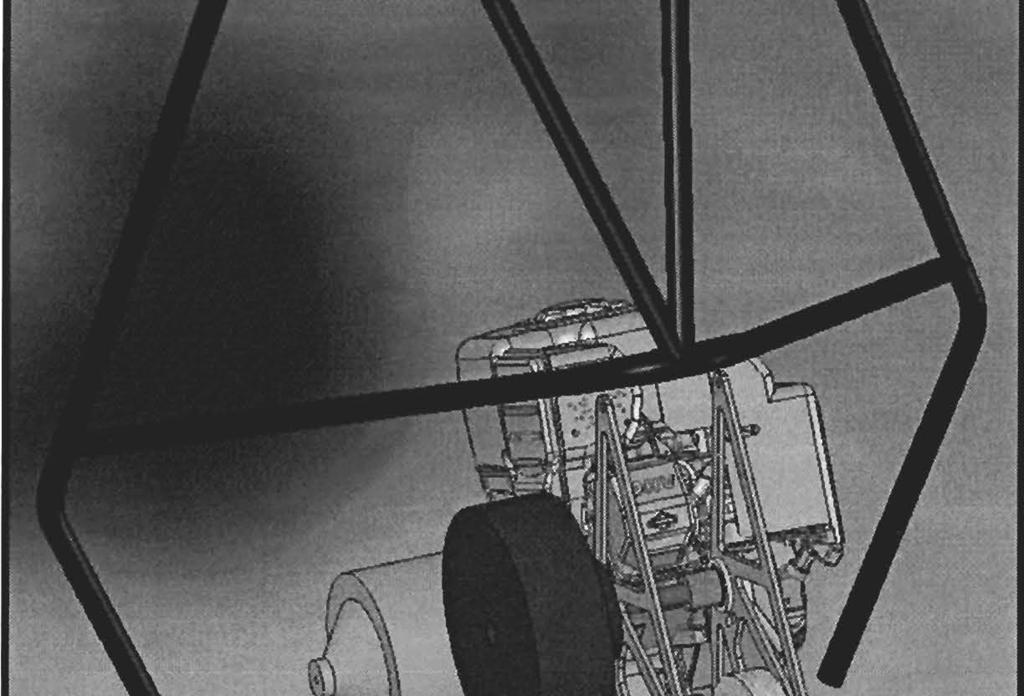
11 APPENDIX B: ADDITIONAL FIGURES AND CHARTS Figure 17: Final Chassis Geometry Figure 18: Front Suspension Model Figure 19: Rear Suspension Model


 Figure")


12 Experimental Jump Landing Damper Velocities ~ 'g -30 Cii >... ~ E -50 II Time (seconds) Figure 20: Experimental Jump Landing Damper Velocities Figure 21: Finite difference suspension simulation results


13 Figure 22: Briggs and Stratton Model 20 Governed Power Curve Figure 23: Rear Drive Assembly


14 Figure 24: Aluminum Subframe Prepared for Heat Treatment Figure 25: Sample Rear Drive FEA results
SAE Mini BAJA: Suspension and Steering
 SAE Mini BAJA: Suspension and Steering By Zane Cross, Kyle Egan, Nick Garry, Trevor Hochhaus Team 11 Progress Report Submitted towards partial fulfillment of the requirements for Mechanical Engineering
Design and Analysis of suspension system components
 Design and Analysis of suspension system components Manohar Gade 1, Rayees Shaikh 2, Deepak Bijamwar 3, Shubham Jambale 4, Vikram Kulkarni 5 1 Student, Department of Mechanical Engineering, D Y Patil college
ASME Human Powered Vehicle
 ASME Human Powered Vehicle By Yousef Alanzi, Evan Bunce, Cody Chenoweth, Haley Flenner, Brent Ives, and Connor Newcomer Team 14 Mid-Point Review Document Submitted towards partial fulfillment of the requirements
Design of Suspension and Steering system for an All-Terrain Vehicle and their Interdependence
 Design of Suspension and Steering system for an All-Terrain Vehicle and their Interdependence Saurabh Wanganekar 1, Chinmay Sapkale 2, Priyanka Chothe 3, Reshma Rohakale 4,Samadhan Bhosale 5 1 Student,Department
University of Wisconsin-Platteville Formula SAE Design Report
 2012-2013 University of Wisconsin-Platteville Formula SAE Design Report Introduction The 2012-2013 University of Wisconsin-Platteville Formula SAE Team is competing in Formula SAE, Nebraska, for the second
2012 Dalhousie University Formula SAE Design Report
 Dalhousie University Car #47 - Formula SAE Michigan fsae@dal.ca Introduction 2012 Dalhousie University Formula SAE Design Report The 2012 Dalhousie University Formula SAE Team is competing in Formula SAE,
MODELING SUSPENSION DAMPER MODULES USING LS-DYNA
 MODELING SUSPENSION DAMPER MODULES USING LS-DYNA Jason J. Tao Delphi Automotive Systems Energy & Chassis Systems Division 435 Cincinnati Street Dayton, OH 4548 Telephone: (937) 455-6298 E-mail: Jason.J.Tao@Delphiauto.com
SAE Mini Baja. Final Presentation. Benjamin Bastidos, Jeramie Goodwin, Eric Lockwood Anthony McClinton, Caizhi Ming, Ruoheng Pan May 2, 2014
 SAE Mini Baja Final Presentation Benjamin Bastidos, Jeramie Goodwin, Eric Lockwood Anthony McClinton, Caizhi Ming, Ruoheng Pan May 2, 2014 Overview Project Introduction Need Statement Frame Design and
DESIGN AND ANALYSIS OF TUBULAR CHASSIS OF GO-KART
 DESIGN AND ANALYSIS OF TUBULAR CHASSIS OF GO-KART Prashant Thakare 1, Rishikesh Mishra 2, Kartik Kannav 3, Nikunj Vitalkar 4, Shreyas Patil 5, Snehal Malviya 6 1 UG Students, Department of Mechanical Engineering,
NEW DESIGN AND DEVELELOPMENT OF ESKIG MOTORCYCLE
 NEW DESIGN AND DEVELELOPMENT OF ESKIG MOTORCYCLE Eskinder Girma PG Student Department of Automobile Engineering, M.I.T Campus, Anna University, Chennai-44, India. Email: eskindergrm@gmail.com Mobile no:7299391869
Design & Manufacturing of an Effective Steering System for a Formula Student Car
 Design & Manufacturing of an Effective Steering System for a Formula Student Car Nikhil N. Gitay 1, Siddharth A. Joshi 2, Ajit A. Dumbre 3, Devesh C. Juvekar 4 1,2,3,4 Student, Department of Mechanical
DESIGN AND DEVELOPMENT OF IC ENGINE GO-KART
 DESIGN AND DEVELOPMENT OF IC ENGINE GO-KART AkshayB. Khot 1, KunalJ. Mahekar 2, VaibhavJ. Mahekar 3, GurunathS. Patil 4, MohanishM. Patil 5, Prof. S. P. Jarag 6 BE Student, Department of Mechanical Engineering,
SAE Mini BAJA: Suspension and Steering
 SAE Mini BAJA: Suspension and Steering By Zane Cross, Kyle Egan, Nick Garry, Trevor Hochhaus Team 11 Project Progress Submitted towards partial fulfillment of the requirements for Mechanical Engineering
IJSRD - International Journal for Scientific Research & Development Vol. 5, Issue 03, 2017 ISSN (online):
:") IJSRD - International Journal for Scientific Research & Development Vol. 5, Issue 03, 2017 ISSN (online): 2321-0613 Design and Analysis of Suspension Component of F1 Prototype Ajay Kumar 1 Rahul Rajput
IJSRD - International Journal for Scientific Research & Development Vol. 5, Issue 03, 2017 ISSN (online): 2321-0613 Design and Analysis of Suspension Component of F1 Prototype Ajay Kumar 1 Rahul Rajput
SAE Baja - Drivetrain
 SAE Baja - Drivetrain By Ricardo Inzunza, Brandon Janca, Ryan Worden Team 11 Engineering Analysis Document Submitted towards partial fulfillment of the requirements for Mechanical Engineering Design I
Design And Development Of Roll Cage For An All-Terrain Vehicle
 Design And Development Of Roll Cage For An All-Terrain Vehicle Khelan Chaudhari, Amogh Joshi, Ranjit Kunte, Kushal Nair E-mail : khelanchoudhary@gmail.com, amogh_4291@yahoo.co.in,ranjitkunte@gmail.com,krockon007@gmail.com
Design, Modelling & Analysis of Double Wishbone Suspension System
 Design, Modelling & Analysis of Double Wishbone Suspension System 1 Nikita Gawai, 2 Deepak Yadav, 3 Shweta Chavan, 4 Apoorva Lele, 5 Shreyash Dalvi Thakur College of Engineering & Technology, Kandivali
ISSN: [Patil et al., 5(10): October, 2016] Impact Factor: 4.116
![ISSN: [Patil et al., 5(10): October, 2016] Impact Factor: 4.116](/thumbs/83/88212336.jpg "ISSN: [Patil et al., 5(10): October, 2016] Impact Factor: 4.116") IJESRT INTERNATIONAL JOURNAL OF ENGINEERING SCIENCES & RESEARCH TECHNOLOGY DESIGN AND ANALYSIS OF TELESCOPIC HALFSHAFT FOR AN ALL-TERRAIN VEHICLE (ATV) Chirag Patil *, Sandeep Imale, Kiran Hiware, Sumeet
IJESRT INTERNATIONAL JOURNAL OF ENGINEERING SCIENCES & RESEARCH TECHNOLOGY DESIGN AND ANALYSIS OF TELESCOPIC HALFSHAFT FOR AN ALL-TERRAIN VEHICLE (ATV) Chirag Patil *, Sandeep Imale, Kiran Hiware, Sumeet
Finite Element Modeling and Analysis of Vehicle Space Frame with Experimental Validation
 Finite Element Modeling and Analysis of Vehicle Space Frame with Experimental Validation Assoc. Prof Dr. Mohammed A.Elhaddad Mechanical Engineering Department Higher Technological Institute, Town of 6
Vehicle Dynamic Simulation Using A Non-Linear Finite Element Simulation Program (LS-DYNA)
") Vehicle Dynamic Simulation Using A Non-Linear Finite Element Simulation Program (LS-DYNA) G. S. Choi and H. K. Min Kia Motors Technical Center 3-61 INTRODUCTION The reason manufacturers invest their time
Vehicle Dynamic Simulation Using A Non-Linear Finite Element Simulation Program (LS-DYNA) G. S. Choi and H. K. Min Kia Motors Technical Center 3-61 INTRODUCTION The reason manufacturers invest their time
Design of Formula SAE Suspension
 SAE TECHNICAL PAPER SERIES 2002-01-3310 Design of Formula SAE Suspension Badih A. Jawad and Jason Baumann Lawrence Technological University Reprinted From: Proceedings of the 2002 SAE Motorsports Engineering
Skid against Curb simulation using Abaqus/Explicit
 Visit the SIMULIA Resource Center for more customer examples. Skid against Curb simulation using Abaqus/Explicit Dipl.-Ing. A. Lepold (FORD), Dipl.-Ing. T. Kroschwald (TECOSIM) Abstract: Skid a full vehicle
ME 455 Lecture Ideas, Fall 2010
 ME 455 Lecture Ideas, Fall 2010 COURSE INTRODUCTION Course goal, design a vehicle (SAE Baja and Formula) Half lecture half project work Group and individual work, integrated Design - optimal solution subject
Designing and Hard Point Optimization of Suspension System of a Three-Wheel Hybrid Vehicle
 ISSN (O): 2393-8609 International Journal of Aerospace and Mechanical Engineering Designing and Hard Point Optimization of Suspension System of a Three-Wheel Hybrid Vehicle Gomish Chawla B.Tech Automotive
TRANSLATION (OR LINEAR)
") 5) Load Bearing Mechanisms Load bearing mechanisms are the structural backbone of any linear / rotary motion system, and are a critical consideration. This section will introduce most of the more common
5) Load Bearing Mechanisms Load bearing mechanisms are the structural backbone of any linear / rotary motion system, and are a critical consideration. This section will introduce most of the more common
Finite Element Analysis of Clutch Piston Seal
 Finite Element Analysis of Clutch Piston Seal T. OYA * F. KASAHARA * *Research & Development Center Tribology Research Department Three-dimensional finite element analysis was used to simulate deformation
Design and Analysis of Go-kart Chassis
 Design and Analysis of Go-kart Chassis Sannake Aniket S. 1, Shaikh Sameer R. 2, Khandare Shubham A. 3 Prof. S.A.Nehatrao 4 1,2,3 BE Student, mechanical Department, N.B.Navale Sinhagad College Of Engineering,
DESIGN AND ANALYSIS OF PUSH ROD ROCKER ARM SUSPENSION USING MONO SPRING
 Volume 114 No. 9 2017, 465-475 ISSN: 1311-8080 (printed version); ISSN: 1314-3395 (on-line version) url: http://www.ijpam.eu ijpam.eu DESIGN AND ANALYSIS OF PUSH ROD ROCKER ARM SUSPENSION USING MONO SPRING
FEASIBILITY STYDY OF CHAIN DRIVE IN WATER HYDRAULIC ROTARY JOINT
 FEASIBILITY STYDY OF CHAIN DRIVE IN WATER HYDRAULIC ROTARY JOINT Antti MAKELA, Jouni MATTILA, Mikko SIUKO, Matti VILENIUS Institute of Hydraulics and Automation, Tampere University of Technology P.O.Box
Design, analysis and mounting implementation of lateral leaf spring in double wishbone suspension system
 Design, analysis and mounting implementation of lateral leaf spring in double wishbone suspension system Rahul D. Sawant 1, Gaurav S. Jape 2, Pratap D. Jambhulkar 3 ABSTRACT Suspension system of an All-TerrainVehicle
Design and optimization of Double wishbone suspension system for ATVs
 Design and optimization of Double wishbone suspension system for ATVs Shantanu Garud 1, Pritam Nagare 2, Rohit Kusalkar 3, Vijaysingh Gadhave 4, Ajinkya Sawant 5 1,2,3,4Dept of Mechanical Engineering,
New Frontier in Energy, Engineering, Environment & Science (NFEEES-2018 ) Feb
 Feb") RESEARCH ARTICLE OPEN ACCESS DESIGN AND IMPACT ANALYSIS OF A ROLLCAGE FOR FORMULA HYBRID VEHICLE Aayush Bohra 1, Ajay Sharma 2 1(Mechanical department, Arya College of Engineering & I.T.,kukas, Jaipur)
RESEARCH ARTICLE OPEN ACCESS DESIGN AND IMPACT ANALYSIS OF A ROLLCAGE FOR FORMULA HYBRID VEHICLE Aayush Bohra 1, Ajay Sharma 2 1(Mechanical department, Arya College of Engineering & I.T.,kukas, Jaipur)
Torsional analysis of the chassis and its validation through Finite. Element Analysis
 Torsional analysis of the chassis and its validation through Finite Ayush Anand Student(Production) BIT Mesra,Ranchi, Jharkhand-835215,India ayush.aand@gmail.com Element Analysis Keywords: Roll cage, Torsional
Design Methodology of Steering System for All-Terrain Vehicles
 Design Methodology of Steering System for All-Terrain Vehicles Dr. V.K. Saini*, Prof. Sunil Kumar Amit Kumar Shakya #1, Harshit Mishra #2 *Head of Dep t of Mechanical Engineering, IMS Engineering College,
SAE Mini Baja: Suspension and Steering
 SAE Mini Baja: Suspension and Steering Project Proposal Zane Cross, Kyle Egan, Nick Garry, Trevor Hochhaus NAU December 3, 2014 Overview 2 Problem Definition and Project Plan Concept Generation Design
VEHICLE ANTI-ROLL BAR ANALYZED USING FEA TOOL ANSYS
 VEHICLE ANTI-ROLL BAR ANALYZED USING FEA TOOL ANSYS P. M. Bora 1, Dr. P. K. Sharma 2 1 M. Tech. Student,NIIST, Bhopal(India) 2 Professor & HOD,NIIST, Bhopal(India) ABSTRACT The aim of this paper is to
Analysis and control of vehicle steering wheel angular vibrations
 Analysis and control of vehicle steering wheel angular vibrations T. LANDREAU - V. GILLET Auto Chassis International Chassis Engineering Department Summary : The steering wheel vibration is analyzed through
Six keys to achieving better precision in linear motion control applications
 profile Drive & Control Six keys to achieving better precision in linear motion control applications Achieving precise linear motion Consider these factors when specifying linear motion systems: Equipped
I. Tire Heat Generation and Transfer:
 Caleb Holloway - Owner calebh@izzeracing.com +1 (443) 765 7685 I. Tire Heat Generation and Transfer: It is important to first understand how heat is generated within a tire and how that heat is transferred
SUMMARY OF STANDARD K&C TESTS AND REPORTED RESULTS
 Description of K&C Tests SUMMARY OF STANDARD K&C TESTS AND REPORTED RESULTS The Morse Measurements K&C test facility is the first of its kind to be independently operated and made publicly available in
Development of a Multibody Systems Model for Investigation of the Effects of Hybrid Electric Vehicle Powertrains on Vehicle Dynamics.
 Development of a Multibody Systems Model for Investigation of the Effects of Hybrid Electric Vehicle Powertrains on Vehicle Dynamics. http://dx.doi.org/10.3991/ijoe.v11i6.5033 Matthew Bastin* and R Peter
Design and Integration of Suspension, Brake and Steering Systems for a Formula SAE Race Car
 Design and Integration of Suspension, Brake and Steering Systems for a Formula SAE Race Car Mark Holveck 01, Rodolphe Poussot 00, Harris Yong 00 Final Report May 5, 2000 MAE 340/440 Advisor: Prof. S. Bogdonoff
126 Ridge Road Tel: (607) PO Box 187 Fax: (607)
 PO Box 187 Fax: (607)") 1. Summary Finite element modeling has been used to determine deflections and stress levels within the SRC planar undulator. Of principal concern is the shift in the magnetic centerline and the rotation
1. Summary Finite element modeling has been used to determine deflections and stress levels within the SRC planar undulator. Of principal concern is the shift in the magnetic centerline and the rotation
DESIGN AND OPTIMIZATION OF HTV FUEL TANK ASSEMBLY BY FINITE ELEMENT ANALYSIS
 DESIGN AND OPTIMIZATION OF HTV FUEL TANK ASSEMBLY BY FINITE ELEMENT ANALYSIS GAJENDRA G 1, PRAKASHA A M 2, DR NOOR AHMED R 3, DR.K.S.BADRINARAYAN 4 1PG Scholar, Mechanical department, M S Engineering College,
University of Alberta Design Report
 University of Alberta Design Report INTRODUCTION The University of Alberta has been a competitor in the Formula SAE competition since 1999. Those years of experience have provided the team with many lessons
SAE Mini Baja By Ahmed Alnattar, Neil Gehr, and Matthew Legg Team 11
 SAE Mini Baja 2014-2015 By Ahmed Alnattar, Neil Gehr, and Matthew Legg Team 11 Final Report Document April 22, 2015 Submitted towards partial fulfillment of the requirements for Mechanical Engineering
Technical Report Lotus Elan Rear Suspension The Effect of Halfshaft Rubber Couplings. T. L. Duell. Prepared for The Elan Factory.
 Technical Report - 9 Lotus Elan Rear Suspension The Effect of Halfshaft Rubber Couplings by T. L. Duell Prepared for The Elan Factory May 24 Terry Duell consulting 19 Rylandes Drive, Gladstone Park Victoria
Assemblies for Parallel Kinematics. Frank Dürschmied. INA reprint from Werkstatt und Betrieb Vol. No. 5, May 1999 Carl Hanser Verlag, München
 Assemblies for Parallel Kinematics Frank Dürschmied INA reprint from Werkstatt und Betrieb Vol. No. 5, May 1999 Carl Hanser Verlag, München Assemblies for Parallel Kinematics Frank Dürschmied Joints and
Increase Factor of Safety of Go-Kart Chassis during Front Impact Analysis
 IJIRST International Journal for Innovative Research in Science & Technology Volume 3 Issue 04 September 2016 ISSN (online): 2349-6010 Increase Factor of Safety of Go-Kart Chassis during Front Impact Analysis
2017 Baja SAE Competition
 2017 Baja SAE Competition Meet the Team Enrique DeLeon Manjula Hodekar Keith Hernandez Mechanical Lead Public Relations Design Lead Logistics Team Lead Project Management Instructor: Dr. Raresh Pascali
Chapter 7: Thermal Study of Transmission Gearbox
 Chapter 7: Thermal Study of Transmission Gearbox 7.1 Introduction The main objective of this chapter is to investigate the performance of automobile transmission gearbox under the influence of load, rotational
SAE Baja: Project Proposal Suspension and Steering
 SAE Baja: Project Proposal Suspension and Steering Benjamin Bastidos, Victor Cabilan, Jeramie Goodwin, William Mitchell, Eli Wexler Wednesday, November 20, 2013 Overview Introduction Concept Generation
ANALYSIS OF GEAR QUALITY CRITERIA AND PERFORMANCE OF CURVED FACE WIDTH SPUR GEARS
 8 FASCICLE VIII, 8 (XIV), ISSN 11-459 Paper presented at Bucharest, Romania ANALYSIS OF GEAR QUALITY CRITERIA AND PERFORMANCE OF CURVED FACE WIDTH SPUR GEARS Laurentia ANDREI 1), Gabriel ANDREI 1) T, Douglas
Simulating Rotary Draw Bending and Tube Hydroforming
 Abstract: Simulating Rotary Draw Bending and Tube Hydroforming Dilip K Mahanty, Narendran M. Balan Engineering Services Group, Tata Consultancy Services Tube hydroforming is currently an active area of
FRONTAL OFF SET COLLISION
 FRONTAL OFF SET COLLISION MARC1 SOLUTIONS Rudy Limpert Short Paper PCB2 2014 www.pcbrakeinc.com 1 1.0. Introduction A crash-test-on- paper is an analysis using the forward method where impact conditions
Heat treatment Elimination in Forged steel Crankshaft of Two-stage. compressor.
 Research Journal of Engineering Sciences ISSN 2278 9472 Heat treatment Elimination in Forged steel Crankshaft of Two-stage Compressor Abstract Lakshmanan N. 1, Ramachandran G.M. 1 and Saravanan K. 2 1
Simulation. Muscle. Sporty Concept C. Putting
 Putting Simulation Muscle Be Sporty Concept C by Beverly A. Beckert Sporting spirit. Performance. Technology. Driving pleasure. Steering wheel feel. Control. That s what Alfa Romeo captures in all of its
MODELS FOR THE DYNAMIC ANALYSIS OF THE SUSPENSION SYSTEM OF THE VEHICLES REAR AXLE
 MODELS FOR THE DYNAMIC ANALYSIS OF THE SUSPENSION SYSTEM OF THE VEHICLES REAR AXLE Alexandru Cătălin Transilvania University of Braşov, Product Design and Robotics Department, calex@unitbv.ro Keywords:
Load Cell for Manually Operated Presses Model 8451
 w Technical Product Information Load Cell for Manually Operated Presses 1. Introduction... 2 2. Preparing for use... 2 2.1 Unpacking... 2 2.2 Using the instrument for the first time... 2 2.3 Grounding
Test-bed for Bose Speaker Impact Stress Analysis
 Test-bed for Bose Speaker Impact Stress Analysis Design Team Deema AlHasan, Rafael Hernandez Lourdes Sanfeliu, Ahmad Zameli Design Advisor Prof. Sagar Kamarthi Sponsor Harry Malkasian Abstract Bose, an
2012 Baja SAE Drivetrain
 2012 Baja SAE Drivetrain A thesis submitted to the Faculty of the Mechanical Engineering Technology Program of the University of Cincinnati in partial fulfillment of the requirements for the degree of
Design of Helical Gear and Analysis on Gear Tooth
 Design of Helical Gear and Analysis on Gear Tooth Indrale Ratnadeep Ramesh Rao M.Tech Student ABSTRACT Gears are mainly used to transmit the power in mechanical power transmission systems. These gears
Structural Analysis of Student Formula Race Car Chassis
 Structural Analysis of Student Formula Race Car Chassis Arindam Ghosh 1, Rishika Saha 2, Sourav Dhali 3, Adrija Das 4, Prasid Biswas 5, Alok Kumar Dubey 6 1Assistant Professor, Dept. of Mechanical Engineering,
LESSON Transmission of Power Introduction
 LESSON 3 3.0 Transmission of Power 3.0.1 Introduction Earlier in our previous course units in Agricultural and Biosystems Engineering, we introduced ourselves to the concept of support and process systems
SPMM OUTLINE SPECIFICATION - SP20016 issue 2 WHAT IS THE SPMM 5000?
 SPMM 5000 OUTLINE SPECIFICATION - SP20016 issue 2 WHAT IS THE SPMM 5000? The Suspension Parameter Measuring Machine (SPMM) is designed to measure the quasi-static suspension characteristics that are important
Factors Influencing the Performance of Ball and Rolling Bearings
 Factors Influencing the Performance of Ball and Rolling Bearings Course No: M02-033 Credit: 2 PDH Robert P. Tata, P.E. Continuing Education and Development, Inc. 9 Greyridge Farm Court Stony Point, NY
SIX-BAR STEERING MECHANISM
 SIX-BAR STEERING MECHANISM Shrey Lende 1 1 UG Student, Department of Mech, G.H Raisoni College of Engineering, Nagpur, RTMN University ABSTRACT In this paper a steering system is designed for a Low weight
Variable Valve Drive From the Concept to Series Approval
 Variable Valve Drive From the Concept to Series Approval New vehicles are subject to ever more stringent limits in consumption cycles and emissions. At the same time, requirements in terms of engine performance,
FX-HR Holden Front End - 800kg axle rating - manufactured after August 2010
 Project: CO0048 Re: FX-HR Holden Front End - 800kg axle rating - manufactured after August 2010 Stress Analysis & Geometry Assessment Prepared for: V6 Conversions Date: 2 nd December 2010 By: Brett Longhurst
Surface- and Pressure-Dependent Characterization of SAE Baja Tire Rolling Resistance
 Surface- and Pressure-Dependent Characterization of SAE Baja Tire Rolling Resistance Abstract Cole Cochran David Mikesell Department of Mechanical Engineering Ohio Northern University Ada, OH 45810 Email:
A double-wishbone type suspension is used in the front. A multi-link type suspension is used in the rear. Tread* mm (in.) 1560 (61.
 1560 (61.") CHASSIS SUSPENSION AND AXLE CH-69 SUSPENSION AND AXLE SUSPENSION 1. General A double-wishbone type suspension is used in the front. A multi-link type suspension is used in the rear. 08D0CH111Z Specifications
CHASSIS SUSPENSION AND AXLE CH-69 SUSPENSION AND AXLE SUSPENSION 1. General A double-wishbone type suspension is used in the front. A multi-link type suspension is used in the rear. 08D0CH111Z Specifications
Safety factor and fatigue life effective design measures
 Safety factor and fatigue life effective design measures Many catastrophic failures have resulted from underestimation of design safety and/or fatigue of structures. Failure examples of engineered structures
Load cells for a Portable Structure
 Load cells for a Portable Structure Load Restoring force Side force We know that a weighing system must be rigid to get good results. We should also know that a three point system is inherently more stable
CHAPTER 5 PREVENTION OF TOOTH DAMAGE IN HELICAL GEAR BY PROFILE MODIFICATION
 90 CHAPTER 5 PREVENTION OF TOOTH DAMAGE IN HELICAL GEAR BY PROFILE MODIFICATION 5.1 INTRODUCTION In any gear drive the absolute and the relative transmission error variations normally increases with an
Introducing Galil's New H-Bot Firmware
 March-16 Introducing Galil's New H-Bot Firmware There are many applications that require movement in planar space, or movement along two perpendicular axes. This two dimensional system can be fitted with
Using ABAQUS in tire development process
 Using ABAQUS in tire development process Jani K. Ojala Nokian Tyres plc., R&D/Tire Construction Abstract: Development of a new product is relatively challenging task, especially in tire business area.
SAE Mini Baja. Frame Team. Ahmed Alnattar, Neil Gehr, Matthew Legg. Project Proposal
 SAE Mini Baja Frame Team Project Proposal Ahmed Alnattar, Neil Gehr, Matthew Legg 12-3-14 1 Overview Introduction Customer s Needs and Project Goals Constraints, Objectives, QFD, and Timeline Concept Generation
Tech Tip: Trackside Tire Data
 Using Tire Data On Track Tires are complex and vitally important parts of a race car. The way that they behave depends on a number of parameters, and also on the interaction between these parameters. To
ME scope Application Note 29 FEA Model Updating of an Aluminum Plate
 ME scope Application Note 29 FEA Model Updating of an Aluminum Plate NOTE: You must have a package with the VES-4500 Multi-Reference Modal Analysis and VES-8000 FEA Model Updating options enabled to reproduce
Fundamentals of Steering Systems ME5670
 Fundamentals of Steering Systems ME5670 Class timing Monday: 14:30 Hrs 16:00 Hrs Thursday: 16:30 Hrs 17:30 Hrs Lecture 3 Thomas Gillespie, Fundamentals of Vehicle Dynamics, SAE, 1992. http://www.me.utexas.edu/~longoria/vsdc/clog.html
Load Analysis and Multi Body Dynamics Analysis of Connecting Rod in Single Cylinder 4 Stroke Engine
 IJSRD - International Journal for Scientific Research & Development Vol. 3, Issue 08, 2015 ISSN (online): 2321-0613 Load Analysis and Multi Body Dynamics Analysis of Connecting Rod in Single Cylinder 4
Increase performance of all-terrain vehicle by tuning of various components
 Increase performance of all-terrain vehicle by tuning of various components Bhavdeep Trivedi Marut Patel Deep Patel Ripen Shah Asst. Professor, Mechanical Department, Silver Oak College of Engg. & Tech.,
Cane Creek Double Barrel Instructions
 Cane Creek Double Barrel Instructions Congratulations on your purchase of the Cane Creek Double Barrel rear shock. Developed in partnership with Öhlins Racing, the Double Barrel brings revolutionary suspension
EXPERIMENTAL ANALYSIS AND TOPOLOGY OPTIMIZATION OF LOWER SUSPENSION ARM OF CAR
 EXPERIMENTAL ANALYSIS AND TOPOLOGY OPTIMIZATION OF LOWER SUSPENSION ARM OF CAR Rupali Dhore 1, Prof. M.L. Thorat 2 1B.E.MECH. (M.E.Pursuing), Mechanical Department, RMD SINHGAD SCHOOL OF ENGINEERING, PUNE
Smart Automated Vent Register Using an SMA Spring Actuated Rotary Ratchet
 Smart Automated Vent Register Using an SMA Spring Actuated Rotary Ratchet Mary Molepske, Victor Braciszewski, James Butler, Gregory Caputo, Fan-Ning Cheng, WonHee Kim, Jonathan Luntz, Diann Brei ABSTRACT
Basic Wheel Alignment Techniques
 Basic Wheel Alignment Techniques MASTERING THE BASICS: Modern steering and suspension systems are great examples of solid geometry at work. Wheel alignment integrates all the factors of steering and suspension
SPMM OUTLINE SPECIFICATION - SP20016 issue 2 WHAT IS THE SPMM 5000?
 SPMM 5000 OUTLINE SPECIFICATION - SP20016 issue 2 WHAT IS THE SPMM 5000? The Suspension Parameter Measuring Machine (SPMM) is designed to measure the quasi-static suspension characteristics that are important
Linear Shaft Motors in Parallel Applications
 Linear Shaft Motors in Parallel Applications Nippon Pulse s Linear Shaft Motor (LSM) has been successfully used in parallel motor applications. Parallel applications are ones in which there are two or
Procedia Engineering 00 (2009) Mountain bike wheel endurance testing and modeling. Robin C. Redfield a,*, Cory Sutela b
 Mountain bike wheel endurance testing and modeling. Robin C. Redfield a,*, Cory Sutela b") Procedia Engineering (29) Procedia Engineering www.elsevier.com/locate/procedia 9 th Conference of the International Sports Engineering Association (ISEA) Mountain bike wheel endurance testing and modeling
Procedia Engineering (29) Procedia Engineering www.elsevier.com/locate/procedia 9 th Conference of the International Sports Engineering Association (ISEA) Mountain bike wheel endurance testing and modeling
SOME FACTORS THAT INFLUENCE THE PERFORMANCE OF
 SOME FACTORS THAT INFLUENCE THE PERFORMANCE OF Authored By: Robert Pulford Jr. and Engineering Team Members Haydon Kerk Motion Solutions There are various parameters to consider when selecting a Rotary
Dynamic Load Analysis and Optimization of a Fracture-Split Connecting Rod
 Dynamic Load Analysis and Optimization of a Fracture-Split Connecting Rod Dipak Sarmah, Athar M Khan and Anirudh Jaipuria Ashok Leyland Ltd. India. Abstract: This paper summarizes the methodology to design
08-09 Suspension Design Analysis
 Jonathan Peyton Independent Design Study 08-09 Suspension Design Analysis Summary: The chasiss of the 08-09 car was redesigned to have a shorter wheelbase by two inches and a wider rear track by two and
MAIN SHAFT SUPPORT FOR WIND TURBINE WITH A FIXED AND FLOATING BEARING CONFIGURATION
 Technical Paper MAIN SHAFT SUPPORT FOR WIND TURBINE WITH A FIXED AND FLOATING BEARING CONFIGURATION Tapered Double Inner Row Bearing Vs. Spherical Roller Bearing On The Fixed Position Laurentiu Ionescu,
iracing.com Williams-Toyota FW31 Quick Car Setup Guide
 iracing.com Williams-Toyota FW31 Quick Car Setup Guide In this guide we will briefly explain a number of key setup parameters which are distinct to the FW31 and which are new to iracing vehicles. We hope
MIKLOS Cristina Carmen, MIKLOS Imre Zsolt UNIVERSITY POLITEHNICA TIMISOARA FACULTY OF ENGINEERING HUNEDOARA ABSTRACT:
 1 2 THEORETICAL ASPECTS ABOUT THE ACTUAL RESEARCH CONCERNING THE PHYSICAL AND MATHEMATICAL MODELING CATENARY SUSPENSION AND PANTOGRAPH IN ELECTRIC RAILWAY TRACTION MIKLOS Cristina Carmen, MIKLOS Imre Zsolt
Part 1. The three levels to understanding how to achieve maximize traction.
 Notes for the 2017 Prepare to Win Seminar Part 1. The three levels to understanding how to achieve maximize traction. Level 1 Understanding Weight Transfer and Tire Efficiency Principle #1 Total weight
FE Modeling and Analysis of a Human powered/electric Tricycle chassis
 FE Modeling and Analysis of a Human powered/electric Tricycle chassis Sahil Kakria B.Tech, Mechanical Engg UCOE, Punjabi University Patiala, Punjab-147004 kakria.sahil@gmail.com Abbreviations: SAE- Society
Development of Rattle Noise Analysis Technology for Column Type Electric Power Steering Systems
 TECHNICAL REPORT Development of Rattle Noise Analysis Technology for Column Type Electric Power Steering Systems S. NISHIMURA S. ABE The backlash adjustment mechanism for reduction gears adopted in electric
Kinematic Analysis of Roll Motion for a Strut/SLA Suspension System Yung Chang Chen, Po Yi Tsai, I An Lai
 Kinematic Analysis of Roll Motion for a Strut/SLA Suspension System Yung Chang Chen, Po Yi Tsai, I An Lai Abstract The roll center is one of the key parameters for designing a suspension. Several driving
Analysis of Eclipse Drive Train for Wind Turbine Transmission System
 ISSN 2395-1621 Analysis of Eclipse Drive Train for Wind Turbine Transmission System #1 P.A. Katre, #2 S.G. Ganiger 1 pankaj12345katre@gmail.com 2 somu.ganiger@gmail.com #1 Department of Mechanical Engineering,