PRE-CRASH TRIGGERED PRETENSIONING OF THE SEAT BELT FOR IMPROVED SAFETY
|
|
|
- Bridget Cunningham
- 6 years ago
- Views:
Transcription
1 PRE-CRASH TRIGGERED PRETENSIONING OF THE SEAT BELT FOR IMPROVED SAFETY Bengt Pipkorn Autoliv Research SWEDEN Jacob Wass Sigma Industry West SWEDEN Paper Number ABSTRACT The potential injury reducing benefits of pre-crash belt slack reduction of a motorized seat belt system was evaluated. The evaluation was carried out for 1 second pre-crash braking followed by a 56km/h full frontal rigid wall crash. For the evaluation a validated active human body model and a model of the THOR dummy were used. The active human body model is capable of, and validated for, predicting occupant kinematics during pre-crash braking and occupant response for crash loading. In the study substantial belt slack was introduced by adding 100mm thick foam pads between the occupant and belt. Pads were added between the chest portion of the seat belt and the chest and between the lap portion of the belt and the pelvis. The effect of 300N and 600N pre-crash pretensioning (pre-pretensioning) of the belt on occupant kinematics and chest deflection during 1 second braking followed by a 56km/h full frontal rigid wall crash was evaluated. In addition the effect of in-crash triggered pyrotechnic pretensioning of the belt was also evaluated. It was found that pre-crash forward excursion of the occupant during braking was reduced by prepretensioning the belt. The forward excursion was reduced for both the occupant without slack and the occupant with 100mm slack. For pre-crash braking followed by a crash generally chest deflections were reduced with pre-crash pretensioning of the belt. Reductions were obtained for the occupant without slack as well as for the occupant with 100mm slack. However, greater reductions was obtained for the occupant with 100mm slack than for the occupant without slack. It was also generally found that additional reductions in chest deflection was obtained for the in crash activated pyrotechnic pretensioners. Pipkorn
2 BACKGROUND Seat belts decrease automobile-related fatalities and injuries [1] & [2]. They achieve this benefit by reducing the peak loads applied to the occupants, applying these loads to anatomical structures better able to handle high loads, and limiting occupant excursion and thus the probability of contact inside the vehicle. Seat belts function optimally when worn snugly. When not snug, the additional slack in the seat belt was shown to increase the displacement of the head, chest, hips, and knees in high-speed frontal impacts [3] [4] [5]. Prior to a collision, seat belt slack can be introduced by poor seat belt adjustment, bulky clothing, or tension-relieving devices incorporated into some seat belt retractors. In a study it was found that for approaching 10% of the vehicle occupants the slack in the shoulder belt was greater than 75mm [6]. During a collision, seat belt slack can be introduced by tightening of the webbing on the spool after the retractor locks [7]. Whether introduced before or during a collision, the larger displacements caused by seat belt slack increase both the potential for occupant contact with interior structures and the severity of contacts that can occur even with a snug belt. Today, real-world occupant protection is more than simply conventional passive safety technologies, such as seatbelts and airbags. During the last decade, rapid development of auto-brake technologies has taken place. Today most vehicle manufacturers offer some form of collision avoidance systems on their vehicles, at least as an option package [8]. In conjunction with the autonomous emergency braking (AEB) system, the motorised pre-pretensioner (PPT) system was introduced in order to reduce the degree of an occupant leaving the designed-position [9]. To comprehensively assess the benefit of introducing so-called integrated safety systems (e.g. motorised PPT systems in conjunction with AEB) an appropriate occupant model must be used. The occupant model should represent occupant responses, not only for in-crash loading, but preceding pre-crash loading. In order to predict human posture maintenance and human-like reflexive responses during pre-impact braking, a finite element human body model with proportional integral derivative (PID) controlled Hill-type active muscle system model was developed by Östh et al. (2012) [10]. The neuromuscular feedback control was implemented for the Total HUman Model for Safety (THUMS) AM50 version 3.0 [11], with some enhancements to the model [12]. The developed model the so-called SAFER AHBM with an active muscle system, was able to capture the kinematic responses during AEB events, and muscle activation magnitude was similar to that of the volunteers [13]. The SAFER AHBM uses a 1D Hill-type model, as muscle representation, with muscles controlled by PID feedback, via stabilising muscle activation generated in response to external perturbation. Using the SAFER AHBM tool that can predict occupant kinematics pre-crash and the loads on the occupant in-crash the potential injury reducing benefits from reducing the slack in the belt by pre-pretensioning the belt during the braking phase of a vehicle can be evaluated. The aim of this study is to quantify the effect of seat belt slack on occupant response during precrash braking (1 sec) followed by a 56km/h crash. METHOD For the study the SAFER active human body model and a model of the THOR dummy [15] were used as occupant substitutes. The occupants were positioned in the driver side interior model of a mid size vehicle. The human body model and THOR dummy model were restrained by a state fo the art belt system comprising a seat belt retractor with a motorised pre-pretensioner, a pyrotechnic retractor pretensioner, a lap belt pretensioner, a retractor belt force limiter and a driver side airbag. The force limiter value of the retractor pretensioner was 4.0kN. Dashpanel, floor and toepan were also included in the model. Slack was introduced by adding 100mm thick soft foam pads between the seat belt and the thorax and pelvis of the occupant substitute. The foam pads were so soft that pulling the seatbelt between the shoulder of the occupant and the D- ring by hand would result in completely compressed foam pads and eliminated belt slack. Seat foam properties were used for the foam pads in the model (Figure 1). Pipkorn


3 Initially the incluence of braking only on occupant kinematics and chest deflection was evaluated. Thereafter the influence on occupant kinematics and chest deflection for various level of prepretensioning force was evaluated. The levels were 0, 300N and 600N. Lastly the influence of the pyrotechnic pretensioners on occupant kinematics and chest deflection was evaluated. Figure 1. Foam Pads to Introduce Slack For all evaluations the brake pulse was applied for 1.0 second at approximately 1g. The ramp up time for the pulse was 500ms. The 1.0 seconds pre-crash braking was followed by a crash at 56km/h (Figure 2). The retractor locked after 575ms. The 1 second pre-crash braking was followed by a full frontal crash at 56km/h in a rigid wall (Figure 3). Chest deflection for the active human body model was extracted at 4 locations (Figure 4). The upper locations were at the 4:th rib and the lower locations were between the 6:th and 7:th rib. For the THOR dummy model chest deflections were extracted from the 4 IRTRACCs. Greatest resulting deflection of the four measurement locations was selected for presentation in this paper. Figure 2. Brake Pulse Figure 4. Chest Transducer Locations for the Active Human Body Model RESULTS Figure 3. Crash Pulse Active Human Body Model For 1 second pre-crash braking greatest head and sternum excursions were obtained for the configuration with 100mm slack and no prepretensioning (Figure 5). For the configuration with 100mm slack the excursion with 300N and 600N pre-pretensioning was less than for the configuration without slack. For 100mm slack Pipkorn


4 small difference in head and sternum excursions for 300N and 600N was obtained. the belt chest excursion was 6mm greater for the occupant with 100mm slack (Figure 7). Chest deflection was reduced by 2mm for 300N and by 5mm for 600N pre-pretensioning. For 0mm slack small reductions in chest deflection was obtained for pre-pretensioning. 0mm Slack Initial position Standard seatbelt 300 N PPT 600 N PPT 100mm Slack Figure 5. Position at Crash after 1sec Pre-Brake For the crash only configuration in which precrash braking was not included it can be observed that for the belt system without slack the pyrotechnic pretensioners reduced chest deflection by approximately 4mm (Figure 6). For the belt system with 100mm slack the pyrotechnic pretensioners reduced chest deflection also by 4mm. Figure 7. Chest Deflection Pre-Pretensioning for Pre-Crash Braking with Pyrotechnic Pretensioner For 1 second pre-crash braking without pyrotechnic pretensioner and 0mm slack chest deflection was reduced when pre-pretensioning was added (Figure 8). For 100mm slack chest deflection was reduced by 5mm and 7mm respectively when 300N and 600N prepretensioning was added. For 100mm slack and no pre-pretensioning chest deflection was reduced with the pyrotechnic pretensioner (Figure 7). For 100mm slack and prepretensioning no reductions in chest deflection was observed for the pyrotechnic pretensioners (Figure 8 and 9). Figure 6. Chest Deflection for Crash Only For 1 second pre-crash braking with pyrotechnic pretensioners and without pre-pretensioning of Pipkorn


5 Figure 9. Chest Deflection for Crash Only Figure 8. Chest Deflection for Pre-Pretensioning for Pre- Crash Braking Without Pyrotechnic Pretensioner THOR Dummy Model With the purpose of confirming the observations from the analysis with the active human body model the THOR dummy model was exposed to the identical load conditions as the SAFER active human body model in the present study, 1 second braking followed by a 56km/h rigid wall crash. Generally the same trends was observed for the THOR dummy model as was observed for the active human body model. In the loadcase without pre-crash braking chest deflection was reduced by pyrotechnic pretensioners by approximately 7mm for both without and with 100mm slack (Figure 9). For the pre-crash activated pre-pretensioning chest deflection was reduced with prepretensioning for the occupant without slack (Figure 10). However, when the pre-pretensioning force was increased from 300N to 600N no additional reductions in chest deflection was obtained. For the occupant with 100mm slack chest deflection was reduced from 58mm to 48mm with 300N pre-pretensioning. For 600N prepretensioning chest deflection was reduced to 42mm. Figure 10. Chest Deflection Pre-Pretensioning for Pre-Crash Braking with Pyrotechnic Pretensioner Pipkorn

6 For the evaluation without pyrotechnic pretensioners chest deflection was reduced from 55mm to 49mm with 300N pre-pretensioning for the occupant without slack (Figure 11). For an increased pre-pretensioning force to 600N chest deflection was reduced to 45mm. For an occupant with 100mm slack chest deflection was reduced from 63mm to 50mm with 300N pre-pretensioning and to 44mm with 600N pre-pretensioning. For the evaluation of pyrotechnic pretensioners chest deflection was greater both without slack and with slack when the pyrotechnic pretensioners were not used (Figure 10 & Figure 11). However, for the occupant without slack and 600N pre-pretensioning no reductions in chest deflection was observed while for the occupant with 100mm slack chest deflection was reduced from 44 to 41mm. chest was increased chest deflection. In the study no modifications to the airbag were included. Figure 12. Active Human Body Model Peak forward excursion (100ms into the crash): Blue - 100mm slack no pre-pretensioning Red - 100mm slack with and 600N prepretensioning For both the active human body model and the THOR dummy model chest deflection was reduced for an occupant with 100mm slack when 300N and 600N pre-pretensioning was added (Figure 7, 8, 10 and 11). Figure 11. Chest Deflection for Pre-Pretensioning for Pre- Crash Braking Without Pyrotechnic Pretensioner DISCUSSION Generally 300N and 600N pre-pretensioning was found to reduce maximum forward excursion of both the active human body model and the THOR dummy model (Figure 12). Greatest total excursion was obtained for 100mm slack and no pre-pretensioning. The result from increased excursion was increased load on the chest from the airbag. The result from increased load on the For the active human body model without prepretensioning chest deflection was reduced for the occupant both without slack and with 100mm slack for the 1 second pre-crash braking loadcase compared to the crash only loadcase (Figure 6, 7 and 8). For the THOR dummy model the trend was the opposite. Chest deflection was increased for the occupant without slack and with 100mm slack without pre-pretensioning when pre-crash braking was added (Figure 9, 10 and 11). In the active human body model the hands were holding onto the steering wheel and the arm muscles were tensed to reduce forward motion during the precrash braking phase. The hands were released from the steering wheel at 30ms into the crash phase. Therefore the pre-crash kinematics predicted with the active human body model can be assumed to be more similar to human kinematics during pre-crash braking than the THOR kinematics for which pre-crash bracing with the arms was not included. Pipkorn


7 Reducing THOR dummy chest deflection from 57mm to 42mm for an occupant with 100mm slack by adding 600N pre-pretensioning in addition to the pyrotechnic pretensioning was found to reduce the risk to sustain an AIS3+ injury from 75% to 26% for a 45 year old occupant [13]. The THOR dummy model was included in the study to enable potential future mechanical verification of the results from the active human body model. Therefore, the ability of the THOR dummy to predict human kinematics in pre-crash braking was evaluated by mimicking the volunteer tests carried out by Östh et al. (2013) [14] with the THOR dummy (Figure 13). In the tests a passenger vehicle was travelling at 70km/h the velocity was reduced to 0km/h by appling the brakes during 2 seconds. The volunteers and THOR dummy were positioned in the passenger seat and restrained by a motor driven reversible seat belt. Head x-, y- and z-displacements and head rotations for THOR were compared to corresponding measurements for the volunteers. The volunteer tests were also virtually mimicked with the THOR dummy model (version 1.0) [15]. signals. The rating results ranges from 0 (no correlation) to 1 (perfect match). The CORA rating for the active human body model was good while the rating for the THOR dummy model was fair (Figure 14) [17]. For the THOR dummy model there was poor agreement for the head z-displacement. All other displacements for both the THOR dummy model and the active human body model were in the fair to good biofidelity range. The CORA biofidelity rating was considered relevant despite the fact that the settings for the CORA evaluation varied between this study and the study carried out by Barbat et al. (2013) [17]. Figure 14. CORA Score Active Human Body Model and THOR (both mechanical and mathematical) Based on the CORA rating the active human body model was considered a more relevant tool than THOR dummy model to be used for evaluation of the influence of pre-crash occupant kinematics from pretensioning the belt during pre-crash braking. Figure 13. THOR in Passenger Seat A CORA (correlation and analysis) evaluation was carried out for the active human body model and the THOR dummy [16]. Both the mechanical and mathematical THOR dummy model were included in the evaluation. CORA uses two different methods to assess the correlation of signals. While the corridor method calculates the deviation between curves by using corridors, the cross correlation method analyses specific curve characteristics like phase shift or shape of the Reductions in chest deflection and corresponding reduction in injury risk was obtained by prepretensioning the seat belt. Reversible motorised pre-pretensioners can be activated in pre-crash emergency braking situations. In the event when there will not be a crash that after an emergency braking situations the pre-pretensioner can release the force in the belt. However, it is likely that there will always be pre-crash situations in which the sensor system is not capable of detecting the imminent crash and hence the automatic pre-crash system will not be activated prior to the crash. Therefore in crash triggered pyrotechnic pretensioners will increase the level of safety for the vehicle occupants. Pipkorn
8 Occupant size also affects the magnitude of the dynamic occupant response [3]. These factors need to be considered when applying the current results obtained with a 50th percentile male dummy and a single seat, seat belt and collision pulse to collision conditions other than those tested here. Using an active human body model provides unique possibilities to an integrated evaluation of active and passive safety technologies. Specifically in this study, occupant responses in frontal impacts with a preceding event of emergency braking of various characteristics were evaluated. The active human body model used in the study represents an average driver exposed to an autobrake situation. The model was tuned to correspond to an average driver based on the results from the volunteer tests carried out by Östh et al. (2013) [14]. The model can be tuned to predict the response of a specific group of individuals, such as elderly, or to predict the response of one specific individual. The model can also be tuned to a self-braking driver or a passenger. In the study the effect on occupant response by pre-crash pretensioning the seat belt for 1 second pre-crash braking followed by a 56 km/h full frontal rigid wall crash for an average 50%-ile occupant was evaluated. Future analysis will include evaluations of both longer and shorter pre-crash braking durations other occupant sizes and other occupant crash pulses. In addition future evaluations will also include potential variations of the airbag for improved safety. Therefore future developments analysis and developments should contain variation in occupant sizes and individual characteristics in reactions and muscle tonus, as well as including other pre-crash manoeuvers besides braking. All these variations are challenging from a model development perspective as well as in terms of generating validation data. Future evaluations with the active human body model will include evaluating the influence on occupant kinematics of pre-pretensioning during avoidance maneuvers and avoidance maneuvers combined with braking. CONCLUSIONS Reducing seat belt slack by belt pre-pretensioning during pre-crash emergency braking can reduce chest deflection and injury risk in a 56km/h rigid wall crash. Additional reductions in chest deflection can be achieved with in crash triggered pyrotechnic pretensioning of the belt. REFERENCES [1] Campbell BJ Safety belt injury reduction related to crash severity and front seated position. J Trauma, Vol. 27, pp [2] Evans L Safety-belt effectiveness: the influence of crash severity and selective recruitment. Accid Anal Prev., Vol. 28, pp [3] Hontschik H, Müller E, Rüter G Necessities and possibilities of improving the protective effect of three-point seat belts (770933), Proc. 21st Stapp Car Crash Conf., pp [4] Viano DC, Culver CC, Prisk BC Influence of initial length of lap-shoulder belt on occupant dynamics A comparison of sled testing and MVMA-2D modeling (801309), Proc. 24th Stapp Car Crash Conf., pp [5] Biss DJ Safety performance evaluation of slack effects in threepoint safety belts using the Hybrid III dummy in frontal and frontal oblique sled tests. Proc. 16th Annual Workshop on Human Subjects for Biomechanical Research, pp [6] Ciccone, M & Wells, J. 1988, Improper Shoulder Belt Use by Maryland Drivers, HUMAN FACTORS, 1988,30(3), [7] Bacon D The effect of restraint design and seat position on the crash trajectory of the Hybrid III dummy, in Hybrid III: The First Human- Pipkorn
9 like Crash Test Dummy (PT-44), Eds. SH Backaitis, HJ Mertz, Society of Automotive Engineers, Warrendale, PA, pp [8] Ljung-Aust, M., Jakobsson, L., Lindman, M., Coelingh, E Collision avoidance systems Advancements and efficiency. SAE World Congress, Detroit, USA. SAE Technical Paper [9] Schoeneburg P R, Baumann K, Fehring M The Efficiency of PRE-SAFE Systems in Prebraked Frontal Collision Situations. Proceedings of the 22nd ESV Conference, Washington, D.C. [10] Östh J, Brolin K, Bråse D A Human Body Model with Active Muscles for Simulation of Pretensioned Restraints in Autonomous Braking Interventions. Traffic Injury Prevention, 2015, 16(3):pp [11] Labs, T.C.R.D. THUMS (Total HUman Model for Safety) AM50 Occupant Model: Version [13] Saunders J, Parent C, Ames E, 2015 NHTSA Oblique Crash Test Results: Vehicle Performance and Occupant Injury Risk Assessment in Vehicles with Small Overlap Countermeasures. Proceedings of the 24th ESV Conference, Gothenburg, Sweden. [14] Östh J, Ólafsdóttir JM, Davidsson J, Brolin K Driver Kinematic and Muscle Responses in Braking Events with Standard and Reversible Pretensioned Restraints: Validation Data for Human Models. Stapp Car Crash Journal, 57:1-41 [15] HUMANETICS THOR-50th Dummy Model LS-Dyna, Release Version 1.0 [16] Gehre, C, Gades, H, Wernicke, P. 2009, Objective rating of signals using test and simulation responses. Proceedings of the 21:st ESV. [17] Barbat, S, Fu, Y, Zhan, Z, Yang, R-Y, Gehere, C. 2013, Objective Rating Metric for Dynamic Systems, Proceedings of the 23:rd ESV. [12] Östh J, Brolin K, Carlsson S, Davidsson J, Wismans J The Occupant Response to Autonomous Braking: A Modeling Approach That Accounts for Active Musculature. Traffic Injury Prevention, 2012, 13:pp Pipkorn
10 Study of the effect of pre-crash seatbelts in side impact and the necessary work load of precrash seatbelts Yuki Maebo Ryo Maekawa Shigeru Kotama Makoto Esaki Tokai Rika Co., Ltd Japan Paper Number Abstract The National Automotive Sampling System Crashworthiness Database System (NASS-CDS) contains cases of severe injury side-impact collisions despite the normal activation of occupant restraint devices. A likely cause is that an occupant was out of the intended protection area of the side airbag. In this study, MADYMO analysis was conducted to analyze the effects of a side airbag on an occupant in such a posture. Panelist evaluation was also performed to measure the load and time for a pre-crash seat belt to pull an occupant leaning forward back into the side airbag protection area. A THUMS version 5 was used to determine the effects of muscle activity on occupant s pullback time to eliminate individual differences between the panelists. The THUMS was controlled to simulate the behavior of a specific panelist. This study shows that the workload of a pre-crash seat belt is related to the pullback time, inertia and muscle activity required for an occupant to be pulled back to the side airbag protection area. Maebo 1
![INTRODUCTION Many studies have proven the importance of a side airbag in occupant protection [1-4].](/docs-images/73/68373503/images/11-0.jpg "NASS-CDS, however, includes torso injuries from intruding interior components on the side despite the fact that the side airbag deployed.")

11 INTRODUCTION Many studies have proven the importance of a side airbag in occupant protection [1-4]. NASS-CDS, however, includes torso injuries from intruding interior components on the side despite the fact that the side airbag deployed. One possible cause is that the severity of the collision had exceeded the intended design conditions. Another likely cause is that an occupant was out of the side airbag protection area at the time of a crash and could not enjoy appropriate protection from the device because, for example, he or she was leaning forward to look both ways at an intersection or to avoid danger. This study focuses on a driver who is leaning forward to look both ways for safety in a static vehicle without deceleration G-force, and aims to identify the following. 1) Effects of the protection performance of a side airbag on an occupant outside the protection area in a side impact event. 2) Requirements of a device for pulling a slouching occupant back into the protection area prior to a side impact collision. METHODS MADYMO The MADYMO analysis in this study reveals how the protection performance of a side airbag affects an occupant out of the side airbag protection area in the event of a side impact. The analysis compares the load on the World SID AM50 torso between a normal seating posture and a leaning forward posture (Figure 1) by using the MDB side impact crash pulse shown in Figure 3. The side airbag was four-segmented and deployed in advance. Each segment was provided with airbag characteristics and door collision speed (Figure 2). The deployment behavior of the airbag was not considered. Figure 1.Normal seating posture (left) and forward bent posture (right) Figure 2. Side airbag model Figure 3. Change in door velocity in side impact Panelists A pre-crash seat belt is a device that can pull an occupant leaning forward back into the side airbag protection area. Panelists were evaluated to measure how long it took for a pre-crash seat belt to pull an occupant leaning forward back into the side airbag protection area in a mid-sized sedan mock-up (Figure 4). An optical tracking device was used to measure the behavior of a panelist with a tracking marker on his or her thoracic vertebra T1.The side airbag protection area defined in the evaluation is a zone large enough to hide the torso behind a deployed side airbag. Each panelist was told to lean forward in a seat of a static mockup to simulate an occupant looking both ways at an intersection with poor visibility. The seating position was optimally adjusted to driving posture for each panelist. The arms were positioned to simulate a driver properly holding the steering wheel. The panelists were not informed in advance of when the pre-crash seat belt would work. After a while, the device was activated. All the panelists, different in body weight, were pulled back into the protection area by the same pullback load. The motion and pullback time of the torso were recorded. Maebo 2


12 Forward-bent posture T1 marker PSB worked Protection area Protection area Table 1. Activated muscle part Body part Neck Chest & Abdomen Muscle Sternocleidomastoid Longus capitis Splenius capitis Semispinalis capitis Rectus abdominis Erector spinae Figure 4. Panelist evaluation in static vehicle Lower limb Hamstrings THUMS Finite element (FE) human body model To measure how long it took for a pre-crash seat belt to pull an occupant leaning forward back into the side airbag protection area, the 50th percentile male THUMS version 5 was used. The THUMS version 5 can control muscle activity without individual difference. THUMS version 5 is a finite element human model containing all muscles in the body. It can simulate the posture of an occupant prior to impact and brace itself, enabling us to predict injury to an occupant in the similar posture. The THUMS has modeled muscles in major 262 body regions except for the face. Based on Literature [5], this study inferred muscles required for a pre-crash seat belt to pull the torso leaning forward back. Seven muscles in the neck, the torso or the lower limb, which work for forward or backward bending, were activated (Table1). :Activated Muscle Muscle activity at the time of pre-crash seat belt activation In this study, occupant muscles were moved to change the posture when a pre-crash seat belt worked. A closed loop control system was used to predict occupant motion at the time (Figure 6). The activity data of muscles acting on postural change, obtained from the displacement and velocity of a chest, was fed back at fixed time intervals to simulate the occupant postural change [6]. The proportional-differential controller was used to handle the muscle activity data. Each muscle activity was controlled so that the displacement (proportional-control) and velocity (differentialcontrol) of the THUMS T1 can be the same as those of the chosen panelist T1 respectively. The muscle strength was adjusted by time unit. Through multiple regression analysis, each muscle activity was expressed as a function of the displacement and velocity of the T1, which were incorporated into the closed loop control. From the above, if a load condition for the THUMS is milder than that for the panelist with a pre-crash seat belt, muscle activity is predictable. In other words, this study assumes that occupant s postural change is predictable. The panelist referred to in this analysis is a person of median weight of the population. Figure 5. THUMS version.5. Forward-bent posture Displacement and velocity of T1 Muscle activity Velocity Displacement Figure 6. Closed loop control system for muscle activity. Maebo 3
![Contact force [N] Load [N] Load [N] 300 200 100 Calculation conditions With various load characteristics, a muscle-active THUMS was analyzed to identify the workload and time required for a pre-crash](/docs-images/73/68373503/images/13-0.jpg "seat belt to pull an occupant back into the protection area (Cases 1 to 4).The acceleration considered in the analysis is limited to gravity, not deceleration G-force. A rigid seat was used.")
13 Contact force [N] Load [N] Load [N] Calculation conditions With various load characteristics, a muscle-active THUMS was analyzed to identify the workload and time required for a pre-crash seat belt to pull an occupant back into the protection area (Cases 1 to 4).The acceleration considered in the analysis is limited to gravity, not deceleration G-force. A rigid seat was used. The defined protection area stretches to the point 140 mm behind T1 of a slouching torso (Figure 8).Workload was calculated from the product of the retractor load and the seat belt travel distance. 0 Ⅰ Ⅱ Ⅲ Ⅳ Time [ms] 1500 Figure 7. Load characteristics Forward-bent Protection area Ⅴ Ⅵ Time [ms] Case Table 2. Simulation Cases Load Muscle characteristics Muscle active level (Figure 7) 1 I Active Median 2 II Active Median 3 III Active Median 4 IV Active Median 5 I Active Slow 6 IV Active Slow 7 I Inactive - 8 IV Inactive - 9 V Inactive - 10 VI Inactive - RESULTS MADYMO The region under the rib area of a slouching occupant outside the airbag protection area was subject to 56 percent higher force. This result proves that pullback by a pre-crash seat belt is effective in relaxing the force (Figure 9). Normal position Forward-bent posture 56% Figure 8. Defined protection area Then muscle activity and inertia were examined in the following manner because they seemed to affect the workload. To examine the effects of muscle activity on the workload, Case 5, which belongs to the slow pullback side of the panelist results, was analyzed. With Cases 5 and 6 the effects of muscle activity on the workload were analyzed. A muscleinactive model was also used to examine the effects of inertia on the workload. Cases 7 and 8 underwent the same load characteristics as in Cases 1 and 4. Cases 9 and 10 simulated the pullback time in Cases 1 and 4.Furthermore, a muscle-active model was compared with a muscle-inactive one to analyze the effects of muscles on occupant behavior. Case 1 is muscle-active. Case 7 is muscle-inactive Time [ms] Figure 9. Contact force of rib with interior parts and airbag PANELIST The panelist evaluation shows variation in pullback time between individuals despite the same load application (Figure 10). The pullback time varied when the same load was applied to the same person. No positive correlation was found between pullback time and body weight. Maebo 4
14 Workload Workload Workload Pullback time [ms] Workload Figure 10. Pullback time under a load of 285 N THUMS The THUMS analysis finds the relationships between the workload and time required for pulling an occupant leaning forward back into the protection area. Under the condition that the load increases at a high rate, the pullback time is short but the workload is high (Figure 11). When the load increases at a mild rate, the pullback time is long and the workload is low. In short, high workload is required for short pullback time Case 1 Slow Median 0 A B 2 C 4D E 6 Light Heavy (60kg) Weight (88kg) 0.8 Case 2 Case 3 Case Pull back time [ms] Figure 11. Workload and pullback time under different load characteristics. (The workload of Case 1 is assumed as a unit of workload.) Although rigid dummy evaluation yields the same amount of workload for the same displacement, this study produced different workloads. The possible causes are muscle activity and inertia. Effects of muscle activity Regardless of difference in muscle activity, in both the median pullback time cases (Cases 1 and 4) and the long pullback time cases (Cases 5 and 6), higher workload was required for the shorter pullback case (Figure 12). Under the same load characteristics, the long pullback time cases (Cases 5 and 6) need higher workload. This confirms that occupant s muscle activity affects the workload Case 1 Case 5 Case 2 Case Case 3 Case Pullback time [ms] Figure 12. Workload and pullback time under different muscle activity. (The workload of Case 1 is assumed as a unit of workload.) Effects of inertia Under the condition that the load increases at a high rate (Case 7), the workload is higher than in Case 8, where the load increases at a mild rate (Figure 13). The similar result is found in Cases 9 and 10, which simulated the behavior of the muscle-active Cases 1 and 4 respectively (Figure 14) Case 7 Case T1 Displacement [mm] Figure 13. Workload and T1 displacement (The workload for a displacement of 70 mm in Case 7 is assumed as a unit of workload.) Case 9 Case T1 Displacement [mm] -100 Figure 14. Workload and T1 displacement (The workload for a displacement of 100 mm in Case 9 is assumed as a unit of workload.) Maebo 5
15 Muscle activity Muscle activity T1 Displacement [mm] The comparison between a muscle-active model and a muscle-inactive one finds how muscles affect occupant s behavior (Figure 15). With the same load characteristics, the muscle-active model started to move later than the muscle-inactive one, but reached the protection area earlier Time [ms] Figure 15. T1 displacement of muscle-active model and muscle-inactive model DISCUSSION Effects of difference in load characteristics on muscle activity Figure 16 illustrates the muscle activity of T1 140 mm behind the forward head posture. The difference in erector spinae activity between Case 5 and Case 6, where the load characteristics are different from each other, was found to be smaller than the variation in the panelist evaluation between Case 1 and Case Case 1 Case Case 1 Case 5 Case 6 Figure 16. Muscle activity of erector spinae for a T1 displacement of 140mm. (The muscle activity of Case 1 is assumed as a unit of muscle activity.) Effects of inertia on workload Difference in the workload appears when T1 starts to move (Figures 13 and 14) and is affected by inertia, by which T1 continues to stay in that position. Under the condition of a high load increase rate, a large amount of energy is required at the beginning of the movement, compared with the mild load increase condition. High workload is required for short pullback time because the shorter the pullback time is, the more strongly it is affected by inertia. Comparison of muscle-active model with muscleinactive model Figure 15 shows the difference in T1 displacement between the muscle-active model and the muscleinactive model. Figure 17 illustrates the activities of erector spinae and rectus abdominis of the muscleactive dummy. When an occupant starts to move backward, the rectus abdominis works to slow the movement. This means that the abdominal muscle contributes to slow pullback time. On the other hand, the erector spinae greatly work later and helps to shorten the pullback time Time [ms] Figure 17. Muscle activity (The muscle activity for a T1 displacement of 140 mm is assumed as a unit of muscle activity.) LIMITATION In the real world, occupant posture may be diverse; drivers hold a steering wheel differently, brace themselves differently, or lean forward at different angles. This study, however, evaluated a model leaning at a specific angle in a static vehicle. Since deceleration caused by pressing the brake may be involved in reality, the stated time and load required for pulling an occupant back into the protection area in this study are not necessarily applicable to any circumstance. This study does not consider whether or not an occupant can detect an approaching collision at the necessary timing to return to the protection area. For the reasons above, various conditions may need to be considered in the future. CONCLUSION Erector spinae Rectuc abdominis Through the MADYMO analysis of the effects of restraint performance on a slouching occupant Maebo 6
16 outside the side airbag protection area, and the panelist and THUMS version 5 evaluations of the muscle activity-involved requirements of a pre-crash seat belt for pullback, our findings are as follows. 1) The region under the rib area of a slouching occupant outside the airbag protection area was subject to 56 percent higher force. This means that the pullback into the protection area by a precrash seat belt is effective in relaxing the force applied on the chest. 2) High workload is required for pulling a slouching occupant back into the protection area in a short time. Inertia affects the workload. High erector spinae activity can speed backward leaning and decrease workload, resulting in a short pullback time.the variation in muscle activity found in the panelist evaluation is larger than the difference in muscle activity under the conditions of different load characteristics. REFERENCES [1] Stephanie, S., et al.,2005. Effectiveness of thorax & pelvis side airbag for improved side-impact protection 19 th ESV Conference Paper No.500 [2] MONASH University Accident Research Centre Evaluation of vehicle side airbag system effectiveness [3] University of Alabama at Birmingham CIREN Center Side airbag effectiveness: A matched cohort Study using CIREN and NASS/CDS [4] Claire, L.N, Francois, B., Stephan, M.,Lyne, V., Fernand, Pichette Occupant injury severity from lateral collisions: A literature review [5] T, Sakai., et al.,2016 Grant's Atlas of Anatomy, 13th Edition, Igaku-shoin Ltd. [6] K.Yamada., et al.,2016 Investigation of Relations between Occupant Kinematics and Supporting by the Seat in Lane Change Maneuvers Maebo 7
17 A SIMULATION STUDY ON THE EFFECT OF AEB ON INJURIES ON 50% OCCUPANTS Freerk Bosma Paul van Hooijdonk Martin Tyssens TASS International The Netherlands Kajetan Kietlinski Michiel Unger TASS International Germany Paper Number ABSTRACT The paper presents a simulation study on the effects of varied crash speed (due to pre-crash deployment of Automated Braking System) on the injuries sustained by vehicle occupants in a subsequent crash. The methodology used for the study, has been previously outlined (1), showing the effects of altered pre-crash conditions due to emergency braking. The present study focuses on exploring the adaptability potentials of existing state-of-the-art restraint systems to protect occupants even better under different collision conditions created by deployment of AEB. In the simulation study, a generic passenger vehicle (d-class) is exposed to a reference 56 km/h USNCAP Full Width Frontal test preceded by emergency braking of about 0.8g derived from vehicle testing. In order to investigate the effect of collision speed on the efficiency of occupant protection, a crash pulse scaling method was developed and accordingly applied. This allowed to investigate the case at every random crash speed below 56 km/h. All simulations are performed in MADYMO (a multibody, numerical solver) and use 3 different 50%-ile occupant models: Active Human Model (AHM), Hybrid III and THOR. The results show significant capacities of a DOE optimized safety system in reducing AIS 2+ injury risk for the varied collision speed, especially in the range of km/h delta V. The introduction of adaptability of restraint system settings to the varied collision speeds (different than specified by test protocols) resulted in significant improvement of occupant protection. It is thus anticipated that introduction of further system adaptations to the other crash condition parameters will have similar or even more pronounced beneficial effect. Further studies will be focused on adapting restraint systems to varied occupants parameters (size, BMI, age), occupant out of position and also collision conditions e.g. crash angle or crash severity based on predictive detection and classification of collision participants. Bosma 1

18 1. INTRODUCTION Road vehicles are increasingly equipped with active safety systems that aid the driver in preventing collisions e.g. autonomous emergency braking (AEB) or lane keeping assistance (LKA). These systems use sensing technologies like radar, LIDAR and cameras and are designed and introduced as safety systems that help avoid crashes or mitigate injuries when crashes are unavoidable. Previous investigations on the effect of autonomous braking and/or evasive steering on the occupant s position have shown, that the occupant being out of position may result in an altered injury mechanism during the crash (2)(3). Furthermore, countermeasures like predictive pre-pretensioning (3) are effective in reducing the occupant s out-ofposition situation provided that the timing of the pretensioning of the belt is optimally chosen. With the introduction of active safety systems the possibility to estimate the conditions of an imminent collision has arisen. In case of an upcoming collision that cannot be avoided, the information about the expected crash conditions (e.g. direction, delta-v) or about the travelling occupants (e.g. size, BMI, age, initial position) creates possibilities to pre-set and control occupant restraint systems to ensure maximum protection for the specific collision that is about to happen. Current state-of-the-art occupant safety systems are very mature in supplying maximum protection for the crash conditions as defined by legal or consumer test protocols. However, the level of protection of occupants secured by the same restraint safety systems is not monitored for non-standardised collision conditions e.g. for cases where after deployment of an autonomous braking system the collision speed is reduced and the occupant s initial positions are altered by pre-crash braking loading. Creation of occupant safety systems that intelligently adapt to the variety in state, anthropometry and age of occupants and changing conditions of road collisions is the next challenge in the development of occupant safety systems. A recent study on Occupant Classification and Adaptation (4) presented a balanced operation of Motorized Seat Belt, belt load limits and airbag firing times and showed the significance of using occupant state information to improve their protection during the crash. This paper builds on the earlier presented methodology (1) that enables engineers to study various accidents and implement adequate adaptability to the existing restraint systems to further optimize them for varying collision conditions. The methodology is demonstrated in the example case study of a frontal collision preceded by the activation of AEB. 2. METHODOLOGY The Integrated Safety System is a vehicle safety system in which active safety systems and passive safety systems continuously exchange information regarding occupant state and vehicle state to provide the maximum protection to the occupants. Integrated Safety is a relatively new domain in the automotive safety landscape and design processes are starting to be adapted to account for a further integration of passive and active safety system design. The proposed methodology (1) of building such systems is illustrated in Figure 1. Figure 1. Integrated Safety Methodology: Development & test loops for proving the benefit for human occupants for real life accidents. The process described in the inner box (grey) illustrates the current approach to safety system development in which the in-crash system variables (e.g. DAB or PAB parameters, pre-tensioner and load-limiter settings etc.) are tested under laboratory conditions and the efficiency of the system settings is then measured on Anthropometric Test Devices. The development process (outer orange) for the presented methodology proposes to include all system variables relevant in a complete pre- and incrash event (e.g. pre-crash occupant state control settings,), test them under computer simulated reallife crash conditions based on accidentology databases, and finally measure the effect of the safety system on a human model that accommodates predictive and biofidelically valid behaviour for both pre- and in-crash phases being a complete collision event. The development process for creating safety systems is broken down further to the consecutive steps illustrated in Figure 2. Step 1 represents a reference model with state-of-the-art system configuration developed according to the current development standards (grey box in the Figure 1). In Step 2, the ATD is replaced with an Active Human Model (AHM) that can well predict human behaviour in both low-g conditions (pre-crash) and under high-g conditions (in-crash). Step 3 introduces pre-crash conditions that affect occupant entry state into the incrash phase. In the investigated case the affecting factor is emergency braking. Step 3 becomes a Bosma 2


. In this paper we extend our analysis to include all representations of 50%-ile humans, i.e. the Hybrid-III, the THOR and the Active Human and include also effects of the variable impact speed on the crash pulse and airbag trigger time.")
19 reference for the next steps 4 & 5 in which the occupant restraint systems (working both in pre- and in-crash) are being designed in DOE processes to become adaptive to varying crash conditions. In step 4 the laboratory test conditions are varied (e.g. reduced crash speed and occupant out of position due to deployment of AEB) and in step 5 test protocol conditions are fully replaced with the conditions following road accidentology databases. Since any automotive safety system needs to comply with legal requirements and should also perform well in industry recognized consumer testing, in step 6, the adaptive system created in steps 4 & 5 is eventually confronted with the original system under the conditions defined by the respective testing protocols. occupant velocity ride down. Similar findings were later confirmed by other researchers (8). In this paper we extend our analysis to include all representations of 50%-ile humans, i.e. the Hybrid-III, the THOR and the Active Human and include also effects of the variable impact speed on the crash pulse and airbag trigger time. We necessarily limit the study to one generic vehicle from our model database (a d-class vehicle) in one load-case, the 35mph USNCAP Full Width Frontal test. For this load-case we focus on the estimation of injury risk at lower impact speeds as a result of AEB. 3.1 Crash Pulse Scaling To be able to perform crash simulations in MADYMO with varying impact speeds, i.e. impact speeds lower than the protocol impact speeds, we developed a method to predict the crash pulse at these lower impact speeds. This aims to quantify the benefit of an AEB system and compares effectiveness of different AEB systems and AEB algorithms (9). With the traditional simulation method the vehicle crash pulse is (inversely) applied to the occupant, or the vehicle crash pulse is applied to the interior vehicle parts (as in a sled test), see Figure 3. Figure 2. Concept system development & testing process. The methodology thus builds on and extends currently accepted passive safety development processes and by definition results in integrated safety systems that perform equally well or better than the original system which satisfies the legal and consumer test conditions. The methodology presented (1) uses the Active Human Model (AHM), a 50%-ile human that can predict occupant kinematics during dynamic manoeuvres in pre-crash phase, as well as biofidelic response in high-g crash conditions (5)(6)(7). The simulations are all performed in MADYMO: A numerical solver that computes occupant behaviour, its environment, contact interaction and all other physical phenomena relevant for reproducing a complete collision event. Figure 3. Schematically representation of the traditional method of applying a crash pulse in a MADYMO occupant simulation. For each crash simulation at a different impact speed the acceleration pulse needs to be modified. In our case we only have the availability of crash pulses of impacts at protocol speed (35mph, USNCAP). To include the impact speed as a variable in our simulations we base the simulations on a single model validated at protocol speed (35 mph USNCAP) and supplement this with a crash pulse scaling method, see Figure APPLICATION The methodology is illustrated by focussing on a predefined frontal collision accident in which an existing passive safety design is supplemented with an AEB system. In a previous study we analysed how this modification affected the occupant s safety by focussing on the human kinematics and the resulting changes in injury mechanisms for a series of generic vehicle models (1). Here we found that the effect of the altered pre-collision conditions as a result of AEB had a positive effect on injury risk due to a pretensioning of the safety belts resulting in a softer Figure 4. Schematically representation of the Pulse Scale method in an MADYMO occupant simulation. The interior parts are attached to a body with the vehicle mass which is given the required initial Bosma 3
.")
20 velocity (=impact speed). The vehicle stiffness is represented by the Force deflection characteristic of the vehicle. The required force deflection characteristic is derived from the vehicle acceleration of the USNCAP crash tests, measured close to the occupant (for example B-pillar base). More details about the Pulse Scaling method are described in Bosma et. al.(10). 3.2 Airbag Firing With the ability to simulate vehicle impacts at different impact speeds we also need to adapt the firing of the safety systems like airbag and belt pretensioners. A commonly used general guideline to set the time requirement for this is the so-called 5-30ms rule (11). This rule is based on the assumption that an unbelted occupant moves 5 inches before the airbag is fully deployed and that full airbag deployment takes 30 ms. In an example where an unbelted occupant moves 5 inches in 50 ms, the airbag firing time requirement then equals 50ms- 30ms=20 ms. For our generic d-class vehicle we performed the fire time calculations according the 5-30ms rule and plotted these against the impact speed as shown in Figure 5. For the MADYMO simulations we created a construction in the MADYMO input file with DEFINES and regular expressions such that below 20 km/h the airbags are not inflated and above 65 km/h we keep a constant firing time at 8 ms. For the impact speeds between 20 and 65 km/h the corresponding fire time is calculated automatically. In the MADYMO simulations the airbag triggering is then automatically changed when the impact speed changes. Figure 6. Braking Pulses used in the simulation study. 3.4 Simulation set-up In the presented study we created separate MADYMO models for driver and passenger with 50%-ile occupants (HybridIII, THOR and AHM). For the pre-collision phase we chose to describe this motion via a FREE_ROT_DISP joint which describes the AEB braking motion. Although in the presented study we focus on AEB, the chosen method allows us to simulate any pre-collision motion via this method (see Figure 7). Figure 7. MADYMO model set-up. In the chosen set-up we simulate 2 seconds of the pre-collision phase. At t=0 the model switches to the crash phase using the calculated crash stiffness derived from the Pulse Scaling Method for this d- class vehicle. Twelve different impact velocities are simulated ranging from 5 to 60 km/h in steps of 5 km/h. Figure 5. Airbag Firing Time as function of the impact speed. 3.3 Braking Pulse To simulate the AEB event we chose two deceleration levels, 0.4g and 0.8g. The braking decelerations were taken from a series of volunteer tests that we conducted to enhance the pre-collision motion of our MADYMO AHM. These curves are shown in Figure AIS Injuries To estimate and quantify the relative benefit of impact speed reduction as a result of AEB we used AIS2+ (see Table 1) injury risks in our simulation study (12)(13)(14). The AIS severity scale is a relative scale of threat to life. Most protocols are based on the risk of AIS3+ injuries with the objective to reduce fatalities. However, there are also injuries with lower AIS severity (15) which can cause a significant loss in body functions and are therefore considered to be a cost for society. Although we realise that what is missing is a fundamental injury value that addresses this risk of loss of body Bosma 4
21 functions. The calculation of risks for lower severity injuries is a start to assess these kinds of injuries that do not affect fatality numbers but may have a big impact on long term health and trauma. It must be noted that some of the used AIS2+ functions show a large offset at zero loading resulting in a P joint of The absolute injury risk predictions we therefore consider not to be entirely correct. To evaluate the relative injury risk improvements we shifted these functions to zero. Table 1. Injury Risk curves for AIS2+ used in this study. Body Region Head (12) HIC15 Neck (13) Nij Hybrid-III, THOR, AHM Table 2. Relative displacement location outputs. AHM Hybrid-III THOR Head Head Head T1 NeckPlateLow ThoracicSpineUp T12 ThoracicSpine ThoracicSpineLow LumbarLC1 Pelvis Pelvis Pelvis Looking at the relative motions between the three simulated occupants we have seen that the AHM shows more forward motion compared to the Hybrid- III and THOR.This can be seen in the left row of motions for the passenger in Figure 8. Comparing these results with the volunteer tests that we conducted we clearly see that the AHM is closer to what we measured in these tests on the volunteers. Although the Hybrid-III and the THOR also show a forward motion it is found that the performance of the AHM is closer to a real life situation. Chest (13) Defl. [mm] Chest3ms [g] CTI Femur (13) Force [kn] All (14) 4. STUDY RESULTS For the results of step 1, 2 and 3 of the methodology we refer to Tijssens et.al. (1) for a detailed description. In this paper we focus to present the results of step Step 4: Reference and AEB In Tijssens et. al. (1) we reported that the AHM showed a significantly larger forward motion due to an activation of AEB compared to a Hybrid-III under the same loading conditions. In our recent study we now compared the forward motion of the occupants when subjected to the 0.4g and 0.8g braking pulse with and without the activation of new restraint functions. In the current study we added a Motorised Seat Belt (MSB) to the models that is activated at the same time of AEB. We calculated the relative displacements of the occupants and compared these with the initial positions. The chosen output locations are shown in Table 2. Figure 8. Passenger AEB positions compared with Initial positions with 0.8g braking. With the activation of the MSB we observed a significant reduction of the forward motion of the occupants, see the right column of occupant motions of Figure 8, where the AHM still shows a significant larger forward motion compared to the Hybrid-III and THOR. 4.2 Step 4: DOE results Bosma 5
22 In the presented study we have used the impact speed as a variable in order to quantify relatively the benefit of an AEB system for a standard state-of-the-art restraint system. We performed these simulations using the AHM, Hybrid-III and THOR for both driver and passenger. With the performed simulation study we are able to plot the AIS2+ risk values as a function of the impact speed, showing the relative benefit of the AEB system, see Figure 9. From the graphs we observe that when the impact speed decreases from 16 m/s to approximately 12 m/s there is a significant reduction in AIS2+ Injury Risk. When the impact speed decreases further to approximately 5 m/s we observe a horizontal trend in the achieved benefit from the impact speed reduction due to AEB. Comparing the Hybrid-III, THOR and AHM a similar trend is shown. Between 12 m/s and 16 m/s impact speed a similar Injury Risk prediction is estimated. Below 12 m/s impact speed the THOR shows a somewhat higher Injury Risk prediction compared to the Hybrid-III and AHM. Analysis of the individual injury results shows that the main contributor to the mentioned horizontal trend is the chest injury risk. Figure 9. AIS2+ Injury Risk for driver(left) and passenger(right) with standard restraint system. Further in step 4 we ran several DOE s in which we changed restraint parameters together with the impact speed. Of these we report 2 DOE sessions in this paper, DOE1 and DOE2. The chosen variations and settings are shown in Table 3. Table 3. DOE Simulation matrix. Setting DOE1 DOE2 No. of runs / occupant Impact speed [m/s] Load Limiter Level [N] MSB Activated Activated Airbag Activated De-activated HyperStudy as shown in Figure 10. The shown designs were exported to the XMADgic Simulation Generator (16) that generated all MADYMO simulation input decks. Figure 10. DOE design variables. For DOE1 and DOE2 we ran a total of 1296 simulations with a simulation time of 2.13 s. With an average runtime of 4 hours per simulation and with each simulation run on 1 CPU we required 5300 hours of CPU time. The simulations ran on a Linux cluster with 72 CPU s, keeping it occupied for 3 days. As an example the results of the DOE runs of the drivers and passengers are shown in Figure 11 - Figure 16. We observe that: The performance of the restraint system in the development range (impact speed 15.6 m/s) shows an optimal performance with the standard restraint system. For the lower range of impact speeds, up to 12 m/s significant improvements in Injury Risk can be achieved. With a de-activated airbag (with activated belt-pretensioners) also an improvement of the AIS2+ injury risk appears to be feasible. It clearly shows the benefit of the airbag at higher impact speeds, especially for the AHM driver and passenger. Above impact speeds of 12 m/s the AIS2+ Injury Risk increases significantly which is mainly caused by neck injury risk. For impact speeds between 4 m/s and 8 m/s, for the Hybrid-III and AHM driver, the best performance is achieved without firing the airbag. For the generation of a random set of designs we used the Latin Hypercube algorithm from Altair Bosma 6

23 Figure 11. DOE AIS2+ results for HybridIII 50%- ile driver. Figure 14. DOE AIS2+ results for HybridIII 50%- ile passenger. Figure 12. DOE AIS2+ results for THOR 50%-ile driver. Figure 15. DOE AIS2+ results for THOR 50%-ile passenger. Figure 13. DOE AIS2+ results for AHM 50%-ile driver. Figure 16. DOE AIS2+ results for AHM 50%-ile passenger. Bosma 7
24 The improvement potential of the restraint system as a function of the impact velocity is illustrated in Figure 17 and Figure 18 which shows this potential relative to the theoretically lowest AIS2+ injury risk value (0.316). Figure 19. AHM driver chest deflection AIS2+ injury risk. 5. DISCUSSION Figure 17. Theoretical Improvement Potential AIS2+ as function of the Impact Velocity for Driver. Figure 18. Theoretical Improvement Potential AIS2+ as function of the Impact Velocity for Passenger. Analysing the results it shows that for the lower range of impact speeds a Load Limiter that works at a lower force level could offer the AEB system the expected benefit as shown in Figure 17 and Figure 18. As an example of this we plotted the AIS2+ injury risk for chest deflection of the AHM driver as function of the impact speed for all calculated DOE1 results from our study, see Figure 19. In this plot the AIS2+ injury risk for the standard restraint system with a load limiter value of 2650N (orange) is compared with a system with a load limiter value of 400N (blue). This example shows that for the higher impact speeds (protocol impact speeds) the standard restraint system offers best protection. For impact speeds up to approximately 9 m/s a load limiter value of 400N shows the best performance. With the presented study a simulation method is introduced to assess the relative improvement of the AIS2+ Injury Risk for impact speeds lower than the protocol impact speeds. As such this study could be a start to quantify the effectiveness of an AEB system. It is clearly visible that AEB systems offer a lot of benefit for occupants, since they aim to effectively reduce the impact speed. However we note that in our study the achievable benefit reduces when the impact velocity is lowered below approximately 12 m/s. By varying some restraint parameters we see opportunities to balance the various restraint systems (MSB, airbag, belt load limiters) such that a more optimal performance can be achieved for the lower range impact speeds using the currently available passive safety components. A safety system that for example adapts to the crash situation would in this case offer the maximal benefit of an AEB system. Therefore we believe that for the development of the next generation restraint and safety systems it is important that they are developed in an integrated way, taking into account both active and passive systems at the same time. LIMITATIONS OF THE STUDY Our study focussed on one generic d-class vehicle type and results may differ for other vehicles. In the presented study we only included 50%-ile occupants in position for one crash loading condition. Crash pulses are based on a USNCAP crash pulse only. With more research on additional loading conditions like ODB, car to car and possibly car to any object, this methodology could be further enhanced. Bosma 8
25 SUMMARY AND CONCLUSIONS This paper presents a methodology and tool chain that allows designing Integrated Safety systems, i.e. safety systems in which the active safety systems and passive safety systems are designed as one system aiming to optimally protect the occupant. We have shown the effectiveness of the methodology through an example simulation study. A crash pulse scaling method was developed in this study based on a full width flat wall impact using the available 35 mph crash pulse of a vehicle. With the presented method it appeared possible to use the impact speed as a variable in DOE s. A method to fire the airbags based on the so-called 5-30ms rule was developed which automatically links airbag firing to the impact speed in the MADYMO simulations. In our presented study we used real braking pulses from volunteer tests to simulate the AEB event. As a start we included lower severity injuries (AIS2+) that may not primarily affect fatality numbers but may have a big impact on long term health and trauma. The simulation method showed to be effective in running a DOE study and helped to assess the benefit of reducing the impact speed with an AEB system. The simulation results showed that current state-ofthe-art restraint systems may work sub-optimal for the lower impact speeds ranging from 5 m/s to 12 m/s. A safety system that adapts to the crash situation, in the presented case, is expected to offer the full benefit to an AEB system. REFERENCES female for frontal, lateral and rearward impact loading, IRCOBI, Sept , 2000; Montpellier, France; (6) Meijer, R. et al., Development of a Multi-body Human Model that Predicts Active and Passive Human Behaviour. In Proceedings of the IRCOBI Conference, Dublin, Ireland, September 12-14, 2012; (7) Meijer, R. et al., Modelling of Bracing in a Multi Body Active Human Model In Proceedings of the IRCOBI Conference, Gothenburg, Sweden, September 11-13, 2013; (8) Hiroyuki Saito, Tetsuya Matsushita, Bengt Pipkorn, Ola Boström, Evaluation of Frontal Impact Restraint System in Integrated Safety Scenario Using Human Body Model with PID Controlled Active Muscles, IRCOBI Conference 2016; (9) Tony Gioutsos, Jeff Blackburn, Measuring the Performance of Active Safety Algorithms and Systems, SAE 2014 Active Safety Systems Symposium, Aug. 2014; (10) Freerk Bosma, Paul van Hooijdonk, Martin Tijssens, Kajetan Kietlinski, Michiel Unger, A Methodology to study the effect of AEB on injuries on 50% occupants, JSAE, May 2017; (11) Matthew Huang, Vehicle Crash Mechanics, Book from CRC Press, 2002; (12) NHTSA, Actions to Reduce the Adverse Effects of Airbags, FMVSS208, Depowering, Feb. 1997; (13) Rolf Eppinger et al., Development of Improved Injury Criteria for the Assessment of Advanced Automotive Restraint Systems II, NHTSA, Nov. 1999; (14) NHTSA, Federal Register, Vol. 73, No. 134, July 11, 2008; (15) Seiffert, U., Wech, L., Automotive Safety Handbook, second edition, table 7.2, SAE International, 2007; (16) XMADgic Help Manual, MADYMO Workspace , TASS International, (1) Martin G.A. Tijssens, Freerk Bosma, Kajetan Kietlinski, A methodology and tool chain to design integrated safety systems, JSAE 2015; (2) Berg, A.; Rücker, P.; Domsch, C. Presentation and discussion of a crash test using a car with autonomous pre-crash-braking. Paper , ESV Conference, Washington, D.C., June 2011; (3) Mages, M.; Seyffert, M. and Class, U. Analysis of the Pre-Crash Benefit of Reversible Belt Pre- Pretensioning in Different Accident Scenarios. Paper , ESV Conference, Washington, D.C., June 2011; (4) Klier, W.; Lich, T.; Freienstein, H.; D Addetta, G. A.; Köhler, A.; Reckziegel, B.; Shiozawa, K.; Schulz, A.; Cuvillier, M. Interior sensing for occupant protection, AirBag 2016, Mannheim, Germany; (5) Happee R., et al., Mathematical human body models representing a mid size male and a small Bosma 9
26 A development of the CAE process for the AEB-occupant integrated safety system Jeong Keun, Lee HYUNDAI MOBIS Korea Heon Jeong, Chu HYUNDAI MOBIS Korea Kyung Rok, Hurh HYUNDAI MOBIS Korea Paper Number ABSTRACT The individual performance development of an active safety system and a passive safety system may lead comprehensive safety performance insufficient possibilities in the scenario of a variety of collision. The independently developed active safety systems and passive safety systems result in the lack of passenger protection performance when a collision accident is occurred. In order to complement this, the sharing of the collision prediction information or the optimization of the active/passive safety systems should be conducted for the injury reduction of passengers. The integrated CAE process for AEB, ASB (Active Seat Belt) and the airbag system is composed of the four major components such as a sensor model, traffic simulation model, vehicle dynamics model and occupant simulation model. In cooperation with each component, the deceleration characteristics of the vehicle are extracted at the time of AEB operation in certain traffic conditions. By utilizing the extracted vehicle deceleration characteristics, the kinematics analysis of passengers can be carried out. Moreover, the injury of the passenger at collision accident after the emergency braking can be simulated and the reduction of injury can be achieved by the activation of the restraint system before collision accident. Pre-crash seat belts or active seat belt reduce the forward movement of passengers by activating a seat belt retraction before the collision. Neck extension moment and neck shear force reduction effect through the reduction of forward movement can also be expected. In this study, coupled simulation of the ASB control logic and MADYMO occupant simulation model is developed in order to adjust the seat belt retraction strength before collision. A scenario is modeled for a situation of applying a 1g brake with an initial velocity of 80 km/h to simulate a 56km/h full frontal crash to stationary vehicle in real world. The initial dynamic behavior or movement of the vehicle before crash is simulated by using the integrated active-passive safety simulation model. This simulation result data is used as initial conditions of MADYMO occupant simulation. The analysis of injury reduction effect was performed by the belt retraction control of the ASB. The AEB simulation environment is developed by using the MATLAB / Simulink, CarSim and PreScan. The EuroNCAP AEB assessment scenario-based vehicle test data were compared with the results of MiLS. It is possible to obtain vehicle deceleration results similar to the actual vehicle test. Using the deceleration data of the vehicle during emergency braking through the AEB simulation, it was possible to predict the posture change in the passenger. Coupled Simulation between the ASB and passenger model can simulate the posture control of the passenger by the ASB control. It is possible to confirm the positive effect of injury and kinematics of passengers due to the presence or absence of ASB function. The present study can be used for prediction of the passenger kinematics caused by AEB activation and for the study of the restraint system in order to reduce the injury during forward collision after emergency braking. Last Name Main Author 1

27 Background AEB (Autonomous Emergency Braking) is a representative active safety device fitted to prevent the avoidance of frontal collision and mitigating severity severity. During the AEB operation, conducting a frontal impact on the AEB operation for AEB mounted frontal collision mitigation, the results of the Daimler Research and Development Study were estimated to account for about 30 % of the total impact on the overall collision in the German fleet. In NHTSA's study, the overall collision rate was estimated at about 35 % of the total impact on the AEB, mitigating the possibility of mitigating the accident. Thus, the AEB has an obvious advantage in reducing the impact velocity, but the driver should be considered to optimise the safety of all of the passengers, and to optimize the safety of all of the scenarios that result from the application of the AEB due to the application process of the stability of the safety system. In the ASSESS (Assessment of Integrated Vehicle Safety Systems) project, the impact of crash performance assessment and system effectiveness was conducted in the event of crash performance assessment and system effectiveness. In the study, the reduction of the vehicle's kinetic energy by decreasing the deceleration caused by the reduction of the vehicle's kinetic energy in the event of a collision occurred in the event of a collision, but the neck injuries indicated overall increases in the overall result. The low crash velocity caused by the pre-crash brake actuation has confirmed that the vehicle occupant has reduced the biomechanical injury values of the vehicle occupants. This effect was observed in all tests conducted on the ASSESS project, but the operation of the pre-crash pretensioner was less effective than the pre-crash brake application. In a collision test of a full scale, the low impact velocity of the brakes resulted in a positive impact on the body intrusion and vehicle structure, but the movement of the occupant's forward movement affected the negative effects of the vehicle. It was judged that the shear force of the neck was more clearly influenced by this phenomenon.in addition, variability in passenger behaviour was observed. As a result, the impact of the driver's injuries increased by approximately 40 % in the crash of the driver's seat after the collision of the AEB operation.this is determined by the consequence that the restraint is not optimized for the collision situation after the emergency braking. The ASSESS Project assumes that the operation of the pre-crash pretensioner and the forward action of the dummy have adversely affected the interaction between the airbags and the dummy. In Japan, a collision research after the operation of the AEB was conducted by using the deceleration sled. During normal seat belt application tests, the driver's neck injury was closer to the limit of the regulation, but the forward movement of the dummy has reduced during pre-crash pretensioner seat belt application tests. In the event that the active safety system and passive safety systems are individually develpoed, the overall safety performance in various crash scenarios may be deficient. Active, passive safety systems that are developed independently may undergo deterioration in the occupant protection performance after the activation of the active safety equipment activated. In order to supplement this, it is possible to reduce passenger injury by optimizing the operation of the passive safety equipment between active and passive systems and the actuation of passive safety equipment associated with the active safety system. In this study, an integrated analysis process for the AEB, ASB and air bag systems that correspond to Crash and Crash situations was deployed. Following the AEB operation, the optimum qualification and operation of the ASB to reduce passenger forward movement and passenger injury in the collision scenario is performed. It is expected that this study will enable the study of the occupant behavior of the AEB braking scenario and the study of the AEB braking profile considering the occupant's behavior in the event of an accident. MiLS (Model in the Loop Simulation) An integrated analysis process for the AEB, ASB (Active Seat Belt), and an airbag system is configured using the following components in the figure1. Figure 1.MiLS Configuration diagram LEE

 when the design specification is derived at the initial stage of")
28 Connect each component to extract the characteristics of the vehicle deceleration characteristics in the particular traffic scenario. Behavior Analysis of passengers aboard the vehicle can be performed by using the extracted deceleration of the vehicle. Passenger injuries were predicted in the collision accident after AEB activation and the restraint device combination was used to optimize injury improvement. MiLS is a method to verify the system and verify the design specifications through the model based design (MBD, Model Based Design) when the design specification is derived at the initial stage of system development. The core elements of the MiLS for ADAS development and verification consist of a vehicle dynamics model, an environmental model, an object model, a sensor model, and a driver model. In this study, we modeled the controller (AEB) through Matlab / Simulink, the driver, the vehicle model, the actuator with CarSim, the sensor and the driving environment model with PreScan. Vehicle Dynamic Model In this study, we model the mass - production vehicle model with CarSim, a vehicle dynamics programming tool. CarSim is software that can simulate and analyze the dynamic behavior of a vehicle on a three-dimensional road surface. If the user sets the basic geometry of the vehicle, the power train, the road surface condition, the driving condition, etc., CarSim calculates and simulates the driving situation of the vehicle. CarSim has various input and output parameters, which makes it easy to integrate with Matlab / Simulink in controller configuration. Also, preprocessing and post-processing can be executed in GUI environment, and it has the advantage of fast calculation speed. Sensor Model The AEB logic of this research performs control based on the data measured from the radar sensor and the camera sensor. Therefore, we have to model radar and camera sensors and use TASS's PreScan for this. The radar sensor was modeled through the Radar Sensor Model of the Detailed Sensor provided by PreScan. The detailed sensor simulates the data reflecting the shape information of the 3D model of the object being measured. Since the radar sensor can simulate the damping ratio according to the distance of the object measured through the AGM (Antenna Gain Map) including the shape information, it is possible to implement a similar model to the actual radar sensor. The figure below shows the AGM (Antenna Gain Map) of the Radar Sensor. Figure 2. Antenna Gain Map (Radar Sensor) The camera sensor is modeled through OCS (Object Camera Sensor) of Ground-truth sensor provided by PreScan. OCS is a sensor that is effectively used when the image processing part is not included in the algorithm to be simulated. In the case of OCS, relative speed and relative distance information of the preceding vehicle can be obtained without image processing. Figure 3. Camera Sensor configuration Target Vehicle Model In order to implement AEB logic, a target vehicle is required. Since the preceding vehicle does not need the implementation of Vehicle Dynamics, it implements the driving situation through the Speed Profile. In case of CCRm (Car-to-Car Rear Braking) scenarios, the speed of 20km / h is set for the EuroNCAP scenario. For the Car-to-Car Rear Braking (CCRb) scenario, it is set for each deceleration. LEE

, Car-to-Car Rear moving (CCRm), and Car-to-Car Rear braking (CCR).")

29 the simulated results are similar to the actual vehicle test results. Figure 7 shows simulation results of CCRs RV = 50 km / h and comparison of actual vehicle test results. Figure 4. Target Vehicle Model Establish environment for AEB scenario In this study, we use the automatic emergency braking scenario based on EuroNCAP to verify the AEB logic. The AEB verification scenario environment was constructed through PreScan. The scenarios are divided into Car-to-Car Rear stationary (CCRs), Car-to-Car Rear moving (CCRm), and Car-to-Car Rear braking (CCR). Each detailed condition is based on EuroNCAP AEB Car-to-Car scenario. The AEB logic was verified through a total of 18 scenarios for the AEB analysis model. 5 Figure 6. CCRs Scenario Time to Collision Vehicle Velocity 60 4 Vehicle Carsim 50 Vehicle Carsim Analyze AEB Simulation Results The simulation environment for AEB algorithm verification is composed as shown below. TTC [s] RD [m] Relative Distance Vehicle Carsim Vx [kph] Decel_Cmd [g] Decel_Cmd Relative Velocity 0.5 Ax 0 Figure 5. Configuring the AEB simulation environment RV [kph] Vehicle Carsim Ax [g] Vehicle -1 Carsim Since the Actuator is required to follow the required deceleration corresponding to the output of the AEB algorithm, the required deceleration is converted to the master cylinder pressure in units of MPa using the vehicle dynamics equation. The converted master cylinder pressure was input to the Carsim braking system to perform braking. CCRs Scenario In the case of the CCRs scenario, the car is traveling toward the rear of the Euro NCAP Vehicle Target (EVT), which is stopped at a speed of 10 to 80 km / h. The tests were conducted for 20km / h, 30km / h, 40km / h and 50km / h scenarios. For each scenario, it is confirmed that Figure 7. Comparison of CCRs RV = 50km / h simulation and actual vehicle test results CCRm Scenario In the case of the CCRm scenario, the subject vehicle travels toward the rear of the Euro NCAP Vehicle Target (EVT), which travels at a constant speed of 20 km / h at a speed of 30 to 80 km / h. In the case of the actual vehicle test, the test is performed for 70km / h and the verification is performed for the scenarios of 10km / h, 20km / h, 30km / h, 40km / h and 50km / h. As a result, it was confirmed that the depreciation rate of the simulation result tends to be lower than the actual LEE


 Figure 11.")
30 vehicle test result. However, the overall simulation results are similar to the CCRs simulation results. Figure 9. Co-Simulation of ASB (Active Seat Belt) logic and occupant simulation Figure 8. CCRm Scenario CCRb Scenario In the case of the CCRb scenario, the EVT is decelerated to 2 m / s ^ 2 and 6 m / s ^ 2, respectively, while the vehicle and the Euro NCAP Vehicle Target are traveling at constant speed with an initial relative distance of 12 m and 40 m, respectively. Figure 10. Driving and crash scenarios As shown in the graph below, the injury rate for these conditions is reduced by 62% when ASB is operated. Co-Simulation of ASB (Active Seat Belt) logic and occupant simulation A pre-crash seat belt or an active seat belt can reduce the forward movement of passengers by pulling in the seat belt before the collision and reduce the necking moment or neck shearing force by reducing the forward movement. In this study, an analytical model is constructed to control the pull - in strength of seat belt before collision by interlocking ASB control logic and MADYMO which is S / W for analyzing passenger behavior. Analysis of ASB effectiveness In order to analyze the ASB effectiveness, we analyzed the injury scenario according to the presence of ASB in the crash scenarios after deceleration to 40kph during 56kph driving. Driving and crash scenarios are shown figure 10. (%) Figure 11. Rate of injury increase / decrease with ASB In the dummy posture at the time of collision, the ASB frontal behavior control effect can be confirmed, and the forward mobility reduction can be confirmed even in the posture comparison at 50 ms after the collision. In this paper, we analyze the effect of ASB on the reduction of injury by controlling the belt pulling load by constructing the collision scenario after decelerating to 56kph by braking during 80kph braking using the deceleration rate data extracted from the AEB analysis. We used the scaling of the total load and the scaling method of the section. Neck injury tended to decrease when the load was increased, but chest injuries tended to increase. LEE

, and Airbag System (Virtual Tool Chain) are built to extract vehicle deceleration characteristics when AEB is operated in a specific traffic")
31 Overall injuries were predicted to be equivalent. As a result, it was confirmed that the improvement rate of the comprehensive injury was not large in the loading area which can be increased by the present ASB specification, and the improvement of the injury according to ASB was expected. Section1 CONCLUSIONS Section2 Section3 Figure 12. Inlet Load per section AEB, Active Seat Belt (ASB), and Airbag System (Virtual Tool Chain) are built to extract vehicle deceleration characteristics when AEB is operated in a specific traffic scenario and ride on the vehicle using extracted deceleration characteristics analysis and analysis of the behavior of passenger were carried out. In case of collision after sudden deceleration, the degree of injury of passengers was predicted, and the effect of injury reduction in applying active seat belt was confirmed. The following conclusions were obtained. (1) The MiLS concept was applied to AEB analysis. MiLS developed the system to satisfy the design specification through model based design (MBD, Model Based Design) at the early stage of system development. (2) Simulation environment of AEB logic is built by integrating MATLAB / Simulink (controller model), CarSim (vehicle and actuator model), PreScan (driving environment and sensor model) and utilizing the actual vehicle test data based on EuroNCAP AEB verification scenario, MiLS results, and the consistency after the verification. In addition, we verified the consistency with the actual vehicle test and obtained the same deceleration results as the actual vehicle test. (3) AEB analysis was used to predict the posture change during braking by using the vehicle deceleration rate data during braking. (4) Through the co-simulation between the ASB and the occupant analysis model, it was possible to implement the passenger attitude control according to the ASB control, and it was confirmed that the passenger injury and the behavior improvement by the ASB operation were improved. (5) In this study, predictive analysis of passenger behavior connected with AEB operation scenario is possible, and it is expected that it can be used in AEB braking profile study considering occupant behavior and prediction of passenger behavior, restraint device for injury reduction in case of crash, and passenger behavior do. REFERENCES [1] EC, ASSESS FINAL Newsletter, ASSESS Project, [2] Daisuke Ito, B. Susumu Ejima, Yoshihiro Sukegawa, Jacobo Antona, Hisao Ito, ASSESSMENT OF A PRE-CRASH SEATBELT TECHNOLOGY IN FRONTAL IMPACTS BY USING A NEW CRASH TEST SLED SYSTEM WITH CONTROLLABLE PRE-IMPACT BRAKING, ESV , 2013 [3] Fumihito Komeno, Teruhiko Koide, Toshihito Miyagawa, Takuhiro Saito, CRASH SLED TEST BASED EVALUATION OF A PRE- CRASH SEATBELT AND AN AIRBAG TO ENHANCE PROTECTION OF SMALL DRIVERS IN VEHICLES EQUIPPED WITH AUTONOMOUS EMERGENCY BRAKING SYSTEMS, ESV , LEE
32 THE COOPERATIVE CONTROL OF AEB ANS PASSIVE SAFETY SYSTEMS FOR MINIMIZING OCCUPANTS INJURY IN HIGH VELOCITY REGION. Eungseo, Kim Hyundai Motor Company Republic of Korea Donghyun, Sung Yongseok, Kwon Bopil, Seo Hyundai Motor Company Republic of Korea Dohyung, Lim Department of Mechanical Engineering, Sejong University Republic of Korea Hong, Cho TASS International Republic of Korea Michiel Unger TASS International Germany Paper Number ABSTRACT AEB system is a representative safety system to help avoiding forward collision or mitigate the velocity resulting in reduction of occupant s injury risk. Fatality ratio increases rapidly in in high velocity region, but Euro NCAP, US NCAP and IIHS evaluate AEB system under the relative velocity of 60kph. In the aspect of injury risk, it becomes more important to maximize it s efficiency in higher velocity region and to investigate the effect of active and passive combined safety system because occupant s motion increases as the impact speed is reduced in pre-crash phase. Therefore, the control and design of active and passive safety measures need to minimize the occupants injury through the cooperative control of AEB s braking profile and PSB (Pre-safe Seat Belt), airbags, motion of seat and steering Wheel. For this, computer simulation is carried out in pre and post phase of crash. In active safety simulation, vehicle behavior in Pre-crash phase is correlated well between real car and model. The vehicle s behavior according to different braking profile is produced and it is used to reproduce the motion and injury of H-3 dummy and active human body model with the relation to airbag deployment in the passive safety analysis. Also, volunteer test for measuring occupants behavior in order to validate simulation data and correlate between model and real human with the parameter change of PSB activation and AEB braking profiles. From this study, it is found out that PSB activation time and load don t have much effect on injury, while braking profile is effective. In case of 40kph unbelted test mode, bottom-out between head and windshield, chest and crash-pad occur due to pre-crash motion and OOP situation. The airbag TTF also plays important role to reduce injury risk. The control of steering wheel and passenger seat gave little effect on injuries. From the volunteer tests, the occupant s motion was measured by video analysis and IMU sensor to verify simulation data. The cooperative control of active and passive integrated safety system will be helpful to deduce occupants injury in high velocity region when braking profile is controlled well by the communication with passive safety systems. Kim
 sensors such as camera or radar.")


33 INTRODUCTION AEB(Autonomous Emergency Braking) is a active safety system that can make a vehicle to avoid collision or mitigate the damage by urgently reducing velocity with the informations obtained using ADAS(Advanced Driver Assist System) sensors such as camera or radar. Camera and radar fusion as shown in Figure 1 is typically applied to AEB system due to the system s reliablity in recognition performance and as the performance of sensors are improved, some manufacturers are adopting single sensor AEB system for general use. Also, in US and Eropean market, OEMs are induced to make the system as standard safety measures by signing MOU with NHTSA and running dual rating with fitment rate policy in Euro NCAP test, respectively. From the Thatcham s research report [2] in Figure 2, if the system is applied to the market satisfying the fitmet rate Euro NCAP suggets, it is predicted that the fatalities will be decreased by the 50% of current number in Due to this benefit of the system, Euro NCAP is adding AEB VRU-P (AEB Vulnerable Road Users Pedestrian) night test and VRU-C (Cyclist) test to current assesment program in 2018 and IIHS already evaluate the system for TSP+ requirement in their test protocol.nhtsa is preparing for CIB/DBS tests in US NCAp test. AEB system become a most important active safety sytem such as airbag became a essential passive one now after it was firstly adopted and then have made a great contribution to reducing fatalities. Figure 1. Active and passive safety system configuration. Figure 2. Expected reduction of fatalities with the fitment of Euro NCAP AEB. Figure 3. Traveling speed and the risk of involvement in a casualty crash. Now, Euro NCAP AEB test aims that collision is avoided under the relative velocity of 60kph, and IIHS performs their AEB test by 40kph. But it is more important to maximize it s efficiency in high velocity region in order to save more lives and reduce occupants severe injury, because the relative risk increases rapidly in high velocity region as shown in Figure 3 which represent that in a certain area with the limit speed the probability of casual creah steeply increase over 60kph resulting in twice the risk per 5kph [2]. In order to do this, we can advance the braking time using more acurate and number of sensors like corner radars. But in this case, the forward motion of occupants increase which can causes OOP (Out of Position) before crash and airbag deployment resulting in addition occupants injuries as shown in Figure 4. And also the vehicle behabior like pitching and deeping from AEB activation can intensify the head and neck injuries. And also the increase of head and neck injuries should be seiously considered when conventional driver or passenger airbags are deployed just after system activation in high velocity crash from the occupant s forward movement is produced by AEB viewpoint of passive and active safety system integration. Figure 4. Occupant s behavior and the mechanism in pre-crash phase. Kim
, airbag shape and control, reward motion of seat and forward motion of steering wheel to minimize the occupants severe injury in the high velocity crash when the collision is")


34 The main purpose of this paper is to find the methodology of cooperative control between AEB and passive safety systems considering braking profile, PSB (activation time, tension of belt webbing, unbelted condition), airbag shape and control, reward motion of seat and forward motion of steering wheel to minimize the occupants severe injury in the high velocity crash when the collision is unavoidble. For this, we implemented computer simulations to get the vehicle s and occupants behavior from AEB activation to just before crash in pre-crash phase and performed injury analysis in post-crash phase using Per-Scan, CarSim and MADYMO software. To correlate the the simulation data and verify the occupant s motion, volunteer test were carried out. From this study, we found out that which factors gave main effect on reducing occupants injury and approach to analysis of more various kind of occupants seating situations. COOPERATIVE CONTROL OF ACTIVE AND PASSIVE SAFETY SYSTEM BY COMPUTER SIMULATION The study of active and passive safety system with real crash test does not have too much of reliable accuracy because there are big difference of biofidelity between real human and crash human dummy like Hybrid-3 or THOR. So, as stated before, Pre-Scan, CarSim and MADYMO are used in pre-crash phase and in post-crash phase, respectively. Especially in MADYMO model, both of Hybrid-3 and active human dummy are compared in every test cases. Model Preparation Simulation model in active safety part A PreScan- CarSim coupled model was developed for integrated safety system investigation. The vehicle model of HMC Genesis G80 is built to simulate in all of the scenarios. Figure 5. Vehicle model and sensor modeling Figure 6. Validation of vehicle model s behavior The vehicle geometry and sensor model were imported into PreScan (See Figure 5) and CarSim model was coupled with PreScan and verified by comparing with CarSim standalone. The ESC controller for longitudinal braking was implemented to reproduce the braking characteristic of G80 vehicle and the implemented ESC controller were verified by comparing the real vehicle test data within the speed range from 8 to 100kph with and without AEB braking input as shown in Figure 6. The AEB and PSB controller were coupled with PreScan and tested with two reference AEB loading conditions. Model showed acceptable to good correlation results so that it can generate the vehicle motion data for MADYMO occupant simulations. Simulation model in passive safety part MADYMO models are set up to be used in the various load cases including Hybrid-3 (5 & 50%) and active human dummy model, driver and passenger airbags, pre-safe seat belt and vehicle (IP, steering wheel, seat, etc.) They are correlated with the crash test data of 40km/h unbelted and 56km/h belted USNCAP barrier test. Crash pulses are generated using FD-Curve method and pulse scaling, which is extrapolated to higher crash speed for the pulse prediction using a 56 km/h full width frontal FE simulation pulse as a reference pulse. The amount of vehicle pitching as function of the impact speed is also feed into the model. To decide air bag TTF, we follow 5-30ms rule and modified them to correlate with test data, which matches with test data well (See Figure 7). Kim


35 Figure 7. MADYMO Model and pulse generation Effectiveness Analysis with Cooperative Control Head motion and injuries according to braking profile and PSB effect In this simulation case, AEB braking type and PSB TTF are investigated. The step and ramp type of braking profiles are exerted and various PSB activation times before full braking by -0s, -0.2s, -0.4s, -0.6s are considered to reduce occupant s motion. As a result, the braking profile doesn t give much effect on head motion due to seatbelt s restraint, whereas the change of AEB type has biggest effect on HIC 15. But the decrease of HIC15 is du to the reduction of collision velocity by ramp input. When varying the PSB activation time before full braking, the earlier the PSB is triggered the less forward motion of the head occurs but gives not much effect on head and neck injury as shown in Figure 8. Figure 9. Head motion and injuries according to belt tension of PSB. Addition of the PSB reduces the pre-crash forward motion of the occupant head around 40-56mm, when occupant is not fixing hands to steering wheel (AHM Driver). For two kinds of PSB belt tension of 250N and 400N, there were also not much difference in injury values as shown in Figure 9. The trends of Driver AHM is different to the trends of H-3 dummy and passenger side which is an effect of the fixation of the hands to the steering wheel. Head motion and injuries according to airbag control and design parameters In this section, the effectiveness of AEB braking type, DAB/PAB TTF, vent hole size and active vent on/off are investigated with the test matrix of 40km/h unbelted and 56km/h belted, 5% and 50% dummies. The impact speeds were same whether AEB is activated or not by changing initial velocity of vehicle. Due to AEB, the driver moves in a OOP position during airbag deployment resulting in bottom-out Figure 8. Head motion and injuries according to braking profile and PSB TTF and load). Figure 10. OOP motion in Driver/Passenger-side of 40kph unbelted case for 50% AHM (T=0ms). Kim

36 between head and windshield, chest and crashpad (See Figure 10). Simulations with occupant in OOP position can cause bad airbag deployment in some situations especially for 5% occupant. In the belted USNCAP test mode by 56km/h, AEB improves the injury values in many cases even though it causes the increase of head premotion before collision rather than we expeted. The more forward motion due to emergency braking produces the earlier restraint of head by airbag. Also, the earlier coupling of belt forces results in higher pretensioner forces and earlier restraint by belt on the shoulder. In conclusion, the earlier restraint of belt and airbag has positive effects on the peak chest deflections and peak head acceleration as shown in Figure 11. But this can be changed by different design factors of seatbelt and airbag. The earlier airbag TTF and active vent hole are helpful for USNCAP score. In this study, there is assumption that airbag TTF can be advanced with the decision of airbag deployment when detecting obstacles and making it sure the vehicle will collide with it using ADAS sensors. When the vent hole size become bigger and the size of passenger airbag from the side view, the injury risk increases. The neck injury shows different tendency between Hybrid-3 dummy and active human model. Unbelted occupant s motion and injury risk according to braking profiles in OOP situation The occupant s motion and injury risk with the same impact speed of 40km/h in unbelted test are investigated. The initial vehicle velocity varies from 0.32g to 1.1g by changing braking profiles with both step and ramp type. The head pre-crash motion of the occupant is limited Up 0.48g. Figure 12. The head pre-crash motion by peak g. Considering only the simulations with limited precrash motion, increased forward motion is improving or hardly changing the USNCAP score. Belted occupant s motion and injury risk according to Steering wheel and seat pre-crash motion The reward motion of seat and forward motion of steering wheel are applied before full braking time by two levels in order to analyze the compensation effect of head motion when AEB is activated. The motion of steering wheel and seat are not improving the overall injury values. The driver head is moving more while the hands are connected to the steering wheel and the head is pulled forward with the hands. The passenger shows no effect of the seat motion on the head pre-crash motion (See Figure 13). VOLUNTEER TEST IN PRE-CRASH PHASE The volunteer test of active and passive integrated safety system is carried out to verify the simulation results and to obtain the occupant and vehicle data which will be used for correlation between simulation and real test. Figure 11. Positive effect of AEB and airbag coupling on occupant injury risk. Figure 13. The head pre-crash motion and USNCAP score by seat and steering wheel. Kim


37 Table 1. Max head excursion when PSB is on/off Max. Head excursion PSB on PSB off Difference 150mm 230mm 80mm Table 2. Head excursion at crash Figure 14. IMU, Accelerometer on body and car. Head excursion at crash Figure 15. EMG sensor posion on body. Configureation of Volunteer Test We conducted volunteer test to acquire the occupant s behavior for general people who didn t have AEB activation experience before. High speed camera is equipped onboard and recorded passenger for the analysis of occupant motion by TEMA software which handles video processing. Markers for TEMA analysis, IMU and EMG sensors are attached on the volunteer s body as shown in Figure 14, 15, 16. AHM model Volunteer Difference 100mm 155mm 55mm The difference between simulation model and volunteer test result was 55mm, but this results in not too much of head injury in the CA model in belted test mode. Volunteer test result according to AEB braking profile 12 volunteers participate in this test and three times of same condition were given for each occupant. 4 kinds of braking profiles with the different level by 0.35g, 0.6g, 1g of step type and 1g of Ramp type were applied. In some soft braking cases, the results were different than we expected. Test Results ans the Analysis Max head excursion when PSB is on/off To verify the effect of PSB on occupant s head motion, random activations are applied for 1 volunteer. In this test scenario, max head excursion was 230mm when PSB is off and the average difference was 80mm according to on/off condition. Figure 16. Markers for video analysis. Figure 17. Occupant s behavior comparison. Kim
.")
38 CONCLUSIONS Figure 18. Corridor analysis of head motion. With the low level of braking profile, the head motion was increased because seatbelt was locked in later time in comparison to high g control. The corridor analysis using the specific position of body and joint angle data obtained by IMU sensor is not effective and has comparatively small behavioral values (See Figure 18). Muscle activity result according to AEB braking profile In the viewpoint of injury caused by the coupling between muscle s fatigue and AEB braking, there s little probability of serious injury risk from the EMG data. The muscle activity with ramp type braking profile shows most small level in comparison to with step type one as we can see in Figure 19. From this result, it can be inferred that the former one is beneficial for making comfortable feeling when AEB is activated. AEB system is no longer a standalone safety system. It is to be integrated not only with autonomous vehicle but also passive safety system. AEB become an essential ADAS for both convenience and safety, so that the cooperative control between more advanced technology and conventional safety system can make it possible to cover wider range of crash speed for reducing occupants injury risk. In the viewpoint of the latter connection, the effectiveness of AEB and restraint coupled safety system is investigated. In this paper, there are major control factors that can reduce occupant s injury, which are braking profile, airbag TTF and its inner pressure. Neck injury is mostly affected by AEB. Especially, when occupant doesn t fasten the seatbelt, bottoming out between occupant and interior part occur due to OOP by AEB activation. This kind of severe accident case is directly related with autonomous vehicle. The AEB and restraint system control strategy to cope with OOP situation would be the next issue. REFERENCES You can list your references in a numbered list in order of citation in text, or alphabetically by Authors names. [1] Matthew Avery,The Development of Euro NCAP FCA Test procedures-car and Pedestrian. June, 2014 [2] Gass, S.I Computer Model Documentation. In Proceedings of the 1978 Winter Simulation Conference (Miami Beach, FL, Dec. 4-6). IEEE, Piscataway, NJ, [1] Matthew Avery,The Development of Euro NCAP FCA Test procedures-car and Pedestrian. June, 2014 Figure 19. Muscle activity in the area of neck according to braking profiles. [2] Kloeden, et. al. Travelling Speed and the Risk of Crash Involvement NHMRC Road Accident Research Unit The University of Adelaide, November 1997 Kim
39 [3] R. Isermann, M. Schorn, U. Stahlin, Anticollision system PRORETA with automatic braking and steering, VSD, Vol.46, pp , [6] Mark Mages, Martin Seyffert, Uwe Class, Analysis of the pre-crash benefit of reversible belt pre-pretensoning in different accident senarios., ESV Paper No ,2011 [4] Cyril Chauvel, et. al. Automatic emergency braking for pedestrians effective target population and expected safety benefits, 23th International Technical Conference on the Enhanced Safety of Vehicles (ESV), paper , United States Department of Transportation, National Highway Traffic Safety Administration, 2013 [5] Rodolfo Schoeneburg, Karl-Heinz Baumann, Michael Fehring, The Effiency of PRE-CRASH Systems in Pre-braked Frontal Collision Situations. ESV paper No , 2011 [7] Izabella Ferenczi, RECENT ADVANCES IN EFFECTIVENESS ANALYSIS AND VIRTUAL DESIGN OF INTEGRATED SAFETY SYSTEMS., ESV 2015 [8] Bastien, Christophe Blundell, Michael, SAFETY ASSESSMENT OF AUTONOMOUS EMERGENCY BRAKING SYSTEMS ON UNBELTED OCCUPANTS USING A FULLY ACTIVE HUMAN MODEL., ESV 2015 [9] Jóna M. Ólafsdóttir, Passenger Kinematics and Muscle Responses in Autonomous Braking Events with Standard and Reversible Pretensioned Restraints., IRCOBI Conference 2013 Kim
40 NEXT-GENERATION Active Safety and Testing: The Horizon 2020 Project PROSPECT Patrick Seiniger Adrian Hellmann Oliver Bartels Bundesanstalt für Straßenwesen (Federal Highway Research Institute) Germany Irene Gohl Universität der Bundeswehr Paper Number ABSTRACT PROSPECT (Proactive Safety for Pedestrians and Cyclists) is a collaborative research project involving most of the relevant partners from the automotive industry (including important active safety vehicle manufacturers and tier-1 suppliers) as well as academia and independent test labs, funded by the European Commission in the Horizon 2020 research program. PROSPECT's primary goal is the development of novel active safety functions, to be finally demonstrated to the public in three prototype vehicles. A sound benefit assessment of the prototype vehicle's functionality requires a broad testing methodology which goes beyond what has currently been used. Since PROSPECT functions are developed to prevent accidents in intersections, a key aspect of the test methodology is the reproduction of natural driving styles on the test track with driving robots. For this task, data from a real driving study with subjects in a suburb of Munich, Germany was used. Further data from Barcelona will be available soon. The data suggests that intersection crossing can be broken down into five phases, two phases with straight deceleration / acceleration, one phase with constant radius and speed turning, and two phases where the bend is imitated or ended. In these latter phases, drivers mostly combine lateral and longitudinal accelerations and drive what is called a clothoid, a curve with curvature proportional to distance travelled, in order to change lateral acceleration smoothly rather than abrupt. The data suggests that the main parameter of the clothoid, the ratio distance travelled to curvature, is mostly constant during the intersections. This parameter together with decelerations and speeds allows the generation of synthetic robot program files for a reproduction of natural driving styles using robots, allowing a much greater reproducibility than what is possible with human test drivers. First tests show that in principle it is possible to use the driving robots for vehicle control in that manner; a challenge currently is the control performance of the robot system in terms of speed control, but it is anticipated that this problem will be solved soon. Further elements of the PROSPECT test methodology are a standard intersection marking to be implemented on the test track which allows the efficient testing of all PROSPECT test cases, standard mobile and light obstruction elements for quick reproduction of obstructions of view, and a concept for tests in realistic surroundings. First tests using the PROSPECT test methodology will be conducted over the summer 2017, and final tests of the prototype vehicles developed within PROSPECT will be conducted in early Seiniger 1
41 INTRODUCTION PROSPECT (Proactive Safety for Pedestrians and Cyclists) is a collaborative research project involving most of the relevant partners from the automotive industry (including important active safety vehicle manufacturers and tier-1 suppliers) as well as academia and independent test labs, funded by the European Commission in the Horizon 2020 research program. PROSPECT's starting point is a better understanding of relevant Vulnerable Road User (VRU) accident scenarios (combining multiple European accident studies with urban naturalistic observations). Improved VRU sensing and situational analysis (enlarged sensor coverage; earlier and more robust detection; sophisticated path prediction and intent recognition) will allow the developed functions and systems to act early and safe more vulnerable road users. Advanced HMI and especially vehicle control strategies (combined vehicle steering and braking for collision avoidance) will extend the benefit even further to those accident configurations where the reaction time is still short. The functions will be shown in three vehicle demonstrators. In order to appropriately assess the performance of PROSPECT functions, extensive testing is needed. The vehicle tests will make use of novel realistic VRU dummy specimen, mounted on fully selfdrivable platforms. Tests with those tools will be carried out on test tracks, but PROSPECT will also partially leave the clean test track to show the function's benefit with tests in realistic surroundings. Focus of this paper is the path from specification of use cases to an appropriate test methodology. Since the PROSPECT functions are designed to work not only during straight driving (like most of today's active safety functions), but also in intersection situations, specifically realistic (human-like) driving behavior in the demonstrator vehicles is important. This should preferably be derived from naturalistic driving studies to mimic a human driving style as close as possible, even if driving robots are used. The paper will on the one hand describe the basic objectives of the EU funded project PROSPECT in terms of deriving test cases, being close to real world traffic surroundings, for VRU active safety systems. On the other hand special emphasis is laid on the correct determination of realistic turning maneuvers of the vehicle under test at intersection situations, specifically for bicycle scenarios. A general overview over the PROSPECT project can be found in paper More information on the derivation of use cases from accident data can be found in ESV paper and in the appropriate PROSPECT deliverables ([1], [2]). DEMONSTRATOR VEHICLES AND FUNCTIONS There are three vehicles in development [3]: Demonstrator car I is able to quickly detect and classify vulnerable road users from -90 to 90 with respect to the vehicle center line with three RADAR sensors, additionally detect the lane markings with a lane camera. There are actuators for the steering and the brake. Especially the brake actuator can increase brake force much quicker than current production brake systems (approximately 150 ms from start of braking to fully cycling ABS). Demonstrator car II is equipped with a highresolution, high field-of-view stereo camera system (total angle coverage of 75 ) and an additional short range RADAR sensor. In the near range (longitudinal distance up to ~ 30 m) a more detailed analysis of the VRUs will be executed. Accurate background/foreground segmentation helps to extract intention-related attributes like head and body pose. Based on this more detailed information intention recognition can be performed. The correct estimation of VRU s intention helps to increase the possible prediction time horizon, allowing much earlier warnings and interventions without increasing the false-positive rate. Demonstrator car III will focus on high resolution RADAR sensors with a coverage of the regions in the front, rear and at least at one side of the vehicle: especially accidents with crossing or rewards approaching, quick bicycles in combination with a relatively slow or stopped car require a sufficient large field-of-view zone for a sound detection and appropriate vehicle action (e.g. for a stopped car in a parking lot and an approaching cyclist from the rear a warning or even the blocking of the door is needed to avoid an accident). All vehicles are able to automatically steer and / or brake to avoid accidents. Seiniger 2
![GENERAL TEST METHODOLOGY For details on PROSPECT's test methodology see [4].](/docs-images/73/68373503/images/42-0.jpg "PROSPECT focuses on functions that avoid collisions with other traffic participants, so at least one other traffic participant will be part of the test as well.")
 and possible impact partner) will initially be moved on a predefined track and with predefined speeds so that a critical situation develops.")
 reacts towards the active safety intervention in the VUT, but such a complex reaction with the required")

, for those systems and functions that depend on driver intervention to avoid the accident.")
42 GENERAL TEST METHODOLOGY For details on PROSPECT's test methodology see [4]. PROSPECT focuses on functions that avoid collisions with other traffic participants, so at least one other traffic participant will be part of the test as well. Active safety functions might or might not be able to avoid a collision, so the other traffic participant will need to be an impactable dummy, a surrogate either for a bicycle or a pedestrian. Both objects (Vehicle-Under-Test (VUT) and possible impact partner) will initially be moved on a predefined track and with predefined speeds so that a critical situation develops. Active safety functions in the VUT might intervene and avoid the collision. It could in principle be possible that the collision partner (bicycle or pedestrian) reacts towards the active safety intervention in the VUT, but such a complex reaction with the required assumptions goes beyond the scope of the project. Additional objects such as static or moving vehicles obscuring the pedestrian or bicycle dummy initially might be added to the test scene, depending on the use case to be tested. Performance criteria in active safety tests are: Speed reduction, in case the active safety function reduces the speed of the VUT. Warning timing, given in the variable Time-To- Collision (TTC), for those systems and functions that depend on driver intervention to avoid the accident. A combination of speed reduction or accident avoidance with warning timing, for combined systems. In current active safety tests, the VUT speed (up to the time of automatic brake intervention) during a maneuver and also the speed of the opponent are held constant. Since PROSPECT goes beyond that in test cases where the VUT turns, this is not sufficient. In nearly all turning scenarios, it is anticipated that the VUT will slow down while negotiating the turn and might accelerate again afterwards. At least the movement of the bicycle or pedestrian will be constant since there are no test cases where the opponent turns. A reproducible movement of the VUT is achieved by using driving robots that are able to follow a path with a lateral tolerance as low as 5 centimeter. The opponent (bicycle or pedestrian) on the other hand is controlled completely with a time-synchronized propulsion system. Figure 1: Overview over bicycle intersection test cases Use cases as detailed description of representative accident situations PROSPECT functions are defined to avoid or mitigate bicycle and pedestrian accidents. The use cases for these functions therefore are representative descriptions of accident scenarios: Use case definitions contain a geometric description of a scene (including road geometry, but also lane, obstructions, Seiniger 3
: They are a condensed form of important")
43 traffic signs), generic behavior and speeds of the accident participants, and also traffic rules, if possible. An overview over the use case is presented in Figure 1. All use cases were derived from detailed accident data by classification of individual accident characteristics (see paper for more details): They are a condensed form of important characteristics observed in a larger set of accidents. While a total number of 64 use cases had been defined in the project (for bicycles and pedestrians), a total of 16 bicycle use cases makes up the 20 most relevant use cases out of the 64 (by fatalities as well as by seriously injured persons): 12 on intersections and 4 in straight driving scenarios. Test cases Test cases are more detailed than the defined use cases - they are a description of how to reproduce a specific use case on the test track. The various test cases are summarized in Table 1, with an ID string (nomenclature: CBIP, Car-Bicycle- Intersection-Priority for the Car, CBIG, Car-Bicycle- Intersection-Green Light, CBIN Car-Bicycle- Intersection-Non-Priority). The road type, from which the VUT or the VRU is arriving, is indicated by the variable VUT Track or VRU Track, respectively (large road: priority, small road: nonpriority). The remaining variables specify the behavior class (i.e. turning left), and the speeds for the VTU and VRU (given in km/h). Speed ranges and behaviors have been selected according to what has been found within the use case generation. Test tools The vehicle should be instrumented with driving robots and an accurate position measurement tool to maintain a good reproducibility, see Figure 2 and Figure 3 for examples. The use of driving robots is standard in active safety tests. The vehicle's instrumentation should be able to measure the following quantities with the typically required accuracies: VUT and VRU speed to 0.1 km/h VUT and VRU lateral and longitudinal position to 0.03 m VUT and VRU yaw rate to 0.1 /s or yaw acceleration to 0.1 /s² VUT and VRU longitudinal acceleration to 0.1 m/s² VUT Steering wheel velocity to 1.0 /s Sampling rate of 0.01 s Table 1: Excerpt of Test cases, Intersection Bicycle Test Cases ID CBIP 01 CBIP 02 CBIP 03 CBIG CBIN 01 CBIN 02 CBIN 03 CBIN 04 CBIN 05 CBIN 06 CBIN 07 VUT Track Large road Large road Large road Large road Small road Small road Small road Small road Small road Small road Small road VUT Speed profile (km/h) Turning Left (30-60) Cons tant (30-50) Cons tant (40-60) Turning right (10-30) Slight deceleration (15-30) Slight deceleration (20-40) Slight deceleration (10-30) Tight turn right (10-25) Tight turn right (10-25) Tight turn left (10-25) Tight turn right (10-30) VRU Track Large road (opposite VRU) Small road (f rom right) Small road (from left) Large road (same VRU) (being overtaken) Large road (from left) Large road (f rom right) Large road (f rom right) Large road (from left) on bicycle lane Large road (f rom right) on bicycle lane Large road (from left) Large road (from left) Driving robots would then allow the following reproducibilities: Speed of VUT: desired speed (and - 0) km/h Speed of VRU: desired speed ± 0.2 km/h Lateral and longitudinal distance of VUT and VRU to desired position 0 ± 0.05 m Synchronization of VUT and VRU within 0.02 s (preferably use UTC time for both). Figure 2: Control equipment VRU Speed (km/h) Signs / Clutter Priority signs on large road Priority on large road, yield on small road Priority on large road, yield on small road Green traffic light s on large road Priority on large road, yield on small road No sign s o r priority from right Priority on large road, yield on small road Priority on large road, yield on small road Priority on large road, yield on small road Priority on large road, yield on small road Priority on large road, yield on small road Other - Small road obscured Small road obscured Bicycle lanes on large road Bicycle lanes on large road - - Seiniger 4


44 Figure 3: Measurement equipment Obstruction of View In various accidents that had been analyzed for the use case definition, the VRU (bicycle or pedestrian) was hidden to the VUT for a significant amount of time. To reflect this, some test cases are defined with an obstruction that initially hides the pedestrian or the bicycle to the VUT, and it will be necessary to have an appropriate obstruction tool for these test cases. Besides a visual obstruction for the VRU, the obstruction should also represent a concrete wall or edge of a building for radar sensors; especially it should not look like a parked vehicle, since most obstructions of sight in the accident data were actually solid structures. The obstruction should be easy to move for efficient testing of different test scenarios. The solution for this is a modular wall made of panels with wood, aluminum and supporting structure with small rollers underneath. Depending on the test scenario, several of these panels would be combined together. The concept is shown in Figure 4. The panels will be made of a sandwich structure with a solid wooden plate to carry the structure followed by a curtain of rotatable aluminum elements (lamellae) in a wooden housing with total dimensions of 200 x 200 x 21 cm (see Figure 4). The complete structure stands on four small spherical rollers to allow an easy manual maneuvering on the test ground and has a foldable pillar to fix it on the ground with weights. The turnable lamellae can be adjusted in the vertical axis to reflect most of the radar signal away from the VUT to the side. Together with the wooden plate (and some absorption foam if necessary) a comparable radar cross section of a real concrete wall or building obscuring a VRU should be realizable. For visual sensors like cameras the outer wooden plate could be covered with an image fitting to the tested scenery. Figure 4: Principle structure of the mobile obstruction panel for the VRU in PROSPECT The obstruction object will be designed with assistance from and validated by RADAR experts from PROSPECT (e.g. Bosch, Continental ADC) during the development timeframe. Key validation criterion is whether it sufficiently blocks the RADAR sensor's view and whether it does not produce an unrealistically high RADAR reflectivity. Intersection Geometry on closed Test Track For the first PROSPECT tests on a closed test track the project has to define a standard intersection geometry for the defined test cases. The proposed intersection (see Figure 5) is in compliance with the German recommendations for road construction for urban intersections (see ERA, 2010 for bicycle lanes, EFA, 2002, for pedestrian crossing definition, and in General RASt, 2016 for street design in cities). Since there is a bicycle lane only on one side of the priority street, the intersection allows the conduction of test runs with or without additional bicycle lane. An additional spot for crossing bicyclists (without zebra crossing) is added to one of the two non-priority legs. Four referenced positions allow a reproducible placement of either traffic signs or traffic lights. The stopping lines shown on all for legs should be quickly removable, they are only needed if the intersection is configured to have traffic lights. On the proving ground it has to be possible to enter the intersection with the VUT at the desired speed from all directions (maximum speed for priority / large road: 60 km/h from both directions, maximum speed for small / non-priority road: 40 km/h). From experience, at least 100 m acceleration length plus ca. 80 m of constant speed straight driving are required for tests at 60 km/h (40 km/h: ca. 50 m acceleration length plus ca. 50 m straight driving). Seiniger 5
45 The initial positions of the VUT and the VRU for the related test scenarios from D3.1 are labeled with A H. These tracks should be aligned at the center of the respective lane. As a next step, it will be the task of the test labs to implement and refine this type of intersection on their test tracks. If necessary, final test speeds at some tracks / locations / legs of the intersection may be limited by the available acceleration length and acceleration road geometry. Concept for Realistic Testing Active safety systems mostly depend on image processing. The image processing algorithms improve over the years and put the algorithm developers into the position to take various optical and radar cross section cues into account, such as: the lane the VUT travelling in, and whether the VRU is already in that lane, the priority situation between the traffic participants, traffic lights, C traffic signs, the presence of a zebra crossing, is the VUT on a sidewalk, and certainly a high number of others, where a single detail might be of a low importance in itself but could have a major influence in the evaluation of a critical situation. It is impossible to present all possible cues to the vehicle on a clean environment such as a test track. On the other hand, artificial tests on a clean test track are not fully representative for accident scenarios found in reality in the way that angles of intersections, lane width, road inclinations and obstructions do differ. A comparison between test results generated from tests in complex and realistic scenarios with clean test track scenarios will give an indication on how robust PROSPECT functions are and what the performance gain due to the contextual information is in actual use cases. Since the exact same test tools will be used on a test track and in realistic surroundings, all tests will be repeatable (test results measured in the same condition will be comparable) and test results from a test track will be reproducible (test results from 13m 3/3m A 0,5m 4m 3m B 16m 16m D 9m E 11m 2m 0,25m 3,5m 5,5m 2m 50m R=8m G 2m 3m R=8m H 4m 1m 150m Non dimensioned object are symmetric F Figure 5: Versatile intersection to be implemented on test track 8m Seiniger 6
46 different test tracks, but same vehicle and test setup are comparable). Test results on real city streets however are not reproducible (they cannot be reproduced on another intersection, in another city etc.). PROSPECT's aim is to test on two different real intersections, and then perform as much test cases as possible in that specific location. For instance, one intersection can be a non-sign priority-to-the-right intersection, and the other intersection will have priority signs and a bicycle lane. Testing in real intersections is possible under the following conditions: the intersection is closed to other traffic by own personnel, it is possible for residents to access their homes, e.g. by either momentary stopping testing or by declaring a deviation, the actual intersections are selected by local authorities from a larger number of candidate intersections, the testing will take a limited time, no danger is generated for parked vehicles. BEHAVIOR Initial speed ranges for VUT as well as for the accident partner (bicycle or pedestrian) are available, based on accident database evaluations. To reduce the complexity, it can be assumed that bicycle or pedestrian do not change speeds during the course of the accidents, and that those traffic participants do travel on a straight line. Specific behaviors for the VUT are required to depict the conflict situation realistically: e.g. a speed profile for constant speed crossing of an intersection, a speed profile as well as trajectories for turning into or from a non-priority street. The key to this natural driving is to identify how typical subjects drive in the real world through bends for various types of intersections. There will be two different data sets of subjects driving cars available: one from the suburb of the city of Munich in southern Germany, provided by Audi, and one from the city of Barcelona in Catalonia, provided by IDIADA (not available yet). The data sets contain recordings of vehicle movement data over time, which need to be filtered. Appropriate intersections will be defined and the data for during passing these will be isolated (currently only the Munich data set is available for evaluation). Finally representative driving styles per intersection (generic vehicle trajectory and vehicle speed profile) will be defined and transferred to driving robots. If these driving styles feel "naturally" (to be judged by human drivers), they can be used in the test scenarios. Data Set The study consisted of a sample of 48 participants, of which 14 were female and 34 male. The participants age ranged from 21 to 60 years, with a mean age of M=30.0 years (SD=11.5 years). As a requirement to be allowed to attend the study, drivers had to have their driver s license for more than 5 years or in total km driving experience since they obtained their license. On average, participants obtained their driving license 12.6 years ago (SD=10.8 years). The route in this data set as well as intersection that are appropriate for the test cases(see Table 2) is shown in Figure 6. The test vehicle was an Audi A6 with integrated measurement technology. The vehicle was equipped with a head-up display (HUD) showing driving related information, e.g. current driving speed and permitted speed limit. Other functions like Adaptive Cruise Control (ACC) had been deactivated, so that all participants had to control for speed and distance by themselves during the complete study. As mentioned above, the collision opponent (bicycle or pedestrian) will have a constant speed and will very likely be linear, but a large set of test cases will include a turning VUT. The exact turning geometry and speed of the VUT should be representative for those patterns found in traffic observations. Unlike current test procedures for straight-line driving and braking, the PROSPECT intersection scenarios require a driving style with an active driver. It will be necessary for a good assessment to define a trajectory-speed-combination that "feels" natural, but it very reproducible, for instance because it is driven by robots. Seiniger 7


47 between distance travelled on the curve d and curvature κ (the reciprocal of the curve radius), according to this equation: κ = k κ d Figure 6: Layout of the route This dataset contains several intersections that are appropriate for the test cases, see Table. A total number of 711 measurements is available, an average of 71 crossings for each one of the 10 intersections. The average 10 measurements were recorded with the vehicle coming from and going to different directions. Table 2 shows the test cases where sufficient data for evaluation is available. Table 2: Intersections for test cases ID Intersection Behavior CBIP 'A', starting north, Turning left 01 going east from priority, higher speed CBIP 'B', starting north, Crossing an 03 going south intersection with CBIG 'C', starting north, going south CBIP 04 CBIP 05 'D' & 'E', Starting west, going south 'F' & 'G', Starting west, going north km/h Turning right at green light, km/h Turning right into priority street Turning left into priority street Criteria for data analysis Human driving styles in intersections are expected to be the curvature of their turn and the speed profile, both as function of a parameter that characterizes the completion of the turn. Human drivers assumingly drive in a way that minimizes the change in lateral acceleration, for instance by increasing the curvature of their trajectory smoothly. A common geometric figure in road planning is the so-called clothoid: a curve with a direct relation The curvature is available as the quotient of vehicle speed and vehicle turn rate (yaw rate): ψ& =, κ v x both of these quantities are directly measured. The relation between curvature and distance on the curve, as taken from the NDS data, allows the judgment whether human drivers drive in clothoids, and if so, with what generic parameter k κ. An appropriate parameter for the turn completion therefore is the distance d, starting at the turn initiation. Another important criterion for driving style characterization is the speed profile while crossing the bend as function of time, distance or yaw angle travelled. Exemplary Analysis for "Turning Left from Priority" The data set provided by Audi & Universität der Bundeswehr contains 7 measurements from intersection 'K' with the vehicle coming from the north and turning to the east with no stopping inbetween, which seems reasonably relevant in situations that might have led to an accident. In the majority of the test runs, the vehicle had stopped, probably to yield to another vehicle with priority. A trajectory of the situation is shown in Figure 7. During increase of curvature, the curvature increases mostly linear with the travelled distance, see Figure 8. The factor k κ is in the region of /m per 5 to 10 m: k κ = to /m². A full overview over the relevant motion variables of the vehicle (speed, curvature, lateral acceleration, longitudinal acceleration) as function of time is shown in Figure 9. Seiniger 8
48 x [m] Figure 7: Trajectories for scenario turning left from priority Figure 1: Curvature as function of distance travelled The data suggests clearly that the turn can be broken down into four phases: Phase I: speed adjustment while going straight Phase II: speed adjustment and increase of curvature (clothoid, entering the bend) Phase III: constant radius cornering Phase IV: acceleration and decrease of curvature until final speed is reached (clothoid, leaving the bend) Phase V: acceleration on straight track to final speed In phase I, the speed is decreased from a starting speed of approximately 40 km/h down to approximately 25 km/h, where the turn is initiated, while the speed still decreases to the slowest turn speed of 5 to 17 km/h, depending on the measurement. The maximum lateral acceleration in the turn has an absolute value of 2 to 3 m/s², the longitudinal acceleration in during the braking phase is approximately -1 m/s², and when accelerating again to the final speed of approximately 35 km/h, is it 1 m/s² as well. Representative turning behavior The analysis of all available data for the other behaviors as well shows that the observed phases can be found in all scenarios. There is one scenario that shows an additional fifth phase: a straight line acceleration to the final speed after completion of the turn, see Table 3. For testing, it will be crucial that the driving style is comparable to human driving. The parameters from Table 3 can be converted into synthetic driving robot parameter files. If executed, these files would result in the following, see Figures 10 to Time [s] Figure 9: Vehicle movement as function of time Seiniger 9
49 Table 3: Behavior in intersections Turning left v 0=40 km/h from priority ax=1 m/s² road v end=25 km/h Phase I Phase II Phase III Phase IV Phase V k κ=0.01 1/m² κ=0.12 1/m ay=2.5 m/s² R=8.3m v=17 km/h Passing - - v=35... straight with 50 km/h priority Turning v0=40 km/h right from ax=1.5 m/s² priority v end=14 km/h Turning right into priority Turning left into priority v0=40 km/h ax=1.5 m/s² v end=15 km/h kκ= /m² κ=0.17 1/m kκ= /m² κ=0.1 1/m v0=40 km/h kκ=0.04 ax=1.1 m/s² 1/m² vend=20 κ=0.2, km/h vmin=1km/h ay=2.5m/s², R=6m v=14 km/h ay=2 m/s² R=10m v=16 km/h k κ= /m², ax=1m/s² v end= 35 km/h - - kκ= /m², ax=1m/s² v end= 35 km/h kκ= /m², ax = 1m/s² v end= 35km/h - kκ= /m² ax=1.4 m/s² vend= 20 km/h with vend= 50 km/h ax=2 m/s² [ ] a y [0.1 m/s²] d /dt [ /s] v x [km/h] a x [0.1 m/s²] [100/m] Vehicle Movement over Time t [s] Figure 11: Turning right at green Figure 12: Turning right into priority Figure 10: Turning left from priority Figure 13: Turning left into priority Seiniger 10
50 Verification using driving robots First verification runs using robot program files as described above have been conducted with BASt's Mercedes GLC and Anthony Best Dynamics SR15 and CBAR driving robots. These measurements show that the tool chain allows the creation of robot program files from the parameters derived from NDS data. The measured curvature corresponds quite well with the desired values. On other hand, the measurements show also that the robot control algorithms have an issue with the speed profile: in all cases, the robot fails to adjust the initial deceleration and especially the speed control during the turn, which generates a large control error. The robot then tries to eliminate the control error in the acceleration phase after the bend, which results in an unexpectedly high acceleration. All this affects the heavily speed-dependent variables lateral acceleration, yaw angle over time and yaw rate. A comparison of desired vehicle movement data versus measurement data is depicted in Figures 14 to 17. Desired data is shown with solid lines, measurement data is shown with '+'-signs (every 25 data points). Figure 15: CBIN04 measured data vs. desired data (driven as left turn) Figure 16: CBIN05 measured data vs. desired data Figure 14: CBIP01 measured data vs. desired data Figure 17: CBIG measured data vs. desired data (driven as left turn) Seiniger 11
51 CONCLUSION PROSPECT (Proactive Safety for Pedestrians and Cyclists) is a collaborative research project involving most of the relevant partners from the automotive industry (including important active safety vehicle manufacturers and tier-1 suppliers) as well as academia and independent test labs, funded by the European Commission in the Horizon 2020 research program. PROSPECT's primary goal is the development of novel active safety functions, to be finally demonstrated to the public in three prototype vehicles. A sound benefit assessment of the prototype vehicle's functionality requires a broad testing methodology which goes beyond what has currently been used. Since PROSPECT functions are developed to prevent accidents in intersections, a key aspect of the test methodology is the reproduction of natural driving styles on the test track with driving robots. For this task, data from real driving studies with subjects in a suburb of Munich, Germany was used. Further NDS data from Barcelona will be available soon. The data suggests that intersection crossing can be broken down into five phases, two phases with straight deceleration / acceleration, one phase with constant radius and speed turning, and two phases where the bend is initiated or ended. In these latter phases, drivers mostly combine lateral and longitudinal accelerations and drive what is called a clothoid, a curve with curvature proportional to distance travelled, in order to change lateral acceleration smoothly rather than abrupt. The data suggests that the main parameter of the clothoid, the ratio distance travelled to curvature, is mostly constant during the intersections. This parameter together with decelerations and speeds allows the generation of synthetic robot program files for reproduction of natural driving styles using robots, allowing a much greater reproducibility than what is available with human test drivers. First tests show that in principle it is possible to use the driving robots for vehicle control in that manner; a challenge currently is the control performance of the robot system in terms of speed control, but it is anticipated that this problem will be solved soon. Further elements of the PROSPECT test methodology are a standard intersection marking to be implemented on the test track which allows the efficient testing of all PROSPECT test cases, standard mobile and light obstruction elements for quick reproduction of obstructions of view, and a concept for tests in realistic surroundings. First tests using the PROSPECT test methodology will be conducted over the summer, and final tests of the prototype vehicles developed within PROSPECT will be conducted in early ACKNOWLEDGEMENTS REFERENCES This project has received funding from the European Union s Horizon 2020 research and innovation programme under grant agreement No [1] Wisch M et al "Accident Analysis, Naturalistic Observations and Project Implications". Deliverable D2.1 of Horizon 2020 project PROSPECT, download available via Deliverable-D2.1-Accident-Analysis-NDS-and- Project- Implications.pdf [2] Stoll J et al "The addressed VRU scenarios within PROSPECT and associated test catalogue". Deliverable D3.1 of Horizon 2020 project PROSPECT, download available via Deliverable- D3.1.-The-addressed-VRUscenarios-within- PROSPECT-andassociated-test- catalogue.pdf.pdf [3] Kunert M et al "Specification of the PROSPECT demonstrators". Deliverable D3.2 of Horizon 2020 project PROSPECT, download via Deliverable- D3.2.-Specification-of- PROSPECT- demonstrators.pdf [4] Seiniger P, Bartels O, Hellmann A, Fritz M "Draft Test protocol as a proposal for consumer testing". Deliverable D7.4 of Horizon 2020 project PROSPECT, download available via Deliverable- D7.4.-Test-protocol-for-consumertesting.pdf Seiniger 12
52 Effectiveness Potential of PRE-SAFE Impulse Using the Scenario of a Major Accident at an Intersection as an Example. Rodolfo Schöneburg Michael Fehring Julien Richert Mario Glashagel Jochen Ruf Matthias Walz Ralf Bogenrieder DAIMLER AG Germany Paper Number ABSTRACT Research Question/Objective As automatic emergency braking systems are increasingly penetrating the market and their rates of efficiency are improving, initial trends show that there will be a reduction in the number and severity of accidents in longitudinal traffic scenarios. The focus in the future will therefore increasingly be on side impacts in particular and the accompanying high risks of injury observed. Modern driver assistance systems address driver assistance and measures for avoiding accidents and reducing the severity for the driver's vehicle if it is involved in an accident with another party. However, the one area where assistance systems have hardly had any influence so far is side impacts. Improving this area can only be achieved by extending the protection available in the event of an accident. Methods and Data Sources The launch of the new E-Class in 2016 marks the first time that Mercedes-Benz has implemented an additional side protection system that uses modern systems that monitor the surroundings to initiate measures for enhanced protection in an accident even before a possible collision occurs. PRE-SAFE Impulse Side detects the danger of an accident via radar sensors fitted on both sides of the car and moves the occupant moderately toward the center of the vehicle just before the imminent collision by inflating an airbag in the side seat cushion. The effect of the additional distance and the reduced contact speed at the time of the actual impact can be observed in all side impact configurations. In this study, a particularly severe impact configuration was tested and analyzed in full-scale crash tests. For this purpose, crash tests were performed with two vehicles in each case. In the tests, the bullet vehicle had an impact speed of 65 km/h, while the target vehicle had a vehicle speed of 50 km/h. The target vehicle was equipped with PRE-SAFE Impulse in one test and did not have the preventative protection system in the other test. The collision angle of the two vehicles was 105. The point of impact of the bullet vehicle in the side of the target vehicle was the center of the passenger compartment. INTRODUCTION Due to improved structure, seat belts and airbags the safety level of modern vehicles has reached a very high standard. Even small cars offer an impressive degree of protection. Further improvement of occupant protection, even implementing modern restraint systems such as adaptive airbags and switchable belt force, is only possible to a certain extent. To date, occupant protection systems have only been actively deployed after the accident has started to transpire. The enhancement of sensor technology offers a better reliably detect accidents in advance, the time window in which restraint systems can offer protection increases dramatically. This, in turn, leads to great potential for further improvement of occupant protection in a passenger car. In the future Advanced Driver Assistance Systems will largely contribute to reduce the number of injured occupants by avoiding crashes or mitigating their consequences. Growing market penetration of ADAS will also lead to an increase of the importance of crossroads collisions [3]. Indeed potential collision partners are often hidden and cannot be properly seen i.e. tracked by the car sensors until the collision is unavoidable. At least when our own car is standing on-board driver assistance systems are incapable of minimizing the intensity of the accident or avoiding the accident. In that case, the Schoeneburg 1
53 severity of the impact at the side of the vehicle is directly linked to the proactive measures undertaken by the colliding vehicle partner. Nevertheless if restraint systems (passive safety) and driver assistance systems (active safety) taken individually cannot offers great improvement for side crash scenarios, the integral safety approach, combining both active and passive safety components in one system appears extremely promising. In this paper a solution will be proposed that shows to what extent the pre-accident phase can be taken into account to prepare the occupant for a side impact. deformation space has already been used to decelerate the vehicle but not the occupant. The aim of PRE-SAFE Impulse restraint systems is to couple the occupant as early as possible to the vehicle deceleration by distributing the total impact energy over a minor initial impact and a major impact whose intensity is reduced accordingly. OPERATIVE MECHANISM Mechanisms of action in a side impact depend on the distance between occupant and vehicle structure as well as on the intrusion or contact speed of the vehicle structure to the occupant. Compared to frontal impact there is less absorption way and time to protect the occupant in side impacts. There are only limited distance between the occupant and the struck side of the vehicle as well as short time between the beginning of the collision and the moment when the occupant is loaded by the impact of the door/b-pillar. The vehicle's dimensional design usually limits the distance between the occupant and the vehicle structure. Potentials to reduce the intrusion velocity have been primarily achieved through structural measures. Present airbags for side protection are designed and dimensioned to be activated shortly after the beginning of the impact. Involving the occupant in the sequence of an accident event earlier or even prior to a collision has not been considered till now. PRE-SAFE IMPULSE Today, occupant restraint systems are classified as reactive systems. The downside of these occupant protection systems is that they only take effect once the accident has already started. Occupants are then decelerated with a considerable time delay with respect to the initial collision sequence. Energy only begins to be dissipated once the occupant has traveled a required distance within a specific time as a result of his or her forward excursion. In this time window, valuable Figure 1: Comparison of responsive and early interacting occupant restraint system [4] Figure 1 shows a reactive and an early interacting restraint system [4]. With an early interacting restraint system, the occupant is jolted in a very early phase of the accident, when the vehicle deceleration has not yet acted on him. The occupant perceives this as an acceleration impulse. This results in occupant deceleration, the occupant is briefly slower than the vehicle in which he is seated. The occupant is moved in impact direction. The displacement path gained by the relative speed can be released again over the course of the accident via energy dissipation. Such a restraint system influences the ride-down effect and occupant kinematics and can reduce Schoeneburg 2

54 the occupant load values via the longer deceleration period. Assuming that the impact is known properly, the principle of reactivity can be augmented by actively moving the occupant in a defined direction. Prior to the impact occupants are not yet subjected to impact-specific inertial forces and can therefore be moved using little energy reaching comparable improvement with a lower pre-loading of the occupants (Figure 2)[2]. reduced intrusion speed. In addition, the occupant is already moving at a certain speed in the direction of the impact. His/her relative velocity regarding to the intruding structure is smaller thus less kinetic energy has to be dissipated by the contact with the restraint system and/or the car structure. PRE-SAFE Impulse Side, like all other PRE-SAFE systems, acts as an additional measure that does not replace the conventional restraint system, but enhance it. PRE-SAFE Impulse Side Actuator Figure 2: Active pre-impulse on occupant enable the change of velocity over the maximum of time PRE-SAFE IMPULSE SIDE The PRE-SAFE Impulse Side protection system demonstrates how a pre-impacting system could work. PRE-SAFE Impulse Side is the very first of a new generation of pre-impacting restraint systems whose field of action will be extended prior to the collision due to the integration of active and passive safety. The seat was equipped with a dynamic multi contour seat component. There, in the side bolster of the driver and passenger seat backrests, an air bladder is inserted that can be filled to improve lateral support during cornering. To generate the impulse on the occupant, this air bladder was modified in terms of their size and filling characteristics so that they are strong enough to initiate the movement of the occupants toward the center of the vehicle. This process takes place within the seat without any damage and can therefore be repeated. The challenge with this setup is to create an upholstery concept, which on the one hand must allow sufficient movement, but on the other hand has to meet customer requirements in terms of design and comfort. Occupant Impact as Operative Mechanism At a precisely calculated time prior to the side impact, the occupant of a vehicle is laterally displaced by a movement of the backrest side bolster. This small impulse moves the occupant toward the center of the vehicle before the impact occurs. Actively moving the occupant toward the center of the vehicle increases the distance between the upper body of the occupant and the door panel so that the side airbag can be safely and efficiently deployed. The contact time between intruding structure and occupant also occurs later and therefore with Figure 3: Occupant interaction due to PRE-SAFE Impulse activation Sensor Systems The monitoring of car surroundings using primarily radar sensors, but also cameras and ultrasonic sensors, has established itself as an enabler for assistance systems in modern vehicles. Figure 4 depicts the equipment fitted to a Mercedes-Benz E-Class that features a 2016 driving assistance package plus. Schoeneburg 3


55 Figure 4: Sensor equipment of 2016 Mercedes-Benz driving assistance package plus These sensors as used for driver assistance systems could also be used to develop spin-off applications that offer protection in an accident. Current Mercedes-Benz carlines equipped with a driving assistance package utilize targeted algorithms to detect an upcoming collision using forward-facing sensors and the sensor in the rear bumper. For this purpose, special algorithms were created that analyze the sensor data to detect directly "collision objects". Such detection can be realized independently of the assistance functions and operating status of the vehicle. The overarching objective is to detect "objects on a collision course", whereby this detection refers to the vantage point of the respective sensor. From this perspective, a passing vehicle in oncoming traffic is just as much an "object on a collision course" as a bridge pillar that the appropriate vehicle is approaching. Potential collision objects can also be detected when the vehicle is stationary. In the event of an impending frontal or rear-end collision, graduated preventive safety measures are activated. These measures are up to now always reversible in line with the underlying idea of the PRE-SAFE concept. Areas of coverage The relevant space of time for detecting collision objects begins nearly half a second before the impact. From this time onwards it is possible to accurately predict whether the collision is unavoidable or not. As a consequence the short distance area to the vehicle (typically under 15 meters) must be covered by the sensor system for such functions. To realize the PRE-SAFE Impulse Side function sensors that monitor the side area near to the car are needed in order to detect objects on a collision course in the car environment. Therefore, it is mandatory to define areas of coverage that the sensor system has to monitor, in order to be able to address relevant use cases. In [5] and [6], an analysis of the precrash phase using the Pre-Crash Matrix of the GIDAS Database had been done, showing the rapprochement of collision objects between 400 and 200 ms prior to side collision. The result of this analysis can be seen on figure 5. The area of coverage of the radar sensor implemented (blue lines) has been overlaid to the rapprochement vectors showing that a very large majority of side collisions can be detected through the system. Figure 5: Rapprochement of collision objects between 400 and 200 ms prior to side collision Sensor Systems The relevant areas of coverage for the PRE-SAFE Impulse Side function were not monitored from already implemented sensors as one can see on Fig.4 (grey areas). As a consequence, 2 new radar sensors have been implemented (orange areas on fig.4). These sensors filled this gap in the sensor coverage achieving a 360 monitoring of the car surroundings. Schoeneburg 4

 had an impact speed of 65 km/h, while the target vehicle (Mercedes-Benz E-Class) had a vehicle speed of 50 km/h.")

56 CRASH SET-UP In order to assess the potential of the PRE- SAFE Impulse Side function, full scale crash tests were performed. Figure 7: collision position at time frame t=0ms Figure 8: collision position at time frame t=90ms Figure 6: Side collision set-up The test set-up is shown on Fig. 6. The bullet vehicle (Mercedes-Benz C-Class) had an impact speed of 65 km/h, while the target vehicle (Mercedes-Benz E-Class) had a vehicle speed of 50 km/h. The target vehicle was equipped with PRE- SAFE Impulse in one test and did not have the preventative protection system in the other test. The collision angle of the two vehicles was 105. The point of impact of the bullet vehicle in the side of the target vehicle was the center of the passenger compartment. The E-Class is equipped with a 50 th percentile World-SID ATD in order to assess the loading on the driver. The purpose of the tests is to determine the potential of PRE-SAFE Impulse in a real accident situation. The chosen situation was a severe side impact configuration of the kind that can easily occur at a road junction. Fig. 7 shows the impact configuration at time t=0 ms, while Fig. 8 shows the same at time t=90ms at the start of the phase of separation of the bullet vehicle. The two vehicles impact each other approximately at right angles, the bullet vehicle directly in the A- to C-pillar region during the energy transfer process. KINEMATIC ANALYSIS To begin with, the analysis of the measured data is to be preceded by an analysis of the occupant kinematics. Fig. 9 and 10 both present the occupant situation of the driver at the start of the impact situation at time t=0ms. It can be clearly seen that, in Fig. 9, the dummy was pushed around mm toward the center of the vehicle. Especially in the upper thoracic region, the distance between the dummy and the door pannel has increased by this amount. This effect has the greatest impact on the upper region of the dummy, because this region is propelled about the fulcrum of the hips. Moreover, at the time of the start of the collision, the dummy is still moving inward, with the result that the change of velocity through the collision impact is lower than in the test without the PRE-SAFE Impulse system. Schoeneburg 5


57 With PRE-SAFE Impuls With PRE-SAFE Impuls Figure 9: 0ms with PRE-SAFE Impuls Without PRE-SAFE Impuls Figure 11: 16ms with PRE-SAFE Impuls Without PRE-SAFE Impuls Figure 10: 0ms without PRE- SAFE Impuls Fig. 11 and 12 show the dummy position and airbag deployment at t=16ms. Despite an identical ignition time, a more favorable side airbag deployment can be seen in the test with PRE- SAFE Impulse on account of the improved spatial conditions. This effect is all the more pronounced, the more the situation immediately before the collision leads to a dynamic displacement of the occupants due to a corresponding change of direction or evasive maneuver. Figure 12: 16ms without PRE- SAFE Impuls Fig. 13 and 14 both show the dummy position at t=30 ms. At the start of the absorption phase, there is likewise a discernible kinematic advantage in the test with PRE-SAFE Impulse. Both upper torso and head are at a greater distance from the intruding door. In Fig. 13, especially the center axis of the body is less inclined at the same time in the test with PRE-SAFE Impulse. Schoeneburg 6


58 With PRE-SAFE Impuls Overall, there is evidence of a more favorable kinematic configuration on the side away from the impact. Especially in driving situations that precede the crash, e.g. due to evasive driving maneuvers, driver and/or front passenger are exposed to these driving dynamics. This can lead to situations in which the body of the driver or front passenger is in contact with the side door panel and the thorax airbag has a constrained deployment space. In such a situation, PRE-SAFE Impulse can increase the distance between thorax and side door panel, thereby opening the deployment space of the thorax airbag. With PRE-SAFE Impuls Figure 13: 30ms with PRE-SAFE Impuls Without PRE-SAFE Impuls Figure 15: 67ms with PRE-SAFE Impuls Without PRE-SAFE Impuls Figure 14: 30ms without PRE- SAFE Impuls Fig. 15 and 16 show the occupant positions at t=67 ms at the end of the energy conversion phase. It can be seen that, in the test with PRE- SAFE Impulse in Fig. 15, the impact on the shoulder rib is less pronounced than in Fig. 16, the test without PRE-SAFE Impulse, as will be later apparent also in the measured data. Figure 16: 67ms without PRE- SAFE Impuls Schoeneburg 7
59 ASSESSMENT SYSTEM PERFORMANCE As already discussed in the kinematic analysis, the potential of PRE-SAFE Impulse is discernible especially in the upper thoracic region. In this impact configuration, the shoulder region is especially at risk and can be better protected by a precisely timed Impulse. Fig. 17 to 21 show the relevant loading measurements from the crash test dummy in a comparison of the two tests. The scaling of the measured data was normalized to 100% in the baseline test, i.e. without the PRE-SAFE Impulse system (red dotted curves). In contrast, the measured value from the test with PRE-SAFE Impulse was plotted as a percentage (black curves). The same potential is visible in the measured value of the shoulder force in Fig. 18. The measured value in this case is only 77% in relation to the baseline test. In current ratings and legal regulations, the shoulder force in particular represents a key hurdle for meeting the targets. This is where PRE-SAFE Impulse can bring about an improvement in tests and in real accidents. Fig. 19 shows the improvement of the upper thoracic rib in relation to the baseline test. A 20% improvement is identifiable. As already mentioned, the improvement reduces, the nearer the measurement is to the hips, the fulcrum of the PRE-CRASH displacement. Figure 19: Measurement of the upper rib deflection Figure 17: Measurement of the shoulder deflection Fig. 17 shows that the deflection of the shoulder rib is only 55% in relation to the measured value from the baseline test. Moreover, a significantly earlier unloading of the shoulder rib is discernible. In the region of the middle thoracic rib in Fig. 20, an improvement is no longer discernible. However, the test with PRE-SAFE Impulse shows an earlier start of absorption than the baseline test. This is due to the inflated seat side bolster, which interacts with the side airbag in the absorption phase. Figure 20: Measurement of the middle rib deflection Figure 18: Measurement of the shoulder force Schoeneburg 8
60 Fig. 21 shows the lower value of the thoracic rib. There is no identifiable improvement in this case. The proximity to the fulcrum of the PRE-CRASH displacement did not lead to a change of location or velocity of the lower thoracic region. REFERENCES [1] Prof. Dr. Rodolfo Schöneburg, Marica Paurevic, Michael Fehring, Dr. Julien Richert Ralf Bogenrieder - "FROM A PREVENTIVE TO A PRE-IMPACTING RESTRAINT SYSTEM" Daimler AG - ESV Conference 2015, Gothenburg, Sweden, June 2015, Paper Number [2] Marica Paurevic, Prof. Dr. Rodolfo Schöneburg, Dr. Julien Richert, Ralf Bogenrieder - "PRE-SAFE Impulse Side: A Preventive Pre-Impacting Restraint System" - Daimler AG - Airbag 2014 Conference, Karlsruhe, Germany December 2014 Figure 21: Measurement of the lower rib deflection CONCLUSIONS In medium to severe side impact configurations, PRE-SAFE Impulse can, through preventive displacement of the occupant toward the center of the vehicle, significantly reduce the forces to which the occupant is subjected. The maximum measured potential is 45% deflection and 23% of the force. The additional absorption space as well as the relative displacement toward the vehicle center represent the physical basis for improving the kinematics and the therefrom resulting measured data. Mainly the upper thoracic regions are affected. The initiated kinematics causes the occupant to be tilted about the fulcrum of the hips toward the center of the vehicle. This guarantees the safe and timely deployment of the airbag. In situations with prior driving dynamics, the occupant can constrain the airbag, in which case PRE-SAFE Impulse, by displacing the occupant prior to airbag ignition, can contribute to improving the situation. [3] T. Unselt, Prof. Dr. R. Schöneburg, J. Bakker - Occupant and Partner Protection under the Circumstances of the Introduction of autonomous Vehicle Systems - Daimler AG 9th VDI Congress on Vehicle Safety, Berlin, Germany, 20 and 21 Nov [4] PRE-SAFE Impulse: Early Interacting Occupant Restraint System - T. Heinrich, Prof. Dr. R. Schöneburg, R. Bachmann, U. Merz, M. Fehring - Daimler AG - 11th International Symposium and Exhibition on Sophisticated Car Occupant Safety Systems, Airbag December 2012, Karlsruhe [5] Dr. J. Richert, R. Bogenrieder, U. Merz, Prof. Dr. R. Schöneburg PRE-SAFE Impulse Side Pre-impacting restraint system in case of imminent side impact opportunity for occupant protection, challenge for environmental sensors - Daimler AG - 10th VDI Congress on Vehicle Safety, Berlin, Germany, 24 and 25 Nov [6] R. Bogenrieder, Dr. J. Richert, W. Bullinger, Intelligent Safety traditionally safe - ATZ extra The new E-Class from Mercedes-Benz, page 88, Springer Vieweg Verlag, 2016 Schoeneburg 9
61 SAFETY BENEFIT EVALUATION OF SECONDARY COLLISION MITIGATION BRAKING Stephane Vitet Heiko Schebdat General Motors Germany Paper Number ABSTRACT Current accident statistics evaluate that multi-collision crash events represent 25~30% of all crashes. A postcrash feature introduced a few years ago attempts to mitigate the impact severity and quantity of these secondary impacts. The feature has several names: Post-crash braking (PCB), Multi-collision Braking (MCB) or Secondary Collision Mitigation Braking (SCM or SCMB). SCMB uses the crash sensing systems and the brake systems. After a significant crash event, the vehicle will attempt braking in order to reduce the residual velocity with the goal to reduce, even possibly avoid, subsequent collisions. The first objective is to confirm the safety field problem of multi-collision events and further evaluate their devastating effects in terms of fatalities and injuries. The second objective is to evaluate the increase in fatality and injury risks from single to multiple collision events. A theoretical potential safety benefit is evaluated, considering an SCMB feature with the capability to avoid all secondary collisions in multi-collision events. Finally, in the third and deepest analysis, 3 realistic levels of braking decelerations are considered for SCMB. The risks levels for other major post-collision risks were quantified. The potential safety benefits of SCMB with the braking decelerations are evaluated for the avoidance of these 3 post-collision risks: subsequent collisions, VRU impacts, and rollovers. Disambiguation: in this paper, secondary collision does not mean another accident which occurs as a result of congestion caused by a primary accident. Secondary collisions are defined as the subsequent collisions (impacts), after the first impact of a vehicle involved in an accidental event containing a chain of impacts. VITET 1
62 SECONDARY COLLISION FIELD ISSUE Method to quantify the field issue The field issue consists mainly of the observation of the passenger cars accident field. The overall accidents field is analyzed for its quantities of vehicles and their related quantities of Injuries slight, severe and fatal. The next step repeats this quantification on a filtered down vehicle set with the specific event of multi-collisions. Secondary collision field quantification The complete GIDAS database between (~2005 & ~2012) is used. The database is filtered for passenger vehicles involved in an accident. After removing cases without enough reconstruction information, like DeltaVs, the vehicle set includes cars. The resultant set is then filtered once more to identify the vehicles involved in more than 1 collision. This smaller set has 5224 vehicles. At this very high level, it shows that ~21.5% of the passenger vehicle accidents are in fact multicollisions. By processing further each set, it is possible to quantify the number of slight injuries, severe injuries or fatalities in this multi-collision set. The results are in this Table 1. Table 1: Injuries and fatalities caused specifically by subsequent events and their % in relation to all multi-collisions events. GIDAS Accident set All single coll. All Multicoll. Multicoll. in % of field Veh % No Inj % Slight % Severe % Fatal % As a group, the multi-collision group present 21.5% of the passenger vehicles accidents, yet include 53% of the fatalities. Therefore a safety feature designed to address secondary collisions could address a portion of these fatalities, providing valuable safety benefits. SECONDARY COLLISION FIELD POTENTIAL IN TERMS OF FATALITIES AND INJURIES The field issue described above is the observation and quantification of injuries and fatalities related to multi-collisions. Whereas the field potential looks at the reality behind addressing this issue. Not all injuries and fatalities in the multi-collision field can be addressed. A theoretical SCMB feature removing all multi-collisions would bring down the risk levels from that of multi-collisions events down to single-collision events. The risks of single collisions are not null, therefore the field potential is lower than the total field issue. The maximum potential safety benefit for SCMB is evaluated by first identifying the risk differential then by calculating the reduction of injuries and fatalities if all secondary collisions were avoided. This quantification still results in an unattainable field potential since a theoretical feature would avoid and remove all secondary collisions, which is not realistic. The realistic evaluation of an SCMB feature s performance is conducted in the last paragraph of this paper. Method to quantify the field potential Sorting out events and defining severity levels GIDAS Database (~ ) includes sufficient accident reconstructions details to enable the analysis of multi-collision events. All multiple collision events were sorted out and analyzed. For each impact, the severity is defined by the DeltaV, the relative loss of velocity of the impact. In the chain of impacts, the 2 most significant impacts and their respective severity are identified and classified. As a baseline for the risk differential, single impact events are processed with the same severity classification. A proposed SCMB feature triggers the braking only after the deployment of a non-reversible restraint system (ie. Pretensioners or Airbags). Therefore, a collision is considered relevant as an SCMB trigger only if its DeltaV is high enough to deploy some restraint system. Let s define the 1st Relevant Impact as RI1. RI1 is the first impact in the crash sequence with a DeltaV above deployment threshold. In this paper, we assume it is at 18km/h. Below this severity threshold, the feature would not be triggered therefore no safety benefit could occur. VITET 2


63 The 2nd relevant impact RI2 is considered to be the highest severity event following the first relevant impact RI1 defined above. For example, an accident with 6 impacts with this DeltaV sequence: DV1=5km/h, DV2=14km/h, DV3=22km/h, DV4=17km/h, DV5=35km/h, DV6=5km/h RI1 = first impact with DeltaV above 18km/h is DV3=22km/h RI2 = highest severity impact after RI1 is DV5=35km/h Rationale of sequence characterization The rationale for this crash sequence characterization is that, in GIDAS, the longest sequence of crashes was up to 9 impacts. There are many impacts with more than 2 or 3 impacts. Therefore, it is imperative to bucket the sequences in order to quantify average risk levels afterward. RI1 is defined as the first impact with DeltaV above 18km/h. There are 2 reasons for this choice. The first reason is that the SCMB feature is only active beyond this level. The second reason is that below this level, most vehicles would provide sufficient protection without the non-reversible restraint system. Generally, it is expected that most vehicles are designed to deploy restraint systems when the injury risks become significant. The 2 nd relevant impact RI2 is defined as the highest severity impact afterward. The main reason to reduce to rest of the sequence to the highest severity event is that it is precisely that event which would be the most injurious to the occupants being in this already-crashed vehicle. The most severe injuries resulting from the rest of the sequence will be determined by this highest severity event. Risk categories The risk level for a given impact falls into 3 categories: low, medium and high. These are related to the 3 different ranges of vehicle performance: Low risk: below the deployment threshold. Medium risk: impact severity within the typical restraint system s design range for safety performance. High risk: impact severity beyond the typical restraint system design range for safety performance. The 2 separation levels (Low/Medium and Medium/High) need to be defined. The 1 st level is already set at 18km/h. The 2 nd level is set at the impact severity on the high-end of the vehicle/restraint system design range. This severity level is driven in Europe and the North America by the NCAPs: 56km/h-100% and 64km/h-40% offset. The DeltaV for the 2 nd level separation between medium and high risk is set at 56km/h of DeltaV. Beyond this DeltaV velocity, it is considered that the impact severity will overwhelm the vehicle structure+restraint system, thereby generating relatively elevated occupant injury risk levels. Cases with unknown DeltaV are excluded. If RI1 is the last impact in the sequence, it is excluded from the safety benefit evaluation. Bucketing events with similar risk levels and determining risk levels for multi-collision events All multi-collision events are now characterized by 2 most significant events RI1 and RI2, and their respective DeltaV. In a 2 dimensional space, with the axis RI1 DeltaV and RI2 DeltaV, each multicollision event can be represented by a dot with the coordinates (RI1 deltav, RI2 DeltaV). See Figure #1. Low Med. High Medium High Figure 1. Multi-collision events distribution by (RI1, RI2) in 2-dimensional space of DeltaVs. As expected, this Ant-hill plot has a distinctive shape. The distribution density is highest in the top left corner, fading to a low density going towards high RI1 and/or RI2. RI1 and RI2 DeltaVs are each sorted in the 3 categories of risk (low, medium, high). However, because of RI1 s definition, there are no RI1 with low risk. A safety benefit for the SCMB feature is present only for the crashes represented in this plot. Each SCMB relevant event belongs into one of the 6 buckets represented on the plot in Figure 1. VITET 3
64 Multi-collision field The multi-collision field is complex. There is a substantial number of multi-collision which can never be addressed by an SCMB feature. There are multi-collision which have all collisions in the lowrisk category (RI1 and RI2 <18km/h). There are also multi-collisions in which the last impact in the sequence is the most relevant impact (RI1>18km.h, no RI2 event). These 2 instances need to be separated from the SCMB relevant vehicle set. Baseline collisions and Multi-collisions risk levels The number of cars in each bucket is determined for both groups (baseline and multi-collisions). The respective numbers of slight injuries, severe injuries and fatalities are extracted from GIDAS. The risk level for the each injury severity and fatality is calculated as their ratio to the number of cars in the respective bucket. The risk levels are considered to be constant within each bucket. Table 2: Multi-collision field categories All Multicoll. Multicoll. with ALL DVs <18 km/h Multi-collisions breakdown Multi-coll. with RI1> 18km/h but no RI2 SCMB relevant: multi-coll. with RI1>18km/h with RI2 Veh No Inj Slight Severe Fatal Bucketing single-collision events for baseline risk levels In order to be able to quantify the risk differential, single collision events need to be bucketed in the same fashion as RI1. Indeed, the SCMB theoretical feature would remove the secondary collisions altogether, stopping the crash sequence at RI1. The GIDAS database is processed for passenger car events containing only single crashes. These events are characterized by their sole impact s DeltaV. The DeltaV is compared to the same 2 thresholds as above. The first threshold is set at the same 18km/h for the low/medium risk separation. The second threshold is set at the same 56km/h for the medium/high-risk separation. As mentioned previously, cases with unknown DeltaV are excluded. The multi-collision cases in which RI1>18km/h but no RI2 impacts (only the last crash is above the threshold) share a similarity with single collision events: There is only 1 relevant impact driving the risk of injuries and fatalities. Going forward these multi-collisions are considered inside the baseline set of vehicles. They will participate in the calculation of baseline risks below. Table 3: Baseline collisions risk levels. Medium Risk High Risk Vehicles 5369 Risk% 333 Risk% Slight % % Severe % % Fatal % % Table 4: SCMB Multi-Collisions risk levels. Risk Levels RI2 Low Risk Medium Risk High Risk RI1 Medium Risk High Risk Vehicles 1870 Risk% 66 Risk% Slight % 20 30% Severe % 47 71% Fatal 39 2% 17 26% Vehicles 645 Risk% 31 Risk% Slight % 10 32% Severe % 17 54% Fatal 51 8% 10 32% Vehicles 22 Risk% 2 Risk% Slight 7 32% 1 50% Severe 9 41% 1 50% Fatal 8 36% 0 0% Analysis of the risk differential between baseline collisions and multi-collisions In Table 5, the increase in risk levels of severe injuries is compared between the baseline and multicollisions sets, for RI1 medium and high risk. Baseline collision set = Single collisions + Multicollisions without RI2. VITET 4
65 Table 5: Comparison of severe injury risks levels increase from baseline to multi-collision RI2 Risk Levels Single Collisions Low Risk Med Risk High Risk RI1 Medium Risk High Risk Veh Risk% 333 Risk% Severe % % Veh Risk% 66 Risk% Severe % 47 71% Veh. 645 Risk% 31 Risk% Severe % 17 55% Veh. 22 Risk% 2 Risk% Severe 9 41% 1 50% First observation for bucket RI1=medium / RI2 low: This is the largest bucket in multi-collision events. Even if the secondary impacts are below the restraint deployment threshold, the risk of severe injuries increases from 26% up to 30% Second observation for bucket RI1 and RI2 medium: This bucket is the second largest. The risk of severe injuries increases from 26% to 45%, a factor of *1.73. In Table 6, the increase in risk levels of fatality is compared between baseline and multi-collisions sets. Table 6: Comparison of fatality risks levels increase from single to multi-collision Risk Levels Of Fatalities RI1 Medium Risk High Risk Single Veh Risk% 333 Risk% Collisions Fatal % % Low Veh Risk% 66 Risk% Risk Fatal % % Med. Veh. 645 Risk% 31 Risk% Risk Fatal % % High Veh. 22 Risk% 2 Risk% Risk Fatal % 0 0.0% RI2 First observation, when RI1 is medium risk and RI2 low risk, again the largest bucket in multi-collision events: Even if the secondary impacts are below the restraint deployment threshold, the risk of fatality increases from 1.2 to 2.1, a factor of *1.75. Second observation, when both RI1 and RI2 are medium risk: The risk of fatality increases from 1.2 to 7.9%, a factor of *6. These increases of injuries and fatality risk levels are very significant and quantify the devastating effects of multi-collisions. Safety potential of Secondary collision avoidance The paragraphs above quantifies precisely the number of injuries and fatalities in each bucket and assess the increase in risk levels from baseline to multi-collision. However, this does not yet provide an outlook on the potential for an SCMB feature. Method to quantify the safety potential This is an occurrence avoidance calculation. The potential safety benefit of this real SCMB feature is evaluated by removing the relevant secondary collisions from the field. The quantification is done by changing the risk levels of the 6 buckets of interests, from their original levels with secondary impacts, to the levels of the respective single collision. For example, in Table 6, for the 3 buckets with RI1 medium risk, the fatality risks are changed to the baseline collision fatality risk with same RI1 (1.19%). See Table 7 for the calculations. Table 7. SMCB Fatalities saved calculation Fatalities saved RI1 medium high SCMB relevant vehicles RI2 low + medium + high New risk% single collision same RI1 1.19% 29.4% Predicted fatalities (SCMB veh*new risk%) SMCB relevant fatalities Fatalities saved (old-new) Total lives saved 66 It is worth noting that with RI1 high, the risk of fatalities is very high in all cases, single and multicollisions. The risk trends going from RI1 single collision to RI2 low to RI2 medium shows a relatively stable fatality risk level (29%, 26%, 32%). The buckets are comparatively small to RI1 medium. The bucket RI1 high/ri2 low has a slightly lower fatality risk%, creating the situation that the impact on fatalities is negative. For RI1 high and RI2 high, the bucket has only 2 vehicles, making risk% meaningless. Similar calculations are conducted for the other injuries levels, sight and severe. These numbers constitute the SCMB s safety potential for a feature capable of avoiding all secondary collisions. The numbers of injuries and fatalities are put into perspective relative to the overall field, in % of VITET 5
66 injuries and lives saved. The complete outcome is in Table 8. Table 8. SMCB safety benefit in terms of % injuries and fatalities. Total Field Accidents SMCB Potential Safety Benefits SMCB Potential Safety Benefits in % from Total Field Nbr cases Slight Injuries % Severe Injuries % Fatalities % Summary of results for the Multi-collision Field and SCMB Safety Potential In this GIDAS analysis, Multi-collision events represent 21.5%% of all accidental events. They contain 53% of the fatalities. (see Table 1.) About 40% of the overall field fatalities and 30% of severe injuries are in multi-collisions relevant for an SMCB feature. (See Table 9.) However because eliminating secondary can not address the injuries occurring in the first relevant crashes, some risks will remain. After evaluation of this differential risk, the SCMB Safety Potential appears to be ~21.1% of the overall field fatalities. (See Table 8.) Table 9. Percentage of Multi-collisions and SMCB relevant accidents in the field. SECONDARY COLLISION MITIGATION FEATURE SAFETY EVALUATION This deeper analysis looks at other types of multicollision risk such as rollovers, subsequent VRUs (Vulnerable Road Users) impacts and post-crash fires. Because successful avoidance is dependent on the braking performance, deceleration levels were factored in, for a more realistic safety benefit evaluation. A dataset of all multi-collision events was created with all relevant details pertaining to each impact including VRU impacts and rollovers. Similarly to the impact filtering and sorting described above, the first significant impact RI1 is identified by its severity and its potential to deploy the restraint system. The second most significant impact RI2 and its distance to RI1 are determined. Using the first significant crash s residual velocity and the distance RI1-RI2, the necessary deceleration to reach a stop is calculated. This deceleration is the target to achieve avoidance. The comparison of deceleration with the SCMB braking performance enables the quantification of avoidance of subsequent collisions, VRU impact or rollover for the 3 braking levels. SCMB Feature Description with realistic performance Until this point in the analysis, the feature was theoretical, perfectly avoiding all secondary collisions. In reality, the feature s success will depend nearly exclusively on the post-crash braking performance and the distance between RI1 and RI2. Therefore, the feature is now defined as triggering the brakes immediately after the RI1 with one of 3 levels of braking deceleration: 0.3 G s, 0.6 G s & 1.0 G s. These 3 are chosen to cover a broad range of braking performance with 0.3 G s a moderate braking, 0.6 G s a strong braking achievable in most normal road conditions and 1.0 G s being the maximum achievable in perfect braking conditions. Total Field Accidents Single Accidents SCMB Relevant Accidents % of SMCB Relevant Accidents in Field Nbr cases % Slight Inj % Severe Inj % Fatal % Post collision risks It is valuable to consider other risks resulting from multi-collisions: For instance, Roll-over, pedestrian and fire risks. Roll-overs do happen significantly in multicollisions. It is worthwhile to investigate if an SCMB feature would reduce the instances of secondary Roll-overs. Another interesting consequence to consider would be Pedestrian impacts resulting from multi-collision. There is indeed a portion of pedestrian impacts which are not the typical single car-to-pedestrian impacts. In the following analysis, all VRUs are considered. VITET 6
67 Another interesting analysis would consider the risk of subsequent fire. This is documented in GIDAS. After an initial look, the number of instances appears too low to make a meaningful analysis. Therefore, this risk is not included in the analysis Assumptions Assumption #1: The car can still brake: RI1 is the first significant impact with a restraints deployment. The vehicle would have significant damage on 1 side of it. The modern ABS/ESP braking systems are able to control braking independently at each wheel. Even with one or more wheel damaged, the braking system will attempt to brake and keep the vehicle in a stable condition. Assumption #2: The crash sequence remains the same, despite a different Ego-vehicle behavior: The Ego-vehicle brakes. It is considered nonetheless that other impacts due to unintended consequences of this braking would be negligible. Indeed, it is theoretically possible, but highly unlikely, that another vehicle was crossing the ego vehicle s path between RI1 and RI2. Assumption #3: It is also considered that the traveling path would remain the same, even if RI2 is not the next impact following RI1. Method to quantify the feature s performance In this analysis, only successful avoidance is considered. This is defined here as reaching a stop before reaching the RI2 event. Mathematically the avoidance is achieved if the SMCB s prescribed braking deceleration is greater than the necessary deceleration to reduce the RI1 exit velocity to zero over the distance RI1-RI2. This GIDAS dataset (~ ) contains 6283 vehicles having altogether impacts in total. All multicollision events are extracted with the relevant details, such as the crash types, DeltaVs, exiting velocity & distance between impacts to name a few. The avoidance prediction is straightforward: The target deceleration to achieve avoidance is calculated using 2 variables: the exit velocity after RI1 and the distance RI1-RI2. The GIDAS reconstruction provides these 2 variables. In the case of multiple events between RI1 and RI2, the distances between all the impacts are added to evaluate the total RI1-RI2 traveled distance. Even though GIDAS crashes are very detailed and well reconstructed, in some instances the reconstruction dataset is incomplete and does not allow to complete the calculation due to missing distances or velocities. These case are excluded from the resulting performance evaluation. Results: Safety Performance of feature Table 11 gives the breakdown of SCMB performance according to the RI1 s direction of impact. Table 11: Results breakdown for SMCB feature s avoidance performance Subsequent events Secondary Collision Rollover VRU RI1 is FRONT IMPACT Avoidance with 0.3G braking 24 7% 42 9% 20 21% Avoidance with 0.6G braking 98 28% % 27 28% Avoidance with 1.0G braking % % 39 40% RI1 is RIGHT SIDE IMPACT Avoidance with 0.3G braking 5 5% 9 5% 4 21% Avoidance with 0.6G braking 25 23% 49 27% 5 26% Avoidance with 1.0G braking 55 51% % 9 47% RI1 is LEFT SIDE IMPACT Avoidance with 0.3G braking 13 9% 13 7% 2 6% Avoidance with 0.6G braking 41 28% 60 32% 6 19% Avoidance with 1.0G braking 83 56% % 11 35% RI1 is REAR IMPACT Avoidance with 0.3G braking 19 12% 5 8% 17 35% Avoidance with 0.6G braking 46 29% 20 32% 26 53% Avoidance with 1.0G braking 78 49% 36 57% 32 65% It is interesting to note that the 3 subsequent risks (secondary collision, Roll-over or VRU impact) are not mutually exclusive. It is actually possible to have all 3 in a complex crash sequence. The SCMB may be successful in avoiding a combination of the 3. In Table 12, the combined results are given, because avoidance of these secondary events is additive in such an event VITET 7
68 Table 12: Avoidance performance results summary for the SMCB feature Additional injuries and fatalities will be avoided thanks to the mitigation effects of SCMB. Subsequent collisions with Secondary collisions, Rollover, or VRU RI1 is FRONT, SIDE or REAR IMPACT 1848 Avoidance with 0.3G braking 173 9% Avoidance with 0.6G braking % Avoidance with 1.0G braking % Discussion on SCMB s avoidance performance The intuitive performance trend is confirmed: the higher the braking performance, the higher the percentage of subsequent collision avoidance. For 0.3G braking, avoidance is in the ~10% range. For 0.6G braking, avoidance is in the ~30% range. For 1.0G braking, avoidance is in the ~55% range. Altogether showing a linear trend with ~6.6% additional avoidance for every increase in 0.1 G s braking. RI1 s direction of impact has a relatively minor influence on the performance outcome. The feature s performance remains significant for all RI1 types of impact. This indicates that, by design, an SCMB feature should trigger in all types of RI1 impacts. Discussion on SCMB s Safety performance In the previous section, the theoretical maximum performance for perfect avoidance all subsequent collision was evaluated at 21% of fatalities based on a risk differential calculation. With this number and the avoidance numbers above, the following can be inferred: For 0.6G braking with an avoidance capability of about 30%, the fatality reduction may amount to 6.3% of all field fatalities. A deeper analysis combining the avoidance calculation with the actual injuries is necessary to confirm this estimation. It is likely that the maximum performance is limited by some relatively small distances between RI1 and RI2. Nonetheless, this safety benefit is substantial already, yet it is also incomplete. Through the velocity reduction, the unavoidable subsequent collisions will have reduced DeltaVs. This will contribute to further risk reduction for subsequent collisions. CONCLUSIONS Multi-collisions crashes are significantly more severe than single crashes. In fact, they include 53% of the field fatalities for about 21% of all accidents. A theoretically perfect avoidance of subsequent collisions would target 40% of the field fatalities and provide a potential safety benefit of 21% reduction in fatalities. However complete avoidance is only theoretical. Taking into consideration an achievable braking deceleration of 0.6G s, SCMB enables a reduction of ~30% of subsequent collisions, rollovers, and VRUs impacts, potentially saving a predicted 6% of field fatalities. REFERENCES [1] Secondary Collisions Following a Traffic Barrier Impact: Frequency, Factors, and Occupant Risk; Douglas J. Gabauer / [2] Secondary collisions revisited: real-world crash data and relationship to crash test criteria; 2013; Randall C. Gowat, Douglas J. Gabauer, Bucknell University t.cgi?article=1452&context=fac_journ [3] FAY, P.A., SFERCO, R. and FRAMPTON, R., Multiple impact crashes - consequences for occupant protection measures. IN: Proceedings of the 2001 IRCOBI Conference on the Biomechanics of Impact, October, Isle of Man [4] Odate, S., Daido, K., and Mizutani, Y., "Research on Variable-Speed Brake Control in Multiple-Collision Automatic Braking," SAE Technical Paper , 2015, doi: / [5] Togawa, A., Murakami, D., Pal, C., and Okabe, T., Effect of Impact-Triggered Automatic Braking in Multiple Impact Crashes, SAE Technical Paper , 2012, doi: / VITET 8
69 [6] Togawa, A, Murakami, D, Chinmoy, P and Okabe, T, AN INSIGHT INTO MULTIPLE IMPACT CRASH STATICS TO SEACH FOR FUTURE DIRECTIONS OF COUNTER- APPROACHES, ESV 2011 Paper Number esv.nhtsa.dot.gov/proceedings/22/files/22esv pdf [7] Sander, U, et al. The Effect of Prepretensioning in Multiple Impact Crashes. 21st ESV, paper no , [8] Bahouth, J. Characteristics and Crash Factors Producing High-Severity Injuries in Multiple Impact Crashes. 19th ESV, paper no , i= &rep=rep1&type=pdf [9] Digges, K. et. al. Frequency of Injuries in Multiple Impact Crashes. Proc. 47th AAAM Conference, pages , /pdf/aam47_p417.pdf VITET 9
70 OBSTACLE DETECTION TESTS IN REAL-WORLD TRAFFIC CONTEXTS FOR THE PURPOSES OF MOTORCYCLE AUTONOMOUS EMERGENCY BRAKING (MAEB) Giovanni Savino Simone Piantini Gustavo Gil Marco Pierini University of Florence Italy Paper Number ABSTRACT Research suggests that a Motorcycle Autonomous Emergency Braking system (MAEB) could influence 25% of the crashes involving powered two wheelers (PTWs). By automatically slowing down a host PTW of up to 10 km/h in inevitable collision scenarios, MAEB could potentially mitigate the crash severity for the riders. The feasibility of automatic decelerations of motorcycles was shown via field trials in controlled environment. However, the feasibility of correct MAEB triggering in the real traffic context is still unclear. In particular, MAEB requires an accurate obstacle detection, the feasibility of which from a single track vehicle has not been confirmed yet. To address this issue, our study presents obstacle detection tests in a real-world MAEBsensitive crash scenario. Savino 1
71 Speed reduction km/h INTRODUCTION When talking about Autonomous Emergency Braking applied to powered two wheelers (PTWs), one common issue raised both by researchers and users is the practicability of an abrupt deceleration deployed by the system without inputs from the rider. From a technical point of view though, in the light of current ABS systems, applying an automatic braking appears straightforward; the critical element is to perform a reliable obstacle detection from the single-track vehicle due to its physiological tilting. In this paper, we will present our findings regarding a test of obstacle detection in the real traffic while emulating the pre-crash phase of a real-world crash case. Background on MAEB A motorcycle AEB (MAEB) is a system that detects inevitable collision scenarios and deploys an automatic braking manoeuvre of the motorcycle (or more in general, the PTW) also without a direct braking input from the rider. The speed reduction at impact produced by MAEB could potentially mitigate the crash severity for the riders. According to previous studies, MAEB could influence approximately one fourth of the crashes involving PTWs [1]. The analysis of the effects of MAEB was conducted with 2D computer simulations of sets of real world crashes [2, 3]. These simulations showed that when assuming a conservative approach for the activation (namely, triggering after the collision becomes inevitable and limiting the target automatic deceleration to 0.3 g when the rider does not apply any braking), the typical effect of MAEB is to reduce the impact speed of the motorcycle by 4 km/h (see Figure 1). In some cases, the theoretical impact speed reduction was up to 10 km/h. The authors also evaluated MAEB effects assuming: i) an ideal obstacle detection system; and ii) a more realistic system with limited field of view in terms of angle and range. The latter configuration was not found to limit MAEB influence except for a few cases [3]. An explanation derives from the criterion of inevitable collision state used for the triggering, which limits the system to intervene less than 0.4 s before the actual collision. So at that point in time that the obstacle has already entered the field of view Figure 1. Effects of MAEB in terms of estimated speed reduction vs. original speed at impact for the in-depth crash cases from three datasets [2]. Objective To the authors best knowledge, one missing component in the development of MAEB is a confirmation of the actual possibility of an accurate obstacle detection performed in the real world with sensors mounted on single track vehicles, which are characterized by nonnegligible roll angles also when travelling along straight segments of road. We questioned whether current technologies enable obstacle detection with sufficient detail for the purposes of MAEB triggering in real world crash situations. To contribute on that, our study presents obstacle detection tests in a MAEB-sensitive crash scenario. METHODS Dataset STRADA 1 Dataset InSafe2 Dataset NeuRA Actual imapct speed km/h The obstacle detection systems analyzed in this study were an automotive LIDAR (reference system) and three sets of stereo cameras. We conducted several field experiments which progressively increased the level of realism up to involve data collection in real traffic. In the latter test, we emulated the pre-crash phase of a real world multivehicle crash involving a PTW (at the exact road location were the crash occurred). Finally, our results were compared against a 3D simulation experiment aiming to evaluate the performance of the imaging systems. Selection of the case study First, a suitable set of case studies were identified from a subset of cases extracted from InSAFE, the in-depth crash investigation database active in the area of Florence, Italy [4]. The criteria for a case to be considered in the study were the following: i) PTW colliding against another vehicle (car or van); Savino 2
![ii) a 2D reconstruction of the vehicles trajectories was available; iii) according to the results of a previous study [2], MAEB would have applied.](/docs-images/73/68373503/images/72-0.jpg "For each selected case, details of MAEB activation were available from the cited study, including the time to collision (TTC) at which MAEB would have triggered, the reduction of speed at the impact")
72 ii) a 2D reconstruction of the vehicles trajectories was available; iii) according to the results of a previous study [2], MAEB would have applied. For each selected case, details of MAEB activation were available from the cited study, including the time to collision (TTC) at which MAEB would have triggered, the reduction of speed at the impact produced by MAEB, and the position of the host PTW and opponent vehicle s positions at the time of MAEB triggering. Drive-through test protocol The second step was to perform drive-through tests in the exact crash locations with an instrumented PTW and a test car for each selected case. In particular, we logged obstacle detection devices scanning the environment to check their capability to properly detect the heading of the opponent car for the purposes of MAEB. The vehicles were driven by the research investigators along the same trajectories that led to the collision. For the opponent vehicle speed, we adopted the same velocity as that in the crash case; a safety upper limit was set, based on the location and on the specific manoeuvre. The PTW speed was set lower than that in the real case to avoid an actual collision. Speed profiles were defined case by case to let the opponent vehicle move safely in front of the PTW. The PTW was maintained stationary when the case reconstruction was considered dangerous with a moving PTW (eg. stationary PTW at traffic light instead of moving PTW). Given the different speed profiles of the vehicles compared to the actual cases, the synchronization of the trajectories was done referring to the vehicles locations at MAEB triggering. These points were identified with computer simulations and marked on the spot for the drive through. Reconstructions in real traffic were attempted only for the cases in which actual vehicle trajectories were safe to be repeated and did not require any breach of road rules. For example, U-turn drive through tests were not conducted in the actual location if such manoeuvre was not allowed at the crash site. For some of the crash cases, surrogate tests were conducted in a parking lot for safety reasons. All the tests were conducted in daylight and good weather conditions and in dry asphalt. This study was approved from the Human Research Ethics Committee of the University of Florence. Equipment The test PTW was an instrumented scooter (Malaguti Spidermax 500) equipped with inertial measurement unit (X-Sens), lidar (IBEO Lux), and a tailored imaging system consisting of six low-cost action cameras (Camkong). Both PTW and opponent car were equipped with DGPS units (GeoMax Zenith 20) for accurate position measurements. The imaging system is depicted in figure 2 (technical characteristics are given in Table 1). The imaging system is a rectilinear six camera rig which forms a trifocal stereo vision system. Optical and mechanical considerations for the fixation to the motorcycle frame to guarantee a proper performance of the imaging system were inspired from the agricultural field in with intelligent tractors deal with vibrations due to the irregularities of the terrain [5, 6]. The longer baseline (between cameras I and VI) is used to detect obstacles in a far range close to the PTW traveling axis. Cameras II and V measure the heading of frontal obstacles in a middle range Figure 2. Detail of the six cameras stereo rig anchored to the motorcycle frame by an inverted V- shape steel support. The stereo rig was placed 20 cm over the laser scanner, which is vertically aligned with the front wheel axle. Table 1. Optical features of the trifocal stereo vision system. Stereo pair Baseline distance Horizontal Field Of Focal length View I & VI 597 mm 80 deg 1600 mm II & V 387 mm 110 deg 850 mm III & IV 149 mm 170 deg 950 mm Savino 3


73 Figure 4. Wiring detail of the six cameras. On top: the circuital scheme. Below: a picture of a disassembled camera showing the location of the electrical connections. with a wider region than the previous pair of stereo cameras. The central cameras III and IV are used to measure the obstacle s heading in the near field with a wider angle. A modification of the triggering switch of each camera allowed a hardware synchronization of the video footage (Figure 4). Videos were recorded in 1920x1080 aspect ratio at 30 fps for post-processing purposes. Finally, a verification of the synchronization of the six videos was done using a simple clapboard and subsequent offline check with the Open Source Kinovea software. The aim of the experiment was to observe whether MAEB could have properly detected the opponent vehicle for the purposes of triggering the emergency braking. Our target was to measure the heading angle of the opposing vehicle in a real crash scenario occurred at an intersection, which requires peripheral perception. All the results presented in this paper will refer to the short range baseline (cameras III and IV). We will focus on the quality of the computed disparity maps because these are key to enable trajectory prediction of opposite vehicles without obstacle classification [7-11]. 3D point cloud Figure 3. Comparison between the real environment and the PreScan environment in a crash location. reconstructions were generated from the information contained in the disparity maps and used as a measure to evaluate the quality of the disparity maps themselves obtained from our system. 3D spatial measurement Aiming to quantify the level of accuracy of the depth measurement system in daily light conditions, we reserved part of our office green area to build a calibration scene with 3D landmark that can be used as a referencial ground truth. The landmarks showed in Figure 6 were carrefully measured with a laser range finder (Leica Disto D5) and measuring tape. Computer simulations The crash cases were also recreated in a virtual environment using the software PreScan (TASS International). The road network at the crash locations was reconstructed in terms of road geometry and obstructions (including pavement, buildings, poles, traffic signs, walls, trees) to mimic the actual crash environment Figure 3. The trajectories and speed profiles of the host motorcycles and opponent vehicles were reproduced according to the original InSAFE crash reports. This computer environment allowed obtaining a synthetic 3D ground truth image similar to the one of the real scene. The virtual environment allowed to test the sensing methods with different speed profiles including those which led to the actual collision. Savino 4
 the 3D point cloud reconstruction of the scene; and 4) the top-view of the previous 3D point cloud showing the depth information of")
74 Figure 6. Top view scheme of the location of the landmarks. gray scale the result of the dense disparity map calculation; 3) the 3D point cloud reconstruction of the scene; and 4) the top-view of the previous 3D point cloud showing the depth information of the scene. The black color in the disparity map express no or unreliable disparity, meaning that this part of the scene is out of the measurement range of the imaging system or that the texture cannot be distinguished by the Semi-Global Matching (SGM) algorithm. Light gray colors express a large disparity in the stereo pair, meaning that this part of the scene is near to the imaging system. Figure 5. Static calibration scene. The measurement of this reference scene was performed in different light conditions. RESULTS The results of the stereo vision system will be presented in sets of 4 images. From top to bottom: 1) a rectified view taken from the left camera; 2) in Figure 5 illustrates the problem to properly determine the depth in top and bottom right corners. The non-uniform and abrupt transitions between black and white (noise) is an undesirable effect of depth ambiguities due to the similar texture of this zone. Specialized literature investigated this effects long time ago [6] and algorithms for urban scenes were developed [7]. Refining the heading measurement To obtain the heading angle of the opposite vehicles in real traffic situations, we selected a small vehicle (Fiat Panda) assuming that smaller vehicles represent the worst case scenario for remote sensing. Savino 5

75 photogrammetric analysis and compare the heading angle measured from the stereo vision system and the laser scanner. The following three results show part of the calibration activity with the aim of refining the measurement of the heading angle. Stationary field testing This experiments were conducted with a stationary setup as used in the previos cases, but in the real traffic (Figures 13-15). As in this case much less information about the ground truth of the scene is known, we decided to analyze an urban roundabout in which the range of speed and trajectories are more homegeneus than in a normal intersection, contributing to our scope of sensing the heading of opposite vehicles. Figure 14 shows the detection of a second vehicle (a bus). As the bus is out of the range of measurement of this central baseline, only the frontal part of it was reconstructed. However the gap car-bus was well measured. In Figure 15, the whole bus is in the measurement range therefore we could measure the length of the vehicle (12 m) with our stereo system. Figure 7. Measurement of the heading angle of the Opposite Vehicle (OV). In this sequence, our test car include 5 visible detection markers (10 cm diameter). We place detection markers along the surface of our test vehicle. The detection markers are used as landmarks in the car itself (Figure 7, and more in Figures 11 and 12), allowing to use the same video frames of the cameras to conduct Moving field measurements The following results refer to moving cameras mounted on our test PTW. The indesireable noisy effect in all the disparities maps concerning to the asfalt became more noticeable. This effect is produced by the motion blur of the cameras (see Figure 16). Further activity is required in the quantification of the vibrations at which the cameras are subjected because this effect is remarkable on PTWs in comparision with cars. In the following case (see Figure 17) we employed the well-defined box of the lorry to assess the heading and the measurement of a large planar surfaces. In the last measurement conducted with moving PTW (Figure 18), we verify that narrow road users can be properly detected with the stereo vision system. In the disparity map it can be seen that both PTWs in the scene are well measured; the lorry appears in the edge of the range of measurement; the ground surface appears noisy. The scooter on the left appears very well defined. This is because the relative velocity with the host PTW is almost zero and from the point of view of the imaging system it is similar to a static object. On the contrary, the PTW on the right side is Savino 6
 and spinal injuries (MAIS2).")
 and impact configuration (bottom).")
76 before the impact. The PTW collided frontally with the right side of the opponent vehicle. The rider was wearing an open face helmet during the crash and suffered head (MAIS2) and spinal injuries (MAIS2).For this particular case, the activation of the Emergency Braking would have occurred 7.2 m to the collision point. The case was analyzed considering the PTW located at a distance of 8 m from the point of collision. Figure 9. PTW and opponent vehicle final positions (top) and impact configuration (bottom). parked in the curb and the relative velocity corresponds to the velocity of the host PTW (40 km/h). Notwithstanding, it is also measured well as it can be seen from the disparity map and from two perspectives of the point cloud reconstruction. Test case description (crash ID86) With the given selection criteria 11 PTW crash cases were identified from InSAFE. The present paper focused on one case, the InSAFE ID86 (Figure 9). The crash occurred on a rainy and cloudy afternoon. The opponent vehicle was a FIAT Multipla and the driver was approaching a crossing, without priority, coming from the left side of the PTW. The Aprilia Sportcity rider, with priority on the driver, went straight at the crossing. The rider and the driver were travelling at 55 km/h and 30 km/h, respectively. No mobile or fixed obstacles obstructed the drivers field of view. The driver did not halt at the stop sign and passed through. Around 1 second before the point of impact, the rider took a pre-impact avoiding action, thus slowing down up to 45 km/h with an estimated acceleration of -2.8 m/s 2, applied 1 s Figure 8. Relative position coordinates (top) and other state parameters (bottom) of the opponent vehicle detected from the laserscanner - case ID86. Savino 7


 is compared with the instrumented vehicles and the synthetic ground truth simulated with PreScan (bottom).")
77 CONCLUSIONS The encouraging preliminary results of the stereo vision approach suggest that such application of stereo vision is suitable to address this kind of common PTW crashes at intersections. The tremendous evolution of camera sensors present in mobile phone and portable devices industry makes stereo vision technology attractive for the motorcycle field. In fact, even if cameras cannot measure objects through fog or rain, PTW crashes often occur in good visibility conditions. Several remarks about the degradation of the disparity map were pointed out during the presentation of the results. Further activities to address these issues are warranted to improve real world applicability. REFERENCES Figure 10. Emulation of crash case ID86 (top figure). The disparity map acquired during the emulation (middle) is compared with the instrumented vehicles and the synthetic ground truth simulated with PreScan (bottom). The laserscanner was able to detect the position coordinates of the opponent vehicle (see Figure 8). However, the heading angle of the opponent vehicle was not correctly measured by the laserscanner, which produced erratic oscillations between 10 degrees and 90 degrees (not shown in the figure). The results depicted in Figure 10 focus on the stereo analysis of the wider field of view of the artificial vision system. From top to bottom, we can see one rectified image of the scene, its disparity map and a detail of the depth measured from the virtual environment. The disparity map computed from the stereo cameras is noisy, due to the motion of the host vehicle. However it is possible to identify an homogeneous volume corresponding to the lateral part of the opponent vehicle, from which heading angle can be estimated. [1] G. Roll, O. Hoffmann, and J. Konig, "Effectiveness Evaluation of Antilock Brake Systems (ABS) for Motorcycles in Real-World Accident Scenarios," presented at the ESV Conference, [2] G. Savino, M. Rizzi, J. Brown, S. Piantini, L. Meredith, B. Albanese, et al., "Further Development of Motorcycle Autonomous Emergency Braking (MAEB), What Can In-Depth Studies Tell Us? A Multinational Study," Traffic Injury Prevention, vol. 15, pp. S165-S172, [3] G. Savino, J. Mackenzie, T. Allen, M. Baldock, J. Brown, and M. Fitzharris, "A robust estimation of the effects of motorcycle autonomous emergency braking (MAEB) based on in-depth crashes in Australia," Traffic Inj Prev, vol. 17, [4] S. Piantini, D. Grassi, M. Mangini, M. Pierini, G. Zagli, R. Spina, et al., "Advanced accident research system based on a medical and engineering data in the metropolitan area of Florence," Bmc emergency medicine, vol. 13, p. 3, [5] F. Rovira-Más, Q. Wang, and Q. Zhang, "Bifocal stereoscopic vision for intelligent vehicles," International journal of vehicular technology, vol. 2009, [6] F. Rovira-Más, Global 3D terrain maps for agricultural applications: INTECH Open Access Publisher, [7] A. Barth and U. Franke, "Where will the oncoming vehicle be the next second?," in Intelligent Vehicles Symposium, 2008 IEEE, 2008, pp Savino 8
78 [8] U. Franke, C. Rabe, S. Gehrig, H. Badino, and A. Barth, "Dynamic stereo vision for intersection assistance," in FISITA World Automotive Congress, 2008, p. 19. [9] D. Pfeiffer, A. Barth, U. Franke, and A. Daimler, "Robust and Precise 3D-Modelling of Traffic Scenes based on Dense Stereo Vision," vldb. informatik. huberlin. de, vol. 1, [10] D. Pfeiffer and U. Franke, "Modeling dynamic 3D environments by means of the stixel world," IEEE Intelligent Transportation Systems Magazine, vol. 3, pp , [11] A. Barth, D. Pfeiffer, and U. Franke, "Vehicle tracking at urban intersections using dense stereo," in 3rd Workshop on Behaviour Monitoring and Interpretation, BMI, 2009, pp Savino 9


.")


.")
79 Figure 11. Measurement of the heading angle of the Opposite Vehicle (OV). In this sequence, our test car include 5 visible detection markers (10cm diameter). Figure 12. Measurement of the heading of the OV. Savino 10

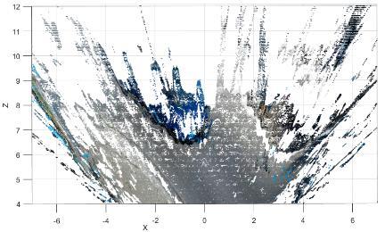
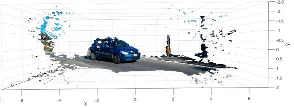
80 Figure 13. Measurement of the heading of the OV. Figure 14. Measurement of two vehicles. Savino 11


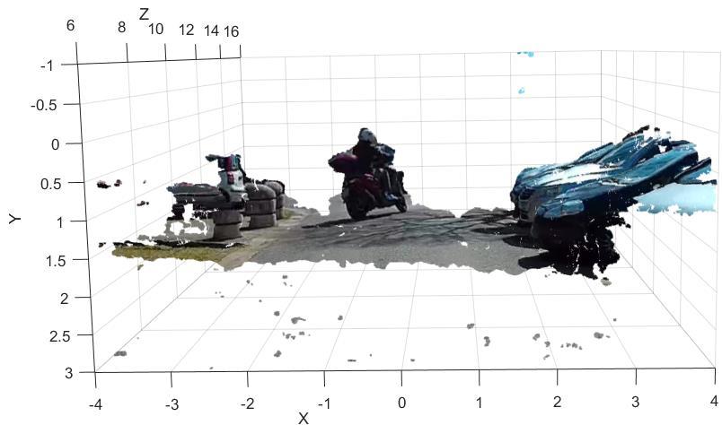
81 Figure 15. Heading of big obstacles. Figure 16. Measurement of other PTW entering traffic. Savino 12
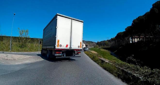

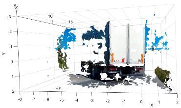
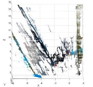
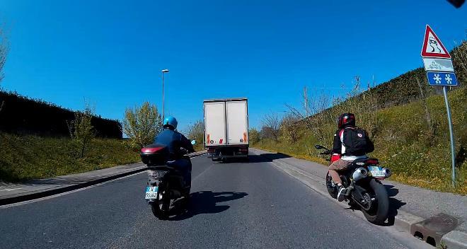

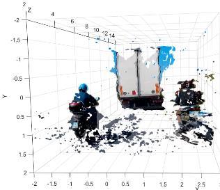
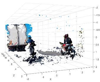
82 Figure 17. Measurement of a large obstacle. Figure 18. Measurement of two narrow objects. Savino 13
83 SECOND GENERATION AACN INJURY SEVERITY PREDICTION ALGORITHM: DEVELOPMENT AND REAL-WORLD VALIDATION Stewart C. Wang, MD, PhD Carla J. Kohoyda-Inglis, MPA Susumu Ejima, PhD Joel B. MacWilliams Peng Zhang, PhD University of Michigan International Center for Automotive Medicine USA Lisa Stacey Anthony Melocchi David Gorman Jiri Kral, PhD General Motors Corporation USA Jeffery W. Joyner OnStar USA Paper Number ABSTRACT Advanced automatic collision notification (AACN) based injury severity prediction (ISP) has great potential to improve post-crash care. The national Expert Panel for Field Triage set 20% risk of Injury Severity Score (ISS) 15+ injury as the threshold for urgent transport to a trauma center. Earlier, we published an Injury Severity Prediction algorithm (ISP v1) that was developed using data from the National Automotive Sampling System Crashworthiness Data System (NASS_CDS) for the calendar years In a field trial published at ESV 2015, this ISP algorithm version 1 demonstrated better than predicted sensitivity to detect seriously injured (ISS15+) crash occupants. In the current study, we sought to a) update the ISP algorithm using more current NASS-CDS data, b) improve predictive accuracy by refining the granularity of the input data, and c) validate the ability of this updated algorithm (ISP v2) using real-world crash cases involving GM vehicles equipped with OnStar. NASS-CDS data ( ) was used to develop a functional logistic regression model to predict the probability that a crash-involved vehicle would contain one or more occupants with ISS 15+ injuries in planar, non-rollover crash events involving Model Year 2000 and newer cars, light trucks, and vans. Two of the parameters used in the original ISP algorithm were modified (principal direction of force [PDOF], older occupant age) and a new parameter was created and involved the presence of a right-sided passenger. This study was approved by the IRB of the Michigan Department of Health and Human Services (formerly the Michigan Department of Community Health). The initial 924 occupants in 836 crashes published in the 2015 study were again opened for review and injury severity predictions from the updated algorithm were compared to the observed injury outcomes. The updated ISP v2, which employs the functional data analysis technique to model the effect of PDOF to ISS 15+ injury as a continuous cyclic function, showed an improved predictive performance (AUC 0.872, AIC 2370) over the original ISP v1 (AUC 0.865, AIC 2377) that used only 4 crash directions. The original elderly age cutoff of 55 performed better than an age cutoff of 60, so age 55 was retained as a parameter in ISP v2. Using field data for validation, the updated ISP algorithm had significantly improved sensitivity for detecting seriously injured (ISS 15+) occupants (72.7% vs. 63.4%) with minimal changes in specificity (93% vs 94%). The AUROC for ISP v2 was 0.946, an improvement over the AUROC for ISP v1 (AUROC 0.932). This study confirms under real world field conditions that occupant injury severity can be predicted using vehicle telemetry data. The updated ISP v2 algorithm s ability to predict a 20% or greater risk of severe (ISS15+) injury confirms ISP s utility for the field triage of crash subjects. Wang 1
84 INTRODUCTION According to the Centers for Disease Control (CDC), in ,412,109 occupants were injured and 33,736 occupants were killed in motor vehicle crashes in the US alone. [4] Numbers are higher across the globe, with the World Health Organization (WHO) stating up to 50 million people are injured and over 1.2 million people killed in MVCs.[5] It appears there is still much work to be done to decrease these numbers. Minimizing the time between injury and treatment is vitally important to reduce morbidity and mortality. First responders must arrive at the scene quickly, with appropriate equipment, to treat, triage, and transport occupants to the appropriate medical center for further care. There is a 25% reduction in mortality if occupants arrived at a Level I Trauma center versus a non-trauma center. [6] The CDC s National Expert Panel concluded that AACN showed promise in improving outcomes to severely injured crash patients by: Predicting the likelihood of serious injury in vehicle occupants Decreasing response times by pre-hospital care providers Assisting with field triage destination and transportation decisions Decreasing time to definite trauma care Decreasing death and disability from MVCs This panel recommended that pilot studies be conducted using vehicle telemetry data including: Delta V (crash severity) PDOF Seatbelt usage Crashes with multiple impacts Vehicle type Additionally, the panel recommended that voice communication be established to determine the presence of injuries and also to collect additional information that might affect injury risk. It endorsed calculating the injury risk with all available data and that if the occupant is at 20% or greater risk of ISS 15+ injury, the relevant Public Safety Answering Point (PSAP) should be notified that the occupant meets the Field Triage Decision Scheme s Step 3 criterion for vehicle telemetry consistent with high risk of injury and appropriate resources dispatched. [1] With these recommendations in mind, the first ISP algorithm was developed using a logistic regression model of national representative crash data (NASS- CDS, calendar years ). [2] This dataset provided a model sensitivity of 40% and specificity was 98% using an injury probability cutoff of 20% risk of ISS >15. In a field trial published at ESV 2015, this ISP algorithm version 1 demonstrated better than predicted sensitivity to detect seriously injured (ISS15+) crash occupants. [3] In a field trial published at ESV 2015, this ISP algorithm version 1 demonstrated better than predicted sensitivity to detect seriously injured (ISS 15+) crash occupants. [3] In the current study, we sought to a) update the ISP algorithm using more current NASS-CDS data, b) improve predictive accuracy by refining the granularity of the input data, and c) validate the ability of this updated algorithm (ISP v2) using realworld crash cases involving GM vehicles equipped with OnStar. METHODS NASS-CDS data ( ) was used to develop a functional logistic regression model to predict the probability that a crash-involved vehicle would contain one or more occupants with ISS15+ injuries in planar, non-rollover crash events involving Model Year 2000 and newer cars, light trucks, and vans. Unchanged model input parameters from ISP v1 included: change in velocity (Delta-V), multiple vs. single impacts, belt use, presence of a female occupant, presence of an older occupant ( 55 years of age), and vehicle type (car, pickup truck, van, and sport utility). Two of the parameters were modified to address opportunities noted in results from the field trial of ISP v1. Modified input parameters included: PDOF as a continuous input, ranging from 0 to 360 degrees (instead of 4 crash directions: front, left, right, and rear) and the presence of an older occupant ( 55 years old vs. 60 years old). To investigate PDOF as the actual degrees rather than direction categorization, we used a functional data analysis approach and modelled the logarithm of the relative odds of PDOF on injury risk as a continuous cyclic function ranging from 0 to 360 degree. The function was modelled as cyclic basis splines with 10 degrees of freedom. There was discussion regarding the original age cut off of >55 years. We divided occupants with a series of different age cutoffs, ranging from 40 to 70 years. Wang 2
85 For each age cutoff, we compared the risk of having an ISS 15+ injury between two groups and calculated p-values. Figure 1 shows the logarithm of p values versus age cutoffs. P-values steadily decrease until approximately the age of 60. In developing ISP v2, we investigated whether choosing an older age cutoff would improve the prediction accuracy. Figure 1: Age cutoffs and logarithm of p values. A new input parameter included presence of a rightsided passenger and its interaction with PDOF. When a right-side passenger is present, another functional curve of PDOF was added to the model. This represents the additive injury risk due to the rightside passenger. The logarithm of relative odds of PDOF for this injury risk was modelled as cyclic basis splines with 5 degrees of freedom. Finally, in developing ISP v2, we employed a forward/backward selection procedure. Starting from the null model, in each step, we added or removed one variable to minimize Akaike Information Criterion (AIC). The procedure stops when AIC cannot be improved and the final model is then reported. 924 occupants in 836 crash events involving vehicles equipped with AACN capabilities in the state of Michigan were identified from the OnStar records. The injury status of all occupants in the case vehicles was determined. The updated algorithm (ISP v2) was used to calculate the predicted risk of injury based on transmitted telemetry data and this prediction was compared to the observed injury outcome. RESULTS We compared the predicted versus observed injuries for four different models: ISP v1 refitted with NASS-CDS data through year 2013 ISP v1 refitted, but using the age cutoff as 60 ISP v2 with inputs as logarithm of Delta V, 10 cyclic basis splines for PDOF, 5 cyclic basis splines for PDOF when right-side passenger is present, belt status, vehicle body type, if multiple events, if age is equal to or older than 55, gender Same as ISP v2, but use if age is equal to or older than 60 Table 1. Coefficients Est SE P values Intercept <0.001 ln delta-v (mph) <0.001 If all occupants belted <0.001 If at least one occupant > <0.001 If a multiple event If at least one female PDOF (splines with df = 10) main effect PDOF (splines with df = 5) when there is also a RFP < Wang 3
86 Table 2. The performance of the four statistical models using NASS data. AIC AUC ISP v ISP v1 (Age cutoff: 60) ISP v ISP v2 (Age cutoff: 60) Note that smaller AIC results in better fit of data, while a larger AUC indicates better predictive ability of the models. Consistently, seen from both AIC and AUC, ISP v2 performs better than ISP v1. Choosing age cutoff as 60, identified through univariate analysis, actually leads to worse results in the multivariate analysis. We therefore chose model 3 above (i.e. ISP v2 with age cutoff of 55) as the final model. The functional curves of relative odds of severe injury for the full range of PDOF are presented in Figure 2. We chose 0 degree PDOF as the reference point, and plotted the relative odds of PDOF for drivers (left) and right-side passengers (right). For drivers, the relative odds increased to 4 as PDOF increased to 90 degrees. The increase of odds seems not linear and more dramatic after 45 degrees. This somewhat suggests a smaller window for side-impact injury risk. The relative odds then decreased to ~ 0.5 when PDOF was close to 180 degrees. From there, the relative odds increased to about 12 when PDOF was close to 270 and dropped back to 1 when PDOF reached 360. Driver Right-side Passenger Wang 4
87 When there is a right-side passenger, the additive relative odds of ISS 15+ injury peaked at 3.8 when PDOF was near 90 degrees. There is a smaller peak of relative odds at 1.5 when the impact came from the left side. Interestingly, the PDOF corresponding to this peak is not at 270 degrees, but closer to 315 degrees, which is a left, frontal impact. We validated the new developed model with the OnStar data used in our 2015 ESV study. Our OnStar dataset has 924 occupants in total, and represents a slightly different population than NASS-CDS from which the predictive model was developed. The median age in OnStar is 41 years old. 57% are female. 21% are right-side passengers. Only 1.2% of occupants have ISS 15+ injury. We included rear seat passengers in this study of occupant outcomes (rear seat passengers were not considered when developing the predictive model). DISCUSSION The Injury Severity Prediction algorithm was updated using current NASS-CDS data. This updated algorithm (ISP v2) with PDOF included as a continuous input rather than four discrete crash directions shows significantly improved sensitivity to detect seriously injured (ISS 15+) occupants, whether drivers or right-sided passengers. The field performance of ISP v2 utilizing the OnStar dataset showed 72.7% sensitivity and 93% specificity. Sensitivity is defined as the probability that a test result will be positive (ISP 0.2) when the condition (ISS 15+) is present. The observed sensitivity performance was better than the 40% performance that ISP v1 achieved when applied to the NASS-CDS dataset and better than the 63.4% performance that ISP v1 achieved when applied to the same field cases. As previously stated, the more Figure 2: Functional curves of relative odds of severe injury for the full range of PDOF. The updated ISP v2, which employs the functional data analysis technique to model the effect of PDOF to ISS 15+ injury as a continuous cyclic function, showed an improved predictive performance (AUC 0.872, AIC 2370) over the original ISP v1 (AUC 0.865, AIC 2377) that used only 4 crash directions. The original elderly age cutoff of 55 performed better than an age cutoff of 60, so age 55 was retained as a parameter in ISP v2. Using field data for validation, the updated ISP algorithm had significantly improved sensitivity for detecting seriously injured (ISS 15+) occupants (72.7% vs. 63.4%) with minimal changes in specificity (93% vs 94%). The AUROC for ISP v2 was 0.946, an improvement over the AUROC for ISP v1 (AUROC 0.932). Table 3: ISP v1 Sensitivity and Specificity Sensitivity: 63.4% Specificity: 94% Table 4: ISP v2 Sensitivity and Specificity Sensitivity: 72.7% Specificity: 93% consistent and accurate measurements of crash severity, more accurate determination of restraint use, and more consistent vehicle safety performance due to the vehicles being from a single manufacturer and being newer models may play a part in the better performance of the algorithm. The specificity performance of the ISP in this study was 93%. Specificity is defined as the probability that a test result will be negative (ISP<0.2) when the condition (ISS>15) is not present. The observed specificity performance was less than the 98% performance that the algorithm achieved when applied to the NASS-CDS dataset and slightly less than ISP v1 specificity of 94% when applied to the field cases. While the overall number of cases studied is relatively small, there were fewer ISS>15 injured cases observed than would have been expected based on the number of cases, configuration and crashseverity mix of the crashes included in this study. This trend might be the result of continuously improving vehicle safety performance in the study fleet versus the NASS-CDS fleet used to calibrate the algorithm. The average age of the study fleet was younger than the average age of the vehicles in NASS-CDS. [3] ISP v1 was developed from NASS-CDS data and defined crash direction into only four categories (front, left, right, and rear). Real world crashes cannot always fit into these groups and frequently fall into offset or narrow configurations that may impact injury risk. Right side and oblique impact crashes appear to be underweighted in ISP v1. In the 2015 Wang 5
88 field trial, observed injuries of right sided occupants suggested that it could be beneficial to adjust the right side impact coefficients to reflect a higher risk of severe injury if there is a right sided occupant in place during the crash. In the current study, we modified the ISP algorithm to utilize crash PDOF as the actual degrees rather than 4 simple direction categories. We used a functional data analysis approach and modelled the logarithm of the relative odds of PDOF on injury risk as a continuous cyclic function ranging from 0 to 360 degree. The function was modelled as cyclic basis splines with 10 degrees of freedom. A new input parameter included presence of a right-sided passenger and its interaction with PDOF. When a right-side passenger is present, another functional curve of PDOF was added to the model. This represents the additive injury risk due to the rightside passenger. The logarithm of relative odds of PDOF for this injury risk was modelled as cyclic basis splines with 5 degrees of freedom. Examination of the OnStar cases used for validation showed improved injury prediction of right-sided crashes. The theory that the ISP could be better improved with more granular age parameters rather than a single threshold of age 55 proved to be false. We divided occupants with a series of different age cutoffs, ranging from years. For each age cutoff, we compared the risk of having an ISS 15+ injury between two groups. Choosing the age cutoff as 60 actually led to worse results in the multivariate analysis. While it is well known that the increased crash injury risk accelerates with advancing age rather than plateauing, [6-9], in this analysis a cutoff of age 55 resulted in a better fit and better predictive ability for the algorithm. The Sensing and Diagnostic Module (SDM) does not have the capability to capture age data. When the telematics provider contacts the occupants in the crashed vehicle, they ask questions about who is in the vehicle. In this way, they can obtain age to send to the PSAPs. These results confirm the importance of age in injury risk calculation and highlight the importance of collecting this data. Finally, in developing ISP v2, we employed a forward/backward selection procedure. Starting from the null model, in each step, we added or removed one variable to minimize Akaike Information Criterion (AIC). The procedure stops when AIC cannot be improved and the final model is then reported. We believe this to be a more consistent approach that can be used for future ISP iterations. CONCLUSION As with ISP v1 and the subsequent field trial, this study confirms under real world field conditions that occupant injury severity can be predicted using vehicle telemetry data. The updated ISP v2 algorithm s ability to predict a 20% or greater risk of severe (ISS 15+) injury confirms ISP s utility for the field triage of crash subjects. The level of sensitivity for severe injury achieved by ISP v2 increased to a remarkable 72.7 achieved with only data or communication transmitted from the vehicle and before dispatch of EMS to the scene. Since the consequence of missing a severe injury is immediately life-threatening, sensitivity receives the highest priority in trauma care. The longstanding Field Decision Scheme has been used as the basis for triage protocols in state and local emergency medical systems (EMS) across the United States for many decades. The combined sensitivity of the first two steps (Physiologic and Anatomic) of the Decision Scheme has consistently remained ~ 40-50% with field data collected by first responders. [12-15] Newer crash sensors may also support further improvements in the performance of the ISP algorithm. As the SDM systems change and more detailed telemetry data collection is possible, ICAM anticipates improvements in risk prediction. The fleet is in constant flux with new safety systems as well as enhanced SDMs. [16, 17] Michigan, parts of the United States, and the world all have many rural areas where reports of crash events to public safety may be delayed, leading to slow response by EMS. [18, 19] These same areas are also characterized by long transport distances that will delay the transfer of the severely injured to medical facilities. Automatic collisions notification alone, without additional vehicle telemetry for injury prediction, can save significant lives [20]. Time is of the essence in these cases and getting these occupants to the proper medical destination capable of definitive trauma care is essential. Transmitted telemetry data from AACN can not only provide notification that a crash has occurred, it can also alert the local first responders as to what type and how severe of crash they are responding to they will know what equipment to bring in order to best triage and treat the occupants. There is potential also to immediately initiate air transport and get them to the scene quickly as well. The resources utilized in the emergency care of crash Wang 6
89 injuries place a significant burden on local communities, especially rural ones. Over triaging patients without severe injuries to trauma centers or other medical centers for unnecessary evaluation is expensive and wasteful. The recent changes to Step 3 (mechanism of injury) of the Field Triage Decision Scheme is estimated to provide yearly US savings of over $500 million in medical costs alone. [21] With widespread use of AACN, those savings can be multiplied. [3] BIBLIOGRAPHY [1] Sasser, S.M., Hunt, R.C., et al. Guidelines for field triage of injured patients. Recommendations of the National Expert Panel on Field Triage. MMWR Recomm Rep, (RR-1): p [2] Kononen, D.W., Flannagan, C.A.C., and Wang, S.C. Identification and validation of a logistic regression model for predicting serious injuries associated with motor vehicle crashes. Accident Analysis & Prevention, (1): p [3] Wang, S.C., Kohoyda-Inglis, C.J., et al. Results of First Field Test of Telemetry Based Injury Severity Prediction, in 24th International Technical Conference on the Enhanced Safety of Vehicles (ESV): Traffic Safety Through Integrated Technologies. 2015, National Highway Traffic Safety Administration: Gothenburg, Sweden. p. 12. [4] CDC. "Injury Prevention and Control: Data and Statistics (WISQARS)" Internet ml. [cited 2016 December 13]. [5] WHO. Global Status Report on Road Safety , World Health Organization: Geneva, Switzerland. p [6] MacKenzie, E.J., Rivara, F.P., et al. A national evaluation of the effect of trauma-center care on mortality. N Engl J Med, (4): p [7] Champion, H.R., Copes, W.S., et al. The Major Trauma Outcome Study: establishing national norms for trauma care. J Trauma, (11): p [8] Grossman, M.D., Miller, D., Scaff, D.W., and Arcona, S. When is an elder old? Effect of preexisting conditions on mortality in geriatric trauma. J Trauma, (2): p [9] Morris, J.A., Jr., MacKenzie, E.J., and Edelstein, S.L. The effect of preexisting conditions on mortality in trauma patients. JAMA, (14): p Wang 7
90 PEER REVIEW PAPER This paper has been peer reviewed and published in a special edition of Traffic Injury Prevention 18(S1), by Taylor & Francis Group. The complete paper will be available on the Traffic Injury Prevention and websites on June 5, To access all Peer-reviewed papers please copy and paste the link below into your browser to access the papers.
91 PREDICTING SEVERE INJURY IN MOTOR VEHICLE CRASHES Jacob Enriquez Ellen Lee National Highway Traffic Safety Administration U.S.A. Paper Number ABSTRACT Research Question/Objective: The National Highway Traffic Safety Administration (NHTSA) is actively studying the implementation of Advanced Automatic Collision Notification (AACN) systems in motor vehicles. This technology allows motor vehicles to notify a Public Safety Answering Point (PSAP), such as a 911 call center, in the event of a severe crash. The system provides crash location, vehicle identification information, as well as a prediction of severe injury to occupants in the motor vehicle. This paper describes the development of a statistical model that predicts the presence of severely injured and fatal occupants in a motor vehicle involved in a crash. Methods and Data Source: A logistic regression model was developed using data from the Crashworthiness Data System (CDS) of the National Automotive Sampling System (NASS). The binary response variable indicates whether or not a crashed vehicle contains a severely injured occupant or a fatally injured occupant, defined by an Injury Severity Score (ISS) of 16 or greater. The predictors are those recommended by the Centers for Disease Control and Prevention (CDC) National Expert Panel on Field Triage, which are delta-v, vehicle body type, multiple vs. single impact, seat belt usage, and principal direction of force. The final dataset is at the vehicle level. Results: The area under the receiver operator characteristic curve (AUC) was 0.843, indicating that the model was able to discriminate between vehicles with and without severely injured occupants. At the CDC recommended 0.20 risk threshold, the model produced a sensitivity rate of 26%, a specificity rate of 99%, and identified 41% of vehicles with a fatally injured occupant. Conclusion: The sensitivity rate at the CDC recommended 0.20 risk threshold missed 59% of vehicles with a fatally injured occupant. A preliminary cost-benefit analysis showed that the optimal threshold was close to after considering the cost of lives saved versus the cost of overtriaging minor injured people using the AACN algorithm. At the threshold, 92% of fatal occupants are predicted, the sensitivity is 91%, and the specificity is 60%, which comes close to the recommended levels by the American College of Surgeons. Limitations: An AACN system uses data from the event data recorder (EDR) of a vehicle; however, the model developed in this paper was trained with data collected from crash investigations, which may differ from EDR data. Also, this paper only considered the logistic regression model, whereas other data mining classifiers which may produce better results. The initial set of predictors was limited to those selected by the CDC Expert Panel. Enriquez, 1
92 INTRODUCTION In the event of a crash, an Advanced Automatic Collision Notification (AACN) system makes an emergency wireless call to a telematics service provider to send the vehicle s GPS location and crash-related data, and establishes a voice communications channel to the emergency call center. AACN differs from its predecessor, the Automatic Collision Notification (ACN) by including crash severity data as well as a prediction of severe injury. The prediction of severe injury is recommended to be used as part of the Emergency Medical Services (EMS) triage protocol (National Center for Injury Prevention and Control, 2008) to determine which facility to transport an injured patient to (e.g. a local hospital or a trauma center that has additional experience and equipment for treating severely injured people). The purpose of this paper is to develop a logistic regression model that predicts the presence of severely injured and fatal occupants in a crashed motor vehicle. Published injury severity predictive algorithms were examined in preparation for this paper: an algorithm developed by Kononen et al. (2011) for GM OnStar, an algorithm developed by Bahouth et al. (2012) for BMW, and an algorithm developed by Stitzel et al. (2016) for Toyota. Similar to the model developed by Kononen et al. (2011), the model developed for this paper follows the approach laid out by the Centers for Disease Control and Prevention (CDC) Expert Panel on Field Triage. In 2008, CDC assembled a panel of experts from various fields such as emergency medicine, trauma surgery, public health, vehicle telematics, and vehicle safety. The panel s purpose was to develop a medical protocol for utilization of AACN data from crashes to better predict severity of injury and use this information to improve the ability to respond to crashes and appropriately triage crash victims. They made several recommendations including a list of predictor variables, criteria for severe injury, and a choice of risk threshold. We used these recommendations as a starting point in this study, and performed tests to assess their validity. DATA The predictive model was developed using the Crashworthiness Data System (CDS). It is the only source of data that provides detailed information on injuries as well as crash severity. CDS is a nationally representative probability sample survey whose target population is police reported motor vehicle crashes on a trafficway involving at least one passenger car, pickup, van, or SUV that was towed from the scene due to damage. Crash investigators visit an annual sample of about 5,000 crashes to conduct a vehicle and scene inspection. The CDS three stage sample design and weight computation are described by Zhang and Chen (2013). This study used CDS years and applied the following filter criteria: 1. Passenger vehicles only (passenger cars, SUVs, vans, and pickups). 2. Deformation locations are front, right, left, and back only (no top or under). 3. Direction of force is between impact points 1 o'clock and 12 o'clock. 4. Vehicle model years Front row passengers only. 6. Passenger ages Planar crashes (no rollovers). In addition to these filters, each record (vehicle) must also meet the crash conditions required for the AACN system to make a notification call. Kononen et al. (2011) used the condition of delta-v 15 mph or airbag deployment, which is also applied in this study. After removing observations with missing data, the final data set has 13,146 records, with a weighted total of 4,206,182. Each record represents a vehicle. Response variable The binary response variable, y i, indicates whether or not a crashed vehicle contains a severely injured occupant or a fatally injured occupant. A value of 1 was assigned to a vehicle if any of its occupants experienced an Injury Severity Score (ISS) of 16 or higher, and zero otherwise. The weighted rate of occurrence of severe injury is 2% (Table 1). 1, if any occupant with ISS 16 y i = { } 0, otherwise An ISS of 16 or greater was used to indicate severe injury and is an anatomic scoring system based on the individual s three highest Abbreviated Injury Scale (AIS) values in different body regions. This was the outcome of interest specified by the 2008 CDC Expert Panel, when they defined severe injury in the context of vehicle telematics. The American College of Surgeons (ACS) periodically publishes a document titled Resources for Optimal Care of the Injured Patient, which represents the ACS Committee on Trauma s guidelines and recommendations for all aspects of trauma care, including pre-hospital care. In the 2014 version, the Enriquez, 2
93 ACS also recommended an ISS of 16+ be used to define major trauma patients. Therefore, this paper focuses on ISS of 16 or greater as the indicator for severe injury. Table 1 Distribution of the Response Variable y i Frequency Weighted Percent Frequency 0 11,984 4,123, ,162 82,194 2 Total 13,146 4,206, VARIABLE SELECTION An important step in building a statistical model is determining which variables should be included in the model. For this study, the initial set of predictors were those recommended by the CDC Expert Panel (Table 2). These variables can be electronically transmitted by the vehicle to the AACN providers in the event of a crash. Table 2. Selected Predictors and Their Descriptions Variable Type Values Description name LN_DVMPH Continuous Change in the vehicle velocity. Log of delta-v. DOF1 Categorical Front, Left, Direction of force. Right, Rear CBELT Categorical Yes, No Seat belt usage. Yes = all occupants belted. No = at least one occupant BODY Categorical Car, SUV, Pickup, Passenger van ACCSEQ Categorical Multiple, Single unbelted. Type of vehicle. Number of significant impacts to a vehicle. Note: The variable names are specific to this study and are not the same as in CDS. A univariate analysis was conducted to determine whether each predictor is "significantly" related to the response variable. This was done using the likelihood ratio chi-squared test and the Wald test. The likelihood ratio chi-squared test was used to test the null hypothesis of statistical independence between the response variable and each predictor. The p-value for this test is less than for each predictor (Table 3), which provides evidence of an association. The large chi-squared statistics may be heavily influenced by the large weighted sample size. Table 3. Likelihood Ratio Chi-Square Test Predictor Likelihood DF Probability Ratio Chi- Square Statistic ACCSEQ 12,384 1 < BODY 6,257 3 < CBELT 31,948 1 < DOF1 27,091 3 < LN_DVMPH 131,696 1 < A univariate logistic regression model was fit for each predictor to test for the significance of the coefficient using the Wald Chi-Square test statistic, W = (β β 1 ) 2 Var (β ) Under the null hypothesis that β 1 is equal to zero, the statistic W follows a chi-square distribution with 1 degree of freedom. All the predictors and their design variables had p-values less than 0.05, except for the Pickups design variable for the predictor BODY (vehicle body type). It had a p-value of (Table 4). However, the Type 3 multivariate Wald test for the BODY variable, which tests all its design variables simultaneously, has a p-value of < Table 4. Wald Chi-Square Test for the BODY Variable Param DF Est. Std Err Wald Chi-Sq Pr > ChiSq Intercept <.0001 BODY (Pickups) BODY <.0001 (SUV) BODY (Vans) Enriquez, 3
94 In addition to the univariate analysis, a stepwise procedure was conducted. This procedure systematically checks for the importance of variables, and either includes or excludes them in the model depending on a decision rule. The procedure starts off with no predictors in the model. In each step, the predictor with the largest Score chi-square statistic that meets the p < 0.01 level is included in the model; while the predictor considered least significant according to the Wald test and does not meet the p < 0.01 level is removed from the model. The process terminates if no further predictor can be added or if the current model is identical to a previously visited model. Results of this method (Table 5) show that all predictors entered the model, and none were removed. The first variable to enter was delta-v and the last to enter was ACCSEQ (number of impacts to a vehicle). The large Score test statistic values may be heavily influenced by the large weighted sample size. Table 5. Summary of Stepwise Selection Step Var Entered Var Removed DF Score Chi-Sq Pr>Chi Sq 1 LN_DVMPH ,576 < DOF1-3 37,454 < CBELT ,650 < BODY - 3 4,913 < ACCSEQ - 1 4,880 <.0001 Results from the likelihood ratio chi-square test, the Wald test, and stepwise procedure show that it is reasonable to use all the CDC recommended predictors for the multivariate model. MODELING Logistic regression was used to estimate the probability that a crashed vehicle contained a seriously injured or fatal occupant, conditional on the values of the predictor variables. The logistic regression model is, P(Y = 1 x) = eβ 0+ β1x1+β2x2+ +βpxp 1+e β 0+ β1x1+β2x2+ +βpxp, Eq. (1) where p = 9 (total predictor variables), x = (x 1, x 2,, x p ) is a vector of predictor variables, and β 0,, β p are parameters. There are now nine independent variables instead of the initial five since design variables were created for the BODY (vehicle body type) and DOF1 (direction of force) variables. The model was fit using the maximum likelihood method, which produces an estimate for the parameters that maximizes the probability of obtaining the observed set of data. The SURVEYLOGISTIC procedure in SAS was used to incorporate the CDS survey design by specifying the primary sampling unit (PSU), the PSU stratum, and weight variables. Results of fitting the multiple logistic regression model are given in Table 6. Testing for the significance of the model To assess the overall significance of the coefficients for the predictor variables in the model, the likelihood ratio test was used with the null hypothesis that all coefficients in the model are equal to zero. The p-value for the test is < (Table 7), rejecting the null hypothesis, and conclude that at least one coefficient was different from zero. Table 6. Maximum Likelihood Estimates Parameter DF Estimate Std. Error Wald Chi- Square Pr > ChiSq Standardized Estimate 95% Confidence Limits Intercept <.0001 ( , ) ACCSEQ Multiple (0.1993, ) BODY Pickups ( , ) BODY SUV ( , ) BODY Vans ( , ) CBELT All Belted < ( , ) DOF1 Front (0.2749, ) DOF1 Left < (1.7897, ) DOF1 Right < (0.9905, ) LN_DVMPH < (3.0416, Note: The column between Parameter and DF specifies the comparison group. For example, Multiple is indicated for the variable ACCSEQ because the estimate corresponds to that of multiple event crashes in reference to single event crashes. Enriquez, 4
95 Table 7. Testing Global Null Hypothesis: Beta=0 Likelihood Ratio Test DF Pr > ChiSq 201, <.0001 The Vans design variable for BODY (vehicle body type) is not significant with a p-value greater than 0.05 for the univariate Wald test, and a confidence interval that includes zero (Table 6). However, the Type 3 multivariate Wald test, which tests the null hypothesis that all the coefficients of the design variables for BODY are simultaneously zero, has a p- value of < (Table 8). Hence the BODY variable is not excluded from the model. Table 8. Type 3 Analysis of Effects Effect DF Wald Chi-Sq Pr > ChiSq ACCSEQ BODY <.0001 CBELT <.0001 DOF <.0001 LN_DVMPH <.0001 Ranking the predictors A standardized coefficient indicates how many standard deviations of change in the respondent variable are associated with a one standard deviation increase in the predictor variable. Shown in the 8 th column of Table 6, the highest standardized coefficient (absolute value) belongs to the LN_DVMPH (log of delta-v) predictor followed by CBELT (all occupants belted or not) and the DOF1 (direction of force) design variables. The lowest standard coefficient belongs to the BODY (vehicle body type) design variables and ACCSEQ (number of significant impacts to the vehicle). This coincides with the order in which the variables entered the stepwise method (Table 5). Interaction effects Two-way interaction effects were entered into the main effects model, one at a time, and checked for statistical significance. All interaction effects either had p-values > 0.05 for the univariate Wald test, or did not make scientific sense. Hence no interactions terms were included in the model. Distribution of the estimated probabilities The estimated probabilities produced by the model are very low, with a median of only (Table 9). This is due to the rarity of the occurrence of severe injury, with only 2% of the vehicles having at least one occupant with an ISS of 16 or greater (Table 1). Table 9. Weighted Quantiles of the Estimated Probabilities Quantile Estimate 100% Max % % % % Q % Median % Q % % % % Min ASESSING THE PREDICTIVE ACCURACY OF THE MODEL To assess the predictive accuracy of the model, the k- fold cross-validation method was used. In this method the data was split into k = 10 equal-sized subsets. One of the subsets was chosen for testing the model, while the remaining nine subsets were used for training the model. This was repeated k = 10 times so that each record was used for training exactly nine times and testing exactly once. The resulting estimated probability of each record was used to assess the discrimination and accuracy of the model. Area under the curve Discrimination refers to the model s ability to distinguish low from high risk vehicles. This means vehicles with y = 1 should have higher probability estimates than vehicles with y = 0. Discrimination can be quantified by the area under the receiver operating characteristic curve (AUC), which is a curve constructed by plotting sensitivity against 1- specificity for different cut-offs. An intuitive explanation of the AUC is that if each vehicle with y = 1 is paired with each vehicle with y = 0, then the AUC is the proportion of the pairings where the vehicle with y = 1 has a higher estimated probability than the vehicle with y = 0. The AUC for this model is 0.843, which is considered excellent discrimination according to Hosmer and Lemeshow (2000). Classification table A classification table cross-classifies the binary response variable with the prediction of the model (1 or 0). The estimated probabilities are converted to predictions by first selecting some risk threshold, t, where 0 < t < 1 (statistical texts refer to this as the cutpoint or the cut-off). If the estimated probability Enriquez, 5
96 is greater than or equal to t, then set the prediction equal to 1; otherwise set the prediction equal to 0. Table 10 shows the classification table, with weighted counts, for a threshold of 0.20, which is the recommended threshold by the CDC Expert Panel. The overall rate of correct classification is estimated as (4,093, ,688)/ 4,206,182 = 98%, with 26% (21,688/82,194) of the y = 1 group (sensitivity) and 99% (4,093,805/4,123,989) of the y = 0 group (specificity) being correctly classified. Table 10. Classification Table (Weighted) Using a Threshold of Response Predicted 0 1 Total 0 4,093,805 60,506 4,154, ,184 21,688 51,872 Total 4,123,989 82,194 4,206,182 Aside from sensitivity and specificity, the model was also assessed in how well it identified vehicles with a fatally injured occupant, referred to as fatal vehicles. Fatal vehicles are a subset of the y = 1 group, and should have a prediction of 1. The proportion of fatal vehicles identified by the model (having a predicted value of 1) was 41%, using the 0.20 threshold. Figure 1 plots the sensitivity, specificity, and percent of fatal vehicles identified by the model at different thresholds. Relating sensitivity and specificity to undertriage and overtriage, and their recommended levels The 2014 edition of the American College of Surgeons (ACS) Resources for Optimal Care defines undertriage as severely injured patients transported to lower-level trauma centers or other facilities, and overtriage as minimally injured patients transported to higher-level trauma centers. The ACS gives higher priority to reduction of undertriage, because undertriage may result in preventable mortality or morbidity from delays in definitive care. The recommended level for undertriage is 5%. Overtriage may result in higher costs and also increase the burden for higher-level trauma centers because resources needed for more severely injured patients are unnecessarily being used for minimally injured patients. Acceptable rates for overtriage are in the range of 25-35% according to the ACS. In the context of the injury prediction algorithm developed here, the sensitivity of the algorithm is equal to 100% minus the undertriage rate (i.e. a sensitivity of 95% will result in 95% of seriously injured occupants being correctly identified as seriously injured, and 5% being undertriaged, or incorrectly identified as not seriously injured). Specificity, or the true negative rate (proportion of occupants with ISS < 16 who are correctly identified by the algorithm as having a low risk of injury), is Figure 1. Plot of Sensitivity, Specificity, and Percent Fatal Vehicles Identified by Threshold. Enriquez, 6
97 equal to 100% minus the overtriage rate. It is noteworthy that at the CDC recommended 0.20 risk threshold, the prediction algorithm falls far short of the recommended 5% undertriage rate (instead resulting in a 74% undertriage rate), while it far exceeds the recommendations for overtriage (predicting only 1% overtriage, rather than the ACS recommended 25-35%). In order to meet the 5% undertriage rate, the threshold needs to be lowered from the 0.20 threshold. As shown in Figure 1, lowering the threshold increases both sensitivity and percent of fatal vehicles identified, but it also lowers the specificity. Lowering the specificity is equivalent to increasing the rate of false positives (false alarms), which results in overtriage costs. Finding the right balance of increasing the percent of fatal vehicles identified by the model while minimizing the rate of false positives is addressed in the next section. FINDING AN OPTIMAL THRESHOLD As demonstrated above, at the CDC recommended 0.20 risk threshold, the prediction algorithm falls far short of the undertriage rates recommended by the ACS. To provide a basis for choosing an optimal threshold that deviates from the CDC recommendation, the costs of under- and overtriage were evaluated. For a preliminary determination of an ideal threshold for the model, the benefit of true positives was weighed against the cost of false positives at thresholds below The benefit of true positives is the economic savings from those that would have died but were saved due to AACN. The cost of false positives comes from overtriage, which is transporting occupants without serious injuries to major trauma centers. Benefits The benefits at a specific threshold is the number of lives saved by AACN multiplied by the dollar amount saved per fatality prevented. Lee et al. (2017) estimated the number of lives saved by AACN to be, at most, 721 per year. This number assumes the predictive model identifies 90% of the fatal occupants. This percentage is replaced with the appropriate percentage at each threshold. As for the economic savings, Blincoe et al. (2015) estimates the comprehensive fatality injury cost to be $9,129, This equals comprehensive costs less congestion costs and property damage costs. Comprehensive costs consist of tangible losses (such as property Since a fatality prevented by AACN cannot be considered to be uninjured, it is assumed that the saved occupant will still have a maximum AIS (MAIS) 4 injury level with a comprehensive injury cost of $2,414, The cost savings of preventing a fatality is the difference between these two injury costs which is $6,714,814. The benefit at a particular threshold, t, can now be expressed as, Benefit(t) = 721 %FatalsPred(t) $6,714, Costs The cost at a specific threshold is the number of minor injured occupants (ISS < 16) unnecessarily treated at a trauma center multiplied by the cost of overtriage per patient. The number of occupants with ISS < 16 is estimated to be around 4 million annually, using CDS Since not all of these occupants will be sent to a trauma center as a direct result of AACN, the following reduction factors were applied: 1. % overtriage NOT identified by steps 1 and 2 of the triage protocol = 78% % of occupants with ISS < 16 that were in a crashed vehicle that met the conditions for the AACN system to make a call (i.e. delta- V 15 or airbag deployment) = 60%. 3. % access to trauma center = 80% (NHTSA, 2012). Applying the reduction rates to the 4 million occupants produces 1,497,600 which is then applied the rate of false positives at a specific threshold. The rate of false positives is equal to one minus the specificity computed at the occupant level. The cost of minor injured occupants treated at a trauma center is approximately $5,000 - $10,000 according to Newgard et al. (2013) and Faul et al. (2012). Using the midpoint of this range, the cost at a particular threshold is, Cost(t) = 1,497,600 (1 specificity(t)) $7,500 Computed values for benefits, costs, and their difference are shown in Table 11 and plotted in Figure 2. At the CDC recommended threshold of 0.20, benefits exceed costs by about $2.18 billion. As the threshold is lowered, benefits continue to be damage, medical care, insurance costs, legal costs, etc.) plus costs associated with lost quality of life. 2 Newgard et al. (2011) and Brown et al. (2011) show 14% - 22% overtriage using just steps 1 and 2 of the triage protocol. Enriquez, 7
98 greater than costs. Around the 0.06 threshold, costs start to climb at a higher rate than benefits, and eventually the two become equal somewhere between the and thresholds. After this point costs exceed benefits. Since lowering the threshold results in more lives saved, then is the threshold where the maximum number of lives can be saved without costs exceeding benefits. This number seems to be the logical choice as the optimal threshold. At this threshold, 92% of fatal occupants are predicted, the sensitivity is 91% (undertriage rate of 9%), and the specificity is 60% (overtriage rate of 40%). These results are approximately consistent with the ACS recommended under- and overtriage levels of 5% and 25-35% respectively. The small threshold of may seem to suggest that the model will predict nearly all vehicles that meet the AACN crash criteria to have a severely injured occupant. This is not the case. According to the distribution of the estimated probabilities (Table 9), among vehicles that meet the AACN crash criteria, the proportion having an estimated probability greater than is around 40%. Although other published logistic regression models (e.g. Bahouth et al. 2012; Stitzel et al. 2015) did not consider the economic costs and benefits of underand overtriage, their optimal predictive performance occurred at thresholds lower than the CDC recommended 0.20, similar to the findings of the current study. CONCLUSION The purpose of this paper was to develop a logistic regression model that predicts the presence of severely injured and fatal occupants in a crashed motor vehicle. The model was trained using CDS data, accounting for its sample design. The binary response variable indicates whether or not a crashed vehicle contains a severely injured occupant or a fatally injured occupant. The predictors are those recommended by the CDC Expert Panel on Field Triage, which are delta-v, direction of force, vehicle body type, seat belt use, and number of crash events (multiple or single). The most significant predictor is delta-v followed by seat belt use and direction of force. At the CDC recommended threshold of 0.20, the model produces an AUC of 0.843, a sensitivity of 26%, a specificity of 99%, and predicts 41% of the fatal vehicles (Figure 1). Based on a preliminary cost-benefit analysis considering the cost of lives saved versus the cost of overtriaging minor injured people using the AACN algorithm, the study showed that the optimal threshold was close to At this threshold, 92% of fatal occupants are predicted, the sensitivity is 91%, and the specificity is 60%. LIMITATIONS AND FUTURE CONSIDERATIONS 1. An AACN system uses data from the event data recorder (EDR) of a vehicle. The model developed in this paper, as well as others, were not trained with EDR data but with data collected from crash investigations (CDS). There may be differences between these two data sources, particularly the WinSmash delta-v estimates in CDS that have been found to underestimate EDR delta-v by as much as 23%. This study attempted to use EDR data but found it to be quite incomplete. 2. This study only considered predictors recommended by the CDC Expert Panel. While these variables were approved by subject matters experts, this study did not consider all possible predictors in CDS and other data sets. 3. This paper only considered one statistical model, logistic regression, among many classifiers that may produce better results. Kusano and Gabler (2014) compared several competing classification algorithms for predicting injured occupants in vehicle crashes and concluded that logistic regression slightly outperformed the machine learning algorithms based on sensitivity and specificity of the models. Enriquez, 8
99 Table 11. Benefits and Costs at Different Threshold Levels Below 0.20 Threshold Specificity (occupants) % Fatals predicted Benefits Costs Benefits minus Costs (occupants) $5,379,312,104 $11,232,000,000 ($5,852,687,896) $5,043,416,563 $6,148,264,446 ($1,104,847,883) $4,998,535,709 $5,061,452,716 ($62,917,007) $4,938,578,607 $4,720,220,174 $218,358, $4,839,495,036 $4,254,452,851 $585,042, $4,635,224,187 $2,262,520,828 $2,372,703, $4,292,737,805 $1,579,995,498 $2,712,742, $4,128,026,556 $1,222,219,386 $2,905,807, $3,847,380,225 $902,317,804 $2,945,062, $3,706,736,390 $717,113,769 $2,989,622, $3,588,052,336 $608,160,059 $2,979,892, $3,445,146,443 $541,242,997 $2,903,903, $3,322,509,772 $454,586,639 $2,867,923, $3,170,754,006 $388,886,788 $2,781,867, $2,551,270,193 $185,916,103 $2,365,354, $2,264,466,194 $86,810,724 $2,177,655,470 Figure 2. Difference between benefits and costs by threshold levels. REFERENCES [1] Agresti, A Categorical Data Analysis, Second Edition, New York: John Wiley & Sons. [2] Bahouth, G., Digges, K. and Schulman, C Influence of injury risk thresholds on the performance of an algorithm to predict crashes with serious injuries. In Annals of Advances in Automotive Medicine/Annual Scientific Conference (Vol. 56, p. 223). Association for the Advancement of Automotive Medicine. Enriquez, 9
100 [3] Blincoe, L. J., Miller, T. R., Zaloshnja, E., and Lawrence, B. A May. The economic and societal impact of motor vehicle crashes, (Revised) (Report No. DOT HS ). Washington, DC: National Highway Traffic Safety Administration. [4] Brown, J.B., Stassen, N.A., Bankey, P.E., Sangosanya, A.T., Cheng, J.D. and Gestring, M.L Mechanism of injury and special consideration criteria still matter: an evaluation of the National Trauma Triage Protocol. Journal of Trauma and Acute Care Surgery, 70(1), pp [5] Faul M, Wald MM, Sullivent EE, Sasser SM, Kapil V, Lerner EB, Hunt RC Large cost savings realized from the 2006 Field Triage Guideline: reduction in overtriage in U.S. trauma centers. Prehosp Emerg Care 16: [6] Hastie, T., Tibshirani, R., Friedman, J. H The Elements of Statistical Learning: Data Mining, Inference, and Prediction. New York, Springer. [7] Hosmer, D. W., Jr. and Lemeshow, S Applied Logistic Regression, Second Edition, New York: John Wiley & Sons. [8] Kononen, D.W., Flannagan, C.A. and Wang, S.C Identification and validation of a logistic regression model for predicting serious injuries associated with motor vehicle crashes. Accident Analysis & Prevention,43(1), pp [9] Kusano, K., Gabler, H Comparison and Validation of Injury Risk Classifiers for Advanced Automated Crash Notification Systems. Traffic Injury Prevention , S126 S133. [10] Lee, E., Wu, J., Kang, T. and Craig, M Estimate of Safety Benefit with Full Implementation of Advanced Automatic Collision Notification. ESV (Enhanced Safety of Vehicles Conference). Detroit, USA. [11] National Center for Injury Prevention and Control Recommendations from the Expert Panel: Advanced Automatic Collision Notification and Triage of the Injured Patient. Atlanta (GA): Centers for Disease Control and Prevention. [12] Newgard, C.D., Zive, D., Holmes, J.F., Bulger, E.M., Staudenmayer, K., Liao, M., Rea, T., Hsia, R.Y., Wang, N.E., Fleischman, R. and Jui, J A multi-site assessment of the ACSCOT field triage decision scheme for identifying seriously injured children and adults. Journal of the American College of Surgeons, 213(6), p.709. [13] Newgard CD, Staudenmayer K, Hsia RY, Mann NC, Bulger EM, Holmes JF, et al. The cost of overtriage: more than one-third of low-risk injured patients were taken to major trauma centers. Health Aff (Millwood). 2013;32: doi: /hlthaff [14] NHTSA The association between crash proximity to level 1 and 2 trauma centers and crash scene mortality of drivers injured in fatal crashes. DOT HS [15] NHTSA Analysis of the proximity of fatal motor vehicle crash locations to the availability of helicopter emergency medical service response. DOT HS [16] Sasser, S.M., Hunt, R.C., Faul, M., Sugerman, D., Pearson, W.S., Dulski, T., Wald, M.M., Jurkovich, G.J., Newgard, C., Lerner, E.B. and Cooper, A Guidelines for field triage of injured patients recommendations of the national expert panel on field triage, Morbidity and Mortality Weekly Report, 61(RR-1), pp [17] Stitzel, J.D., Weaver, A.A., Talton, J.W., Barnard, R.T., Schoell, S.L., Doud, A.N., Martin, R.S. and Meredith, J.W An injury severity-, time sensitivity-, and predictability-based advanced automatic crash notification algorithm improves motor vehicle crash occupant triage. Journal of the American College of Surgeons, 222(6), pp [18] Tan, P., Steinbach, M., Kumar V Introduction to Data Mining. Addison-Wesley Longman Publishing. [19] Zhang, F., & Chen, C-L NASS-CDS: Sample Design and Weights. (Report No. DOT HS ). Washington, DC: National Highway Traffic Safety Administration. Enriquez, 10
101 DEVELOPMENT AND EVALUATION OF AN ADVANCED AUTOMATIC CRASH NOTIFICATION ALGORITHM FOR PEDIATRIC OCCUPANTS Ashley Weaver Samantha Schoell Ryan Barnard Jennifer Talton Andrea Doud Joel Stitzel Wake Forest School of Medicine United States Paper Number ABSTRACT The objective of the study was to develop and evaluate a pediatric-specific advanced automatic crash notification (AACN) algorithm that uses a more comprehensive scoring system than the Abbreviated Injury Scale (AIS)-based severity to predict the risk that a child in a motor vehicle crash (MVC) is severely injured and requires treatment at a designated trauma center (TC). Though several research groups have developed AACN algorithms for adults, none have yet been developed for children. Given a child s constant growth and development, use of currently-developed AACN algorithms in children is problematic because they provide no method for modification of injury risk based upon a child s developmental stage. A list of injuries associated with a pediatric patient s need for Level I/II TC treatment known as the Target Injury List was determined using an approach based on 3 facets of injury: severity, time sensitivity, and predictability. The inputs used to create the pediatric-specific AACN algorithm include the Target Injury List (TIL) and 12,058 MVC occupants from the National Automotive Sampling System-Crashworthiness Data System (NASS-CDS) The algorithm uses multivariable logistic regression to predict an occupant's risk of sustaining an injury on the TIL from the following input variables: delta-v, number of quarter turns, belt status, multiple impacts, airbag deployment, and age group. The pediatric-specific AACN algorithm was optimized in order to minimize under triage (UT) and over triage (OT) rates with the goal of producing UT rates < 5% and OT rates < 50% as recommended by the American College of Surgeons (ACS). The OT rates were 44% (frontal), 47% (near side), 43% (far side), 25% (rear), and 49% (rollover). The UT rates were 3% (frontal), 3% (near side), 2% (far side), 8% (rear), and 14% (rollover). Note there are not separate algorithms for each of the developmental age groups (due to sample size limitations), but these results are for the pediatric population as a whole. Injury patterns change as children grow and develop. Current AACN algorithms in industry are not pediatric specific. The developed pediatric-specific AACN algorithm uses measurements obtainable from vehicle telemetry to predict risk of occupant injury and recommend a transportation decision for the occupant. The AACN algorithm developed in this study will aid emergency personnel in making the correct triage decision for pediatric occupants after a MVC, and once incorporated into the trauma triage network it can reduce response times, increase triage efficiency, and improve overall patient outcome. Weaver 1
102 INTRODUCTION Motor vehicle crashes (MVCs) remain a leading cause of death and disability in children worldwide. According to the Centers for Disease Control (CDC), in 2013, MVCs were the leading cause of death among U.S. children aged 5-18 years and accounted for 3,012 deaths among those aged 0-18 years that year in the U.S. [1]. Furthermore, for every pediatric fatality due to a MVC, 18 children are hospitalized and 400 receive medical treatment of injuries sustained in crashes [2]. Advanced Automatic Crash Notification (AACN) systems can improve the speed and accuracy of field triage decisions by alerting control centers that a crash has occurred and utilizing vehicle, occupant, or crash data to predict which occupants are likely to have serious injuries [3-6]. Though several research groups have developed AACN algorithms for adults, none have yet been developed for children [7, 8]. AACN algorithms require an objective measure for defining seriously injured patients. Existing AACN algorithms, such as OnStar and URGENCY, use metrics based upon the Abbreviated Injury Scale (AIS), such as a maximum AIS of 3+ or an Injury Severity Score (ISS) of 15+, to define seriously injured patients [9, 10]. Other methods of injury scoring have been devised, and disputes remain about which severity scoring system best discriminates seriously injured patients from non-seriously injured patients [11-13]. To improve upon trauma severity scoring systems used by AACN algorithms and, thus, better evaluate an occupant s need for treatment at a trauma center after a MVC, an injury-based approach employing three facets of injury (severity, time sensitivity, and predictability) was developed in adults [14-18]. Given a child s constant growth and development, use of currently-developed AACN algorithms in children is problematic because they provide no method for modification of injury risk based upon a child s developmental stage. Due to the differences between adults and children, the objective of the study was to develop and evaluate a pediatric-specific advanced automatic crash notification (AACN) algorithm that uses a more comprehensive scoring system than Abbreviated Injury Scale (AIS)-based severity to predict the risk that a child in a MVC is severely injured and requires treatment at a designated trauma center (TC). The overall goal of the pediatric AACN algorithm is to reduce response times, increase triage efficiency, and improve overall pediatric patient outcomes following a MVC. METHODS Based on National Automotive Sampling- Crashworthiness Data System (NASS-CDS) data, pediatric MVC occupants 18 years and younger were analyzed and divided into four age classifications based upon injury patterns previously studied [19], which coincided with commonly used Centers for Disease Control groupings [20]. Thus, children were grouped into the following categories: 0-4, 5-9, 10-14, and years. The most frequently occurring injuries comprising the top 95% of the cumulative weighted injury count were included on that age group s Top 95% Injury List. The Top 95% List was comprised of 111 unique AIS codes for 0-4 year olds, 122 unique AIS codes for 5-9 year olds, 156 unique AIS codes for year olds, and 194 unique AIS codes for year olds. The Top 95% Lists for all 4 age groups included 250 distinct AIS 2+ injuries. A list of injuries associated with a pediatric patient s need for Level I/II TC treatment, known as the pediatric Target Injury List (TIL), was determined using an approach based on 3 facets of injury: severity, time sensitivity, and predictability. Severity refers to the risk that a particular injury poses to mortality and morbidity.the Severity Score was determined by calculating unadjusted and adjusted mortality risk (MR) and disability risk (DR) [21, 22]. Time sensitivity refers to the urgency with which a particular injury requires treatment. The Time Sensitivity Score was determined based upon survey of expert physician opinion [23]. Predictability quantifies the extent to which injuries may be occult, or missed by first responders upon initial assessment. The Predictability Score was determined using two metrics: an Occult Score and a Transfer Score. The Occult Score was developed through the use of expert opinion. The Transfer Score was derived through the use of the National Inpatient Sample (NIS) database. The scores of each of these facets were computed for each injury on the Top 95% List for each age group. Each score was normalized on a zero to one scale in which scores closer to one were more severe, more time sensitive, and less predictable. The inputs to the pediatic AACN algorithm include a pediatric TIL and NASS-CDS cases. The TIL is determined by multiplying the Severity, Time Sensitivity, and Predictability Scores by a weighting coefficient and then summing these values to produce a Target Injury Score. Injuries exceeding a defined Injury Score Cutoff are then included on the TIL. The Weaver 2

103 TIL is not a static list and is capable of being varied in order to optimize the algorithm. Due to the low sample sizes across the four age groups and crash modes, all pediatric occupants were grouped together. As a result, the pediatric TILs were collapsed for all ages into one list; however, the algorithm still accounts for age as a model variable to predict injury risk and assesses the outcome measure using the age-specific TIL. Scores for injuries that appeared in only one group were copied in the collapsed list. Scores for injuries that appeared in two or more age groups were averaged together. The inclusion criteria for the pediatric NASS-CDS cases included occupants aged 0-18 years old with seat positions including driver, right front passenger, and second row passengers. The algorithm uses multivariable logistic regression to predict the risk of an occupant sustaining an injury on the TIL for specified crash conditions. Five separate multivariable logistic regression models were created according to crash type: frontal, near side, far side, rear, and rollover crash. For the purposes of calculating outcome measures, injuries sustained by an occupant that did not appear on the age-specific TIL were discarded, even if that injury appeared in one or more of the other age-specific injury lists. The model parameters included in the algorithm were longitudinal delta-v, lateral delta-v, number of quarter turns, belt status, frontal airbag deployment, multiple impacts, age group, and side airbag deployment. Longitudinal delta-v was used for the frontal and rear models; lateral delta-v was used in the near side and far side models. For the rollover crash type, the number of quarter turns was binned into six categories: 1, 2, 3-4, 5-6, 7-8, Side airbag deployment was included in the near side and rollover crash modes only. The Risk of any Target Injury is calculated with the cumulative distribution function (Eq. 1). Logistic regression analyses were performed using SAS 9.4 (SAS Institute, Cary, NC) and R (R Foundation for Statistical Computing, Vienna, Austria). Note there are not separate algorithms for each of the developmental age groups (due to sample size limitations), but these equations are used for the pediatric population as a whole. Risk of any Target Injury= (Eq. 1) where α= intercept, β1, β2, β3, β4, β5, β6=parameter coefficients for: DV= longitudinal delta-v/lateral delta-v/number of quarter turns; Belt= belt status (0=no, 1= yes); AB= frontal airbag deployment (0= no, 1=yes); MI= multiple impacts (0= no, 1= yes); Age= age group (0= 0-4 YO, 1= 5-9 YO, 2= YO, 3= YO; **SAB= side airbag deployment (0=no, 1=yes, **only for near side and rollover). An overview of the algorithm including the data sources for the injury score facets, inputs to the algorithm including the TIL, NASS cases, and model parameters, and output of triage recommendation is show in Figure 1. Figure 1. Overview of pediatric AACN algorithm. (Abbreviations MP, predictability score multiplier; Ms, severity score multiplier; MTS, time sensitivity score multiplier; NASS-CDS, National Automotive Sampling System - Crashworthiness Data System; NIS, National Inpatient Sample; NTDB, National Trauma Data Bank; TC, trauma center) Weaver 3
104 The pediatic AACN algorithm features five tunable parameters (termed Variable Parameters ) allowing for extensive optimization. The five Variable Parameters include the Severity Multiplier, Time Sensitivity Multiplier, Predictability Multiplier, Injury Score Cutoff, and a Risk Cutoff. The Severity Multiplier, Time Sensitivity Multiplier, Predictability Multiplier are the weighted coefficients used to produce the Target Injury Score. The Injury Score Cutoff is the threshold at which an injury is deemed to be included on the TIL. The Risk Cutoff is the threshold above which a case is deemed to need treatment at a Level I/II TC. The pediatic AACN algorithm was optimized for each crash mode. The pediatric algorithm was optimized using a genetic algorithm that compared the algorithm decision for each NASS-CDS occupant to a dichotomous representation of their ISS. Occupants with ISS 16+ should be transported to a Level I/II TC. OTDA optimization minimized under triage (UT) and over triage (OT) rates with the goal of producing UT rates < 5% and OT rates < 50% as recommended by the American College of Surgeons (ACS) [24]. OT was assessed using the False Positive Rate (FPR) metric, also known as 1-Specificity [25-27]. This represents the proportion of mildly injured patients that went to a Level I/II TC. UT was assessed using the False Negative Rate (FNR) metric, also known as 1-Sensitivity [25-28]. This represents the proportion of seriously injured patients that did not go to a Level I/II TC. RESULTS A total of 12,058 NASS-CDS cases met the inclusion criteria for training and evaluating the pediatric AACN algorithm. The number of cases meeting the inclusion criteria for each crash mode included 6,580 frontal cases, 776 rear cases, 2,457 rollover cases, 1,172 near side cases, and 1,073 far side cases. The resulting OT and UT metrics for the optimized algorithm are listed in Table 1. The OT rates for frontal, rear, far side, near side, and rollover all met the 50% ACS recommendation. The UT rates for frontal, near side, and far side met the 5% ACS recommendation, while the rear UT rates fell within the 5-10% recommendation. The OT rates were 44% (frontal), 47% (near side), 43% (far side), 25% (rear), and 49% (rollover). The UT rates were 3% (frontal), 3% (near side), 2% (far side), 8% (rear), and 14% (rollover). Table 1. Optimized algorithm triage rates by crash mode (F= frontal, NS= near side, FS= far side, R= rear, Roll= rollover. Triage Rates F NS FS R Roll OT (%) UT (%) TP TN FP FN DISCUSSION The pediatric AACN algorithm was developed with an injury-based approach that examined three injury facets to identify injuries necessitating treatment at a Level I/II trauma center. Large hospital and survey datasets containing information on injuries, mortality risk, treatment urgency, and hospital transfers were used in conjunction with large crash datasets with crash, vehicle, occupant, and injury data. Traditionally, priority is given to the reduction of UT to lower mortality and morbidity with the understanding that some elevation in OT is necessary to prevent seriously injured patients from being undertriaged. The pediatric AACN algorithm reduced UT for all crash modes without elevating OT beyond the ACS guidelines. These results are very encouraging as the pediatric AACN algorithm uses crash characteristics obtainable from vehicle sensors and age group which could be easily be entered by parents into an AACN system in their vehicle and programmed to update automatically, as date of birth and current date would always be available in the system. Furthermore, at 14%, there is some room for improvement in UT for rollover crashes. Rollover crashes are complex events and determining the severity of the event is difficult due to many factors. These factors include vehicle geometry, vehicle deformation, and subsequent impacts which can alter the number of quarter turns a vehicle experiences. Additional data elements could be incorporated in the future to better quantify the severity as well as to better differentiate the types of rollovers. CONCLUSIONS This was the first AACN algorithm created specifically for children and, as such, it accounts for important differences in injury patterns and physiology across different stages of pediatric development. The pediatric AACN algorithm was optimized in order to minimize under triage (UT) Weaver 4
105 and over triage (OT) rates with the goal of producing UT rates < 5% and OT rates < 50% as recommended by the American College of Surgeons (ACS). The pediatric AACN algorithm developed in this study will aid emergency personnel in making the correct triage decision for an occupant after a MVC, and once incorporated into the trauma triage network it can reduce response times, increase triage efficiency, and improve overall patient outcome. ACKNOWLEDGEMENTS The project team would like to acknowledge the National Science Foundation (NSF) Center for Child Injury Prevention Studies at the Children s Hospital of Philadelphia (CHOP) and Ohio State University (OSU) for sponsoring this study and its Industry Advisory Board (IAB) members for their support, valuable input and advice. The views presented are those of the authors and not necessarily the views of CHOP, NSF, CIPT or the IAB members. REFERENCES [1] Centers for Disease Control and Prevention. Webbased Injury Statistics Query and Reporting System (WISQARS): National Center for Injury Prevention and Control, Centers for Disease Control and Prevention. [2] Crandall JR, Myers BS, Meaney DF, Schmidtke SZ. Pediatric Injury Biomechanics: Archive & Textbook: Springer Science & Business Media; [3] Augenstein J, Perdeck E, Stratton J, Digges K, Bahouth G. Characteristics of crashes that increase the risk of serious injuries. Annu Proc Assoc Adv Automot Med. 2003;47: [4] Lahausse JA, Fildes BN, Page Y, Fitzharris MP. The potential for automatic crash notification systems to reduce road fatalities. Annu Proc Assoc Adv Automot Med. 2008;52: [5] Champion HR, Augenstein JS, Blatt AJ, Cushing B, Digges KH, Hunt RC, et al. Reducing highway deaths and disabilities with automatic wireless transmission of serious injury probability ratings from vehicles in crashes to EMS. 18th International Technical Conference on the Enhanced Safety of Vehicles. Nagoya, Japan [6] Clark DE, Cushing BM. Predicted effect of automatic crash notification on traffic mortality. Accid Anal Prev. 2002;34: [7] Champion HR, Cushing B. Emerging technology for vehicular safety and emergency response to roadway crashes. Surg Clin North Am. 1999;79: , vii. [8] Champion HR, Augenstein J, Blatt AJ, Cushing B, Digges K, Siegel JH, et al. Automatic crash notification and the URGENCY algorithm: Its history, value, and use. Adv Emerg Nurs J. 2004;26: [9] Bahouth G, Digges K, Schulman C. Influence of injury risk thresholds on the performance of an algorithm to predict crashes with serious injuries. Annu Proc Assoc Adv Automot Med. 2012;56: [10] Kononen DW, Flannagan CA, Wang SC. Identification and validation of a logistic regression model for predicting serious injuries associated with motor vehicle crashes. Accid Anal Prev. 2011;43: [11] Meredith JW, Evans G, Kilgo PD, MacKenzie E, Osler T, McGwin G, et al. A comparison of the abilities of nine scoring algorithms in predicting mortality. J Trauma. 2002;53:621-8; discussion 8-9. [12] Kilgo PD, Meredith JW, Hensberry R, Osler TM. A note on the disjointed nature of the injury severity score. J Trauma Acute Care Surg. 2004;57: [13] Kilgo PD, Osler TM, Meredith W. The worst injury predicts mortality outcome the best: rethinking the role of multiple injuries in trauma outcome scoring. J Trauma. 2003;55: ; discussion -7. [14] Weaver AA, Barnard RT, Kilgo PD, Martin RS, Stitzel JD. Mortality-based quantification of injury severity for frequently occuring motor vehicle crash injuries. Annu Proc Assoc Adv Automot Med. 2013;57: [15] Schoell SL, Doud AN, Weaver AA, Talton JW, Barnard RT, Winslow JE, et al. Characterization of the occult nature of injury for frequently occurring motor vehicle crash injuries. Prehospital Disaster Med [16] Schoell SL, Doud AN, Weaver AA, Barnard RT, Meredith JW, Stitzel JD, et al. Predicting patients that require care at a trauma center: analysis of injuries and other factors. Injury. 2015;46: [17] Schoell SL, Doud AN, Weaver AA, Talton JW, Barnard RT, Martin RS, et al. Development of a time sensitivity score for frequently occurring motor vehicle crash injuries. J Am Coll Surg. 2015;220: [18] Stitzel JD, Weaver AA, Talton JW, Barnard RT, Schoell SL, Doud AN, et al. An injury severity-, time sensitivity-, and predictability-based advanced automatic crash notification algorithm improves motor vehicle crash occupant triage. J Am Coll Surg. 2016;222: e6. [19] Doud AN, Weaver AA, Talton JW, Barnard RT, Petty J, Stitzel JD. Evaluation of developmental metrics for utilization in a pediatric advanced Weaver 5
106 automatic crash notification algorithm. Traffic Inj Prev. 2016;17: [20] Borse N, Sleet DA. CDC Childhood Injury Report: Patterns of Unintentional Injuries Among 0 to 19 Year Olds in the United States, Fam Community Health. 2009;32:189. [21] Doud AN, Weaver AA, Talton JW, Barnard RT, Schoell SL, Petty JK, et al. Mortality risk in pediatric motor vehicle crash occupants: accounting for developmental stage and challenging Abbreviated Injury Scale metrics. Traffic Inj Prev. 2015;16:S201- S8. [22] Doud AN, Schoell SL, Weaver AA, Talton JW, Barnard RT, Petty JK, et al. Disability risk in pediatric motor vehicle crash occupants. J Trauma Acute Care Surg. 2017;Epub ahead of print. [23] Doud AN, Schoell SL, Weaver AA, Talton JW, Barnard RT, Petty JK, et al. Expert perspectives on time sensitivity and a related metric for children involved in motor vehicle crashes. Academic pediatrics. 2017;Epub ahead of print. [24] American College of Surgeons Committee on Trauma. Resources for optimal care of the injured patient. Chicago, IL: American College of Surgeons Committee on Trauma; [25] Simmons E, Hedges JR, Irwin L, Maassberg W, Kirkwood HA, Jr. Paramedic injury severity perception can aid trauma triage. Ann Emerg Med. 1995;26: [26] Wuerz R, Taylor J, Smith JS. Accuracy of trauma triage in patients transported by helicopter. Air Med J. 1996;15: [27] Cox S, Currell A, Harriss L, Barger B, Cameron P, Smith K. Evaluation of the Victorian state adult pre-hospital trauma triage criteria. Injury. 2012;43: [28] Lossius HM, Rehn M, Tjosevik KE, Eken T. Calculating trauma triage precision: effects of different definitions of major trauma. J Trauma Manag Outcomes. 2012;6:9. Weaver 6
107 Requirements and Design of a New Vehicle Test Center for Physical Testing of Integrated Safety Systems Prof. Dr.-Ing. Rodolfo Schöneburg Prof. Dipl.-Ing Norbert Schaub Dipl.-Ing. Helmut Ruoff Dipl.-Ing. Matthias Struck DAIMLER AG Mercedes-Benz Cars Development Germany Paper Number ABSTRACT This paper describes the new Technology Center for Vehicle Safety (TFS) at the Mercedes-Benz R&D location in Sindelfingen (Germany). The new crash test site was inaugurated in November 2016, replacing the former building from It is equipped with crash test areas, sled test facilities, and test rigs for component testing. In order to design the new facility, requirements resulting from future regulations, internal test modes, and rating tests were analyzed. A special focus was set on the simulation of real life crash scenarios, such as vehicle to vehicle collisions under different angles. Those configurations had a major influence on the layout. The dimensions of the building were defined by the maximum weight of test vehicles, the maximum desired speed, as well as the space requirements for a head-on collision with two moving vehicles. Therefore, the longest crash track measures around 245m (800ft) resulting in a building length of 279m (915ft). A large 90m x 90m (295ft x 295ft) indoor area without any pillars supplements the crash track to provide the required space for multiple moving test objects. were positioned in a way that the ground space needed for the building was minimized without compromises in the performance of the crash facility. The maximum width of the TFS could be limited to 170m (560ft), resulting in a gross story area of m² (627,000ft²). With the new building, the entire process from the test object entering the building, the preparation, the testing and the post processing was revised for highest efficiency. All steps can be done paperless with a high amount of automation. New three dimensional photogrammetric measurement techniques were implemented using an automatic laser surface scanning device while the vehicle is standing on a turntable. With that technology, deformation data from the crash can be directly processed in common CAE tools. With respect to future drivetrain technologies, a highly sophisticated fire and explosion protection system was developed. Alternative drivetrains may include lithium ion batteries and/or for instance hydrogen or other gas tanks. The requirement was to provide a safety concept enabling full scale crash testing with fully loaded batteries or gas tanks. Another field of innovation was the testing of higher vehicle automation systems and their sensing technology. The building should allow the assessment of interactions between active safety systems and new enhanced pre-crash systems, such as pre-deploying restraint components. For this purpose, the TFS will allow fully programmable vehicle motion inside the crash hall. Specifically, the vehicle can move without a towing cable. With that technology, the test lab is designed to conduct full scale vehicle testing including the assessment of future crash avoidance/mitigation systems. In order to get the necessary capacity of up to 900 full scale crash tests and more than 1,700 sled tests per year, it was necessary to implement additional test tracks inside the building. The final layout comprises three test tracks plus the angled test area in a highly configurable setup. Due to the space restrictions in the Sindelfingen plant, the tracks 1


![figure 1: In the late 1950s, vehicle crash testing was conducted using a rocket propelled by hot steam [Daimler archive] This opened a new chapter in safety research at Mercedes-Benz.](/docs-images/73/68373503/images/108-2.jpg "It made it possible to study the crash behavior of vehicles and its occupants under realistic conditions using test cars and dummies.")
![figure 3: 1980: S-Class W126 in a full frontal crash test in the Sindelfingen crash test facility [Daimler archive] In1998, the crash test facility was revised and equipped with the latest](/docs-images/73/68373503/images/108-3.jpg "measurement technology, introducing newly available digital camera systems.")
108 RESEARCH QUESTION / OBJECTIVES Mercedes-Benz has a long tradition in vehicle safety development. The first crash test in the history of Mercedes-Benz took place on September 10, 1959, on open ground close to the plant in Sindelfingen, with a test car being driven head-on into a solid obstacle, figure 1. required for ratings and worldwide vehicle homologation, but also special crash tests such as the roof-drop test that are additionally carried out. The thorough crash testing regime at Mercedes- Benz covers not just cars, but also vans, heavyduty commercial vehicles and buses. figure 1: In the late 1950s, vehicle crash testing was conducted using a rocket propelled by hot steam [Daimler archive] This opened a new chapter in safety research at Mercedes-Benz. It made it possible to study the crash behavior of vehicles and its occupants under realistic conditions using test cars and dummies. figure 3: 1980: S-Class W126 in a full frontal crash test in the Sindelfingen crash test facility [Daimler archive] In1998, the crash test facility was revised and equipped with the latest measurement technology, introducing newly available digital camera systems. figure 4: : Crash testing in the improved crash test facility [Daimler archive] figure 2: The first indoor crash test facility in Sindelfingen opened in 1973 [Daimler archive] Already then, the company's crash tests exceeded the legally required tests in amount and complexity. The current development program for new ready-to-produce models comprises around 15,000 realistic crash test simulations and roughly 150 crash tests. These include not just the approximately 40 different impact configurations However, only approximately ten years after the revision, it became obvious that further improvements would be necessary to prepare for upcoming demands. Vehicle to vehicle testing started to get more and more relevant to study realistic accident scenarios. The layout of the 1973 crash hall did not take into account the additional space requirements for angular testing, for instance. In addition to that, the Mercedes-Benz product portfolio increased dramatically, requiring a higher number of crash test. That was the time when the idea of a new test center was born, giving the opportunity to rethink the entire process chain from preparing the vehicle up the conducting and post processing tests. 2


109 4. Technical Specifications / Innovations for Testing Technology inside the building 5. Conzept freeze 6. Detailed planning 7. Setup of the building and the test facilites 8. Start of testing figure 5: A vehicle has to withstand multiple test modes [Daimler] The main objective was to design a new crash test facility that would be able to cope with the demands of future ground vehicle testing, including possible interactions between active and passive safety systems. The layout of the new site had to be suitable for the next couple of decades. Therefore, many aspects from current testing requirements up to new future regulations had to be taken into account. PLANNING THE TECHNOLOGY CENTER After it was clear that the complexity of this project was too high to be managed by only one external company, a project management team was implemented. Daimler took the lead, supported by numerous external companies. Two major suppliers were chosen, one for the building and the other for the main technical testing equipment. The project team consisted of around 500 people. In order to design the new test facility, requirements resulting from future regulations, internal test modes, and rating tests were analyzed. The goal was to create a test facility that can simulate realistic accident scenarios in addition to standardized testing. THE INTEGRAL SAFETY CONCEPT The Integral Safety Concept from Mercedes-Benz describes safety as part of four phases, figure 7. The new test facility was designed in a way that all phases of the Integral Safety Concept can be tested inside the building. This means that accident scenarios can be reproduced in a very realistic way. figure 7: The Integral Safety Concept [Daimler] figure 6: Start of construction, April 2014 The building planning included the following phases: 1. First draft layout 2. Competition for the architecture 3. Improvement of the concepts Phase 1 safe driving : Providing a safe driving environment helps to reduce the risk to get into an accident. Systems under this category include, for instance, enhanced lighting systems, drowsiness detection technology that is able to alert the driver before his or her state gets critical, and comfort features of advanced driver assistance systems (ADAS). As a prerequisite for driving a vehicle inside the crash hall, sufficient space was necessary. To achieve this, the open space for angular crash testing was equipped with a highly flexible on-floor propulsion system for crash tests that will only be mounted temporarily when needed. If it is not needed, the perfectly flat surface can be used for driving tests. Furthermore, the friction coefficient and the surface 3


110 characteristics were tailored to normal conditions on typical roads. Phase 2 in a critical situation : When a critical situation occurs, the vehicle systems can warn the driver to react, for instance with a forward collision warning. If the driver reacts, the vehicle can assist and even prepare for a possible crash with PRE-SAFE measures, such as activating the reversible electrical pretensioners of the motorized seat belts. If the driver fails to react, certain crash preventions systems can mitigate or even avoid the crash. The new facility is prepared to assess the performance of pre-crash restraint systems while the vehicle performs an autonomous emergency braking (AEB) or an evasive maneuver. Phase 3 during a crash : The classical field of passive safety deals with reducing the consequences of a crash, mainly for the occupant. For that purpose, the new TFS is equipped with - a sled test area with four sled test facilities - four main tracks for indoor crash testing - angular track: a wide indoor area for multiple purposes, including vehicle to vehicle tests under adjustable angles All in all, around 70 different crash test configurations are possible. The crash area consists of four main tracks and the angular track, which was built as a huge unobstructed open space inside the hall without any pillars to serve for vehicle-to-vehicle crash testing under adjustable angles. figure 8: Layout plan [Daimler] The technology center for vehicle safety provides sufficient space and many innovations for future requirements. Further detail will be discussed in a later section of this paper. Phase 4 after a crash : The time directly after a crash is valuable for the occupant as well. Postcrash measures such as automatic emergency call and other systems can also be tested inside the facility. For specific market requirements, a fully operable foreign cell phone network can be temporarily installed under supervision of the appropriate authorities. Systems in this category can also activate the hazard warning lights, ventilate the interior, and even provide the rescue teams with important information about the vehicle systems. CRASH TEST AREA Crash testing is the main purpose of the new Technology Center for Vehicle Safety. The flexible and efficient crash facility concept in the new building not only allows for classic crash tests, but also provides the opportunity for completely new test configurations: vehicle-tovehicle (Car2Car) collisions from all angles, the evaluation of PRE-SAFE features, automated driving maneuvers with a subsequent crash, and even crash tests with heavy duty trucks and buses. figure 9: crash track [Daimler] The new facility allows for parallel testing on up to five tracks with a wide variety of test modes, including for instance: - standard crash configurations (frontal, lateral/pole, rear impact) - NHTSA obligue and equivalent - Euro NCAP 2020 test configurations - Rollover (new: using an embarkment ramp for ERA Glonas testing) - heavy duty truck and bus testing on a rigid barrier or on a newly designed trailer barrier - car2car impact configurations with vehicles moving at different speeds and a fully configurable impact angle. The bullit 4


111 - car typically starts in the large open space area, whereas the target starts on track 1 special test modes for future vehicle concepts/alternative propulsion vehicles new test configurations to assess the safety benefit of future safety innovations figure 11: dummy family [Daimler] figure 10: examples for test configurations There are five crash blocks, one of which is flexibly movable using an electric built-in drivetrain and another one that can be rotated around its vertical axis. For efficient operation, these two crash blocks are preconfigured with a different barrier on each of the four sides. Preprogrammed automated positioning of the new LED-lighting systems and new high speed cameras also make testing more efficient than before. Approximately 900 crash tests can be carried out each year, thanks to the new operating concept and the flexible system layout. SUPPORTING SERVICES All service areas are located around the test tracks in order to support efficient and safe testing. Services include - anthropomorphic test device certification area - automated 3D-measuring rigs - workshop areas - emergency response equipment - office space The dummy laboratory is prepared to certify all types of anthropomorphic test devices, including the new THOR dummy. Modern In-Dummy measurement equipment is used for more efficient processes. The staff of the dummy laboratory is also responsible for the final positioning inside the crash vehicle. Depending on the crash mode and the nature of the test, different types of 3D-measurement tools are available. Figure 12 shows a spot measurement rig. For larger surface scans, the object can be mounted on a turntable and be scanned automatically using a laser tracker device. figure 12: 3D spot measurement [Daimler] The dimensions and location of the workshop areas were defined to serve the pre- and the post processing needs for the necessary amount of tests. Once again, to reduce the necessary ground space, the workshop was planned on different levels inside the building. Each vehicle follows a defined routine before a crash can be conducted. The new facility is prepared for all kinds of future drivetrains. Consequently, new hazards may arise from vehicles with new battery technology, hydrogen or other gas tanks, and of course gas and diesel fuel. A lot of innovations were necessary to get official approval for those kind of tests from the appropriate authorities Special emergency response equipment was developed to allow for efficient and safe testing. For instance, a special robot can be used to measure the concentration of certain gases if necessary, figure 13. The robot can also be equipped with a infrared camera. 5


112 frontal impact. The hydro brake is permanently installed on a crash track. However, it can be removed if further capacity for full scale vehicle testing is needed. figure 13: exploration robot Here is a list of measures to ensure safe testing: - Conventional fire extinguisher at every crash location - CO2 extinguishing systems at every crash location - Smoke extraction flaps - Gate and door concept for fire and explosion protection - Depressurization openings for explosion protection in combination with a highly pressure-resistant building structure - Jet nozzles at exposed crash points for extreme air mixtures to inhibit the formation of explosive mixtures of gasoline, hydrogen, etc. - Remote-controlled measurement robots for safe detection of possible hazards - Tailored telescopic Manitou loader for removing damaged cars - Water basins for damaged vehicles containing Li-ion batteries - High-voltage garages for safe, supervised storage of HV crash vehicles after crash testing Further precautions include special handling and storage procedures for vehicles with fully loaded energy capacities. For that purpose, separate individual storage areas are included with direct access for fire response services from the outside of the building. SLED TEST AREA Four sled test facilities are situated in the TFS. The combination sled comprises two sleds which are used for acceleration testing (typical application: Whiplash testing) or component testing (typical application: destroying tests). The hydraulic crash sled is made for higher pulses such as in a severe figure 14: sled test facilites Figure 15 illustrates in a qualitative diagram the use cases for the different sled test facilites. figure 15: acceleration sled tests DISCUSSION AND LIMITATIONS Active and passive safety testing can only simulate specific scenarios that are most common in the field. In the new test facility, realistic driving maneuvers can be conducted as well as complex crash configurations. However, accident research will continue to be an important part of the development to reach our goal of reducing the number of traffic related fatalities and injuries. 6

113 OUTLOOK The TFS is prepared for fully programmable longitudinal and lateral vehicle motion inside the crash hall. figure 16: prepared for vehicle motion without a towing cable system Specifically, the car can be moved without a towing cable by operating the vehicle systems including steering, braking, and gas with an external controller. For that application, a special laser tracking device was installed to enable the vehicle to detect its position inside the facility. The idea is to be able to replicate even critical driving maneuvers with severe under- or oversteering before the collision. With that technology, the test lab is designed to conduct full scale vehicle testing including the assessment of future crash avoidance/mitigation systems. HIGHLIGHTS - TOP 10 This sections summarizes some of the most important highlights of the Mercedes-Benz Technology Center of Vehicle Safety in Sindelfingen. - Independent and simultaneous operation of all test tracks - Unobstructed 90m x 90m area to enable testing of pre-crash scenarios - Movable impact block for variable positioning - Fully automated LED crash test illumination system - 3D-measurement on turntable platforms for laser scanning - Sled test facility with four specialized test areas - Use of modern In-Dummy measuring technology - Rollover tests using an embankment or rollover ramp - Heating and cooling is using waste heat from the adjacent wind tunnel CONCLUSION Full scale vehicle testing will continue to be an important part in the vehicle development process. The TFS is designed to assess systems of all phases of the Integral Safety Concept, particularly the interactions between active safety systems and new enhanced pre-crash systems, such as predeploying restraint components and more. However, with changing mobility demands, the trend towards higher vehicle automation and alternative propulsion, future car technology may dramatically change. With changing vehicle technology, testing methods may need to be adapted as well. Therefore, the new test lab was built to be prepared for all currently imaginable test modes. The new Mercedes-Benz technology center for vehicle safety (TFS) is situated in Sindelfingen/Germany and started its operation in November Highly flexible and efficient crash track concept 7
A SIMULATION STUDY ON THE EFFECT OF AEB ON INJURIES ON 50% OCCUPANTS
 A SIMULATION STUDY ON THE EFFECT OF AEB ON INJURIES ON 50% OCCUPANTS Freerk Bosma Paul van Hooijdonk Martin Tyssens TASS International The Netherlands Kajetan Kietlinski Michiel Unger TASS International
Pre impact Braking Influence on the Standard Seat belted and Motorized Seat belted Occupants in Frontal Collisions based on Anthropometric Test Dummy
 Pre impact Influence on the Standard Seat belted and Motorized Seat belted Occupants in Frontal Collisions based on Anthropometric Test Dummy Susumu Ejima 1, Daisuke Ito 1, Jacobo Antona 1, Yoshihiro Sukegawa
Methodologies and Examples for Efficient Short and Long Duration Integrated Occupant-Vehicle Crash Simulation
 13 th International LS-DYNA Users Conference Session: Automotive Methodologies and Examples for Efficient Short and Long Duration Integrated Occupant-Vehicle Crash Simulation R. Reichert, C.-D. Kan, D.
Simulation of Occupant Posture Changes due to Evasive Manoeuvres and Injury Predictions in Vehicle Frontal and Side Collisions.
 Simulation of Occupant Posture Changes due to Evasive Manoeuvres and Injury Predictions in Vehicle Frontal and Side Collisions. Takao Matsuda, Katsunori Yamada, Shigeki Hayashi, Yuichi Kitagawa Abstract
ADVANCED RESTRAINT SY S STEM (ARS) Y Stephen Summers St NHTSA Ve NHTSA V hi hhicle S Saf t e y t R Resear R h c 1
 Y Stephen Summers St NHTSA Ve NHTSA V hi hhicle S Saf t e y t R Resear R h c 1") ADVANCED RESTRAINT SYSTEM (ARS) Stephen Summers NHTSA Vehicle Safety Research 1 CRASH AVOIDANCE METRICS PARTNERSHIP (CAMP) ARS 4 year Cooperative research program Demonstrate restraint systems that can
ADVANCED RESTRAINT SYSTEM (ARS) Stephen Summers NHTSA Vehicle Safety Research 1 CRASH AVOIDANCE METRICS PARTNERSHIP (CAMP) ARS 4 year Cooperative research program Demonstrate restraint systems that can
THUMS User Community
 THUMS User Community Therese Fuchs, Biomechanics Group, Institute of Legal Medicine, University of Munich therese.fuchs@med.uni-muenchen.de, tel. +49 89 2180 73365 Munich, 9th of April 2014 Agenda 1. What
Human Body Behavior as Response on Autonomous Maneuvers, Based on ATD and Human Model*
 Journal of Mechanics Engineering and Automation 5 (2015) 497-502 doi: 10.17265/2159-5275/2015.09.003 D DAVID PUBLISHING Human Body Behavior as Response on Autonomous Maneuvers, Based on ATD and Human Model*
Real World Accident Reconstruction with the Total Human Model for Safety (THUMS) in Pam-Crash
 in Pam-Crash") Real World Accident Reconstruction with the Total Human Model for Safety (THUMS) in Pam-Crash R Segura 1,2, F Fürst 2, A Langner 3 and S Peldschus 4 1 Arbeitsgruppe Biomechanik, Institute of Legal Medicine,
Real World Accident Reconstruction with the Total Human Model for Safety (THUMS) in Pam-Crash R Segura 1,2, F Fürst 2, A Langner 3 and S Peldschus 4 1 Arbeitsgruppe Biomechanik, Institute of Legal Medicine,
ARE SMALL FEMALES MORE VULNERABLE TO LOWER NECK INJURIES WHEN SEATED SUFFICIENTLY AWAY FROM THE STEERING WHEEL IN A FRONTAL CRASH?
 ARE SMALL FEMALES MORE VULNERABLE TO LOWER NECK INJURIES WHEN SEATED SUFFICIENTLY AWAY FROM THE STEERING WHEEL IN A FRONTAL CRASH? Chandrashekhar Simulation Technologies LLC United States Paper Number
White Paper. Compartmentalization and the Motorcoach
 White Paper Compartmentalization and the Motorcoach By: SafeGuard, a Division of IMMI April 9, 2009 Table of Contents Introduction 3 Compartmentalization in School Buses...3 Lap-Shoulder Belts on a Compartmentalized
Australian Pole Side Impact Research 2010
 Australian Pole Side Impact Research 2010 A summary of recent oblique, perpendicular and offset perpendicular pole side impact research with WorldSID 50 th Thomas Belcher (presenter) MarkTerrell 1 st Meeting
ABSTRACT INTRODUCTION
 SIMULATION OF TRUCK REAR UNDERRUN BARRIER IMPACT Roger Zou*, George Rechnitzer** and Raphael Grzebieta* * Department of Civil Engineering, Monash University, ** Accident Research Centre, Monash University,
Study on the Influence of Seat Adjustment on Occupant Head Injury Based on MADYMO
 5th International Conference on Advanced Engineering Materials and Technology (AEMT 2015) Study on the Influence of Seat Adjustment on Occupant Head Injury Based on MADYMO Shucai Xu 1, a *, Binbing Huang
Wheelchair Transportation Principles I: Biomechanics of Injury
 Wheelchair Transportation Principles I: Biomechanics of Injury Gina Bertocci, Ph.D. & Douglas Hobson, Ph.D. Department of Rehabilitation Science and Technology University of Pittsburgh This presentation
Potential Effects of Deceleration Pulse Variations on Injury Measures Computed in Aircraft Seat HIC Analysis Testing
 Potential Effects of Deceleration Pulse Variations on Injury Measures Computed in Aircraft Seat HIC Analysis Testing K Friedman, G Mattos, K Bui, J Hutchinson, and A Jafri Friedman Research Corporation
Full Width Test ECE-R 94 Evaluation of test data Proposal for injury criteria Way forward
 Full Width Test ECE-R 94 Evaluation of test data Proposal for injury criteria Way forward Andre Eggers IWG Frontal Impact 19 th September, Bergisch Gladbach Federal Highway Research Institute BASt Project
BENEFIT OF REVERSIBLE BELT PRE-PRETENSIONING FOR DIFFERENT PRE-CRASH SCENARIOS REDUCTION OF OCCUPANT DISPLACEMENT AND THE EFFECT ON INJURY SEVERITY
 BENEFIT OF REVERSIBLE BELT PRE-PRETENSIONING FOR DIFFERENT PRE-CRASH SCENARIOS REDUCTION OF OCCUPANT DISPLACEMENT AND THE EFFECT ON INJURY SEVERITY Dr.-Ing. Mark Mages, Dr. rer. nat. Martin Seyffert, Dipl.-Ing.
RESTRAINT EFFECTIVENESS DURING ROLLOVER MOTION
 RESTRAINT EFFECTIVENESS DURING ROLLOVER MOTION Keith Fried man Friedman Research Santa Barbara, CA Donald Friedman Stephen Forrest Steven Meyer, P.E. Brian Herbst David Chng Philip Wang Liability Research
REDUCING RIB DEFLECTION IN THE IIHS TEST BY PRELOADING THE PELVIS INDEPENDENT OF INTRUSION
 REDUCING RIB DEFLECTION IN THE IIHS TEST BY PRELOADING THE PELVIS INDEPENDENT OF INTRUSION Greg Mowry David Shilliday Zodiac Automotive US. Inc. United States Paper Number 5-422 ABSTRACT A cooperative
An Evaluation of Active Knee Bolsters
 8 th International LS-DYNA Users Conference Crash/Safety (1) An Evaluation of Active Knee Bolsters Zane Z. Yang Delphi Corporation Abstract In the present paper, the impact between an active knee bolster
HEAD AND NECK INJURY POTENTIAL IN INVERTED IMPACT TESTS
 HEAD AND NECK INJURY POTENTIAL IN INVERTED IMPACT TESTS Steve Forrest Steve Meyer Andrew Cahill SAFE Research, LLC United States Brian Herbst SAFE Laboratories, LLC United States Paper number 07-0371 ABSTRACT
The THUMS User Community Harmonisation of THUMS in Different Crash Codes
 The THUMS User Community Harmonisation of THUMS in Different Crash Codes Steffen Peldschus 1,2, Therese Fuchs 1, Torsten Gärtner 3, Christian Mayer 4, Bengt Pipkorn 5, Jens Weber 6, Philipp Wernicke 7,
Digges 1 INJURIES TO RESTRAINED OCCUPANTS IN FAR-SIDE CRASHES. Kennerly Digges The Automotive Safety Research Institute Charlottesville, Virginia, USA
 INJURIES TO RESTRAINED OCCUPANTS IN FAR-SIDE CRASHES Kennerly Digges The Automotive Safety Research Institute Charlottesville, Virginia, USA Dainius Dalmotas Transport Canada Ottawa, Canada Paper Number
REAR SEAT OCCUPANT PROTECTION IN FAR SIDE CRASHES
 REAR SEAT OCCUPANT PROTECTION IN FAR SIDE CRASHES Jörg Hoffmann Toyoda Gosei Europe N.V. Germany Kenji Hayakawa Takaki Fukuyama TOYODA GOSEI CO., LTD. Japan Paper Number 9-475 ABSTRACT The risk of being
STUDY ON CAR-TO-CAR FRONTAL OFFSET IMPACT WITH VEHICLE COMPATIBILITY
 STUDY ON CAR-TO-CAR FRONTAL OFFSET IMPACT WITH VEHICLE COMPATIBILITY Chang Min, Lee Jang Ho, Shin Hyun Woo, Kim Kun Ho, Park Young Joon, Park Hyundai Motor Company Republic of Korea Paper Number 17-0168
Jeong <1> Development of a Driver-side Airbag Considering Autonomous Emergency Braking
 Development of a Driver-side Airbag Considering Autonomous Emergency Braking Garam, Jeong Hae Kwon, Park Kyu Sang, Lee Seok hoon, Ko Heonjung, Choo Hyo Bae, Lee Hyundai Mobis CO., Ltd Korea, South Paper
A SLED TEST METHOD FOR SMALL OVERLAP CRASHES AND FATAL HEAD INJURIES
 A SLED TEST METHOD FOR SMALL OVERLAP CRASHES AND FATAL HEAD INJURIES Ola Bostrom Dion Kruse Autoliv Research Sweden Paper Number 11-0369 ABSTRACT A large portion of fatal crashes are characterized by passenger
Development and Component Validation of a Generic Vehicle Front Buck for Pedestrian Impact Evaluation
 IRC-14-82 IRCOBI Conference 214 Development and Component Validation of a Generic Vehicle Front Buck for Pedestrian Impact Evaluation Bengt Pipkorn, Christian Forsberg, Yukou Takahashi, Miwako Ikeda, Rikard
Study concerning the loads over driver's chests in car crashes with cars of the same or different generation
 IOP Conference Series: Materials Science and Engineering PAPER OPEN ACCESS Study concerning the loads over driver's chests in car crashes with cars of the same or different generation Related content -
THE COOPERATIVE CONTROL OF AEB ANS PASSIVE SAFETY SYSTEMS FOR MINIMIZING OCCUPANTS INJURY IN HIGH VELOCITY REGION.
 THE COOPERATIVE CONTROL OF AEB ANS PASSIVE SAFETY SYSTEMS FOR MINIMIZING OCCUPANTS INJURY IN HIGH VELOCITY REGION. Eungseo, Hyundai Motor Company Republic of Korea Donghyun, Sung Yongseok, Kwon Bopil,
Automobile Body, Chassis, Occupant and Pedestrian Safety, and Structures Track
 Automobile Body, Chassis, Occupant and Pedestrian Safety, and Structures Track These sessions are related to Body Engineering, Fire Safety, Human Factors, Noise and Vibration, Occupant Protection, Steering
SLED TEST PROCEDURE FOR ASSESSING KNEE IMPACT AREAS
 EUROPEAN NEW CAR ASSESSMENT PROGRAMME (Euro NCAP) SLED TEST PROCEDURE FOR ASSESSING KNEE IMPACT AREAS CONTENTS 1 INTRODUCTION...2 2 PREREQUISITES FOR KNEE MAPPING...3 3 HARDWARE SETUP...4 4 VALIDATION
Using Injury Data to Understand Traffic and Vehicle Safety
 Using Injury Data to Understand Traffic and Vehicle Safety Carol A. Flannagan, Ph.D. Center for the Management of Information for Safe and Sustainable Transportation (CMISST), Biosciences, UMTRI Injury
The Evolution of Side Crash Compatibility Between Cars, Light Trucks and Vans
 2003-01-0899 The Evolution of Side Crash Compatibility Between Cars, Light Trucks and Vans Hampton C. Gabler Rowan University Copyright 2003 SAE International ABSTRACT Several research studies have concluded
Mroz 1. Krystoffer Mroz Bengt Pipkorn Autoliv Research Sweden. Hyung Joo Kim Hyundai Motor Company South Korea
 Investigation of Pelvis Kinematics for Various Lap Belt Positions and an Inflatable Pelvis Restraint Cushion Using a Human Body Model of a Female Occupant Krystoffer Mroz Bengt Pipkorn Autoliv Research
Potential Benefit of a 3+2 Criss Cross Seat Belt System in Frontal and Oblique Crashes
 Potential Benefit of a 3+2 Criss Cross Seat Belt System in Frontal and Oblique Crashes Martin Östling, Hiroyuki Saito, Abhiroop Vishwanatha, Chengkai Ding, Bengt Pipkorn, Cecilia Sunnevång Abstract Chest
A Preliminary Characterisation of Driver Manoeuvres in Road Departure Crashes. Luke E. Riexinger, Hampton C. Gabler
 A Preliminary Characterisation of Driver Manoeuvres in Road Departure Crashes Luke E. Riexinger, Hampton C. Gabler Abstract Road departure crashes are one of the most dangerous crash modes in the USA.
EFFECTIVENESS OF COUNTERMEASURES IN RESPONSE TO FMVSS 201 UPPER INTERIOR HEAD IMPACT PROTECTION
 EFFECTIVENESS OF COUNTERMEASURES IN RESPONSE TO FMVSS 201 UPPER INTERIOR HEAD IMPACT PROTECTION Arun Chickmenahalli Lear Corporation Michigan, USA Tel: 248-447-7771 Fax: 248-447-1512 E-mail: achickmenahalli@lear.com
New belt geometries in rear seat from a comfort, handling and safety perspective
 New belt geometries in rear seat from a comfort, handling and safety perspective Project within FFI s Traffic Safety Program Katarina Bohman 2015 02 27 Content 1. Executive summary... 3 2. Background...
THE INFLUENCE OF THE SAFETY BELT ON THE DECISIVE INJURY ASSESSMENT VALUES IN THE NEW US-NCAP
 THE INFLUENCE OF THE SAFETY BELT ON THE DECISIVE INJURY ASSESSMENT VALUES IN THE NEW US-NCAP Burkhard Eickhoff*, Harald Zellmer*, Martin Meywerk** *Autoliv B.V. & Co. KG, Elmshorn, Germany **Helmut-Schmidt-Universität,
Simulation and Validation of FMVSS 207/210 Using LS-DYNA
 7 th International LS-DYNA Users Conference Simulation Technology (2) Simulation and Validation of FMVSS 207/210 Using LS-DYNA Vikas Patwardhan Tuhin Halder Frank Xu Babushankar Sambamoorthy Lear Corporation
Evaluation of Rear-End Collision Avoidance Technologies based on Real World Crash Data
 Evaluation of Rear-End Collision Avoidance Technologies based on Real World Crash Data I. Isaksson-Hellman*, M. Lindman** *If P&C Insurance, Vikingsgatan 4, S-40536 Gothenburg Sweden (Tel: +46-709-568648;
STUDY OF AIRBAG EFFECTIVENESS IN HIGH SEVERITY FRONTAL CRASHES
 STUDY OF AIRBAG EFFECTIVENESS IN HIGH SEVERITY FRONTAL CRASHES Jeya Padmanaban (JP Research, Inc., Mountain View, CA, USA) Vitaly Eyges (JP Research, Inc., Mountain View, CA, USA) ABSTRACT The primary
Insert the title of your presentation here. Presented by Name Here Job Title - Date
 Insert the title of your presentation here Presented by Name Here Job Title - Date Automatic Insert the triggering title of your of emergency presentation calls here Matthias Presented Seidl by Name and
Surviving a Crash in Rear Seats: Addressing the Needs from a Diverse Population
 Surviving a Crash in Rear Seats: Addressing the Needs from a Diverse Population Jingwen Hu, PhD UMTRI-Biosciences MADYMO USER MEETING 2016 Research Themes Safety Design Optimization Laboratory Testing
EVALUATION OF MOVING PROGRESSIVE DEFORMABLE BARRIER TEST METHOD BY COMPARING CAR TO CAR CRASH TEST
 EVALUATION OF MOVING PROGRESSIVE DEFORMABLE BARRIER TEST METHOD BY COMPARING CAR TO CAR CRASH TEST Shinsuke, Shibata Azusa, Nakata Toru, Hashimoto Honda R&D Co., Ltd. Automobile R&D Center Japan Paper
Comparison of the 6YO ATD kinematics restrained in Booster CRSs Sled Experiments in frontal, oblique and side impacts
 Comparison of the 6YO ATD kinematics restrained in Booster CRSs Sled Experiments in frontal, oblique and side impacts N. Duong 12 1 Children Hospital of Philadelphia; 2 Drexel University ABSTRACT Unintentional
TRL s Child Seat Rating, (TCSR) Front Impact Testing Specification
 Front Impact Testing Specification") TRL s Child Seat Rating, (TCSR) Front Impact Testing Specification Revision 1 Prepared by TRL Limited July 2009 Foreword The UN-ECE Regulation provides a baseline level of safety for child restraint systems
TRL s Child Seat Rating, (TCSR) Front Impact Testing Specification Revision 1 Prepared by TRL Limited July 2009 Foreword The UN-ECE Regulation provides a baseline level of safety for child restraint systems
Virtual human body model for fast safety assessment
 Virtual human body model for fast safety assessment Luděk Hynčík et al. Luděk Kovář el al. University of West Bohemia MECAS ESI s.r.o. Plzeň (Pilsen), Czech Republic AUTOSYMPO 2017 31 October 2 November
Injury Risk and Seating Position for Fifth-Percentile Female Drivers Crash Tests with 1990 and 1992 Lincoln Town Cars. Michael R. Powell David S.
 Injury Risk and Seating Position for Fifth-Percentile Female Drivers Crash Tests with 1990 and 1992 Lincoln Town Cars Michael R. Powell David S. Zuby July 1997 ABSTRACT A series of 35 mi/h barrier crash
Stakeholder Meeting: FMVSS Considerations for Automated Driving Systems
 Stakeholder Meeting: FMVSS Considerations for Automated Driving Systems 200-Series Breakout Sessions 1 200-Series Breakout Session Focus Panel Themes 201 202a 203 204 205 206 207 208 210 214 216a 219 222
EEVC WG12 Rear Impact Biofidelity Evaluation Programme
 EEVC WG12 Rear Impact Biofidelity Evaluation Programme Presented by David Hynd Chairman, EEVC WG20 Slide 1 Introduction EEVC WG20 formed in 2003 to develop test procedures for rear impacts Prime focus
Petition for Rulemaking; 49 CFR Part 571 Federal Motor Vehicle Safety Standards; Rear Impact Guards; Rear Impact Protection
 The Honorable David L. Strickland Administrator National Highway Traffic Safety Administration 1200 New Jersey Avenue, SE Washington, D.C. 20590 Petition for Rulemaking; 49 CFR Part 571 Federal Motor Vehicle
Non-contact Deflection Measurement at High Speed
 Non-contact Deflection Measurement at High Speed S.Rasmussen Delft University of Technology Department of Civil Engineering Stevinweg 1 NL-2628 CN Delft The Netherlands J.A.Krarup Greenwood Engineering
Vehicle Dynamic Simulation Using A Non-Linear Finite Element Simulation Program (LS-DYNA)
") Vehicle Dynamic Simulation Using A Non-Linear Finite Element Simulation Program (LS-DYNA) G. S. Choi and H. K. Min Kia Motors Technical Center 3-61 INTRODUCTION The reason manufacturers invest their time
Vehicle Dynamic Simulation Using A Non-Linear Finite Element Simulation Program (LS-DYNA) G. S. Choi and H. K. Min Kia Motors Technical Center 3-61 INTRODUCTION The reason manufacturers invest their time
Statement before the Transportation Subcommittee, U.S. House of Representatives Appropriations Committee
 Statement before the Transportation Subcommittee, U.S. House of Representatives Appropriations Committee Airbag test requirements under proposed new rule Brian O Neill INSURANCE INSTITUTE FOR HIGHWAY SAFETY
D1.3 FINAL REPORT (WORKPACKAGE SUMMARY REPORT)
") WP 1 D1.3 FINAL REPORT (WORKPACKAGE SUMMARY REPORT) Project Acronym: Smart RRS Project Full Title: Innovative Concepts for smart road restraint systems to provide greater safety for vulnerable road users.
WP 1 D1.3 FINAL REPORT (WORKPACKAGE SUMMARY REPORT) Project Acronym: Smart RRS Project Full Title: Innovative Concepts for smart road restraint systems to provide greater safety for vulnerable road users.
WHITE PAPER Autonomous Driving A Bird s Eye View
 WHITE PAPER www.visteon.com Autonomous Driving A Bird s Eye View Autonomous Driving A Bird s Eye View How it all started? Over decades, assisted and autonomous driving has been envisioned as the future
THE ANALYSIS OF THE INFLUENCE OF THE REAR SEAT PASSENGER POSITION ON THE KINEMATICS AND DYNAMIC LOADS ON A TORSO AND LEGS DURING A ROAD ACCIDENT
 Journal of KONES Powertrain and Transport, Vol. 2, No. 2 213 THE ANALYSIS OF THE INFLUENCE OF THE REAR SEAT PASSENGER POSITION ON THE KINEMATICS AND DYNAMIC LOADS ON A TORSO AND LEGS DURING A ROAD ACCIDENT
PETITION to Amend 49 CFR , FMVSS 207-Seating Systems
 Page 1 of 8 Administrator National Highway Traffic Safety Administration U.S. Department of Transportation 1200 New Jersey Avenue S.E. West Building Washington, DC 20590 Dear Sir or Madame: Alan Cantor
INVESTIGATING POTENTIAL CHANGES TO THE IIHS SIDE IMPACT CRASHWORTHINESS EVALUATION PROGRAM
 INVSTIGATING POTNTIAL CHANGS TO TH IIHS SID IMPACT CRASHWORTHINSS VALUATION PROGRAM Matthew L. Brumbelow Becky Mueller Raul A. Arbelaez Insurance Institute for Highway Safety USA Matthias Kuehn GDV German
CAE Analysis of Passenger Airbag Bursting through Instrumental Panel Based on Corpuscular Particle Method
 CAE Analysis of Passenger Airbag Bursting through Instrumental Panel Based on Corpuscular Particle Method Feng Yang, Matthew Beadle Jaguar Land Rover 1 Background Passenger airbag (PAB) has been widely
Devices to Assist Drivers to Comply with Speed Limits
 Vehicle Design and Research Pty Limited Australian Business No. 63 003 980 809 mpaineattpg.com.au Devices to Assist Drivers to Comply with Speed Limits Prepared by Michael Paine, Manager, Vehilce Design
SEAT BELTS AND AIRBAGS. Mercedes-Benz
 SEAT BELTS AND AIRBAGS Mercedes-Benz Competence in Safety. Safety is indivisible. Mercedes-Benz has been passionate about making cars each one even better than the last from day one. Since the first model
FINITE ELEMENT METHOD IN CAR COMPATIBILITY PHENOMENA
 Journal of KONES Powertrain and Transport, Vol. 18, No. 4 2011 FINITE ELEMENT METHOD IN CAR COMPATIBILITY PHENOMENA Marcin Lisiecki Technical University of Warsaw Faculty of Power and Aeronautical Engineering
CRASH ATTRIBUTES THAT INFLUENCE THE SEVERITY OF ROLLOVER CRASHES
 CRASH ATTRIBUTES THAT INFLUENCE THE SEVERITY OF ROLLOVER CRASHES Kennerly H. Digges Ana Maria Eigen The National Crash Analysis Center, The George Washington University USA Paper Number 231 ABSTRACT This
POLICY POSITION ON THE PEDESTRIAN PROTECTION REGULATION
 POLICY POSITION ON THE PEDESTRIAN PROTECTION REGULATION SAFETY Executive Summary FIA Region I welcomes the European Commission s plan to revise Regulation 78/2009 on the typeapproval of motor vehicles,
Opportunities for Safety Innovations Based on Real World Crash Data
 Opportunities for Safety Innovations Based on Real World Crash Data Kennerly Digges National Crash Analysis Center, George Washington University, Abstract An analysis of NASS and FARS was conducted to
FIMCAR. Frontal Impact Assessment Approach FIMCAR. frontal impact and compatibility assessment research
 FIMCAR Frontal Impact Assessment Approach FIMCAR Prof. Dr., Dr. Mervyn Edwards, Ignacio Lazaro, Dr. Thorsten Adolph, Ton Versmissen, Dr. Robert Thomson EC funded project ended September 2012 Partners:
EVALUATION OF VEHICLE-BASED CRASH SEVERITY METRICS USING EVENT DATA RECORDERS
 EVALUATION OF VEHICLE-BASED CRASH SEVERITY METRICS USING EVENT DATA RECORDERS Grace Wusk Hampton Gabler Virginia Tech United States Paper Number 17-0407 ABSTRACT Injury risk in real world crashes is often
A STUDY OF HUMAN KINEMATIC RESPONSE TO LOW SPEED REAR END IMPACTS INVOLVING VEHICLES OF LARGELY DIFFERING MASSES
 A STUDY OF HUMAN KINEMATIC RESPONSE TO LOW SPEED REAR END IMPACTS INVOLVING VEHICLES OF LARGELY DIFFERING MASSES Brian Henderson GBB UK Ltd, University of Central Lancashire School of Forensic & Investigative
WHEELCHAIR TRANSPORTATION STANDARDS W/c Tiedown and Occupant Restraint Systems-WTORS
 WHEELCHAIR TRANSPORTATION STANDARDS W/c Tiedown and Occupant Restraint Systems-WTORS Douglas Hobson, Ph.D. RERC on Wheeled Mobility Department of Rehabilitation Science and Technology University of Pittsburgh
WorldSID 50 th Update
 Informal Document No. GRSP-44-33 (44th session, 10-12 December 2008, agenda item 5(a)) PDB - Partnership for Dummy Technology and Biomechanics on behalf of the WorldSID Task Group 44 th GRSP Session Geneva,
ACCELERATION PULSES AND CRASH SEVERITY IN LOW VELOCITY REAR IMPACTS REAL WORLD DATA AND BARRIER TESTS
 Linder et al., ESV 1, paper no. 1-O ACCELERATION PULSES AND CRASH SEVERITY IN LOW VELOCITY REAR IMPACTS REAL WORLD DATA AND BARRIER TESTS Astrid Linder Chalmers University of Technology Sweden Monash University
ROLLOVER CRASHWORTHINESS OF A RURAL TRANSPORT VEHICLE USING MADYMO
 ROLLOVER CRASHWORTHINESS OF A RURAL TRANSPORT VEHICLE USING MADYMO S. Mukherjee, A. Chawla, A. Nayak, D. Mohan Indian Institute of Technology, New Delhi INDIA ABSTRACT In this work a full vehicle model
MIN <#> A DEVELOPMENT OF PANORAMIC SUNROOF AIRBAG
 A DEVELOPMENT OF PANORAMIC SUNROOF AIRBAG Byungho, Min Garam, Jeong Jiwoon, Song Hae Kwon, Park Kyu Sang, Lee Jong Seob, Lee Hyundai Mobis Co., Ltd Republic of Korea Yuji Son Hyundai Motor Co., Ltd. Republic
Procedure for assessing the performance of Autonomous Emergency Braking (AEB) systems in front-to-rear collisions
 systems in front-to-rear collisions") Procedure for assessing the performance of Autonomous Emergency Braking (AEB) systems in front-to-rear collisions Version 1.3 October 2014 CONTENTS 1 AIM... 3 2 SCOPE... 3 3 BACKGROUND AND RATIONALE...
Procedure for assessing the performance of Autonomous Emergency Braking (AEB) systems in front-to-rear collisions Version 1.3 October 2014 CONTENTS 1 AIM... 3 2 SCOPE... 3 3 BACKGROUND AND RATIONALE...
18th ICTCT Workshop, Helsinki, October Technical feasibility of safety related driving assistance systems
 18th ICTCT Workshop, Helsinki, 27-28 October 2005 Technical feasibility of safety related driving assistance systems Meng Lu Radboud University Nijmegen, The Netherlands, m.lu@fm.ru.nl Kees Wevers NAVTEQ,
Improvement of Vehicle Dynamics by Right-and-Left Torque Vectoring System in Various Drivetrains x
 Improvement of Vehicle Dynamics by Right-and-Left Torque Vectoring System in Various Drivetrains x Kaoru SAWASE* Yuichi USHIRODA* Abstract This paper describes the verification by calculation of vehicle
Integrated. Safety Handbook. Automotive. Ulrich Seiffert and Mark Gonter. Warrendale, Pennsylvania, USA INTERNATIONAL.
 Integrated Automotive Safety Handbook Ulrich Seiffert and Mark Gonter INTERNATIONAL. Warrendale, Pennsylvania, USA Table of Contents Preface ix Chapter 1 The Need to Increase Road Safety 1 1.1 Introduction
ADAPTIVE FRONTAL STRUCTURE DESIGN TO ACHIEVE OPTIMAL DECELERATION PULSES
 ADAPTIVE FRONTAL STRUCTURE DESIGN TO ACHIEVE OPTIMAL DECELERATION PULSES Willem Witteman Technische Universiteit Eindhoven Mechanics of Materials/Vehicle Safety The Netherlands Paper Number 05-0243 ABSTRACT
JARI Research Activities for Traffic Safety
 1st. Asia Automobile Institute Summit 26-27 November 2012, Tokyo JARI Research Activities for Traffic Safety Minoru SAKURAI General Manager Safety Research Division Japan Automobile Research Institute
FIMCAR Accident Analysis Report to GRSP frontal impact IWG Summary of findings
 FIMCAR Accident Analysis Report to GRSP frontal impact IWG Summary of findings Mervyn Edwards, Alex Thompson, Thorsten Adolph, Rob Thomson, Aleksandra Krusper October 14 th 2010 Objectives Determine if
Új technológiák a közlekedésbiztonság jövőjéért
 Új technológiák a közlekedésbiztonság jövőjéért Dr. Szászi István Occupant Safety Robert Bosch Kft. 1 Outline 1. Active and Passive Safety - definition 2. Driver Information Functions 3. Driver Assistance
Toyota Hilux 82% 93% 83% 63% SPECIFICATION SAFETY EQUIPMENT TEST RESULTS. With Safety Pack. Child Occupant. Adult Occupant. Safety Assist.
 Toyota Hilux With Safety Pack 2016 Adult Occupant Child Occupant 93% 82% Pedestrian Safety Assist 83% 63% SPECIFICATION Tested Model Safety pack Body Type Toyota Hilux Double-Cab, 2.4 diesel 4x4, mid grade,
Säkerhet och självkörande personbilar Lotta Jakobsson och Trent Victor, Volvo Cars
 Säkerhet och självkörande personbilar Lotta Jakobsson och Trent Victor, Volvo Cars L. JAKOBSSON, T. VICTOR, VOLVO CARS SAFETY CENTRE Driver roles L. JAKOBSSON, T. VICTOR, VOLVO CARS SAFETY CENTRE Page
Analysis of minimum train headway on a moving block system by genetic algorithm Hideo Nakamura. Nihon University, Narashinodai , Funabashi city,
 Analysis of minimum train headway on a moving block system by genetic algorithm Hideo Nakamura Nihon University, Narashinodai 7-24-1, Funabashi city, Email: nakamura@ecs.cst.nihon-u.ac.jp Abstract A minimum
Investigation of Potential Mitigation of Driver Injury in Heavy Truck Frontal and Rollover Crashes
 Investigation of Potential Mitigation of Driver Injury in Heavy Truck Frontal and Rollover Crashes Nathan Schulz, M.S.C.E. Chiara Silvestri Dobrovolny, Ph.D. Texas A&M Transportation Institute TRB IRSC
ANALYTICAL EVALUATION OF AN ADVANCED INTEGRATED SAFETY SEAT DESIGN IN FRONTAL, REAR, SIDE, AND ROLLOVER CRASHES
 ANALYTICAL EVALUATION OF AN ADVANCED INTEGRATED SAFETY SEAT DESIGN IN FRONTAL, REAR, SIDE, AND ROLLOVER CRASHES Mostafa Rashidy, Balachandra Deshpande, Gunasekar T.J., Russel Morris EASi Engineering Robert
Development of Advanced HIII Abaqus dummies
 Visit the SIMULIA Resource Center for more customer examples. Development of Advanced HIII Abaqus dummies W. Li, J. Rasico, F. Zhu, M. Li, R. Kant, B. Aljundi First Technology Safety System Inc. Abstract:
Toyota s トヨタの安全への取り組み
 2016 Technology Media Trip Toyota s トヨタの安全への取り組み Safety Initiatives Toyota Motor Corporation Assistance Chief Safety Technology Office Seigo Kuzumaki 29 August, 2016 1 Transition of Traffic Accident Fatalities(Global)
Abaqus Technology Brief. Abaqus BioRID-II Crash Dummy Model
 Abaqus Technology Brief TB-09-BIORID-1 Revised: January 2009 Abaqus BioRID-II Crash Dummy Model Summary The Biofidelic Rear Impact Dummy (BioRID-II) hardware model has been developed to measure automotive
Featured Articles Utilization of AI in the Railway Sector Case Study of Energy Efficiency in Railway Operations
 128 Hitachi Review Vol. 65 (2016), No. 6 Featured Articles Utilization of AI in the Railway Sector Case Study of Energy Efficiency in Railway Operations Ryo Furutani Fumiya Kudo Norihiko Moriwaki, Ph.D.
Acceleration Behavior of Drivers in a Platoon
 University of Iowa Iowa Research Online Driving Assessment Conference 2001 Driving Assessment Conference Aug 1th, :00 AM Acceleration Behavior of Drivers in a Platoon Ghulam H. Bham University of Illinois
Development of Rattle Noise Analysis Technology for Column Type Electric Power Steering Systems
 TECHNICAL REPORT Development of Rattle Noise Analysis Technology for Column Type Electric Power Steering Systems S. NISHIMURA S. ABE The backlash adjustment mechanism for reduction gears adopted in electric
Side Impact and Ease of Use Comparison between ISOFIX and LATCH. CLEPA Presentation to GRSP, Informal Document GRSP Geneva, May 2004
 Side Impact and Ease of Use Comparison between ISOFIX and LATCH CLEPA Presentation to GRSP, Informal Document GRSP- 35-1 9 Geneva, May 2004 1 Objective of test programme To objectively assess the comparison
An Analysis of Less Hazardous Roadside Signposts. By Andrei Lozzi & Paul Briozzo Dept of Mechanical & Mechatronic Engineering University of Sydney
 An Analysis of Less Hazardous Roadside Signposts By Andrei Lozzi & Paul Briozzo Dept of Mechanical & Mechatronic Engineering University of Sydney 1 Abstract This work arrives at an overview of requirements
Comparison of the THORAX Demonstrator and HIII sensitivity to crash severity and occupant restraint variation
 Comparison of the THORAX Demonstrator and HIII sensitivity to crash severity and occupant restraint variation Cecilia Sunnevång, David Hynd, Jolyon Carroll, Mikael Dahlgren Abstract The thorax is the most
Ford Mustang (reassessment)
") Ford Mustang (reassessment) Standard Safety Equipment 2017 Adult Occupant Child Occupant 72% 32% Pedestrian Safety Assist 78% 61% SPECIFICATION Tested Model Body Type Ford Mustang 5.0 Fastback, LHD - 2
Ford Mustang (reassessment) Standard Safety Equipment 2017 Adult Occupant Child Occupant 72% 32% Pedestrian Safety Assist 78% 61% SPECIFICATION Tested Model Body Type Ford Mustang 5.0 Fastback, LHD - 2
Finite Element Modeling and Analysis of Crash Safe Composite Lighting Columns, Contact-Impact Problem
 9 th International LS-DYNA Users Conference Impact Analysis (3) Finite Element Modeling and Analysis of Crash Safe Composite Lighting Columns, Contact-Impact Problem Alexey Borovkov, Oleg Klyavin and Alexander