Mini gearless DAF270
|
|
|
- Laura Parks
- 6 years ago
- Views:
Transcription


1 A company of ThyssenKrupp Elevator ThyssenKrupp Aufzugswerke Operating Manual Mini gearless DAF270
2
3 OPERATING INSTRUCTIONS Imprint All rights reserved Copyright by: THYSSENKRUPP AUFZUGSWERKE GmbH Postfach , D Stuttgart Printed in Germany These operating instructions may even in extract form only be reprinted or otherwise copied with the express written approval of THYSSENKRUPP AUFZUGSWERKE GmbH. All copying, distribution or saving in any form on data storage media which is not authorised by THYSSENKRUPP AUFZUGSWERKE GmbH constitutes a copyright infringement and will result in prosecution. We expressly reserve the right to carry out technical alterations which lead to an improvement of our products or increase the safety standard also without special prior notice. The issuer responsible for the content: THYSSENKRUPP AUFZUGSWERKE GmbH Preface We are delighted that you have decided upon a quality product from the company THYSSENKRUPP AUFZUGSWERKE GmbH. These operating instructions will help you to get to know our products and to benefit from their intended applications. Important safety and hazard instructions will help you to operate our products safely and properly. Subject to technical alterations. ThyssenKrupp Aufzugswerke GmbH 3
4
5 Table of contents Mini gearless DAF270 PAGE 1. Safety 1.1 Explanation of symbols used General safety information 7 2. Transportation and storage Product description 3.1 Description of DAF Functional description Technical data - machine Technical data - brake Pulse encoder Dimensions Machine frame Lubrication Name plate Mounting of machine 4.1 Mounting of machine Motor connection Connection of magnetic brake Connection of encoder Schematic diagram Putting into service 5.1 Putting machine into service Servicing 6.1 Servicing of machine Drive brake test Maintenance 7.1 Replacing of traction sheave Replacing of pulse encoder Replacing of brake monitoring switch Silencing of brakes Replacing of brakes Annex 8.1 Tightening torque mechanical strength 56 Manufacturer's instructions for pulse encoder Manufacturer's instructions for magnetic brake Type test examination certificate for brake Declaration of conformity for brake Type examination certificate for calculation of traction sheave shaft ThyssenKrupp Aufzugswerke GmbH 5
6 1. SAFETY 1.1 Explanation of symbols used The following pictographs and designations are used in this operating manual: Danger This symbol draws attention to an extreme danger to life or risk of injury to persons. Disregard of warning means danger to life! Danger This symbol draws attention to an immediate impending danger to life or risk of injury to persons caused by electric current. Warnings must always be observed! Warning This symbol draws attention to an impending danger. Disregard can cause injury to persons or extensive damage to property. Warnings must always be observed! Note This symbol draws attention to important information and instructions for operation. Disregard can lead to damages, hazards or failures. Inspection This symbol draws attention to the proper inspection sequence. These inspection notices must be observed in any case. Disregard can lead to injury to persons or damage to property. ThyssenKrupp Aufzugswerke GmbH 6
7 1. SAFETY 1.2 General safety information Information on the operating manual Knowledge of the basic safety requirements is a prerequisite for the safe use and fail-free operation of this component. This operating manual comprises the most important information how to safely use the component. The operating manual and, in particular, the safety information must be observed by all persons who perform any work on the component. In addition the rules and requirements concerning the regulations for prevention of accidents which apply to the installation location must be observed. Duties of the owner and / or the installer The owner and / or the installer ensure that only persons are authorized to work at the component, who are familiar with the requirements concerning safe working and prevention of accidents and who were trained how to use the component. have read the safety information and the warning notices in this operating manual. Note: check the compliance of the employees method of working with the safety requirements in regular intervals. Duties of the employees Persons who are authorized to perform work at the component are obliged to observe the requirements concerning safe working and prevention of accidents; to read the safety information and the warning notices in this operating manual prior to start working. Training of the employees Only trained and instructed, technically competent persons shall perform work at the component. The competence of the employees must be clearly defined for all tasks concerning putting into service, operation, maintenance and repair work. Organizational measures The owner or the installer must provide the necessary personal protective gear. All existing safety devices must be checked regularly in accordance with the maintenance plan. ThyssenKrupp Aufzugswerke GmbH 7
8 1. SAFETY Informal information about safety measures The operating manual must always be available at the location of the installation. The general and local regulations for the prevention of accidents and environmental regulations must also be made available and observed. Clearly and easily visible statutory safety instructions must be made available for the users. See to it that all information concerning safety and hazards is always visibly and legibly made available on the machine. Use as intended DAF270 is designed in accordance with the state of the art and the recognized safety regulations. DAF270 shall only be used for its intended purpose be used only if safe operation is ensured DAF270 shall exclusively be used as drive for lifts. Any other use or any use exceeding the scope of above definitions is regarded as use outside of the intended purpose. THYSSENKRUPP AUFZUGSWERKE cannot be hold liable for any damages resulting from this and for any damages which are caused by any errors of procedure. Use within the scope of its intended purpose also comprises observance of all information of the operating manual fulfilment of the instructions applying to putting into service, installation description and inspection and repair work. Guarantee and liability The "General Conditions and Terms of Sale" of THYSSENKRUPP AUFZUGSWERKE GmbH apply generally. Any claims for guarantee and liability are excluded in the case of injury to persons or damage to property resulting from one or several of the causes below: use of DAF270 outside the scope of its intended purpose inexpert mounting, putting into service, operating and maintaining of DAF270 use of DAF270 with defective and/or non-operative safety and protective devices disregard of the instructions in the operating manual that apply to transportation, storage, mounting, putting into service, operation and maintenance of DAF270 unauthorized constructional modifications of DAF270 unauthorized modification of drive (rating etc.) unsatisfactory supervision of parts that are subject to wear inexpert repair work catastrophes caused by outside influences and Act of God ThyssenKrupp Aufzugswerke GmbH 8
9 1. SAFETY Constructional modifications at DAF270 DAF270 is adjusted at the factory and delivered ready for work. In the case of any modifications of the machine THYSSENKRUPP AUFZUGSWERKE GmbH cannot be hold liable. Use of DAF270 and possible hazards DAF270 shall only be operated in a closed machine room, provided with cover and rope guard at the traction sheave or installed in a machine frame in the headroom. The owner of the installation must verify that the drive is accessible to trained experts only. Works at the drive shall only be performed with the drive disconnected from power supply and the installation protected against unintentional switching on. See to it that the safety distance to all revolving parts (marked yellow) is observed by persons working in the machine room / headroom. Inexpert handling can cause danger to life for the user or third parties resp. impairment of the component or material property. Failures which possibly impair the correct functioning are to be eliminated immediately. ThyssenKrupp Aufzugswerke GmbH 9
10 2. TRANSPORT AND STORAGE 2. Transport and storage Packing: DAF270 is delivered: a) without machine frame; assembled on a wooden pallet and wrapped in foil. b) machine and frame assembled and wrapped in foil; wooden edges or a special pallet screwed below the machine frame. Remove these transport contrivances before you install the machine on site. Transport: Machine and frame must be perfectly horizontal and the safety precautions observed. Transport by means of fork lift: The forks must be of proper length to prevent the machine from tilting. See to it that the forks are attached to the frame or transport pallet and not to the machine. Pay attention to projecting parts! There is the risk of injury to persons or damage! Transport by crane: Do not stay below suspended loads! Fasten transport chains or ropes at the machine frame. See to it that the machine is perfectly horizontal. Fasten at transport aid and secure against tilting. Do not lift the motor housing! Remove transport aids after transport. Note the pictographs fastened on the packing or other visible places. Top Handle with care Keep dry Do not expose to heat Do not use handheld grippers Fasten here ThyssenKrupp Aufzugswerke GmbH 10
11 2. TRANSPORT AND STORAGE Dimensions and weight The weight is indicated on a sticker on the packing of the machine. For dimensions see delivery note. For rough data see chapter 3.3 Technical Data Examination by customer on receipt of goods Examine the delivered parts for completeness, damage or anything strange. Report and document transport damage After receipt of goods make sure that there is no damage caused during transport. Information Immediately document the damage noticed (drawing, photograph, description of damage). Immediately send the respective documents to THYSSENKRUPP AUFZUGSWERKE GmbH. Unpacking Information Dispose packing equipment in accordance with the environmental standards or make it available for further use. Special transport aids and transport contrivances remain at the customer. Intermediate storage Even if the component is not mounted directly after delivery, it should be stored in dry places and protected with humidity-proof covering. Do not store the component in the open air. Parts without surface coating lack long-time preservation. Open ventilation opening. Environmental conditions Information Surrounding at the final site of the machine (humidity, temperature) shall comply with the requirements for machine rooms. (Between +5 and +40 C according to EN81). Relative humidity of air shall not exceed 70%. ThyssenKrupp Aufzugswerke GmbH 11
12 3. PRODUCT DESCRIPTION 3.1 Description of Mini gearless DAF Fig. 1 Represented without rope guard and covering 7 6 DAF270 consists of: Pos. Part designation Pos. Part designation 1 Disc on motor shaft 9 Transport hole 2 Cheese head screw 10 Cover plate for brake M12x 50 3 Traction sheave 11 Encoder 4 Ventilation opening 12 Brake terminal box 5 Casted housing 13 Encoder connection 6 Thread for fastening M16 14 Electromagnetic brake 7 Motor terminal box 15 Cable duct thermal contact 8 Bearing bracket 16 Cable duct motor connection ThyssenKrupp Aufzugswerke GmbH 12

13 3. PRODUCT DESCRIPTION DAF270 rear view Fig Versions: The following versions are available: 1. Various drive capacities 2. Motors with electrical rating for inverters with sinusoidal mains regeneration or braking operation through resistors 3. Various traction sheave diameters 4. Various groove profiles and rope number at traction sheave available 5. (Optional) machine frame variants dependent on dimensions 6. Various types of brake ThyssenKrupp Aufzugswerke GmbH 13
14 3. PRODUCT DESCRIPTION 3.2 Functional description Machine: DAF270 consists of a frequency-controlled permanent-magnet synchronous motor. DAF270 has two different power ranges, which are differentiated by the letter behind the type designation: DAF270 M (medium) for the standard and DAF270 L (large) for the higher power range. The external housing dimensions differ in size. See chapter 3.6 Dimensions. The machine has a monobloc housing with integrated bearing bracket on one side. The drive shaft with rolling bearings is made of tempering steel. The front self-aligning bearing and the rear rolling bearing of the bearing bracket are sealed and life-time lubricated. DAF270 is designed for 1 : 1 and 2 : 1 suspension with single wrap (max.180 ) and downward rope departure. (The motor terminal box is accessible from below.) In all other cases, turn the drives and adjust the mounting position to the respective access. Motor: dependent on motor type and controller the braking energy can be: a) supplied to resistors; b) regenerated sinusoidally to the mains. (Only for motors 350V) The machine is designed for thermal class F but used according to thermal class B. DAF270 has a self-ventilated motor (without auxiliary forced ventilation) Operating temperature (max. 130 C ± 5 C) is monitored by a posistor. Evaluation by means of a frequency inverter. In case of overheating the drive is de-energized through the inverter. Traction sheave: the single-block (rim and nub) overhung traction sheave is attached onto the conical end of the motor shaft and secured against falling down by screw-connected disc on the front side. The micro-encapsulated screws are protected against unintensional working loose and provided with detent edged washers placed under. The groove flanks are hardened as standard ( 50 HRc). For further data see chapter 3.3 Technical Data. The gearless machine does not have a self-locking device. Brake: an electromagnetically operated, dual-circuit brake is attached to the motor housing. It consists of two independently operating brake shoes (tandem), which act onto the motor shaft. The spring-applied armature disk of the respective magnetic brake is pressed against the brake lining of the rotor. The rotor is pushed and the second rotor lining acts on the rigid bearing surface of the brake or the bearing bracket. ThyssenKrupp Aufzugswerke GmbH 14
15 3. PRODUCT DESCRIPTION The two rotors are rigidly connected to the motor shaft through interlocked holes and a hub. Brake release: the voltage-fed brake magnet coils attract the armature discs and release the brake rotors. The brakes cannot be released manually. The brake torque of each brake circuit permits to stop the car loaded with rated load at rated speed. The brake torque cannot be adjusted. Note: the brakes of DAF270 are designed for use as holding brake. Any dynamic braking is restricted to emergency and test braking. Normal use will not lead to any noticeable wear on the lining. This drive brake can in no way replace the safety braking system used for downward operation. Attention: the manufacturer of the lift installation must provide proper measures for brake connection to ensure that the brake can be tested and emergency rescue performed (even in case of power failure). Brake monitoring: A separate control switch monitors the momentary brake position (released/closed) of each brake. Any failure is signaled to the control. The machine must be shutdown or a further run prevented if the drive either runs at zero speed with one brake circuit open or starts with one brake circuit closed. For terminal diagram see chapter 4.3 and adjusting of brake test switch chapter 7.3. An electrical safety device of the overspeed governor or a type-tested safety device of the same safety level shall initiate the releasing of the brake in case of overspeed if the braking device of the DAF270 is utilized as ascending car overspeed protection means. The requirements including range of use and conditions set out in the annex of type test certificate No. ABV 591 of must be complied with. See chapter 8.4. Real value generator: DAF270 is a synchronous machine excited by a permanent magnet. In energized state the absolute rotor position is supplied by a sine-cosine-wave absolute position encoder. Speed and shaft position are detected by high-resolution sine-cosine-wave tracks. For description of encoder and technical data see chapter 3.5 and manufacturer's instructions in chapter 8.2. Environmental conditions: the ambient temperature at the site of installation shall comply with the requirements for machine rooms and thus be maintained between +5 and +40 C (in accordance with EN 81). The relative humidity of air shall not exceed 70% Attention: in case of temperatures over or under the freezing point, the braking torque of the disc brake can be reduced due to condensation. In case of a longer standstill, the friction linings can rust at the friction surfaces. Corresponding counter measures are to be made by the owner of the component. ThyssenKrupp Aufzugswerke GmbH 15
16 3. PRODUCT DESCRIPTION Machine frame: the drive DAF270 is designed for installation in the headroom, but can also be utilized for installation in the machine room. The machine frame necessary for installation of the machine in the headroom is delivered optionally. The drive is delivered completely pre-assembled. For details concerning machine frame and installation see separate documents for frame. LiftEquip: LiftEquip customers obtain a project planning form with design data and installation instructions for the machine frame. Material number of the project planning form: German English Note: an installation frame, which makes delivery of the frame into the headroom easier, is optionally available. Please contact LiftEquip, if interested. ThyssenKrupp Aufzugswerke GmbH 16
17 3. PRODUCT DESCRIPTION 3.3 Technical data machine Thyssen Compact gearless 1) Hardened groove flanks are used (min. 50 HRc). DAF270 Version M 0xx L 0xx Diameter traction sheave - DT [mm] Rim width traction sheave - B [mm] Max. groove number z x d 10 x 8 7 x 10 8 x 10 Groove form traction sheave Seat or V-groove 1) Material traction sheave EN-GJL 300 (HB 190 to 300) Max. brake torque acc. test certificate 2x1700 [Nm] M br 2x1250 2x1700 Type test certificate No. of brake ABV 591 Moment of inertia gearless [kgm²] ,90 Moment of inertia traction sheave [kgm²] ,50 2,45 Moment of inertia machine [kgm²] ,60 5,35 Permissible shaft load at traction sheave Ft zul [kn] Weight machine (incl. traction sheave) [kg] Weight traction sheave [kg] Weight machine frame TK [kg] Weight machine frame LE [kg] ThyssenKrupp Aufzugswerke GmbH 17
18 3. PRODUCT DESCRIPTION TYP DAF270 M 000 M 001 M 002 M 002 M 005 M008 Suspension r 2 : 1 2 : 1 2 : 1 2 : 1 2 : 1 1 : 1 Elevator speed v m/s Traction sheave diameter D T mm Rated output 1) P 1) N kw Rated torque M N Nm Speed n Rot min Rated current I N A Effective voltage U,eff V Stator frequency f Stator Hz Efficiency (100%P N ) η % Power factor cos ϕ Starting torque M A Nm Starting current I A A Max. permissible current I max.zul. A Inverter type CPI26. CPI50R CPI48 CPI48 CPI48. CPI60 2) CPI15 (assigned as standard) CPI32 Rated load (guide value) Q kg ) The rated output indicated only applies to unbalanced installations under S5 operation (240 F/h, 50% Ed) with max. M A! 2) With current limitation to 100A! Pulse encoder data see chapter 3.5 ThyssenKrupp Aufzugswerke GmbH 18
19 3. PRODUCT DESCRIPTION TYP DAF270 L 007 L009 Suspension r 2 : 1 2 : 1 Elevator speed v m/s 2,0 1,0 Traction sheave diameter D T mm Rated output 1) P 1) N kw 22,5 11,7 Rated torque M N Nm Speed n Rot min Rated current I N A Effective voltage U,eff V Stator frequency f Stator Hz Efficiency (100%P N ) η % Power factor cos ϕ 0,96 0,95 Starting torque M A Nm Starting current I A A Max. permissible current I max.zul. A Inverter type CPI50R, CPI32, (assigned as standard) CPI100R CPI40 Rated load (guide value) Q kg ) The rated output only applies to unbalanced S5 operation (240 F/h, 50% Ed) at max. M A! ThyssenKrupp Aufzugswerke GmbH 19
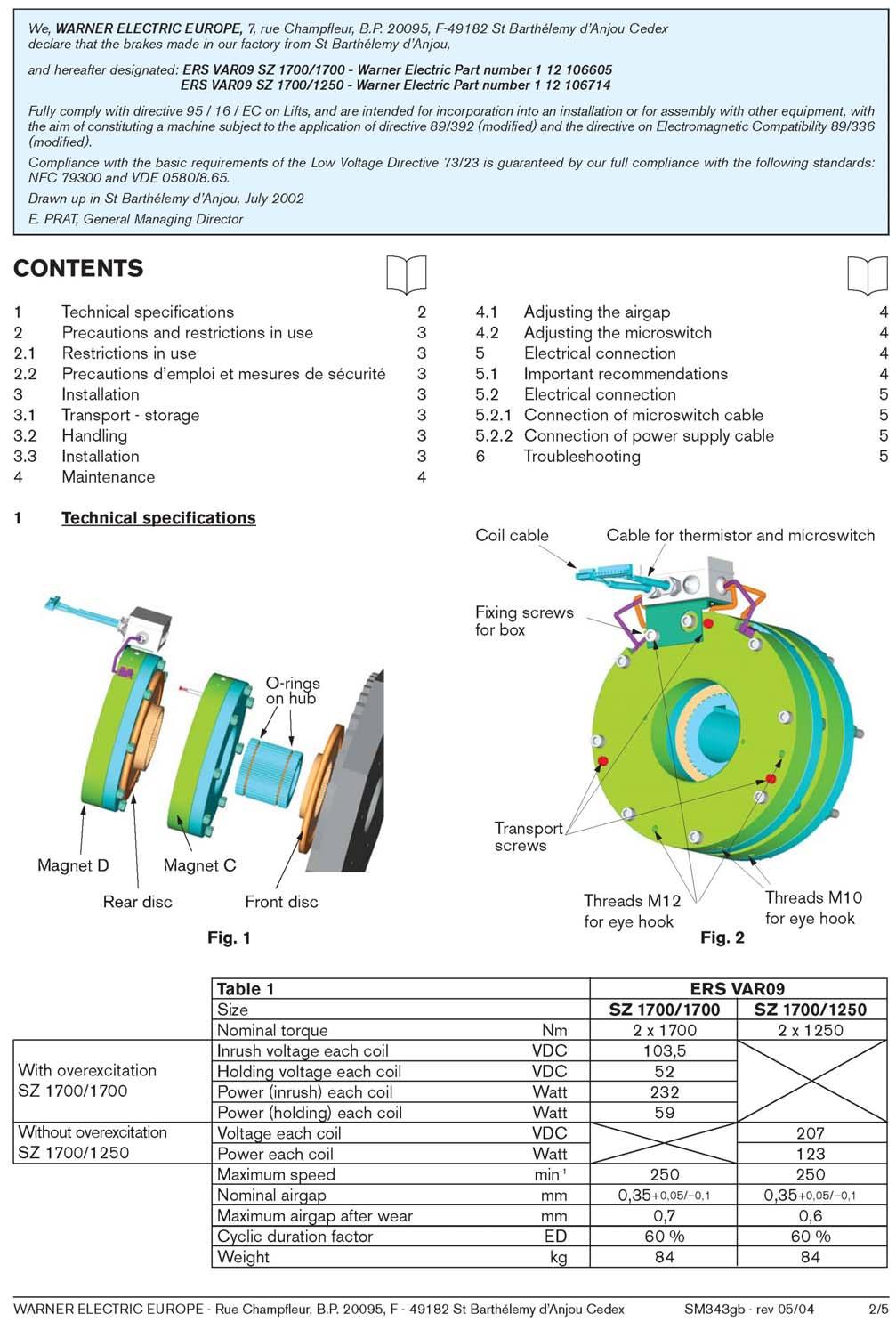
20 3. PRODUCT DESCRIPTION 3.4 Technical data operating brake Type: ERS VAR09 SZ1700 / 1250 ERS VAR09 SZ1700 / 1700 Manufacturer Warner & Tourco Warner & Tourco Brake torque 2 x 1250 Nm 2 x 1700 Nm Version Operating voltage (one brake circuit) Rated output (one brake circuit) Dual-surface disc brake asbestos-free brake linings Without overexcitation 207 VDC voltage Without overexcitation 123 W with voltage applied Maximum ambient temperature 40 C 40 C Max. temperature at full load 100 C 100 C Maximum speed 250 min min -1 Dual-surface disc brake asbestos-free brake linings VDC overexcitation 52 VDC withstand voltage 232 W with overexcitation 59 W with withstand voltage Air gap (stroke per brake circuit) /-0.1 mm /-0.1 mm Maximum air gap in case of wear 0.6 mm 0.7 mm Operating time ED 60 % ED 60 % Length of connecting line 10 m 6 m Weight (incl. accessories) approx. 84 kg approx. 84 kg Type test certificate number ABV 591 ABV 591 Release monitoring (per brake circuit) Switching voltage Switching capacity Operating distance at setting screw 1 x microswitch 24 VDC ma 0.15 mm ThyssenKrupp Aufzugswerke GmbH 20
21 3. PRODUCT DESCRIPTION 3.5 Pulse encoder DAF270 is controlled by means of an enclosed incremental hollow shaft encoder with sine-wave output signals mounted on the rear end of the rotor shaft. Connection to control by means of permanently connected shielded connecting cable of 10 m length with 15-pole sub D connector (RS485) and UNC screwing. The cable shield is connected-up to connector and encoder housing. Connection, installation and drawing see chapters 7.2 and 8.2 Technical data for TTL encoder: Enclosed hollow shaft encoder with 2 signals with 90 phase shift and reference mark. Number of increments (Z): 2048 pulses/revolution Supply voltage: 5 ± 5% V Output driver: RS 485 / sine Output signals: analog / serial 1Vss, max. frequency (-3dB) >/= 200kHz / RS485 EnDat Working temperature range: C Storage temperature range: C Permissible relative humidity: 100 % Max. on-load current with 5 V 150 ma Protection class: IP 64 Connection and installation instructions: Connect connector box and reference potential. Should longer cables be required only use original cables from HEIDENHAIN. Note: the build-on pulse encoder is standard and specially adapted to use with ThyssenKrupp inverter. Use of another type of inverter necessitates a pulse encoder adapted to the respective connected load. Use of a second encoder is not provided with DAF270 machine. Connection assignment at 15-pole Sub-D connector and instructions on installation and wiring see manufacturer's instructions in chapter 8.2. ThyssenKrupp Aufzugswerke GmbH 21
22 3. PRODUCT DESCRIPTION 3.6 Dimensions Dimensions DAF270 M 0xx M20 x 28 deep Brake connection DT= Center of gravity Fig. 3 ThyssenKrupp Aufzugswerke GmbH 22
23 3. PRODUCT DESCRIPTION Dimensions DAF270 L 0xx M20 x 28 deep Brake connection DT = Center of gravity Fig. 4 ThyssenKrupp Aufzugswerke GmbH 23
24 3. PRODUCT DESCRIPTION Dimensions DAF270 M 008 (Tepper variant 1 : 1) 550 M20 x 28 deep 550 Brake connection Dt = Fig. 5 Center of gravity ThyssenKrupp Aufzugswerke GmbH 24

25 3. PRODUCT DESCRIPTION 3.7 Machine frame (optional) The machine frame for DAF270 is designed for machine-room-less elevators to be placed in the headroom. The frame from ThyssenKrupp Aufzugswerke is intended for 2:1 suspension. The drive, terminal rope anchorages and the overspeed governor are also accomodated in the frame. The drive is attached at two profiles and supported by elastic elements. The frame is supported at the support points of the profile ends in the headroom. Machine frame with mounted drive, overspeed governor and terminal rope anchorages for headroom installation ThyssenKrupp Aufzugswerke GmbH 25
 define the frame design and dimensions. DAF270 with frame from LiftEquip for headroom installation. Fig.")
26 3. PRODUCT DESCRIPTION The shaft dimensions and the parallel distance of the ropes at the point of rope departure (ASL) (tailor-made acc. to customer specifications in accordance with available versions) define the frame design and dimensions. DAF270 with frame from LiftEquip for headroom installation. Fig. 7 ThyssenKrupp Aufzugswerke GmbH 26
27 3. PRODUCT DESCRIPTION 3.8 Lubrication DAF270 DAF270 has lifetime-lubricated rolling bearings. The bearings do not require lubrication. ThyssenKrupp Aufzugswerke GmbH 27
28 3. PRODUCT DESCRIPTION 3.9 Name plate DAF270 Version 1. THYSSENKRUPP AUFZUGSWERKE GmbH The current and the technical data are specified on the type plate of product. B3 120 kn 2. LiftEquip The current and the technical data are specified on the type plate of product. ThyssenKrupp Aufzugswerke GmbH 28
29 4. MOUNTING OF MACHINE 4.1 Mounting of machine Assembly DAF270 is designed for headroom installation, but may also be used in the machine room provided that the proper means are made available. 1.) Delivered without machine frame: Delivery of a frame-less drive necessitates the need to make proper assembly and fastening means available. The drive may be attached at the side thread holes dependent on the rope departure direction. Dimensions see chapter 3.6. See to it that the motor connection box is accessible. To comply with the requirements for noise reduction / structure-borne noise transmission isolation elements shall be inserted between drive fastening and support. The tensile force resulting from lateral or diagonal rope departure must be considered and the drive supported properly. 2.) Delivered with machine frame (optional): Optionally DAF270 is delivered assembled and aligned on the machine frame. The frame is assembled in the headroom of the elevator installation in accordance with the customer's specifications. The number of rubber elements and their arrangement depends on the overall weight load and the possible supports. The necessary or permissible individual load depends on the characteristic values of the isolation element. The rubber elements are to be arranged in such a way that the load is distributed equally. Design and dimension of the machine frame in accordance with the customer's specifications. Note: prior to start setting the machine into operation remove the plastic cover of the ventilation hole underside the housing. (Fig. 1 pos. 4) How to align the machine frame The machine shall be assembled or installed in accordance with the layout drawing. Align the rope departure of traction sheave and deflection pulley in accordance with the drawing so that it is in vertical line with the car rope pulley or the counterweight pulley. When the ropes are tensioned, the machine shall be arranged horizontally aligned at the base plate. Use metal plates to ensure that the base is perfectly horizontal. ThyssenKrupp Aufzugswerke GmbH 29
30 4. MOUNTING OF MACHINE How to align the machine on the frame: The machine is delivered aligned. After disassembly of drive or displacing of machine (due to exchanged traction sheave, for example) verify that the machine is properly aligned and re-align, if required. Note: when the machine is completely installed, tighten the fastening screws with the pre-set torque. See chapter 8.1. ThyssenKrupp Aufzugswerke GmbH 30

 and PTC tripping device (or frequency inverter connection provided for that purpose.")
31 4. MOUNTING OF MACHINE 4.2 Motor connection Observe terminal diagram at the cover of the motor connection box or terminal diagram. Adhere to fig. 8. Verify that the safety instructions and the respective local building regulations are complied with. Motor connection data of respective motor type see 3.3 Motor terminal diagram: for frequency-controlled motors Th Th U V W Grd. Fig. 8 Temperature monitoring motor Fig. 9 Connect terminal connection "Th" (thermistor) and PTC tripping device (or frequency inverter connection provided for that purpose. Voltage applied shall not exceed 2.5 V. ThyssenKrupp Aufzugswerke GmbH 31

32 4. MOUNTING OF MACHINE 4.3 Brake connection Description and important instructions see chapter 3.4 and manufacturer's instructions in chapter Brake and encoder connection Fig Brake housing 7 Conn. PTC resistors motor 2 Brake test switch D 8 Encoder connection 3 Brake voltage connection 9 Fastening bow 4 Brake test switch 10 Bearing bracket 5 Terminal box 11 Cover plate brake 6 Brake test switch C 12 Encoder ThyssenKrupp Aufzugswerke GmbH 32
 = brake coil D and cores 3;4 (terminals 3; 4) = brake coil C - and brake circuit.")
33 4. MOUNTING OF MACHINE Connection of brake: Voltage supply of release coils and control switches The brake release coils are located in the connection box (fig. 10 pos. 5) at the front brake side. Connect four-conductor cable - cores 1; 2 (terminals 1; 2) = brake coil D and cores 3;4 (terminals 3; 4) = brake coil C - and brake circuit. Terminal Connection 11 Brake monitoring D 10 9 Brake monitoring C Thermal monitoring brake 5 Series connection Th Brake connection brake D Brake connection brake C Fig. 11 Connection of screened six-core cable from connection box (cores 1;2 (terminal 6; 7) = temperature monitoring brake) and motor temperature monitoring with evaluator to be made by the customer. The voltage applied shall not exceed 2.5 V. Cores 3; 4 (terminals 8; 9) = brake monitoring D; and 5; 6 (terminals 10; 11) = brake monitoring C, must be connected to the brake monitoring. Note: it is recommended to adhere to the instructions and recommendations of the brake manufacturer as the performance of the brake in service mainly depends on the circuit selected. See chapter 8.3. ThyssenKrupp Aufzugswerke GmbH 33
34 4. MOUNTING OF MACHINE For operating voltage of magnet coils (direct current acc. to DIN IECE038) see name plate at the brake body. Connection and corresponding type of brake see table Technical data chapter 3.4. When the brake ERS VAR09 SZ1700 / 1700 is connected, make sure that the necessary overexitation is always maintained. Disregard may affect safe and quick operation! No overexcitation possible with brake type ERS VAR09 SZ1700 / Note: when disconnecting the brake coils alternative power supply is recommended. Direct power supply necessitates protection of the coils against the risk of transient overvoltage acc. to VDE Details on connection of connector plugs at the brake line ends see fig. 14 and chapter 8.3, Manufacturer's instructions (Warner) point Miniature fuse: the fuses in the power supply lines are to be adapted to the customer's power supply. Connection temperature monitoring brake: The PTC thermistor detectors are series-connected (core grey/grey) at the factory at the brake terminal box (terminal 5-7) via a screened cable. See terminal assignment and connections at terminal box (fig. 11) and connection assignment for conductor in fig. 14. Terminals "Th" are to be connected to a PTC thermistor tripping device by the customer. The voltage applied shall not exceed 2.5V. See to it that the distance to all revolving parts is observed by persons laying connecting cables. Corresponding counter measures are to be made. Do not use the same cable duct for connecting lines used for temperature monitoring and brake test and motor connection line. Connection release monitoring brakes: Microswitches are attached at the coil body of the magnet brake. A pre-set and pre-assembled switch per brake circuit each monitors the brake condition (opened/closed). The setting shall not be changed. When replacing make sure that the switch setting is in accordance with the instructions in chapter 7.3. Check the switches for proper setting and correct function. Fig. 12 Connection release monitoring switch Input connection brown Break contact connection black Make contact connection blue ThyssenKrupp Aufzugswerke GmbH 34
35 4. MOUNTING OF MACHINE The switch connections are connected at the terminal box (fig. 11) via a 6-core screened cable (fig. 14) for signal processing. The connection at the customer is made as break contact. An evaluation of the signal of both switch conditions must be made by the customer! Switching current range min. 10 ma to max. 100 ma at 24 VDC. Further details see chapter 8.3 Manufacturer's instructions. After connecting check brake and monitoring switches for correct functioning. Note: an appropriate access to the brake and microswitches for the inspection, adjustment or replacement works must be possible. ThyssenKrupp Aufzugswerke GmbH 35
 9")
36 4. MOUNTING OF MACHINE Magnetic brake with release monitoring Air gap Fig Contact extension for release monitoring C 2 Bearing bracket 3 Brake lining 4 Brake coil body C 5 Brake disc D 6 Anchor disc D 7 Brake coil body D 8 Cheese head screw (switch fastening) 9 Setting screw brake release C 10 Brake release switch C (release monitoring) 11 Eyebolt 12 Terminal box ThyssenKrupp Aufzugswerke GmbH 36
37 4. MOUNTING OF MACHINE Connecting cables magnetic brake PHOENIX conductor Coil D ± ± 3 50 ± 3 6. Brake coil connection Adernendhülsen Adernendhülsen At the customer Connection side terminal box at brake Coil C or ± 15 P PHOENIX conductor Core 1 4 Core Core 3 8 Core 4 9 Core 5 10 Core 6 Thermistor Magnet C and D Switch C Switch D 120 ± 3 70 ± ± Fig Screening Brake monitoring and thermistor connection ThyssenKrupp Aufzugswerke GmbH 37
38 4. MOUNTING OF MACHINE 4.4 Encoder connection The encoder at the rear shaft end is screw-connected to the brake housing by means of a fastening bracket. See fig. 10. Connection to control by means of a 10 m long connecting cable with 15-pole sub-d connector. Pin assignment of connector see chapter 8.2 Manufacturer's instructions. Description and technical data for encoder connection see chapter 3.5. ThyssenKrupp Aufzugswerke GmbH 38
39
40 4. MOUNTING OF MACHINE 4.5 Schematic diagram DAF270 +M Winding Motor Temperature monitoring Encoder Brake magnet Brake Temperature monitoring Control switch ThyssenKrupp Aufzugswerke GmbH 40
41 5/6. PUTTING INTO SERVICE AND SERVICING 5.1 Putting DAF 270 into service Before you start putting the machine into service the following points are to be checked and/or the following works performed: Check mounting and aligning of machine, frame and rope departure Check fastening of machine and frame Tighten screws and secure with pre-set torque (see table tightening torques in 8.1) Check supply terminals, earthing of motor and brakes for connection and test Check thermal monitoring of motor and brake for connection to connection PTC thermistor tripping device (not part of the supply schedule) Check brake and encoder for correct connection to control Check lower release hole of drive for removal of plastic cover Check whether safety, accessory and installations tools are removed from the danger zone Check armature base plate and brake connection (chapter 6.2 c) Check brake control switches for proper connection and functioning (chapter 7.3) Perform brake test with one acting brake shoe each (chapter 6.2) Check brake release (for emergency rescue even in case of power failure) for proper functioning (not part of supply schedule) Check rope guard cover or rope support for proper mounting and distance (max. 2mm) (not part of the supply schedule of machine frame) Check special mountings (optional) for correct mounting and functioning Attention: if the drive is operated by a brake control circuit instead of an emergency braking system (safety gear) against overspeed in upwards direction, it must be observed that the elevator installation shall only be put into service with the brake monitoring faultlessly functioning! Never put the installation into service without brake test switches by disconnecting the check-back or brake test switches and resetting the nonvolatile memory (EPROM). Disregard may cause danger to life of persons. ThyssenKrupp Aufzugswerke GmbH 41
42 5/6. PUTTING INTO SERVICE AND SERVICING 6.1 Servicing of DAF270 Servicing interval: servicing of the machine should be carried out at least once a year, preferably in the course of the general elevator servicing. Note: installation and servicing works shall only be carried out by trained and qualified personnel. These persons must know and observe the respective regulations and requirements for elevator installations as well as the accident prevention regulations. Further information concerning proceeding, adjustment and data see chapters: Check armature base plate - air gap between armature disc 6.2 and brake coil body for wear of brakes Check brake deceleration 6.2 Check brake control switches for proper functioning 7.3 Check screw-connections and fastenings for proper 8.1 tightening (tightening torque) Check grooves of traction sheave and drive fastening for 7.4 proper tightening; re-tighten, if required. Check groove profiles for damage and wear Check electrical connections for correct working, sound condition and proper fastening Check motor bearings for wear (noise, backlash) Check protective and safety equipment; test for correct working Check protective and safety equipment; check danger and instruction signs; check signs for proper affixing and visibility ThyssenKrupp Aufzugswerke GmbH 42
43 5/6. PUTTING INTO SERVICE AND SERVICING 6.2 Drive brake test Inspection interval: inspection of the brake shall be carried before initial operation, after exchange of brake and once a year in the course of the general elevator servicing. a) The brake deceleration is tested for each brake circuit individually. Note: before testing: Inspection signs must be made available at the landing doors. Close the doors acc. to the rules. Make sure that the car is empty. While testing the brake circuit with the empty car moving upwards the car must be at least 2 landings below the upper-most landing. While testing the brake circuit with the fully loaded car moving downward the car must be at least 2 landings above the lower-most landing. The single circuits are tested by applying below voltage at the single brake coils: Brake type SZ1700/1700 with excitation / withstand voltage 104 / 52 VDC Brake type SZ1700/1200 with operating voltage 207 VDC While testing the brake circuit, the brake of the 2. brake circuit must be released during the braking operation (even in case of emergency stop). Withstand voltage must be applied at the magnet coil of the 2. brake circuit. Disable release monitoring of the brakes until the respective brake circuit is tested. Attention: should the elevator move after release of one brake circuit or fail to decelerate sensibly during the braking operation, switch the continuously energised coil off immediately. The dual circuit braking function is not guaranteed. Check brake! Testing with deceleration measure: Check brake deceleration at each brake circuit individually. Testing may be performed while moving the empty car upwards or the fully loaded car downwards. Connect deceleration measure Activate normal run (brake to be tested is released) Activate emergency stop as soon as rated speed is reached (brake to be tested closes). While testing the brake circuits individually, the motor coils should be de-energized. Motor braking may lead to wrong test results. Determine deceleration for 1. brake circuit using a measuring device Compare measurement and reference value Remove continuous voltage supply at continuously open 2. brake circuit and connect to 1. brake circuit. ThyssenKrupp Aufzugswerke GmbH 43
44 5/6. PUTTING INTO SERVICE AND SERVICING Repeat test at 2. brake circuit. Deceleration values: Minimum deceleration for one brake circuit Minimum deceleration for both brake circuits 0.4 m/s² 1.0 m/s² Attention: after testing the brake, remove the continuous control voltage at the 2. brake ciruit and establish the original condition (both brakes acting at the same time). Enable the release control switches at the brakes again. Simple testing of braking deceleration without measuring device: (this inspection method only applies to travel heights 7m and control point observable from brake operation point.) Inspection sequence: The details described in a are to be observed. Provide terminal for continuous power supply at brake circuit of the 2. brake coil. Move the fully loaded car at least two landings above the bottom-most landing. Mark ropes at the height of the control point. The control point shall be easily visible from the brake operation position. (Marking at bracket height, for example). Move the car upwards to the nearest landing. While testing, apply continuous control voltage at 2. brake. Note: voltage must be present even with the main switch disabled. If not, both brakes will become effective. Move fully loaded car downwards at normal speed. Observe control point and ropes from brake operation position. Switch off main switch as soon as marking reaches the control point. Measure distance between marking and control point. This distance corresponds approximately to the stopping distance of the tested brake circuit. Remove continous operating voltage and apply at tested brake coil. Compare stopping distance result and reference value. Stopping distance The max. stopping distance for single brake circuit shall not exceed: 1.8 m for installations with V N 1.0 m/s; 3.5 m for installations with V N 1,6 m/s; 5.0 m for installations with V N 2.0 m/s. (These values only apply to simple testing) Repeat described testing for 2. brake circuit. Attention: when the brake is tested, the original switching condition is to be established (operation of both brake coils at the same time and connection of brake test switch). ThyssenKrupp Aufzugswerke GmbH 44
45 5/6. PUTTING INTO SERVICE AND SERVICING b) Testing of both brake circuits When a brake circuit is tested individually, activate emergency stop operation and repeat testing for both brake circuits. Deceleration must fall below the stopping distance of the single circuit tests! c) Inspection of wearing condition: Put a feeler gauge between coil body and armature disk and check air gap. The brake must be closed (coils de-energized). Repeat several times at the circumference. This method only applies to the front brake which is easily accessible. The second brake is mounted recessed in the bearing bracket. Testing the air gap at the second, recessed mounted brake: Screw the enclosed hexagon screws M8 x 150 (marked red) into 8.4 mm holes at the brake front (see fig.15 pos. 11). Screw in until the distance between the screwhead and the support is approx. 1-3 mm. Attach dial gauge and holder at the brake and vertically align the dial gauge towards the screwhead. (See fig. 15) Energize brake circuit to be tested shortly several times and read screw stroke at dial gauge. (The stroke corresponds to the airgap at the front brake). Afterwards remove screws and reposit. Replace brake as soon as the max. limit air gap is reached. Repairs to be performed at the factory! Discription of brake replacement see chapter 7.5. Note: the electro magnet may fail to attract the armature base plate properly and without delay if the air gap is too large. This means that the brake opens delayed or fails to open. Never tighten the red screws (fig.15, pos. 11). Remove the screws before operation is started. In case of disregard the brakes cannot be closed! Table air gap brake Typ Rated torque for 2 brake circuits Rated air gap Braked complete Limit air gap Braked complete Nm 0.35 mm ± 0,1 max. 0.6 mm Nm 0.35 mm ± 0,1 max. 0.7 mm Rated air gap Limit air gap brake closed (at zero current), new lining brake closed (at zero current), worn off lining ThyssenKrupp Aufzugswerke GmbH 45
 8 Detent edged washer SK12 2 Brake connection (4-pole) 9 Hexagon socket M12x200 3 Connection box brake 10 Protecting plate 4 Dial gauge 11 Hexagon")
46 5/6. PUTTING INTO SERVICE AND SERVICING Representation: checking of stroke movement of anchor plates (release gap) at non-accessible brake C Fig Brake switch connection (6-pole) 8 Detent edged washer SK12 2 Brake connection (4-pole) 9 Hexagon socket M12x200 3 Connection box brake 10 Protecting plate 4 Dial gauge 11 Hexagon socket M8x150 5 Dial gauge holder 12 Brake magnet housing D 6 Transport eyebolt M12 13 Encoder 7 Encoder connection 14 Hexagon socket M12 x 20 ThyssenKrupp Aufzugswerke GmbH 46
47 7/8. MAINTENANCE / ANNEX 7.1 Replacing of traction sheave Fig. 16 View rotated 90 1 Traction sheave 2 Fitting key 25 x 14 x 90 mm 3 Disc 4 Detent edged washer SK16 5 Hexagon socket M 16 x microencapsulated Tightening torque = 195 Nm 6 Motor shaft 7 Motor housing 8 Motor connection box 9 Forcing hole Installation sequence traction sheave replacement Disassembly: Switch off power supply; secure car and counterweight Remove rope fixing beam Remove load from traction sheave; discard ropes; secure traction sheave with lifting device ThyssenKrupp Aufzugswerke GmbH 47
48 7/8. MAINTENANCE / ANNEX Loosen screws on mounting disc of traction sheave; put screws in outer hole circle of disk (fig. 16, pos. 3) and loosely screw in traction sheave hub (holes pos. 8). Place a washer approx. 5 10mm thick between shaft end and disc. Tighten screws uniformly and remove traction sheave from motor shaft. Put traction sheave down using lifting device. Remove mounting disc from traction sheave Assembly: Clean shaft end and traction sheave holes; never make any dimensional changes in featherkey, groove, shaft or drilled holes Never grease or oil shaft and holes Carefully fit new traction sheave to conical end of motor shaft Bring position of featherkey and groove in line. Push traction sheave on motor shaft Assemble traction sheave using already available screws and tighten in accordance with tightening torque. Disassemble screws and disc Check fit cover of traction sheave holes (the pressed on bearing surface of the traction sheave must project the front shaft at least 1.5 mm) Fit and screw disc to motor shaft using new micro-encapsulated screws and detent edged washers Tighten fastening screws using torque wrench and bring to required torque of 195 Nm in several operations. Replace rope; remove securing devices at car and ropes Screw on rope fixing beam Attention: the traction sheave may work loose if assembled improperly. When the traction sheave is to be replaced, enclosed new microencapsulated screws must be used. Observe screw strength and tightening torque! Note: only use micro-encapsulated screws twice, since otherwise the adhesive force is no longer effective ThyssenKrupp Aufzugswerke GmbH 48
49 7/8. MAINTENANCE / ANNEX 7.2 Replacing of pulse encoder Fig Push onto or remove from shaft end 1 Shaft end 2 Mounting elbow 3 Clamp bolt 4 Fastening screw 5 Female component - encoder 6 Encoder housing Technical data, see chapter 2.8 Manufacturer's instructions chapter 8.3 Disassembly: Switch off power supply Remove connector plug of encoder connection on control. Unscrew clamp bolt at female encoder component using hexagon socket wrench M2.5 (2 screws pos. 3) Unscrew encoder and fixing strap at brake (2 x M8) Carefully remove encoder from shaft end into axial direction ThyssenKrupp Aufzugswerke GmbH 49

50 7/8. MAINTENANCE / ANNEX Assembly: Clean but do not grease shaft end before you start mounting the encoder. The shaft end must be clean and free of grease Carefully turn and push fixing strap and female encoder component onto shaft end in direction of arrow until the fixing strap is close to the brake Carefully tighten clamping bolt (pos.3) in the female component without distorting the encoder. The encoder housing must be easy to move on the shaft Turn encoder housing until the connecting cable is positioned properly. Align strap holes towards threaded holes of brake; screw-connect fixing strap at brake Connect encoder connection to control Adjust encoder Attention: when performing test and inspection works never switch the drive on with the encoder unconnected; this can cause damage of electronic components in the encoder. 1 2 Fig Hexagon socket screw 2 Fixing strap 3 Brake housing 4 Encoder 5 Shaft end 6 Connecting line 7 Clamping bolt Note: re-adjust the encoder with the pulse encoder being replaced or the rotor position changed. Proceeding see operating manual of frequency inverter. ThyssenKrupp Aufzugswerke GmbH 50
51 7/8. MAINTENANCE / ANNEX 7.3 Replacing of brake monitoring switch Secure car and counterweight Switch off power supply and protect installation against unintentional switching on Disconnect defective switch at connection box (fig. 11) and replace Mount new switch at brake coil body, fig. 13, pos. 10, and connect to terminal box Setting and checking of brake monitoring switch: Screw in setting screw M4 for switch operation by two to three screw turns. The switching contact of the brake monitoring switch shall not touch the setting screw Apply operating voltage at brake circuit to be set Set distance between switching contact and setting screw to 0.15 mm using a feeler gauge Unscrew setting screw until the contact of the microswitch reaches the switching point Remove feeler gauge; disconnect operating voltage Check microswitch for correct functioning by switching the brakes on and off repeatedly Seal fastening screws of release monitoring using sealing wax Put installation into operation ThyssenKrupp Aufzugswerke GmbH 51
52 7/8. MAINTENANCE / ANNEX 7.4 Silencing of the brakes The used noise dampening has been adjusted at the factory. However the noise dampening is subject to a certain aging dependent on the application or operational conditions (switching frequency, torque adjustment, natural drive vibration). The brake must be completely exchanged, if the noise behaviour of the brake rises to an inadmissible level. An exchange of the damping elements is only possible at the manufacturer. ThyssenKrupp Aufzugswerke GmbH 52
53 7/8. MAINTENANCE / ANNEX 7.5 Replacing of brakes Air gap Air gap Fig Motor shaft 7 Brake magnet housing 2 Hexagon screw M8 x 40 8 Hexagon screw M12 x Motor housing 9 Encoder 4 Bearing bracket 10 Fixing strap 5 Braking rotor 11 Toothed sleeve 6 Armature base plate 12 O ring ThyssenKrupp Aufzugswerke GmbH 53
54 7/8. MAINTENANCE / ANNEX Replacing of dual-circuit disc brake (Warner) Note: for safety reasons, the brake must be completely replaced as soon as the brake is defective or the wear limit reached. Exchange of the brake to be made in the house Warner. To replace the brake proceed as follows: Disasssembly: Switch off power supply and secure installation against unintentional switching on Rest counterweight on buffer; secure car Remove cover plate at brake Disconnect or unplug connecting cables between brake monitoring switch, PTC thermistor and brake connections at brake. Remove terminal connection between encoder and motor shaft. Remove fixing strap at brake housing and encoder at the same time. Assembly instructions see chapter 7.2. Attention! Prior to continue disassembly screw in enclosed red hexagon sockets (M8x150). In case of disregard the brake parts will be separated by spring force. Screw transport eyebolts (M12) into side threads at the brake housing circumference. Fix brakes at lifting device Mark position of connection box at drive Remove fastening screws (fig. 19 pos. 8) Carefully push off brake housing and rotor from toothed sleeve (fig. 19 pos. 11) and place aside Carefully push off rear rotor at bearing bracket (use two screw drives as lever, if necessary) Note: the toothed sleeve is pushed over the shaft end of the warmed up drive (240 C). Non-defective pushing off is not possible, therefore. Re-use if toothing is free from any visible damage. Assembly: Fasten new brake at lifting device Clean and slightly grease toothed sleeve at motor shaft end Replace defective O rings at toothed sleeve, if necessary Clean braking surface at bearing bracket of drive using special cleaner and slightly grease (with DELOTHEN NK1, for example) Mount front brake rotor to toothed sleeve (make sure that the rotor is mounted the right way round; hub collar backwards!) Align new brake towards toothed sleeve using lifting device. Observe position of connection box (marking at bearing bracket). Before you start mounting the brake, connect the brake coils and make sure that the brake is open. In case of disregard, the brake rotor blocks and the brake housing cannot be moved and aligned while fitting the screws. Mount brake and second brake rotor; tighten fastening screws and observe proper tightening torque. ThyssenKrupp Aufzugswerke GmbH 54
55 7/8. MAINTENANCE / ANNEX Attention: avoid any impact onto the motor shaft as this may cause deterioration of the rolling bearings. Push rotor manually with a slight pressure over the toothed sleeve (O ring). Loosen red transport eyebolts at front side of brake (do not unscrew). Check air gap of rear brake at bearing bracket using a dial gauge. (See description in chapter 6.2) Then unscrew transport eyebolts and reposit. The screws must be available for future air gap checking and installation works. Check air gap at front brake using feler gauge Mount protective cover at brake housing. Observe tightening torque. (Observe sequence of installation. Disregard may cause deterioration of the cover!) Mount pulse encoder (see chapter 7.2) Connect brake magnet coils, brake monitoring switches, thermal elements and encoder to control Remove transport contrivances at car and counterweight When the drive or the brakes are replaced, check the drive brake for correct functioning before you start operation. See description in chapter 6.2. ThyssenKrupp Aufzugswerke GmbH 55
56 7/8. MAINTENANCE / ANNEX 8.1 Tightening torque - mechanical strength Attention: observe required screw strength and tightening torque when performing any work on the machine or exchanging parts. Non-microencapsulated screws must be secured against unintentional working loose using detent edged washers. The values specified apply to the applications indicated below: Hexagon socket screws ISO 4762 (DIN 912) Hexagon bolts ISO 4014 / 4017 (DIN 931 / 933) To observe the required torque, tighten the screws using a torque spanner! Dimension Tightening torque M A [Nm] Strength M4 2,6 M5 5,3 M6 9, M M M M M M Attaching encoder on shaft Clamping bolt 2,5 Nm Attaching encoder on brake M4 x 4 1,0 Nm ThyssenKrupp Aufzugswerke GmbH 56
57
58 Mounting dimensions 4 x M4 30 h7 Installation
59
60 87 45 SW3 (2X)) Md = 2,5 ± 0,5Nm mm
61 Pin assignment 15-pole sub-d connector (pin) nicht belegt
62
63
A company of ThyssenKrupp Elevator. ThyssenKrupp Aufzugswerke. Operating Manual. Oil buffer
 A company of ThyssenKrupp Elevator ThyssenKrupp Aufzugswerke Operating Manual Oil buffer OPERATING MANUAL Printer s imprint All rights reserved. Copyright by: THYSSENKRUPP AUFZUGSWERKE GMBH P.O. box 23
Instruction manual and installation guide Traction sheave brake TSB TSB
 Instruction manual and installation guide Traction sheave brake TSB 2000-1 TSB 2000-2 Content Traction sheave brake Page 1. Safety 2 1.1 Explanation of symbols 2 1.2. General safety instructions 3 2. Product
Electrically Released Brakes ERS VAR11-01 FT = 4100 N
 SM429gb - rev 06/11 S E R V I C E Electrically Released Brakes ERS VAR11-01 FT = 4100 N M A N U A L EC type certificate ABV 775/1 According to drawing 1 12 106946 TUV SUD Industrie Service WARNER ELECTRIC
Operating Manual Machine TW63
 Operating Manual Machine TW63 A company of ThyssenKrupp Elevator ThyssenKrupp Aufzugswerke ThyssenKrupp Printer s imprint All rights reserved Copyright by: THYSSENKRUPP AUFZUGSWERKE GmbH P.O. box 23 03
D58 Series Brake Instructions
 D58 Series Brake Instructions 4740 W. Electric Avenue Milwaukee, WI 53219 414/672-7830 FAX 414/672-5354 www. dingsbrakes.com Safety information 2 Safety information 2.1 Persons responsible for the safety
Electrically Released Brakes ERS VAR10 SZ 5000/5000
 SM366gb - rev 01/06 S E R V I C E Electrically Released Brakes ERS VAR10 SZ 5000/5000 M A N U A L EC type certificate ABV 604/1 according drawing 1 12 106602 WARNER ELECTRIC EUROPE Rue Champfleur, B.P.
Installation and Operating Instructions for ROBA-stop -silenzio Type 896. _. Sizes
 Please read and observe this Operating Instruction carefully! A possible malfunction or failure of the clutch and damage may be caused by not observing it Table of contents: Page1: - Table of contents
Product Information Overspeed governor GB 260
 Product Information GB 260 Copyright as per DIN ISO 16016. Manufactured under licence of C. Haushahn GmbH & Co. I Subject to modification. Published by SLC Sautter Lift Components GmbH & Co. KG Borsigstrasse
SERVO MOTORS BRUSHLESS SERVO MOTORS OPERATING INSTRUCTIONS 2016
 SERVO MOTORS BRUSHLESS SERVO MOTORS OPERATING INSTRUCTIONS 2016 3009/16 en Ed.02.2016 Read these Operating Instructions before performing any transportation, installation, commissioning, maintenance or
Installation and Operating Instructions for ROBA-stop -Positioning Brake Type 80_.41_._ Sizes 3 11
 Please read and observe this Operating Instruction carefully! A possible malfunction or failure of the brake and any damage may be caused by not observing it. Table of contents: Page 1: Page 2: Page 3:
ThyssenKrupp Aufzugswerke. A company of ThyssenKrupp Elevator. Operating Manual. Machine TW160
 A company of ThyssenKrupp Elevator ThyssenKrupp Aufzugswerke Operating Manual Machine TW160 OPERATING INSTRUCTIONS Imprint All rights reserved Copyright by: THYSSENKRUPP AUFZUGSWERKE GmbH Postfach 23
INSTRUCTION MANUAL. I/P Converter DSG BXXY3Z DSG BXXY4Z
 INSTRUCTION MANUAL I/P Converter DSG BXXY3Z DSG BXXY4Z Revision 2.0 3.626 016136 en Page 1/15 Should you have any questions concerning the I/P converter, please contact the Service Department of the Product
ROBATIC ROBA -quick ROBA -takt. Reliable coupling and braking.
 Reliable coupling and braking Equipment Technology Packaging Machinery Conveyors and Materials Handling Equipment Door drives Indexing tables ROBATIC ROBA -quick ROBA -takt www.mayr.de Electromagnetic
Installation and Operational Instructions for ROBA-stop Holding Brake Type _._
 Please read these Installation Instructions carefully and follow them accordingly! Ignoring these Instructions may lead to malfunctions or to brake failure, resulting in damage to other parts. Contents:
Installation and Operating Instructions for ROBA-stop -silenzio Type 896._3_. Sizes
 Please read and observe this Operating Instruction carefully! A possible malfunction or failure of the clutch and damage may be caused by not observing it. Table of contents: Page 1: - Table of contents
SERVO MOTORS BRUSHLESS SERVO MOTORS ATEX ZONE 2-22 OPERATING INSTRUCTIONS 2016
 SERVO MOTORS BRUSHLESS SERVO MOTORS ATEX ZONE 2-22 OPERATING INSTRUCTIONS 2016 3010/16 en Ed.10.2016 Read these Operating Instructions before performing any transportation, installation, commissioning,
Installation and Operating Instructions Electric Vibrators HV/VFL Series
 Installation and Operating Instructions Electric Vibrators HV/VFL Series Original Instruction Würges Vibrationstechnik GmbH Daimlerstraße 9 D-86356 Neusäß Telephone +49 821 463081 Telefax +49 821 463084
PURE SINE WAVE DC TO AC POWER INVERTER
 PURE SINE WAVE DC TO AC POWER INVERTER 60S-12A / 60S-24A 60S-12E / 60S-24E 100S-12A / 100S-24A 100S-12E / 100S-24E 150S-12A / 150S-24A 150S-12E / 150S-24E Instruction manual SINE WAVE INVERTER Please read
These operating instructions apply for: NCX 380 NCZ 300 NCX 480 NCZ 370 NCX 580 L NCZ 480 NCX 660 K NCZ 560 NCZ 660 NCZ 800
 Original instructions Operating Instructions for May 2010 Electric Internal Vibrators BA No. 1092E Series NCX and NCZ These operating instructions apply for: NCX 380 NCZ 300 NCX 480 NCZ 370 NCX 580 L NCZ
Electromagnetic clutch-brake combinations INTORQ
 Electromagnetic clutch-brake combinations INTORQ 14.800 14.867 7.5 120 Nm setting the standard 2 CBC en 5/2005 Contents Clutch-brake combinations Product information 4 Type code 6 Design selection 8 Overview
Assembly and Maintenance Manual Type RSBW
 Assembly and Maintenance Manual Type RSBW Hatschekstr. 36 69126 Heidelberg Germany Tel +49(0)6221 30470 Tel +49(0)6221 304731 info@stieber.de www.stieber.de Stieber Clutch Date of issue: 16/03/2017 GB
Stromag Dessau. safety in motion PRODUCT CATALOGUE. NFF4F-LS Brake. for Slow-Running High Torque Drivelines, in harsh environment
 Stromag Dessau safety in motion PRODUCT CATALOGUE NFF4F-LS Brake for Slow-Running High Torque Drivelines, in harsh environment ENGINEERING THAT MOVES THE WORLD Applications Holding brake variations with
Solenoid Operator 0516 / 1216
 nass magnet GmbH Edition no. 2 Eckenerstraße 4-6 2007-01-10 D-30179 Hannover Rev.2 070110 Solenoid Operator 0516 / 1216 Operating Instructions NN 8220 126 and EC Declaration of Conformity Dear Customer!
Operating Manual (Edition 04/2004) sinamics. Braking Module / Braking Resistor SINAMICS G130
 sinamics. Braking Module / Braking Resistor SINAMICS G130") Operating Manual (Edition 04/2004) sinamics Braking Module / Braking Resistor SINAMICS G130 04/04 Contents Contents 1 Safety Information 1-1 2 General 2-1 3 Mechanical Installation 3-1 4 Connection 4-1
Operating Manual (Edition 04/2004) sinamics Braking Module / Braking Resistor SINAMICS G130 04/04 Contents Contents 1 Safety Information 1-1 2 General 2-1 3 Mechanical Installation 3-1 4 Connection 4-1
Lenze. Drives with worm gearboxes 52.
 6 887 Lenze Drives with worm gearboxes 5. Lenze Drive Systems GmbH, Postfach 0 5, D-76 Hameln, Site: Groß Berkel, Hans-Lenze-Straße, D-855 Aerzen, Phone ++9 (0) 55 8-0, Telefax ++9 (0) 55 8- E-Mail: Lenze@Lenze.de
User Guide. Lubricus Lubrication System LUB-D1/LUB-D2/LUB-D3/LUB-D4 (24 VDC)
") User Guide Lubricus Lubrication System LUB-D1/LUB-D2/LUB-D3/LUB-D4 (24 VDC) version 04/2013 Content General Information 3 Warning 3 Scope of Supply 3 Overview 3 General safety details 4 Intended use 4
User Guide Lubricus Lubrication System LUB-D1/LUB-D2/LUB-D3/LUB-D4 (24 VDC) version 04/2013 Content General Information 3 Warning 3 Scope of Supply 3 Overview 3 General safety details 4 Intended use 4
Solenoid Operator 0513 / 1213
 nass magnet GmbH Run Nr. 5 Eckenerstraße 4-6 24.10.2006 D-30179 Hannover Rev. 5 061024 Solenoid Operator 0513 / 1213 Operating Instructions NN 8220 112 and EC Declaration of Conformity Dear Customer! In
BAH series Use and Maintenance Manual
 Page 1 of 15 BAH 225-280 series Use and Maintenance Manual Page 2 of 15 We would like to thank you for trusting us and buying our product. Field of application Before starting the motor, it s necessary
Translation of the Original operating instructions Lifting device Z 70 /...
 Translation of the Original operating instructions Lifting device Z 70 /... Content 1. Lifting device / Correct use according to regulations 2. Basic principles 3. General information 4. Special remarks
Operating Instructions for Elevator Buffers type LP
 Operating Instructions for Elevator Buffers type LP 1 Scope of application The Elevator Buffer type LP is an energy dissipation type buffer according to EN 81-1/2, EN 81-20, EN 81-50 5.5 and therefore
Installation and Operational Instructions for ROBATIC -clutch Types _.0 and _.0 Sizes 3 7
 Please read these Installation and Operational Instructions carefully and follow them accordingly! Ignoring these Instructions may lead to malfunction or to clutch failure, resulting in damage to other
VEM motors Thurm GmbH
 VEM motors Thurm GmbH Installation, Operating and Maintenance Instructions Single-Phase Squirrel-Cage Induction Motors, Standard Version March 2005 1. General To avoid damage to the motors and equipment
Service Instructions. Syntron Electromagnetic Feeder Model: F-010-B DF-010-B
 Service Instructions Syntron Electromagnetic Feeder Model: F-010-B DF-010-B Service Manual Syntron Electromagnetic Feeder Models: F-010-B and DF-010-B Installation Operation Maintenance 1 Table of Contents
Electropneumatic Converters i/p Converters Type 6111 Mounting and Operating Instructions EB 6111 EN
 Electropneumatic Converters i/p Converters Type 6111 Fig. 1 Type 6111 in standard version Fig. Type 6111 mounted on a supply air manifold Fig. 3 Type 6111 in field enclosure Mounting and Operating Instructions
Product Information ECN 425 EQN 437. Absolute Rotary Encoders with Hollow Shaft and Expanding Ring Coupling for Safety-Related Applications
 Product Information ECN 425 EQN 437 Absolute Rotary Encoders with Hollow Shaft and Expanding Ring Coupling for Safety-Related Applications 4/2014 ECN 425, EQN 437 Rotary encoders for absolute position
Bowl feeder WV401-1 / Translation of operating and installation instructions
 Bowl feeder WV401-1 / 402-1 Translation of operating and installation instructions Copyright by Afag GmbH This operation instruction applies to: Bowl feeder WV401-1 Bowl feeder WV402-1 Type 230 V / 50
Demag KB conical-rotor brake motors. Drives with unique principle
 Demag KB conical-rotor brake motors Drives with unique principle 37468 Demag KB conical rotor brake motors: Demag KB conical rotor brake motors offered by Demag Cranes & Components feature a unique principle:
WATERFLUX 3070 Quick Start
 WATERFLUX 3070 Quick Start Battery powered electromagnetic water meter Electronic Revision ER 4.3.0_ up to ER 4.3.4_ (SW.REV 4.2.2_ up to 4.2.5_) KROHNE CONTENTS WATERFLUX 3070 1 Safety instructions 4
BoWex FLE-PA. BoWex FLE-PAC. KTR-N Sheet: Edition: EN 1 of BoWex FLE-PA / FLE-PAC Operating/Assembly instructions
 1 of 17 is a torsionally rigid flange coupling. It is able to compensate for shaft misalignment, for example caused by manufacturing inaccuracies, thermal expansion, etc. BoWex FLE-PA BoWex FLE-PAC Drawn:
Installation and Operational Instructions for ROBATIC -clutch Type and Type Sizes 3 9
 Please read the Operational Instructions carefully and follow them accordingly! Ignoring these Instructions may lead to malfunctions or to clutch failure, resulting in damage to other parts. Contents:
Operating and Maintenance Manual. for. HADEF overhead crane. as jointed crane TA
 5.52.714.00.1.0 Edition 03.2004 GB Operating and Maintenance Manual for HADEF overhead crane as jointed crane TA Subject to changes. 1 HADEF Table of Contents 1 General Page 3 2 Product description Page
Hollister-Whitney Elevator Corporation
 Hollister-Whitney Elevator Corporation Installation and Service Manual GL101, GL131, GL171, GL130A, GL185 and GL260 AC Permanent Magnet, Gearless Machines Page 1 of 32 Table of Contents I. Introduction
Focus on Sci. & Tech. Grasp Details
 Focus on Sci. & Tech. Grasp Details B Series Safety brake, adopts modular design and has multiple functions, which can facilitate super rapid response with its professionally designed for low power electromagnetic
DATAFLEX 42/1000 Torque Measuring Shaft Operating/Assembly instructions DATAFLEX
 DATAFLEX 4/1000 1 of 1 DATAFLEX Torque measuring shaft type 4/1000 Drawn: 017-01-0 Shg/Koe Replaced for: dated 015-04-13 Verified: 017-01-0 Shg Replaced by: DATAFLEX 4/1000 of 1 DATAFLEX is a maintenance-free
Series 7000 Torque Sensor for PTO-shafts
 Properties PTO (Power Take-Off) shaft with integrated torque and angle measurement Non-contact measurement system, high robustness Special for PTO shafts 1 ¾ und 1 3/8 Plug & Play solution, no additional
ThyssenKrupp Aufzugswerke
 Operating Manual Drive TW63 ThyssenKrupp Aufzugswerke Legal information All rights reserved Copyright by Note on industrial property rights ISO 16016 Printed in Germany This document including excerpts
MANUAL. Single charger
 MANUAL Single charger HST-PR-2830 & HST-PR-2830USA for HS-Technik batteries HST-PR-18xx HST-PR-14xx issue date: November 2016 Table of contents Page 1. Basic information...3 1.1. Purpose of this document...3
Installation and Operational Instructions for ROBA-stop -silenzio Type 896. _. Sizes
 Please read these Operational Instructions carefully and follow them accordingly! Contents: Ignoring these Instructions can lead to lethal accidents, malfunctions, brake failure and damage to other parts.
manual magnetic linear measurement system MW10
 manual 1 Devices for operating voltage 24V DC for scanning a magnetic strip without reference point Table of contents 1 Warranty information... page 1 2 Identification... page 1 3 Mechanical mounting...
Assembly and Maintenance Manual Type ASNU
 Assembly and Maintenance Manual Type ASNU Hatschekstr.36 69126 Heidelberg Germany Tel +49(0)6221 30470 Fax +49(0)6221 304731 info@stieber.de www.stieber.de Date of issue: 30.05.2018 GB Revision: 0 U:\EngUsers\!ProduktDoku\1AAA_Einbauerklaerung_Wartungsanleitung_Konformitaetserklaerung\1AAA_Wartungsanleitungen\Orginal_Worddatei\_ASNU.docx
BSW , -493, -494 Mechanical Rotary Cam Switches. User's Guide. Mechanical Rotary Cam Switches BSW BSW BSW
 BSW 819-492, -493, -494 User's Guide Mechanical Rotary Cam Switches BSW 819-492 BSW 819-493 BSW 819-494 The CE Marking is your guarantee that our products meet the requirements of EC Directive 89/336/EC
OPERATION & MAINTENANCE MANUAL SYNCHRONOUS GEARLESS MACHINES T32S/T32/T32L
 OPERATION & MAINTENANCE MANUAL 3005/ /12 en Ed. 01 1.2012 SYNCHRONOUS GEARLESS MACHINES T32S/T32/T32L CONTENTS 1. SAFETY RULES 1.1. General safety instructions 1.2. Safety precautions 1.3. Intended use
Service Instructions BZFM V7
 Service Instructions BZFM V7 Electromagnetic- Double - Face Spring - Applied Brake These operating instructions are intended to enable the user to operate the product safely and effectively, to use it
MULTI CROSS RILLO. Highly flexible tyre coupling with taper bushings
 MULTI CROSS RILLO Highly flexible tyre coupling with taper bushings Maschinenfabrik Dipl.-Ing. Herwarth Reich GmbH Vierhausstr. 53 D-44807 Bochum P.O. Box 10 20 66 D-44720 Bochum Tel.: +49 / (0)234 / 959
Electromagnetic clutches and brakes INTORQ and INTORQ
 Electromagnetic clutches and brakes INTORQ 14.105 and INTORQ 14.115 7.5 480 Nm setting the standard Product information INTORQ electromagnetic clutches and brakes transmit the drive torque or braking torque
MP-Series Integrated Gear Motors
 Installation Instructions MP-Series Integrated Gear Motors (Catalog Numbers: MPG-A004-031, MPG-A004-091, MPG-A010-031, MPG-A010-091, MPG-B010-031, MPG-B010-091, MPG-A025-031, MPG-A025-091, MPG-B025-031,
Assembly and Operating Instructions
 A35AE FU...A150AE FU en Assembly and Operating Instructions Plug-in drives Important information for: Fitters / Electricians / Users Please forward accordingly! These instructions must be kept safe for
Drive Unit e-drive1. Installation instructions 04/2014. English translation of the original German installation instructions
 Drive Unit e-drive1 Installation instructions 04/2014 English translation of the original German installation instructions Contents Foreword... 3 Availability... 3 Structural features in the text... 3
User manual Pipe notcher Type: AL 1-2E
 User manual Pipe notcher Type: AL 1-2E Page 1 of 27 Table of contents 1. Foreword... 4 1.1. Name of machine... 4 1.2. Warning... 4 1.3. Target group for each chapter... 4 1.4. Symbols... 4 1.5. Re-ordering
Operation Manual for Torque Sensors
 Operation Manual for Torque Sensors For below and similar Types DV-14 DH-15 D-2431 DFW-25 DFW-35 D-2223 D-2268 D-2209 DF-30 D-2553 Page 1 of 11 Imprint LORENZ MESSTECHNIK GmbH Manufacturer, Place Lorenz
Assembly and Maintenance Manual Type AS
 Assembly and Maintenance Manual Type AS Hatschekstr.36 69126 Heidelberg Germany Tel +49(0)6221 30470 Fax +49(0)6221 304731 info@stieber.de www.stieber.de Date of issue: 30.05.2018 GB Revision: 0 U:\EngUsers\!ProduktDoku\1AAA_Einbauerklaerung_Wartungsanleitung_Konformitaetserklaerung\1AAA_Wartungsanleitungen\Orginal_Worddatei\_AS.docx
your reliable partner ROBA-stop K.800.V09.EN
 your reliable partner ROBA-stop K.800.V09.EN www..com your reliable partner Your Advantages When Using ROBA-stop ROBA-stop brakes attract customers because of their decided advantages in relation to operational
Series 7000 Torque Sensor for PTO-shafts
 Properties PTO (Power Take-Off) shaft with integrated torque and angle measurement Non-contact measurement system, high robustness Special for PTO shafts 1 ¾ und 1 3/8 Plug & Play solution, no additional
Mounting and Operating Instructions EB 3913 EN. Electropneumatic Converters i/p Converter Type
 Electropneumatic Converters i/p Converter Type 3913-0001 Fig. 1 Type 3913-0001 Electropneumatic Converter with pressure gauge and bracket Mounting and Operating Instructions EB 3913 EN Edition August 2011
Installation and Operating Instructions for EAS -NC clutch Type 45_. _. _ Sizes 02 and 03
 Table of contents: Please read and observe this Operating Instruction carefully! A possible malfunction or failure of the clutch and any damage may be caused by not observing it. Page 1: - Table of contents
FLENDER ZAPEX couplings. Type ZWT. Operating instructions BA 3505 EN 10/2011. FLENDER couplings
 FLENDER ZAPEX couplings Type ZWT Operating instructions FLENDER couplings FLENDER ZAPEX couplings Type ZWT Operating instructions Translation of the original operating instructions Technical data Notes
Installation and Operational Instructions for ROBA-stop -M Brake Type 891. _. _ Sizes 2 500
 Please read these Operational Instructions carefully and follow them accordingly! Ignoring these Instructions may lead to malfunctions or to brake failure, resulting in damage to other parts. These Installation
Operating Instructions
 Operating Instructions BE2700 Brinkmann Immersions pumps of the series TA/STA/TAL/SAL901... 1303 Contents 1 General...1 2 Safety...2 3 Transport and storage...2 4 Description of product and accessories...2
OVERLOAD CLUTCHES FOR INDEX DRIVES
 The Driving Force in Automation OVERLOAD CLUTCHES FOR INDEX DRIVES WARNING WARNING This is a controlled document. It is your responsibility to deliver this information to the end user of the CAMCO indexer.
MGV25.X USER GUIDE. Ver. 3.7 INSTALLATION OPERATION AND MAINTENANCE MANUAL OF THE GEARLESS MGV25.2 MGV25.3 MGV25.5
 MGV25.X USER GUIDE INSTALLATION OPERATION AND MAINTENANCE MANUAL OF THE GEARLESS MGV25.2 MGV25.3 MGV25.5 Ver. 3.7 MONTANARI GIULIO & C. S.r.l. 41100 MODENA (Italy) Via Bulgaria,39 Tel. +39 059 45.36.11
User Manual Rittal PMC UPS 6kVA
 User Manual Rittal PMC UPS 6kVA Germany Rittal GmbH & Co. KG Auf dem Stützelberg D-35745 Herborn Tel.: ++49-27 72-5 05-0 Fax: ++49-27 72-5 05-23 19 Internet: www.rittal.de 26 Contents 1. Introduction...
ZB0050 / ZB0051 ZB0070 / ZB0071
 Operating instructions Safety Rope Emergency Stop Switches UK ZB0050 / ZB0051 ZB0070 / ZB0071 7390877 / 02 08/2013 Contents 1 Safety instructions...3 2 Installation / set-up...4 2.1 Applications...4 2.2
Installation and Operational Instructions for EAS - HTL housed overload clutch Sizes 01 3 Type 490._24.0
 Please read these Operational Instructions carefully and follow them accordingly! Ignoring these Instructions may lead to malfunctions or to clutch failure, resulting in damage to other parts. Contents:
Mechanical Operating Instructions
 Mechanical Operating Instructions SE 5.24 WS / SE 5.24 51172095 / 04.2006 Bau muster Zertifizierung geprüft EN 13241-1 OPERATING INSTRUCTIONS 52210111 consisting of: M : Mechanical Operating Instructions
Table of contents. Three-phase asynchronous motors DA
 be in motion be in motion AC Asynchronous Motors DA 100-280 Table of contents 1. Three-phase asynchronous motor DA 100-280... 3 1.1. General technical data... 3 1.2. Ratings definition for ventilated
Index. Cable Brakemotor cable for decentralized MOVI SWITCH Catalog AC Motors DR , DT56, DR /EN 10/14
 Index A AC motors Mounting position designations... 89 Additional documentation... 12 Add-on encoder cables... 579, 585 Anti-condensation heating... 500 B Backstop... 471 BE brake technical data... 375
Assembly instructions
 Please carefully read the assembly instructions before beginning the installation, operation and maintenance of the solar facility. Noncompliance could cause injury to persons or damage to the equipment.
Operating Instructions (Translation)
") Product Description Definition The ANTARES RCU consists of the ANTARES Head Module and the ANTARES Connection Module. The ANTARES Head Module contains a CPU, communication interface and power pack. In
Product Description Definition The ANTARES RCU consists of the ANTARES Head Module and the ANTARES Connection Module. The ANTARES Head Module contains a CPU, communication interface and power pack. In
DATAFLEX 110/... Torque Measuring Shaft Operating/Assembly instructions DATAFLEX. Torque measuring shaft type 110/
 DATAFLEX 0/... of 22 DATAFLEX Torque measuring shaft type 0/ DATAFLEX 0/... 2 of 22 DATAFLEX is a maintenance-free torque measuring shaft with integrated speed measurement. Combined with the steel lamina
Bi-Directional Progressive Safety Gear
 Bi-Directional Progressive Safety Gear (PRO 2000-A, PRO 2000-B, PRO 5000) Installation and Operation Instructions PRO 2000-A PRO 2000-B PRO5000 PRODUCT PRO2000-A PRO2000-B PRO5000 Speed, P+Q, [m/s] [kg]
Synchronous motors. Main spindle motors for SINAMICS S120 1FE1 standard type built-in motors Water cooling. 6/86 Siemens NC /2008
 Synchronous motors Main spindle motors for SINAMICS S2 FE standard type built-in motors Siemens AG 27 Overview Benefits (continued) 7 Compatible system of SINUMERIK, SINAMICS and motor, therefore fast
setting the standard BFK468 spring-applied brake The Performance Standard 100-2,400 Nm
 setting the standard BFK468 spring-applied brake The Performance Standard 100-2,400 Nm www.intorq.de We set the standards The INTORQ brand stands for reliable brake solutions of the highest standard. Whether
Operating Instructions INTORQ BFK 461
 Operating Instructions INTORQ BFK 461 Electromagnetically released spring applied brake j setting the standard www.intorq.de Product key INTORQ B FK 461 Legend for INTORQ BFK461 product key Product group
Type 3761 Pneumatic or Electropneumatic Positioner for Rotary Actuators. Fig. 1 Type 3761 Positioner. Mounting and Operating Instructions EB 8386 EN
 Type 3761 Pneumatic or Electropneumatic Positioner for Rotary Actuators Fig. 1 Type 3761 Positioner Mounting and Operating Instructions EB 8386 EN Edition July 2007 Contents Contents Page 1 Design and
Operating manual eviro vibration motors series A12
 Operating manual eviro vibration motors series A12 ID no.: 18.80.000.012102 Issue date: 01.10.2018 Rev. no.: 03 1. Content 1.1. Table of contents 1. Content... 2 1.1. Table of contents... 2 1.2. List of
Pneumatic or Electropneumatic Positioner for Rotary Actuators Type Fig. 1 Type 3761 Positioner. Mounting and Operating Instructions EB 8386 EN
 Pneumatic or Electropneumatic Positioner for Rotary Actuators Type 3761 Fig. 1 Type 3761 Positioner Mounting and Operating Instructions EB 8386 EN Edition June 2004 Contents Contents Page 1 Design and
The controllableollable Torque Limiting Clutch for
 The controllableollable Torque Limiting Clutch for Filling Machinery Printing Machinery Packaging Machinery Conveyors and Materials Handling Equipment pneumatic or electromagnetic clutch Controllable during
Ex m Solenoid Operator Type 0519
 nass magnet GmbH Eckenerstrasse 4-6 D-30179 Hannover Doc. No. 113-720-0002 Revision No. 2 01.06.2015 Ex m Solenoid Operator Type 0519 Operating Instructions Dear Customer! To ensure the function and for
PRECISMECA - MONTAN Gesellschaft für Fördertechnik mbh. Documentation Operating Instructions. Rollers
 PRECISMECA - Gesellschaft für Fördertechnik mbh Documentation Operating Instructions Rollers Operating Instructions Index No.: T311-00 Page: 1 of 1 Section Document No. Pages Preface Safety Technical data
W22 Brake Motor Three-phase Electric Motor
 Motors Automation Energy Transmission & Distribution Coatings W22 Brake Motor Three-phase Electric Motor African Market -- Visual index Main motor parts 1 Sealing system 8 Fan 2 Endshields 9 Bridge rectifier
Compact Heat Meters. Features. -A Pulsed output. -B M-Bus output. Accessories. UK Sales Tel: International Tel:
 Compact Heat Meters Features Compact design Simple operation Pulsed output Measures heating or cooling Specification Product Codes Water Meter Temp. range 10 to 90 C Nominal pressure 16bar Installation
your reliable partner ROBA-stop -M K.891.V17.EN
 ROBA-stop -M K.89.V7.EN www..com Your Reliable Brake Easy installation Class of insulation F; 00 % duty cycle C US Short switching times Different torque variants due to variable equipment Completely enclosed
HST-BL-2830MS & HST-BL-2830MS-USA
 HST-BL-2830MS & HST-BL-2830MS-USA Release date: 02/2017 High - System - Technik Im Martelacker 12 D-79588 Efringen-Kirchen Phone 0 76 28-91 11-0 Fax 0 76 28-91 11-90 E-Mail: info@hs-technik.com Web: www.hs-technik.com
Pressure relief valve
 Pressure relief valve Operating manual Series DHV 712 Version BA-2015.10.20 EN Print-No. 300 510 TR MA DE Rev001 ASV Stübbe GmbH & Co. KG Hollwieser Straße 5 32602 Vlotho Germany Phone: +49 (0) 5733-799-0
THREE PHASE AND SINGLE PHASE ASYNCHRONOUS ELECTRIC MOTORS OPERATION AND MAINTENANCE BOOKLET Rev
 MORATTO S.R.L. Electrical Machinery I 31030 PERO DI BREDA (Treviso) Italy Via A Volta, 2 Tel. +390422904032 fax +39042290363 www. moratto.it - moratto@moratto.it THREE PHASE AND SINGLE PHASE ASYNCHRONOUS
Exchange of rollers from the XTS-Mover
 Service documentation for AT901-0050-0550 and AT9011-00x0-0550 Version: Date: 1.0 0.10.017 Table of contents Table of contents 1 Foreword... 5 1.1 Notes on the documentation... 5 1. Documentation issue
Instruction Manual. Sewage lifting station compli 300
 Instruction Manual Sewage lifting station compli 300 Safety instructions Areas of application Electrical connection Installation Servicing Technical data Appendix JUNG PUMPEN GmbH Industriestr. 4-6 33803
! C A U T I O N! Damages on the machine possible.
 1 The PIK is a connecting element between electro motor and hydraulik pump in combination with an oil - air cooler. General Hints Please read through these mounting instructions carefully before you assemble
COMBISTOP NEW. Spring applied brakes
 COMBISTOP NEW Spring applied brakes With manufacturing sites on three continents and a global sales network KEB ensures worldwide availability and support of the KEB COMBISTOP 38. This latest generation
Technical data/component parts
 Technical data/component parts Demag pillar and wall-mounted slewing jib cranes 191214 en GB 203 814 44 714 IS 132 Manufacturer Terex MHPS GmbH Forststrasse 16 40597 Düsseldorf, Germany www.demagcranes.com