MOTORCYCLE BRAKING DYNAMICS
|
|
|
- Doreen Baldwin
- 6 years ago
- Views:
Transcription
1 MOTORCYCLE BRAKING DYNAMICS By Rudy Limpert, Ph.D. PC-BRAKE, Inc
2 1.0 INTRODUCTION In recent issues of Accident Investigation Quarterly motorcycle braking systems as well as braking test data were discussed in detail (Ref. 1 and 2). The objectives of this article are to review theoretical aspects of straight-line level-road motorcycle braking, how to calculate braking forces, and to demonstrate the usefulness of the braking forces diagram in determining braking deceleration in actual braking cases. 2.0 DYNAMIC WHEEL NORMAL FORCES The dynamic normal forces of the front and rear tire of a motorcycle as a function of deceleration are computed by expressions similar to those of the of front and rear axle normal forces of cars (Ref. 3). The dynamic normal forces are: Front: F zf = (l -ψ + χa)w; lb (1) Rear: F zr = (ψ - χa)w; lb (2) Where: ψ = F zrstatic /W χ = h eg /L a = deceleration, g-units F zrstatic = static rear wheel normal force, lb L = wheel base, in. h eg = motorcycle center-of-gravity height, in. W = weight of motorcycle, lb The term χaw represents the dynamic load transfer onto the front wheel (Equation 1), or off the rear wheel (Equation 2). For example, for a 0.7g stop, W = 700 lb, and χ = 0.5, the front wheel normal force increases by (0.5)(0.7)(700) = 245 lb. Equations 1 and 2 are straight lines as a function of deceleration a. For a detailed mathematical analysis of braking dynamics, it becomes convenient to express the normal forces of Equations 1 and 2 per unit weight, or: Front: F zf /W = (1 - ψ + χa) (1a) Rear: F zr /W = (ψ - χa) (2a) 3.0 TRACTION COEFFICIENT When the operator applies control inputs to the brake system, the brake torque on the front or rear brake produces a braking force between tire and ground. The ratio of braking force to normal force existing between wheel and ground is defined as the 2
3 traction coefficient µ T. Traction coefficients can either be calculated by use of braking dynamics equations as it is done in this article, or determined from testing using transducer braking platforms frequently employed by vehicle manufacturers. Consequently, the traction coefficients are: Front: µ TF = F xf /F zf (3) Rear: µ TR = F xr /F zr (4) F xf (or F xr ) = actual braking force on front (or rear) wheel produced between tire and ground as a function of operator brake control application force and brake system parameters, lb. For example, if the operator were to apply the rear brake pedal such that F xr = 112 lb and F zr = 348 lb, then the traction coefficient on the rear wheel is µ TR = 112/348 = For these braking conditions the rear wheel will not lock up for rear tire-road friction coefficients f R > However, for road conditions f R < 0.32 the rear brake will lock. The limit condition is achieved when µ TR = f R OPTIMUM BRAKING FORCES When discussing optimum braking forces one must consider several limiting conditions. The word optimum (in contrast to the word ideal) reflects some constraints that are under the control of both the motorcycle manufacturer as well as the motorcycle operator. In this article I am only considering straight-line level-road braking. Consequently, braking-in-a-turn and braking- on-a-grade are not evaluated. However, the brake system design engineer may have considered particular aspects in choosing brake system components to yield optimum braking for both straight line and braking-in-a-turning. Optimum braking in the absence of ABS brake systems generally involves two different aspects, namely shortest stopping distance or maximum deceleration. Achieving the shortest stopping distance requires of the operator to minimize brake application time while attempting to maintain the maximum deceleration possible. This braking condition is generally achieved by the operator "slamming" on the rear brake resulting in rapid lockup while modulating the front brake just below lockup. This type of braking maneuver will result in shorter stopping distances when the braking speed is below a certain critical value due to the pronounced affect of brake system application time on the overall stopping distance. Achieving maximum deceleration based upon tire-road friction available requires skillful modulation of both front and rear brake by the operator, generally requiring more application time. Consequently, optimum braking based upon tire-road friction may result in shorter stopping distances at high braking speeds where the influence of brake application times on over-all stopping distance is less. Generally, optimum braking is defined in terms of the maximum wheels-unlocked deceleration for a specified tire road friction coefficient and that both brakes lock up or 3
4 ABS modulation occurs at the same instant, thus eliminating any operator influence. For simplicity, we further assume, that the tire-road friction coefficients are identical for front and rear tires, that is, f F = f R. Consequently, the optimum braking condition can be stated as: µ TF = µ TR = f F = f R = a (5) In different words, Equation 5 states, that the traction coefficients equal each other (meaning simultaneous lockup) and equal the tire road friction coefficient (meaning all the tire road friction is used for braking) and consequently, equal deceleration a. Combining Equations 1 and 3, and solving for the actual front braking force yields: Similarly, the rear braking force is: F xf = (1 - ψ + χa)wµ TF ; lb (6) F xr = (ψ χa)wµ TR ; lb (7) The optimum normalized braking forces of a motorcycle are obtained by using the optimum condition (Equation 5), that is, replacing µ TF and µ TR by deceleration a, resulting in parabolic curves: Optimum front braking force: F xf /W) opt = (1 - ψ + χa)a (8) Optimum rear braking force: F xr /W) opt = (ψ χa)a (9) Using MARC 1 VI- OPTIMUM BRAKING FORCES, the optimum braking forces for a motorcycle are shown in the computer output. The input data for the exemplar motorcycle case are: W = 740 lb, static rear wheel force 481 lb, center-of-gravity height 28 in., wheelbase 4.6 ft. The corresponding dimensionless parameters of the motorcycle are: ψ = 481/740 = 0.65 and χ = 28/((4.6)(12)) = The decelerations in Equations 8 and 9 were varied from zero to 1.2g. Inspection of the results reveals that at a = 1.2g the normalized rear braking force F xr /W = 0.05, that is, the rear braking force is nearly zero due to the fact that the rear wheel normal force is nearly zero (lifting off ground). Substitution into Equation 2 shows: F zr = ( (0.507)(1.2))(740) = 30.8 lb The optimum braking force curve is illustrated in Figure 1. The normalized front braking forces are plotted on the y-axis, the normalized rear braking forces on the x-axis. The inclined 45-degree lines are lines of constant deceleration a. On any point along a given line of constant deceleration the deceleration is constant. For example, for any point on the line connecting F xf /W = 0.6 = F xr /W the deceleration is constant with a = 0.6g. 4
5 5
6 6
7 The optimum braking forces curve intersects each of the lines of constant deceleration. For example, the optimum curve intersects the line of constant deceleration a = 0.6g where F xf /W = 0.4 and F xr /W = 0.2g. That this is correct can be shown easily from Newton's Second Law, namely (with deceleration expressed as a/g): F= Wa or: F/W = F xf /W + F xr /W = a or: = 0.6 Inspection of Figure 1 shows other pairs of front and rear normalized braking forces yielding a = 0.6g. For example, F xf /W = 0.5 and F xr /W = 0. 1 also fall on the constant deceleration line of a = 0.6g line. Any point located on the optimum curve identifies a pair of normalized front and rear braking forces that will result in optimum braking. Inspection of Figure 1 also reveals that the rear braking force for the exemplar motorcycle case becomes zero when the deceleration exceeds 1.2g. We can compute the exact deceleration from Equation 2a by setting F zr /W = 0. Hence, we have: F zr /W = (ψ χa) = 0 or: ψ = χa or: a = ψ/χ = 0.65/0.507 = 1.28g The rear wheel of the motorcycle will lift off the ground at a deceleration of 1.28g. Equation la can be used to compute the acceleration (negative deceleration) required for the front wheel to lift off the ground by setting F zf /W = 0. The result is: a = (ψ - l)/χ = (0.65-1)/(0.507) = g With the motorcycle accelerating at 0.69g, the front wheel will lift of the ground LINES OF CONSTANT TIRE-ROAD FRICTION COEFFICIENTS f conf and f conr As stated earlier, any point on the optimum braking forces curve in Figure 1 represents an optimum point. Consider point 0.8. At that point the tire-road friction coefficients on the front and rear tire are equal to 0.8, and both are equal to the deceleration a = 0.8g. The normalized braking forces are 0.6 for the front, and 0.2 for the rear. We now want to calculate the maximum front wheels-unlocked deceleration of the motorcycle when operating on a road with a tire-road friction coefficient of 0.8 and only the front brake is applied. Although this braking process may require a skilled operator or an ABSequipped motorcycle, it constitutes limit braking performance. 7
8 We start with Equation 6 which determines the braking force produced on the front wheel. Obviously, since the rear brake is not applied, no optimum braking exists. According to Newton's Second Law, the braking force of the front wheel equals weight multiplied by deceleration a, that is, Wa, or: Solving for deceleration a, yields: F xf = (1 ψ + χa)wµ TF = Wa a = (1 - ψ)µ TF /(1 - χµ TF ); g-units (10) Equation 10 is valid for any traction coefficient µ TF. However, as discussed earlier, when lockup occurs, the traction coefficient equals the tire road friction coefficient existing at the front wheel, that is, µ TF = f F. Consequently, at the moment of front brake lockup or ABS modulation, we have: a = (1 - ψ)f F /(1- χf F ); g-units (11) Substituting the appropriate data of our exemplar motorcycle into Equation 11 yields the maximum front-braking-only deceleration of: a max = (1-0.65)(0.8)/(1 - (0.507)(0.8)) = 0.471g The motorcycle decelerates at a = 0.471g when braking with the front brake only on a roadway with a tire-road friction coefficient of f F = 0.8. We can identify this data point on the F xf /W axis (y-axis) of Figure 2. Connecting the optimum point equal to 0.8 located on the optimum curve with the newly established point located on the y-axis representing the deceleration of the motorcycle for the tire-road friction coefficient f F = 0.8 establishes the line of constant friction on the front wheel of f conf = 0.8. The front wheel tire-road friction coefficient equals 0.8 anywhere on this straight line. The reason that this is correct derives from the two points through which the straight line is drawn, namely the optimum point for 0.8 and the front braking-only deceleration achieved on a roadway having a friction coefficient of f F = 0.8. Additional lines of constant front friction are obtained by using Equation 11 for different front wheel tire-road friction coefficients, say 0.1 through 1.2. An equation similar to Equation 11 can be derived for rear braking-only, yielding data points on the x-axis to draw lines of constant rear tire road friction coefficients f conr. The result is: Substituting the appropriate data yields: a = ψf R /(l + χf R ); g-units (12) a = (0.65)(0.8)/(1 + (0.507X0.8)) = 0.37g 8
9 9
10 Consequently, the motorcycle decelerates at a max = 0.37g on a roadway having a tire-road friction coefficient of 0.8 when only the rear brake is applied near or at lockup. Plotting the two data points 0.8 (optimum curve) and 0.37 (x-axis) and connecting them by a straight line yields the line of constant rear tire-road friction coefficient for f conr = 0.8 of the rear wheel. The entire group of respective lines of constant tire-road friction coefficients front and rear with only the corresponding brake applied is shown in MARC 1 V 2 Lines of Constant Friction data print out. Their graphical illustration is shown in Figure 2. This braking forces diagram is the basic "work sheet" for the accident reconstructionist or motorcycle brake engineer. It is entirely based upon the geometrical and dynamic properties of the motorcycle in terms of wheelbase, horizontal weight distribution, and center-of-gravity height, that is, it is not a function of the brake system hardware in terms of wheel cylinder sizes, brake factors, or rotor radius, pedal ratios, that is, the installed braking system hardware. The braking forces diagram may be compared to the "DNA" of a motorcycle, since it is entirely unique for a specific motorcycle in terms of its values of ψ and χ, that is, a particular loading condition ACTUAL BRAKING FORCES In this section we will discuss the equations calculating actual braking forces developed by the brake system installed as a function of the operator's brake control inputs. The actual braking forces calculated are then compared with the optimum braking forces to determine decelerations for different braking and roadway conditions. The brake factor BF of a brake is defined by the ratio of total drum (drum brake) or rotor (disc brake) drag F d to the application force F a of one shoe or one pad. Stated differently, the brake factor is the rotor friction drag force produced per one pound of shoe or pad application force, that is, BF = F d /F a (13) For a disc brake, BF = 2 µ pad, where the pad-rotor friction coefficient is expressed by µ pad. Solving Equation 13 for rotor drag F d yields: F d = F a (BF); lb (14) Equation 14 is the basic relationship for computing the braking force of a brake, and hence, braking effectiveness and deceleration of a motorcycle. The braking force F xf produced between the front tire and roadway as a function of front brake line pressure p F is computed by: F xf = (p F - p Fo )(A wcf )(η wc )(BF F )(n F )(r F /R F ); lb (15) 10
11 11
12 Where: A wcf = front wheel cylinder area, in. 2 BF F = front brake factor n F = number of brake rotors on front wheel P F = front hydraulic brake line pressure, psi P Fo = front brake push-out pressure, psi r F = front brake effective rotor radius, in. R F = front tire radius, in. = efficiency of wheel cylinder η wc The front brake line pressure in case of an independent braking system is a function of the operator's hand application force and brake system parameters, such that P F = (F h )(l mech )(η 1 )/(A mcf ); psi (16) Where: A mcf = front master cylinder cross-sectional area, in. 2 F h = operator's hand application force, lb l mech = mechanical gain between hand force brake lever and master cylinder input pushrod η l = efficiency of apply lever including master cylinder return spring Expressions similar to Equations 15 and 16 can be developed for the rear brake of the motorcycle by replacing front brake subscripts in Equations 15 and 16 by the corresponding rear brake subscripts. In case of an integrated brake system where pushing the rear brake pedal applies both the rear brake and one-half of the front brakes, special expressions can be developed to account for combined braking. The deceleration a of a motorcycle can be computed from Newton's Second Law for a specified front apply force F h and rear brake pedal force F p as: a = F xf /W + F xr /W; g-units (17) MARC 1 V 3 Software was developed to calculate braking forces for automobiles or trucks equipped with hydraulic brakes where the ratio of front braking to rear braking (brake balance) is determined by the manufacturer, and therefore outside the control of the operator. For most motorcycles front-to-rear brake balance is determined by the operator's hand and/or foot force applied to the brake controls. For integrated brake systems the analysis presented earlier will be used to analyze the braking effectiveness of the motorcycle BRAKING FORCES DIAGRAM APPLICATIONS In all applications we will use the same exemplar motorcycle data used in developing the braking forces diagram. The data are: W = 740 Ib, F zrstatic = 481 lb, h cg = 28 in., L = 4.6 ft. The "DNA" data of the example motorcycle are: ψ = 0.65, χ = The tire-road 12
13 coefficients in our exemplar case are different front and rear. Due to excessive wear the front tire only produces f F = 0.5 at lockup or ABS modulation, while the rear tire produces maximum traction of f R = REAR BRAKE ONLY Equation 12 may be used to compute deceleration for a specified rear tire-road friction coefficient. In the braking forces diagram shown in Figure 3 the braking operating point (BOP) starts at the origin and moves along the F xr /W axis until it reaches the line of constant rear tire-coefficient of friction f conr = 0.9 at point A. This cross-over point falls on the 0.4g line of constant deceleration. Checking against Equation 12 yields the same result of 0.4g as maximum deceleration at rear brake lockup or ABS modulation FRONT BRAKE ONLY Consider Figure 3. With only the front brake applied, the BOP moves from the origin along the F xf /W axis until it reaches the line of constant front tire coefficient of friction f conf = 0.5 at point B, a deceleration of approximately 0.23g. Checking with Equation 11 yields a deceleration a = 0.234g. The braking forces diagram shown on the computer screen of MARC 1 V2 can be enlarged to obtain an increased resolution for the diagram area of interest INDEPENDENT FRONT AND REAR BRAKES We use the braking forces diagram shown in Figure 4 to determine the deceleration of the motorcycle at the moment when both the front and rear brake are locked or their ABS system modulates. Assuming the driver applies the front brake first, the BOP reaches point B with a deceleration a = 0.234g when the front brake locks or ABS modulates. Now, while the motorcycle is decelerating at a = 0.234g, the operator applies the rear brake also with the normalized rear brake force F xr /W moving along the x-axis to the right. However, the BOP moves along the front line of constant friction coefficient f conf = 0.5 until it reaches the optimum curve at point C. At this moment the normalized front braking force F xf /W = 0.3, while F xr /W = 0.2, yielding a deceleration a = 0.5g. The rear brake is not locked since the rear tire-road friction coefficient is 0.9 (and not 0.5). As the operator increases rear brake pedal force, the BOP moves along the front line of constant coefficient of friction f conf = 0.5 extended (manually) beyond point C until it reaches the rear line of constant coefficient of friction f conr = 0.9 at point D at a deceleration of approximately 0.63g when the rear brake locks or ABS modulation occurs. The same result would have been achieved had the operator first applied the rear brake followed by front braking. When the operator applies both the front and rear brake simultaneously, the actual BOP is a direct function of how forcefully the operator applies both braking controls. Novice operators tend to apply the rear brake first and more fully, followed by a careful modulation of the front brake as illustrated by the heavy broken BOP line in Figure 4. Regardless of how the operator applies the braking controls, the 13
14 14
15 15
16 maximum deceleration of our exemplar motorcycle cannot exceed 0.63g due to its "DNA" and specified front and rear tire-road friction coefficients. An empirical relationship has been developed (Ref. 4) where deceleration is expressed as a function of time to account for deceleration build-up time during the braking process: a(t) = a max (l e -t/t ); g-units (18) where: a max = maximum deceleration based upon vehicle and roadway parameters, g-units (0.63g in our exemplar case) T = time constant, sec (determined from experiments) t = time of braking, sec T is a function of operator skill level, braking speed, and maximum deceleration. For skilled operators T = 0.15sec, otherwise T = 0.3 sec. Tests conducted with novice operators generally show sustained (not maximum based on tire road friction coefficient) decelerations approximately 40 to 50% lower than those achieved by skilled operators under similar conditions. The novice operators had motorcycle licenses for only four weeks (Ref. 4). Applying Equation 18 to our exemplar case and assuming a novice operator, yields deceleration as a function of time: t(sec) a(t) (g-units) Inspection of the "theoretical" numbers shows that a novice operator requires approximately two seconds to achieve the maximum braking effectiveness of 0.63g. Readers are reminded, that these are calculated results based upon test data without reallife accident threats. As in any operator-vehicle maneuver testing, it is one thing to determine what operators can do in a test under carefully established parameters, versus what real operators will do in a life-threatening accident avoidance maneuver never "practiced" before. In our exemplar motorcycle case the low front tire traction limiting maximum deceleration most likely will affect optimum operator response time. The deceleration a = 0.63g achieved at point D can be computed from the front and rear lines of constant friction coefficients. At point D both lines intersect, and consequently, each line has the same F xf /W and F xr /W values. Following the rules of analytical geometry, the equations (of the form y = mx + b) for the lines of constant friction can be derived as: Front: F xf /W = f F χ/(1 f F χ)f xr /W + (1 - ψ)f F /(1 f F χ) (19) Rear: F xf /W = - (1 + f R χ)/(f R χ)f xr /W + ψ/χ (20) Solving Equations 19 and 20 simultaneously for F xf /W and F xr /W and substituting the exemplar motorcycle case data, as well as f F = 0.5 and f R = 0.9, yields F xf /W = and 16
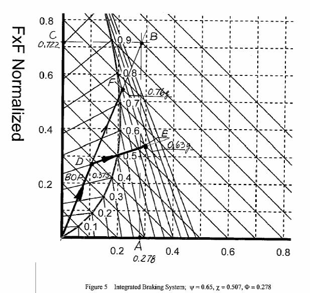
17 F xr /W = 0.335, or a = = 0.63g (Equation 17), indicating excellent agreement with our graphical solution shown in Figures 4 and INTEGRATED BRAKING For an integrated brake system application (usually) of the rear brake pedal applies onehalf of the front brake (one brake rotor only instead of two) along with full braking of the rear brake. The braking force distribution Φ is defined by the ratio of rear braking force divided by the total braking force: Φ = F xr /(F xf +F xr ) (21) The braking forces are determined with Equation 15 applied for both front and rear brake. For our exemplar motorcycle case we assume that the front dual cylinder brake caliper for one rotor has a wheel cylinder piston diameter of 1 in., an effective rotor radius r F = 6. 1 in., front tire radius R F = 12 in., a rear dual cylinder brake caliper wheel cylinder diameter of 1 in., an effective rear rotor radius of r R = 5.08 in., and rear tire radius R R = 13 in. All other brake components are assumed to be identical front and rear. The front cross-sectional area on both wheel cylinders is (2)(l) 2 (3.14)/(4) = 1.57 in 2. The cross-sectional area of the rear wheel cylinder area is (1) 2 (3. 14)/(4) = in 2. Substitution of the brake parameters usually different front to rear into Equation 21 yields Φ = (0.785)(5.08/13)/[(1.57)(6.1/12) + (0.785)(5.08/13)] = The result indicates the basic brake system layout is such that 27.8% of the total braking force is concentrated on the rear wheel. Plotting F xr /W = on the x-axis of Figure 5 (point A) and drawing a vertical line from there to the line of constant deceleration a = 1.0g yields point B. Drawing a horizontal line through B yields point C, the normalized front braking force F xf /W = = 1 - Φ. The braking operating line for the integrated brake system is obtained by drawing a straight line from the origin to point B (unless hydraulic brake line pressure modulating valves are used). Inspection of the braking forces diagram shows the following: The BOP moves from the origin along the inclined operating line until the BOP reaches the line of constant friction coefficient f conf = 0.5 at point D, where the front brake locks or the ABS system begins to modulate. The deceleration at point D is approximately a = 0.375g. If the driver continues to increase brake pedal force, the BOP moves along the line of front constant coefficient of friction to the right until it reaches point E at a deceleration of approximately 0.63g (same as in Section 7.3). If in our exemplar motorcycle case both front and rear tire-road friction coefficients had been identical, say f F = f R = 0.8, inspection of the braking forces diagram shows that the BOP would move passed point D and the optimum line until it reaches point F, that is, 17
18 18
19 the rear line of constant friction coefficient at f conr = 0.8 at a deceleration of approximately 0.76g. The rear brake would lock before the front slightly below optimum conditions of a = 0.8g. The exact deceleration at point D can be computed from the two straight lines intersecting at point D. One line is the line of constant rear friction coefficient f conr = 0.8 (Equation 20). The other line is the operating line of the form y = mx with its beginning at the origin, that is, b = 0. The slope m is determined from the brake balance as m = 0.722/0.278 = Solving F xf /W = F xr /W and Equation 20 simultaneously yields F xf /W = and F xr /W = 0.211, resulting in a deceleration of 0.76g OPERATOR ERRORS DURING EMERGENCY BRAKING This section is not intended to provide a complete review of test data and accident statistical records. Its objectives are to present some information in reference to the braking analysis discussed. Emergency in this section has reference to the operator and accident avoidance braking maneuvers where maximum braking effectiveness or deceleration is required OPERATOR ERROR The operator is not able to utilize the maximum tire-road friction available. Frequently, this error reveals itself when the operator applies the brakes hesitantly. In case of underbraking of the front brake the deceleration is significantly reduced. Lack of training and practice are often the reason. In many accidents involving motorcycle braking, the accident scene data show only a long rear tire brake mark, some times followed by a short front tire braking skid mark within a few feet of the point of impact. Even motorcycles equipped with ABS brakes are not fully utilized by inexperienced operators FRONT BRAKE LOCKUP PRIOR TO LOAD TRANSFER In the entire braking analysis presented in this article the assumption was made the load transfer from the rear wheel onto the front wheel occurs instantly without any time delay. However, the increase in front wheel normal force experiences a time delay caused by the significant compression of the front springs. Consequently, immediate and full application of the front brake may result in lockup due to a lack of front wheel dynamic normal force. The danger of front brake lockup and capsizing of the motorcycle under these conditions are correspondingly great. ABS braking systems as well as special front suspensions equipped with kinematic pitch adjustment eliminate or minimize the effects of time delay BRAKE SYSTEM FACTORS AFFECTING BRAKING EFFECTIVENESS 9.1 FRONT BRAKE SHIMMY (WOBBLE) Lateral run-out (LOR) greater than approximately 0.1 mm ( in.) of the front rotor causes the brake pad to rub against the high points of the disc when not braking, resulting 19
20 in non-uniform rotor thickness (disc thickness variation or DTV) around the circumference. When braking at moderate deceleration from higher speeds, DTV values greater than approximately 0.01 mm ( in.) will cause brake torque fluctuations resulting in hand brake lever oscillations as well as potential front end wobble BRAKE FADE Brake fade is defined as a decrease in brake factor (brake torque) due a decrease in pad/rotor coefficient of friction caused by increased brake temperature. For motorcycle brakes initial fading may be a safety problem. In particular, the initial fading problem exists for "green" (new) organic pad materials which have not yet experienced a certain upper brake temperature limit. The binder component of the pad may change to a vapor, partially separating the pad from the swept surface of the rotor while braking. The result is temporary decrease of the pad friction coefficient and corresponding decrease of the brake factor (brake torque) and braking effectiveness. Once the binder is fully vaporized, the brake pad friction coefficient stabilizes at its design level BRAKE FLUID VAPORIZATION Brake fluid vaporization occurs when the brake fluid in the front (or rear) caliper wheel cylinder exceeds the boiling temperature of the brake fluid. Brake fluid vapor assumes a significantly larger volume than liquid brake fluid, causing a compressible vapor pocket. The front (or rear) brake system cannot be pressurized effectively, resulting in partial or total front brake failure. The boiling temperature of brake fluid is a function of the type or quality of brake fluid used, and fluid contamination by water. Since brake fluid is hygroscopic it will absorb water naturally. Water will enter the brake system through the flexible brake hoses. Motorcycle brake maintenance must include regular brake fluid changes. References: 1. Accident Investigation Quarterly, Summer Accident Investigation Quarterly, Fall Brake Design and Safety, Rudolf Limpert, 2nd Edition, SAE International, Unfallrekonstruktion, Volume 2, Wolfgang Hugemann, autorenteamgbr, Note: The latest accident reconstruction software MARC 1 is available at no cost from the PC Brake website: under link to MARC
FRONTAL OFF SET COLLISION
 FRONTAL OFF SET COLLISION MARC1 SOLUTIONS Rudy Limpert Short Paper PCB2 2014 www.pcbrakeinc.com 1 1.0. Introduction A crash-test-on- paper is an analysis using the forward method where impact conditions
White Paper: The Physics of Braking Systems
 White Paper: The Physics of Braking Systems The Conservation of Energy The braking system exists to convert the energy of a vehicle in motion into thermal energy, more commonly referred to as heat. From
International Journal of Advance Engineering and Research Development. Design of Braking System of BAJA Vehicle
 Scientific Journal of Impact Factor (SJIF): 4.72 International Journal of Advance Engineering and Research Development Volume 4, Issue 11, November -2017 Design of Braking System of BAJA Vehicle Vivek
SHORT PAPER PCB OBLIQUE COLLISIONS ENGINEERING EQUATIONS, INPUT DATA AND MARC 1 APPLICATIONS. Dennis F. Andrews, Franco Gamero, Rudy Limpert
 SHORT PAPER PCB 5-2006 OBLIQUE COLLISIONS ENGINEERING EQUATIONS, INPUT DATA AND MARC 1 APPLICATIONS By: Dennis F. Andrews, Franco Gamero, Rudy Limpert PC-BRAKE, INC. 2006 www.pcbrakeinc.com 1 PURPOSE OF
SHORT PAPER PCB OBLIQUE COLLISIONS ENGINEERING EQUATIONS, INPUT DATA AND MARC 1 APPLICATIONS. Dennis F. Andrews, Franco Gamero, Rudy Limpert
 SHORT PAPER PCB 8-2006 OBLIQUE COLLISIONS ENGINEERING EQUATIONS, INPUT DATA AND MARC 1 APPLICATIONS By: Dennis F. Andrews, Franco Gamero, Rudy Limpert PC-BRAKE, INC. 2006 www.pcbrakeinc.com 1 PURPOSE OF
Improvement of Vehicle Dynamics by Right-and-Left Torque Vectoring System in Various Drivetrains x
 Improvement of Vehicle Dynamics by Right-and-Left Torque Vectoring System in Various Drivetrains x Kaoru SAWASE* Yuichi USHIRODA* Abstract This paper describes the verification by calculation of vehicle
BRAKE SYSTEM DESIGN AND THEORY
 RAKE SYSTEM DESIGN AND THEORY Aircraft brake systems perform multiple functions. They must be able to hold the aircraft back at full static engine run-up, provide adequate control during ground taxi operations,
Design and Validation of Hydraulic brake system for Utility Vehicle
 ISSN 2395-1621 Design and Validation of Hydraulic brake system for Utility Vehicle #1 K.M.Pavan, #2 Dr. A.G.Thakur 1 pavan56@yahoo.com 2 ajay_raja34@yahoo.com #12 Department of Mechanical Engineering,
FUNDAMENTAL PRINCIPLES
 FUNDAMENTAL PRINCIPLES Fundamental Principles The most important safety feature of an automobile is its brake system. The ability of a braking system to provide safe, repeatable stopping is the key to
Low Speed Rear End Crash Analysis
 Low Speed Rear End Crash Analysis MARC1 Use in Test Data Analysis and Crash Reconstruction Rudy Limpert, Ph.D. Short Paper PCB2 2015 www.pcbrakeinc.com e mail: prosourc@xmission.com 1 1.0. Introduction
SHORT PAPER PCB IN-LINE COLLISIONS ENGINEERING EQUATIONS, INPUT DATA AND MARC 1 APPLICATIONS. Dennis F. Andrews, Franco Gamero, Rudy Limpert
 SHORT PAPER PCB 3-2006 IN-LINE COLLISIONS ENGINEERING EQUATIONS, INPUT DATA AND MARC 1 APPLICATIONS By: Dennis F. Andrews, Franco Gamero, Rudy Limpert PC-BRAKE, INC. 2006 www.pcbrakeinc.com 1 PURPOSE OF
A Methodology to Investigate the Dynamic Characteristics of ESP Hydraulic Units - Part II: Hardware-In-the-Loop Tests
 A Methodology to Investigate the Dynamic Characteristics of ESP Hydraulic Units - Part II: Hardware-In-the-Loop Tests Aldo Sorniotti Politecnico di Torino, Department of Mechanics Corso Duca degli Abruzzi
MECA0494 : Braking systems
 MECA0494 : Braking systems Pierre Duysinx Research Center in Sustainable Automotive Technologies of University of Liege Academic Year 2017-2018 1 MECA0494 Driveline and Braking Systems Monday 23/10 (@ULG)
DEVELOPMENT OF HYDRAULIC BRAKE DESIGN SYSTEM APPLICATION
 DEVELOPMENT OF HYDRAULIC BRAKE DESIGN SYSTEM APPLICATION AMOGH DESHPANDE Department of Mechanical Engineering, VJTI, Matunga, Mumbai, India ABSTRACT The brakes which are actuated by the hydraulic pressure
COURSE LEARNING OUTCOMES
 COURSE LEARNING OUTCOMES No. Course Learning Outcome 1. 2. Compare working principle and identify advantages/disadvantages between the disc and drum brake systems used in passenger vehicles Analyze deceleration
Tech Tip: Trackside Tire Data
 Using Tire Data On Track Tires are complex and vitally important parts of a race car. The way that they behave depends on a number of parameters, and also on the interaction between these parameters. To
Transmission Error in Screw Compressor Rotors
 Purdue University Purdue e-pubs International Compressor Engineering Conference School of Mechanical Engineering 2008 Transmission Error in Screw Compressor Rotors Jack Sauls Trane Follow this and additional
STUDENT ACTIVITY SHEET Name Period Fire Hose Friction Loss The Varying Variables for the One That Got Away Part 1
 STUDENT ACTIVITY SHEET Name Period Fire Hose Friction Loss The Varying Variables for the One That Got Away Part 1 The questions: How does Friction Loss change with the quality of the fire hose? How does
MOTOR VEHICLE HANDLING AND STABILITY PREDICTION
 MOTOR VEHICLE HANDLING AND STABILITY PREDICTION Stan A. Lukowski ACKNOWLEDGEMENT This report was prepared in fulfillment of the Scholarly Activity Improvement Fund for the 2007-2008 academic year funded
An Introduction to Brake Systems
 An Introduction to Brake Systems SAE Brake Colloquium October 6th 2002 DaimlerChrysler This presentation was originally created as a one hour lecture class. This is not intended to be a stand alone text
ISO INTERNATIONAL STANDARD. Road vehicles Brake lining friction materials Friction behaviour assessment for automotive brake systems
 INTERNATIONAL STANDARD ISO 26867 First edition 2009-07-01 Road vehicles Brake lining friction materials Friction behaviour assessment for automotive brake systems Véhicules routiers Matériaux de friction
Design and Integration of Suspension, Brake and Steering Systems for a Formula SAE Race Car
 Design and Integration of Suspension, Brake and Steering Systems for a Formula SAE Race Car Mark Holveck 01, Rodolphe Poussot 00, Harris Yong 00 Final Report May 5, 2000 MAE 340/440 Advisor: Prof. S. Bogdonoff
Analysis and evaluation of a tyre model through test data obtained using the IMMa tyre test bench
 Vehicle System Dynamics Vol. 43, Supplement, 2005, 241 252 Analysis and evaluation of a tyre model through test data obtained using the IMMa tyre test bench A. ORTIZ*, J.A. CABRERA, J. CASTILLO and A.
Research in hydraulic brake components and operational factors influencing the hysteresis losses
 Research in hydraulic brake components and operational factors influencing the hysteresis losses Shreyash Balapure, Shashank James, Prof.Abhijit Getem ¹Student, B.E. Mechanical, GHRCE Nagpur, India, ¹Student,
BRAKES Driver Information Getting the best from your car
 S i Driver Information Getting the best from your car STOPPING FROM THE START Early brakes used a mechanical system of levers and cables to apply braking friction to the wheels. This was adequate when
BRAKE SYSTEM FUNDAMENTALS KARAN BHARDIYA ASSISTANT MANAGER -R&D ENDURANCE TECHNOLOGIES PVT.LTD. DISC BRAKES
 BRAKE SYSTEM FUNDAMENTALS KARAN BHARDIYA ASSISTANT MANAGER -R&D ENDURANCE TECHNOLOGIES PVT.LTD. DISC BRAKES AUTOMOTIVE BRAKING SYSTEMS How brakes manufacturing industry is different then rest of the automotive
Simplified Vehicle Models
 Chapter 1 Modeling of the vehicle dynamics has been extensively studied in the last twenty years. We extract from the existing rich literature [25], [44] the vehicle dynamic models needed in this thesis
C. Brake pads Replaceable friction surfaces that are forced against the rotor by the caliper piston.
 BRAKES UNIT 1: INTRODUCTION TO BRAKE SYSTEMS LESSON 1: FUNDAMENTAL PRINCIPLES OF BRAKE SYSTEMS I. Terms and definitions A. Brake fading Loss of brakes, usually due to heat. B. Brake lining Material mounted
WEEK 4 Dynamics of Machinery
 WEEK 4 Dynamics of Machinery References Theory of Machines and Mechanisms, J.J.Uicker, G.R.Pennock ve J.E. Shigley, 2003 Prof.Dr.Hasan ÖZTÜRK 1 DYNAMICS OF RECIPROCATING ENGINES Prof.Dr.Hasan ÖZTÜRK The
LCN ACN-PCN
 7.0 PAVEMENT DATA 7.1 General Information 7.2 Footprint 7.3 Maximum Pavement Loads 7.4 Landing Gear Loading on Pavement 7.5 Flexible Pavement Requirements 7.6 Flexible Pavement Requirements, LCN Conversion
Simple Gears and Transmission
 Simple Gears and Transmission Simple Gears and Transmission page: of 4 How can transmissions be designed so that they provide the force, speed and direction required and how efficient will the design be?
Review on Handling Characteristics of Road Vehicles
 RESEARCH ARTICLE OPEN ACCESS Review on Handling Characteristics of Road Vehicles D. A. Panke 1*, N. H. Ambhore 2, R. N. Marathe 3 1 Post Graduate Student, Department of Mechanical Engineering, Vishwakarma
LCN ACN-PCN
 7.0 PAVEMENT DATA 7.1 General Information 7.2 Footprint 7.3 Maximum Pavement Loads 7.4 Landing Gear Loading on Pavement 7.5 Flexible Pavement Requirements 7.6 Flexible Pavement Requirements, LCN Conversion
HECU Clock frequency 32 MHz 50 MHz Memory 128 KB 512 KB Switch Orifice Orifice. Operating temperature - 40 C to 150 C - 40 C to 150 C
 489000 113 1. SPECIFICATION Unit Description Specification ABS ESP HECU Clock frequency 32 MHz 50 MHz Memory 128 KB 512 KB Switch Orifice Orifice Wheel speed sensor ABS / ESP CBS Operating temperature
Accident Reconstruction & Vehicle Data Recovery Systems and Uses
 Research Engineers, Inc. (919) 781-7730 7730 Collision Analysis Engineering Animation Accident Reconstruction & Vehicle Data Recovery Systems and Uses Bill Kluge Thursday, May 21, 2009 Accident Reconstruction
Motor Type Selection. maxon s EC 4-pole brushless motors
 Motor Type Selection Parameters that define a motor type are the mechanical output power, the shaft bearing system, the commutation system used, and the possible combinations with gearheads and sensors.
SIMRET makes Heavy Vehicle Brake Testing easy!
 SIMRET makes Heavy Vehicle Brake Testing easy! The traditional way to measure brake performance of a vehicle has been to its measure stopping distance. In other words, the distance travelled between applying
ABS keeps the vehicle steerable, even during an emergency braking
 ABS keeps the vehicle steerable, even during an emergency braking under all road conditions 1 Contents! Safety systems in vehicles! Why do you need ABS?! How does ABS work?! What are the benefits of ABS?!
8. Other system and brake theories
 8. Other system and brake theories Objective To understand the limiting valve, proportioning valve, load sensing proportioning valve and brake theories, which were used immediately before the development
Application of DSS to Evaluate Performance of Work Equipment of Wheel Loader with Parallel Linkage
 Technical Papers Toru Shiina Hirotaka Takahashi The wheel loader with parallel linkage has one remarkable advantage. Namely, it offers a high degree of parallelism to its front attachment. Loaders of this
SAE Baja - Drivetrain
 SAE Baja - Drivetrain By Ricardo Inzunza, Brandon Janca, Ryan Worden Team 11 Engineering Analysis Document Submitted towards partial fulfillment of the requirements for Mechanical Engineering Design I
Discussion Paper. Effect of Anti-Squat Adjustment in Solid Axle 4 Link Rear Suspension Systems
 Discussion Paper Effect of Anti-Squat Adjustment in Solid Axle 4 Link Rear Suspension Systems Example used is Commodore 1990 VG utility fitted with Whiteline KTA103 adjustable upper trailing arms. Prepared
Lateral Directional Flight Considerations
 Lateral Directional Flight Considerations This section discusses the lateral-directional control requirements for various flight conditions including cross-wind landings, asymmetric thrust, turning flight,
Design and Analysis of suspension system components
 Design and Analysis of suspension system components Manohar Gade 1, Rayees Shaikh 2, Deepak Bijamwar 3, Shubham Jambale 4, Vikram Kulkarni 5 1 Student, Department of Mechanical Engineering, D Y Patil college
Transmitted by the expert from the European Commission (EC) Informal Document No. GRRF (62nd GRRF, September 2007, agenda item 3(i))
 Informal Document No. GRRF (62nd GRRF, September 2007, agenda item 3(i))") Transmitted by the expert from the European Commission (EC) Informal Document No. GRRF-62-31 (62nd GRRF, 25-28 September 2007, agenda item 3(i)) Introduction of Brake Assist Systems to Regulation No. 13-H
Transmitted by the expert from the European Commission (EC) Informal Document No. GRRF-62-31 (62nd GRRF, 25-28 September 2007, agenda item 3(i)) Introduction of Brake Assist Systems to Regulation No. 13-H
2. Write the expression for estimation of the natural frequency of free torsional vibration of a shaft. (N/D 15)
") ME 6505 DYNAMICS OF MACHINES Fifth Semester Mechanical Engineering (Regulations 2013) Unit III PART A 1. Write the mathematical expression for a free vibration system with viscous damping. (N/D 15) Viscous
ME 6505 DYNAMICS OF MACHINES Fifth Semester Mechanical Engineering (Regulations 2013) Unit III PART A 1. Write the mathematical expression for a free vibration system with viscous damping. (N/D 15) Viscous
SLIP CONTROL AT SMALL SLIP VALUES FOR ROAD VEHICLE BRAKE SYSTEMS
 PERIODICA POLYTECHNICA SER MECH ENG VOL 44, NO 1, PP 23 30 (2000) SLIP CONTROL AT SMALL SLIP VALUES FOR ROAD VEHICLE BRAKE SYSTEMS Péter FRANK Knorr-Bremse Research & Development Institute, Budapest Department
An Adaptive Nonlinear Filter Approach to Vehicle Velocity Estimation for ABS
 An Adaptive Nonlinear Filter Approach to Vehicle Velocity Estimation for ABS Fangjun Jiang, Zhiqiang Gao Applied Control Research Lab. Cleveland State University Abstract A novel approach to vehicle velocity
White Paper. Phone: Fax: Advance Lifts, Inc. All rights reserved.
 White Paper TURNTABLE AppLicATioN GUidE This section covers the full range of turntables manufactured by Advance Lifts. The basic information necessary to select an appropriate turntable for an application
The Theoretical Analysis of Test Result s Errors for the Roller Type Automobile Brake Tester
 The Theoretical Analysis of Test Result s Errors for the Roller Type Automobile Brake Tester Jun Li, Xiaojing Zha, and Dongsheng Wu School of Mechanical and Electronic Engineering, East China Jiaotong
Racing Tires in Formula SAE Suspension Development
 The University of Western Ontario Department of Mechanical and Materials Engineering MME419 Mechanical Engineering Project MME499 Mechanical Engineering Design (Industrial) Racing Tires in Formula SAE
Hybrid Architectures for Automated Transmission Systems
 1 / 5 Hybrid Architectures for Automated Transmission Systems - add-on and integrated solutions - Dierk REITZ, Uwe WAGNER, Reinhard BERGER LuK GmbH & Co. ohg Bussmatten 2, 77815 Bühl, Germany (E-Mail:
Skid against Curb simulation using Abaqus/Explicit
 Visit the SIMULIA Resource Center for more customer examples. Skid against Curb simulation using Abaqus/Explicit Dipl.-Ing. A. Lepold (FORD), Dipl.-Ing. T. Kroschwald (TECOSIM) Abstract: Skid a full vehicle
DESIGN, ANALYSIS AND FABRICATION OF BRAKING SYSTEM WITH REAR INBOARD BRAKES IN BAJA ATV
 DESIGN, ANALYSIS AND FABRICATION OF BRAKING SYSTEM WITH REAR INBOARD BRAKES IN BAJA ATV Aman Sharma 1, Prakhar Amrute 2, Suryakant Singh Thakur 3, Jatin Shrivastav 4 1,2,3,4Department of Mechanical Engineering,
1 Summary PROPORTIONAL RESPONSE TECHNICAL SUMMARY. Contents
 HABIT WHITE PAPER PROPORTIONAL RESPONSE TECHNICAL SUMMARY Contents 1 Summary 1 2 Suspension for Mountain Bikes 2 3 Proportional Response 10 4 Experimental Validation of Suspension Response 12 5 Size Specific
TECHNICAL NOTE. NADS Vehicle Dynamics Typical Modeling Data. Document ID: N Author(s): Chris Schwarz Date: August 2006
: Chris Schwarz Date: August 2006") TECHNICAL NOTE NADS Vehicle Dynamics Typical Modeling Data Document ID: N06-017 Author(s): Chris Schwarz Date: August 2006 National Advanced Driving Simulator 2401 Oakdale Blvd. Iowa City, IA 52242-5003
TECHNICAL NOTE NADS Vehicle Dynamics Typical Modeling Data Document ID: N06-017 Author(s): Chris Schwarz Date: August 2006 National Advanced Driving Simulator 2401 Oakdale Blvd. Iowa City, IA 52242-5003
DEVELOPMENT OF A LAP-TIME SIMULATOR FOR A FSAE RACE CAR USING MULTI-BODY DYNAMIC SIMULATION APPROACH
 International Journal of Mechanical Engineering and Technology (IJMET) Volume 9, Issue 7, July 2018, pp. 409 421, Article ID: IJMET_09_07_045 Available online at http://www.iaeme.com/ijmet/issues.asp?jtype=ijmet&vtype=9&itype=7
Road Accident Investigation. specialists in the UK who use mathematics to reconstruct the probable manoeuvres
 Road Accident Investigation The phrases the police service and using mathematics are not usually associated with each other. There are however a small number of police officers and other specialists in
STEALTH INTERNATIONAL INC. DESIGN REPORT #1001 IBC ENERGY DISSIPATING VALVE FLOW TESTING OF 12 VALVE
 STEALTH INTERNATIONAL INC. DESIGN REPORT #1001 IBC ENERGY DISSIPATING VALVE FLOW TESTING OF 12 VALVE 2 This report will discuss the results obtained from flow testing of a 12 IBC valve at Alden Research
Analysis of Parametric Studies on the Impact of Piston Velocity Profile On the Performance of a Single Cylinder Diesel Engine
 IOSR Journal of Mechanical and Civil Engineering (IOSR-JMCE) e-issn: 2278-1684,p-ISSN: 2320-334X, Volume 12, Issue 2 Ver. II (Mar - Apr. 2015), PP 81-85 www.iosrjournals.org Analysis of Parametric Studies
SURFACE VEHICLE RECOMMENDED PRACTICE
 SURFACE VEHICLE RECOMMENDED PRACTICE J1095 Issued 1982-06 Revised 2003-03 REV. MAR2003 Superseding J1095 MAR1995 Spoke Wheels and Hub Fatigue Test Procedures 1. Scope This SAE Recommended Practice provides
Design Evaluation and Optimization of a Disc Brake
 Design Evaluation and Optimization of a Disc Brake Abstract: Susmitha Sankatala M.Tech (Production), Department of Mechanical Engineering, Sree Vaanmayi Institute of Engineering & Technology. The disc
UNDERGROUND MINING. Mine hoist disc brake systems Improved safety, availability and productivity
 UNDERGROUND MINING Mine hoist disc brake systems Improved safety, availability and productivity 2 MINE HOIST DISC BRAKE SYSTEMS IMPROVED SAFETY, AVAILABILITY AND PRODUCTIVITY Mine hoist disc brake systems
A Brake Pad Wear Control Algorithm for Electronic Brake System
 Advanced Materials Research Online: 2013-05-14 ISSN: 1662-8985, Vols. 694-697, pp 2099-2105 doi:10.4028/www.scientific.net/amr.694-697.2099 2013 Trans Tech Publications, Switzerland A Brake Pad Wear Control
Familiarize yourself with the pressure loss phenomenon. The Discussion of this exercise covers the following point:
 Exercise 3-2 Pressure Loss EXERCISE OBJECTIVE Familiarize yourself with the pressure loss phenomenon. DISCUSSION OUTLINE The Discussion of this exercise covers the following point: Pressure loss Major
NEW CAR TIPS. Teaching Guidelines
 NEW CAR TIPS Teaching Guidelines Subject: Algebra Topics: Patterns and Functions Grades: 7-12 Concepts: Independent and dependent variables Slope Direct variation (optional) Knowledge and Skills: Can relate
Components of Hydronic Systems
 Valve and Actuator Manual 977 Hydronic System Basics Section Engineering Bulletin H111 Issue Date 0789 Components of Hydronic Systems The performance of a hydronic system depends upon many factors. Because
Extracting Tire Model Parameters From Test Data
 WP# 2001-4 Extracting Tire Model Parameters From Test Data Wesley D. Grimes, P.E. Eric Hunter Collision Engineering Associates, Inc ABSTRACT Computer models used to study crashes require data describing
The Mark Ortiz Automotive
 August 2004 WELCOME Mark Ortiz Automotive is a chassis consulting service primarily serving oval track and road racers. This newsletter is a free service intended to benefit racers and enthusiasts by offering
Rotational Kinematics and Dynamics Review
 Rotational Kinematics and Dynamics Review 1. The Earth takes slightly less than one day to complete one rotation about the axis passing through its poles. The actual time is 8.616 10 4 s. Given this information,
ABS. Prof. R.G. Longoria Spring v. 1. ME 379M/397 Vehicle System Dynamics and Control
 ABS Prof. R.G. Longoria Spring 2002 v. 1 Anti-lock Braking Systems These systems monitor operating conditions and modify the applied braking torque by modulating the brake pressure. The systems try to
Technical Report Con Rod Length, Stroke, Piston Pin Offset, Piston Motion and Dwell in the Lotus-Ford Twin Cam Engine. T. L. Duell.
 Technical Report - 1 Con Rod Length, Stroke, Piston Pin Offset, Piston Motion and Dwell in the Lotus-Ford Twin Cam Engine by T. L. Duell May 24 Terry Duell consulting 19 Rylandes Drive, Gladstone Park
MODELING SUSPENSION DAMPER MODULES USING LS-DYNA
 MODELING SUSPENSION DAMPER MODULES USING LS-DYNA Jason J. Tao Delphi Automotive Systems Energy & Chassis Systems Division 435 Cincinnati Street Dayton, OH 4548 Telephone: (937) 455-6298 E-mail: Jason.J.Tao@Delphiauto.com
LEAD SCREWS 101 A BASIC GUIDE TO IMPLEMENTING A LEAD SCREW ASSEMBLY FOR ANY DESIGN
 LEAD SCREWS 101 A BASIC GUIDE TO IMPLEMENTING A LEAD SCREW ASSEMBLY FOR ANY DESIGN Released by: Keith Knight Kerk Products Division Haydon Kerk Motion Solutions Lead Screws 101: A Basic Guide to Implementing
COMPACT CYLINDER CYLINDER FORCE AND WEIGHT TABLE BASE WEIGHT EFFECTIVE AREA
 CRS COMPACT CYLINDER STROKE TOLERANCE TEMPERATURE LIMITS VELOCITY LIFE EXPECTANCY SERIES CRS 1 psi min to 15 psi max at zero load [.7 bar min to 1 bar max] air.31 inch [.8 mm] -2 to +18 F [-28 to +82 C]
Passenger Vehicle Steady-State Directional Stability Analysis Utilizing EDVSM and SIMON
 WP# 4-3 Passenger Vehicle Steady-State Directional Stability Analysis Utilizing and Daniel A. Fittanto, M.S.M.E., P.E. and Adam Senalik, M.S.G.E., P.E. Ruhl Forensic, Inc. Copyright 4 by Engineering Dynamics
Your Brakes. Fundamentals of Braking
 B U S S E R V I C E, I N C. Your Brakes Fundamentals of Braking There are a variety of mechanical forces and physical components that make up the braking system of your coach. The forces that effect your
Suspension systems and components
 Suspension systems and components 2of 42 Objectives To provide good ride and handling performance vertical compliance providing chassis isolation ensuring that the wheels follow the road profile very little
Torque steer effects resulting from tyre aligning torque Effect of kinematics and elastokinematics
 P refa c e Tyres of suspension and drive 1.1 General characteristics of wheel suspensions 1.2 Independent wheel suspensions- general 1.2.1 Requirements 1.2.2 Double wishbone suspensions 1.2.3 McPherson
AT 2303 AUTOMOTIVE POLLUTION AND CONTROL Automobile Engineering Question Bank
 AT 2303 AUTOMOTIVE POLLUTION AND CONTROL Automobile Engineering Question Bank UNIT I INTRODUCTION 1. What are the design considerations of a vehicle?(jun 2013) 2..Classify the various types of vehicles.
Brake Systems. Introduction
 Brake Systems Figure 1. A Typical Brake System Introduction The brake system (Figure 1) is designed to slow and halt the motion of a vehicle. To do that, various components within a hydraulic brake system
A double-wishbone type suspension is used in the front. A multi-link type suspension is used in the rear. Tread* mm (in.) 1560 (61.
 1560 (61.") CHASSIS SUSPENSION AND AXLE CH-69 SUSPENSION AND AXLE SUSPENSION 1. General A double-wishbone type suspension is used in the front. A multi-link type suspension is used in the rear. 08D0CH111Z Specifications
CHASSIS SUSPENSION AND AXLE CH-69 SUSPENSION AND AXLE SUSPENSION 1. General A double-wishbone type suspension is used in the front. A multi-link type suspension is used in the rear. 08D0CH111Z Specifications
A Literature Review and Study on 4 Wheel Steering Mechanisms
 2018 IJSRST Volume 4 Issue 3 Print ISSN : 2395-6011 Online ISSN: 2395-602X National Conference on Advances in Engineering and Applied Science (NCAEAS) 29 th January 2018 Organized by : Anjuman College
Design & Development of Regenerative Braking System at Rear Axle
 International Journal of Advanced Mechanical Engineering. ISSN 2250-3234 Volume 8, Number 2 (2018), pp. 165-172 Research India Publications http://www.ripublication.com Design & Development of Regenerative
Chapter 10 Parametric Studies
 Chapter 10 Parametric Studies 10.1. Introduction The emergence of the next-generation high-capacity commercial transports [51 and 52] provides an excellent opportunity to demonstrate the capability of
Investigating the impact of track gradients on traction energy efficiency in freight transportation by railway
 Energy and Sustainability III 461 Investigating the impact of track gradients on traction energy efficiency in freight transportation by railway G. Bureika & G. Vaičiūnas Department of Railway Transport,
Sport Shieldz Skull Cap Evaluation EBB 4/22/2016
 Summary A single sample of the Sport Shieldz Skull Cap was tested to determine what additional protective benefit might result from wearing it under a current motorcycle helmet. A series of impacts were
CHAPTER 4 MODELING OF PERMANENT MAGNET SYNCHRONOUS GENERATOR BASED WIND ENERGY CONVERSION SYSTEM
 47 CHAPTER 4 MODELING OF PERMANENT MAGNET SYNCHRONOUS GENERATOR BASED WIND ENERGY CONVERSION SYSTEM 4.1 INTRODUCTION Wind energy has been the subject of much recent research and development. The only negative
STUDY OF ROLL CENTER SAURABH SINGH *, SAGAR SAHU ** ABSTRACT
 STUDY OF ROLL CENTER SAURABH SINGH *, SAGAR SAHU ** *, ** Mechanical engineering, NIT B ABSTRACT As our solar car aims to bring new green technology to cope up with the greatest challenge of modern era
Keywords: driver support and platooning, yaw stability, closed loop performance
 CLOSED LOOP PERFORMANCE OF HEAVY GOODS VEHICLES Dr. Joop P. Pauwelussen, Professor of Mobility Technology, HAN University of Applied Sciences, Automotive Research, Arnhem, the Netherlands Abstract It is
Mathematical Modelling and Simulation Of Semi- Active Suspension System For An 8 8 Armoured Wheeled Vehicle With 11 DOF
 Mathematical Modelling and Simulation Of Semi- Active Suspension System For An 8 8 Armoured Wheeled Vehicle With 11 DOF Sujithkumar M Sc C, V V Jagirdar Sc D and MW Trikande Sc G VRDE, Ahmednagar Maharashtra-414006,
SPMM OUTLINE SPECIFICATION - SP20016 issue 2 WHAT IS THE SPMM 5000?
 SPMM 5000 OUTLINE SPECIFICATION - SP20016 issue 2 WHAT IS THE SPMM 5000? The Suspension Parameter Measuring Machine (SPMM) is designed to measure the quasi-static suspension characteristics that are important
CHAPTER 6 MECHANICAL SHOCK TESTS ON DIP-PCB ASSEMBLY
 135 CHAPTER 6 MECHANICAL SHOCK TESTS ON DIP-PCB ASSEMBLY 6.1 INTRODUCTION Shock is often defined as a rapid transfer of energy to a mechanical system, which results in a significant increase in the stress,
1.3 Research Objective
 1.3 Research Objective This research project will focus on a solution package that can facilitate the following objectives: 1. A better delineation of the no-passing zone, in particular the danger zone,
ECH 4224L Unit Operations Lab I Fluid Flow FLUID FLOW. Introduction. General Description
 FLUID FLOW Introduction Fluid flow is an important part of many processes, including transporting materials from one point to another, mixing of materials, and chemical reactions. In this experiment, you
Study of the Performance of a Driver-vehicle System for Changing the Steering Characteristics of a Vehicle
 20 Special Issue Estimation and Control of Vehicle Dynamics for Active Safety Research Report Study of the Performance of a Driver-vehicle System for Changing the Steering Characteristics of a Vehicle
III B.Tech I Semester Supplementary Examinations, May/June
 Set No. 1 III B.Tech I Semester Supplementary Examinations, May/June - 2015 1 a) Derive the expression for Gyroscopic Couple? b) A disc with radius of gyration of 60mm and a mass of 4kg is mounted centrally
Assignment 4:Rail Analysis and Stopping/Passing Distances
 CEE 3604: Introduction to Transportation Engineering Fall 2011 Date Due: September 26, 2011 Assignment 4:Rail Analysis and Stopping/Passing Distances Instructor: Trani Problem 1 The basic resistance of
Validation of Equations for Motorcycle and Rider Lean on a Curve
 2015-01-1422 Published 04/14/2015 Copyright 2015 SAE International doi:10.4271/2015-01-1422 saetransaf.saejournals.org Validation of Equations for Motorcycle and Rider Lean on a Curve Neal Carter, Nathan
Analysis of Tire Rub Rail Interaction
 Analysis of Tire Rub Rail Interaction Dirk Smith, Ph.D., P.E. Rimkus Consulting Group, Inc. Abstract On December 20, 2010, a Mine Safety and Health Administration (MSHA) inspector issued a citation at