OWNER/OPERATOR S MANUAL & PARTS LIST KH150 AUGER DRIVE
|
|
|
- Theresa Baldwin
- 6 years ago
- Views:
Transcription


1 OWNER/OPERATOR S MANUAL & PARTS LIST KH150 AUGER DRIVE Revised
2 Orrville, OH TO THE OWNER Product Identification If you need to contact an Authorized Ventrac Dealer for information on servicing your product, always provide the Product Model and Serial numbers. Please fill in the following information for future reference. See picture below to find the location of the identification number. Record them in the spaces provided below. Date of Purchase: Month Day Year Dealer: Dealer Address: Dealer Phone Number: Dealer FAX Number: Model # (A): Serial # (B): Affix Part/Serial Number label here ii Venture Products Inc. reserves the right to make changes in design or specifications without obligation to make like changes on previously manufactured products.
3 TABLE OF CONTENTS INTRODUCTION SECTION A Description & Specifications A-1 SAFETY SECTION B Safety Symbols B-1 Decals B-2 General Safety Procedures B-3 Safety Operation & Techniques B-4 SETUP & OPERATION SECTION C Valve Kit C-1 Auger Drive C-2 & 3 MAINTENANCE & SERVICE SECTION D Maintenance D-1 PARTS & ILLUSTRATED DRAWINGS SECTION E Hydraulic Valve Kit E-1 & 2 Posthole Drive Frame E-3 & 4 Augers & Drives E-5 & 6 WARRANTY iii
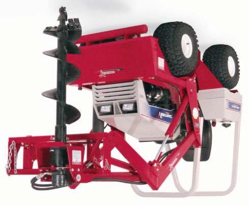
4 INTRODUCTION Product Description KH150 AUGER DRIVE The KH150 auger drive is an attachment, designed to give you, the owner, more versatility with your Ventrac tractor and versa-loader. The auger drive mounts to the KH500 Loader and provides the ability to drill holes for posts or poles and for transplanting trees. The standard auger sizes are 6, 9, 12, 15, 18, and 24 inches in diameter. The tree ball auger sizes are 24 and 30 inches in diameter. Two different motors are available for the auger drive. The fast drive motor can be used with augers up to 12 inches in diameter. Augers over 12 inches must use the slow drive motor. The maximum depth of the bore for standard augers is 42 inches deep. A 12 inch auger extension is available for added depth. Ventrac KH500 Specifications Overall Height with Standard Auger inches Overall Width inches Overall Length inches Weight without Auger pounds Boring Depth with Standard Auger inches Boring Depth with Auger Extension inches Hole Diameter (Fast Drive) inches Hole Diameter (Slow Drive) inches Fast Drive RPM (3200 Tractor RPM) RPM Slow Drive RPM (3200 Tractor RPM) RPM Valve Gallons/Minute at 3200 RPM GPM A-1
5 SAFETY ATTENTION: This symbol identifies potential health and safety hazards. It marks safety precautions. Your safety and the safety of others is involved. SIGNAL WORD DEFINITIONS Indicates an imminently hazardous situation which, if not avoided, will result in death or serious injury. This signal word is limited to the most extreme cases. Indicates a potentially hazardous situation which, if not avoided, could result in death or serious injury. Indicates a potentially hazardous situation which, if not avoided, may result in minor or moderate injury and/or property damage. It may also be used to alert against unsafe practices. B-1

6 SAFETY Safety Decals The following decal must be maintained on your Ventrac posthole drive attachment. If any decals are faded or missing, contact your dealer promptly for replacements. A Decal Page & Location Description Part Number A E-3, #13 Danger - Rotating Auger B-2
7 SAFETY General Safety Procedures for Ventrac Tractors, Attachments, & Accessories Read and understand the operator s manual before operating this equipment. Observe and follow all safety decals. DO NOT let children or any untrained person operate the tractor or attachment. Make sure that all operators of this equipment are thoroughly trained in using it safely. Never allow additional riders on the tractor or attachments. DO NOT operate tractor or attachments if you are under the influence of alcohol, drugs, or medication that may impair judgment or cause drowsiness, or if you are not feeling well. Operate all controls from the operator s seat only. Before operating equipment, make sure all shields are in place and fastened. Ensure the attachment or accessory is locked or fastened securely to the tractor before operating. See tractor manual for locking procedure. Ensure that all bystanders are clear of the tractor and attachment before operating. Be especially careful and observant if other people are present. Never assume that bystanders will remain where you last saw them. Always look in the direction the tractor is moving. Never direct the discharge of any attachment in the direction of people, animals, buildings, vehicles, or objects of value. Stop operation immediately at any sign of equipment failure and correct the problem before continuing to operate. An unusual noise can be a warning of equipment failure or a sign that maintenance is required. Before adjusting, cleaning, lubricating, or changing parts on the tractor or attachment, engage the parking brake, lower the attachment to the ground, stop the engine, and remove the ignition key. To prevent the risk of uncontrolled equipment movement on tractors equipped with 2 speed axles, always shift the transaxle range with the tractor stationary on level ground and with the parking brake engaged. If equipment is to be left unattended, engage the parking brake, lower the attachment to the ground, stop the engine, and remove the ignition key. B-3
8 SAFETY KH150 Safety Procedures Before making any repairs or adjustments, lower attachment to the ground, set parking brake, shut the engine off, and remove the key. Read and understand the operator s manual before operating this equipment. Serious injury or death can occur from improper use of this auger. Stay away from the auger when it is turning. Keep others away from auger. Rear counterweight must be used when operating loader and auger drive. Call before you dig. If there is any possibility of buried cables or gas lines in the area you are working, call the your local utilities before digging. There should be an 800 number to call listed in the front of your telephone directory. B-4
using 5/16 x 3/4 bolts and flange nuts. 2.")
 that connects the pump to the joystick valve, thread through the grommet and onto valve fitting (Fig 2b)")
 using two 5/16 x 3/4 bolts and flange nuts along with a 1/4 x 1/2 bolt, washer, and flange nut. 6.")
9 SETUP & OPERATION Setup of Valve Kit: 1. Fasten valve mounting plate to the loader frame as shown (Fig 1&2)using 5/16 x 3/4 bolts and flange nuts. 2. Install rubber grommet in slot in loader frame. (Fig 2a) 3. Remove pressure line hose (Fig 1a) that connects the pump to the joystick valve, thread through the grommet and onto valve fitting (Fig 2b) inside the loader frame. 4. Install new 1/2 hose as shown. (Fig 1b) Fig 1 Fig 2 2b 1b 1a 2a 5. Mount quick coupler bracket (Fig 3) using two 5/16 x 3/4 bolts and flange nuts along with a 1/4 x 1/2 bolt, washer, and flange nut. 6. Fasten hoses to welded fittings in coupler bracket. (Fig 3) Fig 3 Operation of Valve: 1. The valve and auger drive hoses should be routed so that moving the lever down rotates the auger clockwise to dig. 2. Wipe the quick couplers clean before coupling to auger drive. C-1

 by removing 4-3/8 x 3/4 bolts. 5. Remove the bolt plugs and cap (4b) from the top of the gearbox and pour in the supplied 75W-140 synthetic gear oil (12-12.5 oz.). (See figure 4) 4a Fig 4 Add oil here 4c 4b Fig 5 6.")

10 SETUP & OPERATION Setup of Auger Drive 1. Attach the main frame to the loader toolbar. Raise the loader so the top of the frame is approximately 4 feet off the floor. The 1-1/4 pivot tube should be parallel to the floor. 2. Insert the yoke bolt into the tube on top of the frame and install the 1-1/4 locknut. Do not over tighten the nut against the tube. The yoke should swing freely. 3. Remove the bolts (4c) from the auger drive mount, and bolt the drive mount to the yoke. (See figures 5& 6, also page E-3) 4. Remove the motor mount plate (4a) by removing 4-3/8 x 3/4 bolts. 5. Remove the bolt plugs and cap (4b) from the top of the gearbox and pour in the supplied 75W-140 synthetic gear oil ( oz.). (See figure 4) 4a Fig 4 Add oil here 4c 4b Fig 5 6. Install the o-ring onto the motor and seat into o-ring groove. 7. Set the motor on the gearbox with the hose ports turned to the front. Install the motor mount plate on top of the motor flange and reinstall the 3/8 x 3/4 bolts removed earlier. Do not tighten. 8. Apply thread lock or a quality thread sealer to 6a 4) 1/2 x 1-1/2 bolts and bolt the motor plate and motor to the gearbox. Torque to foot-pounds. (See figures 5& 6) 9. Tighten the 4-3/8 x 3/4 bolts holding the motor plate to the auger drive frame. 10. Remove the plugs from the hydraulic motor and install the hydraulic fittings. 11.Install the hoses onto the motor fittings as shown in figure 6. 6a is the hose with the male quick coupler. 6b is the hose with the female quick coupler. Fig 6 6b C-2

11 SETUP & OPERATION Operating Techniques and Tips: Move the valve handle down to start auger drive. Lower the auger into the soil to begin digging. In some soil conditions, the loader arms can be put in float while digging. This allows the auger to drill into the soil at its own speed. When digging in hard, stony soil or where tree roots are present, slowly lowering the loader arms manually may be required. If the auger becomes jammed on a rock or tree root, move the valve handle to the upper position to reverse the auger rotation and back it away from the object on which it is caught. When storing or transporting the auger drive, lift the rotation latch (Figure 7) and swivel the auger to the opposite side of the frame. Wrap the chain around the auger and secure to the chain hook. Fig 7 Always wait for parts to stop moving and lower the auger to the ground before dismounting from the tractor. CAUTION: Always shift transaxle range with the tractor parked on LEVEL ground. Never shift on a slope since all hydraulic braking capacity will be lost during the shifting process. Different circumstances and situations can occur for which the operator must determine a safe way to operate the tractor and auger drive. Always follow safety procedures and always use common sense. Approach every task with consideration for your safety as well as for the safety of anyone who happens to be near the work area. Make sure that all operators of this equipment are thoroughly trained in using it safely. C-3
12 MAINTENANCE & SERVICE Maintenance Grease the fitting on the drive swivel every 50 hours. The gear box is sealed, so the oil level does not need to be checked unless the gear box is leaking. Check the gear box for leaks before and after each use. Store auger drive in a clean dry environment. When storing auger drive, do not allow quick couplers to lay on the ground. Clean the quick couplers each time before they are reconnected. D-1
13 PARTS MANUAL KH150
14 PARTS ILLUSTRATED DRAWING HYDRAULIC VALVE KIT E-1
15 PARTS HYDRAULIC VALVE KIT REF. PART NO. DESCRIPTION QTY /8-16 x 3/4 Bolt /8Lock Washer /8SAE Flat Washer SF /16-18 Flange Nut Valve Plate /16-18 x 3/4 Bolt Rubber Grommet Hydraulic Hose Assembly - 1/2 x Hydraulic Fitting, 90-1/2 x 3/ Hydraulic Valve without Handle Hydraulic Fitting, Connector - 1/2 x 1/ Hydraulic Hose Assembly - 1/2 x Hydraulic Hose Assembly - 1/2 x Hydraulic Hose Assembly - 1/2 x /4 x1-1/4 Clevis Pin Valve Handle CP /32 x 1/2 Cotter Pin #60Connector Link /4-20 x 1/2 Bolt /4SAE Flat Washer SF /4-20 Flange Nut Hydraulic Fitting Bracket /2 Female Quick Coupler /2 Male Quick Coupler SS Set Screw, 1/2-20 X 1/4" E-2
16 PARTS ILLUSTRATED DRAWING POSTHOLE DRIVE FRAME E-3
17 PARTS POSTHOLE DRIVE FRAME REF. PART NO. DESCRIPTION QTY Rotation Stop Latch Latch Spring A /8-16 Lock Nut GF /4-28 Grease Fitting Posthole Drive Frame /4 SAE Flat Washer A /4-7 Lock Nut A /16-14 Lock Nut /4 Chain x Decal, V /2-13 x 1-3/4 Bolt /2 USSFlat Washer Pivot Yoke /8-16 x 3/4 Bolt /8SAE Flat Washer Motor Mount Plate LeftMotor Mount Anchor Bracket A /2-13 Lock Nut Right Motor Mount Anchor Bracket SF /8-16 Flange Nut Decal, Danger - Rotating Auger Auger Drive Mount SAE Flat Washer /16 ID x 1 OD x 3/4 Bushing E-4
18 PARTS ILLUSTRATED DRAWING AUGERS & DRIVES E-5
19 PARTS AUGERS & DRIVES REF. PART NO. DESCRIPTION QTY /2 Female Quick Coupler /2 Male Quick Coupler Hydraulic Hose Assembly - 1/2 x /2-13 x 1-1/2 Bolt Hydraulic Motor (Slow) Hydraulic Motor (Fast) Hydraulic Fitting, Connector - 1/2 x 5/ /32 x 3-1/4 ID O-Ring /8-11 x 2 Bolt Gear Reducer Auger Extension /8Lock Washer /8-11 Nut HP /32 x 2-11/16 Hairpin /8 x4-1/4 Hitch Pin /2-13 x 4 Bolt Tri-flow Pilot Bit A /2-13 Lock Nut asreq d /50 Auger Tooth asreq d /2-13 x 1-1/2 Carriage Bolt asreq d Auger Auger Auger Auger Auger Auger TreeBall Auger TreeBall Auger E-6
20 LIMITED WARRANTY VENTRAC TURF EQUIPMENT Venture Products, Inc. (shall be referred to as V.P.I.) warrants on the terms and conditions herein, that it will repair, replace, or adjust any part manufactured by Venture Products Inc. and found by Venture Products Inc to be defective in material and / or workmanship. Effective September 1 st 2005, Ventrac warranty on Tractors & Attachments (excluding the HG100/HG150 generator) for Residential use only is limited to Three (3) years from original purchase date. Ventrac Tractors & Attachments used Commercially or for any income producing purpose is limited to Two (2) years from original purchase date. Ventrac ET200 turbine blower (turbine only) is limited to Two (2) years from original purchase date. Ventrac HG100/HG150 generator is limited to One (1) year from original purchase date. Ventrac Tractors & Attachments used for Rental is limited to 180 days from original purchase date. (NOTE: All accessories such as: 3-point hitch, foot pedal, dual wheel kit, etc. will be covered under the above warranty periods as they would apply provided they are installed by an Authorized Ventrac Dealer.) This warranty may be transferred and will carry the remainder of the warranty starting from the Original Purchase/Registration date with the dealership and/or V.P.I. In the event that product/s originally registered as (3) year Residential use are to be transferred to a commercial user the warranty would change to the remainder of (2) year Commercial use starting from the Original Purchase/Registration date with the dealership and/or V.P.I. If this warranty covers a consumer product as defined by the Magnusson-Moss warranty act, no warranties, express or implied, (including, but not limited to, the warranty of merchantability or fitness for a particular purpose) shall extend beyond the applicable time period stated in bold face type above. If this warranty covers a product used commercially or for any income producing purpose, the foregoing warranties are in lieu of all other warranties and no representations, guarantees or warranties, express or implied, (including, but not limited to, a warranty of merchantability or fitness for a particular purpose), are made by V.P.I. in connection with the manufacture or sale of its products. The engine warranty is covered by its respective engine manufacturer. Please refer to the engine manufacturer s warranty statement that is included in the owner s manual. The Ventrac turf equipment, including any defective parts, must be returned to an Authorized Ventrac Dealer within the warranty period. The warranty shall extend to the cost to repair or replace (as determined by V.P.I.) the defective part. The expense of pickup and delivery of equipment, service call drive time or any transportation expense incurred for warranty repair is the sole responsibility of the owner and is not covered under warranty by Ventrac and/or V.P.I. V.P.I. s responsibility in respect to claims is limited to making the required repairs or replacements, and no claim of breach of warranty shall be cause for cancellation or rescission of the contract of sale of any Ventrac equipment. Proof of purchase may be required by the dealer to substantiate any warranty claim. Only warranty work performed and submitted by an Authorized Ventrac Dealer may be eligible for warranty credit. This warranty extends only to Ventrac turf equipment operated under normal conditions and properly serviced and maintained. The warranty expressly does NOT cover: (a) any defects, damage or deterioration due to normal use, wear and tear, or exposure; (b) normal maintenance services, such as cleaning, lubrication, oil change; (c) replacement of service items, such as oil, lubricants, spark plugs, belts, rubber hoses or other items subject to normal service replacement; (d) damage or defects arising out of, or relating to abuse, misuse, neglect, alteration, negligence or accident; (e) repair or replacement arising from 9-2

21 LIMITED WARRANTY VENTRAC TURF EQUIPMENT operation of, or use of the turf equipment which is not in accordance with operating instructions as specified in the operator s manual or other operational instructions provided by V.P.I.; (f) repair or replacement arising as a result of any operation from Ventrac turf equipment that has been altered or modified so as to, in the determination of V.P.I., adversely affect the operation, performance or durability of the equipment or that has altered, modified or affected the turf equipment so as to change the intended use of the product; (g) repair or replacement necessitated by the use of parts, accessories or supplies, including gasoline, oil or lubricants, incompatible with the turf equipment or other than as recommended in the operator s manual or other operational instructions provided by V.P.I.; (h) repairs or replacements resulting from parts or accessories which have adversely affected the operation, performance or durability of the turf equipment; or (i) damage or defects due to or arising out of repair of Ventrac turf equipment by person or persons other than an authorized Ventrac service dealer or the installation of parts other than genuine Ventrac parts or Ventrac recommended parts. The sole liability of V.P.I. with respect to this warranty shall be repair and replacement as set forth herein. V.P.I. shall have no liability for any other cost, loss, or damage. In particular V.P.I shall have no liability or responsibility for: (i) expenses relating to gasoline, oil, lubricants; (ii) loss, cost or expense relating to transportation or delivery of turf equipment from the location of owner or location where used by owner to or from any Authorized Ventrac Dealer; (iii) travel time, overtime, after hours time or other extraordinary repair charges or charge relating to repairs or replacements outside of normal business hours at the place of business of an Authorized Ventrac Dealer; (iv) rental of like or similar replacement equipment during the period of any warranty repair or replacement work; (v) any telephone or telegram charges; (vi) loss or damage to person or property other than that covered by the terms of this warranty; (vii) any claims for lost revenue, lost profit or additional cost or expense incurred as a result of a claim of breach of warranty; or (viii) attorney s fees. The remedies of buyer set forth herein are exclusive and are in lieu of all other remedies. The liability of V.P.I., whether in contract, tort, under any warranty, or otherwise, shall not extend beyond its obligation as set forth herein. V.P.I. shall not be liable for cost of removal or installation nor shall V.P.I. be responsible for any direct, indirect, special or consequential damages of any nature. In no event shall V.P.I. be liable for any sum in excess of the price received for the goods for which liability is claimed. There are no representations or warranties which have been authorized to the buyer of the turf equipment other than set forth in this warranty. Any and all statements or representations made by any seller of this equipment, including those set forth in any sales literature or made orally by any sales representative, are superceded by the terms of this warranty. Any affirmation of fact or promise made by V.P.I. or any of its representatives to the buyer which relates to the goods that are the subject to this warranty shall not be regarded as part of the basis of the bargain and shall not be deemed to create any express warranty that such goods shall conform to the affirmation or promise. No employee, distributor, or representative is authorized to change the foregoing warranties in any way or grant any other warranty on behalf of V.P.I. Some states do not allow limitations on how long an implied warranty lasts or allow the exclusion on limitation of incidental or consequential damages, so the above limitation or exclusion may not apply to you. This warranty gives you specific legal rights, and you may also have other rights which vary from state to state. This warranty applies to all Ventrac turf equipment sold in the United States and Canada. 9-3
OWNER/OPERATOR S MANUAL & PARTS LIST VENTRAC HG100 GENERATOR Venture Products Inc. Orrville, OH
 OWNER/OPERATOR S MANUAL & PARTS LIST VENTRAC HG100 GENERATOR Venture Products Inc. Orrville, OH 09.10010 Orrville, OH www.ventrac.com TO THE OWNER Congratulations on the purchase of a new VENTRAC HG100
OWNER/OPERATOR S MANUAL & PARTS LIST MOWER. Model LM440. Revised 05/14/
 OWNER/OPERATOR S MANUAL & PARTS LIST MOWER Model LM440 Revised 05/14/09 09.10034 Orrville, OH www.ventrac.com TO THE OWNER Product Identification If you need to contact an Authorized Ventrac Dealer for
OWNER/OPERATOR S MANUAL & PARTS LIST POWER RAKE KP540. Revised 07/22/
 OWNER/OPERATOR S MANUAL & PARTS LIST POWER RAKE KP540 Revised 07/22/10 09.10022 Orrville, OH www.ventrac.com TO THE OWNER Product Identification If you need to contact an Authorized Ventrac Dealer for
MOWER Model LM520/LM600
 OWNER/OPERATOR S MANUAL & PARTS LIST MOWER Model LM520/LM600 LM520 Serial # 1001-1922 LM600 Serial # 1001-1334 Revised 01/22/10 09.10035 Orrville, OH www.ventrac.com TO THE OWNER Product Identification
OWNER S MANUAL 40 LAWN AERATOR SAT-40 BH. Assembly Installation Operation Repair Parts. Visit us on the web! MODEL:
 OWNER S MANUAL 40 LAWN AERATOR MODEL: SAT-40 BH Assembly Installation Operation Repair Parts For the latest product updates & setup tips: Visit us on the web! www.brinly.com Important: This manual contains
OPERATOR S MANUAL FABRIC 3-BAG GRASS CATCHER PART NO PRINTED 8/2012 PRINTED IN USA
 OPERATOR S MANUAL FABRIC -BAG GRASS CATCHER Models: GC-STC-V This manual contains the operating instructions and safety information for your Scag mower accessory. Reading this manual can provide you with
OPERATOR S MANUAL MODEL GC-SFZ
 R Made in the USA by MODEL GC-SFZ THIS MANUAL CONTAINS THE OPERATING INSTRUCTIONS AND SAFETY INFORMA- TION FOR YOUR SCAG ACCESSORY. READ- ING THIS MANUAL WILL PROVIDE YOU WITH MAINTENANCE AND ADJUSTMENT
36 Tiller XT Series Garden Tractor Attachment
 Form No. 9 6 6 Tiller XT Series Garden Tractor Attachment Model No. 79484 000000 and Up Operator s Manual English(En) Contents Page Introduction................................ Safety.....................................
1250 LB. CAPACITY MECHANICAL WHEEL DOLLY
 1250 LB. CAPACITY MECHANICAL WHEEL DOLLY 67287 SET-UP AND OPERATING INSTRUCTIONS Visit our website at: http://www.harborfreight.com Read this material before using this product. Failure to do so can result
Lubricator Gun: 10,000 psi (700 bar) Maximum Delivery Pressure when disconnected from Dispenser
 Maximum Delivery Pressure when disconnected from Dispenser") INSTRUCTIONS-PARTS LIST 30 455 INSTRUCTIONS This manual contains important warnings and information. READ AND KEEP FOR REFERENCE. Rev. C Supercedes B Hand-Operated Portable Grease Dispenser Buckshot Luber
INSTRUCTIONS-PARTS LIST 30 455 INSTRUCTIONS This manual contains important warnings and information. READ AND KEEP FOR REFERENCE. Rev. C Supercedes B Hand-Operated Portable Grease Dispenser Buckshot Luber
RED23305 Owner s Manual
 RED23305 Owner s Manual 5 foot, 3-Point Mounted Snow Blower 270 West Park Avenue Huron, SD 57350 866-526-5682 Serial Number: Date of Purchase: Red Devil Snow Blower See Figure 1. 1. The Red Devil Snow
Original Operator s Manual Rev. 00
 Operator s Manual & Parts Drawings Aerator Model EB480 Original Operator s Manual 09.10129 Rev. 00 500 Venture Drive PO Box 148 Orrville Oh 44667 www.ventrac.com To the Owner Contact Information and Product
Model 35 PARTS MANUAL
 Model 35 PARTS MANUAL Version 3-2007 Ashland Industries Inc. 1115 Rail Drive P.O. Box 717 Ashland, WI. 54806 Ph: 877-634-4622 Toll Free Ph: 715-682-4622 Fx: 715-682-9717 www.ashlandind.com Model 35 Scraper
LUBRICATOR GUN INSTRUCTIONS-PARTS LIST. 10,000 psi (700 bar) Maximum Delivery Pressure. Detachable-type
 Maximum Delivery Pressure. Detachable-type") INSTRUCTIONS-PARTS LIST 306 460 INSTRUCTIONS This manual contains important warnings and information. READ AND KEEP FOR REFERENCE. Rev. E Supercedes D Detachable-type LUBRICATOR GUN 10,000 psi (700 bar)
INSTRUCTIONS-PARTS LIST 306 460 INSTRUCTIONS This manual contains important warnings and information. READ AND KEEP FOR REFERENCE. Rev. E Supercedes D Detachable-type LUBRICATOR GUN 10,000 psi (700 bar)
BERCO Electric chute & deflector kit for Northeast & P.T.O. Snowblowers
 OWNER S MANUAL Model Number 700518-2 BERCO Electric chute & deflector kit for Northeast & P.T.O. Snowblowers * ASSEMBLY * REPAIR PARTS * OPERATION * MAINTENANCE CAUTION: READ & FOLLOW ALL SAFETY RULES
OPERATOR S MANUAL MODEL RS-2
 MODEL RS-2 SC500G2A THIS MANUAL CONTAINS THE OPERATING INSTRUCTIONS AND SAFETY INFORMATION FOR YOUR SCAG ACCESSORY. READING THIS MANUAL CAN PROVIDE YOU WITH AS- SISTANCE IN MAINTENANCE AND ADJUST- MENT
TABLE OF CONTENTS DESCRIPTION. Safety Instructions & Safety Sign Locations Operating Instructions Assembly Instructions...
 TABLE OF CONTENTS DESCRIPTION PAGE Warranty... 1 Safety Instructions & Safety Sign Locations... 2 Operating Instructions... 3 Assembly Instructions... 5 500 & 600 Snowblower Drawings... 8 500 & 600 Snowblower
Operator and Parts Manual
 Operator and Parts Manual Landscape Rake 60", 72", 84" & 90" Model 092010 FK349 Table of Contents - 60", 72", 84" & 90" Land Rake Table of Contents Introduction...4 Safety...5 Safety...6 General Safety...6
Operator s Manual & Parts Drawings. Stump Grinder. Model KC180. Revised 09/10/ Rev. 05. Original Operator s Manual
 Operator s Manual & Parts Drawings Stump Grinder Model KC180 Original Operator s Manual Revised 09/10/18 09.10017 Rev. 05 500 Venture Drive Orrville Oh 44667 www.ventrac.com To the Owner Contact Information
7.3L POWERSTROKE BANJO BOLT KIT Fits L Powerstroke Diesel. Installation Guide
 7.3L POWERSTROKE BANJO BOLT KIT Fits 94-03 7.3L Powerstroke Diesel Installation Guide INSPECT CONTENTS OF THIS KIT THOROUGHLY BEFORE STARTING THE INSTALLATION PROCESS! IF YOU FIND A PROBLEM WITH YOUR PACKAGE:
OPERATOR S MANUAL MODEL GC-STC-V
 MODEL GC-STC-V THIS MANUAL CONTAINS THE OPERATING INSTRUCTIONS AND SAFETY INFORMA- TION FOR YOUR SCAG ACCESSORY. READ- ING THIS MANUAL WILL PROVIDE YOU WITH MAINTENANCE AND ADJUSTMENT PROCEDURES TO KEEP
Owner's Manual LAWN AERATOR MODELS: PA-40 BH PA-48 BH. Assembly Installation Operation Repair Parts
 Owner's Manual LAWN AERATOR MODELS: PA-40 BH PA-48 BH Assembly Installation Operation Repair Parts For use with Riders and Lawn/Garden Tractors IMPORTANT This manual contains information for the safety
Prime Attachments & Custom Fab Brush Mower Owners/Operators Manual
 Prime Attachments & Custom Fab Brush Mower Owners/Operators Manual The operator is responsible for the safe operation and maintenance of the machine. It is important that anyone who uses the machine is
OPERATOR S AND PARTS MANUAL PALLET FORKS. Part Number: MODEL NUMBER: Rev. 4
 OPERATOR S AND PARTS MANUAL PALLET FORKS SERIAL NUMBER: Manual Number: OM642 Part Number: 75542 MODEL NUMBER: Rev. 4 800-456-7100 I www.paladinlcg.com 503 Gay Street, Delhi, IA 52223, United States of
MODEL NO & UP SAFETY INSTRUCTIONS. Keep this Operator s Manual in the plastic tube behind the operator seat.
 FORM NO. 94-7276 MODEL NO. 41026-60101 & UP OPERATOR S INSTRUCTIONS HOSE REEL KIT To assure maximum safety, optimum performance, and to gain knowledge of the product, it is essential that you or any other
WARRANTY REGISTRATION AND POLICY
 WARRANTY REGISTRATION AND POLICY Buhler Manufacturing products are warranted for a period of twelve (12) months from original date of purchase, by original purchaser, to be free from defects in material
Operator and Parts Manual
 Operator and Parts Manual Utility Auger 6" Model 092010 FK339 Table of Contents - 6" Utility Auger Table of Contents Introduction...4 Safety...5 Safety...5 General Safety...6 Start-up Safety...6 Operation
DRAGO. Corn Header Manual f HEADSIGHT.COM
 DRAGO Corn Header Manual 09020801f HEADSIGHT.COM 574.546.5022 About Headsight Headsight Contact Info Headsight, Inc. 4845 3B Road Bremen, IN 46506 Phone: 574-546-5022 Fax: 574-546-5760 Email: info@headsight.com
Canopy Frame Assembly Instructions
 Canopy Frame Assembly Instructions 14 Foot // 22 Foot // 24 Foot // 26 Foot // 28 Foot // 30 Foot // 32 Foot INTRODUCTION The Starr line of Boat Lift Canopy Frames by Great Lakes Entry Systems has been
Operator s Manual & Parts Drawings. Snow Plow. Model ND420. Revised 12/11/ Rev. 02. Original Operator s Manual
 Operator s Manual & Parts Drawings Snow Plow Model ND420 Original Operator s Manual Revised 12/11/17 09.10147 Rev. 02 500 Venture Drive Orrville, OH 44667 www.ventrac.com To the Owner Contact Information
AGCO. Corn Header Manual d HEADSIGHT.COM
 AGCO Corn Header Manual 09020401d HEADSIGHT.COM 574.546.5022 About Headsight Headsight Contact Info Headsight, Inc. 4845 3B Road Bremen, IN 46506 Phone: 574-546-5022 Fax: 574-546-5760 Email: info@headsight.com
OWNER'S MANUAL L A W N R O L L E R PRT-481S BH. Safety Assembly Operation Repair Parts Maintenance. Visit us on the web!
 OWNER'S MANUAL L A W N R O L L E R ROLLER MODEL: PRC- BH PRT- BH PRT-S BH PRT-S BH Safety Assembly Operation Repair Parts Maintenance Recommended for use with Riding Mowers, Lawn or Garden Tractors, and
J. & M. Mfg. Co., Inc. 284 Railroad Street - P.O. Box 547 Fort Recovery, OH Ph: (419) Fax: (419)
 Fax: (419)") OPERATORS MANUAL Rev.8.14.17 Talc Applicator (Hydraulic) J. & M. Mfg. Co., Inc. 284 Railroad Street - P.O. Box 547 Fort Recovery, OH 45846 Ph: (419) 375-2376 Fax: (419) 375-2708 www.jm-inc.com 2 Table
OPERATORS MANUAL Rev.8.14.17 Talc Applicator (Hydraulic) J. & M. Mfg. Co., Inc. 284 Railroad Street - P.O. Box 547 Fort Recovery, OH 45846 Ph: (419) 375-2376 Fax: (419) 375-2708 www.jm-inc.com 2 Table
GERINGHOFF. Corn Header Manual f HEADSIGHT.COM
 GERINGHOFF Corn Header Manual 09020701f HEADSIGHT.COM 574.546.5022 About Headsight Headsight Contact Info Headsight, Inc. 4845 3B Road Bremen, IN 46506 Phone: 574-546-5022 Fax: 574-546-5760 Email: info@headsight.com
Manual Operated Floor Jack
 Manual Operated Floor Jack OPERATING INSTRUCTIONS Note: There may be some slight differences in the appearance of the various manually-operated floor jacks, however the instructions in this manual apply
Table of Contents. Safety... 2 Specifications... 3 Setup Parts List and Diagram Warranty Operation Maintenance
 Table of Contents Safety Setup Operation Maintenance Safety... 2 Specifications... 3 Setup... 4 Operation... 5 WARNING SYMBOLS AND DEFINITIONS Maintenance... 9 Parts List and Diagram... 10 Warranty...
36 Tiller Wheel Horse Classic Garden Tractor Attachment
 Form No. 6 97 6 Tiller Wheel Horse Classic Garden Tractor Attachment Model No. 7970 Serial No. 000000 and Up Operator s Manual Domestic English (EN) Contents Page Introduction................................
TABLE OF CONTENTS. Warranty Disclaimers Delivery Checklist After Sale Checklist Safety Set Up... 8
 TABLE OF CONTENTS Pickett Equipment Warranty... 2 Warranty Disclaimers... 3 Delivery Checklist... 4 After Sale Checklist... 4 Safety... 5-7 Set Up... 8 Machine Adjustments and Operation... 9 Maintenance
Owner s Manual. Instructions for Assembly, Testing, Operation, and Servicing. Trailer Kit: High speed upgrade kit used with Item# WARNING
 M268176D.1 ITEM NUMBER: 268176 SERIAL NUMBER: Owner s Manual Instructions for Assembly, Testing, Operation, and Servicing Trailer Kit: High speed upgrade kit used with Item# 268175 WARNING READ and UNDERSTAND
Pressure Roller with 24-inch Fixed Extension - For application of architectural paints and coatings -
 Instructions Important Safety Instructions Read all warnings and instructions in this manual. Save these instructions. 311082D Pressure Roller with 24-inch Fixed Extension - For application of architectural
2000 lb Adjustable Gantry Crane
 2000 lb Adjustable Gantry Crane Owner s Manual WARNING: Read carefully and understand all ASSEMBLY AND OPERATION INSTRUCTIONS before operating. Failure to follow the safety rules and other basic safety
Owner s Manual. ATV ACCESSORIES Sold as Separate Pieces!!!! Plow Blade Universal Mount 2646 Hitch Mount Fairllead Roller 8003
 Owner s Manual Plow Blade 2850 IMPORTANT Read and follow all Safety Precautions and Instructions Before Operating this Equipment. ATV ACCESSORIES Sold as Separate Pieces!!!! Universal Mount 2646 Hitch
Operator and Parts Manual. Power Mover
 Operator and Parts Manual Power Mover 042010 26089 Table of Contents - Power Mover Table of Contents Introduction...4 Safety...5 Safety...5 General Safety...6 Start-up Safety...6 Operation Safety...6
Operator s Manual & Parts Drawings. Power Broom. Model LB540. Revised 05/17/ Rev. 05. Original Operator s Manual
 Operator s Manual & Parts Drawings Power Broom Model LB540 Original Operator s Manual Revised 05/17/18 09.10032 Rev. 05 500 Venture Drive Orrville, OH 44667 www.ventrac.com To the Owner Contact Information
1000 lb. Adjustable Gantry Crane
 1000 lb. Adjustable Gantry Crane Owner s Manual WARNING: Read carefully and understand all ASSEMBLY AND OPERATION INSTRUCTIONS before operating. Failure to follow the safety rules and other basic safety
OPERATORS MANUAL SAFETY & WARRANTY SECTION
 OPERATORS MANUAL SAFETY & WARRANTY SECTION KMW Ltd. 198 N. Hwy 281 Great Bend, Kansas 67530 800 445-7388 Fax 620 793-6737 ïïïkâãïäç~çéêëkåçã SAFETY FIRST This symbol, the industry s Safety Alert Symbol,
3-Pt. Quick Hitch. Owner s Manual
 3-Pt. Quick Hitch Owner s Manual WARNING: Read carefully and understand all ASSEMBLY AND OPERATION INSTRUCTIONS before operating. Failure to follow the safety rules and other basic safety precautions may
60in. Acreage Rake. Owner s Manual
 60in. Acreage Rake Owner s Manual WARNING: Read carefully and understand all ASSEMBLY AND OPERATION INSTRUCTIONS before operating. Failure to follow the safety rules and other basic safety precautions
Owner s Manual. ATV ACCESSORIES Sold as Separate Pieces!!!! Bucket MANUFACTURING QUALITY LAWN CARE EQUIPMENT SINCE Volume: 3.1 ft.
 MANUFACTURING QUALITY LAWN CARE EQUIPMENT SINCE 1945 Owner s Manual Bucket 15714 15714 2646 Volume: 3.1 ft.³ 2645R IMPORTANT Read and follow all Safety Precautions and Instructions Before Operating this
Operator and Parts Manual. Hammermill FK354
 Operator and Parts Manual Hammermill 092014 FK354 Table of Contents - Hammermill Table of Contents Introduction...4 Safety...5 Safety...5 Assembly...6 Assembly Instructions...6 Operation...7 Operation
INSTALLATION INSTRUCTIONS
 EMB Manufacturing Inc. 4144 Boomer Line St. Clements, Ontario N0B 2M0 Canada www.wallensteinequipment.com INSTALLATION INSTRUCTIONS Contents 1. Safety...2 2. Warranty...3 3. Parts Breakdown...4 4. Procedure...5
4-Claw Log Lifting Tongs
 4-Claw Log Lifting Tongs Owner s Manual WARNING: Read carefully and understand all ASSEMBLY AND OPERATION INSTRUCTIONS before operating. Failure to follow the safety rules and other basic safety precautions
idrive Power Cord Extender Installation Instructions MODELS: 3960M/3961S (1) 25 POWER CORD DRILL WITH 3/32 DRILL BIT
 25 POWER CORD DRILL WITH 3/32 DRILL BIT") Wayne-Dalton Corp. P.O. Box 67 Mt. Hope, OH 44660 (888) 827-3667 www.wayne-dalton.com idrive Power Cord Extender Installation Instructions MODELS: 3960M/3961S The idrive Power Cord Extender is intended
Wayne-Dalton Corp. P.O. Box 67 Mt. Hope, OH 44660 (888) 827-3667 www.wayne-dalton.com idrive Power Cord Extender Installation Instructions MODELS: 3960M/3961S The idrive Power Cord Extender is intended
GRADING SCRAPERS INDUSTRIAL SERIES OPERATION, SERVICE & PARTS MANUAL FOR MODELS: GSI7-SS, GSI7, GSI8, GSI10, & GSI12.
 GRADING SCRAPERS INDUSTRIAL SERIES OPERATION, SERVICE & PARTS MANUAL FOR MODELS: GSI7-SS, GSI7, GSI8, GSI10, & GSI12 September 2006 FORM: IndGradingScrpr.QXD TABLE OF CONTENTS Safety Information......................1-2
CORN HEADER MANUAL: CNH PRE-2012
 CORN HEADER MANUAL: CNH PRE-2012 09020201c HEADSIGHT.COM 574.546.5022 About Headsight Headsight Contact Info Headsight, Inc. 4845 3B Road Bremen, IN 46506 Phone: 574-546-5022 Fax: 574-546-5760 Email:
MANUFACTURING QUALITY LAWN CARE EQUIPMENT SINCE 1945 ASSEMBLY OPERATION SERVICE AND ADJUSTMENT REPAIR PARTS
 MANUFACTURING QUALITY LAWN CARE EQUIPMENT SINCE 1945 Owner s Manual Accessories Mount 2646 Extension Kit 2900 Mount Kit Traxter 7119 IMPORTANT Read and follow all Safety Precautions and Instructions Before
OPERATOR S MANUAL CLAM SHELL GRASS CATCHER PART NO PRINTED 2/2012 PRINTED IN USA
 OPERATOR S MANUAL CLAM SHELL GRASS CATCHER Models: GC-STC-CSV Congratulations on owning a Scag mower! This manual contains the operating instructions and safety information for your Scag mower accessory.
Two-Stage Snow Blower For 4WD Pick Up Trucks. Operator s Manual
 Two-Stage Snow Blower For 4WD Pick Up Trucks Operator s Manual Distrubuted by: Metal Fabricating LLC P.O. Box 831 Brodheadsville, PA 18322 Phone: 570-992-9989 SnowVac.com WARRANTY POLICY Metal Fabricating
HL5-7K PLATFORM LIFT INSTRUCTIONS
 HL5-7K PLATFORM LIFT INSTRUCTIONS REIMANN & GEORGER CORPORATION MARINE PRODUCTS BUFFALO, NY P/N 6114205 10/16/14 TABLE OF CONTENTS CHAPTER TITLE PAGE 1 SAFETY... 1 1.1 Introduction... 1 1.2 Safety Definitions...
Owner s Manual SB5010 Broadcast Spreader. Caution: Read all Safety Instructions and Operating Instructions Carefully.
 Manufacture s Limited Warranty for Broadcast Spreader Owner s Manual SB00 Broadcast Spreader The limited warranty set forth below is given by Precision Products Incorporated with respect to new merchandise
Customer Support
 Portable auxiliary air tanks owner's Manual aux05 aux05a aux10 WWW.CALIFORNIAAIRTOOLS.COM Customer Support 1-866-409-4581 TAbLe OF CONTeNTS INTROduCTION IntroductIon Important Safety InStructIonS components
HydroTote Trailer Hydroject Aerator
 Form No. 3355 89 Rev. C HydroTote Trailer Hydroject Aerator Model No. 09833 Serial No. 6000000 and Up Operator s Manual English (EN, GB) Contents Page Introduction................................. Safety......................................
INSTALLATION INSTRUCTIONS
 Safety Notices... 1... 3 Specifications... 3 General... 3 Electrical... 3 Hydraulic Connections... 3 Components... 4 Assembly... 4 Implement Installation... 7 Hydraulic Connections... 9 Closed-Center Hydraulics...
BEFORE YOU BEGIN LIST OF COMPONENTS. Isopropyl SWITCH SCOTCH-BRITE PAD ALCOHOL PREP PAD SWITCH HARNESS REVOLVER PCM COVER STICKER
 User Manual TABLE OF CONTENTS BEFORE YOU BEGIN...3 LIST OF COMPONENTS... 3 REVOLVER INSTALLATION 95-97 Trucks...4 REVOLVER INSTALLATION 98-03 Trucks...7 SWITCH INSTALLATION...12 SAFETY WARNING & CAUTION...14
OPERATOR S MANUAL. Operator Controlled Discharge Chute STT-OCDC-61V Scag Power Equipment Division of Metalcraft of Mayville, Inc.
 OPERATOR S MANUAL Operator Controlled Discharge Chute Models: STT-OCDC-52V STT-OCDC-61V This manual contains the operating instructions, assembly instructions and safety information for your Scag accessory.
Users Guide for Ac-sync
 Problem solved. Users Guide for Ac-sync Thank you for choosing Anywhere Cart! The AC-SYNC is designed to sync, charge and store 1-36 ipads or tablets. Adjustable device divider bays allow fitment of any
SPECIFICATIONS GENERAL SAFETY RULES PERSONAL SAFETY. Save This Manual TOOL USE AND CARE WORK AREA
 SPECIFICATIONS 2 Forged Safety Latch Hooks Cable extends to: 44 Drop forged steel hanging bracket Heavy duty 3/16 Steel Cable Pulling Capacity: 1200 LB. One piece double ratchet gear Save This Manual You
HL4K PLATFORM LIFT INSTRUCTIONS
 HL4K PLATFORM LIFT INSTRUCTIONS REIMANN & GEORGER CORPORATION MARINE PRODUCTS P/N 6114--- 6/19/15 BUFFALO, NY TABLE OF CONTENTS CHAPTER TITLE PAGE 1 SAFETY... 1 1.1 Introduction... 1 1.2 Safety Definitions...
Extreme Duty Grapple (Rock, Skeleton, Scrap & Tine) Operation and Maintenance Manual
 Operation and Maintenance Manual") Extreme Duty Grapple (Rock, Skeleton, Scrap & Tine) Operation and Maintenance Manual Revision Date: May 12, 2017 Skid Pro PO Box 982 Alexandria, MN 56308 Toll Free: 877-378-4642 www.skidpro.com TABLE OF
Extreme Duty Grapple (Rock, Skeleton, Scrap & Tine) Operation and Maintenance Manual Revision Date: May 12, 2017 Skid Pro PO Box 982 Alexandria, MN 56308 Toll Free: 877-378-4642 www.skidpro.com TABLE OF
Verticutter Reelmaster 5510/5610 Series Cutting Unit with 7in Reel
 Form No. 3354 79 Rev B Verticutter Reelmaster 550/560 Series Cutting Unit with 7in Reel Model No. 03684 Serial No. 6000000 and Up Operator s Manual English (EN) Contents Page Introduction................................
POST HOLE DIGGER. Operation, Service & Parts Manual For Models D20 & D40. FORM: D20_40DigRev.QXD
 POST HOLE DIGGER Operation, Service & Parts Manual For Models D20 & D40 FORM: D20_40DigRev.QXD September 2006 Revised August 2009 TABLE OF CONTENTS Introduction.............................1 Preparation..............................2
INSTALLATION, INSTRUCTION AND SERVICE MANUAL
 INSTALLATION, INSTRUCTION AND SERVICE MANUAL Actuator/Brake/Trailer Dealer Please provide to consumer. Consumer Read and follow instructions. Keep with trailer for reference. Page 1 of 7 1. Introduction...
Installation Precautions. Use Precautions. Specifications
 Important Safety Information Safety Setup Operation Maintenance Read all safety warnings and instructions. Failure to follow the warnings and instructions may result in serious injury. Save all warnings
ZT-3000 PECO TRIM AND EDGE WITHOUT LEAVING YOUR SEAT RIMME
 PECO R ZT-3000 TRIM AND EDGE WITHOUT LEAVING YOUR SEAT RIMME OPERATOR S MANUAL Your new PECO Z-Trimmer has been engineered and manufactured to PECO s high standards for safety, quality, dependability and
25 GALLON PORTABLE OIL LIFT
 25 GALLON PORTABLE OIL LIFT Model 92859 SET UP AND OPERATING INSTRUCTIONS Diagrams within this manual may not be drawn proportionally. Due to continuing improvements, actual product may differ slightly
Manual Operated Floor Jack
 Manual Operated Floor Jack OPERATING INSTRUCTIONS Note: There may be some slight differences in the appearance of the various manually-operated floor jacks, however the instructions in this manual apply
HEAVY-DUTY STEEL WAGON
 HEAVY-DUTY STEEL WAGON Owner s Manual WARNING: Read carefully and understand all ASSEMBLY AND OPERATION INSTRUCTIONS before operating. Failure to follow the safety rules and other basic safety precautions
Thatching Reel Reelmaster 450 D, 4500 D, 335 D & 3500 D
 Form No. 3350 8 Thatching Reel Reelmaster 450 D, 4500 D, 335 D & 3500 D Model No. 0373 Serial No. 5000000 and Up Model No. 03730 Serial No. 5000000 and Up Operator s Manual English (EN) Introduction Read
I-175 PARTS MANUAL Version 4-04
 I-175 PARTS MANUAL Version 4-04 Ashland Industries Inc. 1115 Rail Drive P.O. Box 717 Ashland, WI. 54806 Ph: 877-634-4622 Toll Free Ph: 715-682-4622 Fx: 715-682-9717 www.ashlandind.com Model I-175 Scraper
Operator's Manual. VC-60 & VC-60 Plus Harper Industries, Inc. 7/03 Part No
 Operator's Manual VC-60 & VC-60 Plus 2003 Harper Industries, Inc. 7/03 Part No. 970066 Thank you for purchasing a Harper/Goossen Verti-Cutter. As with all Harper/Goossen products, the Harper/Goossen Verti-Cutter
Owner s Manual & Safety Instructions
 Owner s Manual & Safety Instructions Save This Manual Keep this manual for the safety warnings and precautions, assembly, operating, inspection, maintenance and cleaning procedures. Write the product s
3-Pt. Boom Pole. Owner s Manual
 3-Pt. Boom Pole Owner s Manual WARNING: Read carefully and understand all ASSEMBLY AND OPERATION INSTRUCTIONS before operating. Failure to follow the safety rules and other basic safety precautions may
Mulcher Operators Manual
 Mulcher Operators Manual Skid Pro Attachments PO Box 982 Alexandria, MN 56308 October 2015 1 2 Contents 1. Introduction And Warranty... 4 1.1 Introduction... 4 1.2 Warranty... 4 2. Component Identification...
Utility Jack Model Number: HD HD HD
 Utility Jack Model Number: 74407 74407HD 74410 74410HD 74413 74413HD 74412 74415 70429 Rolled Acme Thread and Anti-Friction thrust Bearings High Strength Tubing This Instruction Sheet contains IMPORTANT
HR-20P Pneumatically Controlled Pressure Regulator
 HR-20P Pneumatically Controlled Pressure Regulator Instruction and Service Manual Hydroplex Corporation 230 West Gloria Switch Rd. Lafayette, LA 70507 337-233-0626 www.hydroplexpumps.com I. General Instructions
Component Size Weight Capacity
 Specifications Component Size Weight Capacity Top Shelf 72 W x 19-1/2 L 1500 lb Drawer A (x3) 37-3/8 W x 19-1/2 L x 2-1/4 H 154 lb each Drawer B 37-3/8 W x 19-1/2 L x 5-1/4 H 220 lb Drawer C 37-3/8 W x
LIFT NAME PART NUMBER SETBACK (min) SETBACK (max)
 SETBACK (max)") Revolution 9889 Garrymore Ln Missoula, MT 59808 888-687-3552 +1-406-549-0769 www.aquacreek.com Wheelchair Attachment PART #: F-705S3 WEIGHT CAPACITY: 350 POUNDS - STANDARD REVOLUTION 300 POUNDS - DEEP
Revolution 9889 Garrymore Ln Missoula, MT 59808 888-687-3552 +1-406-549-0769 www.aquacreek.com Wheelchair Attachment PART #: F-705S3 WEIGHT CAPACITY: 350 POUNDS - STANDARD REVOLUTION 300 POUNDS - DEEP
ROTARY BRUSH CUTTERS THE LEADER OF THE PACK OWNER/OPERATOR SAFETY & INSTRUCTION MANUAL
 72 M-AX ROTARY BRUSH CUTTERS THE LEADER OF THE PACK OWNER/OPERATOR SAFETY & INSTRUCTION MANUAL CONTENTS Page 1. Introduction..................................2 2. Safety Instructions...........................3-4
Pontoon and Tri-Toon Bunk Assembly Instructions
 Pontoon and Tri-Toon Bunk Assembly Instructions INTRODUCTION The Starr line of Boat Lift Canopy Frames by Great Lakes Entry Systems has been engineered to provide the best possible performance, long term
20250 Module Installation Guide
 20250 Module Installation Guide 2013.5-2017 RAM 6.7L Cummins Up to 90HP Gain 1-3 MPG Fuel Savings AgDieselSolutions.com Adjustable switch connector Power +12 volts (Red wire) & Ground (Black wire) Injector
END USER TERMS OF USE
 END USER TERMS OF USE The following is the End Users Terms of Use as it currently appears in the Mobileye User Manual and Warranty information. This is here for your review and information; it is subject
OPERATOR S MANUAL. 20-bu 3-Point Hitch Material Collection System. LP65048 Supplier ST /07/2017 English. North American Edition Printed in USA
 OPERATOR S MANUAL 20-bu 3-Point Hitch Material Collection System LP65048 Supplier ST48289 11/07/2017 English North American Edition Printed in USA Introduction Using Your Operator s Manual Read this entire
OPERATOR S MANUAL. 3 cu. ft Salt Spreader X700 Click N Go Model. LP67403 Supplier ST /28/2016 English. North American Edition Printed in USA
 OPERATOR S MANUAL 3 cu. ft Salt Spreader X700 Click N Go Model LP67403 Supplier ST50665 12/28/2016 English North American Edition Printed in USA Introduction Using Your Operator s Manual Read this entire
OPERATIONS MANUAL & PARTS LIST. MODEL: 600cm 6 CU. FT. 1 of 16
 OPERATIONS MANUAL & PARTS LIST MODEL: 600cm 6 CU. FT. WS500 2-2012/Rev.A 104 S. 8th Ave. Marshalltown, IA Phone 800-888-0127 / 641-753-0127 Fax 800-477-6341 / 641-753-6341 www.marshalltown.com 1 of 16
Garden Hose Reel with 3/4In. x 100Ft. Hose. Owner s Manual
 Garden Hose Reel with 3/4In. x 100Ft. Hose Owner s Manual WARNING: Read carefully and understand all ASSEMBLY AND OPERATION INSTRUCTIONS before operating. Failure to follow the safety rules and other basic
Auto-Locking Trailer Coupler
 Auto-Locking Trailer Coupler 7-Ton Capacity Owner s Manual WARNING: Read carefully and understand all ASSEMBLY AND OPERATION INSTRUCTIONS before operating. Failure to follow the safety rules and other
Heavy-Duty Sawhorse. Owner s Manual
 Heavy-Duty Sawhorse Owner s Manual WARNING: Read carefully and understand all ASSEMBLY AND OPERATION INSTRUCTIONS before operating. Failure to follow the safety rules and other basic safety precautions
Premium Supply. Tilt Deck. Models PCK-TD PCK-PTD CTD-310-K. Operator s Manual and Installation Instructions
 Tilt Deck Models PCK-TD PCK-PTD CTD-310-K Operator s Manual and Installation Instructions Premium Supply 2038 West Interstate 30 866-934-0777 Proud members of: and April 20, 2018 Table of Contents Introduction...
MODEL 5500 Tire Repair Station
 MODEL 5500 Tire Repair Station Installation, Operation and Repair Parts Information Branick Industries, Inc. 4245 Main Ave P.O. Box 1937 Fargo, North Dakota 58103 P/N: 81-0047C TABLE OF CONTENTS SAFETY
3000-Lb. Vehicle Positioning Jacks. Owner s Manual
 3000-Lb. Vehicle Positioning Jacks Owner s Manual WARNING: Read carefully and understand all ASSEMBLY AND OPERATION INSTRUCTIONS before operating. Failure to follow the safety rules and other basic safety